Concrete Masonry Designs 7 INTRODUCTION Concrete building materials are the most widely used construction mate- rial for buildings, mass structures and earth retaining structures world- wide. The use of concrete dates back to ancient times when the Egyptians made a composite of lime and gypsum binders to create a substance that closely resembled modern concrete (Ref. 1). A few thousand years later some of those ancient structures are still standing. Dry-cast or zero-slump concrete block products began in the United States in 1876, making one block unit at a time. In the mid 1980’s, a hundred years after introduction of zero-slump concrete production, zero-slump concrete segmental retaining wall (SRW) units were created and marketed nationally and internationally as an economical solution for earth retaining walls. At about the same time as SRW’s entered the market, synthetic geogrid soil reinforcing was introduced to the Civil Engineer- ing market. By combining the technologies of SRW’s and geosynthetic soil re- inforcement, structurally strong and economical retaining walls were developed. Today we have walls over 75 ft (22.9 m) tall performing well and SRW manu- facturing worldwide. It has been estimated that over 300,000,000 sf (27,870,910 m 2 ) annually of SRW retaining walls were sold into the world market in the mid 2000’s. Production of zero slump products has improved significantly since the first block was produced in 1876. Masonry units were produced with a compressive strength of only 1,000 psi (6.9 MPa) and today, ASTM C90 calls for 1,900 psi (13 MPa). SRW products have a minimum compressive strength of 3,000 psi (20.7 MPa) and some products have been produced to over 8,000 psi (55.2 MPa). Production of these economical and high strength units was the key to market success. HISTORICAL DEVELOPMENT DEVELOPMENT OF ZERO-SLUMP (DRY-CAST) CONCRETE The trend to develop hollow core building products began in 1850 with a British inventor named Joseph Gibbs (Ref. 2). The Gibbs patent described a method of building solid concrete walls by means of timber forms or lattices on each side. Also included in the patent was the specification the block could be hollow cast, with the hollows to be filled with concrete, after each course. The process developed by these early inventors was to add just enough water to form the concrete paste, form the products, compress out the air and allow the products to be stripped out of the mold within about 10 minutes. In years following several systems were invented to manufacture hollow blocks. It was found that these methods of construction produced products with sufficient strength and durabil- ity for building construction. In 1897 Harmon S. Palmer was credited with the development of the first com- mercial process for the manufacture of concrete blocks in the United States (Ref. 2). These early machines were the hand-tamp machines, when a three-man crew could produce 200 blocks in the 10-hour day. In the early 1900’s dry-cast concrete products were gaining acceptance and popularity as they were structurally sound, economical to produce and relatively easy install. By 1905, an estimated 1500 companies in the U.S. were manufactur- ing concrete blocks as structural building materials. PRODUCTION HISTORY OF SEGMENTAL RETAINING WALL (SRW) SYSTEMS SRW HISTORY ARTICLE SERIES
Transcript
Concrete Masonry Designs 7
INtroDuCtIoNConcrete building materials are the most widely used construction mate-
rial for buildings, mass structures and earth retaining structures world-wide. The use of concrete dates back to ancient times when the Egyptians made a composite of lime and gypsum binders to create a substance that closely resembled modern concrete (Ref. 1). A few
thousand years later some of those ancient structures are still standing.Dry-cast or zero-slump concrete block products began in the United
States in 1876, making one block unit at a time. In the mid 1980’s, a hundred years after introduction of zero-slump concrete production,
zero-slump concrete segmental retaining wall (SRW) units were created and marketed nationally and internationally as an economical solution for earth retaining walls. At about the same time as SRW’s entered the
market, synthetic geogrid soil reinforcing was introduced to the Civil Engineer-ing market. By combining the technologies of SRW’s and geosynthetic soil re-inforcement, structurally strong and economical retaining walls were developed. Today we have walls over 75 ft (22.9 m) tall performing well and SRW manu-facturing worldwide. It has been estimated that over 300,000,000 sf (27,870,910 m2) annually of SRW retaining walls were sold into the world market in the mid 2000’s.
Production of zero slump products has improved significantly since the first block was produced in 1876. Masonry units were produced with a compressive strength of only 1,000 psi (6.9 MPa) and today, ASTM C90 calls for 1,900 psi (13 MPa). SRW products have a minimum compressive strength of 3,000 psi (20.7 MPa) and some products have been produced to over 8,000 psi (55.2 MPa).
Production of these economical and high strength units was the key to market success.
HIStorICAl DeVelopMeNt DevelopMent of zero-sluMp (Dry-Cast) ConCreteThe trend to develop hollow core building products began in 1850 with a British inventor named Joseph Gibbs (Ref. 2). The Gibbs patent described a method of building solid concrete walls by means of timber forms or lattices on each side. Also included in the patent was the specification the block could be hollow cast, with the hollows to be filled with concrete, after each course. The process developed by these early inventors was to add just enough water to form the concrete paste, form the products, compress out the air and allow the products to be stripped out of the mold within about 10 minutes. In years following several systems were invented to manufacture hollow blocks. It was found that these methods of construction produced products with sufficient strength and durabil-ity for building construction.
In 1897 Harmon S. Palmer was credited with the development of the first com-mercial process for the manufacture of concrete blocks in the United States (Ref. 2). These early machines were the hand-tamp machines, when a three-man crew could produce 200 blocks in the 10-hour day.
In the early 1900’s dry-cast concrete products were gaining acceptance and popularity as they were structurally sound, economical to produce and relatively easy install. By 1905, an estimated 1500 companies in the U.S. were manufactur-ing concrete blocks as structural building materials.
Production History of segmental retaining Wall (srW) systems
MoDern proDuCtionToday’s production equipment uses the same concepts as these
early machines but with much more energy and directional compaction for denser units, faster and more accurate mixing and material movement, accurate dimensional control and automated production control. In the period from 1905 to the 1970’s production equipment was developed to be bigger, faster, and produce more economi-cal products. This was a significant improvement in production capabilities.
proDuCtionThe 1980’s brought the introduction of zero-slump products to the landscape markets with SRW products and interlocking con-crete pavers. This new market required significant increases in production demand, quality control requirements and needs for more durable and stronger products. The 1980’s was also when computers and solid state controls entered the market. Instead of batching materials based on “look and feel” of the mix, micro-wave probes were installed in the feed bins to measure moisture, load cells were installed on feed lines to control batching materi-als, and probes were installed in the mixer to accurately control the water/cement ratio of the mix. All of these inputs feed to computers which controlled the quantities of each batch making consistent quality throughout the production cycle.
Figure 1, above, represents a modern batch plant. We can see:Four to five feed bins for sand and gravel• Each feed bin has load cells for accurate batching• The plant shown here has two cement silos for storage of • cement, some have standard cement, white cement, or a higher quality cement for special applications.Some plants have two or more mixing drums where each • drum may have a different colored mix to produce multi-colored concrete blends into the mixer.The mix is passed into the mixer. When properly mixed • it is dumped onto a feed belt to the block machine (See molds on figure 2).The units are produced to a specific density and the re-• quired manufacturing dimension.Product comes out of the compaction equipment and is • automatically stacked on drying racksWhen the racks are full, an automated lift moves the dry-• ing rack from the machine into the moisture curing rooms.When the products have cured, the automated lifts take the • racks from the curing rooms to the splitting line or sec-ondary processing line where it is processed and stacked on the pallet for yard storage.
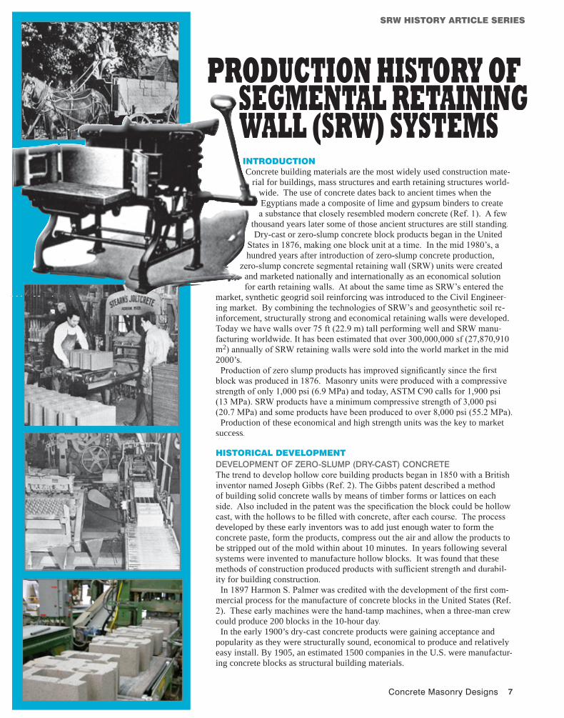
This is how concrete block was made in the very early days—and for a good many years thereafter in backyards and basements. Pictured here is the process involved in turning out one concrete block on a model of the early hand-tamp machines (Ref. 2).
The workman fills the machine with cement and ag-gregate, hand mixed on the ground.
He hand tamps the mix-ture.
He then discharg-es the finished block.
And then he car-ries it to a crude pallet for curing.
Figure 1: Modern Batch plant
early Block Production
Imag
e co
urte
sy o
f Col
umbi
a M
achi
nery
Concrete Masonry Designs 9
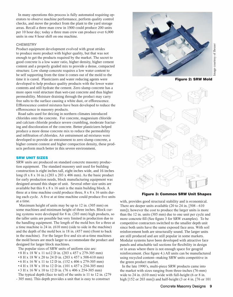
with, provides good structural stability and is economical. There are deeper units available (20 to 24 in. [508 - 610 mm]); however the cost to produce the larger units is more than the 12 in. units (305 mm) due to one unit per cycle and more concrete fill (See figure 3 for SRW examples). To be competitive contractors switched to the smaller depth unit since both units have the same exposed face area. With soil reinforcement both are structurally sound. The larger units are still produced and are still popular in some markets. Modular systems have been developed with attractive face panels and attachable tail sections for flexibility in design or in areas where there is not enough space for geogrid reinforcement. (See figure 4.) All units can be manufactured using recycled content--making SRW units competitive in the green product market.
In the late 1990’s, multi-piece SRW products came into the market with sizes ranging from three-inches (76-mm) wide to 24 in. (610 mm) wide with full-height (6 or 8 in. high [152 or 203 mm]) and half-height (3 or 4 in. [76 or 101
Concrete Masonry Designs 9
In many operations this process is fully automated requiring op-erators to observe machine performance, perform quality control checks, and move the product from the plant to the yard storage areas. Recall a three man crew in 1900 could produce 200 units per 10 hour day; today a three man crew can produce over 6,000 units in one 8 hour shift on one machine.
CheMistryProduct equipment development evolved with great strides to produce more product with higher quality, but that was not enough to get the products required by the market. The secret to good concrete is a low water ratio, higher density, higher cement content and a properly graded mix to provide a dense, compacted structure. Low slump concrete requires a low water content to be self supporting from the time it comes out of the mold to the time it is cured. Plasticizers and water reducing agents were developed to help produce quality products with the lower water contents and still hydrate the cement. Zero slump concrete has a more open void structure than wet-cast concrete and thus higher permeability. Moisture draining through the product may carry free salts to the surface causing a white dust, or efflorescence. Efflorescence control mixtures have been developed to reduce the efflorescence in masonry products.
Road salts used for deicing in northern climates introduced chlorides onto the concrete. For concrete, magnesium chloride and calcium chloride produce severe crumbling, moderate fractur-ing and discoloration of the concrete. Better plasticizers helped produce a more dense concrete mix to reduce the permeability and infiltration of chlorides. Air entrainment ad mixtures were developed to provide air entrainment to zero slump concrete, a higher cement content and higher compaction density, these prod-ucts perform much better in this severe environment.
SrW uNIt SIzeSSRW units are produced on standard concrete masonry produc-tion equipment. The standard masonry unit used for building construction is eight inches tall, eight inches wide, and 16 inches long (8 x 8 x 16 in.) (203 x 203 x 406 mm). As the basic product for early production needs, block manufacturing equipment was designed around this shape of unit. Several other size units are available but this 8 x 8 x 16 unit is the main building block. A three at a time machine could produce three, 8 x 8 x 16 units dur-ing each cycle. A five at at time machine could produce five units at a time.
Maximum height of units may be up to 12 in. (305 mm) on some machines and minimum height of three inches. Block cur-ing systems were developed for 8 in. (203 mm) high products, so the taller units are possible but very limited in production due to the handling equipment. The length of the mold box for a three at a time machine is 24 in. (610 mm) (side to side in the machine) and the depth of the mold box is 18 in. (457 mm) (front to back in the machine). For the larger five and six-at-a-time machines the mold boxes are much larger to accommodate the product and designed for larger block machines.
The popular sizes of SRW units of uniform size are:8 H x 18 W x 11 to12 D in. (203 x 457 x 279-305 mm)• 8 H x 18 W x 20 to 24 D in. (203 x 457 x 508-610 mm)• 6 H x 16 W x 11 to 12 D in. (152 x 406 x 279-305 mm)• 4 H x 18 W x 10 to 12 D in. (101 x 457 x 254-305 mm)• 3 H x 16 W x 10 to 12 D in. (76 x 406 x 254-305 mm)•
The typical depth (face to tail) of the units is 11 to 12 in. (279 - 305 mm). This depth provides a unit that is easy to construct
Figure 3: Common SrW unit Shapes
Figure 2: SrW Mold
Imag
e co
urte
sy o
f Bes
ser
10 Concrete Masonry Designs
mm]) units. The combination of these architectural units created a more natural look with random shaped face units. There are systems in the market with two, four, five, or six different sized units in the same wall panel (see figure 5).
Single depth facings units were developed mostly for grav-ity and mechanically stabilized earth (MSE) wall construc-tion and the multi-piece systems were developed for the architectural landscaping applications.
ArCHIteCturAl DeSIgNMarkets for the SRW products began as residential and small commercial projects where the SRW’s were alterna-tives to timber walls, boulder walls or poured concrete walls. Face textures were either straight faced units (mold finished) or a fluted or textured face created in the mold. The standard colors were concrete gray or tan.
Figure 4: Modular unit with recycled Content
Market demand grew quickly for SRW products and producers developed more facing options for the consumer.
harD-splitIn the mid 80’s manufacturers incorporated the splitting system to break a thin slice off the face of a cured SRW unit to produce a more rustic appearance.
The split aggregates and sometimes multicolored aggregates gave the product an attractive appearance (See figure 6).
abraDeDtM or soft-splittM
Mold designers and producers developed different systems in the mold that would roughen the wet-concrete face as the unit was extracted from the mold. These systems yielded an attractive appearance and reduced production costs by eliminating the han-dling, splitting and re-grinding of the disposed block surface.
staMpeD faCePlain facing textures, split facing, and abraded faces were avail-able in the market and the next step was a stamped face unit pro-duced in the mold, extruded and cured. These units are popular in the lawn and garden retail markets and some commercial product lines (see figures 4 and 7).
tuMbleD faCeManufacturing a ‘rock-like’ texture in a mold box leaves sharp, 90 degree edge on the top and bottom of the units. Tumbling is a process where the units are placed in a round drum and rolled or tumbled. As the units collide with other units or impact the edge of the drum, the outside sharp edges are chipped off, rounding off the machine made surfaces. Several abraded and smaller hard split units are tumbled to create a more natural stone appearance (see figure 8).
ConCrete ColorsWhen SRW’s first entered the market they were the standard concrete grey, tan or brown color that were typical for concrete masonry products. As demand continued to develop manufactures developed capacity to produce colored units and many added systems to produce variegated colors combining two or three dif-ferent colors to give the units a more natural colored appearance (see figure 9).
SpeCIFICAtIoNS For SrW’SThe ASTM is the standards organization in the U.S. During the beginning of SRW production the standard dry cast block specifi-cations were applied to the SRW units, ASTM C90. These were:
ASTM C90, Standard Specification for Loadbearing Con-• crete Masonry UnitsCompressive strength – 1900 psi (13.1 MPa) (minimum net • average)Absorption – 18-13 pcf (288-208 kg/m• 3)Tolerance +/- 1/8 in. (3 mm) from the manufacturers pub-• lished values.
As the industry developed SRW products required higher com-pressive strengths to meet the requirements set by the engineering community for wet-cast concrete products. As this was evolving, industry decided a new ASTM standard was needed that addressed the manufacturing and production needs of SRW products as their use, application and requirements were different from the load bearing products used for building masonry structures. This new standard was:
Figure 5: Multi-Sized units
Imag
e co
urte
sy o
f Alla
n B
lock
Imag
e co
urte
sy o
f Alla
n B
lock
Figure 6: Hard-Split SrW Facing
Imag
e co
urte
sy o
f Ver
sa-lo
k
Concrete Masonry Designs 11
ASTM C1372, Standard Specification for Segmental Retaining Wall Units
Compressive strength – 3,000 psi (20.7 MPa) (minimun net • average)Absorption - 18-13 pcf (288-208 kg/m• 3) depending on the densityTolerance - +/- 1/8 in. (3 mm) from the manufacturers • published values
In the late 1980’s, SRW products were introduced into the high-way transportation market. The American Association of State Highway Transportation Officials (AASTHO) Bridge Manual (Ref. 3) requirements for concrete products were:
Normal Weight and Structural Lightweight Concrete • (AASHTO 5.4.2) Compressive strength - 4,000 psi (27.6 MPa)• Tolerance - +/- 1/16 in. (1.6 mm) from the manufacturer’s • published values
QuAlIty CoNtrol / QuAlIty ASSurANCeProduct capacities were increased significantly to meet the market demands, chemicals and admixes were developed to enhance manufacturing and product performance and specifications were developed for using SRW products in more critical applications. Introduction of the products into the highway markets required higher quality control standards and product checks to ensure quality products were used in manufacturing met the department of transportation specifications.
Most manufacturers of SRW products have a quality control pro-gram in place and published QA/QC procedures. Units are tested on a routine bases for strength, absorption, density and in northern climates, or durability.
SuMMAryProduction and quality of masonry concrete came a long way since the first zero slump units were produced in 1850 up the 1980’s. In the last 25 years there have been remarkable improve-ments in production with solid state electronics, increased market demand from the landscaping markets and surprising improve-ments in the architectural finishes available. Concrete mix designs and manufacturing techniques have been improved to provide more durable units for severe environments and chemical addi-tives were developed to help achieve better compaction, greater density and even air entrainment.
Customer desires prompted manufacturers to produce units with a variety of color options, solid color or variegated color mixes. Equipment manufacturers and designers were able to make multi-piece SRW units to create very pleasing architectural designs for retaining walls.
A combination of a colorful SRW retaining wall, permeable paver walkways and drives with surrounding gardens with concrete edger’s is a perfect Low Impact Design (LID) solution using environmentally friendly components to create an afford-able, sustainable solution to any project that not only improves the value of the property and solves structural issues, but helps save the environment.
As Dr. Richard Bathurst, a leader in Geotechnical Engineering, stated at an international meeting in Sydney, Australia in 1999, “SRW’s and geosynthetic reinforcements have revolutionized Civil Engineering for earth retaining structures”. We believe his statement was correct and it just continues to get better. CMD
Figure 9: Color options
reFereNCeS1 www.britannica.com2 Bell, Joseph, From the Carriage Age….. to the Space