222
SRX650 Services Gateway Hardware Guide Modified: 2016-08-22 Copyright © 2016, Juniper Networks, Inc.

SRX650 Services Gateway Hardware Guide
Modified: 2016-08-22
Copyright © 2016, Juniper Networks, Inc.

Juniper Networks, Inc.1133 Innovation WaySunnyvale, California 94089USA408-745-2000www.juniper.net
Copyright © 2016, Juniper Networks, Inc. All rights reserved.
Juniper Networks, Junos, Steel-Belted Radius, NetScreen, and ScreenOS are registered trademarks of Juniper Networks, Inc. in the UnitedStates and other countries. The Juniper Networks Logo, the Junos logo, and JunosE are trademarks of Juniper Networks, Inc. All othertrademarks, service marks, registered trademarks, or registered service marks are the property of their respective owners.
Juniper Networks assumes no responsibility for any inaccuracies in this document. Juniper Networks reserves the right to change, modify,transfer, or otherwise revise this publication without notice.
SRX650 Services Gateway Hardware GuideCopyright © 2016, Juniper Networks, Inc.All rights reserved.
The information in this document is current as of the date on the title page.
YEAR 2000 NOTICE
Juniper Networks hardware and software products are Year 2000 compliant. Junos OS has no known time-related limitations through theyear 2038. However, the NTP application is known to have some difficulty in the year 2036.
ENDUSER LICENSE AGREEMENT
The Juniper Networks product that is the subject of this technical documentation consists of (or is intended for use with) Juniper Networkssoftware. Use of such software is subject to the terms and conditions of the End User License Agreement (“EULA”) posted athttp://www.juniper.net/support/eula.html. By downloading, installing or using such software, you agree to the terms and conditions ofthat EULA.
Copyright © 2016, Juniper Networks, Inc.ii

Table of Contents
About the Documentation . . . . . . . . . . . . . . . . . . . . . . . . . . . . . . . . . . . . . . . . . . . . xiii
Documentation and Release Notes . . . . . . . . . . . . . . . . . . . . . . . . . . . . . . . . . xiii
Supported Platforms . . . . . . . . . . . . . . . . . . . . . . . . . . . . . . . . . . . . . . . . . . . . xiii
Documentation Conventions . . . . . . . . . . . . . . . . . . . . . . . . . . . . . . . . . . . . . . xiii
Documentation Feedback . . . . . . . . . . . . . . . . . . . . . . . . . . . . . . . . . . . . . . . . . xv
Requesting Technical Support . . . . . . . . . . . . . . . . . . . . . . . . . . . . . . . . . . . . . xvi
Self-Help Online Tools and Resources . . . . . . . . . . . . . . . . . . . . . . . . . . . xvi
Opening a Case with JTAC . . . . . . . . . . . . . . . . . . . . . . . . . . . . . . . . . . . . . xvi
Part 1 Overview
Chapter 1 Introduction . . . . . . . . . . . . . . . . . . . . . . . . . . . . . . . . . . . . . . . . . . . . . . . . . . . . . . . 3
SRX650 Services Gateway Description . . . . . . . . . . . . . . . . . . . . . . . . . . . . . . . . . . 3
SRX650 Services Gateway Features and Functions . . . . . . . . . . . . . . . . . . . . . . . . . 3
SRX650 Services Gateway Software Features and Licenses . . . . . . . . . . . . . . . . . 4
SRX650 Services Gateway Power over Ethernet Overview . . . . . . . . . . . . . . . . . . . 8
Accessing the SRX650 Services Gateway . . . . . . . . . . . . . . . . . . . . . . . . . . . . . . . . 10
Chapter 2 Hardware Component Overview . . . . . . . . . . . . . . . . . . . . . . . . . . . . . . . . . . . . . 11
SRX650 Services Gateway Services and Routing Engine 6 . . . . . . . . . . . . . . . . . . . 11
SRX650 Services Gateway Boot Devices and Dual-Root Partitioning
Scheme . . . . . . . . . . . . . . . . . . . . . . . . . . . . . . . . . . . . . . . . . . . . . . . . . . . . . . . 14
Chapter 3 Chassis Description . . . . . . . . . . . . . . . . . . . . . . . . . . . . . . . . . . . . . . . . . . . . . . . . 17
SRX650 Services Gateway Chassis . . . . . . . . . . . . . . . . . . . . . . . . . . . . . . . . . . . . . 17
SRX650 Services Gateway Front Panel . . . . . . . . . . . . . . . . . . . . . . . . . . . . . . . . . . 18
SRX650 Services Gateway Back Panel . . . . . . . . . . . . . . . . . . . . . . . . . . . . . . . . . . 24
Chapter 4 Interface Module Description . . . . . . . . . . . . . . . . . . . . . . . . . . . . . . . . . . . . . . . 27
SRX650 Services Gateway Gigabit-Backplane Physical Interface Modules . . . . . 27
Chapter 5 Cooling System Description . . . . . . . . . . . . . . . . . . . . . . . . . . . . . . . . . . . . . . . . . 31
SRX650 Services Gateway Cooling System . . . . . . . . . . . . . . . . . . . . . . . . . . . . . . 31
Chapter 6 Power System Description . . . . . . . . . . . . . . . . . . . . . . . . . . . . . . . . . . . . . . . . . 33
SRX650 Services Gateway Power Supply . . . . . . . . . . . . . . . . . . . . . . . . . . . . . . . 33
Part 2 Site Planning and Specifications
Chapter 7 Planning and Preparing the Site . . . . . . . . . . . . . . . . . . . . . . . . . . . . . . . . . . . . 39
Site Preparation Checklist for the SRX650 Services Gateway . . . . . . . . . . . . . . . 39
General Site Installation Guidelines for the SRX650 Services Gateway . . . . . . . . 41
SRX650 Services Gateway Environmental Specifications . . . . . . . . . . . . . . . . . . . 42
iiiCopyright © 2016, Juniper Networks, Inc.
Chapter 8 Rack Requirements . . . . . . . . . . . . . . . . . . . . . . . . . . . . . . . . . . . . . . . . . . . . . . . 45
Rack-Mounting Requirements and Warnings . . . . . . . . . . . . . . . . . . . . . . . . . . . . . 45
SRX650 Services Gateway Rack Size and Strength Requirements . . . . . . . . . . . 49
SRX650 Services Gateway Spacing of Mounting Bracket and Flange Holes . . . . 49
Clearance Requirements for Airflow and Hardware Maintenance of the SRX650
Services Gateway . . . . . . . . . . . . . . . . . . . . . . . . . . . . . . . . . . . . . . . . . . . . . . . 50
Chapter 9 Cabinet Requirements . . . . . . . . . . . . . . . . . . . . . . . . . . . . . . . . . . . . . . . . . . . . . 53
SRX650 Services Gateway Cabinet Size and Clearance Requirements . . . . . . . . 53
SRX650 Services Gateway Cabinet Airflow Requirements . . . . . . . . . . . . . . . . . . 54
Chapter 10 Power Requirements and Specifications . . . . . . . . . . . . . . . . . . . . . . . . . . . . . 55
SRX650 Services Gateway Electrical Wiring Guidelines . . . . . . . . . . . . . . . . . . . . 55
SRX650 Services Gateway Supported AC Power Cords . . . . . . . . . . . . . . . . . . . . 56
SRX650 Services Gateway DC Power Supply Electrical Specifications . . . . . . . . 58
SRX650 Services Gateway AC Power Supply Electrical Specifications . . . . . . . . 58
SRX650 Services Gateway DC Power Cable Specifications . . . . . . . . . . . . . . . . . 59
SRX650 Services Gateway Power Requirements . . . . . . . . . . . . . . . . . . . . . . . . . 60
Chapter 11 Cable Specifications and Pinouts . . . . . . . . . . . . . . . . . . . . . . . . . . . . . . . . . . . . 61
Interface Cabling and Wiring Specifications for the SRX650 Services
Gateway . . . . . . . . . . . . . . . . . . . . . . . . . . . . . . . . . . . . . . . . . . . . . . . . . . . . . . . 61
RJ-45 Connector Pinouts for the SRX650 Services Gateway Ethernet Port . . . . . 61
RJ-45 Connector Pinouts for the SRX650 Services Gateway Console Port . . . . . 62
Part 3 Initial Installation and Configuration
Chapter 12 Installation Overview . . . . . . . . . . . . . . . . . . . . . . . . . . . . . . . . . . . . . . . . . . . . . . 65
Installation Overview for the SRX650 Services Gateway . . . . . . . . . . . . . . . . . . . 65
Required Tools and Parts for Installing the SRX650 Services Gateway . . . . . . . . 65
SRX650 Services Gateway Autoinstallation Overview . . . . . . . . . . . . . . . . . . . . . 66
Chapter 13 Unpacking the Services Gateway . . . . . . . . . . . . . . . . . . . . . . . . . . . . . . . . . . . . 67
Required Tools and Parts for Unpacking the SRX650 Services Gateway . . . . . . . 67
Unpacking the SRX650 Services Gateway . . . . . . . . . . . . . . . . . . . . . . . . . . . . . . . 67
Verifying Parts Received with the SRX650 Services Gateway . . . . . . . . . . . . . . . . 68
Chapter 14 Installing the Mounting Hardware . . . . . . . . . . . . . . . . . . . . . . . . . . . . . . . . . . . 71
Preparing the SRX650 Services Gateway for Rack-Mount Installation . . . . . . . . . 71
Connecting the SRX650 Services Gateway to the Building Structure . . . . . . . . . . 71
Chapter 15 Installing the Services Gateway . . . . . . . . . . . . . . . . . . . . . . . . . . . . . . . . . . . . . 73
Installation Instructions Warning . . . . . . . . . . . . . . . . . . . . . . . . . . . . . . . . . . . . . . . 73
Installing the SRX650 Services Gateway in a Rack . . . . . . . . . . . . . . . . . . . . . . . . 74
Installing the Fan Tray on the SRX650 Services Gateway . . . . . . . . . . . . . . . . . . . 75
Installing the Air Filter on the SRX650 Services Gateway . . . . . . . . . . . . . . . . . . . 75
Installing the SRE on the SRX650 Services Gateway . . . . . . . . . . . . . . . . . . . . . . . 77
Installing an AC Power Supply on the SRX650 Services Gateway . . . . . . . . . . . . 78
Installing a DC Power Supply on the SRX650 Services Gateway . . . . . . . . . . . . . 79
Copyright © 2016, Juniper Networks, Inc.iv
SRX650 Services Gateway Hardware Guide

Chapter 16 Grounding the SRX650 Services Gateway . . . . . . . . . . . . . . . . . . . . . . . . . . . . 81
Required Tools and Parts for Grounding, Powering On, and Powering Off the
SRX650 Services Gateway . . . . . . . . . . . . . . . . . . . . . . . . . . . . . . . . . . . . . . . . 81
SRX650 Services Gateway Grounding Specifications . . . . . . . . . . . . . . . . . . . . . . 81
Grounding the SRX650 Services Gateway . . . . . . . . . . . . . . . . . . . . . . . . . . . . . . . 82
Chapter 17 Connecting the SRX650 Services Gateway to External Devices . . . . . . . . . 85
Required Tools and Parts for Connecting the SRX650 Services Gateway . . . . . . 85
Organizing Interface Cables on the SRX650 Services Gateway . . . . . . . . . . . . . . 85
Connecting the Modem to the Console Port on the SRX650 Services
Gateway . . . . . . . . . . . . . . . . . . . . . . . . . . . . . . . . . . . . . . . . . . . . . . . . . . . . . . 86
Connecting the CLI at the User End for the SRX650 Services Gateway . . . . . . . . 86
Connecting the Modem at the SRX650 Services Gateway End . . . . . . . . . . . . . . . 87
Chapter 18 Providing Power to the SRX650 Services Gateway . . . . . . . . . . . . . . . . . . . . 89
Connecting the SRX650 Services Gateway to the AC Power Supply . . . . . . . . . . 89
Connecting an AC Power Cord to the SRX650 Services Gateway . . . . . . . . . . . . 90
Connecting the SRX650 Services Gateway to the DC Power Supply . . . . . . . . . . . 91
Powering On the SRX650 Services Gateway . . . . . . . . . . . . . . . . . . . . . . . . . . . . . 92
Powering Off the SRX650 Services Gateway . . . . . . . . . . . . . . . . . . . . . . . . . . . . . 93
Chapter 19 Performing Initial Configuration . . . . . . . . . . . . . . . . . . . . . . . . . . . . . . . . . . . . . 95
SRX650 Services Gateway Software Configuration Overview . . . . . . . . . . . . . . . 95
SRX650 Services Gateway Basic Settings . . . . . . . . . . . . . . . . . . . . . . . . . . . . . . . 96
Connecting to the SRX650 Services Gateway Setup Wizard . . . . . . . . . . . . . . . . 98
SRX650 Services Gateway Secure Web Access Overview . . . . . . . . . . . . . . . . . . 100
SRX650 Services Gateway Secure CLI Access Overview . . . . . . . . . . . . . . . . . . . 101
Connecting to the SRX650 Services Gateway from the CLI Locally . . . . . . . . . . 102
Connecting to the SRX650 Services Gateway from the CLI Remotely . . . . . . . . 104
Viewing Factory-Default Settings of the SRX650 Services Gateway . . . . . . . . . 105
Configuring Basic Settings for the SRX650 Services Gateway with the CLI or the
J-Web Interface . . . . . . . . . . . . . . . . . . . . . . . . . . . . . . . . . . . . . . . . . . . . . . . . . 111
Displaying Basic Connectivity Configurations for the SRX650 Services
Gateway . . . . . . . . . . . . . . . . . . . . . . . . . . . . . . . . . . . . . . . . . . . . . . . . . . . . . . 115
Built-In Ethernet Ports for the SRX650 Services Gateway . . . . . . . . . . . . . . . . . . 116
Part 4 Maintaining and Troubleshooting Components
Chapter 20 Maintaining Components . . . . . . . . . . . . . . . . . . . . . . . . . . . . . . . . . . . . . . . . . . 121
Required Tools and Parts for Maintaining the SRX650 Services Gateway
Hardware Components . . . . . . . . . . . . . . . . . . . . . . . . . . . . . . . . . . . . . . . . . . 121
Routine Maintenance Procedures for the SRX650 Services Gateway . . . . . . . . . 121
Maintaining the SRX650 Services Gateway Cooling System Components . . . . . 122
Maintaining the SRX650 Services Gateway Power Supply . . . . . . . . . . . . . . . . . . 122
vCopyright © 2016, Juniper Networks, Inc.
Table of Contents
Chapter 21 Troubleshooting Components . . . . . . . . . . . . . . . . . . . . . . . . . . . . . . . . . . . . . 123
Troubleshooting with the CLI on the SRX650 Services Gateway . . . . . . . . . . . . . 123
Troubleshooting with LEDs on the SRX650 Services Gateway . . . . . . . . . . . . . . 123
Troubleshooting with Chassis and Interface Alarm Messages on the SRX650
Services Gateway . . . . . . . . . . . . . . . . . . . . . . . . . . . . . . . . . . . . . . . . . . . . . . . 127
Troubleshooting the Power System on the SRX650 Services Gateway . . . . . . . . 129
Using the RESET CONFIG Button on the SRX650 Services Gateway . . . . . . . . . 132
Changing the RESET CONFIG Button Behavior on the SRX650 Services
Gateway . . . . . . . . . . . . . . . . . . . . . . . . . . . . . . . . . . . . . . . . . . . . . . . . . . . . . . 133
Resetting the SRX650 Services Gateway . . . . . . . . . . . . . . . . . . . . . . . . . . . . . . . 133
Part 5 Replacing Components
Chapter 22 Overview of Replacing Components . . . . . . . . . . . . . . . . . . . . . . . . . . . . . . . . 137
Required Tools and Parts for Replacing Hardware Components on the SRX650
Services Gateway . . . . . . . . . . . . . . . . . . . . . . . . . . . . . . . . . . . . . . . . . . . . . . . 137
Chapter 23 Replacing the Services and Routing Engine (SRE) Module . . . . . . . . . . . . . 139
Removing the SRE from the SRX650 Services Gateway . . . . . . . . . . . . . . . . . . . 139
Chapter 24 Replacing Power System Components . . . . . . . . . . . . . . . . . . . . . . . . . . . . . . 141
Removing an AC Power Supply from the SRX650 Services Gateway . . . . . . . . . . 141
Disconnecting an AC Power Cord from the SRX650 Services Gateway . . . . . . . . 142
Removing a DC Power Supply on the SRX650 Services Gateway . . . . . . . . . . . . 143
Removing a DC Power Supply Cable from the SRX650 Services Gateway . . . . . 144
Chapter 25 Replacing Cooling System Components . . . . . . . . . . . . . . . . . . . . . . . . . . . . . 147
Removing the Fan Tray on the SRX650 Services Gateway . . . . . . . . . . . . . . . . . . 147
Removing the Air Filter on the SRX650 Services Gateway . . . . . . . . . . . . . . . . . . 148
Chapter 26 Contacting Customer Support and Returning Components . . . . . . . . . . . . 151
Contacting Customer Support . . . . . . . . . . . . . . . . . . . . . . . . . . . . . . . . . . . . . . . . 151
Return Procedure for the SRX650 Services Gateway . . . . . . . . . . . . . . . . . . . . . . 152
Locating the SRX650 Services Gateway Chassis Serial Number and Agency
Labels . . . . . . . . . . . . . . . . . . . . . . . . . . . . . . . . . . . . . . . . . . . . . . . . . . . . . . . . 152
Locating the SRX650 Services Gateway GPIM Serial Number Label . . . . . . . . . . 153
Listing the SRX650 Services Gateway Component Details with the CLI . . . . . . . 153
Information You Might Need to Supply to JTAC . . . . . . . . . . . . . . . . . . . . . . . . . . . 154
Required Tools and Parts for Packing the SRX650 Services Gateway . . . . . . . . . 154
Packing the SRX650 Services Gateway for Shipment . . . . . . . . . . . . . . . . . . . . . 155
Packing the SRX650 Services Gateway Components for Shipment . . . . . . . . . . 156
Part 6 Safety
Chapter 27 General Safety Guidelines and Warnings . . . . . . . . . . . . . . . . . . . . . . . . . . . . 159
SRX650 Services Gateway Definition of Safety Warning Levels . . . . . . . . . . . . . 159
SRX650 Services Gateway General Safety Guidelines and Warnings . . . . . . . . . 161
SRX650 Services Gateway Safety Requirements, Warnings, and Guidelines . . . 162
Restricted Access Area Warning . . . . . . . . . . . . . . . . . . . . . . . . . . . . . . . . . . . . . . 162
Qualified Personnel Warning . . . . . . . . . . . . . . . . . . . . . . . . . . . . . . . . . . . . . . . . . 163
Copyright © 2016, Juniper Networks, Inc.vi
SRX650 Services Gateway Hardware Guide

Preventing Electrostatic Discharge Damage to the SRX650 Services
Gateway . . . . . . . . . . . . . . . . . . . . . . . . . . . . . . . . . . . . . . . . . . . . . . . . . . . . . . 164
Chapter 28 Fire Safety Requirements . . . . . . . . . . . . . . . . . . . . . . . . . . . . . . . . . . . . . . . . . . 167
SRX650 Services Gateway Fire Safety Requirements and Fire Suppression
Equipment . . . . . . . . . . . . . . . . . . . . . . . . . . . . . . . . . . . . . . . . . . . . . . . . . . . . 167
Chapter 29 Laser and LED Safety Guidelines and Warnings . . . . . . . . . . . . . . . . . . . . . . 169
General Laser Safety Guidelines . . . . . . . . . . . . . . . . . . . . . . . . . . . . . . . . . . . . . . 169
Class 1 Laser Warning . . . . . . . . . . . . . . . . . . . . . . . . . . . . . . . . . . . . . . . . . . . . . . . 170
Class 1 LED Product Warning . . . . . . . . . . . . . . . . . . . . . . . . . . . . . . . . . . . . . . . . . 170
Laser Beam Warning . . . . . . . . . . . . . . . . . . . . . . . . . . . . . . . . . . . . . . . . . . . . . . . . 171
Radiation from Open Port Apertures Warning . . . . . . . . . . . . . . . . . . . . . . . . . . . . 172
Chapter 30 Maintenance and Operational Safety Guidelines and Warnings . . . . . . . . 175
Battery-Handling Warning . . . . . . . . . . . . . . . . . . . . . . . . . . . . . . . . . . . . . . . . . . . 175
Lightning Activity Warning . . . . . . . . . . . . . . . . . . . . . . . . . . . . . . . . . . . . . . . . . . . 176
Jewelry Removal Warning . . . . . . . . . . . . . . . . . . . . . . . . . . . . . . . . . . . . . . . . . . . . 177
Operating Temperature Warning . . . . . . . . . . . . . . . . . . . . . . . . . . . . . . . . . . . . . . 179
Product Disposal Warning . . . . . . . . . . . . . . . . . . . . . . . . . . . . . . . . . . . . . . . . . . . 180
Lithium Battery . . . . . . . . . . . . . . . . . . . . . . . . . . . . . . . . . . . . . . . . . . . . . . . . . . . . 181
Chapter 31 Electrical Safety Guidelines andWarnings . . . . . . . . . . . . . . . . . . . . . . . . . . . 183
In Case of Electrical Accident . . . . . . . . . . . . . . . . . . . . . . . . . . . . . . . . . . . . . . . . . 183
General Electrical Safety Guidelines and Warnings . . . . . . . . . . . . . . . . . . . . . . . 183
AC Power Electrical Safety Guidelines . . . . . . . . . . . . . . . . . . . . . . . . . . . . . . . . . . 184
DC Power Electrical Safety Guidelines . . . . . . . . . . . . . . . . . . . . . . . . . . . . . . . . . 185
Chapter 32 Agency Approvals and Regulatory Compliance Information . . . . . . . . . . . 193
SRX650 Services Gateway Agency Approvals . . . . . . . . . . . . . . . . . . . . . . . . . . . 193
SRX650 Services Gateway Acoustic Noise Compliance Statements . . . . . . . . . 194
Canada . . . . . . . . . . . . . . . . . . . . . . . . . . . . . . . . . . . . . . . . . . . . . . . . . . . . . . . . . . 194
European Community . . . . . . . . . . . . . . . . . . . . . . . . . . . . . . . . . . . . . . . . . . . . . . . 195
Japan . . . . . . . . . . . . . . . . . . . . . . . . . . . . . . . . . . . . . . . . . . . . . . . . . . . . . . . . . . . . 195
United States . . . . . . . . . . . . . . . . . . . . . . . . . . . . . . . . . . . . . . . . . . . . . . . . . . . . . 195
Part 7 Index
Index . . . . . . . . . . . . . . . . . . . . . . . . . . . . . . . . . . . . . . . . . . . . . . . . . . . . . . . . 199
viiCopyright © 2016, Juniper Networks, Inc.
Table of Contents

Copyright © 2016, Juniper Networks, Inc.viii
SRX650 Services Gateway Hardware Guide

List of Figures
Part 1 Overview
Chapter 2 Hardware Component Overview . . . . . . . . . . . . . . . . . . . . . . . . . . . . . . . . . . . . . 11
Figure 1: Services and Routing Engine . . . . . . . . . . . . . . . . . . . . . . . . . . . . . . . . . . . . 12
Chapter 3 Chassis Description . . . . . . . . . . . . . . . . . . . . . . . . . . . . . . . . . . . . . . . . . . . . . . . . 17
Figure 2: SRX650 Services Gateway Front Panel . . . . . . . . . . . . . . . . . . . . . . . . . . 18
Figure 3: SRX650 Services Gateway Slot Numbers . . . . . . . . . . . . . . . . . . . . . . . . 18
Figure 4: SRX650 Services Gateway Back Panel . . . . . . . . . . . . . . . . . . . . . . . . . . 24
Chapter 4 Interface Module Description . . . . . . . . . . . . . . . . . . . . . . . . . . . . . . . . . . . . . . . 27
Figure 5: SRX650 Services Gateway Slot Numbers . . . . . . . . . . . . . . . . . . . . . . . . 28
Figure 6: Example of a Standard GPIM (Installs in One Standard Slot) . . . . . . . . 28
Figure 7: Example of a Double-High, Single-Wide XPIM . . . . . . . . . . . . . . . . . . . . . 28
Figure 8: Example of a Double-High, Double-Wide XPIM . . . . . . . . . . . . . . . . . . . 28
Chapter 6 Power System Description . . . . . . . . . . . . . . . . . . . . . . . . . . . . . . . . . . . . . . . . . 33
Figure 9: Single AC Power Supply for the SRX650 Services Gateway . . . . . . . . . . 33
Figure 10: Single DC Power Supply for the SRX650 Services Gateway . . . . . . . . . 34
Part 2 Site Planning and Specifications
Chapter 8 Rack Requirements . . . . . . . . . . . . . . . . . . . . . . . . . . . . . . . . . . . . . . . . . . . . . . . 45
Figure 11: Airflow Through the Chassis . . . . . . . . . . . . . . . . . . . . . . . . . . . . . . . . . . . 51
Chapter 10 Power Requirements and Specifications . . . . . . . . . . . . . . . . . . . . . . . . . . . . . 55
Figure 12: AC Plug Types . . . . . . . . . . . . . . . . . . . . . . . . . . . . . . . . . . . . . . . . . . . . . . 57
Part 3 Initial Installation and Configuration
Chapter 15 Installing the Services Gateway . . . . . . . . . . . . . . . . . . . . . . . . . . . . . . . . . . . . . 73
Figure 13: Installing the Fan Tray . . . . . . . . . . . . . . . . . . . . . . . . . . . . . . . . . . . . . . . 75
Figure 14: Installing the Air Filter . . . . . . . . . . . . . . . . . . . . . . . . . . . . . . . . . . . . . . . 76
Figure 15: Tightening Captive Screws . . . . . . . . . . . . . . . . . . . . . . . . . . . . . . . . . . . 76
Figure 16: Installing the Services and Routing Engine (SRE) . . . . . . . . . . . . . . . . . . 77
Figure 17: Installing an AC Power Supply on the SRX650 Services Gateway . . . . . 78
Figure 18: Installing a DC Power Supply on an SRX650 Services Gateway . . . . . . 79
Chapter 17 Connecting the SRX650 Services Gateway to External Devices . . . . . . . . . 85
Figure 19: Console Cable Connector . . . . . . . . . . . . . . . . . . . . . . . . . . . . . . . . . . . . 86
Chapter 19 Performing Initial Configuration . . . . . . . . . . . . . . . . . . . . . . . . . . . . . . . . . . . . . 95
Figure 20: Connecting to the Ethernet Port on the SRX650 Services Gateway . . 99
Figure 21: Ethernet Cable Connector (RJ-45) . . . . . . . . . . . . . . . . . . . . . . . . . . . . . 99
ixCopyright © 2016, Juniper Networks, Inc.

Figure 22: Connecting to the Console Port on the SRX650 Services Gateway . . 103
Part 5 Replacing Components
Chapter 23 Replacing the Services and Routing Engine (SRE) Module . . . . . . . . . . . . . 139
Figure 23: Removing the Services and Routing Engine (SRE) . . . . . . . . . . . . . . . 140
Chapter 24 Replacing Power System Components . . . . . . . . . . . . . . . . . . . . . . . . . . . . . . 141
Figure 24: Removing an AC Power Supply from the SRX650 Services
Gateway . . . . . . . . . . . . . . . . . . . . . . . . . . . . . . . . . . . . . . . . . . . . . . . . . . . . . . 142
Figure 25: Removing a DC Power Supply from the SRX650 Services Gateway . . 144
Chapter 25 Replacing Cooling System Components . . . . . . . . . . . . . . . . . . . . . . . . . . . . . 147
Figure 26: Removing the Fan Tray from the Services Gateway . . . . . . . . . . . . . . . 148
Figure 27: Loosening Captive Screws . . . . . . . . . . . . . . . . . . . . . . . . . . . . . . . . . . . 149
Figure 28: Removing the Air Filter . . . . . . . . . . . . . . . . . . . . . . . . . . . . . . . . . . . . . 150
Part 6 Safety
Chapter 27 General Safety Guidelines and Warnings . . . . . . . . . . . . . . . . . . . . . . . . . . . . 159
Figure 29: Placing a Component into an Electrostatic Bag . . . . . . . . . . . . . . . . . . 165
Copyright © 2016, Juniper Networks, Inc.x
SRX650 Services Gateway Hardware Guide
List of Tables
About the Documentation . . . . . . . . . . . . . . . . . . . . . . . . . . . . . . . . . . . . . . . . . xiii
Table 1: Notice Icons . . . . . . . . . . . . . . . . . . . . . . . . . . . . . . . . . . . . . . . . . . . . . . . . . xiv
Table 2: Text and Syntax Conventions . . . . . . . . . . . . . . . . . . . . . . . . . . . . . . . . . . xiv
Part 1 Overview
Chapter 1 Introduction . . . . . . . . . . . . . . . . . . . . . . . . . . . . . . . . . . . . . . . . . . . . . . . . . . . . . . . 3
Table 3: Software Features and Licenses . . . . . . . . . . . . . . . . . . . . . . . . . . . . . . . . . 5
Table 4: SRX650 Services Gateway PoE Specifications . . . . . . . . . . . . . . . . . . . . . 9
Chapter 2 Hardware Component Overview . . . . . . . . . . . . . . . . . . . . . . . . . . . . . . . . . . . . . 11
Table 5: Services and Routing Engine Component Descriptions . . . . . . . . . . . . . . . 12
Chapter 3 Chassis Description . . . . . . . . . . . . . . . . . . . . . . . . . . . . . . . . . . . . . . . . . . . . . . . . 17
Table 6: Physical Specifications for the SRX650 Services Gateway . . . . . . . . . . . . 17
Table 7: SRX650 Services Gateway Front Panel Components . . . . . . . . . . . . . . . . 19
Table 8: SRX650 Services Gateway Back Panel Components . . . . . . . . . . . . . . . 25
Chapter 6 Power System Description . . . . . . . . . . . . . . . . . . . . . . . . . . . . . . . . . . . . . . . . . 33
Table 9: Component Power Output/Consumption . . . . . . . . . . . . . . . . . . . . . . . . 34
Part 2 Site Planning and Specifications
Chapter 7 Planning and Preparing the Site . . . . . . . . . . . . . . . . . . . . . . . . . . . . . . . . . . . . 39
Table 10: Site Preparation Checklist for SRX650 Services Gateway
Installation . . . . . . . . . . . . . . . . . . . . . . . . . . . . . . . . . . . . . . . . . . . . . . . . . . . . 39
Table 11: SRX650 Services Gateway Environmental Specifications . . . . . . . . . . . 42
Chapter 8 Rack Requirements . . . . . . . . . . . . . . . . . . . . . . . . . . . . . . . . . . . . . . . . . . . . . . . 45
Table 12: Clearance Requirements for the SRX650 Services Gateway . . . . . . . . . 50
Chapter 10 Power Requirements and Specifications . . . . . . . . . . . . . . . . . . . . . . . . . . . . . 55
Table 13: Site Electrical Wiring Guidelines for the SRX650 Services Gateway . . . 55
Table 14: AC Power Cord Specifications . . . . . . . . . . . . . . . . . . . . . . . . . . . . . . . . . 57
Table 15: DC Power Supply Electrical Specifications for the SRX650 Services
Gateway . . . . . . . . . . . . . . . . . . . . . . . . . . . . . . . . . . . . . . . . . . . . . . . . . . . . . . 58
Table 16: AC Power Supply Electrical Specifications for the SRX650 Services
Gateway . . . . . . . . . . . . . . . . . . . . . . . . . . . . . . . . . . . . . . . . . . . . . . . . . . . . . . 58
Table 17: DC Power Cable Specifications . . . . . . . . . . . . . . . . . . . . . . . . . . . . . . . . 59
Chapter 11 Cable Specifications and Pinouts . . . . . . . . . . . . . . . . . . . . . . . . . . . . . . . . . . . . 61
Table 18: Cable and Wire Specifications for Ports and Alarm Interfaces . . . . . . . . 61
Table 19: RJ-45 Connector Pinouts for Services Gateway Ethernet Port . . . . . . . . 62
xiCopyright © 2016, Juniper Networks, Inc.
Table 20: RJ-45 Connector Pinouts for the Services Gateway Console Port . . . . . 62
Part 3 Initial Installation and Configuration
Chapter 13 Unpacking the Services Gateway . . . . . . . . . . . . . . . . . . . . . . . . . . . . . . . . . . . . 67
Table 21: Parts List for a Fully Configured SRX650 Services Gateway . . . . . . . . . 68
Table 22: Accessory/Upgrade Parts List for the SRX650 Services Gateway . . . . 69
Chapter 16 Grounding the SRX650 Services Gateway . . . . . . . . . . . . . . . . . . . . . . . . . . . . 81
Table 23: Grounding Cable Specifications for the SRX650 Services Gateway . . . 82
Chapter 17 Connecting the SRX650 Services Gateway to External Devices . . . . . . . . . 85
Table 24: Port Settings . . . . . . . . . . . . . . . . . . . . . . . . . . . . . . . . . . . . . . . . . . . . . . . 87
Table 25: Port Settings . . . . . . . . . . . . . . . . . . . . . . . . . . . . . . . . . . . . . . . . . . . . . . 88
Chapter 19 Performing Initial Configuration . . . . . . . . . . . . . . . . . . . . . . . . . . . . . . . . . . . . . 95
Table 26: Services Gateway Prerequisite Tasks . . . . . . . . . . . . . . . . . . . . . . . . . . . 96
Table 27: Services Gateway Basic Connectivity Settings Details . . . . . . . . . . . . . . 97
Table 28: Port Settings . . . . . . . . . . . . . . . . . . . . . . . . . . . . . . . . . . . . . . . . . . . . . . 104
Table 29: Sample Settings on the SRX650 Services Gateway . . . . . . . . . . . . . . . . 111
Table 30: Configuring Basic Settings . . . . . . . . . . . . . . . . . . . . . . . . . . . . . . . . . . . . 112
Table 31: Default Interface Configuration for the Services Gateway . . . . . . . . . . . 117
Table 32: Security Policies . . . . . . . . . . . . . . . . . . . . . . . . . . . . . . . . . . . . . . . . . . . . 117
Table 33: NAT Rule . . . . . . . . . . . . . . . . . . . . . . . . . . . . . . . . . . . . . . . . . . . . . . . . . . 117
Part 4 Maintaining and Troubleshooting Components
Chapter 21 Troubleshooting Components . . . . . . . . . . . . . . . . . . . . . . . . . . . . . . . . . . . . . 123
Table 34: Component LEDs on the Services Gateway Chassis . . . . . . . . . . . . . . . 124
Table 35: Alarms for Services Gateway Chassis Components . . . . . . . . . . . . . . . 128
Table 36: POWER LED Description . . . . . . . . . . . . . . . . . . . . . . . . . . . . . . . . . . . . 129
Table 37: Power Supply Faceplate LEDs . . . . . . . . . . . . . . . . . . . . . . . . . . . . . . . . . 131
Part 5 Replacing Components
Chapter 22 Overview of Replacing Components . . . . . . . . . . . . . . . . . . . . . . . . . . . . . . . . 137
Table 38: Tools and Parts Required for Replacing Services Gateway Hardware
Components . . . . . . . . . . . . . . . . . . . . . . . . . . . . . . . . . . . . . . . . . . . . . . . . . . . 137
Copyright © 2016, Juniper Networks, Inc.xii
SRX650 Services Gateway Hardware Guide
About the Documentation
• Documentation and Release Notes on page xiii
• Supported Platforms on page xiii
• Documentation Conventions on page xiii
• Documentation Feedback on page xv
• Requesting Technical Support on page xvi
Documentation and Release Notes
To obtain the most current version of all Juniper Networks®
technical documentation,
see the product documentation page on the Juniper Networks website at
http://www.juniper.net/techpubs/.
If the information in the latest release notes differs from the information in the
documentation, follow the product Release Notes.
Juniper Networks Books publishes books by Juniper Networks engineers and subject
matter experts. These books go beyond the technical documentation to explore the
nuances of network architecture, deployment, and administration. The current list can
be viewed at http://www.juniper.net/books.
Supported Platforms
For the features described in this document, the following platforms are supported:
• SRX650
Documentation Conventions
Table 1 on page xiv defines notice icons used in this guide.
xiiiCopyright © 2016, Juniper Networks, Inc.

Table 1: Notice Icons
DescriptionMeaningIcon
Indicates important features or instructions.Informational note
Indicates a situation that might result in loss of data or hardware damage.Caution
Alerts you to the risk of personal injury or death.Warning
Alerts you to the risk of personal injury from a laser.Laser warning
Indicates helpful information.Tip
Alerts you to a recommended use or implementation.Best practice
Table 2 on page xiv defines the text and syntax conventions used in this guide.
Table 2: Text and Syntax Conventions
ExamplesDescriptionConvention
To enter configuration mode, type theconfigure command:
user@host> configure
Represents text that you type.Bold text like this
user@host> show chassis alarms
No alarms currently active
Represents output that appears on theterminal screen.
Fixed-width text like this
• A policy term is a named structurethat defines match conditions andactions.
• Junos OS CLI User Guide
• RFC 1997,BGPCommunities Attribute
• Introduces or emphasizes importantnew terms.
• Identifies guide names.
• Identifies RFC and Internet draft titles.
Italic text like this
Configure the machine’s domain name:
[edit]root@# set system domain-namedomain-name
Represents variables (options for whichyou substitute a value) in commands orconfiguration statements.
Italic text like this
Copyright © 2016, Juniper Networks, Inc.xiv
SRX650 Services Gateway Hardware Guide
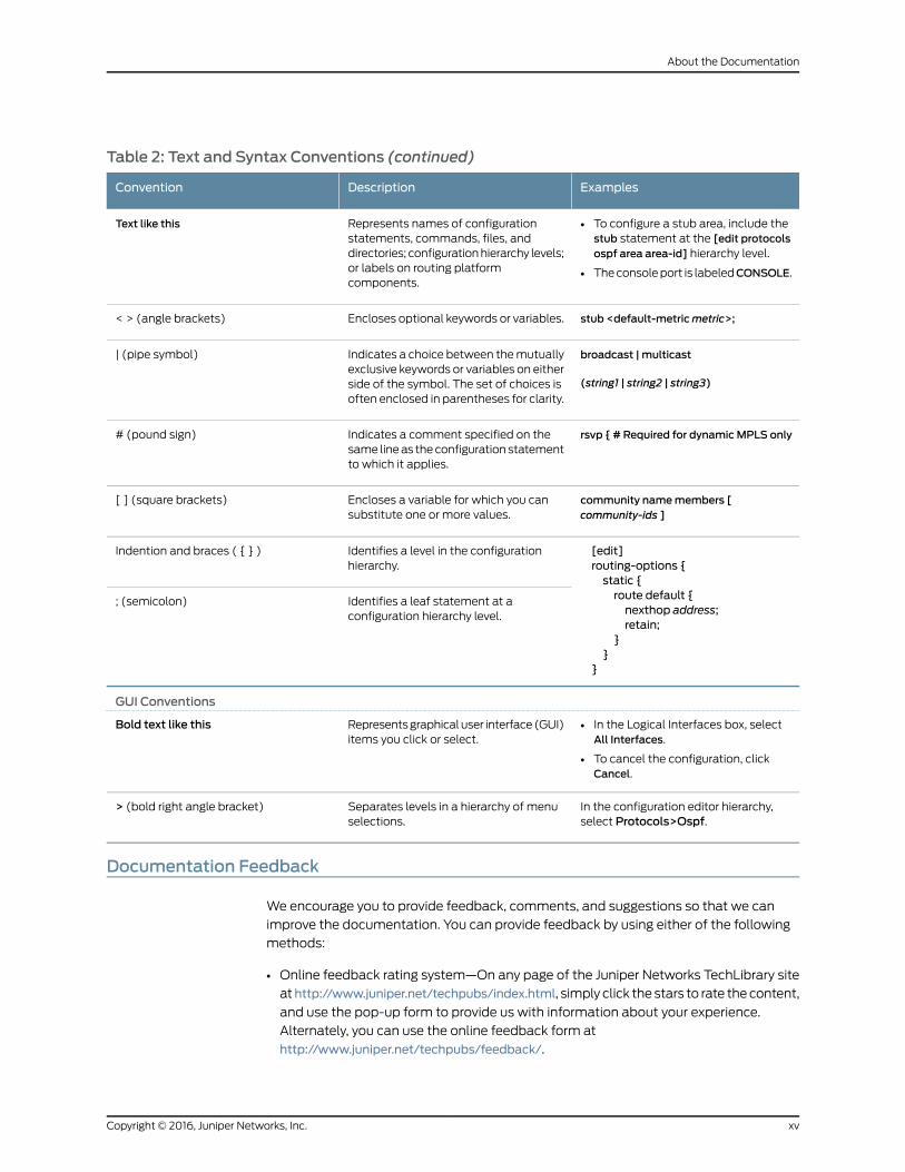
Table 2: Text and Syntax Conventions (continued)
ExamplesDescriptionConvention
• To configure a stub area, include thestub statement at the [edit protocolsospf area area-id] hierarchy level.
• The console port is labeledCONSOLE.
Represents names of configurationstatements, commands, files, anddirectories; configuration hierarchy levels;or labels on routing platformcomponents.
Text like this
stub <default-metricmetric>;Encloses optional keywords or variables.< > (angle brackets)
broadcast | multicast
(string1 | string2 | string3)
Indicates a choice between the mutuallyexclusive keywords or variables on eitherside of the symbol. The set of choices isoften enclosed in parentheses for clarity.
| (pipe symbol)
rsvp { # Required for dynamicMPLS onlyIndicates a comment specified on thesame line as the configuration statementto which it applies.
# (pound sign)
community namemembers [community-ids ]
Encloses a variable for which you cansubstitute one or more values.
[ ] (square brackets)
[edit]routing-options {static {route default {nexthop address;retain;
}}
}
Identifies a level in the configurationhierarchy.
Indention and braces ( { } )
Identifies a leaf statement at aconfiguration hierarchy level.
; (semicolon)
GUI Conventions
• In the Logical Interfaces box, selectAll Interfaces.
• To cancel the configuration, clickCancel.
Represents graphical user interface (GUI)items you click or select.
Bold text like this
In the configuration editor hierarchy,select Protocols>Ospf.
Separates levels in a hierarchy of menuselections.
> (bold right angle bracket)
Documentation Feedback
We encourage you to provide feedback, comments, and suggestions so that we can
improve the documentation. You can provide feedback by using either of the following
methods:
• Online feedback rating system—On any page of the Juniper Networks TechLibrary site
athttp://www.juniper.net/techpubs/index.html, simply click the stars to rate the content,
and use the pop-up form to provide us with information about your experience.
Alternately, you can use the online feedback form at
http://www.juniper.net/techpubs/feedback/.
xvCopyright © 2016, Juniper Networks, Inc.
About the Documentation

• E-mail—Send your comments to [email protected]. Include the document
or topic name, URL or page number, and software version (if applicable).
Requesting Technical Support
Technical product support is available through the Juniper Networks Technical Assistance
Center (JTAC). If you are a customer with an active J-Care or Partner Support Service
support contract, or are covered under warranty, and need post-sales technical support,
you can access our tools and resources online or open a case with JTAC.
• JTAC policies—For a complete understanding of our JTAC procedures and policies,
review the JTAC User Guide located at
http://www.juniper.net/us/en/local/pdf/resource-guides/7100059-en.pdf.
• Product warranties—For product warranty information, visit
http://www.juniper.net/support/warranty/.
• JTAC hours of operation—The JTAC centers have resources available 24 hours a day,
7 days a week, 365 days a year.
Self-Help Online Tools and Resources
For quick and easy problem resolution, Juniper Networks has designed an online
self-service portal called the Customer Support Center (CSC) that provides you with the
following features:
• Find CSC offerings: http://www.juniper.net/customers/support/
• Search for known bugs: http://www2.juniper.net/kb/
• Find product documentation: http://www.juniper.net/techpubs/
• Find solutions and answer questions using our Knowledge Base: http://kb.juniper.net/
• Download the latest versions of software and review release notes:
http://www.juniper.net/customers/csc/software/
• Search technical bulletins for relevant hardware and software notifications:
http://kb.juniper.net/InfoCenter/
• Join and participate in the Juniper Networks Community Forum:
http://www.juniper.net/company/communities/
• Open a case online in the CSC Case Management tool: http://www.juniper.net/cm/
To verify service entitlement by product serial number, use our Serial Number Entitlement
(SNE) Tool: https://tools.juniper.net/SerialNumberEntitlementSearch/
Opening a Casewith JTAC
You can open a case with JTAC on the Web or by telephone.
• Use the Case Management tool in the CSC at http://www.juniper.net/cm/.
• Call 1-888-314-JTAC (1-888-314-5822 toll-free in the USA, Canada, and Mexico).
Copyright © 2016, Juniper Networks, Inc.xvi
SRX650 Services Gateway Hardware Guide
For international or direct-dial options in countries without toll-free numbers, see
http://www.juniper.net/support/requesting-support.html.
xviiCopyright © 2016, Juniper Networks, Inc.
About the Documentation

Copyright © 2016, Juniper Networks, Inc.xviii
SRX650 Services Gateway Hardware Guide

PART 1
Overview
• Introduction on page 3
• Hardware Component Overview on page 11
• Chassis Description on page 17
• Interface Module Description on page 27
• Cooling System Description on page 31
• Power System Description on page 33
1Copyright © 2016, Juniper Networks, Inc.
Copyright © 2016, Juniper Networks, Inc.2
SRX650 Services Gateway Hardware Guide

CHAPTER 1
Introduction
• SRX650 Services Gateway Description on page 3
• SRX650 Services Gateway Features and Functions on page 3
• SRX650 Services Gateway Software Features and Licenses on page 4
• SRX650 Services Gateway Power over Ethernet Overview on page 8
• Accessing the SRX650 Services Gateway on page 10
SRX650 Services Gateway Description
The SRX650 is a mid-range dynamic services gateway that consolidates network
infrastructure and security applications for regional offices, large branch offices, and
small to medium enterprises. The services gateway provides cost-effective, scalable
integration of routing, security, and other mid-range applications for these sites.
The SRX650 Services Gateway has a modular 2U chassis that fits a 19-inch rack with a
depth of approximately 18.1 inches. It contains a rear-pluggable Services and Routing
Engine (SRE) module that provides robust performance for mid-range applications,
particularly routing and security services.
RelatedDocumentation
SRX650 Services Gateway Chassis on page 17•
• Accessing the SRX650 Services Gateway on page 10
• SRX650 Services Gateway Software Features and Licenses on page 4
SRX650 Services Gateway Features and Functions
The SRX650 Services Gateway provides the following features:
• Symmetric Multiprocessing (SMP)-based data forwarding.
• Hardware-based control and data plane separation.
• Four on-board 10/100/1000Base-T Gigabit Ethernet ports.
• A Services and Routing Engine (SRE) with 2 GB DRAM memory configuration, which
contains the management ports (console and USB) for the services gateway.
3Copyright © 2016, Juniper Networks, Inc.

• Support for dual AC and DC power supplies with a redundant configuration in the
chassis. The AC and DC power supplies are hot-swappable. The following power
supplies are supported:
• 645 W AC power supply with or without Power over Ethernet (PoE) support
• 645 W DC power supply with or without PoE support
• Support for 2 GB CompactFlash (CF) storage devices. The SRE contains a hot-pluggable
CF storage device used to upload and download files, and the chassis contains a CF
storage device used to store the operating system. The services gateway supports the
following CF storage devices:
• STEC 2 GB
• Wintec 2 GB
• Junos support for advanced security and routing services on the SRE.
• The SRX650 Services Gateway supports Gigabit-Backplane Physical Interface Modules
(GPIMs). For more details about the supported GPIMs, see the SRX Series Services
Gateways for the Branch Physical Interface Modules Hardware Guide.
RelatedDocumentation
SRX650 Services Gateway Description on page 3•
• Accessing the SRX650 Services Gateway on page 10
• SRX650 Services Gateway Software Features and Licenses on page 4
• SRX650 Services Gateway Chassis on page 17
SRX650 Services Gateway Software Features and Licenses
The services gateway provides the software features listed in Table 3 on page 5.
NOTE: Some software features require the purchase of a separate license.
For information about features that require a license on this services gateway, see the
Installation and Upgrade Guide for Security Devices.
Copyright © 2016, Juniper Networks, Inc.4
SRX650 Services Gateway Hardware Guide

Table 3: Software Features and Licenses
FeatureFeatureCategory
OSPFRouting
BGP
Routing Information Protocol version 1 (RIPv1) and version 2 (RIPv2)
Static routes
Intermediate System-to-Intermediate System (IS-IS)
Connectionless Network Service (CLNS):
• End System-to-Intermediate System (ES-IS) protocol
• IS-IS extensions
• BGP extensions
• Static routes
NOTE: CLNS is available only in packet-based mode.
MPLS:
• Layer 2 and Layer 3 virtual private networks (VPNs)
• VPN routing and forwarding (VRF) table labels
• Traffic engineering protocols such as LDP and RSVP
• Virtual private LAN service (VPLS)
• Multicast VLAN
NOTE: MPLS is available in both packet-based mode and selective packetmode.
• IPv4
• IPv6 routing and forwarding
Internetprotocols
• Static addresses
• Dynamic Host Configuration Protocol (DHCP) 8
IP addressmanagement
5Copyright © 2016, Juniper Networks, Inc.
Chapter 1: Introduction

Table 3: Software Features and Licenses (continued)
FeatureFeatureCategory
Ethernet:
• Media access control (MAC) encapsulation
• 802.1p tagging
• Point-to-Point Protocol over Ethernet (PPPoE)
• Circuit cross-connect (CCC)
• Translational cross-connect (TCC)
Encapsulation
Synchronous Point-to-Point Protocol (PPP)
Frame Relay
High-Level Data Link Control (HDLC)
802.1Q filtering and forwarding
Multilink Frame Relay (MLFR)
Multilink PPP
Line-rate Ethernet switching provided by XPIMs, including support for VLANs,spanning tree, link aggregation, and authentication
Ethernetswitching
Copyright © 2016, Juniper Networks, Inc.6
SRX650 Services Gateway Hardware Guide

Table 3: Software Features and Licenses (continued)
FeatureFeatureCategory
IPsec VPN for site-to-site or remote access encrypted tunnelingSecurity
Antivirus filtering, including full antivirus file-based scanning or Express-AVpacket-based scanning
Antispam and anti-phishing filtering
Web filtering
Content filtering based on file types and types of files within HTTP and HTTPS
Unified threat management (UTM)
Network attack detection
Denial of service (DoS) and distributed denial of service (DDoS) protection
Generic routing encapsulation (GRE), IP-over-IP, and IP Security (IPsec) tunnels
Advanced Encryption Standard (AES) 128-bit, 192-bit, and 256-bit
56-bit Data Encryption Standard (DES) and 168-bit 3DES encryption
MD5 and Secure Hash Algorithm 1 (SHA-1) authentication
Stateful firewall and stateless packet filters
Network Address Translation (NAT)
Junos XML protocol XML application programming interface (API)Systemmanagement
The J-Web browser interface—For services gateway configuration andmanagement
Junos OS command-line interface (CLI)—For services gateway configurationand management through the console through Telnet, or SSH
Simple Network Management Protocol version 1 (SNMPv1), SNMPv2, andSNMPv3
Network and Security Manager (NSM)
J-Flow flow monitoring and accounting
7Copyright © 2016, Juniper Networks, Inc.
Chapter 1: Introduction

Table 3: Software Features and Licenses (continued)
FeatureFeatureCategory
Packet captureTraffic analysis
Real-time performance monitoring (RPM)
System log
The J-Web interface event viewerActivity loggingand monitoring
Traceroute
Supports the following external administrator databases:
• RADIUS/AAA
• TACACS+
AutoinstallationAdministration
Configuration rollback
Button-operated configuration rescue (the CONFIG button)
Confirmation of configuration changes
Software upgrades
Supports the following features for automating network operations andtroubleshooting:
• Commit scripts
• Operation scripts
• Event policies
GPIMs and XPIMs are hot-swappable on the SRX650 Services Gateway.Hot-swappable
LAN bypass ports are not supported on the SRX Series Services Gateways.Bypass ports
RelatedDocumentation
SRX650 Services Gateway Description on page 3•
• SRX650 Services Gateway Features and Functions on page 3
SRX650 Services Gateway Power over Ethernet Overview
Power over Ethernet (PoE) supports the implementation of the IEEE802.3 af and IEE802.3
at standards, which allow both data and electric power to pass over a copper Ethernet
LAN cable.
Copyright © 2016, Juniper Networks, Inc.8
SRX650 Services Gateway Hardware Guide

The SRX650 Services Gateway provides PoE ports, which supply electric power over the
same ports that are used to connect network devices. PoE ports allow you to plug in
devices that require both network connectivity and electric power, such as Voice over IP
(VoIP) and IP phones and wireless access points.
The PoE ports for the SRX650 Services Gateway reside on the individual XPIMs. The
SRX650 Services Gateway supports the following XPIMs with PoE:
• 16-Port Gigabit Ethernet XPIM
• 24-Port Gigabit Ethernet XPIM
The active Services and Routing Engine (SRE) manages the overall system PoE power.
You can configure the services gateway to act as power sourcing equipment to supply
the power to the GPIMs connected on the designated PoE ports.
Table 4 on page 9 lists the SRX650 Services Gateway PoE specifications.
Table 4: SRX650 Services Gateway PoE Specifications
ValuesPower ManagementSchemes
• IEEE802.3 af
• IEEE802.3 at
• Legacy
Supported standards
PoE is supported on the following front panel slots:
• 2
• 4
• 6
• 8
For more information, see “SRX650 Services Gateway FrontPanel” on page 18.
Supported slots
The 645 W AC and 645 W DC power supplies support thefollowing capacities:
• 255 W @PoE on a single power supply, or with redundancyusing the two power supply option
• 510 W @PoE using the two power supply option operatingas nonredundant
Total PoE power sourcingcapacity
31.2 WPer-port power limit
• Static: Power allocated for each interface can be configured
• Class: Power allocation for interfaces is decided based onthe class of powered device connected
Power management modes
For more details about the GPIMs and XPIMs, see the SRX Series Services Gateways for
the Branch Physical Interface Modules Hardware Guide.
9Copyright © 2016, Juniper Networks, Inc.
Chapter 1: Introduction

RelatedDocumentation
SRX650 Services Gateway Gigabit-Backplane Physical Interface Modules on page 27•
• SRX650 Services Gateway Power Supply on page 33
• SRX650 Services Gateway Back Panel on page 24
Accessing the SRX650 Services Gateway
The services gateway runs Junos OS. You can use two user interfaces to monitor, configure,
troubleshoot, and manage the services gateway:
• The J-Web interface: A Web-based graphical interface that allows you to operate a
services gateway without commands. The J-Web interface provides access to all Junos
OS functionality and features.
• Junos OS command-line interface (CLI): Juniper Networks command shell that runs
on top of a UNIX-based operating system kernel. The CLI is a straightforward command
interface. On a single line, you type commands that are executed when you press the
Enter key. The CLI provides command help and command completion.
RelatedDocumentation
• SRX650 Services Gateway Description on page 3
• SRX650 Services Gateway Features and Functions on page 3
• SRX650 Services Gateway Software Features and Licenses on page 4
Copyright © 2016, Juniper Networks, Inc.10
SRX650 Services Gateway Hardware Guide

CHAPTER 2
Hardware Component Overview
• SRX650 Services Gateway Services and Routing Engine 6 on page 11
• SRX650 Services Gateway Boot Devices and Dual-Root Partitioning Scheme on page 14
SRX650 Services Gateway Services and Routing Engine 6
The Services and Routing Engine (SRE) module provides processing power for security
services, routing protocol processes, and other software processes that control the
services gateway interfaces, some of the chassis components, system management,
and user access to the device.
The services gateway must have one SRE installed.
CAUTION: The SRE is not hot-swappable. Youmust power off the servicesgateway before removing or inserting an SRE.
The SRE installs horizontally in the back of the chassis in slots SRE0 or SRE1/SRE1.1. An
SRE weighs 3 lb 13.6 oz (1.75 kg).
NOTE: Slot SRE0 is a full-length slot capable of holding a full slot modulesuch as an SRE. The SRE1 and SRE1.1 slots are capable of holding either twohalf slot modules or one full slot module.
If a slot is not occupied by a card, a blank panel must be installed to shield the empty
slot and to maintain proper cooling of the services gateway.
Figure 1 on page 12 shows the front of the SRE.
11Copyright © 2016, Juniper Networks, Inc.

Figure 1: Services and Routing Engine
SRE 6Services and Routing Engine 6
OFFLINE RESETCONFIG
ALARM POWER STATUSAUX CONSOLE
HASRE
CF ACT
COMPACT FLASH
USB 0 USB 1
g032
705
6
5
42
31 98 10
13
11
127
14
Table 5 on page 12 provides information about the SRE components.
Table 5: Services and Routing Engine Component Descriptions
DescriptionComponentNumber
NOTE: The OFFLINE button is not supported on the SRE for this release.
Gracefully shuts down the SRE for removal when pressed.
NOTE: As of release 10.0, you can only have one SRE installed.
OFFLINE button1
Returns the services gateway to the rescue configuration or the factory defaultconfiguration. For more information, see “Resetting the SRX650 ServicesGateway” on page 133.
RESET CONFIG button2
The ALARM LED has the following indicator colors:
• Red and steadily on indicates a critical alarm, such as failure of a hardwarecomponent or software module, or detection of a firewall attack.
• Amber and steadily on indicates a major alarm, such as low memory (lessthan 10% remaining), session full, maximum number of VPN tunnels reached,HA status change, or redundant group member not found.
• Off indicates that the device is starting up.
NOTE: When the system is up and running, if the ALARM LED is off, it indicatesthat no alarms are present on the device.
ALARM LED3
The POWER LED has the following indicator colors:
• Green and steadily on indicates that the SRE is powered on and functioningnormally.
• Red and steadily on indicates a power supply unit (PSU) has failed.
• Amber and steadily on indicates that the OFFLINE button on the SRE hasbeen pressed and released. The services gateway will gracefully shut down.When the LED goes off, the SRE can be safely removed.
NOTE: The OFFLINE button is not supported on the SRE for this release.
• Off indicates that the SRE is not receiving power.
POWER LED4
Copyright © 2016, Juniper Networks, Inc.12
SRX650 Services Gateway Hardware Guide
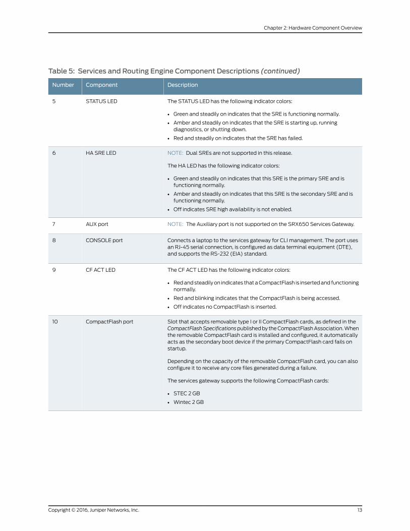
Table 5: Services and Routing Engine Component Descriptions (continued)
DescriptionComponentNumber
The STATUS LED has the following indicator colors:
• Green and steadily on indicates that the SRE is functioning normally.
• Amber and steadily on indicates that the SRE is starting up, runningdiagnostics, or shutting down.
• Red and steadily on indicates that the SRE has failed.
STATUS LED5
NOTE: Dual SREs are not supported in this release.
The HA LED has the following indicator colors:
• Green and steadily on indicates that this SRE is the primary SRE and isfunctioning normally.
• Amber and steadily on indicates that this SRE is the secondary SRE and isfunctioning normally.
• Off indicates SRE high availability is not enabled.
HA SRE LED6
NOTE: The Auxiliary port is not supported on the SRX650 Services Gateway.AUX port7
Connects a laptop to the services gateway for CLI management. The port usesan RJ-45 serial connection, is configured as data terminal equipment (DTE),and supports the RS-232 (EIA) standard.
CONSOLE port8
The CF ACT LED has the following indicator colors:
• Red and steadily on indicates that a CompactFlash is inserted and functioningnormally.
• Red and blinking indicates that the CompactFlash is being accessed.
• Off indicates no CompactFlash is inserted.
CF ACT LED9
Slot that accepts removable type I or II CompactFlash cards, as defined in theCompactFlashSpecificationspublished by the CompactFlash Association. Whenthe removable CompactFlash card is installed and configured, it automaticallyacts as the secondary boot device if the primary CompactFlash card fails onstartup.
Depending on the capacity of the removable CompactFlash card, you can alsoconfigure it to receive any core files generated during a failure.
The services gateway supports the following CompactFlash cards:
• STEC 2 GB
• Wintec 2 GB
CompactFlash port10
13Copyright © 2016, Juniper Networks, Inc.
Chapter 2: Hardware Component Overview

Table 5: Services and Routing Engine Component Descriptions (continued)
DescriptionComponentNumber
The SRE has two USB ports, labeled USB 0 and USB 1, that accept a USB storagedevice. When the USB drive is installed and configured, it automatically acts asthe secondary boot device if the primary CompactFlash card fails on startup.
NOTE: You must install Junos on the USB storage device to use it as thesecondary boot device. The services gateway supports the following USB devices:
• Sandisk Micro Cruzer 2 GB
• Lexar 2 GB
Depending on the capacity of the USB drive, you can also configure it to receivecore files generated during a failure.
USB 0 and USB 1 ports11,12
Small handles on each side of the SRE used to eject it from the chassis (loosencaptive screws first). When installing the SRE into the chassis, use the handlesto ensure a firm connection with the SRE into the backplane receptor.
Ejector handles13
Secures the SRE to the chassis.Captive screws14
RelatedDocumentation
Removing the SRE from the SRX650 Services Gateway on page 139•
• Installing the SRE on the SRX650 Services Gateway on page 77
• SRX650 Services Gateway Back Panel on page 24
SRX650 Services Gateway Boot Devices and Dual-Root Partitioning Scheme
The SRX650 Services Gateway can boot from the following storage media (in order of
priority):
1. Internal CompactFlash card (default; always present)
2. External CompactFlash card (alternate)
3. USB storage key (alternate)
NOTE: If you explicitly boot the services gateway using the CLI and theservices gateway has two USBs installed (one in slot 0 and the second inslot 1), if the USB in slot 0 fails, the booting sequence will not boot from thesecond USB installed in slot 1. Instead, the device will boot using the nextstoragemedia in its storagemediabootingpriority list: InternalCompactFlashcard, then External CompactFlash card.
The dual-root partitions allow the SRX650 Services Gateways to remain functional if
there is file system corruption and facilitates easy recovery of the corrupted file system.
The dual-root partitioning scheme keeps the primary and backup Junos OS images in
two independently bootable root partitions. If the primary root partition becomes
Copyright © 2016, Juniper Networks, Inc.14
SRX650 Services Gateway Hardware Guide
corrupted, the system will be able to boot from the backup Junos OS image located in
the other root partition and remain fully functional.
When the SRX650 Services Gateway powers up, it tries to boot the Junos OS from the
default storage media. If the device fails to boot from the default storage media, it tries
to boot from the alternate storage media. With the dual-root partitioning scheme, the
SRX650 Services Gateway first tries to boot the Junos OS from the primary root partition
and then from the backup root partition on the default storage media. If both primary
and backup root partitions of a media fail to boot, then the device tries to boot from the
next available type of storage media. The SRX650 Services Gateway remains fully
functional even if it boots the Junos OS from the backup root partition of storage media.
NOTE: SRX Series devices that ship from the factory with Junos OS Release10.0 are formatted with the dual-root partitioning scheme.
Existing SRX650 Services Gateway that are running Junos OS Release 9.6 or earlier use
the single-root partitioning scheme. While upgrading these devices to Junos OS Release
10.0, you can choose to format the storage media with dual-root partitions (strongly
recommended) or retain the existing single-root partitioning.
For instructions on upgrading to Junos OS Release 10.0, see the Juniper Networks Junos
10.0 Software Release Notes.
RelatedDocumentation
• Installation Overview for the SRX650 Services Gateway on page 65
• Required Tools and Parts for Installing the SRX650 Services Gateway on page 65
• SRX650 Services Gateway Software Configuration Overview on page 95
15Copyright © 2016, Juniper Networks, Inc.
Chapter 2: Hardware Component Overview

Copyright © 2016, Juniper Networks, Inc.16
SRX650 Services Gateway Hardware Guide
CHAPTER 3
Chassis Description
• SRX650 Services Gateway Chassis on page 17
• SRX650 Services Gateway Front Panel on page 18
• SRX650 Services Gateway Back Panel on page 24
SRX650 Services Gateway Chassis
The SRX650 Services Gateway chassis is a rigid sheet metal structure that houses all
the other hardware components.
Table 6 on page 17 provides information about the physical specifications for the services
gateway.
Table 6: Physical Specifications for the SRX650 Services Gateway
ValuePhysical Specification
2 rack units (U)Chassis height
17.5 in. (44.4 cm)Chassis width
18.2 in. (46.2 cm)Chassis depth
24.96 lb (11.32 kg)Chassis weight (includes one power supply and one SRE6 without any GPIMs)
CAUTION: Before removingor installingcomponentsofa functioningservicesgateway, attach an electrostatic discharge (ESD) strap to an ESD point andplace the other end of the strap around your barewrist. Failure to use an ESDstrap could result in damage to the device.
The services gateway must be connected to earth ground during normal operation. The
protective earthing terminal on the side of the chassis is provided to connect the services
gateway to ground. Additional grounding is provided to an AC-powered services gateway
when you plug its power supply into a grounded AC power receptacle.
17Copyright © 2016, Juniper Networks, Inc.

RelatedDocumentation
SRX650 Services Gateway Description on page 3•
• SRX650 Services Gateway Front Panel on page 18
• SRX650 Services Gateway Back Panel on page 24
• Grounding the SRX650 Services Gateway on page 82
• SRX650 Services Gateway General Safety Guidelines and Warnings on page 161
SRX650 Services Gateway Front Panel
The front panel of the SRX650 Services Gateway includes the following components:
• Front panel LEDs
• Electrostatic discharge (ESD) wrist strap outlet
• Power button
• Four Gigabit Ethernet ports
• Eight Gigabit-Backplane Physical Interface Module (GPIM) slots
Figure 2 on page 18 shows the front panel of the SRX650 Services Gateway.
Figure 2: SRX650 Services Gateway Front Panel
650
g032
700
2 4 6
3 5
7
1
8
9 10
1112
Figure 3 on page 18 shows how the slots on the front panel of the SRX650 Services
Gateway are numbered.
Figure 3: SRX650 Services Gateway Slot Numbers
650
g032
701
875
3
1
6
4
2
Copyright © 2016, Juniper Networks, Inc.18
SRX650 Services Gateway Hardware Guide
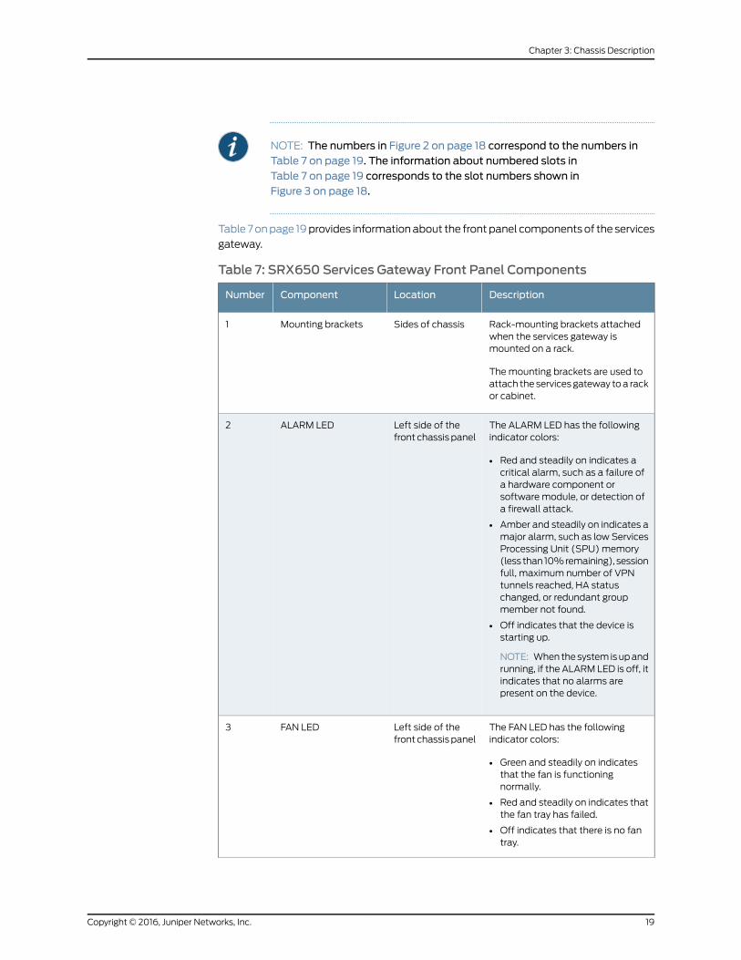
NOTE: The numbers in Figure 2 on page 18 correspond to the numbers inTable 7 on page 19. The information about numbered slots inTable 7 on page 19 corresponds to the slot numbers shown inFigure 3 on page 18.
Table 7 on page 19 provides information about the front panel components of the services
gateway.
Table 7: SRX650 Services Gateway Front Panel Components
DescriptionLocationComponentNumber
Rack-mounting brackets attachedwhen the services gateway ismounted on a rack.
The mounting brackets are used toattach the services gateway to a rackor cabinet.
Sides of chassisMounting brackets1
The ALARM LED has the followingindicator colors:
• Red and steadily on indicates acritical alarm, such as a failure ofa hardware component orsoftware module, or detection ofa firewall attack.
• Amber and steadily on indicates amajor alarm, such as low ServicesProcessing Unit (SPU) memory(less than 10% remaining), sessionfull, maximum number of VPNtunnels reached, HA statuschanged, or redundant groupmember not found.
• Off indicates that the device isstarting up.
NOTE: When the system is up andrunning, if the ALARM LED is off, itindicates that no alarms arepresent on the device.
Left side of thefront chassis panel
ALARM LED2
The FAN LED has the followingindicator colors:
• Green and steadily on indicatesthat the fan is functioningnormally.
• Red and steadily on indicates thatthe fan tray has failed.
• Off indicates that there is no fantray.
Left side of thefront chassis panel
FAN LED3
19Copyright © 2016, Juniper Networks, Inc.
Chapter 3: Chassis Description

Table7:SRX650ServicesGatewayFrontPanelComponents (continued)
DescriptionLocationComponentNumber
The SRE/ACE 1.0 LED has thefollowing indicator colors:
• Green and steadily on indicates:
• SRE1 is functioning normally.
• ACE 1.0 half slot is functioningnormally.
• ACE 1 full slot is functioningnormally.
• Amber and steadily on indicatesSRE1/ACE1 (full slot) or ACE 1.0(half slot) is initializing, performingdiagnostics, or going down.
• Red and on steadily indicatesSRE1/ACE1 (full slot) or ACE 1.0(half slot) failure.
• Off indicates SRE/ACE1 slot isempty.
NOTE: ACE modules will besupported in a future release.
Left side of thefront chassis panel
SRE/ACE LED 1.04
For personal safety, while working onthe services gateway, use the ESDoutlet to plug in an ESD groundingstrap to prevent your body fromsending static charges to the servicesgateway.
Left side of thefront chassis panel
Electrostatic discharge(ESD) outlet
5
The Gigabit Ethernet ports have thefollowing characteristics:
• Use an RJ-45 connector.
• Operate in full-duplex andhalf-duplex modes.
• Support flow control.
• Support autonegotiation.
The Gigabit Ethernet ports can beused to:
• Function as front-end networkports.
• Provide LAN and WANconnectivity to hubs, switches,local servers, and workstations.
• Forward incoming data packets tothe services gateway.
• Receive outgoing data packetsfrom the services gateway.
Left side of thefront chassis panel
4 fixed Gigabit Ethernetports:
• labeled Port 0/0
• labeled Port 0/1
• labeled Port 0/2
• labeled Port 0/3
Provides link speeds of10/100/1000 Mbps.
6
Copyright © 2016, Juniper Networks, Inc.20
SRX650 Services Gateway Hardware Guide
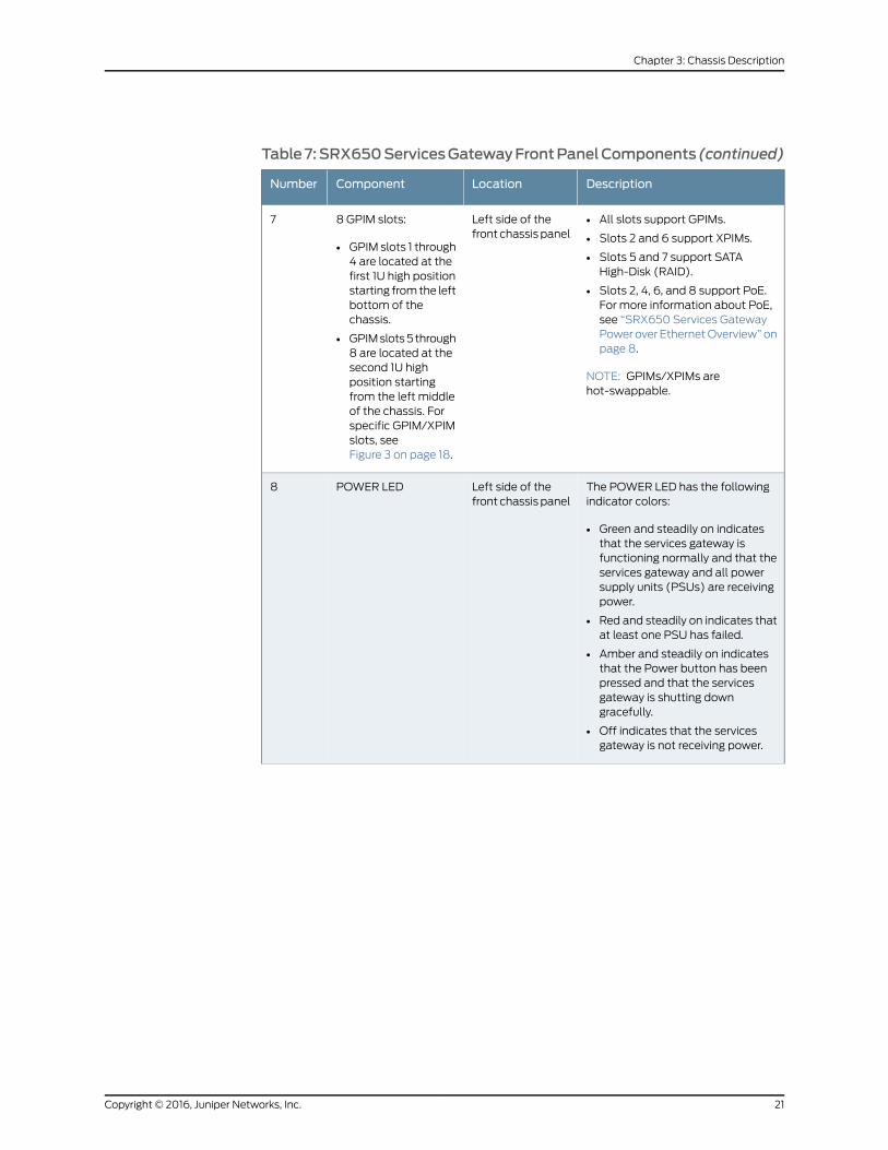
Table7:SRX650ServicesGatewayFrontPanelComponents (continued)
DescriptionLocationComponentNumber
• All slots support GPIMs.
• Slots 2 and 6 support XPIMs.
• Slots 5 and 7 support SATAHigh-Disk (RAID).
• Slots 2, 4, 6, and 8 support PoE.For more information about PoE,see “SRX650 Services GatewayPower over Ethernet Overview” onpage 8.
NOTE: GPIMs/XPIMs arehot-swappable.
Left side of thefront chassis panel
8 GPIM slots:
• GPIM slots 1 through4 are located at thefirst 1U high positionstarting from the leftbottom of thechassis.
• GPIM slots 5 through8 are located at thesecond 1U highposition startingfrom the left middleof the chassis. Forspecific GPIM/XPIMslots, seeFigure 3 on page 18.
7
The POWER LED has the followingindicator colors:
• Green and steadily on indicatesthat the services gateway isfunctioning normally and that theservices gateway and all powersupply units (PSUs) are receivingpower.
• Red and steadily on indicates thatat least one PSU has failed.
• Amber and steadily on indicatesthat the Power button has beenpressed and that the servicesgateway is shutting downgracefully.
• Off indicates that the servicesgateway is not receiving power.
Left side of thefront chassis panel
POWER LED8
21Copyright © 2016, Juniper Networks, Inc.
Chapter 3: Chassis Description

Table7:SRX650ServicesGatewayFrontPanelComponents (continued)
DescriptionLocationComponentNumber
The High Availability (HA SYS) LEDhas the following indicator colors:
• Green and steadily on indicatesthat all configured HA links areavailable.
• Red and steadily on indicates thatthe HA links are not working asexpected and a cluster membermight be missing or unreachable.
• Amber and steadily on indicatesthat some configured HA links aredown, but enough links are stillactive for full HA functionality. Inthis situation, performance mightbe reduced, current bandwidthcould cause packet drops, or asingle point of failure might nowexist.
• Off indicates that HA is notenabled.
Left side of thefront chassis panel
HA SYS LED9
The Services and Routing Engine(SRE) 0 LED has the followingindicator colors:
• Green and steadily on indicatesSRE0 is functioning normally.
• Amber and steadily on indicatesSRE0 is initializing, performingdiagnostics, or going down.
• Red and steadily on indicatesSRE0 failure.
• Off indicates SRE0 slot is empty.
Left side of thefront chassis panel
SRE LED 010
Copyright © 2016, Juniper Networks, Inc.22
SRX650 Services Gateway Hardware Guide
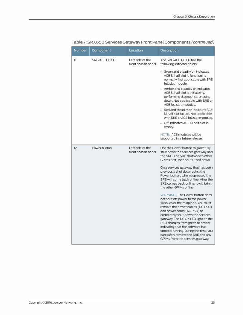
Table7:SRX650ServicesGatewayFrontPanelComponents (continued)
DescriptionLocationComponentNumber
The SRE/ACE 1.1 LED has thefollowing indicator colors:
• Green and steadily on indicatesACE 1.1 half slot is functioningnormally. Not applicable with SREfull slot module.
• Amber and steadily on indicatesACE 1.1 half slot is initializing,performing diagnostics, or goingdown. Not applicable with SRE orACE full slot modules.
• Red and steadily on indicates ACE1.1 half slot failure. Not applicablewith SRE or ACE full slot modules.
• Off indicates ACE 1.1 half slot isempty.
NOTE: ACE modules will besupported in a future release.
Left side of thefront chassis panel
SRE/ACE LED 1.111
Use the Power button to gracefullyshut down the services gateway andthe SRE. The SRE shuts down otherGPIMs first, then shuts itself down.
On a services gateway that has beenpreviously shut down using thePower button, when depressed theSRE will come back online. After theSRE comes back online, it will bringthe other GPIMs online.
WARNING: The Power button doesnot shut off power to the powersupplies or the midplane. You mustremove the power cables (DC PSU)and power cords (AC PSU) tocompletely shut down the servicesgateway. The DC OK LED light on thePSU changes from green to amberindicating that the software hasstopped running. During this time, youcan safely remove the SRE and anyGPIMs from the services gateway.
Left side of thefront chassis panel
Power button12
23Copyright © 2016, Juniper Networks, Inc.
Chapter 3: Chassis Description
RelatedDocumentation
SRX650 Services Gateway Chassis on page 17•
• SRX650 Services Gateway Back Panel on page 24
• SRX650 Services Gateway Services and Routing Engine 6 on page 11
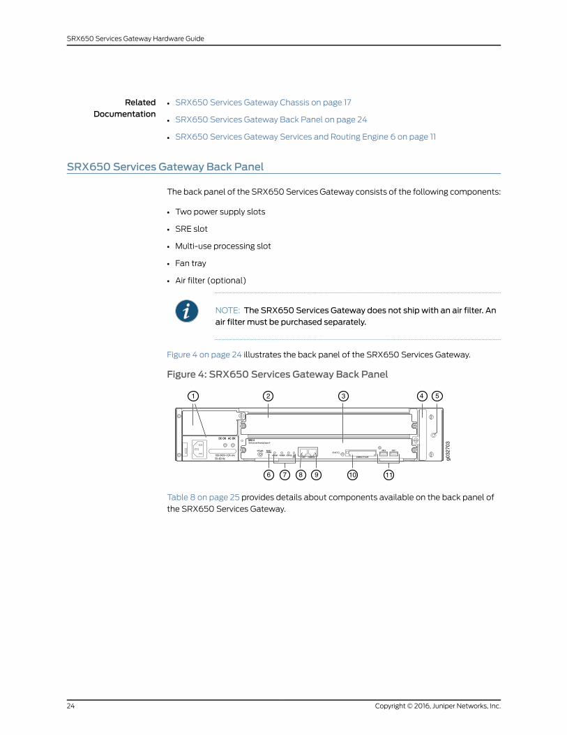
SRX650 Services Gateway Back Panel
The back panel of the SRX650 Services Gateway consists of the following components:
• Two power supply slots
• SRE slot
• Multi-use processing slot
• Fan tray
• Air filter (optional)
NOTE: The SRX650 Services Gateway does not ship with an air filter. Anair filter must be purchased separately.
Figure 4 on page 24 illustrates the back panel of the SRX650 Services Gateway.
Figure 4: SRX650 Services Gateway Back Panel
DC OK AC OK
g032
703
1 2 3
11
4 5
1076 8 9
Table 8 on page 25 provides details about components available on the back panel of
the SRX650 Services Gateway.
Copyright © 2016, Juniper Networks, Inc.24
SRX650 Services Gateway Hardware Guide
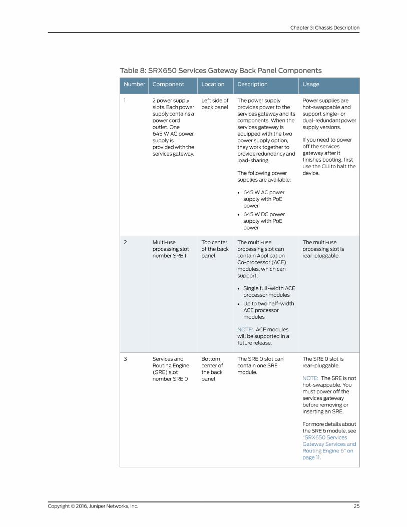
Table 8: SRX650 Services Gateway Back Panel Components
UsageDescriptionLocationComponentNumber
Power supplies arehot-swappable andsupport single- ordual-redundant powersupply versions.
If you need to poweroff the servicesgateway after itfinishes booting, firstuse the CLI to halt thedevice.
The power supplyprovides power to theservices gateway and itscomponents. When theservices gateway isequipped with the twopower supply option,they work together toprovide redundancy andload-sharing.
The following powersupplies are available:
• 645 W AC powersupply with PoEpower
• 645 W DC powersupply with PoEpower
Left side ofback panel
2 power supplyslots. Each powersupply contains apower cordoutlet. One645 W AC powersupply isprovided with theservices gateway.
1
The multi-useprocessing slot isrear-pluggable.
The multi-useprocessing slot cancontain ApplicationCo-processor (ACE)modules, which cansupport:
• Single full-width ACEprocessor modules
• Up to two half-widthACE processormodules
NOTE: ACE moduleswill be supported in afuture release.
Top centerof the backpanel
Multi-useprocessing slotnumber SRE 1
2
The SRE 0 slot isrear-pluggable.
NOTE: The SRE is nothot-swappable. Youmust power off theservices gatewaybefore removing orinserting an SRE.
For more details aboutthe SRE 6 module, see“SRX650 ServicesGateway Services andRouting Engine 6” onpage 11.
The SRE 0 slot cancontain one SREmodule.
Bottomcenter ofthe backpanel
Services andRouting Engine(SRE) slotnumber SRE 0
3
25Copyright © 2016, Juniper Networks, Inc.
Chapter 3: Chassis Description

Table8:SRX650ServicesGatewayBackPanelComponents (continued)
UsageDescriptionLocationComponentNumber
Cools the servicesgateway and itscomponents. The fantray is hot-swappable.
Contains four 80 mmfans.
Right of theback panel
Fan tray (built-incomponent)
4
Keeps the servicesgateway and itscomponents free fromdust particles. The airfilter ishot-swappable.
Contains one air filter.Right of theback panel,behind thefan tray
Air filter
NOTE: TheSRX650 ServicesGateway doesnot ship with anair filter. An airfilter must bepurchasedseparately.
5
RelatedDocumentation
• SRX650 Services Gateway Chassis on page 17
• SRX650 Services Gateway Front Panel on page 18
• SRX650 Services Gateway Power Supply on page 33
Copyright © 2016, Juniper Networks, Inc.26
SRX650 Services Gateway Hardware Guide

CHAPTER 4
Interface Module Description
• SRX650 Services Gateway Gigabit-Backplane Physical Interface Modules on page 27
SRX650 Services Gateway Gigabit-Backplane Physical InterfaceModules
A Gigabit-Backplane Physical Interface Module (GPIM) is a network interface card (NIC)
that installs in the front slots of the services gateway to provide physical connections to
a LAN or a WAN. The GPIM receives incoming packets from a network and transmits
outgoing packets to a network. These modules will complement the onboard Ethernet
interfaces to extend the types and port counts of network connections for the LAN or
WAN.
Interface Module Terminology:
• GPIM—The Gigabit-Backplane Interface Module (GPIM) includes standard GPIMs that
are installed in a single-high, single-wide GPIM slot that has gigabit connectivity to the
system backplane.
• XPIM—The XPIM can be installed only in the 20-gigabit GPIM slots (slots 2 and 6 on
the front panel). It may be:
• A single-high, single-wide LAN switch GPIM that uses one slot
• A double-high, single-wide LAN switch GPIM that uses two standard slots vertically
• A double-high, double-wide LAN switch GPIM that uses two standard slots vertically
and two standard slots horizontally
NOTE: When installing the24-PortGigabit EthernetXPIM,whichuses fourslots, youmust install it in the 20-gigabit GPIM slots 2 and 6, which referto the bottom four slots 1 to 4, or the top four slots 5 to 8.
Figure 5 on page 28 shows how the slots on the front panel of the SRX650 Services
Gateway are numbered.
27Copyright © 2016, Juniper Networks, Inc.

Figure 5: SRX650 Services Gateway Slot Numbers
650
g032
701
875
3
1
6
4
2
CAUTION: GPIMs are hot-swappable.
For more details about the supported GPIMs and XPIMs, and the minimum supported
Junos OS release, see theSRXSeriesServicesGateway InterfaceModulesandCompatibility.
For more information about how to install and configure GPIMs, refer to the SRX Series
Services Gateways for the Branch Physical Interface Modules Hardware Guide.
Figure 6 on page 28, Figure 7 on page 28, and Figure 8 on page 28 show the three form
factors for the services gateway GPIMs.
Figure 6: Example of a Standard GPIM (Installs in One Standard Slot)
g032
721
Figure 7: Example of a Double-High, Single-Wide XPIMg0
3272
3
Figure 8: Example of a Double-High, Double-Wide XPIM
g032
724
Since the services gateway GPIMs communicate with the backplane at various
performance levels, you must install them in the correct slots.
RelatedDocumentation
• SRX650 Services Gateway Front Panel on page 18
• SRX650 Services Gateway Power over Ethernet Overview on page 8
• Installing a Double-High, Double-Wide Gigabit-Backplane Physical Interface Module on
the SRX Series Services Gateway
Copyright © 2016, Juniper Networks, Inc.28
SRX650 Services Gateway Hardware Guide

• SRX Series Services Gateways for the Branch Physical Interface Modules Reference
29Copyright © 2016, Juniper Networks, Inc.
Chapter 4: Interface Module Description

Copyright © 2016, Juniper Networks, Inc.30
SRX650 Services Gateway Hardware Guide

CHAPTER 5
Cooling System Description
• SRX650 Services Gateway Cooling System on page 31
SRX650 Services Gateway Cooling System
The fan controller is the cooling system component provided in the SRX650 Services
Gateway to keep all components within the acceptable temperature range.
The services gateway has a single fan tray that contains four 80 mm fans.
The fan controller constantly monitors the temperature of the services gateway and all
modules (SRE or GPIMs) installed in the device at any given time. Under normal operating
conditions, the fans function at lower than full speed.
If any one of the four fans fails, the services gateway generates a warning but keeps the
system running. If the temperature keeps rising, the services gateway lowers the power
consumption by reducing the performance or shutting down some of the chassis
components. However, if the ambient maximum temperature specification exceeds the
warning limit and the system cannot be adequately cooled, then the services gateway
shuts down the system and hardware components completely.
RelatedDocumentation
• SRX650 Services Gateway Chassis on page 17
• SRX650 Services Gateway Front Panel on page 18
• SRX650 Services Gateway Back Panel on page 24
• SRX650 Services Gateway Power Supply on page 33
31Copyright © 2016, Juniper Networks, Inc.

Copyright © 2016, Juniper Networks, Inc.32
SRX650 Services Gateway Hardware Guide

CHAPTER 6
Power System Description
• SRX650 Services Gateway Power Supply on page 33
SRX650 Services Gateway Power Supply
The SRX650 Services Gateway uses either one AC or one DC power supply unit (PSU).
The services gateway is equipped with one AC power supply (see Figure 9 on page 33).
A second PSU is optional (sold separately). A second PSU can be used to meet power
requirements exceeding the wattage provided by a single PSU in a nonredundant
configuration by using two power supplies in a system using more power than a single
PSU provides. A second AC or DC power supply can be used with its matching type of
power supply to provide redundancy and load-sharing to the services gateway and its
components. If one power supply fails or is removed, the remaining power supply
redistributes the electrical load without interruption. The services gateway reassesses
the power required to support its configuration and issues errors if the available power
is insufficient. See Figure 10 on page 34 for a diagram of the DC power supply.
CAUTION: Do notmix AC and DC power supplies within the same servicesgateway. Damage to the devicemight occur.
All power supplies are hot-swappable and support single or dual redundant power supply
versions. Each power supply is cooled by the system’s fans.
Figure 9: Single AC Power Supply for the SRX650 Services Gateway
g032
709
33Copyright © 2016, Juniper Networks, Inc.

Figure 10: Single DC Power Supply for the SRX650 Services Gateway
The power supplies produce and distribute different output voltages to the services
gateway components according to their voltage requirements.
The available power supply components are listed in Table 9 on page 34.
Table 9: Component Power Output/Consumption
Output/ConsumptionPower Supply
This power supply can provide:
• 390 W @12 V
• 255 W @PoE on a single power supply, or withredundancy using the two power supply option
• 510 W @PoE using the two power supply optionoperating as nonredundant
NOTE: Using the two power supply optionoperating as nonredundant for up to 510 W @PoEpower, the administrator has the ability to prioritizethe PoE ports that will receive power if an outageshould occur to either the power source or to oneof the power supplies.
645 W AC power supply
This power supply can provide:
• 390 W @12 V
• 255 W @PoE on a single power supply, or withredundancy using the two power supply option
• 510 W @PoE using the two power supply optionoperating as nonredundant
NOTE: Using the two power supply optionoperating as nonredundant for up to 510 W @PoEpower, the administrator has the ability to prioritizethe PoE ports that will receive power if an outageshould occur to either the power source or to oneof the power supplies.
645 W DC power supply
Copyright © 2016, Juniper Networks, Inc.34
SRX650 Services Gateway Hardware Guide

RelatedDocumentation
• SRX650 Services Gateway Chassis on page 17
• SRX650 Services Gateway Front Panel on page 18
• SRX650 Services Gateway Back Panel on page 24
• SRX650 Services Gateway Cooling System on page 31
• Troubleshooting the Power System on the SRX650 Services Gateway on page 129
35Copyright © 2016, Juniper Networks, Inc.
Chapter 6: Power System Description

Copyright © 2016, Juniper Networks, Inc.36
SRX650 Services Gateway Hardware Guide

PART 2
Site Planning and Specifications
• Planning and Preparing the Site on page 39
• Rack Requirements on page 45
• Cabinet Requirements on page 53
• Power Requirements and Specifications on page 55
• Cable Specifications and Pinouts on page 61
37Copyright © 2016, Juniper Networks, Inc.

Copyright © 2016, Juniper Networks, Inc.38
SRX650 Services Gateway Hardware Guide

CHAPTER 7
Planning and Preparing the Site
• Site Preparation Checklist for the SRX650 Services Gateway on page 39
• General Site Installation Guidelines for the SRX650 Services Gateway on page 41
• SRX650 Services Gateway Environmental Specifications on page 42
Site Preparation Checklist for the SRX650 Services Gateway
The checklist in Table 10 on page 39 summarizes the tasks you need to perform when
preparing a site for installing the SRX650 Services Gateway.
Table 10: Site Preparation Checklist for SRX650 Services GatewayInstallation
NotesDatePerformedByAdditional InformationItem or Task
Power
“SRX650 ServicesGateway Electrical WiringGuidelines” on page 55
Measuredistancebetweenexternalpower sourcesand deviceinstallationsite.
“Grounding the SRX650Services Gateway” onpage 82
Locate sitesfor connectionof systemgrounding.
“SRX650 ServicesGateway AC PowerSupply ElectricalSpecifications” onpage 58 and “SRX650Services Gateway DCPower Supply ElectricalSpecifications” onpage 58
Calculate thepowerconsumptionandrequirements.
39Copyright © 2016, Juniper Networks, Inc.

Table 10: Site Preparation Checklist for SRX650 Services GatewayInstallation (continued)
NotesDatePerformedByAdditional InformationItem or Task
Environment
“SRX650 ServicesGateway EnvironmentalSpecifications” onpage 42
Verify thatenvironmentalfactors suchastemperatureand humiditydo not exceeddevicetolerances.
Rack Installation
“SRX650 ServicesGateway Rack Size andStrength Requirements”on page 49
Verify thatyour rackmeets theminimumrequirements.
“SRX650 ServicesGateway Spacing ofMounting Bracket andFlange Holes” on page 49
Plan racklocation,includingrequired spaceclearances.
“Connecting the SRX650Services Gateway to theBuilding Structure” onpage 71
Secure therack to thefloor andbuildingstructure.
Cabinet Installation
“SRX650 ServicesGateway Cabinet Sizeand ClearanceRequirements” onpage 53
Verify thatyour cabinetmeets theminimumrequirements.
“SRX650 ServicesGateway Cabinet AirflowRequirements” onpage 54
Plan thecabinetlocation,includingrequired spaceclearances.
Cables
Copyright © 2016, Juniper Networks, Inc.40
SRX650 Services Gateway Hardware Guide

Table 10: Site Preparation Checklist for SRX650 Services GatewayInstallation (continued)
NotesDatePerformedByAdditional InformationItem or Task
“Interface Cabling andWiring Specifications forthe SRX650 ServicesGateway” on page 61
Acquire cablesandconnectors.
Review themaximumdistanceallowed foreach cable.Choose thelength ofcable basedon thedistancebetween thehardwarecomponentsbeingconnected.
Plan the cablerouting andmanagement.
RelatedDocumentation
SRX650 Services Gateway Chassis on page 17•
• Installation Overview for the SRX650 Services Gateway on page 65
• General Site Installation Guidelines for the SRX650 Services Gateway on page 41
General Site Installation Guidelines for the SRX650 Services Gateway
The following precautions help you plan an acceptable operating environment for your
SRX650 Services Gateway and avoid environmentally caused equipment failures:
• For the cooling system to function properly, the airflow around the chassis must be
unrestricted. Allow sufficient clearance between the front and back of the chassis and
adjacent equipment. Ensure that there is adequate circulation in the installation location.
• Follow the ESD procedures to avoid damaging equipment. Static discharge can cause
components to fail completely or intermittently over time. For more information, see
“Preventing Electrostatic Discharge Damage to the SRX650 Services Gateway” on
page 164.
• Ensure that the blank panels are installed into empty slots to prevent any interruption
or reduction in the flow of air across internal components.
41Copyright © 2016, Juniper Networks, Inc.
Chapter 7: Planning and Preparing the Site

NOTE: Install theservicesgatewayonly in restrictedareas, suchasdedicatedequipment roomsandequipmentclosets, inaccordancewithArticles 110–16,110–17, and 110–18 of the National Electrical Code, ANSI/NFPA 70.
RelatedDocumentation
SRX650 Services Gateway Chassis on page 17•
• SRX650 Services Gateway Cabinet Size and Clearance Requirements on page 53
• SRX650 Services Gateway Rack Size and Strength Requirements on page 49
• Clearance Requirements for Airflow and Hardware Maintenance of the SRX650 Services
Gateway on page 50
SRX650 Services Gateway Environmental Specifications
Table 11 on page 42 provides the required environmental conditions for normal SRX650
Services Gateway operations. In addition, the site must be as dust-free as possible
because dust can clog air intake vents and filters, reducing the efficiency of the cooling
system.
Table 11: SRX650 Services Gateway Environmental Specifications
ValueDescription
No performance degradation to 13,000 ft (3962.4 m)Altitude
Normal operation ensured in relative humidity range of 5% to 90%,noncondensing
Relative humidity
Normal operation ensured in temperature range of 32°F (0°C) to 104°F(40°C)
Nonoperating storage temperature in shipping container: –40°F(–40°C) to 158°F (70°C)
Temperature
Designed to meet Telcordia Technologies Zone 4 earthquakerequirements
Seismic
AC power: 4400 BTU/hour
DC power with one 645 W power supply unit: 2200 BTU/hour
DC power with two 645 W power supply units, nonredundant: 4400BTU/hour
NOTE: These specifications are estimates and subject to change.
Maximum thermaloutput
NOTE: Install theservicesgatewayonly in restrictedareas, suchasdedicatedequipment roomsandequipmentclosets, inaccordancewithArticles 110–16,110–17, and 110–18 of the National Electrical Code, ANSI/NFPA 70.
Copyright © 2016, Juniper Networks, Inc.42
SRX650 Services Gateway Hardware Guide
RelatedDocumentation
• SRX650 Services Gateway General Safety Guidelines and Warnings on page 161
• Routine Maintenance Procedures for the SRX650 Services Gateway on page 121
43Copyright © 2016, Juniper Networks, Inc.
Chapter 7: Planning and Preparing the Site

Copyright © 2016, Juniper Networks, Inc.44
SRX650 Services Gateway Hardware Guide

CHAPTER 8
Rack Requirements
• Rack-Mounting Requirements and Warnings on page 45
• SRX650 Services Gateway Rack Size and Strength Requirements on page 49
• SRX650 Services Gateway Spacing of Mounting Bracket and Flange Holes on page 49
• Clearance Requirements for Airflow and Hardware Maintenance of the SRX650 Services
Gateway on page 50
Rack-Mounting Requirements andWarnings
Ensure that the equipment rack into which the services gateway is installed is evenly and
securely supported to avoid hazardous conditions that could result from uneven
mechanical loading.
WARNING: To prevent bodily injury whenmounting or servicing the servicesgateway in a rack, take the following precautions to ensure that the systemremains stable. The following directives helpmaintain your safety:
• The services gatewaymust be installed in a rack that is secured to thebuilding structure.
• The services gateway should bemounted at the bottom of the rack if it isthe only unit in the rack.
• Whenmounting the services gateway in a partially filled rack, load the rackfrom the bottom to the topwith the heaviest component at the bottom ofthe rack.
• If the rack is providedwith stabilizing devices, install the stabilizers beforemounting or servicing the services gateway in the rack.
WaarschuwingOm lichamelijk letsel te voorkomenwanneer u dit toestel ineen rekmonteert of het daar een servicebeurt geeft, moet u specialevoorzorgsmaatregelen nemen om ervoor te zorgen dat het toestel stabielblijft. De onderstaande richtlijnen worden verstrekt om uw veiligheid teverzekeren:
45Copyright © 2016, Juniper Networks, Inc.

• De Juniper Networks services gatewaymoet in een stellage wordengeïnstalleerd die aan een bouwsel is verankerd.
• Dit toestel dient onderaan in het rek gemonteerd teworden als het toestelhet enige in het rek is.
• Wanneer u dit toestel in een gedeeltelijk gevuld rekmonteert, dient u hetrekvanonderennaarboven te ladenmethet zwaarsteonderdeelonderaanin het rek.
• Als het rek voorzien is van stabiliseringshulpmiddelen, dient u destabilisatoren temonteren voordat u het toestel in het rekmonteert of hetdaar een servicebeurt geeft.
VaroitusKun laiteasetetaan telineeseen taihuolletaansenollessa telineessä,onnoudatettavaerityisiävarotoimia järjestelmänvakavuudensäilyttämiseksi,jotta vältytään loukkaantumiselta. Noudata seuraavia turvallisuusohjeita:
• Juniper Networks services gateway on asennettava telineeseen, joka onkiinnitetty rakennukseen.
• Jos telineessä ei ole muita laitteita, aseta laite telineen alaosaan.
• Jos laite asetetaan osaksi täytettyyn telineeseen, aloita kuormittaminensen alaosasta kaikkein raskaimmalla esineellä ja siirry sitten sen yläosaan.
• Jos telinettä varten on vakaimet, asenna ne ennen laitteen asettamistatelineeseen tai sen huoltamista siinä.
Attention Pour éviter toute blessure corporelle pendant les opérations demontage ou de réparation de cette unité en casier, il convient de prendre desprécautions spécialesafindemaintenir la stabilité du système. Lesdirectivesci-dessous sont destinées à assurer la protection du personnel:
• Le rack sur lequel estmonté le JuniperNetworks services gatewaydoit êtrefixé à la structure du bâtiment.
• Si cette unité constitue la seule unitémontéeencasier, elle doit êtreplacéedans le bas.
• Si cette unité est montée dans un casier partiellement rempli, charger lecasier de bas en haut en plaçant l'élément le plus lourd dans le bas.
• Si lecasier estéquipédedispositifs stabilisateurs, installer les stabilisateursavant demonter ou de réparer l'unité en casier.
WarnungZurVermeidungvonKörperverletzungbeimAnbringenoderWartendieser Einheit in einemGestell müssen Sie besondere Vorkehrungen treffen,um sicherzustellen, daß das System stabil bleibt. Die folgenden Richtliniensollen zur Gewährleistung Ihrer Sicherheit dienen:
Copyright © 2016, Juniper Networks, Inc.46
SRX650 Services Gateway Hardware Guide

• Der Juniper Networks services gatewaymuß in einemGestell installiertwerden, das in der Gebäudestruktur verankert ist.
• Wenn diese Einheit die einzige im Gestell ist, sollte sie unten im Gestellangebracht werden.
• Bei Anbringung dieser Einheit in einem zum Teil gefüllten Gestell ist dasGestell von unten nach oben zu laden, wobei das schwerste Bauteil untenim Gestell anzubringen ist.
• Wird das Gestell mit Stabilisierungszubehör geliefert, sind zuerst dieStabilisatoren zu installieren, bevor Sie die Einheit im Gestell anbringenoder sie warten.
AvvertenzaPerevitare infortuni fisici durante ilmontaggioo lamanutenzionedi questa unità in un supporto, occorre osservare speciali precauzioni pergarantire che il sistema rimanga stabile. Le seguenti direttive vengono forniteper garantire la sicurezza personale:
• Il Juniper Networks services gateway deve essere installato in un telaio, ilquale deve essere fissato alla struttura dell'edificio.
• Questa unità deve venire montata sul fondo del supporto, se si trattadell'unica unità damontare nel supporto.
• Quando questa unità vienemontata in un supporto parzialmente pieno,caricare il supporto dal basso all'alto, con il componente più pesantesistemato sul fondo del supporto.
• Se il supporto è dotato di dispositivi stabilizzanti, installare tali dispositiviprimadimontareodiprocedereallamanutenzionedell'unitànel supporto.
AdvarselUnngå fysiske skader under montering eller reparasjonsarbeid pådenne enheten når den befinner seg i et kabinett. Vær nøyemed at systemeter stabilt. Følgende retningslinjer er gitt for å verne om sikkerheten:
• JuniperNetworksservicesgatewaymå installeres i et stativ somer forankrettil bygningsstrukturen.
• Denne enheten børmonteres nederst i kabinettet hvis dette er den enesteenheten i kabinettet.
• Vedmontering av denne enheten i et kabinett som er delvis fylt, skalkabinettet lastes frabunnenogoppmeddentyngstekomponentennedersti kabinettet.
• Hvis kabinettet er utstyrt med stabiliseringsutstyr, skal stabilisatoreneinstalleres før montering eller utføring av reparasjonsarbeid på enheten ikabinettet.
Aviso Para se prevenir contra danos corporais aomontar ou reparar estaunidade numaestante, deverá tomar precauções especiais para se certificar
47Copyright © 2016, Juniper Networks, Inc.
Chapter 8: Rack Requirements
de que o sistema possui um suporte estável. As seguintes directrizesajudá-lo-ão a efectuar o seu trabalho com segurança:
• O Juniper Networks services gateway deverá ser instalado numaprateleirafixa à estrutura do edificio.
• Esta unidade deverá ser montada na parte inferior da estante, caso sejaesta a única unidade a ser montada.
• Aomontar esta unidade numa estante parcialmente ocupada, coloque ositensmais pesados na parte inferior da estante, arrumando-os de baixopara cima.
• Se a estante possuir um dispositivo de estabilização, instale-o antes demontar ou reparar a unidade.
¡Atención! Para evitar lesiones durante el montaje de este equipo sobre unbastidor, o posteriormente durante sumantenimiento, se debeponermuchocuidado en que el sistema quede bien estable. Para garantizar su seguridad,proceda según las siguientes instrucciones:
• El Juniper Networks services gateway debe instalarse en un bastidor fijadoa la estructura del edificio.
• Colocar el equipo en la parte inferior del bastidor, cuando sea la únicaunidad en el mismo.
• Cuandoesteequiposevayaa instalarenunbastidorparcialmenteocupado,comenzar la instalación desde la parte inferior hacia la superior colocandoel equipomás pesado en la parte inferior.
• Si el bastidor dispone de dispositivos estabilizadores, instalar éstos antesdemontaroprocederalmantenimientodel equipo instaladoenelbastidor.
Varning! För att undvika kroppsskada när du installerar eller utförunderhållsarbete på denna enhet på en ställningmåste du vidta särskildaförsiktighetsåtgärder föratt försäkradigomattsystemetstår stadigt. Följanderiktlinjer ges för att trygga din säkerhet:
• Juniper Networks services gatewaymåste installeras i en ställning som ärförankrad i byggnadens struktur.
• Omdenna enhet är den enda enheten på ställningen skall den installeraslängst ned på ställningen.
• Omdenna enhet installeras på en delvis fylld ställning skall ställningenfyllasnedifrånochupp,meddetyngstaenheterna längstnedpåställningen.
• Omställningenär förseddmedstabiliseringsdonskalldessamonteras fastinnan enheten installeras eller underhålls på ställningen.
RelatedDocumentation
SRX650 Services Gateway General Safety Guidelines and Warnings on page 161•
Copyright © 2016, Juniper Networks, Inc.48
SRX650 Services Gateway Hardware Guide
• Installation Instructions Warning on page 73
• SRX650 Services Gateway Fire Safety Requirements and Fire Suppression Equipment
on page 167
SRX650 Services Gateway Rack Size and Strength Requirements
When installing the services gateway in a rack, you must ensure that the rack complies
with a 2U (19 in or 45.6 cm) rack as defined in Cabinets, Racks, Panels, and Associated
Equipment (document number EIA-310-D) published by the Electronic Industries Alliance
(http://www.ecaus.org/eia/site/index.html).
When selecting a rack, ensure that the physical characteristics of the rack comply with
the following specifications:
• The outer edges of the mounting brackets extend the width of the chassis to 19 in (45.6
cm).
• The front of the chassis extends approximately 0.5 in (1.27 cm) beyond the mounting
ears.
RelatedDocumentation
General Site Installation Guidelines for the SRX650 Services Gateway on page 41•
• SRX650 Services Gateway Cabinet Size and Clearance Requirements on page 53
• Site Preparation Checklist for the SRX650 Services Gateway on page 39
• SRX650 Services Gateway Spacing of Mounting Bracket and Flange Holes on page 49
• Connecting the SRX650 Services Gateway to the Building Structure on page 71
SRX650 Services Gateway Spacing of Mounting Bracket and Flange Holes
The spacing of the mounting brackets and flange holes on the rack and device mounting
brackets are as follows:
• The holes within each rack set are spaced at 2U (3.5 in. or 8.89 cm). The services
gateway can be mounted in any rack that provides holes or hole patterns spaced at
1U (1.75 in. or 4.5 cm) increments.
• The mounting brackets and front-mount flanges used to attach the chassis to a rack
are designed to fasten to holes spaced at rack distances of 2U (3.5 in.).
• The mounting holes in the mounting brackets provided with the device chassis are
spaced 1.25 in. (3.2 cm) apart, measured from the center of each hole.
RelatedDocumentation
General Site Installation Guidelines for the SRX650 Services Gateway on page 41•
• SRX650 Services Gateway Cabinet Size and Clearance Requirements on page 53
• Site Preparation Checklist for the SRX650 Services Gateway on page 39
• SRX650 Services Gateway Rack Size and Strength Requirements on page 49
49Copyright © 2016, Juniper Networks, Inc.
Chapter 8: Rack Requirements

• Connecting the SRX650 Services Gateway to the Building Structure on page 71
ClearanceRequirementsforAirflowandHardwareMaintenanceoftheSRX650ServicesGateway
When planning the installation site for the SRX650 Services Gateway, you need to allow
sufficient clearance around the rack.
When planning the installation site for the services gateway, consider the following:
• For the cooling system to function properly, the airflow around the chassis must be
unrestricted. The fan tray contains four fans and provides side-to-side chassis cooling.
Figure 11 on page 51 shows the direction of airflow through the chassis.
• For service personnel to remove and install hardware components, there must be
adequate space at the front and back of the services gateway as indicated in
Table 12 on page 50 .
• If you are mounting the services gateway in a rack with other equipment, ensure that
the exhaust from other equipment does not blow into the intake vents of the chassis.
Table 12 on page 50 provides information about the clearance requirements for
maintaining optimum airflow and the distances to facilitate easy maintenance of the
services gateway.
Table 12: Clearance Requirements for the SRX650 Services Gateway
Requirement for ClearanceRecommendedClearanceLocation
Space for service personnel to removeand install hardware components
8.7 in (22 cm)Front of the chassis
Space for service personnel to removeand install hardware components
17.4 in (44.2 cm)Rear of the chassis
Space for cable management andorganization
2.5 in (6.35 cm)Between front-mounting flangeand rack or cabinet edge
Space for the cooling system tofunction properly and to maintainunrestricted airflow around the chassis
6.0 in (15.24 cm)Between both sides of thechassis and anynon-heat-producing surfacesuch as a wall or cabinet side
Copyright © 2016, Juniper Networks, Inc.50
SRX650 Services Gateway Hardware Guide

Figure 11: Airflow Through the Chassis
RelatedDocumentation
• SRX650 Services Gateway Description on page 3
• SRX650 Services Gateway Cabinet Size and Clearance Requirements on page 53
• Site Preparation Checklist for the SRX650 Services Gateway on page 39
• SRX650 Services Gateway Rack Size and Strength Requirements on page 49
• General Site Installation Guidelines for the SRX650 Services Gateway on page 41
51Copyright © 2016, Juniper Networks, Inc.
Chapter 8: Rack Requirements

Copyright © 2016, Juniper Networks, Inc.52
SRX650 Services Gateway Hardware Guide

CHAPTER 9
Cabinet Requirements
• SRX650 Services Gateway Cabinet Size and Clearance Requirements on page 53
• SRX650 Services Gateway Cabinet Airflow Requirements on page 54
SRX650 Services Gateway Cabinet Size and Clearance Requirements
You can install the SRX650 Services Gateway in a 19 in (48.3 cm) cabinet as defined in
Cabinets, Racks, Panels, and Associated Equipment (document number EIA-310-D)
published by the Electronic Industries Alliance (http://www.ecaus.org/eia/site/index.html).
You must mount the services gateway horizontally in the cabinet.
NOTE: The holes in themounting brackets chassis are spaced 1.25 in (3.2cm) apart, measured from the center of the hole.
When selecting a cabinet, ensure that it meets the following specifications:
• The cabinet is at least 2U (3.50 in or 8.89 cm) and can accommodate the services
gateway.
• The outer edges of the mounting brackets extend the width of either chassis to 19 in
(48.2 cm), and the front of the chassis extends approximately 0.5 in (1.27 cm) beyond
the mounting brackets.
• The minimum total clearance inside the cabinet is 30.7 in (78 cm) between the inside
of the front door and the inside of the rear door.
NOTE: A cabinet larger than theminimum required provides better airflowand reduces the chance of overheating.
RelatedDocumentation
SRX650 Services Gateway Chassis on page 17•
• SRX650 Services Gateway Cabinet Airflow Requirements on page 54
• SRX650 Services Gateway Spacing of Mounting Bracket and Flange Holes on page 49
• SRX650 Services Gateway Rack Size and Strength Requirements on page 49
53Copyright © 2016, Juniper Networks, Inc.
• Clearance Requirements for Airflow and Hardware Maintenance of the SRX650 Services
Gateway on page 50
SRX650 Services Gateway Cabinet Airflow Requirements
When you mount the SRX650 Services Gateway in a cabinet, you must ensure that
ventilation through the cabinet is sufficient to prevent overheating. Consider the following
when planning for chassis cooling:
• Ensure that the cool air supply you provide through the cabinet can adequately dissipate
the thermal output of the services gateway.
• Install the services gateway as close as possible to the front of the cabinet so that the
cable management system clears the inside of the front door. Installing the chassis
close to the front of the cabinet maximizes the clearance in the rear of the cabinet for
critical airflow.
• Route and dress all cables to minimize the blockage of airflow to and from the chassis.
RelatedDocumentation
• SRX650 Services Gateway Chassis on page 17
• SRX650 Services Gateway Cabinet Size and Clearance Requirements on page 53
• SRX650 Services Gateway Spacing of Mounting Bracket and Flange Holes on page 49
• SRX650 Services Gateway Rack Size and Strength Requirements on page 49
• Clearance Requirements for Airflow and Hardware Maintenance of the SRX650 Services
Gateway on page 50
Copyright © 2016, Juniper Networks, Inc.54
SRX650 Services Gateway Hardware Guide

CHAPTER 10
Power Requirements and Specifications
• SRX650 Services Gateway Electrical Wiring Guidelines on page 55
• SRX650 Services Gateway Supported AC Power Cords on page 56
• SRX650 Services Gateway DC Power Supply Electrical Specifications on page 58
• SRX650 Services Gateway AC Power Supply Electrical Specifications on page 58
• SRX650 Services Gateway DC Power Cable Specifications on page 59
• SRX650 Services Gateway Power Requirements on page 60
SRX650 Services Gateway ElectricalWiring Guidelines
Table 13 on page 55 describes the factors you must consider while planning the electrical
wiring for the SRX650 Services Gateway at your site.
CAUTION: It is particularly important to provide a properly grounded andshielded environment and to use electrical surge-suppression devices.
Table 13: Site ElectricalWiring Guidelines for the SRX650 ServicesGateway
GuidelineSiteWiring Factor
To ensure that signaling functions optimally:
• Install wires correctly.
Improperly installed wires can emit radio interference.
• Do not exceed the recommended distances or pass wires betweenbuildings.
The potential for damage from lightning strikes increases if wires exceedrecommended distances or if wires pass between buildings.
• Shield all conductors.
The electromagnetic pulse (EMP) caused by lightning can damageunshielded conductors and destroy electronic devices.
Signaling limitations
55Copyright © 2016, Juniper Networks, Inc.

Table 13: Site ElectricalWiring Guidelines for the SRX650 ServicesGateway (continued)
GuidelineSiteWiring Factor
To reduce or eliminate the emission of RFI from your site wiring:
• Use twisted-pair cable with a good distribution of grounding conductors.
• Use a high-quality twisted-pair cable with one ground conductor foreach data signal when applicable, if you must exceed the recommendeddistances.
Radio frequencyinterference (RFI)
Provide a properly grounded and shielded environment and use electricalsurge-suppression devices.
Strong sources of electromagnetic interference (EMI) can cause thefollowing damage:
• Destroy the signal drivers and receivers in the device
• Conduct power surges over the lines into the equipment, resulting in anelectrical hazard
TIP: If your site is susceptible to problems with EMC, particularly fromlightning or radio transmitters, you might want to seek expert advice.
Electromagneticcompatibility (EMC)
WARNING: Some ports are designed for use as intrabuilding interfaces only(Type 2 or Type 4 ports, the battery return connection is to be treated as anIsolated DC return (that is, DC-I), as defined in GR-1089-CORE) and requireisolation from the exposed OSP cabling. To comply the NEBS requirementsand protect against lightening surges and commercial power disturbances,the intrabuilding port(s) of the device MUSTNOT bemetallically connectedto interfaces that connect to the OSP or its wiring. The intrabuilding port(s)of the device is suitable for connection to intrabuilding or unexposed wiringor cabling only. Theaddition of primary protectors is not sufficient protectionto connect these interfacesmetallically to OSPwiring.
RelatedDocumentation
General Site Installation Guidelines for the SRX650 Services Gateway on page 41•
• Maintaining the SRX650 Services Gateway Power Supply on page 122
• SRX650 Services Gateway Power Requirements on page 60
• SRX650 Services Gateway Environmental Specifications on page 42
SRX650 Services Gateway Supported AC Power Cords
WARNING: The AC power cord for the services gateway is intended for usewith the services gateway only and not for any other use.
Copyright © 2016, Juniper Networks, Inc.56
SRX650 Services Gateway Hardware Guide

NOTE: In North America, AC power cordsmust not exceed 4.5m(approximately 14.75 ft) in length, to comply with National Electrical code(NEC) Section 400-8 (NFPA 75, 5-2.2) and 210-52, and Canadian ElectricalCode (CEC) Section 4-010(3).
Table 14 on page 57 provides power cord specifications, and Figure 12 on page 57 depicts
the plug on the AC power cord provided for each country or region.
Table 14: AC Power Cord Specifications
Plug StandardsElectrical SpecificationCountry
AS/NZ 3112-1993250 VAC, 10 A, 50 HzAustralia
GB2099.1 1996 andGB 1002 1996(CH1-10P)
250 VAC, 10 A, 50 HzChina
CEE (7) VII250 VAC, 10 A, 50 HzEurope (except Italy and United Kingdom)
CEI 23-16/VII250 VAC, 10 A, 50 HzItaly
JIS 8303125 VAC, 12 A, 50 or 60 HzJapan
NEMA 5-15125 VAC, 10 A, 60 HzNorth America
BS 1363A250 VAC, 10 A, 50 HzUnited Kingdom
Figure 12: AC Plug Types
NOTE: Power cords and cablesmust not block access to services gatewaycomponents or drape where peoplemight trip on them.
RelatedDocumentation
SRX650 Services Gateway Power Supply on page 33•
• Clearance Requirements for Airflow and Hardware Maintenance of the SRX650 Services
Gateway on page 50
• SRX650 Services Gateway Electrical Wiring Guidelines on page 55
• Site Preparation Checklist for the SRX650 Services Gateway on page 39
57Copyright © 2016, Juniper Networks, Inc.
Chapter 10: Power Requirements and Specifications

SRX650 Services Gateway DC Power Supply Electrical Specifications
The DC power supply electrical specifications for the SRX650 Services Gateway are
listed in Table 15 on page 58.
Table 15: DC Power Supply Electrical Specifications for the SRX650Services Gateway
SpecificationPower Requirement
Operating range: –40 to –72 VDCDC input voltage
16 A @ –48 VDCDC system current rating
RelatedDocumentation
SRX650 Services Gateway Power Supply on page 33•
• Clearance Requirements for Airflow and Hardware Maintenance of the SRX650 Services
Gateway on page 50
• SRX650 Services Gateway Electrical Wiring Guidelines on page 55
• Site Preparation Checklist for the SRX650 Services Gateway on page 39
SRX650 Services Gateway AC Power Supply Electrical Specifications
The AC power supply electrical specifications for the SRX650 Services Gateway are
listed in Table 16 on page 58.
Table 16: AC Power Supply Electrical Specifications for the SRX650Services Gateway
SpecificationPower Requirement
100 to 240 VACAC input voltage
50 to 60 HzAC input line frequency
7.6 to 3.8 AAC system current rating
RelatedDocumentation
SRX650 Services Gateway Power Supply on page 33•
• Clearance Requirements for Airflow and Hardware Maintenance of the SRX650 Services
Gateway on page 50
• SRX650 Services Gateway Electrical Wiring Guidelines on page 55
• Site Preparation Checklist for the SRX650 Services Gateway on page 39
Copyright © 2016, Juniper Networks, Inc.58
SRX650 Services Gateway Hardware Guide

SRX650 Services Gateway DC Power Cable Specifications
The DC power supply in slot 0 must be powered by dedicated power feeds derived from
feed A, and the DC power supply in slot 1 must be powered by dedicated power feeds
derived from feed B. This configuration provides the commonly deployed A/B feed
redundancy for the system.
CAUTION: Youmust ensure that power connectionsmaintain the properpolarity. The power source cablesmight be labeled (+) and (–) to indicate
their polarity. There is no standard color coding for DC power cables. Thecolor coding used by the external DC power source at your site determinesthe color coding for the leads on the power cables that attach to the terminalstuds on each power supply.
WARNING: For field-wiring connections, use copper conductors only.
For other electrical safety information, see “SRX650 Services GatewayElectrical Wiring Guidelines” on page 55.
CAUTION: Powercordsandcablesmustnotblockaccess toservicesgatewaycomponents or drape where people could trip on them.
Table 17 on page 59 summarizes the specifications for the power cable(s), which you
must supply.
Table 17: DC Power Cable Specifications
Quantity and SpecificationCable Type
8 AWG, minimum 60°C wire, or as permitted by the local codePower
RelatedDocumentation
SRX650 Services Gateway Power Supply on page 33•
• Clearance Requirements for Airflow and Hardware Maintenance of the SRX650 Services
Gateway on page 50
• SRX650 Services Gateway Electrical Wiring Guidelines on page 55
• Site Preparation Checklist for the SRX650 Services Gateway on page 39
59Copyright © 2016, Juniper Networks, Inc.
Chapter 10: Power Requirements and Specifications
SRX650 Services Gateway Power Requirements
The electrical and power requirements for the SRX650 Services Gateway provide
information about the factors you must consider while planning the electrical wiring and
power availability at your site. These requirements cover the following areas:
• Power specifications and requirements for the services gateway
• Electrical wiring guidelines for the services gateway installation site
• Power, connection, and power cord specifications for the services gateway
• Grounding guidelines and specifications for the services gateway
RelatedDocumentation
• SRX650 Services Gateway Power Supply on page 33
• Clearance Requirements for Airflow and Hardware Maintenance of the SRX650 Services
Gateway on page 50
• Site Preparation Checklist for the SRX650 Services Gateway on page 39
• SRX650 Services Gateway Electrical Wiring Guidelines on page 55
• Grounding the SRX650 Services Gateway on page 82
Copyright © 2016, Juniper Networks, Inc.60
SRX650 Services Gateway Hardware Guide

CHAPTER 11
Cable Specifications and Pinouts
• Interface Cabling and Wiring Specifications for the SRX650 Services
Gateway on page 61
• RJ-45 Connector Pinouts for the SRX650 Services Gateway Ethernet Port on page 61
• RJ-45 Connector Pinouts for the SRX650 Services Gateway Console Port on page 62
Interface Cabling andWiring Specifications for the SRX650 Services Gateway
The network interfaces supported on the services gateway accept different kinds of
network cables. Table 18 on page 61 lists the specifications for the cables that connect
to ports on the services gateway.
Table 18: Cable andWire Specifications for Ports and Alarm Interfaces
DeviceReceptacle
MaximumLengthCable/Wire SuppliedCable SpecificationPort
DB-9 male6 ft (1.83 m)One 6-ft (1.83-m) lengthwith DB-9/DB-9connectors
RS-232 (EIA-232) serialcable
Console
RJ-45autosensing
328 ft(100 m)
One 15-ft (4.57-m)length with RJ-45/RJ-45connectors
Category 5 cable orequivalent suitable for100Base-T operation
Ethernet
NOTE: TheAuxiliary port is not supported on theSRX650ServicesGateway.
RJ-45 Connector Pinouts for the SRX650 Services Gateway Ethernet Port
The port on the front panel labeled ETHERNET is an autosensing 10/100-Mbps Ethernet
RJ-45 receptacle that accepts an Ethernet cable for connecting the services gateway to
a management LAN (or other device that supports out-of-band management).
Table 19 on page 62 describes the RJ-45 connector pinouts for the Ethernet port.
61Copyright © 2016, Juniper Networks, Inc.

Table 19: RJ-45 Connector Pinouts for Services Gateway Ethernet Port
SignalPin
TX+1
TX-2
RX+3
Termination network4
Termination network5
RX-6
Termination network7
Termination network8
RJ-45 Connector Pinouts for the SRX650 Services Gateway Console Port
The port on the front panel labeled CONSOLE is an autosensing 10/100-Mbps Ethernet
RJ-45 receptacle that accepts an RJ-45 cable for connecting the services gateway to a
management LAN (or other device that supports out-of-band management).
Table 20 on page 62 describes the RJ-45 connector pinouts for the console port.
Table 20: RJ-45 Connector Pinouts for the Services Gateway ConsolePort
DescriptionSignalPin
Request to SendRTS1
Data Terminal ReadyDTR2
Transmit DataTXD3
Signal GroundGround4
Signal GroundGround5
Receive DataRXD6
Data Set ReadyDSR/DCD7
Clear to SendCTS8
Copyright © 2016, Juniper Networks, Inc.62
SRX650 Services Gateway Hardware Guide

PART 3
Initial Installation and Configuration
• Installation Overview on page 65
• Unpacking the Services Gateway on page 67
• Installing the Mounting Hardware on page 71
• Installing the Services Gateway on page 73
• Grounding the SRX650 Services Gateway on page 81
• Connecting the SRX650 Services Gateway to External Devices on page 85
• Providing Power to the SRX650 Services Gateway on page 89
• Performing Initial Configuration on page 95
63Copyright © 2016, Juniper Networks, Inc.
Copyright © 2016, Juniper Networks, Inc.64
SRX650 Services Gateway Hardware Guide
CHAPTER 12
Installation Overview
• Installation Overview for the SRX650 Services Gateway on page 65
• Required Tools and Parts for Installing the SRX650 Services Gateway on page 65
• SRX650 Services Gateway Autoinstallation Overview on page 66
Installation Overview for the SRX650 Services Gateway
After you have prepared the site for installation and unpacked the SRX650 Services
Gateway, you are ready to install the device. It is important to proceed through the
installation process in the following order:
1. Review the safety guidelines explained in “General Electrical Safety Guidelines and
Warnings” on page 183.
2. Prepare the services gateway for installation as described in “Preparing the SRX650
Services Gateway for Rack-Mount Installation” on page 71.
3. Install the services gateway as described in “Installing the SRX650 Services Gateway
in a Rack” on page 74.
4. Connect cables to external devices.
5. Connect the grounding cable as described in “Grounding the SRX650 Services
Gateway” on page 82.
6. Power on the services gateway as described in “Powering On the SRX650 Services
Gateway” on page 92.
Required Tools and Parts for Installing the SRX650 Services Gateway
To install the services gateway, you need the following tools and parts:
• Phillips (+) screwdriver, number 2
• Tie wrap
RelatedDocumentation
Installation Overview for the SRX650 Services Gateway on page 65•
• Installing the SRX650 Services Gateway in a Rack on page 74
• SRX650 Services Gateway Safety Requirements, Warnings, and Guidelines on page 162
65Copyright © 2016, Juniper Networks, Inc.

SRX650 Services Gateway Autoinstallation Overview
Autoinstallation provides automatic configuration for a new services gateway that you
connect to the network and turn on, or for a services gateway configured for
autoinstallation. The autoinstallation process begins whenever a services gateway is
powered on and cannot locate a valid configuration file in the CompactFlash. Typically,
a configuration file is unavailable when a services gateway is powered on for the first
time or if the configuration file is deleted from the CompactFlash. The autoinstallation
feature enables you to deploy multiple services gateways from a central location in the
network.
If you are setting up many services gateways, autoinstallation can help automate the
configuration process by loading configuration files onto new or existing devices
automatically over the network. You can use the CLI to configure a services gateway for
autoinstallation. J-Web does not include pages for the autoinstallation feature.
For the autoinstallation feature to work, you must store one or more host-specific or
default configuration files on a configuration server in the network and have a service
available—typically Dynamic Host Configuration Protocol (DHCP)—to assign an IP address
to the services gateway.
Autoinstallation begins automatically when you connect to Ethernet port ge-0/0/0 on
a new services gateway connected to the network and power on the services gateway.
To simplify the process, you can explicitly enable autoinstallation on a services gateway
and specify a configuration server, an autoinstallation interface, and a protocol for IP
address acquisition.
NOTE: Autoinstallation is enabled on all ports of the services gateway. If youdo not want to use the autoinstallation feature, youmust delete it using theCLI. For more information about the autoinstallation feature, see the Initial
Configuration for Security Devices.
RelatedDocumentation
• Installation Overview for the SRX650 Services Gateway on page 65
• Required Tools and Parts for Installing the SRX650 Services Gateway on page 65
• Grounding the SRX650 Services Gateway on page 82
• SRX650 Services Gateway Software Configuration Overview on page 95
Copyright © 2016, Juniper Networks, Inc.66
SRX650 Services Gateway Hardware Guide
CHAPTER 13
Unpacking the Services Gateway
• Required Tools and Parts for Unpacking the SRX650 Services Gateway on page 67
• Unpacking the SRX650 Services Gateway on page 67
• Verifying Parts Received with the SRX650 Services Gateway on page 68
Required Tools and Parts for Unpacking the SRX650 Services Gateway
To unpack the SRX650 Services Gateway, you need the following tools:
• Phillips (+) screwdriver, number 2
• 1/2 in. (13 mm) open-end or socket wrench to remove bracket bolts from the shipping
pallet
• Blank panels to cover any slots not occupied by a component
RelatedDocumentation
Unpacking the SRX650 Services Gateway on page 67•
• Verifying Parts Received with the SRX650 Services Gateway on page 68
• Preparing the SRX650 Services Gateway for Rack-Mount Installation on page 71
• Installation Overview for the SRX650 Services Gateway on page 65
Unpacking the SRX650 Services Gateway
The SRX650 Services Gateway is shipped in a cardboard carton and secured with foam
packing material. The carton also contains an accessory box and quick start instructions.
NOTE: The services gateway is maximally protected inside the cardboardcarton. Do not unpack it until you are ready to begin installation.
To unpack the SRX650 Services Gateway:
1. Move the cardboard carton to a staging area as close to the installation site as possible,
where you have enough room to remove the components from the chassis.
2. Position the cardboard carton with the arrows pointing up.
67Copyright © 2016, Juniper Networks, Inc.

3. Carefully open the top of the cardboard carton.
4. Remove the foam covering the top of the services gateway.
5. Remove the accessory box.
6. Verify the parts received against the lists in “Verifying Parts Received with the SRX650
Services Gateway” on page 68.
7. Store the brackets and bolts inside the accessory box.
8. Save the shipping carton and packing materials in case you need to move or ship the
services gateway at a later time.
RelatedDocumentation
Required Tools and Parts for Unpacking the SRX650 Services Gateway on page 67•
• Preparing the SRX650 Services Gateway for Rack-Mount Installation on page 71
• Installation Overview for the SRX650 Services Gateway on page 65
Verifying Parts Receivedwith the SRX650 Services Gateway
The SRX650 Services Gateway shipment package contains a packing list. Check the
parts in the shipment against the items on the packing list. The packing list specifies the
part numbers and carries a brief description of each part in your order.
If any part is missing, contact a customer service representative.
A fully configured services gateway contains the chassis with installed components,
listed in Table 21 on page 68, and an accessory box, which contains the parts listed in
Table 22 on page 69.
NOTE: The parts shippedwith your services gateway can vary depending onthe configuration you ordered.
Table 21: Parts List for a Fully Configured SRX650 Services Gateway
QuantityComponent
12U SRX650 Services Gateway chassis with 8 GPIM slots, 1 SRE slot, and 1 multi-useprocessor slot; 2 power supply slots; 1 fan tray with fans; and 4 10/100/1000 base-Tports. Includes blank covers for GPIM (8 covers for GPIM slots), SRE, multi-useprocessor, and power supply slots.
1Front-mount and mid-mount rack-mount kit
1Console cable
1SRX650 Services Gateway Hardware Guide
1SRX650 Services Gateway Getting Started Guide
Copyright © 2016, Juniper Networks, Inc.68
SRX650 Services Gateway Hardware Guide
Table 21: Parts List for a Fully Configured SRX650 Services Gateway(continued)
QuantityComponent
1Services and Routing Engine 6 (SRE 6) main system board that includes 2 GB DRAMCompactFlash card
1645 W AC power supply that provides: 390 W system power at 12 V; 255 W PoEpower on a single power supply, or with redundancy using the two power supplyoption; and 510 W PoE without redundancy on two power supplies. Works with90–264 VAC input.
NOTE: The shipment includes one power cord appropriate for your geographicallocation.
Two power supplies must be installed in the services gateway for redundancy. A second
power supply and additional power supplies are separately orderable and do not include
the power cord. Additional power cords must be ordered separately.
Table22:Accessory/UpgradePartsList for theSRX650ServicesGateway
QuantityPart
1Juniper Networks Product Warranty
1End User License Agreement
1Spare front-mount and mid-mount rack-mount kit
1Spare SRE and multi-use slot blank cover
1Spare power supply slot blank cover
1Spare fan tray with fans
1Air filter (optional)
12 GB DRAM CompactFlash card
1645 W DC power supply with PoE support
RelatedDocumentation
• Required Tools and Parts for Unpacking the SRX650 Services Gateway on page 67
• Preparing the SRX650 Services Gateway for Rack-Mount Installation on page 71
• Unpacking the SRX650 Services Gateway on page 67
69Copyright © 2016, Juniper Networks, Inc.
Chapter 13: Unpacking the Services Gateway

Copyright © 2016, Juniper Networks, Inc.70
SRX650 Services Gateway Hardware Guide

CHAPTER 14
Installing the Mounting Hardware
• Preparing the SRX650 Services Gateway for Rack-Mount Installation on page 71
• Connecting the SRX650 Services Gateway to the Building Structure on page 71
Preparing the SRX650 Services Gateway for Rack-Mount Installation
You can mount an SRX650 Services Gateway on four-post (telco) racks, enclosed
cabinets, and open-frame racks. Center-mount racks are not supported.
Before mounting the SRX650 Services Gateway in a rack:
• Verify that the site meets the requirements described in “Site Preparation Checklist
for the SRX650 Services Gateway” on page 39.
• Verify that you have the following parts available in your rack-mounting kit for the
SRX650 Services Gateway:
• Rack-mounting brackets
• Screws
• Verify that the racks or cabinets meet the specific requirements described in “SRX650
Services Gateway Rack Size and Strength Requirements” on page 49.
• Place the rack or cabinet in its permanent location, allowing adequate clearance for
airflow and maintenance, and secure it to the building structure. For more information,
see “SRX650 Services Gateway Cabinet Airflow Requirements” on page 54.
• Remove the gateway chassis from the shipping carton. For unpacking instructions, see
“Unpacking the SRX650 Services Gateway” on page 67.
RelatedDocumentation
SRX650 Services Gateway Cabinet Size and Clearance Requirements on page 53•
• Installation Overview for the SRX650 Services Gateway on page 65
Connecting the SRX650 Services Gateway to the Building Structure
Always secure the rack in which you are installing the SRX650 Services Gateway to the
structure of the building. If your geographical area is subject to earthquakes, bolt the rack
to the floor. For maximum stability, also secure the rack to ceiling brackets.
71Copyright © 2016, Juniper Networks, Inc.
RelatedDocumentation
• General Site Installation Guidelines for the SRX650 Services Gateway on page 41
• SRX650 Services Gateway Cabinet Size and Clearance Requirements on page 53
• SRX650 Services Gateway Rack Size and Strength Requirements on page 49
• Site Preparation Checklist for the SRX650 Services Gateway on page 39
• SRX650 Services Gateway Spacing of Mounting Bracket and Flange Holes on page 49
Copyright © 2016, Juniper Networks, Inc.72
SRX650 Services Gateway Hardware Guide

CHAPTER 15
Installing the Services Gateway
• Installation Instructions Warning on page 73
• Installing the SRX650 Services Gateway in a Rack on page 74
• Installing the Fan Tray on the SRX650 Services Gateway on page 75
• Installing the Air Filter on the SRX650 Services Gateway on page 75
• Installing the SRE on the SRX650 Services Gateway on page 77
• Installing an AC Power Supply on the SRX650 Services Gateway on page 78
• Installing a DC Power Supply on the SRX650 Services Gateway on page 79
Installation InstructionsWarning
WARNING: Read the installation instructionsbeforeyouconnect theservicesgateway to a power source.
WaarschuwingRaadpleegde installatie-aanwijzingenvoordatuhetsysteemmet de voeding verbindt.
VaroitusLueasennusohjeetennen järjestelmänyhdistämistävirtalähteeseen.
AttentionAvantdebrancher lesystèmesur lasourced'alimentation,consulterles directives d'installation.
Warnung Lesen Sie die Installationsanweisungen, bevor Sie das System andie Stromquelle anschließen.
AvvertenzaConsultare le istruzionidi installazioneprimadicollegare il sistemaall'alimentatore.
Advarsel Les installasjonsinstruksjonene før systemet kobles til strømkilden.
Aviso Leia as instruções de instalação antes de ligar o sistema à sua fontede energia.
¡Atención! Ver las instrucciones de instalación antes de conectar el sistemaa la red de alimentación.
73Copyright © 2016, Juniper Networks, Inc.
Varning! Läs installationsanvisningarna innan du kopplar systemet till dessströmförsörjningsenhet.
RelatedDocumentation
SRX650 Services Gateway General Safety Guidelines and Warnings on page 161•
• Rack-Mounting Requirements and Warnings on page 45
• SRX650 Services Gateway Fire Safety Requirements and Fire Suppression Equipment
on page 167
Installing the SRX650 Services Gateway in a Rack
You can front-mount the SRX650 Services Gateway in a rack. The mounting brackets
are an optional accessory. Many types of racks are acceptable, including four-post (telco)
racks, enclosed cabinets, and open-frame racks.
NOTE: If you are installingmultiple devices in one rack, install the lowest onefirst and proceed upward in the rack.
To install the services gateway in a rack:
1. Position a mounting bracket on each side of the chassis.
2. Use a number 2 Phillips screwdriver to install the screws that secure the mounting
brackets to the chassis.
3. Have one person grasp the sides of the services gateway, lift it, and position it in the
rack.
4. Align the bottom hole in each mounting bracket with a hole in each rack rail, making
sure the chassis is level.
5. Have a second person install a mounting screw into each of the two aligned holes.
Use a number 2 Phillips screwdriver to tighten the screws.
6. Install the second screw in each mounting bracket.
7. Verify that the mounting screws on one side of the rack are aligned with the mounting
screws on the opposite side and that the services gateway is level.
RelatedDocumentation
Installation Overview for the SRX650 Services Gateway on page 65•
• SRX650 Services Gateway Rack Size and Strength Requirements on page 49
• SRX650 Services Gateway Spacing of Mounting Bracket and Flange Holes on page 49
Copyright © 2016, Juniper Networks, Inc.74
SRX650 Services Gateway Hardware Guide

Installing the Fan Tray on the SRX650 Services Gateway
To install the fan tray, perform the following steps:
1. Attach an electrostatic discharge (ESD) grounding strap to your bare wrist and connect
the strap to one of the ESD points on the chassis. For more information about ESD,
see “Preventing Electrostatic Discharge Damage to the SRX650 Services Gateway”
on page 164.
2. Grasp the fan tray handle and insert it straight into the chassis. Note the correct
orientation by the this side up label on the top surface of the fan tray. See
Figure 13 on page 75.
3. Use a number 2 Phillips screwdriver to tighten the center screw on the fan tray
faceplate to secure it to the chassis.
Figure 13: Installing the Fan Tray
g032
714
RelatedDocumentation
Removing the Fan Tray on the SRX650 Services Gateway on page 147•
• Required Tools and Parts for Replacing Hardware Components on the SRX650 Services
Gateway on page 137
Installing the Air Filter on the SRX650 Services Gateway
To install the air filter:
1. Attach an electrostatic discharge (ESD) grounding strap to your bare wrist and connect
the strap to one of the ESD points on the chassis. For more information about ESD,
see “Preventing Electrostatic Discharge Damage to the SRX650 Services Gateway”
on page 164.
2. Locate the up arrow and ensure that the air filter is right side up.
75Copyright © 2016, Juniper Networks, Inc.
Chapter 15: Installing the Services Gateway

3. Slide the air filter straight into the chassis until it stops (see Figure 14 on page 76).
Figure 14: Installing the Air Filter
g032
716
4. Align the captive screws of the handle with the mounting holes on the chassis.
5. Use a number 1 Phillips screwdriver to tighten both captive screws on the handle (see
Figure 15 on page 76).
Figure 15: Tightening Captive Screws
g032
739
RelatedDocumentation
Removing the Air Filter on the SRX650 Services Gateway on page 148•
• Required Tools and Parts for Replacing Hardware Components on the SRX650 Services
Gateway on page 137
Copyright © 2016, Juniper Networks, Inc.76
SRX650 Services Gateway Hardware Guide
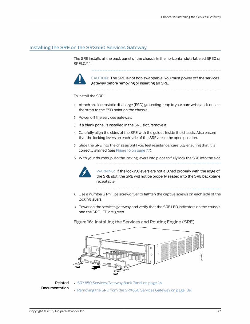
Installing the SRE on the SRX650 Services Gateway
The SRE installs at the back panel of the chassis in the horizontal slots labeled SRE0 or
SRE1.0/1.1.
CAUTION: The SRE is not hot-swappable. Youmust power off the servicesgateway before removing or inserting an SRE.
To install the SRE:
1. Attach an electrostatic discharge (ESD) grounding strap to your bare wrist, and connect
the strap to the ESD point on the chassis.
2. Power off the services gateway.
3. If a blank panel is installed in the SRE slot, remove it.
4. Carefully align the sides of the SRE with the guides inside the chassis. Also ensure
that the locking levers on each side of the SRE are in the open position.
5. Slide the SRE into the chassis until you feel resistance, carefully ensuring that it is
correctly aligned (see Figure 16 on page 77).
6. With your thumbs, push the locking levers into place to fully lock the SRE into the slot.
WARNING: If the locking levers are not aligned properly with the edge ofthe SRE slot, the SREwill not be properly seated into the SRE backplanereceptacle.
7. Use a number 2 Phillips screwdriver to tighten the captive screws on each side of the
locking levers.
8. Power on the services gateway and verify that the SRE LED indicators on the chassis
and the SRE LED are green.
Figure 16: Installing the Services and Routing Engine (SRE)
g032
707
RelatedDocumentation
SRX650 Services Gateway Back Panel on page 24•
• Removing the SRE from the SRX650 Services Gateway on page 139
77Copyright © 2016, Juniper Networks, Inc.
Chapter 15: Installing the Services Gateway

• SRX650 Services Gateway Services and Routing Engine 6 on page 11
• Powering On the SRX650 Services Gateway on page 92
Installing an AC Power Supply on the SRX650 Services Gateway
To install an AC power supply:
1. Attach an electrostatic discharge (ESD) grounding strap to your bare wrist and connect
the strap to one of the ESD points on the chassis. For more information about ESD,
see “Preventing Electrostatic Discharge Damage to the SRX650 Services Gateway”
on page 164.
2. Using both hands, slide the power supply straight into the chassis until the power
supply is fully seated in the chassis slot. The power supply faceplate should be flush
with any adjacent power supply faceplate (see Figure 17 on page 78).
3. Attach the power cord to the power supply.
4. Route the power cord along the cable restraint toward the left or right corner of the
chassis. If they are needed to hold the power cord in place, thread plastic cable ties,
which you must provide, through the openings on the cable restraint.
5. Attach the power cord to the AC power source, and switch on the dedicated facility
circuit breaker for the power supply. Follow the ESD and connection instructions for
your site. If the power supply is correctly installed and functioning normally, the POWER
LED lights steadily.
Figure 17: InstallinganACPowerSupplyontheSRX650ServicesGatewayg0
3271
0
RelatedDocumentation
Removing an AC Power Supply from the SRX650 Services Gateway on page 141•
• Connecting an AC Power Cord to the SRX650 Services Gateway on page 90
• Required Tools and Parts for Replacing Hardware Components on the SRX650 Services
Gateway on page 137
Copyright © 2016, Juniper Networks, Inc.78
SRX650 Services Gateway Hardware Guide
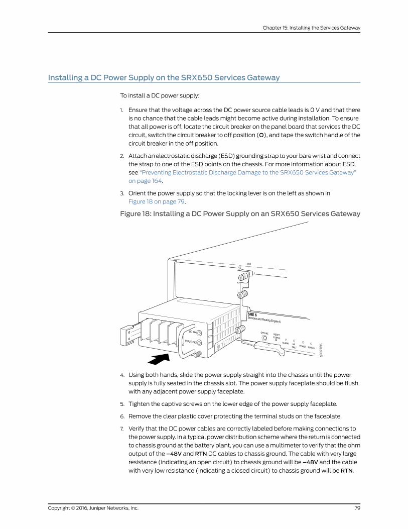
Installing a DC Power Supply on the SRX650 Services Gateway
To install a DC power supply:
1. Ensure that the voltage across the DC power source cable leads is 0 V and that there
is no chance that the cable leads might become active during installation. To ensure
that all power is off, locate the circuit breaker on the panel board that services the DC
circuit, switch the circuit breaker to off position (O), and tape the switch handle of the
circuit breaker in the off position.
2. Attach an electrostatic discharge (ESD) grounding strap to your bare wrist and connect
the strap to one of the ESD points on the chassis. For more information about ESD,
see “Preventing Electrostatic Discharge Damage to the SRX650 Services Gateway”
on page 164.
3. Orient the power supply so that the locking lever is on the left as shown in
Figure 18 on page 79.
Figure 18: Installing a DCPower Supply on an SRX650Services Gateway
4. Using both hands, slide the power supply straight into the chassis until the power
supply is fully seated in the chassis slot. The power supply faceplate should be flush
with any adjacent power supply faceplate.
5. Tighten the captive screws on the lower edge of the power supply faceplate.
6. Remove the clear plastic cover protecting the terminal studs on the faceplate.
7. Verify that the DC power cables are correctly labeled before making connections to
the power supply. In a typical power distribution scheme where the return is connected
to chassis ground at the battery plant, you can use a multimeter to verify that the ohm
output of the –48V and RTN DC cables to chassis ground. The cable with very large
resistance (indicating an open circuit) to chassis ground will be –48V and the cable
with very low resistance (indicating a closed circuit) to chassis ground will be RTN.
79Copyright © 2016, Juniper Networks, Inc.
Chapter 15: Installing the Services Gateway
CAUTION: Youmust ensure that power connectionsmaintain the properpolarity. Thepower source cablesmight be labeled (+)and (–) to indicatetheir polarity. There is no standard color coding for DC power cables. Thecolor coding usedby the externalDCpower source at your site determinesthe color coding for the leads on the power cables that attach to theterminal studs on each power supply.
8. Using a number 2 Phillips screwdriver, remove the screws and square washers from
the terminal studs.
9. Secure each power cable lug to the terminal studs, first with the square washer, then
with the screw. Apply between 23 lb-in. (2.6 Nm) and 25 lb-in. (2.8 Nm) of torque to
each screw.
a. Attach the positive (+) DC source power cable lug to the RTN (return) terminal.
b. Attach the negative (–) DC source power cable lug to the –48V (input) terminal.
10. Replace the clear plastic cover over the terminal studs on the faceplate.
11. Verify that the power cables are connected correctly, that they are not touching or
blocking access to services gateway components, and that they do not drape where
people could trip on them.
12. Remove the tape from the switch handle of the circuit breaker on the panel board
that services the DC circuit and switch the circuit breaker to the on position ( | ).
Observe the status LEDs on the power supply faceplate. If the power supply is correctly
installed and functioning normally, the POWER LED lights green steadily on the services
gateway front panel.
NOTE: If more than one power supply is being installed, turn on all powersupplies at the same time.
RelatedDocumentation
• Required Tools and Parts for Replacing Hardware Components on the SRX650 Services
Gateway on page 137
• Removing a DC Power Supply on the SRX650 Services Gateway on page 143
• Removing a DC Power Supply Cable from the SRX650 Services Gateway on page 144
Copyright © 2016, Juniper Networks, Inc.80
SRX650 Services Gateway Hardware Guide
CHAPTER 16
Grounding theSRX650ServicesGateway
• Required Tools and Parts for Grounding, Powering On, and Powering Off the SRX650
Services Gateway on page 81
• SRX650 Services Gateway Grounding Specifications on page 81
• Grounding the SRX650 Services Gateway on page 82
Required Tools and Parts for Grounding, Powering On, and Powering Off the SRX650Services Gateway
To ground and to provide power to the services gateway, you need Phillips (+)
screwdrivers, numbers 1 and 2.
RelatedDocumentation
Grounding the SRX650 Services Gateway on page 82•
• Powering On the SRX650 Services Gateway on page 92
• Powering Off the SRX650 Services Gateway on page 93
• Organizing Interface Cables on the SRX650 Services Gateway on page 85
• SRX650 Services Gateway General Safety Guidelines and Warnings on page 161
SRX650 Services Gateway Grounding Specifications
To meet safety and electromagnetic interference (EMI) requirements and to ensure
proper operation, the SRX650 Services Gateway must be adequately grounded before
power is connected. You must provide a grounding lug to connect the services gateway
to earth ground.
WARNING: Before servicesgateway installationbegins, a licensedelectricianmust attach a cable lug to the grounding and power cables that you supply.A cable with an incorrectly attached lug can damage the services gateway(for example, by causing a short circuit).
To ground the services gateway before connecting power, you connect the grounding
cable to earth ground and then attach the lug on the cable to the chassis grounding point,
using the screw.
81Copyright © 2016, Juniper Networks, Inc.

Table 23 on page 82 lists the specifications of the grounding cable used with the device.
Table 23: Grounding Cable Specifications for the SRX650 ServicesGateway
SpecificationGrounding Requirement
14 AWG single-strand wire cableGrounding cable
Up to 25AAmperage of grounding cable
Ring-type, vinyl-insulated TV14-6R lug, orequivalent
Grounding lug
RelatedDocumentation
Grounding the SRX650 Services Gateway on page 82•
• Connecting the SRX650 Services Gateway to the AC Power Supply on page 89
• Powering On the SRX650 Services Gateway on page 92
• Powering Off the SRX650 Services Gateway on page 93
Grounding the SRX650 Services Gateway
You ground the services gateway by connecting a grounding cable to earth ground and
then attaching it to the chassis grounding points located on the right side of the device
(if you are facing the front of the chassis) using two metric M5 x 0.8, 12 mm long grounding
screws.
You must provide the following items:
• Two metric M5 x 0.8, 12 mm long grounding screws
• Grounding cables
• Cable lugs (for example, Panduit LCC6-10A-L)
CAUTION: Before services gateway installationbegins, a licensedelectricianmust attach a cable lug to the grounding and power cables that you supply.A cable with an incorrectly attached lug can damage the services gateway(for example, by causing a short circuit).
To ground the services gateway:
1. Attach an electrostatic discharge (ESD) grounding strap to your bare wrist, and connect
the strap to the ESD point on the chassis. For more details, see “Preventing Electrostatic
Discharge Damage to the SRX650 Services Gateway” on page 164.
2. Ensure that all grounding surfaces are clean and brought to a bright finish before
grounding connections are made.
3. Connect the grounding cable to a proper earth ground.
Copyright © 2016, Juniper Networks, Inc.82
SRX650 Services Gateway Hardware Guide

4. Place the grounding cable lugs over the grounding points (sized for metric M5 x 0.8,
12 mm long grounding screws) on the side of the chassis.
5. Secure the grounding cable lugs to the grounding points, first with the washers, then
with the screws.
6. Dress the grounding cable and verify that it does not touch or block access to the
services gateway components and that it does not drape where people could trip on
it.
RelatedDocumentation
• Powering On the SRX650 Services Gateway on page 92
• Powering Off the SRX650 Services Gateway on page 93
• Required Tools and Parts for Grounding, Powering On, and Powering Off the SRX650
Services Gateway on page 81
• SRX650 Services Gateway General Safety Guidelines and Warnings on page 161
83Copyright © 2016, Juniper Networks, Inc.
Chapter 16: Grounding the SRX650 Services Gateway

Copyright © 2016, Juniper Networks, Inc.84
SRX650 Services Gateway Hardware Guide
CHAPTER 17
Connecting the SRX650 ServicesGateway to External Devices
• Required Tools and Parts for Connecting the SRX650 Services Gateway on page 85
• Organizing Interface Cables on the SRX650 Services Gateway on page 85
• Connecting the Modem to the Console Port on the SRX650 Services
Gateway on page 86
• Connecting the CLI at the User End for the SRX650 Services Gateway on page 86
• Connecting the Modem at the SRX650 Services Gateway End on page 87
Required Tools and Parts for Connecting the SRX650 Services Gateway
To connect the services gateway, you need an electrostatic discharge (ESD) grounding
wrist strap.
RelatedDocumentation
Connecting the SRX650 Services Gateway to the AC Power Supply on page 89•
• Connecting the SRX650 Services Gateway to the DC Power Supply on page 91
• Organizing Interface Cables on the SRX650 Services Gateway on page 85
Organizing Interface Cables on the SRX650 Services Gateway
Arrange network cables as follows to prevent them from dislodging or developing stress
points:
• Secure cables so that they are not supporting their own weight as they hang to the
floor.
• Place excess cable out of the way in neatly coiled loops.
• Use fasteners to maintain the shape of cable loops.
RelatedDocumentation
Connecting the SRX650 Services Gateway to the AC Power Supply on page 89•
• Connecting the SRX650 Services Gateway to the DC Power Supply on page 91
• Preventing Electrostatic Discharge Damage to the SRX650 Services Gateway on
page 164
85Copyright © 2016, Juniper Networks, Inc.
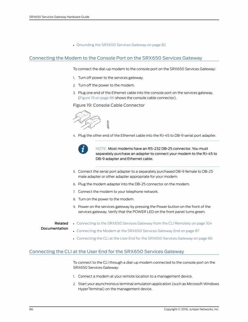
• Grounding the SRX650 Services Gateway on page 82
Connecting theModem to the Console Port on the SRX650 Services Gateway
To connect the dial-up modem to the console port on the SRX650 Services Gateway:
1. Turn off power to the services gateway.
2. Turn off the power to the modem.
3. Plug one end of the Ethernet cable into the console port on the services gateway.
(Figure 19 on page 86 shows the console cable connector).
Figure 19: Console Cable Connector
4. Plug the other end of the Ethernet cable into the RJ-45 to DB-9 serial port adapter.
NOTE: Mostmodems have an RS-232 DB-25 connector. Youmustseparately purchase an adapter to connect your modem to the RJ-45 toDB-9 adapter and Ethernet cable.
5. Connect the serial port adapter to a separately purchased DB-9 female to DB-25
male adapter or other adapter appropriate for your modem.
6. Plug the modem adapter into the DB-25 connector on the modem.
7. Connect the modem to your telephone network.
8. Turn on the power to the modem.
9. Power on the services gateway by pressing the Power button on the front of the
services gateway. Verify that the POWER LED on the front panel turns green.
RelatedDocumentation
Connecting to the SRX650 Services Gateway from the CLI Remotely on page 104•
• Connecting the Modem at the SRX650 Services Gateway End on page 87
• Connecting the CLI at the User End for the SRX650 Services Gateway on page 86
Connecting the CLI at the User End for the SRX650 Services Gateway
To connect to the CLI through a dial-up modem connected to the console port on the
SRX650 Services Gateway:
1. Connect a modem at your remote location to a management device.
2. Start your asynchronous terminal emulation application (such as Microsoft Windows
HyperTerminal) on the management device.
Copyright © 2016, Juniper Networks, Inc.86
SRX650 Services Gateway Hardware Guide

3. Select the COM port to which the modem is connected (for example, COM1).
4. Configure the port settings shown in Table 24 on page 87.
Table 24: Port Settings
ValuePort Settings
9600Bits per second
8Data bits
NoneParity
1Stop bits
NoneFlow control
5. In the HyperTerminal window, type AT.
For more information on the AT commands, see the Initial Configuration for Security
Devices.
An OK response indicates that the modem can communicate successfully with the
COM port on the management device.
6. To dial the modem that is connected to the console port on the services gateway,
type ATDT remote-modem-number. For example, if the phone number of the modem
connected to the console port on the services gateway is 0019785551234, type ATDT
0019785551234.
The services gateway login prompt appears.
7. Log in as the user root. No password is required at initial connection, but you must
assign a root password before you commit any configuration settings.
RelatedDocumentation
Connecting to the SRX650 Services Gateway from the CLI Remotely on page 104•
• Connecting the Modem at the SRX650 Services Gateway End on page 87
• Connecting the Modem to the Console Port on the SRX650 Services Gateway on
page 86
Connecting theModem at the SRX650 Services Gateway End
Before you can connect a dial-up modem to the console port on the SRX650 Services
Gateway, you must configure the modem to accept a call on the first ring and to accept
DTR signals. You must also disable flow control on the modem.
NOTE: These instructions use Hayes-compatible modem commands toconfigure themodem. If your modem is not Hayes-compatible, refer to thedocumentation for your modem and enter equivalent modem commands.
87Copyright © 2016, Juniper Networks, Inc.
Chapter 17: Connecting the SRX650 Services Gateway to External Devices
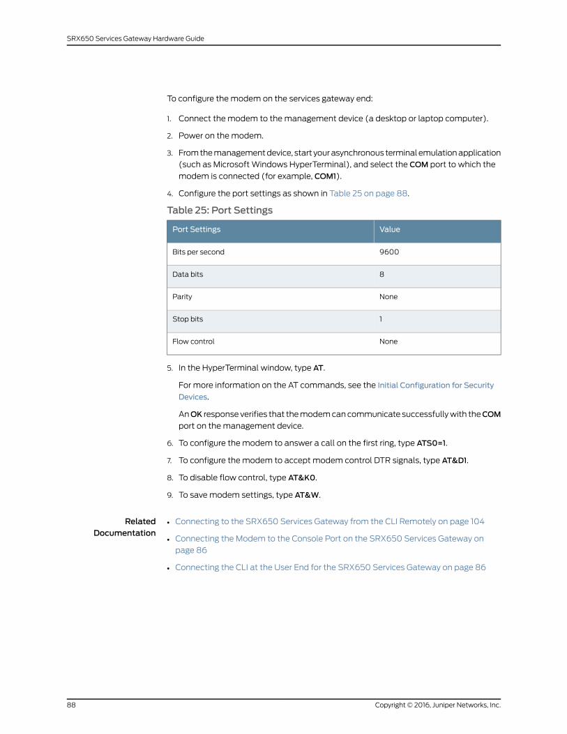
To configure the modem on the services gateway end:
1. Connect the modem to the management device (a desktop or laptop computer).
2. Power on the modem.
3. From the management device, start your asynchronous terminal emulation application
(such as Microsoft Windows HyperTerminal), and select the COM port to which the
modem is connected (for example, COM1).
4. Configure the port settings as shown in Table 25 on page 88.
Table 25: Port Settings
ValuePort Settings
9600Bits per second
8Data bits
NoneParity
1Stop bits
NoneFlow control
5. In the HyperTerminal window, type AT.
For more information on the AT commands, see the Initial Configuration for Security
Devices.
AnOK response verifies that the modem can communicate successfully with theCOM
port on the management device.
6. To configure the modem to answer a call on the first ring, type ATS0=1.
7. To configure the modem to accept modem control DTR signals, type AT&D1.
8. To disable flow control, type AT&K0.
9. To save modem settings, type AT&W.
RelatedDocumentation
• Connecting to the SRX650 Services Gateway from the CLI Remotely on page 104
• Connecting the Modem to the Console Port on the SRX650 Services Gateway on
page 86
• Connecting the CLI at the User End for the SRX650 Services Gateway on page 86
Copyright © 2016, Juniper Networks, Inc.88
SRX650 Services Gateway Hardware Guide

CHAPTER 18
Providing Power to the SRX650 ServicesGateway
• Connecting the SRX650 Services Gateway to the AC Power Supply on page 89
• Connecting an AC Power Cord to the SRX650 Services Gateway on page 90
• Connecting the SRX650 Services Gateway to the DC Power Supply on page 91
• Powering On the SRX650 Services Gateway on page 92
• Powering Off the SRX650 Services Gateway on page 93
Connecting the SRX650 Services Gateway to the AC Power Supply
CAUTION: Do notmix AC and DC power supplies within the same servicesgateway. Damage to the devicemight occur.
The 645 W AC power supply with PoE support is available for the SRX650 Services
Gateway. You connect AC power to the services gateway by attaching the power cord
from the AC power source to the AC appliance inlet located on the power supply. The
power cord is not provided.
To connect the services gateway to an AC power supply:
1. Attach an electrostatic discharge (ESD) grounding strap to your bare wrist, and connect
the strap to the ESD point on the side of the chassis.
2. Locate the power cord or cords you will use to connect the services gateway to AC
power.
3. Insert the appliance coupler end of the power cord into the appliance inlet on the
power supply.
4. Insert the power cord plug into an external AC power source receptacle.
89Copyright © 2016, Juniper Networks, Inc.

NOTE: Each power supply must be connected to a dedicated AC powerfeed and a dedicated external circuit breaker. We recommend that youuse a 15 A (250 VAC)minimum, or as permitted by local code.
5. Dress the power cord appropriately. Verify that the power cord does not block the air
exhaust and access to services gateway components or drape where people could
trip on it.
NOTE: The services gatewaymust be connected to earth ground duringnormal operation. The protective earthing terminal on the side of the chassisis provided to connect the services gateway to ground.
CAUTION: Werecommendusinga surgeprotector for thepower connection.
RelatedDocumentation
Preventing Electrostatic Discharge Damage to the SRX650 Services Gateway on
page 164
•
• Grounding the SRX650 Services Gateway on page 82
• Organizing Interface Cables on the SRX650 Services Gateway on page 85
• SRX650 Services Gateway General Safety Guidelines and Warnings on page 161
Connecting an AC Power Cord to the SRX650 Services Gateway
To connect the AC power cord:
1. Locate a replacement power cord with the type of plug appropriate for your
geographical location.
2. Connect the power cord to the power supply.
3. Insert the power cord plug into an external AC power source receptacle.
4. Route the power cord along the cable restraint toward the left or right corner of the
chassis. If they are needed to hold the power cord in place, thread plastic cable ties,
which you must provide, through the openings on the cable restraint.
5. Verify that the power cord does not block the air exhaust and access to services
gateway components, or drape where people could trip on it. If the power supply is
correctly installed and functioning normally, the POWER LED lights steadily.
RelatedDocumentation
Disconnecting an AC Power Cord from the SRX650 Services Gateway on page 142•
• Removing an AC Power Supply from the SRX650 Services Gateway on page 141
• Required Tools and Parts for Replacing Hardware Components on the SRX650 Services
Gateway on page 137
Copyright © 2016, Juniper Networks, Inc.90
SRX650 Services Gateway Hardware Guide

Connecting the SRX650 Services Gateway to the DC Power Supply
CAUTION: Do notmix AC and DC power supplies within the same servicesgateway. Damage to the devicemight occur.
The 645 W DC power supply with PoE support is available for the SRX650 Services
Gateway.
WARNING: Before performing the following procedure, ensure that power isremoved from theDC circuit. To ensure that all power is off, locate the circuitbreaker on the panel board that services the DC circuit, switch the circuitbreaker to the off position (O), and tape the switch handle of the circuit
breaker in the off position.
You connect DC power to the device by attaching power cables from the external DC
power sources to the terminal studs on the power supply faceplate. You must provide
the power cables (the cable lugs are supplied with the services gateway).
To connect the DC source power cables to the services gateway power supply:
1. Switch off the dedicated facility circuit breakers. Ensure that the voltage across the
DC power source cable leads is 0 V and that there is no chance that the cable leads
might become active during installation.
2. Attach an electrostatic discharge (ESD) grounding strap to your bare wrist, and connect
the strap to the ESD point on the side of the chassis.
3. Remove the clear plastic cover protecting the terminal studs on the faceplate.
4. Verify that the DC power cables are correctly labeled before making connections to
the power supply. In a typical power distribution scheme where the return is connected
to chassis ground at the battery plant, you can use a multimeter to verify that the ohm
output of the –48V and RTN DC cables to chassis ground. The cable with very large
resistance (indicating an open circuit) to chassis ground will be –48V and the cable
with very low resistance (indicating a closed circuit) to chassis ground will be RTN.
CAUTION: Youmust ensure that power connectionsmaintain the properpolarity. The power source cablesmight be labeled (+)and (–) to indicate
their polarity. There is no standard color coding for DC power cables. Thecolor coding usedby the externalDCpower source at your site determinesthe color coding for the leads on the power cables that attach to theterminal studs on the power supply.
5. Remove the screws and square washers from the terminals. Use a number 2 Phillips
screwdriver.
91Copyright © 2016, Juniper Networks, Inc.
Chapter 18: Providing Power to the SRX650 Services Gateway
6. Secure each power cable lug to the terminals, first with the square washer, then with
the screw. Apply between 23 lb-in. (2.6 Nm) and 25 lb-in. (2.8 Nm) of torque to each
screw.
• Secure each positive (+) DC source power cable lug to a RTN (return) terminal.
• Secure each negative (–) DC source power cable lug to a –48V (input) terminal.
7. Replace the clear plastic cover over the terminal studs on the faceplate.
8. Verify that the power cables are connected correctly, that they are not touching or
blocking access to services gateway components, and that they do not drape where
people could trip on them.
NOTE: The services gatewaymust be connected to earth ground duringnormal operation. The protective earthing terminal on the side of the chassisis provided to connect the services gateway to ground.
CAUTION: Werecommendusinga surgeprotector for thepower connection.
RelatedDocumentation
Preventing Electrostatic Discharge Damage to the SRX650 Services Gateway on
page 164
•
• Grounding the SRX650 Services Gateway on page 82
• Organizing Interface Cables on the SRX650 Services Gateway on page 85
• SRX650 Services Gateway General Safety Guidelines and Warnings on page 161
Powering On the SRX650 Services Gateway
To power on the services gateway:
1. Ensure that you have connected the power supply to the device.
2. Insert the plug of the power supply adapter into an AC or DC power source receptacle.
a. Using AC Power supply—Insert the appliance coupler end of the power cord into
the appliance inlet on the power supply and the power cord plug into an external
AC power source receptacle.
b. Using DC power supply—Connect DC power cables to theA+ andA- terminals and
the other ends to an external DC power source. If you have two DC power sources
and wish to deploy A/B feed redundancy for the services gateway, also connect
DC power cables to the B+ and B- terminals and the other ends to an external DC
power source.
CAUTION: Youmust ensure that power connectionsmaintain theproper polarity. The power source cablesmight be labeled (+) and (–)
Copyright © 2016, Juniper Networks, Inc.92
SRX650 Services Gateway Hardware Guide

to indicate theirpolarity.There isnostandardcolorcoding forDCpowercables. The color coding used by the external DC power source at yoursite determines the color coding for the leads on the power cables thatattach to the terminals on the power supply.
3. Turn on the power to the AC or DC power receptacle.
The device starts automatically as the power supply completes its startup sequence.
The POWER LED (on the front panel of the chassis) lights during startup and remains
on steadily when the services gateway is operating normally.
RelatedDocumentation
Grounding the SRX650 Services Gateway on page 82•
• Resetting the SRX650 Services Gateway on page 133
• Powering Off the SRX650 Services Gateway on page 93
• SRX650 Services Gateway Front Panel on page 18
Powering Off the SRX650 Services Gateway
To power off the services gateway, keep the Power button on the front of the services
gateway pressed for 4 seconds. The services gateway begins gracefully shutting down
the operating system, the Services and Routing Engine (SRE) and any Gigabit-Backplane
Physical Interface Modules (GPIMs), and then powers itself off.
NOTE: Forced shutdown is not supported on theSRX650ServicesGateway.
To remove power completely from the services gateway, unplug the AC power cord or
DC power supply cable.
After powering off a power supply, wait at least 60 seconds before turning it back on.
After powering on a power supply, wait at least 10 seconds before turning it off.
If the system is completely powered off when you turn on the power supply, the services
gateway starts as the power supply completes its startup sequence. If the services
gateway finishes starting and you need to power off the system again, first issue the
request system halt CLI command.
After a power supply is turned on, it can take up to 60 seconds for status indicators—such
as the POWER LED (on the front panel of the chassis) and the show chassis command
display—to indicate that the power supply is functioning normally. Ignore error indicators
that appear during the first 60 seconds.
RelatedDocumentation
• Grounding the SRX650 Services Gateway on page 82
• Powering On the SRX650 Services Gateway on page 92
• Resetting the SRX650 Services Gateway on page 133
93Copyright © 2016, Juniper Networks, Inc.
Chapter 18: Providing Power to the SRX650 Services Gateway
• SRX650 Services Gateway Front Panel on page 18
Copyright © 2016, Juniper Networks, Inc.94
SRX650 Services Gateway Hardware Guide

CHAPTER 19
Performing Initial Configuration
• SRX650 Services Gateway Software Configuration Overview on page 95
• SRX650 Services Gateway Basic Settings on page 96
• Connecting to the SRX650 Services Gateway Setup Wizard on page 98
• SRX650 Services Gateway Secure Web Access Overview on page 100
• SRX650 Services Gateway Secure CLI Access Overview on page 101
• Connecting to the SRX650 Services Gateway from the CLI Locally on page 102
• Connecting to the SRX650 Services Gateway from the CLI Remotely on page 104
• Viewing Factory-Default Settings of the SRX650 Services Gateway on page 105
• Configuring Basic Settings for the SRX650 Services Gateway with the CLI or the J-Web
Interface on page 111
• Displaying Basic Connectivity Configurations for the SRX650 Services
Gateway on page 115
• Built-In Ethernet Ports for the SRX650 Services Gateway on page 116
SRX650 Services Gateway Software Configuration Overview
The Juniper Networks Junos operating system (Junos OS) is preinstalled on the SRX650
Services Gateway. When the services gateway is powered on, it is ready to be configured.
If you are setting up a services gateway for the first time, you can use the J-Web setup
wizard or the command-line interface (CLI) to perform the initial configuration.
If you are setting up many services gateways, autoinstallation can help automate the
configuration process. See “SRX650 Services Gateway Autoinstallation Overview” on
page 66.
Before you configure the services gateway for the first time, you should complete the
prerequisite tasks listed in Table 26 on page 96.
95Copyright © 2016, Juniper Networks, Inc.

Table 26: Services Gateway Prerequisite Tasks
DetailsTask
• Device identification
• Hostname for the device on the network
• Domain to which the device belongs onthe network
• Password for the root user
• Time zone information
• System time and zone for servicesgateway location
• IP address of a Network Time Protocol(NTP) server, if NTP is used to set the timeon the services gateway
• Network settings for the services gateway:
IP address of a DNS server
• List of domains that can be appended tohostnames for DNS resolution
Gather information on:
• Management device, such as a desktop orlaptop computer, with an Ethernet port
• Ethernet cable
If you are performing the initial configurationwith the J-Web setup wizard, gather thefollowing equipment:
• Management device, such as a desktop orlaptop computer, with a serial port and anasynchronous terminal application (such asMicrosoft Windows HyperTerminal)
• Serial cable
• For a remote connection, gather the followingequipment:
• Two dial-up modems
• An adapter appropriate for your modem;for example, DB-25 male or similar
If you are performing the initial configurationwith the CLI, gather the following equipment:
RelatedDocumentation
SRX650 Services Gateway Basic Settings on page 96•
• Connecting to the SRX650 Services Gateway Setup Wizard on page 98
• Connecting to the SRX650 Services Gateway from the CLI Locally on page 102
• Connecting to the SRX650 Services Gateway from the CLI Remotely on page 104
SRX650 Services Gateway Basic Settings
Table 27 on page 97 provides information on basic connectivity settings.
Copyright © 2016, Juniper Networks, Inc.96
SRX650 Services Gateway Hardware Guide

Table 27: Services Gateway Basic Connectivity Settings Details
SettingsDescriptionElement
The hostname refers to the specific machine, whilethe domain name is shared among all devices in agiven network. Together the hostname and domainname identify the device in the network.
The hostname defines the network or subnetwork towhich your services gateway belongs.
Deviceidentification
The root password must meet the following criteria:
• Must be at least six characters long
• Can include most character classes (alphabetic,numeric, and special characters), except controlcharacters
• Must contain at least one change of case orcharacter class
NOTE: For Common Criteria environments only, thepassword must be between 10 and 20 characters longand must include at least 3 of the 5 character classes(uppercase letters, lowercase letters, punctuationmarks, numbers, and other special characters).Control characters are not recommended. For moreinformation, see theConfigurationGuides for JunosOS Public Sector Certifications.
Initially, the root password is not defined on the device.To ensure basic security, you must define the rootpassword during initial configuration. If a root passwordis not defined, you cannot commit configurationsettings on the device.
NOTE: The root password is mandatory.
NOTE: If you use a plaintext password, the devicedisplays the password as an encrypted string so thatusers viewing the configuration cannot see it.
Rootpassword
If you plan to include your device in several domains,add these domains to the configuration so that theyare included in a DNS search. When DNS searchesare requested, the domain suffixes are appended tothe hostnames.
A Domain Name System (DNS) server on the networkmaintains a database for resolving hostnames and IPaddresses. Network devices can query the DNS serverby hostnames rather than IP addresses. The servicesgateway accesses the DNS servers that are added tothe configuration to resolve hostnames in the order inwhich you list them.
Networksettings
The default gateway entry is always present in therouting and forwarding tables.
A default gateway is a static route that is used to directpackets addressed to networks not explicitly listed inthe routing table. If a packet arrives at the servicesgateway with an address for which the device does nothave routing information, the services gateway sendsthe packet to the default gateway.
Defaultgateway
A Network Time Protocol (NTP) server providesaccurate time across a network. The devicesynchronizes the system time with the NTP serverand periodically accesses the NTP server to maintainthe correct time.
The time zone and system time must be accurate sothat the device schedules events and operations asexpected.
NOTE: For Common Criteria compliance, you mustconfigure NTP to provide accurate timestamps forsystem log messages. For more information, see theConfiguration Guides for Junos OS Public SectorCertifications
You define the time zone for the location where youplan to operate the services gateway by using adesignation that consists of the following informationfor the location:
• Name of the continent or ocean—for example,America or Pacific
• Name of the major city or other geographic featurein the time zone—for example, Boston or Azores
Time zoneand systemtime
97Copyright © 2016, Juniper Networks, Inc.
Chapter 19: Performing Initial Configuration

Table 27: Services Gateway Basic Connectivity Settings Details (continued)
SettingsDescriptionElement
NOTE: The backup device must be located on thesame subnet as the primary device.
To configure a backup device, you must use the CLI.You cannot configure a backup device using J-Web.
NOTE: This feature will be supported in a futurerelease.
You can specify a backup device to take over when therouting protocol process of the services gateway is notrunning:
• When the services gateway is starting.
• When its routing protocol process has failed. In thissituation, packets arriving at a services gateway arerouted to the backup device. When the routingprotocol process starts up again, the address of thebackup device is removed from the routing andforwarding tables of the services gateway.
Backupdevice
RelatedDocumentation
SRX650 Services Gateway Software Configuration Overview on page 95•
• Connecting to the SRX650 Services Gateway Setup Wizard on page 98
• Connecting to the SRX650 Services Gateway from the CLI Locally on page 102
• Connecting to the SRX650 Services Gateway from the CLI Remotely on page 104
Connecting to the SRX650 Services Gateway SetupWizard
If you plan to use the setup wizard to configure the SRX650 Services Gateway, you must
connect through the built-in Ethernet port 0/1 as shown in Figure 20 on page 99.
NOTE: To access the J-Web interface, your management device requires asupported browser: either Microsoft Internet Explorer version 7.0 or MozillaFirefox version 3.0 (or later).
Copyright © 2016, Juniper Networks, Inc.98
SRX650 Services Gateway Hardware Guide

Figure 20: Connecting to the Ethernet Port on the SRX650 ServicesGateway
g032
718
Ethernet cable
Ethernet port
SRX650
To enable communication between the management device and the services gateway,
port 0/1 is preconfigured with the IP address 192.168.1.1 and uses DHCP to assign an IP
address in the 192.168.1.0/24 network to any connected device.
To connect a management device to built-in Ethernet port 0/1:
1. Ensure that the IP address for the Ethernet port on the management device is
configured in one of the following ways:
• The IP address is assigned by DHCP.
• The IP address is on the 192.168.1.0/24 subnetwork (but is not 192.168.1.1).
2. Turn off the power to the management device.
3. Plug one end of the Ethernet cable (Figure 21 on page 99 shows the connector) into
the Ethernet port on the management device.
Figure 21: Ethernet Cable Connector (RJ-45)
4. Connect the other end of the Ethernet cable to built-in Ethernet port 0/1 on the services
gateway.
5. Power on the services gateway by connecting the power cord or by pressing the Power
button on the front of the services gateway.
6. Wait until the STATUS LED on the front panel turns solid green.
99Copyright © 2016, Juniper Networks, Inc.
Chapter 19: Performing Initial Configuration
7. Turn on the power to the management device. The services gateway assigns an IP
address to the management device within the 192.168.1.0/24 subnetwork if the
management device is configured to use DHCP.
8. To access the setup wizard, open a Web browser on the management device and
enter the IP address 192.168.1.1 in the address field.
9. Specify the default username as root. Do not enter any value in the Password field.
10. Press Enter. The J-Web setup wizard appears.
NOTE: The upper left area of the wizard page showswhere you are in thesetupprocess.Clicka field in thewizardpage todisplay informationaboutthat field in the lower left area of the page.
11. Use the wizard to configure basic settings such as Hostname, Domain Name, and
Root Password for your services gateway. You may also use the wizard to configure
a default gateway, DNS servers, domain search, VLANs, interfaces, and J-Web
preferences. For details on using the J-Web setup wizard to configure basic settings
for the services gateway, see “Configuring Basic Settings for the SRX650 Services
Gateway with the CLI or the J-Web Interface” on page 111.
12. Click Commit to apply the configuration. After configuring the basic settings, you are
prompted to log out. Relaunch the page to see the settings and continue working in
J-Web.
NOTE: Youmust manually configure the IP address for themanagementport that you are using before you save your initial configuration. Whenyou save the configuration for the first time, you will lose the connectionto theservicesgateway if youhavenotmanually configured the IPaddress.If you lose the connection through themanagement interface, youmustconnect through the console port.
RelatedDocumentation
Performing Initial Software Configuration on the SRX650 Services Gateway Using the
SetupWizard
•
• Connecting to the SRX650 Services Gateway from the CLI Locally on page 102
• Connecting to the SRX650 Services Gateway from the CLI Remotely on page 104
SRX650 Services Gateway SecureWeb Access Overview
You can manage a services gateway remotely through the J-Web interface. To
communicate with the services gateway, the J-Web interface uses Hypertext Transfer
Protocol (HTTP). HTTP allows easy Web access but does not include encryption. The
data transmitted between the client and the services gateway by means of HTTP is
vulnerable to interception and attack. To enable secure Web access, a services gateway
Copyright © 2016, Juniper Networks, Inc.100
SRX650 Services Gateway Hardware Guide
supports HTTP over Secure Sockets Layer (HTTPS). You can enable HTTP or HTTPS
access on specific interfaces and ports as needed.
The services gateway uses the SSL protocol to provide secure management of services
gateways through the J-Web interface. SSL uses public-private key technology, which
requires a paired private key and an authentication certificate to provide the SSL service.
SSL encrypts communication between your device and the Web browser with a session
key negotiated by the SSL server certificate.
An SSL certificate includes identifying information such as a public key and a signature
made by a certificate authority (CA). When you access the services gateway through
HTTPS, an SSL handshake authenticates the server and the client and begins a secure
session. If the information does not match or if the certificate has expired, your access
to the services gateway through HTTPS is restricted.
Without SSL encryption, communication between your services gateway and the browser
is sent in the open and can be intercepted. We recommend that you enable HTTPS access
on your WAN interfaces.
On services gateways, HTTP access is enabled by default on the built-in management
interfaces. By default, HTTPS access is supported on any interface with an SSL server
certificate.
You can use the J-Web interface or the CLI to configure secure Web access.
Before you configure secure Web access for the first time, you must complete the following
tasks:
• Establish basic connectivity.
• Obtain an SSL certificate from a trusted signing authority.
For more details about configuring secure web access on your services gateway, see the
Initial Configuration for Security Devices.
RelatedDocumentation
SRX650 Services Gateway Software Configuration Overview on page 95•
• Performing Initial Software Configuration on the SRX650 Services Gateway Using the
SetupWizard
• Configuring Basic Settings for the SRX650 Services Gateway with the CLI or the J-Web
Interface on page 111
SRX650 Services Gateway Secure CLI Access Overview
Telnet allows you to connect to the SRX650 Services Gateway and access the CLI to
execute commands from a remote system. Telnet connections are not encrypted and
therefore can be intercepted.
NOTE: Telnet access to the root account is prohibited. Youmust usemoresecuremethods, such as SSH, to log in as root.
101Copyright © 2016, Juniper Networks, Inc.
Chapter 19: Performing Initial Configuration
SSH provides the following features:
• Allows you to connect to the services gateway and to access the CLI to execute
commands from a remote system
• Unlike Telnet, encrypts traffic so that it cannot be intercepted
• Can be configured so that connections are authenticated by a digital certificate
• Uses public–private key technology for both connection and authentication
The SSH client software must be installed on the machine where the client application
runs. If the SSH private key is encrypted (for greater security), the SSH client must be
able to access the passphrase used to decrypt the key.
For information about obtaining SSH software, see http://www.ssh.com and
http://www.openssh.com.
If you are using a Junos XML protocol server to configure and monitor devices, you can
activate cleartext access on the services gateway to allow unencrypted text to be sent
directly over a TCP connection without using any additional protocol (such as SSH, SSL,
or Telnet). For more information about the Junos XML management protocol, see the
Junos XMLManagement Protocol Guide.
NOTE: Information sent in cleartext is not encrypted and therefore can beintercepted.
If the services gateway is operating in a Common Criteria environment, see the
Configuration Guides for Junos OS Public Sector Certifications.
RelatedDocumentation
Connecting to the SRX650 Services Gateway Setup Wizard on page 98•
• Connecting to the SRX650 Services Gateway from the CLI Locally on page 102
• Connecting to the SRX650 Services Gateway from the CLI Remotely on page 104
• SRX650 Services Gateway Software Configuration Overview on page 95
Connecting to the SRX650 Services Gateway from the CLI Locally
If you plan to use the CLI to configure the SRX650 Services Gateway, you must connect
through the console port, as shown in Figure 22 on page 103.
Copyright © 2016, Juniper Networks, Inc.102
SRX650 Services Gateway Hardware Guide

Figure 22: Connecting to the Console Port on the SRX650 ServicesGateway
g032
719
Ethernet cable
Console portAdapter
Serial port
NOTE: Figure 22 on page 103 shows a connection to a local managementdevice. A remote connection to the services gateway through amodemrequires thecableandconnector shown(RJ-45 toaDB-9serialportadapter),alongwith an adapter for yourmodem,which youmust purchase separately.
To connect to the CLI using a local management device through the console port on the
services gateway:
1. Turn off power to the services gateway.
2. Turn off power to the management device (such as a desktop or laptop computer)
that you are using to access the CLI.
3. Plug one end of the Ethernet cable into the RJ-45 to DB-9 serial port adapter (see
Figure 22 on page 103).
4. Plug the RJ-45 to DB-9 serial port adapter into the serial port on the management
device (see Figure 22 on page 103).
5. Connect the other end of the Ethernet cable to the console port on the services
gateway (see Figure 22 on page 103).
6. Turn on the power to the management device.
7. Start your asynchronous terminal emulation application (such as Microsoft Windows
HyperTerminal), and select the appropriate COM port to use (for example, COM1).
8. Configure the port settings as shown in Table 28 on page 104.
103Copyright © 2016, Juniper Networks, Inc.
Chapter 19: Performing Initial Configuration
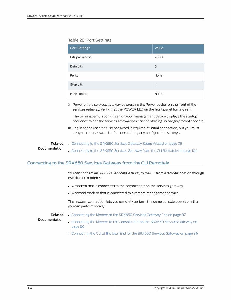
Table 28: Port Settings
ValuePort Settings
9600Bits per second
8Data bits
NoneParity
1Stop bits
NoneFlow control
9. Power on the services gateway by pressing the Power button on the front of the
services gateway. Verify that the POWER LED on the front panel turns green.
The terminal emulation screen on your management device displays the startup
sequence. When the services gateway has finished starting up, a login prompt appears.
10. Log in as the user root. No password is required at initial connection, but you must
assign a root password before committing any configuration settings.
RelatedDocumentation
Connecting to the SRX650 Services Gateway Setup Wizard on page 98•
• Connecting to the SRX650 Services Gateway from the CLI Remotely on page 104
Connecting to the SRX650 Services Gateway from the CLI Remotely
You can connect an SRX650 Services Gateway to the CLI from a remote location through
two dial-up modems:
• A modem that is connected to the console port on the services gateway
• A second modem that is connected to a remote management device
The modem connection lets you remotely perform the same console operations that
you can perform locally.
RelatedDocumentation
Connecting the Modem at the SRX650 Services Gateway End on page 87•
• Connecting the Modem to the Console Port on the SRX650 Services Gateway on
page 86
• Connecting the CLI at the User End for the SRX650 Services Gateway on page 86
Copyright © 2016, Juniper Networks, Inc.104
SRX650 Services Gateway Hardware Guide
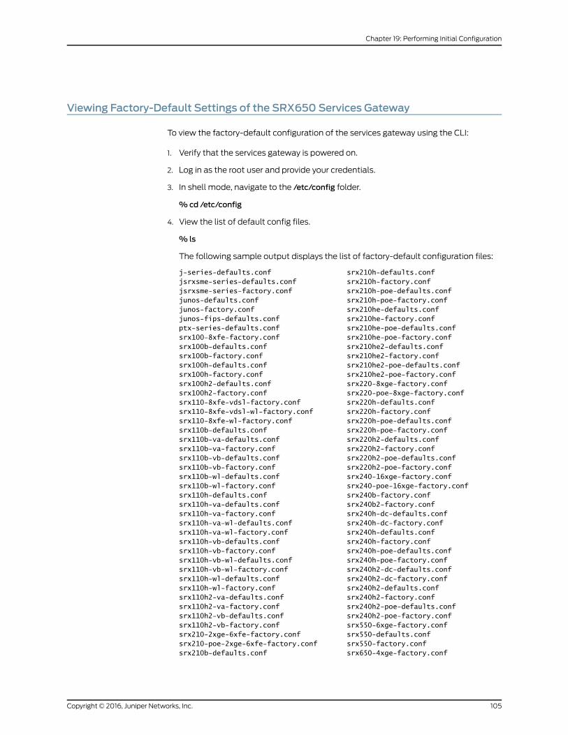
Viewing Factory-Default Settings of the SRX650 Services Gateway
To view the factory-default configuration of the services gateway using the CLI:
1. Verify that the services gateway is powered on.
2. Log in as the root user and provide your credentials.
3. In shell mode, navigate to the /etc/config folder.
%cd /etc/config
4. View the list of default config files.
% ls
The following sample output displays the list of factory-default configuration files:
j-series-defaults.conf srx210h-defaults.confjsrxsme-series-defaults.conf srx210h-factory.confjsrxsme-series-factory.conf srx210h-poe-defaults.confjunos-defaults.conf srx210h-poe-factory.confjunos-factory.conf srx210he-defaults.confjunos-fips-defaults.conf srx210he-factory.confptx-series-defaults.conf srx210he-poe-defaults.confsrx100-8xfe-factory.conf srx210he-poe-factory.confsrx100b-defaults.conf srx210he2-defaults.confsrx100b-factory.conf srx210he2-factory.confsrx100h-defaults.conf srx210he2-poe-defaults.confsrx100h-factory.conf srx210he2-poe-factory.confsrx100h2-defaults.conf srx220-8xge-factory.confsrx100h2-factory.conf srx220-poe-8xge-factory.confsrx110-8xfe-vdsl-factory.conf srx220h-defaults.confsrx110-8xfe-vdsl-wl-factory.conf srx220h-factory.confsrx110-8xfe-wl-factory.conf srx220h-poe-defaults.confsrx110b-defaults.conf srx220h-poe-factory.confsrx110b-va-defaults.conf srx220h2-defaults.confsrx110b-va-factory.conf srx220h2-factory.confsrx110b-vb-defaults.conf srx220h2-poe-defaults.confsrx110b-vb-factory.conf srx220h2-poe-factory.confsrx110b-wl-defaults.conf srx240-16xge-factory.confsrx110b-wl-factory.conf srx240-poe-16xge-factory.confsrx110h-defaults.conf srx240b-factory.confsrx110h-va-defaults.conf srx240b2-factory.confsrx110h-va-factory.conf srx240h-dc-defaults.confsrx110h-va-wl-defaults.conf srx240h-dc-factory.confsrx110h-va-wl-factory.conf srx240h-defaults.confsrx110h-vb-defaults.conf srx240h-factory.confsrx110h-vb-factory.conf srx240h-poe-defaults.confsrx110h-vb-wl-defaults.conf srx240h-poe-factory.confsrx110h-vb-wl-factory.conf srx240h2-dc-defaults.confsrx110h-wl-defaults.conf srx240h2-dc-factory.confsrx110h-wl-factory.conf srx240h2-defaults.confsrx110h2-va-defaults.conf srx240h2-factory.confsrx110h2-va-factory.conf srx240h2-poe-defaults.confsrx110h2-vb-defaults.conf srx240h2-poe-factory.confsrx110h2-vb-factory.conf srx550-6xge-factory.confsrx210-2xge-6xfe-factory.conf srx550-defaults.confsrx210-poe-2xge-6xfe-factory.conf srx550-factory.confsrx210b-defaults.conf srx650-4xge-factory.conf
105Copyright © 2016, Juniper Networks, Inc.
Chapter 19: Performing Initial Configuration

srx210b-factory.conf srx650-defaults.confsrx210be-defaults.conf srx650-factory.confsrx210be-factory.conf
5. View the required default config file.
%vi config file name
For example, enter the following command to view the default configuration file for
the SRX240 Services Gateway.
%vi srx240-poe-16xge-factory.conf
The following sample output displays the factory-default configuration on an SRX240
Services Gateway:
#### $Id: $#### Copyright (c) 2009, Juniper Networks, Inc.## All rights reserved.##system { autoinstallation { delete-upon-commit; traceoptions { level verbose; flag { all; } } interfaces { ge-0/0/0 { bootp; } } } services { ssh; telnet; dhcp { router { 192.168.1.1; } pool 192.168.1.0/24 { address-range low 192.168.1.2 high 192.168.1.254; } propagate-settings ge-0/0/0.0; } web-management { http { interface [ vlan.0 ]; } https { system-generated-certificate; interface [ vlan.0 ]; } } xnm-clear-text; } name-server { 208.67.222.222;
Copyright © 2016, Juniper Networks, Inc.106
SRX650 Services Gateway Hardware Guide
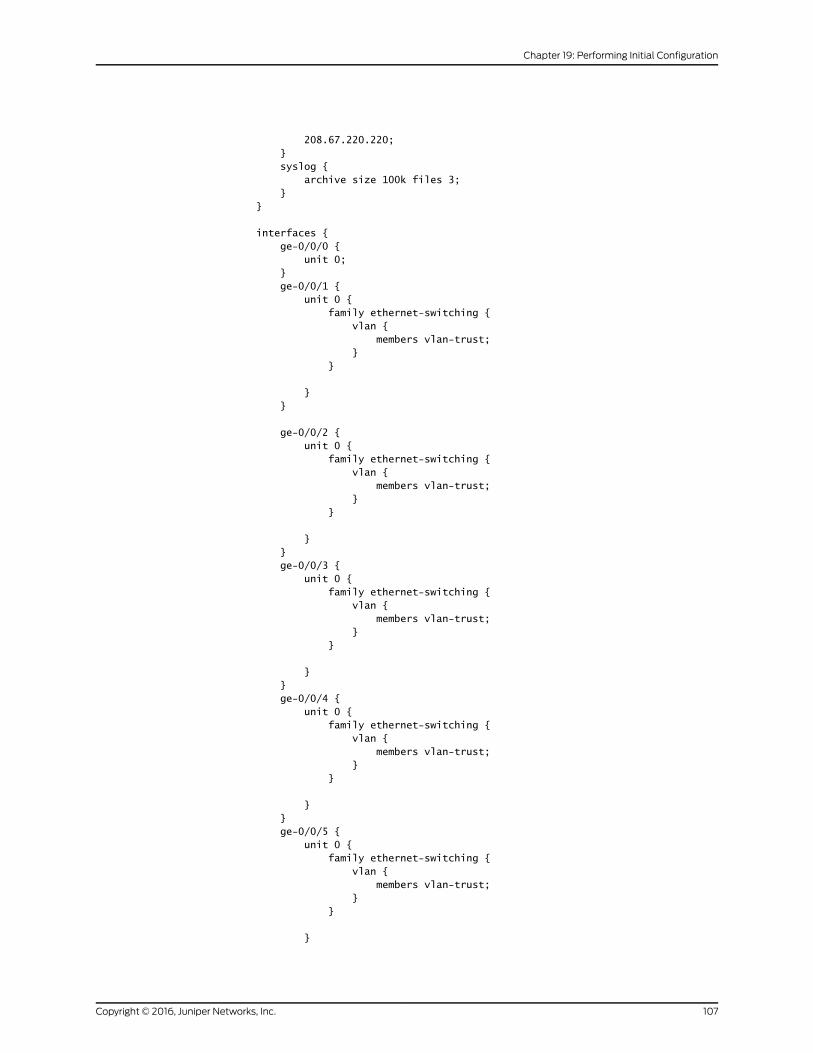
208.67.220.220; } syslog { archive size 100k files 3; }}
interfaces { ge-0/0/0 { unit 0; } ge-0/0/1 { unit 0 { family ethernet-switching { vlan { members vlan-trust; } }
} }
ge-0/0/2 { unit 0 { family ethernet-switching { vlan { members vlan-trust; } }
} } ge-0/0/3 { unit 0 { family ethernet-switching { vlan { members vlan-trust; } }
} } ge-0/0/4 { unit 0 { family ethernet-switching { vlan { members vlan-trust; } }
} } ge-0/0/5 { unit 0 { family ethernet-switching { vlan { members vlan-trust; } }
}
107Copyright © 2016, Juniper Networks, Inc.
Chapter 19: Performing Initial Configuration

} ge-0/0/6 { unit 0 { family ethernet-switching { vlan { members vlan-trust; } }
} } ge-0/0/7 { unit 0 { family ethernet-switching { vlan { members vlan-trust; } }
} } ge-0/0/8 { unit 0 { family ethernet-switching { vlan { members vlan-trust; } }
} } ge-0/0/9 { unit 0 { family ethernet-switching { vlan { members vlan-trust; } }
} } ge-0/0/10 { unit 0 { family ethernet-switching { vlan { members vlan-trust; } }
} } ge-0/0/11 { unit 0 { family ethernet-switching { vlan { members vlan-trust; } }
} }
Copyright © 2016, Juniper Networks, Inc.108
SRX650 Services Gateway Hardware Guide

ge-0/0/12 { unit 0 { family ethernet-switching { vlan { members vlan-trust; } }
} } ge-0/0/13 { unit 0 { family ethernet-switching { vlan { members vlan-trust; } }
} } ge-0/0/14 { unit 0 { family ethernet-switching { vlan { members vlan-trust; } }
} } ge-0/0/15 { unit 0 { family ethernet-switching { vlan { members vlan-trust; } }
} } vlan { unit 0 { family inet { address 192.168.1.1/24; } } }}
poe { interface all;}
security { nat { source { rule-set trust-to-untrust { from zone trust; to zone untrust; rule source-nat-rule { match {
109Copyright © 2016, Juniper Networks, Inc.
Chapter 19: Performing Initial Configuration
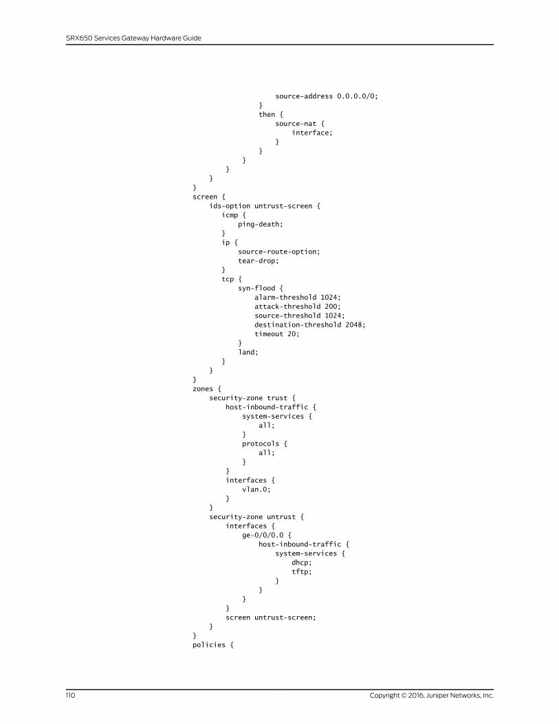
source-address 0.0.0.0/0; } then { source-nat { interface; } } } } } } screen { ids-option untrust-screen { icmp { ping-death; } ip { source-route-option; tear-drop; } tcp { syn-flood { alarm-threshold 1024; attack-threshold 200; source-threshold 1024; destination-threshold 2048; timeout 20; } land; } } } zones { security-zone trust { host-inbound-traffic { system-services { all; } protocols { all; } } interfaces { vlan.0; } } security-zone untrust { interfaces { ge-0/0/0.0 { host-inbound-traffic { system-services { dhcp; tftp; } } } } screen untrust-screen; } } policies {
Copyright © 2016, Juniper Networks, Inc.110
SRX650 Services Gateway Hardware Guide
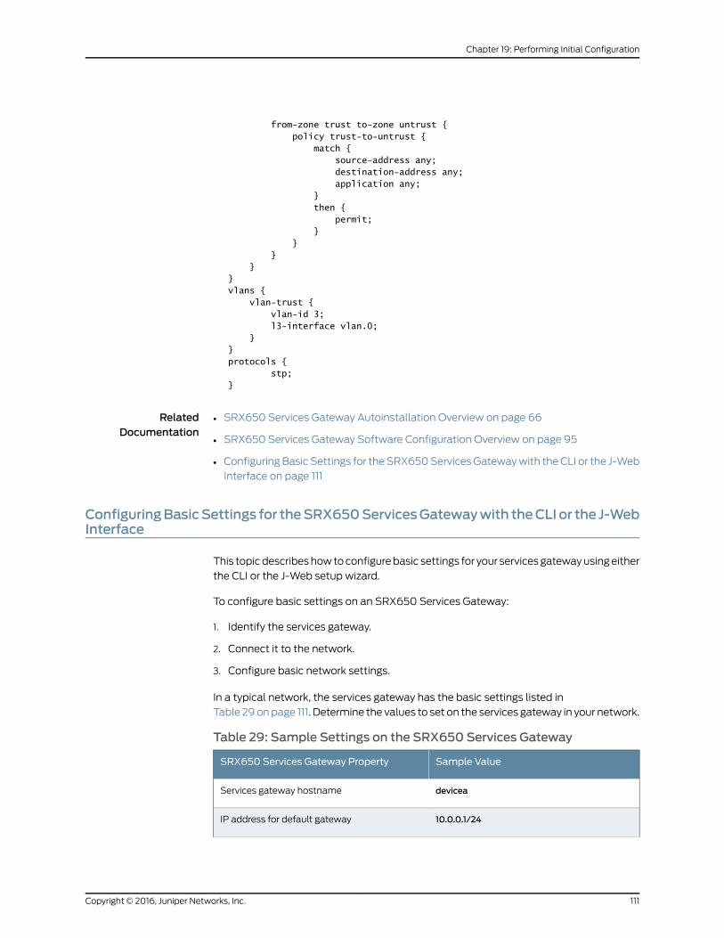
from-zone trust to-zone untrust { policy trust-to-untrust { match { source-address any; destination-address any; application any; } then { permit; } } } }}vlans { vlan-trust { vlan-id 3; l3-interface vlan.0; }}protocols { stp;}
RelatedDocumentation
SRX650 Services Gateway Autoinstallation Overview on page 66•
• SRX650 Services Gateway Software Configuration Overview on page 95
• Configuring Basic Settings for the SRX650 Services Gateway with the CLI or the J-Web
Interface on page 111
ConfiguringBasicSettings for theSRX650ServicesGatewaywith theCLI or the J-WebInterface
This topic describes how to configure basic settings for your services gateway using either
the CLI or the J-Web setup wizard.
To configure basic settings on an SRX650 Services Gateway:
1. Identify the services gateway.
2. Connect it to the network.
3. Configure basic network settings.
In a typical network, the services gateway has the basic settings listed in
Table 29 on page 111. Determine the values to set on the services gateway in your network.
Table 29: Sample Settings on the SRX650 Services Gateway
Sample ValueSRX650 Services Gateway Property
deviceaServices gateway hostname
10.0.0.1/24IP address for default gateway
111Copyright © 2016, Juniper Networks, Inc.
Chapter 19: Performing Initial Configuration
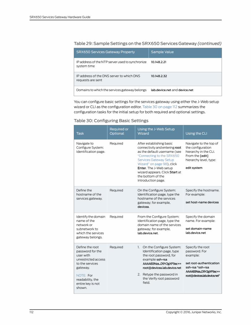
Table29:SampleSettingson theSRX650ServicesGateway (continued)
Sample ValueSRX650 Services Gateway Property
10.148.2.21IP address of the NTP server used to synchronizesystem time
10.148.2.32IP address of the DNS server to which DNSrequests are sent
lab.device.net and device.netDomains to which the services gateway belongs
You can configure basic settings for the services gateway using either the J-Web setup
wizard or CLI as the configuration editor. Table 30 on page 112 summarizes the
configuration tasks for the initial setup for both required and optional settings.
Table 30: Configuring Basic Settings
Using the CLIUsing the J-Web SetupWizard
Required orOptionalTask
Navigate to the top ofthe configurationhierarchy in the CLI.From the [edit]hierarchy level, type:
edit system
After establishing basicconnectivity and entering rootas the default username (see“Connecting to the SRX650Services Gateway SetupWizard” on page 98), clickEnter. The J-Web setupwizard appears. ClickStart atthe bottom of theIntroduction page.
RequiredNavigate toConfigure System:Identification page.
Specify the hostname.For example:
set host-name devicea
On the Configure System:Identification page, type thehostname of the servicesgateway; for example,devicea.
RequiredDefine thehostname of theservices gateway.
Specify the domainname. For example:
set domain-namelab.device.net
From the Configure System:Identification page, type thedomain name of the servicesgateway; for example,lab.device.net.
RequiredIdentify the domainname of thenetwork orsubnetwork towhich the servicesgateway belongs.
Specify the rootpassword. Forexample:
set root-authenticationssh-rsa “[email protected]”
1. On the Configure System:Identification page, typethe root password, forexample [email protected]
2. Retype the password inthe Verify root passwordfield.
RequiredDefine the rootpassword for theuser withunrestricted accessto the servicesgateway.
NOTE: Forreadability, theentire key is notshown.
Copyright © 2016, Juniper Networks, Inc.112
SRX650 Services Gateway Hardware Guide

Table 30: Configuring Basic Settings (continued)
Using the CLIUsing the J-Web SetupWizard
Required orOptionalTask
Set the defaultgateway IP addressand the next-hoprouter address. Forexample:
set interfaces ge-0/0/1unit 0 family inetaddress 10.0.0.1/24
set routing-optionsstatic route 0.0.0.0/0next-hop 10.0.0.2
NOTE: The exampleassumes that thenext-hop routeraddress is 10.0.0.2.
From the Configure System:Network Settings page, typethe IP address of the defaultgateway; for example,10.0.0.1/24.
OptionalDefine the IPaddress of thedefault gateway.The defaultgateway is the IPaddress and subnetof the next-hoprouter, which isgenerally providedby the ISP for abranch office.
Specify the address ofthe DNS server. Forexample:
set name-server10.148.2.32
From the Configure System:Network Settings page, typethe IP address of the DNSserver; for example,10.148.2.32. Then click Add.
OptionalAdd the names ofservers thatmaintain databasesfor resolvinghostnames and IPaddresses.
Specify the domains tobe searched. Forexample:
set domain-searchlab.device.net
set domain-searchdevice.net
From the Configure System:Network Settings page, typethe domains to be searched;for example, lab.device.netanddevice.net. Then clickAddafter each one you add to thelist.
OptionalAdd each domainto which theservices gatewaybelongs, to includeit in a DNS search.
Specify a VLANinterface. For example:
set interfaces ge-0/0/1unit 0 family inetaddress 10.148.1.32
From the Interface Groups(VLANs) page, clickAdd,Edit,orDelete to configure VLANs.
OptionalConfigure interfacegroups (VLANs).
Specify an interfaceother than a VLANinterface. For example:
set interfaces ge-0/0/2unit 0 family inetaddress 10.148.5.32
From the Configure Interfacespage, click Add, Edit, orDelete to configure interfacesother than VLANs.
OptionalConfigureinterfaces otherthan VLANs.
113Copyright © 2016, Juniper Networks, Inc.
Chapter 19: Performing Initial Configuration

Table 30: Configuring Basic Settings (continued)
Using the CLIUsing the J-Web SetupWizard
Required orOptionalTask
N/AFrom the Configure J-WebPreferences page, from theJ-Web starting page options,select the tab you want toappear on startup.
RequiredSpecify the tab youwant to appear onstartup.
N/AFrom the Configure J-WebPreferences page, from theJ-Web commit options,specify when you wantcommit to occur.
RequiredThe ConfigureJ-Web Preferencespage appearsbefore theConfigure System:Time page in thewizard. Specifywhen you wantcommit to occur.
Specify the time zone.For example:
set time-zoneAmerica/Los_Angeles
1. From the ConfigureSystem: Time page, clickReset Manually to resetthe time.
2. From the Time Zone list,select the time zone foryour services gateway; forexample,America/Los_Angeles
OptionalDefine the currentsystem time andtime zone in whichthe servicesgateway is located.
Specify the address ofthe NTP server. Forexample:
set ntp server10.148.2.21
From the Configure System:Time page, in the NTP Serversfield, type the NTP server's IPaddress; for example,10.148.2.21.
OptionalDefine the NTPserver that theservices gatewaycan reach tosynchronize thesystem time.
Commit and save yourconfiguration. Forexample:
commit
Review the configuration onthe Review & Commit page.Click Commit to save theconfiguration, or clickBack tomake changes.
RequiredCommit theconfiguration.
NOTE: After basic setup is configured, the J-Web setupwizardwill no longerbe available unless you reset the services gateway to the factory defaultsettings and reboot it. You can perform additional setup by using the J-Webinterface or the CLI interface. You can use wizards to configure basic firewallpolicies, VPN settings, and NAT rules. For more information about thesewizards, see the Security Basics.
Copyright © 2016, Juniper Networks, Inc.114
SRX650 Services Gateway Hardware Guide

For more instructions on managing users and operations, monitoring network performance,
upgrading software, and diagnosing common problems on an SRX650 Services Gateway,
see the Monitoring and Troubleshooting for Security Devices.
RelatedDocumentation
SRX650 Services Gateway Software Configuration Overview on page 95•
• Connecting to the SRX650 Services Gateway from the CLI Locally on page 102
• Connecting to the SRX650 Services Gateway from the CLI Remotely on page 104
• Connecting to the SRX650 Services Gateway Setup Wizard on page 98
• Displaying Basic Connectivity Configurations for the SRX650 Services Gateway on
page 115
Displaying Basic Connectivity Configurations for the SRX650 Services Gateway
To verify that the SRX650 Services Gateway has the settings you configured, you should
display the basic connectivity configurations. Because the basic connectivity settings
appear in different places in the configuration hierarchy, displaying the entire configuration
at once makes viewing the settings easier.
To display and verify the basic connectivity settings, select Configure>SystemProperties>System Identity. Alternatively, from configuration mode in the CLI, enter the
show command. Review the following sample output. Your output displays the values
you set.
[edit]user@host# showsystem {host-name devicea;domain-name lab.device.net;domain-search [ lab.device.net device.net ];time-zone America/Boston;root-authentication {ssh-rsa "ssh-rsa [email protected]";
}name-server {10.148.2.32;
}services {}ntp {server 10.148.2.21;
}}interfaces {ge-0/0/0 {unit 0 {family inet {address 10.157.71.12/19;
}}
}
115Copyright © 2016, Juniper Networks, Inc.
Chapter 19: Performing Initial Configuration

lo0 {unit 0 {family inet {address 127.0.0.1/32;address 10.254.71.12/32 {primary;
}} family iso {address 47.0005.80ff.f800.0000.0108.0001.0102.5407.1012.00;
}} family inet6 {address abcd::10:254:71:12/128 {primary;
}}
}
The output shows a basic connectivity configuration. Verify that the values displayed are
correct for your services gateway.
RelatedDocumentation
SRX650 Services Gateway Software Configuration Overview on page 95•
• Performing Initial Software Configuration on the SRX650 Services Gateway Using the
SetupWizard
• Configuring Basic Settings for the SRX650 Services Gateway with the CLI or the J-Web
Interface on page 111
Built-In Ethernet Ports for the SRX650 Services Gateway
You perform initial device setup through the four built-in Gigabit Ethernet ports,ge-0/0/0
through ge-0/0/3, on the front panel of the SRX650 Services Gateway.
NOTE: If chassis clustering is enabled, we recommend using the ge-0/0/0
port as themanagement port (fxp0) and using the ge-0/0/1port (if used) as
the control port (fxp1). The fxp0and fxp1ports are createdonlywhen chassis
clustering is enabled. You can use the other ports as fabric ports.
Before initial configuration, when the factory default configuration is active, the services
gateway attempts to perform autoinstallation by obtaining a device configuration through
all its connected interfaces, including ge-0/0/0. All interfaces are configured as Layer 3
interfaces. See Table 31 on page 117 for the default interface configuration.
Copyright © 2016, Juniper Networks, Inc.116
SRX650 Services Gateway Hardware Guide
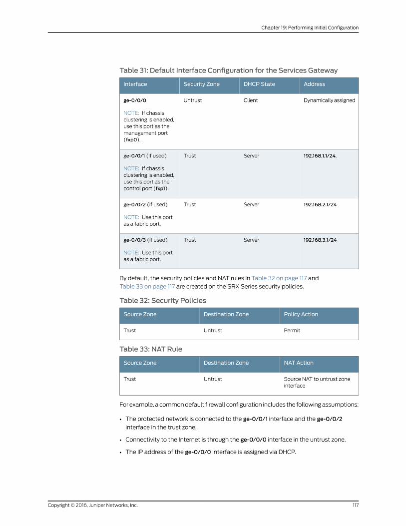
Table 31: Default Interface Configuration for the Services Gateway
AddressDHCP StateSecurity ZoneInterface
Dynamically assignedClientUntrustge-0/0/0
NOTE: If chassisclustering is enabled,use this port as themanagement port(fxp0).
192.168.1.1/24.ServerTrustge-0/0/1 (if used)
NOTE: If chassisclustering is enabled,use this port as thecontrol port (fxp1).
192.168.2.1/24ServerTrustge-0/0/2 (if used)
NOTE: Use this portas a fabric port.
192.168.3.1/24ServerTrustge-0/0/3 (if used)
NOTE: Use this portas a fabric port.
By default, the security policies and NAT rules in Table 32 on page 117 and
Table 33 on page 117 are created on the SRX Series security policies.
Table 32: Security Policies
Policy ActionDestination ZoneSource Zone
PermitUntrustTrust
Table 33: NAT Rule
NAT ActionDestination ZoneSource Zone
Source NAT to untrust zoneinterface
UntrustTrust
For example, a common default firewall configuration includes the following assumptions:
• The protected network is connected to the ge-0/0/1 interface and the ge-0/0/2
interface in the trust zone.
• Connectivity to the Internet is through the ge-0/0/0 interface in the untrust zone.
• The IP address of the ge-0/0/0 interface is assigned via DHCP.
117Copyright © 2016, Juniper Networks, Inc.
Chapter 19: Performing Initial Configuration
NOTE: Thege-0/0/1 interfaceandge-0/0/2 interfaceareapartof thedefault
VLAN. The protected hosts can be connected to any one of the ports thatare part of the default VLAN.
You can configure the services gateway using the CLI or J-Web. To use J-Web, connect
a desktop or laptop computer to the ge-0/0/1 interface. The IP address of the desktop
or laptop computer can be statically configured or assigned by the factory default DHCP
server enabled on the VLAN interface.
After you connect your desktop or laptop computer to ge-0/0/1, you can use a Web
browser to visit the address http://192.168.1.1, access the J-Web setup wizard, and
complete the initial setup configuration of the services gateway.
After you perform the initial configuration and commit it by clickingCommit, the configured
services gateway can no longer act as a DHCP server. Therefore, to continue using the
services gateway as a management interface, you should configure the IP address of the
interface as part of the initial configuration.
After the initial configuration is complete, you can attach the built-in Ethernet port that
you are using for management purposes to the management network.
RelatedDocumentation
• Connecting to the SRX650 Services Gateway Setup Wizard on page 98
• Connecting to the SRX650 Services Gateway from the CLI Locally on page 102
• Connecting to the SRX650 Services Gateway from the CLI Remotely on page 104
• SRX650 Services Gateway Software Configuration Overview on page 95
Copyright © 2016, Juniper Networks, Inc.118
SRX650 Services Gateway Hardware Guide
PART 4
Maintaining and TroubleshootingComponents
• Maintaining Components on page 121
• Troubleshooting Components on page 123
119Copyright © 2016, Juniper Networks, Inc.

Copyright © 2016, Juniper Networks, Inc.120
SRX650 Services Gateway Hardware Guide
CHAPTER 20
Maintaining Components
• Required Tools and Parts for Maintaining the SRX650 Services Gateway Hardware
Components on page 121
• Routine Maintenance Procedures for the SRX650 Services Gateway on page 121
• Maintaining the SRX650 Services Gateway Cooling System Components on page 122
• Maintaining the SRX650 Services Gateway Power Supply on page 122
Required Tools and Parts for Maintaining the SRX650 Services Gateway HardwareComponents
The following tools and parts are required to maintain the hardware components of the
services gateway:
• Electrostatic bag or antistatic mat
• Electrostatic discharge (ESD) grounding wrist strap
• Flat-blade screw-blade screwdriver, approximately 1/8 in. (3 mm)
• Phillips (+) screwdrivers, number 1 and number 2
RelatedDocumentation
Routine Maintenance Procedures for the SRX650 Services Gateway on page 121•
• Maintaining the SRX650 Services Gateway Cooling System Components on page 122
• Maintaining the SRX650 Services Gateway Power Supply on page 122
RoutineMaintenance Procedures for the SRX650 Services Gateway
For optimum performance of the services gateway, perform the following preventive
maintenance procedures regularly:
• Inspect the installation site for moisture, loose wires or cables, and excessive dust.
• Make sure that airflow is unobstructed around the services gateway and into the air
intake vents.
• Check the status LEDs on the front panel of the services gateway, the back panel, and
on the Services and Routing Engine (SRE) you are using.
121Copyright © 2016, Juniper Networks, Inc.

RelatedDocumentation
Required Tools and Parts for Maintaining the SRX650 Services Gateway Hardware
Components on page 121
•
• Maintaining the SRX650 Services Gateway Cooling System Components on page 122
• Maintaining the SRX650 Services Gateway Power Supply on page 122
Maintaining the SRX650 Services Gateway Cooling SystemComponents
The services gateway fan controller works to maintain an optimal temperature for the
services gateway. If the fan controller fails, the services gateway temperature will exceed
the maximum working temperature and it will fail. Make sure that you maintain the
recommended clearances behind the services gateway to enable the fan controller to
function optimally.
RelatedDocumentation
Required Tools and Parts for Maintaining the SRX650 Services Gateway Hardware
Components on page 121
•
• Routine Maintenance Procedures for the SRX650 Services Gateway on page 121
• SRX650 Services Gateway Environmental Specifications on page 42
• Maintaining the SRX650 Services Gateway Power Supply on page 122
Maintaining the SRX650 Services Gateway Power Supply
To maintain the power supplies of the services gateway:
• Make sure that all power and grounding cables are arranged so that they do not obstruct
access to other services gateway components.
• Routinely check the POWER LED on the front panel. If this LED is solid green, the power
supplies are functioning normally.
• Periodically inspect the site to ensure that the grounding and power cables connected
to the services gateway are securely in place and that there is no moisture accumulating
near the services gateway.
RelatedDocumentation
• Required Tools and Parts for Maintaining the SRX650 Services Gateway Hardware
Components on page 121
• Routine Maintenance Procedures for the SRX650 Services Gateway on page 121
• Maintaining the SRX650 Services Gateway Cooling System Components on page 122
Copyright © 2016, Juniper Networks, Inc.122
SRX650 Services Gateway Hardware Guide
CHAPTER 21
Troubleshooting Components
• Troubleshooting with the CLI on the SRX650 Services Gateway on page 123
• Troubleshooting with LEDs on the SRX650 Services Gateway on page 123
• Troubleshooting with Chassis and Interface Alarm Messages on the SRX650 Services
Gateway on page 127
• Troubleshooting the Power System on the SRX650 Services Gateway on page 129
• Using the RESET CONFIG Button on the SRX650 Services Gateway on page 132
• Changing the RESET CONFIG Button Behavior on the SRX650 Services
Gateway on page 133
• Resetting the SRX650 Services Gateway on page 133
Troubleshooting with the CLI on the SRX650 Services Gateway
The Junos OS command-line interface (CLI) is the primary tool for controlling and
troubleshooting services gateway hardware, the Junos OS, routing protocols, and network
connectivity. The CLI commands display information from routing tables, information
specific to routing protocols, and information about network connectivity derived from
the ping and trace route utilities.
You need to enter the CLI commands on one or more external management devices
connected to the services gateway to display the information.
RelatedDocumentation
SRX650 Services Gateway Front Panel on page 18•
• SRX650 Services Gateway Services and Routing Engine 6 on page 11
• Troubleshooting with Chassis and Interface Alarm Messages on the SRX650 Services
Gateway on page 127
• Troubleshooting the Power System on the SRX650 Services Gateway on page 129
• Changing the RESET CONFIG Button Behavior on the SRX650 Services Gateway on
page 133
Troubleshooting with LEDs on the SRX650 Services Gateway
The LEDs available on the services gateway display the status of various components.
Table 34 on page 124describes the LEDs on the chassis. To view LED information on the
123Copyright © 2016, Juniper Networks, Inc.

Services and Routing Engine (SRE), see “SRX650 Services Gateway Services and Routing
Engine 6” on page 11.
Table 34: Component LEDs on the Services Gateway Chassis
UsageLocationLED
The POWER LED has the followingindicator colors:
• Green and steadily on indicatesthat all power supply units(PSUs) are functioning normally.
• Red and steadily on indicatesfailure of one or more PSUs.
• Amber and steadily on indicatesthat the Power button has beenpressed. The services gatewaywill shut down gracefully.
• Off indicates that the device isnot receiving power.
Left side of the front chassispanel
POWER
The FAN LED has the followingindicator colors:
• Green and steadily on indicatesfan tray is functioning normally.
• Red and steadily on indicates fantray failure.
• Off indicates no fan tray.
Left side of the front chassispanel
FAN
The ALARM LED has the followingindicator colors:
• Red and steadily on indicates ahardware component orsoftware module failure, ordetection of a firewall attack.
• Amber and steadily on indicatesa major alarm, such as lowmemory (less than 10%remaining), session full,maximum number of VPNtunnels reached, HA statuschange, or redundant groupmember not found.
• Off indicates that the device isstarting up.
NOTE: When the system is running,if the ALARM LED is off, it indicatesthat no alarms are present on thedevice.
Left side of the front chassispanel
ALARM
Copyright © 2016, Juniper Networks, Inc.124
SRX650 Services Gateway Hardware Guide
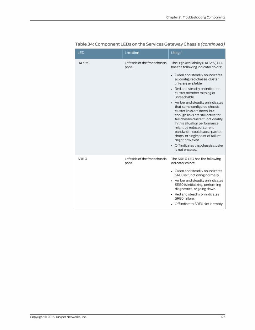
Table34:Component LEDson theServicesGatewayChassis (continued)
UsageLocationLED
The High Availability (HA SYS) LEDhas the following indicator colors:
• Green and steadily on indicatesall configured chassis clusterlinks are available.
• Red and steadily on indicatescluster member missing orunreachable.
• Amber and steadily on indicatesthat some configured chassiscluster links are down, butenough links are still active forfull chassis cluster functionality.In this situation performancemight be reduced, currentbandwidth could cause packetdrops, or single point of failuremight now exist.
• Off indicates that chassis clusteris not enabled.
Left side of the front chassispanel
HA SYS
The SRE 0 LED has the followingindicator colors:
• Green and steadily on indicatesSRE0 is functioning normally.
• Amber and steadily on indicatesSRE0 is initializing, performingdiagnostics, or going down.
• Red and steadily on indicatesSRE0 failure.
• Off indicates SRE0 slot is empty.
Left side of the front chassispanel
SRE 0
125Copyright © 2016, Juniper Networks, Inc.
Chapter 21: Troubleshooting Components
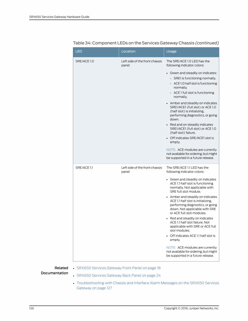
Table34:Component LEDson theServicesGatewayChassis (continued)
UsageLocationLED
The SRE/ACE 1.0 LED has thefollowing indicator colors:
• Green and steadily on indicates:
• SRE1 is functioning normally.
• ACE 1.0 half slot is functioningnormally.
• ACE 1 full slot is functioningnormally.
• Amber and steadily on indicatesSRE1/ACE1 (full slot) or ACE 1.0(half slot) is initializing,performing diagnostics, or goingdown.
• Red and on steadily indicatesSRE1/ACE1 (full slot) or ACE 1.0(half slot) failure.
• Off indicates SRE/ACE1 slot isempty.
NOTE: ACE modules are currentlynot available for ordering, but mightbe supported in a future release.
Left side of the front chassispanel
SRE/ACE 1.0
The SRE/ACE 1.1 LED has thefollowing indicator colors:
• Green and steadily on indicatesACE 1.1 half slot is functioningnormally. Not applicable withSRE full slot module.
• Amber and steadily on indicatesACE 1.1 half slot is initializing,performing diagnostics, or goingdown. Not applicable with SREor ACE full slot modules.
• Red and steadily on indicatesACE 1.1 half slot failure. Notapplicable with SRE or ACE fullslot modules.
• Off indicates ACE 1.1 half slot isempty.
NOTE: ACE modules are currentlynot available for ordering, but mightbe supported in a future release.
Left side of the front chassispanel
SRE/ACE 1.1
RelatedDocumentation
SRX650 Services Gateway Front Panel on page 18•
• SRX650 Services Gateway Back Panel on page 24
• Troubleshooting with Chassis and Interface Alarm Messages on the SRX650 Services
Gateway on page 127
Copyright © 2016, Juniper Networks, Inc.126
SRX650 Services Gateway Hardware Guide
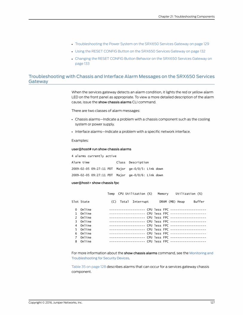
• Troubleshooting the Power System on the SRX650 Services Gateway on page 129
• Using the RESET CONFIG Button on the SRX650 Services Gateway on page 132
• Changing the RESET CONFIG Button Behavior on the SRX650 Services Gateway on
page 133
Troubleshootingwith Chassis and Interface AlarmMessages on the SRX650ServicesGateway
When the services gateway detects an alarm condition, it lights the red or yellow alarm
LED on the front panel as appropriate. To view a more detailed description of the alarm
cause, issue the show chassis alarms CLI command.
There are two classes of alarm messages:
• Chassis alarms—Indicate a problem with a chassis component such as the cooling
system or power supply.
• Interface alarms—Indicate a problem with a specific network interface.
Examples:
user@host# run show chassis alarms
4 alarms currently active
Alarm time Class Description
2009-02-05 09:27:11 PDT Major ge-0/0/5: Link down
2009-02-05 09:27:11 PDT Major ge-0/0/6: Link down
user@host> show chassis fpc
Temp CPU Utilization (%) Memory Utilization (%)
Slot State (C) Total Interrupt DRAM (MB) Heap Buffer
0 Online -------------------- CPU less FPC -------------------- 1 Online -------------------- CPU less FPC -------------------- 2 Online -------------------- CPU less FPC -------------------- 3 Online -------------------- CPU less FPC -------------------- 4 Online -------------------- CPU less FPC -------------------- 5 Online -------------------- CPU less FPC -------------------- 6 Online -------------------- CPU less FPC -------------------- 7 Online -------------------- CPU less FPC -------------------- 8 Online -------------------- CPU less FPC --------------------
For more information about the show chassis alarms command, see the Monitoring and
Troubleshooting for Security Devices.
Table 35 on page 128 describes alarms that can occur for a services gateway chassis
component.
127Copyright © 2016, Juniper Networks, Inc.
Chapter 21: Troubleshooting Components
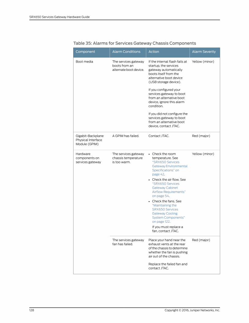
Table 35: Alarms for Services Gateway Chassis Components
Alarm SeverityActionAlarm ConditionsComponent
Yellow (minor)If the internal flash fails atstartup, the servicesgateway automaticallyboots itself from thealternative boot device(USB storage device).
If you configured yourservices gateway to bootfrom an alternative bootdevice, ignore this alarmcondition.
If you did not configure theservices gateway to bootfrom an alternative bootdevice, contact JTAC.
The services gatewayboots from analternate boot device.
Boot media
Red (major)Contact JTAC.A GPIM has failed.Gigabit-BackplanePhysical InterfaceModule (GPIM)
Yellow (minor)• Check the roomtemperature. See“SRX650 ServicesGateway EnvironmentalSpecifications” onpage 42.
• Check the air flow. See“SRX650 ServicesGateway CabinetAirflow Requirements”on page 54.
• Check the fans. See“Maintaining theSRX650 ServicesGateway CoolingSystem Components”on page 122.
If you must replace afan, contact JTAC.
The services gatewaychassis temperatureis too warm.
Hardwarecomponents onservices gateway
Red (major)Place your hand near theexhaust vents at the rearof the chassis to determinewhether the fan is pushingair out of the chassis.
Replace the failed fan andcontact JTAC.
The services gatewayfan has failed.
Copyright © 2016, Juniper Networks, Inc.128
SRX650 Services Gateway Hardware Guide
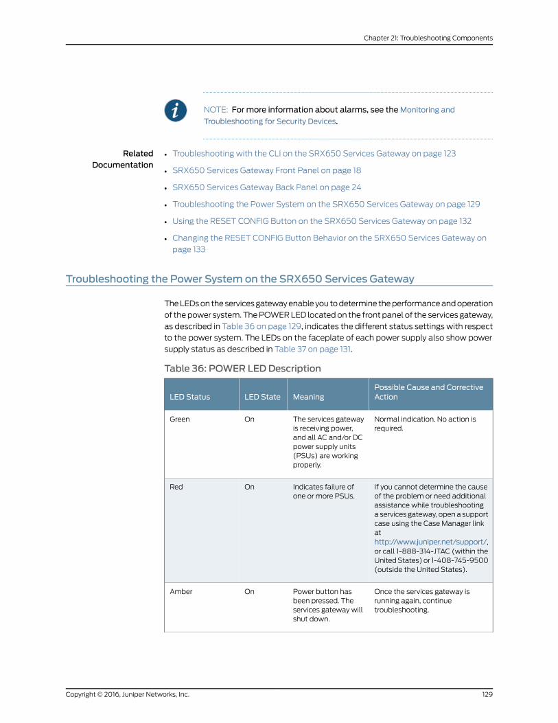
NOTE: For more information about alarms, see theMonitoring and
Troubleshooting for Security Devices.
RelatedDocumentation
Troubleshooting with the CLI on the SRX650 Services Gateway on page 123•
• SRX650 Services Gateway Front Panel on page 18
• SRX650 Services Gateway Back Panel on page 24
• Troubleshooting the Power System on the SRX650 Services Gateway on page 129
• Using the RESET CONFIG Button on the SRX650 Services Gateway on page 132
• Changing the RESET CONFIG Button Behavior on the SRX650 Services Gateway on
page 133
Troubleshooting the Power System on the SRX650 Services Gateway
The LEDs on the services gateway enable you to determine the performance and operation
of the power system. The POWER LED located on the front panel of the services gateway,
as described in Table 36 on page 129, indicates the different status settings with respect
to the power system. The LEDs on the faceplate of each power supply also show power
supply status as described in Table 37 on page 131.
Table 36: POWER LED Description
Possible Cause and CorrectiveActionMeaningLED StateLED Status
Normal indication. No action isrequired.
The services gatewayis receiving power,and all AC and/or DCpower supply units(PSUs) are workingproperly.
OnGreen
If you cannot determine the causeof the problem or need additionalassistance while troubleshootinga services gateway, open a supportcase using the Case Manager linkathttp://www.juniper.net/support/,or call 1-888-314-JTAC (within theUnited States) or 1-408-745-9500(outside the United States).
Indicates failure ofone or more PSUs.
OnRed
Once the services gateway isrunning again, continuetroubleshooting.
Power button hasbeen pressed. Theservices gateway willshut down.
OnAmber
129Copyright © 2016, Juniper Networks, Inc.
Chapter 21: Troubleshooting Components

Table 36: POWER LED Description (continued)
Possible Cause and CorrectiveActionMeaningLED StateLED Status
If a red alarm condition occurs,issue the show chassis alarmscommand to determine the sourceof the problem.
• Verify that the AC power cordand/or DC power supply cableis not damaged. If the insulationis cracked or broken,immediately replace the cord orcable.
• Verify that the source circuitbreaker has the proper currentrating. Each power supply mustbe connected to a separatesource circuit breaker.
• Ensure that the power socketyou are plugged into is in workingcondition.
• Connect the power supply to adifferent power source with anew power cord or power cables.If the power supply status LEDsindicate that the power supplyis not functioning normally, thepower supply is the source of theproblem. Replace the powersupply with a spare.
NOTE: If the system temperatureexceeds the threshold, the JunosOS shuts down all power suppliesso that no status is displayed.
The Junos OS also can shut downone of the power supplies for otherreasons. In this case, the remainingpower supplies provide power tothe services gateway, and you canstill view the system status throughthe CLI.
Indicates that theservices gateway isnot receiving power.
Off
Copyright © 2016, Juniper Networks, Inc.130
SRX650 Services Gateway Hardware Guide
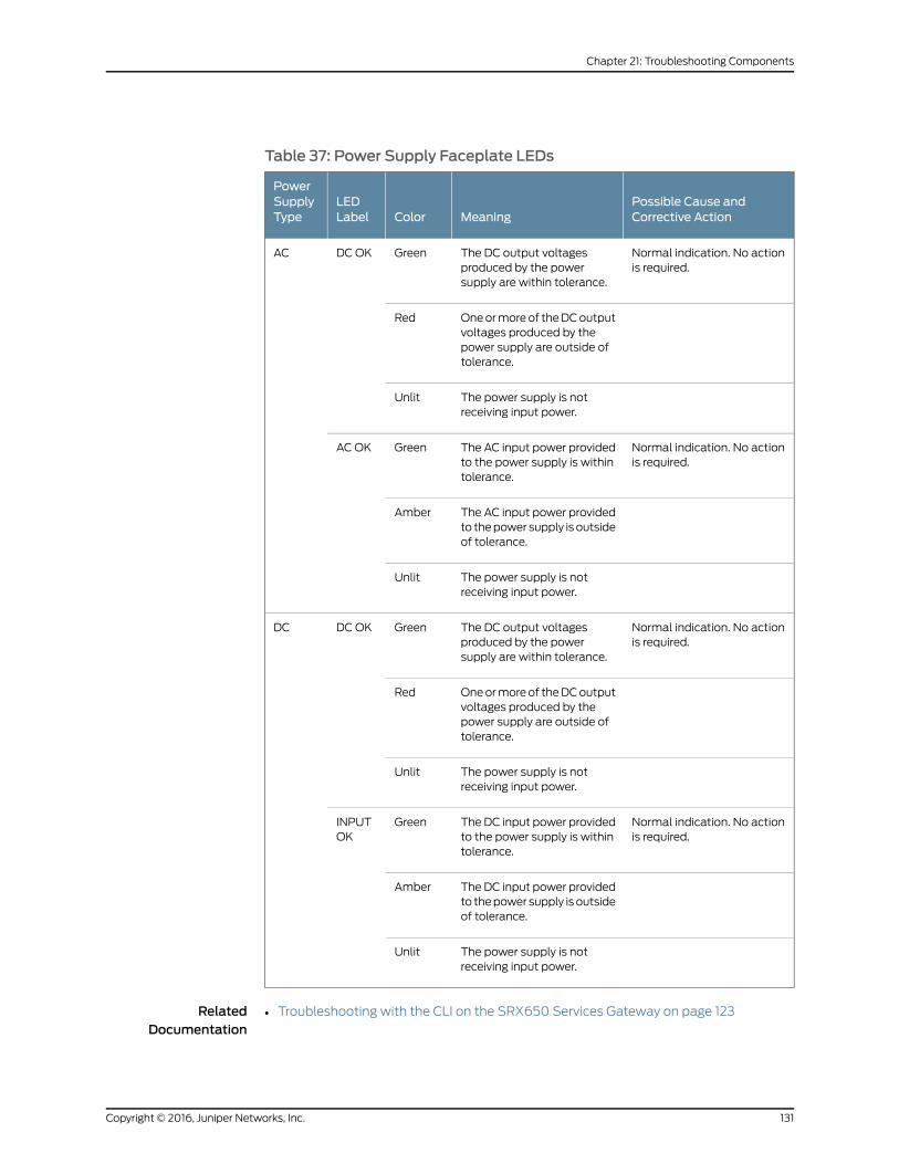
Table 37: Power Supply Faceplate LEDs
Possible Cause andCorrective ActionMeaningColor
LEDLabel
PowerSupplyType
Normal indication. No actionis required.
The DC output voltagesproduced by the powersupply are within tolerance.
GreenDC OKAC
One or more of the DC outputvoltages produced by thepower supply are outside oftolerance.
Red
The power supply is notreceiving input power.
Unlit
Normal indication. No actionis required.
The AC input power providedto the power supply is withintolerance.
GreenAC OK
The AC input power providedto the power supply is outsideof tolerance.
Amber
The power supply is notreceiving input power.
Unlit
Normal indication. No actionis required.
The DC output voltagesproduced by the powersupply are within tolerance.
GreenDC OKDC
One or more of the DC outputvoltages produced by thepower supply are outside oftolerance.
Red
The power supply is notreceiving input power.
Unlit
Normal indication. No actionis required.
The DC input power providedto the power supply is withintolerance.
GreenINPUTOK
The DC input power providedto the power supply is outsideof tolerance.
Amber
The power supply is notreceiving input power.
Unlit
RelatedDocumentation
Troubleshooting with the CLI on the SRX650 Services Gateway on page 123•
131Copyright © 2016, Juniper Networks, Inc.
Chapter 21: Troubleshooting Components

• Troubleshooting with Chassis and Interface Alarm Messages on the SRX650 Services
Gateway on page 127
• Removing an AC Power Supply from the SRX650 Services Gateway on page 141
• SRX650 Services Gateway Front Panel on page 18
• SRX650 Services Gateway Back Panel on page 24
Using the RESET CONFIG Button on the SRX650 Services Gateway
If a configuration fails or denies management access to the services gateway, you can
use the RESET CONFIG button to restore the services gateway to the factory default
configuration or a rescue configuration. For example, if someone inadvertently commits
a configuration that denies management access to a services gateway, you can delete
the invalid configuration and replace it with a rescue configuration by pressing the RESET
CONFIG button. The button is recessed to prevent it from being pressed accidentally.
The rescue configuration is a previously committed, valid configuration. You must have
previously set the rescue configuration through the J-Web interface or the CLI.
To press the RESET CONFIG button, insert a small probe (such as a straightened paper
clip) into the pinhole on the front panel.
CAUTION:
Bydefault, pressing andquickly releasing theRESETCONFIGbutton loadsand commits the rescue configuration through the J-Web interface or theCLI. (For details, see the CLI Explorer.)
•
• By default, pressing and holding the RESETCONFIG button for 15 secondsor more—until the STATUS LED blinks red—deletes all configurations onthe services gateway, including the backup configurations and rescueconfiguration, and loads and commits the factory configuration.
For details about factory-default settings, see “Viewing Factory-Default Settings of the
SRX650 Services Gateway” on page 105.
For details about performing initial software configuration, see “Configuring Basic Settings
for the SRX650 Services Gateway with the CLI or the J-Web Interface” on page 111.
RelatedDocumentation
Changing the RESET CONFIG Button Behavior on the SRX650 Services Gateway on
page 133
•
• Troubleshooting with LEDs on the SRX650 Services Gateway on page 123
• Troubleshooting with Chassis and Interface Alarm Messages on the SRX650 Services
Gateway on page 127
• Troubleshooting the Power System on the SRX650 Services Gateway on page 129
• Resetting the SRX650 Services Gateway on page 133
Copyright © 2016, Juniper Networks, Inc.132
SRX650 Services Gateway Hardware Guide

• SRX650 Services Gateway Front Panel on page 18
Changing the RESET CONFIG Button Behavior on the SRX650 Services Gateway
You can change the default operation of the RESET CONFIG button of the SRX Services
Gateway by limiting how the button resets the services gateway:
• To prevent the RESET CONFIG button from setting the services gateway to the factory
default configuration and deleting all other configurations, enter the following
command. You can still press and quickly release the button to reset it to the rescue
configuration.
user@host# set chassis config-button no-clear
• To prevent the RESET CONFIG button from setting the services gateway to the rescue
configuration, enter the following command. You can still press and hold the button
for 15 seconds or more to reset the services gateway to the factory defaults.
user@host# set chassis config-button no-rescue
• To disable the button and prevent the services gateway from resetting to either
configuration, enter the following command:
user@host# set chassis config-button no-clear no-rescue
The no-rescue option prevents the RESET CONFIG button from loading the rescue
configuration. The no-clear option prevents the RESET CONFIG button from deleting all
configurations on the services gateway.
To return the function of the RESET CONFIG button to its default behavior, remove the
config-button statement from the services gateway configuration.
RelatedDocumentation
Resetting the SRX650 Services Gateway on page 133•
• Troubleshooting with the CLI on the SRX650 Services Gateway on page 123
• Using the RESET CONFIG Button on the SRX650 Services Gateway on page 132
• SRX650 Services Gateway Front Panel on page 18
• Troubleshooting the Power System on the SRX650 Services Gateway on page 129
Resetting the SRX650 Services Gateway
Use the RESET CONFIG button to return the services gateway to either the rescue
configuration or the factory default configuration. The button is recessed to prevent it
from being pressed accidentally. To press this button, insert a small probe (such as a
straightened paper clip) into the pinhole on the SRE on the back panel of the chassis
(see “SRX650 Services Gateway Services and Routing Engine 6” on page 11).
For example, if someone inadvertently commits a configuration that denies management
access to a services gateway, you can delete the invalid configuration and replace it with
a rescue configuration by pressing the RESET CONFIG button. You must have previously
133Copyright © 2016, Juniper Networks, Inc.
Chapter 21: Troubleshooting Components

set the rescue configuration through J-Web or the CLI. The rescue configuration is a
previously committed, valid configuration.
CAUTION: Pressing and holding the RESET CONFIG button for 15 secondsor more—until the STATUS LED blinks red—deletes all configurations on theservices gateway, including the backup configurations and rescueconfiguration, and loads and commits the factory configuration.
There are two types of reset:
• Power On—This reset occurs during the services gateway powering on and powering
off. This reset is issued when the services gateway is first powered on. The system
accesses the configuration settings from the boot flash for this type of reset.
• Config—This reset is the asynchronous reset input to the services gateway. The RESET
CONFIG button is used to generate a reset to load the default configuration settings
from the kernel. The system accesses the default factory settings from the internal
flash for this type of reset.
RelatedDocumentation
• Grounding the SRX650 Services Gateway on page 82
• Powering On the SRX650 Services Gateway on page 92
• Powering Off the SRX650 Services Gateway on page 93
• SRX650 Services Gateway Front Panel on page 18
Copyright © 2016, Juniper Networks, Inc.134
SRX650 Services Gateway Hardware Guide
PART 5
Replacing Components
• Overview of Replacing Components on page 137
• Replacing the Services and Routing Engine (SRE) Module on page 139
• Replacing Power System Components on page 141
• Replacing Cooling System Components on page 147
• Contacting Customer Support and Returning Components on page 151
135Copyright © 2016, Juniper Networks, Inc.

Copyright © 2016, Juniper Networks, Inc.136
SRX650 Services Gateway Hardware Guide

CHAPTER 22
Overview of Replacing Components
• Required Tools and Parts for Replacing Hardware Components on the SRX650 Services
Gateway on page 137
RequiredToolsandParts forReplacingHardwareComponentsontheSRX650ServicesGateway
To replace hardware components, you need the tools and parts listed in
Table 38 on page 137.
Table 38: Tools and Parts Required for Replacing Services GatewayHardware Components
ComponentsTool or Part
Cables and connectors3/8 in. nut driver or pliers
Power supplySRE and multi-use processorGPIMs
Blank panels (if component is not reinstalled)
SREGPIMs
Electrostatic bag or antistatic mat
AllElectrostatic discharge (ESD) grounding wriststrap
Cables and connectorsFlat-blade (–) screwdriver
Air filterCables and connectorsBlank panelsFan trayGPIMsSRE
Phillips (+) screwdrivers, numbers 1 and 2
Cables and connectorsWire cutters
RelatedDocumentation
• Removing the Fan Tray on the SRX650 Services Gateway on page 147
• Removing the SRE from the SRX650 Services Gateway on page 139
137Copyright © 2016, Juniper Networks, Inc.

• Removing the Air Filter on the SRX650 Services Gateway on page 148
• Removing an AC Power Supply from the SRX650 Services Gateway on page 141
• Removing a DC Power Supply on the SRX650 Services Gateway on page 143
Copyright © 2016, Juniper Networks, Inc.138
SRX650 Services Gateway Hardware Guide

CHAPTER 23
Replacing theServicesandRoutingEngine(SRE) Module
• Removing the SRE from the SRX650 Services Gateway on page 139
Removing the SRE from the SRX650 Services Gateway
The SRE is located at the back panel of the chassis and can be installed in the horizontal
slots labeled SRE0 or SRE1.0/1.1. The SRE weighs 3 lb, 13.6 oz (1.75 kg).
CAUTION: The SRE is not hot-swappable. Youmust power off the servicesgateway before removing or inserting an SRE.
To remove the SRE:
1. Obtain an electrostatic bag to store the SRE after you remove it.
2. Attach an electrostatic discharge (ESD) grounding strap to your bare wrist, and connect
the strap to the ESD point on the chassis.
3. Power off the services gateway.
4. Use a number 2 Phillips screwdriver to loosen the captive screws on each side of the
SRE.
5. Grasp the locking levers on each side of the SRE and pull toward you to unlock the
SRE (see Figure 23 on page 140).
6. Slide the SRE out and place it in the electrostatic bag.
7. If you are not replacing the SRE, install a blank panel over the empty slot.
139Copyright © 2016, Juniper Networks, Inc.

Figure 23: Removing the Services and Routing Engine (SRE)
g032
708
RelatedDocumentation
• SRX650 Services Gateway Back Panel on page 24
• Installing the SRE on the SRX650 Services Gateway on page 77
• SRX650 Services Gateway Services and Routing Engine 6 on page 11
• Powering Off the SRX650 Services Gateway on page 93
Copyright © 2016, Juniper Networks, Inc.140
SRX650 Services Gateway Hardware Guide

CHAPTER 24
Replacing Power System Components
• Removing an AC Power Supply from the SRX650 Services Gateway on page 141
• Disconnecting an AC Power Cord from the SRX650 Services Gateway on page 142
• Removing a DC Power Supply on the SRX650 Services Gateway on page 143
• Removing a DC Power Supply Cable from the SRX650 Services Gateway on page 144
Removing an AC Power Supply from the SRX650 Services Gateway
Up to two power supplies can be located at the rear of the chassis on the right side. Each
AC power supply weighs 2 lb, 14.6 oz (1.32 kg).
CAUTION: Donot leave a power supply slot empty formore than 30minuteswhile theservicesgateway isoperational. Forproperairflow, thepowersupplymust remain in the chassis, or a blank panel must be used in an empty slot.
NOTE: After powering off a power supply, wait at least 60 seconds beforeturning it back on.
To remove an AC power supply:
1. Switch off the dedicated facility circuit breaker for the power supply, and remove the
power cord from the AC power source. Follow the electrostatic discharge (ESD) and
disconnection instructions for your site.
2. Attach an ESD grounding strap to your bare wrist and connect the strap to one of the
ESD points on the chassis. For more information about ESD, see “Preventing
Electrostatic Discharge Damage to the SRX650 Services Gateway” on page 164.
3. Press the latch to the left of the power outlet (see Figure 24 on page 142).
4. After the power supply is unlatched, remove the power cord from the power supply.
5. Pull the power supply straight out of the chassis.
141Copyright © 2016, Juniper Networks, Inc.

Figure 24: Removing an AC Power Supply from the SRX650 ServicesGateway
g032
711
RelatedDocumentation
Installing an AC Power Supply on the SRX650 Services Gateway on page 78•
• Required Tools and Parts for Replacing Hardware Components on the SRX650 Services
Gateway on page 137
• Disconnecting an AC Power Cord from the SRX650 Services Gateway on page 142
Disconnecting an AC Power Cord from the SRX650 Services Gateway
WARNING: BeforeworkingonanAC-powereddeviceor nearpower supplies,unplug the power cord.
To disconnect the AC power cord:
1. Unplug the power cord from the power source receptacle.
2. Attach an electrostatic discharge (ESD) grounding strap to your bare wrist and connect
the strap to one of the ESD points on the chassis. For more information about ESD,
see “Preventing Electrostatic Discharge Damage to the SRX650 Services Gateway”
on page 164.
3. Unplug the power cord from the appliance inlet on the power supply.
RelatedDocumentation
Connecting an AC Power Cord to the SRX650 Services Gateway on page 90•
• Removing an AC Power Supply from the SRX650 Services Gateway on page 141
• Required Tools and Parts for Replacing Hardware Components on the SRX650 Services
Gateway on page 137
Copyright © 2016, Juniper Networks, Inc.142
SRX650 Services Gateway Hardware Guide

Removing a DC Power Supply on the SRX650 Services Gateway
Up to two power supplies can be located at the rear of the chassis on the right side. Each
DC power supply weighs approximately 2 lbs, 13.4 oz (1.29 kg).
CAUTION: Donot leave a power supply slot empty formore than 30minuteswhile theservicesgateway isoperational. Forproperairflow, thepowersupplymust remain in the chassis, or a blank panel must be used in an empty slot.
NOTE: After powering off a power supply, wait at least 60 seconds beforeturning it back on.
To remove a DC power supply, see Figure 25 on page 144.
1. Switch off the dedicated facility circuit breaker for the power supply. Follow the
electrostatic discharge (ESD) and disconnection instructions for your site.
2. Make sure that the voltage across the DC power source cable leads is 0 V and that
there is no chance that the cables might become active during the removal process.
3. Attach an ESD grounding strap to your bare wrist and connect the strap to one of the
ESD points on the chassis. For more information about ESD, see “Preventing
Electrostatic Discharge Damage to the SRX650 Services Gateway” on page 164.
4. Remove the clear plastic cover protecting the terminal studs on the faceplate.
5. Remove the screws and washers from the terminals. Use a number 2 Phillips
screwdriver to loosen and remove the screws.
6. Remove the cable lugs from the terminal studs.
7. Carefully move the power cables out of the way.
8. Push the tab on the left edge of the power supply to the right.
9. Pull the power supply straight out of the chassis.
143Copyright © 2016, Juniper Networks, Inc.
Chapter 24: Replacing Power System Components

Figure 25: Removing a DC Power Supply from the SRX650 ServicesGateway
RelatedDocumentation
Required Tools and Parts for Replacing Hardware Components on the SRX650 Services
Gateway on page 137
•
• Installing a DC Power Supply on the SRX650 Services Gateway on page 79
• Removing a DC Power Supply Cable from the SRX650 Services Gateway on page 144
Removing a DC Power Supply Cable from the SRX650 Services Gateway
To remove a power supply cable connected to a DC power supply:
1. Attach an electrostatic discharge (ESD) grounding strap to your bare wrist and connect
the strap to an approved site ESD grounding point. For more information about ESD,
see “Preventing Electrostatic Discharge Damage to the SRX650 Services Gateway”
on page 164.
2. Switch off the external circuit breakers for all the cables attached to the power supply.
Make sure that the voltage across the DC power source cable leads is 0 V and that
there is no chance that the cables might become active during the removal process.
3. Remove the power cable from the DC power source.
4. Attach an ESD grounding strap to your bare wrist and connect the strap to one of the
ESD points on the chassis. For more information about ESD, see “Preventing
Electrostatic Discharge Damage to the SRX650 Services Gateway” on page 164.
5. Make sure the cable is not touching or in the way of any services gateway components
and that it does not drape where people could trip on it.
6. Remove the clear plastic cover protecting the terminal studs on the faceplate.
Copyright © 2016, Juniper Networks, Inc.144
SRX650 Services Gateway Hardware Guide

7. Attach the power cable to the DC power source.
8. Verify that the DC source power cabling is correct. If the power cable is correctly
installed and the power supply is functioning normally, the POWER LED on the front
panel lights green steadily.
RelatedDocumentation
• Required Tools and Parts for Replacing Hardware Components on the SRX650 Services
Gateway on page 137
• Removing a DC Power Supply on the SRX650 Services Gateway on page 143
• Installing a DC Power Supply on the SRX650 Services Gateway on page 79
145Copyright © 2016, Juniper Networks, Inc.
Chapter 24: Replacing Power System Components

Copyright © 2016, Juniper Networks, Inc.146
SRX650 Services Gateway Hardware Guide
CHAPTER 25
Replacing Cooling System Components
• Removing the Fan Tray on the SRX650 Services Gateway on page 147
• Removing the Air Filter on the SRX650 Services Gateway on page 148
Removing the Fan Tray on the SRX650 Services Gateway
A single handle with two screws holds both the fan tray and air filter on the back of the
services gateway. To remove the fan tray, you must also remove the air filter. See
Figure 26 on page 148.
1. Attach an electrostatic discharge (ESD) grounding strap to your bare wrist and connect
the strap to one of the ESD points on the side of the chassis. For more information
about ESD, see “Preventing Electrostatic Discharge Damage to the SRX650 Services
Gateway” on page 164.
2. Use a number 2 Phillips screwdriver to loosen and remove only the center screw of
the handle.
3. Grasp the fan tray handle and pull it out approximately 1 to 3 inches.
WARNING: Toavoid injury, keep tools and your fingers away from the fansas youslide the fan trayoutof thechassis. The fansmight still be spinning.
4. Press the latch located on the inside of the fan tray to release it from the chassis.
5. Place one hand under the fan tray to support it and carefully slide the fan tray (and
air filter) completely out of the chassis.
147Copyright © 2016, Juniper Networks, Inc.

Figure 26: Removing the Fan Tray from the Services Gateway
g032
715
RelatedDocumentation
Installing the Fan Tray on the SRX650 Services Gateway on page 75•
• Required Tools and Parts for Replacing Hardware Components on the SRX650 Services
Gateway on page 137
Removing the Air Filter on the SRX650 Services Gateway
NOTE: The SRX650 Services Gateway does not ship with an air filter. An airfilter must be purchased separately.
CAUTION: Exceptduring replacement, alwayskeep theair filter inplacewhilethe services gateway is operating. Because the fans are very powerful, theycould pull small bits of wire or other materials into the device through theunfiltered air intake. This could damage the components.
Copyright © 2016, Juniper Networks, Inc.148
SRX650 Services Gateway Hardware Guide

A single handle with two screws holds both the fan tray and air filter on the back of the
services gateway.
NOTE: You can replace the air filter while the services gateway is running.
To remove just the air filter:
1. Attach an electrostatic discharge (ESD) grounding strap to your bare wrist and connect
the strap to one of the ESD points on the chassis. For more information about ESD,
see “Preventing Electrostatic Discharge Damage to the SRX650 Services Gateway”
on page 164.
2. Use a number 1 Phillips screwdriver to loosen both captive screws on the handle (see
Figure 27 on page 149).
Figure 27: Loosening Captive Screws
g032
738
3. Carefully slide out the fan tray.
4. Remove just the air filter.
149Copyright © 2016, Juniper Networks, Inc.
Chapter 25: Replacing Cooling System Components
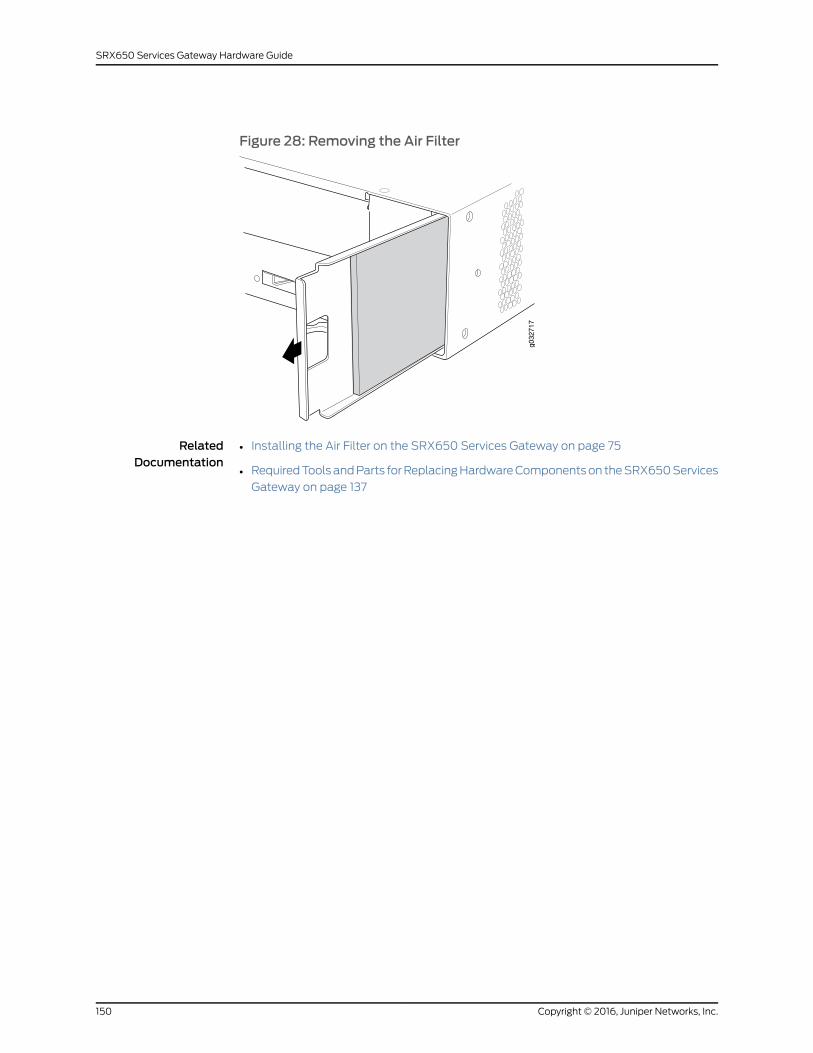
Figure 28: Removing the Air Filter
g032
717
RelatedDocumentation
• Installing the Air Filter on the SRX650 Services Gateway on page 75
• Required Tools and Parts for Replacing Hardware Components on the SRX650 Services
Gateway on page 137
Copyright © 2016, Juniper Networks, Inc.150
SRX650 Services Gateway Hardware Guide

CHAPTER 26
Contacting Customer Support andReturning Components
• Contacting Customer Support on page 151
• Return Procedure for the SRX650 Services Gateway on page 152
• Locating the SRX650 Services Gateway Chassis Serial Number and Agency
Labels on page 152
• Locating the SRX650 Services Gateway GPIM Serial Number Label on page 153
• Listing the SRX650 Services Gateway Component Details with the CLI on page 153
• Information You Might Need to Supply to JTAC on page 154
• Required Tools and Parts for Packing the SRX650 Services Gateway on page 154
• Packing the SRX650 Services Gateway for Shipment on page 155
• Packing the SRX650 Services Gateway Components for Shipment on page 156
Contacting Customer Support
Once you have located the serial numbers of the device or component, you can return
the device or component for repair or replacement. For this, you need to contact Juniper
Networks Technical Assistance Center (JTAC).
You can contact JTAC 24 hours a day, 7 days a week, using any of the following methods:
• On the Web: Using the Case Manager link at http://www.juniper.net/support/
• By telephone:
• From the US and Canada: 1-888-314-JTAC
• From all other locations: 1-408-745-9500
NOTE: If contacting JTAC by telephone, enter your 11-digit case numberfollowed by the pound (#) key if this is an existing case, or press the star(*) key to be routed to the next available support engineer.
151Copyright © 2016, Juniper Networks, Inc.
RelatedDocumentation
Return Procedure for the SRX650 Services Gateway on page 152•
• Listing the SRX650 Services Gateway Component Details with the CLI on page 153
• Locating the SRX650 Services Gateway Chassis Serial Number and Agency Labels on
page 152
• Packing the SRX650 Services Gateway for Shipment on page 155
• Packing the SRX650 Services Gateway Components for Shipment on page 156
Return Procedure for the SRX650 Services Gateway
To return an SRX650 Services Gateway or component to Juniper Networks for repair or
replacement:
1. Determine the part number and serial number of the services gateway or component.
2. Obtain a Return Materials Authorization (RMA) number from JTAC.
NOTE: Do not return the services gateway or any component to JuniperNetworksunlessyouhave firstobtainedanRMAnumber. JuniperNetworksreserves the right to refuse shipments that do not have an RMA. Refusedshipments are returned to the customer via collect freight.
3. Pack the SRX650 Services Gateway or component for shipping.
For more information about return and repair policies, see the customer support webpage
at http://www.juniper.net/support/guidelines.html.
For product problems or technical support issues, open a support case using the Case
Manager link athttp://www.juniper.net/support/or call 1-888-314-JTAC (within the United
States) or 1-408-745-9500 (outside the United States).
RelatedDocumentation
Listing the SRX650 Services Gateway Component Details with the CLI on page 153•
• Locating the SRX650 Services Gateway Chassis Serial Number and Agency Labels on
page 152
• Information You Might Need to Supply to JTAC on page 154
• Packing the SRX650 Services Gateway for Shipment on page 155
• Packing the SRX650 Services Gateway Components for Shipment on page 156
• Contacting Customer Support on page 151
Locating the SRX650 Services Gateway Chassis Serial Number and Agency Labels
The SRX650 Services Gateway serial number is located on the bottom of the device on
the compliance/agency label.
Copyright © 2016, Juniper Networks, Inc.152
SRX650 Services Gateway Hardware Guide
RelatedDocumentation
Return Procedure for the SRX650 Services Gateway on page 152•
• Listing the SRX650 Services Gateway Component Details with the CLI on page 153
• Contacting Customer Support on page 151
• Information You Might Need to Supply to JTAC on page 154
Locating the SRX650 Services Gateway GPIM Serial Number Label
Gigabit-Backplane Physical Interface Modules (GPIMs) are field-replaceable on the
SRX650 Services Gateway. Each GPIM has a unique serial number. The exact location
might be slightly different on different GPIMs (XPIMs or GPIMs), depending on the
placement of the components on the GPIM.
RelatedDocumentation
Return Procedure for the SRX650 Services Gateway on page 152•
• Listing the SRX650 Services Gateway Component Details with the CLI on page 153
• Contacting Customer Support on page 151
• Information You Might Need to Supply to JTAC on page 154
Listing the SRX650 Services Gateway Component Details with the CLI
Before contacting Juniper Networks to request a Return Materials Authorization (RMA),
you must find the serial number on the SRX650 Services Gateway or component.
To list all of the SRX650 Services Gateway components and their serial numbers, enter
the following command-line interface (CLI) command:
user@host> show chassis hardwareHardware inventory:Item Version Part number Serial number DescriptionChassis AJ2608AE0013 SRX650Midplane REV 02 710-023875 AJ2608AE0013 System IO REV 01 710-023209 SRXSME System IORouting Engine RE-SRXSME-SRE3FPC 0 FPCPIC 0 4x GE Base PIC
NOTE: In the show chassis hardware command, the Gigabit-Backplane
Physical InterfaceModule (GPIM) slot number is reportedasanFPCnumber,and the GPIM number (always 0) is reported as the PIC number.
Most components also have a serial number ID label attached to thecomponent body.
RelatedDocumentation
Return Procedure for the SRX650 Services Gateway on page 152•
• Locating the SRX650 Services Gateway Chassis Serial Number and Agency Labels on
page 152
153Copyright © 2016, Juniper Networks, Inc.
Chapter 26: Contacting Customer Support and Returning Components

• Contacting Customer Support on page 151
• Information You Might Need to Supply to JTAC on page 154
Information YouMight Need to Supply to JTAC
When requesting support from JTAC by telephone, be prepared to provide the following
information:
• Your existing case number, if you have one
• Details of the failure or problem
• Type of activity being performed on the services gateway when the problem occurred
• Configuration data displayed by one or more show commands
• Your name, organization name, telephone number, fax number, and shipping address
RelatedDocumentation
Return Procedure for the SRX650 Services Gateway on page 152•
• Listing the SRX650 Services Gateway Component Details with the CLI on page 153
• Locating the SRX650 Services Gateway Chassis Serial Number and Agency Labels on
page 152
• Packing the SRX650 Services Gateway for Shipment on page 155
• Packing the SRX650 Services Gateway Components for Shipment on page 156
• Contacting Customer Support on page 151
Required Tools and Parts for Packing the SRX650 Services Gateway
To remove the components from the SRX650 Services Gateway or to remove the services
gateway from a rack, you need the following tools and parts:
• Blank panels to cover empty slots
• Electrostatic bag or antistatic mat for each component
• Electrostatic discharge (ESD) grounding wrist strap
• Flat-blade screwdriver, approximately 1/4 in. (6 mm)
• Phillips (+) screwdrivers, numbers 1 and 2
RelatedDocumentation
Return Procedure for the SRX650 Services Gateway on page 152•
• Packing the SRX650 Services Gateway for Shipment on page 155
• Packing the SRX650 Services Gateway Components for Shipment on page 156
Copyright © 2016, Juniper Networks, Inc.154
SRX650 Services Gateway Hardware Guide
Packing the SRX650 Services Gateway for Shipment
To pack the SRX650 Services Gateway for shipment:
1. Retrieve the shipping carton and packing materials in which the services gateway was
originally shipped. If you do not have these materials, contact your Juniper Networks
representative about approved packaging materials.
2. Attach an electrostatic discharge (ESD) grounding strap to your bare wrist and connect
the strap to the ESD point on the chassis or to an outside ESD point if the device is
disconnected from earth ground. For more information about ESD, see “Preventing
Electrostatic Discharge Damage to the SRX650 Services Gateway” on page 164.
3. On the console or other management device connected to the services gateway, enter
the CLI operational mode and issue the following command to shut down the services
gateway software:
user@host> request system halt
Wait until a message appears on the console confirming that the operating system
has halted.
4. Shut down power to the services gateway by pressing the Power button on the front
of the services gateway.
5. Disconnect power from the services gateway.
6. Remove the cables that connect to all external devices.
7. Remove the SRE (and GPIMs, if any have been installed) from the services gateway.
8. If the services gateway is installed in a rack, have one person support the weight of
the services gateway while another person unscrews and removes the mounting
screws.
9. Place the services gateway in the shipping carton.
10. Cover the services gateway with an ESD bag, and place the packing foam on top of
and around the device.
11. Replace the accessory box on top of the packing foam.
12. Securely tape the box closed.
13. Write the Return Materials Authorization (RMA) number on the exterior of the box to
ensure proper tracking.
RelatedDocumentation
Return Procedure for the SRX650 Services Gateway on page 152•
• Packing the SRX650 Services Gateway Components for Shipment on page 156
• Required Tools and Parts for Packing the SRX650 Services Gateway on page 154
155Copyright © 2016, Juniper Networks, Inc.
Chapter 26: Contacting Customer Support and Returning Components
Packing the SRX650 Services Gateway Components for Shipment
Follow these guidelines for packing and shipping individual components of the services
gateway:
• When you return a component, make sure that it is adequately protected with packing
materials and packed so that the pieces are prevented from moving around inside the
carton.
• Use the original shipping materials if they are available.
• Place the individual component in an electrostatic bag.
• Write the Return Materials Authorization (RMA) number on the exterior of the box to
ensure proper tracking.
CAUTION: Do not stack any of the services gateway components duringpacking.
RelatedDocumentation
• Return Procedure for the SRX650 Services Gateway on page 152
• Packing the SRX650 Services Gateway for Shipment on page 155
• Required Tools and Parts for Packing the SRX650 Services Gateway on page 154
Copyright © 2016, Juniper Networks, Inc.156
SRX650 Services Gateway Hardware Guide

PART 6
Safety
• General Safety Guidelines and Warnings on page 159
• Fire Safety Requirements on page 167
• Laser and LED Safety Guidelines and Warnings on page 169
• Maintenance and Operational Safety Guidelines and Warnings on page 175
• Electrical Safety Guidelines and Warnings on page 183
• Agency Approvals and Regulatory Compliance Information on page 193
157Copyright © 2016, Juniper Networks, Inc.

Copyright © 2016, Juniper Networks, Inc.158
SRX650 Services Gateway Hardware Guide
CHAPTER 27
General Safety Guidelines andWarnings
• SRX650 Services Gateway Definition of Safety Warning Levels on page 159
• SRX650 Services Gateway General Safety Guidelines and Warnings on page 161
• SRX650 Services Gateway Safety Requirements, Warnings, and Guidelines on page 162
• Restricted Access Area Warning on page 162
• Qualified Personnel Warning on page 163
• Preventing Electrostatic Discharge Damage to the SRX650 Services
Gateway on page 164
SRX650 Services Gateway Definition of SafetyWarning Levels
This guide uses the following four levels of safety warnings:
NOTE: Youmight find this information helpful in a particular situation ormight otherwise overlook it.
CAUTION: You need to observe the specified guidelines to avoidminor injuryor discomfort to you or severe damage to the device.
WARNING: This symbol is used with laser warnings. Unterminated opticalconnectors can emit invisible laser radiation. Focusing your eye directly on alaser source—even a low-power laser—could permanently damage the eye.
WARNING: This symbolmeansdanger.Youare inasituation thatcouldcausebodily injury. Before you work on any equipment, be aware of the hazardsinvolved with electrical circuitry and be familiar with standard practices forpreventing accidents.
Waarschuwing Dit waarschuwingssymbool betekent gevaar. U verkeert ineen situatie die lichamelijk letsel kan veroorzaken. Voordat u aan enige
159Copyright © 2016, Juniper Networks, Inc.

apparatuur gaat werken, dient u zich bewust te zijn van de bij elektrischeschakelingen betrokken risico's en dient u opde hoogte te zijn van standaardmaatregelen om ongelukken te voorkomen.
Varoitus Tämä varoitusmerkki merkitsee vaaraa. Olet tilanteessa, joka voijohtaa ruumiinvammaan.Ennenkuin työskenteletminkään laitteistonparissa,ota selvää sähkökytkentöihin liittyvistä vaaroista ja tavanomaisistaonnettomuuksien ehkäisykeinoista.
AttentionCe symbole d'avertissement indique un danger. Vous vous trouvezdansunesituationpouvantcauserdesblessuresoudesdommagescorporels.Avant de travailler sur un équipement, soyez conscient des dangers poséspar les circuits électriques et familiarisez-vous avec les procédurescouramment utilisées pour éviter les accidents.
Warnung DiesesWarnsymbol bedeutet Gefahr. Sie befinden sich in einerSituation, die zu einer Körperverletzung führen könnte. Bevor Sie mit derArbeit an irgendeinemGerät beginnen, seien Sie sich der mit elektrischenStromkreisen verbundenen Gefahren und der Standardpraktiken zurVermeidung von Unfällen bewußt.
AvvertenzaQuesto simbolo di avvertenza indica un pericolo. La situazionepotrebbe causare infortuni alle persone. Prima di lavorare su qualsiasiapparecchiatura, occorre conoscere i pericoli relativi ai circuiti elettrici edessere al corrente delle pratiche standard per la prevenzione di incidenti.
AdvarselDette varselsymbolet betyr fare. Du befinner deg i en situasjon somkan føre til personskade. Før du utfører arbeid på utstyr, må du vareoppmerksom på de faremomentene som elektriske kretser innebærer, samtgjøre deg kjent med vanlig praksis når det gjelder å unngå ulykker.
Aviso Este símbolo de aviso indica perigo. Encontra-se numa situação quelhepoderá causar danos físicos. Antes de começar a trabalhar comqualquerequipamento, familiarize-se com os perigos relacionados com circuitoseléctricos, e com quaisquer práticas comuns que possam prevenir possíveisacidentes.
¡Atención! Este símbolo de aviso significa peligro. Existe riesgo para suintegridad física. Antes demanipular cualquier equipo, considerar los riesgosque entraña la corriente eléctrica y familiarizarse con los procedimientosestándar de prevención de accidentes.
Varning!Denna varningssymbol signalerar fara. Du befinner dig i en situationsom kan leda till personskada. Innan du utför arbete på någon utrustningmåste du varamedveten om farornamed elkretsar och känna till vanligtförfarande för att förebygga skador.
RelatedDocumentation
SRX650 Services Gateway General Safety Guidelines and Warnings on page 161•
Copyright © 2016, Juniper Networks, Inc.160
SRX650 Services Gateway Hardware Guide

• Preventing Electrostatic Discharge Damage to the SRX650 Services Gateway on
page 164
• SRX650 Services Gateway Fire Safety Requirements and Fire Suppression Equipment
on page 167
SRX650 Services Gateway General Safety Guidelines andWarnings
The following guidelines help ensure your safety and protect the services gateway from
damage. The list of guidelines might not address all potentially hazardous situations in
your working environment, so be alert and exercise good judgment at all times.
• Perform only the procedures explicitly described in this guide. Make sure that only
authorized service personnel perform other system services.
• Keep the area around the chassis clear and free from dust before, during, and after
installation.
• Keep tools away from areas where people could trip on them.
• Wear safety glasses if you are working under any conditions that could be hazardous
to your eyes.
• Do not perform any actions that create a potential hazard to people or make the
equipment unsafe.
• Never install or manipulate wiring during electrical storms.
• Never install electrical jacks in wet locations unless the jacks are specifically designed
for wet environments.
• Do not open or remove chassis covers or sheet metal parts unless instructions are
provided in this guide. Such an action could cause severe electrical shock.
• Do not push or force any objects through any opening in the chassis frame. Such an
action could result in electrical shock or fire.
• Avoid spilling liquid onto the services gateway chassis or onto any services gateway
component. Such an action could cause electrical shock or damage the services
gateway.
• Avoid touching uninsulated electrical wires or terminals that have not been
disconnected from their power source. Such an action could cause electrical shock.
RelatedDocumentation
SRX650 Services Gateway Definition of Safety Warning Levels on page 159•
• Preventing Electrostatic Discharge Damage to the SRX650 Services Gateway on
page 164
• SRX650 Services Gateway Fire Safety Requirements and Fire Suppression Equipment
on page 167
161Copyright © 2016, Juniper Networks, Inc.
Chapter 27: General Safety Guidelines and Warnings
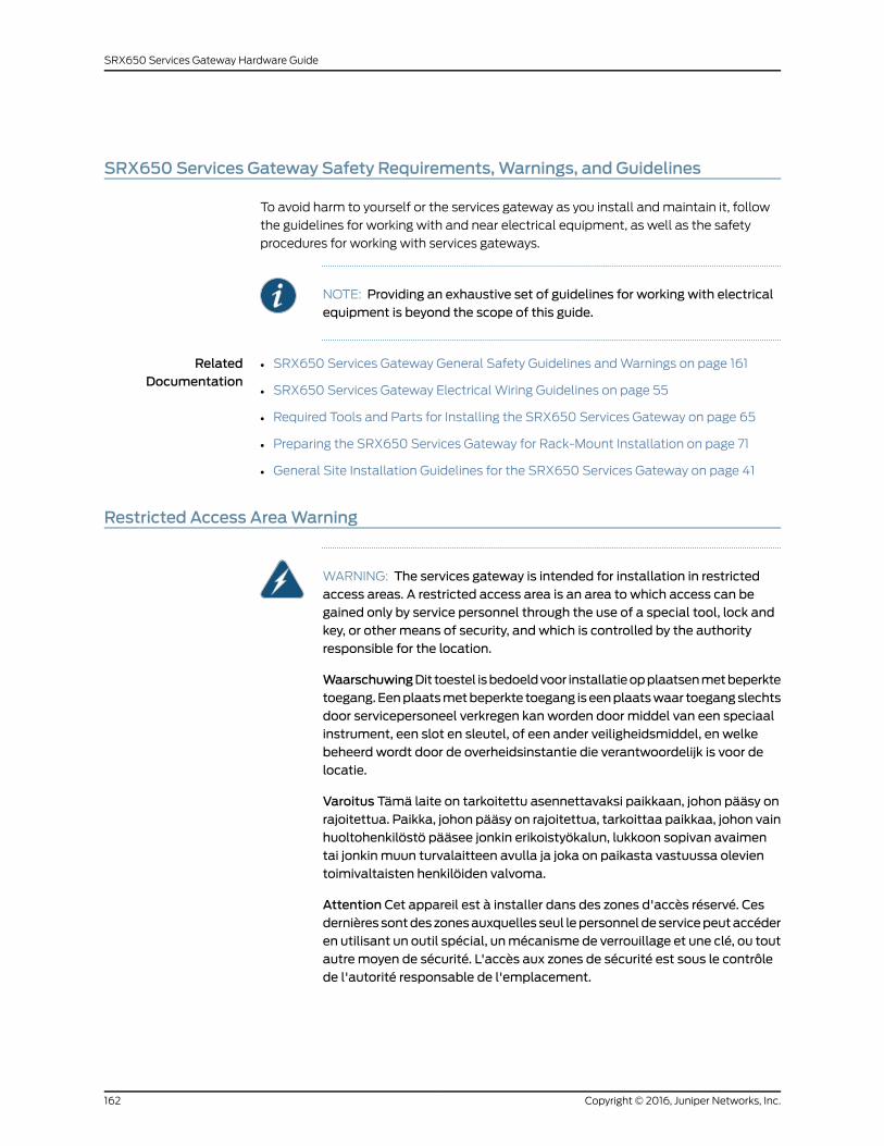
SRX650 Services Gateway Safety Requirements, Warnings, and Guidelines
To avoid harm to yourself or the services gateway as you install and maintain it, follow
the guidelines for working with and near electrical equipment, as well as the safety
procedures for working with services gateways.
NOTE: Providing an exhaustive set of guidelines for working with electricalequipment is beyond the scope of this guide.
RelatedDocumentation
SRX650 Services Gateway General Safety Guidelines and Warnings on page 161•
• SRX650 Services Gateway Electrical Wiring Guidelines on page 55
• Required Tools and Parts for Installing the SRX650 Services Gateway on page 65
• Preparing the SRX650 Services Gateway for Rack-Mount Installation on page 71
• General Site Installation Guidelines for the SRX650 Services Gateway on page 41
Restricted Access AreaWarning
WARNING: The services gateway is intended for installation in restrictedaccess areas. A restricted access area is an area to which access can begained only by service personnel through the use of a special tool, lock andkey, or other means of security, and which is controlled by the authorityresponsible for the location.
WaarschuwingDit toestel isbedoeldvoor installatieopplaatsenmetbeperktetoegang.Eenplaatsmetbeperkte toegang iseenplaatswaar toegangslechtsdoor servicepersoneel verkregen kan worden door middel van een speciaalinstrument, een slot en sleutel, of een ander veiligheidsmiddel, en welkebeheerd wordt door de overheidsinstantie die verantwoordelijk is voor delocatie.
Varoitus Tämä laite on tarkoitettu asennettavaksi paikkaan, johon pääsy onrajoitettua. Paikka, johon pääsy on rajoitettua, tarkoittaa paikkaa, johon vainhuoltohenkilöstö pääsee jonkin erikoistyökalun, lukkoon sopivan avaimentai jonkin muun turvalaitteen avulla ja joka on paikasta vastuussa olevientoimivaltaisten henkilöiden valvoma.
Attention Cet appareil est à installer dans des zones d'accès réservé. Cesdernières sontdeszonesauxquelles seul lepersonneldeservicepeutaccéderen utilisant un outil spécial, unmécanisme de verrouillage et une clé, ou toutautre moyen de sécurité. L'accès aux zones de sécurité est sous le contrôlede l'autorité responsable de l'emplacement.
Copyright © 2016, Juniper Networks, Inc.162
SRX650 Services Gateway Hardware Guide

Warnung Diese Einheit ist zur Installation in Bereichenmit beschränktemZutritt vorgesehen. Ein Bereichmit beschränktem Zutritt ist ein Bereich, zudem nurWartungspersonal mit einem Spezialwerkzeugs, Schloß undSchlüssel oder anderer Sicherheitsvorkehrungen Zugang hat, und der vondem für die Anlage zuständigen Gremium kontrolliert wird.
AvvertenzaQuestaunitàdeveessere installata inun'areaadaccesso limitato.Un'area ad accesso limitato è un'area accessibile solo a personale diassistenza tramite un'attrezzo speciale, lucchetto, o altri dispositivi disicurezza, ed è controllata dall'autorità responsabile della zona.
Advarsel Denne enheten er laget for installasjon i områder med begrensetadgang.Etområdemedbegrensetadganggir kunadgangtil servicepersonalesom bruker et spesielt verktøy, lås og nøkkel, eller en annensikkerhetsanordning, og det kontrolleres av den autoriteten som er ansvarligfor området.
AvisoEstaunidade foi concebidapara instalaçãoemáreasdeacesso restrito.Uma área de acesso restrito é uma área à qual apenas temacesso o pessoalde serviço autorizado, que possua uma ferramenta, chave e fechaduraespecial, ou qualquer outra forma de segurança. Esta área é controlada pelaautoridade responsável pelo local.
¡Atención! Esta unidad ha sido diseñada para instalarse en áreas de accesorestringido. Área de acceso restringido significa un área a la que solamentetieneaccesoelpersonaldeserviciomediante lautilizacióndeunaherramientaespecial, cerradura con llave, o algún otromedio de seguridad, y que estábajo el control de la autoridad responsable del local.
Varning! Denna enhet är avsedd för installation i områdenmed begränsattillträde. Ett områdemed begränsat tillträde får endast tillträdas avservicepersonal med ett speciellt verktyg, lås och nyckel, eller annansäkerhetsanordning, och kontrolleras av den auktoritet som ansvarar förområdet.
RelatedDocumentation
SRX650 Services Gateway General Safety Guidelines and Warnings on page 161•
• Qualified Personnel Warning on page 163
Qualified PersonnelWarning
WARNING: Only trainedandqualified personnel should install or replace theservices gateway.
Waarschuwing Installatie en reparaties mogen uitsluitend door getraind enbevoegd personeel uitgevoerd worden.
163Copyright © 2016, Juniper Networks, Inc.
Chapter 27: General Safety Guidelines and Warnings
VaroitusAinoastaankoulutettu japätevähenkilökuntasaaasentaatai vaihtaatämän laitteen.
Attention Tout installation ou remplacement de l'appareil doit être réalisépar du personnel qualifié et compétent.
WarnungGerät nur vongeschultem, qualifiziertemPersonal installierenoderauswechseln lassen.
Avvertenza Solo personale addestrato e qualificato deve essere autorizzatoad installare o sostituire questo apparecchio.
Advarsel Kun kvalifisert personell med riktig opplæring bør montere ellerbytte ut dette utstyret.
Aviso Este equipamento deverá ser instalado ou substituído apenas porpessoal devidamente treinado e qualificado.
¡Atención! Estos equipos deben ser instalados y reemplazadosexclusivamenteporpersonal técnicoadecuadamentepreparadoycapacitado.
Varning! Denna utrustning ska endast installeras och bytas ut av utbildadoch kvalificerad personal.
RelatedDocumentation
SRX650 Services Gateway General Safety Guidelines and Warnings on page 161•
• Restricted Access Area Warning on page 162
Preventing Electrostatic Discharge Damage to the SRX650 Services Gateway
Many services gateway hardware components are sensitive to damage from static
electricity. Some components can be impaired by voltages as low as 30 V. You can easily
generate potentially damaging static voltages whenever you handle plastic or foam
packing material or if you move components across plastic or carpets. Observe the
following guidelines to minimize the potential for electrostatic discharge (ESD) damage,
which can cause intermittent or complete component failures:
• Always use an ESD wrist strap or ankle strap, and verify that it is in direct contact with
your skin.
CAUTION: For safety, periodically check the resistance value of the ESDstrap. The resistancemust be in the range of 1 to 10 Mohm.
• When handling any component that is removed from the chassis, verify that the
equipment end of your ESD strap is attached to one of the ESD points on the chassis.
Copyright © 2016, Juniper Networks, Inc.164
SRX650 Services Gateway Hardware Guide
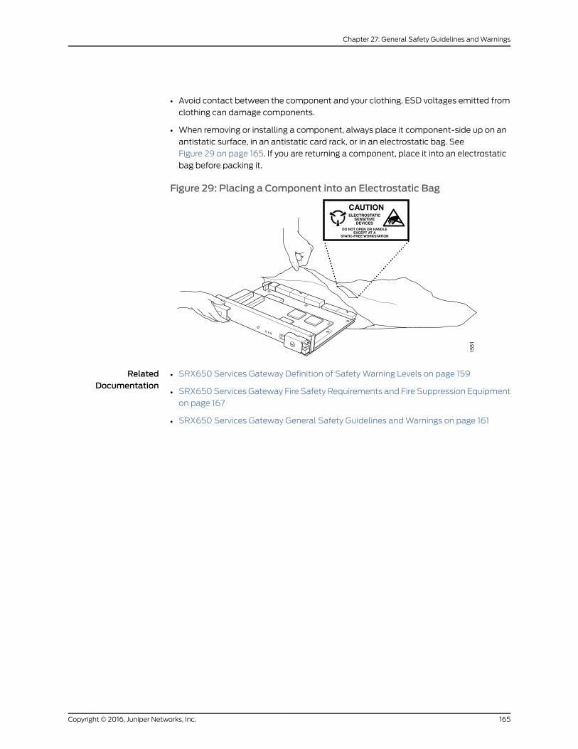
• Avoid contact between the component and your clothing. ESD voltages emitted from
clothing can damage components.
• When removing or installing a component, always place it component-side up on an
antistatic surface, in an antistatic card rack, or in an electrostatic bag. See
Figure 29 on page 165. If you are returning a component, place it into an electrostatic
bag before packing it.
Figure 29: Placing a Component into an Electrostatic Bag
RelatedDocumentation
• SRX650 Services Gateway Definition of Safety Warning Levels on page 159
• SRX650 Services Gateway Fire Safety Requirements and Fire Suppression Equipment
on page 167
• SRX650 Services Gateway General Safety Guidelines and Warnings on page 161
165Copyright © 2016, Juniper Networks, Inc.
Chapter 27: General Safety Guidelines and Warnings

Copyright © 2016, Juniper Networks, Inc.166
SRX650 Services Gateway Hardware Guide

CHAPTER 28
Fire Safety Requirements
• SRX650 Services Gateway Fire Safety Requirements and Fire Suppression
Equipment on page 167
SRX650ServicesGatewayFireSafetyRequirements andFireSuppressionEquipment
In the event of a fire emergency involving devices and other network equipment, the
safety of people is the primary concern. Establish procedures for protecting people in
the event of a fire emergency, provide safety training, and properly provision fire control
equipment and fire extinguishers.
In addition, establish procedures to protect your equipment in the event of a fire
emergency. Juniper Networks products should be installed in an environment suitable
for electronic equipment. We recommend that fire suppression equipment be available
in the event of a fire in the vicinity of the equipment and that all local fire, safety, and
electrical codes and ordinances be observed when installing and operating your
equipment.
In the event of an electrical hazard or an electrical fire, first turn power off to the equipment
at the source. Then use a Type C fire extinguisher to extinguish the fire. Type C fire
extinguishers, which use noncorrosive fire retardants such as carbon dioxide (CO2) and
Halotron, are most effective for suppressing electrical fires. Type C fire extinguishers
displace the oxygen from the point of combustion to eliminate the fire. For extinguishing
fire on or around equipment that draws air from the environment for cooling, use this
type of inert oxygen displacement extinguisher instead of an extinguisher that leave
residues on equipment.
Do not use multipurpose Type ABC chemical fire extinguishers (dry chemical fire
extinguishers) near Juniper Networks equipment. The primary ingredient in these fire
extinguishers is monoammonium phosphate, which is very sticky and difficult to clean.
In addition, in minute amounts of moisture, monoammonium phosphate can become
highly corrosive and corrodes most metals.
Any equipment in a room in which a chemical fire extinguisher has been discharged is
subject to premature failure and unreliable operation. The equipment is considered to
be irreparably damaged.
167Copyright © 2016, Juniper Networks, Inc.
NOTE: Tokeepwarrantieseffective,donotuseadrychemical fireextinguisherto control a fire at or near a Juniper Networks services gateway. If a drychemical fire extinguisher is used, the unit is no longer eligible for coverageunder a service agreement.
We recommend that you dispose of any irreparably damaged equipment in an
environmentally responsible manner.
RelatedDocumentation
• SRX650 Services Gateway Definition of Safety Warning Levels on page 159
• Preventing Electrostatic Discharge Damage to the SRX650 Services Gateway on
page 164
• SRX650 Services Gateway General Safety Guidelines and Warnings on page 161
Copyright © 2016, Juniper Networks, Inc.168
SRX650 Services Gateway Hardware Guide

CHAPTER 29
Laser and LED Safety Guidelines andWarnings
• General Laser Safety Guidelines on page 169
• Class 1 Laser Warning on page 170
• Class 1 LED Product Warning on page 170
• Laser Beam Warning on page 171
• Radiation from Open Port Apertures Warning on page 172
General Laser Safety Guidelines
When working around the services gateway, observe the following safety guidelines to
prevent eye injury:
• Do not look into unterminated ports or at fibers that connect to unknown sources.
• Do not examine unterminated optical ports with optical instruments.
• Avoid direct exposure to the beam.
WARNING: Unterminated optical connectors can emit invisible laserradiation. The lens in the human eye focuses all the laser power on theretina, so focusing the eye directly on a laser source—even a low-powerlaser—could permanently damage the eye.
RelatedDocumentation
SRX650 Services Gateway General Safety Guidelines and Warnings on page 161•
• Class 1 Laser Warning on page 170
• Class 1 LED Product Warning on page 170
• Laser Beam Warning on page 171
• Radiation from Open Port Apertures Warning on page 172
169Copyright © 2016, Juniper Networks, Inc.

Class 1 LaserWarning
WARNING: Class 1 laser product.
Waarschuwing Klasse-1 laser produkt.
Varoitus Luokan 1 lasertuote.
Attention Produit laser de classe I.
Warnung Laserprodukt der Klasse 1.
Avvertenza Prodotto laser di Classe 1.
Advarsel Laserprodukt av klasse 1.
Aviso Produto laser de classe 1.
¡Atención! Producto láser Clase I.
Varning! Laserprodukt av klass 1.
RelatedDocumentation
SRX650 Services Gateway General Safety Guidelines and Warnings on page 161•
• General Laser Safety Guidelines on page 169
• Class 1 LED Product Warning on page 170
• Laser Beam Warning on page 171
• Radiation from Open Port Apertures Warning on page 172
Class 1 LED ProductWarning
WARNING: Class 1 LED product.
Waarschuwing Klasse 1 LED-product.
Varoitus Luokan 1 valodiodituote.
Attention Alarme de produit LED Class I.
Warnung Class 1 LED-Produktwarnung.
Avvertenza Avvertenza prodotto LED di Classe 1.
Advarsel LED-produkt i klasse 1.
Aviso Produto de classe 1 com LED.
¡Atención! Aviso sobre producto LED de Clase 1.
Copyright © 2016, Juniper Networks, Inc.170
SRX650 Services Gateway Hardware Guide
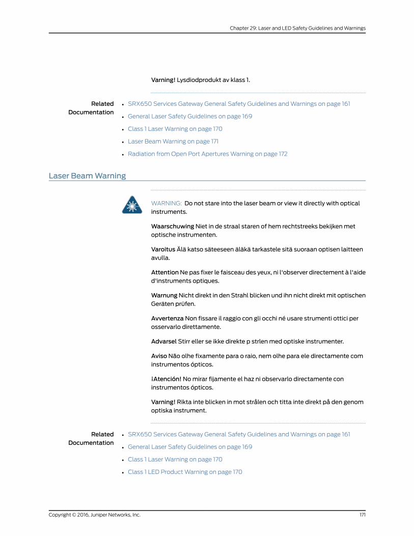
Varning! Lysdiodprodukt av klass 1.
RelatedDocumentation
SRX650 Services Gateway General Safety Guidelines and Warnings on page 161•
• General Laser Safety Guidelines on page 169
• Class 1 Laser Warning on page 170
• Laser Beam Warning on page 171
• Radiation from Open Port Apertures Warning on page 172
Laser BeamWarning
WARNING: Do not stare into the laser beam or view it directly with opticalinstruments.
WaarschuwingNiet in de straal staren of hem rechtstreeks bekijkenmetoptische instrumenten.
Varoitus Älä katso säteeseen äläkä tarkastele sitä suoraan optisen laitteenavulla.
AttentionNe pas fixer le faisceau des yeux, ni l'observer directement à l'aided'instruments optiques.
WarnungNicht direkt in den Strahl blicken und ihn nicht direktmit optischenGeräten prüfen.
AvvertenzaNon fissare il raggio con gli occhi né usare strumenti ottici perosservarlo direttamente.
Advarsel Stirr eller se ikke direkte p strlenmed optiske instrumenter.
AvisoNão olhe fixamente para o raio, nem olhe para ele directamente cominstrumentos ópticos.
¡Atención!Nomirar fijamente el haz ni observarlo directamente coninstrumentos ópticos.
Varning! Rikta inte blicken in mot strålen och titta inte direkt på den genomoptiska instrument.
RelatedDocumentation
SRX650 Services Gateway General Safety Guidelines and Warnings on page 161•
• General Laser Safety Guidelines on page 169
• Class 1 Laser Warning on page 170
• Class 1 LED Product Warning on page 170
171Copyright © 2016, Juniper Networks, Inc.
Chapter 29: Laser and LED Safety Guidelines and Warnings
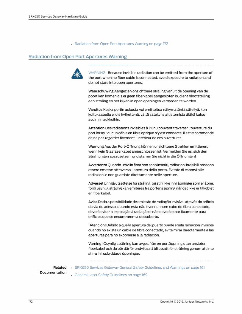
• Radiation from Open Port Apertures Warning on page 172
Radiation fromOpen Port AperturesWarning
WARNING: Because invisible radiation can be emitted from the aperture ofthe port when no fiber cable is connected, avoid exposure to radiation anddo not stare into open apertures.
Waarschuwing Aangezien onzichtbare straling vanuit de opening van depoort kan komen als er geen fiberkabel aangesloten is, dient blootstellingaan straling en het kijken in open openingen vermeden te worden.
Varoitus Koska portin aukosta voi emittoitua näkymätöntä säteilyä, kunkuitukaapelia ei ole kytkettynä, vältä säteilylle altistumista äläkä katsoavoimiin aukkoihin.
Attention Des radiations invisibles à l'il nu pouvant traverser l'ouverture duport lorsqu'aucun câble en fibre optique n'y est connecté, il est recommandéde ne pas regarder fixement l'intérieur de ces ouvertures.
Warnung Aus der Port-Öffnung können unsichtbare Strahlen emittieren,wenn kein Glasfaserkabel angeschlossen ist. Vermeiden Sie es, sich denStrahlungen auszusetzen, und starren Sie nicht in die Öffnungen!
AvvertenzaQuando i cavi in fibranonsono inseriti, radiazioni invisibili possonoessere emesse attraverso l'apertura della porta. Evitate di esporvi alleradiazioni e non guardate direttamente nelle aperture.
AdvarselUnngåutsettelse for stråling, ogstirr ikke inn i åpninger someråpne,fordi usynlig stråling kan emiteres fra portens åpning når det ikke er tilkobleten fiberkabel.
AvisoDadaapossibilidadedeemissãode radiação invisível atravésdoorifícioda via de acesso, quando esta não tiver nenhum cabo de fibra conectado,deverá evitar a exposição à radiação e não deverá olhar fixamente paraorifícios que se encontrarem a descoberto.
¡Atención!Debidoaque laaperturadelpuertopuedeemitir radiación invisiblecuando no existe un cable de fibra conectado, evitemirar directamente a lasaperturas para no exponerse a la radiación.
Varning!Osynlig strålning kan avges från en portöppning utan anslutenfiberkabel ochdubör därför undvika att bli utsatt för strålning genomatt intestirra in i oskyddade öppningar.
RelatedDocumentation
• SRX650 Services Gateway General Safety Guidelines and Warnings on page 161
• General Laser Safety Guidelines on page 169
Copyright © 2016, Juniper Networks, Inc.172
SRX650 Services Gateway Hardware Guide

• Class 1 Laser Warning on page 170
• Class 1 LED Product Warning on page 170
• Laser Beam Warning on page 171
173Copyright © 2016, Juniper Networks, Inc.
Chapter 29: Laser and LED Safety Guidelines and Warnings

Copyright © 2016, Juniper Networks, Inc.174
SRX650 Services Gateway Hardware Guide

CHAPTER 30
Maintenance and Operational SafetyGuidelines andWarnings
• Battery-Handling Warning on page 175
• Lightning Activity Warning on page 176
• Jewelry Removal Warning on page 177
• Operating Temperature Warning on page 179
• Product Disposal Warning on page 180
• Lithium Battery on page 181
Battery-HandlingWarning
WARNING: Replacing the battery incorrectly might result in an explosion.Replace the battery only with the same or equivalent type recommended bythemanufacturer. Disposeof usedbatteries according to themanufacturer'sinstructions.
Waarschuwing Er is ontploffingsgevaar als de batterij verkeerd vervangenwordt. Vervang de batterij slechts met hetzelfde of een equivalent type datdoor de fabrikant aanbevolen is. Gebruikte batterijendienenovereenkomstigfabrieksvoorschriften weggeworpen te worden.
Varoitus Räjähdyksen vaara, jos akku on vaihdettu väärään akkuun. Käytävaihtamiseen ainoastaan saman- tai vastaavantyyppistä akkua, joka onvalmistajansuosittelema.Hävitäkäytetytakutvalmistajanohjeidenmukaan.
Attention Danger d'explosion si la pile n'est pas remplacée correctement.Ne la remplacer que par une pile de type semblable ou équivalent,recommandée par le fabricant. Jeter les piles usagées conformément auxinstructions du fabricant.
Warnung Bei Einsetzen einer falschen Batterie besteht Explosionsgefahr.Ersetzen Sie die Batterie nur durch den gleichen oder vomHerstellerempfohlenen Batterietyp. Entsorgen Sie die benutzten Batterien nach denAnweisungen des Herstellers.
175Copyright © 2016, Juniper Networks, Inc.

Avvertenza Pericolo di esplosione se la batteria non è installatacorrettamente.Sostituiresoloconunadi tipougualeoequivalente, consigliatadalproduttore. Eliminare lebatterieusatesecondo le istruzionidelproduttore.
Advarsel Det kan være fare for eksplosjon hvis batteriet skiftes på feil måte.Skift kunmed sammeeller tilsvarende type somer anbefalt av produsenten.Kasser brukte batterier i henhold til produsentens instruksjoner.
AvisoExiste perigo de explosão se a bateria for substituída incorrectamente.Substitua a bateria por uma bateria igual ou de um tipo equivalenterecomendado pelo fabricante. Destrua as baterias usadas conforme asinstruções do fabricante.
¡Atención! Existe peligro de explosión si la batería se reemplaza demaneraincorrecta. Reemplazar la batería exclusivamente con el mismo tipo o elequivalente recomendado por el fabricante. Desechar las baterías gastadassegún las instrucciones del fabricante.
Varning!Explosionsfara vid felaktigt batteribyte. Ersätt endast batterietmedsamma batterityp som rekommenderas av tillverkaren eller motsvarande.Följ tillverkarens anvisningar vid kassering av använda batterier.
RelatedDocumentation
SRX650 Services Gateway General Safety Guidelines and Warnings on page 161•
• Jewelry Removal Warning on page 177
• Lightning Activity Warning on page 176
• Operating Temperature Warning on page 179
• Product Disposal Warning on page 180
Lightning ActivityWarning
WARNING: Donotworkon thesystemorconnectordisconnectcablesduringperiods of lightning activity.
Waarschuwing Tijdens onweer dat gepaard gaat met bliksem, dient u nietaan het systeem te werken of kabels aan te sluiten of te ontkoppelen.
Varoitus Älä työskentele järjestelmän parissa äläkä yhdistä tai irrotakaapeleita ukkosilmalla.
AttentionNe pas travailler sur le système ni brancher ou débrancher lescâbles pendant un orage.
Warnung Arbeiten Sie nicht am System und schließen Sie keine Kabel anbzw. trennen Sie keine ab, wenn es gewittert.
Copyright © 2016, Juniper Networks, Inc.176
SRX650 Services Gateway Hardware Guide
AvvertenzaNon lavorare sul sistema o collegare oppure scollegare i cavidurante un temporale con fulmini.
AdvarselUtfør aldri arbeidpåsystemet, eller koble kabler til eller fra systemetnår det tordner eller lyner.
AvisoNão trabalhe no sistema ou ligue e desligue cabos durante períodosdemau tempo (trovoada).
¡Atención!No operar el sistema ni conectar o desconectar cables durante eltranscurso de descargas eléctricas en la atmósfera.
Varning!Vid åska skall du aldrig utföra arbete på systemet eller ansluta ellerkoppla loss kablar.
RelatedDocumentation
SRX650 Services Gateway General Safety Guidelines and Warnings on page 161•
• Battery-Handling Warning on page 175
• Jewelry Removal Warning on page 177
• Operating Temperature Warning on page 179
• Product Disposal Warning on page 180
Jewelry RemovalWarning
WARNING: Before working on equipment that is connected to power lines,remove jewelry, including rings, necklaces, and watches. Metal objects heatup when connected to power and ground and can cause serious burns orweld themetal object to the terminals.
Waarschuwing Alvorens aan apparatuur te werken die met elektrischeleidingen is verbonden, sieraden (inclusief ringen, kettingen en horloges)verwijderen. Metalen voorwerpen worden warmwanneer zemet stroom enaarde zijn verbonden, en kunnen ernstige brandwonden veroorzaken of hetmetalen voorwerp aan de aansluitklemmen lassen.
Varoitus Ennen kuin työskentelet voimavirtajohtoihin kytkettyjen laitteidenparissa, otapois kaikki korut (sormukset, kaulakorut ja kellotmukaan lukien).Metalliesineet kuumenevat, kun ne ovat yhteydessä sähkövirran ja maankanssa, janevoivataiheuttaavakaviapalovammoja tai hitsatametalliesineetkiinni liitäntänapoihin.
AttentionAvantd'accéderàcetéquipementconnectéaux lignesélectriques,ôter toutbijou(anneaux,colliersetmontrescompris). Lorsqu'ilssontbranchésà l'alimentation et reliés à la terre, les objets métalliques chauffent, ce quipeutprovoquerdesblessuresgravesousouder l'objetmétalliqueauxbornes.
177Copyright © 2016, Juniper Networks, Inc.
Chapter 30: Maintenance and Operational Safety Guidelines and Warnings

Warnung Vor der Arbeit an Geräten, die an das Netz angeschlossen sind,jeglichen Schmuck (einschließlich Ringe, Ketten und Uhren) abnehmen.Metallgegenstände erhitzen sich, wenn sie an das Netz und die Erdeangeschlossen werden, und können schwere Verbrennungen verursachenoder an die Anschlußklemmen angeschweißt werden.
Avvertenza Prima di intervenire su apparecchiature collegate alle linee dialimentazione, togliersi qualsiasi monile (inclusi anelli, collane, braccialettied orologi). Gli oggetti metallici si riscaldano quando sono collegati tra puntidi alimentazione emassa: possono causare ustioni gravi oppure il metallopuò saldarsi ai terminali.
Advarsel Fjern alle smykker (inkludert ringer, halskjeder og klokker) før duskal arbeidepåutstyr somer koblet til kraftledninger.Metallgjenstander somer koblet til kraftledninger og jord blir svært varme og kan forårsake alvorligebrannskader eller smelte fast til polene.
Aviso Antes de trabalhar em equipamento que esteja ligado a linhas decorrente, retire todas as jóias que estiver a usar (incluindo anéis, fios erelógios). Os objectosmetálicos aquecerão em contacto com a corrente eem contacto com a ligação à terra, podendo causar queimaduras graves ouficarem soldados aos terminais.
¡Atención! Antes de operar sobre equipos conectados a líneas dealimentación, quitarse las joyas (incluidos anillos, collares y relojes). Losobjetosdemetal secalientancuandoseconectana laalimentaciónyatierra,lo que puede ocasionar quemaduras graves o que los objetosmetálicosqueden soldados a los bornes.
Varning! Tag av alla smycken (inklusive ringar, halsband och armbandsur)innanduarbetarpåutrustningsomärkopplad till kraftledningar.Metallobjekthettas upp när de kopplas ihopmed ström och jord och kan förorsakaallvarliga brännskador; metallobjekt kan också sammansvetsasmedkontakterna.
RelatedDocumentation
SRX650 Services Gateway General Safety Guidelines and Warnings on page 161•
• Battery-Handling Warning on page 175
• Lightning Activity Warning on page 176
• Operating Temperature Warning on page 179
• Product Disposal Warning on page 180
Copyright © 2016, Juniper Networks, Inc.178
SRX650 Services Gateway Hardware Guide
Operating TemperatureWarning
WARNING: Toprevent theservicesgateway fromoverheating,donotoperateit in anarea that exceeds themaximumrecommendedambient temperatureof 104οF (40οC). To prevent airflow restriction, allow at least 6 in. (15.2 cm)
of clearance around the ventilation openings.
WaarschuwingOmte voorkomendatwelke services gateway van de JuniperNetworks services gateway dan ook oververhit raakt, dient u deze niet tebedienen op een plaats waar demaximale aanbevolenomgevingstemperatuur van 40οCwordt overschreden. Om te voorkomen
dat de luchtstroomwordt beperkt, dient erminstens 15,2 cm speling rond deventilatie-openingen te zijn.
VaroitusEttei JuniperNetworksservicesgateway-sarjan reititinylikuumentuisi,sitä ei saa käyttää tilassa, jonka lämpötila ylittää korkeimman suositellunympäristölämpötilan 40οC. Ettei ilmanvaihto estyisi, tuuletusaukkojen
ympärille on jätettävä ainakin 15,2 cm tilaa.
Attention Pour éviter toute surchauffe des routeurs de la gamme JuniperNetworks services gateway, ne l'utilisez pasdansune zoneoù la températureambianteestsupérieureà40οC.Pourpermettreunflotd'air constant,dégagez
un espace d'aumoins 15,2 cm autour des ouvertures de ventilations.
WarnungUm einen services gateway der services gateway vor Überhitzungzu schützen, darf dieser nicht in einer Gegend betrieben werden, in der dieUmgebungstemperatur das empfohlene Maximum von 40οC überschreitet.
UmLüftungsverschlußzuverhindern, achtenSiedarauf, daßmindestens 15,2cm lichter Raum um die Lüftungsöffnungen herum frei bleibt.
Avvertenza Per evitare il surriscaldamento dei services gateway, nonadoperateli in un locale che ecceda la temperatura ambientale massima di40οC.Perevitareche lacircolazionedell'aria sia impedita, lasciateunospazio
di almeno 15.2 cm di fronte alle aperture delle ventole.
AdvarselUnngå overoppheting av eventuelle rutere i Juniper Networksservices gateway Disse skal ikke brukes på steder der den anbefaltemaksimale omgivelsestemperaturen overstiger 40οC. Sørg for at klaringen
rundt lufteåpningene erminst 15,2 cm for å forhindre nedsatt luftsirkulasjon.
Aviso Para evitar o sobreaquecimento do encaminhador Juniper Networksservices gateway, não utilize este equipamento numa área que exceda atemperaturamáxima recomendada de 40οC. Para evitar a restrição à
circulaçãodear, deixepelomenosumespaçode 15,2cmàvoltadasaberturasde ventilação.
¡Atención! Para impedir que un encaminador de la serie Juniper Networksservices gateway se recaliente, no lo haga funcionar en un área en la que se
179Copyright © 2016, Juniper Networks, Inc.
Chapter 30: Maintenance and Operational Safety Guidelines and Warnings
supere la temperaturaambientemáximarecomendadade40οC.Para impedir
la restricción de la entrada de aire, deje un espacio mínimo de 15,2 cmalrededor de las aperturas para ventilación.
Varning! Förhindra att en Juniper Networks services gateway överhettasgenomatt inteanvändaden iettområdedärdenmaximalt rekommenderadeomgivningstemperaturen på 40οC överskrids. Förhindra att luftcirkulationen
inskränksgenomattse till attdet finns fritt utrymmepåminst 15,2cmomkringventilationsöppningarna.
RelatedDocumentation
SRX650 Services Gateway General Safety Guidelines and Warnings on page 161•
• Battery-Handling Warning on page 175
• Lightning Activity Warning on page 176
• Jewelry Removal Warning on page 177
• Product Disposal Warning on page 180
Product DisposalWarning
WARNING: Disposalof thisproductmustbehandledaccording toall nationallaws and regulations.
Waarschuwing Dit produkt dient volgens alle landelijke wetten envoorschriften te worden afgedankt.
VaroitusTämän tuotteen lopullisesta hävittämisestä tulee huolehtia kaikkiavaltakunnallisia lakeja ja säännöksiä noudattaen.
Attention Lamise au rebut définitive de ce produit doit être effectuéeconformément à toutes les lois et réglementations en vigueur.
Warnung Dieses Produkt muß den geltenden Gesetzen und Vorschriftenentsprechend entsorgt werden.
Avvertenza L'eliminazione finale di questo prodotto deve essere eseguitaosservando le normative italiane vigenti in materia
AdvarselEndeligdisponeringavdetteproduktetmåskje ihenholdtil nasjonalelover og forskrifter.
Aviso A descartagem final deste produto deverá ser efectuada de acordocom os regulamentos e a legislação nacional.
¡Atención! El desecho final de este producto debe realizarse según todas lasleyes y regulaciones nacionales
Copyright © 2016, Juniper Networks, Inc.180
SRX650 Services Gateway Hardware Guide

Varning!Slutlig kasseringavdennaproduktbör skötas i enlighetmed landetsalla lagar och föreskrifter.
RelatedDocumentation
SRX650 Services Gateway General Safety Guidelines and Warnings on page 161•
• Battery-Handling Warning on page 175
• Lightning Activity Warning on page 176
• Jewelry Removal Warning on page 177
• Operating Temperature Warning on page 179
Lithium Battery
Batteries in this product are not based on mercury, lead, or cadmium substances. The
batteries used in this product are in compliance with EU Directives 91/157/EEC, 93/86/EEC,
and 98/101/EEC. The product documentation includes instructional information about
the proper method of reclamation and recycling.
RelatedDocumentation
• SRX650 Services Gateway General Safety Guidelines and Warnings on page 161
• SRX650 Services Gateway Acoustic Noise Compliance Statements on page 194
181Copyright © 2016, Juniper Networks, Inc.
Chapter 30: Maintenance and Operational Safety Guidelines and Warnings

Copyright © 2016, Juniper Networks, Inc.182
SRX650 Services Gateway Hardware Guide

CHAPTER 31
Electrical SafetyGuidelines andWarnings
• In Case of Electrical Accident on page 183
• General Electrical Safety Guidelines and Warnings on page 183
• AC Power Electrical Safety Guidelines on page 184
• DC Power Electrical Safety Guidelines on page 185
In Case of Electrical Accident
If an electrical accident results in an injury, take the following actions in this order:
1. Use caution. Be aware of potentially hazardous conditions that could cause further
injury.
2. Disconnect power from the services gateway.
3. If possible, send another person to get medical aid. Otherwise, assess the condition
of the victim, then call for help.
RelatedDocumentation
SRX650 Services Gateway General Safety Guidelines and Warnings on page 161•
• General Electrical Safety Guidelines and Warnings on page 183
• AC Power Electrical Safety Guidelines on page 184
• SRX650 Services Gateway Power Requirements on page 60
• Grounding the SRX650 Services Gateway on page 82
General Electrical Safety Guidelines andWarnings
• Install the services gateway in compliance with the following local, national, or
international electrical codes:
• United States—National Fire Protection Association (NFPA 70), United States
National Electrical Code
• Canada—Canadian Electrical Code, Part 1, CSA C22.1
183Copyright © 2016, Juniper Networks, Inc.

• Other countries—International Electromechanical Commission (IEC) 60364, Part 1
through Part 7
• Evaluated to the TN power system
• Locate the emergency power-off switch for the room in which you are working so that
if an electrical accident occurs, you can quickly turn off the power.
• Do not work alone if potentially hazardous conditions exist anywhere in your workspace.
• Never assume that power is disconnected from a circuit. Always check the circuit before
starting to work.
• Carefully look for possible hazards in your work area, such as moist floors, ungrounded
power extension cords, and missing safety grounds.
• Operate the services gateway within marked electrical ratings and product usage
instructions.
• For the services gateway and peripheral equipment to function safely and correctly,
use the cables and connectors specified for the attached peripheral equipment, and
make certain they are in good condition.
RelatedDocumentation
SRX650 Services Gateway General Safety Guidelines and Warnings on page 161•
• In Case of Electrical Accident on page 183
• AC Power Electrical Safety Guidelines on page 184
• DC Power Electrical Safety Guidelines on page 185
• SRX650 Services Gateway Power Requirements on page 60
• Grounding the SRX650 Services Gateway on page 82
AC Power Electrical Safety Guidelines
CAUTION: For services gateways with AC power supplies, an external surgeprotective device (SPD)must be used at the AC power source.
The following electrical safety guidelines apply to AC-powered services gateways:
• AC-powered services gateways are shipped with a three-wire electrical cord with a
grounding-type plug that fits only a grounding-type power outlet. Do not circumvent
this safety feature. Equipment grounding should comply with local and national
electrical codes.
• You must provide an external certified circuit breaker rated minimum 15 A in the building
installation.
• The power cord serves as the main disconnecting device. The socket outlet must be
near the switch and be easily accessible.
Copyright © 2016, Juniper Networks, Inc.184
SRX650 Services Gateway Hardware Guide
• When a services gateway is equipped with multiple AC power supplies, all power cords
(one for each power supply) must be unplugged to completely disconnect power to
the switch.
• Note the following warnings printed on the label next to the power supplies:
“CAUTION: THIS UNIT HAS MORE THAN ONE POWER SUPPLY CORD. DISCONNECT
ALL POWER SUPPLY CORDS BEFORE SERVICING TO AVOID ELECTRIC SHOCK.”
“ATTENTION: CET APPAREIL COMPORTE PLUS D'UN CORDON D'ALIMENTATION.
AFIN DE PRÉVENIR LES CHOCS ÉLECTRIQUES, DÉBRANCHER TOUT CORDON
D'ALIMENTATION AVANT DE FAIRE LE DÉPANNAGE.”
Power Cable Warning (Japanese)
The preceding translates as follows:
WARNING: The attached power cable is only for this product. Do not use thecable for another product.
RelatedDocumentation
SRX650 Services Gateway General Safety Guidelines and Warnings on page 161•
• In Case of Electrical Accident on page 183
• General Electrical Safety Guidelines and Warnings on page 183
• SRX650 Services Gateway Power Requirements on page 60
• Grounding the SRX650 Services Gateway on page 82
DC Power Electrical Safety Guidelines
When working with DC-powered equipment, observe the following guidelines and
warnings:
• DC Power Electrical Safety Guidelines
• DC Power Disconnection Warning
• DC Power Grounding Requirements and Warning
• DC Power Wiring Sequence Warning
• DC Power Wiring Terminations Warning
DC Power Electrical Safety Guidelines
185Copyright © 2016, Juniper Networks, Inc.
Chapter 31: Electrical Safety Guidelines and Warnings

The following electrical safety guidelines apply to a DC-powered services gateway:
• A DC-powered services gateway is equipped with a DC terminal block that is rated for
the power requirements of a maximally configured services gateway. To supply
sufficient power, terminate the DC input wiring on a facility DC source capable of
supplying at least 65 A @ –48 VDC for the system, or at least 48 A @ –48 VDC for
each power supply. We recommend that the 48 VDC facility DC source be equipped
with a circuit breaker rated at 60 A (–48 VDC) minimum, or as required by local code.
Incorporate an easily accessible disconnect device into the facility wiring. In the United
States and Canada, the –48 VDC facility should be equipped with a circuit breaker
rated a minimum of 125% of the power provisioned for the input in accordance with
the National Electrical Code in the US and the Canadian Electrical Code in Canada. Be
sure to connect the ground wire or conduit to a solid office (earth) ground. A closed
loop ring is recommended for terminating the ground conductor at the ground stud.
• Run two wires from the circuit breaker box to a source of 48 VDC. Use appropriate
gauge wire to handle up to 60 A.
• A DC-powered services gateway that is equipped with a DC terminal block is intended
only for installation in a restricted access location. In the United States, a restricted
access area is one in accordance with Articles 110-16, 110-17, and 110-18 of the National
Electrical Code ANSI/NFPA 70.
NOTE: Primary overcurrent protection is provided by the building circuitbreaker. This breaker should protect against excess currents, short circuits,and earth faults in accordance with NEC ANSI/NFPA70.
• Ensure that the polarity of the DC input wiring is correct. Under certain conditions,
connections with reversed polarity might trip the primary circuit breaker or damage
the equipment.
• For personal safety, connect the green and yellow wire to safety (earth) ground at both
the services gateway and the supply side of the DC wiring.
• The marked input voltage of –48 VDC for a DC-powered services gateway is the nominal
voltage associated with the battery circuit, and any higher voltages are only to be
associated with float voltages for the charging function.
• Because the services gateway is a positive ground system, you must connect the
positive lead to the terminal labeledRETURN, the negative lead to the terminal labeled
–48V, and the earth ground to the chassis grounding points.
DC Power DisconnectionWarning
WARNING: Before performing any of the following procedures, ensure thatpower is removed from the DC circuit. To ensure that all power is off, locatethe circuit breaker on the panel board that services the DC circuit, switch thecircuit breaker to theoffposition (O), and tape theswitchhandleof thecircuit
breaker in the off position (O).
Copyright © 2016, Juniper Networks, Inc.186
SRX650 Services Gateway Hardware Guide

Waarschuwing Voordat u een van de onderstaande procedures uitvoert,dientu tecontrolerenofdestroomnaarhetgelijkstroomcircuit uitgeschakeldis. Om u ervan te verzekeren dat alle stroomUIT is geschakeld, kiest u op hetschakelbord de stroomverbreker die het gelijkstroom circuit bedient, draaitde stroomverbreker naar de UIT positie en plakt de schakelaarhendel van destroomverbreker met plakband in de UIT positie vast.
Varoitus Varmista, että tasavirtapiirissä ei ole virtaa ennen seuraavientoimenpiteiden suorittamista. Varmistaaksesi, että virta on KATKAISTUtäysin,paikannatasavirrastahuolehtivassakojetaulussasijaitsevasuojakytkin,käännä suojakytkin KATKAISTU-asentoon ja teippaa suojakytkimen varsiniin, että se pysyy KATKAISTU-asennossa.
Attention Avant de pratiquer l'une quelconque des procédures ci-dessous,vérifier que le circuit en courant continu n'est plus sous tension. Pour en êtresûr, localiser ledisjoncteur situésur lepanneaudeserviceducircuit encourantcontinu, placer le disjoncteur enposition fermée (OFF) et, à l'aide d'un rubanadhésif, bloquer la poignée du disjoncteur en position OFF.
Warnung Vor Ausführung der folgenden Vorgänge ist sicherzustellen, daßdie Gleichstromschaltung keinen Strom erhält. Um sicherzustellen, daßsämtlicher Strom abgestellt ist, machen Sie auf der Schalttafel denUnterbrecher für die Gleichstromschaltung ausfindig, stellen Sie denUnterbrecher auf AUS, und kleben Sie den Schaltergriff des Unterbrechersmit Klebeband in der AUS-Stellung fest.
AvvertenzaPrimadi svolgereunaqualsiasidelleprocedureseguenti, verificareche il circuito CC non sia alimentato. Per verificare che tutta l'alimentazionesia scollegata (OFF), individuare l'interruttore automatico sul quadrostrumenti che alimenta il circuito CC, mettere l'interruttore in posizione OFFe fissarlo con nastro adesivo in tale posizione.
Advarsel Før noen av disse prosedyrene utføres, kontroller at strømmen erfrakoblet likestrømkretsen. Sørg for at all strøm er slått AV. Dette gjøres vedå lokalisere strømbryteren på brytertavlen som betjener likestrømkretsen,slå strømbryterenAVog teipebryterhåndtaketpåstrømbryteren iAV-stilling.
AvisoAntes de executar umdos seguintes procedimentos, certifique-se quedesligou a fonte de alimentação de energia do circuito de corrente contínua.Para se assegurar que toda a corrente foi DESLIGADA, localize o disjuntor nopainel que serve o circuito de corrente contínua e coloque-o na posição OFF(Desligado), segurandonessaposiçãoamanivelado interruptor dodisjuntorcom fita isoladora.
¡Atención! Antes de proceder con los siguientes pasos, comprobar que laalimentacióndelcircuitodecorrientecontinua(CC)estécortada(OFF).Paraasegurarse de que toda la alimentación esté cortada (OFF), localizar elinterruptor automático en el panel que alimenta al circuito de corrientecontinua, cambiar el interruptor automático a la posicióndeApagado (OFF),
187Copyright © 2016, Juniper Networks, Inc.
Chapter 31: Electrical Safety Guidelines and Warnings
y sujetar con cinta la palanca del interruptor automático en posición deApagado (OFF).
Varning! Innan du utför någon av följande procedurer måste du kontrolleraatt strömförsörjningen till likströmskretsen är bruten. Kontrollera att allströmförsörjning är BRUTEN genomatt slå AV det överspänningsskydd somskyddar likströmskretsen och tejpa fast överspänningsskyddets omkopplarei FRÅN-läget.
DC Power Grounding Requirements andWarning
An insulated grounding conductor that is identical in size to the grounded and ungrounded
branch circuit supply conductors, but that is identifiable by green and yellow stripes, is
installed as part of the branch circuit that supplies the unit. The grounding conductor is
a separately derived system at the supply transformer or motor generator set.
WARNING: When you install the services gateway, youmust alwaysmakethe ground connection first and disconnect it last.
WaarschuwingBij de installatie vanhet toestelmoetdeaardverbindingaltijdhet eerste worden gemaakt en het laatste worden losgemaakt.
Varoitus Laitetta asennettaessa onmaahan yhdistäminen aina tehtäväensiksi ja maadoituksen irti kytkeminen viimeiseksi.
Attention Lors de l'installation de l'appareil, la mise à la terre doit toujoursêtre connectée en premier et déconnectée en dernier.
Warnung Der Erdanschlußmuß bei der Installation der Einheit immer zuersthergestellt und zuletzt abgetrennt werden.
Avvertenza In fase di installazione dell'unità, eseguire sempre per primo ilcollegamento amassa e disconnetterlo per ultimo.
AdvarselNår enheten installeres, må jordledningen alltid tilkobles først ogfrakobles sist.
Aviso Ao instalar a unidade, a ligação à terra deverá ser sempre a primeira aser ligada, e a última a ser desligada.
¡Atención!Al instalar el equipo, conectar la tierra la primera y desconectarlala última.
Varning!Vid installationavenhetenmåste jordledningenalltid anslutas förstoch kopplas bort sist.
DC PowerWiring SequenceWarning
Copyright © 2016, Juniper Networks, Inc.188
SRX650 Services Gateway Hardware Guide

WARNING: Wire the DC power supply using the appropriate lugs. Whenconnecting power, the proper wiring sequence is ground to ground, +RTN to+RTN, then –48 V to –48 V.When disconnecting power, the proper wiringsequence is –48 V to –48 V, +RTN to +RTN, then ground to ground. Notethat thegroundwire shouldalwaysbe connected first anddisconnected last.
WaarschuwingDe juiste bedradingsvolgorde verbonden is aarde naar aarde,+RTN naar +RTN, en –48 V naar – 48 V. De juiste bedradingsvolgordelosgemaakt is en –48 V naar – 48 V, +RTN naar +RTN, aarde naar aarde.
VaroitusOikea yhdistettava kytkentajarjestys onmaajohtomaajohtoon,+RTN varten +RTN, –48 V varten – 48 V. Oikea irrotettava kytkentajarjestyson –48 V varten – 48 V, +RTN varten +RTN, maajohtomaajohtoon.
Attention Câblez l'approvisionnement d'alimentation CC En utilisant lescrochets appropriés à l'extrémité de câblage. En reliant la puissance, l'ordreapproprié de câblage est rectifié pour rectifier, +RTN à +RTN, puis –48 V à–48 V. En débranchant la puissance, l'ordre approprié de câblage est –48 Và–48V, +RTNà+RTN, a alors rectifié pour rectifier. Notez que le fil demassedevrait toujours être relié d'abord et débranché pour la dernière fois. Notezque le fil demasse devrait toujours être relié d'abord et débranché pour ladernière fois.
WarnungDieStromzufuhr ist nurmit geeignetenRingösenandasDCNetzteilanzuschliessen. Die richtige Anschlusssequenz ist: Erdanschluss zuErdanschluss, +RTN zu +RTN und dann –48V zu –48V. Die richtige Sequenzzum Abtrennen der Stromversorgung ist –48V zu –48V, +RTN zu +RTN unddannErdanschlusszuErdanschluss.Es ist zubeachtendassderErdanschlussimmer zuerst angeschlossen und als letztes abgetrennt wird.
AvvertenzaMostra lamorsettieradellalimentatoreCC.Cablare l'alimentatoreCC usando i connettori adatti all'estremità del cablaggio, come illustrato. Lacorretta sequenza di cablaggio è damassa amassa, da positivo a positivo(da linea ad L) e da negativo a negativo (da neutro aN). Tenere presente cheil filodimassadevesemprevenire collegatoperprimoescollegatoperultimo.
Advarsel Riktig tilkoples tilkoplingssekvens er jord til jord, +RTN til +RTN,–48V til – 48V. Riktig frakoples tilkoplingssekvens er –48V til – 48V, +RTNtil +RTN, jord til jord.
Aviso Ate con alambre la fuente de potencia cc Usando los terminalesapropiados en el extremo del cableado. Al conectar potencia, la secuenciaapropiada del cableado semuele paramoler, +RTN a +RTN, entonces –48V a –48 V. Al desconectar potencia, la secuencia apropiada del cableado es–48 V a –48 V, +RTN a +RTN, entoncesmolió paramoler. Observe que elalambrede tierra sedebeconectar siempreprimeroydesconectarporúltimo.Observe que el alambre de tierra se debe conectar siempre primero ydesconectar por último.
189Copyright © 2016, Juniper Networks, Inc.
Chapter 31: Electrical Safety Guidelines and Warnings

¡Atención!Wire a fonte de alimentaçãodeDCUsandoos talões apropriadosna extremidade da fiação. Ao conectar a potência, a seqüência apropriadada fiação émoída paramoer, +RTN a +RTN, então –48 V a –48 V. Aodesconectar a potência, a seqüência apropriada da fiação é –48 V a –48 V,+RTN a +RTN, moeu então paramoer. Anote que o fio à terra deve sempreser conectado primeiramente e desconectado por último. Anote que o fio àterra deve sempre ser conectado primeiramente e desconectado por último.
Varning! Korrekt kopplingssekvens ar jord till jord, +RTN till +RTN, –48 V till– 48V. Korrekt kopplas kopplingssekvens ar –48V till –48V, +RTN till +RTN,jord till jord.
DC PowerWiring TerminationsWarning
WARNING: When stranded wiring is required, use approved wiringterminations, such as closed-loop or spade-type with upturned lugs. Theseterminations should be the appropriate size for the wires and should clampboth the insulation and the conductor.
WaarschuwingWanneer geslagen bedrading vereist is, dient u bedrading tegebruiken die voorzien is van goedgekeurde aansluitingspunten, zoals hetgesloten-lus typeofhetgrijperschop typewaarbij deaansluitpuntenomhoogwijzen. Deze aansluitpunten dienen de juistemaat voor de draden te hebbenen dienen zowel de isolatie als de geleider vast te klemmen.
Varoitus Jos säikeellinen johdinon tarpeen, käytähyväksyttyä johdinliitäntää,esimerkiksi suljettua silmukkaa tai kourumaista liitäntää, jossa on ylöspäinkäännetyt kiinnityskorvat. Tällaisten liitäntöjen tulee olla kooltaan johtimiinsopivia ja niiden tulee puristaa yhteen sekä eristeen että johdinosan.
AttentionQuand des fils torsadés sont nécessaires, utiliser des douillesterminales homologuées telles que celles à circuit fermé ou du type à plageouverte avec cosses rebroussées. Ces douilles terminales doivent être de lataille qui convient aux fils et doivent être refermées sur la gaine isolante etsur le conducteur.
WarnungWenn Litzenverdrahtung erforderlich ist, sind zugelasseneVerdrahtungsanschlüsse, z.B. Ringoesen oder gabelförmige Kabelschuhemit nach oben gerichteten Enden zu verwenden. Diese Abschlüsse solltendie angemessene Größe für die Drähte haben und sowohl die Isolierung alsauch den Leiter festklemmen.
AvvertenzaQuando occorre usare trecce, usare connettori omologati, comequelli a occhiello o a forcella con linguette rivolte verso l'alto. I connettoridevono avere lamisura adatta per il cablaggio e devono serrare sia l'isolanteche il conduttore.
Copyright © 2016, Juniper Networks, Inc.190
SRX650 Services Gateway Hardware Guide
AdvarselHvis det er nødvendigmed flertrådede ledninger, brukes godkjenteledningsavslutninger, som for eksempel lukket sløyfe eller spadetypemedoppoverbøyde kabelsko. Disse avslutningene skal ha riktig størrelse i forholdtil ledningene, og skal klemme sammen både isolasjonen og lederen.
AvisoQuando forem requeridasmontagens de instalação eléctrica de cabotorcido,use terminaçõesdecaboaprovadas, tais como, terminaçõesdecaboem circuito fechado e planas com terminais de orelha voltados para cima.Estas terminações de cabo deverão ser do tamanho apropriado para osrespectivos cabos, e deverão prender simultaneamente o isolamento e o fiocondutor.
¡Atención! Cuando se necesite hilo trenzado, utilizar terminales para cableshomologados, tales como las de tipo "bucle cerrado" o "espada", con laslengüetas de conexión vueltas hacia arriba. Estos terminales deberán ser deltamañoapropiadopara loscablesqueseutilicen, y tendránquesujetar tantoel aislante como el conductor.
Varning!När flertrådiga ledningar krävsmåste godkända ledningskontakteranvändas, t.ex. kabelsko av sluten eller öppen typmed uppåtvänd tapp.Storlekenpådessakontaktermåstevaraavpassad till ledningarnaochmåstekunna hålla både isoleringen och ledaren fastklämda.
RelatedDocumentation
• SRX650 Services Gateway General Safety Guidelines and Warnings on page 161
• In Case of Electrical Accident on page 183
• General Electrical Safety Guidelines and Warnings on page 183
• SRX650 Services Gateway Power Requirements on page 60
• Grounding the SRX650 Services Gateway on page 82
191Copyright © 2016, Juniper Networks, Inc.
Chapter 31: Electrical Safety Guidelines and Warnings

Copyright © 2016, Juniper Networks, Inc.192
SRX650 Services Gateway Hardware Guide

CHAPTER 32
Agency Approvals and RegulatoryCompliance Information
• SRX650 Services Gateway Agency Approvals on page 193
• SRX650 Services Gateway Acoustic Noise Compliance Statements on page 194
• Canada on page 194
• European Community on page 195
• Japan on page 195
• United States on page 195
SRX650 Services Gateway Agency Approvals
The services gateway complies with the following standards:
• Safety
• CSA 60950-1 (2003) Safety of Information Technology Equipment
• UL 60950-1 (2003) Safety of Information Technology Equipment
• EN 60950-1 (2001) Safety of Information Technology Equipment
• IEC 60950-1 (2001) Safety of Information Technology Equipment (with country
deviations)
• EN 60825-1 +A1+A2 (1994) Safety of Laser Products - Part 1: Equipment Classification
• EMC
• EN 300 386 V1.3.3 (2005) Telecom Network Equipment - EMC requirements
• EMI
• FCC Part 15 Class A (2007) USA Radiated Emissions
• EN 55022 Class A (2006) European Radiated Emissions
• VCCI Class A (2007) Japanese Radiated Emissions
193Copyright © 2016, Juniper Networks, Inc.
• Immunity
• EN 55024 +A1+A2 (1998) Information Technology Equipment Immunity
Characteristics
• EN-61000-3-2 (2006) Power Line Harmonics
• EN-61000-3-3 +A1 +A2 +A3 (1995) Power Line Voltage Fluctuations
• EN-61000-4-2 +A1 +A2 (1995) Electrostatic Discharge
• EN-61000-4-3 +A1+A2 (2002) Radiated Immunity
• EN-61000-4-4 (2004) Electrical Fast Transients
• EN-61000-4-5 (2006) Surge
• EN-61000-4-6 (2007) Immunity to Conducted Disturbances
• EN-61000-4-11 (2004) Voltage Dips and Sags
RelatedDocumentation
SRX650 Services Gateway General Safety Guidelines and Warnings on page 161•
• SRX650 Services Gateway Acoustic Noise Compliance Statements on page 194
SRX650 Services Gateway Acoustic Noise Compliance Statements
The maximum emitted sound pressure level is 70 dB(A) or less per EN ISO 7779.
German Translation:
Maschinenlärminformations-Verordnung - 3. GPSGV, der höchste Schalldruckpegel
beträgt 70 dB(A) oder weniger gemäss EN ISO 7779.
RelatedDocumentation
SRX650 Services Gateway General Safety Guidelines and Warnings on page 161•
• Lithium Battery on page 181
Canada
This Class A digital apparatus complies with Canadian ICES-003.
Cet appareil numérique de la classe A est conforme à la norme NMB-003 du Canada.
RelatedDocumentation
SRX650 Services Gateway General Safety Guidelines and Warnings on page 161•
• European Community on page 195
• Israel
• Japan on page 195
• United States on page 195
• SRX650 Services Gateway Acoustic Noise Compliance Statements on page 194
Copyright © 2016, Juniper Networks, Inc.194
SRX650 Services Gateway Hardware Guide
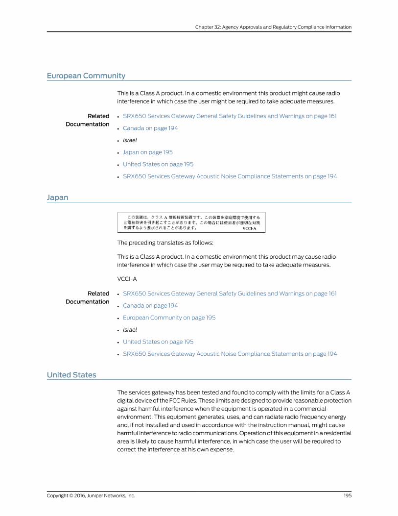
European Community
This is a Class A product. In a domestic environment this product might cause radio
interference in which case the user might be required to take adequate measures.
RelatedDocumentation
SRX650 Services Gateway General Safety Guidelines and Warnings on page 161•
• Canada on page 194
• Israel
• Japan on page 195
• United States on page 195
• SRX650 Services Gateway Acoustic Noise Compliance Statements on page 194
Japan
The preceding translates as follows:
This is a Class A product. In a domestic environment this product may cause radio
interference in which case the user may be required to take adequate measures.
VCCI-A
RelatedDocumentation
SRX650 Services Gateway General Safety Guidelines and Warnings on page 161•
• Canada on page 194
• European Community on page 195
• Israel
• United States on page 195
• SRX650 Services Gateway Acoustic Noise Compliance Statements on page 194
United States
The services gateway has been tested and found to comply with the limits for a Class A
digital device of the FCC Rules. These limits are designed to provide reasonable protection
against harmful interference when the equipment is operated in a commercial
environment. This equipment generates, uses, and can radiate radio frequency energy
and, if not installed and used in accordance with the instruction manual, might cause
harmful interference to radio communications. Operation of this equipment in a residential
area is likely to cause harmful interference, in which case the user will be required to
correct the interference at his own expense.
195Copyright © 2016, Juniper Networks, Inc.
Chapter 32: Agency Approvals and Regulatory Compliance Information
RelatedDocumentation
• SRX650 Services Gateway General Safety Guidelines and Warnings on page 161
• Canada on page 194
• European Community on page 195
• Israel
• Japan on page 195
• SRX650 Services Gateway Acoustic Noise Compliance Statements on page 194
Copyright © 2016, Juniper Networks, Inc.196
SRX650 Services Gateway Hardware Guide

PART 7
Index
• Index on page 199
197Copyright © 2016, Juniper Networks, Inc.

Copyright © 2016, Juniper Networks, Inc.198
SRX650 Services Gateway Hardware Guide
Index
Symbols#, comments in configuration statements....................xv
( ), in syntax descriptions.....................................................xv
< >, in syntax descriptions....................................................xv
[ ], in configuration statements.........................................xv
{ }, in configuration statements.........................................xv
| (pipe), in syntax descriptions...........................................xv
AAC input
line frequency..................................................................58
voltage...............................................................................58
AC power
cord specifications........................................................56
cord types.........................................................................56
AC power cord
connecting on services gateway..............................90
disconnecting on services gateway.......................142
AC power safety guidelines...............................................184
AC power supply
connecting to services gateway...............................89
installing on services gateway..................................78
removing from services gateway.............................141
tools required for connecting....................................89
AC system current rating.....................................................58
accident procedures, electrical........................................183
acoustic noise compliance statement.........................194
agency approvals..................................................................193
agency label, chassis...........................................................152
air filter
hot-swappable.............................................................149
installing on services gateway...................................75
removing from services gateway...........................149
airflow
clearance requirements..............................................50
requirements...................................................................54
altitude, acceptable range..................................................42
autoinstallation, overview...................................................66
automatic configuration......................................................66
Bback panel.................................................................................24
backplane..................................................................................28
basic connectivity
displaying configurations for services
gateway........................................................................115
battery-handling warning...................................................175
boot devices, dual-root partitioning.................................14
braces, in configuration statements.................................xv
brackets
angle, in syntax descriptions......................................xv
square, in configuration statements........................xv
branch SRX
factory default
configuration.........................................................105
built-in Ethernet ports, connecting..................................98
Ccabinet requirements
airflow................................................................................54
clearance...........................................................................53
size.......................................................................................53
cabinet size requirements...................................................53
cables, connecting Ethernet .............................................99
chassis
description.........................................................................17
physical specifications..................................................17
class 1 laser warning.............................................................170
class 1 LED warning...............................................................170
clearance
requirements for airflow.............................................50
requirements for hardware maintenance............50
clearance for cabinet.............................................................53
CLI
connecting at user end for services
gateway........................................................................86
connecting management device...........................102
connecting modem.....................................................104
listing component details..........................................153
locally connecting services gateway.....................102
remotely connecting services gateway...............104
command-line interface See CLI
comments, in configuration statements........................xv
compliance statement, acoustic noise........................194
compliance statements, EMC requirements
Canada.............................................................................194
European Community................................................195
Japan.................................................................................195
United States.................................................................195
199Copyright © 2016, Juniper Networks, Inc.

component details, listing with the CLI........................153
components, packing for shipment...............................156
configuration
basic settings..................................................................96
configuration, required equipment for............................95
connecting
AC power cord................................................................90
CLI at user end................................................................86
services gateway to building structure....................71
tools required for AC power supply........................89
tools required for DC power supply.........................91
tools required for services gateway........................85
connectivity
overview, services gateway........................................95
settings, displaying.......................................................115
console cable connector.....................................................86
console port
connecting modem.....................................................104
connecting services gateway...................................102
control port...............................................................................116
conventions
text and syntax...............................................................xiv
cooling system..........................................................................31
cords, AC power supply........................................................56
curly braces, in configuration statements......................xv
customer support...................................................................xvi
contacting JTAC..............................................................xvi
customer support, contacting..........................................152
Ddamage, preventing ESD....................................................165
DC input, voltage.....................................................................58
DC power supply
connecting to services gateway................................91
installing on services gateway...................................79
removing from services gateway............................143
tools required for connecting.....................................91
DC power supply cable, removing from services
gateway................................................................................144
DC system current rating.....................................................58
depth, of chassis.......................................................................17
device identification...............................................................97
disconnecting AC power cord...........................................142
documentation
comments on...................................................................xv
dual-root partitioning
boot devices......................................................................14
overview..............................................................................14
Eearthquakes, tested toleration for shock.......................42
electrical
accident procedures...................................................183
safety guidelines and warnings..............................183
AC power................................................................184
specifications.........................................................58
wiring..........................................................................55
electrostatic discharge...................................................82, 91
EMC
electromagnetic compatibility..................................55
EMC requirements
Canada.............................................................................194
European Community................................................195
Japan.................................................................................195
United States.................................................................195
encrypted access
through HTTPS.............................................................100
through SSH....................................................................101
through SSL...................................................................100
environmental requirements, lithium battery.............181
environmental specifications.............................................42
ESD See electrostatic discharge
Ethernet cable, connecting services gateway to
management device with...............................................99
Ethernet ports, built-in.........................................................116
Ffactory default configuration
resetting services gateway to..................................134
fan controller.............................................................................31
fan tray
hot-swappable..............................................................147
installing on services gateway...................................75
removing from services gateway............................147
features, services gateway.....................................................3
flange holes, spacing of.......................................................49
font conventions.....................................................................xiv
front panel..................................................................................18
front-mounting services gateway.....................................74
Gge-0/0/0, management port............................................116
ge-0/0/1, control port..........................................................116
GPIMs
backplane.........................................................................28
double-high, double-wide..........................................28
double-high, single-wide............................................28
Copyright © 2016, Juniper Networks, Inc.200
SRX650 Services Gateway Hardware Guide
hot-swappable...............................................................28
network interface card.................................................28
graceful shutdown.................................................................93
grounding
lug specification..............................................................81
points..................................................................................82
services gateway............................................................82
specifications...................................................................81
grounding cable
amperage of.....................................................................81
specifications...................................................................81
guidelines, electrical safety...............................................183
Hheight, of chassis......................................................................17
hot-swappable
GPIMs.................................................................................28
HTTPS (Hypertext Transfer Protocol over SSL)
recommended for secure access..........................100
humidity (relative), acceptable.........................................42
Iimmediate shutdown............................................................93
immunity standards.............................................................193
initial configuration, using setup wizard........................95
installation
checklist............................................................................39
DC power, connecting..................................................33
guidelines ..........................................................................41
overview............................................................................65
preparing site for............................................................39
site guidelines...................................................................41
installing
AC power supply.............................................................78
air filter................................................................................75
DC power supply............................................................79
fan tray................................................................................75
services gateway............................................................39
services gateway in a rack...........................................74
interface cables, organizing on services
gateway..................................................................................85
Jjewelry removal warning.....................................................177
JTAC.............................................................................................151
Juniper Technical Assistance Center See JTAC
Junos OS....................................................................................95
Llabels
agency...............................................................................152
chassis serial number.................................................152
GPIM..................................................................................153
laser beam warning................................................................171
laser safety guidelines.........................................................169
LEDs
class 1 warning...............................................................170
front panel.........................................................................18
POWER..............................................................................92
safety warnings.............................................................169
SRE.......................................................................................18
STATUS.....................................................................93, 134
troubleshooting with...................................................124
levels of safety warnings....................................................159
licenses, for services gateway..............................................4
lightning activity warning....................................................176
lithium battery, compliance specifications..................181
Mmanagement access............................................................101
management port..................................................................116
manuals
comments on...................................................................xv
modem
adapter..............................................................................86
configuring at services gateway end.......................87
configuring at user end................................................86
connecting at services gateway end.......................87
connecting to console port on services
gateway........................................................................86
mounting brackets
holes...................................................................................49
spacing..............................................................................49
NNEBS standards....................................................................193
network cables, organizing on services
gateway..................................................................................85
network interface card, GPIM.............................................28
OOFFLINE button........................................................................12
operating temperature warning.......................................179
overview, installation of services gateway....................65
201Copyright © 2016, Juniper Networks, Inc.
Index

Ppacking services gateway
components for shipment........................................156
required tools and parts............................................154
parentheses, in syntax descriptions.................................xv
partitioning, services gateway............................................14
parts
required for packing.....................................................154
verifying received...........................................................68
Physical Interface Module See GPIMs
physical specifications, chassis..........................................17
plug types...........................................................................56, 58
PoE
overview...............................................................................9
ports......................................................................................9
specifications.....................................................................9
port settings
configuring the modem.......................................86, 87
for connection...............................................................102
services gateway...........................................................116
power
requirements...................................................................60
safety guidelines, AC...................................................184
specifications..................................................................58
POWER LED..............................................................................92
Power over Ethernet See PoE
power supply............................................................................33
hot-swappable...............................................................33
installing AC.....................................................................78
installing DC.....................................................................79
power-up reset.......................................................................134
powering off services gateway..........................................93
powering on services gateway...........................................92
preparing for rack-mount installation..............................71
preparing site for installation.............................................39
preventing ESD damage.....................................................165
product disposal warning..................................................180
Qqualified personnel warning.............................................163
Rrack
installation preparation, services gateway............71
installation, services gateway....................................74
rack requirements
mounting...........................................................................45
size.......................................................................................49
strength.............................................................................49
radiation from open port apertures warning...............172
radio frequency interference See RFI
relative humidity, acceptable.............................................42
removing
AC power supply............................................................141
air filter.............................................................................149
fan tray..............................................................................147
removing DC power supply................................................143
removing DC power supply cable...................................144
repair policies..........................................................................152
RESET CONFIG button..................................................12, 134
resetting services gateway................................................134
power-up.........................................................................134
RESET CONFIG button...............................................134
restricted access area warning........................................162
return materials authorization See RMA
return procedure....................................................................152
RFI
radio frequency interference......................................55
RMA
return materials authorization.................................152
Ssafety guidelines, laser........................................................169
safety requirements
guidelines........................................................................162
warnings...........................................................................162
safety warning levels, definition......................................159
secure access
CLI requirements...........................................................101
HTTPS recommended..............................................100
overview..........................................................................100
Telnet versus SSH.........................................................101
Web requirements.......................................................100
Secure Sockets Layer See SSL
seismic (earthquake), tested level...................................42
serial number label, chassis..............................................152
serial number label, GPIM..................................................153
services gateway
back panel........................................................................24
connecting AC power cord.........................................90
connecting to the setup wizard................................98
description...........................................................................3
disconnecting AC power cord..................................142
establishing secure Web access............................100
front panel.........................................................................18
HTTPS Web access....................................................100
installing AC power supply.........................................78
installing DC power supply.........................................79
Copyright © 2016, Juniper Networks, Inc.202
SRX650 Services Gateway Hardware Guide

packing for shipment..................................................155
removing AC power supply........................................141
removing DC power supply.......................................143
removing DC power supply cable..........................144
returning...........................................................................152
SSH access......................................................................101
SSL access.....................................................................100
supported GPIMs...........................................................28
tools required for powering on...................................81
setup wizard, connecting services gateway.................98
shipment
packing components..................................................156
packing services gateway..........................................155
show chassis hardware command.................................153
shutting down services gateway.......................................93
graceful..............................................................................93
immediate........................................................................93
signaling limitations...............................................................55
site, environmental specifications....................................42
specifications, environmental............................................42
SSH, connecting to services gateway............................101
SSL (Secure Sockets Layer)
management access..................................................100
standards compliance........................................................193
STATUS LED....................................................................93, 134
support, requesting from JTAC.................................151, 154
support, technical See technical support
surge protector..................................................................89, 91
syntax conventions................................................................xiv
system time...............................................................................97
Ttechnical support
contacting JTAC..............................................................xvi
telnet, connecting to services gateway.........................101
temperature, acceptable range.........................................42
thermal output........................................................................42
time zone....................................................................................97
tolerances..................................................................................42
tools required for
connecting AC power supply....................................89
connecting DC power supply.....................................91
connecting services gateway....................................85
grounding...........................................................................81
installing............................................................................65
packing.............................................................................154
powering off......................................................................81
powering on......................................................................81
replacing hardware components............................137
unpacking..........................................................................67
Uunpacking
required tools and parts..............................................67
services gateway............................................................67
Vverifying parts received with services gateway...........68
Wwarnings
battery-handling...........................................................175
class 1 laser......................................................................170
class 1 LED.......................................................................170
electrical safety guidelines.......................................183
general...............................................................................161
jewelry removal..............................................................177
laser beam........................................................................171
lightning activity............................................................176
operating temperature...............................................179
product disposal..........................................................180
rack-mount requirements..........................................45
radiation from open apertures.................................172
weight, of chassis.....................................................................17
width, of chassis.......................................................................17
wrist strap, for grounding..............................................89, 91
XXPIMs
double-high, double-wide..........................................28
double-high, single-wide............................................28
single-high, single-wide...............................................28
203Copyright © 2016, Juniper Networks, Inc.
Index

Copyright © 2016, Juniper Networks, Inc.204
SRX650 Services Gateway Hardware Guide


