37
Technical/Erection Information SS360

Technical/Erection Information
SS360

TABLE OF CONTENTS
GENERAL INFORMATION
Product Checklist . . . . . . . . . . . . . . . . . . . . . . . . . . . . . . . . . . . . . . . . . . . . . . . . . . . .. . . . . . . SS360 – 3-8 Insulation and Fastener Recommendations………………………………..…………..………………..SS360 - 9 Preparatory Requirements . . . . . . . . . . . . . . . . . . . . . . . . . . . . . . . . . . . . . . . . . .. . . . . . . .. . ..SS360 - 10 Unloading . . . . . . . . . . . . . . . . . . . . . . . . . . . . . . . . . . . . . . . . . . . . . . . . . .. . . . . . . . ..SS360 - 11 Handling & Storage . . . . . . . . . . . . . . . . . . . . . . . . . . . . . . . . . . . . . . . . . . . . . . . . . . . . . .... . . . ..SS360 – 12 -13
ERECTION SEQUENCE Step 1 — Rake Support . . . . . . . . . . . . . . . . . . . . . . . . . . . . . . . . . . . . . . . . . … . . . . . .. . SS360 - 14 Step 2 — Eave Plate . . . …………………… . . . . . . . . . . . . . . . . . . . . . . . . . . . . . . . . . . . . SS360 - 15 Step 3 — Metal Inside Closure . . . . . . . . . . . . . . . . . . . . . . . . . . . . . . . . . . . . . . . . ……….SS360 - 16 Step 4 — Thermal Spacer . . . . . . . . . . . . . . . . . . . . . . . . . . . .. . …………………………….SS360 - 17 Step 5 — First Panel . . . . . . . . . . . . . . . . . . . . . . . . . . . . . . . . . . . . . . . . . . . . . . . .. ………SS360 - 18-19 Step 6 — Clip Installation . . . . . . . . . . . . . . . . . . . . . . . . . . . . . . . . . . . . . . . . . . . . . . . . .. SS360 - 20 Step 7 — Back-Up Plate . . . . . . . . . . . . . . . . . . . . . . . . . . . . . . . . . . . . . . . . . . . . . . . . .. . SS360 - 21 Step 8 — Endlap Panel . . . . . . . . . . . . . . . . . . . . . . . . . . . . . . . . . . . . . . . . . . . . . . . . . . . SS360- 22-23 Step 9 — Ridge Panel . . . . . . . . . . . . . . . . . . . . . . . . . . . . . . . . . . . . . . . . . . . . . . . . . . . . .SS360 - 24 Step 10 — Subsequent Runs Eave . . . . . . . . . . . . . . . . . . . . . . . . . . . . . . . . . . . . . . . . . . . .SS360 - 25 Step 11 — Subsequent Runs Endlap . . . . . . . . . . . . . . . . . . . . . . . . . . . . . . . . . . . . . . . . . .SS360 – 26-27 Step 12 --- Subsequent Runs Ridge . . . . . . . . . . . . . . . . . . . . . . . . . . . . . . . . . . . . . . . . . . ..SS360 - 28 Step 13 — Seaming Panel Sidelaps . . . . . . . . . . . . . . . . . . . . . . . . . . . . . . . . . . . . . . . . . . . SS360 – 29-30 Step 14 — Last Panel Run . . . . . . . . . . . . . . . . . . . . . . . . . . . . . . . . . . . . . . . . . . . . . . . . . .SS360 - 31 Step 15 – Outside Closure . . . . . . . . . . . . . . . . . . . . . . . . . . . . . . . . . . . . . . . . . . . . . . . . . . SS360 – 32-33 Step 16 — Ridge-Outside Closure/Flashing . . . . . . . . . . . . . . . . . . . . . . . . . . . . . . . . . . . . . SS360 - 34
SPECIAL ERECTION TECHNIQUES
Special Erection Techniques . . . . . . . . . . . . . . . . . . . . . . . . . . . . . . . . . . . . . . . . . . . . . . . …….SS360 - 35-36
SS360 Table of Contents

KLS
IMPORTANT NOTICE
READ THIS MANUAL COMPLETELY PRIOR TO BEGINNING THE INSTALLATION OF THE SS360 ROOFING SYSTEM.
IF THERE IS A CONFLICT BETWEEN PROJECT ERECTION DRAWINGS PROVIDED OR APPROVED BY THE MANUFACTURER AND DETAILS IN THIS MANUAL, PROJECT ERECTION DRAWINGS WILL TAKE PRECEDENCE.
Ice Dam Disclaimer Kirby’s standing seam roofs meet the load requirements dictated by governing codes and project specifications, including applicable snow loads. However, Kirby expressly disclaims responsibility for weather tightness or roof point loading issues or other hazards resulting from ice dam situations. Any time ice and snow can melt on the main body of the roof and refreeze at the eave or in the shadow of an adjacent wall, an ice dam situation may develop. In addition to local climate, ice dam formation is affected by many other factors, including but not limited to, roof insulation R value , roof panel color, interior temperature of building, heater location in building, eave overhangs, parapet walls, shading of building roof areas from adjacent trees, parapets, buildings, etc. These factors are design and maintenance issues and are outside the control of Kirby. Kirby specifically disclaims any liability for damage due to ice dam formation, although the following issues should be taken into consideration concerning standing seam roofs installed in freezing climates:
• Always use field seamed panels. These machine-folded seams are more durable when subjected to occasional icing.
• Eliminate "cold" eave overhangs and parapet walls from the building design. Roof overhangs outside the heated envelope of the building will tend to be colder than the roof areas over the heated envelope. Simple roof designs are preferred. Parapet walls at the eave allow ice and snow to collect due to shading effects and the lower roof temperatures caused thereby.
• Make sure the interior of the building is adequately insulated and the heating is properly distributed. Inadequate insulation in the roof and/or improper heat distribution causes heat flow though the main body of the roof. On days when the temperature is below freezing, this heat gain can cause ice and snow to melt and refreeze at the eave where the roof is colder.
• Lay out the building to prevent the eaves and other roof areas from being shaded during the winter. This may mean eliminating adjacent trees or reconsidering roof geometries.
• Consider using self-regulating heating cables at the eaves to mitigate the effects of ice dams. • On building designs using attics, over-insulate the attic floor and provide adequate ventilation in
the attic. This will reduce heat transfer through the roof resulting in more consistent roof temperatures between eave and field of roof.
• Increase the degree of diligence with respect to underlayment materials at roof areas prone to icing. This may include valleys, eaves, dormers and roof areas near dormers, parapets and the like where shading may occur.
For more information on this subject, please refer to the MCA's Metal Roof Design for Cold Climates manual.
©Copyright Kirby Building Systems 2007. All Rights Reserved. 07-09
Descriptions and specifications contained herein were in effect at the time this publication was approved for printing. In a continuing effort to refine and improve products, the manufacturer reserves the right to discontinue products at any time or change specifications and/or designs without incurring obligation. To insure you have the latest information available, please inquire. Application details in this manual may not be appropriate for all environmental conditions, building designs, or panel profiles. Projects should be engineered to conform to applicable building codes, regulations, and accepted industry practices. Insulation is not shown in these details for clarity.
SS360 Notice

SS360 General Information
PRODUCT CHECKLIST
SS360 PANEL (SS3) 24 GA. (22 GA. OPTION)
FACTORY APPLIED MASTIC PRE-NOTCHED PRE-DIMPLED
PANEL CLIP (SSC01) LOW FLOATING 3 3/8” HIGH
PANEL CLIP w/ HOOD (SSC11) LOW FLOATING 3 3/8” HIGH
PANEL CLIP (SSC02) HIGH FLOATING 4 3/8” HIGH
PANEL CLIP w/ HOOD (SSC12) HIGH FLOATING 4 3/8” HIGH
BACK-UP PLATE (SBP01) 16 GA. GALV. USED AT ENDLAP
PANEL CLIP (SSC02)
HIGH FLOATING 4 3/8” HIGH

SS360 General Information
PRODUCT CHECKLIST
LOW RAKE SUPPORT (RSL20) 14 GA. PAINTED USED WITH LOW SYSTEM
HIGH RAKE SUPPORT (RSH20) 14 GA. PAINTED USED WITH HIGH SYSTEM
LOW RAKE SUPPORT ANGLE (RSAL20) 14 GA. PAINTED FOR OFF MODULE FINISH WITH LOW SYSTEM
HIGH RAKE SUPPORT ANGLE (RSAH20) 14 GA. PAINTED FOR OFF MODULE FINISH WITH HIGH SYSTEM
LOW RAKE SUPPORT PLATE (RLA410) 14 GA. PAINTED FOR OFF MODULE FINISH WITH HIGH SYSTEM
HIGH RAKE SUPPORT PLATE (RHA410) 14 GA. PAINTED FOR OFF MODULE FINISH WITH HIGH SYSTEM
438"
338"
138"
38"
SS360 General Information
PRODUCT CHECKLIST
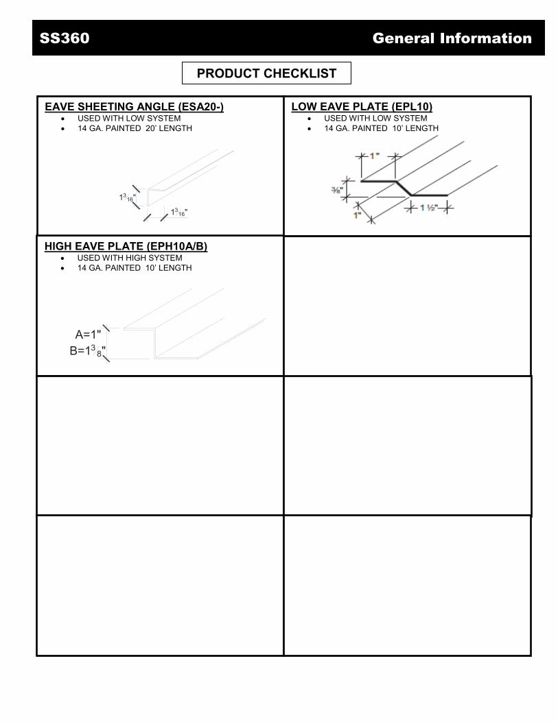
EAVE SHEETING ANGLE (ESA20-) USED WITH LOW SYSTEM 14 GA. PAINTED 20’ LENGTH
LOW EAVE PLATE (EPL10) USED WITH LOW SYSTEM 14 GA. PAINTED 10’ LENGTH
HIGH EAVE PLATE (EPH10A/B) USED WITH HIGH SYSTEM 14 GA. PAINTED 10’ LENGTH
1316"
1316"
A=1"B=13
8"

SS360 General Information
PRODUCT CHECKLIST
OUTSIDE CLOSURE (SLMC3) USED AT RIDGE OR HIGH EAVE
INSIDE CLOSURE (MEC01) USED AT LOW EAVE
TAPE SEALANT (STP02) 3/16” x 7/8” DOUBLE BEAD x 40’ ROLL USED AT EAVES, OUTSIDE CLOSURES AND TRIM
CONNECTIONS
TAPE SEALANT (STP03) 3/16” x 2 1/2” TRIPLE BEAD x 20’ ROLL USED AT ENDLAPS, CURBS AND VALLEYS
TAPE SEALANT (STP04)
7/32” x 1 3/8” x 4” BEVELED USED TO FILL VOID AT MINOR RIBS OF PANEL AT
LOW EAVES AND VALLEYS
BUTYL CAULK (H3151) USED AT EAVE, ENDLAPS, RIDGE AND HIGH SIDE
TUBE SEALANT (TS--) USED AT TRIM LAPS
THERMAL BLOCK (SYB--) POLYSTYRENE BLOCK USED TO INCREASE
INSULATION CAPACITY ALONG PURLINS
3/8”,3/4”, 1” or 1 ¼”
SS360 General Information
PRODUCT CHECKLIST
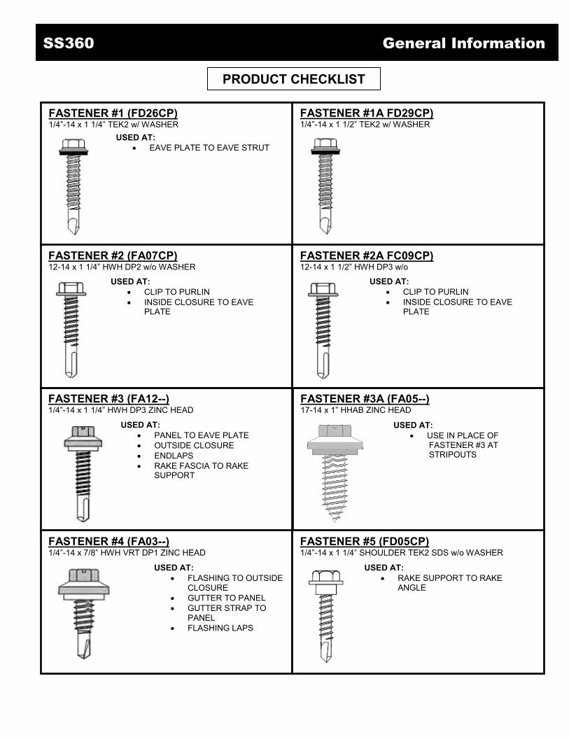
FASTENER #1 (FD26CP) 1/4”-14 x 1 1/4” TEK2 w/ WASHER
FASTENER #1A FD29CP) 1/4”-14 x 1 1/2” TEK2 w/ WASHER
FASTENER #2 (FA07CP) 12-14 x 1 1/4” HWH DP2 w/o WASHER
FASTENER #2A FC09CP) 12-14 x 1 1/2” HWH DP3 w/o
FASTENER #3 (FA12--) 1/4”-14 x 1 1/4” HWH DP3 ZINC HEAD
FASTENER #3A (FA05--) 17-14 x 1” HHAB ZINC HEAD
FASTENER #4 (FA03--) 1/4”-14 x 7/8” HWH VRT DP1 ZINC HEAD
FASTENER #5 (FD05CP) 1/4”-14 x 1 1/4” SHOULDER TEK2 SDS w/o WASHER
USED AT: EAVE PLATE TO EAVE STRUT
USED AT: CLIP TO PURLIN INSIDE CLOSURE TO EAVE
PLATE
USED AT: CLIP TO PURLIN INSIDE CLOSURE TO EAVE
PLATE
USED AT: PANEL TO EAVE PLATE OUTSIDE CLOSURE ENDLAPS RAKE FASCIA TO RAKE
SUPPORT
USED AT: USE IN PLACE OF FASTENER #3 AT STRIPOUTS
USED AT: FLASHING TO OUTSIDE
CLOSURE GUTTER TO PANEL GUTTER STRAP TO
PANEL FLASHING LAPS
USED AT: RAKE SUPPORT TO RAKE
ANGLE

SS360 General Information
PRODUCT CHECKLIST
SS360 DUCKBILL VISE GRIP (S3PVG) USED AT PANEL ENDLAPS
SS360 LOCKING CLAMP (SSPLC) USED AT PANEL ENDLAPS
SS360 General Information
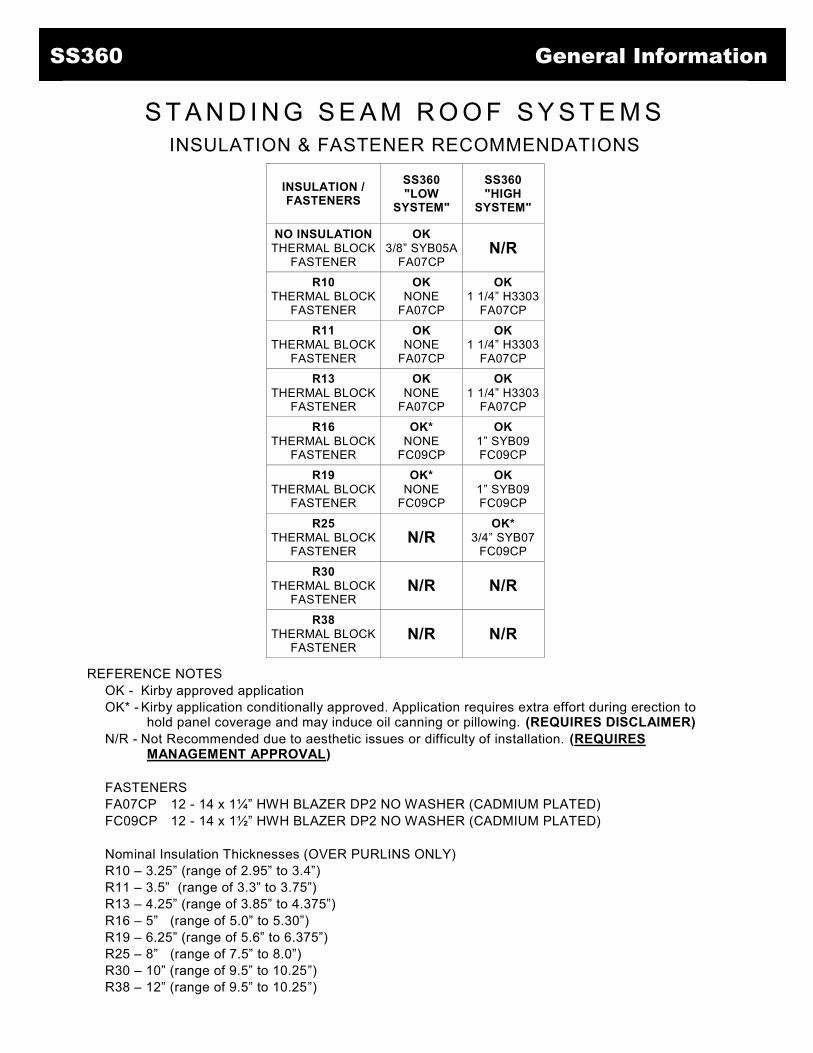
S T A N D I N G S E A M R O O F S Y S T E M S INSULATION & FASTENER RECOMMENDATIONS
INSULATION / FASTENERS
SS360 "LOW
SYSTEM"
SS360 "HIGH
SYSTEM"
NO INSULATION THERMAL BLOCK
FASTENER
OK 3/8” SYB05A
FA07CP N/R
R10 THERMAL BLOCK
FASTENER
OK NONE
FA07CP
OK 1 1/4” H3303
FA07CP R11
THERMAL BLOCK FASTENER
OK NONE
FA07CP
OK 1 1/4” H3303
FA07CP R13
THERMAL BLOCK FASTENER
OK NONE
FA07CP
OK 1 1/4” H3303
FA07CP R16
THERMAL BLOCK FASTENER
OK* NONE
FC09CP
OK 1” SYB09 FC09CP
R19 THERMAL BLOCK
FASTENER
OK* NONE
FC09CP
OK 1” SYB09 FC09CP
R25 THERMAL BLOCK
FASTENER N/R
OK* 3/4” SYB07
FC09CP
R30 THERMAL BLOCK
FASTENER N/R N/R
R38 THERMAL BLOCK
FASTENER N/R N/R
REFERENCE NOTES OK - Kirby approved application OK* - Kirby application conditionally approved. Application requires extra effort during erection to
hold panel coverage and may induce oil canning or pillowing. (REQUIRES DISCLAIMER) N/R - Not Recommended due to aesthetic issues or difficulty of installation. (REQUIRES
MANAGEMENT APPROVAL) FASTENERS FA07CP 12 - 14 x 1¼” HWH BLAZER DP2 NO WASHER (CADMIUM PLATED) FC09CP 12 - 14 x 1½” HWH BLAZER DP2 NO WASHER (CADMIUM PLATED) Nominal Insulation Thicknesses (OVER PURLINS ONLY) R10 – 3.25” (range of 2.95” to 3.4”) R11 – 3.5” (range of 3.3” to 3.75”) R13 – 4.25” (range of 3.85” to 4.375”) R16 – 5” (range of 5.0” to 5.30”) R19 – 6.25” (range of 5.6” to 6.375”) R25 – 8” (range of 7.5” to 8.0”) R30 – 10” (range of 9.5” to 10.25”) R38 – 12” (range of 9.5” to 10.25”)

1. Read and understand contents of this manual before proceeding with roof installation. Contact Field Services with any questions. 2. The walls do not have to be erected before the roof is installed. However, for the purpose of this
manual, we have assumed that the wall panels have been installed. 3. All primary and secondary framing must be erected, plumbed, and squared with bolts tightened
according to accepted building practices. It is recommend that surveying equipment be used to check building alignment.
4. The substructure (eave to ridge) must be on plane with a tolerance of 1/4" in 20' and 3/8" in 40'. 5. Make sure a rake angle or an alternate structural flat surface has been installed on top of the purlins
to accept the “Rake Support”. 6. SS360 can be erected on various types of construction. However, for the purpose of this manual, we
have assumed that the roof will be installed on a new, pre-engineered metal building. When there is a conflict between this manual and the Erection Drawings, the Erection Drawings will govern.
7. Kirby recommends the use of a screw gun with a speed range of 0 - 2000 RPM to properly install all fasteners referenced in this manual. Tools rated to 4000 RPM should never be used for self drilling fasteners typically supplied with metal building components.
8. Field cutting of the panels should be avoided where possible. If field cutting is required, the panels must be cut with nibblers, snips, or shears to prevent edge rusting. Do not cut the panels with saws, abrasive blades, grinders, or torches.
SS360 Preparatory Requirements
NOTE It is the responsibility of the erector to install this roof using safe construction practices that are in compliance with OSHA regulations. The manufacturer is not responsible for the performance of this roof system if it is not installed in accordance with the instructions shown in this manual. Deviations from these instructions and details must be approved in writing by the manufacturer.
REVISED 3-9-2017 SUBJECT TO CHANGE WITHOUT NOTICE SS360 - 10

PANEL SHIPMENT Upon receiving material, check shipment against shipping list for shortages and dam- ages. Kirby will not be responsible for shortages or damages unless they are noted on the shipping list. The panels are banded together, causing them to curl up. This enhances the strength of the bundles. Panels bundled in this manner may be handled by a forklift in lengths p to 30’.Lengths in excess of 30’ must be lifted with a spreader bar.
UNLOADING Each bundle should be lifted at its center of gravity. Where possible, bundles should remain banded until final placement on roof. If bundles must be opened, they should be retied before lifting. When lifting bundles with a crane, a spreader bar and nylon straps should be used. NEVER USE WIRE ROPE OR CHAIN SLINGS. THEY WILL DAMAGE THE PANELS. When lifting bundles with a forklift, forks must be a minimum of five feet apart. Do not trans- port open bundles. Drive slowly when crossing rough terrain to prevent panel buckling.
SS360 Unloading
CAUTION Improper unloading and handling of
bundles and crates may cause bodily injury or material damage. The
manufacturer is not responsible for bodily injuries or material damages
during unloading and storage.
REVISED 3-9-2017 SUBJECT TO CHANGE WITHOUT NOTICE SS360 - 11

Handling Standing on one side of the panel, lift it by the seam. If the panel is over 10' long, lift it with two or more people on one side of the panel to prevent buckling. Do not pick panels up by the ends.
Storage
Check to see that moisture has not formed inside the bundles during shipment. If moisture is present, panels should be unbundled and wiped dry, then restacked and loosely covered so that air can circulate between the panels. Store bundled sheets off the ground sufficiently high enough to allow air circulation beneath bundle and to prevent rising water from entering bundle. Cover the area beneath panels with polyethylene or a tarpaulin. Slightly elevate one end of bundle. Prevent rain from entering bundle by covering with tarpaulin, making provision for air circulation between draped edges of tarpaulin and the ground. PROLONGED STORAGE OF SHEETS IN A BUNDLE IS NOT RECOMMENDED. If conditions do not permit immediate erection, extra care should be taken to protect sheets from staining or water marks.
SS360 Handling/Storage
NOTE Protective gloves should always be used while handling panels. OSHA safety regulations must be followed at all times.
REVISED 3-9-2017 SUBJECT TO CHANGE WITHOUT NOTICE SS360 - 12

Panel Layout The SS360 panels are non-handed therefore, the roof can be sheeted in either direction in most cases. Consult the Erection Drawings for job specific details. For roofs requiring endlaps, the SS360 panel endlaps are staggered, occurring on alternating purlins. The first panel run must use the short eave panel length.
Bundle Placement
Bundles can be lifted and placed on the roof to facilitate handling. The bundles must be placed directly over a frame and the purlins must be blocked. Do NOT slide bundles along roof framing.
SS360 Handling/Storage
REVISED 3-9-2017 SUBJECT TO CHANGE WITHOUT NOTICE SS360 - 13
2
13
42
13
42
13
42
13
42
1
2
13
42
13
42
13
42
13
42
1
SIDEWALL
SIDEWALL
RIDGE

Rake Support Attach the rake support on top of the rake angle with fastener # 5 at 2'-0" centers with a fastener in the first and last pre-punched slot. The vertical leg is to be installed square with the eave. Center fasteners in slots. Make sure to hold back rake support angle 2 3/4" from low eave, high eave, and ridge to allow for expansion and contraction of the roof. IT IS IMPORTANT THAT THE RAKE SUPPORT IS INSTALLED STRAIGHT AND SQUARE WITH THE EAVE AS, IT CONTROLS THE ALIGNMENT OF THE ROOF SYSTEM. Install 6" pieces of double faced tape (not by building manufacturer) on 3'-0" centers to the top of the horizontal leg of the rake support. This will help hold the insulation in place at the rake.
STEP
1
CAUTION It is important that shoulder
fasteners are installed through the CENTER of the slotted holes of the rake support to allow for expansion
and contraction.
SS360 Erection Sequence
FASTENER # 5 (2'-0" O/C)
RAKE ANGLE
RAKE SUPPORT
PURLIN
REVISED 3-9-2017 SUBJECT TO CHANGE WITHOUT NOTICE SS360 - 14

Eave Plate
Install eave plates flush with the outside of the high crowns of the wall panels. Install with Fastener #1 at 1'-0" on center. The end of the eave plate will butt align with the outside edge of the rake support. All of the eave plates may be installed at this time. Be sure to butt each eave plate end to end without leaving a gap between the plates. Install eave trim to the top of the eave plates with pop rivets. Use three rivets per 10' piece. Trim must be pulled tight to wall panels before fastening to eave plates. Install double faced tape along the length of the interior leg of the eave strut.
TRIM LAPS Lap eave trim 1". Apply two beads of urethane sealant between the trim pieces, approximately 1/2" from the end of the bottom piece.
STEP
2
SS360 Erection Sequence
REVISED 3-9-2017 SUBJECT TO CHANGE WITHOUT NOTICE SS360 - 15

Inside Closure Prior to installing each inside closure, cut a 5” long piece of 3/16” x 2 ½’ tape sealant and apply it to the bottom of the inside closure. Align the center of the first inside closure with the outside edge of the rake support. Then using Fastener #2, attach the first inside closure to the eave plate, locating the face of the inside closure with the downslope edge of the closure trim. Locate additional closures on 24" centers from the first closure to maintain panel module, attaching each with Fastener #2. Install two fasteners per closure. To maintain panel module, metal inside closures must be installed on 24" centers. Place Double-Bead tape sealer across the top of the closure trim, the side and top of each closure. This tape should tie into the tape under the inside closure with no gaps to complete the seal at the eave. Roll out insulation from eave to peak, laying the side of the insulation on top of the rake support. The first roll should be 3' wide. This will keep insulation sidelaps 1' from panel sidelaps. Allow approximately 4" of insulation to hang past the double faced tape (downslope) before sticking the insulation to the double faced tape. Cut and remove the fiberglass approximately 4" and fold the vapor barrier back over the insulation (upslope).
SS360 Erection Sequence
STEP
3
CAUTION The fiberglass insulation must not interfere with the Tape Sealant.
REVISED 3-9-2017 SUBJECT TO CHANGE WITHOUT NOTICE SS360 - 16

Thermal Blocks (If Required)
Position the thermal spacer on top of the insulation over each purlin and against the rake support prior to installing the roof panel. Spay adhesive (not by Kirby) may be used to adhere the Thermal Block to the insulation.
SS360 Erection Sequence
STEP
4
REVISED 3-9-2017 SUBJECT TO CHANGE WITHOUT NOTICE SS360 - 17
REVISED 7-26-2016 SUBJECT TO CHANGE WITHOUT NOTICE SS360 - 15

FIRST PANEL
Apply minor rib tape sealer to the under- side of the minor ribs of the panel. Position so that this tape sealer will cross the Double Bead tape sealer on the eave trim. Position the panel so that it overhangs the eave strut by the thickness of the wall covering plus 3". The upper end of the panel must be 1’-0" beyond the web of the purlin. Lay the female lip of the panel over the rake support. To prevent wind damage, secure the female lip to the rake support with a "C" clamp or temporary pop rivet. Pop rivet must go through rake support. The panel will not be fastened permanently to the rake support until the rake trim is installed.
SS360 Erection Sequence
STEP
5
REVISED 3-9-2017 SUBJECT TO CHANGE WITHOUT NOTICE SS360 - 18
REVISED 7-26-2016 SUBJECT TO CHANGE WITHOUT NOTICE SS360 - 16
REVISED 7-26-2016 SUBJECT TO CHANGE WITHOUT NOTICE SS360 - 15
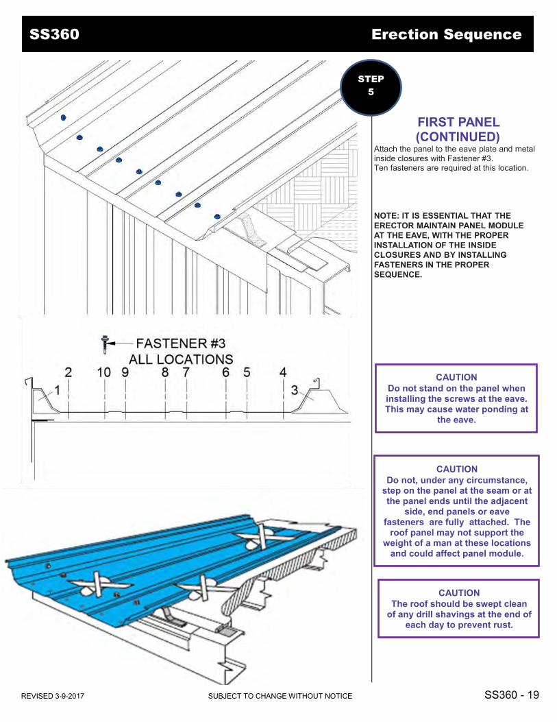
FIRST PANEL (CONTINUED)
Attach the panel to the eave plate and metal inside closures with Fastener #3. Ten fasteners are required at this location. NOTE: IT IS ESSENTIAL THAT THE ERECTOR MAINTAIN PANEL MODULE AT THE EAVE, WITH THE PROPER INSTALLATION OF THE INSIDE CLOSURES AND BY INSTALLING FASTENERS IN THE PROPER SEQUENCE.
SS360 Erection Sequence
STEP
5
SS360 Erection Sequence
CAUTION Do not stand on the panel when installing the screws at the eave. This may cause water ponding at
the eave.
CAUTION Do not, under any circumstance,
step on the panel at the seam or at the panel ends until the adjacent
side, end panels or eave fasteners are fully attached. The
roof panel may not support the weight of a man at these locations
and could affect panel module.
CAUTION The roof should be swept clean
of any drill shavings at the end of each day to prevent rust.
REVISED 3-9-2017 SUBJECT TO CHANGE WITHOUT NOTICE SS360 - 19 REVISED 7-26-2016 SUBJECT TO CHANGE WITHOUT NOTICE SS360 - 16
REVISED 7-26-2016 SUBJECT TO CHANGE WITHOUT NOTICE SS360 - 15

Install a clip on the male leg of the panel at the support member on the high end of the panel. This should be the first clip installed as it controls the 24" module for the remainder of the panel. Check panel module before proceeding with installation. Install clips at each support members for the remaining length of the panel.
SS360 Erection Sequence
STEP
6
SS360 Erection Sequence
CAUTION Insure that the sliding tab of the clip is centered before attaching
to the support member.
IMPORTANT As each clip is installed, maintain panel module.
REVISED 3-9-2017 SUBJECT TO CHANGE WITHOUT NOTICE SS360 - 20 REVISED 7-26-2016 SUBJECT TO CHANGE WITHOUT NOTICE SS360 - 16
REVISED 7-26-2016 SUBJECT TO CHANGE WITHOUT NOTICE SS360 - 15

Slide a back-up plate onto the high end of panel; make sure the teeth on top of the back-up plate are on top of the panel. Measure 5 ¾” down from the high end of the panel. Place Triple Bead Tape Sealant at this location. The tape should be continuous covering the female rib across the panel and on top of the shoulder below the male rib. Fill the area on the male rib above the Tape Sealant with Butyl Caulk.
SS360 Erection Sequence
STEP
7
SS360 Erection Sequence
NOTE Steps 7 and 8 apply only where
more than one panel is used on a single plane.
CAUTION Forcing the tape sealer back into the corners will lessen the thickness of the tape sealer where it is needed most.
REVISED 3-9-2017 SUBJECT TO CHANGE WITHOUT NOTICE SS360 - 21 REVISED 7-26-2016 SUBJECT TO CHANGE WITHOUT NOTICE SS360 - 16
REVISED 7-26-2016 SUBJECT TO CHANGE WITHOUT NOTICE SS360 - 15

STANDARD ENDLAP
Install the upper panel by lapping the lower panel 6” and roll/setting the female seam over the lower panel female seam and the Rake Support. Hold the middle of the upper panel up and slide the 3” notch under the lower panel male seam. The lower and upper panel notches should now butt together to form a continuous seam.
SS360 Erection Sequence
STEP
8
SS360 Erection Sequence
IMPORTANT Prior to installing uphill panel, apply a 6” long bead of Butyl Caulk in the female leg to meet the factory applied caulk at the each end of the panel.
REVISED 3-9-2017 SUBJECT TO CHANGE WITHOUT NOTICE SS360 - 22 REVISED 7-26-2016 SUBJECT TO CHANGE WITHOUT NOTICE SS360 - 16
REVISED 7-26-2016 SUBJECT TO CHANGE WITHOUT NOTICE SS360 - 15

ENDLAP (Continued)
Relax the middle of the upper panel onto the tape mastic on the lower panel. Clamp the male seams together as shown before installing any fasteners. Secure the endlap by installing (10) Fastener #3 at panel dimple locations. Do NOT remove clamp until all fasteners are installed. Beginning at the high end of the panel, install clips at each support members for the length of the panel. Refer to Step 6. Repeat the endlap procedures as required for each panel until the ridge or high eave is reached.
SS360 Erection Sequence
STEP
8
SS360 Erection Sequence
CAUTION The roof should be swept clean of any drill shavings at the end
of each day to prevent rust.
CAUTION Do not stand on the panel when
installing the screws at the endlap. This may cause water
ponding at the eave.
REVISED 3-9-2017 SUBJECT TO CHANGE WITHOUT NOTICE SS360 - 23 REVISED 7-26-2016 SUBJECT TO CHANGE WITHOUT NOTICE SS360 - 16
REVISED 7-26-2016 SUBJECT TO CHANGE WITHOUT NOTICE SS360 - 15

RIDGE PANEL Beginning at the high end of the panel, install clips at each support members for the length of the panel. Refer to Step 6. Check panel module before proceeding with installation. Make adjustments if required. Slide a back-up plate onto the high end of panel; make sure the teeth on top of the back-up plate are on top of the panel.
SS360 Erection Sequence
IMPORTANT Prior to installing panel, apply a 6” long bead of Butyl Caulk in the female leg to meet the factory applied caulk at the each end of the panel.
STEP
9
SS360 Erection Sequence
REVISED 3-9-2017 SUBJECT TO CHANGE WITHOUT NOTICE SS360 - 24 REVISED 7-26-2016 SUBJECT TO CHANGE WITHOUT NOTICE SS360 - 16
REVISED 7-26-2016 SUBJECT TO CHANGE WITHOUT NOTICE SS360 - 15
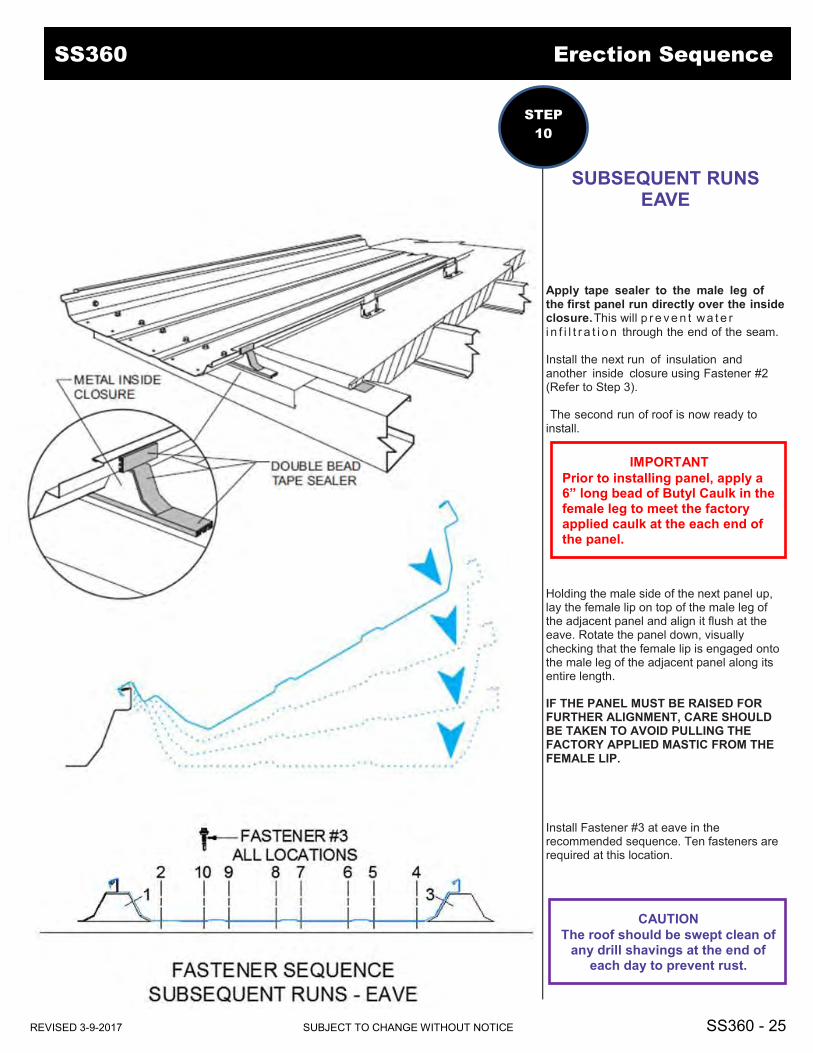
SUBSEQUENT RUNS EAVE
Apply tape sealer to the male leg of the first panel run directly over the inside closure. This will p r e ve n t wa t e r i n f i l t r a t i o n through the end of the seam. Install the next run of insulation and another inside closure using Fastener #2 (Refer to Step 3). The second run of roof is now ready to install. Holding the male side of the next panel up, lay the female lip on top of the male leg of the adjacent panel and align it flush at the eave. Rotate the panel down, visually checking that the female lip is engaged onto the male leg of the adjacent panel along its entire length. IF THE PANEL MUST BE RAISED FOR FURTHER ALIGNMENT, CARE SHOULD BE TAKEN TO AVOID PULLING THE FACTORY APPLIED MASTIC FROM THE FEMALE LIP. Install Fastener #3 at eave in the recommended sequence. Ten fasteners are required at this location.
SS360 Erection Sequence
STEP
10
SS360 Erection Sequence
IMPORTANT Prior to installing panel, apply a 6” long bead of Butyl Caulk in the female leg to meet the factory applied caulk at the each end of the panel.
CAUTION The roof should be swept clean of
any drill shavings at the end of each day to prevent rust.
REVISED 3-9-2017 SUBJECT TO CHANGE WITHOUT NOTICE SS360 - 25 REVISED 7-26-2016 SUBJECT TO CHANGE WITHOUT NOTICE SS360 - 16
REVISED 7-26-2016 SUBJECT TO CHANGE WITHOUT NOTICE SS360 - 15

SUBSEQUENT RUNS ENDLAP
Install the Back-Up Plate and sealant as shown in Step 7 on the lower panel. Install the upper panel by lapping the lower panel 6” and roll/setting the female seam over the adjacent panel male seam. Hold the middle of the upper panel up and slide the 3” notch under the lower panel male seam. The lower and upper panel notches should now butt together to form a continuous seam.
SS360 Erection Sequence
IMPORTANT Prior to installing panel, apply a 6” long bead of Butyl Caulk in the female leg to meet the factory applied caulk at the each end of the panel.
STEP
11
SS360 Erection Sequence
NOTE Steps 11 applies only where more
than one panel is used on a single plane.
REVISED 3-9-2017 SUBJECT TO CHANGE WITHOUT NOTICE SS360 - 26 REVISED 7-26-2016 SUBJECT TO CHANGE WITHOUT NOTICE SS360 - 16
REVISED 7-26-2016 SUBJECT TO CHANGE WITHOUT NOTICE SS360 - 15

SUBSEQUENT RUNS ENDLAP (CONTINUED)
Relax the middle of the upper panel onto the tape mastic on the lower panel. Clamp the male and female ribs as shown before installing any fasteners. Secure the endlap by installing (10) Fastener #3 at panel dimple locations. Do NOT remove clamps until all fasteners are installed. Beginning at the high end of the panel, install clips at each support members for the length of the panel. Refer to Step 6. Repeat the endlap procedures as required for each panel until the ridge or high eave is reached.
SS360 Erection Sequence
STEP
11
SS360 Erection Sequence
CAUTION The roof should be swept clean
of any drill shavings at the end of each day to prevent rust.
CAUTION Do not stand on the panel when
installing the screws at the endlap. This may cause water
ponding at the eave.
REVISED 3-9-2017 SUBJECT TO CHANGE WITHOUT NOTICE SS360 - 27 REVISED 7-26-2016 SUBJECT TO CHANGE WITHOUT NOTICE SS360 - 16
REVISED 7-26-2016 SUBJECT TO CHANGE WITHOUT NOTICE SS360 - 15

SUBSEQUENT RUNS RIDGE PANEL
Beginning at the high end of the panel, install clips at each support members for the length of the panel. Refer to Step 6. Check panel module before proceeding with installation. Make adjustments if required. Slide a back-up plate onto the high end of panel; make sure the teeth on top of the back-up plate are on top of the panel.
SS360 Erection Sequence
STEP
12
SS360 Erection Sequence
REVISED 3-9-2017 SUBJECT TO CHANGE WITHOUT NOTICE SS360 - 28 REVISED 7-26-2016 SUBJECT TO CHANGE WITHOUT NOTICE SS360 - 16
REVISED 7-26-2016 SUBJECT TO CHANGE WITHOUT NOTICE SS360 - 15

SEAMING THE ROOF The metal building supplier furnishes the Standing Seam 360 roof system with non-handed panels. Sheets can be installed from either end of the building. Erection Drawing may have specific sheeting direction requirements. The seaming process involves two different tools, the Standing Seam 360 electric roof seamer, and the hand seamer. The Standing Seam 360 hand seamer is a two stage tool used at the starting end of each panel (eave or ridge) prior to seaming with the electric seamer. In the first stage place Phase 1 side of the seamer on to the open side of the seam at the end of the panel and engage the tool to a fully closed position. Remove the seamer, move up the slope the width of the seamer jaws (approximately four inches), and engage the tool to a fully closed position. This should complete the first stage of hand seaming.
Remove the seamer and reverse the direction so that Phase 2 side of the seamer is pressed on to the open side of the seam, starting at the panel end engage the tool to a fully closed position to complete the seam. Do this step only once. The seam is now ready for the electric seamer.
SS360 Erection Sequence
STEP
13
SS360 Erection Sequence
REVISED 3-9-2017 SUBJECT TO CHANGE WITHOUT NOTICE SS360 - 29 REVISED 7-26-2016 SUBJECT TO CHANGE WITHOUT NOTICE SS360 - 16
REVISED 7-26-2016 SUBJECT TO CHANGE WITHOUT NOTICE SS360 - 15

SEAMING THE ROOF
The Standing Seam 360 electric roof seamer is a single direction machine used for seaming the panels together at the sidelaps. Gable buildings will require the seamer to start at the eave on one side of the building and travel up the slope to the ridge and then travel down the slope to the eave on the opposite side of the building. Single slope buildings will require the seamer to start at either the high or low side of the building depending upon the sheeting direction. To start the seaming process, place the electric seamer in position with the three handles in the unlocked positions. The seam rollers should be on the open side of the seam and the back of the seamer should be aligned with the end of panel (the hand seaming operation at the starting end of the panel should have already been completed). Lock the three handles in to position and start the seamer. Allow the seamer to complete its run to the opposite end of the panel. Should further seaming be required after completing the run with the electrical seamer, finish with the two stage hand seaming process. Do not run the electric seamer through any section of the panel that has been hand seamed. The seamer should never be allowed to become a falling hazard to anyone beneath the roof. All safety precautions and OSHA safety regulations should always be followed for maximum worker safety.
SS360 Erection Sequence
CAUTION Remove all construction debris
from roof to prevent Seamer and roof damage.
IMPORTANT Refer to the Owner’s Manual
included with the Seamer for safe and practical seaming operations.
STEP
13
SS360 Erection Sequence
REVISED 3-9-2017 SUBJECT TO CHANGE WITHOUT NOTICE SS360 - 30 REVISED 7-26-2016 SUBJECT TO CHANGE WITHOUT NOTICE SS360 - 16
REVISED 7-26-2016 SUBJECT TO CHANGE WITHOUT NOTICE SS360 - 15

LAST PANEL RUN In most situations, the roof system will be designed to finish in the high. With insulation in place, install rake supports as indicated on the Erection Drawings. The male leg of the last panel run will need to be flattened before installation.
One Panel Eave to Ridge
Using the hand seamer and the electric seamer flatten the male leg for the full length of the panel.
Multiple Panels Eave to Ridge
Using the hand seamer and the electric seamer flatten the male leg, with the exception of the first and the last 9" of each panel. This will allow for proper panel engagement at endlaps once panels are installed. Following the installation of the endlap use the hand seamer to flatten the remainder of the male leg.
SS360 Erection Sequence
STEP
14
SS360 Erection Sequence
CAUTION The seamer will not support itself while flattening the male leg on the last run. It must be supported during this operation.
REVISED 3-9-2017 SUBJECT TO CHANGE WITHOUT NOTICE SS360 - 31 REVISED 2-10-2017 SUBJECT TO CHANGE WITHOUT NOTICE SS360 - 30 REVISED 7-26-2016 SUBJECT TO CHANGE WITHOUT NOTICE SS360 - 16
REVISED 7-26-2016 SUBJECT TO CHANGE WITHOUT NOTICE SS360 - 15

OUTSIDE CLOSURE After all panel runs are installed and seamed, return to first panel run at the ridge. Fold 1 1/2" long piece of 3/16" x 7/8" tape sealant in half and place along rib under panel seam locate 1" downhill of the notch.(as shown). Place two more pieces of sealant along vertical of panel seam. Install 3/16" x 7/8" tape sealant across panel flat and over panel rib and previous sealant, located 1" downhill of the notch. Install metal closure flush with edge of sealant (located at edge of factory notch). Secure in place with (10) FA12 fasteners. (1) Fastener at base of trapezoids. (1) Fastener each side of the minor ribs. (omit fasteners in the 2 center pre-punched holes.) (1) Fastener thru the pre-punched holes into each trapezoid. Apply 1" long urethane caulk along top tab of metal closure. (This is to ensure seal of next lapping metal closure).
SS360 Erection Sequence
STEP
15
SS360 Erection Sequence
REVISED 3-9-2017 SUBJECT TO CHANGE WITHOUT NOTICE SS360 - 32 REVISED 2-10-2017 SUBJECT TO CHANGE WITHOUT NOTICE SS360 - 30 REVISED 7-26-2016 SUBJECT TO CHANGE WITHOUT NOTICE SS360 - 16
REVISED 7-26-2016 SUBJECT TO CHANGE WITHOUT NOTICE SS360 - 15

OUTSIDE CLOSURE (Continued)
Install the next closure same as the first. Clamp the two metal closures together at seam and install (1) Fastener # 3 through hole at top of closure, roof panel seam and opposite closure. Apply caulk along backside of metal closures at trapezoidal location. Apply caulk along top seam of metal closures and panel seam. After closure installation, apply 3/16" x 7/8" tape sealant on top leg of metal closure.
SS360 Erection Sequence
STEP
15
SS360 Erection Sequence
REVISED 3-9-2017 SUBJECT TO CHANGE WITHOUT NOTICE SS360 - 33 REVISED 2-10-2017 SUBJECT TO CHANGE WITHOUT NOTICE SS360 - 30 REVISED 7-26-2016 SUBJECT TO CHANGE WITHOUT NOTICE SS360 - 16
REVISED 7-26-2016 SUBJECT TO CHANGE WITHOUT NOTICE SS360 - 15

RIDGE-OUTSIDE CLOSURE/FLASHING
Install the ridge flashing starting and ending 1 ¹⁄₄" plus wall thickness outside the steel line. Fasten the ridge flashing to the outside closures with Fastener #4. Install a fastener 1¹⁄₂"from panel seam on both sides of panel. Install additional fasteners 7” O.C. Leave 6" unfastened on each end to allow for the rake trim to be installed later. DO NOT FASTEN THROUGH THE LOCK OF THE STANDING SEAM.
SS360 Erection Sequence
STEP
16
SS360 Erection Sequence
CAUTION The roof should be swept clean of
any drill shavings at the end of each day to prevent rust.
REVISED 3-9-2017 SUBJECT TO CHANGE WITHOUT NOTICE SS360 - 34 REVISED 2-10-2017 SUBJECT TO CHANGE WITHOUT NOTICE SS360 - 30 REVISED 7-26-2016 SUBJECT TO CHANGE WITHOUT NOTICE SS360 - 16
REVISED 7-26-2016 SUBJECT TO CHANGE WITHOUT NOTICE SS360 - 15

CORRECTING OUT-OF-PLANE SUBSTRUCTURE
Occasionally a purlin may be encountered that is lower (out-of-plane) than those adjacent to it. When a clip is attached to this purlin, it will go down further than those adjacent to it, distorting the seam. This can cause the next panel sidelap to be difficult to engage. To compensate for this lower purlin, a steel shim may be placed under the clip to bring it up to the proper height (in plane). This shim should be no thicker than ¹⁄₄". If ¹⁄₄" is not enough, then structural modification will be necessary. Avoid “stair-stepping” of the panels at the eave. This will cause problems at the peak. Any “stripped out” fasteners at the endlaps or outside closures should be immediately replaced with Fastener #3A. Place a 1" long piece of Double bead tape sealer over the “stripped out” hole before installing fastener. This will allow the fastener threads to be coated with tape sealer and provide a good seal. NEVER ALLOW PANELS TO COME INTO CONTACT WITH LEAD, COPPER, GRAPHITE, GASOLINE OR OTHER HARSH CHEMICALS AS THIS WILL VOID THE GALVALUME® WARRANTY. CHECK ROOF FOR PANEL
ALIGNMENT Check the roof every three or four runs for panel alignment as it is being erected. This can be accomplished by two different means. 1. Measure from the rake support to the seam of the last completed panel run. Take measurements at the ridge, eave, and all end- laps. 2. Attach a stringline to the eave plate and ridge purlin, running parallel to the rake support. The stringline should stay ahead of the work and can be moved across the roof as construction progresses. Measure from the stringline back to the last completed panel run. Take measurements at the ridge, eave, and all endlaps.
SS360 Special Erection Techniques
REVISED 3-9-2017 SUBJECT TO CHANGE WITHOUT NOTICE SS360 - 35 REVISED 2-10-2017 SUBJECT TO CHANGE WITHOUT NOTICE SS360 - 30 REVISED 7-26-2016 SUBJECT TO CHANGE WITHOUT NOTICE SS360 - 16
REVISED 7-26-2016 SUBJECT TO CHANGE WITHOUT NOTICE SS360 - 15
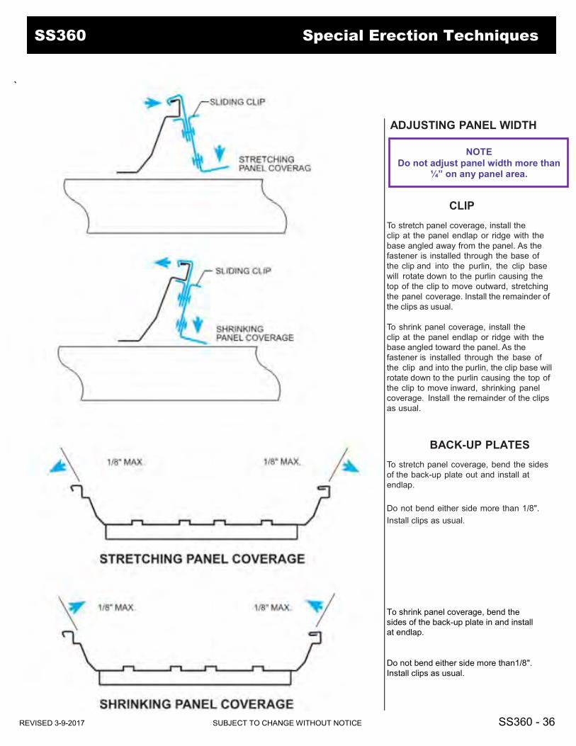
ADJUSTING PANEL WIDTH
CLIP To stretch panel coverage, install the clip at the panel endlap or ridge with the base angled away from the panel. As the fastener is installed through the base of the clip and into the purlin, the clip base will rotate down to the purlin causing the top of the clip to move outward, stretching the panel coverage. Install the remainder of the clips as usual. To shrink panel coverage, install the clip at the panel endlap or ridge with the base angled toward the panel. As the fastener is installed through the base of the clip and into the purlin, the clip base will rotate down to the purlin causing the top of the clip to move inward, shrinking panel coverage. Install the remainder of the clips as usual.
BACK-UP PLATES To stretch panel coverage, bend the sides of the back-up plate out and install at endlap. Do not bend either side more than 1/8". Install clips as usual. To shrink panel coverage, bend the sides of the back-up plate in and install at endlap. Do not bend either side more than1/8". Install clips as usual.
NOTE Do not adjust panel width more than
¼” on any panel area.
`
REVISED 3-9-2017 SUBJECT TO CHANGE WITHOUT NOTICE SS360 - 36 REVISED 2-10-2017 SUBJECT TO CHANGE WITHOUT NOTICE SS360 - 30 REVISED 7-26-2016 SUBJECT TO CHANGE WITHOUT NOTICE SS360 - 16
REVISED 7-26-2016 SUBJECT TO CHANGE WITHOUT NOTICE SS360 - 15
SS360 Special Erection Techniques


