Via Overnight Mail July 31, 2006 Subject: Special Service Campaign (SSC) 6LE Certain 2006 GS 300 2WD, GS 300 AWD and GS 430 Vehicles Electric Power Steering (EPS) Replacement Dear Dealer Principal: Lexus has initiated a Special Service Campaign (SSC) on certain 2006 GS 300 2WD, GS 300 AWD and GS 430 vehicles. Campaign details and the degree of your dealer’s involvement are explained below. Condition On certain 2006 model year Lexus GS 300 (both 2WD and AWD) and GS 430 vehicles, customers may experience a noticeable gradual increase in the steering effort necessary at low speeds when turning the steering wheel in the complete left or right position. This condition may be most perceptible when parking the vehicle. For further information refer to the attached Lexus Q&A and customer notification letter. Owner Notification Date Owner notification letters will be mailed in phases via First Class Mail beginning in early August 2006. Identification of Involved Vehicles Model Year VDS VIN Ranges BH96S 5002385 – 5005184 BN96S 5001092 – 5002302 2006 CH96S 0001906 – 0003062 Note: Not all vehicles in the VIN range are affected. As always, dealers should consult Dealer Daily or TIS to confirm VIN eligibility and to assure that the SSC is applicable. This will verify the vehicle is involved and has not already been completed prior to dealer shipment or by another dealer. TMS warranty will not reimburse dealers for repairs conducted on vehicles that are not affected or were completed by another dealer. Implementation at Dealerships The SSC package contains the repair instructions, warranty claim procedures, and parts order information. All associates who have a part in the completion of this campaign should be familiar with its contents.
Transcript
Via Overnight Mail July 31, 2006 Subject: Special Service Campaign (SSC) 6LE Certain 2006 GS 300 2WD, GS 300 AWD and GS 430 Vehicles Electric Power Steering (EPS) Replacement Dear Dealer Principal: Lexus has initiated a Special Service Campaign (SSC) on certain 2006 GS 300 2WD, GS 300 AWD and GS 430 vehicles. Campaign details and the degree of your dealer’s involvement are explained below. Condition On certain 2006 model year Lexus GS 300 (both 2WD and AWD) and GS 430 vehicles, customers may experience a noticeable gradual increase in the steering effort necessary at low speeds when turning the steering wheel in the complete left or right position. This condition may be most perceptible when parking the vehicle.
For further information refer to the attached Lexus Q&A and customer notification letter. Owner Notification Date Owner notification letters will be mailed in phases via First Class Mail beginning in early August 2006. Identification of Involved Vehicles
Model Year VDS VIN Ranges BH96S 5002385 – 5005184 BN96S 5001092 – 5002302
2006
CH96S 0001906 – 0003062 Note: Not all vehicles in the VIN range are affected. As always, dealers should consult Dealer Daily or TIS to confirm VIN eligibility and to assure that the SSC is applicable. This will verify the vehicle is involved and has not already been completed prior to dealer shipment or by another dealer. TMS warranty will not reimburse dealers for repairs conducted on vehicles that are not affected or were completed by another dealer. Implementation at Dealerships The SSC package contains the repair instructions, warranty claim procedures, and parts order information. All associates who have a part in the completion of this campaign should be familiar with its contents.
2
Replacement Parts
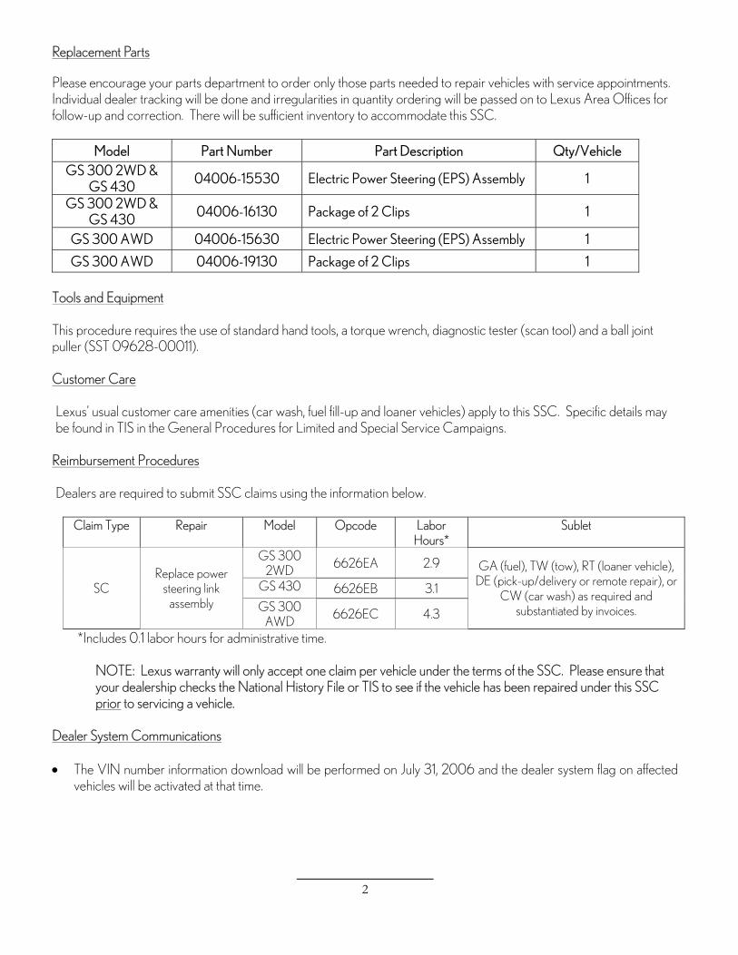
Please encourage your parts department to order only those parts needed to repair vehicles with service appointments. Individual dealer tracking will be done and irregularities in quantity ordering will be passed on to Lexus Area Offices for follow-up and correction. There will be sufficient inventory to accommodate this SSC.
Model Part Number Part Description Qty/Vehicle GS 300 2WD &
GS 430 04006-15530 Electric Power Steering (EPS) Assembly 1
GS 300 AWD 04006-15630 Electric Power Steering (EPS) Assembly 1
GS 300 AWD 04006-19130 Package of 2 Clips 1 Tools and Equipment This procedure requires the use of standard hand tools, a torque wrench, diagnostic tester (scan tool) and a ball joint puller (SST 09628-00011). Customer Care Lexus’ usual customer care amenities (car wash, fuel fill-up and loaner vehicles) apply to this SSC. Specific details may be found in TIS in the General Procedures for Limited and Special Service Campaigns.
Reimbursement Procedures Dealers are required to submit SSC claims using the information below.
Claim Type Repair Model Opcode Labor Hours*
Sublet
GS 300 2WD
6626EA 2.9
GS 430 6626EB 3.1 SC Replace power
steering link assembly GS 300
AWD 6626EC 4.3
GA (fuel), TW (tow), RT (loaner vehicle), DE (pick-up/delivery or remote repair), or
CW (car wash) as required and substantiated by invoices.
*Includes 0.1 labor hours for administrative time.
NOTE: Lexus warranty will only accept one claim per vehicle under the terms of the SSC. Please ensure that your dealership checks the National History File or TIS to see if the vehicle has been repaired under this SSC prior to servicing a vehicle.
Dealer System Communications • The VIN number information download will be performed on July 31, 2006 and the dealer system flag on affected
vehicles will be activated at that time.
3
• The operation code will be downloaded and available for dealerships to use on July 31, 2006. DMS dealer files are automatically updated and no further action should be required.
Thank you for your understanding. Your on-going care for these Lexus owners during this campaign protects our customers and their image of Lexus. Sincerely, Chuck Yaeger National Customer Services Field Operations Manager Attachments CC: Customer Satisfaction Manager General Manager Parts Manager Sales Manager Service Manager
4
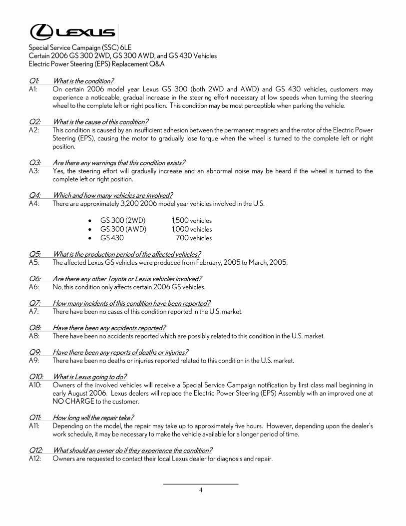
Special Service Campaign (SSC) 6LE Certain 2006 GS 300 2WD, GS 300 AWD, and GS 430 Vehicles Electric Power Steering (EPS) Replacement Q&A Q1: What is the condition? A1: On certain 2006 model year Lexus GS 300 (both 2WD and AWD) and GS 430 vehicles, customers may experience a noticeable, gradual increase in the steering effort necessary at low speeds when turning the steering wheel to the complete left or right position. This condition may be most perceptible when parking the vehicle. Q2: What is the cause of this condition? A2: This condition is caused by an insufficient adhesion between the permanent magnets and the rotor of the Electric Power Steering (EPS), causing the motor to gradually lose torque when the wheel is turned to the complete left or right position. Q3: Are there any warnings that this condition exists? A3: Yes, the steering effort will gradually increase and an abnormal noise may be heard if the wheel is turned to the complete left or right position. Q4: Which and how many vehicles are involved? A4: There are approximately 3,200 2006 model year vehicles involved in the U.S.
Q5: What is the production period of the affected vehicles? A5: The affected Lexus GS vehicles were produced from February, 2005 to March, 2005. Q6: Are there any other Toyota or Lexus vehicles involved? A6: No, this condition only affects certain 2006 GS vehicles. Q7: How many incidents of this condition have been reported? A7: There have been no cases of this condition reported in the U.S. market. Q8: Have there been any accidents reported? A8: There have been no accidents reported which are possibly related to this condition in the U.S. market. Q9: Have there been any reports of deaths or injuries? A9: There have been no deaths or injuries reported related to this condition in the U.S. market. Q10: What is Lexus going to do? A10: Owners of the involved vehicles will receive a Special Service Campaign notification by first class mail beginning in early August 2006. Lexus dealers will replace the Electric Power Steering (EPS) Assembly with an improved one at NO CHARGE to the customer. Q11: How long will the repair take? A11: Depending on the model, the repair may take up to approximately five hours. However, depending upon the dealer’s work schedule, it may be necessary to make the vehicle available for a longer period of time. Q12: What should an owner do if they experience the condition? A12: Owners are requested to contact their local Lexus dealer for diagnosis and repair.
5
Special Service Campaign 6LE
Certain 2006 GS 300 and GS 430 Vehicles Electric Power Steering (EPS) Replacement
Dear Lexus Owner:
Lexus is dedicated to the “Passionate Pursuit of Perfection.” Thank you very much for your patronage of Lexus. We are dedicated to providing vehicles of outstanding quality and value. As part of our continuing efforts to provide superior customer satisfaction, Lexus is announcing a Special Service Campaign Program on certain 2006 model year GS 300 and GS 430 vehicles. What is the condition?
On certain 2006 Model Year Lexus GS 300 and GS 430 vehicles, you may experience a noticeable gradual increase in the steering effort necessary at low speeds when turning the steering wheel to the complete left or right position. This condition may be most perceptible when parking your vehicle.
What is the cause of the condition?
This condition is caused by an insufficient adhesion between the permanent magnets and the rotor of the Electric Power Steering (EPS), causing the motor to gradually lose torque when the wheel is turned to the complete left or right position.
What will Lexus do?
Any Lexus dealer will replace the Electric Power Steering (EPS) at NO CHARGE to you.
What should you do?
Please contact your authorized Lexus dealer to schedule an appointment to replace the Electric Power Steering (EPS) with an improved one. Based upon your specific vehicle model, the repair may take up to approximately five hours. However, depending upon the dealer’s work schedule, it may be necessary to make your vehicle available for a longer period of time.
Please present this notice to the dealer when you bring the vehicle in for your service appointment. If you no longer own the vehicle, please indicate so on the enclosed postage-paid form, providing us with the name and address of the new owner if possible.
What if you have other questions?
Please contact any Lexus dealer or call the Lexus Customer Assistance Center at 1-800-255-3987 Monday through Friday, 5:00 am to 9:30 pm, Saturday and Sunday 7:00 am through 3:00 pm Pacific Standard Time.
We have sent this notice in the interest of your continued satisfaction with our products, and we sincerely regret any inconveniences this condition may have caused you. Thank you for driving a Lexus. Sincerely,
LEXUS DIVISION TOYOTA MOTOR SALES, U.S.A., INC.
6
TECHNICAL INSTRUCTIONS
FOR
SPECIAL SERVICE CAMPAIGN 6LE
2006 GS ELECTRIC POWER STEERING (EPS) REPLACEMENT
7
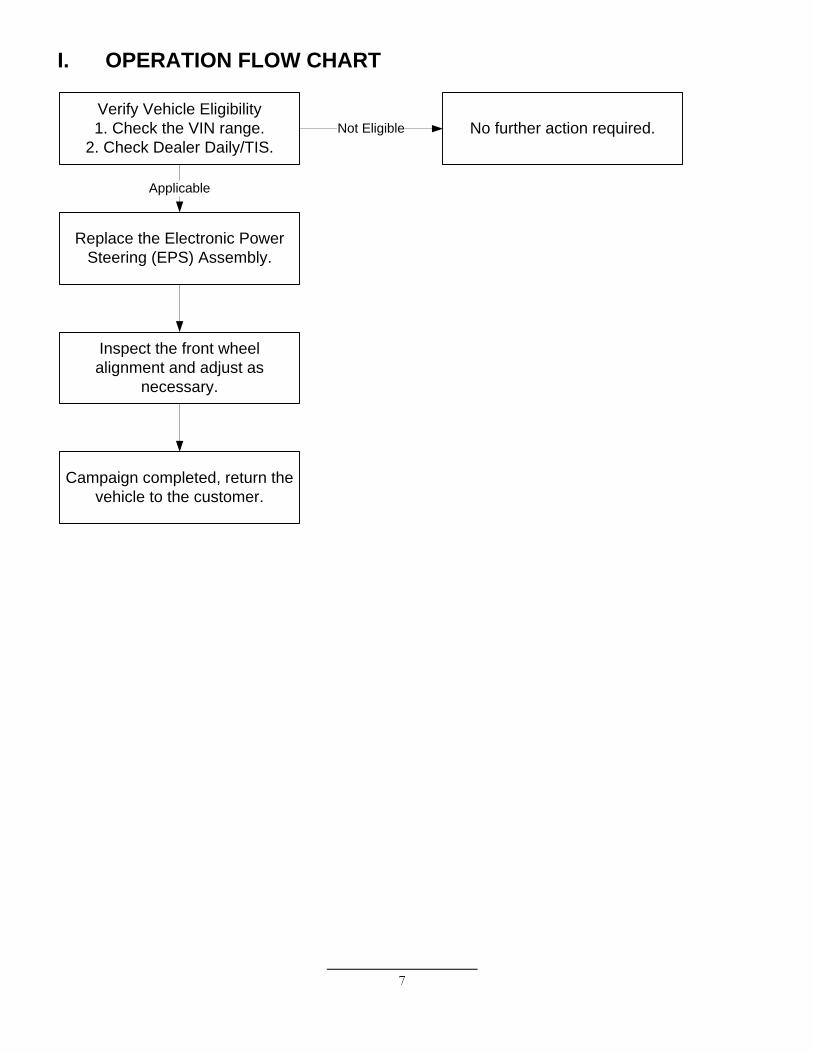
I. OPERATION FLOW CHART
Verify Vehicle Eligibility1. Check the VIN range.
2. Check Dealer Daily/TIS.No further action required.Not Eligible
Applicable
Campaign completed, return the vehicle to the customer.
Replace the Electronic Power Steering (EPS) Assembly.
Inspect the front wheel alignment and adjust as
necessary.
8
II. IDENTIFICATION OF AFFECTED VEHICLES A. AFFECTED VIN RANGE
Model Part Number Part Description Qty. GS 300 2WD
or GS 430 04006-15530 Electric Power Steering (EPS) Assembly 1
GS 300 2WD or GS 430 04006-16130 Package of 2 Clips 1
Model Part Number Part Description Qty.
GS 300 AWD 04006-15630 Electric Power Steering (EPS) Assembly 1 GS 300 AWD 04006-19130 Package of 2 Clips 1
B. TOOLS
• Standard hand tools • Torque Wrench • Diagnostic Tester (Scan Tool) • SST 09628-00011 (Ball Joint Puller)
C. EQUIPMENT
• Transmission Jack * • Under-Hoist Stand *
D. MATERIALS
a. Wooden Block (x2)*
* For Electric Power Steering (EPS) replacement on AWD vehicles only.
9
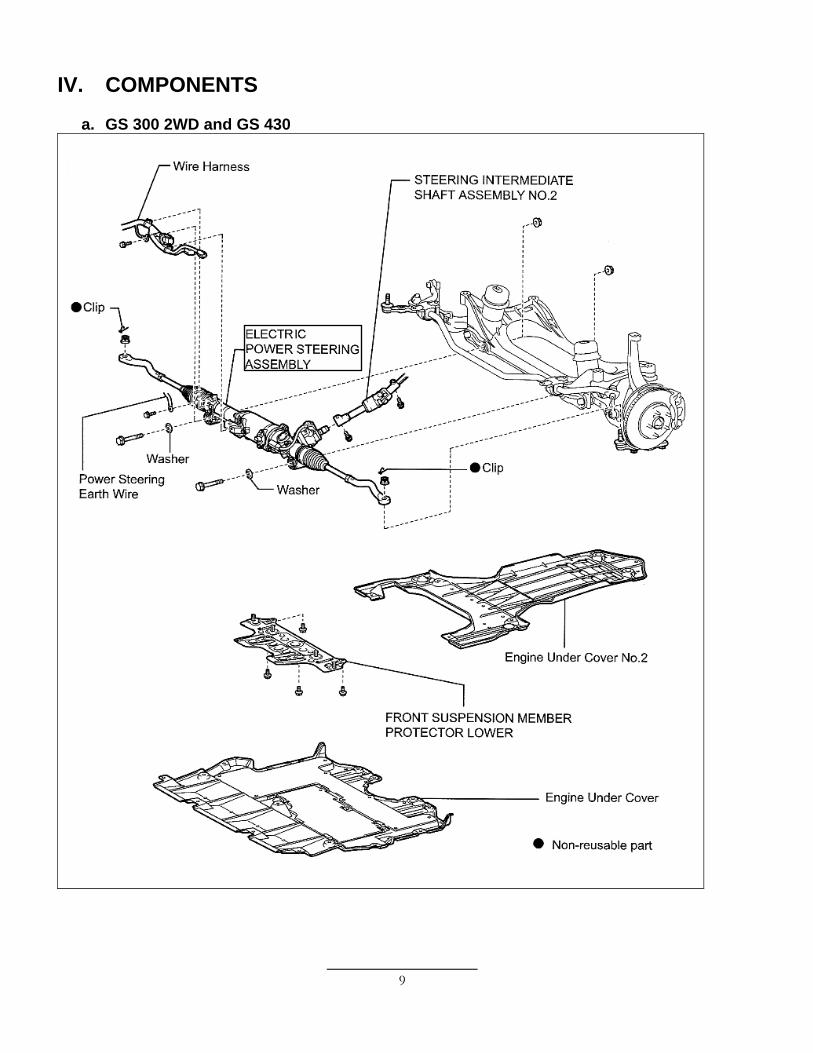
IV. COMPONENTS
a. GS 300 2WD and GS 430
10
[Components Continued…]
b. GS 300 AWD
11
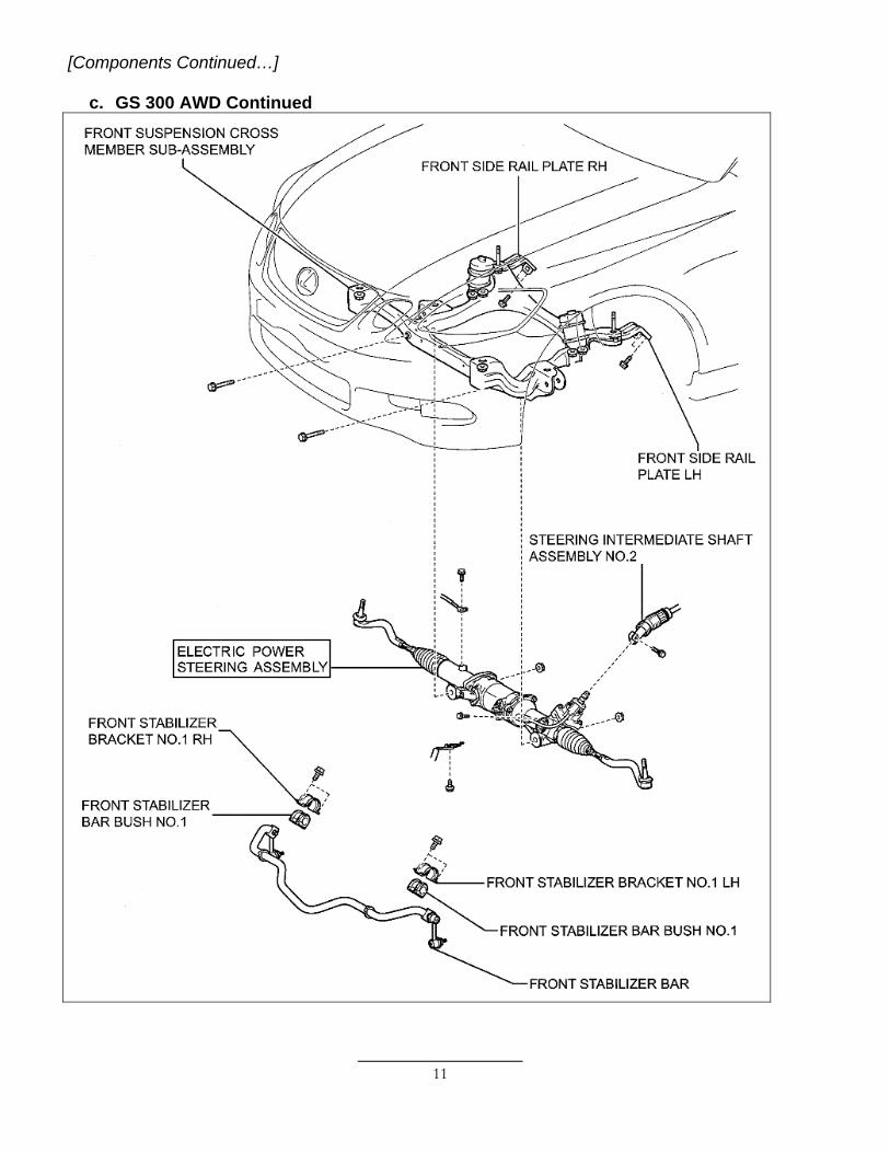
[Components Continued…] c. GS 300 AWD Continued
12
V. BACKGROUND On certain 2006 Model Year Lexus GS 300 (both 2WD and AWD) and GS 430 vehicles, customers may experience a noticeable gradual increase in the steering effort necessary at low speeds when turning the steering wheel to the complete left or right position. This condition may be most perceptible when parking the vehicle. VI. SERVICE PRECAUTIONS
A. ROTATION ANGLE SENSOR, TORQUE SENSOR ZERO POINT, AND VARIABLE GEAR RATIO STEERING (VGRS) SYSTEM CALIBRATIONS
After Electric Power Steering Assembly replacement and front wheel alignment, the following procedures must be performed…
• Clearing of the rotation angle sensor calibration value • Initialization of the rotation angle sensor • Calibration of the torque sensor zero point • Calibration of the VGRS actuator angle (GS 430 Vehicles Only) • Neutral calibration of the VGRS actuator angle (GS 430 Vehicles Only)
B. CLEARANCE SONAR, POWER WINDOW CONTROL, SLIDING ROOF
AND VARIABLE GEAR RATIO STEERING (VGRS) SYSTEM INITIALIZATION
When disconnecting then reconnecting the battery,the following systems must be initialized…
• Clearance Sonar System • Power Window Control System • Sliding Roof System • VGRS System (GS 430 Vehicles Only)
13
• For GS 300 2WD & GS 430 vehicles, please reference the “VII.
WORK PROCEDURE FOR GS 300 2WD & GS 430 VEHICLES” listed below on this page.
• For GS 300 AWD vehicles, please reference the “VIII.
WORK PROCEDURE FOR GS 300 AWD VEHICLES” on page 16.
VII. WORK PROCEDURE FOR GS 300 2WD & GS 430 VEHICLES A. REMOVE THE ELECTRIC POWER STEERING (EPS) ASSEMBLY
1. RECORD THE RADIO STATION
PRESETS
2. PLACE THE FRONT WHEELS IN A STRAIGHT-AHEAD POSITION
a) Place the front wheels in a straight-
ahead position and center the steering wheel.
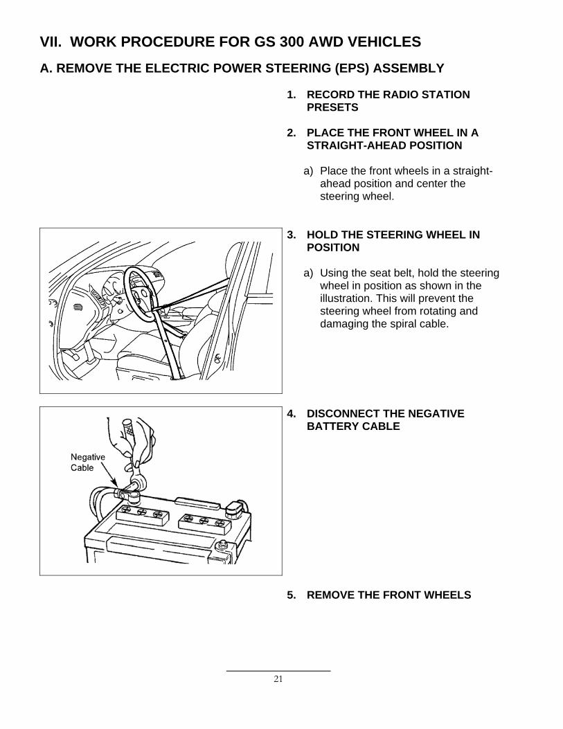
3. HOLD THE STEERING WHEEL IN POSITION
a) Using the seat belt, hold the steering
wheel in position as shown in the illustration. This will prevent the steering wheel from rotating and damaging the spiral cable.
14
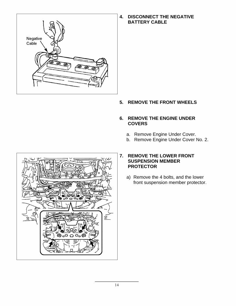
4. DISCONNECT THE NEGATIVE BATTERY CABLE
5. REMOVE THE FRONT WHEELS
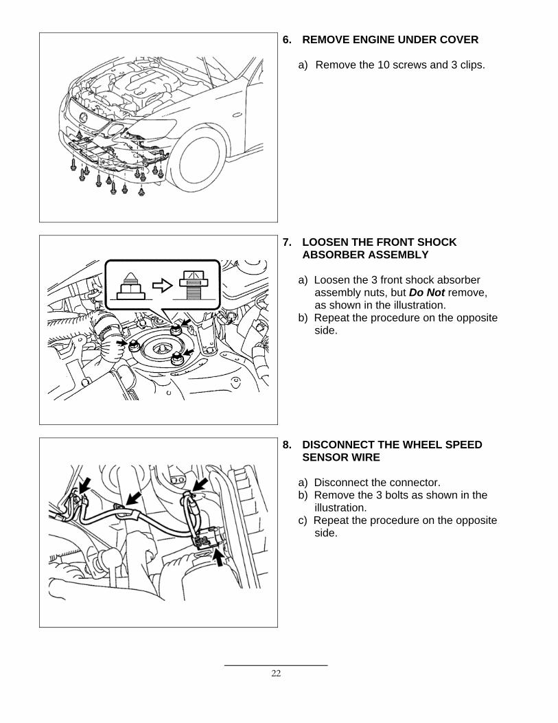
6. REMOVE THE ENGINE UNDER COVERS
a. Remove Engine Under Cover. b. Remove Engine Under Cover No. 2.
7. REMOVE THE LOWER FRONT SUSPENSION MEMBER PROTECTOR
a) Remove the 4 bolts, and the lower
front suspension member protector.
15
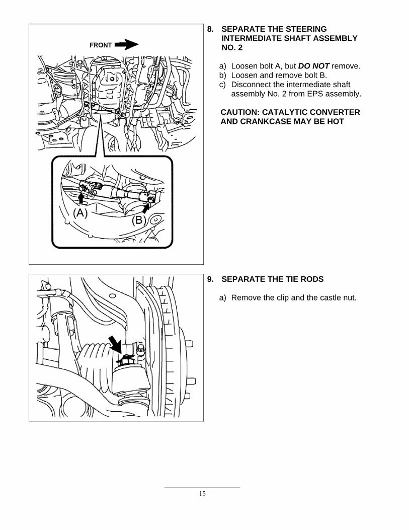
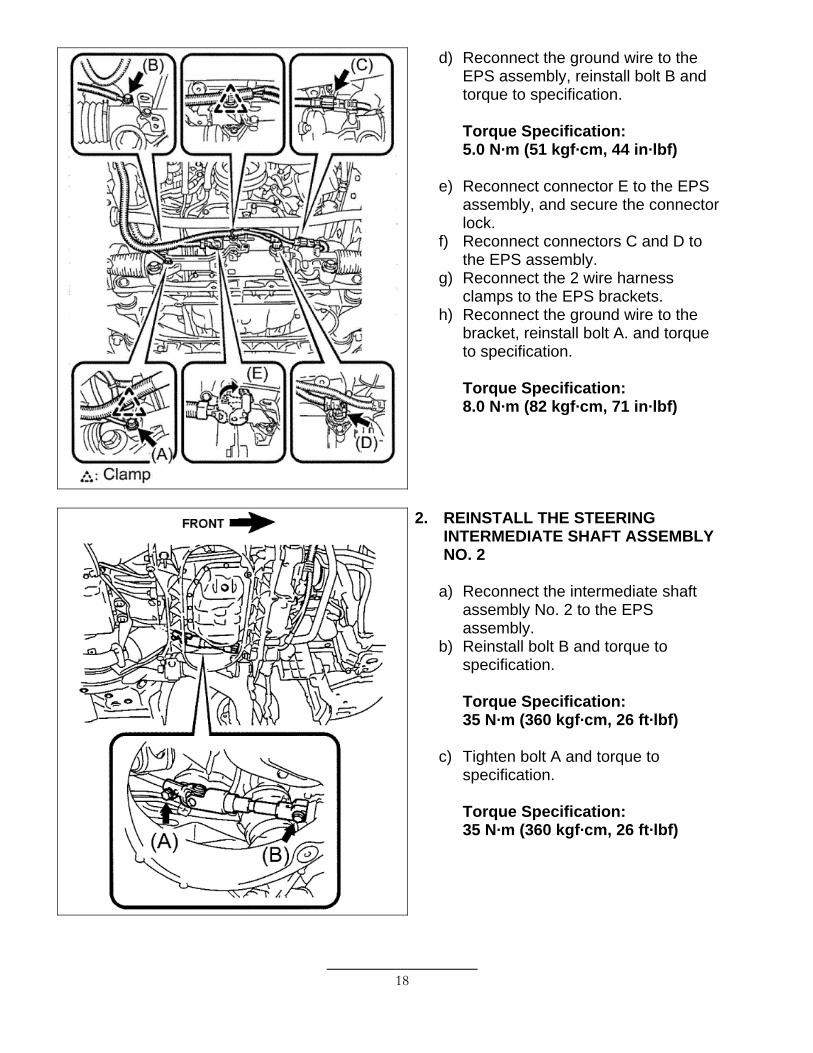
8. SEPARATE THE STEERING INTERMEDIATE SHAFT ASSEMBLY NO. 2
a) Loosen bolt A, but DO NOT remove. b) Loosen and remove bolt B. c) Disconnect the intermediate shaft
assembly No. 2 from EPS assembly.
CAUTION: CATALYTIC CONVERTER AND CRANKCASE MAY BE HOT
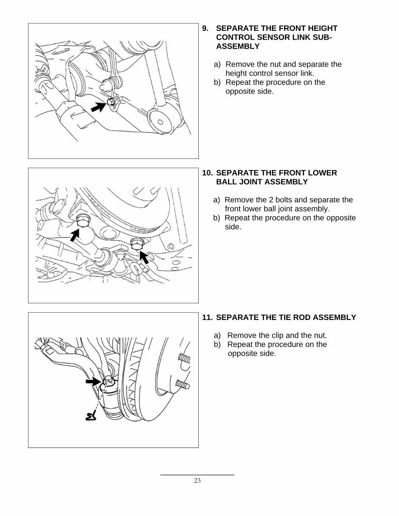
9. SEPARATE THE TIE RODS
a) Remove the clip and the castle nut.
16
b) Using SST 09628-00011, separate the tie rod from the steering knuckle.
c) Repeat the procedure on the opposite side.
SST: 09628-00011 NOTE: • Hang the SST with the
attached string to prevent it from falling.
• DO NOT damage the front brake disc dust cover.
• DO NOT damage the ball joint dust boot.
• DO NOT damage the steering knuckle.
10. REMOVE THE EPS ASSEMBLY
a) Remove bolt A to disconnect the ground wire from the bracket.
b) Disconnect the 2 wire harness clamps from the EPS brackets.
c) Disconnect connectors C and D from the EPS assembly.
d) Release the connector lock and disconnect connector E from the EPS assembly.
e) Remove bolt B to disconnect the ground wire from the EPS assembly.
17
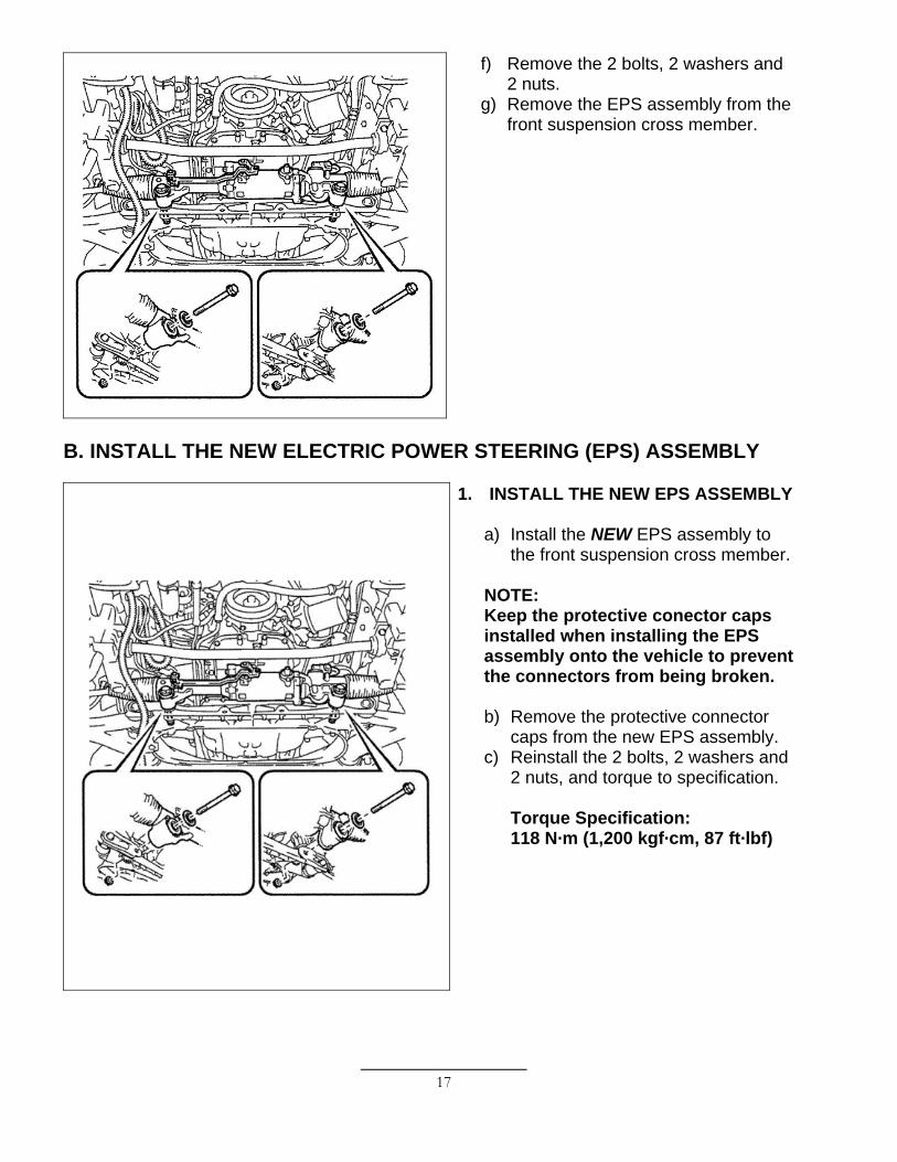
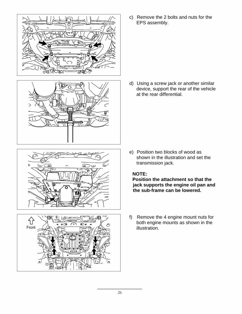
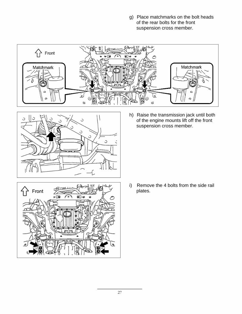
f) Remove the 2 bolts, 2 washers and 2 nuts.
g) Remove the EPS assembly from the front suspension cross member.
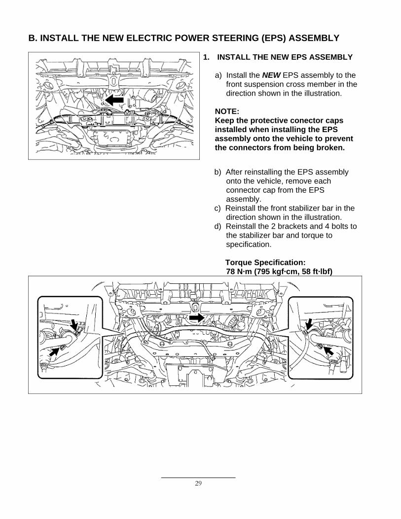
B. INSTALL THE NEW ELECTRIC POWER STEERING (EPS) ASSEMBLY
1. INSTALL THE NEW EPS ASSEMBLY
a) Install the NEW EPS assembly to the front suspension cross member.
NOTE: Keep the protective conector caps installed when installing the EPS assembly onto the vehicle to prevent the connectors from being broken.
b) Remove the protective connector
caps from the new EPS assembly. c) Reinstall the 2 bolts, 2 washers and
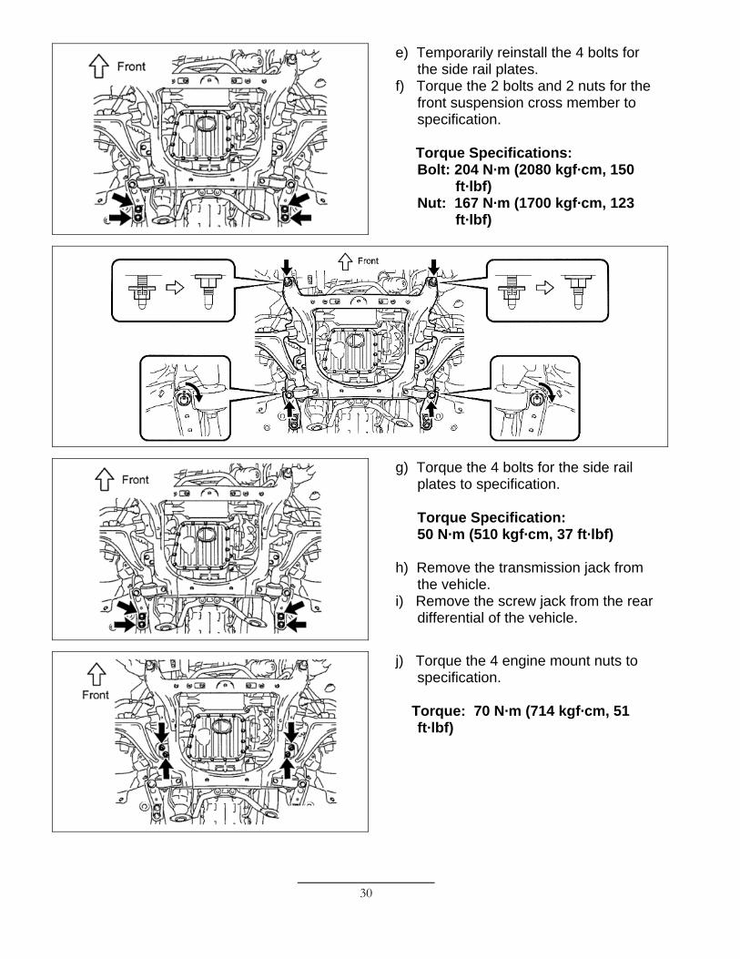
Torque Specification: 65 N·m (663 kgf·cm, 50 ft·lbf) NOTE: If the holes for the clip are not aligned, the nut can be tightened up to an additional 60º.
b) Install a NEW clip. c) Repeat the procedure on the opposite
side.
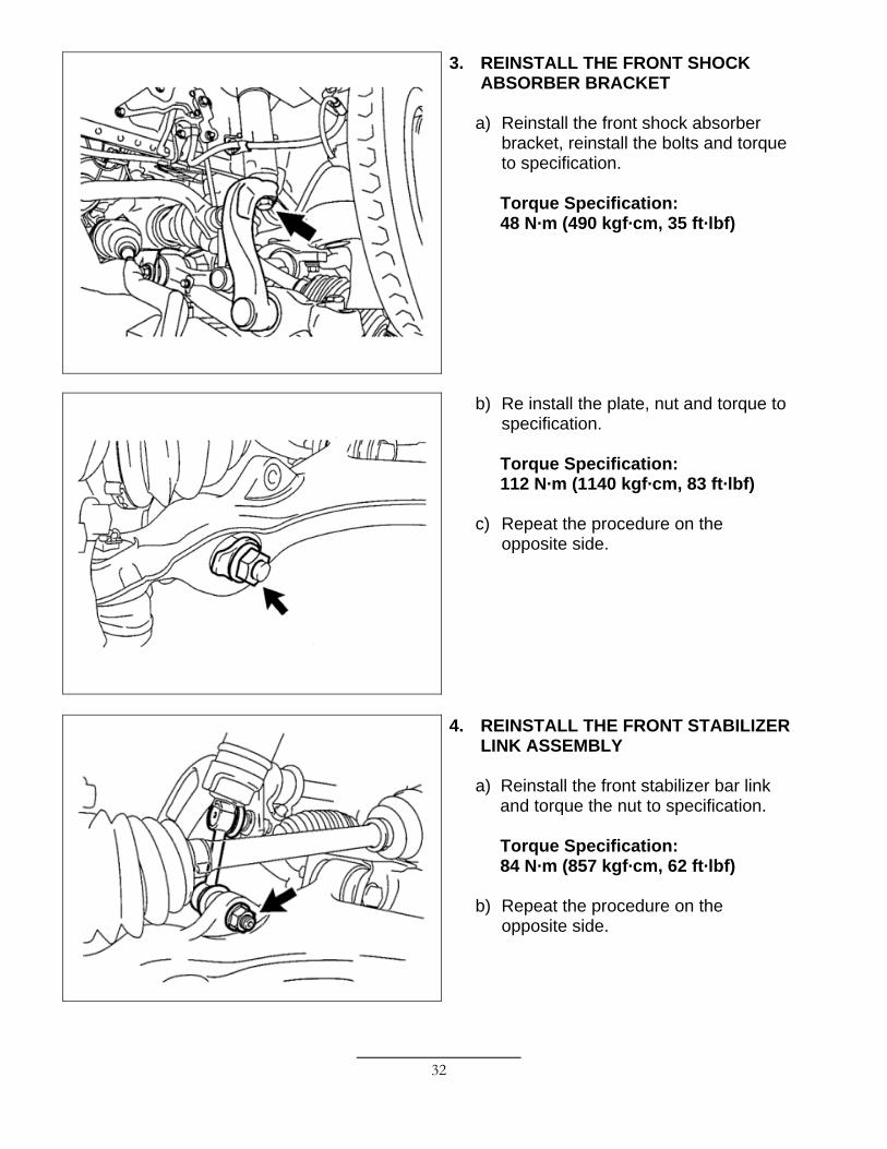
6. REINSTALL THE FRONT LOWER
BALL JOINT ASSEMBLY
a) Reinstall the front lower ball joint assembly, the 2 bolts, and torque to specification.
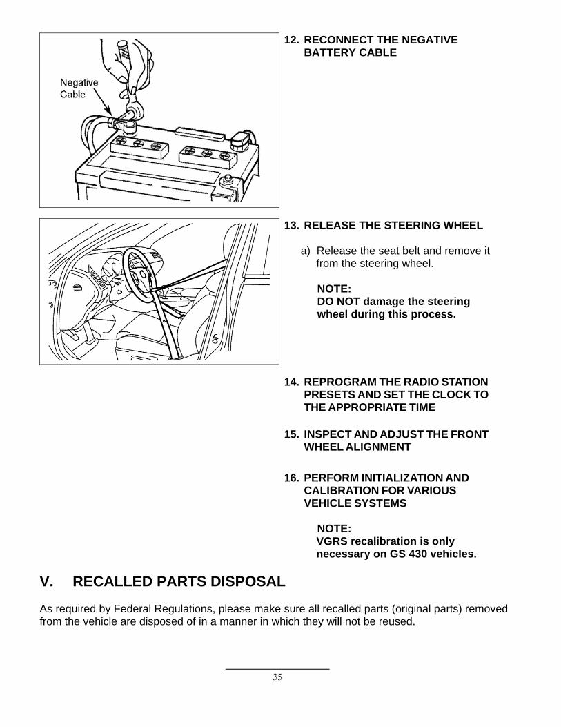
a) Release the seat belt and remove it from the steering wheel.
NOTE: DO NOT damage the steering wheel during this process.
14. REPROGRAM THE RADIO STATION
PRESETS AND SET THE CLOCK TO THE APPROPRIATE TIME
15. INSPECT AND ADJUST THE FRONT
WHEEL ALIGNMENT 16. PERFORM INITIALIZATION AND
CALIBRATION FOR VARIOUS VEHICLE SYSTEMS
NOTE: VGRS recalibration is only necessary on GS 430 vehicles.
V. RECALLED PARTS DISPOSAL As required by Federal Regulations, please make sure all recalled parts (original parts) removed from the vehicle are disposed of in a manner in which they will not be reused.