McIntosh, Dawn 1 34 th Annual Small Satellite Conference SSC20-WKVII-02 The NASA Cubesat Missions Flying on Artemis-1 Dawn M. McIntosh NASA Ames Research Center N269-3, Moffett Field, CA 94035; 650-604-0157 [email protected]John D. Baker NASA Jet Propulsion Laboratory 4800 Oak Grove Drive, Pasadena, CA 91109; 818-354-5004 [email protected]Joseph A. Matus NASA Marshall Spaceflight Center ST24, Huntsville, AL 35812; 256-544-8089 [email protected]ABSTRACT In 2021, the Space Launch Services (SLS) Artemis-1 mission will carry thirteen 6U CubeSats into deep space. Three of those payloads are NASA missions performing a variety of unique deep-space science experiments. The three NASA CubeSat missions are BioSentinel, Lunar Flashlight and NEA Scout. The BioSentinel mission will measure deep-space radiation effects on DNA using yeast organisms. It is a six-month mission in a heliocentric orbit. BioSentinel was designed, built, tested and operated out of NASA Ames Research Center. Lunar Flashlight’s mission is to look for surface water ice in the permanently shadowed regions near the south pole of the Moon and test out new small spacecraft technologies. The spacecraft was developed at the Jet Propulsion Laboratory as a technology demonstration mission with support from the Marshall Space Flight Center, the Goddard Space Flight Center and Georgia Institute of Technology. NEA Scout’s mission is twofold: to demonstrate solar sail deployment and spacecraft navigation using the sail to detect, track, fly by, and characterize a near earth asteroid. NEA Scout was developed by NASA’s Marshall Space Flight Center in partnership with the Jet Propulsion Laboratory, and support from the Goddard Space Flight Center, Lyndon B. Johnson Space Center, and Langley Research Center. NASA ARTEMIS-1 MISSIONS OVERVIEW In an effort to increase the scientific and exploration capability of the Space Launch System (SLS), the National Aeronautics and Space Administration (NASA) Exploration Systems Development (ESD) Program directed the SLS Program to accommodate Secondary Payloads on a non-interference, no harm basis. Each payload is a 6U CubeSat class payload. The SLS Artemis-1 vehicle, Figure 1, will launch thirteen of these CubeSat payloads.
Transcript
McIntosh, Dawn 1 34th Annual Small Satellite Conference
SSC20-WKVII-02 The NASA Cubesat Missions Flying on Artemis-1
ABSTRACT In 2021, the Space Launch Services (SLS) Artemis-1 mission will carry thirteen 6U CubeSats into deep space. Three of those payloads are NASA missions performing a variety of unique deep-space science experiments. The three NASA CubeSat missions are BioSentinel, Lunar Flashlight and NEA Scout. The BioSentinel mission will measure deep-space radiation effects on DNA using yeast organisms. It is a six-month mission in a heliocentric orbit. BioSentinel was designed, built, tested and operated out of NASA Ames Research Center. Lunar Flashlight’s mission is to look for surface water ice in the permanently shadowed regions near the south pole of the Moon and test out new small spacecraft technologies. The spacecraft was developed at the Jet Propulsion Laboratory as a technology demonstration mission with support from the Marshall Space Flight Center, the Goddard Space Flight Center and Georgia Institute of Technology. NEA Scout’s mission is twofold: to demonstrate solar sail deployment and spacecraft navigation using the sail to detect, track, fly by, and characterize a near earth asteroid. NEA Scout was developed by NASA’s Marshall Space Flight Center in partnership with the Jet Propulsion Laboratory, and support from the Goddard Space Flight Center, Lyndon B. Johnson Space Center, and Langley Research Center.
NASA ARTEMIS-1 MISSIONS OVERVIEW In an effort to increase the scientific and exploration capability of the Space Launch System (SLS), the National Aeronautics and Space Administration (NASA) Exploration Systems Development (ESD) Program directed the SLS Program to accommodate Secondary Payloads on a non-interference, no harm basis. Each payload is a 6U CubeSat class payload. The SLS Artemis-1 vehicle, Figure 1, will launch thirteen of these CubeSat payloads.
McIntosh, Dawn 2 34th Annual Small Satellite Conference
Figure 1: SLS Artemis I
The decision was made based on the large support base across NASA, other government agencies, and the international community for access to much higher orbits than are currently available for small payloads. NASA is providing three of those payloads.: • BioSentinel • Lunar Flashlight • NEA Scout
Artemis-1 The primary mission of Artemis-1 is to send the unmanned Orion Crew Vehicle on a test flight to the cis-lunar region and then return to Earth. The mission begins with the launch of the Space Launch System (SLS) Vehicle at NASA KSC Launch Pad 39B. After the Orion Multi-Purpose Crew Vehicle (MPCV) separates from the Core Stage, the Interim Cryogenic Propulsion Stage (ICPS), where the secondary payloads are located, prepares for the disposal maneuver. Its last act is to send a discrete signal to activate the Secondary Payloads Deployment System (SPDS) Sequencer and start the countdown to deployment of the secondary payloads. The secondary payloads are scheduled for deployment at a series of trajectory locations known as “bus stops.”
BIOSENTINEL
Introduction BioSentinel is an NPR 7120.5 Category III Class D project. The spacecraft bus and one of the two payloads were designed, developed, assembled, integrated and tested at NASA Ames Research Center. Mission Operations will also be performed at NASA Ames Research Center.
BioSentinel is using a combination of: In-House Technical Expertise, Small Business Innovation Research (SBIR) and heritage flight hardware & software to support mission objectives: • BioSensor Payload was designed and developed by
Ames Research Center, leveraging over a decade of in-house microfluidics and biology flight experimentation conducted using Nano-satellites.
• BioSentinel EPS Subsystem leveraged Ames Research Center in-house expertise for Nano-satellite bus development.
• BioSentinel Flight Software leveraged, core flight software, with heritage developed and flown on the Lunar Atmosphere Dust Environment Explorer (LADEE) mission.
• Spacecraft ADCS, Propulsion and Solar Array Subsystems leveraged industry SBIR development approach.
• Spacecraft Command and Data Handling Subsystem leveraged COTS designs.
• Communication Subsystem, IRIS Radio and antenna’s leveraged JPL’s MarCO heritage design.
• Linear Energy Transfer (LET) Spectrometer Payload was provided by NASA JSC RadWorks.
Science Goals BioSentinel will pave the way for future studies of the biological effects of the complex radiation environment of outer space. Using a “radiation biosensor” strategy in which the model organism Saccharomyces cerevisiae (budding or brewer’s yeast) reports the occurrence and repair of DNA damage via the exponential amplification of cells in culture, statistically meaningful rates of this human-relevant damage-and-repair process are measured vs. radiation dose for a minimum of 6 months. In the heliocentric science orbit, BioSentinel will receive daily radiation doses relevant to space travel, which will be measured by an onboard physical dosimeter, the LET Spectrometer, providing a frame of reference for the biological response. Overall, BioSentinel addresses the critical question of how life responds to the space radiation environment beyond the Earth’s magnetosphere; it emphasizes genetic and cellular responses, using a well-characterized cellular model organism exposed to deep space radiation.
McIntosh, Dawn 3 34th Annual Small Satellite Conference
Ionizing radiation presents a major challenge to human exploration and long-term residence in space. In humans, most long-term effects of radiation damage (e.g., cancers) are due to DNA damage. The deep space radiation spectrum includes highly ionizing particles (galactic and solar cosmic rays and high-energy protons) that can generate a variety of lesions in DNA, including the highly deleterious double strand breaks (DSBs). While progress identifying and characterizing biological radiation effects using Earth-based proton and heavy-ion radiation facilities has been significant, no terrestrial source duplicates the full energy spectrum, particle diversity, and long-term, low-dose-rate space radiation environment. Thus, critical gaps exist in our knowledge of the biological effects of space radiation, which are not addressed by terrestrial experiments.
BioSentinel uses budding yeast cells as biosensors to measure DNA damage in response to ambient space radiation, calibrating ground data with the results. Even though ionizing radiation can generate a variety of DNA lesions (directly or indirectly) and can significantly impair cellular pathways and organelle function, our current experimental design allows us to screen for unrepairable DNA damage using a DNA repair defective mutant and wild type strains. DNA lesions induced by ionizing radiation and their subsequent repair exhibit striking conservation from yeast to humans. Though yeast is a eukaryotic cell and similar to human cells, the importance of using the yeast cell here is not predicated solely on its similarity to human cells but rather to it being a well-characterized system for radiation studies, particularly for DNA damage response. Therefore, even though the radiation sensitivities of all living systems are unique and are determined by cell structure, size, tissue organization, and DNA content, yeast is used for direct comparisons of biological effects in space versus the ground to help predict the severity of radiation damage in other organisms.
In BioSentinel, each of the yeast strains is carried in multiple independent culture wells, sets of which are activated at different time points over the 6-month mission. The instruments monitor each set of culture wells continuously before the next set of wells are activated, tracking cell growth via optical density and metabolic activity using a viability dye. The anticipated orbit plus a spacecraft designed for minimal shielding of the cells will provide biologically significant radiation doses.
Payload Details The BioSentinel spacecraft, see Figure 2, allocates a 4U volume to the two independent and complementary payloads: The BioSensor payload and the Linear
Energy Transfer (LET) spectrometer payload. Together these payloads comprise BioSentinel’s radiobiological experiment. Inside the BioSensor, the radiobiological experiment utilizes multiple independently activated sets of 16 microfluidically serviced microwells to monitor a variety of lesions in DNA, including the highly deleterious double-strand breaks, comparing their impact on the viability of the radiation-sensitized mutant to the self-repair-competent wild-type yeast. This is accomplished by optically monitoring the growth and metabolic activity of multiple microwell-contained cultures, generally one card, or 16 microwells each of wild-type and rad51D mutant per measurement time point. Simultaneously the LET payload spectrometer board records the passage of each high-energy particle as a track of pixels with accumulated charge and monitors total ionizing dose (TID). The associated control-and-measurement electronics and software reports radiation over the 0.2 to 300 keV/mm LET range, allowing the science team to study the effects of the measured radiation environment on the biology over the course of the mission.
The BioSentinel BioSensor payload is designed to use budding yeast Saccharomyces cerevisiae to measure the DNA damage response to ambient space radiation. The BioSensor payload will carry two strains of yeast. The first is a wild type that is radiation tolerant, the second is a mutant strain that is deficient in a gene that allows DNA repair following damage. Both strains used in the BioSentinel BioSensor are classified as Biosafety level 1 organisms, as defined by the Center for Disease Control and Prevention, “Biosafety in Microbiological and Biomedical Laboratories” (BMBL) 5th Edition. As the lowest of the four, Biosafety level 1 applies to laboratory settings in which personnel work with low-risk microbes that pose little to no threat of infection in healthy adults.
Figure 2: BioSentinel General System Configuration - Exploded View
The yeast cells are stored in small cards with 16 microfluidic wells. A laboratory version of a single card
McIntosh, Dawn 4 34th Annual Small Satellite Conference
is shown in Figure 3. In a laboratory clean hood, yeast cells are placed in each of the card wells, allowed to dry and then sealed. Each well is approximately 2.5 mm in diameter and 10 mm in depth yielding around 100 microliters of volume. The card body itself is fabricated from clear polycarbonate.
Figure 3: BioSensor Microfluidic Card Each flight card is fabricated from a number of layers in addition to the polycarbonate body. An exploded view of the card is shown in Figure 4. The orange layer is a printed circuit board with three colors of LED lights for each well (570 nm, 630 nm, 850 nm). The transparent orange layer is a Kapton strip heater used to maintain the card temperature within either the storage (4 °C) or active growth (23 °C) temperatures for the yeast. Below this lays a thin layer of polycarbonate (in green), into which microfluidic channels are die cut. A thin layer of porous polycarbonate (in pink) acts as a filter, trapping the yeast cells within the center well and preventing their migration into the rest of the payload. The bottom printed circuit board contains a number of light sensitive detectors that convert the detected light intensity to frequency that is sampled by the payload electronics. A rendering of an assembled card is also shown in Figure 4. Each card is approximately 30 mm x 30 mm x 20 mm fully assembled and weighs ~50 grams.
Figure 4: Assembled & Exploded View of 4x4 BioSensor Card
The BioSensor payload has a total of 18 microfluidic cards resulting in 288 microwells to provide sufficient statistical signal over the lifetime of the mission. The BioSensor contains two banks of 9 4x4µwell cards. A single bank is shown in Figure 5. Each bank has two PCBs (also FR4) that contain readout multiplexers, drive multiplexers, pump drivers, and valve control circuitry. A small calibration cell is used to validate fluid state before flowing into the BioSensor payload.
McIntosh, Dawn 5 34th Annual Small Satellite Conference
The calibration cell is essentially a 4x4µwell card with only one microwell without yeast cells. The microfluidic cards are joined in a fused polycarbonate manifold and are positively attached using #0-80 fasteners to helicoils in the manifold. Small viton gaskets are used in assembly to seal the microfluidic channels. Small latching valves are used to control fluid flow within the manifold.
Figure 5: Photo of 9-Microfluidic Cards with a Cal Cell and Manifold
The two banks of cards are installed separately into a mechanical housing. The housing is fabricated of 7075-T651 machined aluminum. Two end caps are also made of 7075-T651 aluminum and are fixed with a number of #2-56 fasteners. Viton gaskets are used to seal the container. This design is based off the PharmaSat, O/OREOS and SporeSat payload canisters.
The BioSentinel design minimized the shielding for the biological payload to maximize radiation effects while providing radiation protection for the electronics. Details on spacecraft and payload design, material selection and thickness, subsystem components, etc. were worked by the team in order to meet science requirements.
Mission Description The BioSentinel Mission is slated to fly as a secondary payload on the Space Launch System’s (SLS’s) first mission, Artemis-1. When the BioSentinel spacecraft, depicted in Figure 6, is deployed, its trajectory will also be a lunar flyby into a similar orbit. The nominal trajectory puts BioSentinel into a heliocentric orbit where its distance to the sun is slightly closer than the Earth varying between 0.99 to 0.92 AU. The distance from BioSentinel to Earth continues to grow over the mission duration and becomes a driver for the spacecraft telecommunication subsystem, by the end of
the Mission the BioSentinel spacecraft is estimated to be at a maximum distance of 0.30-0.35 AU from Earth.
Figure 6: BioSentinel Spacecraft The nominal science mission planned for 6 months, over which time BioSentinel will complete a half revolution around the sun. An identical payload will also be used to conduct a comparison experiment in the microgravity environment of the International Space Station (ISS) to compare with the ground-based data and with deep space measurements to yield a relative calibration of the biological effects of radiation in each of these environments.
In order to better understand the biological response in different radiation environments, it will be critical to compare the results obtained in deep space to: (a) physically measured radiation dose, (b) results of studies conducted in terrestrial radiation facilities, and (c) models of expected DNA damage-and-repair rates. The same payload will also be flown on the International Space Station (ISS) to provide an additional reference frame for the biological effects of a more benign radiation environment with very similar microgravity conditions and to compare with other DNA damage data that have already been collected at this Low Earth Orbit (LEO). Delayed synchronous ground control investigations will also be performed using copies of the payloads and the same yeast strains. The thermal environment will be replicated using information from the free flyer and ISS payload temperature sensors, and a rotisserie system will be used to prevent yeast sedimentation after fluidic card activation on the ground. We hypothesize that, due to the unique composition, flux, and energy distribution of deep space radiation, radiation-induced responses in space will differ from ground-based and LEO (ISS) results. Whatever the outcome, the results will be critical to improve the interpretation of the biological effects of ionizing radiation exposure in deep space.
A mission that compares the biological effects of space radiation to Earth-based studies is essential prior to long-term human exploration. It is likely that the development of the radiation BioSensor capability proposed here will be utilized in future manned missions to the Moon, Near Earth Asteroids (NEAs),
McIntosh, Dawn 6 34th Annual Small Satellite Conference
and Mars for evaluation of the long-term biological effects of deep space radiation. Additionally, simple BioSensors can provide essential data for optimization of shielding strategies and potential countermeasure development for deep space exploration.
BioSentinel’s Mission will involve 6 distinct phases:
1. Initialization – BioSentinel will be deployed to a trans-lunar orbit by the SLS vehicle, and released from a PSC CSD, onboard the secondary stage at ‘Bus Stop 1’. It will detumble using onboard cold gas thrusters and maintain the IPCS lunar swing-by trajectory for a heliocentric orbit. The BioSentinel Spacecraft will remain in ‘Safe-Mode’ until contacted from the ground station.
2. Acquisition – Approximately 76 minutes from deployment, BioSentinel begins automated duty cycling of the IRIS Radio, transitioning to transmit mode for 20 minutes, and repeated every 73 minutes in an effort to establish communication with the ground station.
3. Initial Check-Out – After communication is established, BioSentinel will begin executing scheduled communication passes using the MGA for higher data rates. During this period, the spacecraft is evaluated for nominal health and status of on board systems. At the end of ‘Initial Check-Out’ the spacecraft will thermally condition itself for lunar swing-by and potential eclipse, to preserve the onboard biology.
4. Final Check-Out – After lunar swing-by the tri-fold solar arrays will be deployed. Final spacecraft & payload system checks will be completed to ready the spacecraft for science operations.
5. Science – During nominal science operations, the spacecraft will execute the pre-planned science experiment, acquire the science data from the payloads and relay the data to the Science Operation Center at Ames Research Center. The science phase of the mission comprises the bulk of the mission duration, with the mission experiment timeline shown in Figure 7.
6. Decommissioning – BioSentinel will downlink all remaining prioritized Science Data, and verify disposal trajectory prior to terminating the mission.
Figure 7: Timeline for Experiment Initiation and Growth of Yeast Cells During Flight
LUNAR FLASHLIGHT
Science Objectives
Lunar Flashlight’s mission is to look for surface frost / water ice in the permanently shadowed regions near the south pole the Moon. Measurements from LRO and other missions strongly indicate the presence of water ice on or near the surface in the PSRs, however, to date water has not been directly detected at the Moon, only by inference from the detection of hydroxyls (OH). One challenge is to differentiate water ice from dry regolith and other possible volatile compounds that may be found. As such, the lasers on Lunar Flashlight are spectrally tuned to detect both regolith and side bands for water ice at 1.5 µm and 2µm. The ratio of the first two lasers and the second two lasers will be used to differentiate regolith and also other potential volatiles on the lunar surface from surface frost.
Payload Details Lunar Flashlight’s payload consists of two separate subsystems: The Lunar Radiometer (LR) and the Laser Projector (LP).
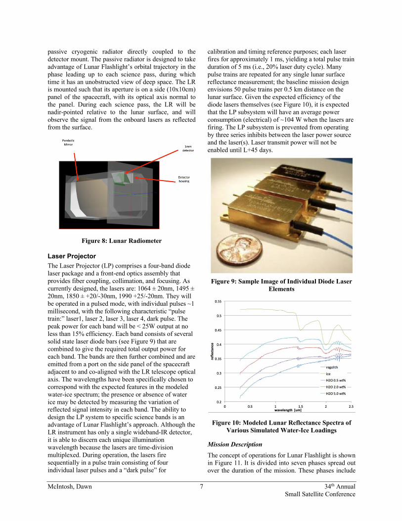
Lunar Radiometer The LR is Lunar Flashlight’s primary science instrument, and consists of an infrared-sensitive detector coupled to a single mirror off-axis parabolic (OAP) telescope with a field of view (FoV) of ~1.5° to 3° and an effective aperture of ~50cm2 (see Figure 8), giving a lunar surface spot size of approximately 1 km diameter. This simple optical system design is typical for those intended for operation in the near-infrared spectrum, approximately 1-2.5 microns wavelength. At the focal plane of this optical system is a single-pixel photodiode detector of indium-gallium-arsenide (InGa:As) chemistry having a cutoff wavelength of 2.2 μm. The single detector design is straightforward to fabricate and align. Such detectors are inexpensive and readily available from several vendors in various package diameters and cutoff wavelengths. This detector is optimized for operation at temperatures below -65°C (208 K); cooling will be provided by a
McIntosh, Dawn 7 34th Annual Small Satellite Conference
passive cryogenic radiator directly coupled to the detector mount. The passive radiator is designed to take advantage of Lunar Flashlight’s orbital trajectory in the phase leading up to each science pass, during which time it has an unobstructed view of deep space. The LR is mounted such that its aperture is on a side (10x10cm) panel of the spacecraft, with its optical axis normal to the panel. During each science pass, the LR will be nadir-pointed relative to the lunar surface, and will observe the signal from the onboard lasers as reflected from the surface.
Figure 8: Lunar Radiometer
Laser Projector The Laser Projector (LP) comprises a four-band diode laser package and a front-end optics assembly that provides fiber coupling, collimation, and focusing. As currently designed, the lasers are: 1064 ± 20nm, 1495 ± 20nm, 1850 ± +20/-30nm, 1990 +25/-20nm. They will be operated in a pulsed mode, with individual pulses ~1 millisecond, with the following characteristic “pulse train:” laser1, laser 2, laser 3, laser 4, dark pulse. The peak power for each band will be < 25W output at no less than 15% efficiency. Each band consists of several solid state laser diode bars (see Figure 9) that are combined to give the required total output power for each band. The bands are then further combined and are emitted from a port on the side panel of the spacecraft adjacent to and co-aligned with the LR telescope optical axis. The wavelengths have been specifically chosen to correspond with the expected features in the modeled water-ice spectrum; the presence or absence of water ice may be detected by measuring the variation of reflected signal intensity in each band. The ability to design the LP system to specific science bands is an advantage of Lunar Flashlight’s approach. Although the LR instrument has only a single wideband-IR detector, it is able to discern each unique illumination wavelength because the lasers are time-division multiplexed. During operation, the lasers fire sequentially in a pulse train consisting of four individual laser pulses and a “dark pulse” for
calibration and timing reference purposes; each laser fires for approximately 1 ms, yielding a total pulse train duration of 5 ms (i.e., 20% laser duty cycle). Many pulse trains are repeated for any single lunar surface reflectance measurement; the baseline mission design envisions 50 pulse trains per 0.5 km distance on the lunar surface. Given the expected efficiency of the diode lasers themselves (see Figure 10), it is expected that the LP subsystem will have an average power consumption (electrical) of ~104 W when the lasers are firing. The LP subsystem is prevented from operating by three series inhibits between the laser power source and the laser(s). Laser transmit power will not be enabled until L+45 days.
Figure 9: Sample Image of Individual Diode Laser
Elements
Figure 10: Modeled Lunar Reflectance Spectra of Various Simulated Water-Ice Loadings
Mission Description The concept of operations for Lunar Flashlight is shown in Figure 11. It is divided into seven phases spread out over the duration of the mission. These phases include
McIntosh, Dawn 8 34th Annual Small Satellite Conference
Deployment, First Lunar Flyby and Loiter, Second & Third Lunar Flybys and Cruise, Lunar Orbit Insertion, Lunar Orbit Trims, Science, and Disposal. Once Lunar Flashlight is deployed and clear of the ICPS, it will begin preprogramed commissioning activities to include detumble, telecommunications activation, propulsion system priming and solar panel deployment. Within the first 12 hours from deployment, Lunar Flashlight will perform a trajectory correction maneuver (TCM#1) to target the first lunar flyby. A clean-up maneuver will be performed approximately 24 hours later to refine the trajectory. After the three lunar flybys, Lunar Flashlight will do a series of large burns of its ‘green propellant’ propulsion system to get into a highly elliptical lunar orbit. It will then do a smaller series of burns to trim that orbit to the final science orbit. Once in the science orbit, twice-daily science observations, tracking, and data downlink will begin. This will continue until there is not enough propellant to maintain the science orbit, at which point the spacecraft will be decommissioned by impacting into the moon.
Figure 11: Lunar Flashlight Concept of Operations NEA SCOUT
Introduction The purpose of the NEA Scout project is to use a novel solar sail navigation system to demonstrate a low-cost capability to perform a precursor robotic mission to a representative Human exploration Near-Earth Asteroid (NEA) target and perform in situ observations to address key SKGs. The Marshall Space Flight Center (MSFC) has been designated as the responsible NASA Center for the NEA Scout Project. MSFC partnered with the Jet Propulsion Laboratory (JPL) in the implementation of the project.
The NEA Scout Project is being approached as a Class III, Risk Classification D project and is governed by MPR 7120.1 (MSFC implementation of NPR 7120.5), with implementation tailored to fit the classification, risk posture and expectations/constraints of a CubeSat project.
Science Goals NEA Scout will navigate to a representative NEA target and perform in situ observations to retire key strategic knowledge gaps (SKGs) for human exploration and scientific understanding of the Near-Earth Orbit population. Given the limited in situ knowledge of asteroids and the limited ability of ground-based assets to address the key SKGs, robotic precursor missions to NEAs which serve as representative targets for future human exploration are critical.
NEA Scout will fly by and characterize the physical properties of a resolved NEA target to determine shape/volume, rotational properties, debris/dust field in local environment, and regolith characteristics. The mission will perform a slow flyby of a NEA that will be chosen based on the launch date for Artemis 1. The measurement goals of the mission are as follows:
• Image at least 80% of the surface at a resolution of 50 cm or less per pixel in the visible spectrum.
• Image at least 30% of the surface at a resolution of 10 cm or less per pixel in the visible spectrum.
Payload Details NEA Scout carries two payloads, the science payload and the propulsion payload.
NEA Scout Science Payload NEA Scout uses a camera developed at the Jet Propulsion Laboratory called the NEA Scout Science Camera with a Medium Field of View (MFOV) optical system. The NEA Scout Science Camera is used for asteroid detection, optical navigation, and proximity science imaging. It builds on the context imaging camera developed by the OCO-3 that is currently under implementation. That camera uses the same detector as the 12 engineering cameras selected for the Mars 2020 mission. The NEA Scout Science Camera leverages JPL’s legacy in camera development, with products such as the Panoramic Camera (PanCam, Mars Exploration Rovers), the navigation cameras on Mars Science Laboratory (MSL) and context cameras on the InSight lander.
McIntosh, Dawn 9 34th Annual Small Satellite Conference
The NEA Scout Science Camera utilizes the Complementary Metal–Oxide–Semiconductor Imaging Sensor (CMOSIS) Machine Vision (CMV20000) 20MPx panchromatic sensor with an output of 12-bit pixels. The camera nominally contains 4 Gb Synchronous Dynamic Random Access Memory (SDRAM), which is used to buffer images from the detector to be read out at a later time.
The NEA Scout Science Camera is 12.4 mm long by 6.2 mm by 6.2 mm with a wavelength range of 400 to 900 nm, an effective focal length of 50.2 mm, a focal ratio of f/2.8, and a 27o field of view. The camera uses the catalog, compact, Xenoplan C-mount lens procured from Schneider, which is designed for the rigors of space flight based on two decades of flight experience. The aperture stop is a fixed waterhouse stop and the focus is set and staked by Schneider, leaving no moving parts in a ruggedized package to withstand the hazards of launch and long-term operation in orbit.
The camera is used both for navigation (during the initial detection and approach to the target) and the science imagery (during the close approach). The optical navigation images will be generated via the same pipeline used for science imaging. The camera meets several key science requirements: sensitive detector capable of detecting the faint NEA Scout baseline target, 2019 GF1, from a distance up to 50,000 km; an instantaneous field of view of 0.09 mrad corresponding to a surface sampling distance of ~10 cm per pixel at ~1.1 km distance at closest approach. The camera is a CMOS monochromatic imager that is based on the context camera developed for the Orbital Carbon Observatory-3, updated to the deep space environmental conditions specific to NEA Scout. The detector is a 20 Megapixel (MPx) array but the image is formed from a fraction of the array. The illuminated region takes the form of a circumscribed square corresponding to 14.7 MPx (3840 pixel diameter).
The camera interfaces with the rest of the spacecraft through a SpaceWire ECSS-E-ST-50-11 Remote Memory Access Protocol (RMAP) communication protocol, 1 wire pair for the 5 Vdc power and return, 2 wire pairs for the temperature sensors and 2 wire pairs for an optics and detector decontamination heater. Electrical power to the camera is about 5 W.
NEA Scout Propulsion Payload The solar sail (see Figure 12 and Figure 13) is a single solar sail that has a total effective sail area of ~86 m2. The sail membrane is made from 2.5 micron thick CP1 material with a unilateral aluminum coating and is Z-folded and then spooled around a single post for stowage. The deployment of the sail is achieved with
four booms which are stainless steel Triangular Rollable And Collapsible (TRAC) booms that are approximately 7.3m in length. These TRAC booms are coiled onto a mechanical deployer and the sail connects to the booms at the tip of each boom. There are two separate deployers and each deployer releases two TRAC booms. The deployment of the TRAC booms and sail is regulated with a motor to temper the strain energy of the booms. The motor is controlled and driven by the Motor Controller Board (MCB), which will receive its power and command from the Flight System.
Figure 12: Solar Sail Flight Unit, spooled
Figure 13: Solar Sail Subsystem Flight Unit, Deployed
A pinpuller mechanism is used to lock the sail spool into its stowed position. When NEA Scout is ready to deploy the sail, the MCB will command the pinpuller to actuate, freeing the spool to rotate. Once the mechanism is released, the TRAC booms are driven into place by the motor over a period of 10-30 minutes.
McIntosh, Dawn 10 34th Annual Small Satellite Conference
Mission Description The NEA Scout mission is a CubeSat with solar sail propulsion. It is designed to navigate to a small (<100m) NEA and perform a brief flyby, during which it will image the target with its visible imager. These images will be processed onboard, and then downlinked over the Deep-Space Network (DSN) for analysis on Earth. The mission will address several key strategic knowledge gaps relevant to asteroid rendezvous, in-situ resource utilization, and safety and operations planning for human in-situ exploration (see Figure 14 for a representation of the mission). Specific investigation objectives include:
• Determination of the target spin rate and pole • Characterization of albedo and surface
morphology • Evaluation of the near-space environment for
dust, satellites, and other potential hazards
Figure 14: NEA Scout NEA Scout will be launched with the Artemis 1. It will reach its target and downlink data from the flyby within 2.5 years. The nominal target is asteroid 2019 GF1. NEA Scout represents several “firsts” including the first small spacecraft flyby of a primitive body, the first encounter of any kind with an asteroid of this size class, and the first time a solar sail has been used for deep space navigation by a CubeSat. Motivated by the restricted bandwidth of its radio and patch antenna configuration, it will also pioneer several novel onboard data analysis strategies including onboard coalignment of star field images to facilitate target detection.
NEA Scout’s mission will involve at least eight distinct phases:
1. Activation – NEA Scout will be deployed to a trans-lunar orbit by the SLS vehicle, and released from a containment structure onboard the secondary stage. It will detumble using
onboard cold gas thrusters and navigate into a lunar gravity-assist trajectory.
2. Cis-Lunar Cruise – NEA Scout will deploy its ~86 m2 solar sail after the first lunar flyby. Subsequent Earth and lunar flybys will enable targeting of cis-lunar escape, enabling asteroid rendezvous.
3. Interplanetary Cruise – NEA Scout will cruise toward the rendezvous target during a mission lasting over two years, adjusting its trajectory by angling the solar sail relative to the sun. Periodic Operational Readiness Tests (ORT) and calibration activities will characterize camera radiometric and geometric performance.
4. Detection – As NEA Scout draws to within 50,000 km range of the target, it will acquire multiple frames covering the projected location of the target based on available ephemeris. Onboard co-registration will merge these exposures and increase the Signal-to-Noise ratio (SNR), without increasing requirements on the stability of the Attitude Control System (ACS). The portion of the co-added frame corresponding to the target uncertainty ellipse will be downlinked to the ground. Multiple such frames can be subtracted on Earth to find moving point source targets.
5. Approach – After detection, the spacecraft approaches the target via a combination of optical navigation and radio tracking. During that period the spacecraft will continue imaging the target at a cadence of once or twice per day to refine its ephemeris.
6. Reconnaissance – The science Reconnaissance phase starts when the target is resolved in NSSI. This phase will last up to 120 min.; the exact duration is a function of the spacecraft velocity and target size. This phase consists in global and regional mapping. The spacecraft will acquire images to characterize the target global shape, rotation period, local environment (dust, debris), and regional morphology.
7. Close Proximity Science – This phase occurs in the final command cycle when NEA Scout is closest to its target. This phase consists of local, high-resolution imaging of the surface.
8. Science Data Downlink – NEA Scout will downlink the data acquired during the Reconnaissance through Close Proximity phases over a span of up to six months due to the very low downlink rate, as low as 1 kbps. An additional six-month period is required for
McIntosh, Dawn 11 34th Annual Small Satellite Conference
processing and delivery of NEA Scout data products to NASA’s Planetary Data System.
SUMMARY From radiation measurements using biological organisms to lunar exploration using lasers to navigating to a Near-Earth asteroid by solar sail, BioSentinel, Lunar Flashlight, and NEA Scout are examples of the breadth of science and exploration goals of the thirteen secondary payloads on the SLS Artemis-1 launch. These three NASA missions are indicative of the types of deep space science and exploration missions that now fit into a 6U CubeSat form factor.


![COTS Assemblies for Class-D Missions : Examples of ......SmallSat Reliability – DJ Sheldon (2017) Heritage and CubeSat Reliability Plotted on Same Curve [2] ... Can cause de-wetting](https://static.documents.pub/doc/80x56/60c5d7f401589f5b295dc743/cots-assemblies-for-class-d-missions-examples-of-smallsat-reliability.jpg)


