60
Instruction Manual First Edition MCON-C/CG SSCNET /H Applicable Controller IAI America, Inc.
Instruction Manual First Edition
MCON-C/CG
SSCNET /H Applicable Controller
IAI America, Inc.

Please Read Before Use Thank you for purchasing our product. This Instruction Manual describes all necessary information items to operate this product safely such as the operation procedure, structure and maintenance procedure. To ensure the safe operation of this product, please read and fully understand this manual. The enclosed DVD in this product package includes the Instruction Manual for this product. For the operation of this product, print out the necessary sections in the Instruction Manual or display them using the personal computer. After reading through this manual, keep this Instruction Manual at hand so that the operator of this product can read it whenever necessary.
[Important] • This Instruction Manual is original. • The product cannot be operated in any way unless expressly specified in this Instruction
Manual. IAI shall assume no responsibility for the outcome of any operation not specified herein.
• Information contained in this Instruction Manual is subject to change without notice for the purpose of product improvement.
• If you have any question or comment regarding the content of this manual, please contact the IAI sales office near you.
• Using or copying all or part of this Instruction Manual without permission is prohibited. • SSCNET ΙΙΙ/H is a registered trademark of Mitsubishi Electric Corporation. • The company names, names of products and trademarks of each company shown in the
sentences are registered trademarks.

MCON-C/CG
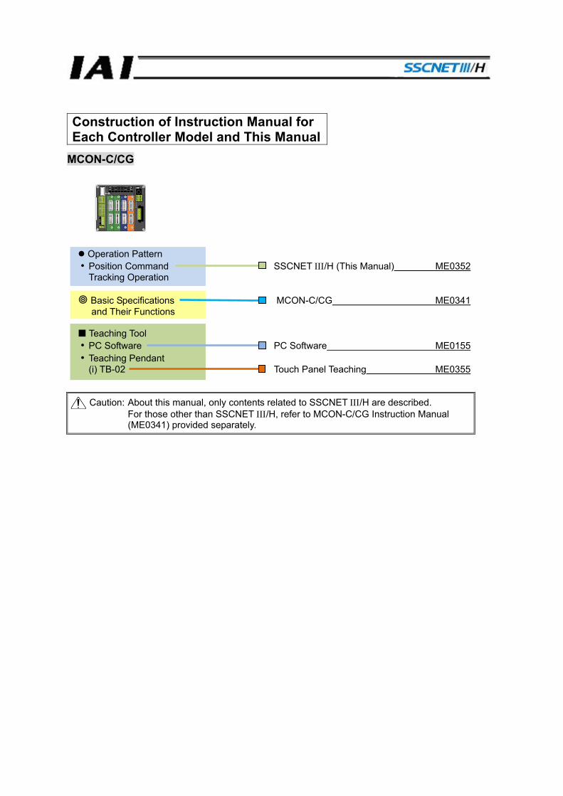
Construction of Instruction Manual for Each Controller Model and This Manual
Caution: About this manual, only contents related to SSCNET ΙΙΙ/H are described. For those other than SSCNET ΙΙΙ/H, refer to MCON-C/CG Instruction Manual (ME0341) provided separately.
Operation Pattern • Position Command SSCNET ΙΙΙ/H (This Manual) ME0352 Tracking Operation
Basic Specifications MCON-C/CG ME0341 and Their Functions
Teaching Tool
• PC Software PC Software ME0155 • Teaching Pendant (i) TB-02 Touch Panel Teaching ME0355

Table of Overall Contents
1. Overview 9
2. Controller Setting 10
3. SSCNET ΙΙΙ/H Basic Communication Flow 15
4. Cautions in Actuator Operation 25
5. IAI Controller Parameters 26
6. Troubleshooting 30
7. Appendix 44
Table of Contents Safety Guide........................................................................................................................ 1 Precautions in Operation..................................................................................................... 8 1. Overview ...................................................................................................................... 9
1.1 Interface Specifications..................................................................................................... 9 2. Controller Setting........................................................................................................ 10
2.1 Model .............................................................................................................................. 10 2.2 Interface.......................................................................................................................... 10 2.3 Setting of Status LED Display......................................................................................... 11 2.4 Wiring Example .............................................................................................................. 11 2.5 MCON Controller Setting................................................................................................ 12
2.5.1 Startup of Gateway Parameter Setting Tool (Preparation for Setting) ....................... 12 2.5.2 Setting of the Address................................................................................................ 12 2.5.3 Setting of the No. of Axes to Be Mounted and Reserved Axes ................................. 13 2.5.4 Applying Parameters (Transfer to Controller) ............................................................ 13 2.5.5 Setting of Pulse Count Direction................................................................................ 14 2.5.6 Setting of Electronic Gear Ratio................................................................................. 14
3. SSCNET ΙΙΙ/H Basic Communication Flow ................................................................ 15 3.1 How to Make Connection (Flow) .................................................................................... 17 3.2 Optional Data Monitor..................................................................................................... 18
3.2.1 Registration Monitor................................................................................................... 18 3.2.2 Transient Commands................................................................................................. 22
4. Cautions in Actuator Operation .................................................................................. 25 4.1 Home return.................................................................................................................... 25 4.2 Soft Limit......................................................................................................................... 25
5. IAI Controller Parameters........................................................................................... 26 5.1 Parameter List ................................................................................................................ 27
6. Troubleshooting.......................................................................................................... 30 6.1 Action to Be Taken upon Occurrence of Problem .......................................................... 30 6.2 Alarm Level..................................................................................................................... 31 6.3 Operation Alarm.............................................................................................................. 31 6.4 Driver Alarm.................................................................................................................... 32 6.5 Simple Alarm Code......................................................................................................... 33 6.6 Alarm List........................................................................................................................ 34
7. Appendix .................................................................................................................... 44 7.1 Necessary Devices and Software................................................................................... 44 7.2 How to Establish Connection.......................................................................................... 44
8. Change History........................................................................................................... 49

1
Safety Guide “Safety Guide” has been written to use the machine safely and so prevent personal injury or property damage beforehand. Make sure to read it before the operation of this product.
Safety Precautions for Our Products The common safety precautions for the use of any of our robots in each operation.
No. Operation Description Description
1 Model Selection
● This product has not been planned and designed for the application where high level of safety is required, so the guarantee of the protection of human life is impossible. Accordingly, do not use it in any of the following applications. 1) Medical equipment used to maintain, control or otherwise affect
human life or physical health. 2) Mechanisms and machinery designed for the purpose of moving or
transporting people (For vehicle, railway facility or air navigation facility)
3) Important safety parts of machinery (Safety device, etc.) ● Do not use the product outside the specifications. Failure to do so may
considerably shorten the life of the product. ● Do not use it in any of the following environments.
1) Location where there is any inflammable gas, inflammable object or explosive
2) Place with potential exposure to radiation 3) Location with the ambient temperature or relative humidity exceeding
the specification range 4) Location where radiant heat is added from direct sunlight or other
large heat source 5) Location where condensation occurs due to abrupt temperature
changes 6) Location where there is any corrosive gas (sulfuric acid or
hydrochloric acid) 7) Location exposed to significant amount of dust, salt or iron powder 8) Location subject to direct vibration or impact
● For an actuator used in vertical orientation, select a model which is equipped with a brake. If selecting a model with no brake, the moving part may drop when the power is turned OFF and may cause an accident such as an injury or damage on the work piece.
2
No. Operation Description Description
2 Transportation ● When carrying a heavy object, do the work with two or more persons or utilize equipment such as crane.
● When the work is carried out with 2 or more persons, make it clear who is to be the leader and who to be the follower(s) and communicate well with each other to ensure the safety of the workers.
● When in transportation, consider well about the positions to hold, weight and weight balance and pay special attention to the carried object so it would not get hit or dropped.
● Transport it using an appropriate transportation measure. The actuators available for transportation with a crane have eyebolts attached or there are tapped holes to attach bolts. Follow the instructions in the instruction manual for each model.
● Do not step or sit on the package. ● Do not put any heavy thing that can deform the package, on it. ● When using a crane capable of 1t or more of weight, have an operator
who has qualifications for crane operation and sling work. ● When using a crane or equivalent equipments, make sure not to hang a
load that weighs more than the equipment’s capability limit. ● Use a hook that is suitable for the load. Consider the safety factor of the
hook in such factors as shear strength. ● Do not get on the load that is hung on a crane. ● Do not leave a load hung up with a crane. ● Do not stand under the load that is hung up with a crane.
3 Storage and Preservation
● The storage and preservation environment conforms to the installation environment. However, especially give consideration to the prevention of condensation.
● Store the products with a consideration not to fall them over or drop due to an act of God such as earthquake.
4 Installation and Start
(1) Installation of Robot Main Body and Controller, etc. ● Make sure to securely hold and fix the product (including the work part).
A fall, drop or abnormal motion of the product may cause a damage or injury. Also, be equipped for a fall-over or drop due to an act of God such as earthquake.
● Do not get on or put anything on the product. Failure to do so may cause an accidental fall, injury or damage to the product due to a drop of anything, malfunction of the product, performance degradation, or shortening of its life.
● When using the product in any of the places specified below, provide a sufficient shield. 1) Location where electric noise is generated 2) Location where high electrical or magnetic field is present 3) Location with the mains or power lines passing nearby 4) Location where the product may come in contact with water, oil or
chemical droplets
3
No. Operation Description Description
(2) Cable Wiring ● Use our company’s genuine cables for connecting between the actuator
and controller, and for the teaching tool. ● Do not scratch on the cable. Do not bend it forcibly. Do not pull it. Do not
coil it around. Do not insert it. Do not put any heavy thing on it. Failure to do so may cause a fire, electric shock or malfunction due to leakage or continuity error.
● Perform the wiring for the product, after turning OFF the power to the unit, so that there is no wiring error.
● When the direct current power (+24V) is connected, take the great care of the directions of positive and negative poles. If the connection direction is not correct, it might cause a fire, product breakdown or malfunction.
● Connect the cable connector securely so that there is no disconnection or looseness. Failure to do so may cause a fire, electric shock or malfunction of the product.
● Never cut and/or reconnect the cables supplied with the product for the purpose of extending or shortening the cable length. Failure to do so may cause the product to malfunction or cause fire.
4 Installation and Start
(3) Grounding ● The grounding operation should be performed to prevent an electric
shock or electrostatic charge, enhance the noise-resistance ability and control the unnecessary electromagnetic radiation.
● For the ground terminal on the AC power cable of the controller and the grounding plate in the control panel, make sure to use a twisted pair cable with wire thickness 0.5mm2 (AWG20 or equivalent) or more for grounding work. For security grounding, it is necessary to select an appropriate wire thickness suitable for the load. Perform wiring that satisfies the specifications (electrical equipment technical standards).
● Perform Class D Grounding (former Class 3 Grounding with ground resistance 100Ω or below).
4
No. Operation Description Description
4 Installation and Start
(4) Safety Measures ● When the work is carried out with 2 or more persons, make it clear who
is to be the leader and who to be the follower(s) and communicate well with each other to ensure the safety of the workers.
● When the product is under operation or in the ready mode, take the safety measures (such as the installation of safety and protection fence) so that nobody can enter the area within the robot’s movable range. When the robot under operation is touched, it may result in death or serious injury.
● Make sure to install the emergency stop circuit so that the unit can be stopped immediately in an emergency during the unit operation.
● Take the safety measure not to start up the unit only with the power turning ON. Failure to do so may start up the machine suddenly and cause an injury or damage to the product.
● Take the safety measure not to start up the machine only with the emergency stop cancellation or recovery after the power failure. Failure to do so may result in an electric shock or injury due to unexpected power input.
● When the installation or adjustment operation is to be performed, give clear warnings such as “Under Operation; Do not turn ON the power!” etc. Sudden power input may cause an electric shock or injury.
● Take the measure so that the work part is not dropped in power failure or emergency stop.
● Wear protection gloves, goggle or safety shoes, as necessary, to secure safety.
● Do not insert a finger or object in the openings in the product. Failure to do so may cause an injury, electric shock, damage to the product or fire.
● When releasing the brake on a vertically oriented actuator, exercise precaution not to pinch your hand or damage the work parts with the actuator dropped by gravity.
5 Teaching ● When the work is carried out with 2 or more persons, make it clear who is to be the leader and who to be the follower(s) and communicate well with each other to ensure the safety of the workers.
● Perform the teaching operation from outside the safety protection fence, if possible. In the case that the operation is to be performed unavoidably inside the safety protection fence, prepare the “Stipulations for the Operation” and make sure that all the workers acknowledge and understand them well.
● When the operation is to be performed inside the safety protection fence, the worker should have an emergency stop switch at hand with him so that the unit can be stopped any time in an emergency.
● When the operation is to be performed inside the safety protection fence, in addition to the workers, arrange a watchman so that the machine can be stopped any time in an emergency. Also, keep watch on the operation so that any third person can not operate the switches carelessly.
● Place a sign “Under Operation” at the position easy to see. ● When releasing the brake on a vertically oriented actuator, exercise
precaution not to pinch your hand or damage the work parts with the actuator dropped by gravity.
* Safety protection Fence : In the case that there is no safety protection fence, the movable range should be indicated.

5
No. Operation Description Description
6 Trial Operation
● When the work is carried out with 2 or more persons, make it clear who is to be the leader and who to be the follower(s) and communicate well with each other to ensure the safety of the workers.
● After the teaching or programming operation, perform the check operation one step by one step and then shift to the automatic operation.
● When the check operation is to be performed inside the safety protection fence, perform the check operation using the previously specified work procedure like the teaching operation.
● Make sure to perform the programmed operation check at the safety speed. Failure to do so may result in an accident due to unexpected motion caused by a program error, etc.
● Do not touch the terminal block or any of the various setting switches in the power ON mode. Failure to do so may result in an electric shock or malfunction.
7 Automatic Operation
● Check before starting the automatic operation or rebooting after operation stop that there is nobody in the safety protection fence.
● Before starting automatic operation, make sure that all peripheral equipment is in an automatic-operation-ready state and there is no alarm indication.
● Make sure to operate automatic operation start from outside of the safety protection fence.
● In the case that there is any abnormal heating, smoke, offensive smell, or abnormal noise in the product, immediately stop the machine and turn OFF the power switch. Failure to do so may result in a fire or damage to the product.
● When a power failure occurs, turn OFF the power switch. Failure to do so may cause an injury or damage to the product, due to a sudden motion of the product in the recovery operation from the power failure.

6
No. Operation Description Description
8 Maintenance and Inspection
● When the work is carried out with 2 or more persons, make it clear who is to be the leader and who to be the follower(s) and communicate well with each other to ensure the safety of the workers.
● Perform the work out of the safety protection fence, if possible. In the case that the operation is to be performed unavoidably inside the safety protection fence, prepare the “Stipulations for the Operation” and make sure that all the workers acknowledge and understand them well.
● When the work is to be performed inside the safety protection fence, basically turn OFF the power switch.
● When the operation is to be performed inside the safety protection fence, the worker should have an emergency stop switch at hand with him so that the unit can be stopped any time in an emergency.
● When the operation is to be performed inside the safety protection fence, in addition to the workers, arrange a watchman so that the machine can be stopped any time in an emergency. Also, keep watch on the operation so that any third person can not operate the switches carelessly.
● Place a sign “Under Operation” at the position easy to see. ● For the grease for the guide or ball screw, use appropriate grease
according to the Instruction Manual for each model. ● Do not perform the dielectric strength test. Failure to do so may result in
a damage to the product. ● When releasing the brake on a vertically oriented actuator, exercise
precaution not to pinch your hand or damage the work parts with the actuator dropped by gravity.
● The slider or rod may get misaligned OFF the stop position if the servo is turned OFF. Be careful not to get injured or damaged due to an unnecessary operation.
● Pay attention not to lose the cover or untightened screws, and make sure to put the product back to the original condition after maintenance and inspection works. Use in incomplete condition may cause damage to the product or an injury.
* Safety protection Fence : In the case that there is no safety protection fence, the movable range should be indicated.
9 Modification and Dismantle
● Do not modify, disassemble, assemble or use of maintenance parts not specified based at your own discretion.
10 Disposal ● When the product becomes no longer usable or necessary, dispose of it properly as an industrial waste.
● When removing the actuator for disposal, pay attention to drop of components when detaching screws.
● Do not put the product in a fire when disposing of it. The product may burst or generate toxic gases.
11 Other ● Do not come close to the product or the harnesses if you are a person who requires a support of medical devices such as a pacemaker. Doing so may affect the performance of your medical device.
● See Overseas Specifications Compliance Manual to check whether complies if necessary.
● For the handling of actuators and controllers, follow the dedicated instruction manual of each unit to ensure the safety.

7
Alert Indication The safety precautions are divided into “Danger”, “Warning”, “Caution” and “Notice” according to the warning level, as follows, and described in the Instruction Manual for each model.
Level Degree of Danger and Damage Symbol
Danger This indicates an imminently hazardous situation which, if the product is not handled correctly, will result in death or serious injury.
Danger
Warning This indicates a potentially hazardous situation which, if the product is not handled correctly, could result in death or serious injury.
Warning
Caution This indicates a potentially hazardous situation which, if the product is not handled correctly, may result in minor injury or property damage.
Caution
Notice This indicates lower possibility for the injury, but should be kept to use this product properly. Notice
8
Precautions in Operation 1. Backup the data to secure for breakdown.
A non-volatile memory is used as the backup memory for MCON. All the registered parameters are written into this memory and backed-up at the same time. Therefore, you will not usually lose the data even if the power is shut down. However, make sure to save the latest data so a quick recovery action can be taken in case when the MCON is broken and needs to be replaced with another one. How to Save Data (1) Save to a storage medium such as a hard disk using PC software. (2) Hard-copy the information of position tables and parameters on paper
2. Initializing Time
MCON requires 4sec. of initializing time at the startup. Communication cannot be performed during initializing time. For SSCNET III/H Controller, make sure to secure 4sec. or more of standby time for connection till it gets available for communication after turning the power on. During the initializing time, connection is not allowed even for the slave at the bottom flow of the network connected to MCON. Refer to the instruction manual for SSCNET ΙΙΙ/H Controller for detail of how to check the slave connection status.
3. In Case of Control Power Voltage Drop Communication will be stopped if MCON detects a drop in the control power voltage. Connect to the network again after recovery of the control power.
4. In Case Operation Mode Setting Switch Set to MANU
Axis operation commands from the SSCNET ΙΙΙ/H network are not available if the operation mode setting switch on the front of an MCON is on MANU. Set it to AUTO. Switching to MANU Mode during in operation in AUTO Mode will cause the driver alarm (E0h). In such a case, the status or monitor information from MCON will remain to the latest update.
5. In Case of Communication Error with SSCNETⅢ/H If a communication error occurred when the operation mode setting switch is set to AUTO, MCON turns the servo OFF compulsorily to actuate the brake. The process to turn the servo OFF compulsorily to actuate the brake will not be taken when set to MANU.
6. Regarding Encoder Type Even though MCON are capable for operation with incremental type and absolute type (including battery-less) being connected, make sure to set to “Incremental Type” on the SSCNET ΙΙΙ/H Controller side regardless of the connected encoder type.
7. Regarding Rotary Type Index Mode The rotary type index mode is not available.
1. Overview
9
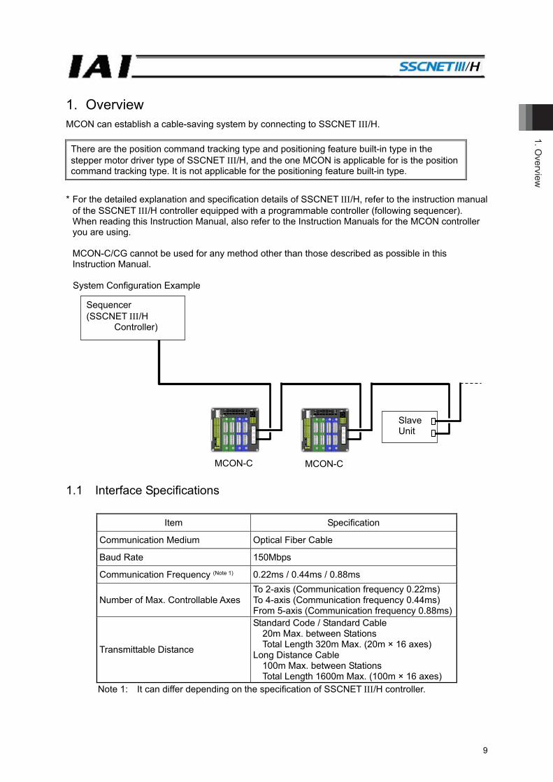
1. Overview MCON can establish a cable-saving system by connecting to SSCNET /H.
* For the detailed explanation and specification details of SSCNET /H, refer to the instruction manual
of the SSCNET /H controller equipped with a programmable controller (following sequencer). When reading this Instruction Manual, also refer to the Instruction Manuals for the MCON controller you are using. MCON-C/CG cannot be used for any method other than those described as possible in this Instruction Manual.
System Configuration Example
1.1 Interface Specifications
Item Specification
Communication Medium Optical Fiber Cable
Baud Rate 150Mbps
Communication Frequency (Note 1) 0.22ms / 0.44ms / 0.88ms
Number of Max. Controllable Axes To 2-axis (Communication frequency 0.22ms) To 4-axis (Communication frequency 0.44ms) From 5-axis (Communication frequency 0.88ms)
Transmittable Distance
Standard Code / Standard Cable 20m Max. between Stations Total Length 320m Max. (20m × 16 axes)
Long Distance Cable 100m Max. between Stations Total Length 1600m Max. (100m × 16 axes)
Note 1: It can differ depending on the specification of SSCNET /H controller.
There are the position command tracking type and positioning feature built-in type in the stepper motor driver type of SSCNET /H, and the one MCON is applicable for is the position command tracking type. It is not applicable for the positioning feature built-in type.
Sequencer (SSCNET /H
Controller)
MCON-CMCON-C
Slave Unit

2. C
ontro
ller S
ettin
g
10
2. Controller Setting 2.1 Model The model code of IAI controllers in SSCNET /H type is described as shown below. MCON-C(CG)--SSN- 2.2 Interface The names of each section related to SSNET /H are described as follows.
P2 (Port 2) Connect to bottom line of network
P1 (Port 1) Connect to top line of network (such as SSCNET /H controller)
C.ERR LED
ERR LED
RUN LED

2. Controller Setting
11
2.3 Setting of Status LED Display With the three LED lamps allocated on the front of the controller, condition of communication board and network status can be notified. ○: Illuminating, ☆: Flashing, ×: Off
LED Color Illumination Status Description
RUN Green ○
In network initialization, or in normal communication status with connection to Sequencer * For MCON, this lamp turns on when any of the axes is
connected. - × Sequencer not connected, or power turned off
ERR Orange ○ Communication alarm is generated * For MCON, this lamp turns on when any of the axes is
connected. Orange ☆ Error in network initialization
- × In normal condition (no alarm generated), Communication alarm cancelled
C.ERR (C Error) Orange ○ Sequencer not connected, or network in initialization
2.4 Wiring Example * To the two connectors for SSCNET /H connection, connect the cable of the network top line to P1
and that of the network bottom line to P2.
Sequencer (SSCNET /H Controller)
Optical Fiber Cable Dedicated for SSCNET /H
MCON-C-SSN Slave Unit
Optical Fiber Cable Dedicated for SSCNET /H
MCON-C-SSN

2. C
ontro
ller S
ettin
g
12
2.5 MCON Controller Setting Settings are to be established on Gateway Parameter Setting Tool* (ver. 2.4.0.0 or later) and in a teaching tool in such as RC PC software. * For Gateway Parameter Setting Tool, install the file stored in the CD-ROM for RC PC software, or
download from our homepage. When setting the parameters, make sure to set the operation mode setting switch on the front panel of MCON to MANU side.
2.5.1 Startup of Gateway Parameter Setting Tool (Preparation for Setting) Once starting up Gateway Parameter Setting Tool, model selection window opens. Select “MSEP (Motion)”. Select the unit number* to connect, and the initial window appears. * Unit No. 0 = MCON-axis No. 0 to 7, Unit No. 1 = MCON-axis No. 8 to 15
Press the load button to start reading parameters.
Model Select Window
Initial Window Example of Window after reading Parameters
2.5.2 Setting of the Address The address is to be set in “Address” in Gateway Parameter Setting Tool. The address occupies area for the number of driver boards × 2. Set the top value of the occupied address.
Settable Range: 1 to 64 (It is set to “1” when the machine is delivered from the factory.) (Note) Pay attention not to have duplication of address.
Refer to the instruction manuals of the master unit and mounted sequencer for details.
e.g: When assigning for (1) MCON (6 axes), (2) MCON (4 axes) from Address 6 in a row As MCON in (1) occupies Addresses 6 to 11, the setting of the address should be “6”. As MCON in (2) comes after (1), it occupies Addresses 12 to 15. The address setting should be “12”.
2. Controller Setting
13
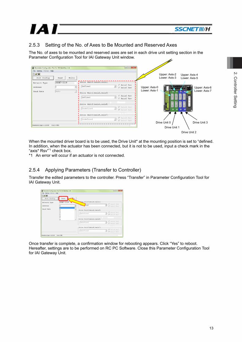
2.5.3 Setting of the No. of Axes to Be Mounted and Reserved Axes The No. of axes to be mounted and reserved axes are set in each drive unit setting section in the Parameter Configuration Tool for IAI Gateway Unit window.
When the mounted driver board is to be used, the Drive Unit* at the mounting position is set to “defined. In addition, when the actuator has been connected, but it is not to be used, input a check mark in the “axis* Rsv”*1 check box. *1 An error will occur if an actuator is not connected. 2.5.4 Applying Parameters (Transfer to Controller) Transfer the edited parameters to the controller. Press “Transfer” in Parameter Configuration Tool for IAI Gateway Unit.
Once transfer is complete, a confirmation window for rebooting appears. Click “Yes” to reboot. Hereafter, settings are to be performed on RC PC Software. Close this Parameter Configuration Tool for IAI Gateway Unit.
Drive Unit 0 Drive Unit 3 Drive Unit 1
Drive Unit 2
Upper: Axis-0Lower: Axis-1
Upper: Axis-2 Lower: Axis-3
Upper: Axis-4 Lower: Axis-5
Upper: Axis-6 Lower: Axis-7
2. C
ontro
ller S
ettin
g
14
2.5.5 Setting of Pulse Count Direction The direction for pulse count operation should be set in a parameter. It is recommend to set the same value as that set in Parameter No. 5 “Home-return Direction” to Parameter No. 62 “Pulse Count Direction” in the RC PC software. [Refer to SSCNET /H Related Parameters] The relation between the home-return direction parameter and the pulse count direction parameter is as described below. ■Home-Return Direction = Pulse Count Direction ⇒ It is the recommended setting.
The sign of the motion network position coordinates and that of the position coordinates viewed from the PC tool are consistent with each other.
■Home-Return Direction ≠ Pulse Count Direction ⇒ The position coordinates on the motion network side can be used in negative side.
The sign of the motion network position coordinates and that of the position coordinates viewed from the teaching tool are not consistent with each other. Be aware that, if the operation mode is switched to the manual operation (MANU) and view the current position from the PC tool, the sign should be positive.
* The parameters in the pulse count direction should impact only in the parts communicated with the motion network, and coordinates will be reversed.
2.5.6 Setting of Electronic Gear Ratio The electronic gear ratio is set with parameters. Confirm that the settings of Parameter No. 65 “Electronic Gear Numerator” and No. 66 “Electronic Gear Denominator” comes to 1/1 in the RC PC software. [Refer to SSCNET /H Related Parameters] * After the setting has been completed, restart the system with the power turned OFF and ON again.
3. 3. SSCN
ET III /H Basic C
omm
unication Flow
15
3. SSCNET /H Basic Communication Flow
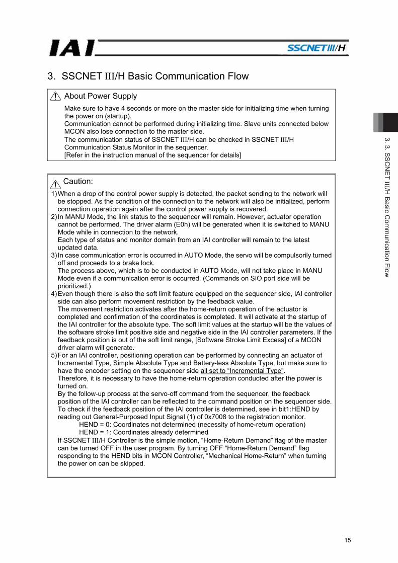
About Power Supply Make sure to have 4 seconds or more on the master side for initializing time when turning the power on (startup). Communication cannot be performed during initializing time. Slave units connected below MCON also lose connection to the master side. The communication status of SSCNET /H can be checked in SSCNET /H Communication Status Monitor in the sequencer. [Refer in the instruction manual of the sequencer for details]
Caution: 1) When a drop of the control power supply is detected, the packet sending to the network will
be stopped. As the condition of the connection to the network will also be initialized, perform connection operation again after the control power supply is recovered.
2) In MANU Mode, the link status to the sequencer will remain. However, actuator operation cannot be performed. The driver alarm (E0h) will be generated when it is switched to MANU Mode while in connection to the network. Each type of status and monitor domain from an IAI controller will remain to the latest updated data.
3) In case communication error is occurred in AUTO Mode, the servo will be compulsorily turned off and proceeds to a brake lock. The process above, which is to be conducted in AUTO Mode, will not take place in MANU Mode even if a communication error is occurred. (Commands on SIO port side will be prioritized.)
4) Even though there is also the soft limit feature equipped on the sequencer side, IAI controller side can also perform movement restriction by the feedback value. The movement restriction activates after the home-return operation of the actuator is completed and confirmation of the coordinates is completed. It will activate at the startup of the IAI controller for the absolute type. The soft limit values at the startup will be the values of the software stroke limit positive side and negative side in the IAI controller parameters. If the feedback position is out of the soft limit range, [Software Stroke Limit Excess] of a MCON driver alarm will generate.
5) For an IAI controller, positioning operation can be performed by connecting an actuator of Incremental Type, Simple Absolute Type and Battery-less Absolute Type, but make sure to have the encoder setting on the sequencer side all set to “Incremental Type”. Therefore, it is necessary to have the home-return operation conducted after the power is turned on. By the follow-up process at the servo-off command from the sequencer, the feedback position of the IAI controller can be reflected to the command position on the sequencer side.To check if the feedback position of the IAI controller is determined, see in bit1:HEND by reading out General-Purposed Input Signal (1) of 0x7008 to the registration monitor.
HEND = 0: Coordinates not determined (necessity of home-return operation) HEND = 1: Coordinates already determined
If SSCNET /H Controller is the simple motion, “Home-Return Demand” flag of the master can be turned OFF in the user program. By turning OFF “Home-Return Demand” flag responding to the HEND bits in MCON Controller, “Mechanical Home-Return” when turning the power on can be skipped.
3. S
SCN
ET III/H
Bas
ic C
omm
unic
atio
n Fl
ow
16
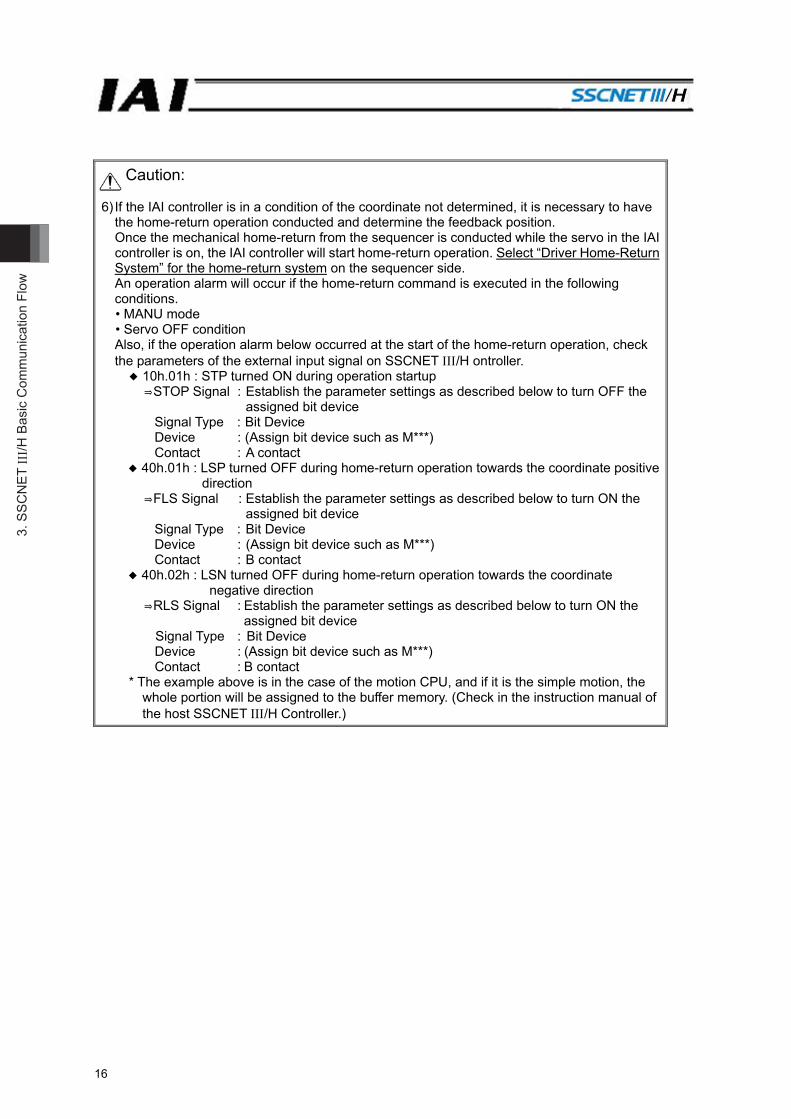
Caution:
6) If the IAI controller is in a condition of the coordinate not determined, it is necessary to have the home-return operation conducted and determine the feedback position. Once the mechanical home-return from the sequencer is conducted while the servo in the IAI controller is on, the IAI controller will start home-return operation. Select “Driver Home-Return System” for the home-return system on the sequencer side. An operation alarm will occur if the home-return command is executed in the following conditions. • MANU mode • Servo OFF condition Also, if the operation alarm below occurred at the start of the home-return operation, check the parameters of the external input signal on SSCNET /H ontroller. ◆ 10h.01h : STP turned ON during operation startup ⇒STOP Signal : Establish the parameter settings as described below to turn OFF the
assigned bit device Signal Type : Bit Device Device : (Assign bit device such as M***) Contact : A contact
◆ 40h.01h : LSP turned OFF during home-return operation towards the coordinate positive direction
⇒FLS Signal : Establish the parameter settings as described below to turn ON the assigned bit device
Signal Type : Bit Device Device : (Assign bit device such as M***) Contact : B contact
◆ 40h.02h : LSN turned OFF during home-return operation towards the coordinate negative direction
⇒RLS Signal : Establish the parameter settings as described below to turn ON the assigned bit device
Signal Type : Bit Device Device : (Assign bit device such as M***) Contact : B contact
* The example above is in the case of the motion CPU, and if it is the simple motion, the whole portion will be assigned to the buffer memory. (Check in the instruction manual of the host SSCNET /H Controller.)
3. 3. SSCN
ET III /H Basic C
omm
unication Flow
17
3.1 How to Make Connection (Flow) [Refer to 7.2, How to Establish Connection.] (1) Please start up the setting software (e.g. GX-Works2). (2) Please register the motion unit model code to be used for the intelligent feature unit. (3) Please create a new project. (4) Please open the system setting window, and establish the setting for the information of the
connected axes (= select “Driver for IAI Electric Actuator (IAI)” from Servo Amplifier Series in Servo Amplifier Information).
(5) Please perform setting of (4) for the number of connected axes. (6) Please establish the parameter setting as followed.
• Unit Setting = “PULSE” • Movement Amount per Load Rotation = “Number of Encoder Pulses of Actuator” (Note 1) • Home-Return System = “Driver Home-Return System” • Input Signal Logic Select = “Negative Logic”
(7) Please set the positioning data for each connected axis.
Please set the positioning address (target position) and command velocity in pulse unit. Also, set the dwell time to 150ms (reference). For also STOP Signal, FLS Signal and RLS Signal of the external signal parameters, establish the settings to what is described in the caution in the previous page.
(8) Please write the setting into the master unit. (9) Please execute Servo-on → Home Return from the monitor window of the motion controller. (10) Indicate the positioning data number that the target position was registered, and press the start
button to move the actuator to the target position. Note 1: Set a value calculated by Number of Encoder Pulse / Gear Ratio to an actuator equipped with
a speed reducer (such as gripper and rotary).
3. S
SCN
ET III/H
Bas
ic C
omm
unic
atio
n Fl
ow
18
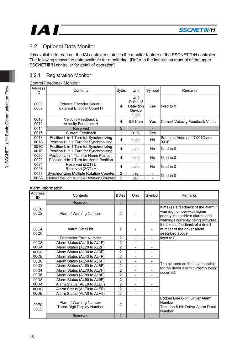
3.2 Optional Data Monitor It is available to read out the IAI controller status in the monitor feature of the SSCNETⅢ/H controller. The following shows the data available for monitoring. [Refer to the instruction manual of the upper SSCNETⅢ/H controller for detail of operation] 3.2.1 Registration Monitor Control Feedback Monitor 1 Address
ID Contents Bytes Unit Symbol Remarks
0000 0002
External Encoder Count L External Encoder Count H 4
Unit Pulse of
Detection Devicepulse
Yes fixed to 0
0010 0012
Velocity Feedback L Velocity Feedback H 4 0.01rpm Yes Current Velocity Feedback Value
0014 0016
Reserved 2 - - Current Feedback 2 0.1% Yes
0018 001A
Position L in 1 Turn for SynchronizingPosition H in 1 Turn for Synchronizing 4 pulse No Same as Address ID 001C and
001E 001C 001E
Position L in 1 Turn for SynchronizingPosition H in 1 Turn for Synchronizing 4 pulse No fixed to 0
0020 0022
Position L in 1 Turn for Home PositionPosition H in 1 Turn for Home Position 4 pulse No fixed to 0
0024 0026
Reserved (ZCT) L Reserved (ZCT) H 4 pulse No fixed to 0
0028 002A
Synchronizing Multiple Rotation Counter 2 rev - fixed to 0 Home Position Multiple Rotation Counter 2 rev -
Alarm Information Address
ID Contents Bytes Unit Symbol Remarks
00C0 00C2
Reserved 2 - -
Alarm / Warning Number 2 - -
It makes a feedback of the alarm / warning number with higher priority in the driver alarms and warnings currently being occurred
00C4 00C6
Alarm Detail bit 2 - - It makes a feedback of a detail number of the driver alarm described above
Parameter Error Number 2 - - fixed to 0 00C8 00CA
Alarm Status (AL10 to AL1F) 2 - -
The bit turns on that is applicable for the driver alarm currently being occurred.
Alarm Status (AL20 to AL2F) 2 - - 00CC 00CE
Alarm Status (AL30 to AL3F) 2 - - Alarm Status (AL40 to AL4F) 2 - -
00D0 00D2
Alarm Status (AL50 to AL5F) 2 - - Alarm Status (AL60 to AL6F) 2 - -
00D4 00D6
Alarm Status (AL70 to AL7F) 2 - - Alarm Status (AL80 to AL8F) 2 - -
00D8 00DA
Alarm Status (AL90 to AL9F) 2 - - Alarm Status (ALE0 to ALEF) 2 - -
00DC 00DE
Alarm Status (ALF0 to ALFF) 2 - - Alarm Status (ALA0 to ALA9) 2 - -
00E0 00E2
Alarm / Warning Number Three-Digit Display Number 2 - -
Bottom Line 8-bit: Driver Alarm Number Top Line 8-bit: Driver Alarm Detail Number
Reserved 2 - -
3. 3. SSCN
ET III /H Basic C
omm
unication Flow
19
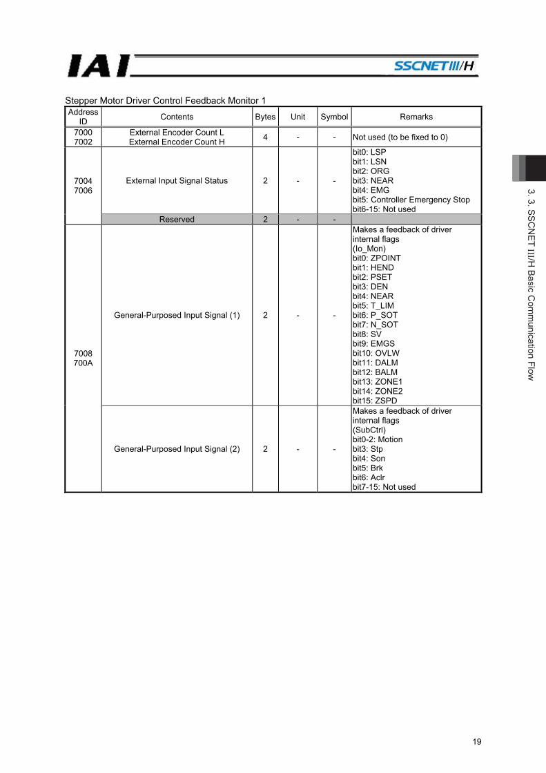
Stepper Motor Driver Control Feedback Monitor 1 Address
ID Contents Bytes Unit Symbol Remarks
7000 7002
External Encoder Count L External Encoder Count H 4 - - Not used (to be fixed to 0)
7004 7006
External Input Signal Status 2 - -
bit0: LSP bit1: LSN bit2: ORG bit3: NEAR bit4: EMG bit5: Controller Emergency Stop bit6-15: Not used
Reserved 2 - -
7008 700A
General-Purposed Input Signal (1) 2 - -
Makes a feedback of driver internal flags (Io_Mon) bit0: ZPOINT bit1: HEND bit2: PSET bit3: DEN bit4: NEAR bit5: T_LIM bit6: P_SOT bit7: N_SOT bit8: SV bit9: EMGS bit10: OVLW bit11: DALM bit12: BALM bit13: ZONE1 bit14: ZONE2 bit15: ZSPD
General-Purposed Input Signal (2) 2 - -
Makes a feedback of driver internal flags (SubCtrl) bit0-2: Motion bit3: Stp bit4: Son bit5: Brk bit6: Aclr bit7-15: Not used

3. S
SCN
ET III/H
Bas
ic C
omm
unic
atio
n Fl
ow
20
Stepper Motor Driver Operation Alarm Information Address
ID Contents Bytes Unit Symbol Remarks
70C0 70C2
Reserved 2 - -
Operation Alarm Number 2 - -
It makes a feedback of the alarm number with higher priority in the driver alarms currently being occurred
70C4 70C6
Operation Alarm Detail bit 2 - - It makes a feedback of a detail number of the driver alarm described above
Reserved 2 - - 70C8 70CA
Operation Alarm Status (AL10 to AL1F) 2 - -
The bit turns on that is applicable for the driver alarm currently being occurred.
Operation Alarm Status (AL20 to AL2F) 2 - - 70CC 70CE
Operation Alarm Status (AL30 to AL3F) 2 - - Operation Alarm Status (AL40 to AL4F) 2 - -
70D0 70D2
Operation Alarm Status (AL50 to AL5F) 2 - - Operation Alarm Status (AL60 to AL6F) 2 - -
70D4 70D6
Operation Alarm Status (AL70 to AL7F) 2 - - Operation Alarm Status (AL80 to AL8F) 2 - -
70D8 70DA
Operation Alarm Status (AL90 to AL9F) 2 - - Operation Alarm Status (ALA0 to ALAF) 2 - -
70DC 70DE
Operation Alarm Status (ALB0 to ALBF) 2 - - Operation Alarm Status (ALC0 to ALCF) 2 - -
70E0 70E2
Operation Alarm Status (ALD0 to ALDF) 2 - - Operation Alarm Status (ALE0 to ALEF) 2 - -
70E4 70E6
Operation Alarm Status (ALF0 to ALFF) 2 - -
Operation Alarm Number Three-Digit Display Number 2 - -
Bottom Line 8-bit: Operation Alarm Number Top Line 8-bit: Operation Alarm Detail Number
3. 3. SSCN
ET III /H Basic C
omm
unication Flow
21
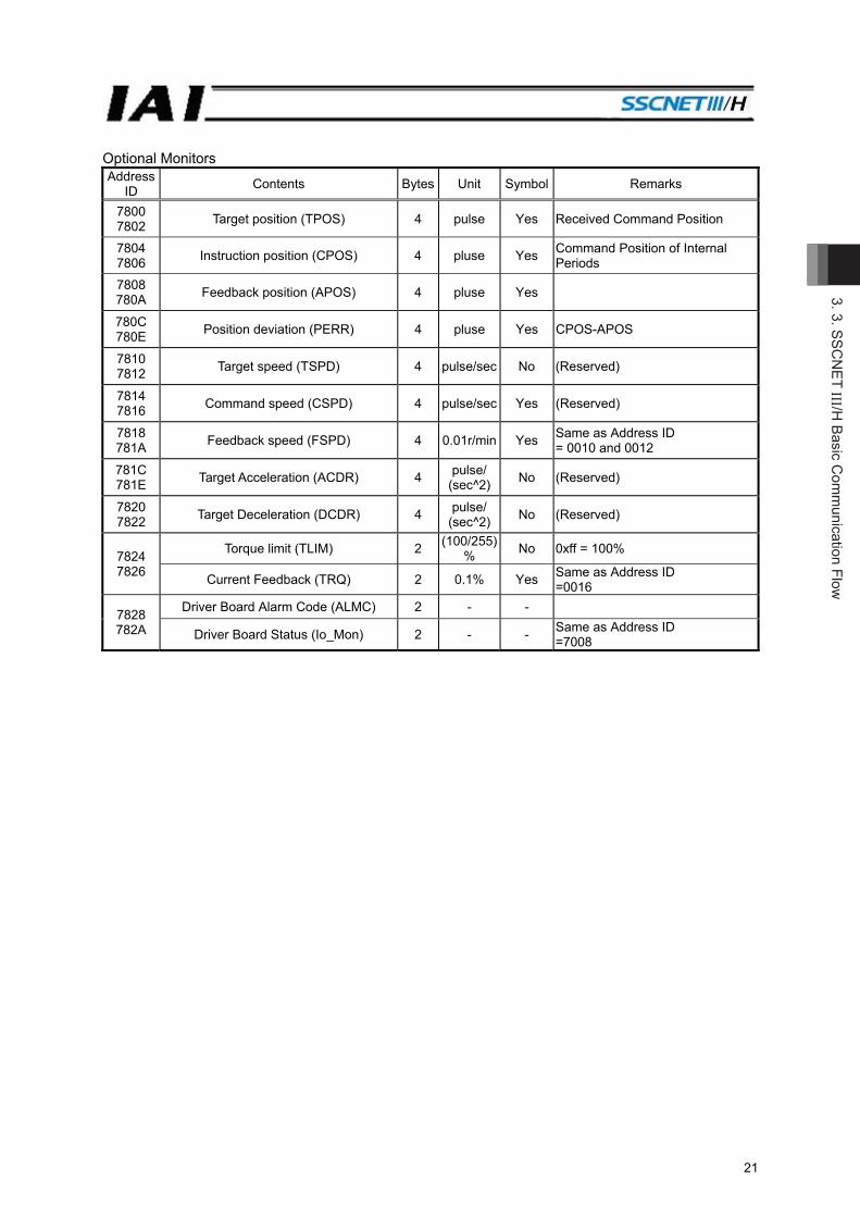
Optional Monitors Address
ID Contents Bytes Unit Symbol Remarks
7800 7802 Target position (TPOS) 4 pulse Yes Received Command Position
7804 7806 Instruction position (CPOS) 4 pluse Yes Command Position of Internal
Periods 7808 780A Feedback position (APOS) 4 pluse Yes
780C 780E Position deviation (PERR) 4 pluse Yes CPOS-APOS
7810 7812 Target speed (TSPD) 4 pulse/sec No (Reserved)
7814 7816 Command speed (CSPD) 4 pulse/sec Yes (Reserved)
7818 781A Feedback speed (FSPD) 4 0.01r/min Yes Same as Address ID
= 0010 and 0012 781C 781E Target Acceleration (ACDR) 4 pulse/
(sec^2) No (Reserved)
7820 7822 Target Deceleration (DCDR) 4 pulse/
(sec^2) No (Reserved)
7824 7826
Torque limit (TLIM) 2 (100/255)% No 0xff = 100%
Current Feedback (TRQ) 2 0.1% Yes Same as Address ID =0016
7828 782A
Driver Board Alarm Code (ALMC) 2 - -
Driver Board Status (Io_Mon) 2 - - Same as Address ID =7008

3. S
SCN
ET III/H
Bas
ic C
omm
unic
atio
n Fl
ow
22
3.2.2 Transient Commands ID01 Network Object (Response Data Readout)
Transient ID Contents Remarks
0104 Registration Monitor 1 Readout Feeds back the setting values in Registration Monitor 1
0105 Registration Monitor 2 Readout Feeds back the setting values in Registration Monitor 2
0106 Registration Monitor 3 Readout Feeds back the setting values in Registration Monitor 3
0107 Registration Monitor 4 Readout Feeds back the setting values in Registration Monitor 4
ID01 Network Object (Demand Data Writing)
Transient ID Contents Remarks
0184 Registration Monitor 1 Setting Changes the setting values in Registration Monitor 1
0185 Registration Monitor 2 Setting Changes the setting values in Registration Monitor 2
0186 Registration Monitor 3 Setting Changes the setting values in Registration Monitor 3
0187 Registration Monitor 4 Setting Changes the setting values in Registration Monitor 4
ID03 Information Object (Response Data Readout)
Transient ID Contents Remarks
0301 Vendor Name
Offset 0000 : Vendor ID (0x000A:IAI) 0002 : Model code (0x2001:MCON(MSEP)) 0004, 0006 : 0
0304 Servomotor / Encoder Model Code
Offset 0000, 0002 : Driver parameters of Symbol MTYP0004, 0006 : Driver parameters of Symbol ETYP
0305 Number of Pulse per Revolution
Feeds back the number of encoder pulse in one turn of mechanical angle Offset 0000, 0002 : Driver parameters of Symbol EPLS0004, 0006 :0
0308 Monitor Data Readout Feeds back the registration monitor value of the demanded address
0310 Unit Model Name #1
‘M’‘C’‘O’‘N’‘-’‘C’ Offset 0000 : ‘M’‘C’ 0002 : ‘O’‘N’ 0004 : ‘-’‘C’
0311 Unit Model Name #2
‘S’‘N’‘0’‘0’‘0’‘0’‘0’‘0’ Offset 0000 : ‘S’‘N’ 0002 : 0 0004 : 0 0006 : 0
0312 Unit S/W Version #1
Feeds back the model code and application version of the driver in ASCII code Offset 0000, 0002 : Driver part model code 0004, 0006 : Driver part application version
3. 3. SSCN
ET III /H Basic C
omm
unication Flow
23
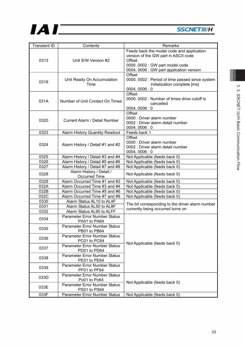
Transient ID Contents Remarks
0313 Unit S/W Version #2
Feeds back the model code and application version of the GW part in ASCII code Offset 0000 ,0002 : GW part model code 0004, 0006 : GW part application version
0319 Unit Ready On Accumulation Time
Offset 0000, 0002 : Period of time passed since system
initialization complete [ms] 0004, 0006 : 0
031A Number of Unit Contact On Times
Offset 0000, 0002 : Number of times drive cutoff is
cancelled 0004, 0006 : 0
0320 Current Alarm / Detail Number
Offset 0000 : Driver alarm number 0002 : Driver alarm detail number 0004, 0006 : 0
0323 Alarm History Quantity Readout Feeds back 1
0324 Alarm History / Detail #1 and #2
Offset 0000 : Driver alarm number 0002 : Driver alarm detail number 0004, 0006 : 0
0325 Alarm History / Detail #3 and #4 Not Applicable (feeds back 0) 0326 Alarm History / Detail #5 and #6 Not Applicable (feeds back 0) 0327 Alarm History / Detail #7 and #8 Not Applicable (feeds back 0)
0328 Alarm History / Detail / Occurred Time Not Applicable (feeds back 0)
0329 Alarm Occurred Time #1 and #2 Not Applicable (feeds back 0) 032A Alarm Occurred Time #3 and #4 Not Applicable (feeds back 0) 032B Alarm Occurred Time #5 and #6 Not Applicable (feeds back 0) 032C Alarm Occurred Time #7 and #8 Not Applicable (feeds back 0) 0330 Alarm Status AL10 to AL4F The bit corresponding to the driver alarm number
currently being occurred turns on 0331 Alarm Status AL50 to AL8F 0332 Alarm Status AL90 to ALFF
0334 Parameter Error Number Status PA01 to PA64
Not Applicable (feeds back 0)
0335 Parameter Error Number Status PB01 to PB64
0336 Parameter Error Number Status PC01 to PC64
0337 Parameter Error Number Status PD01 to PD64
0338 Parameter Error Number Status PE01 to PE64
0339 Parameter Error Number Status PF01 to PF64
033D Parameter Error Number Status Po01 to Po64 Not Applicable (feeds back 0)
033E Parameter Error Number Status PS01 to PS64
033F Parameter Error Number Status Not Applicable (feeds back 0)
3. S
SCN
ET III/H
Bas
ic C
omm
unic
atio
n Fl
ow
24
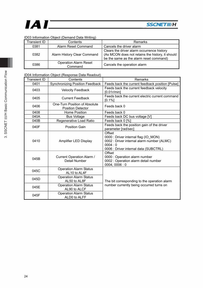
ID03 Information Object (Demand Data Writing) Transient ID Contents Remarks
0381 Alarm Reset Command Cancels the driver alarm
0382 Alarm History Clear Command Clears the driver alarm occurrence history (As MCON does not retains the history, it should be the same as the alarm reset command)
0386 Operation Alarm Reset Command Cancels the operation alarm
ID04 Information Object (Response Data Readout)
Transient ID Contents Remarks 0401 Synchronizing Position Feedback Feeds back the current feedback position [Pulse]
0403 Velocity Feedback Feeds back the current feedback velocity [0.01r/min]
0405 Current Feedback Feeds back the current electric current command [0.1%]
0406 One-Turn Position of Absolute Position Detector Feeds back 0
0408 Home Position Feeds back 0 040A Bus Voltage Feeds back DC bus voltage [V] 040B Regenerative Load Ratio Feeds back 0 [%]
040F Position Gain Feeds back the position gain of the driver parameter [rad/sec]
0410 Amplifier LED Display
Offset 0000 : Driver internal flag (IO_MON) 0002 : Driver internal alarm number (ALMC) 0004 : 0 0006 : Driver internal data (SUBCTRL)
045B Current Operation Alarm / Detail Number
Offset 0000 : Operation alarm number 0002 : Operation alarm detail number 0004, 0006 : 0
045C Operation Alarm Status AL10 to AL4F
The bit corresponding to the operation alarm number currently being occurred turns on
045D Operation Alarm Status AL50 to AL8F
045E Operation Alarm Status AL90 to ALCF
045F Operation Alarm Status ALD0 to ALFF
4. Cautions in Actuator O
peration
25
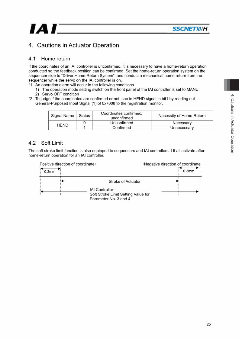
4. Cautions in Actuator Operation 4.1 Home return If the coordinates of an IAI controller is unconfirmed, it is necessary to have a home-return operation conducted so the feedback position can be confirmed. Set the home-return operation system on the sequencer side to “Driver Home-Return System”, and conduct a mechanical home return from the sequencer while the servo on the IAI controller is on. *1 An operation alarm will occur in the following conditions
1) The operation mode setting switch on the front panel of the IAI controller is set to MANU 2) Servo OFF condition
*2 To judge if the coordinates are confirmed or not, see in HEND signal in bit1 by reading out General-Purposed Input Signal (1) of 0x7008 to the registration monitor.
Signal Name Status Coordinates confirmed/ unconfirmed Necessity of Home-Return
HEND 0 Unconfirmed Necessary 1 Confirmed Unnecessary
4.2 Soft Limit The soft stroke limit function is also equipped to sequencers and IAI controllers. I It all activate after home-return operation for an IAI controller.
Positive direction of coordinate← →Negative direction of coordinate
0.3mm 0.3mm
Stroke of Actuator
IAI Controller Soft Stroke Limit Setting Value for Parameter No. 3 and 4
5. IA
I Con
trolle
r Par
amet
ers
26
5. IAI Controller Parameters It is the data to operate an IAI controller applicable for SSCNET /H. Set the parameters considering the system and applications. When a change is required to the parameters, make sure to back up the data before the change so the settings can be returned anytime. With using PC software, it is able to store the backup to the PC. “Touch Panel Teaching” is capable for backup to a memory card. After an edit is made on the parameters, it is written in FeRAM. The content of edit can be activated after the reboot of the power. Note that the change will not be valid only by writing it in a teaching tool such as the PC software. [Refer to sections of parameters in MCON controller instruction manual provided separately]
Warning: Establishment of parameter setting gives a great influence to operation. Wrongly established setting could cause not only an operation error or malfunction, but also it is very dangerous. Settings at the delivery enable the product to operate standardly. When having a change or setting considering suitability to the system, make sure to understand well about how to control the controller. Please contact us if you have anything unclear. Do not turn off the power to the controller during the parameter writing.

5. IAI Controller Param
eters
27
5.1 Parameter List Each axis number has the following parameter table. Have the setting and checking on each axis number. The categories in the table below indicate whether parameters should be set or not. There are five categories as follows: A: Check the settings before use. B: Use parameters of this category depending on their uses. C: Use parameters of this category with the settings at shipments leaving unchanged as a rule.
Normally they may not be set. D: Parameters of the category are set at shipment in accordance with the specification of the actuator.
Normally they may not be set. E: Parameters of the category are exclusively used by us for convenience of production. Changing
their settings may not only cause the actuator to operate improperly but also to be damaged. So, never change the setting of the parameters.
Category do not appear on the teaching tool. Also, the unused parameter numbers are not mentioned in the list.
Parameter List (1/3)
No.
Cat
egor
y
Name Symbol Unit (Note 1) Input Range Default Factory
Setting
Applicable Motor
Type (Note 3) RelevantSections
A P D
1 B Zone 1+ ZONM mm (deg) -9999.99 to 9999.99 Actual stroke on +
side (Note 2) ○ ○ ○
Refer to MCON
instruction manual
2 B Zone 1- ZONL mm (deg) -9999.99 to 9999.99 Actual stroke on -
side (Note 2) ○ ○ ○
3 A Soft limit+ LIMM mm (deg) -9999.99 to 9999.99 Actual stroke on +
side (Note 2) ○ ○ ○
4 A Soft limit- LIML mm (deg) -9999.99 to 9999.99 Actual stroke on -
side (Note 2) ○ ○ ○
5 D Home return direction ORG - 0: Reverse, 1: Normal In accordance with actuator (Note 2) ○ ○ ○
7 C Servo gain number PLGO - 0 to 31 In accordance with actuator (Note 2) ○ ○ ○
9 B Default acceleration/deceleration ACMD G
0.01 to Actuator's max. acceleration/
deceleration
Rated actuator's acceleration/ Deceleration (Note 2)
○ ○ ○
10 B Default positioning width INP mm (deg)
Actuator's min. resolution to 999.99
In accordance with actuator (Note 2) ○ ○ ○
12 B Current limitation at positioning stop SPOW % 0 to 70 In accordance with
actuator (Note 2) - ○ -
13 C Current-limiting value during home return ODPW % 0 to 100 In accordance with
actuator (Note 2) - ○ -
0 to 300 ○ - ○
18 E Home position check sensor input polarity LS - 0 to 2 In accordance with
actuator (Note 2) ○ ○ -
22 C Home return offset level OFST mm (deg) 0.00 to 9999.99 In accordance with
actuator (Note 2) ○ ○ ○
23 B Zone 2+ ZNM2 mm (deg) -9999.99 to 9999.99 Actual stroke on +
side (Note 2) ○ ○ ○
24 B Zone 2- ZNL2 mm (deg) -9999.99 to 9999.99 Actual stroke on -
side (Note 2) ○ ○ ○
28 B Default movement direction for excitation-phase signal detection
PHSP - 0: Reverse, 1: Normal In accordance with actuator (Note 2) ○ ○ -
29 B Excitation-phase signal detection time PHSP msec
1 to 999 10 - ○ - 50 to 999 128 ○ - -
Note 1 The unit (deg) is for rotary actuator and lever type gripper. It is displayed in [mm] in the teaching tools. Note 2 The setting values vary in accordance with the specification of the actuator. At shipment, the parameters
are set in accordance with the specification. Note 3 A: AC Servo motor type, P: Pulse motor type, D: DC Servo motor type

5. IA
I Con
trolle
r Par
amet
ers
28
Parameter List (2/3)
No.
Cat
egor
y
Name Symbol Unit (Note 1) Input Range Default Factory
Setting
Applicable Motor
Type (Note 3) RelevantSections
A P D
30
B Excitation detection type PHSP - 0: Conventional method1: New method 1 2: New method 2
1 - ○ -
Refer to MCON
instruction manual
B Pole sensing type PHSP - 0: Current control 1: Distance control 1 2: Distance control 2
1 ○ - -
31 C Speed loop proportional gain VLPG - 1 to 27661 In accordance with actuator (Note 2) ○ ○ ○
32 C Speed loop integral gain VLPT - 1 to 217270 In accordance with actuator (Note 2) ○ ○ ○
33 C Torque filter time constant TRQF - 0 to 2500 In accordance with actuator (Note 2) ○ ○ ○
35 C Safety speed SAFV mm/s(deg/s)
1 to 250 (maximum speed for the actuators
with 250 or less) 100 ○ ○ ○
43 B Home position check sensor input polarity HMC -
0: Sensor not used 1: a contact 2: b contact
In accordance with actuator (Note 2) ○ ○ -
53 B Default stop mode HSTP - 0 to 4 0 (Unused) - ○ -
54 C Current control band number CLPF - 0 to 15 In accordance with actuator (Note 2) ○ - ○
62 B Pulse count direction FPIO -
0: Motor Forward Rotation
1: Motor Reverse Rotation
In accordance with actuator (Note 2) ○ ○ ○
65 B Electronic gear numerator CNUM - 1 1 ○ ○ ○ 66 B Electronic gear denominator CDEN - 1 to 4096 1 ○ ○ ○
71 B Position feed forward gain PLFG - 0 to 100 0 ○ ○ - 50 - - ○
77 D Ball screw lead length LEAD mm (deg) 0.01 to 999.99 In accordance with
actuator (Note 2) ○ ○ ○
83 B Absolute unit ETYP - 0: Not used 1: Used
In accordance with specification at order accepted
○ ○ -
88 D Software limit margin SLMA mm 0 to 9999.99 0 ○ ○ ○
91 C Current limit value at stopping due to miss-pressing
FSTP -
0: Current limiting value at stop
1: Current limit value during pressing
0 ○ ○ ○
110 B Stop method at servo OFF PSOF - 0: Sudden stop 1: Deceleration and stop 0 ○ ○ ○
112 B Monitoring mode selection monitoring period FMNT -
0: Unused 1: Monitor Function 1 2: Monitor Function 2 3: Monitor Function 3
1 ○ ○ ○
113 B Monitoring period FMNT msec 1 to 60000 1 ○ ○ ○
120 C Servo gain number 1 PLG1 - 0 to 31 In accordance with actuator (Note 2) ○ - -
121 C Position feed forward gain 1 PLF1 - 0 to 100 In accordance with actuator (Note 2) ○ - -
122 C Speed loop proportional gain 1 VLG1 - 1 to 99999999 In accordance with
actuator (Note 2) ○ - -
123 C Speed loop integral gain 1 VLT1 - 1 to 99999999 In accordance with actuator (Note 2) ○ - -
124 C Torque filter time constant 1 TRF1 - 0 to 2500 In accordance with actuator (Note 2) ○ - -
Note 1 The unit (deg) is for rotary actuator and lever type gripper. It is displayed in [mm] in the teaching tools. Note 2 The setting values vary in accordance with the specification of the actuator. At shipment, the parameters
are set in accordance with the specification. Note 3 A: AC Servo motor type, P: Pulse motor type, D: DC Servo motor type
5. IAI Controller Param
eters
29
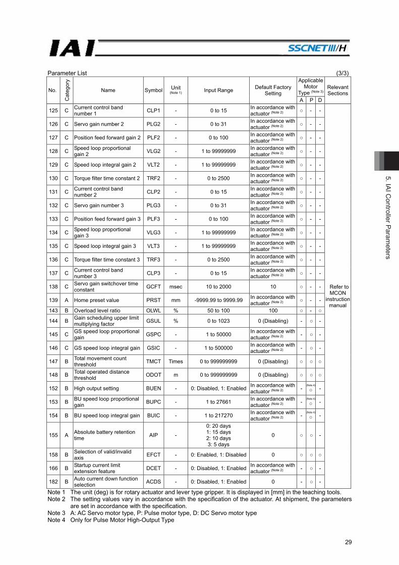
Parameter List (3/3)
No.
Cat
egor
y
Name Symbol Unit (Note 1) Input Range Default Factory
Setting
Applicable Motor
Type (Note 3) RelevantSections
A P D
125 C Current control band number 1 CLP1 - 0 to 15 In accordance with
actuator (Note 2) ○ - -
Refer to MCON
instruction manual
126 C Servo gain number 2 PLG2 - 0 to 31 In accordance with actuator (Note 2) ○ - -
127 C Position feed forward gain 2 PLF2 - 0 to 100 In accordance with actuator (Note 2) ○ - -
128 C Speed loop proportional gain 2 VLG2 - 1 to 99999999 In accordance with
actuator (Note 2) ○ - -
129 C Speed loop integral gain 2 VLT2 - 1 to 99999999 In accordance with actuator (Note 2) ○ - -
130 C Torque filter time constant 2 TRF2 - 0 to 2500 In accordance with actuator (Note 2) ○ - -
131 C Current control band number 2 CLP2 - 0 to 15 In accordance with
actuator (Note 2) ○ - -
132 C Servo gain number 3 PLG3 - 0 to 31 In accordance with actuator (Note 2) ○ - -
133 C Position feed forward gain 3 PLF3 - 0 to 100 In accordance with actuator (Note 2) ○ - -
134 C Speed loop proportional gain 3 VLG3 - 1 to 99999999 In accordance with
actuator (Note 2) ○ - -
135 C Speed loop integral gain 3 VLT3 - 1 to 99999999 In accordance with actuator (Note 2) ○ - -
136 C Torque filter time constant 3 TRF3 - 0 to 2500 In accordance with actuator (Note 2) ○ - -
137 C Current control band number 3 CLP3 - 0 to 15 In accordance with
actuator (Note 2) ○ - -
138 C Servo gain switchover time constant GCFT msec 10 to 2000 10 ○ - -
139 A Home preset value PRST mm -9999.99 to 9999.99 In accordance with actuator (Note 2) ○ - -
143 B Overload level ratio OLWL % 50 to 100 100 ○ - ○
144 B Gain scheduling upper limit multiplying factor GSUL % 0 to 1023 0 (Disabling) - ○ -
145 C GS speed loop proportional gain GSPC - 1 to 50000 In accordance with
actuator (Note 2) - ○ -
146 C GS speed loop integral gain GSIC - 1 to 500000 In accordance with actuator (Note 2) - ○ -
147 B Total movement count threshold TMCT Times 0 to 999999999 0 (Disabling) ○ ○ ○
148 B Total operated distance threshold ODOT m 0 to 999999999 0 (Disabling) ○ ○ ○
152 B High output setting BUEN - 0: Disabled, 1: Enabled In accordance with actuator (Note 2) -
(Note 4) ○ -
153 B BU speed loop proportional gain BUPC - 1 to 27661 In accordance with
actuator (Note 2) - (Note 4) ○ -
154 B BU speed loop integral gain BUIC - 1 to 217270 In accordance with actuator (Note 2) -
(Note 4) ○ -
155 A Absolute battery retention time AIP -
0: 20 days 1: 15 days 2: 10 days 3: 5 days
0 ○ ○ -
158 B Selection of valid/invalid axis EFCT - 0: Enabled, 1: Disabled 0 ○ ○ ○
166 B Startup current limit extension feature DCET - 0: Disabled, 1: Enabled In accordance with
actuator (Note 2) - ○ -
182 B Auto current down function selection ACDS - 0: Disabled, 1: Enabled 0 - ○ -
Note 1 The unit (deg) is for rotary actuator and lever type gripper. It is displayed in [mm] in the teaching tools. Note 2 The setting values vary in accordance with the specification of the actuator. At shipment, the parameters
are set in accordance with the specification. Note 3 A: AC Servo motor type, P: Pulse motor type, D: DC Servo motor type Note 4 Only for Pulse Motor High-Output Type
6. T
roub
lesh
ootin
g
30
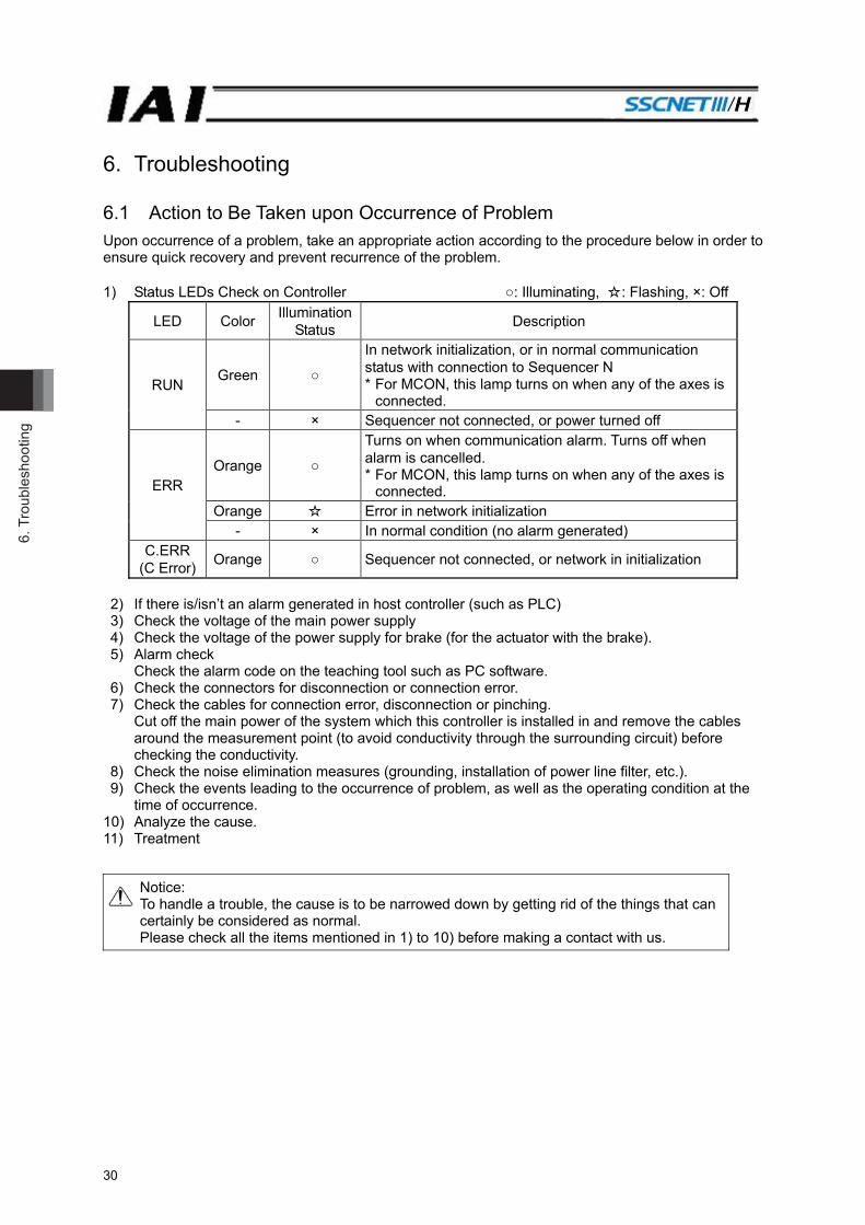
6. Troubleshooting 6.1 Action to Be Taken upon Occurrence of Problem Upon occurrence of a problem, take an appropriate action according to the procedure below in order to ensure quick recovery and prevent recurrence of the problem. 1) Status LEDs Check on Controller ○: Illuminating, ☆: Flashing, ×: Off
LED Color Illumination Status Description
RUN Green ○
In network initialization, or in normal communication status with connection to Sequencer N * For MCON, this lamp turns on when any of the axes is
connected. - × Sequencer not connected, or power turned off
ERR Orange ○
Turns on when communication alarm. Turns off when alarm is cancelled. * For MCON, this lamp turns on when any of the axes is
connected. Orange ☆ Error in network initialization
- × In normal condition (no alarm generated) C.ERR
(C Error) Orange ○ Sequencer not connected, or network in initialization
2) If there is/isn’t an alarm generated in host controller (such as PLC) 3) Check the voltage of the main power supply 4) Check the voltage of the power supply for brake (for the actuator with the brake). 5) Alarm check
Check the alarm code on the teaching tool such as PC software. 6) Check the connectors for disconnection or connection error. 7) Check the cables for connection error, disconnection or pinching.
Cut off the main power of the system which this controller is installed in and remove the cables around the measurement point (to avoid conductivity through the surrounding circuit) before checking the conductivity.
8) Check the noise elimination measures (grounding, installation of power line filter, etc.). 9) Check the events leading to the occurrence of problem, as well as the operating condition at the
time of occurrence. 10) Analyze the cause. 11) Treatment
Notice: To handle a trouble, the cause is to be narrowed down by getting rid of the things that can certainly be considered as normal. Please check all the items mentioned in 1) to 10) before making a contact with us.
6. Troubleshooting
31
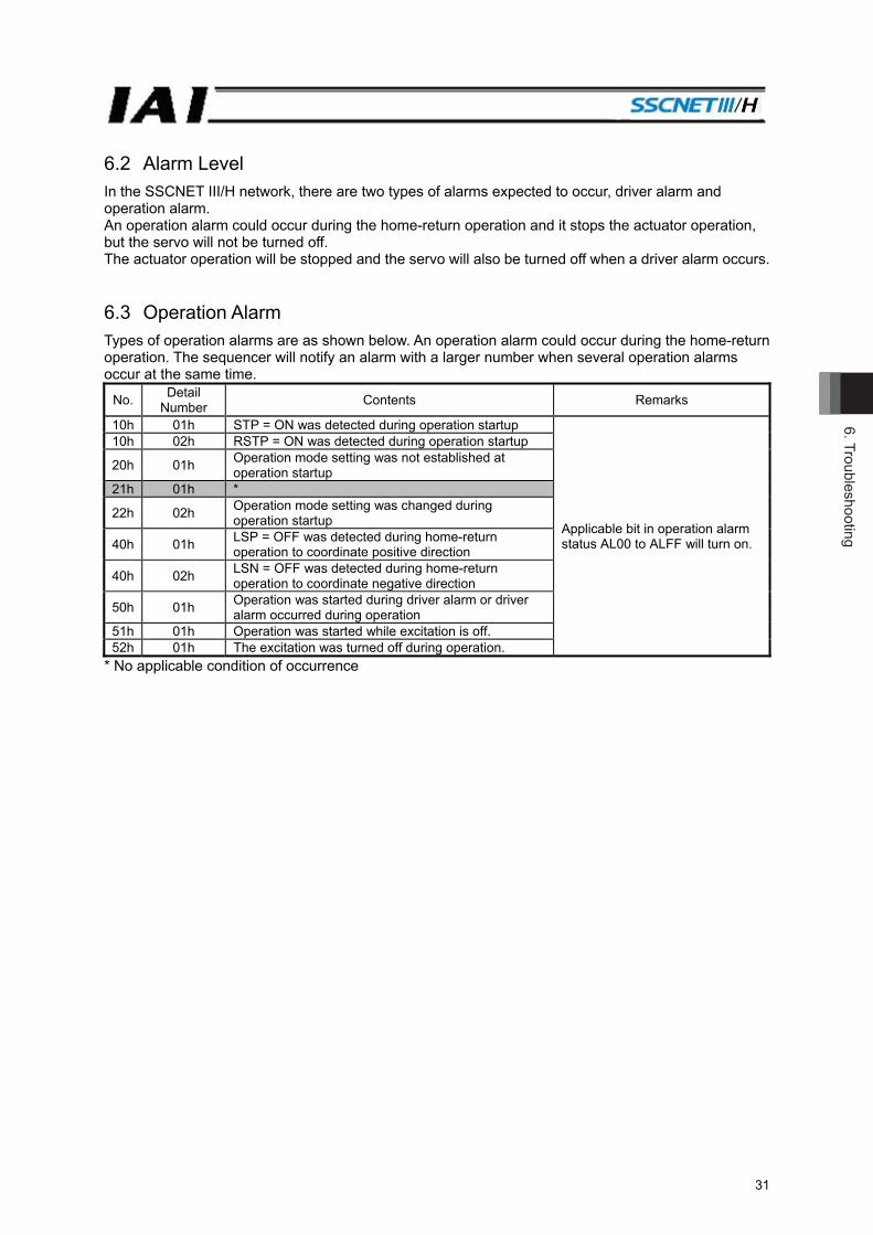
6.2 Alarm Level In the SSCNET III/H network, there are two types of alarms expected to occur, driver alarm and operation alarm. An operation alarm could occur during the home-return operation and it stops the actuator operation, but the servo will not be turned off. The actuator operation will be stopped and the servo will also be turned off when a driver alarm occurs. 6.3 Operation Alarm Types of operation alarms are as shown below. An operation alarm could occur during the home-return operation. The sequencer will notify an alarm with a larger number when several operation alarms occur at the same time.
No. Detail Number Contents Remarks
10h 01h STP = ON was detected during operation startup
Applicable bit in operation alarm status AL00 to ALFF will turn on.
10h 02h RSTP = ON was detected during operation startup
20h 01h Operation mode setting was not established at operation startup
21h 01h *
22h 02h Operation mode setting was changed during operation startup
40h 01h LSP = OFF was detected during home-return operation to coordinate positive direction
40h 02h LSN = OFF was detected during home-return operation to coordinate negative direction
50h 01h Operation was started during driver alarm or driver alarm occurred during operation
51h 01h Operation was started while excitation is off. 52h 01h The excitation was turned off during operation.
* No applicable condition of occurrence
6. T
roub
lesh
ootin
g
32
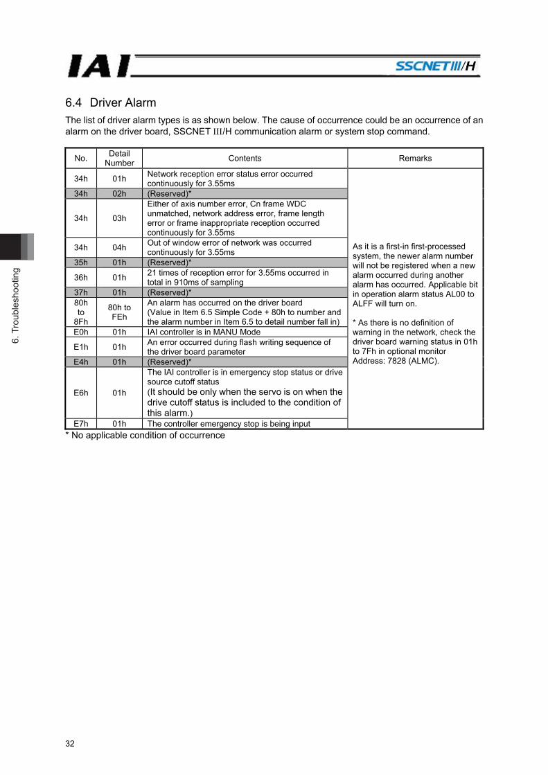
6.4 Driver Alarm The list of driver alarm types is as shown below. The cause of occurrence could be an occurrence of an alarm on the driver board, SSCNET /H communication alarm or system stop command.
No. Detail Number Contents Remarks
34h 01h Network reception error status error occurred continuously for 3.55ms
As it is a first-in first-processed system, the newer alarm number will not be registered when a new alarm occurred during another alarm has occurred. Applicable bit in operation alarm status AL00 to ALFF will turn on. * As there is no definition of warning in the network, check the driver board warning status in 01h to 7Fh in optional monitor Address: 7828 (ALMC).
34h 02h (Reserved)*
34h 03h
Either of axis number error, Cn frame WDC unmatched, network address error, frame length error or frame inappropriate reception occurred continuously for 3.55ms
34h 04h Out of window error of network was occurred continuously for 3.55ms
35h 01h (Reserved)*
36h 01h 21 times of reception error for 3.55ms occurred in total in 910ms of sampling
37h 01h (Reserved)* 80h to
8Fh
80h to FEh
An alarm has occurred on the driver board (Value in Item 6.5 Simple Code + 80h to number and the alarm number in Item 6.5 to detail number fall in)
E0h 01h IAI controller is in MANU Mode
E1h 01h An error occurred during flash writing sequence of the driver board parameter
E4h 01h (Reserved)*
E6h 01h
The IAI controller is in emergency stop status or drive source cutoff status (It should be only when the servo is on when the drive cutoff status is included to the condition of this alarm.)
E7h 01h The controller emergency stop is being input * No applicable condition of occurrence

6. Troubleshooting
33
6.5 Simple Alarm Code Simple Alarm Code Contents Numbers in the brackets ( ) show the alarm codes in Item 6.6
- Normal 2 Software reset command in servo-ON condition (090)
3
Move command during servo OFF (080) Position command in incomplete home return (082) Movement command to absolute position with home return incomplete (083)Movement command during home return operation (084)
4 Mismatched PCB (0F4)
6 Parameter data error (0A0) Parameter data error (0A1) Motor/encoder type not corresponding (0A8)
7
Z-phase position error (0B5) Z-phase detection timeout (0B6) Magnetic pole undefined (0B7) Excitation detection type (0B8) Home sensor non-detection (0BA) Home return timeout (0BE)
9
Overcurrent (0C8) Overvoltage (0C9) Overheated (0CA) Current sensor offset adjustment error (0CB) Drive source error (0D4)
11 Differential counter overflow with home return incomplete (0D5) Deviation overflow (0D8) Software stroke limit exceeded (0D9)
12
Electric angling mismatching (0B4) Servo error (0C1) Illegal control system transition command (0C5) Overvoltage on motor power (0D2) Overload (0E0) Driver logic error (0F0)
13
Encoder send error (0E4) Encoder receipt error (0E5) Encoder counter error (0E6) A-, B- and Z-phase wire breaking (0E7) A and B-phase wire breaking (0E8) BLA encoder error detection (0EB) PS-phase wire breaking (0EC) Absolute encoder error detection 1 (0ED) Absolute encoder error detection 2 (0EE) Absolute encoder error detection 3 (0EF)
14 CPU error (0FA) Internal logic error (0FC)
6. T
roub
lesh
ootin
g
34
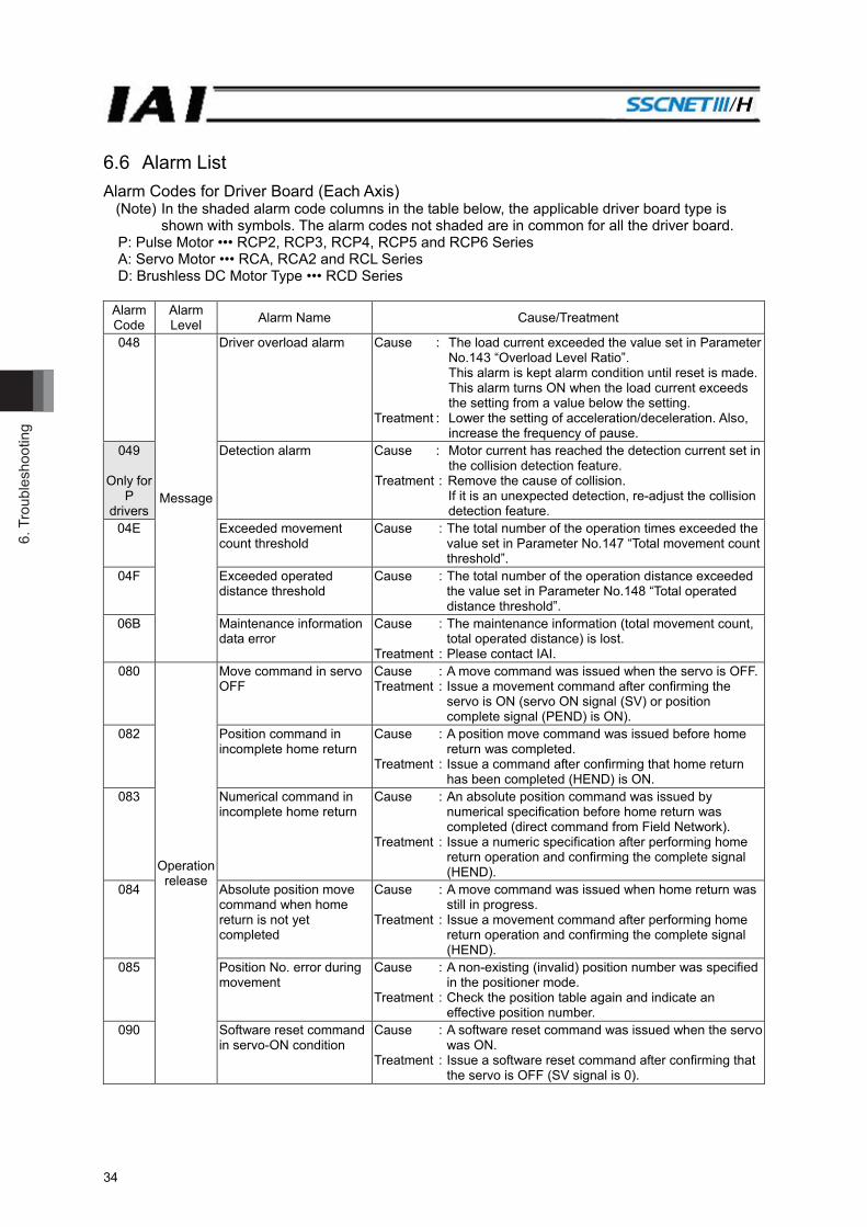
6.6 Alarm List Alarm Codes for Driver Board (Each Axis)
(Note) In the shaded alarm code columns in the table below, the applicable driver board type is shown with symbols. The alarm codes not shaded are in common for all the driver board.
P: Pulse Motor ••• RCP2, RCP3, RCP4, RCP5 and RCP6 Series A: Servo Motor ••• RCA, RCA2 and RCL Series D: Brushless DC Motor Type ••• RCD Series
Alarm Code
Alarm Level Alarm Name Cause/Treatment
048
Message
Driver overload alarm Cause : The load current exceeded the value set in Parameter No.143 “Overload Level Ratio”. This alarm is kept alarm condition until reset is made. This alarm turns ON when the load current exceeds the setting from a value below the setting.
Treatment : Lower the setting of acceleration/deceleration. Also, increase the frequency of pause.
049
Only for P
drivers
Detection alarm Cause : Motor current has reached the detection current set in the collision detection feature.
Treatment : Remove the cause of collision. If it is an unexpected detection, re-adjust the collision detection feature.
04E Exceeded movement count threshold
Cause : The total number of the operation times exceeded the value set in Parameter No.147 “Total movement count threshold”.
04F Exceeded operated distance threshold
Cause : The total number of the operation distance exceeded the value set in Parameter No.148 “Total operated distance threshold”.
06B Maintenance information data error
Cause : The maintenance information (total movement count, total operated distance) is lost.
Treatment : Please contact IAI. 080
Operation release
Move command in servo OFF
Cause : A move command was issued when the servo is OFF.Treatment : Issue a movement command after confirming the
servo is ON (servo ON signal (SV) or position complete signal (PEND) is ON).
082 Position command in incomplete home return
Cause : A position move command was issued before home return was completed.
Treatment : Issue a command after confirming that home return has been completed (HEND) is ON.
083 Numerical command in incomplete home return
Cause : An absolute position command was issued by numerical specification before home return was completed (direct command from Field Network).
Treatment : Issue a numeric specification after performing home return operation and confirming the complete signal (HEND).
084 Absolute position move command when home return is not yet completed
Cause : A move command was issued when home return was still in progress.
Treatment : Issue a movement command after performing home return operation and confirming the complete signal (HEND).
085 Position No. error during movement
Cause : A non-existing (invalid) position number was specified in the positioner mode.
Treatment : Check the position table again and indicate an effective position number.
090 Software reset command in servo-ON condition
Cause : A software reset command was issued when the servo was ON.
Treatment : Issue a software reset command after confirming that the servo is OFF (SV signal is 0).
6. Troubleshooting
35
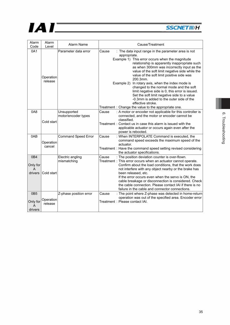
Alarm Code
Alarm Level Alarm Name Cause/Treatment
0A1
Operation release
Parameter data error Cause : The data input range in the parameter area is not appropriate.
Example 1) This error occurs when the magnitude relationship is apparently inappropriate such as when 300mm was incorrectly input as the value of the soft limit negative side while the value of the soft limit positive side was 200.3mm.
Example 2) In rotary axis, when the index mode is changed to the normal mode and the soft limit negative side is 0, this error is issued. Set the soft limit negative side to a value -0.3mm is added to the outer side of the effective stroke.
Treatment : Change the value to the appropriate one. 0A8
Cold start
Unsupported motor/encoder types
Cause : A motor or encoder not applicable for this controller is connected, and the motor or encoder cannot be classified.
Treatment : Contact us in case this alarm is issued with the applicable actuator or occurs again even after the power is rebooted.
0AB
Operation cancel
Command Speed Error Cause : When INTERPOLATE Command is executed, the command speed exceeds the maximum speed of the actuator.
Treatment : Have the command speed setting revised considering the actuator specifications.
0B4
Only for A
drivers Cold start
Electric angling mismatching
Cause : The position deviation counter is over-flown. Treatment : This error occurs when an actuator cannot operate.
Confirm about the load conditions, that the work does not interfere with any object nearby or the brake has been released, etc. If the error occurs even when the servo is ON, the cable breakage or disconnection is considered. Check the cable connection. Please contact IAI if there is no failure in the cable and connector connections.
0B5
Only for A
drivers
Operation release
Z-phase position error Cause : The point where Z-phase was detected in home-return operation was out of the specified area. Encoder error
Treatment : Please contact IAI.
6. T
roub
lesh
ootin
g
36
Alarm Code
Alarm Level Alarm Name Cause/Treatment
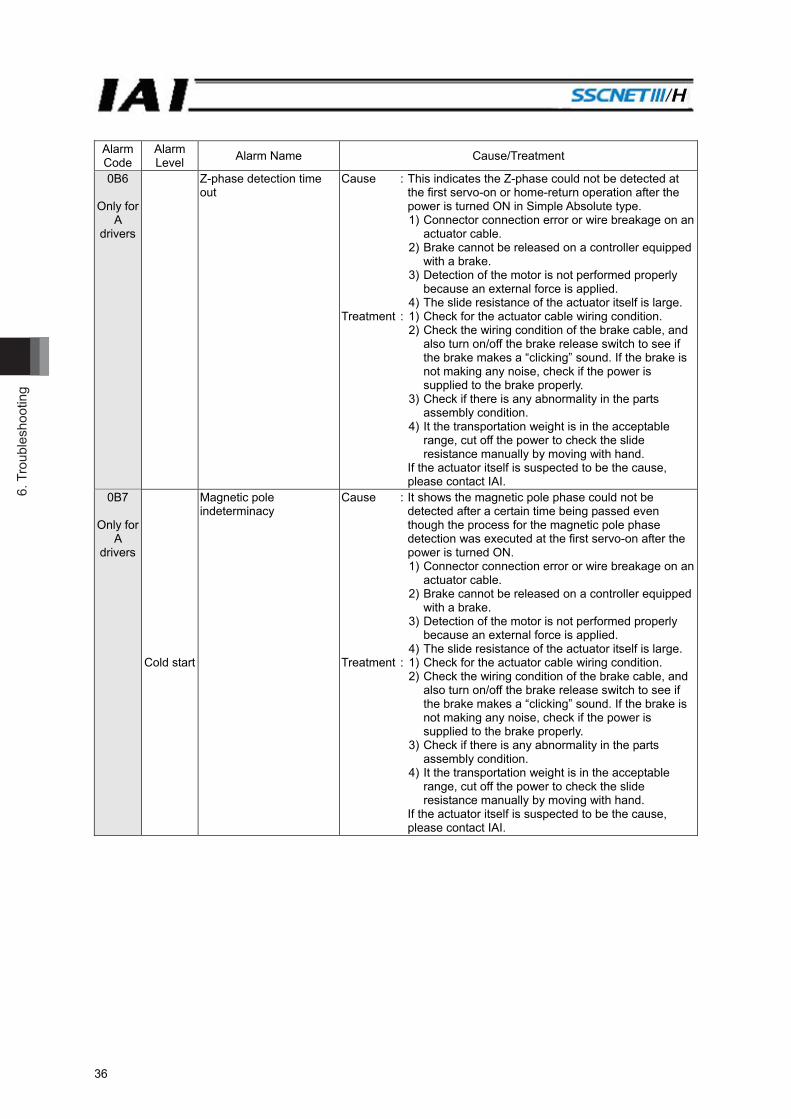
0B6
Only for A
drivers
Z-phase detection time out
Cause : This indicates the Z-phase could not be detected at the first servo-on or home-return operation after the power is turned ON in Simple Absolute type.
1) Connector connection error or wire breakage on an actuator cable.
2) Brake cannot be released on a controller equipped with a brake.
3) Detection of the motor is not performed properly because an external force is applied.
4) The slide resistance of the actuator itself is large. Treatment : 1) Check for the actuator cable wiring condition. 2) Check the wiring condition of the brake cable, and
also turn on/off the brake release switch to see if the brake makes a “clicking” sound. If the brake is not making any noise, check if the power is supplied to the brake properly.
3) Check if there is any abnormality in the parts assembly condition.
4) It the transportation weight is in the acceptable range, cut off the power to check the slide resistance manually by moving with hand.
If the actuator itself is suspected to be the cause, please contact IAI.
0B7
Only for A
drivers
Cold start
Magnetic pole indeterminacy
Cause : It shows the magnetic pole phase could not be detected after a certain time being passed even though the process for the magnetic pole phase detection was executed at the first servo-on after the power is turned ON.
1) Connector connection error or wire breakage on an actuator cable.
2) Brake cannot be released on a controller equipped with a brake.
3) Detection of the motor is not performed properly because an external force is applied.
4) The slide resistance of the actuator itself is large. Treatment : 1) Check for the actuator cable wiring condition. 2) Check the wiring condition of the brake cable, and
also turn on/off the brake release switch to see if the brake makes a “clicking” sound. If the brake is not making any noise, check if the power is supplied to the brake properly.
3) Check if there is any abnormality in the parts assembly condition.
4) It the transportation weight is in the acceptable range, cut off the power to check the slide resistance manually by moving with hand.
If the actuator itself is suspected to be the cause, please contact IAI.

6. Troubleshooting
37
Alarm Code
Alarm Level Alarm Name Cause/Treatment
0B8
Only for P
drivers
Excitement detection error
Cause : The magnetic pole phase detection is not completed after a certain time being passed even though the detection process was executed at the first servo-on after the power is turned ON.
1) Connection error or wire breakage on an actuator cable.
2) Brake is not released (when equipped with a brake).
3) Load to the motor is high due to external force. 4) Power was turned ON while touching to the
mechanical end. 5) The resistance in the actuator sliding operation is
large. Treatment : 1) Check the wiring condition of the actuator cables. 2) If an improvement can be confirmed when 24V DC,
150mA is supplied to BKRLS terminal in the external brake input connector, a malfunction of the controller can be considered. Please contact IAI.
3) Confirm that there is no error in the mechanical part assembly condition.
4) Move the slider or the rod to a point where it would not hit the mechanical end and reboot the system.
5) If the loaded weight is within the allowable range, turn the power OFF and check the resistance in sliding operation by moving the slider with hand.
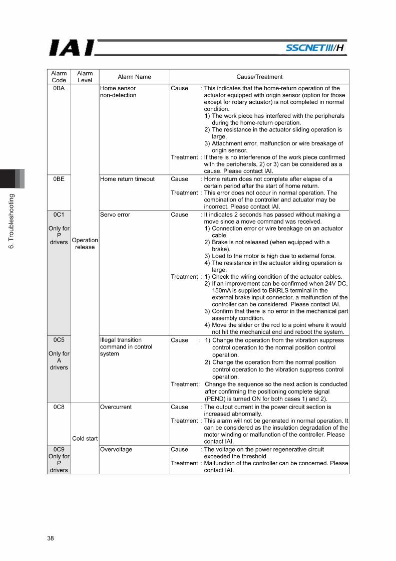
6. T
roub
lesh
ootin
g
38
Alarm Code
Alarm Level Alarm Name Cause/Treatment
0BA
Operation release
Home sensor non-detection
Cause : This indicates that the home-return operation of the actuator equipped with origin sensor (option for those except for rotary actuator) is not completed in normal condition.
1) The work piece has interfered with the peripherals during the home-return operation.
2) The resistance in the actuator sliding operation is large.
3) Attachment error, malfunction or wire breakage of origin sensor.
Treatment : If there is no interference of the work piece confirmed with the peripherals, 2) or 3) can be considered as a cause. Please contact IAI.
0BE Home return timeout Cause : Home return does not complete after elapse of a certain period after the start of home return.
Treatment : This error does not occur in normal operation. The combination of the controller and actuator may be incorrect. Please contact IAI.
0C1
Only for P
drivers
Servo error Cause : It indicates 2 seconds has passed without making a move since a move command was received.
1) Connection error or wire breakage on an actuator cable
2) Brake is not released (when equipped with a brake).
3) Load to the motor is high due to external force. 4) The resistance in the actuator sliding operation is
large. Treatment : 1) Check the wiring condition of the actuator cables. 2) If an improvement can be confirmed when 24V DC,
150mA is supplied to BKRLS terminal in the external brake input connector, a malfunction of the controller can be considered. Please contact IAI.
3) Confirm that there is no error in the mechanical part assembly condition.
4) Move the slider or the rod to a point where it would not hit the mechanical end and reboot the system.
0C5
Only for A
drivers
Illegal transition command in control system
Cause : 1) Change the operation from the vibration suppress control operation to the normal position control operation.
2) Change the operation from the normal position control operation to the vibration suppress control operation.
Treatment : Change the sequence so the next action is conducted after confirming the positioning complete signal (PEND) is turned ON for both cases 1) and 2).
0C8
Cold start
Overcurrent Cause : The output current in the power circuit section is increased abnormally.
Treatment : This alarm will not be generated in normal operation. It can be considered as the insulation degradation of the motor winding or malfunction of the controller. Please contact IAI.
0C9 Only for
P drivers
Overvoltage Cause : The voltage on the power regenerative circuit exceeded the threshold.
Treatment : Malfunction of the controller can be concerned. Please contact IAI.
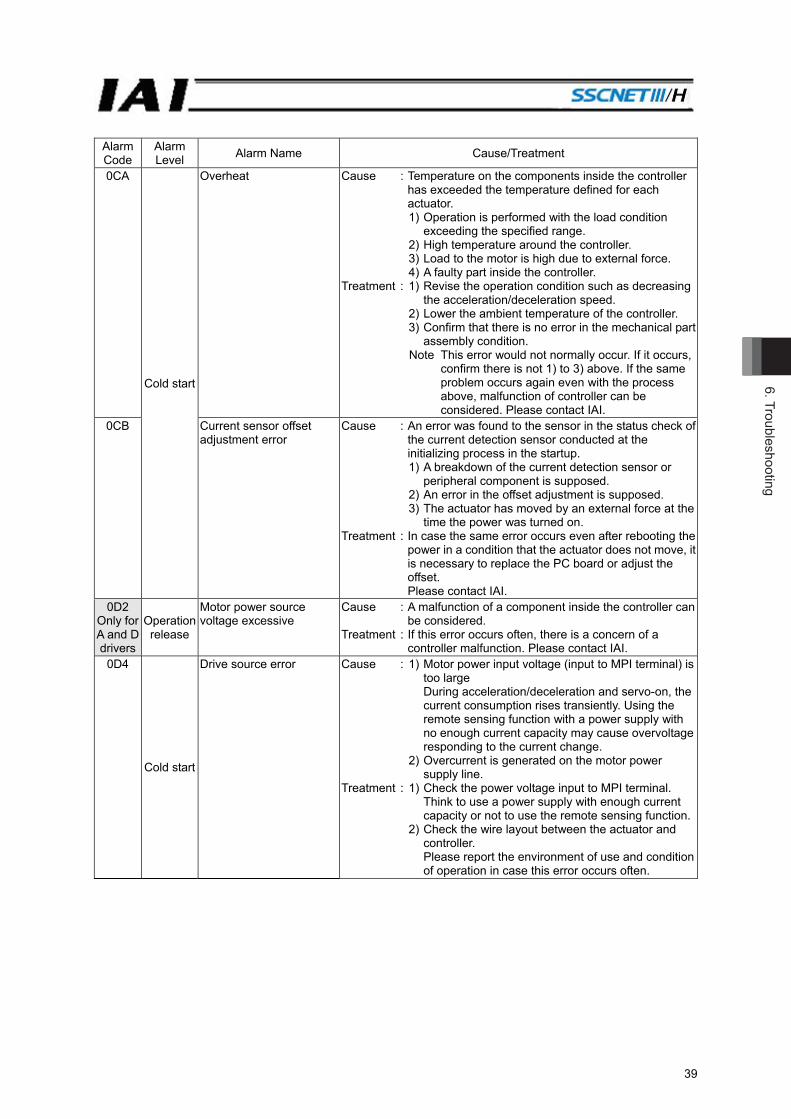
6. Troubleshooting
39
Alarm Code
Alarm Level Alarm Name Cause/Treatment
0CA
Cold start
Overheat Cause : Temperature on the components inside the controller has exceeded the temperature defined for each actuator.
1) Operation is performed with the load condition exceeding the specified range.
2) High temperature around the controller. 3) Load to the motor is high due to external force. 4) A faulty part inside the controller. Treatment : 1) Revise the operation condition such as decreasing
the acceleration/deceleration speed. 2) Lower the ambient temperature of the controller. 3) Confirm that there is no error in the mechanical part
assembly condition. Note This error would not normally occur. If it occurs,
confirm there is not 1) to 3) above. If the same problem occurs again even with the process above, malfunction of controller can be considered. Please contact IAI.
0CB
Current sensor offset adjustment error
Cause : An error was found to the sensor in the status check of the current detection sensor conducted at the initializing process in the startup.
1) A breakdown of the current detection sensor or peripheral component is supposed.
2) An error in the offset adjustment is supposed. 3) The actuator has moved by an external force at the
time the power was turned on. Treatment : In case the same error occurs even after rebooting the
power in a condition that the actuator does not move, it is necessary to replace the PC board or adjust the offset. Please contact IAI.
0D2 Only for A and D drivers
Operation release
Motor power source voltage excessive
Cause : A malfunction of a component inside the controller can be considered.
Treatment : If this error occurs often, there is a concern of a controller malfunction. Please contact IAI.
0D4
Cold start
Drive source error Cause : 1) Motor power input voltage (input to MPI terminal) is too large During acceleration/deceleration and servo-on, the current consumption rises transiently. Using the remote sensing function with a power supply with no enough current capacity may cause overvoltage responding to the current change.
2) Overcurrent is generated on the motor power supply line.
Treatment : 1) Check the power voltage input to MPI terminal. Think to use a power supply with enough current capacity or not to use the remote sensing function.
2) Check the wire layout between the actuator and controller.
Please report the environment of use and condition of operation in case this error occurs often.

6. T
roub
lesh
ootin
g
40
Alarm Code
Alarm Level Alarm Name Cause/Treatment
0D5
Only for P
drivers
Cold start
Differential counter overflow with home return incomplete
Cause : This alarm indicates that the position deviation counter has overflowed.
1) The speed dropped or stopped during JOG move due to an impact of external force, hit to the mechanical end or overload.
2) The excited-phase detection operation following the power-on is unstable.
Treatment : 1) This error occurs when the actuator cannot be operated as it is commanded. Check the load conditions such as if the work is touching to the surrounding object, or brake is properly released, and remove the cause.
2) Overload is concerned. Revise the transportable weight.
0D8
Operation release
Deviation overflow Cause : This alarm indicates that the position deviation counter has overflowed.
1) The speed dropped or the actuator stopped due to the effect of external force or overload.
2) The excited-phase detection operation following the power-on is unstable.
3) The power supply voltage dropped. 4) Servo gain number is too small
Treatment : 1) This error occurs when the actuator cannot be operated as it is commanded. Check the load conditions such as if the work is touching to the surrounding object, or brake is properly released, and remove the cause.
2) Overload can be concerned. Revise the transportable weight and redo the home-return operation.
3) Check for the source voltage. 4) Tune the servo-motor gain number.
0D9 Software stroke limit exceeded
Cause : The current position of the actuator exceeds the software stroke limit.
Treatment : Return the actuator to be within the range of the software stroke limit.
0E0
Cold start
Overload Cause : 1) The work weight exceeds the rated weight, or an external force is applied and the load increased.
2) If the actuator is equipped with a brake, the brake is not released.
3) The slide resistance of the actuator is locally high.Treatment : 1) Check the work and its surrounding area to remove
the cause. 2) If an improvement can be confirmed when 24V DC,
150mA is supplied to BKRLS terminal in the external brake input connector, a malfunction of the controller can be considered. Please contact IAI. If the error cannot be cancelled, malfunction of brake, cable breakage or controller malfunction can be considered. Please contact IAI.
3) In the case that the work can be moved by hand, move it. Then, check that there is no location where a sliding resistant is too large. Check if the installation face is distorted. When the error occurs in operation of the actuator only, Please contact IAI.
Caution Restart the operation after making sure to remove the cause. If you cannot determine that the cause is removed completely, wait for at least 30 minutes before turning ON the power to prevent the motor coil from burning.
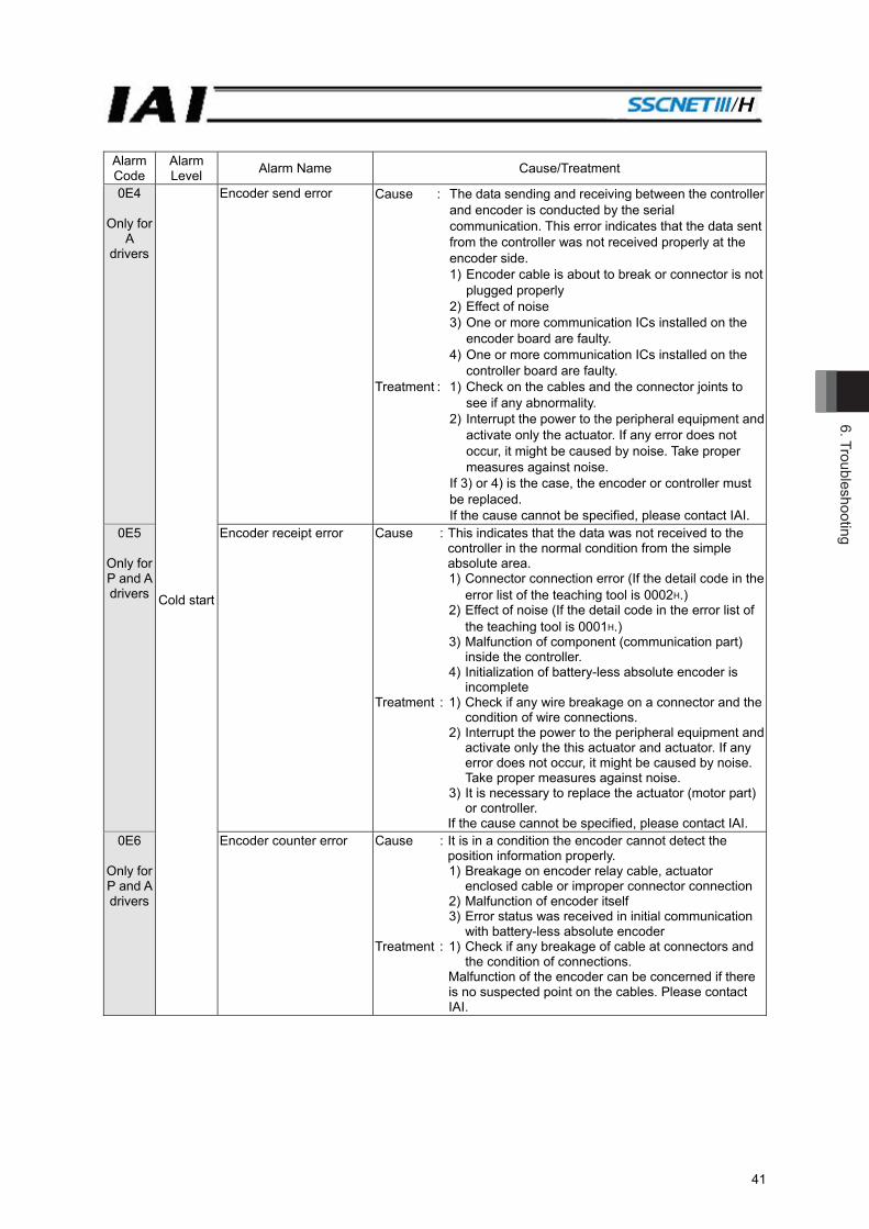
6. Troubleshooting
41
Alarm Code
Alarm Level Alarm Name Cause/Treatment
0E4
Only for A
drivers
Cold start
Encoder send error Cause : The data sending and receiving between the controller and encoder is conducted by the serial communication. This error indicates that the data sent from the controller was not received properly at the encoder side. 1) Encoder cable is about to break or connector is not
plugged properly 2) Effect of noise 3) One or more communication ICs installed on the
encoder board are faulty. 4) One or more communication ICs installed on the
controller board are faulty. Treatment : 1) Check on the cables and the connector joints to
see if any abnormality. 2) Interrupt the power to the peripheral equipment and
activate only the actuator. If any error does not occur, it might be caused by noise. Take proper measures against noise.
If 3) or 4) is the case, the encoder or controller must be replaced. If the cause cannot be specified, please contact IAI.
0E5
Only for P and A drivers
Encoder receipt error Cause : This indicates that the data was not received to the controller in the normal condition from the simple absolute area.
1) Connector connection error (If the detail code in the error list of the teaching tool is 0002H.)
2) Effect of noise (If the detail code in the error list of the teaching tool is 0001H.)
3) Malfunction of component (communication part) inside the controller.
4) Initialization of battery-less absolute encoder is incomplete
Treatment : 1) Check if any wire breakage on a connector and the condition of wire connections.
2) Interrupt the power to the peripheral equipment and activate only the this actuator and actuator. If any error does not occur, it might be caused by noise. Take proper measures against noise.
3) It is necessary to replace the actuator (motor part) or controller.
If the cause cannot be specified, please contact IAI. 0E6
Only for P and A drivers
Encoder counter error Cause : It is in a condition the encoder cannot detect the position information properly.
1) Breakage on encoder relay cable, actuator enclosed cable or improper connector connection
2) Malfunction of encoder itself 3) Error status was received in initial communication
with battery-less absolute encoder Treatment : 1) Check if any breakage of cable at connectors and
the condition of connections. Malfunction of the encoder can be concerned if there is no suspected point on the cables. Please contact IAI.

6. T
roub
lesh
ootin
g
42
Alarm Code
Alarm Level Alarm Name Cause/Treatment
0E7
Only for A
drivers
Cold start
A-, B- and Z-phase wire breaking
Cause : Encoder signals cannot be detected correctly. 1) Wire breakage or connector connection error on an
actuator cable or cable enclosed in an actuator. 2) Malfunction of encoder itself. Treatment : 1) Check if any wire breakage on a connector and the
condition of wire connections. If the cables are in the normal condition, the
malfunction of the encoder can be considered. Please contact IAI.
0E8
A- and B-phase wire breaking
Cause : Encoder signals cannot be detected correctly. 1) Wire breakage or connector connection error on an
actuator cable or cable enclosed in an actuator. 2) Malfunction of encoder itself. Treatment : 1) Check if any wire breakage on a connector and the
condition of wire connections. If the cables are in the normal condition, the
malfunction of the encoder can be considered. Please contact IAI.
0EB
Only for P and A drivers
Battery-less absolute encoder error detection
Cause : It is a condition that the battery-less absolute encoder cannot detect the position information correctly.
Treatment : Check if any wire breakage on a connector and the condition of wire connections.
If the cables are normal, faulty encoder is suspected. Please contact IAI.
0EC
Only for D
drivers
PS-phase wire breaking Cause : Encoder signals cannot be detected correctly. 1) Wire breakage or connector connection error on an
actuator cable or cable enclosed in an actuator. 2) Malfunction of encoder itself. Treatment : 1) Check if any wire breakage on a connector and the
condition of wire connections. If the cables are in the normal condition, the
malfunction of the encoder can be considered. Please contact IAI.
0ED
Only for P and A drivers
Operation release
Absolute encoder error detection 1
Cause : The current position has changed while controller was reading the absolute data or saving files.
Treatment : Avoid a condition that gives vibration to the actuator.
0EE
Only for P and A drivers
Absolute encoder error detection 2
Cause : The position data cannot be detected properly in the Battery-less absolute type or Simple absolute type encoder.
1) When the power is supplied for the first time to after the motor replacement of Battery-less absolute type or Simple absolute type (before executing absolute reset)
2) Voltage drop of absolute battery. (simple absolute type) (If the detail code in the error list of the teaching tool is 0001H.)
3) Wire breakage or connector connection error on an actuator cable or cable enclosed in an actuator or connector being removed and inserted. (If the detail code in the error list of the teaching tool is 0002H.)
4) Changed the parameters of controller. Treatment : 3) Supply the power for 72 hours or more and after
charging the battery enough, perform the absolute reset operation. If the same failure occurs often even with enough battery charge, it is considered the end of the battery life. Replace the battery.
Conduct an absolute reset for 1), 3) and 4).

6. Troubleshooting
43
Alarm Code
Alarm Level Alarm Name Cause/Treatment
0EF
Only for P and A drivers Operation
release
Absolute encoder error detection 3
Cause : The encoder for the Simple absolute type cannot detect the position information properly. (Encoder over speed error) The current position changed with a speed more than the rotation speed setting by an external cause during the power shutoff.
Treatment : Set the rotation speed to a higher speed than what currently is. If the same failure occurs again, it is necessary to have an absolute reset. [Refer to Chapter 7. Absolute Reset and Absolute Battery]
0F0
Only for A and D drivers Cold start
Driver logic error Cause : Exceeded load, parameter (motor type) mismatched, noise, malfunction of controller, etc.
Treatment : Please contact IAI.
0F4 Mismatched PCB Cause : The PCB is not applicable for the connected motor in the startup check. There is a possibility of mismatch between the actuator and controller. Check the model codes.
Treatment : Should this error occur, please contact IAI. 0F5
Operation release
Nonvolatile memory write verify error
Cause : It is verified at the data writing process to the non-volatile memory that the data inside the memory and the data to be written are matched. There was a mismatch detected in this process. (Faulty nonvolatile memory.)
Treatment : When the error is caused even when the power is re-input, please contact IAI.
0F6
Cold start
Nonvolatile memory write timeout
Cause : There is no response in the specified time duration during the data writing to the non-volatile memory. (Faulty nonvolatile memory.)
Treatment : When the error is caused even when the power is re-input, please contact IAI.
0F8 Nonvolatile memory data destroyed
Cause : Abnormal data was detected during the nonvolatile memory check after starting. (Faulty nonvolatile memory.)
Treatment : When the error is caused even when the power is re-input, please contact IAI.
0FA CPU error Cause : The CPU operation is not normal. 1) Faulty CPU.
2) Malfunction due to noise. Treatment : When the error is caused even when the power is
re-input, please contact IAI. 0FC Logic error
(Component error in controller)
Cause : The controller is not operating properly. 1) Malfunction due to the effect of noise, etc.
2) Malfunction of peripheral circuit components. Treatment : Turn the power OFF and reboot.
If the error occurs again, check for presence of noise.Also, if you have another controller, replace it and try. A recurring error with the spare controller suggests presence of noise. If the cause cannot be identified, please contact IAI.
100 to 1FF Message Alarm on teaching tool [Refer to the Instruction Manual of teaching tool.]
200 to 2FF
Operation release
Alarm on teaching tool [Refer to the Instruction Manual of teaching tool.]
300 to 3FF Cold start Alarm on teaching tool [Refer to the Instruction Manual of teaching tool.]
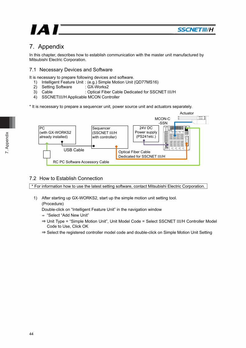
7. A
ppen
dix
44
7. Appendix In this chapter, describes how to establish communication with the master unit manufactured by Mitsubishi Electric Corporation. 7.1 Necessary Devices and Software It is necessary to prepare following devices and software.
1) Intelligent Feature Unit : (e.g.) Simple Motion Unit (QD77MS16) 2) Setting Software : GX-Works2 3) Cable : Optical Fiber Cable Dedicated for SSCNET /H 4) SSCNET/H Applicable MCON Controller
* It is necessary to prepare a sequencer unit, power source unit and actuators separately. 7.2 How to Establish Connection * For information how to use the latest setting software, contact Mitsubishi Electric Corporation.
1) After starting up GX-WORKS2, start up the simple motion unit setting tool.
(Procedure) Double-click on “Intelligent Feature Unit” in the navigation window ⇒ “Select “Add New Unit” ⇒ Unit Type = “Simple Motion Unit”, Unit Model Code = Select SSCNET /H Controller Model
Code to Use, Click OK ⇒ Select the registered controller model code and double-click on Simple Motion Unit Setting
Actuator
USB Cable Optical Fiber Cable Dedicated for SSCNET /H
RC PC Software Accessory Cable
MCON-C -SSN
24V DC Power supply (PS241etc.)
Sequencer (SSCNET/H with controller)
PC (with GX-WORKS2 already installed)

7. Appendix
45
2) Using the simple motion unit setting tool that you started up, settings are to be established by following the contents in the assistant window. First, click on “Add New” button in the simple motion module. The adding new unit window opens. Select a model code of SSCNET /H controller.
3) Click on the Step 2 System Setting button in the assistant window. In the window for connection of SSCNET /H controller and each servo amplifier, register for the number of axes connected to MCON. Double-click on a figure of each servo amplifier and the setting window opens. Set the servo amplifier series to “Driver for IAI Electric Actuator (IAI)”.
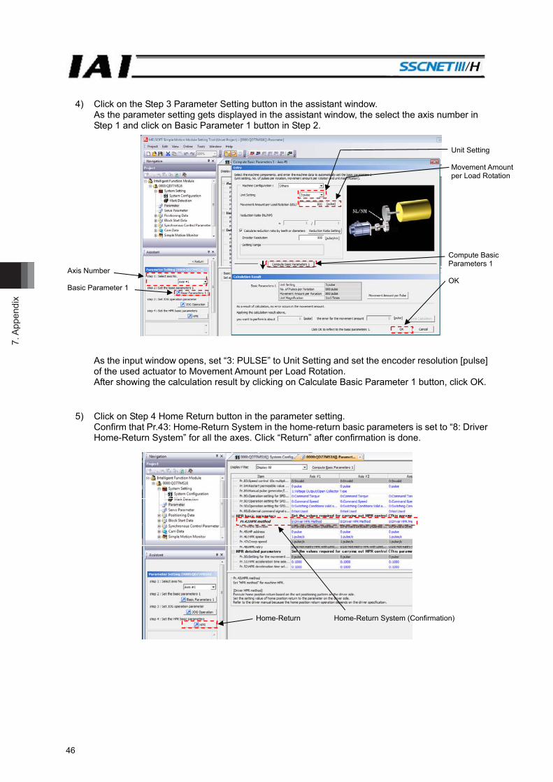
7. A
ppen
dix
46
4) Click on the Step 3 Parameter Setting button in the assistant window. As the parameter setting gets displayed in the assistant window, the select the axis number in Step 1 and click on Basic Parameter 1 button in Step 2.
As the input window opens, set “3: PULSE” to Unit Setting and set the encoder resolution [pulse] of the used actuator to Movement Amount per Load Rotation. After showing the calculation result by clicking on Calculate Basic Parameter 1 button, click OK.
5) Click on Step 4 Home Return button in the parameter setting. Confirm that Pr.43: Home-Return System in the home-return basic parameters is set to “8: Driver Home-Return System” for all the axes. Click “Return” after confirmation is done.
Axis Number Basic Parameter 1
Unit Setting Movement Amount per Load Rotation
Compute Basic Parameters 1 OK
Home-Return Home-Return System (Confirmation)
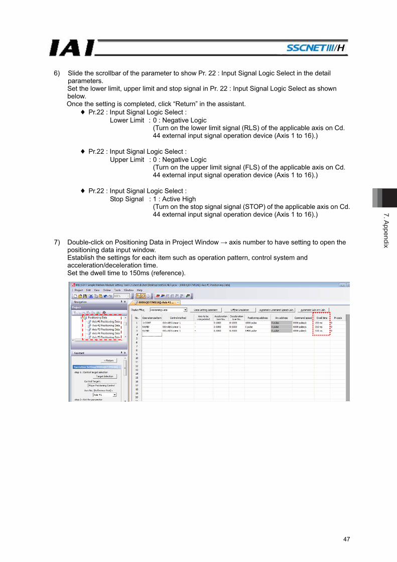
7. Appendix
47
6) Slide the scrollbar of the parameter to show Pr. 22 : Input Signal Logic Select in the detail parameters. Set the lower limit, upper limit and stop signal in Pr. 22 : Input Signal Logic Select as shown below. Once the setting is completed, click “Return” in the assistant.
♦ Pr.22 : Input Signal Logic Select : Lower Limit : 0 : Negative Logic
(Turn on the lower limit signal (RLS) of the applicable axis on Cd. 44 external input signal operation device (Axis 1 to 16).)
♦ Pr.22 : Input Signal Logic Select :
Upper Limit : 0 : Negative Logic (Turn on the upper limit signal (FLS) of the applicable axis on Cd. 44 external input signal operation device (Axis 1 to 16).)
♦ Pr.22 : Input Signal Logic Select :
Stop Signal : 1 : Active High (Turn on the stop signal signal (STOP) of the applicable axis on Cd. 44 external input signal operation device (Axis 1 to 16).)
7) Double-click on Positioning Data in Project Window → axis number to have setting to open the
positioning data input window. Establish the settings for each item such as operation pattern, control system and acceleration/deceleration time. Set the dwell time to 150ms (reference).
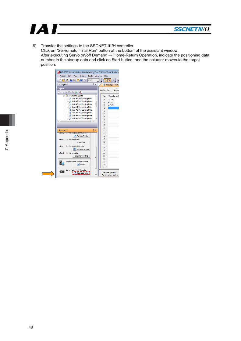
7. A
ppen
dix
48
8) Transfer the settings to the SSCNET /H controller. Click on “Servomotor Trial Run” button at the bottom of the assistant window. After executing Servo on/off Demand → Home-Return Operation, indicate the positioning data number in the startup data and click on Start button, and the actuator moves to the target position.

8. Change H
istory
48
8) Transfer the settings to the SSCNET /H controller. Click on “Servomotor Trial Run” button at the bottom of the assistant window. After executing Servo on/off Demand → Home-Return Operation, indicate the positioning data number in the startup data and click on Start button, and the actuator moves to the target position.
49
8. Change History Revision Date Revision Description
2016.04
2016.06
2016.10
2017.01
First Edition 1B Edition Correction in communication cycles, etc. 1C Edition Correction in 5.1 Parameter List 0AB Command Speed Error added in 6.6 Alarm List 1D Edition P14 to 16 Description added regarding pulse counter direction and
home-return direction Caution notes added regarding home-return operation
3.2.2 Transient Command added P47 Pr.22 : Input signal logic select settings added


Manual No.: ME0352-1D (January 2017)
The information contained in this document is subject to change without notice for purposes of product improvement.Copyright © 2017. Jan. IAI Corporation. All rights reserved.
17.01.000
Head Office: 577-1 Obane Shimizu-KU Shizuoka City Shizuoka 424-0103, JapanTEL +81-54-364-5105 FAX +81-54-364-2589
website: www.iai-robot.co.jp/
Ober der Röth 4, D-65824 Schwalbach am Taunus, GermanyTEL 06196-88950 FAX 06196-889524
SHANGHAI JIAHUA BUSINESS CENTER A8-303, 808, Hongqiao Rd. Shanghai 200030, ChinaTEL 021-6448-4753 FAX 021-6448-3992
website: www.iai-robot.com
Technical Support available in USA, Europe and China
Head Office: 2690 W. 237th Street, Torrance, CA 90505TEL (310) 891-6015 FAX (310) 891-0815
Chicago Office: 110 East State Parkway, Schaumburg, IL 60173TEL (847) 908-1400 FAX (847) 908-1399
TEL (678) 354-9470 FAX (678) 354-9471website: www.intelligentactuator.com
Atlanta Office: 1220 Kennestone Circle, Suite 108, Marietta, GA 30066
825, PhairojKijja Tower 12th Floor, Bangna-Trad RD., Bangna, Bangna, Bangkok 10260, ThailandTEL +66-2-361-4458 FAX +66-2-361-4456


![[INSERT PROJECT NAME]€¦ · Project name Project Number [Where applicable] Project Manager Project Controller Project location [Insert brief details of project location, including](https://static.documents.pub/doc/80x56/603496f741d854077e52cec0/insert-project-name-project-name-project-number-where-applicable-project-manager.jpg)
