192
3600-4062B SSD Servo Drives and Motors Installation Manual TOL-O-MATIC, INC Excellence in Motion ® ELECTRIC LINEAR MOTION PRODUCTS
3600-4062B
SSD Servo Drives and MotorsInstallation Manual
TOL-O-MATIC, INCExcellence in Motion®
ELECTRIC LINEAR MOTION PRODUCTS

© Copyright 1998Tol-O-Matic, Incorporated. All rights reserved. Axidyne and Tol-O-Matic are registered trademarks of Tol-O-Matic Incorporated. All other products or brand names are trademarks of their respective holders.11/98
J2EN
CO
DE
R
EN
CO
DE
R
DC BUS
100-240 VAC50/60 HZ
MOTOR
J1
1234567891011121314151617181920
1234567891011121314151617181920
+–
L1L2/NGNDRSTGND
RSTGN
D
ECDR +5V PWRECDR COMECDR +5V PWRECDR COMEXT 12-24EXT I/O COMMTR OUT CHNL A+MTR OUT CHNL A-MTR OUT CHNL B+MTR OUT CHNL B-MTR OUT CHNL I+MTR OUT CHNL I-EXT I/O COMAUX CNL A+AUX CHNL A-AUX CHNL B+AUX CHNL B-AUX CHNL I+AUX CHNL I-DRIVE ENABLEFAULT RESETANAL CMD +ANAL CMD -DRIVE READY +DRIVE READY -EXT 12-24I+ LIMANAL COM-I LIMRESERVEDANAL OUT 1SEL IN 1SEL IN 2
SEL OUT 1SEL OUT 2
BRAKE ENB +BRAKE ENB -
RESERVED
RESERVEDRESERVED
RESERVED
RESERVED
RESERVEDRESERVED
RESERVED
RESERVED
RESERVEDRESERVEDRESERVEDRESERVED
ST
EP
+S
TE
P -
DIR
+D
IR -
+-
SS
D
MRV MOTOR
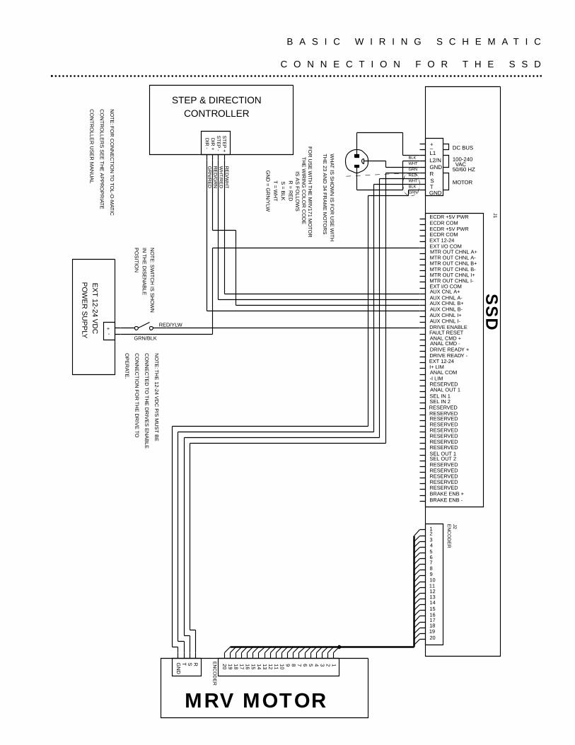
REDWHTBLKGRN
GRNWHTBLK
FO
R U
SE
WIT
H T
HE
MR
V171 M
OTO
RT
HE
WIR
ING
CO
LOR
CO
DE
IS
AS
FO
LLOW
SR
= R
ED
S =
BLK
T =
WH
T
GN
D =
GR
N/Y
LW
STEP & DIRECTIONCONTROLLER
EX
T 12-24 V
DC
PO
WE
R S
UP
PLY
RED/YLW
GRN/BLK
RE
D/W
HT
WH
T/R
ED
RE
D/G
RN
GR
N/R
ED
NO
TE
: SW
ITC
H IS
SH
OW
N
IN T
HE
DIS
EN
AB
LE
PO
SIT
ION
NO
TE
: TH
E 12-24 V
DC
P/S
MU
ST
BE
CO
NN
EC
TE
D TO
TH
E D
RIV
ES
EN
AB
LE
CO
NN
EC
TIO
N F
OR
TH
E D
RIV
E TO
OP
ER
ATE
.
NO
TE
: FO
R C
ON
NE
CT
ION
TO TO
L-O-M
ATIC
CO
NT
RO
LLER
S S
EE
TH
E A
PP
RO
PR
IATE
CO
NT
RO
LLER
US
ER
MA
NU
AL
WH
AT IS
SH
OW
N IS
FO
R U
SE
WIT
H
TH
E 23 A
ND
34 FR
AM
E M
OTO
RS
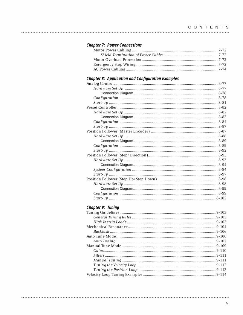
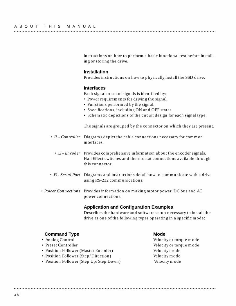
B A S I C W I R I N G S C H E M A T I C
C O N N E C T I O N F O R T H E S S D

Product Notice
Use of Axidyne SSD Servo Line DrivesSSD drives are intended for use as transistorized electronic amplifiers powering brushless servo motors in machinery. As such, they must be partof a controlled system that includes a controlling device. They are not intended to independently control a motor. Instructions in the motor andcontrol system manuals must be observed; this document does not replace those instructions.
Unless specified otherwise, SSD Line drives are intended for use in a normal industrial environment, installed in a suitable electrical cabinetwithout exposure to excessive or corrosive moisture or abnormal ambient temperatures. The exact operating conditions may be established byreferring to the data for the drive. The connection and control of drives in machinery is a skilled operation, disassembly or repair must not beattempted. In the event that a drive fails to operate correctly, contact the place of purchase for return instructions.
Safety NotesThere are some possible hazards associated with the use of drives. The following precautions should be observed. Specific Warnings and Cautionsare listed in the Preface to the manual.
Installation and Maintenance: Installation and maintenance or replacement must be carried out by suitably qualified service personnel,paying particular attention to possible electrical and mechanical hazards.
Weight: Large drives are heavy, the center of gravity may be offset and removable covers shield internal components. When handling, takeappropriate precautions and lift the equipment using permanent, fixed surfaces, such as the base; avoid lifting the device using protective covershields that may be loose. Beware of sharp edges; use protective gloves when handling such assemblies.
Flying Leads and Loose Cables: Ensure that flying leads or loose cables are suitably restrained, to prevent snagging or entanglement, orare disconnected before carrying drives with such leads or cables.
Generation: If a motor is driven mechanically, it may generate hazardous voltages which are conducted from its power input terminals to thedrive. The power connector must be suitably guarded to prevent a possible shock hazard.
Loose Drives: When running an unmounted drive, ensure that the cooling fan is adequately guarded and sufficient airflow is provided around thedrive to ensure adequate cooling. The mounting surface of the drive is a heat sink and its surface temperature may increase when the drive is operating.If a motor is connected to the drive, remove the key which otherwise could fly out and restrain the motor before applying power to the drive.
Damaged Cables: Damage to cables or connectors may cause an electrical hazard. Ensure there is no damage before energizing the system.
Supply: Drives connect to a permanent main power source; not a portable power source. Suitable fusing and circuit protection devices arerequired. Consult the instructions and adhere to local and national regulations before connecting and energizing the drive.
Safety Logic Signals: Logic signals from the drive are interruptible signals; they are removed when power is removed from the drive. Consultthe manual for information on auxiliary power connections that may be employed when these signals are used for safety purposes.
Safety Requirements: The safe incorporation of Tol-O-Matic SSD products into a machine system is the responsibility of the machinedesigner, who should comply with the local safety requirements at the place where the machine is to be used. In Europe this is likely to be theMachinery Directive, the ElectroMagnetic Compatibility Directive and the Low Voltage Directive. In the United States this is likely to be the NationalElectrical Code.
Mechanical Connection: Drives must be installed inside an electrical cabinet that provides environmental controls and protection. Installationinformation for the drive is provided in the manual and list the minimum installation requirements for the drive are provided in the manual. Motorsand controlling devices that connect to the drive should have specifications that complement the capabilities of the drive.
Motors: Motors controlled by the drive should only connect to the drive; they should not connect directly to the AC line. Use of custom motorsrequires the entering of a valid thermal time constant, otherwise the motor overload protection will not function properly.
WARNING! A SEVERE MOTOR JUMP WILL OCCUR IF THE DRIVE IS ENABLED WITH A LARGE ERROR BETWEEN THEPOSITION COMMANDED BY THE CONTROLLER AND THE ACTUAL MOTOR POSITION.To prevent this from occurring, make sure the SSD drive and controller are energized with the drive in the disabled position. Before sending anycommands from the controller to the SSD drive, make sure the SSD drive is enabled. When powering units down, disable the SSD drive prior topowering down the controller and the drive. If the actuator is to be moved while the drive and controller are powered up manual positioncorrection, disable the SSD drive, manually position the actuator, and then reset or re-zero the controller prior to re-enabling the SSD drive.
This manual provides a step-by-step approach to building a servosystem using an SSD drive. The manual is divided into chapters thatcover specific phases of the system design process; from orderingcomponents that will complement the performance of the SSD drive,to receiving, installing and verifying the drive's functionality.
Chapters in the manual include:
• Safety• Selecting Other System Components• Tol-O-Motion SSD Installation• Unpacking, Inspecting and Storing• Installation• Interfaces• Application and Configuration Examples• Tuning• Status Display• Maintenance and Troubleshooting• Options and Accessories• Cable Diagrams, Schematics, and Examples• Electromagnetic Compatibility Guidelines for Machine Design• Specifications• Warranty
i
Preface

ii
iii
Preface .....................................................................................................................i
List of Figures .......................................................................................................vii
List of Tables ..........................................................................................................ix
About This Manual .................................................................................................xiSymbols and Conventions ...................................................................................xivGraphic Symbols and Warning Classifications .................................................xvii
IntroductionSSD Microdrive Overview ....................................................................................xix
Drive Power Ratings .......................................................................................xixInterface Cables ..............................................................................................xixSSD Features ....................................................................................................xx
Chapter 1: SafetyInstalling and Using the SSD Drive ...................................................................1-1Potential Hazards.................................................................................................1-1
Voltage Potentials ..........................................................................................1-1Your Responsibilities ...........................................................................................1-2Safety Guidelines .................................................................................................1-3
Chapter 2: Unpacking, Inspecting and StoringUnpacking the Drive............................................................................................2-5Inspection Procedure ..........................................................................................2-5Testing the Unit....................................................................................................2-6Hardware Set Up ..................................................................................................2-7Drive Checkout Test.............................................................................................2-8
Initial Power-up.............................................................................................2-8Communications Verification .......................................................................2-9Initial Drive Operation................................................................................2-10
Storing the Unit..................................................................................................2-11
Chapter 3: Selecting Other System ComponentsMotors ................................................................................................................3-13Command Source ..............................................................................................3-14Serial Communications Interface.....................................................................3-14I/O Interface.......................................................................................................3-15
Analog Input ................................................................................................3-15Analog Output .............................................................................................3-15Digital Inputs ...............................................................................................3-16
Control Inputs ....................................................................................................3-16Selectable Inputs ...........................................................................................3-16
Digital Outputs ............................................................................................3-16Control Outputs..............................................................................................3-16Selectable Outputs ...................................................................................3-17
Auxiliary Encoder Interface.........................................................................3-17Encoder Inputs.........................................................................................3-17Encoder Output........................................................................................3-17
European Union Requirements........................................................................3-18
Contents

Chapter 4: Installing Tol-O-Motion SSD SoftwareHardware and Software Requirements ............................................................4-19Installation .........................................................................................................4-19Starting and Quitting Tol-O-Motion SSD.........................................................4-21
The Tol-O-Motion SSD Start-Up Screen .....................................................4-22
Chapter 5: InstallationMechanical Installation Requirements............................................................5-25Interface Connections .......................................................................................5-28Wiring ................................................................................................................5-29Electromagnetic Compatibility ........................................................................5-29
General Guidelines ......................................................................................5-29European Union EMC Directives ................................................................5-30
AC Line Filters ....................................................................................................5-31Power Wiring Diagram.......................................................................................5-33
Chapter 6: InterfacesJ1 - Controller ....................................................................................................6-36Digital I/O Power ...............................................................................................6-37
External I/O Power .......................................................................................6-37Digital Inputs ...............................................................................................6-37
Dedicated Control Circuits ........................................................................6-37Selectable Circuits.............................................................................................6-38
Input Interface Circuit Examples .....................................................................6-40Digital Outputs ............................................................................................6-42
Dedicated Relay Outputs..........................................................................6-42Selectable Transistor Outputs...................................................................6-42
READY and BRAKE/DRIVE ENABLED Circuits ..........................................6-43Output Interface Circuit Examples.............................................................6-45Analog Inputs...............................................................................................6-47
External Current Limit (I LIMIT) ................................................................6-47Command Input .......................................................................................6-47
Analog Output .............................................................................................6-49Motor Encoder Output Signal .....................................................................6-50
IOUT Signal Generation ....................................................................................6-52Auxiliary Encoder Input Types ....................................................................6-52Interface Cable Examples ............................................................................6-54
J1 Terminal Strip/Breakout Board ....................................................................6-61J2 - Encoder ..................................................................................................6-61
J3 - Serial Port.....................................................................................................6-63Serial Communications Overview....................................................................6-65
RS-232 Connections.....................................................................................6-66Single Axis RS-232 Set Up............................................................................6-66
Four Wire RS-485 Connections .........................................................................6-67Multiple Axes Four-Wire RS-485 Communications............................6-68Multiple Axes RS-232 Communications..............................................6-69
C O N T E N T S
iv
Chapter 7: Power ConnectionsMotor Power Cabling ..................................................................................7-72
Shield Termination of Power Cables ....................................................7-72Motor Overload Protection.........................................................................7-72Emergency Stop Wiring ..............................................................................7-72AC Power Cabling ........................................................................................7-74
Chapter 8: Application and Configuration ExamplesAnalog Control ...................................................................................................8-77
Hardware Set Up .........................................................................................8-77Connection Diagram.................................................................................8-78
Configuration...............................................................................................8-78Start-up ........................................................................................................8-81
Preset Controller ................................................................................................8-82Hardware Set Up..........................................................................................8-82
Connection Diagram.................................................................................8-83Configuration...............................................................................................8-84Start-up ........................................................................................................8-87
Position Follower (Master Encoder) ................................................................8-87Hardware Set Up..........................................................................................8-88
Connection Diagram.................................................................................8-89Configuration...............................................................................................8-89Start-up ........................................................................................................8-92
Position Follower (Step/Direction).................................................................. 8-93Hardware Set Up..........................................................................................8-93
Connection Diagram.................................................................................8-94System Configuration ..................................................................................8-94Start-up ........................................................................................................8-97
Position Follower (Step Up/Step Down) .........................................................8-98Hardware Set Up..........................................................................................8-98
Connection Diagram.................................................................................8-99Configuration...............................................................................................8-99Start-up ......................................................................................................8-102
Chapter 9: TuningTuning Guidelines............................................................................................9-103
General Tuning Rules ................................................................................9-103High Inertia Loads .....................................................................................9-103
Mechanical Resonance....................................................................................9-104Backlash .....................................................................................................9-106
Auto Tune Mode...............................................................................................9-106Auto Tuning ...............................................................................................9-107
Manual Tune Mode..........................................................................................9-109Gains...........................................................................................................9-110Filters ..........................................................................................................9-111Manual Tuning ..........................................................................................9-111Tuning the Velocity Loop ...........................................................................9-112Tuning the Position Loop ..........................................................................9-113
Velocity Loop Tuning Examples......................................................................9-114
v
C O N T E N T S
Chapter 10: Status DisplayStatus Indicator..............................................................................................10-117Error Messages ...............................................................................................10-117
Run Time Error Codes..............................................................................10-118Power-Up Error Codes .............................................................................10-118
Chapter 11: Maintenance and TroubleshootingMaintenance ..................................................................................................11-121
Periodic Maintenance .............................................................................11-121Cleaning ..............................................................................................11-121Cable Inspection ..................................................................................11-121Data Transfer.......................................................................................11-121
Troubleshooting.............................................................................................11-123Error Codes...............................................................................................11-123RS-232 Communication Test ..................................................................11-127Testing Digital Outputs ...........................................................................11-128Testing Digital Inputs ..............................................................................11-130Testing Analog Output.............................................................................11-130
Testing Analog Output 1 .......................................................................11-130Testing Analog Input................................................................................11-131
Testing the Current Limit Input ..............................................................11-131Testing Encoder Inputs ............................................................................11-132
Testing Encoder Inputs.........................................................................11-132
Appendix A: Options and AccessoriesSSD Drives........................................................................................................A-137Cables .............................................................................................................A-137Mating Connectors..........................................................................................A-138
Appendix B: Cable Diagrams, Schematics & ExamplesCabling Diagrams............................................................................................B-139
Appendix C: Electromagnetic Compatibility Guidelines for Machine DesignIntroduction ....................................................................................................C-143Filtering............................................................................................................C-145
AC Line Filter Selection .............................................................................C-146Grounding........................................................................................................C-147Shielding and Segregation ..............................................................................C-148
Appendix D: Dynamic Braking Resistor SelectionIntroduction ....................................................................................................D-151Dynamic Braking Equations ..........................................................................D-151Sample Calculations .......................................................................................D-152
Appendix E: Specifications.....................................................................E-155-162
Appendix F: WarrantyDefective Equipment ......................................................................................E-163Return Procedure.............................................................................................E-163
C O N T E N T S
vi
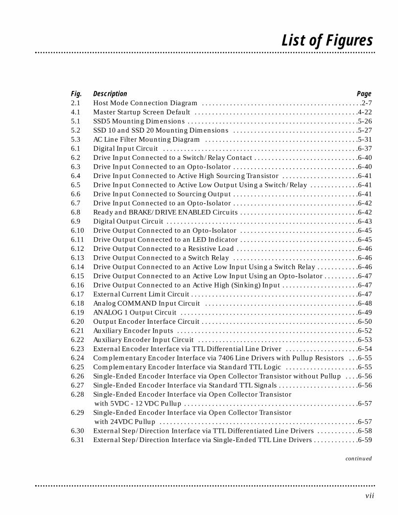
Fig. Description Page2.1 Host Mode Connection Diagram . . . . . . . . . . . . . . . . . . . . . . . . . . . . . . . . . . . . . . . . . . . . . .2-74.1 Master Startup Screen Default . . . . . . . . . . . . . . . . . . . . . . . . . . . . . . . . . . . . . . . . . . . . . . .4-225.1 SSD5 Mounting Dimensions . . . . . . . . . . . . . . . . . . . . . . . . . . . . . . . . . . . . . . . . . . . . . . . . .5-265.2 SSD 10 and SSD 20 Mounting Dimensions . . . . . . . . . . . . . . . . . . . . . . . . . . . . . . . . . . . .5-275.3 AC Line Filter Mounting Diagram . . . . . . . . . . . . . . . . . . . . . . . . . . . . . . . . . . . . . . . . . . . .5-316.1 Digital Input Circuit . . . . . . . . . . . . . . . . . . . . . . . . . . . . . . . . . . . . . . . . . . . . . . . . . . . . . . . .6-376.2 Drive Input Connected to a Switch/Relay Contact . . . . . . . . . . . . . . . . . . . . . . . . . . . . . .6-406.3 Drive Input Connected to an Opto-Isolator . . . . . . . . . . . . . . . . . . . . . . . . . . . . . . . . . . . .6-406.4 Drive Input Connected to Active High Sourcing Transistor . . . . . . . . . . . . . . . . . . . . . .6-416.5 Drive Input Connected to Active Low Output Using a Switch/Relay . . . . . . . . . . . . . .6-416.6 Drive Input Connected to Sourcing Output . . . . . . . . . . . . . . . . . . . . . . . . . . . . . . . . . . . .6-416.7 Drive Input Connected to an Opto-Isolator . . . . . . . . . . . . . . . . . . . . . . . . . . . . . . . . . . . .6-426.8 Ready and BRAKE/DRIVE ENABLED Circuits . . . . . . . . . . . . . . . . . . . . . . . . . . . . . . . . . .6-426.9 Digital Output Circuit . . . . . . . . . . . . . . . . . . . . . . . . . . . . . . . . . . . . . . . . . . . . . . . . . . . . . . .6-436.10 Drive Output Connected to an Opto-Isolator . . . . . . . . . . . . . . . . . . . . . . . . . . . . . . . . . .6-456.11 Drive Output Connected to an LED Indicator . . . . . . . . . . . . . . . . . . . . . . . . . . . . . . . . . .6-456.12 Drive Output Connected to a Resistive Load . . . . . . . . . . . . . . . . . . . . . . . . . . . . . . . . . . .6-466.13 Drive Output Connected to a Switch Relay . . . . . . . . . . . . . . . . . . . . . . . . . . . . . . . . . . . .6-466.14 Drive Output Connected to an Active Low Input Using a Switch Relay . . . . . . . . . . . .6-466.15 Drive Output Connected to an Active Low Input Using an Opto-Isolator . . . . . . . . . .6-476.16 Drive Output Connected to an Active High (Sinking) Input . . . . . . . . . . . . . . . . . . . . . .6-476.17 External Current Limit Circuit . . . . . . . . . . . . . . . . . . . . . . . . . . . . . . . . . . . . . . . . . . . . . . . .6-476.18 Analog COMMAND Input Circuit . . . . . . . . . . . . . . . . . . . . . . . . . . . . . . . . . . . . . . . . . . . .6-486.19 ANALOG 1 Output Circuit . . . . . . . . . . . . . . . . . . . . . . . . . . . . . . . . . . . . . . . . . . . . . . . . . . .6-496.20 Output Encoder Interface Circuit . . . . . . . . . . . . . . . . . . . . . . . . . . . . . . . . . . . . . . . . . . . . .6-506.21 Auxiliary Encoder Inputs . . . . . . . . . . . . . . . . . . . . . . . . . . . . . . . . . . . . . . . . . . . . . . . . . . . .6-526.22 Auxiliary Encoder Input Circuit . . . . . . . . . . . . . . . . . . . . . . . . . . . . . . . . . . . . . . . . . . . . . .6-536.23 External Encoder Interface via TTL Differential Line Driver . . . . . . . . . . . . . . . . . . . . .6-546.24 Complementary Encoder Interface via 7406 Line Drivers with Pullup Resistors . . .6-556.25 Complementary Encoder Interface via Standard TTL Logic . . . . . . . . . . . . . . . . . . . . .6-556.26 Single-Ended Encoder Interface via Open Collector Transistor without Pullup . . . .6-566.27 Single-Ended Encoder Interface via Standard TTL Signals . . . . . . . . . . . . . . . . . . . . . . .6-566.28 Single-Ended Encoder Interface via Open Collector Transistor
with 5VDC - 12 VDC Pullup . . . . . . . . . . . . . . . . . . . . . . . . . . . . . . . . . . . . . . . . . . . . . . . . . .6-576.29 Single-Ended Encoder Interface via Open Collector Transistor
with 24VDC Pullup . . . . . . . . . . . . . . . . . . . . . . . . . . . . . . . . . . . . . . . . . . . . . . . . . . . . . . . . .6-576.30 External Step/Direction Interface via TTL Differentiated Line Drivers . . . . . . . . . . . .6-586.31 External Step/Direction Interface via Single-Ended TTL Line Drivers . . . . . . . . . . . . .6-59
continued
vii
List of Figures
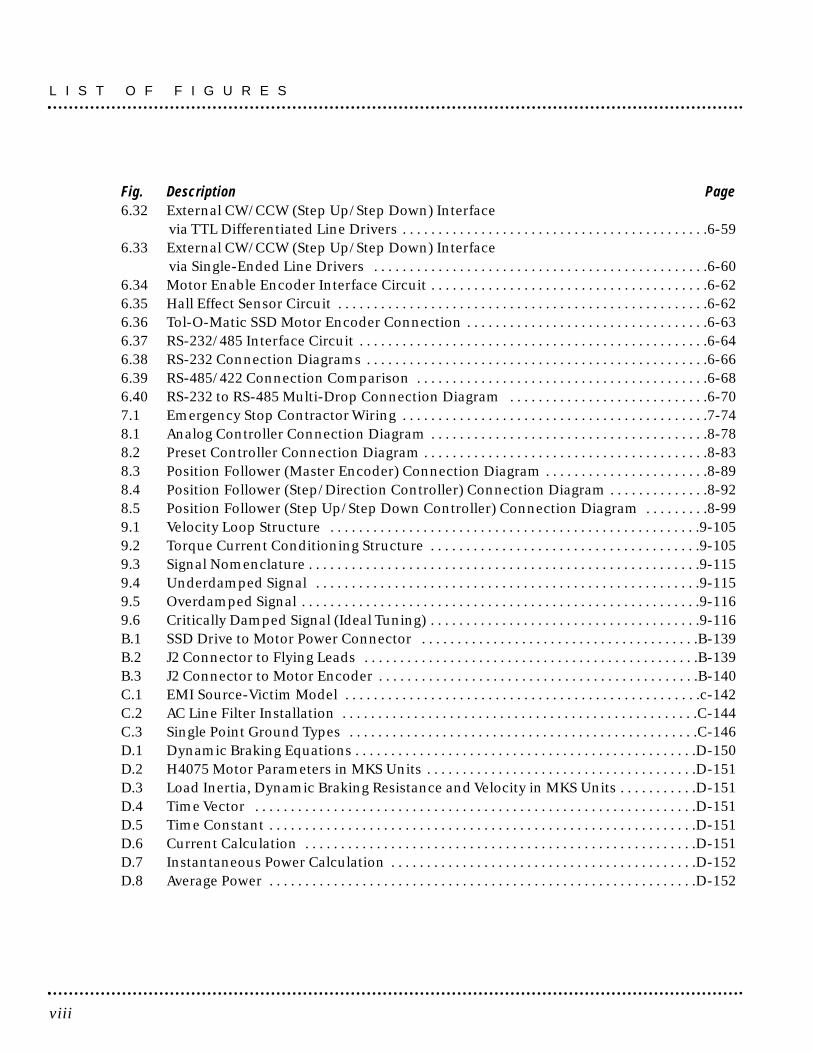
Fig. Description Page6.32 External CW/CCW (Step Up/Step Down) Interface
via TTL Differentiated Line Drivers . . . . . . . . . . . . . . . . . . . . . . . . . . . . . . . . . . . . . . . . . . .6-596.33 External CW/CCW (Step Up/Step Down) Interface
via Single-Ended Line Drivers . . . . . . . . . . . . . . . . . . . . . . . . . . . . . . . . . . . . . . . . . . . . . . .6-606.34 Motor Enable Encoder Interface Circuit . . . . . . . . . . . . . . . . . . . . . . . . . . . . . . . . . . . . . . .6-626.35 Hall Effect Sensor Circuit . . . . . . . . . . . . . . . . . . . . . . . . . . . . . . . . . . . . . . . . . . . . . . . . . . . .6-626.36 Tol-O-Matic SSD Motor Encoder Connection . . . . . . . . . . . . . . . . . . . . . . . . . . . . . . . . . .6-636.37 RS-232/485 Interface Circuit . . . . . . . . . . . . . . . . . . . . . . . . . . . . . . . . . . . . . . . . . . . . . . . . .6-646.38 RS-232 Connection Diagrams . . . . . . . . . . . . . . . . . . . . . . . . . . . . . . . . . . . . . . . . . . . . . . . .6-666.39 RS-485/422 Connection Comparison . . . . . . . . . . . . . . . . . . . . . . . . . . . . . . . . . . . . . . . . .6-686.40 RS-232 to RS-485 Multi-Drop Connection Diagram . . . . . . . . . . . . . . . . . . . . . . . . . . . .6-707.1 Emergency Stop Contractor Wiring . . . . . . . . . . . . . . . . . . . . . . . . . . . . . . . . . . . . . . . . . . .7-748.1 Analog Controller Connection Diagram . . . . . . . . . . . . . . . . . . . . . . . . . . . . . . . . . . . . . . .8-788.2 Preset Controller Connection Diagram . . . . . . . . . . . . . . . . . . . . . . . . . . . . . . . . . . . . . . . .8-838.3 Position Follower (Master Encoder) Connection Diagram . . . . . . . . . . . . . . . . . . . . . . .8-898.4 Position Follower (Step/Direction Controller) Connection Diagram . . . . . . . . . . . . . .8-928.5 Position Follower (Step Up/Step Down Controller) Connection Diagram . . . . . . . . .8-999.1 Velocity Loop Structure . . . . . . . . . . . . . . . . . . . . . . . . . . . . . . . . . . . . . . . . . . . . . . . . . . . .9-1059.2 Torque Current Conditioning Structure . . . . . . . . . . . . . . . . . . . . . . . . . . . . . . . . . . . . . .9-1059.3 Signal Nomenclature . . . . . . . . . . . . . . . . . . . . . . . . . . . . . . . . . . . . . . . . . . . . . . . . . . . . . . .9-1159.4 Underdamped Signal . . . . . . . . . . . . . . . . . . . . . . . . . . . . . . . . . . . . . . . . . . . . . . . . . . . . . .9-1159.5 Overdamped Signal . . . . . . . . . . . . . . . . . . . . . . . . . . . . . . . . . . . . . . . . . . . . . . . . . . . . . . . .9-1169.6 Critically Damped Signal (Ideal Tuning) . . . . . . . . . . . . . . . . . . . . . . . . . . . . . . . . . . . . . .9-116B.1 SSD Drive to Motor Power Connector . . . . . . . . . . . . . . . . . . . . . . . . . . . . . . . . . . . . . . .B-139B.2 J2 Connector to Flying Leads . . . . . . . . . . . . . . . . . . . . . . . . . . . . . . . . . . . . . . . . . . . . . . .B-139B.3 J2 Connector to Motor Encoder . . . . . . . . . . . . . . . . . . . . . . . . . . . . . . . . . . . . . . . . . . . . .B-140C.1 EMI Source-Victim Model . . . . . . . . . . . . . . . . . . . . . . . . . . . . . . . . . . . . . . . . . . . . . . . . . .c-142C.2 AC Line Filter Installation . . . . . . . . . . . . . . . . . . . . . . . . . . . . . . . . . . . . . . . . . . . . . . . . . .C-144C.3 Single Point Ground Types . . . . . . . . . . . . . . . . . . . . . . . . . . . . . . . . . . . . . . . . . . . . . . . . .C-146D.1 Dynamic Braking Equations . . . . . . . . . . . . . . . . . . . . . . . . . . . . . . . . . . . . . . . . . . . . . . . .D-150D.2 H4075 Motor Parameters in MKS Units . . . . . . . . . . . . . . . . . . . . . . . . . . . . . . . . . . . . . .D-151D.3 Load Inertia, Dynamic Braking Resistance and Velocity in MKS Units . . . . . . . . . . .D-151D.4 Time Vector . . . . . . . . . . . . . . . . . . . . . . . . . . . . . . . . . . . . . . . . . . . . . . . . . . . . . . . . . . . . . .D-151D.5 Time Constant . . . . . . . . . . . . . . . . . . . . . . . . . . . . . . . . . . . . . . . . . . . . . . . . . . . . . . . . . . . .D-151D.6 Current Calculation . . . . . . . . . . . . . . . . . . . . . . . . . . . . . . . . . . . . . . . . . . . . . . . . . . . . . . .D-151D.7 Instantaneous Power Calculation . . . . . . . . . . . . . . . . . . . . . . . . . . . . . . . . . . . . . . . . . . .D-152D.8 Average Power . . . . . . . . . . . . . . . . . . . . . . . . . . . . . . . . . . . . . . . . . . . . . . . . . . . . . . . . . . . .D-152
L I S T O F F I G U R E S
viii

Table Description Page5.A SSD5 Mounting Dimensions . . . . . . . . . . . . . . . . . . . . . . . . . . . . . . . . . . . . . . . . . . . . . . . .5-265.B SSD10, SSD20 Mounting Dimensions . . . . . . . . . . . . . . . . . . . . . . . . . . . . . . . . . . . . . . . .5-275.C AC Line Filters for SSD Drives . . . . . . . . . . . . . . . . . . . . . . . . . . . . . . . . . . . . . . . . . . . . . . . .5-305.D Line Filter Engineering Specifications . . . . . . . . . . . . . . . . . . . . . . . . . . . . . . . . . . . . . . . .5-326.A Controller Pin-Outs . . . . . . . . . . . . . . . . . . . . . . . . . . . . . . . . . . . . . . . . . . . . . . . . . . . . . . . .6-366.B General and Dedicated Inputs . . . . . . . . . . . . . . . . . . . . . . . . . . . . . . . . . . . . . . . . . . . . . . .6-386.C INPUT 1 and INPUT 2 Functions . . . . . . . . . . . . . . . . . . . . . . . . . . . . . . . . . . . . . . . . . . . . .6-396.D Digital Input Specifications . . . . . . . . . . . . . . . . . . . . . . . . . . . . . . . . . . . . . . . . . . . . . . . . . .6-406.E READY and BRAKE/DRIVE ENABLED Output Specifications . . . . . . . . . . . . . . . . . . . .6-436.F Selectable Output Circuits . . . . . . . . . . . . . . . . . . . . . . . . . . . . . . . . . . . . . . . . . . . . . . . . . . .6-446.G OUTPUT 1 and OUTPUT 2 Functions . . . . . . . . . . . . . . . . . . . . . . . . . . . . . . . . . . . . . . . .6-446.H Transistor Output Specifications . . . . . . . . . . . . . . . . . . . . . . . . . . . . . . . . . . . . . . . . . . . . .6-456.I Analog Inputs (1 LIMIT) . . . . . . . . . . . . . . . . . . . . . . . . . . . . . . . . . . . . . . . . . . . . . . . . . . . .6-486.J External Current Limit Input Specification . . . . . . . . . . . . . . . . . . . . . . . . . . . . . . . . . . . .6-486.K Analog Command Input . . . . . . . . . . . . . . . . . . . . . . . . . . . . . . . . . . . . . . . . . . . . . . . . . . . .6-496.L Analog Command Input Specifications . . . . . . . . . . . . . . . . . . . . . . . . . . . . . . . . . . . . . . .6-496.M Analog Outputs: ANALOG 1 and ANALOG 2 . . . . . . . . . . . . . . . . . . . . . . . . . . . . . . . . . .6-506.N Analog Output Specifications . . . . . . . . . . . . . . . . . . . . . . . . . . . . . . . . . . . . . . . . . . . . . . . .6-506.0 Motor Encoder Output Signal . . . . . . . . . . . . . . . . . . . . . . . . . . . . . . . . . . . . . . . . . . . . . . . .6-516.P Motor Encoder Output Specifications . . . . . . . . . . . . . . . . . . . . . . . . . . . . . . . . . . . . . . . .6-516.Q Motor Encoder Output Signal . . . . . . . . . . . . . . . . . . . . . . . . . . . . . . . . . . . . . . . . . . . . . . . .6-536.R Quadrative Interface Specifications . . . . . . . . . . . . . . . . . . . . . . . . . . . . . . . . . . . . . . . . . .6-546.S STEP/DIRECTION and CW/CCW (Step Up/Step Down) Interface Specifications . .6-586.T J2-Motor Encoder Connector Pin-Outs . . . . . . . . . . . . . . . . . . . . . . . . . . . . . . . . . . . . . . .6-626.U J1 Controller Pin-Outs . . . . . . . . . . . . . . . . . . . . . . . . . . . . . . . . . . . . . . . . . . . . . . . . . . . . . .6-636.V J# Serial Port Connector Pin-Outs . . . . . . . . . . . . . . . . . . . . . . . . . . . . . . . . . . . . . . . . . . . .6-657.A TB1- DC Bus and AC Power Terminal Block Connections . . . . . . . . . . . . . . . . . . . . . . .7-717.B Drive Terminals and Motor Connections . . . . . . . . . . . . . . . . . . . . . . . . . . . . . . . . . . . . . .7-727.C TN1 - AC Power Terminals . . . . . . . . . . . . . . . . . . . . . . . . . . . . . . . . . . . . . . . . . . . . . . . . . . .7-757.D AC Input Power Sizing Requirements . . . . . . . . . . . . . . . . . . . . . . . . . . . . . . . . . . . . . . . . .7-768.A Preset Binary Velocity Inputs . . . . . . . . . . . . . . . . . . . . . . . . . . . . . . . . . . . . . . . . . . . . . . . .8-829.A Velocity Loop Gains . . . . . . . . . . . . . . . . . . . . . . . . . . . . . . . . . . . . . . . . . . . . . . . . . . . . . . .9-1109.B Position Loop Gains . . . . . . . . . . . . . . . . . . . . . . . . . . . . . . . . . . . . . . . . . . . . . . . . . . . . . . .9-11010.A Run Time Error Codes . . . . . . . . . . . . . . . . . . . . . . . . . . . . . . . . . . . . . . . . . . . . . . . . . . . .10-11810.B Power-Up Error Codes . . . . . . . . . . . . . . . . . . . . . . . . . . . . . . . . . . . . . . . . . . . . . . . . . . . .10-11911.A Troubleshooting Guide . . . . . . . . . . . . . . . . . . . . . . . . . . . . . . . . . . . . . . . . . .11-124 to 11-126D.A Dynamic Braking Resistor Parameters . . . . . . . . . . . . . . . . . . . . . . . . . . . . . . . . . . . . . .D-149
ix
List of Tables

x

xi
About this Manual
Introduction
This manual provides instructions on how to setup and connect theSSD drive to a controlling device and a motor. An SSD drive mayoperate in one of several different functional modes. The hardwareconnections necessary to run the drive are detailed in this manualand basic software instructions are provided for common set upprocedures. For detailed explanation of software instructions, referto the comprehensive on-line instructions available in the Tol-O-Motion SSD Software.
The instructions in this manual detail how to install your SSD drive using Tol-O-Motion SSD software with a personal computer. If using the serial Host Command Language to control the drive,comprehensive instructions are accessible through the Host Modeicon, ?, displayed in the Tol-O-Motion SSD window.
This manual is organized into numbered chapters and alphabeticalappendices. The topics covered in each chapter and section arebriefly described. Typographical conventions, warnings and cautionsspecific to the drive, and complementary manuals are also described.
OverviewBriefly reviews major features of the SSD5, SSD10 and SSD20 drives.
FeaturesLists specific features of the SSD drives and provides a complete listof the pin-outs and signals associated with each pin.
SafetyLists general safety requirements that must be followed when install-ing or servicing the drive.
Selecting Other System ComponentsIdentifies motors and signal types that are compatible with SSD drives.
Tol-O-Motion SSD Software InstallationProvides snapshot instructions for installing, accessing and exitingSSD software.
Unpacking, Inspecting and StoringLists what should be included with the SSD drive and provides
instructions on how to perform a basic functional test before install-ing or storing the drive.
InstallationProvides instructions on how to physically install the SSD drive.
InterfacesEach signal or set of signals is identified by:• Power requirements for driving the signal.• Functions performed by the signal.• Specifications, including ON and OFF states. • Schematic depictions of the circuit design for each signal type.
The signals are grouped by the connector on which they are present.
• J1 - Controller Diagrams depict the cable connections necessary for commoninterfaces.
• J2 - Encoder Provides comprehensive information about the encoder signals,Hall Effect switches and thermostat connections available throughthis connector.
• J3 - Serial Port Diagrams and instructions detail how to communicate with a driveusing RS-232 communications.
• Power Connections Provides information on making motor power, DC bus and ACpower connections.
Application and Configuration ExamplesDescribes the hardware and software setup necessary to install thedrive as one of the following types operating in a specific mode:
Command Type Mode• Analog Control Velocity or torque mode• Preset Controller Velocity or torque mode• Position Follower (Master Encoder) Velocity mode• Position Follower (Step/Direction) Velocity mode• Position Follower (Step Up/Step Down) Velocity mode
A B O U T T H I S M A N U A L
xii

TuningProvides instructions on how to tune a drive and motor combinationusing the autotuning or manual tuning features in Tol-O-MotionSSD Software.
Status DisplayDiscusses the Status LED indicator on the front panel. Operating orError Messages accessible through a PC are explained.
Maintenance and TroubleshootingDescribes the minimal maintenance necessary with the SSD drivesand provides a comprehensive troubleshooting chart of potentialproblems and their solutions.
Options and AccessoriesLists the optional equipment available for the SSD drives. Schematicsand cabling examples are provided.
SpecificationsDetails the design and operational specifications for the SSD drivesin a tabular format.
WarrantyProvides a synopsis of the warranty coverage and how to obtainwarranty assistance.
Product SupportDescribes the product assistance available, and lists telephonenumbers for product assistance and additional on-line information.
xiii
A B O U T T H I S M A N U A L
xiv
Additional Instructions and Manuals
HOST COMMANDS AND TOL-O-MOTION SSD SOFTWARE
All SSD drives are setup through serial Host Commands. The drivesmay be configured directly through the Host Command language orindirectly through the Tol-O-Motion SSD software. Tol-O-MotionSSD is a graphical user interface that provides a visual method ofaccessing the Host Command language through the MicrosoftWindows® operating system.
All documentation for both the Host Commands and Tol-O-MotionSSD software is on-line. Host Command information is availablethrough a comprehensive on-line reference manual. Tol-O-MotionSSD information is available through Help menus. The on-linedocuments provide in-depth explanations of the Host Commandlanguage as well as the menus, windows and dialog boxes thatmake Tol-O-Motion SSD a convenient method for programmingSSD drives.
To access the Host Command Reference:• Click on the Host Command Reference icon (see left) in the Tol-
O-Motion SSD program group.
To access Tol-O-Motion SSD Help• Open Tol-O-Motion SSD by clicking on the Tol-O-Motion SSD
icon, (see left), in the Tol-O-Motion SSD group, then press the F1key.
Symbols and Conventions
TYPOGRAPHICAL AND WORDING CONVENTIONS:
Drive Set Up Text shown in this font and underlined indicates a Hot Key (keystrokecombination) to quickly access a command. Example: Choose Drive Set Up, indicates typing ALT+D followed byENTER accesses this command.
Tol-O-Motion SSD Software Text shown in this font is information to enter in a window or dialogbox.
A B O U T T H I S M A N U A L
xv
Example: Choose the icon SSD Software.
win Text in lower case bold is information to enter at a keyboard. To start Windows from the DOS prompt, type win and then pressENTER.
ALT+F4a Keys that should be pressed simultaneously are shown with a plussign (+) between the key names. This example closes the activewindow.
ALT, F, N Keys that should be pressed in sequence are shown with a comma (,)between the key names. This example opens the FILE menu andthen opens a new file.
Choose Indicates that an icon or a command is to be selected from awindow or a command box. The instruction for accessing the command icon Drive Set Up states:Choose Drive Set Up.
Select Indicates that options are to be selected from a list. The instruction for accessing or entering information states: SelectDrive Type and Motor Model from the respective list box.
Type Indicates that commands to enter in a command box. The instruction for loading Tol-O-Motion SSD software states: Typea:setup and then press ENTER.
NOTE: or TIP: Notes provide auxiliary information that is important to know. Tipsprovide hints or shortcuts that are useful. Examples: NOTE: This step assumes Tol-O-Motion SSD was
installed in the Tol-O-Motion SSD directory during setup.TIP: To disable the automatic Help display, choose the menu item Show Quick Start from the Help menu.
a.Microsoft® Windows™ reserves certain keystroke combinations to activate Windows commands.
A B O U T T H I S M A N U A L

xvi
Graphic Symbols and Warning Classifications.
Protective Conductor terminal (Earth ground)
Chassis terminal (Not a protective ground)
Risk of Electrical Shock symbol
The use of the following symbols and signal words is based on anestimation of the likelihood of exposure to the hazardous situationand what could happen as a result of exposure to the hazard.DANGER,WARNING or CAUTION require accompanying informationnotices to prevent potential personal injury and equipment damage.
Classifications include:DANGER! Indicates an imminently hazardous situation which, ifnot avoided, will result in death or serious injury. This signal word islimited to the most extreme situations.
WARNING! Indicates a potentially hazardous situation which, if notavoided, could result in death or serious injury.
Caution! Indicates a potentially hazardous situation which, if notavoided, may result in minor or moderate injury. It may be used forsituations that cause property damage only. It may also be used toalert against unsafe practices.
NOTICES
The following product safety notices appear where appropriatewithin this manual .
Danger NoticesDANGER! Only qualified electrical personnel familiar with theconstruction and operation of this equipment and the hazardsinvolved should install, adjust, operate, or service this equipment.Read and understand this manual and other applicable manuals intheir entirety before proceeding. Failure to observe this precautioncould result in severe bodily injury or loss of life.
DANGER! The user is responsible for conforming with all applicablelocal, national and international codes. Wiring practices, grounding,
!
A B O U T T H I S M A N U A L
xvii
disconnects and overcurrent protection are of particular importance.Failure to observe this precaution could result in severe bodily injuryor loss of life.
DANGER! Shielded power cables must be grounded at a minimumof one point for safety. Failure to ground a shielded power cable willresult in potentially lethal voltages on the shield and anythingconnected to it.
DANGER! DC bus capacitors may retain hazardous voltages afterinput power has been removed, but will normally discharge in severalseconds. Before working on the drive, measure the DC bus voltage toverify it has reached a safe level or wait the full time interval listed onthe warning on the front of the drive. Failure to observe this pre-caution could result in severe bodily injury or loss of life.
Warning NoticesWARNING! Perform the initial power-up with the motor shaftdisconnected from a load and the shaft key removed. Improper wiringor undiscovered shipping damage could result in undesired motormotion. Be prepared to remove power if excessive motion occurs.
WARNING! External shunt resistors connect directly to the powerbus. For safety reasons, external shunt resistors must be enclosed.
WARNING! Large leakage currents exist in AC line filters. They mustbe grounded properly before applying power. Filter capacitors retainhigh voltages after power removal. Before handling the equipment,voltages should be measured to determine safe levels prior tohandling the equipment. Failure to observe this precaution couldresult in severe bodily injury.
WARNING! A severe motor jump will occur if the drive is enabledwith a large error between the position commanded by thecontroller and the actual motor position.
WARNING! The circuits in the drive are potential sources of severeelectrical shock. Follow the safety guidelines to avoid shock.
WARNING! When using a motor without a thermal sensor, a validthermal time constant must be used. Otherwise the motor overloadprotection will not function properly.
A B O U T T H I S M A N U A L
xviii
WARNING! Rotating motor shafts can cause extensive damage andinjury. Motors must be properly guarded during testing and in thefinal installation.
WARNING! The user must provide an external, hard wired emergencystop circuit in addition to the controller circuitry. This circuit mustdisable the system in case of improper operation. Uncontrolledmachine operation may result if this procedure is not followed.Failure to observe this precaution could result in severe bodily injury.
WARNING! The user must provide an external circuit to delay output ofthe analog signal when the signal is used to perform an operation. Afterreset both analog outputs may be in an indeterminate state for a shortperiod before they stabilize at the setting stored in the PersonalityModule and selected in the Tol-O-Motion SSD I/O Configurationwindow. Failure to observe this precaution could result in severebodily injury.
WARNING! High voltage may be present on the terminals of thedrive. Remove power and disconnect the power cable before makingor removing any connection.
WARNING! Motor power connectors are for assembly purposes only.They should not be connected or disconnected while the drive ispowered.
Caution NoticesCaution! Do not tin (solder) the exposed leads on cables. Soldercontracts over time and may loosen the connection.
Caution! Ensure that encoder signals are connected properly.Incorrect connection of encoder signals will result in improperrotor position and/or incorrect commutation.
Caution! Electronic components are subject to damage by staticelectricity. Follow Electrostatic Discharge (ESD) practices whilehandling components.
Caution! If the cabinet is ventilated, use filtered or conditioned airto prevent the accumulation of dust and dirt on electroniccomponents. The air should be free of oil, corrosives, or electricallyconductive contaminates.
A B O U T T H I S M A N U A L
xix
Overview
The SSD drives use microcontrollers to digitally manage the current,velocity, and position. All system and application parameters are setin software, which ensures repeatability of all functions and preventselement drift.
A single unit fully encloses all electronics. An external transformer isnot required on the power line. All connectors and indicators areaccessible and clearly marked on the front panel.
SSD Microdrive Overview
DRIVE POWER RATINGS
Three power levels of SSD microdrives are available. All modelshave integral power supplies and are functionally equivalent. Theydiffer only in output power and physical size:• SSD5 with continuous output power of 500 Watts using a single
phase power source.• SSD10 with continuous output power of 1000 Watts using a
single phase power source.• SSD20 with continuous output power of 2000 Watts using a
single phase power source.
The SSD drives, when combined with brushless servo motors, providecontinuous torque up to 44 lb-in (5 Nm) and peak torque up to 140lb-in (25 Nm).
INTERFACE CABLES
Standard motor power and encoder feedback cables, as well ascommunications cables, are available to complete the motioncontrol system and provide reliable, trouble free start-up. Refer toOptions and Accessories on page A-137 for optional equipment.
Introduction
xx
SSD Features
High Performance Microcontroller Technology All digital current, velocity and position loop calculations as well as themotor commutation calculation are performed by a microcontroller.
IPM Technology IPM (Intelligent Power Module) technology in the output stageprovides a high frequency, digital PWM (Pulse Width Modulation)sine wave that controls the current loop, including overcurrent,short circuit and overtemperature protection.
Analog and Digital InterfacesAll SSD drives allow the user to select one of the following analog ordigital command interfaces:• ±10 Volt analog interface - velocity or torque control • Presets (from one to eight binary inputs) - torque or velocity
control • Quadrature encoder digital interface - electronic gearing
position follower • Step/Direction digital interface - position control • CW/CCW (step up/step down) interface - position control
Encoder ControlA single, motor mounted encoder provides complete commutationinformation and velocity feedback. .
Encoder OutputA selectable output allows the encoder resolution to be specified formaximum performance without adding circuitry. Outputs aredifferential line drivers capable of dividing the motor encoder signalby a factor of 1, 2, 4 or 8.
I N T R O D U C T I O N
xxi
Digital I/ODigital I/O channels allow the user to program the drive to fit thespecific application. Power for the I/O must be supplied by an external12- 24 VDC power source. Selections include:• Three selectable, optically isolated, active high inputs.• Two dedicated, control (ENABLE and FAULT RESET), optically
isolated, active high inputs.• Two selectable, optically isolated and short circuit protected,
active high outputs. • Two dedicated (BRAKE and DRIVE READY), normally open
relay outputs.
Analog I/OA dedicated analog input provides current limiting capabilities, whilethe analog output can be customized to fit the application:• One dedicated 0 - 10 Volt, analog input (EXTERNAL CURRENT
LIMIT)• One selectable, ±10 Volt analog output.
AC Input PowerSSD microdrives are powered directly from a main 100-240 VACsingle phase line.
Personality ModuleEEPROM (electrically erasable programmable read only memory)stores both motor and application specific settings and parametersfor the drive.
Command SourcesSSD drives accept commands from a variety of sources through aserial port using either RS-232 or four-wire RS-485 communications.Command sources include:• Personal computers• Host computers• Programmable Logic Controllers• Motion controllers
I N T R O D U C T I O N
xxii
Multiple Protection CircuitsDevice and circuit protection, and diagnostic information isprovided by: • Bi-color single point LED• Overtemperature, short circuit and overcurrent protection for
the power output• I2 T (power-time) protection for the motor and the power drive• Bus Overvoltage• Bus Undervoltage• Overspeed• Fault diagnostics• Watchdog timers provide fail-safe operation.
Tol-O-Motion SSD SoftwareA Windows based software interface provides start-up selections.Tasks are organized for efficient set up, control and maintenance.Context sensitive, on-line help provides immediate assistance.• Set up is simplified by a series of logically arranged set up screens. • Files can be stored and printed for on-line or off-line
modification, and on-site or off-site back-up.• Diagnostic and set up tools make system integration easy.• Critical information is available with complete on-line help.• User defined velocity, acceleration, position and torque
parameters.• Tuning and diagnostics are aided with an on-screen dual
channel digital oscilloscope. • On-screen meters and software tools provide rapid debugging
and measurement.
CommunicationsA serial port provides communications to the connected drive usingeither RS-232 or four-wire RS-485 communications. The serialinterface allows the user to configure a drive using any PC or hostcomputer that permits RS-232 or four-wire RS-485 communications.
AutotuningDigital auto tuning allows easy setup. All adjustments are made insoftware, which immediately sets the servo system compensationparameters. This eliminates the time-consuming adjustmentsrequired by potentiometers.
I N T R O D U C T I O N
xxiii
Agency Approvals • UL listed• cUL listed• CE marked
I N T R O D U C T I O N
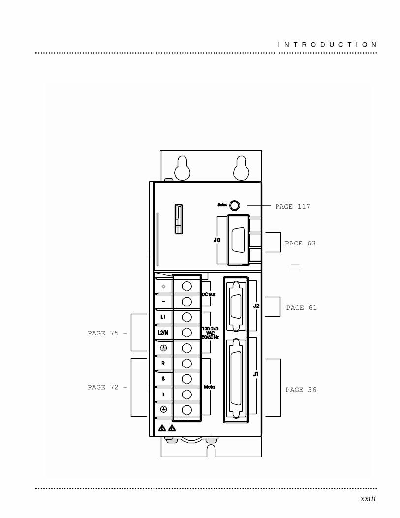
PAGE 117
PAGE 63
PAGE 61
PAGE 36
PAGE 75 -
PAGE 72 -

xxiv
I N T R O D U C T I O N
J2 - Encoder1234567891011121314151617181920
Encoder + 5V PWREncoder VCOM
Encoder + 5V PWREncoder VCOM
reservedreserved
Mtr. Encdr Input Chnl A+Mtr. Encdr Input Chnl A-Mtr. Encdr Input Chnl B+Mtr. Encdr Input Chnl B-Mtr. Encdr Input Chnl I+Mtr. Encdr Input Chnl I-
Hall AHall BHall C
Absolute Positionreservedreserved
Thermal Switch +Thermal Switch -
J3 - Serial Port123456789
RCV+RCVXMTXMT+COMreservedRCV-XMT-reserved
RS-485RS-232RS-232RS-485
RS-485RS-485
41424344454647484950
reservedSelectable Output 1Selectable Output 2
reservedreservedreservedreservedreserved
Brake Enable +Brake Enable -
J1 - Controller1234567891011121314151617181920
Encoder + 5VDC PWREncoder COM
Encoder + 5VDC PWREncoder COMExternal 12-24
External I/O COMMtr. Output Chnl A+Mtr. Output Chnl A-Mtr. Output Chnl B+Mtr. Output Chnl B-Mtr. Output Chnl I+Mtr. Output Chnl I-External I/O COMAuxiliary Chnl A+Auxiliary Chnl A-Auxiliary Chnl B+Auxiliary Chnl B-Auxiliary Chnl I+Auxiliary Chnl I-
Drive Enable2122232425262728293031323334353637383940
Fault ResetAnalog Cmnd+Analog Cmnd-Drive Ready+Drive Ready-
External 12-24I+ limit
Analog COM-I Limit
reservedAnalog Output 1
Selectable Input 1Selectable Input 2Selectable Input 3
reservedreservedreservedreservedreservedreserved
1_1
1Installing and Using the SSD Drive
Read the complete manual before attempting to install or operatethe drive. By reading the manual you will become familiar withpractices and procedures that allow you to operate the drive safelyand effectively.
Potential Hazards
The equipment described in this manual is intended for use inindustrial drive systems. This equipment can endanger life throughrotating machinery and high voltages, therefore it is essential thatguards for both electrical and mechanical parts are not removed.
Hazards which can be encountered in the use of this equipment are:• Electric Shock • Electric Fire • Mechanical • Stored Energy
These hazards must be controlled by suitable machine design, usingthe safety guidelines which follow. There are no chemical or ionizingradiation hazards.
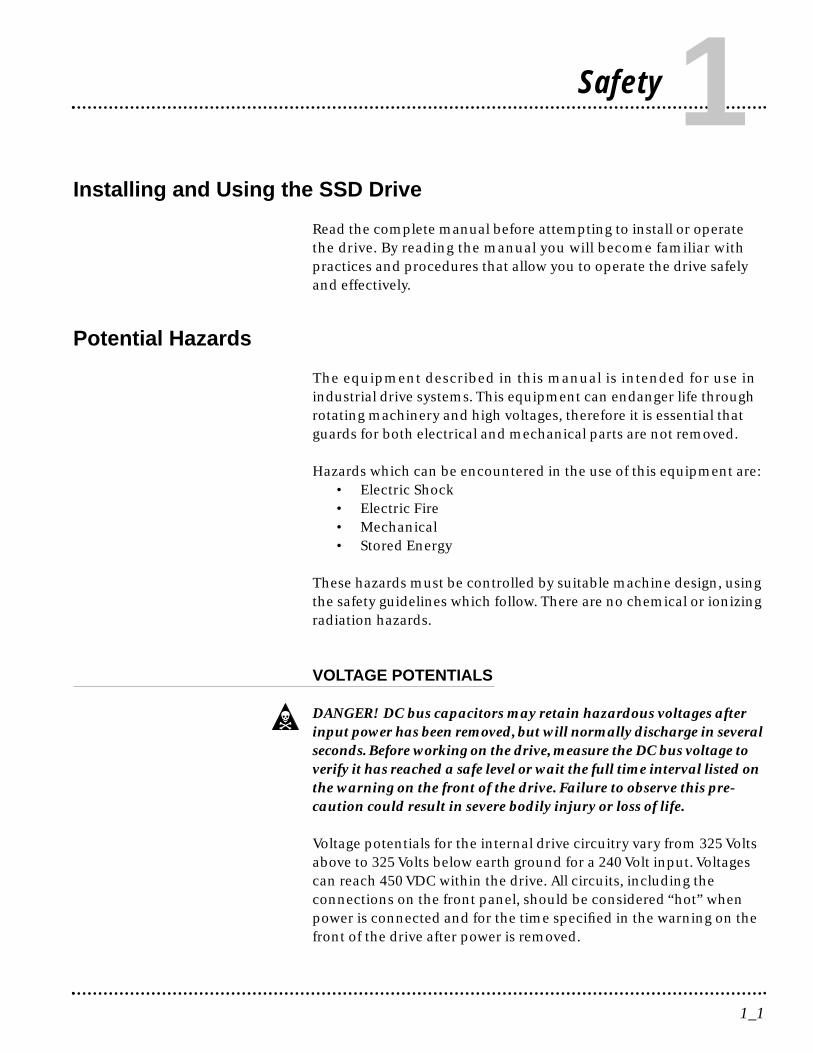
VOLTAGE POTENTIALS
DANGER! DC bus capacitors may retain hazardous voltages afterinput power has been removed, but will normally discharge in severalseconds. Before working on the drive, measure the DC bus voltage toverify it has reached a safe level or wait the full time interval listed onthe warning on the front of the drive. Failure to observe this pre-caution could result in severe bodily injury or loss of life.
Voltage potentials for the internal drive circuitry vary from 325 Voltsabove to 325 Volts below earth ground for a 240 Volt input. Voltagescan reach 450 VDC within the drive. All circuits, including theconnections on the front panel, should be considered “hot” whenpower is connected and for the time specified in the warning on thefront of the drive after power is removed.
Safety

1_2
Your Responsibilities
As the user or person installing this drive, you are responsible for de-termining the suitability of the product for the intended application.Tol-O-Matic is neither responsible nor liable for indirect or conse-quential damage resulting from the inappropriate use of this product.
A qualified person is someone who is familiar with all safety notesand established safety practices, with the installation, operation andmaintenance of this equipment and the hazards involved. For moredetailed definitions, refer to IEC 364.
It is recommended that anyone who operates or maintains electricalor mechanical equipment should have a basic knowledge of FirstAid. As a minimum, they should know where the First Aid equipmentis kept and the identity of the official First Aiders.
These safety notes do not represent a complete list of the stepsnecessary to ensure safe operation of the equipment. For furtherinformation, please contact the nearest distributor of Tol-O-Maticproducts.
Safety Guidelines
Electrical shock and fire hazards are avoided by using normalinstallation procedures for electrical power equipment in an industrialenvironment. Installation must be undertaken by suitably qualifiedpersonnel. Note that this amplifier must be installed in an industrialcabinet such that access is restricted to suitable qualified personnel.
Mechanical hazards are associated with potentially uncontrolledmovement of the motor shaft. If this imposes a risk in the machine,then appropriate precautions must be made to electrically discon-nect the motor from the drive when personnel have access to movingparts of the machine. Note also that the motor must be securelymounted at all times.
S A F E T Y
1_3
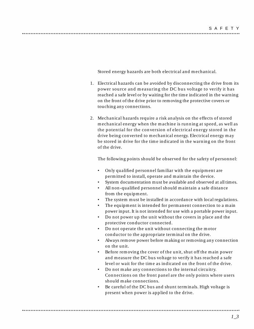
Stored energy hazards are both electrical and mechanical.
1. Electrical hazards can be avoided by disconnecting the drive from itspower source and measuring the DC bus voltage to verify it hasreached a safe level or by waiting for the time indicated in the warningon the front of the drive prior to removing the protective covers ortouching any connections.
2. Mechanical hazards require a risk analysis on the effects of storedmechanical energy when the machine is running at speed, as well asthe potential for the conversion of electrical energy stored in thedrive being converted to mechanical energy. Electrical energy maybe stored in drive for the time indicated in the warning on the frontof the drive.
The following points should be observed for the safety of personnel:
• Only qualified personnel familiar with the equipment arepermitted to install, operate and maintain the device.
• System documentation must be available and observed at all times.• All non-qualified personnel should maintain a safe distance
from the equipment.• The system must be installed in accordance with local regulations.• The equipment is intended for permanent connection to a main
power input. It is not intended for use with a portable power input. • Do not power up the unit without the covers in place and the
protective conductor connected. • Do not operate the unit without connecting the motor
conductor to the appropriate terminal on the drive. • Always remove power before making or removing any connection
on the unit. • Before removing the cover of the unit, shut off the main power
and measure the DC bus voltage to verify it has reached a safelevel or wait for the time as indicated on the front of the drive.
• Do not make any connections to the internal circuitry.Connections on the front panel are the only points where usersshould make connections.
• Be careful of the DC bus and shunt terminals. High voltage ispresent when power is applied to the drive.
S A F E T Y

S A F E T Y
1_4
• Never connect the DC- (negative) terminal to earth ground, thedrive requires a floating DC bus.
• Do not use the ENABLE input as a safety shutdown. Alwaysremove power to a drive before maintaining or repairing the unit.
• Motors without thermal protection devices require a validthermal time constant. Otherwise the motor overload protectionwill not function properly.
This chapter describes the steps which ensure that the drive willfunction as specified. The steps include:
• Unpacking the SSD drive • Inspecting the drive for shipping damage • Testing the basic functionality of the drive • Guidelines for storing the drive.
Unpacking the Drive
1. Remove the SSD drive from the shipping carton and remove allpacking materials from the unit. The materials and carton may beretained for storage or shipment of the drive.
2. Check all items against the packing list. A label located on the side ofthe unit identifies:
• model number • part number• serial number • manufacturing date code.
Inspection Procedure
To protect the investment and ensure applicable warranty rights,Tol-O-Matic recommends the following steps be performed uponreceipt of the unit:• Inspect the unit for any physical damage that may have been
sustained during shipment.• Perform the Inspections Test to verify the functionality of the unit.
If damage is detected, either concealed or obvious, contact thepurchasing agent to make a claim with the shipper. If degradedperformance is detected when testing the unit, contact the nearestdistributor of Tol-O-Matic products to obtain a Return MaterialAuthorization (RMA). Do this as soon as possible after receipt ofthe unit.
The Warranty section on page F-161 summarizes the period andconditions under which SSD drives are warranted against defects.
2_5
Unpacking, Inspecting & Storing 2
Testing the Unit
Drives are burned-in and individually tested before they leave thefactory. However, damage may occur during shipping. Perform theprocedures below to ensure the SSD drive is operational andundamaged.
Abbreviated directions for connecting the drive to a motor and a PCare provided. The test requires:
• Approximately 20 minutes to complete• A motor with appropriate power and encoder cables• A PC with the Tol-O-Motion SSD software package installed• An RS-232 communications cable• An external 24 VDC power supply • A single phase 100-240 VAC, 50/60 Hz power source. Standard
wall outlet power is suitable for verification testing of SSD drives. • A test cable constructed from two normally open switches,
several pieces of 1.5 mm2 (16 AWG) wire and a mating connector.Connectors are listed in Mating Connectors on page A-138. TheAppendix Options and Accessories on page A-137 lists the cables.
During the test, power is removed several times. Always measure theDC Bus voltage to verify the bus capacitors are fully discharged, orwait for the time indicated in the warning on the front of the drive.The bus capacitors must be fully discharged for the subsequentsteps to be valid.
If problems are encountered during this procedure, refer to Troubleshootingon page 11-121 of this manual, review other appropriate sections in thismanual, or call the local distributor of Tol-O-Matic products.
WARNING! Perform the initial power-up with the motor shaft dis-connected from a load and the shaft key removed. Improper wiringor undiscovered shipping damage could result in undesired motormotion. Be prepared to remove power if excessive motion occurs.
U N P A C K I N G , I N S P E C T I N G & S T O R I N G
2_6
Hardware setup
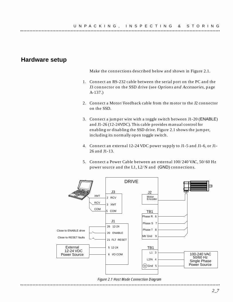
Make the connections described below and shown in Figure 2.1.
1. Connect an RS-232 cable between the serial port on the PC and theJ3 connector on the SSD drive (see Options and Accessories, pageA-137.)
2. Connect a Motor/Feedback cable from the motor to the J2 connectoron the SSD.
3. Connect a jumper wire with a toggle switch between J1-20 (ENABLE)and J1-26 (12-24VDC). This cable provides manual control forenabling or disabling the SSD drive. Figure 2.1 shows the jumper,including its normally open toggle switch.
4. Connect an external 12-24 VDC power supply to J1-5 and J1-6, or J1-26 and J1-13.
5. Connect a Power Cable between an external 100/240 VAC, 50/60 Hzpower source and the L1, L2/N and (GND) connections.
J3
DRIVE
J1
TB1
TB1
26 12-24
20 ENABLE
21 FLT RESET
2 RCV
3 XMT
5 COM
Phase R 6
Phase S 7
Phase T 8
Mtr Gnd 9
L1 3
L2/N 4
Gnd 5
100-240 VAC50/60 Hz
Single Phase
XMT
RCV
COM
Close to ENABLE drive
Close to RESET faults
Power Source
J2MotorEncoder
External12-24 VDC
Power Source
5 12-24
6 I/O COM
2_7
U N P A C K I N G , I N S P E C T I N G & S T O R I N G
Figure 2.1 Host Mode Connection Diagram

Drive Checkout Test
WARNING! Be prepared to disable the drive or remove input power ifexcessive motor motion occurs while performing the following steps.
This test sequentially verifies that:• Drive power wiring is correct and start-up logic is functioning.• The drive and motor are correctly wired• Drive serial communications are operational
Before beginning the Initial Power-up, please check the following:• All wiring and mounting to verify correct installation• Input voltages to ensure they do not exceed specifications for the
drive or motor.
INITIAL POWER-UP
1. Verify the AC power is within specifications at the terminal strip.
2. Switch the AC Power to ON and verify the Status LED is green.
3. Switch the power to OFF and wait until the DC Bus Voltage is below30 Volts.
4. Connect the motor windings to:• R (TB1-6)for the Phase R winding • S (TB1-7) for the Phase S winding • T (TB1-8) for the Phase T winding • for the Ground connection.
5. If a brake motor is being used for the test, connect the brake relay:• Refer to page 6-43
6. Switch AC Power ON again and verify the STATUS LED is green.
7. Switch the power OFF and wait until the DC Bus Voltage is below 30Volts.
U N P A C K I N G , I N S P E C T I N G & S T O R I N G
2_8
COMMUNICATIONS VERIFICATION
8. Start Tol-O-Motion SSD on the PC.
9. Close any windows that are open in Tol-O-Motion SSD.
10. Select PC setup from the Communications menu in Tol-O-MotionSSD.
11. Verify the communication port settings match those of the drive,then select OK. Factory default drive settings are:
• Baud Rate: 9600• Data Bits: 8• Parity: None• Stop Bits: 1• Serial Port: COM1
Assignment of communications ports on PCs varies between man-ufacturers. The COM port setting for the drive and PC must match.Refer to Troubleshooting on page 11-121 if communication problemsare encountered.
12. Switch AC power ON.
13. Select Read Drive Parameters from the Communications menu inTol-O-Motion SSD.
14. Select OK in the Drive Select dialog box. A dialog box indicating thatthe PC is reading drive parameters should appear.
If this dialog box does not appear, a message appears advising theuser to check the COM settings and the communication cable. Ifnecessary, refer to Troubleshooting on page 11-121 for instructionson how to perform these checks.
2_9
U N P A C K I N G , I N S P E C T I N G & S T O R I N G
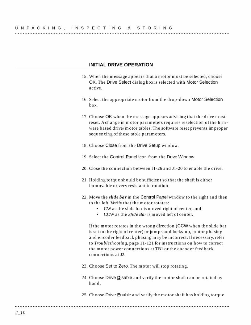
INITIAL DRIVE OPERATION
15. When the message appears that a motor must be selected, chooseOK. The Drive Select dialog box is selected with Motor Selectionactive.
16. Select the appropriate motor from the drop-down Motor Selectionbox.
17. Choose OK when the message appears advising that the drive mustreset. A change in motor parameters requires reselection of the firm-ware based drive/motor tables. The software reset prevents impropersequencing of these table parameters.
18. Choose Close from the Drive Setup window.
19. Select the Control Panel icon from the Drive Window.
20. Close the connection between J1-26 and J1-20 to enable the drive.
21. Holding torque should be sufficient so that the shaft is eitherimmovable or very resistant to rotation.
22. Move the slide bar in the Control Panel window to the right and thento the left. Verify that the motor rotates:
• CW as the slide bar is moved right of center, and • CCW as the Slide Bar is moved left of center.
If the motor rotates in the wrong direction (CCW when the slide baris set to the right of center) or jumps and locks-up, motor phasingand encoder feedback phasing may be incorrect. If necessary, referto Troubleshooting, page 11-121 for instructions on how to correctthe motor power connections at TB1 or the encoder feedbackconnections at J2.
23. Choose Set to Zero. The motor will stop rotating.
24. Choose Drive Disable and verify the motor shaft can be rotated byhand.
25. Choose Drive Enable and verify the motor shaft has holding torque
U N P A C K I N G , I N S P E C T I N G & S T O R I N G
2_10
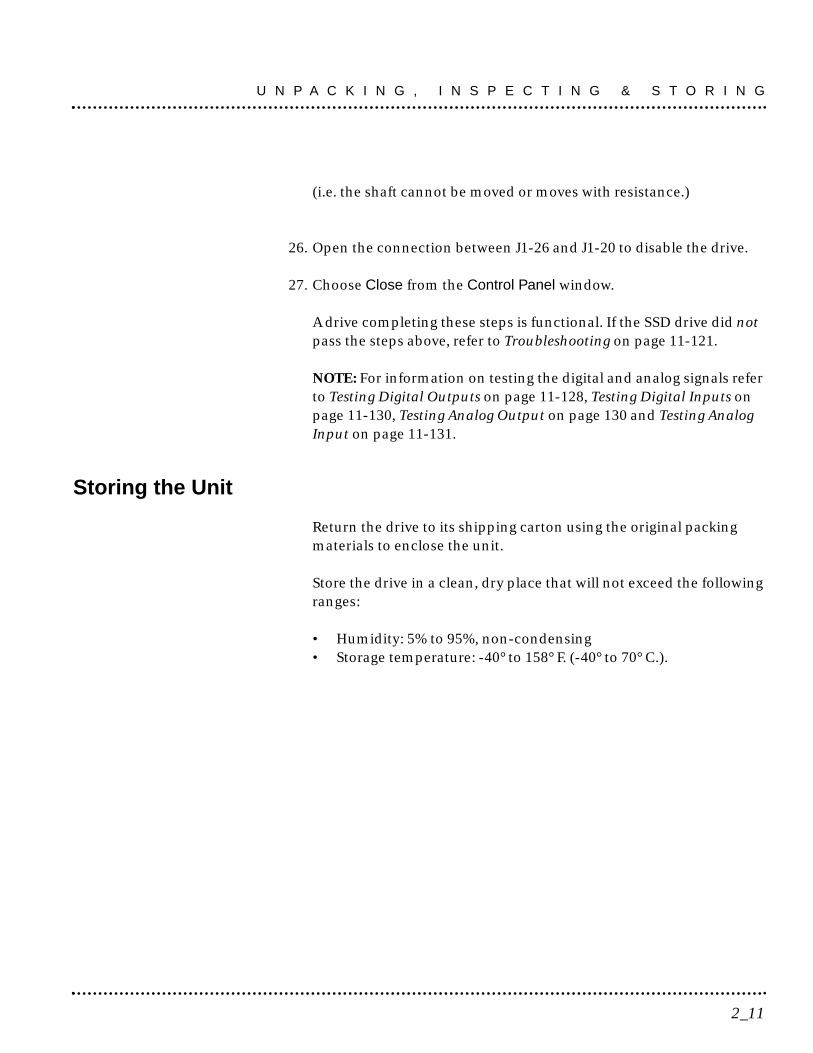
(i.e. the shaft cannot be moved or moves with resistance.)
26. Open the connection between J1-26 and J1-20 to disable the drive.
27. Choose Close from the Control Panel window.
A drive completing these steps is functional. If the SSD drive did notpass the steps above, refer to Troubleshooting on page 11-121.
NOTE: For information on testing the digital and analog signals referto Testing Digital Outputs on page 11-128, Testing Digital Inputs onpage 11-130, Testing Analog Output on page 130 and Testing AnalogInput on page 11-131.
Storing the Unit
Return the drive to its shipping carton using the original packingmaterials to enclose the unit.
Store the drive in a clean, dry place that will not exceed the followingranges:
• Humidity: 5% to 95%, non-condensing• Storage temperature: -40° to 158° F. (-40° to 70° C.).
2_11
U N P A C K I N G , I N S P E C T I N G & S T O R I N G
3_12
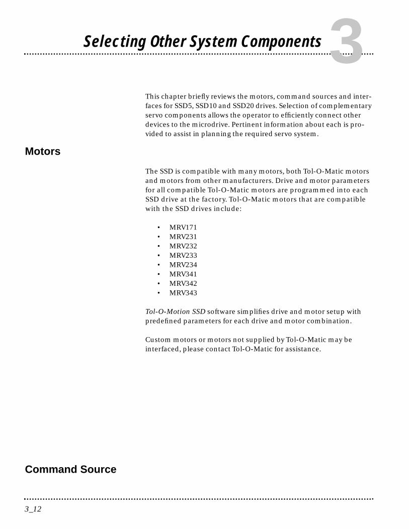
3This chapter briefly reviews the motors, command sources and inter-faces for SSD5, SSD10 and SSD20 drives. Selection of complementaryservo components allows the operator to efficiently connect otherdevices to the microdrive. Pertinent information about each is pro-vided to assist in planning the required servo system.
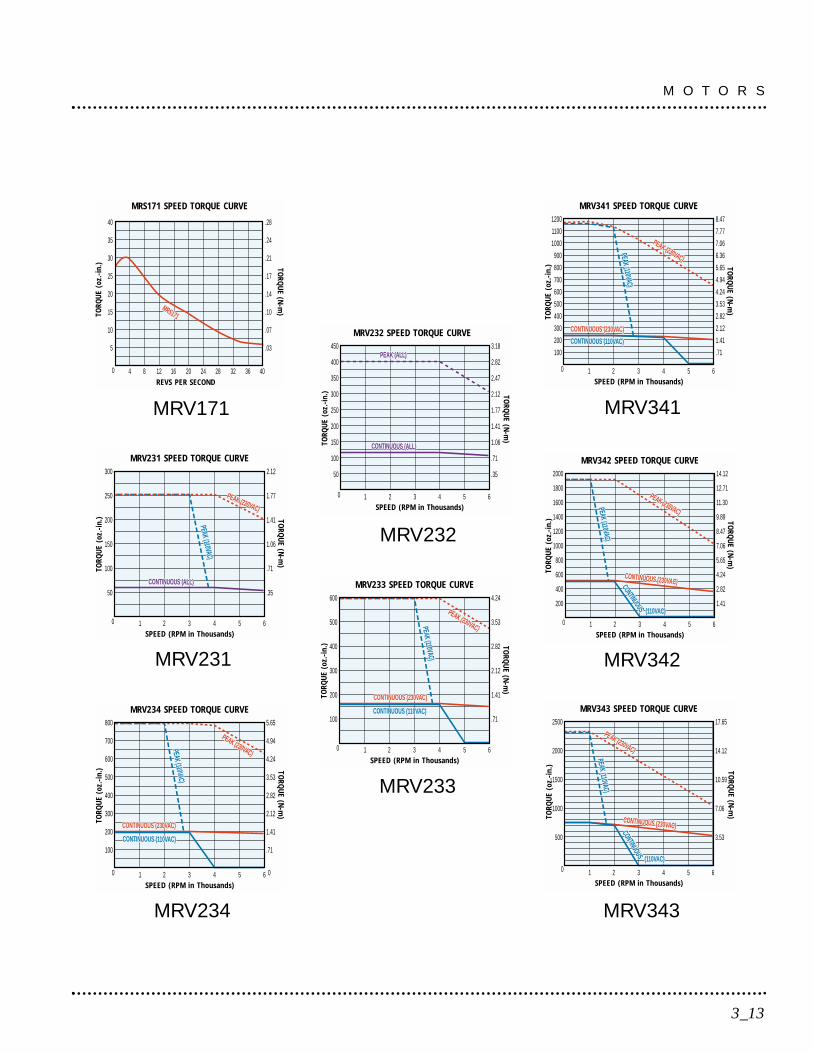
Motors
The SSD is compatible with many motors, both Tol-O-Matic motorsand motors from other manufacturers. Drive and motor parametersfor all compatible Tol-O-Matic motors are programmed into eachSSD drive at the factory. Tol-O-Matic motors that are compatiblewith the SSD drives include:
• MRV171• MRV231• MRV232• MRV233• MRV234• MRV341• MRV342• MRV343
Tol-O-Motion SSD software simplifies drive and motor setup withpredefined parameters for each drive and motor combination.
Custom motors or motors not supplied by Tol-O-Matic may beinterfaced, please contact Tol-O-Matic for assistance.
Command Source
Selecting Other System Components
3_13
M O T O R S
MRV341 SPEED TORQUE CURVE
SPEED (RPM in Thousands)
TORQ
UE
(oz.
-in.
) TORQ
UE (N
-m)
0
100
200
300
400
500
600
700
800
900
1000
1100
1200
.71
1.41
2.12
2.82
3.53
4.24
4.94
5.65
6.36
7.06
7.77
8.47
1 2 3 4 5 6
PEAK (230VAC)
CONTINUOUS (230VAC)
CONTINUOUS (230VAC)
PEAK (110VAC)
PEAK (230VAC)
CONTINUOUS (230VAC)
CONTINUOUS (110VAC)
PEAK (110VAC)
MRV343 SPEED TORQUE CURVE
SPEED (RPM in Thousands)
TORQ
UE
(oz.
-in.
) TORQ
UE (N
-m)
3.53
7.06
10.59
14.12
17.65
0
500
1000
1500
2000
2500
1 2 3 4 5 6
PEAK (230VAC)
CONTINUOUS (230VAC)CONTINUOUS (230VAC)
PEAK (110VAC)
PEAK (230VAC)
CONTINUOUS (230VAC)CONTINUOUS
(110VAC)
PEAK (110VAC)
MRV232 SPEED TORQUE CURVE
SPEED (RPM in Thousands)
TORQ
UE
(oz.
-in.
)
0
50
100
150
200
250
300
350
400
450
.35
.71
1.06
1.41
1.77
2.12
2.47
2.82
3.18
1 2 3 4 5 6
TORQ
UE (N
-m)
PEAK (ALL)
CONTINUOUS (ALL)
PEAK (ALL)
CONTINUOUS (ALL)
MRV233 SPEED TORQUE CURVE
SPEED (RPM in Thousands)
TORQ
UE
(oz.
-in.
) TORQ
UE (N
-m)
0
100
200
300
400
500
600
.71
1.41
2.12
2.82
3.53
4.24
1 2 3 4 5 6
PEAK (230VAC)
CONTINUOUS (230VAC)
CONTINUOUS (230VAC)
PEAK (110VAC)
PEAK (230VAC)
CONTINUOUS (230VAC)
CONTINUOUS (110VAC)
PEAK (110VAC)
MRV342 SPEED TORQUE CURVE
SPEED (RPM in Thousands)
TORQ
UE
(oz.
-in.
) TORQ
UE (N
-m)
1.41
2.82
4.24
5.65
7.06
8.47
9.89
11.30
12.71
14.12
0
200
400
600
800
1000
1200
1400
1600
1800
2000
1 2 3 4 5 6
PEAK (230VAC)
CONTINUOUS (230VAC)CONTINUOUS (230VAC)
PEAK (110VAC)
PEAK (230VAC)
CONTINUOUS (230VAC)CONTINUOUS (110VAC)
PEAK (110VAC)
MRV231 SPEED TORQUE CURVE
SPEED (RPM in Thousands)
TORQ
UE
(oz.
-in.
) TORQ
UE (N
-m)
0
50
100
150
200
250
300
.35
.71
1.06
1.41
1.77
2.12
1 2 3 4 5 6
PEAK (230VAC)
CONTINUOUS (ALL)
PEAK (110VAC)
PEAK (230VAC)
CONTINUOUS (ALL)
PEAK (110VAC)
MRV234 SPEED TORQUE CURVE
SPEED (RPM in Thousands)
TORQ
UE
(oz.
-in.
) TORQ
UE (N
-m)
0
.71
1.41
2.12
2.82
3.53
4.24
4.94
5.65
0
100
200
300
400
500
600
700
800
1 2 3 4 5 6
PEAK (230VAC)
CONTINUOUS (230VAC)
CONTINUOUS (230VAC)
PEAK (110VAC)
PEAK (230VAC)
CONTINUOUS (230VAC)
CONTINUOUS (110VAC)
PEAK (110VAC)
MRV231
MRV234
MRV232
MRV341
MRV343
MRS171 SPEED TORQUE CURVE
REVS PER SECOND
TORQ
UE
(oz.
-in.
) TORQ
UE (N
-m)
0
5
10
15
20
25
30
35
40
.03
.07
.10
.14
.17
.21
.24
.28
4 8 12 16 20 24 28 32 36 40
MRS231MRS171
MRV171
MRV233
MRV342
In the analog mode of operation, the SSD drive requires a variable±10 Volt DC external analog signal capable of driving the servoregulator’s command input at an input impedance of 13.3 kOhms.Choose a source such as a PLC (programmable logic controller), theDAC (digital-to-analog converter) of a computer, or a motioncontroller that meets this requirement.
Differential or single-ended line drivers may supply the signals for theencoder inputs, step and direction inputs, and step up/down inputs.The differential signal must be capable of supplying at least 5 mA with2.0 Volts across the + and - inputs. A differential signal source providesthe best noise margin of all the interface circuit options. Single-endedsignals from TTL drivers must be capable of sourcing or sinking 5 mA.
In the preset mode, the controlling device should be capable ofsourcing 4.5 mA into the digital inputs.
Serial Communications Interface
SSD drives are configured and controlled via a serial communicationlink. The serial port allows the SSD to interface with other user-supplied equipment such as:
• Host computers• PLCs• PCs• Motion controllers.
The serial communication interface for the SSD supports:
• RS-232 and the four wire RS-485 communications standards• NRZ (non-return to zero) asynchronous serial format• Baud rates: 1200, 2400, 4800, 9600 and 19200• Parity generation and checking: Even, Odd or None.
Connection of communication cables between the drive and user-supplied equipment is described in the following sections:
• One SSD drive - Single Axis RS-232 setup on page 6-66.• Multiple SSD drives - Multiple Axes Four-Wire RS-485 on page 6-67.
S E L E C T I N G O T H E R S Y S T E M C O M P O N E N T S
3_14
I/O Interface
ANALOG INPUT
One analog input channel is accessible to the user. The analog inputlimits the peak current available from the drive.
LIMIT (current limit). The analog signal must be within 0-10 Voltrange and single-ended.
If this signal is not provided, the peak current of the drive may be setin software through the Drive Parameter window.
ANALOG OUTPUT
One analog output channel may be defined by the user throughsoftware:
ANALOG is a ±10 Volt signal. The allowable current draw of the loadis ±2 mA
This analog output is designed for monitoring purposes only. Tol-O-Matic recommends this signal not be used for control purposes dueto the relatively high ripple voltage (1%).
3_15
S E L E C T I N G O T H E R S Y S T E M C O M P O N E N T S
DIGITAL INPUTS
Control InputsTwo, optically isolated, single ended, active high, dedicated controlinputs provide controller ENABLE, and FAULT RESETfunctions. These inputs operate with switch closure or sourcing typetransistor outputs.
The current rating of each input is 10 mA nominal.
Selectable InputsThree, optically isolated, single ended, active high inputssupport logic type interfaces. The input circuits operate with switchclosure or sourcing type transistor circuits. Selectable inputs are:
• Drive Mode Select• Integrator Inhibit• Follower Enable• Forward Enable• Reverse Enable• Preset Selects (3 presets provide up to 8 digital preset
combinations)• Analog Override.
The current rating of each input is 10 mA nominal.
DIGITAL OUTPUTS
Control OutputsTwo normally open relays are dedicated control outputs to thefollowing signals:
• BRAKE/DRIVE ENABLED• DRIVE READY
The current ratings of each relay is 1 Amp at 30 VDC.
If using a motor with the 90VAC brake option, a user-provided relaymay be driven by these outputs up to the specified levels. Refer toI/O Configuration in the on-line Tol-O-Motion SSD help for
S E L E C T I N G O T H E R S Y S T E M C O M P O N E N T S
3_16
additional information about the software parameters.
Selectable OutputsTwo, optically isolated, single ended, active high, currentsourcing, discrete output channels provide logic outputs undersoftware control. Selectable outputs are:
• In Position• Position Window• Zero Speed• Speed Window• Peak Current Limit• At Speed• Drive Enabled• Bus Charged
Each selectable output channel is capable of sourcing 50 mAmaximum and is optically isolated and short circuit protected.
AUXILIARY ENCODER INTERFACE
The external encoder I/O port permits quadrature-type encodersignals for applications, such as electronic gearing.
Encoder InputsSoftware automatically selects the appropriate input based on thecommand source:
• Master Encoder• Step/Direction• Step Up/Step Down.
Encoder OutputThe resolution of the encoder output channel is under softwarecontrol. The motor encoder signal is divided by 1, 2, 4 or 8 to providean output from a differential line driver measured in PPR (pulses perrevolution). The maximum encoder frequency output is 1 MHz (4MHz quadrature).
3_17
S E L E C T I N G O T H E R S Y S T E M C O M P O N E N T S

European Union Requirements
SSD drives conform to the following European Union Directives:
• Low Voltage Directive (72/23/EEC, 93/68/EEC)• Electromagnetic Compatibility Directive (89/336/EEC,
92/31/EEC, 93/68/EEC)
Compliance with the EEC Directives is contingent on:
A. Installation of AC line filters between the power source and thedrive.
B. The use of certified cables.
S E L E C T I N G O T H E R S Y S T E M C O M P O N E N T S
3_18

This chapter provides information about:
• minimum PC hardware and software necessary to run Tol-O-Motion SSD;
• step-by-step instructions on how to load Tol-O-Motion SSD;• how to start and quit Tol-O-Motion SSD and introduces the
Drive Window, the main command window for Tol-O-Motion SSD;• how to access on-line help.
Instructions for using the features available in Tol-O-Motion SSDare detailed in on-line help. To access the Help menu, press the F1key.
Hardware and Software Requirements
The minimum PC configuration required to run the software includes:
• A DOS-based computer with a minimum 286 microprocessor • A hard disk with 2.0 MB of free disk space • 31/2 inch, 1.44MB floppy disk drive • 2 MB of RAM • A Video Graphics Array (VGA) monitor • Microsoft Windows version 3.1, 95, or NT• Mouse (recommended)
Windows must be installed on the PC. If Windows is not alreadyinstalled, refer to the appropriate Microsoft manual to installWindows on the computer.
Installation
To install Tol-O-Motion SSD software on a hard drive:1. Make a backup copy of the Tol-O-Motion SSD disk in one of two
ways:
• Copy the Tol-O-Motion SSD disk using the Disk menu in theWindows File Manager.
• If the computer has only one floppy disk drive: at the DOScommand line prompt, type diskcopy a: b: (be sure to includespaces), then press ENTER. The software will prompt the userwhen to insert the source disk (Tol-O-Motion SSD) and whento insert the target disk (blank).
4_19
Installing Tol-O-Motion SSD Software4

2. If Windows is not running, type win at the DOS prompt (C:>). If Windows is already running, close any open applications.
3. Insert the Tol-O-Motion SSD disk into a 1.44MB floppy disk drive,(typically drive A:), then close the drive door.
4. Choose Run, from the File menu in Windows Program Manager.
5. Type a:setup and then press ENTER. A message box will appearindicating that Setup is initializing. The message box may be presentfor up to 40 seconds, depending on the speed of the PC.
6. A dialog box prompts the user to confirm whether or not Tol-O-Motion SSD should be installed on the hard drive (C: drive) of thePC.
To install Tol-O-Motion SSD:Choose Continue, or press ENTER, and continue with the next step.
To stop the installation:Choose Exit. The program returns to Windows.
7. Setup then asks where Tol-O-Motion SSD should be installed.
To accept the path Setup proposes in the Path: box(c:\tolomotn\...):Choose Continue.
To choose another directory:Type a new path in the Path: box, then choose Continue. NOTE:There is no confirmation of the entry so be sure to type carefully.
To return to the initial Setup window:Choose Back.
To stop the installation:Choose Exit. The program returns to Windows.
To obtain on-line help with the installation:Choose Help.
I N S T A L L I N G T O L - O - M O T I O N S O F T W A R E
4_20

8. A status bar informs the user of installation progress. When Setup iscomplete, choose OK or press ENTER to return to Windows.
Starting and Quitting Tol-O-Motion SSD
Setup automatically creates the Tol-O-Motion SSD program groupand then returns the user to Windows. The Tol-O-Motion SSDprogram group provides access to the Tol-O-Motion SSD applicationicon from the C:> prompt or Windows.
To access Tol-O-Motion SSD from the C:> PromptType win c:\tolomotn\tolomotn.exe. NOTE: This step assumes Tol-O-Motion SSD was loaded into the c:\tolomotn directory duringsetup.
The Tol-O-Motion SSD start-up screen will open.
To access Tol-O-Motion SSD from Windows1. Choose the Tol-O-Motion SSD program group from the Program
Manager in Windows.
TIP: If the Tol-O-Motion SSD window is not active, hold downCTRL and press TAB (CTRL+TAB) until the Tol-O-Motion SSDtitle bar and icon are highlighted, or select Tol-O-Motion SSDfrom the list in the Window menu.
2. Choose the Tol-O-Motion SSD icon from the Tol-O-Motion SSDprogram group. The Tol-O-Motion SSD start-up screen will open.
4_21
I N S T A L L I N G T O L - O - M O T I O N S O F T W A R E
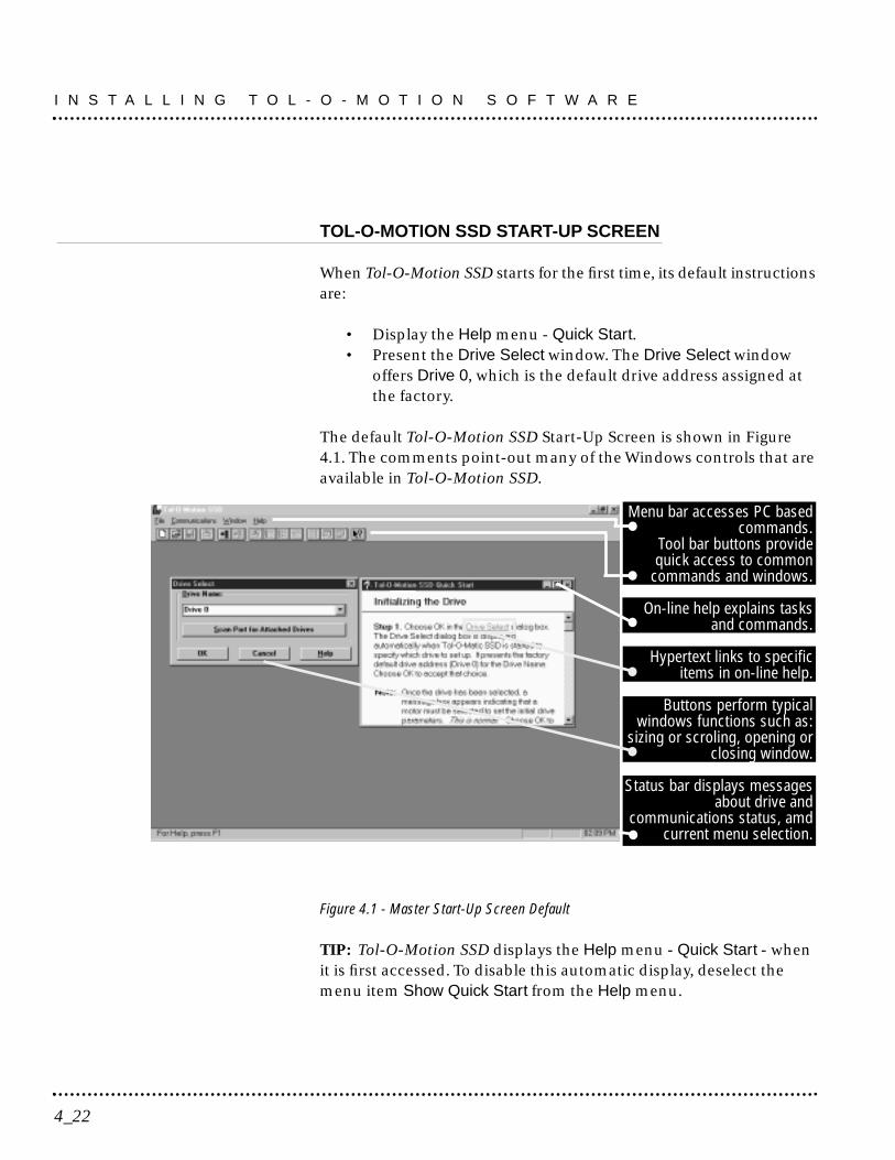
TOL-O-MOTION SSD START-UP SCREEN
When Tol-O-Motion SSD starts for the first time, its default instructionsare:
• Display the Help menu - Quick Start. • Present the Drive Select window. The Drive Select window
offers Drive 0, which is the default drive address assigned atthe factory.
The default Tol-O-Motion SSD Start-Up Screen is shown in Figure4.1. The comments point-out many of the Windows controls that areavailable in Tol-O-Motion SSD.
Figure 4.1 - Master Start-Up Screen Default
TIP: Tol-O-Motion SSD displays the Help menu - Quick Start - whenit is first accessed. To disable this automatic display, deselect themenu item Show Quick Start from the Help menu.
I N S T A L L I N G T O L - O - M O T I O N S O F T W A R E
4_22
Menu bar accesses PC basedcommands.
Tool bar buttons providequick access to common
commands and windows.
On-line help explains tasksand commands.
Hypertext links to specificitems in on-line help.
Buttons perform typicalwindows functions such as:
sizing or scroling, opening orclosing window.
Status bar displays messagesabout drive and
communications status, amdcurrent menu selection.

THE README FILE
A file titled README, may be included in the Tol-O-Motion SSDdirectory. This file contains installation instructions, changenotes from previous revisions, and information that becameavailable after this manual was printed. After Tol-O-Motion SSD isinstalled, it is possible to access this file by:
1. choosing the Read Me icon (shown at left) in the Tol-O-MotionSSD window; or
2. using Microsoft Write or an equivalent application program toview the file "readme.wri" in the directory path where Tol-O-Motion SSD is installed.
MISCELLANEOUS FILES
Firmware FilesFour hexadecimal files are supplied in the Miscellaneous directoryon the Tol-O-Motion SSD diskette. The current revision level of drivefirmware is displayed in the Drive Information window of Tol-O-Motion SSD.
The hexadecimal files and their functions are:
• Firmware - Main Operating firmware for the drive• Boot Block - Drive Initialization firmware for the drive• Motor Table Block - Motor Parameter firmware for the drive.
4_23
I N S T A L L I N G T O L - O - M O T I O N S O F T W A R E

I N S T A L L I N G T O L - O - M O T I O N S O F T W A R E
4_24

Mechanical Installation Requirements
1. Mount the unit in an enclosure providing protection to IP54 (protectedagainst dust and splashing water), or IP65 (dust free and protectedagainst water jets) if the work environment is poor. Many NEMA(National Electrical Manufacturers Association) Type 4 cabinetsprovide this level of protection. Minimum cabinet requirements are:
• Depth: 243.8 cm (9.6 inches).• Adequate sizing and/or ventilation to dissipate the heat generated
by the SSD drives. Refer to Power Dissipation on page E-159 forthe amount of heat generated by SSD drives and enclosure sizingequations.
2. Minimum unobstructed surrounding space for cooling air intake(and fan exhaust from the SSD20:)
• Above: 50.8 cm (2 inches)• Below: 50.8 cm (2 inches)• Sides: 1.25 cm (0.5 inches)• Front: 76.2 cm (3.0 inches) for cable clearance.
Caution! If the cabinet is ventilated, use filtered or conditioned air toprevent the accumulation of dust and dirt on electronic components.The air should be free of oil, corrosives, or electrically conductivecontaminates.
3. Position the drive in a vertical position on a flat, solid surface thatmeets the following weight, vibration and shock, altitude andhumidity, airflow clearance, and temperature requirements.
Unit weights are:• SSD5: 1.7 Kg (3.7 Lbs)• SSD10: 2.05 Kg (4.5 Lbs)• SSD20: 2.0 Kg (4.4 Lbs)
!
5_25
Installation 5
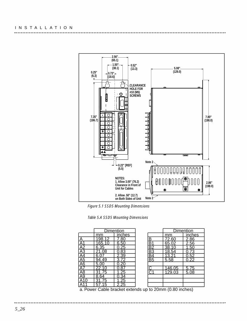
Figure 5.1 SSD5 Mounting Dimensions
Table 5.A SSD5 Mounting Dimensions
Dimention
BB1B2B3B4B5
CC1
mm72.6065.0238.1018.5413.215.58
146.05129.03
inches2.862.561.500.730.520.22
5.755.08
Dimention
AA1A2A3A4A5A6A7A8A9A10A11a. Power Cable bracket extends up to 20mm (0.80 inches)
mm198.12165.106.3521.086.0794.495.0022.1031.758.6431.7557.15
inches7.806.500.250.832.393.720.200.871.250.341.252.25
L1
L2/N
R
S
T
Motor
50/60 HzVAC
100-240
DC Bus
Status
J5
J2
J1
CLEARANCEHOLE FOR#10 (M5)SCREWS
0.52"(13.3)
2.56"(65.1)1.50"(38.1)
0.73"(18.6)
0.25"(6.3)
7.35"(186.7)
0.22" [REF](5.5)
5.08"(129.0)
7.80"(198.0)
Note 2
Note 2
2.86"(198.0)
NOTES:1. Allow 3.00" (76.2) Clearance in Front of Unit for Cables
2. Allow .50" (12.7) on Both Sides of Unit
I N S T A L L A T I O N
5_26
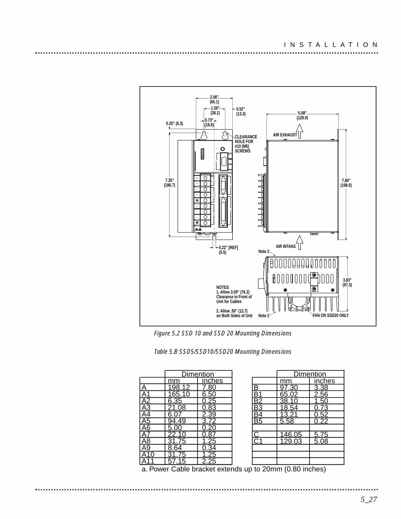
Figure 5.2 SSD 10 and SSD 20 Mounting Dimensions
Table 5.B SSD5/SSD10/SSD20 Mounting Dimensions
Dimention
BB1B2B3B4B5
CC1
mm97.3065.0238.1018.5413.215.58
146.05129.03
inches3.382.561.500.730.520.22
5.755.08
Dimention
AA1A2A3A4A5A6A7A8A9A10A11a. Power Cable bracket extends up to 20mm (0.80 inches)
mm198.12165.106.3521.086.0794.495.0022.1031.758.6431.7557.15
inches7.806.500.250.832.393.720.200.871.250.341.252.25
J5
Status
J2
50/60 HzVAC
100-240
DC Bus
L1
L2/N
J1
Motor
R
S
T
Note 2
Note 2
CLEARANCEHOLE FOR#10 (M5)SCREWS
0.52"(13.3)
2.56"(65.1)1.50"(38.1)
0.73"(18.6)0.25" (6.3)
7.35"(186.7)
0.22" [REF](5.5)
3.83"(97.3)
FAN ON SSD20 ONLY
5.08"(129.0)
7.80"(198.0)
AIR INTAKE
AIR EXHAUST
NOTES:1. Allow 3.00" (76.2) Clearance in Front of Unit for Cables
2. Allow .50" (12.7) on Both Sides of Unit
5_27
I N S T A L L A T I O N
Vibration and shock, altitude and humidity limits are:
• Vibration: 2g at 10 to 2000 Hz• Shock: 15g 11 msec half sine• Altitude: 1500 meters (5000 feet), Derate power performance
3% for ea. 300 m above 1500 m (1000 ft above 5000 ft).• Humidity: 5% to 95% non-condensing
Ambient operating temperature range and airflow clearances are:
• 0° to 55° C. (32° to 131° F.).• 50.8 mm (2 inches) above and below unit for airflow.
4. Bolt the unit to the cabinet using the mounting slots in the drive.Mounting dimensions are shown in Figure 5.2. The recommendedsize of mounting hardware is:
• M5 Metric (1/4-20 equivalent), or• #10 MS bolts.
Interface Connections
Input/Output and power cables connect to the front panel of a SSDdrive, no internal connections are necessary.
DANGER! The user is responsible for conforming with all applic-able local, national and international codes.Wiring practices,grounding, disconnects and overcurrent protection are of particu-lar importance. Failure to observe this precaution could result insevere bodily injury or loss of life.
I/O Connections are fully described in the following sections:
• J1 - Controller on page 6-36 defines the controller connections.• J2 - Encoder on page 6-61 defines the motor encoder connections.• J3 - Serial Port on page 6-63 defines the RS-232/RS-485 serial
port connections.
Power Connections are fully described in the following sections:
• Power Connections on page 7-71. defines the power connections.
I N S T A L L A T I O N
5_28

Specific operational setups are depicted in Figures 8.1 throughFigure 8.5 (pages 8-78 through 8-99). These figures cover velocityand torque mode controls for:
• Analog Controllers,• Preset Controllers,• Position Followers using a Master Encoder,• Position Followers using a Step/Direction signal, or• Position Followers using Step Up/Down signals.
Wiring
Wiring sizes and practices, as well as grounding and shielding tech-niques are described in the sections listed below. Refer to PowerConnections on page 7-71.
The descriptions represent common wiring practices and shouldprove satisfactory in the majority of applications.
Note: Cables, listed in Options and Accessories on page A-137, arenot rated for continuous flexing.
Minimum wire gages for power cables are listed in:
• Motor Power Contact and Wire Size Recommendations on page 7-76,• AC Input Power Sizing Requirements on page 7-76.
Electromagnetic Compatibility
GENERAL GUIDELINES
Refer to the appendix Electromagnetic Compatibility Guidelines forMachine Design on page C-141 for an in-depth discussion of electro-magnetic compatibility (EMC) and electromagnetic interference (EMI).
5_29
I N S T A L L A T I O N
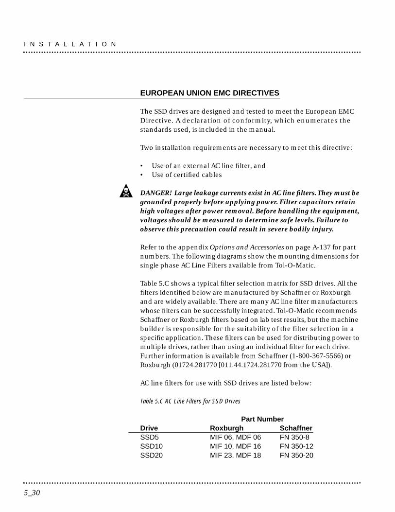
EUROPEAN UNION EMC DIRECTIVES
The SSD drives are designed and tested to meet the European EMCDirective. A declaration of conformity, which enumerates thestandards used, is included in the manual.
Two installation requirements are necessary to meet this directive:
• Use of an external AC line filter, and• Use of certified cables
DANGER! Large leakage currents exist in AC line filters.They must begrounded properly before applying power. Filter capacitors retainhigh voltages after power removal. Before handling the equipment,voltages should be measured to determine safe levels. Failure toobserve this precaution could result in severe bodily injury.
Refer to the appendix Options and Accessories on page A-137 for partnumbers. The following diagrams show the mounting dimensions forsingle phase AC Line Filters available from Tol-O-Matic.
Table 5.C shows a typical filter selection matrix for SSD drives. All thefilters identified below are manufactured by Schaffner or Roxburghand are widely available. There are many AC line filter manufacturerswhose filters can be successfully integrated. Tol-O-Matic recommendsSchaffner or Roxburgh filters based on lab test results, but the machinebuilder is responsible for the suitability of the filter selection in aspecific application. These filters can be used for distributing power tomultiple drives, rather than using an individual filter for each drive.Further information is available from Schaffner (1-800-367-5566) orRoxburgh (01724.281770 [011.44.1724.281770 from the USA]).
AC line filters for use with SSD drives are listed below:
Table 5.C AC Line Filters for SSD Drives
Part NumberDrive Roxburgh SchaffnerSSD5 MIF 06, MDF 06 FN 350-8SSD10 MIF 10, MDF 16 FN 350-12SSD20 MIF 23, MDF 18 FN 350-20
I N S T A L L A T I O N
5_30

Basic guidelines for reducing electrical noise and increasingelectromagnetic compatibility (EMC) are listed in ElectromagneticCompatibility Guidelines for Machine Design on page C-141.
5_31
I N S T A L L A T I O N

I N S T A L L A T I O N
5_32
This chapter provides information about:• Interface signals available on the SSD drive
- J1 - The Controller interface for commanding and reporting motion- J2 - The Encoder interface for reporting movement by the motor- J3 - The Serial interface for communicating with the drive.
• Commonly encountered interface cabling methods• Optional signal extension kits and standard cables.
6_35
Interfaces 6
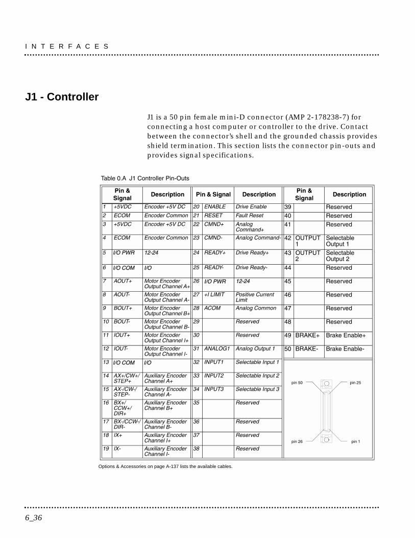
J1 - Controller
J1 is a 50 pin female mini-D connector (AMP 2-178238-7) forconnecting a host computer or controller to the drive. Contactbetween the connector’s shell and the grounded chassis providesshield termination. This section lists the connector pin-outs andprovides signal specifications.
Options & Accessories on page A-137 lists the available cables.
I N T E R F A C E S
6_36
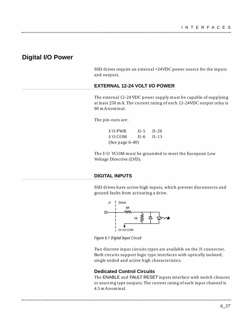
Digital I/O Power
SSD drives require an external +24VDC power source for the inputsand outputs.
EXTERNAL 12-24 VOLT I/O POWER
The external 12-24 VDC power supply must be capable of supplyingat least 250 mA. The current rating of each 12-24VDC output relay is90 mA nominal.
The pin-outs are:
I/O PWR J1-5 J1-26I/O COM J1-6 J1-13(See page 6-40)
The I/O VCOM must be grounded to meet the European LowVoltage Directive (LVD).
DIGITAL INPUTS
SSD drives have active high inputs, which prevent disconnects andground faults from activating a drive.
Figure 6.1 Digital Input Circuit
Two discrete input circuits types are available on the J1 connector.Both circuits support logic type interfaces with optically isolated,single ended and active high characteristics.
Dedicated Control CircuitsThe ENABLE and FAULT RESET inputs interface with switch closuresor sourcing type outputs. The current rating of each input channel is4.5 mA nominal.
6_37
I N T E R F A C E S

Selectable Circuits
INPUT 1, INPUT 2 and INPUT 3 operate with switch closures orsourcing type circuitry. The current rating of each input channel is4.5 mA nominal. Selectable inputs are:
Drive Mode Select Reverse Enable Analog OverrideIntegrator Inhibit Preset Select AFollower Enable Preset Select BForward Enable Preset Select C
Refer to the I/O Configuration section of the on-line Tol-O-MotionSSD Help for information on choosing the input type for eachchannel. Refer to the Preset Control Application example fordetailed use of the presets.
Table 6.B General and Dedicated Inputs
Inputs 1, 2 and 3 each may be software configured as Preset Select A, B or C.
J1-20
J1-21
J1-32
J1-33
J1-34
Enables and disables the drive. Motor torque cannot be applied
unless the ENABLE input is active.
Resets the drive after a fault. The controller is enabled ( if the
ENABLE switch is active) after the FAULT RESET is applied. If the
drive is not faulted when the RESET is made, the servo controller
ignores the RESET signal. The reset occurs on the transit.
General purpose input selectable to one of several drive functions.
Refer to Tol-O-Motion on-line Help and the table below
for I/O configuration.
General purpose input selectable to one of several drive functions.
Refer to Tol-O-Motion on-line Help and the table below
for I/O configuration.
General purpose input selectable to one of several drive functions.
Refer to Tol-O-Motion on-line Help and the table below
for I/O configuration.
PIN NUMBER FUNCTION/DESCRIPTION
ENABLE
FAULT RESET
INPUT 1
INPUT 2
INPUT 3
DIGITAL INPUT
I N T E R F A C E S
6_38
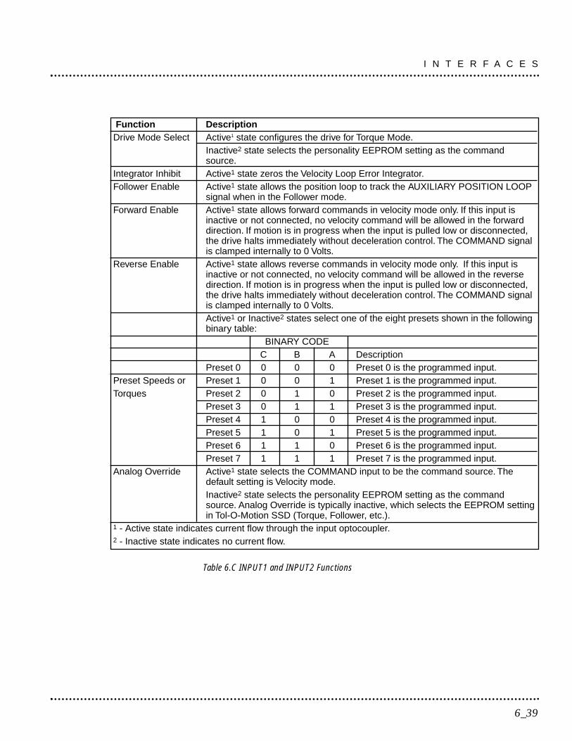
Table 6.C INPUT1 and INPUT2 Functions
6_39
I N T E R F A C E S
Function DescriptionDrive Mode Select Active1 state configures the drive for Torque Mode.
Inactive2 state selects the personality EEPROM setting as the commandsource.
Integrator Inhibit Active1 state zeros the Velocity Loop Error Integrator.Follower Enable Active1 state allows the position loop to track the AUXILIARY POSITION LOOP
signal when in the Follower mode.Forward Enable Active1 state allows forward commands in velocity mode only. If this input is
inactive or not connected, no velocity command will be allowed in the forwarddirection. If motion is in progress when the input is pulled low or disconnected,the drive halts immediately without deceleration control. The COMMAND signalis clamped internally to 0 Volts.
Reverse Enable Active1 state allows reverse commands in velocity mode only. If this input isinactive or not connected, no velocity command will be allowed in the reversedirection. If motion is in progress when the input is pulled low or disconnected,the drive halts immediately without deceleration control. The COMMAND signalis clamped internally to 0 Volts.Active1 or Inactive2 states select one of the eight presets shown in the followingbinary table:
BINARY CODEC B A Description
Preset 0 0 0 0 Preset 0 is the programmed input.Preset Speeds or Preset 1 0 0 1 Preset 1 is the programmed input.Torques Preset 2 0 1 0 Preset 2 is the programmed input.
Preset 3 0 1 1 Preset 3 is the programmed input.Preset 4 1 0 0 Preset 4 is the programmed input.Preset 5 1 0 1 Preset 5 is the programmed input.Preset 6 1 1 0 Preset 6 is the programmed input.Preset 7 1 1 1 Preset 7 is the programmed input.
Analog Override Active1 state selects the COMMAND input to be the command source. Thedefault setting is Velocity mode.Inactive2 state selects the personality EEPROM setting as the commandsource. Analog Override is typically inactive, which selects the EEPROM settingin Tol-O-Motion SSD (Torque, Follower, etc.).
1 - Active state indicates current flow through the input optocoupler.2 - Inactive state indicates no current flow.
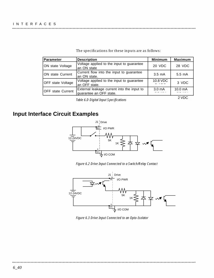
The specifications for these inputs are as follows:
Table 6.D Digital Input Specifications
Input Interface Circuit Examples
Figure 6.2 Drive Input Connected to a Switch/Relay Contact
Figure 6.3 Drive Input Connected to an Opto-Isolator
1K5K
I/O PWR265
DriveJ1
I/O COM
12-24VDC
136
1K5K
DriveJ1
I/O PWR
I/O COM
12-24VDC
265
136
Parameter Description Minimum Maximum
ON state VoltageVoltage applied to the input to guaranteean ON state
20 VDC 28 VDC
ON state CurrentCurrent flow into the input to guaranteean ON state.
3.5 mA 5.5 mA
OFF state VoltageVoltage applied to the input to guaranteean OFF state.
-1 VDC 3 VDC
OFF state CurrentExternal leakage current into the input toguarantee an OFF state.
-0.5 mA 0.5 mA
I N T E R F A C E S
6_40
10.8 VDC
3.0 mA 10.0 mA
2 VDC
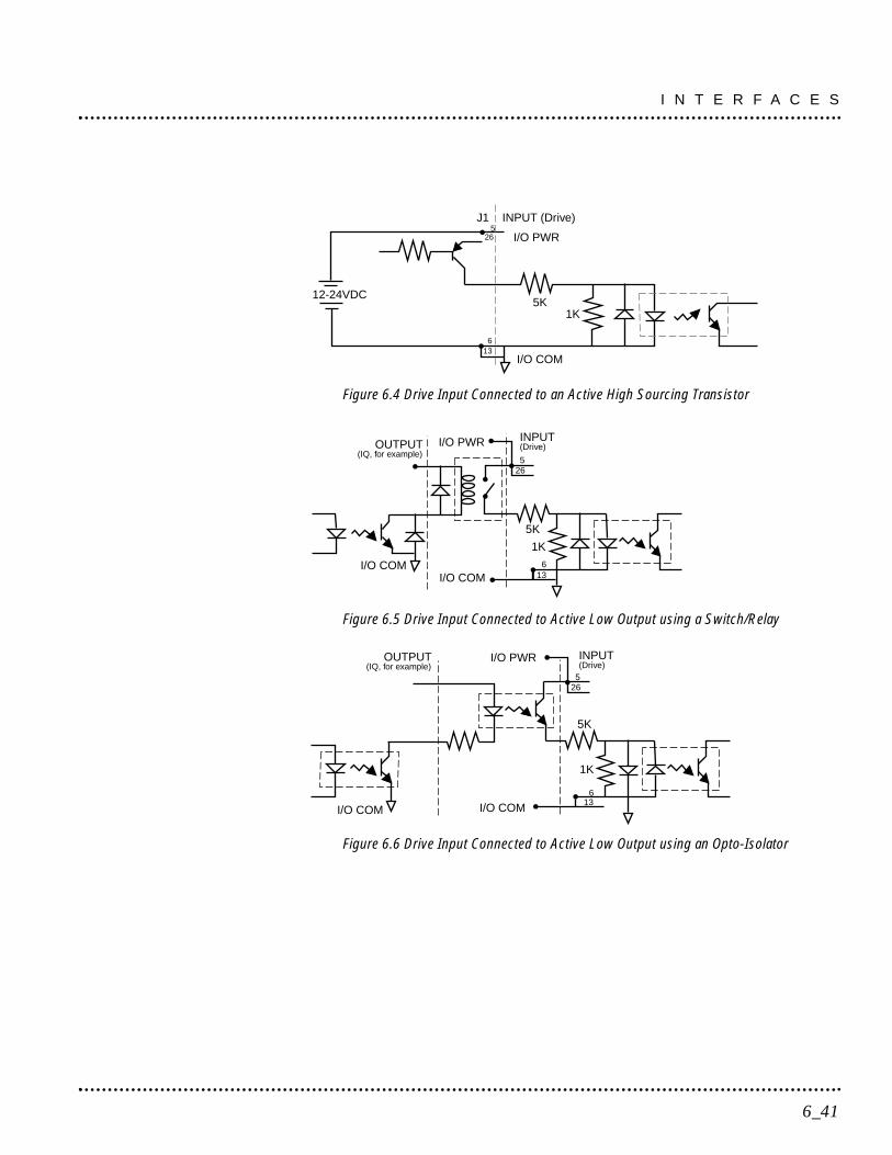
Figure 6.4 Drive Input Connected to an Active High Sourcing Transistor
Figure 6.5 Drive Input Connected to Active Low Output using a Switch/Relay
Figure 6.6 Drive Input Connected to Active Low Output using an Opto-Isolator
(Drive)OUTPUT
(IQ, for example)INPUT
5K
1K
I/O COM 136
265
I/O PWR
I/O COM
(Drive)OUTPUT(IQ, for example)
INPUT
5K
1K
I/O COM 136
265
I/O PWR
I/O COM
1K5K
I/O PWR265
INPUT (Drive)J1
I/O COM
12-24VDC
136
6_41
I N T E R F A C E S
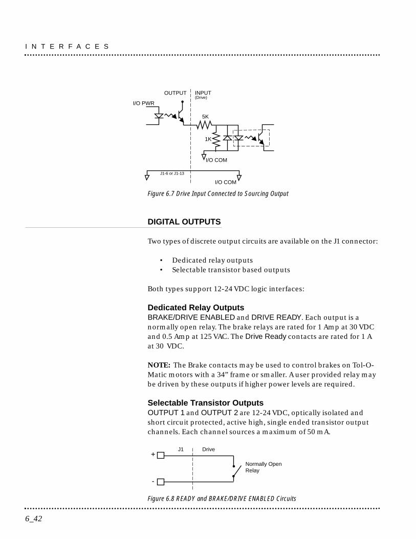
Figure 6.7 Drive Input Connected to Sourcing Output
DIGITAL OUTPUTS
Two types of discrete output circuits are available on the J1 connector:
• Dedicated relay outputs• Selectable transistor based outputs
Both types support 12-24 VDC logic interfaces:
Dedicated Relay OutputsBRAKE/DRIVE ENABLED and DRIVE READY. Each output is anormally open relay. The brake relays are rated for 1 Amp at 30 VDCand 0.5 Amp at 125 VAC. The Drive Ready contacts are rated for 1 Aat 30 VDC.
NOTE: The Brake contacts may be used to control brakes on Tol-O-Matic motors with a 34” frame or smaller. A user provided relay maybe driven by these outputs if higher power levels are required.
Selectable Transistor OutputsOUTPUT 1 and OUTPUT 2 are 12-24 VDC, optically isolated andshort circuit protected, active high, single ended transistor outputchannels. Each channel sources a maximum of 50 mA.
Figure 6.8 READY and BRAKE/DRIVE ENABLED Circuits
J1 Drive
Normally OpenRelay
+
-
(Drive)OUTPUT INPUT
5K
1K
I/O COM
I/O PWR
I/O COM
J1-6 or J1-13
I N T E R F A C E S
6_42
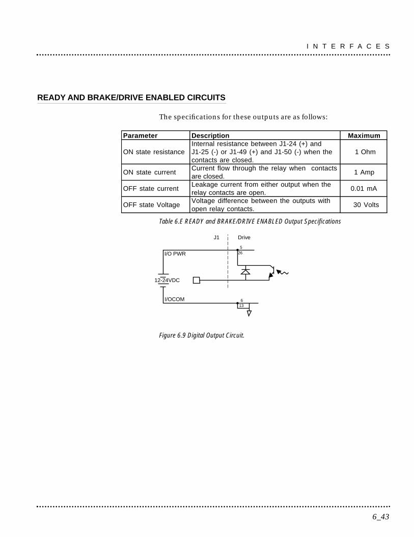
READY AND BRAKE/DRIVE ENABLED CIRCUITS
The specifications for these outputs are as follows:
Table 6.E READY and BRAKE/DRIVE ENABLED Output Specifications
Figure 6.9 Digital Output Circuit.
265
12-24VDC
6I/OCOM
I/O PWR
J1 Drive
13
Parameter Description Maximum
ON state resistanceInternal resistance between J1-24 (+) andJ1-25 (-) or J1-49 (+) and J1-50 (-) when thecontacts are closed.
1 Ohm
ON state currentCurrent flow through the relay when contactsare closed.
1 Amp
OFF state currentLeakage current from either output when therelay contacts are open.
0.01 mA
OFF state VoltageVoltage difference between the outputs withopen relay contacts.
30 Volts
6_43
I N T E R F A C E S
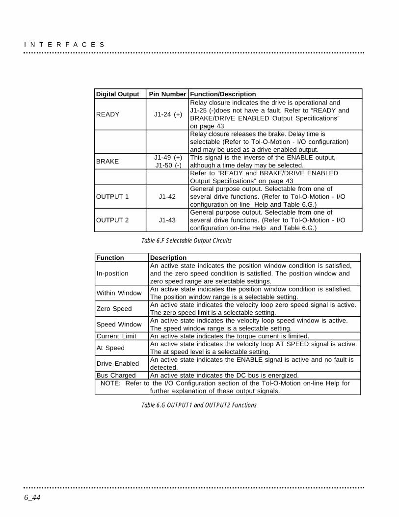
Table 6.F Selectable Output Circuits
Table 6.G OUTPUT1 and OUTPUT2 Functions
Function Description
In-positionAn active state indicates the position window condition is satisfied,and the zero speed condition is satisfied. The position window andzero speed range are selectable settings.
Within WindowAn active state indicates the position window condition is satisfied.The position window range is a selectable setting.
Zero SpeedAn active state indicates the velocity loop zero speed signal is active.The zero speed limit is a selectable setting.
Speed WindowAn active state indicates the velocity loop speed window is active.The speed window range is a selectable setting.
Current Limit An active state indicates the torque current is limited.
At SpeedAn active state indicates the velocity loop AT SPEED signal is active.The at speed level is a selectable setting.
Drive EnabledAn active state indicates the ENABLE signal is active and no fault isdetected.
Bus Charged An active state indicates the DC bus is energized.NOTE: Refer to the I/O Configuration section of the Tol-O-Motion on-line Help for
further explanation of these output signals.
Digital Output Pin Number Function/Description
READY J1-24 (+)
Relay closure indicates the drive is operational andJ1-25 (-)does not have a fault. Refer to “READY andBRAKE/DRIVE ENABLED Output Specifications”on page 43Relay closure releases the brake. Delay time isselectable (Refer to Tol-O-Motion - I/O configuration)and may be used as a drive enabled output.
BRAKEJ1-49 (+)J1-50 (-)
This signal is the inverse of the ENABLE output,although a time delay may be selected.Refer to “READY and BRAKE/DRIVE ENABLEDOutput Specifications” on page 43
OUTPUT 1 J1-42General purpose output. Selectable from one ofseveral drive functions. (Refer to Tol-O-Motion - I/Oconfiguration on-line Help and Table 6.G.)
OUTPUT 2 J1-43General purpose output. Selectable from one ofseveral drive functions. (Refer to Tol-O-Motion - I/Oconfiguration on-line Help and Table 6.G.)
I N T E R F A C E S
6_44
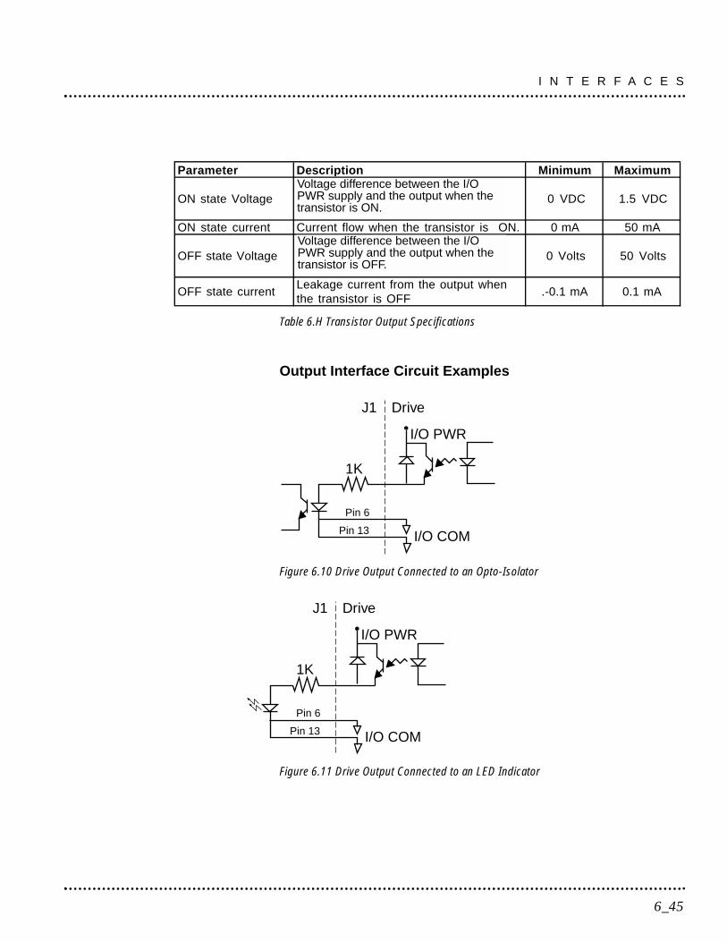
Table 6.H Transistor Output Specifications
Output Interface Circuit Examples
Figure 6.10 Drive Output Connected to an Opto-Isolator
Figure 6.11 Drive Output Connected to an LED Indicator
DriveJ1
I/O PWR
Pin 13
Pin 6
I/O COM
1K
DriveJ1
I/O PWR
Pin 13
Pin 6
I/O COM
1K
Parameter Description Minimum Maximum
ON state VoltageVoltage difference between the +24VDC supply and the output when thetransistor is ON.
0 VDC 1.5 VDC
ON state current Current flow when the transistor is ON. 0 mA 50 mA
OFF state VoltageVoltage difference between the +24VDC supply and the output when thetransistor is OFF.
0 Volts 50 Volts
OFF state currentLeakage current from the output whenthe transistor is OFF
.-0.1 mA 0.1 mA
6_45
I N T E R F A C E S
Voltage difference between the I/OPWR supply and the output when thetransistor is ON.
Voltage difference between the I/OPWR supply and the output when thetransistor is OFF.
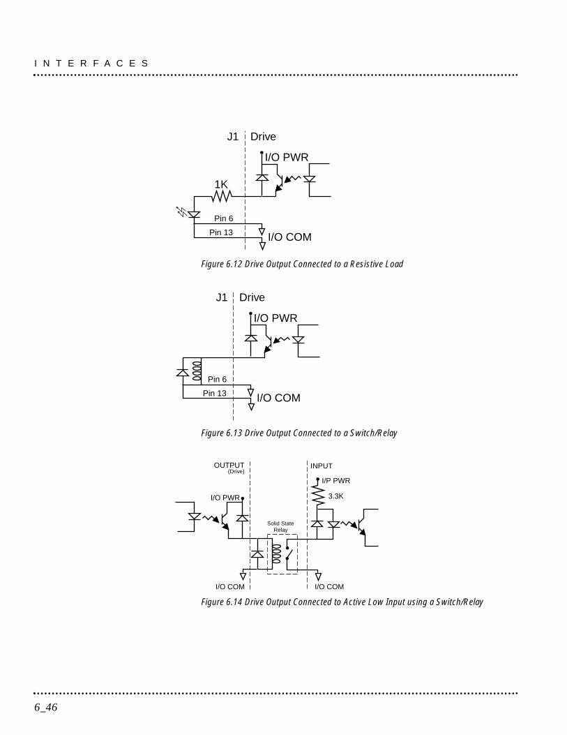
Figure 6.12 Drive Output Connected to a Resistive Load
Figure 6.13 Drive Output Connected to a Switch/Relay
Figure 6.14 Drive Output Connected to Active Low Input using a Switch/Relay
Solid StateRelay
(Drive)
I/O COM I/O COM
3.3K
I/P PWR
I/O PWR
INPUTOUTPUT
DriveJ1
I/O PWR
Pin 13
Pin 6
I/O COM
DriveJ1
I/O PWR
Pin 13
Pin 6
I/O COM
1K
I N T E R F A C E S
6_46
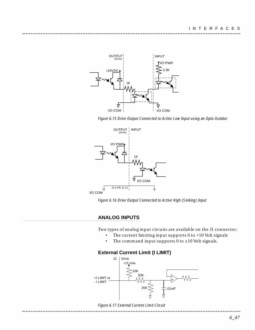
Figure 6.15 Drive Output Connected to Active Low Input using an Opto-Isolator
Figure 6.16 Drive Output Connected to Active High (Sinking) Input
ANALOG INPUTS
Two types of analog input circuits are available on the J1 connector:• The current limiting input supports 0 to +10 Volt signals• The command input supports 0 to ±10 Volt signals.
External Current Limit (I LIMIT)
Figure 6.17 External Current Limit Circuit
20K
+I LIMIT or- I LIMIT
DriveJ1
10K
.01mF
20K -+
+15 Volts
(Drive)
J1-6 OR J1-13
I/O COM
I/O COM
I/O PWR
OUTPUT INPUT
1K
(Drive)
I/O COM I/O COM
3.3K
I/O PWR
+24VDC
INPUTOUTPUT
1K
6_47
I N T E R F A C E S

ILIMIT limits the current, which provides torque, to the motor. Therange is 0 to +10 Volts (where 10 Volts corresponds to maximumdrive current).The analog I LIMIT signal is converted into a digitalword by a 10-bit ADC (analog to digital converter). If the I LIMITinput is not connected, current is not limited.
Table 6.I Analog Inputs (I LIMIT)
Table 6.J External Current Limit Input Specification
Command Input
Figure 6.18 Analog COMMAND Input Circuit
The analog command signal to the drive has a range of ±10 Volts. Thesignal is either a torque or a velocity command, depending on thesoftware configuration of the drive. The differential input is processedby a 16 bit analog to digital converter (ADC) to produce a digital value.
DriveJ1 10K
.01uF
-+
10K
.01uF
10K
10K10K
10K
ANALOGCOMMAND
20K
COMMAND +
COMMAND -
Parameter Description Minimum MaximumMaximumCurrent
Short circuit between the input and ground. -1.5 mA
Input SignalRange
Allowable voltage applied to the input 0 Volts +10 Volts
Analog Input Pin
NumberFunction/Description
Current Limit(I LIMIT)
J1-27 Limits the peak current command, which produces torque.
I N T E R F A C E S
6_48
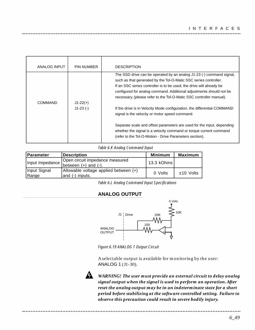
Table 6.K Analog Command Input
Table 6.L Analog Command Input Specifications
ANALOG OUTPUT
Figure 6.19 ANALOG 1 Output Circuit
A selectable output is available for monitoring by the user:ANALOG 1 (J1-30).
WARNING! The user must provide an external circuit to delay analogsignal output when the signal is used to perform an operation. Afterreset the analog output may be in an indeterminate state for a shortperiod before stabilizing at the software controlled setting. Failure toobserve this precaution could result in severe bodily injury.
J1
100-+
10K
-5 Volts
ANALOGOUTPUT
20KDrive
Parameter Description Minimum Maximum
Input ImpedanceOpen circuit impedance measuredbetween (+) and (-).
13.3 kOhms
Input SignalRange
Allowable voltage applied between (+)and (-) inputs.
0 Volts ±10 Volts
J1-22(+)
J1-23 (-)
The SSD drive can be operated by an analog J1-23 (-) command signal,
such as that generated by the Tol-O-Matic SSC series controller.
If an SSC series controller is to be used, the drive will already be
configured for analog command. Additional adjustments should not be
necessary. (please refer to the Tol-O-Matic SSC controller manual).
If the drive is in Velocity Mode configuration, the differential COMMAND
signal is the velocity or motor speed command.
Separate scale and offset parameters are used for the input, depending
whether the signal is a velocity command or torque current command
(refer to the Tol-O-Motion - Drive Parameters section).
PIN NUMBER DESCRIPTION
COMMAND
ANALOG INPUT
6_49
I N T E R F A C E S
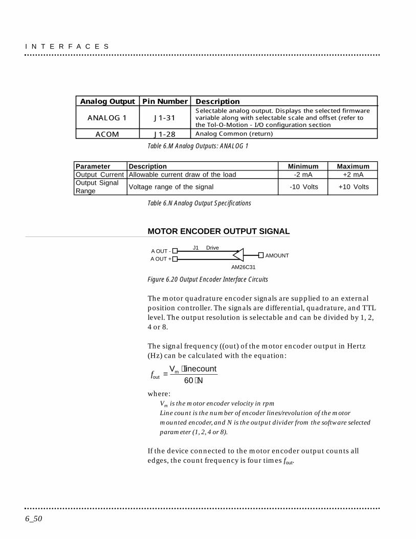
Table 6.M Analog Outputs: ANALOG 1
Table 6.N Analog Output Specifications
MOTOR ENCODER OUTPUT SIGNAL
Figure 6.20 Output Encoder Interface Circuits
The motor quadrature encoder signals are supplied to an externalposition controller. The signals are differential, quadrature, and TTLlevel. The output resolution is selectable and can be divided by 1, 2,4 or 8.
The signal frequency ((out) of the motor encoder output in Hertz(Hz) can be calculated with the equation:
where:Vm is the motor encoder velocity in rpmLine count is the number of encoder lines/revolution of the motormounted encoder, and N is the output divider from the software selectedparameter (1, 2, 4 or 8).
If the device connected to the motor encoder output counts alledges, the count frequency is four times fout.
foutmV linecount
N= ⋅
⋅60
A OUT -A OUT +
AMOUNT
AM26C31
J1 Drive
Parameter Description Minimum MaximumOutput Current Allowable current draw of the load -2 mA +2 mAOutput SignalRange
Voltage range of the signal -10 Volts +10 Volts
Analog Output
ANALOG 1
ACOM
Pin Number
J1-31
J1-28
DescriptionSelectable analog output. Displays the selected firmwarevariable along with selectable scale and offset (refer tothe Tol-O-Motion - I/O configuration sectionAnalog Common (return)
I N T E R F A C E S
6_50
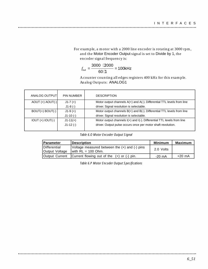
For example, a motor with a 2000 line encoder is rotating at 3000 rpm,and the Motor Encoder Output signal is set to Divide by 1, theencoder signal frequency is:
A counter counting all edges registers 400 kHz for this example.Analog Outputs: ANALOG1
Table 6.O Motor Encoder Output Signal
Table 6.P Motor Encoder Output Specifications
Parameter Description Minimum MaximumDifferentialOutput Voltage
Voltage measured between the (+) and (-) pinswith RL = 100 Ohm.
2.0 Volts
Output Current Current flowing out of the (+) or (-) pin. -20 mA +20 mA
J1-7 (+)
J1-8 (-)
J1-9 (+)
J1-10 (-)
J1-11(+)
J1-12 (-)
Motor output channels A(+) and A(-). Differential TTL levels from line
driver. Signal resolution is selectable.
Motor output channels B(+) and B(-). Differential TTL levels from line
driver. Signal resolution is selectable.
Motor output channels I(+) and I(-). Differential TTL levels from line
driver. Output pulse occurs once per motor shaft revolution.
PIN NUMBER DESCRIPTION
AOUT (+) AOUT(-)
BOUT(+) BOUT(-)
IOUT (+) IOUT(-)
ANALOG OUTPUT
fout =⋅⋅
=3000 2000
60 1100kHz
6_51
I N T E R F A C E S
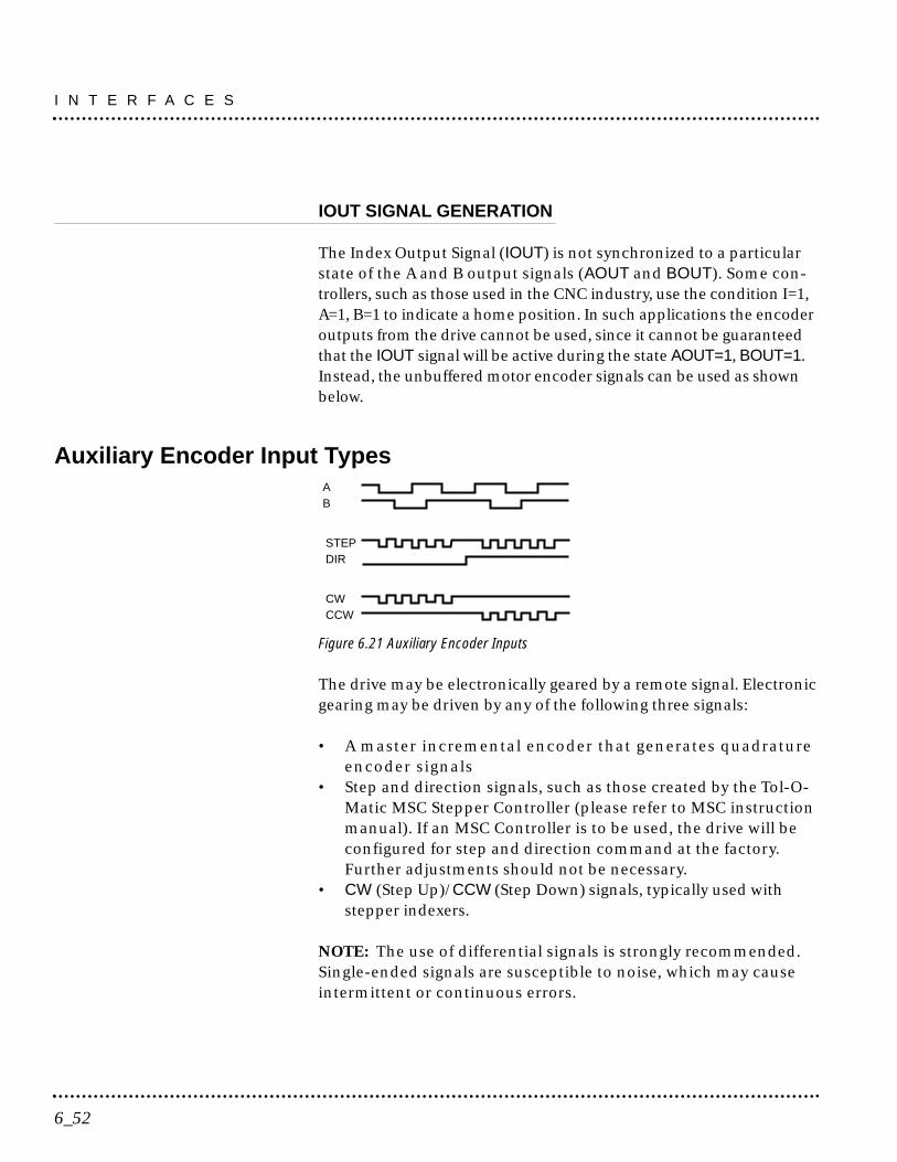
IOUT SIGNAL GENERATION
The Index Output Signal (IOUT) is not synchronized to a particularstate of the A and B output signals (AOUT and BOUT). Some con-trollers, such as those used in the CNC industry, use the condition I=1,A=1, B=1 to indicate a home position. In such applications the encoderoutputs from the drive cannot be used, since it cannot be guaranteedthat the IOUT signal will be active during the state AOUT=1, BOUT=1.Instead, the unbuffered motor encoder signals can be used as shownbelow.
Auxiliary Encoder Input Types
Figure 6.21 Auxiliary Encoder Inputs
The drive may be electronically geared by a remote signal. Electronicgearing may be driven by any of the following three signals:
• A master incremental encoder that generates quadratureencoder signals
• Step and direction signals, such as those created by the Tol-O-Matic MSC Stepper Controller (please refer to MSC instructionmanual). If an MSC Controller is to be used, the drive will beconfigured for step and direction command at the factory.Further adjustments should not be necessary.
• CW (Step Up)/CCW (Step Down) signals, typically used withstepper indexers.
NOTE: The use of differential signals is strongly recommended.Single-ended signals are susceptible to noise, which may causeintermittent or continuous errors.
AB
STEPDIR
CWCCW
I N T E R F A C E S
6_52
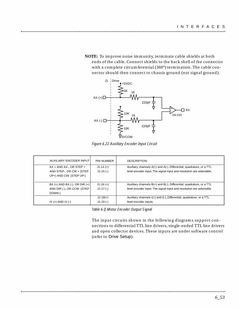
NOTE: To improve noise immunity, terminate cable shields at bothends of the cable. Connect shields to the back shell of the connectorwith a complete circumferential (360°) termination. The cable con-nector should then connect to chassis ground (not signal ground).
Figure 6.22 Auxiliary Encoder Input Circuit
Table 6.Q Motor Encoder Output Signal
The input circuits shown in the following diagrams support con-nections to differential TTL line drivers, single-ended TTL line driversand open collector devices. These inputs are under software control(refer to Drive Setup).
J1-14 (+)
J1-15 (-)
J1-16 (+)
J1-17 (-)
J1-18(+)
J1-19 (-)
Auxiliary channels A(+) and A(-). Differential, quadrature, or a TTL
level encoder input. The signal input and resolution are selectable.
Auxiliary channels B(+) and B(-). Differential, quadrature, or a TTL
level encoder input. The signal input and resolution are selectable
Auxiliary channels I(+) and I(-). Differential, quadrature, or a TTL
level encoder inputs.
PIN NUMBER DESCRIPTION
AX + AND AX-, OR STEP +
AND STEP-, OR CW + (STEP
UP+) AND CW- (STEP UP-)
BX (+) AND BX (-), OR DIR (+)
AND DIR (-), OR CCW- (STEP
DOWN-)
IX (+) AND IX (-)
AUXILIARY ENCODER INPUT
DriveJ1
1K
220pF
+-
1K
220pF
26LS33
AX10K
AX (+)
AX (-)
10K
5K
+5VDC
5VCOM
6_53
I N T E R F A C E S
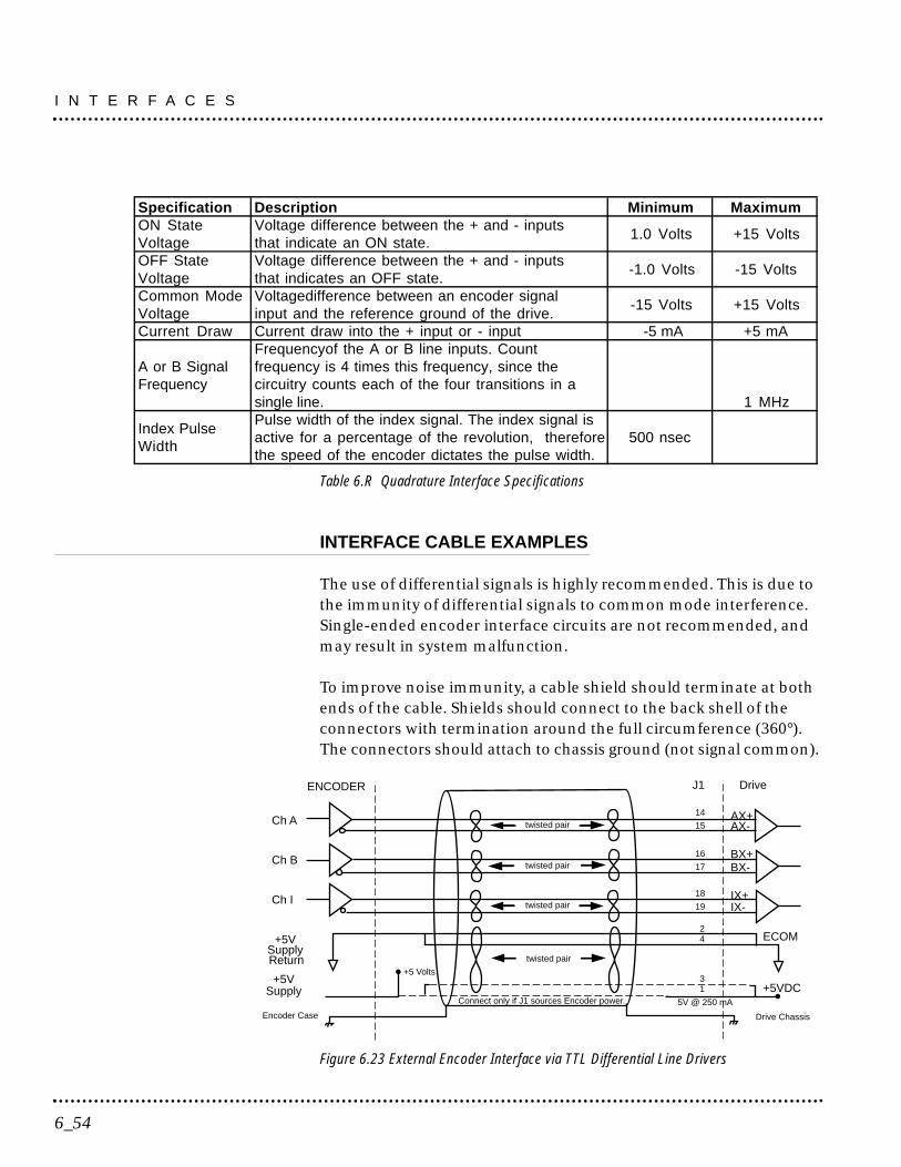
Table 6.R Quadrature Interface Specifications
INTERFACE CABLE EXAMPLES
The use of differential signals is highly recommended. This is due tothe immunity of differential signals to common mode interference.Single-ended encoder interface circuits are not recommended, andmay result in system malfunction.
To improve noise immunity, a cable shield should terminate at bothends of the cable. Shields should connect to the back shell of theconnectors with termination around the full circumference (360°).The connectors should attach to chassis ground (not signal common).
Figure 6.23 External Encoder Interface via TTL Differential Line Drivers
Ch A
ENCODER
AX+AX-
14
15
J1 Drive
twisted pair
Ch B BX+BX-
16
17twisted pair
Ch I IX+IX-
18
19twisted pair
Drive ChassisEncoder Case
24+5V
SupplyReturn
+5 Volts
13+5V
Supply +5VDCConnect only if J1 sources Encoder power. 5V @ 250 mA
ECOM
twisted pair
Specification Description Minimum MaximumON StateVoltage
Voltage difference between the + and - inputsthat indicate an ON state.
1.0 Volts +15 Volts
OFF StateVoltage
Voltage difference between the + and - inputsthat indicates an OFF state.
-1.0 Volts -15 Volts
Common ModeVoltage
Voltagedifference between an encoder signalinput and the reference ground of the drive.
-15 Volts +15 Volts
Current Draw Current draw into the + input or - input -5 mA +5 mA
A or B SignalFrequency
Frequencyof the A or B line inputs. Countfrequency is 4 times this frequency, since thecircuitry counts each of the four transitions in asingle line. 1 MHz
Index PulseWidth
Pulse width of the index signal. The index signal isactive for a percentage of the revolution, thereforethe speed of the encoder dictates the pulse width.
500 nsec
I N T E R F A C E S
6_54
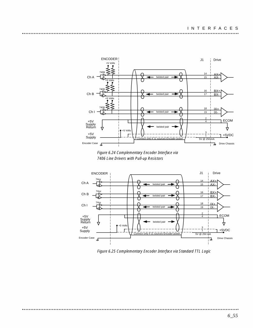
Figure 6.24 Complementary Encoder Interface via7406 Line Drivers with Pull-up Resistors
Figure 6.25 Complementary Encoder Interface via Standard TTL Logic
Ch A
ENCODER
AX+AX-
14
15
J1 Drive
twisted pair
Ch B BX+BX-
16
17twisted pair
Ch I IX+IX-
18
19twisted pair
Drive ChassisEncoder Case
24+5V
SupplyReturn
+5 Volts
13+5V
Supply +5VDCConnect only if J1 sources Encoder power. 5V @ 250 mA
ECOM
twisted pair
74xx
74xx
74xx
Ch A
ENCODER
AX+AX-
14
15
J1 Drive
twisted pair
Ch BBX+BX-
1617twisted pair
Ch IIX+IX-
18
19twisted pair
Drive ChassisEncoder Case
24+5V
SupplyReturn
+5 Volts
13+5V
Supply+5VDC
Connect only if J1 sources Encoder power. 5V @ 250 mA
ECOM
twisted pair
+5 Volts
+5 Volts
+5 Volts
7406
7406
7406
6_55
I N T E R F A C E S
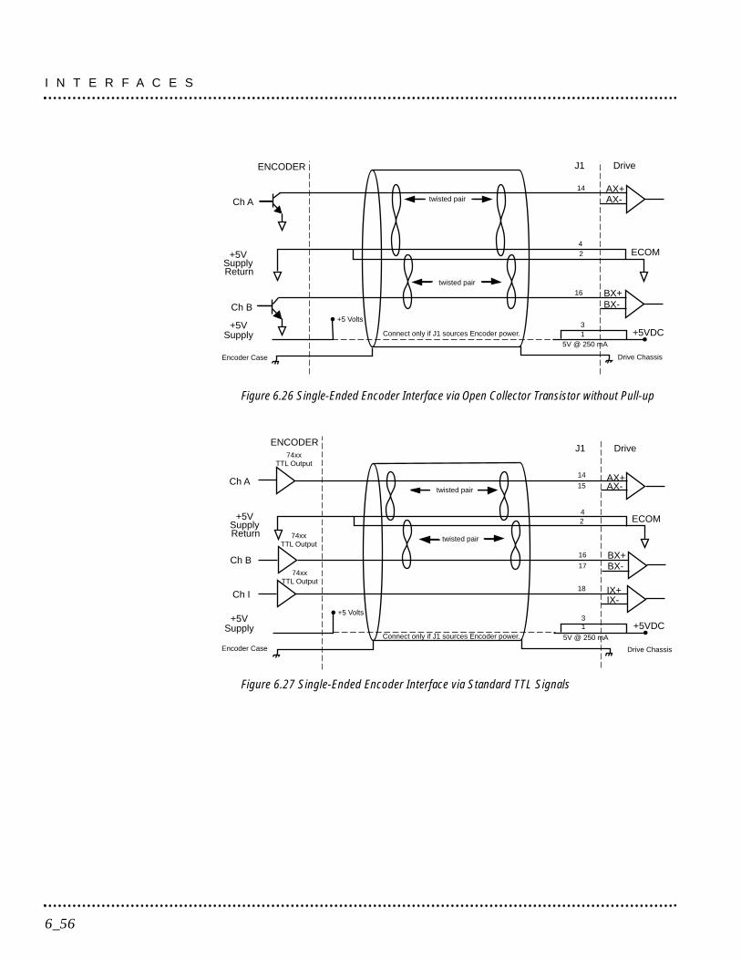
Figure 6.26 Single-Ended Encoder Interface via Open Collector Transistor without Pull-up
Figure 6.27 Single-Ended Encoder Interface via Standard TTL Signals
Ch A
ENCODER
AX+AX-
14
15
J1 Drive
twisted pair
Ch B BX+BX-
16
17
twisted pair
Ch I IX+IX-
18
Drive ChassisEncoder Case
+5 Volts
13+5V
Supply +5VDCConnect only if J1 sources Encoder power. 5V @ 250 mA
74xxTTL Output
74xxTTL Output
74xxTTL Output
24+5V
SupplyReturn
ECOM
Ch A
ENCODER
AX+AX-
14
J1 Drive
twisted pair
Ch B
BX+BX-
16
Drive ChassisEncoder Case
24
+5VSupplyReturn
+5 Volts
13+5V
Supply +5VDCConnect only if J1 sources Encoder power.
5V @ 250 mA
ECOM
twisted pair
I N T E R F A C E S
6_56

Figure 6.28 Single-Ended Encoder Interface via Open Collector Transistorwith 5 VDC to 12 VDC Pull-up
Figure 6.29 Single-Ended Encoder Interface via Open Collector Transistorwith 24 VDC Pull-up
Ch A
ENCODERJ1 Drive
Ch B
BX+BX-
16
Ch I
IX+IX-
18
AX+AX-
14
twisted pair
24
SupplyReturn
ECOM
twisted pair24VDC
24VDC
24VDC
IN7515.1V
IN7515.1V
IN7515.1V
Encoder Case Drive Chassis
Ch A
ENCODER J1 Drive
Ch B
BX+BX-
16
Ch I
IX+IX-
18
AX+AX-
14
twisted pair
24
SupplyReturn
ECOM
twisted pair
5-12 Volts
Encoder Case Drive Chassis
5-12 Volts
5-12 Volts
6_57
I N T E R F A C E S
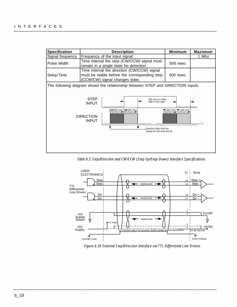
Table 6.S Step/Direction and CW/CCW (Step Up/Step Down) Interface Specifications
Figure 6.30 External Step/Direction Interface via TTL Differential Line Drivers
USERELECTRONICS
Step +Step -
14
15
J1 Drive
twisted pair
16
17twisted pair
Drive ChassisEncoder Case
24+5V
SupplyReturn
+5 Volts
13
+5VSupply
+5VDCConnect only if J1 sources +5VDC power to user electronics 5V @ 250 mA
ECOM
twisted pair
StepStep
DirDir
Dir +Dir -
TTLDifferentialLine Drivers
I N T E R F A C E S
6_58
Specification Description Minimum MaximumSignal frequency Frequency of the input signal 1 Mhz
Pulse WidthTime interval the step (CW/CCW) signal mustremain in a single state for detection.
500 nsec
Setup TimeTime interval the direction (CW/CCW) signalmust be stable before the corresponding step(CCW/CW) signal changes state.
500 nsec.
The following diagram shows the relationship between STEP and DIRECTION inputs.
STEPINPUT
DIRECTIONINPUT
Direction data must besteady for this time period.
500 nsecminimum
500 nsecminimum
500 nsec in eitherhigh or low state
500 nsecminimum
500 nsecminimum
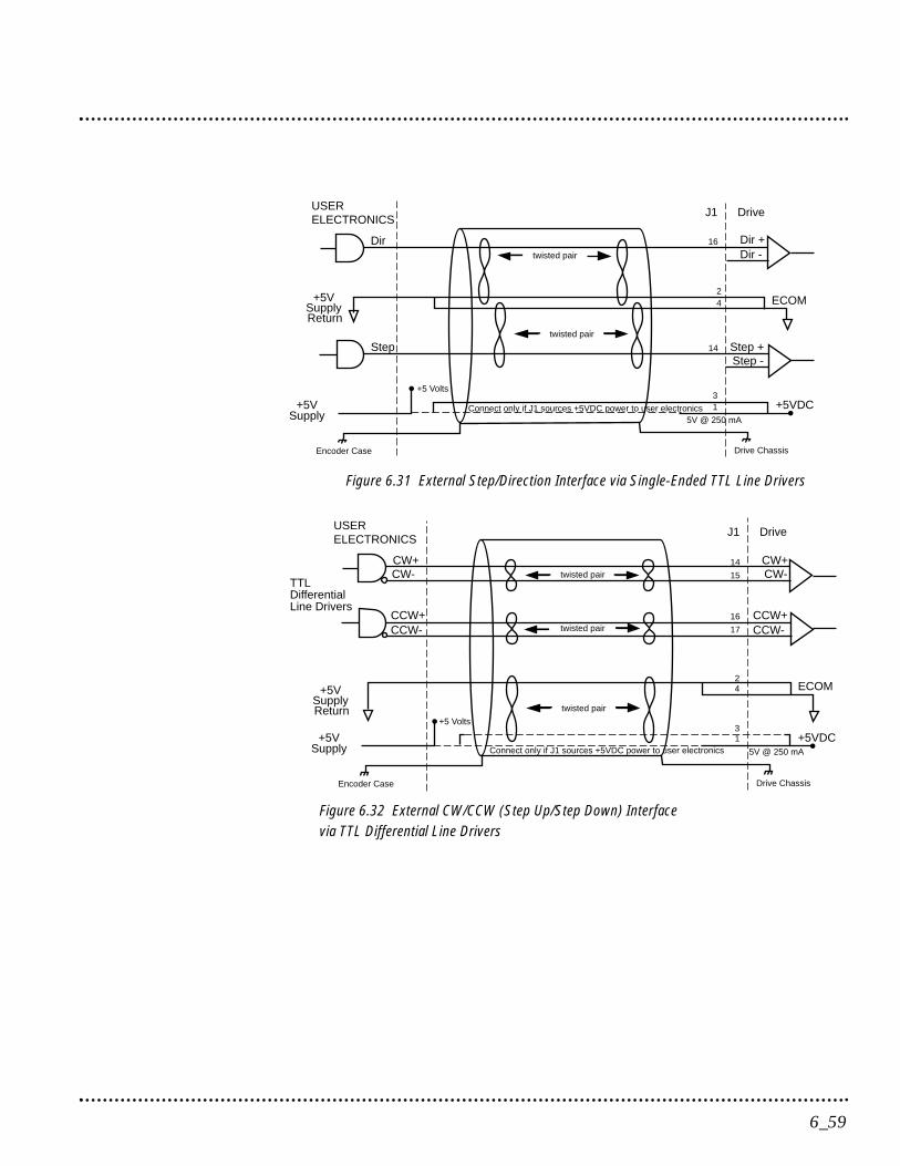
Figure 6.31 External Step/Direction Interface via Single-Ended TTL Line Drivers
Figure 6.32 External CW/CCW (Step Up/Step Down) Interfacevia TTL Differential Line Drivers
USERELECTRONICS
CW+CW-
14
15
J1 Drive
twisted pair
16
17twisted pair
Drive ChassisEncoder Case
24+5V
SupplyReturn
+5 Volts
13
+5VSupply
+5VDCConnect only if J1 sources +5VDC power to user electronics 5V @ 250 mA
ECOM
twisted pair
CW+CW-
CCW+CCW-
CCW+CCW-
TTLDifferentialLine Drivers
USERELECTRONICS
Step +Step -
16
J1 Drive
twisted pair
14
Drive ChassisEncoder Case
24
+5 Volts
13
+5VSupply
+5VDCConnect only if J1 sources +5VDC power to user electronics5V @ 250 mA
Dir
Step
Dir +Dir -
+5VSupplyReturn
ECOM
twisted pair
6_59
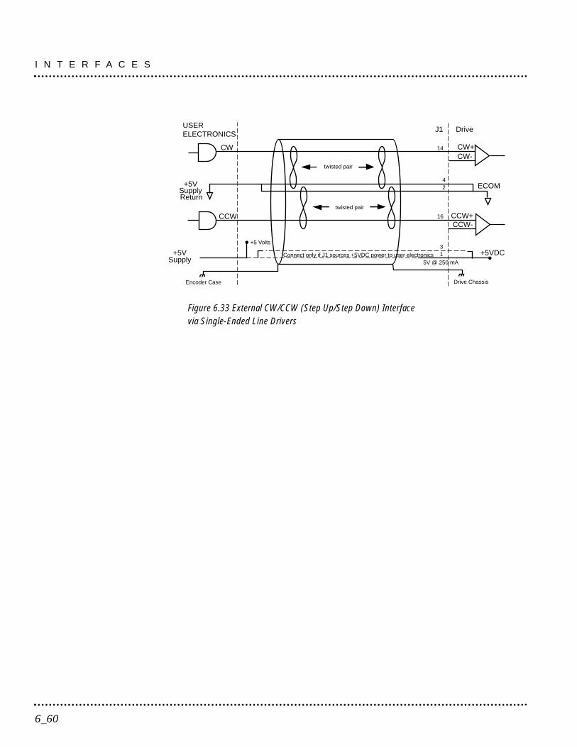
Figure 6.33 External CW/CCW (Step Up/Step Down) Interfacevia Single-Ended Line Drivers
USERELECTRONICS
CCW+CCW-
14
J1 Drive
twisted pair
16
Drive ChassisEncoder Case
42
+5 Volts
13
+5VSupply
+5VDCConnect only if J1 sources +5VDC power to user electronics5V @ 250 mA
CW
CCW
CW+CW-
+5VSupplyReturn
ECOM
twisted pair
I N T E R F A C E S
6_60
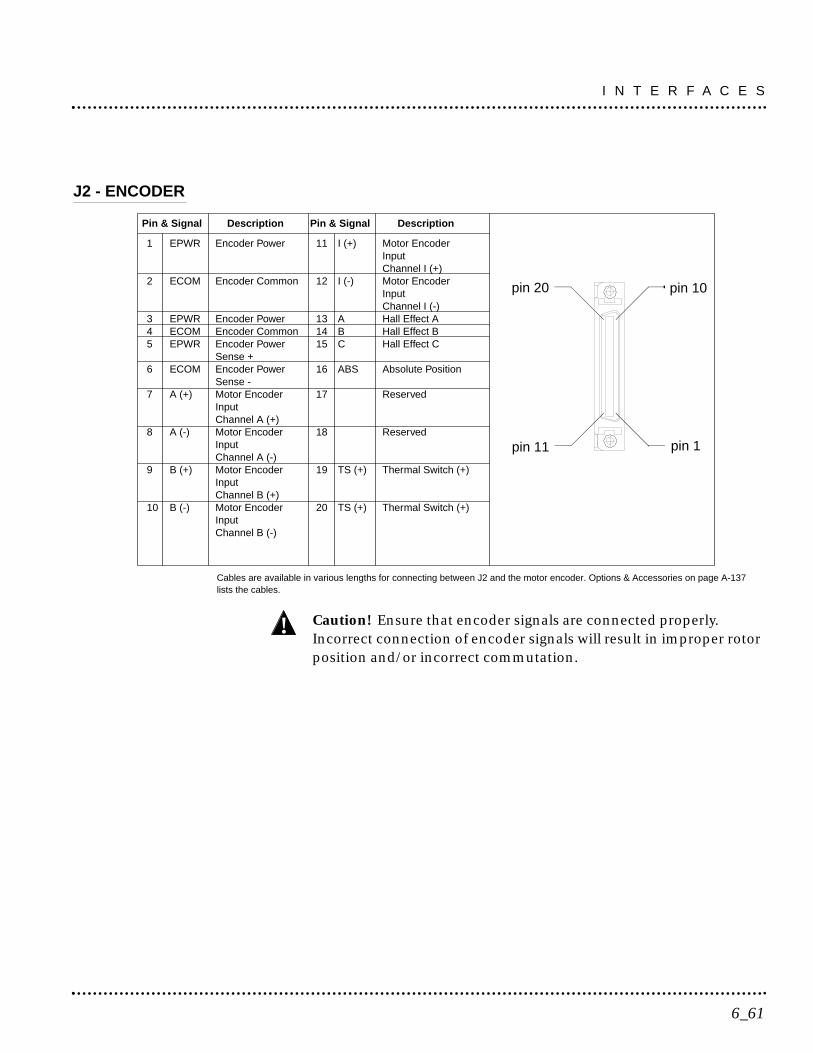
J2 - ENCODER
Cables are available in various lengths for connecting between J2 and the motor encoder. Options & Accessories on page A-137lists the cables.
Caution! Ensure that encoder signals are connected properly.Incorrect connection of encoder signals will result in improper rotorposition and/or incorrect commutation.
!
pin 20 pin 10
pin 1pin 11
1 EPWR Encoder Power 11 I (+) Motor EncoderInputChannel I (+)
2 ECOM Encoder Common 12 I (-) Motor EncoderInputChannel I (-)
3 EPWR Encoder Power 13 A Hall Effect A4 ECOM Encoder Common 14 B Hall Effect B5 EPWR Encoder Power 15 C Hall Effect C
Sense +6 ECOM Encoder Power 16 ABS Absolute Position
Sense -7 A (+) Motor Encoder 17 Reserved
InputChannel A (+)
8 A (-) Motor Encoder 18 ReservedInputChannel A (-)
9 B (+) Motor Encoder 19 TS (+) Thermal Switch (+)InputChannel B (+)
10 B (-) Motor Encoder 20 TS (+) Thermal Switch (+)InputChannel B (-)
Pin & Signal Description Pin & Signal Description
6_61
I N T E R F A C E S
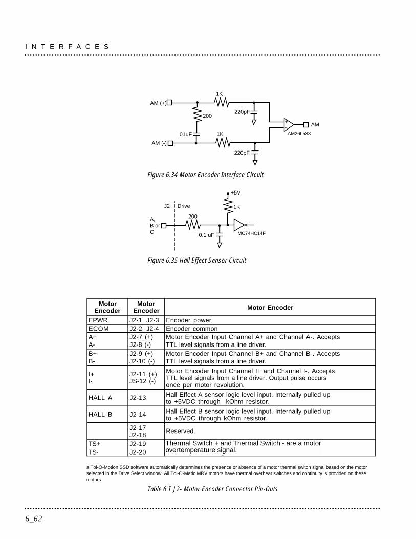
Figure 6.34 Motor Encoder Interface Circuit
Figure 6.35 Hall Effect Sensor Circuit
a Tol-O-Motion SSD software automatically determines the presence or absence of a motor thermal switch signal based on the motorselected in the Drive Select window. All Tol-O-Matic MRV motors have thermal overheat switches and continuity is provided on thesemotors.
Table 6.T J2- Motor Encoder Connector Pin-Outs
MotorEncoder
MotorEncoder Motor Encoder
EPWR J2-1 J2-3 Encoder powerECOM J2-2 J2-4 Encoder commonA+ J2-7 (+) Motor Encoder Input Channel A+ and Channel A-. AcceptsA- J2-8 (-) TTL level signals from a line driver.B+ J2-9 (+) Motor Encoder Input Channel B+ and Channel B-. AcceptsB- J2-10 (-) TTL level signals from a line driver.
I+I-
J2-11 (+)JS-12 (-)
Motor Encoder Input Channel I+ and Channel I-. AcceptsTTL level signals from a line driver. Output pulse occursonce per motor revolution.
HALL A J2-13 Hall Effect A sensor logic level input. Internally pulled upto +5VDC through kOhm resistor.
HALL B J2-14 Hall Effect B sensor logic level input. Internally pulled upto +5VDC through kOhm resistor.
J2-17J2-18
Reserved.
TS+ J2-19 Thermal Switch + and Thermal Siwtch - are a motorTS- J2-20 overtemperature signal.
200
0.1 uF MC74HC14F
A,B orC
J2 Drive 1K
+5V
1K
220pF
+-
1K
220pF
AM26L533
AM
200
AM (+)
AM (-)
.01uF
I N T E R F A C E S
6_62
Thermal Switch + and Thermal Switch - are a motorovertemperature signal.
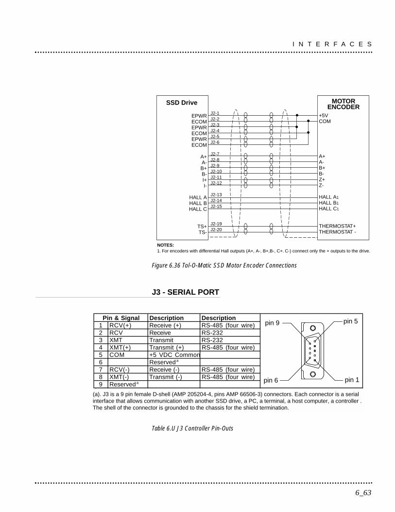
Figure 6.36 Tol-O-Matic SSD Motor Encoder Connections
J3 - SERIAL PORT
Table 6.U J3 Controller Pin-Outs
Pin & Signal Description Description1 RCV(+) Receive (+) RS-485 (four wire)2 RCV Receive RS-2323 XMT Transmit RS-2324 XMT(+) Transmit (+) RS-485 (four wire)5 COM +5 VDC Common6 Reserveda
7 RCV(-) Receive (-) RS-485 (four wire)8 XMT(-) Transmit (-) RS-485 (four wire)9 Reserveda
a J5 is a 9 pin female D-shell (AMP 205204-4, pins AMP 66506-3) connectors. Each connector is a interface that allows communication with another SSD drive, a PC, a terminal, a host computer, a or an optional TouchPad. The shell of the connector is grounded to the chassis for shield terminati
EPWRECOMEPWRECOMEPWRECOM
A+A-B+B-I+I-
HALL AHALL BHALL C
TS+TS-
+5VCOM
A+A-B+B-Z+Z-
HALL A1
HALL B1
HALL C1
THERMOSTAT+THERMOSTAT -
J2-1J2-2J2-3J2-4J2-5J2-6
J2-7J2-8J2-9J2-10J2-11J2-12
J2-13J2-14J2-15
J2-19J2-20
NOTES:1. For encoders with differential Hall outputs (A+, A-, B+,B-, C+. C-) connect only the + outputs to the drive.
SSD Drive MOTORENCODER
6_63
I N T E R F A C E S
pin 9
pin 6
pin 5
pin 1
(a). J3 is a 9 pin female D-shell (AMP 205204-4, pins AMP 66506-3) connectors. Each connector is a serialinterface that allows communication with another SSD drive, a PC, a terminal, a host computer, a controller .The shell of the connector is grounded to the chassis for the shield termination.
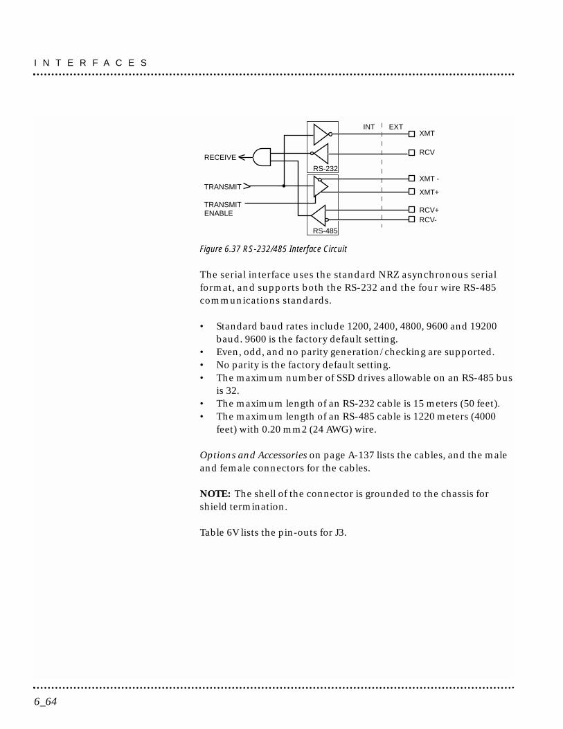
Figure 6.37 RS-232/485 Interface Circuit
The serial interface uses the standard NRZ asynchronous serialformat, and supports both the RS-232 and the four wire RS-485communications standards.
• Standard baud rates include 1200, 2400, 4800, 9600 and 19200baud. 9600 is the factory default setting.
• Even, odd, and no parity generation/checking are supported.• No parity is the factory default setting.• The maximum number of SSD drives allowable on an RS-485 bus
is 32.• The maximum length of an RS-232 cable is 15 meters (50 feet).• The maximum length of an RS-485 cable is 1220 meters (4000
feet) with 0.20 mm2 (24 AWG) wire.
Options and Accessories on page A-137 lists the cables, and the maleand female connectors for the cables.
NOTE: The shell of the connector is grounded to the chassis forshield termination.
Table 6V lists the pin-outs for J3.
RECEIVE
TRANSMIT
TRANSMITENABLE
XMTINT
RS-232
RS-485
EXT
RCV
XMT -
XMT+
RCV+RCV-
I N T E R F A C E S
6_64
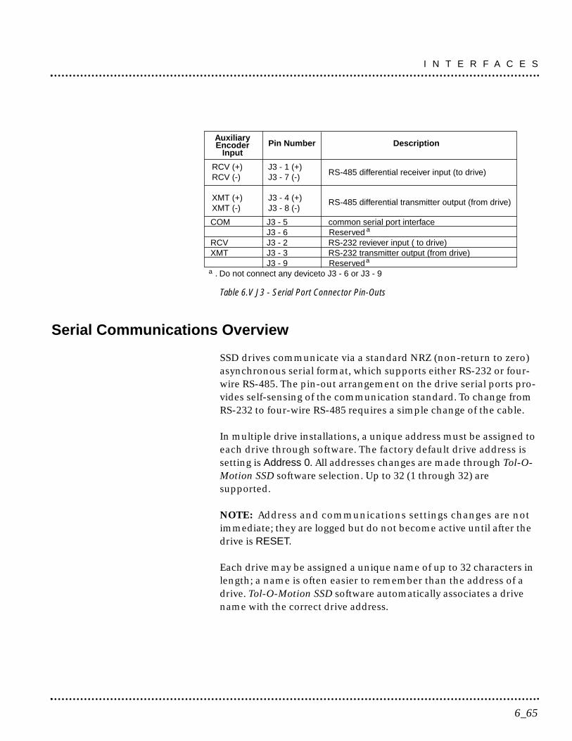
Table 6.V J3 - Serial Port Connector Pin-Outs
Serial Communications Overview
SSD drives communicate via a standard NRZ (non-return to zero)asynchronous serial format, which supports either RS-232 or four-wire RS-485. The pin-out arrangement on the drive serial ports pro-vides self-sensing of the communication standard. To change fromRS-232 to four-wire RS-485 requires a simple change of the cable.
In multiple drive installations, a unique address must be assigned toeach drive through software. The factory default drive address issetting is Address 0. All addresses changes are made through Tol-O-Motion SSD software selection. Up to 32 (1 through 32) aresupported.
NOTE: Address and communications settings changes are notimmediate; they are logged but do not become active until after thedrive is RESET.
Each drive may be assigned a unique name of up to 32 characters inlength; a name is often easier to remember than the address of adrive. Tol-O-Motion SSD software automatically associates a drivename with the correct drive address.
RCV (+) J3 - 1 (+)RCV (-) J3 - 7 (-)
XMT (+) J3 - 4 (+)XMT (-) J3 - 8 (-)
AuxiliaryEncoder
InputPin Number Description
COM J3 - 5 common serial port interfaceJ3 - 6 Reserved
RCV J3 - 2 RS-232 reviever input ( to drive)XMT J3 - 3 RS-232 transmitter output (from drive)
J3 - 9 Reserved . Do not connect any deviceto J3 - 6 or J3 - 9
RS-485 differential receiver input (to drive)
RS-485 differential transmitter output (from drive)
a
a
a
6_65
I N T E R F A C E S
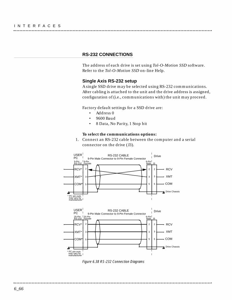
RS-232 CONNECTIONS
The address of each drive is set using Tol-O-Motion SSD software.Refer to the Tol-O-Motion SSD on-line Help.
Single Axis RS-232 setupA single SSD drive may be selected using RS-232 communications.After cabling is attached to the unit and the drive address is assigned,configuration of (i.e., communications with) the unit may proceed.
Factory default settings for a SSD drive are:• Address 0• 9600 Baud• 8 Data, No Parity, 1 Stop bit
To select the communications options:1. Connect an RS-232 cable between the computer and a serial
connector on the drive (J3).
Figure 6.38 RS-232 Connection Diagrams
USER
2
9-Pin
Drive
2
Drive Chassis
PC
33
5
Male
RS-232 CABLE
J3
2
3
5
RCV
XMT
COM
RCV*
XMT*
COM*
* PC pin-outs may vary by manufacturer
9-PinFemale
9-Pin Male Connector to 9-Pin Female Connector9-PinRS-232
5
USER
2
9-Pin
Drive
2
Drive Chassis
PC
33
5
Male
RS-232 CABLE
J5
2
3
5
RCV
XMT
COM
RCV*
XMT*
COM*
* PC pin-outs may vary by manufacturer
25-PinFemale
9-Pin Male Connector to 9-Pin Female Connector25-PinRS-232
5
I N T E R F A C E S
6_66
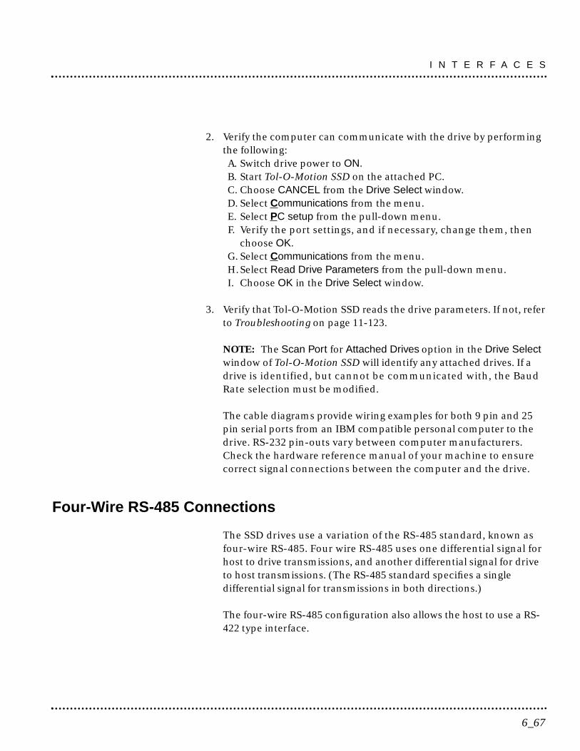
2. Verify the computer can communicate with the drive by performingthe following:A. Switch drive power to ON.B. Start Tol-O-Motion SSD on the attached PC.C. Choose CANCEL from the Drive Select window.D. Select Communications from the menu.E. Select PC setup from the pull-down menu.F. Verify the port settings, and if necessary, change them, then
choose OK.G. Select Communications from the menu.H. Select Read Drive Parameters from the pull-down menu.I. Choose OK in the Drive Select window.
3. Verify that Tol-O-Motion SSD reads the drive parameters. If not, referto Troubleshooting on page 11-123.
NOTE: The Scan Port for Attached Drives option in the Drive Selectwindow of Tol-O-Motion SSD will identify any attached drives. If adrive is identified, but cannot be communicated with, the BaudRate selection must be modified.
The cable diagrams provide wiring examples for both 9 pin and 25pin serial ports from an IBM compatible personal computer to thedrive. RS-232 pin-outs vary between computer manufacturers.Check the hardware reference manual of your machine to ensurecorrect signal connections between the computer and the drive.
Four-Wire RS-485 Connections
The SSD drives use a variation of the RS-485 standard, known asfour-wire RS-485. Four wire RS-485 uses one differential signal forhost to drive transmissions, and another differential signal for driveto host transmissions. (The RS-485 standard specifies a singledifferential signal for transmissions in both directions.)
The four-wire RS-485 configuration also allows the host to use a RS-422 type interface.
6_67
I N T E R F A C E S
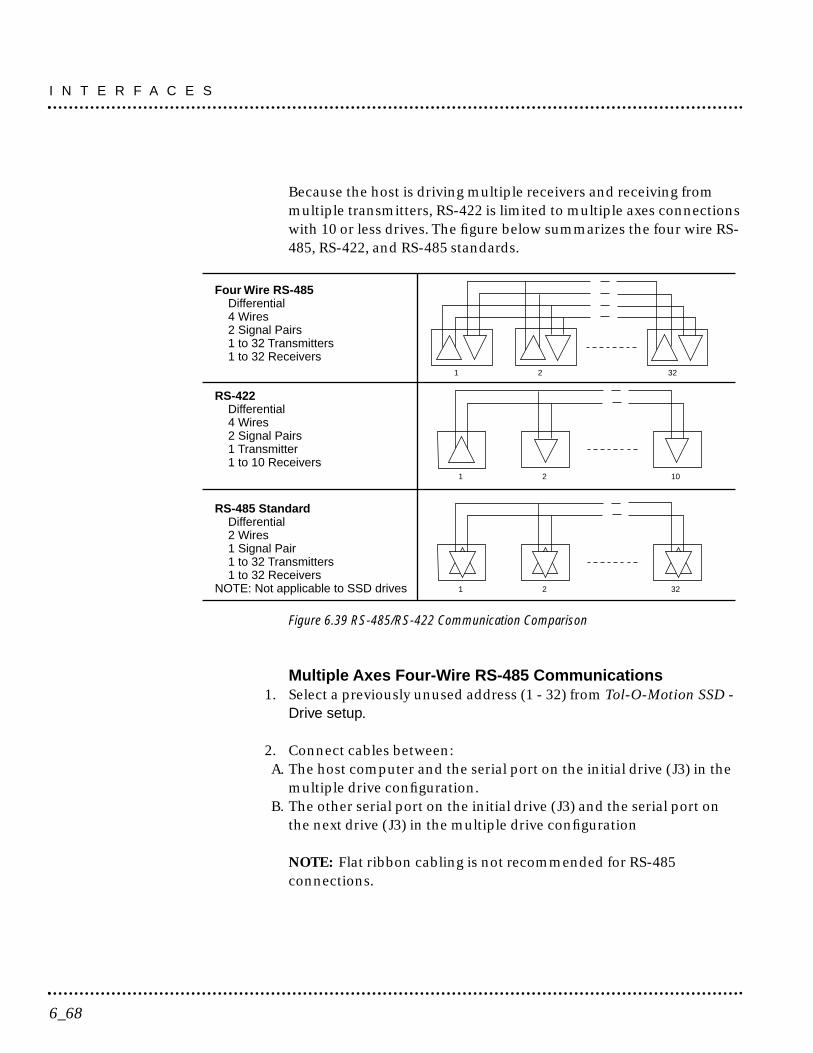
Because the host is driving multiple receivers and receiving frommultiple transmitters, RS-422 is limited to multiple axes connectionswith 10 or less drives. The figure below summarizes the four wire RS-485, RS-422, and RS-485 standards.
Figure 6.39 RS-485/RS-422 Communication Comparison
Multiple Axes Four-Wire RS-485 Communications1. Select a previously unused address (1 - 32) from Tol-O-Motion SSD -
Drive setup.
2. Connect cables between:A. The host computer and the serial port on the initial drive (J3) in the
multiple drive configuration.B. The other serial port on the initial drive (J3) and the serial port on
the next drive (J3) in the multiple drive configuration
NOTE: Flat ribbon cabling is not recommended for RS-485connections.
1 2 32
1 2 10
RS-485 Standard Differential 2 Wires 1 Signal Pair 1 to 32 Transmitters 1 to 32 ReceiversNOTE: Not applicable to SSD drives
Four Wire RS-485 Differential 4 Wires 2 Signal Pairs 1 to 32 Transmitters 1 to 32 Receivers
RS-422 Differential 4 Wires 2 Signal Pairs 1 Transmitter 1 to 10 Receivers
1 2 32
I N T E R F A C E S
6_68

3. Verify the communication settings on the computer are correct:A. Start Tol-O-Motion SSD on the attached PCB. Choose CANCEL from the Drive Select windowC. Select Communications from the menuD. Select PC setup from the pull down menu.E. Verify the port settings, and if necessary, change them, then
choose OK.
NOTE: Address 0 is the preferred address for the initial configuration ofa drive. It forces the drive to the default communications parameters.
4. Verify the ability to communicate between the computer and theconnected drives by:A. Switch drive power to ON.B. Select Communications from the menu.C. Select Read Drive Parameters from the pull down menu.D. Select the drive to communicate with from Drive Select window
(the drive must have an address that matches one of the driveaddresses in the chain).
E. Choose OK in the Drive Select window.
5. Verify that Tol-O-Motion SSD loads the drive parameters. If not, referto the troubleshooting section.
6. Repeat the preceding two steps for each additional drive.
Four-wire RS-485 connections are shown below. The cable diagramprovides a wiring example of a daisy chain connection in a typicalinstallation A multi-drop cable, as shown in Figure 6.40 may alsobe used.
6_69
I N T E R F A C E S

Multiple Axes RS-232 CommunicationsMultiple axes systems may be controlled by a computer with an RS-232serial port. An RS-232 serial communication port may be convertedto four-wire RS-485 communication by attaching an RS-232 to four-wire RS-485 converter. Figure 6.40 depicts the use of such a device.
Figure 6.40 RS-232 to RS-485 Multi-Drop Connection Diagram
PC
* Pin-outs may vary by manufacturer. This example uses a
Drive 1
RCV+RCV-XMT+J5
1 7 4 8
XMT-
COMRCV-RCV+XMT-XMT+
Drive 2
RCV+RCV-XMT+J5
1 7 4 8
XMT-
Drive n
RCV+RCV-XMT+J5
1 7 4 8
XMT-
232 to 485Adapter
7* 5*17* 3*14*
3*
2*
7*COM*
RCV*
XMT*
RS-232Interface
+12
VD
C
Ret
urn
B&B 485 Adapter
I N T E R F A C E S
6_70
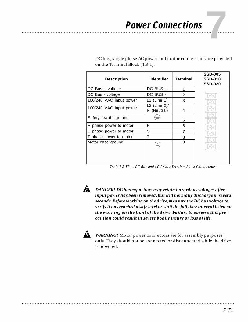
DC bus, single phase AC power and motor connections are providedon the Terminal Block (TB-1).
Table 7.A TB1 - DC Bus and AC Power Terminal Block Connections
DANGER! DC bus capacitors may retain hazardous voltages afterinput power has been removed, but will normally discharge in severalseconds. Before working on the drive, measure the DC bus voltage toverify it has reached a safe level or wait the full time interval listed onthe warning on the front of the drive. Failure to observe this pre-caution could result in severe bodily injury or loss of life.
WARNING! Motor power connectors are for assembly purposesonly. They should not be connected or disconnected while the driveis powered.
7_71
Power Connections7Description Identifier Terminal
SSD-005SSD-010SSD-020
DC Bus + voltage DC BUS + 1DC Bus - voltage DC BUS - 2100/240 VAC input power L1 (Line 1) 3
100/240 VAC input powerL2 (Line 2)/N (Neutral) 4
Safety (earth) ground5
R phase power to motor R 6S phase power to motor S 7T phase power to motor T 8Motor case ground 9
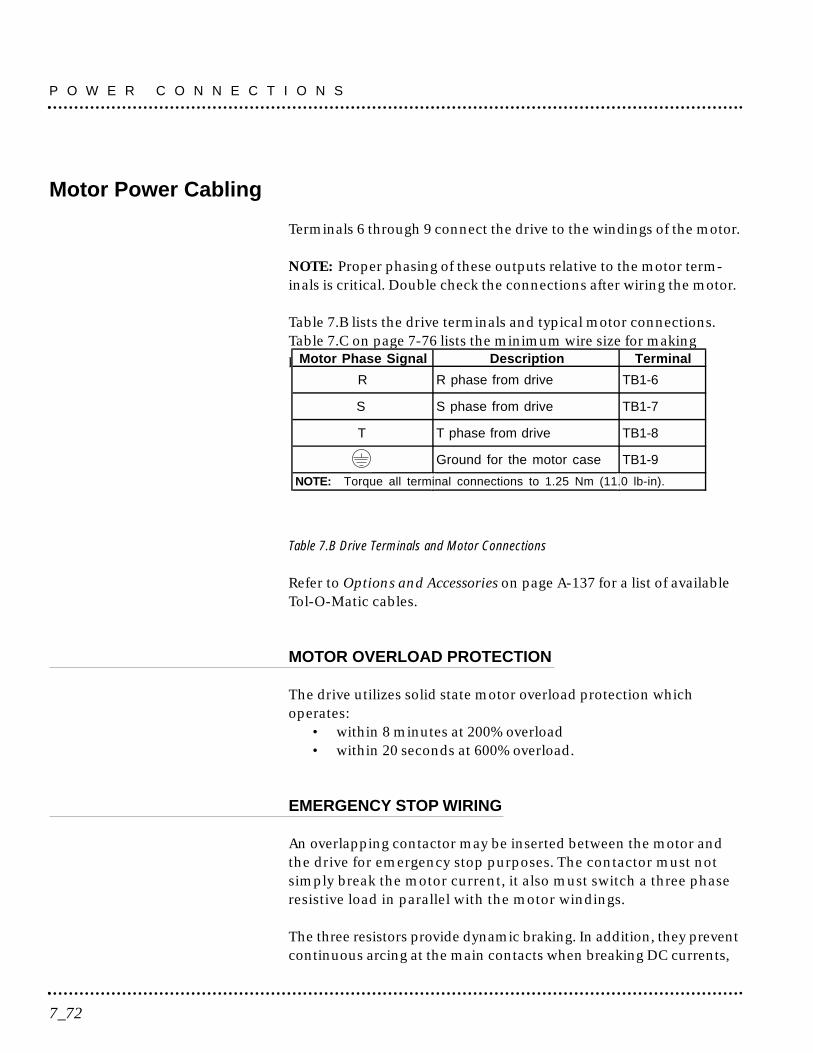
Motor Power Cabling
Terminals 6 through 9 connect the drive to the windings of the motor.
NOTE: Proper phasing of these outputs relative to the motor term-inals is critical. Double check the connections after wiring the motor.
Table 7.B lists the drive terminals and typical motor connections.Table 7.C on page 7-76 lists the minimum wire size for makingpower wiring connections.
Table 7.B Drive Terminals and Motor Connections
Refer to Options and Accessories on page A-137 for a list of availableTol-O-Matic cables.
MOTOR OVERLOAD PROTECTION
The drive utilizes solid state motor overload protection whichoperates:
• within 8 minutes at 200% overload• within 20 seconds at 600% overload.
EMERGENCY STOP WIRING
An overlapping contactor may be inserted between the motor andthe drive for emergency stop purposes. The contactor must notsimply break the motor current, it also must switch a three phaseresistive load in parallel with the motor windings.
The three resistors provide dynamic braking. In addition, they preventcontinuous arcing at the main contacts when breaking DC currents,
P O W E R C O N N E C T I O N S
7_72
Motor Phase Signal Description Terminal
R R phase from drive TB1-6
S S phase from drive TB1-7
T T phase from drive TB1-8
Ground for the motor case TB1-9
NOTE: Torque all terminal connections to 1.25 Nm (11.0 lb-in).
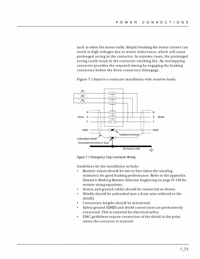
such as when the motor stalls. Simply breaking the motor current canresult in high voltages due to motor inductance, which will causeprolonged arcing in the contactor. In extreme cases, the prolongedarcing could result in the contactor catching fire. An overlappingcontactor provides the required timing by engaging the brakingcontactors before the drive contactors disengage.
Figure 7.1 depicts a contactor installation with resistive loads.
Figure 7.1 Emergency Stop Contractor Wiring
Guidelines for the installation include:• Resistor values should be one to four times the winding
resistance for good braking performance. Refer to the appendixDynamic Braking Resistor Selection beginning on page D-149 forresistor sizing equations.
• Screen and ground cables should be connected as shown.• Shields should be unbraided (not a drain wire soldered to the
shield).• Connection lengths should be minimized.• Safety ground (GND) and shield connections are permanently
connected. This is essential for electrical safety.• EMC guidelines require connection of the shield at the point
where the contactor is inserted.
R
S
T
Drive
R
S
T
Motor
GNDGND
Isolated terminal
Grounded terminal or stud
Unbraided shield
Enclosure wall
R3
R2
R1
7_73
P O W E R C O N N E C T I O N S
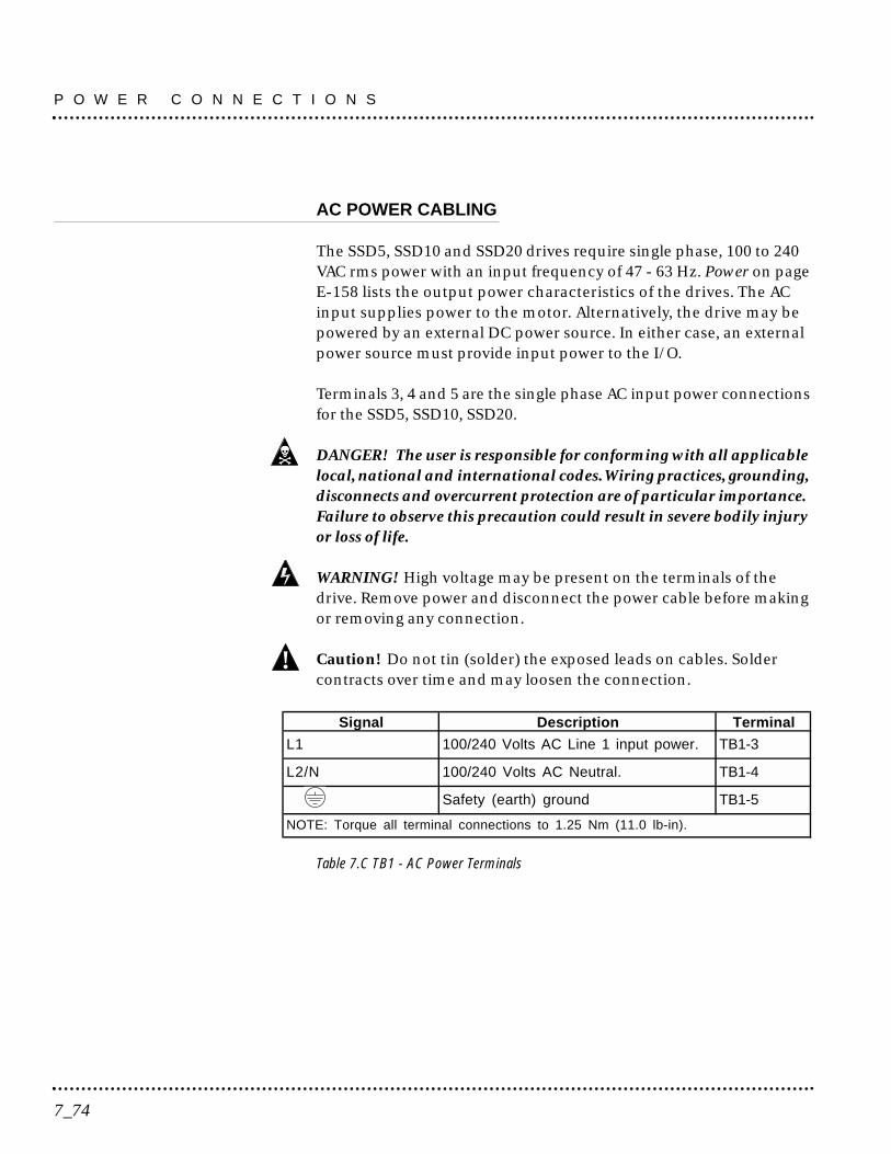
AC POWER CABLING
The SSD5, SSD10 and SSD20 drives require single phase, 100 to 240VAC rms power with an input frequency of 47 - 63 Hz. Power on pageE-158 lists the output power characteristics of the drives. The ACinput supplies power to the motor. Alternatively, the drive may bepowered by an external DC power source. In either case, an externalpower source must provide input power to the I/O.
Terminals 3, 4 and 5 are the single phase AC input power connectionsfor the SSD5, SSD10, SSD20.
DANGER! The user is responsible for conforming with all applicablelocal, national and international codes.Wiring practices, grounding,disconnects and overcurrent protection are of particular importance.Failure to observe this precaution could result in severe bodily injuryor loss of life.
WARNING! High voltage may be present on the terminals of thedrive. Remove power and disconnect the power cable before makingor removing any connection.
Caution! Do not tin (solder) the exposed leads on cables. Soldercontracts over time and may loosen the connection.
Table 7.C TB1 - AC Power Terminals
!
P O W E R C O N N E C T I O N S
7_74
Signal Description Terminal
L1 100/240 Volts AC Line 1 input power. TB1-3
L2/N 100/240 Volts AC Neutral. TB1-4
Safety (earth) ground TB1-5
NOTE: Torque all terminal connections to 1.25 Nm (11.0 lb-in).
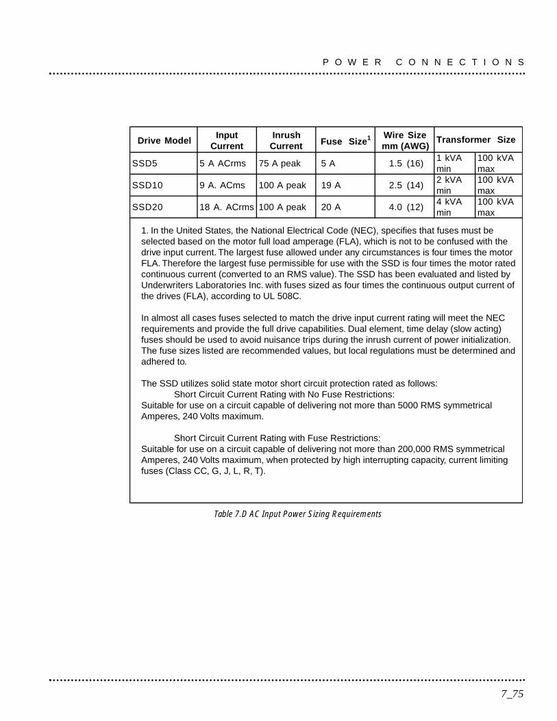
Table 7.D AC Input Power Sizing Requirements
Drive ModelInput
CurrentInrush
Current Fuse Size1 Wire Sizemm (AWG)
Transformer Size
SSD5 5 A ACrms 75 A peak 5 A 1.5 (16)1 kVAmin
100 kVAmax
SSD10 9 A. ACms 100 A peak 19 A 2.5 (14)2 kVAmin
100 kVAmax
SSD20 18 A. ACrms 100 A peak 20 A 4.0 (12)4 kVAmin
100 kVAmax
7_75
P O W E R C O N N E C T I O N S
1. In the United States, the National Electrical Code (NEC), specifies that fuses must beselected based on the motor full load amperage (FLA), which is not to be confused with thedrive input current. The largest fuse allowed under any circumstances is four times the motorFLA. Therefore the largest fuse permissible for use with the SSD is four times the motor ratedcontinuous current (converted to an RMS value). The SSD has been evaluated and listed byUnderwriters Laboratories Inc. with fuses sized as four times the continuous output current ofthe drives (FLA), according to UL 508C.
In almost all cases fuses selected to match the drive input current rating will meet the NECrequirements and provide the full drive capabilities. Dual element, time delay (slow acting)fuses should be used to avoid nuisance trips during the inrush current of power initialization.The fuse sizes listed are recommended values, but local regulations must be determined andadhered to.
The SSD utilizes solid state motor short circuit protection rated as follows:Short Circuit Current Rating with No Fuse Restrictions:
Suitable for use on a circuit capable of delivering not more than 5000 RMS symmetricalAmperes, 240 Volts maximum.
Short Circuit Current Rating with Fuse Restrictions:Suitable for use on a circuit capable of delivering not more than 200,000 RMS symmetricalAmperes, 240 Volts maximum, when protected by high interrupting capacity, current limitingfuses (Class CC, G, J, L, R, T).

P O W E R C O N N E C T I O N S
7_76
This chapter provides information on how to install and verify theSSD drive for various modes of operation. The procedures verify theinstallation by:
• Showing how the power and logic wiring is connected.• Selecting the operational mode (Velocity or Torque) for the drive
using a specified analog input signal type.• Tuning the drive for a particular motor type and size.• Verifying the basic functionality of the drive and motor
combination.
Analog Control
If a Tol-O-Matic SSC Controller is being used, the drive will be pre-configured to run using Analog Control at the factory. No additionaladjustments should be necessary. (Please consult the SSC Controllermanual.)
To setup the unit as an Analog drive in either the Velocity or Torquemode, make the connections described below. Figure 8.1 depicts theminimum hardware necessary. Interfacing the drive to a controllerrequires similar output circuitry from the controller to J1. Instructionsare provided to configure the drive with Tol-O-Motion SSD software.
HARDWARE SETUP
Make the connections described below and shown in Figure 8.1.
1. Connect a ±10VDC power source as shown to provide the analogspeed or torque command.
2. Connect an RS-232 cable between the serial port on the PC and theJ3 connector on the drive, or connect a TouchPad to the J3 connector.
3. Connect a Motor/Feedback cable from the motor to the J2 connectoron the drive.
4. Connect a Power cable from the motor to TB1 (terminals R, S, T and) on the drive.
8_77
Applications and Configuration Examples 8
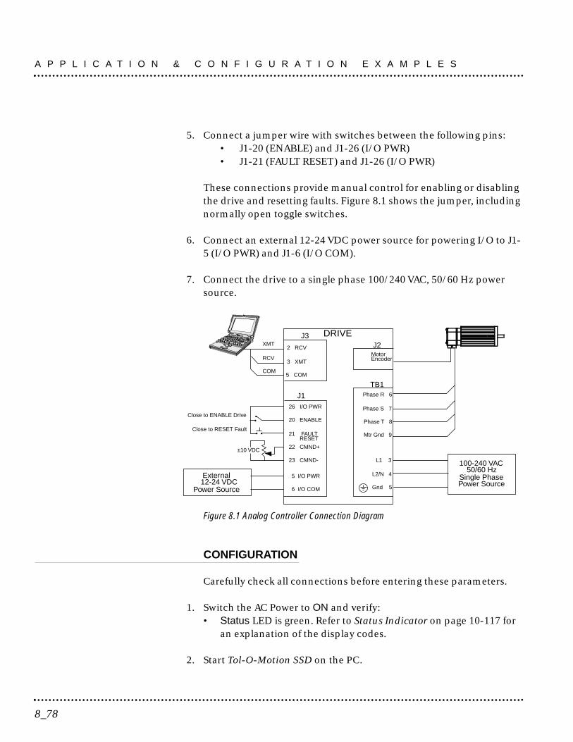
5. Connect a jumper wire with switches between the following pins:• J1-20 (ENABLE) and J1-26 (I/O PWR)• J1-21 (FAULT RESET) and J1-26 (I/O PWR)
These connections provide manual control for enabling or disablingthe drive and resetting faults. Figure 8.1 shows the jumper, includingnormally open toggle switches.
6. Connect an external 12-24 VDC power source for powering I/O to J1-5 (I/O PWR) and J1-6 (I/O COM).
7. Connect the drive to a single phase 100/240 VAC, 50/60 Hz powersource.
Figure 8.1 Analog Controller Connection Diagram
CONFIGURATION
Carefully check all connections before entering these parameters.
1. Switch the AC Power to ON and verify:• Status LED is green. Refer to Status Indicator on page 10-117 for
an explanation of the display codes.
2. Start Tol-O-Motion SSD on the PC.
J126 I/O PWR
20 ENABLE
21 FAULT
22 CMND+
23 CMND-
Close to ENABLE Drive
Close to RESET Fault
±10 VDC
DRIVE
L1 3
L2/N 4
Gnd 5
100-240 VAC50/60 Hz
Single PhasePower Source
RESET
J3
2 RCV
3 XMT
5 COM
XMT
RCV
COM
TB1Phase R 6
Phase S 7
Phase T 8
Mtr Gnd 9
J2MotorEncoder
External12-24 VDC
Power Source
5 I/O PWR
6 I/O COM
A P P L I C A T I O N & C O N F I G U R A T I O N E X A M P L E S
8_78

3. Choose Cancel from the Drive Select dialog box.
4. Select PC setup from the Communications menu in Tol-O-MotionSSD to display the personal computer’s communication settings.
5. Verify the communication port settings of the PC match those of thedrive. Factory default drive settings are:
• Baud Rate: 9600• Data Bits: 8• Parity: None• Stop Bits: 1• Serial Port: COM1
Select OK in the Port - Settings dialog box when the settings arecorrect.
6. Select Read Drive Parameters from the Communications menu.
7. Verify the Drive Name and Address are correct for the drive that isbeing addressed.
8. Choose OK to load the drive parameters.
NOTE: A motor must be selected for the parameters to load.
9. If the message box appears that a motor must be selected, select OK.The Drive Setup window is displayed with Motor Model selectionparameter active. The motor may be selected from the drop downbox. If this message box does not appear, the motor displayed in theMotor Model box was previously selected.
10. Select or verify the correct motor model number from the dropdown Motor Model list.
11. Choose OK, if a message advises that the drive must be reset. Achange in motor parameters requires reselection of the firmwarebased drive/motor tables. The software reset is required to preventimproper sequencing of these table parameters.
8_79
A P P L I C A T I O N & C O N F I G U R A T I O N E X A M P L E S
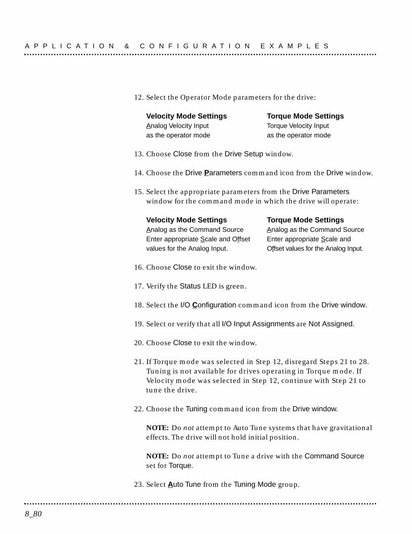
12. Select the Operator Mode parameters for the drive:
Velocity Mode Settings Torque Mode SettingsAnalog Velocity Input Torque Velocity Inputas the operator mode as the operator mode
13. Choose Close from the Drive Setup window.
14. Choose the Drive Parameters command icon from the Drive window.
15. Select the appropriate parameters from the Drive Parameterswindow for the command mode in which the drive will operate:
Velocity Mode Settings Torque Mode SettingsAnalog as the Command Source Analog as the Command SourceEnter appropriate Scale and Offset Enter appropriate Scale and values for the Analog Input. Offset values for the Analog Input.
16. Choose Close to exit the window.
17. Verify the Status LED is green.
18. Select the I/O Configuration command icon from the Drive window.
19. Select or verify that all I/O Input Assignments are Not Assigned.
20. Choose Close to exit the window.
21. If Torque mode was selected in Step 12, disregard Steps 21 to 28.Tuning is not available for drives operating in Torque mode. IfVelocity mode was selected in Step 12, continue with Step 21 totune the drive.
22. Choose the Tuning command icon from the Drive window.
NOTE: Do not attempt to Auto Tune systems that have gravitationaleffects. The drive will not hold initial position.
NOTE: Do not attempt to Tune a drive with the Command Sourceset for Torque.
23. Select Auto Tune from the Tuning Mode group.
A P P L I C A T I O N & C O N F I G U R A T I O N E X A M P L E S
8_80
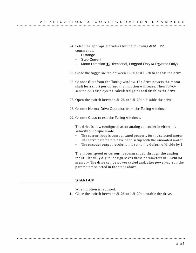
24. Select the appropriate values for the following Auto Tunecommands.• Distance• Step Current• Motor Direction (BiDirectional, Forward Only or Reverse Only)
25. Close the toggle switch between J1-26 and J1-20 to enable the drive.
26. Choose Start from the Tuning window. The drive powers the motorshaft for a short period and then motion will cease. Then Tol-O-Motion SSD displays the calculated gains and disables the drive.
27. Open the switch between J1-26 and J1-20 to disable the drive.
28. Choose Normal Drive Operation from the Tuning window.
29. Choose Close to exit the Tuning windows.
The drive is now configured as an analog controller in either theVelocity or Torque mode.• The current loop is compensated properly for the selected motor. • The servo parameters have been setup with the unloaded motor. • The encoder output resolution is set to the default of divide by 1.
The motor speed or current is commanded through the analoginput. The fully digital design saves these parameters in EEPROMmemory. The drive can be power cycled and, after power-up, run theparameters selected in the steps above.
START-UP
When motion is required. 1. Close the switch between J1-26 and J1-20 to enable the drive.
8_81
A P P L I C A T I O N & C O N F I G U R A T I O N E X A M P L E S

Preset Controller
To setup the unit as a Preset drive in the Velocity or Torque mode,make the connections described below. The following table shows thethree discrete digital inputs A, B, C that select the programmablespeed or torque control. Up to eight different preset speed ortorque settings can be selected by using the three digital inputs invarious binary combinations. Figure 8.2 depicts the minimumhardware necessary. Interfacing the drive to a controller requiressimilar output circuitry from the controller to J1. Instructions areprovided to configure the drive with Tol-O-Matic software. Wiredinputs 1,2,3 can be software configured as A, B or C.
Table 8.A Preset Binary Velocity or Torque Inputs
HARDWARE SETUP
Make the connections described below and shown in Figure 8.2.
1. Connect an RS-232 cable between the serial port on the PC and the J3connector on the drive. • Options and Accessories on page A-137 lists cables available from
Tol-O-Matic. Cable Diagrams, Schematics and Examples on pageB-139 show cable schematics.
InputsC B A Description
Preset 0 0 0 0 Preset 0 is a preprogrammed speed or current. Allinputs are OFF1.
Preset 1 0 0 1 Preset 1 is a preprogrammed speed or current. OnlyPreset Select A input is ON.
Preset 2 0 1 0 Preset 2 is a preprogrammed speed or current. OnlyPreset Select B input is ON.
Preset 3 0 1 1 Preset 3 is a preprogrammed speed or current. PresetSelect A and Preset Select B are ON 2.
Preset 4 1 0 0 Preset 4 is a preprogrammed speed or current. OnlyPreset Select C input is ON2.
Preset 5 1 0 1 Preset 5 is a preprogrammed speed or current. PresetSelect A and Preset Select C are active ON 2.
Preset 6 1 1 0 Preset 6 is a preprogrammed speed or current. PresetSelect B and Preset Select C are active ON 2.
Preset 7 1 1 1 Preset 7 is a preprogrammed speed or current. AllPreset Select inputs are ON2.
1A preset input signal that is OFF is inactive, which means no current flows through the optocoupler. 2A preset input signal that is ON is active, which means current flows through the optocoupler.
A P P L I C A T I O N & C O N F I G U R A T I O N E X A M P L E S
8_82
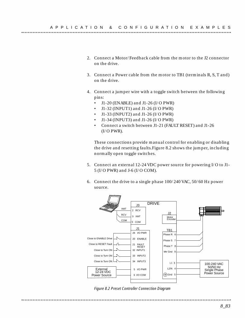
2. Connect a Motor/Feedback cable from the motor to the J2 connectoron the drive.
3. Connect a Power cable from the motor to TB1 (terminals R, S, T and)on the drive.
4. Connect a jumper wire with a toggle switch between the followingpins:• J1-20 (ENABLE) and J1-26 (I/O PWR)• J1-32 (INPUT1) and J1-26 (I/O PWR)• J1-33 (INPUT2) and J1-26 (I/O PWR)• J1-34 (INPUT3) and J1-26 (I/O PWR)• Connect a switch between J1-21 (FAULT RESET) and J1-26
(I/O PWR).
These connections provide manual control for enabling or disablingthe drive and resetting faults.Figure 8.2 shows the jumper, includingnormally open toggle switches.
5. Connect an external 12-24 VDC power source for powering I/O to J1-5 (I/O PWR) and J-6 (I/O COM).
6. Connect the drive to a single phase 100/240 VAC, 50/60 Hz powersource.
Figure 8.2 Preset Controller Connection Diagram
J126 I/O PWR
20 ENABLE
21 FAULT
32 INPUT1
33 INPUT2
Close to ENABLE Drive
Close to RESET Fault
34 INPUT3
Close to Turn ON
Close to Turn ON
Close to Turn ON
DRIVE
L1 3
L2/N 4
Gnd 5
100-240 VAC50/50 Hz
Single PhasePower Source
J3
2 RCV
3 XMT
5 COM
XMT
RCV
COM
RESET
TB1Phase R 6
Phase S 7
Phase T 8
Mtr Gnd 9
J2MotorEncoder
External12-24 VDC
Power Source
5 I/O PWR
6 I/O COM
8_83
A P P L I C A T I O N & C O N F I G U R A T I O N E X A M P L E S

CONFIGURATION
Carefully check all connections before entering these parameters.
1. Switch the AC Power to ON and verify:
• Status LED is green. Refer to Status Indicator on page 10-117 foran explanation of the display codes.
2. Start Tol-O-Motion SSD on the PC.
3. Choose Cancel from the Drive Select dialog box.
4. Select PC setup from the Communications menu in Tol-O-MotionSSD to display the personal computer’s communication settings.
5. Verify the communication port settings of the PC match those of thedrive. Factory default drive settings are:
• Baud Rate: 9600• Data Bits: 8• Parity: None• Stop Bits: 1• Serial Port: COM1
Select OK in the Port - Settings dialog box when the settings are correct.
6. Select Read Drive Parameters from the Communications menu.
7. Verify the Drive Name and Address are correct for the drive that isbeing addressed.
8. Choose OK to load the drive parameters. NOTE: A motor must beselected for the parameters to load.
9. If the message box appears that a motor must be selected, select OK.The Drive Setup window is displayed with Motor Model selectionparameter active. The motor may be selected from the drop downbox. If this message box does not appear, the motor displayed in theMotor Model box was previously selected.
A P P L I C A T I O N & C O N F I G U R A T I O N E X A M P L E S
8_84
10. Select or verify the correct motor model number from the dropdown Motor Model list.
11. Choose OK, if a message advises that the drive must be reset. Achange in motor parameters requires reselection of the firmwarebased drive/motor tables. The software reset is required to preventimproper sequencing of these table parameters.
12. Select the Operator Mode parameters for the drive:
Velocity Mode Settings Torque Mode SettingsPreset Velocities Preset Torques as the operator mode as the operator mode
13. Choose Close from the Drive Setup window.
14. Choose the Drive Parameters command icon from the Drive window.
15. Select the appropriate parameters from the Drive Parameterswindow for the command mode in which the drive will operate:
Velocity Mode Settings Torque Mode SettingsPresets as the Command Source Presets as the Command SourceEnter appropriate speed(s) Enter appropriate torque(s)for the application for the application
16. Choose Close to exit the window.
17. Verify the Status LED is green.
18. Select Close to exit the dialog box.
19. Select the I/O Configuration command icon from the Drive window.
Assign a digital input to each of the three Preset Selects (A, B and C):For example, the following selects three presets:
• Input 1 to Preset Select A• Input 2 to Preset Select B• Input 3 to Preset Select C
8_85
A P P L I C A T I O N & C O N F I G U R A T I O N E X A M P L E S

The three presets provide up to eight binary combinations of speedor current. Not assigned preset inputs are forced to an OFF state. Refer to Table 8.A.
20. Choose Close to exit the window.
21. If Torque mode was selected in Step 14, disregard Steps 21 to 28.Tuning is not available for drives operating in Torque mode. IfVelocity mode was selected in Step 14, continue with Step 21 to tunethe drive.
22. Choose the Tuning command icon from the Drive window.
NOTE: Do not attempt to Auto Tune systems that have gravitationaleffects. The drive will not hold initial position.
NOTE: Do not attempt to Tune a drive with the Command Sourceset for Torque.
23. Verify the Status LED is green.
24. Select Auto Tune from the Tuning Mode group.
25. Select the appropriate values for the following Auto Tune commands.• Distance• Step Current• Motor Direction (BiDirectional, Forward Only or Reverse Only)
26. Close the toggle switch between J1-26 and J1-20 to enable the drive.
27. Choose Start from the Tuning window. The drive powers the motorshaft for a short period and then motion will cease. Then Tol-O-Motion SSD displays the calculated gains and disables the drive.
28. Choose Normal Drive Operation from the Tuning window.
29. Open the switch between J1-26 and J1-20 to disable the drive.
30. Choose Close to exit the Tuning window.
31. Verify the Status LED is green.
A P P L I C A T I O N & C O N F I G U R A T I O N E X A M P L E S
8_86
32. Close any open windows or dialog boxes.
The drive is now configured as either a preset controller in theVelocity or Torque mode.
• The current loop is compensated properly for the selected motor. • The servo parameters have been setup with the unloaded motor. • The encoder output resolution is set to the default of divide by 1.
The motor speed or current is controlled through the digital inputs.The fully digital design saves the parameters in EEPROM memory.Thus the drive can be power cycled and, after power-up, run theparameters set in the steps above.
START-UP
When motion is required:
1. Close the switch between J1-26 and J1-20 to enable the drive.
2. Close any of the switches for INPUT1, INPUT2 or INPUT3 to run thedrive at the programmed preset speed or torque.
Position Follower (Master Encoder)
The drive can be electronically geared to a master incremental encodergenerating quadrature encoder signals. Make the connections below tosetup the drive as a position follower. Figure 8.3 depicts the minimumhardware necessary. Interfacing the drive to a controller requiressimilar output circuitry from the controller to J1. Instructions areprovided to configure the drive with Tol-O-Motion SSD software.
NOTE: If the SSD is enabled without defining one of the DigitalInputs as Follower Enable, Tol-O-Motion SSD automaticallyconfigures the SSD as the follower.
8_87
A P P L I C A T I O N & C O N F I G U R A T I O N E X A M P L E S
HARDWARE SETUP
Make the connections described below and shown in Figure 8.3.
1. Connect an RS-232 cable between the serial port on the PC and theJ3 connector on the drive.
• Options and Accessories on page E-137 lists cables available fromTol-O-Matic. Cable Diagrams, Schematics and Examples on pageB-139 shows cable schematics.
2. Connect a Motor/Feedback cable from the motor to the J2 connectoron the drive.
3. Connect a Power cable from the motor to TB1 (terminals R, S, T andGND) on the drive.
4. Connect the Master Encoder to the drive as shown in the diagram.
5. Connect a jumper wire with a switch between each of the followingpins:
• J1-20 (ENABLE) and J1-26 (I/O PWR)• J1-32 (INPUT1) and J1-26 (I/O PWR)• J1-21 (FAULT RESET) and J1-26 (I/O PWR).
These connections provide manual control for enabling or disablingthe drive and resetting faults. Figure 8.3 shows the jumper, includingnormally open toggle switches.
6. Connect an external 12-24 VDC power source for powering I/O to J1-5 (I/O PWR) and J-6 (I/O COM).
7. Connect the drive to a single phase 100/240 VAC, 50/60 Hz powersource.
A P P L I C A T I O N & C O N F I G U R A T I O N E X A M P L E S
8_88

Figure 8.3 Position Follower (Master Encoder) Connection Diagram
CONFIGURATION
Carefully check all connections before entering these parameters.
1. Switch the AC power to ON and verify:• Status LED is green. Refer to Status Indicator on page 10-117 for
an explanation of the display codes.
2. Start Tol-O-Motion SSD on the PC.
3. Choose Cancel from the Drive Select dialog box.
4. Select PC setup from the Communications menu in Tol-O-MotionSSD to display the personal computer’s communication settings.
J11 +5V1
2 5V COM
MasterEncoder
14 AX+
15 AX-
16 BX+
Close to ENABLE Drive
Close to RESET Fault
17 BX-
18 IX+
19 IX-
20 ENABLE
21 FAULT RESET
Close to Turn ON
DRIVE
L1 3
L2/N 4
Gnd 5
100-240 VAC50/50 Hz
Single PhasePower Source
J3
2 RCV
3 XMT
5 COM
XMT
RCV
COM
TB1Phase R 6
Phase S 7
Phase T 8
Mtr Gnd 9
J2MotorEncoder
External+24 VDC
Power Source
5 +24VDC
6 24VCOM
26 +24V
32 INPUT1
8_89
A P P L I C A T I O N & C O N F I G U R A T I O N E X A M P L E S

5. Verify the communication port settings of the PC match those of thedrive. Factory default drive settings are:• Baud Rate: 9600• Data Bits: 8• Parity: None• Stop Bits: 1• Serial Port: COM1• Select OK in the Port - Settings dialog box when the settings are
correct.
6. Select Read Drive Parameters from the Communications menu.
7. Verify the Drive Name and Address are correct for the drive that isbeing addressed.
8. Choose OK to load the drive parameters.
NOTE: A motor must be selected for the parameters to load.
9. If the message box appears that a motor must be selected, select OK.The Drive Setup window is displayed with Motor Model selectionparameter active. The motor may be selected from the drop downbox. If this message box does not appear, the motor displayed in theMotor Model box was previously selected.
10. Select or verify the correct motor model number from the dropdown Motor Model list.
11. Choose OK, if a message advises that the drive must be reset. Achange in motor parameters requires reselection of the firmwarebased drive/motor tables. The software reset is required to preventimproper sequencing of these table parameters.
12. Choose Close from the Drive Setup window.
13. Choose the Drive Parameters command icon from the Drive window.
A P P L I C A T I O N & C O N F I G U R A T I O N E X A M P L E S
8_90

14. Select the appropriate parameters from the Drive Parameterswindow for the command mode in which the drive will operate:
Master Encoder as the Command Source
Velocity as the Mode
Enter an appropriate Gear Ratio as the Follower Input.
15. Choose Close to exit the window.
16. Verify the Status LED is green.
17. Select the I/O Configuration command icon from the Drive Window.
18. Select an appropriate digital input from the pull-down lists availableas Digital Input Assignments in the I/O Configuration window.
For example: • Follower Enable as Input 1• Not Assigned as Inputs 2 through 3.
19. Choose Close to exit the window.
20. Choose the Tuning command icon from the Drive window.
NOTE: Do not attempt to Auto Tune systems that have gravitationaleffects. The drive will not hold initial position.
NOTE: Do not attempt to Tune a drive with the Command Sourceset for Torque.
21. Verify the Status LED is green.
22. Select AutoTune from the Tuning Mode group.
23. Select the appropriate values for the following Auto Tune commands.• Distance• Step Current• Motor Direction (BiDirectional, Forward Only or Reverse Only)
8_91
A P P L I C A T I O N & C O N F I G U R A T I O N E X A M P L E S
24. Close the toggle switch between J1-26 and J1-20 to enable the drive.
25. Choose Start from the Tuning window. The drive powers the motorshaft for a short period and then motion will cease. Then Tol-O-Motion SSD displays the calculated gains and disables the drive.
26. Choose Normal Drive Operation from the Tuning window.
27. Open the switch between J1-26 and J1-20 to disable the drive.
28. Choose Close to exit the Tuning window.
29. Verify the Status LED is green.
30. Close any open windows or dialog boxes.
The drive is now configured as a Position Follower. • The current loop is compensated properly for the selected motor. • The servo parameters have been setup with the unloaded motor. • The encoder output resolution is set to the default of divide by 1.
The motor speed and position is controlled by the master encoderinput. The fully digital design saves the parameters in EEPROMmemory. Thus the controller can be power cycled and, after power-up, run the parameters set in the steps above.
START-UP
When motion is required:
1. Close the switch between J1-26 and J1-20 to enable the drive.
2. Close the switch between J1-26 and J1-32 to enable the followermode.
A P P L I C A T I O N & C O N F I G U R A T I O N E X A M P L E S
8_92

Position Follower (Step/Direction)
If a Tol-O-Matic MSC Controller is to be used, the SSD drive will bepre-configured for step/direction control at the factory. No additionaladjustments should be necessary. (Please consult the Tol-O-MaticMSC manual.)
The drive can be electronically geared or driven by Step and Directionsignals typically used to control stepper drives. Make the connectionsbelow to setup the drive as a Position Follower in Velocity mode.Figure 8.4 depicts the minimum hardware necessary. Interfacing thedrive to a controller requires similar output circuitry from thecontroller to J1. Instructions are provided to configure the drive withTol-O-Motion SSD software.
NOTE: If the SSD is enabled without defining one of the DigitalInputs as Follower Enable, Tol-O-Motion SSD automaticallyconfigures the SSD as the follower.
HARDWARE SETUP
Make the connections described below and shown in Figure 8.4.
1. Connect an RS-232 cable between the serial port on the PC and theJ3 connector on the drive.
2. Connect a Motor/Feedback cable from the motor to the J2 connectoron the drive.
3. Connect a Power cable from the motor to TB1 (terminals R, S, T and) on the drive.
4. Connect the Stepper Indexer to the drive as shown in Figure 8.4.Themotor is controlled by the indexer commands.
5. Connect a jumper wire with switches between the following pins:• J1-20 (ENABLE) and J1-26 (I/O PWR) • J1-32 (INPUT 1) and J1-26 (I/O PWR) • J1-21 (FAULT RESET) and J1-26 (I/O PWR).
8_93
A P P L I C A T I O N & C O N F I G U R A T I O N E X A M P L E S
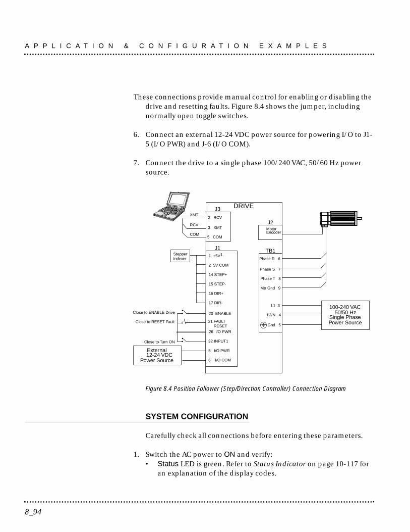
These connections provide manual control for enabling or disabling thedrive and resetting faults. Figure 8.4 shows the jumper, includingnormally open toggle switches.
6. Connect an external 12-24 VDC power source for powering I/O to J1-5 (I/O PWR) and J-6 (I/O COM).
7. Connect the drive to a single phase 100/240 VAC, 50/60 Hz powersource.
Figure 8.4 Position Follower (Step/Direction Controller) Connection Diagram
SYSTEM CONFIGURATION
Carefully check all connections before entering these parameters.
1. Switch the AC power to ON and verify:• Status LED is green. Refer to Status Indicator on page 10-117 for
an explanation of the display codes.
J11 +5V1Stepper
Indexer
2 5V COM
14 STEP+
15 STEP-
16 DIR+
Close to ENABLE Drive
Close to RESET Fault
17 DIR-
20 ENABLE
21 FAULT RESET
Close to Turn ON
DRIVE
L1 3
L2/N 4
Gnd 5
100-240 VAC50/50 Hz
Single PhasePower Source
J3
2 RCV
3 XMT
5 COM
XMT
RCV
COM
TB1Phase R 6
Phase S 7
Phase T 8
Mtr Gnd 9
J2MotorEncoder
External12-24 VDC
Power Source
5 I/O PWR
6 I/O COM
26 I/O PWR
32 INPUT1
A P P L I C A T I O N & C O N F I G U R A T I O N E X A M P L E S
8_94
2. Start Tol-O-Motion SSD on the PC.
3. Choose Cancel from the Drive Select dialog box.
4. Select PC setup from the Communications menu in Tol-O-MotionSSD to display the personal computer’s communication settings.
5. Verify the communication port settings of the PC match those of thedrive. Factory default drive settings are:
• Baud Rate: 9600• Data Bits: 8• Parity: None• Stop Bits: 1• Serial Port: COM1
6. Select OK in the Port - Settings dialog box when the settings are correct.
7. Select Read Drive Parameters from the Communications menu.
8. Verify the Drive Name and Address are correct for the drive that isbeing addressed.
9. Choose OK to load the drive parameters. NOTE: A motor must beselected for the parameters to load.
10. If the message box appears that a motor must be selected, select OK.The Drive Setup window is displayed with Motor Model selectionparameter active. The motor may be selected from the drop downbox. If this message box does not appear, the motor displayed in theMotor Model box was previously selected.
11. Select or verify the correct motor model number from the dropdown Motor Model list.
12. Choose OK, if a message advises that the drive must be reset. Achange in motor parameters requires reselection of the firmwarebased drive/motor tables. The software reset is required to preventimproper sequencing of these table parameters.
13. Choose Close from the Drive Setup window.
8_95
A P P L I C A T I O N & C O N F I G U R A T I O N E X A M P L E S

14. Choose the Drive Parameters command icon from the Drive window.
15. Select the appropriate parameters from the Drive Parameterswindow for the drive:
Step/Direction as the Command SourceVelocity as the ModeEnter the appropriate Gear Ratio as the Follower Input.
16. Choose Close to exit the window.
17. Verify the Status LED is green.
18. Choose the I/O Configuration command icon from the Drive window.
19. Select an appropriate digital input from the pull-down lists availableas Digital Input Assignments in the I/O Configuration window.
For example:• Follower Enable as Input 1.• Not Assigned as Inputs 2 through 3.
20. Choose Close to exit the window.
21. Choose the Tuning command icon from the Drive window.
NOTE: Do not attempt to AutoTune systems that have gravitationaleffects. The drive will not hold initial position.
NOTE: Do not attempt to Tune a drive with the Command Sourceset for Torque.
22. Select Auto Tune from the Tuning Mode group.
23. Select the appropriate values for the following Auto Tune commands.• Distance• Step Current• Motor Direction (BiDirectional, Forward Only or Reverse Only)
24. Close the toggle switch between J1-26 and J1-20 to enable the drive.
A P P L I C A T I O N & C O N F I G U R A T I O N E X A M P L E S
8_96

25. Choose Start from the Tuning window. The drive powers the motorshaft for a short period and then motion will cease. Then the calculatedgains are displayed and the drive is disabled.
26. Choose Normal Drive Operation from the Tuning window.
27. Open the switch between J1-26 and J1-20 to disable the drive.
28. Choose Close to exit the Tuning window.
29. Verify the Status LED is green.
30. Close any open windows or dialog boxes.
The drive is now configured as a position follower (step/direction). • The current loop is compensated properly for the selected motor. • The servo parameters have been setup with the unloaded motor. • The encoder output resolution is set to the default of divide by 1.
The motor position is commanded by the stepper indexer. The fullydigital design saves the parameters in EEPROM memory. Thus thedrive can be power cycled and, after power-up, run the parametersset in the steps above.
START-UP
When motion is required:
1. Close the switch between J1-26 and J1-20 to enable the drive.
2. Close the toggle switch between J1-26 and J1-32 to enable thefollower mode.
8_97
A P P L I C A T I O N & C O N F I G U R A T I O N E X A M P L E S

Position Follower (Step Up/Step Down)
The drive can be electronically geared or driven by Step Up and StepDown signals typically used to control stepper drives. Make theconnections below to setup the drive as a position follower. Figure8.5 depicts the minimum hardware necessary. Interfacing thedrive to a controller requires similar output circuitry from thecontroller to J1. Instructions are provided to configure the drive withTol-O-Motion SSD software.
NOTE: If the SSD is enabled without defining one of the DigitalInputs as Follower Enable, Tol-O-Motion SSD automaticallyconfigures the SSD as the follower.
HARDWARE SETUP
Make the connections described below and shown in Figure 8.5.
1. Connect an RS-232 cable between the serial port on the PC and the J4connector on the drive, or connect a TouchPad to the J3 connector.
2. Connect a Motor/Feedback cable from the motor to the J2 connectoron the drive.
3. Connect a Power cable from the motor to TB1 (terminals R, S, T and) on the drive.
4. Connect the Stepper Indexer to the drive as shown in Figure 8.5. Themotor is controlled by the indexer commands.
5. Connect a jumper wire with switches between the following pins:• J1-20 (ENABLE) and J1-26 (I/O PWR) • J1-32 (INPUT1) and J1-26 (I/O PWR)• J1-21 (FAULT RESET) and J1-26 (I/O PWR).
These connections provide manual control for enabling or disablingthe drive and resetting faults. Figure 8.5 shows the jumper, includingnormally open toggle switches.
A P P L I C A T I O N & C O N F I G U R A T I O N E X A M P L E S
8_98
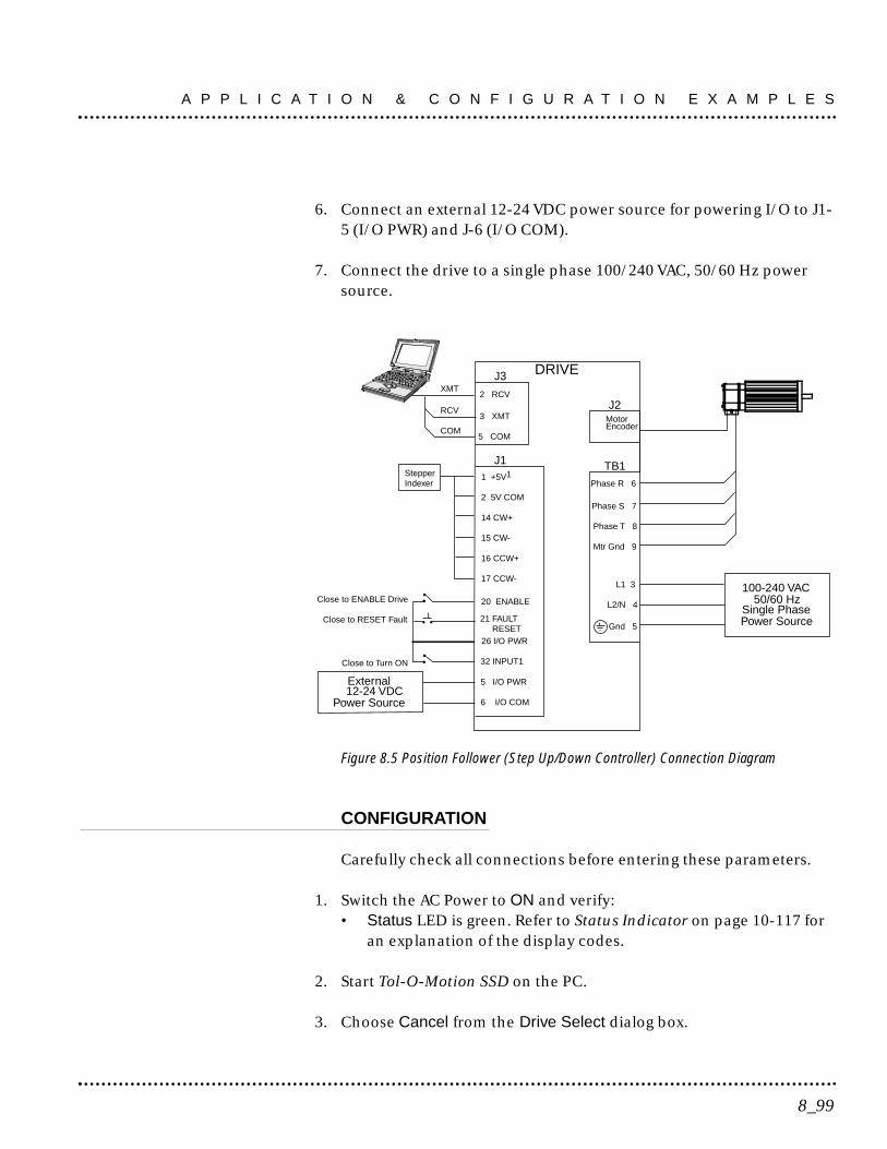
6. Connect an external 12-24 VDC power source for powering I/O to J1-5 (I/O PWR) and J-6 (I/O COM).
7. Connect the drive to a single phase 100/240 VAC, 50/60 Hz powersource.
Figure 8.5 Position Follower (Step Up/Down Controller) Connection Diagram
CONFIGURATION
Carefully check all connections before entering these parameters.
1. Switch the AC Power to ON and verify:• Status LED is green. Refer to Status Indicator on page 10-117 for
an explanation of the display codes.
2. Start Tol-O-Motion SSD on the PC.
3. Choose Cancel from the Drive Select dialog box.
J11 +5V1Stepper
Indexer
2 5V COM
14 CW+
15 CW-
16 CCW+
Close to ENABLE Drive
Close to RESET Fault
17 CCW-
20 ENABLE
21 FAULT RESET
Close to Turn ON
DRIVE
L1 3
L2/N 4
Gnd 5
100-240 VAC50/60 Hz
Single PhasePower Source
J3
2 RCV
3 XMT
5 COM
XMT
RCV
COM
TB1Phase R 6
Phase S 7
Phase T 8
Mtr Gnd 9
J2MotorEncoder
External12-24 VDC
Power Source
5 I/O PWR
6 I/O COM
26 I/O PWR
32 INPUT1
8_99
A P P L I C A T I O N & C O N F I G U R A T I O N E X A M P L E S

4. Select PC setup from the Communications menu in Tol-O-MotionSSD to display the personal computer’s communication settings.
5. Verify the communication port settings of the PC match those of thedrive. Factory default drive settings are:
• Baud Rate: 9600• Data Bits: 8• Parity: None• Stop Bits: 1• Serial Port: COM1
6. Select OK in the Port - Settings dialog box when the settings arecorrect.
7. Select Read Drive Parameters from the Communications menu.
8. Verify the Drive Name and Address are correct for the drive that isbeing addressed.
9. Choose OK to load the drive parameters. NOTE: A motor must beselected for the parameters to load.
10. If the message box appears that a motor must be selected, select OK.The Drive Setup window is displayed with Motor Model selectionparameter active. The motor may be selected from the drop downbox. If this message box does not appear, the motor displayed in theMotor Model box was previously selected.
11. Select or verify the correct motor model number from the drop downMotor Model list.
12. Choose OK, if a message advises that the drive must be reset. Achange in motor parameters requires reselection of the firmwarebased drive/motor tables. The software reset is required to preventimproper sequencing of these table parameters.
13. Choose Close from the Drive Setup window.
14. Choose the Drive Parameters command icon from the Drive window.
A P P L I C A T I O N & C O N F I G U R A T I O N E X A M P L E S
8_100
15. Select the appropriate parameters from the Drive Parameters windowfor the drive:
Step Up/Step Down as the Command SourceVelocity as the ModeEnter the appropriate Gear Ratio as the Follower Input.
16. Choose Close to exit the window.
17. Verify the Status LED is green.
18. Select the I/O Configuration command icon from the Drive window.
19. Select an appropriate digital input from the pull-down lists availableas Digital Input Assignments in the I/O Configuration window.
For example:• Follower Enable as Input 1.• Not Assigned as Inputs 2 through 3.
20. Choose Close to exit the window.
21. Choose the Tuning command icon from the Drive window.
NOTE: Do not attempt to Auto Tune systems that have gravitationaleffects. The drive will not hold initial position.
22. Verify the Status LED is green.
23. Select Auto Tune from the Tuning Mode group.
24. Select the appropriate values for the following Auto Tune commands.• Distance• Step Current• Motor Direction (BiDirectional, Forward Only or Reverse Only)
25. Close the toggle switch between J1-26 and J1-20 to enable the drive.
26. Choose Start from the Tuning window. The drive powers the motorshaft for a short period and then motion will cease. Then Tol-O-Motion SSD displays the calculated gains and disables the drive.
8_101
A P P L I C A T I O N & C O N F I G U R A T I O N E X A M P L E S

27. Choose Normal Drive Operation from the Tuning window.
28. Open the switch between J1-26 and J1-20 to disable the drive.
29. Choose Close to exit the Tuning window.
30. Verify the Status LED is green.
31. Close any open windows or dialog boxes.
32. The drive is now configured as a position follower in the Velocity mode. • The current loop is compensated properly for the selected motor. • The servo parameters have been setup with the unloaded motor. • The encoder output resolution is set to the default of divide by 1.
The motor speed or current is controlled by the master encoderinput. The fully digital design saves the parameters in EEPROMmemory. Thus the drive can be power cycled and, after power-up,run the parameters set in the steps above.
START-UP
When motion is required:
1. Close the switch between J1-26 and J1-20 to enable the drive.
2. Close the switch between J1-26 and J1-32 to enable the followermode.
A P P L I C A T I O N & C O N F I G U R A T I O N E X A M P L E S
8_102
The SSD drives are pre-tuned at the factory to provide generalperformance. If tighter performance is desired, the drives can betuned quickly and easily for a wide variety of applications. Twotuning modes are available through the software:
• Auto Tune• Manual Tune
Tuning Guidelines
The following tuning guidelines briefly describe the tuning adjust-ments. These guidelines provide the user with a basic referencepoint should the application require additional adjustments.
GENERAL TUNING RULES
• Tune the velocity loop first and then, if the drive uses following orstep/direction commands, tune the position loop.
• To widen the velocity loop bandwidth, increase the P-gain setting,decrease the I-gain setting or increase the low-pass filter bandwidth.This provides a faster rise time and increases drive response.
• To increase stiffness, increase the I-gain setting. It rejects loaddisturbance and compensates for system friction.
• To reduce velocity loop overshoot, increase P-gain or D-gain, ordecrease I-gain.
• To reduce mechanical resonance, use a stiffer mechanical couplingor select a negative (-) D-gain value. Alternatively, decrease the low-pass filter value and the velocity loop update rate.
• If the motor oscillates, decrease either individually or together the:- P-gain- I-gain- low-pass filter bandwidth.
HIGH INERTIA LOADS
Proper compensation of load inertia may not be simply a matter ofincreasing the P-gain and I-gain settings. Problems are often en-countered when tuning systems with a high load to motor inertia ratio.
9_103
Tuning 9
Mechanical Resonance
Mechanical resonance between the motor and the load occurs whenthe motor and load are oscillating with the same frequency butopposite phase: when the motor is moving clockwise the load ismoving counter clockwise. The amplitude of the motor and loadoscillations is such that the total momentum of the oscillating systemis zero. In the case of a high load to motor inertia ratio this means thatthe motor may be moving quite a lot while the load is not movingnearly as much. Mechanical resonance occurs as a result of compli-ance (springiness) between the motor inertia and load inertia. It mayresult from belts, flexible couplings or the finite torsional stiffness ofshafts. In general, the stiffer the couplings, the higher the resonantfrequency and lower the amplitude. If the motor shaft is directlycoupled to the load, a mechanically resonating system usually emits abuzz or squeal at the motor.
There are several ways of dealing with this problem but they fall intotwo groups: change the mechanical system or change the servo-motorresponse. Changing the mechanical system might involve reducingthe inertia ratio via gearboxes or pulleys, or by increasing the stiffnessof the couplings. For very high performance systems and systems withlow resonance frequencies, the mechanics may require changing toeffectively deal with the resonance.
The second way of dealing with mechanical resonance is by changingthe servo-motor response. This may be done by using a negative D-gain value and by reducing the P-gain, I-gain, velocity loop updaterate or low-pass filter value. The D-term of the PID velocity regulator(see the velocity and torque current conditioning structure) subtracts(or adds) a proportion of the motor acceleration from the velocityerror. The D-gain has the effect of increasing the acceleration currentif the motor is accelerating in the wrong direction, but reducing theacceleration current if the motor is already accelerating in the rightdirection. When used in this way, the D-gain dampens an oscillatingor ringing system. In the case of motor-load mechanical resonance, apositive D-gain actually worsens the situation. When a negative D-gain value is used in a mechanically resonating system it may bethought of as subtracting the load acceleration (the opposite sign ofthe motor acceleration since the system is resonating). This tends tobring the motor and load back into phase with each other andtherefore reduces or eliminates mechanical resonance.
T U N I N G
9_104
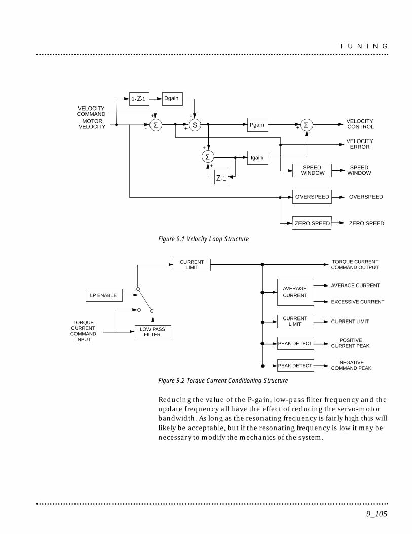
Figure 9.1 Velocity Loop Structure
Figure 9.2 Torque Current Conditioning Structure
Reducing the value of the P-gain, low-pass filter frequency and theupdate frequency all have the effect of reducing the servo-motorbandwidth. As long as the resonating frequency is fairly high this willlikely be acceptable, but if the resonating frequency is low it may benecessary to modify the mechanics of the system.
PEAK DETECT
PEAK DETECT
CURRENT
AVERAGE
LIMIT
CURRENT
CURRENTLIMIT
LP ENABLE
LOW PASSFILTER
TORQUECURRENTCOMMAND
INPUT
TORQUE CURRENTCOMMAND OUTPUT
AVERAGE CURRENT
CURRENT LIMIT
POSITIVECURRENT PEAK
NEGATIVECOMMAND PEAK
EXCESSIVE CURRENT
VELOCITYCOMMAND
MOTORVELOCITY
VELOCITYCONTROL
VELOCITYERROR
SPEEDWINDOW
OVERSPEED
ZERO SPEED
Dgain
+
1-Z-1
Σ- + S-
+
Σ+
Pgain
Igain
Z-1
Σ++
SPEEDWINDOW
OVERSPEED
ZERO SPEED
9_105
T U N I N G

BACKLASH
Backlash between the motor and load effectively unloads the motorover a small angle. Within this small angle, the increased bandwidthcan result in oscillations. Some backlash may be unavoidable,especially with gear reduction. If backlash is present, the inertiamatch between the load and motor must be properly sized for goodservo performance (load inertia should roughly equal motor inertia).Gearing reduces the inertia reflected to the motor by the square ofthe gear reduction from motor to load. Therefore, the gear ratio mustprovide the required match.
Auto Tune Mode
The Auto Tune mode uses a “self-tuning” algorithm that automaticallyadjusts the drive’s velocity loop gain parameters. Adjustments do notrequire special equipment. This mode will tune a drive for constantvelocity loop response across different applications. The results oftenprovide acceptable response, but in general should be considered astarting point.
Tuning parameters adjustments are set to achieve a reasonablebandwidth and servo response based on the system inertia andfriction. Auto Tune may be used when a significant amount ofcompliance or backlash exists (for example, belt systems) in themechanical load, but precise tuning requires the load be fullycoupled to the motor. Instability problems occur when the loadis not fully coupled to the motor.
NOTE: The Auto Tune algorithm will not provide satisfactory resultsin systems with significant gravitational effects.
T U N I N G
9_106
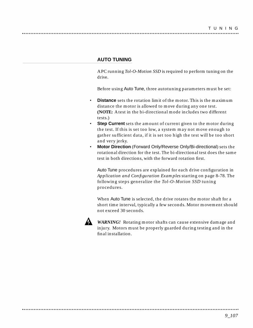
AUTO TUNING
A PC running Tol-O-Motion SSD is required to perform tuning on thedrive.
Before using Auto Tune, three autotuning parameters must be set:
• Distance sets the rotation limit of the motor. This is the maximumdistance the motor is allowed to move during any one test.(NOTE: A test in the bi-directional mode includes two differenttests.)
• Step Current sets the amount of current given to the motor duringthe test. If this is set too low, a system may not move enough togather sufficient data, if it is set too high the test will be too shortand very jerky.
• Motor Direction (Forward Only/Reverse Only/Bi-directional) sets therotational direction for the test. The bi-directional test does the sametest in both directions, with the forward rotation first.
Auto Tune procedures are explained for each drive configuration inApplication and Configuration Examples starting on page 8-78. Thefollowing steps generalize the Tol-O-Motion SSD tuningprocedures.
When Auto Tune is selected, the drive rotates the motor shaft for ashort time interval, typically a few seconds. Motor movement shouldnot exceed 30 seconds.
WARNING! Rotating motor shafts can cause extensive damage andinjury. Motors must be properly guarded during testing and in thefinal installation.
9_107
T U N I N G

1. Choose the Tuning command icon from the Drive window.
2. Choose Auto Tune from the Tuning window. This activates the AutoTune command and Motor Direction boxes within the Tuningwindow. Then enter or select:
• appropriate values for Distance in the Auto Tune command box,• appropriate values for Step Current in the Auto Tune command
box, and• an appropriate motor rotation in the Motor Direction box on a
PC, either:- BiDirectional, if the motor will be powered in both the
forward and reverse directions.- Forward Only, if the machinery is designed to operate only in
the forward direction.- Reverse Only, if the motor will be powered only in the
reverse direction.
Use the default settings if uncertain about what values to enter. Thedefault settings are set to values appropriate to the drive and motorcombination selected during drive initialization.
3. Enable the drive.
4. Choose Start from the Tuning window. The drive rotates the motorshaft and then motion will cease. The calculated gains are displayedand the drive is disabled.
5. Disable the drive manually.
6. Choose Normal Drive Operation from the Tuning window.
7. Enable the drive.
8. Choose Close to exit the Tuning window.
T U N I N G
9_108
NOTE: Auto tuning does not have a velocity limit, but it does adhere tothe motor Overspeed setting in the Drive Parameters window.
Manual Tune Mode
Manual tuning may be used to adjust the gain settings and filterfrequency of the velocity regulator. The following sections brieflyexplain these settings. An understanding of the function for each typeof gain and filtering will allow the user to effectively tune the system.
Two types of manual tuning are available:• Velocity tuning• Position tuning.
Before manual tuning is invoked, the Velocity, Distance and MotorDirection parameters must be set. Refer to Auto Tune Mode on page9-107 for information on setting these parameters.
The velocity loop should always be tuned before the position loop, asvelocity loop tuning affects the position loop response.
Gain settings and signal filtering are the primary methods to elec-trically tune a system. A understanding of the types of gain and theirpurposes, as well as a general understanding of filtering, are essentialbackground knowledge to properly tune a servo system.
9_109
T U N I N G
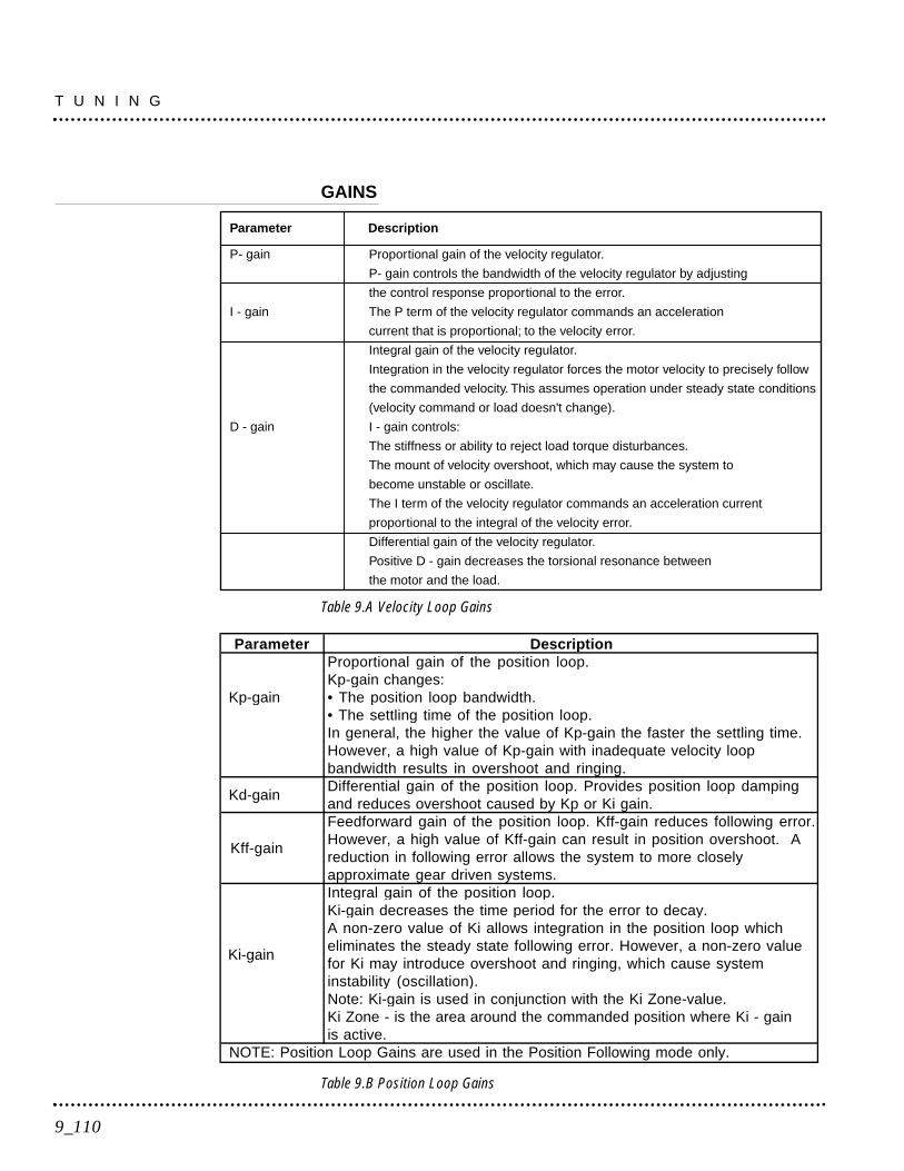
GAINS
Table 9.A Velocity Loop Gains
Table 9.B Position Loop Gains
Parameter DescriptionProportional gain of the position loop.Kp-gain changes:
Kp-gain • The position loop bandwidth.• The settling time of the position loop.In general, the higher the value of Kp-gain the faster the settling time.However, a high value of Kp-gain with inadequate velocity loopbandwidth results in overshoot and ringing.
Kd-gainDifferential gain of the position loop. Provides position loop dampingand reduces overshoot caused by Kp or Ki gain.
Kff-gain
Feedforward gain of the position loop. Kff-gain reduces following error.However, a high value of Kff-gain can result in position overshoot. Areduction in following error allows the system to more closelyapproximate gear driven systems.Integral gain of the position loop.Ki-gain decreases the time period for the error to decay.
Ki-gain
A non-zero value of Ki allows integration in the position loop whicheliminates the steady state following error. However, a non-zero valuefor Ki may introduce overshoot and ringing, which cause systeminstability (oscillation).Note: Ki-gain is used in conjunction with the Ki Zone-value.Ki Zone - is the area around the commanded position where Ki - gainis active.
NOTE: Position Loop Gains are used in the Position Following mode only.
P- gain
I - gain
D - gain
Proportional gain of the velocity regulator.
P- gain controls the bandwidth of the velocity regulator by adjusting
the control response proportional to the error.
The P term of the velocity regulator commands an acceleration
current that is proportional; to the velocity error.
Integral gain of the velocity regulator.
Integration in the velocity regulator forces the motor velocity to precisely follow
the commanded velocity. This assumes operation under steady state conditions
(velocity command or load doesn't change).
I - gain controls:
The stiffness or ability to reject load torque disturbances.
The mount of velocity overshoot, which may cause the system to
become unstable or oscillate.
The I term of the velocity regulator commands an acceleration current
proportional to the integral of the velocity error.
Differential gain of the velocity regulator.
Positive D - gain decreases the torsional resonance between
the motor and the load.
Parameter Description
T U N I N G
9_110
FILTERS
The velocity regulator has one low pass filter. The filter bandwidthrange is from 1 Hz to 992 Hz.
The filter serves two purposes:
• Adjust the frequency range to remove or filter the noise producedby encoder resolution.
• Reduce the amount of the mechanical resonance in the mech-anical system (e.g., belt systems).
Similar results may often be achieved by reducing the update rate ofthe velocity loop.
MANUAL TUNING
Manual tuning may be used to adjust the gain control parameters P,I, D and the filters. A square wave is generated by the drive to assistin the adjustment. Manual velocity tuning requires the following:
• Step Period value to be specified• Step Velocity value to be specified.
NOTE: Always tune the velocity loop before the position loop, asVelocity loop tuning affects the position loop response.
9_111
T U N I N G
TUNING THE VELOCITY LOOP
The Auto Tune procedure provides a starting point for velocity looptuning. Manual tuning is desirable when very precise adjustmentsare required.
The following steps describe how to manually tune the velocity loop.These steps precede the manual position loop tuning procedure,which should follow velocity loop tuning.
1. Disable the drive.
2. Choose Manual Tune (Velocity Step) from the Tuning window.
3. Enter the desired step Velocity (rpm) of the internal square wavegenerator.
4. Enter the desired Time to complete one cycle of the square wave ofthe internal step velocity.
5. Select the desired Motor Direction (Forward Only, Reverse Only, or Bi-Directional).
6. Select the Oscilloscope.
7. Enable the drive.
8. Choose Start. The motor should start moving and the oscilloscopewill display the commanded velocity and the motor velocity.
9. While monitoring the motor velocity waveform, increase P-gainuntil the desired rise time is achieved.
10. While monitoring the motor velocity waveform, increase I-gain untilan acceptable amount of overshoot is reached.
11. Apply filtering by selecting Filters, and then select Filter Enable.
12. While monitoring the motor velocity waveform, decrease the filterBandwidth until the overshoot begins to increase (in many applica-tions the filter is not necessary).
T U N I N G
9_112
13. Choose Stop.
14. Disable the drive.
15. Choose Normal Drive Operation.
16. Choose Close.
17. Enable the drive.
The drive’s velocity loop is tuned.
TUNING THE POSITION LOOP
Specify the step period and step position values, and then input asquare wave to the position loop. Adjust the gain controls parametersKp, Kd, Kff, Ki, and Ki Zone Filters to tune the system.
NOTE: Tune the velocity loop before attempting to tune the positionloop. The bandwidth of the velocity loop must be set before positionloop tuning is attempted.
1. Disable the drive.
2. Choose Manual Tune (Position Step) from the Tuning window.
3. Enter an appropriate Distance Count (Step Position) for the internalsquare wave.
4. Enter an appropriate time to complete one cycle of the square wavefor the internal step position.
5. Select the desired Motor Direction (Bi-Directional, Forward Only orReverse Only).
6. Select the Oscilloscope.
7. Enable the drive.
9_113
T U N I N G

8. Choose Start. The motor will move and the oscilloscope will displaythe Position Motor Feedback signal.
9. Increase the Kp gain while monitoring the signal on the scope. TheKp gain should be adjusted until the desired rise time is achieved,with no overshoot. Refer to Figure 9.3.
10. Increase Ki very slowly until the signal begins to overshoot.
11. Increase Kd very slowly to remove the overshoot caused by Ki.
12. In general Kff gain may continue to be set to 100.
13. Choose Stop.
14. Disable the drive.
15. Choose Normal Drive Operation.
16. Choose Close.
17. Enable the drive.
The position loop has been tuned. The drive may be operated as amaster encoder, step/direction or step up/down configuration.
T U N I N G
9_114
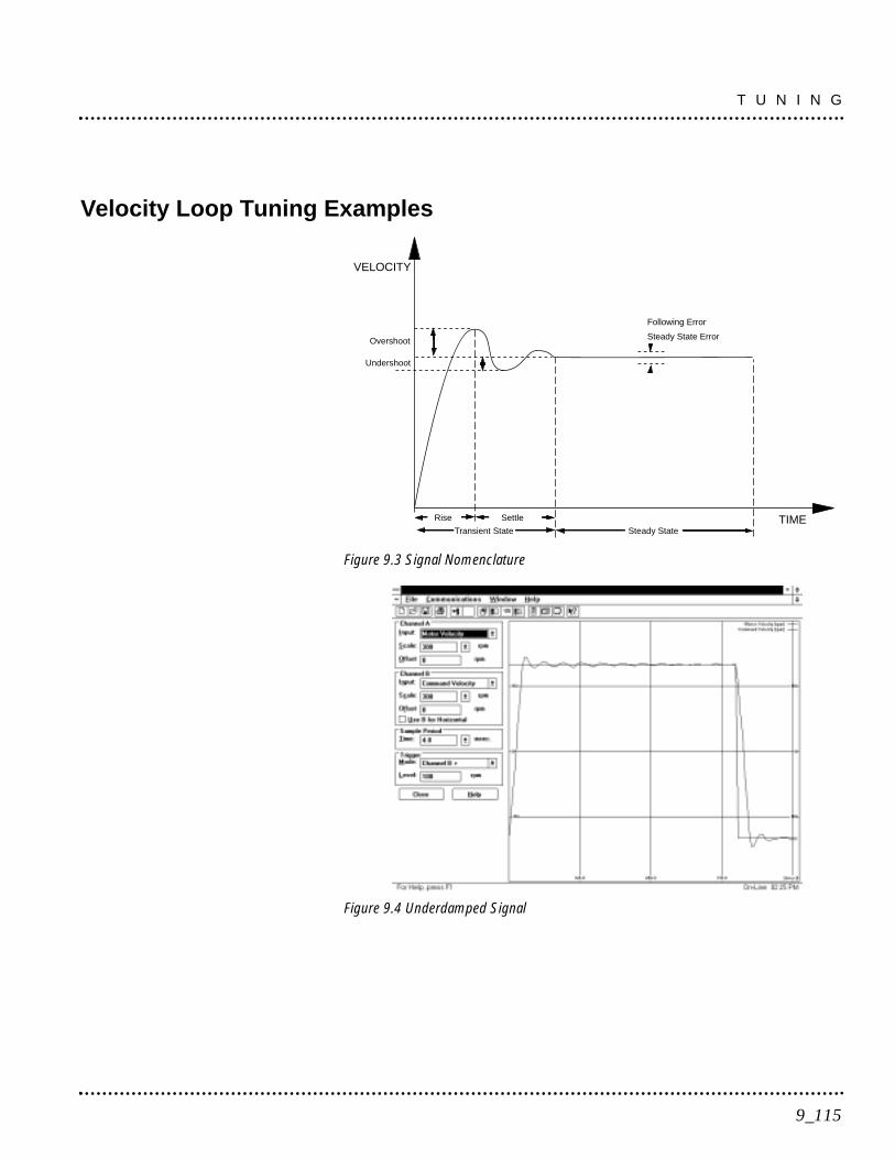
Velocity Loop Tuning Examples
Figure 9.3 Signal Nomenclature
Figure 9.4 Underdamped Signal
Transient State
VELOCITY
TIMESettleRise
Following Error
Steady State ErrorOvershoot
Steady State
Undershoot
9_115
T U N I N G
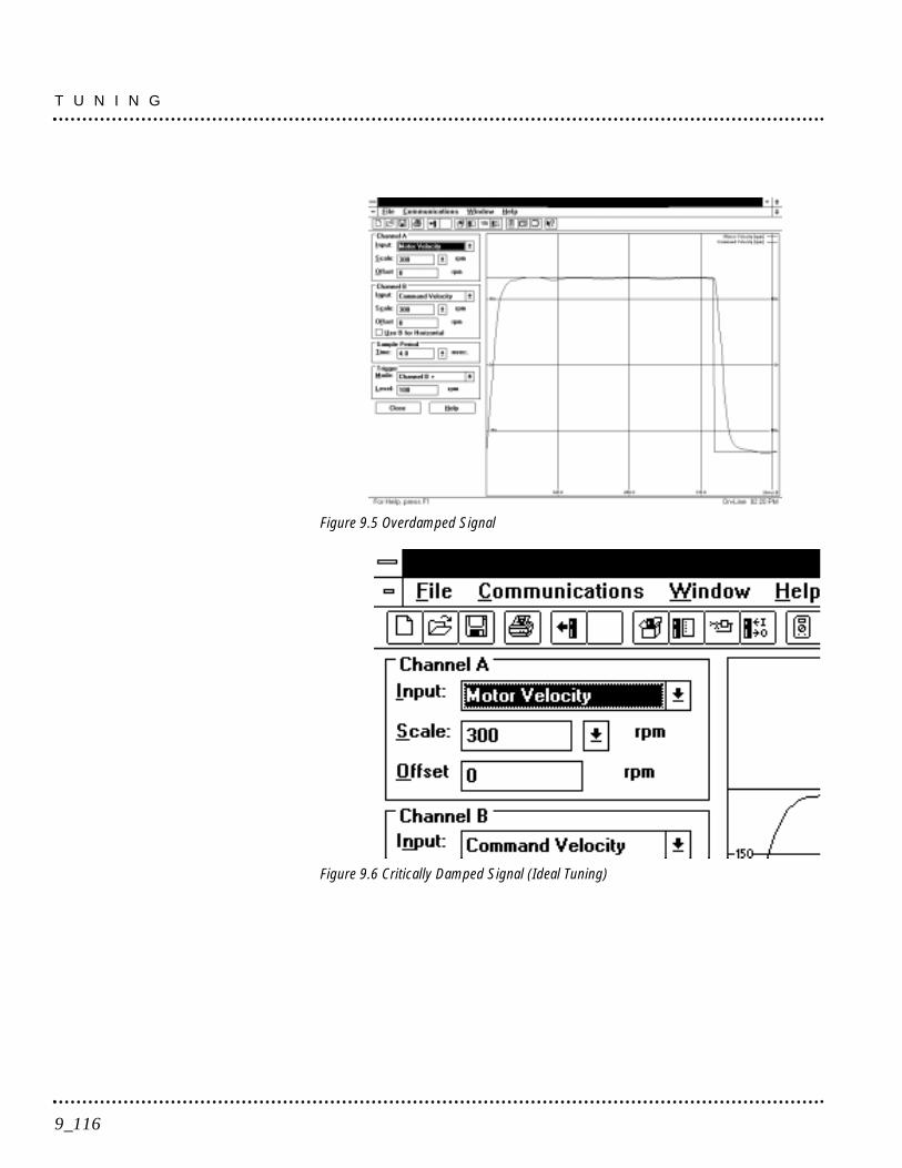
Figure 9.5 Overdamped Signal
Figure 9.6 Critically Damped Signal (Ideal Tuning)
T U N I N G
9_116

A single front panel indicator displays the status of the drive on acontinuous basis:
• The Status LED lights whenever the bus is energized.
Status Indicator
The Status Indicator is a three-level LED which indicates the currentoperational state of the drive. The status level is indicated by the colorof the LED.
• Green = Normal operation• Blinking Green/Orange = Drive Fault• Orange = Hardware malfunction• Blank = Power not supplied or hardware malfunction
Refer to Troubleshooting beginning on page 11-123 for trouble-shooting tables.
Error Messages
If there is a fault, the specific error messages may be accessed byattaching a PC to the SSD drive. Faults are detected by the drive intwo ways: power-up hardware and time-run faults. A power-upfault usually requires servicing of the hardware, while a run-timefault can be cleared by resetting the drive.
Run Time fault handling executes every 1 millisecond (1 kHz rate).Thus the maximum time interval between an error occurring anddisplay of the fault action is 1 millisecond.
Maintaining and Troubleshooting the SSD Line lists error codes andpossible actions or solutions to take when resolving the errorcondition.
10_117
Status Display10

RUN TIME ERROR CODES
Table 10.A Run Time Error Codes
POWER-UP ERROR CODES
A power-up error indicated in almost all cases that the drive shouldbe returned to the factory for service. In general, any occurrence of aPower-up error should be treated with extreme caution. It mayindicate the hardware is marginal.
Situations that may cause drive hardware errors, and which can beremedied outside the factory include:
• A watchdog time-out error may result from electrical “noise”(electromagnetic interference - EMI), a firmware error, or ahardware malfunction. The context of the watchdog error needsto be investigated to determine the source of the problem.
Error Code Fault Description 01 - 03 Reserved
04 Motor Overtemperature, Thermostat 05 IPM Fault (Overtemperature/Overcurrent/Short Circuit)
06 - 08 Reserved 09 Bus Undervoltage10 Bus Overvoltage11 Illegal Hall State
12 - 16 Reserved17 Excessive Average Current18 Motor Overspeed19 Excessive Following Error20 Motor Encoder State Error21 Auxiliary Encoder State Error22 Motor Thermal Protection23 IPM Thermal Protection24 Excess Velocity Error25 Communication Angle Error
26-27 Reserved28 No Motor Selected29 Motor Selection not in Table30 EEPROM Write Error
31-50 Reserved
S T A T U S D I S P L A Y
10_118
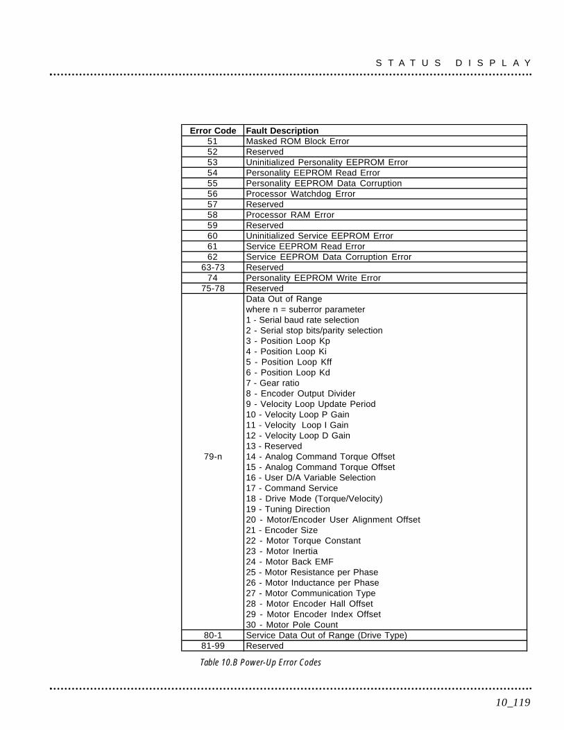
Table 10.B Power-Up Error Codes
Error Code Fault Description51 Masked ROM Block Error52 Reserved53 Uninitialized Personality EEPROM Error54 Personality EEPROM Read Error55 Personality EEPROM Data Corruption56 Processor Watchdog Error57 Reserved58 Processor RAM Error59 Reserved60 Uninitialized Service EEPROM Error61 Service EEPROM Read Error62 Service EEPROM Data Corruption Error
63-73 Reserved74 Personality EEPROM Write Error
75-78 ReservedData Out of Rangewhere n = suberror parameter1 - Serial baud rate selection2 - Serial stop bits/parity selection3 - Position Loop Kp4 - Position Loop Ki5 - Position Loop Kff6 - Position Loop Kd7 - Gear ratio8 - Encoder Output Divider9 - Velocity Loop Update Period10 - Velocity Loop P Gain11 - Velocity Loop I Gain12 - Velocity Loop D Gain13 - Reserved
79-n 14 - Analog Command Torque Offset15 - Analog Command Torque Offset16 - User D/A Variable Selection17 - Command Service18 - Drive Mode (Torque/Velocity)19 - Tuning Direction20 - Motor/Encoder User Alignment Offset21 - Encoder Size22 - Motor Torque Constant23 - Motor Inertia24 - Motor Back EMF25 - Motor Resistance per Phase26 - Motor Inductance per Phase27 - Motor Communication Type28 - Motor Encoder Hall Offset29 - Motor Encoder Index Offset30 - Motor Pole Count
80-1 Service Data Out of Range (Drive Type)81-99 Reserved
10_119
S T A T U S D I S P L A Y

S T A T U S D I S P L A Y
10_120
This section provides a description of suggested maintenanceactivities and an in-depth troubleshooting chart
Maintenance
The SSD drive is designed to function with minimum maintenance.
DANGER! DC bus capacitors may retain hazardous voltages afterinput power has been removed, but will normally discharge in severalseconds. Before working on the drive, measure the DC bus voltage toverify it has reached a safe level or wait the full time interval listed onthe warning on the front of the drive. Failure to observe this pre-caution could result in severe bodily injury or loss of life.
PERIODIC MAINTENANCE
Normally the only maintenance required is removal of superficialdust and dirt from the drive and a quick check of cabling insulationand connections.
CleaningTo clean the drive, use an OSHA-approved nozzle that providescompressed air under low pressure <20 kPa (30 psi) to blow theexterior surface and the vents clean.
Cable InspectionInspect the cables, particularly the power connections, to verify theconnection.• All power connections should be torqued to 1.2 Nm (11 lb-in).• D-shell connectors can be inspected for proper seating and
signal continuity.• Visually inspect all cables for abrasion.
Data TransferAfter the drive has been configured and tuned, the data stored in theEEPROM personality module should be saved off-line. Saving theparameters off line will allow several machines to be cloned with thesame mechanics and provides an emergency backup of the drive data.
11_121
Maintenance & Troubleshooting11
To transfer the data from the drive to a PC:1. While on-line with a drive, click on File in the toolbar menu
2. Select Save As..., the Save As window will appear
3. Enter the file name and press ENTER or choose OK to save.
To transfer the data from a PC to a drive:1. Close all windows in Tol-O-Motion SSD.
2. Choose File in the toolbar menu.
3. Choose Open.
4. Select the desired file name or enter the file name to be loaded andpress ENTER or choose OK.
If the name of the file to be loaded is unknown, select the correctdirectory from the Directories box and select the file name from thedisplayed list of file names. The Tol-O-Motion SSD Off-Line Drivewindow will appear along with the selected file name.
5. Select Communications from the toolbar menu
6. Select Overwrite Drive Parameters. The Drive Select window willappear.
7. Select the drive to be configured, and then press ENTER or chooseOK to load the parameters into the personality module.
M A I N T E N A N C E & T R O U B L E S H O O T I N G
11_122

Troubleshooting
A single LED on the front panel indicates the status of the drive on acontinuous basis:
• Green = Normal operation• Blinking Green/Orange = Drive Fault• Orange = Hardware malfunction• Blank = Power not supplied or hardware malfunction
A table of problems, potential causes, and appropriate actions totake to resolve the problem is included below.
If problems persist after attempting to carefully troubleshoot thesystem, please contact the nearest distributor of Tol-O-Matic productsfor further assistance.
ERROR CODES
Error codes may be accessed by attaching a PC with Tol-O-MotionSSD software to the serial port (J3):
• Tol-O-Motion SSD displays errors in two windows: Fault History andDisplay Fault Status;
11_123
M A I N T E N A N C E & T R O U B L E S H O O T I N G
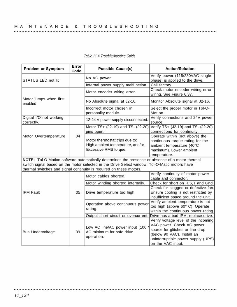
Table 11.A Troubleshooting Guide
Problem or SymptomErrorCode
Possible Cause(s) Action/Solution
STATUS LED not litNo AC power
Verify power (115/230VAC singlephase) is applied to the drive.
Internal power supply malfunction. Call factory.
Motor encoder wiring error.Check motor encoder wiring errorwiring. See Figure 6.37.
Motor jumps when firstenabled
No Absolute signal at J2-16. Monitor Absolute signal at J2-16.
Incorrect motor chosen inpersonality module.
Select the proper motor in Tol-O-Motion.
Digital I/O not workingcorrectly.
24V power supply disconnected.Verify connections and 24V powersource.
Motor TS+ (J2-19) and TS- (J2-20)pins open.
Verify TS+ (J2-19) and TS- (J2-20)connections for continuity.
Motor Overtemperature 04Motor thermostat trips due to:High motor ambient temperature,and/or Excessive RMS torque.
Operate within (not above) thecontinuous torque rating for theambient temperature (40°Cmaximum). Lower ambienttemperature.
NOTE: Tol-O-Motion software automatically determines the presence or absence of a motor thermalswitch signal based on the motor selected in the Drive Select window. Tol-O-Matic motors havethermal switches and signal continuity is required on these motors.
Motor cables shorted.Verify continuity of motor powercable and connector.
Motor winding shorted internally. Check for short on R,S,T and Gnd.
IPM Fault 05 Drive temperature too high.Check for clogged or defective fan.Ensure cooling is not restricted byinsufficient space around the unit.
Operation above continuous powerrating.
Verify ambient temperature is nottoo high (above 60° C). Operatewithin the continuous power rating.
Output short circuit or overcurrent. Drive has a bad IPM, replace drive.
Bus Undervoltage 09Low AC line/AC power input (100 VAC minimum for safe driveoperation.
Verify voltage level of the incomingVAC power. Check AC powersource for glitches or line drop(below 90 VAC). Install anuninterruptible power supply (UPS)on the VAC input.
M A I N T E N A N C E & T R O U B L E S H O O T I N G
11_124
12-24 V power supply disconnected.
Motor thermostat trips due to:High ambient temperature, and/orExcessive RMS torque.
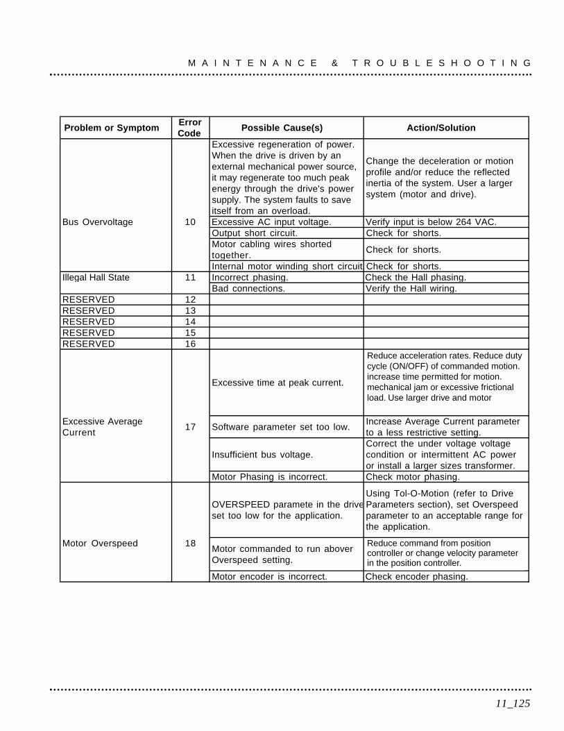
11_125
M A I N T E N A N C E & T R O U B L E S H O O T I N G
Problem or SymptomErrorCode
Possible Cause(s) Action/Solution
Excessive regeneration of power.When the drive is driven by anexternal mechanical power source,it may regenerate too much peakenergy through the drive's powersupply. The system faults to saveitself from an overload.
Change the deceleration or motionprofile and/or reduce the reflectedinertia of the system. User a largersystem (motor and drive).
Bus Overvoltage 10 Excessive AC input voltage. Verify input is below 264 VAC.Output short circuit. Check for shorts.Motor cabling wires shortedtogether.
Check for shorts.
Internal motor winding short circuit.Check for shorts.Illegal Hall State 11 Incorrect phasing. Check the Hall phasing.
Bad connections. Verify the Hall wiring.RESERVED 12RESERVED 13RESERVED 14RESERVED 15RESERVED 16
Excessive time at peak current.
Reduce acceleration rates. Reduceduty cycle (ON/OFF) of commandedmotion. Increase time permitted formotion. Mechanical jam or excessivefrictional load. User larger drive andmotor.
Excessive AverageCurrent
17 Software parameter set too low.Increase Average Current parameterto a less restrictive setting.
Insufficient bus voltage.Correct the under voltage voltagecondition or intermittent AC poweror install a larger sizes transformer.
Motor Phasing is incorrect. Check motor phasing.
OVERSPEED paramete in the driveset too low for the application.
Using Tol-O-Motion (refer to DriveParameters section), set Overspeedparameter to an acceptable range forthe application.
Motor Overspeed 18Motor commanded to run aboverOverspeed setting.
Reduce command frompositioncontroller or change velocity para-meter in the position controller.
Motor encoder is incorrect. Check encoder phasing.
Reduce acceleration rates. Reduce dutycycle (ON/OFF) of commanded motion.increase time permitted for motion.mechanical jam or excessive frictionalload. Use larger drive and motor
Reduce command from positioncontroller or change velocity parameterin the position controller.
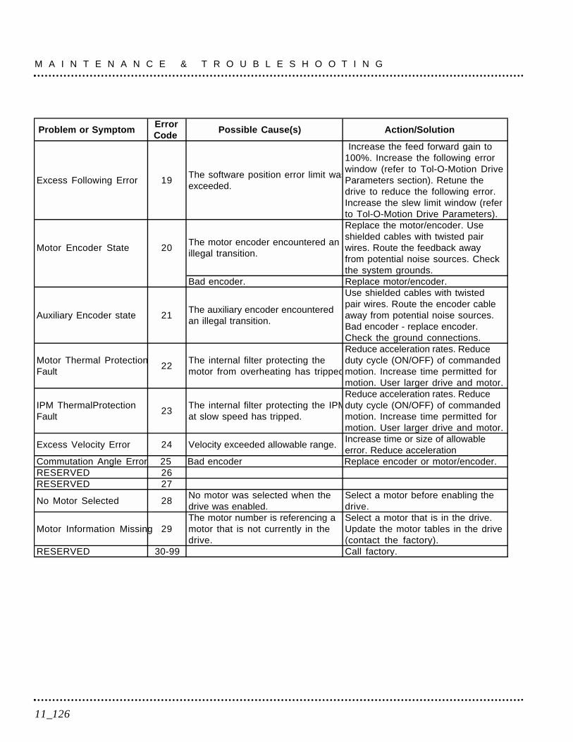
M A I N T E N A N C E & T R O U B L E S H O O T I N G
11_126
Problem or SymptomErrorCode
Possible Cause(s) Action/Solution
Excess Following Error 19The software position error limit wasexceeded.
Increase the feed forward gain to100%. Increase the following errorwindow (refer to Tol-O-Motion DriveParameters section). Retune thedrive to reduce the following error.Increase the slew limit window (referto Tol-O-Motion Drive Parameters).
Motor Encoder State 20The motor encoder encountered anillegal transition.
Replace the motor/encoder. Useshielded cables with twisted pairwires. Route the feedback awayfrom potential noise sources. Checkthe system grounds.
Bad encoder. Replace motor/encoder.
Auxiliary Encoder state 21The auxiliary encoder encounteredan illegal transition.
Use shielded cables with twistedpair wires. Route the encoder cableaway from potential noise sources.Bad encoder - replace encoder.Check the ground connections.
Motor Thermal ProtectionFault
22The internal filter protecting themotor from overheating has tripped
Reduce acceleration rates. Reduceduty cycle (ON/OFF) of commandedmotion. Increase time permitted formotion. User larger drive and motor.
IPM ThermalProtectionFault
23The internal filter protecting the IPMat slow speed has tripped.
Reduce acceleration rates. Reduceduty cycle (ON/OFF) of commandedmotion. Increase time permitted formotion. User larger drive and motor.
Excess Velocity Error 24 Velocity exceeded allowable range.Increase time or size of allowableerror. Reduce acceleration
Commutation Angle Error 25 Bad encoder Replace encoder or motor/encoder.RESERVED 26RESERVED 27
No Motor Selected 28No motor was selected when thedrive was enabled.
Select a motor before enabling thedrive.
Motor Information Missing 29The motor number is referencing amotor that is not currently in thedrive.
Select a motor that is in the drive.Update the motor tables in the drive(contact the factory).
RESERVED 30-99 Call factory.

RS-232 COMMUNICATION TEST
This test verifies communications between a SSD drive and an MS-DOS® based personal computer.
Test equipment requirements are:• A PC running Tol-O-Motion SSD• The Terminal mode available in Microsoft® Windows®.
1. Close all Tol-O-Motion SSD windows.
2. Select Communication from Tol-O-Motion SSD and verify communi-cation settings.
3. Verify the communication cable pin out and check cable continuity.Refer to RS-232 Connection Diagrams on page 6-66.
4. If the communication cable is OK, do the following:A. Disconnect the communication cable from the drive (but leave
the cable connected to the PC).B. Jumper pins 2 and 3 on the D connector of the communication
cable.C. Close and exit from Tol-O-Motion SSD.D. Select the Terminal from the Program Manager (Terminal is
usually in the Accessories group).E. Select Settings from the Main menu:
- Select Terminal Emulation from the drop down menu,- Choose DEC VT-100,- Choose OK to close the dialog box.
F. Select Settings from the Main menu- Select Communications from the drop down menu.- Choose COM1 (or the number of the communication port
the drive is connected to) from the Connections sliding list.- Set Baud Rate to 9600.- Set Data Bits to 8.- Set Stop Bits to 1.- Set Parity to NONE.- Set Flow Control to XON/XOFF.- Choose OK to close the dialog box.
11_127
M A I N T E N A N C E & T R O U B L E S H O O T I N G
5. Type any character on the keyboard. The character should echo backon the screen.
If you see the character on the screen swap pins 2 and 3, close theWindows terminal and restart Tol-O-Motion SSD.
If the character does not echo back on the screen, do the following:• Disconnect the cable from the PC.• Jumper Pins 2 and 3 on the communication port of the PC.• Type any character on the keyboard.
- If the character echoes back, the communication port is OKand the cable or the connectors are defective. Replace thecommunication cable assembly
- If the character did not echo back, the communication port isdefective. Replace the communication port.
TESTING DIGITAL OUTPUTS
This test verifies the functionality of the selectable outputs.
Test equipment requirements are:• A PC running Tol-O-Motion SSD• A multimeter.
This test assumes there are no error codes displayed, and a 2X VDCpower supply for the I/O is connected.
NOTE: Disconnect the outputs from any external hardware whileperforming this test
1. Disable the drive by opening the switch connecting J1-26 and J1-20
2. From the Drive window, select the Output Diagnostics commandicon.
M A I N T E N A N C E & T R O U B L E S H O O T I N G
11_128

3. Verify each of the Digital Outputs in the Output Diagnostics windowregisters the appropriate readings on a multimeter when the follow-ing values are set:
A. Drive Ready box, then measure the resistance between J1-24 andJ1-25.- If the box is checked, the resistance should read approximately
1 Ohm.- If the box is not checked, the resistance should read very high
(> 1 MOhm).
B. Brake Enable box, then measure the resistance between J1-49and J1-50- If the box is checked, the resistance should read
approximately 1Ohm.- If the box is not checked, the resistance should be very high
(> 1 MOhm).
A load is necessary to test the transistor outputs listed below. A 1kOhm resistor may be connected from the transistor output (J1-42, J1-43, J1-44 or J1-45) to the I/O COM (J1-6).
C. Digital Output 1, then measure the voltage between J1-42 and J1-13.- If the box is checked, the voltmeter should read
approximately +24 VDC- If the box is not checked, the voltmeter should read
approximately 0 VDC
D. Digital Output 2, then measure the voltage between J1-43 and J1-13.- If the box is checked, the voltmeter should read approximately
+24 VDC.- If the box is not checked, the voltmeter should read approxi-
mately 0 VDC.
4. After the test has been completed, select Close to exit OutputDiagnostics window
If it is determined that a digital output is defective, refer to ReturnProcedure on page F-161 to return the unit.
11_129
M A I N T E N A N C E & T R O U B L E S H O O T I N G
TESTING DIGITAL INPUTS
This test verifies the functionality of the selectable inputs.
Test equipment requirements are:- A PC running Tol-O-Motion SSD- A jumper wire.
The test assumes there are no error codes displayed, and the a24VDC power supply is connected to the I/O.
1. Enable the drive by closing the switch connecting J1-26 and J1-20.
2. Choose the I/O Display command icon from the Drive WindowA. Connect J1-20 to J1-26. The Enable indicator activates.B. Connect J1-21 to J1- 26. The Reset Faults indicator activates.C. Connect J1-31 to J1-26. The Input 1 indicator activates.D. Connect J1-32 to J1-26. The Input 2 indicator activates.E. Connect J1-33 to J1-26. The Input 3 indicator activates.
3. Choose Close to exit the I/O Display window.
If it is determined that a digital input is defective, please refer toReturn Procedure on page F-161 to return the unit for repair.
TESTING ANALOG OUTPUT
The following tests verify the functionality of the analog outputs.
Test equipment requirements are:• A PC running Tol-O-Motion SSD.• A voltmeter.
Testing Analog Output 11. Disable the drive, by opening the connections between the ENABLE
input and the I/O PWR.
2. Disconnect the connections to J1-30.
3. Select Output Diagnostics icon from the Drive window.
M A I N T E N A N C E & T R O U B L E S H O O T I N G
11_130
4. Select Analog Output 1 from the Output Diagnostics window.
5. Enter 1000 in the D/A Level box.
6. Connect a DC voltmeter across analog test points A1 and COM. Themeter should read approximately 1 VDC.
7. Repeat Step 5 using different positive or negative values for the D/ALevel. Verify the meter reads the values entered.
If it is determined that the output is defective, refer to ReturnProcedure on page F-161 to return the unit.
TESTING ANALOG INPUT
The following test verifies the functionality of the analog input.
The tests require:• a PC running Tol-O-Motion SSD, and• a 10 kOhm potentiometer.
Testing the Current Limit Input1. Verify the accuracy of the potentiometer with an ohmmeter before
installing.
2. Disable the drive by opening the connections between the ENABLEinput and I/O PWR.
3. Disconnect the connections to J1-27 and J1-28.
4. Connect the 10K potentiometer between J1-27 and J1-28. Refer to J1 -Controller on page 6-35 for a diagram showing the location of the pins.
5. Choose the Drive Signals command icon from Tol-O-Motion SSD.
6. Choose setup, if the Drive Signals setup window is not already active.
11_131
M A I N T E N A N C E & T R O U B L E S H O O T I N G
7. Choose Current - Input Limit + as the analog signal.
8. Choose OK to close the setup window and activate the Drive Signalswindow.
9. Slowly adjust the potentiometer while viewing the Drive Signalswindow. The Current - Input Limit + value should update as thepotentiometer is adjusted.
If it is determined that the analog input is defective, refer to ReturnProcedure on page F-161 to return the unit.
TESTING ENCODER INPUTS
The following test verifies both reception and transmission of theline count from an encoder by the drive.
The tests require:• a PC running Tol-O-Motion SSD, and• a motor encoder.
Testing Encoder Inputs1. Disable the drive by opening the connections between the ENABLE
input and I/O PWR.
2. Choose the Drive Parameters command icon from Tol-O-MotionSSD.
3. Choose Master Encoder as the Command Source.
4. Choose the Drive setup command icon from Tol-O-Motion SSD.
5. Choose Divide by 1 as the Master Encoder Command Input.
M A I N T E N A N C E & T R O U B L E S H O O T I N G
11_132

6. Make the following hardware connections:• Connect the motor encoder to J2.• Jumper the Encoder Inputs to the Encoder Outputs by connecting
the following pins:
J1-7 to J1-14J1-8 to J1-15J1-9 to J1-16J1-10 to J1-17J1-11 to J1-18J1-12 to J1-19
7. Choose the Encoder Diagnostics command icon from Tol-O-MotionSSD.
8. Choose Zero Count for both the Motor Encoder and Master PositionInput.
9. Slowly rotate the encoder shaft by hand while observing the countsfor both the Motor Encoder and Master Position Input. The MotorEncoder and Master Position Input line counts should be equal.
11_133
M A I N T E N A N C E & T R O U B L E S H O O T I N G

M A I N T E N A N C E & T R O U B L E S H O O T I N G
11_134

135
Appendix

136
SSD drives conformance to the European Union Directives iscontingent on:
1. Installation of AC line filters between the power source and the drive,and
2. Use of certified cables.
SSD Drives
Description Part #SSD5 500 Watt Universal Drive, single phase 100-240 VAC @ 50/60 Hz 3600-9600SSD10 1000 Watt Universal Drive, single phase 100-240 VAC @ 50/60 Hz 3600-9601SSD20 2000 Watt Universal Drive, single phase 100-240 VAC @ 50/60 Hz 3600-9602
Cables
Controller Part #J1 to flying lead (4M) 3600-5064
Encoder Part #J2 to MRV (2M) 3600-1162J2 to MRV (4M) 3600-1163J2 to MRV (6M) 3600-1164
Motor Part #MRV to flying lead (6M) 3600-1165
Communication Part #RS232 3600-1173
A_137
Options & AccessoriesA
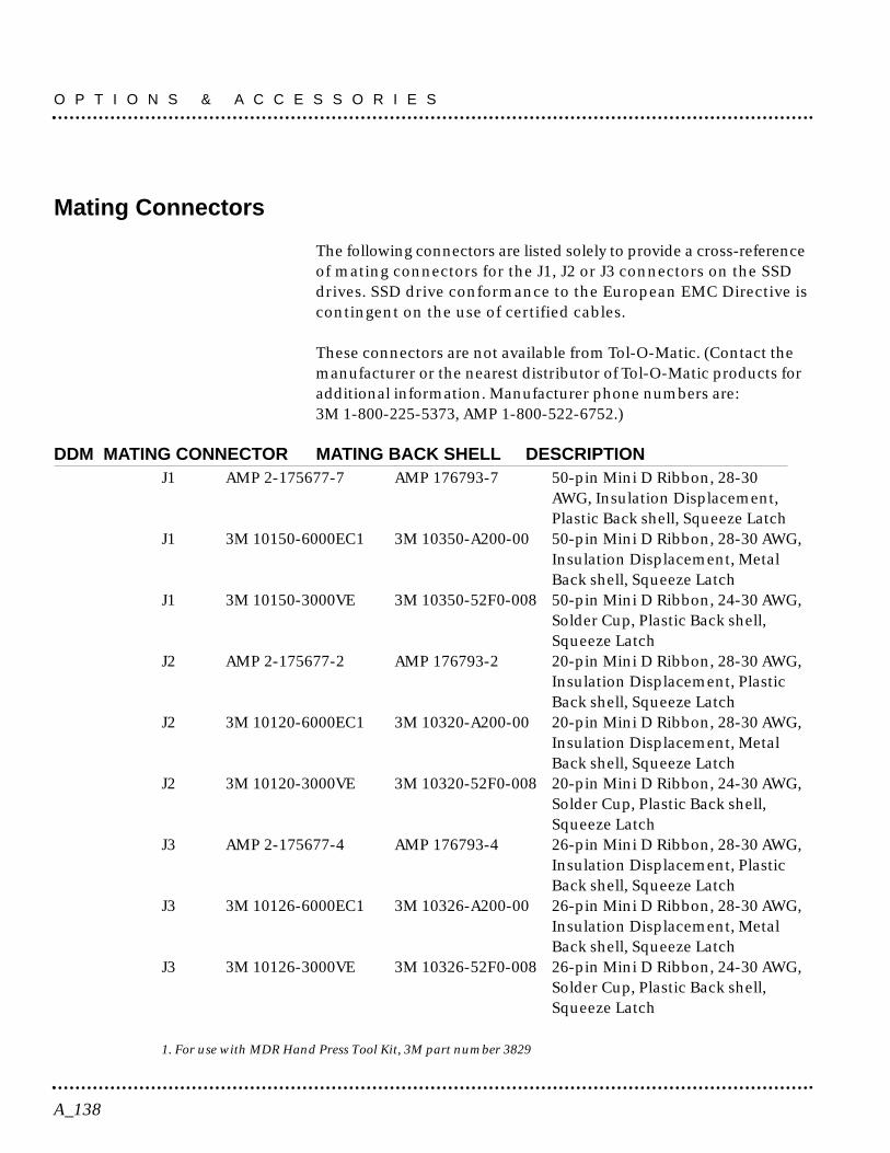
Mating Connectors
The following connectors are listed solely to provide a cross-referenceof mating connectors for the J1, J2 or J3 connectors on the SSDdrives. SSD drive conformance to the European EMC Directive iscontingent on the use of certified cables.
These connectors are not available from Tol-O-Matic. (Contact themanufacturer or the nearest distributor of Tol-O-Matic products foradditional information. Manufacturer phone numbers are:3M 1-800-225-5373, AMP 1-800-522-6752.)
DDM MATING CONNECTOR MATING BACK SHELL DESCRIPTIONJ1 AMP 2-175677-7 AMP 176793-7 50-pin Mini D Ribbon, 28-30
AWG, Insulation Displacement,Plastic Back shell, Squeeze Latch
J1 3M 10150-6000EC1 3M 10350-A200-00 50-pin Mini D Ribbon, 28-30 AWG,Insulation Displacement, MetalBack shell, Squeeze Latch
J1 3M 10150-3000VE 3M 10350-52F0-008 50-pin Mini D Ribbon, 24-30 AWG,Solder Cup, Plastic Back shell,Squeeze Latch
J2 AMP 2-175677-2 AMP 176793-2 20-pin Mini D Ribbon, 28-30 AWG,Insulation Displacement, PlasticBack shell, Squeeze Latch
J2 3M 10120-6000EC1 3M 10320-A200-00 20-pin Mini D Ribbon, 28-30 AWG,Insulation Displacement, MetalBack shell, Squeeze Latch
J2 3M 10120-3000VE 3M 10320-52F0-008 20-pin Mini D Ribbon, 24-30 AWG,Solder Cup, Plastic Back shell,Squeeze Latch
J3 AMP 2-175677-4 AMP 176793-4 26-pin Mini D Ribbon, 28-30 AWG,Insulation Displacement, PlasticBack shell, Squeeze Latch
J3 3M 10126-6000EC1 3M 10326-A200-00 26-pin Mini D Ribbon, 28-30 AWG,Insulation Displacement, MetalBack shell, Squeeze Latch
J3 3M 10126-3000VE 3M 10326-52F0-008 26-pin Mini D Ribbon, 24-30 AWG,Solder Cup, Plastic Back shell,Squeeze Latch
1. For use with MDR Hand Press Tool Kit, 3M part number 3829
O P T I O N S & A C C E S S O R I E S
A_138

Refer to Section A for Mating Connector cross-reference.
Motor Power Connections
MRV23_ and MRV34_
MRV171 Motor supplied with 1 meter flying lead power cable.
Figure B.1 SSD Drive to Motor Power Connector
SSDCONNDESCR
R
S
T
GROUND
WIRECOLOR
RED
WHT
BLK
GRN
MOTORCONNDESCR
R
S
TCASE
GROUND
MOTORCONNPIN #
1
2
3
4
B_139
Cable Diagrams, Schematics & ExamplesB
SSDCONNDESCR
R
S
T
GROUND
MRV171WIRE
COLOR
RED
BLK
WHT
GRN/YEL
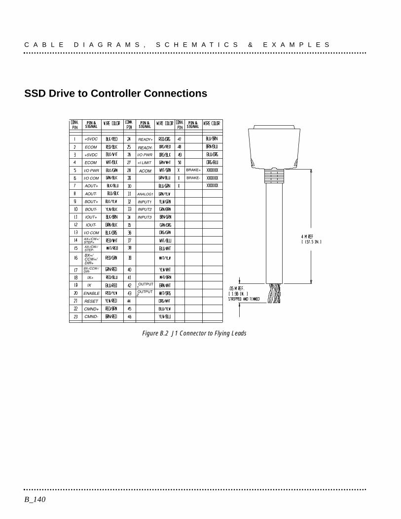
SSD Drive to Controller Connections
Figure B.2 J1 Connector to Flying Leads
PIN &SIGNAL
PIN &SIGNAL
PIN &SIGNAL
C A B L E D I A G R A M S , S C H E M A T I C S & E X A M P L E S
B_140
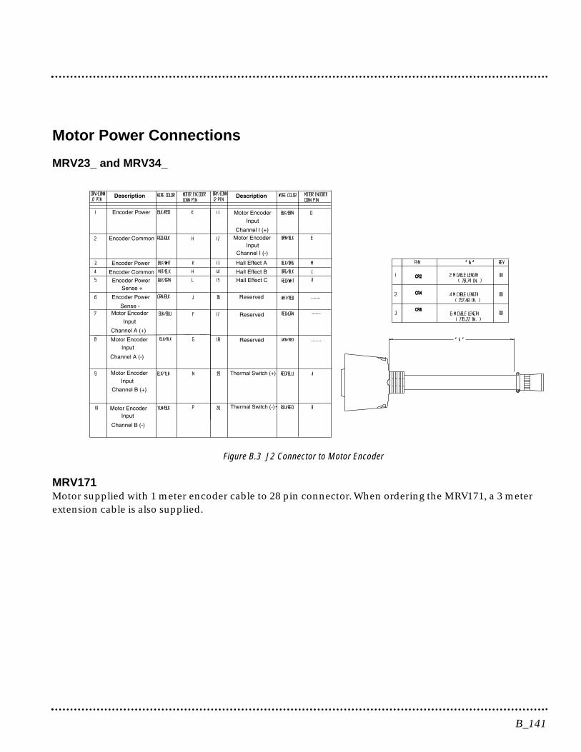
Motor Power Connections
MRV23_ and MRV34_
Figure B.3 J2 Connector to Motor Encoder
MRV171 Motor supplied with 1 meter encoder cable to 28 pin connector. When ordering the MRV171, a 3 meterextension cable is also supplied.
CR2CR2
CR4CR4
CR6CR6
B_141
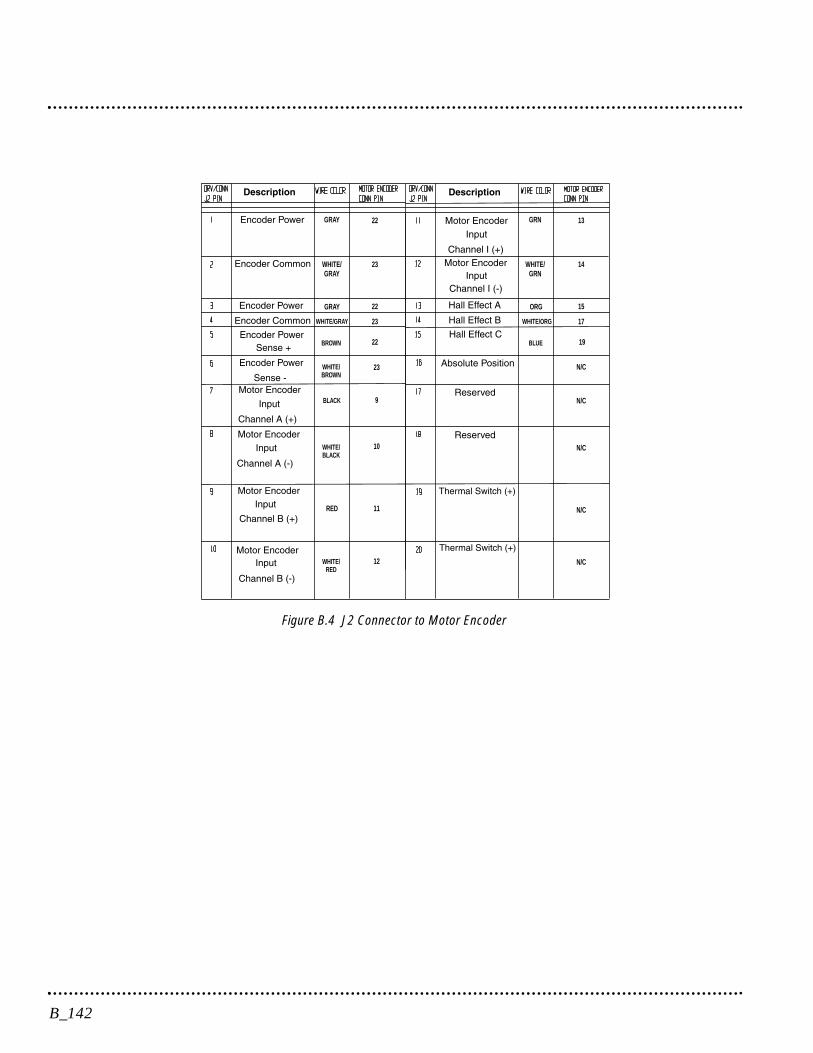
Figure B.4 J2 Connector to Motor Encoder
GRAY GRN
GRAY ORG
RED
WHITE/GRAY
WHITE/GRN
WHITE/GRAY WHITE/ORG
BROWN BLUE
WHITE/BROWN
WHITE/RED
WHITE/BLACK
BLACK
22 13
22 15
23 14
23 17
22 19
23 N/C
N/C
N/C
N/C
N/C
9
10
11
12
B_142

This appendix provides background information about Electro-magnetic Interference (EMI) and machine design guidelines forElectromagnetic Compatibility (EMC). Installation requirements forcompliance to the European Electromagnetic Compatibility Directiveare specified in European Union Requirements on page 5-30. AC LineFilters necessary for European EMC compliance are listed in AC LineFilters on page 5-30.
Introduction
Perhaps no other subject related to the installation of industrialelectronic equipment is so misunderstood as electrical noise. Thesubject is complex and the theory easily fills a book. This sectionprovides guidelines that can minimize noise problems.
The majority of installations do not exhibit noise problems. However,the filtering and shielding guidelines are provided as counter measures.The grounding guidelines provided below are simply good groundingpractices. They should be followed in all installations.
Electrical noise has two characteristics: the generation or emission ofelectromagnetic interference (EMI), and response or immunity toEMI. The degree to which a device does not emit EMI, and is immuneto EMI is called the device’s Electromagnetic Compatibility (EMC).
Equipment which is to be brought into the European Union legallyrequires a specific level of EMC. Since this applies when the equip-ment is brought into use, it is of considerable importance that a drivesystem, as a component of a machine, be correctly installed.
Figure C.1 shows the commonly used EMI model. The model consistsof an EMI source, a coupling mechanism and an EMI victim. Devicessuch as servo drives and computers, which contain switching powersupplies and microprocessors, are EMI sources. The mechanisms forthe coupling of energy between the source and victim are conductionand radiation. Victim equipment can be any electromagnetic devicethat is adversely affected by the EMI coupled to it.
C_143
Electromagnetic Compatibility Guidelinesfor Machine DesignC
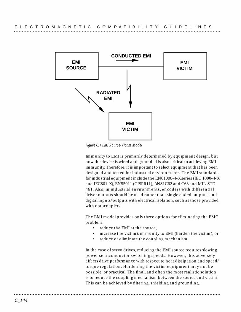
Figure C.1 EMI Source-Victim Model
Immunity to EMI is primarily determined by equipment design, buthow the device is wired and grounded is also critical to achieving EMIimmunity. Therefore, it is important to select equipment that has beendesigned and tested for industrial environments. The EMI standardsfor industrial equipment include the EN61000-4-X series (IEC 1000-4-Xand IEC801-X), EN55011 (CISPR11), ANSI C62 and C63 and MIL-STD-461. Also, in industrial environments, encoders with differentialdriver outputs should be used rather than single ended outputs, anddigital inputs/outputs with electrical isolation, such as those providedwith optocouplers.
The EMI model provides only three options for eliminating the EMCproblem:
• reduce the EMI at the source,• increase the victim’s immunity to EMI (harden the victim), or• reduce or eliminate the coupling mechanism.
In the case of servo drives, reducing the EMI source requires slowingpower semiconductor switching speeds. However, this adverselyaffects drive performance with respect to heat dissipation and speed/torque regulation. Hardening the victim equipment may not bepossible, or practical. The final, and often the most realistic solutionis to reduce the coupling mechanism between the source and victim.This can be achieved by filtering, shielding and grounding.
CONDUCTED EMIEMI
SOURCE
EMIVICTIM
EMIVICTIM
RADIATEDEMI
E L E C T R O M A G N E T I C C O M P A T I B I L I T Y G U I D E L I N E S
C_144

Filtering
As mentioned above, high frequency energy can be coupled betweencircuits via radiation or conduction. The AC power wiring is one ofthe most important paths for both types of coupling mechanisms.The AC line can conduct noise into the drive from other devices, or itcan conduct noise directly from the drive into other devices. It canalso act as an antenna and transmit or receive radiated noise betweenthe drive and other devices.
One method to improve the EMC characteristics of a drive is to use anisolation AC power transformer to feed the amplifier its input power.This minimizes inrush currents on power-up and provides electricalisolation. In addition, it provides common mode filtering, althoughthe effect is limited in frequency by the interwinding capacitance. Useof a Faraday shield between the windings can increase the commonmode rejection bandwidth, (shield terminated to ground) or providedifferential mode shielding (shield terminated to the winding).
NOTE: Common mode noise is present on all conductors referencedto ground. Differential mode noise is present on one conductorreferenced to another conductor.
One alternative is AC line filters to reduce the conducted EMI emittingfrom the drive. This allows nearby equipment to operate undisturbed.In many cases an AC line filter will not be required unless othersensitive circuits are powered off the same AC branch circuit. The basicoperating principle is to minimize the high frequency power transferthrough the filter. An effective filter achieves this by using capacitorsand inductors to mismatch the source impedance (AC line) and theload impedance (drive) at high frequencies.
For drives brought into use in Europe, use of the correct filter isessential to meet emission requirements. Detailed information onfilters is included in the manual and transformers should be usedwhere specified in the manual.
C_145
E L E C T R O M A G N E T I C C O M P A T I B I L I T Y G U I D E L I N E S
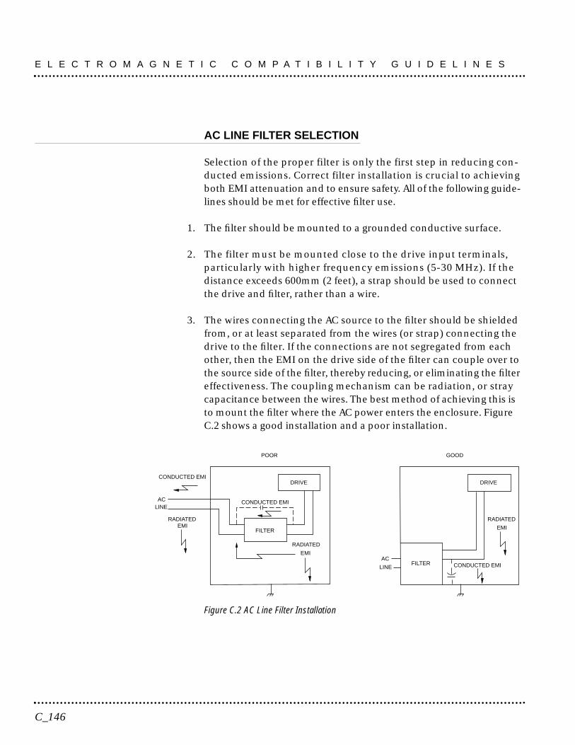
AC LINE FILTER SELECTION
Selection of the proper filter is only the first step in reducing con-ducted emissions. Correct filter installation is crucial to achievingboth EMI attenuation and to ensure safety. All of the following guide-lines should be met for effective filter use.
1. The filter should be mounted to a grounded conductive surface.
2. The filter must be mounted close to the drive input terminals,particularly with higher frequency emissions (5-30 MHz). If thedistance exceeds 600mm (2 feet), a strap should be used to connectthe drive and filter, rather than a wire.
3. The wires connecting the AC source to the filter should be shieldedfrom, or at least separated from the wires (or strap) connecting thedrive to the filter. If the connections are not segregated from eachother, then the EMI on the drive side of the filter can couple over tothe source side of the filter, thereby reducing, or eliminating the filtereffectiveness. The coupling mechanism can be radiation, or straycapacitance between the wires. The best method of achieving this isto mount the filter where the AC power enters the enclosure. FigureC.2 shows a good installation and a poor installation.
Figure C.2 AC Line Filter Installation
ACLINE
RADIATEDEMI
DRIVE
RADIATED
EMI
FILTER
CONDUCTED EMI
CONDUCTED EMI
POOR
AC
LINE
DRIVE
RADIATED
EMI
FILTER CONDUCTED EMI
GOOD
E L E C T R O M A G N E T I C C O M P A T I B I L I T Y G U I D E L I N E S
C_146
When multiple power cables enter an enclosure, an unfiltered linecan contaminate a filtered line external to the enclosure. Therefore,all lines must be filtered to be effective. The situation is similar to aleaky boat. All the holes must be plugged to prevent sinking.
WARNING! Large leakage currents exist in AC line filters.They mustbe grounded properly before applying power. Filter capacitors retainhigh voltages after power removal. Before handling the equipment,voltages should be measured to determine safe levels prior to hand-ling the equipment. Failure to observe this precaution could resultin severe bodily injury.
If the filter is mounted excessively far from the drive, it may be necessaryto mount it to a grounded conductive surface, such as the enclosure, toestablish a high frequency (HF) connection to that surface. To achievethe HF ground, direct contact between the mounting surface and thefilter must be achieved. This may require removal of paint or other in-sulating material from the cabinet or panel.
The only reasonable filtering at the drive output terminals is the use ofinductance. Capacitors would slow the output switching and deterior-ate the drive performance. A common mode choke can be used toreduce the HF voltage at the drive output. This will reduce emissioncoupling through the drive back to the AC line. However, the motorcable still carries a large HF voltage and current. Therefore, it is veryimportant to segregate the motor cable from the AC power cable. Moreinformation on cable shielding and segregation is contained in thesection on shielding. Further information is available from Schaffner (1-800-367-5566) or Roxburgh (01724.281770 [011.44.1724.281770 fromthe USA]).
Grounding
High frequency (HF) grounding is different from safety grounding. Along wire is sufficient for a safety ground, but is completely ineffect-ive as an HF ground due to the wire inductance. As a rule of thumb,a wire has an inductance of 8 nH/in regardless of diameter. At lowfrequencies it acts as a constant impedance, at intermediatefrequencies as an inductor, and at high frequencies as an antenna.The use of ground straps is a better alternative to wires. However
C_147
E L E C T R O M A G N E T I C C O M P A T I B I L I T Y G U I D E L I N E S
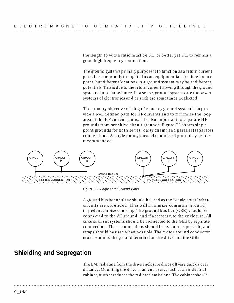
the length to width ratio must be 5:1, or better yet 3:1, to remain agood high frequency connection.
The ground system’s primary purpose is to function as a return currentpath. It is commonly thought of as an equipotential circuit referencepoint, but different locations in a ground system may be at differentpotentials. This is due to the return current flowing through the groundsystems finite impedance. In a sense, ground systems are the sewersystems of electronics and as such are sometimes neglected.
The primary objective of a high frequency ground system is to pro-vide a well defined path for HF currents and to minimize the looparea of the HF current paths. It is also important to separate HFgrounds from sensitive circuit grounds. Figure C3 shows singlepoint grounds for both series (daisy chain) and parallel (separate)connections. A single point, parallel connected ground system isrecommended.
Figure C.3 Single Point Ground Types
A ground bus bar or plane should be used as the “single point” wherecircuits are grounded. This will minimize common (ground)impedance noise coupling. The ground bus bar (GBB) should beconnected to the AC ground, and if necessary, to the enclosure. Allcircuits or subsystems should be connected to the GBB by separateconnections. These connections should be as short as possible, andstraps should be used when possible. The motor ground conductormust return to the ground terminal on the drive, not the GBB.
Shielding and Segregation
The EMI radiating from the drive enclosure drops off very quickly overdistance. Mounting the drive in an enclosure, such as an industrialcabinet, further reduces the radiated emissions. The cabinet should
���������
CIRCUIT1
CIRCUIT2
CIRCUIT3
CIRCUIT1
CIRCUIT2
CIRCUIT3
Ground Bus Bar
PARALLEL CONNECTIONSERIES CONNECTION
E L E C T R O M A G N E T I C C O M P A T I B I L I T Y G U I D E L I N E S
C_148
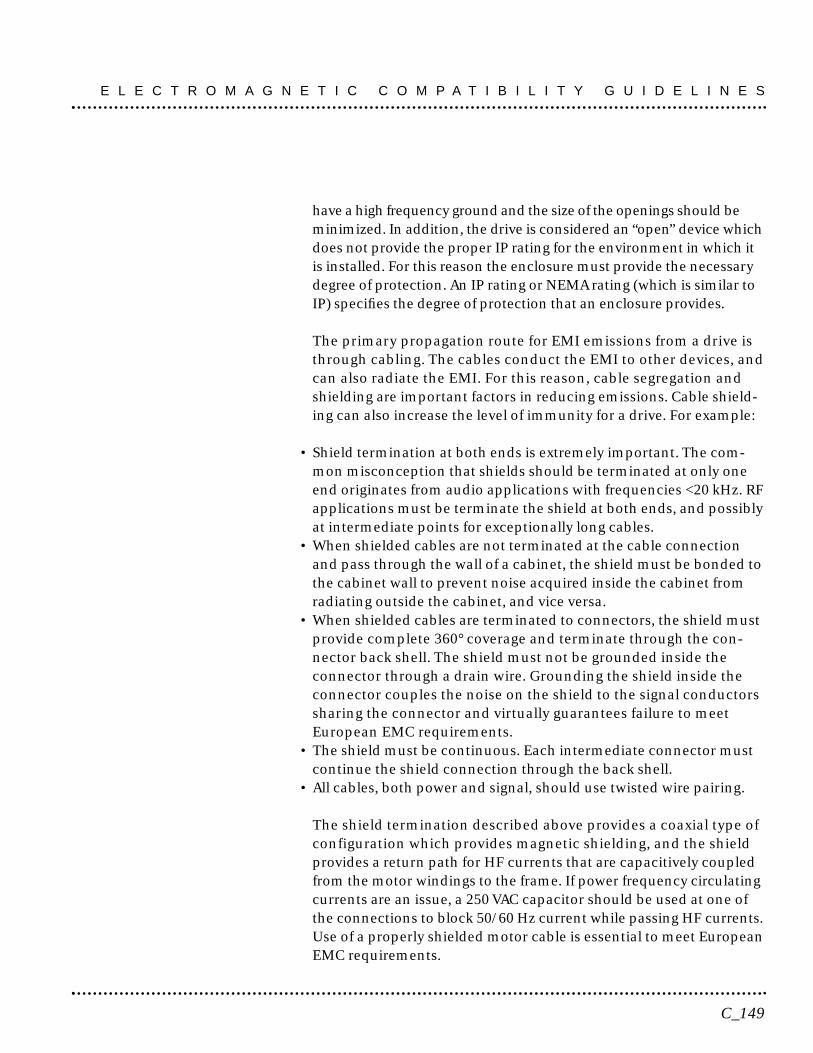
have a high frequency ground and the size of the openings should beminimized. In addition, the drive is considered an “open” device whichdoes not provide the proper IP rating for the environment in which itis installed. For this reason the enclosure must provide the necessarydegree of protection. An IP rating or NEMA rating (which is similar toIP) specifies the degree of protection that an enclosure provides.
The primary propagation route for EMI emissions from a drive isthrough cabling. The cables conduct the EMI to other devices, andcan also radiate the EMI. For this reason, cable segregation andshielding are important factors in reducing emissions. Cable shield-ing can also increase the level of immunity for a drive. For example:
• Shield termination at both ends is extremely important. The com-mon misconception that shields should be terminated at only oneend originates from audio applications with frequencies <20 kHz. RFapplications must be terminate the shield at both ends, and possiblyat intermediate points for exceptionally long cables.
• When shielded cables are not terminated at the cable connectionand pass through the wall of a cabinet, the shield must be bonded tothe cabinet wall to prevent noise acquired inside the cabinet fromradiating outside the cabinet, and vice versa.
• When shielded cables are terminated to connectors, the shield mustprovide complete 360° coverage and terminate through the con-nector back shell. The shield must not be grounded inside theconnector through a drain wire. Grounding the shield inside theconnector couples the noise on the shield to the signal conductorssharing the connector and virtually guarantees failure to meetEuropean EMC requirements.
• The shield must be continuous. Each intermediate connector mustcontinue the shield connection through the back shell.
• All cables, both power and signal, should use twisted wire pairing.
The shield termination described above provides a coaxial type ofconfiguration which provides magnetic shielding, and the shieldprovides a return path for HF currents that are capacitively coupledfrom the motor windings to the frame. If power frequency circulatingcurrents are an issue, a 250 VAC capacitor should be used at one ofthe connections to block 50/60 Hz current while passing HF currents.Use of a properly shielded motor cable is essential to meet EuropeanEMC requirements.
C_149
E L E C T R O M A G N E T I C C O M P A T I B I L I T Y G U I D E L I N E S
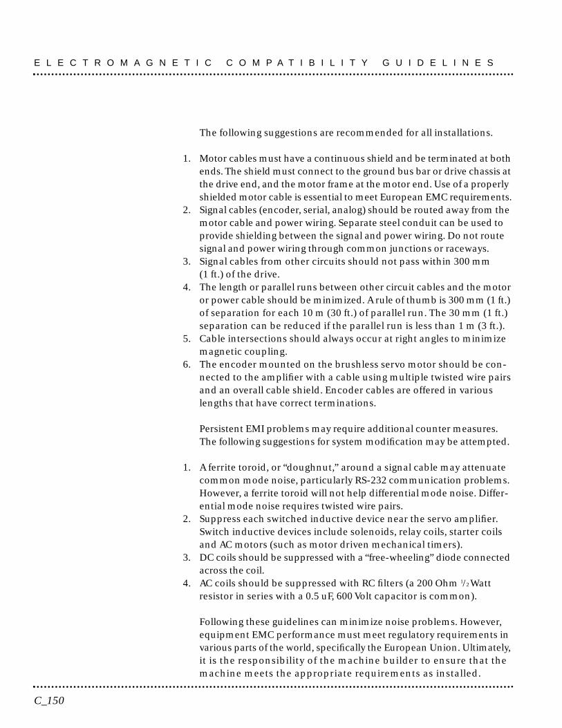
The following suggestions are recommended for all installations.
1. Motor cables must have a continuous shield and be terminated at bothends. The shield must connect to the ground bus bar or drive chassis atthe drive end, and the motor frame at the motor end. Use of a properlyshielded motor cable is essential to meet European EMC requirements.
2. Signal cables (encoder, serial, analog) should be routed away from themotor cable and power wiring. Separate steel conduit can be used toprovide shielding between the signal and power wiring. Do not routesignal and power wiring through common junctions or raceways.
3. Signal cables from other circuits should not pass within 300 mm(1 ft.) of the drive.
4. The length or parallel runs between other circuit cables and the motoror power cable should be minimized. A rule of thumb is 300 mm (1 ft.)of separation for each 10 m (30 ft.) of parallel run. The 30 mm (1 ft.)separation can be reduced if the parallel run is less than 1 m (3 ft.).
5. Cable intersections should always occur at right angles to minimizemagnetic coupling.
6. The encoder mounted on the brushless servo motor should be con-nected to the amplifier with a cable using multiple twisted wire pairsand an overall cable shield. Encoder cables are offered in variouslengths that have correct terminations.
Persistent EMI problems may require additional counter measures.The following suggestions for system modification may be attempted.
1. A ferrite toroid, or “doughnut,” around a signal cable may attenuatecommon mode noise, particularly RS-232 communication problems.However, a ferrite toroid will not help differential mode noise. Differ-ential mode noise requires twisted wire pairs.
2. Suppress each switched inductive device near the servo amplifier.Switch inductive devices include solenoids, relay coils, starter coilsand AC motors (such as motor driven mechanical timers).
3. DC coils should be suppressed with a “free-wheeling” diode connectedacross the coil.
4. AC coils should be suppressed with RC filters (a 200 Ohm 1/2 Wattresistor in series with a 0.5 uF, 600 Volt capacitor is common).
Following these guidelines can minimize noise problems. However,equipment EMC performance must meet regulatory requirements invarious parts of the world, specifically the European Union. Ultimately,it is the responsibility of the machine builder to ensure that themachine meets the appropriate requirements as installed.
E L E C T R O M A G N E T I C C O M P A T I B I L I T Y G U I D E L I N E S
C_150

This appendix provides equations to assist in sizing resistors fordynamic braking.
Introduction
A properly sized resistive load may be required to dynamically brakethe system by dissipating the energy stored in a motor. The sectionEmergency Stop Wiring on page 7-73 depicts the necessary circuitry.
Winding inductance is ignored in this analysis, which allows the loadon the motor winding to be considered as purely resistive whendynamic braking occurs. This simplifies the evaluation to a scalaranalysis, instead of a vector analysis. For simplicity, friction, dampingand load torque also are ignored in the equations.
Dynamic Braking Equations
Equations for the magnitude of instantiates velocity, and per phasecurrent, energy and power are derived by solving the differentialequation governing the motor velocity. The equations are shown below.
Table D.A Dynamic Braking Resistor Parameters
Parameter Description Parameter Description
i(t) Phase Current RLLine-Neutral DynamicBraking Resistance
E(t) Per Phase Energy KEPeak Line-to-Line BackEMF
Jm Motor Inertia KTPeak Line-to-Line TorqueConstant
JL Load Inertia wo Initial Angular VelocityP(t) Per Phase Power w Angular Velocity
RMotor Line-to-LineResistance
t Time
D_151
Dynamic Braking Resistor SelectionD
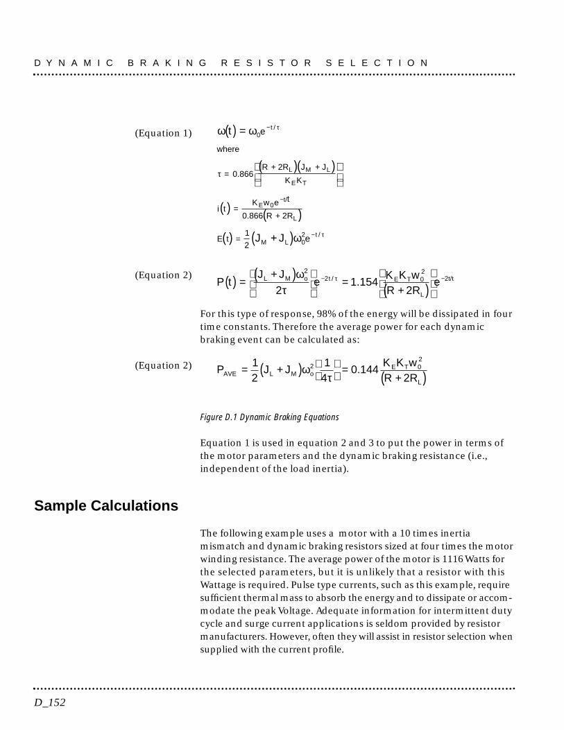
(Equation 1)
(Equation 2)
For this type of response, 98% of the energy will be dissipated in fourtime constants. Therefore the average power for each dynamicbraking event can be calculated as:
(Equation 2)
Figure D.1 Dynamic Braking Equations
Equation 1 is used in equation 2 and 3 to put the power in terms ofthe motor parameters and the dynamic braking resistance (i.e.,independent of the load inertia).
Sample Calculations
The following example uses a motor with a 10 times inertiamismatch and dynamic braking resistors sized at four times the motorwinding resistance. The average power of the motor is 1116 Watts forthe selected parameters, but it is unlikely that a resistor with thisWattage is required. Pulse type currents, such as this example, requiresufficient thermal mass to absorb the energy and to dissipate or accom-modate the peak Voltage. Adequate information for intermittent dutycycle and surge current applications is seldom provided by resistormanufacturers. However, often they will assist in resistor selection whensupplied with the current profile.
P J JK K wR 2RAVE L M
E T 02
L
= +( )
=
+( )12
14
0 1442ωτo .
P tJ J
eK K wR 2R
eL M E T 02
L
2t/t( ) =+( )
=
+( )
− −ω
ττo t
22
21 154/ .
ω ω
ω
τ
τ
τ
t
J J
where
= .R 2R J J
K K
i tK w e t
R 2R
L M L
E T
E 0t/
L
M L
( ) =
( )( )
( ) ( )
( ) +( )
−
−
−
+ +
=+
=
0
02
0 866
0 866
1
2
e
e
t
tE t
/
/
.
D Y N A M I C B R A K I N G R E S I S T O R S E L E C T I O N
D_152
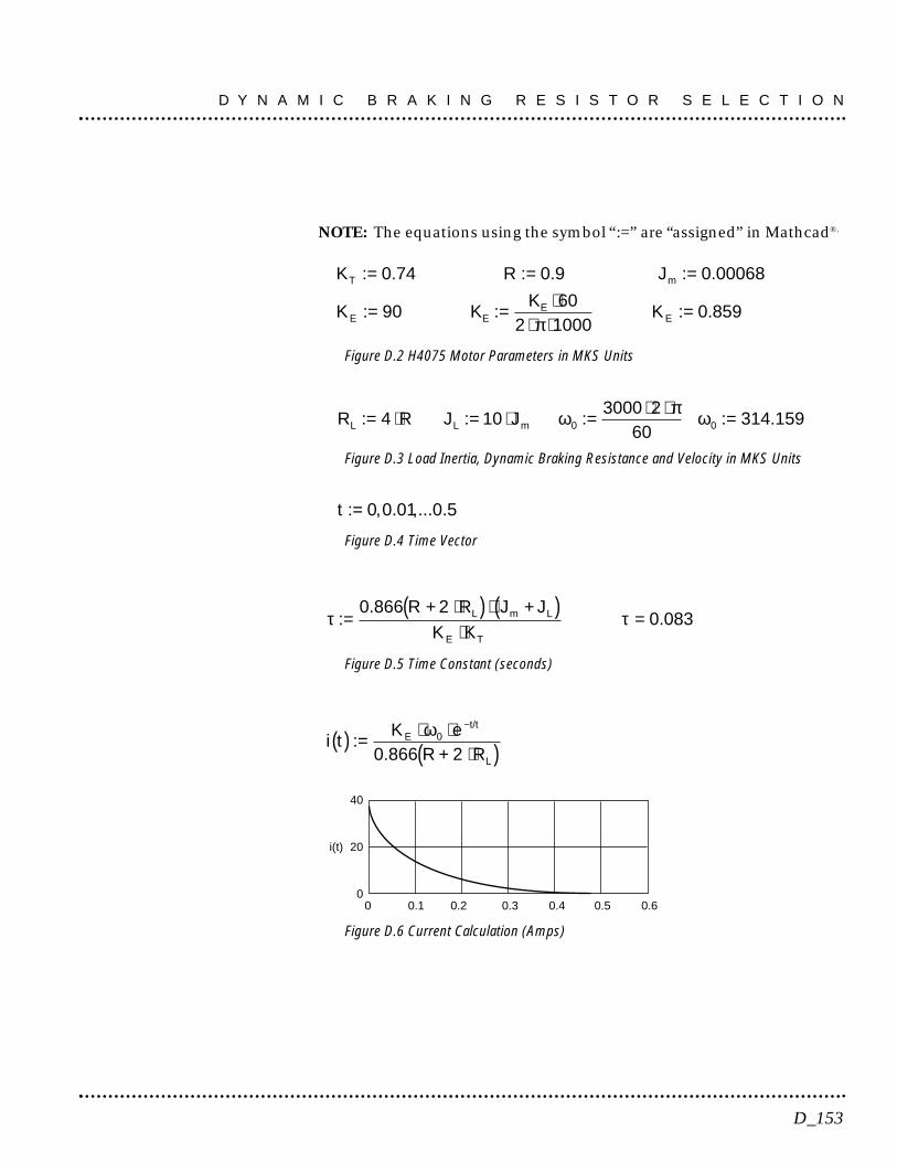
NOTE: The equations using the symbol “:=” are “assigned” in Mathcad®.
Figure D.2 H4075 Motor Parameters in MKS Units
Figure D.3 Load Inertia, Dynamic Braking Resistance and Velocity in MKS Units
Figure D.4 Time Vector
Figure D.5 Time Constant (seconds)
Figure D.6 Current Calculation (Amps)
40
20
00 0.1 0.2 0.3 0.4 0.5 0.6
i(t)
i tK e
R + 2 RE
t/t
L
( ) = ⋅ ⋅⋅( )
−
:.
ω0
0 866
τ τ:.
.=+ ⋅( ) ⋅ +( )
⋅=
0 8660 083
R 2 R J J
K KL m L
E T
t : , . ,... .= 0 0 01 0 5
R R J JL L m: : : : .= ⋅ = ⋅ = ⋅ ⋅ =4 103000 2
60314 1590 0ω π ω
K R J
K K
T m
E E
: . : . : .
: : : .
= = =
= = ⋅⋅ ⋅
=
0 74 0 9 0 00068
9060
2 10000 859K
KE
E
π
D_153
D Y N A M I C B R A K I N G R E S I S T O R S E L E C T I O N
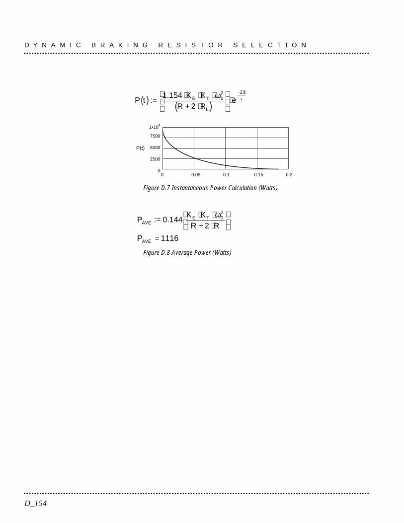
Figure D.7 Instantaneous Power Calculation (Watts)
Figure D.8 Average Power (Watts)
PK K
R 2 R
P
AVEE T 0
2
AVE
: .= ⋅ ⋅+ ⋅
=
0 144
1116
ω
1•104
7500
5000
2500
00 0.05 0.1 0.15 0.2
P(t)
P tK K
R 2 ReE T
L
t
( ) = ⋅ ⋅ ⋅+ ⋅( )
⋅
− ⋅
:.1 154 0
2 2ω τ
D Y N A M I C B R A K I N G R E S I S T O R S E L E C T I O N
D_154
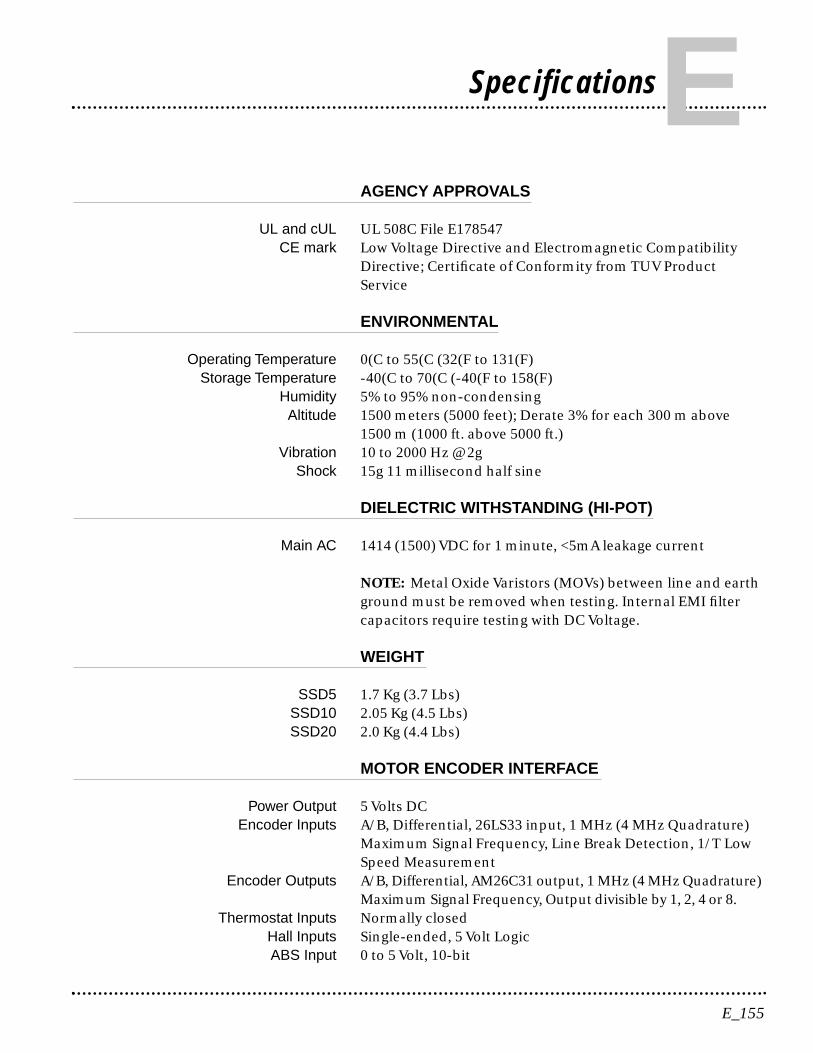
AGENCY APPROVALS
UL and cUL UL 508C File E178547CE mark Low Voltage Directive and Electromagnetic Compatibility
Directive; Certificate of Conformity from TUV ProductService
ENVIRONMENTAL
Operating Temperature 0(C to 55(C (32(F to 131(F)Storage Temperature -40(C to 70(C (-40(F to 158(F)
Humidity 5% to 95% non-condensing Altitude 1500 meters (5000 feet); Derate 3% for each 300 m above
1500 m (1000 ft. above 5000 ft.)Vibration 10 to 2000 Hz @ 2g
Shock 15g 11 millisecond half sine
DIELECTRIC WITHSTANDING (HI-POT)
Main AC 1414 (1500) VDC for 1 minute, <5mA leakage current
NOTE: Metal Oxide Varistors (MOVs) between line and earthground must be removed when testing. Internal EMI filtercapacitors require testing with DC Voltage.
WEIGHT
SSD5 1.7 Kg (3.7 Lbs) SSD10 2.05 Kg (4.5 Lbs)SSD20 2.0 Kg (4.4 Lbs)
MOTOR ENCODER INTERFACE
Power Output 5 Volts DCEncoder Inputs A/B, Differential, 26LS33 input, 1 MHz (4 MHz Quadrature)
Maximum Signal Frequency, Line Break Detection, 1/T LowSpeed Measurement
Encoder Outputs A/B, Differential, AM26C31 output, 1 MHz (4 MHz Quadrature)Maximum Signal Frequency, Output divisible by 1, 2, 4 or 8.
Thermostat Inputs Normally closedHall Inputs Single-ended, 5 Volt LogicABS Input 0 to 5 Volt, 10-bit
E_155
SpecificationsE
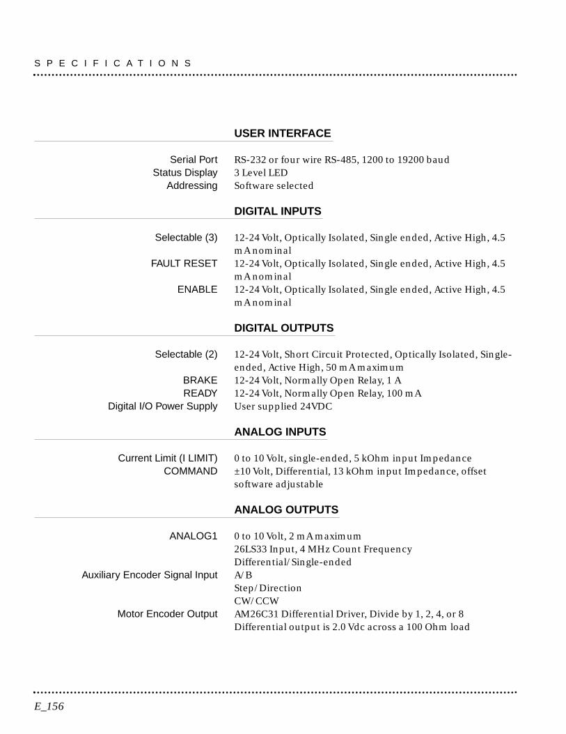
USER INTERFACE
Serial Port RS-232 or four wire RS-485, 1200 to 19200 baud Status Display 3 Level LED
Addressing Software selected
DIGITAL INPUTS
Selectable (3) 12-24 Volt, Optically Isolated, Single ended, Active High, 4.5 mA nominal
FAULT RESET 12-24 Volt, Optically Isolated, Single ended, Active High, 4.5 mA nominal
ENABLE 12-24 Volt, Optically Isolated, Single ended, Active High, 4.5 mA nominal
DIGITAL OUTPUTS
Selectable (2) 12-24 Volt, Short Circuit Protected, Optically Isolated, Single-ended, Active High, 50 mA maximum
BRAKE 12-24 Volt, Normally Open Relay, 1 AREADY 12-24 Volt, Normally Open Relay, 100 mA
Digital I/O Power Supply User supplied 24VDC
ANALOG INPUTS
Current Limit (I LIMIT) 0 to 10 Volt, single-ended, 5 kOhm input ImpedanceCOMMAND ±10 Volt, Differential, 13 kOhm input Impedance, offset
software adjustable
ANALOG OUTPUTS
ANALOG1 0 to 10 Volt, 2 mA maximum26LS33 Input, 4 MHz Count FrequencyDifferential/Single-ended
Auxiliary Encoder Signal Input A/BStep/DirectionCW/CCW
Motor Encoder Output AM26C31 Differential Driver, Divide by 1, 2, 4, or 8Differential output is 2.0 Vdc across a 100 Ohm load
S P E C I F I C A T I O N S
E_156

MEMORY
Parameter Data Retention 20 years
MOTOR PROTECTION
Motor Overload Protection The drive utilizes solid state motor overload protectionwhich operates:• within 8 minutes at 200% overload• within 20 seconds at 600% overload
SPEED REGULATION
Type Digital, PID-3dB Bandwidth 300 Hz-45° Bandwidth 50 Hz
Ripple ±0.44 rpm with 5000 PPR encoderSpeed Range 1:8000 rpm
POSITION REGULATION
Type Digital, PID with Feedforward
FILTERS
Low Pass Digital, 0 - 1000 Hz, -3 dB Bandwidth, Selectable
continued
E_157
S P E C I F I C A T I O N S
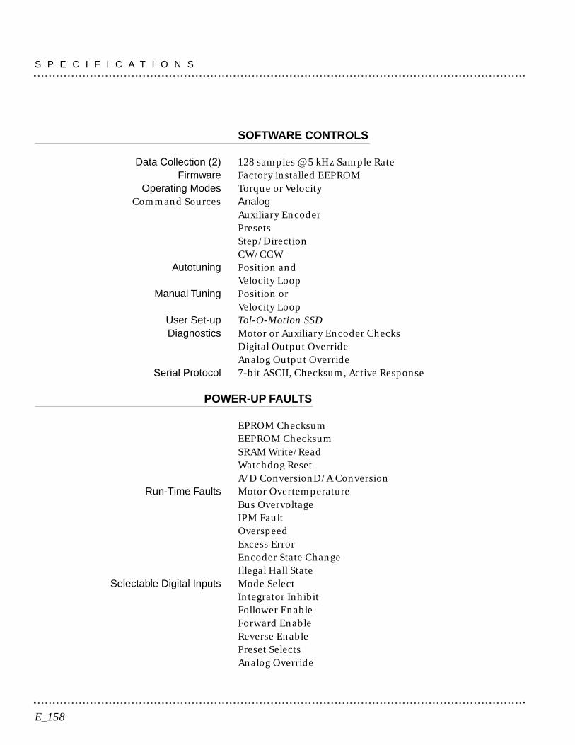
SOFTWARE CONTROLS
Data Collection (2) 128 samples @ 5 kHz Sample RateFirmware Factory installed EEPROM
Operating Modes Torque or VelocityCommand Sources Analog
Auxiliary EncoderPresetsStep/DirectionCW/CCW
Autotuning Position and Velocity Loop
Manual Tuning Position or Velocity Loop
User Set-up Tol-O-Motion SSDDiagnostics Motor or Auxiliary Encoder Checks
Digital Output OverrideAnalog Output Override
Serial Protocol 7-bit ASCII, Checksum, Active Response
POWER-UP FAULTS
EPROM ChecksumEEPROM ChecksumSRAM Write/ReadWatchdog ResetA/D ConversionD/A Conversion
Run-Time Faults Motor OvertemperatureBus OvervoltageIPM FaultOverspeedExcess ErrorEncoder State ChangeIllegal Hall State
Selectable Digital Inputs Mode SelectIntegrator InhibitFollower EnableForward EnableReverse EnablePreset SelectsAnalog Override
S P E C I F I C A T I O N S
E_158

Selectable Digital Outputs In-PositionWithin Position WindowZero SpeedWithin Speed Window± Current LimitUp To SpeedEnabledCharged
SPEED CONTROL COMMAND
Range 0 to ±32,767 RPM (actual maximum speed depends on themotor/drive combination)
E_159
S P E C I F I C A T I O N S

Power
SSD5 SSD10 SSD20AC Input 100-240 VACrms 100 to 240 VACrms 100 to 240 VACrms
Voltage and Frequency nominal nominal nominalSingle Phase Single Phase Single Phase47 - 63 Hz 47 - 63 Hz 47 - 63 Hz
AC Input Current 5 Arms 9 Arms 18 ArmsBus Voltage 141-339 VDC 141-339 VDC 141-339 VDC
Output Peak Current 7.5 Amps 15 Amps 30 AmpsContinuous Output Current (peak) 2.5 Amps 5 Amps 10 Amps
Bus Capacitance Energy Absorption 38 Joules 51 Joules 51 Joules(from 325-400 Vdc Bus)a C=1410uF C=1880uF C=1880uF
Peak Power Outputb 120 Vac 0.9 kWatts 120 Vac 1.3 kWatts 120 Vac 2.7 kWatts240 Vac1.8 kWatts 240 Vac 2.7 kWatts 240 Vac 5.5 kWatts
Continuous Power Output2 120 Vac 0.3 kWatts 120 Vac 0.6 kWatts 120 Vac 1.2 kWatts240 Vac 0.6 kWatts 240 Vac 1.2 kWatts 240 Vac 2.5 kWatts
a. Bus capacitance energy absorption is based on the followingequations:
b. Power outputs are based on the following equation:
kWatts VACIRmax= ×
×
×2
3 0 85.
ε
ε
µ
= ( ) − ( )= ( ) − ( )
⋅ −( ) = ( )= × =
12
12
12
42012
325
12
420 325 35387
17 470 282
2 2
2 2
C V C V
C C
C C
C F E
2f
2i
if ,
S P E C I F I C A T I O N S
E_160

POWER DISSIPATION
The SSD drive dissipates power that results in cabinet heating. Thefollowing table lists power dissipation values. Calculate the cabinetcooling requirements using the power dissipation information andformulae below.
NOTE: These values do not include external shunt regulator power(regenerated power).
Maximum power losses are shown to help size a NEMA 12 or equiv-alent enclosure and to ensure the required ventilation. Typical power lossesare about one-half maximum power losses.
When sizing an enclosure with no active method of heat dissipation,the following equation approximates the size of enclosure necessary:
T = 4.08 * (Q/A) + 1.1
where:T = Temperature difference between inside air and outside ambient (°F)Q = Heat generated in enclosure (watts)A = Enclosure surface area in ft.2 = (2dw + 2dh + 2wh) / 144d = Depth in inchesh = Height in inchesw = Width in inches
E_161
S P E C I F I C A T I O N S
Current as % of RatedContinuous Current
SSD5 SSD10 SSD20
100
NOTE: These values do not include external shunt regulator power (regenerated power)
48 W 48 W 50 W

S P E C I F I C A T I O N S
E_162
The following product warranty and returned goods informationsummarizes the product warranty and return policy of Tol-O-Matic.A copy of the formal Returned Goods and Field Service Policy is avail-able upon request.
Defective Equipment
If the user is unable to correct a problem, and the product is defective,the unit may be returned to any distributor of Tol-O-Matic productsfor repair or replacement.
There are no field serviceable parts in the drive, other than fuses andjumpers. If the drive fails, the unit should be returned to the factoryfor repair or replacement. To save unnecessary work and repaircharges, please verify that the drive unit is defective before returning itfor repair.
SSD drives are warranted against defects in material and assembly.Limitations to warranty coverage are detailed in Returned Goods andField Service Policy. Products that have been modified by thecustomer, physically mishandled, or otherwise abused throughincorrect wiring, inappropriate settings, and so on, are exempt fromthe warranty plan.
Return Procedure
To ensure accurate processing and prompt return of any Tol-O-Maticproduct, the following procedure must be followed:
1. Call the nearest distributor of Tol-O-Matic products to obtain aReturn Material Authorization (RMA) number. Do not return thedrive or any other equipment without a valid RMA number. Returnslacking a valid RMA number will not be accepted and will be returnedto the sender.
2. Pack the drive in the original shipping carton. Tol-O-Matic is notresponsible or liable for damage resulting from improper packagingor shipment.
Repaired units are shipped via UPS Ground delivery. If another methodof shipping is desired, please indicate this when requesting the RMAnumber and include this information with the returned unit.
F_163
WarrantyF

Product Support
Axidyne product support is available over the phone. When you call,you should be at your computer and have the hardware and softwaremanuals at hand. Be prepared to give the following information:
• The version numbers of the hardware and software products.• The type of hardware that you are using.• The fault indicators and the exact wording of any messages
that appears on your screen.• How you have tried to solve the problem.
Distributor & Representative Network
Tol-O-Matic has a wide network of distributors that are trained tosupport our products. If you encounter problems, call the distributoror representative where you purchased the product before contactingthe factory.
Applications Engineers and Field Service
In the United States you can reach the Tol-O-Matic factory based sup-port staff by phone Monday through Friday at 1-800-328-2174. Theapplications engineers can assist you with programming difficulties aswell as ideas for how to approach your automation task. Should yourproblem require on-site assistance, field service is available.
W A R R A N T Y
F_164


TOL-O-MATIC, INC.3800 County Road 116Hamel, MN 55340612.478.8000 Telephone612.478.8080 Faxhttp://www.tolomatic.com
![SGX-SSD: A Policy-based Versioning SSD with Intel SGX · Existing Solution: Versioning SSD[BVSSD, Systor12], [Project Almanac, Eurosys19] §Versioning SSD implements versioning system](https://static.documents.pub/doc/80x56/60ae19522c0a8f54c27ad581/sgx-ssd-a-policy-based-versioning-ssd-with-intel-sgx-existing-solution-versioning.jpg)


![SSD - ESOS LAB€¦ · SSD . 1 SSD Block Diagram 3.2 SSD NAND HDD . . SSD FTL . FTL NAND out-of-place update address mapping . Gabage Collection, Wear-leveling . 4. 4.1 SSD . Disksim[8]](https://static.documents.pub/doc/80x56/5ea6b67696cb1838a26c1ab1/ssd-esos-ssd-1-ssd-block-diagram-32-ssd-nand-hdd-ssd-ftl-ftl-nand-out-of-place.jpg)


