13 - 239 JR EI REPUBLIC OF INDIA THE ASSISTANCE FOR THE INTRODUCTION OF ITS RELATED TO HYDERABAD OUTER RING ROAD CONSTRUCTION PROJECT FINAL REPORT October 2013 JAPAN INTERNATIONAL COOPERATION AGENCY ALMEC CORPORATION EAST NIPPON EXPRESSWAY COMPANY LIMITED Republic of India Hyderabad Growth Corridor Limited
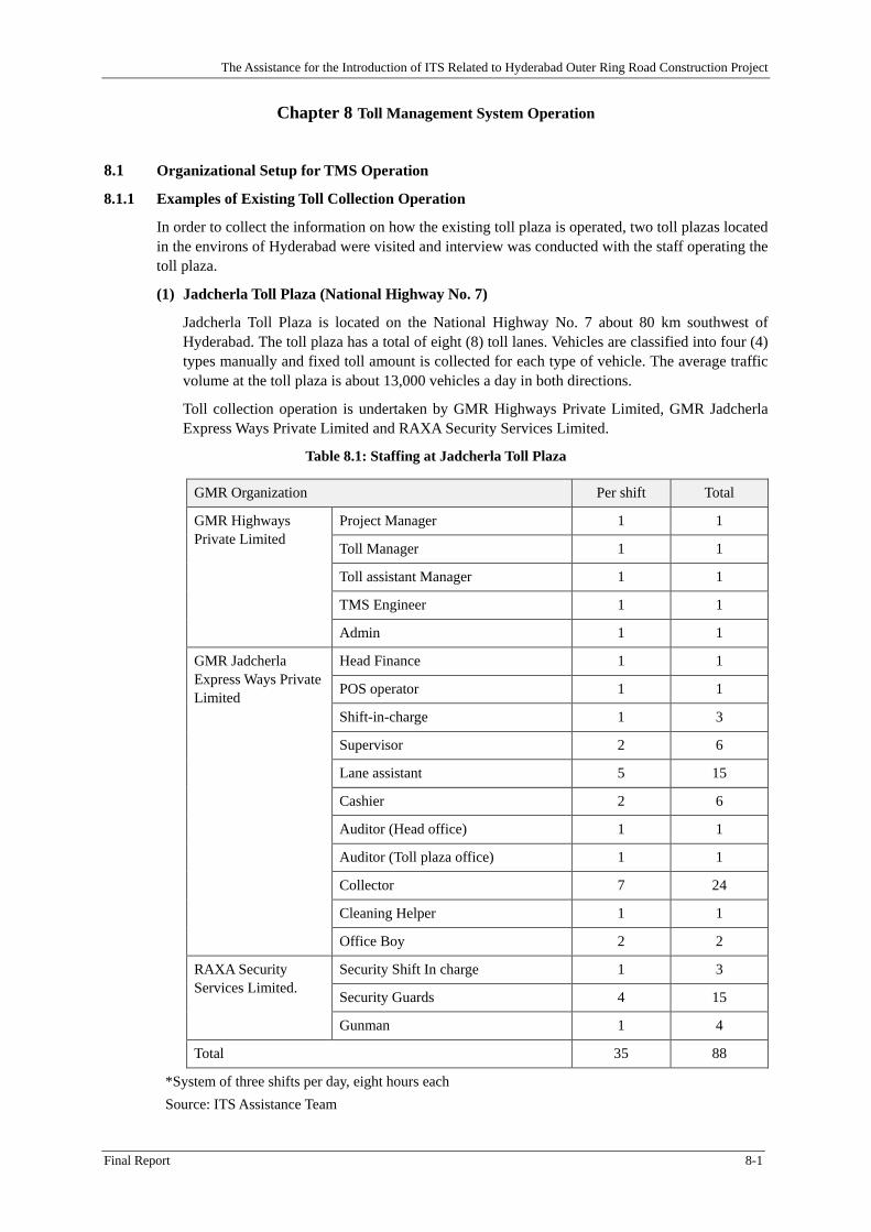
Transcript
RE
PU
BL
IC O
F IN
DIA
TH
E A
SS
ISTA
NC
E F
OR
TH
E IN
TR
OD
UC
TIO
N O
F IT
S R
EL
AT
ED
TO
HY
DE
RA
BA
D O
UT
ER
RIN
G R
OA
D C
ON
ST
RU
CT
ION
PR
OJE
CT
FIN
AL
RE
PO
RT
SU
MM
AR
Y
Octo
ber 2013
RE
PU
BL
IC O
F IN
DIA
T
HE
AS
SIS
TAN
CE
FO
R T
HE
INT
RO
DU
CT
ION
OF
ITS
RE
LA
TE
D T
O H
YD
ER
AB
AD
OU
TE
R R
ING
RO
AD
CO
NS
TR
UC
TIO
N P
RO
JEC
T F
INA
L R
EP
OR
T
Octo
ber 2013
13-239
J R
E I
REPUBLIC OF INDIA
THE ASSISTANCE FOR THE INTRODUCTION OF
ITS RELATED TO HYDERABAD OUTER RING
ROAD CONSTRUCTION PROJECT
FINAL REPORT
October 2013
JAPAN INTERNATIONAL COOPERATION AGENCY
ALMEC CORPORATION
EAST NIPPON EXPRESSWAY COMPANY LIMITED
Republic of India Hyderabad Growth Corridor Limited
RE
PU
BL
IC O
F IN
DIA
TH
E A
SS
ISTA
NC
E F
OR
TH
E IN
TR
OD
UC
TIO
N O
F IT
S R
EL
AT
ED
TO
HY
DE
RA
BA
D O
UT
ER
RIN
G R
OA
D C
ON
ST
RU
CT
ION
PR
OJE
CT
FIN
AL
RE
PO
RT
SU
MM
AR
Y
Octo
ber 2013
RE
PU
BL
IC O
F IN
DIA
T
HE
AS
SIS
TAN
CE
FO
R T
HE
INT
RO
DU
CT
ION
OF
ITS
RE
LA
TE
D T
O H
YD
ER
AB
AD
OU
TE
R R
ING
RO
AD
CO
NS
TR
UC
TIO
N P
RO
JEC
T F
INA
L R
EP
OR
T
Octo
ber 2013
REPUBLIC OF INDIA
THE ASSISTANCE FOR THE INTRODUCTION OF
ITS RELATED TO HYDERABAD OUTER RING
ROAD CONSTRUCTION PROJECT
FINAL REPORT
October 2013
JAPAN INTERNATIONAL COOPERATION AGENCY
ALMEC CORPORATION
EAST NIPPON EXPRESSWAY COMPANY LIMITED
Republic of India Hyderabad Growth Corridor Limited
1.2 Objectives of the Project ............................................................................................................... 1-1
1.3 Project Area ................................................................................................................................... 1-2
1.4 Scope of Works ............................................................................................................................. 1-3
1.5 Project Implementation Arrangements and Milestones ................................................................. 1-4 1.5.1 ITS Assistance Team ..................................................................................................................... 1-4 1.5.2 Counterpart .................................................................................................................................... 1-5 1.5.3 Implementation Schedule and Milestones ..................................................................................... 1-5
CHAPTER 2 ITS IN INDIA ............................................................................................................. 2-1
2.1 Overview of ITS in India .............................................................................................................. 2-1 2.1.1 Introduction ................................................................................................................................... 2-1 2.1.2 Background ................................................................................................................................... 2-1 2.1.3 ITS Components to be introduced ................................................................................................. 2-1
2.2 Preceding Operational Examples of ETC in India ........................................................................ 2-1 2.2.1 Delhi Gurgaon Expressway ........................................................................................................... 2-1 2.2.2 Delhi Noida Direct Flyway ........................................................................................................... 2-3 2.2.3 Mumbai - Pune Expressway .......................................................................................................... 2-4 2.2.4 ETC Pilot Projects by Ministry of Road Transport and Highways ............................................... 2-6 2.2.5 ETC Committee and its Report ..................................................................................................... 2-7
2.3 Promotion of ETC in India ............................................................................................................ 2-9 2.3.1 Overall Discussions ....................................................................................................................... 2-9 2.3.2 Promotion of ETC (1): ETC Trial Operations for Users ............................................................... 2-9 2.3.3 Promotion of ETC (2): the best practice is the fare discount for ETC users ................................. 2-9 2.3.4 Discount service and Data Configuration of the Smart card ....................................................... 2-10
CHAPTER 4 TOLL MANAGEMENT SYSTEM ........................................................................... 4-1
4.1 Outline of system .......................................................................................................................... 4-1
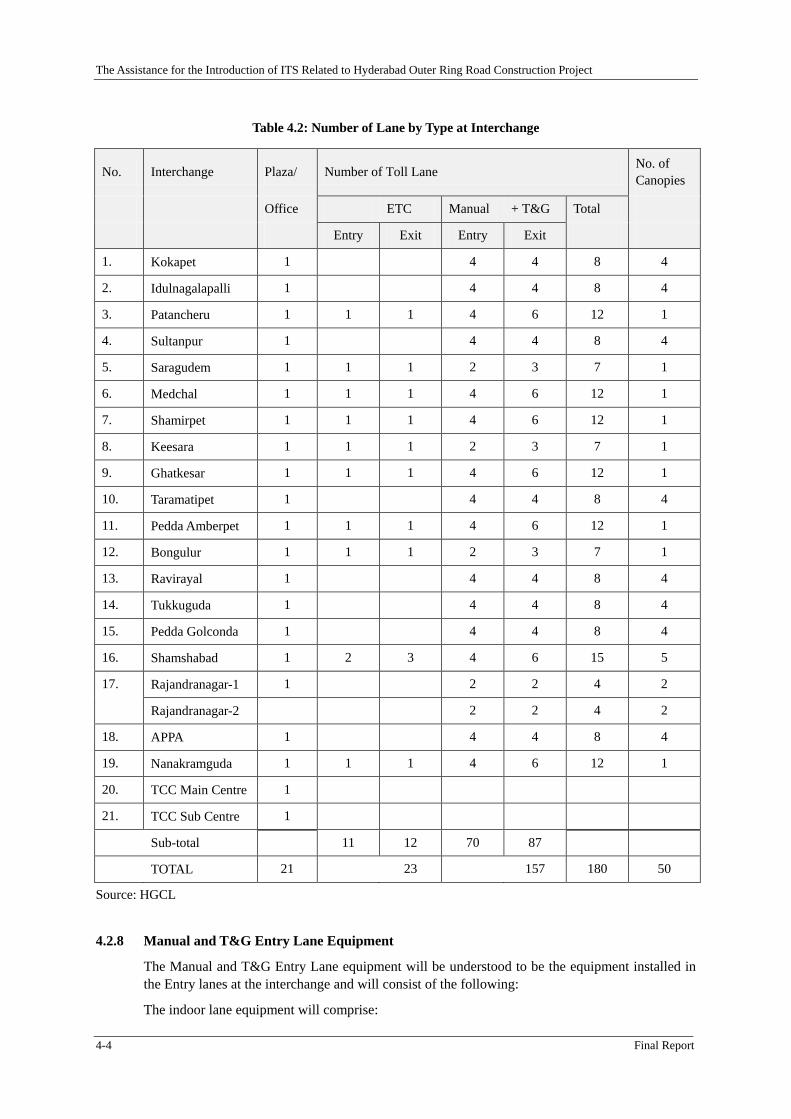
4.2 Design Policy and System Configuration ..................................................................................... 4-1 4.2.1 Vehicle Classification and Toll Fare .............................................................................................. 4-1 4.2.2 Cards used with the System .......................................................................................................... 4-2 4.2.3 Code system .................................................................................................................................. 4-2 4.2.4 Transaction .................................................................................................................................... 4-2 4.2.5 Toll collection facilities ................................................................................................................. 4-3 4.2.6 Staff ID .......................................................................................................................................... 4-3 4.2.7 System Components ...................................................................................................................... 4-3 4.2.8 Manual and T&G Entry Lane Equipment ..................................................................................... 4-4 4.2.9 Manual and T&G Exit Lane Equipment ....................................................................................... 4-5 4.2.10 ETC Lane Equipment .................................................................................................................... 4-6 4.2.11 Plaza Computer System ................................................................................................................ 4-7 4.2.12 Traffic Control Centre System ...................................................................................................... 4-8 4.2.13 Software ........................................................................................................................................ 4-9 4.2.14 Network Equipment ...................................................................................................................... 4-9 4.2.15 Power Supply ................................................................................................................................ 4-9 4.2.16 Booth Communication System ...................................................................................................... 4-9 4.2.17 CCTV System ............................................................................................................................. 4-10
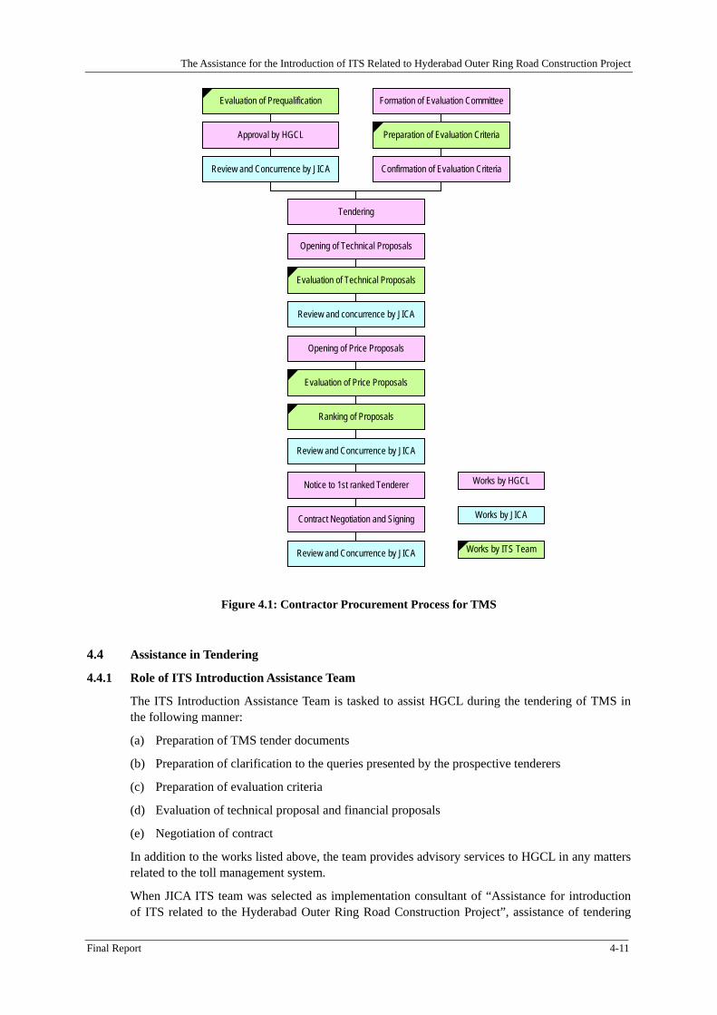
4.4 Assistance in Tendering............................................................................................................... 4-11 4.4.1 Role of ITS Introduction Assistance Team .................................................................................. 4-11
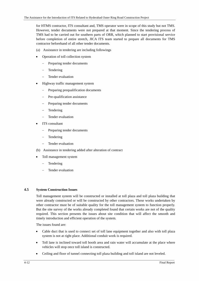
4.5 System Construction Issues ......................................................................................................... 4-12
CHAPTER 5 HIGHWAY TRAFFIC MANAGEMENT SYSTEM ............................................... 5-1
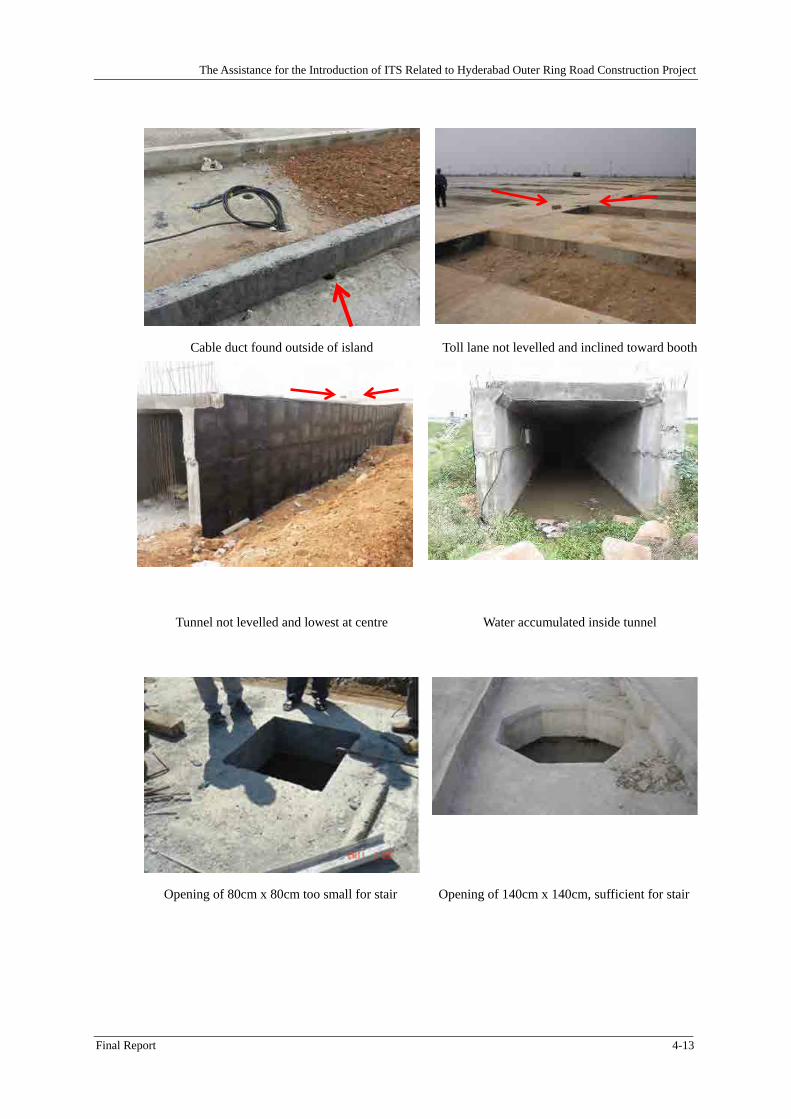
5.1 General .......................................................................................................................................... 5-1
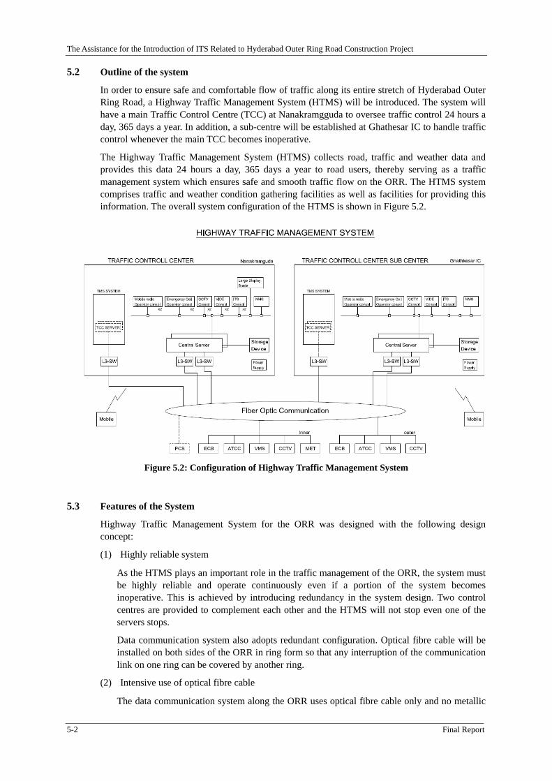
5.2 Outline of the system .................................................................................................................... 5-2
5.3 Features of the System .................................................................................................................. 5-2
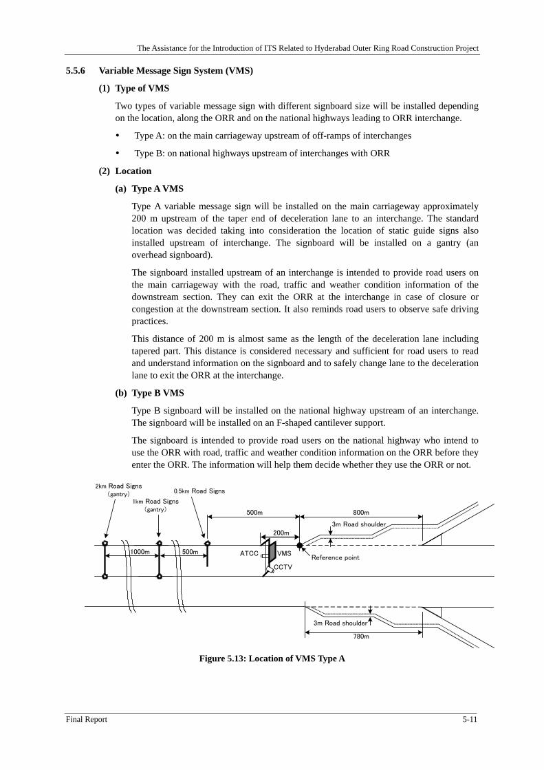
5.5 Design Approach and Principle ..................................................................................................... 5-5 5.5.1 Central Server System ................................................................................................................... 5-5 5.5.2 Emergency Call Box (ECB) .......................................................................................................... 5-7 5.5.3 Closed Circuit Television (CCTV) Camera System ...................................................................... 5-7 5.5.4 Automatic Traffic Counter cum Classifier System ....................................................................... 5-8 5.5.5 Meteorological Observation System (MET) ................................................................................. 5-9 5.5.6 Variable Message Sign System (VMS) ....................................................................................... 5-11 5.5.7 Digital Transmission System (DTS) ........................................................................................... 5-12 5.5.8 Fibre Optic Cable System ........................................................................................................... 5-13
iii
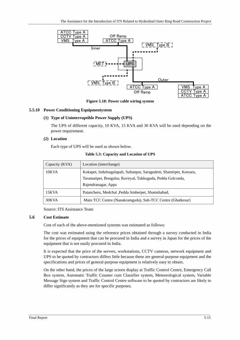
5.5.9 Power and Other Cables .............................................................................................................. 5-14 5.5.10 Power Conditioning Equipmentystem......................................................................................... 5-15
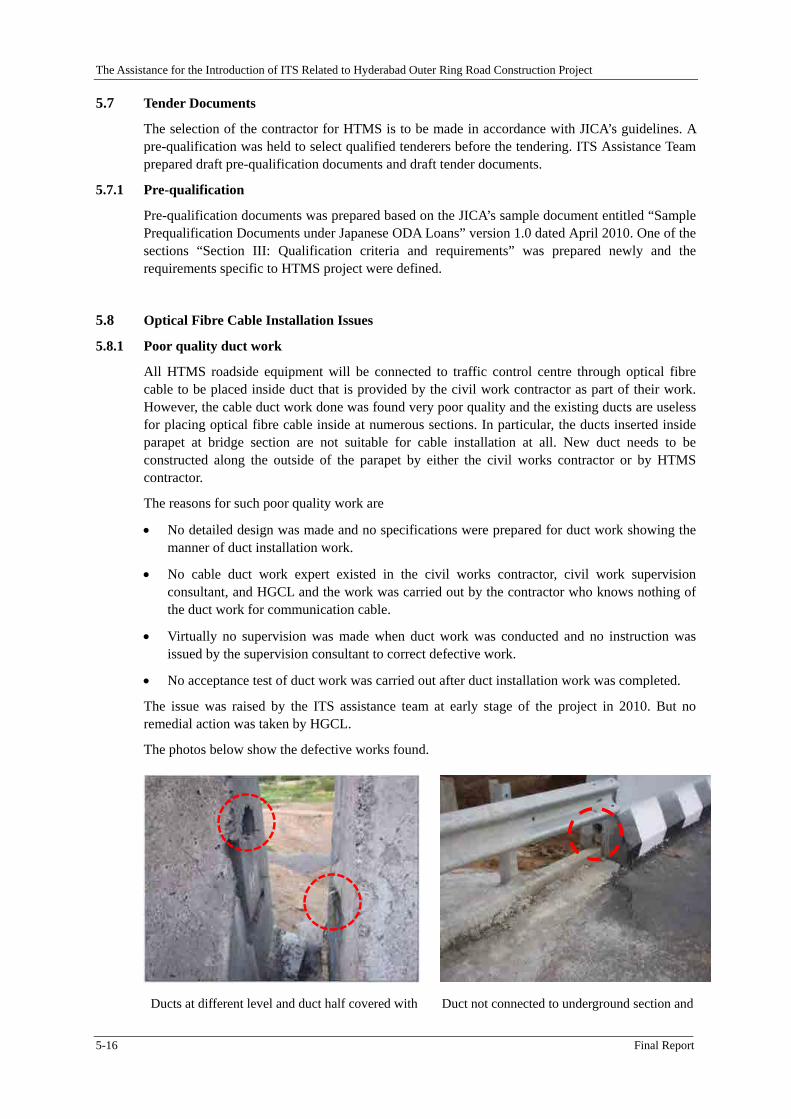
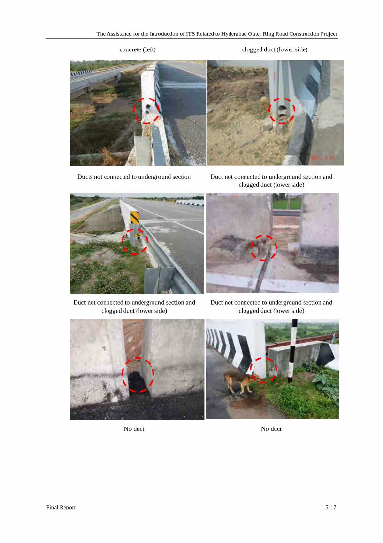
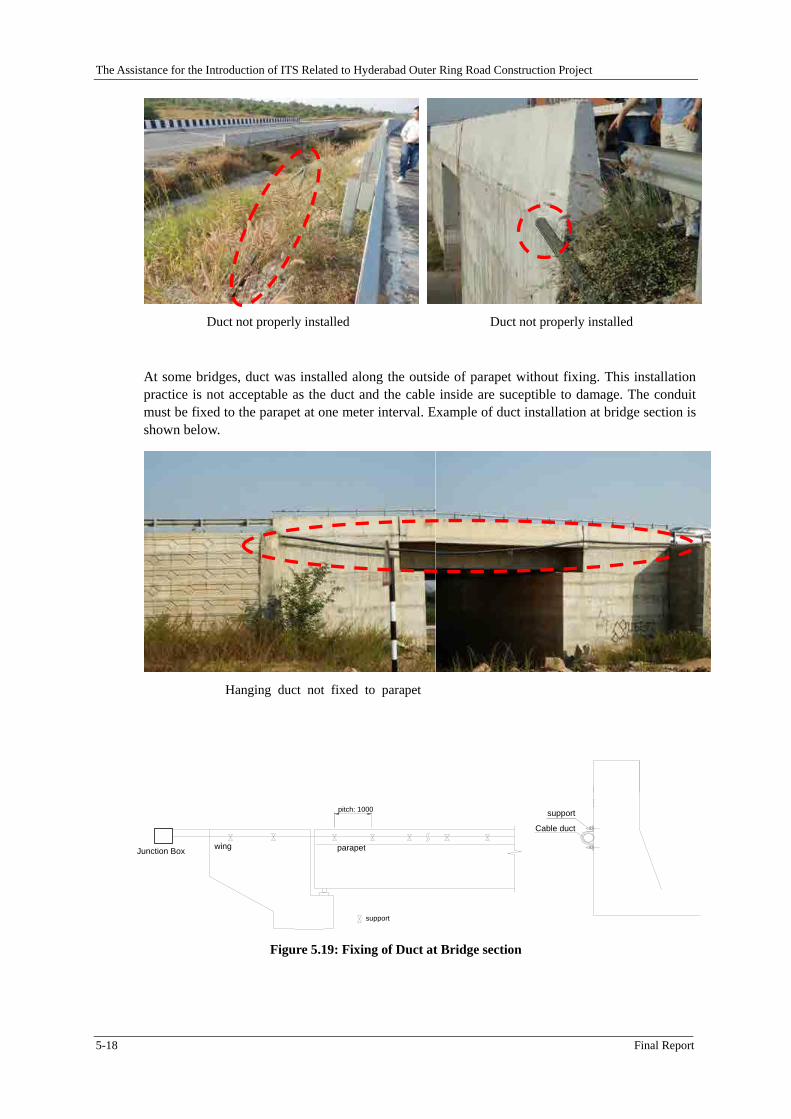
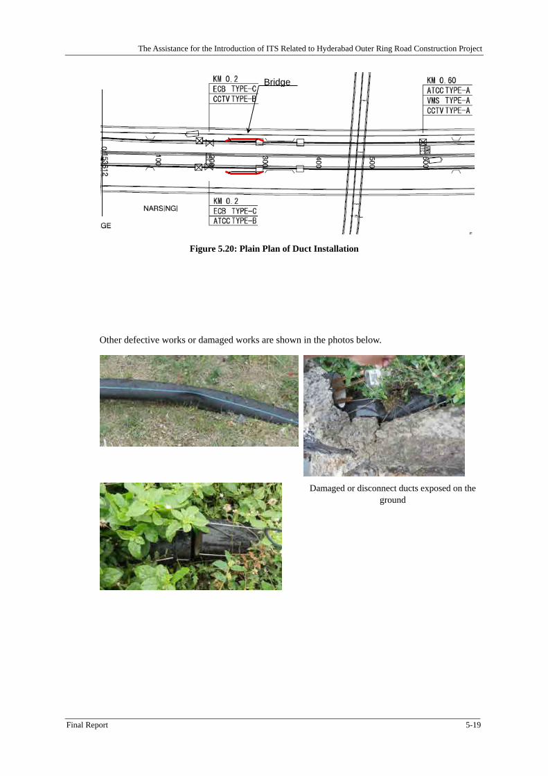
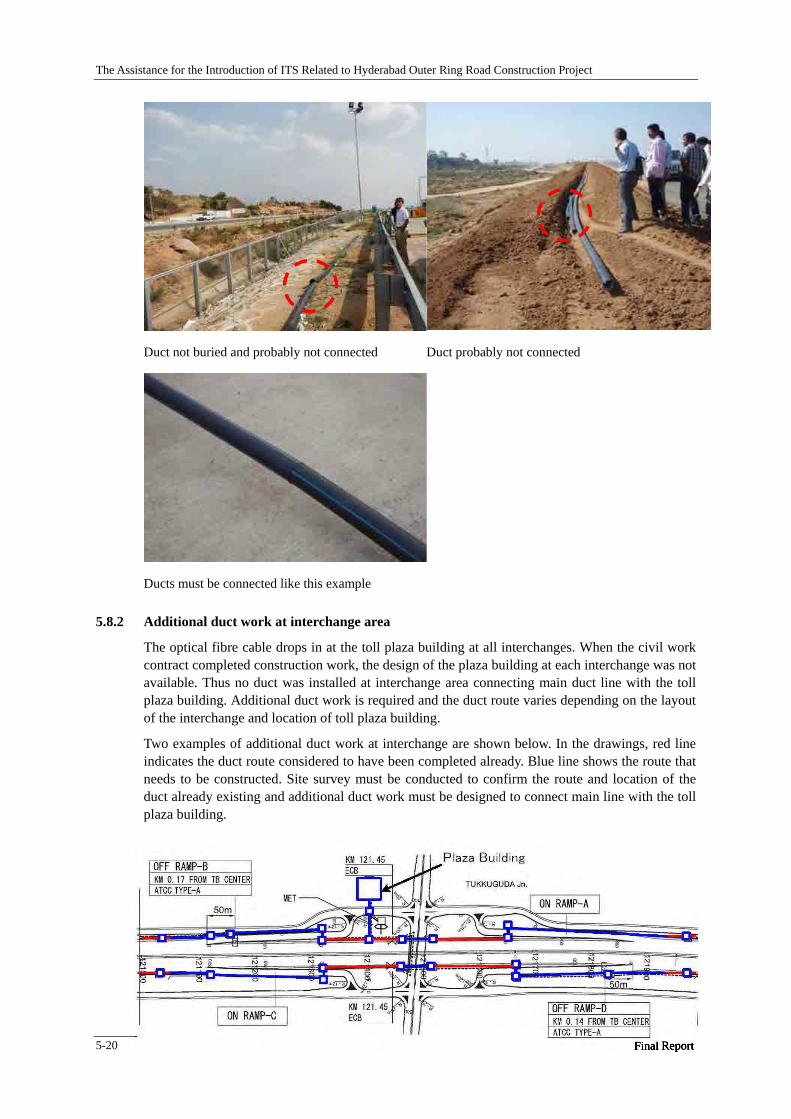
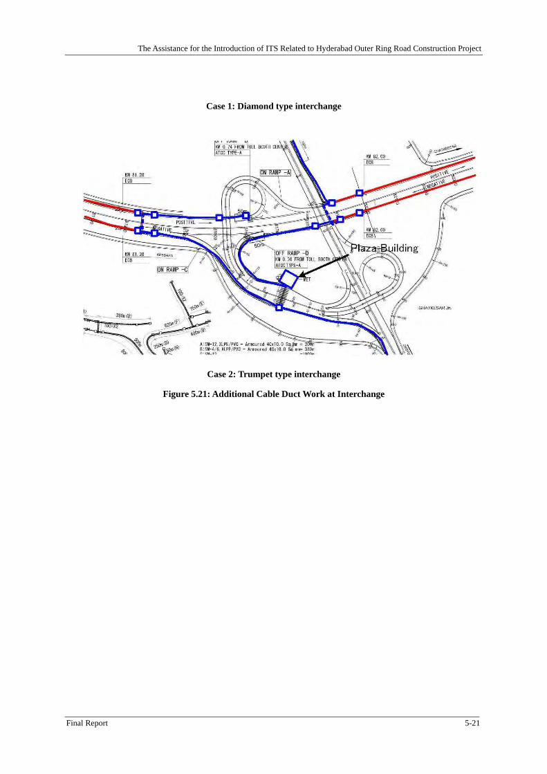
5.8 Optical Fibre Cable Installation Issues ........................................................................................ 5-16 5.8.1 Poor quality duct work ................................................................................................................ 5-16 5.8.2 Additional duct work at interchange area .................................................................................... 5-20
CHAPTER 6 ITS CONSTRUCTION SUPERVISION CONSULTANT ...................................... 6-1
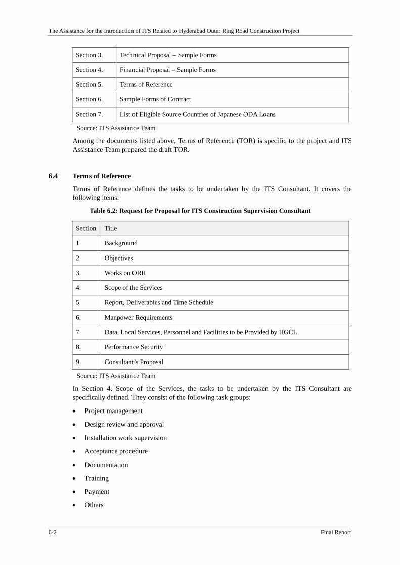
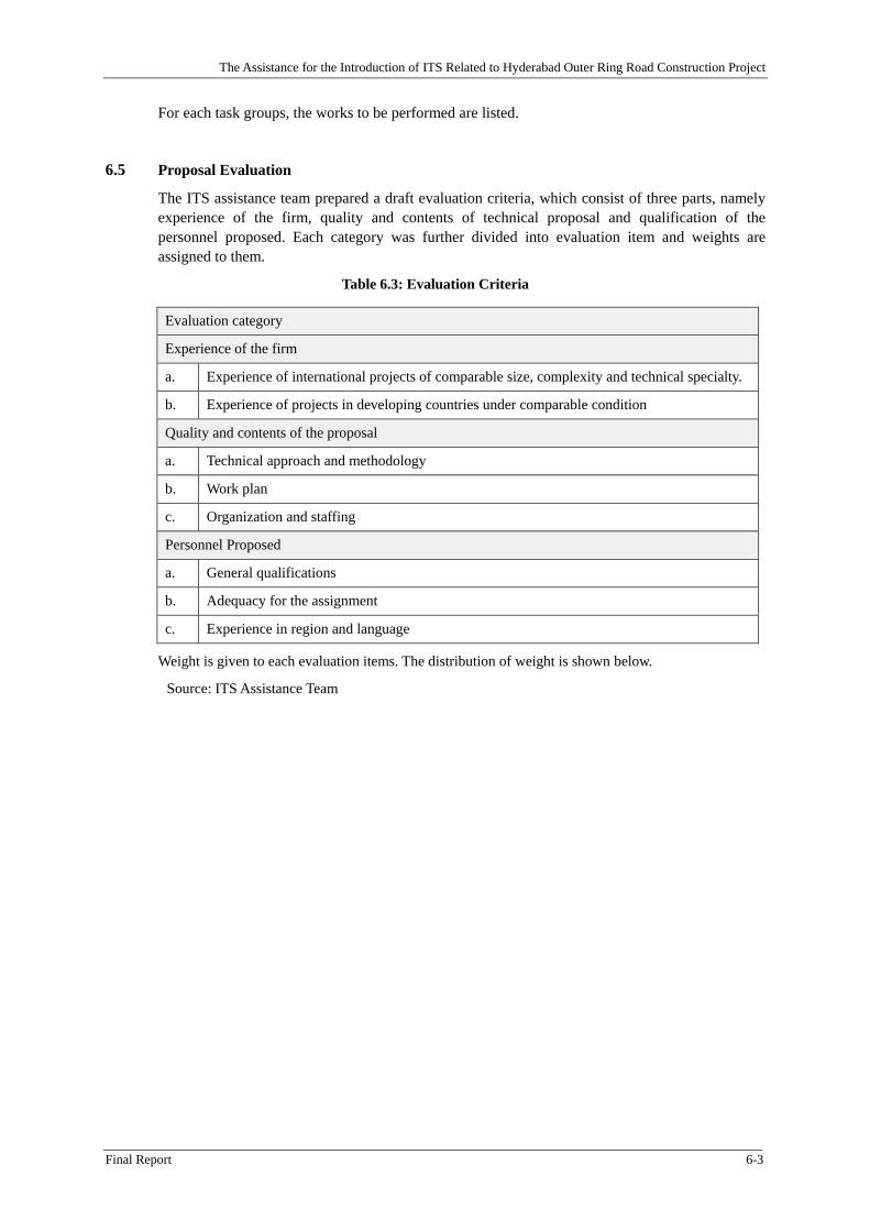
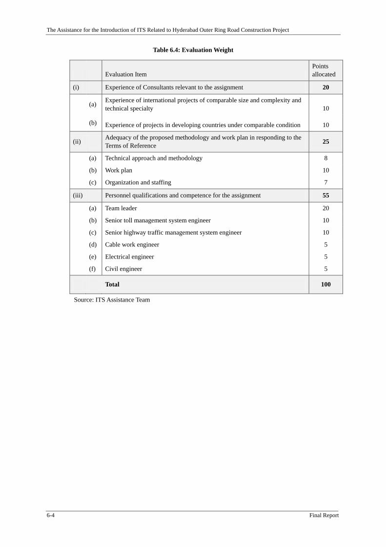
6.1 General .......................................................................................................................................... 6-1
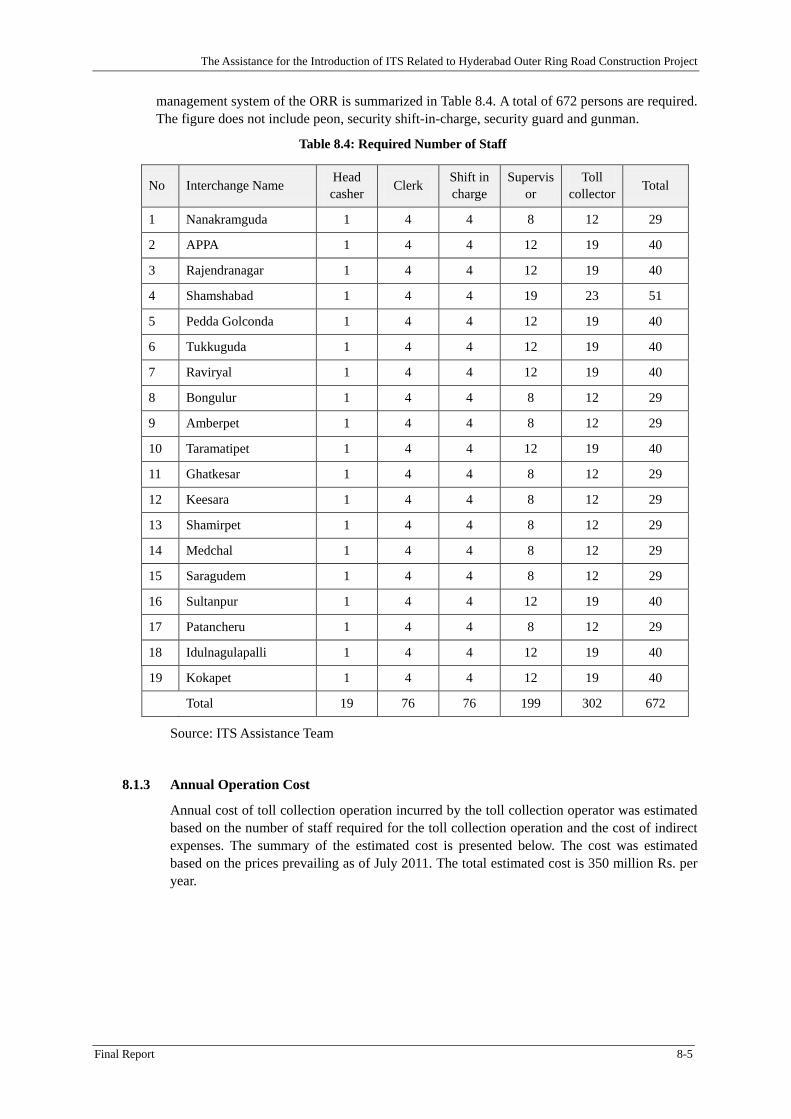
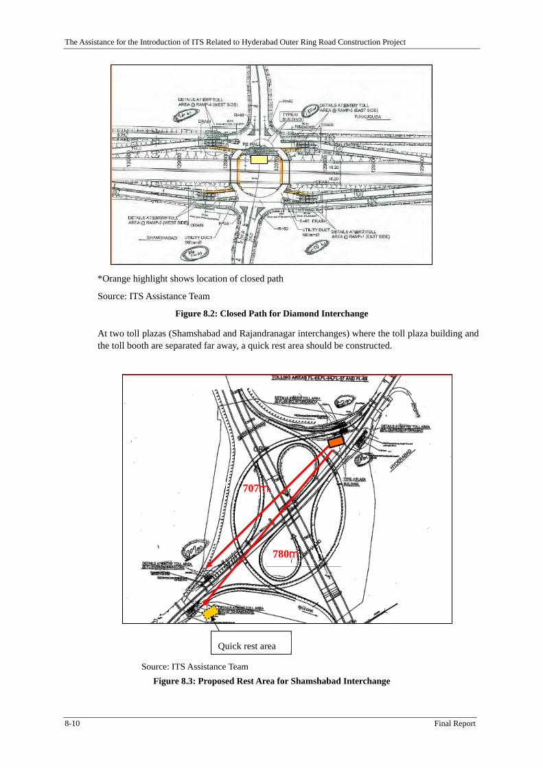
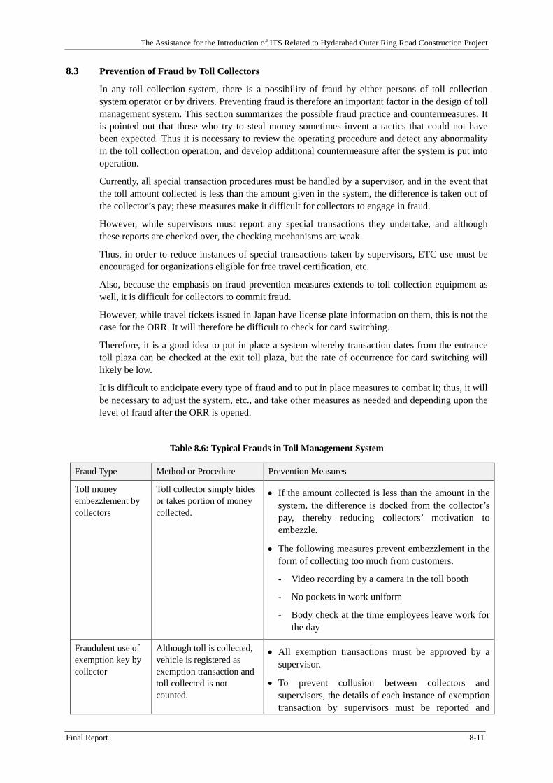
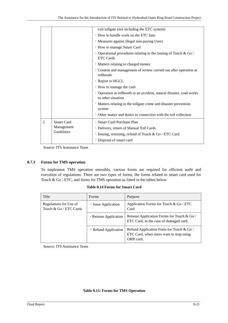
8.2 Deployment plan for each type of interchange ............................................................................. 8-8 8.2.1 Deployment plan by interchange type ........................................................................................... 8-8 8.2.2 Supporting Facilities ..................................................................................................................... 8-9
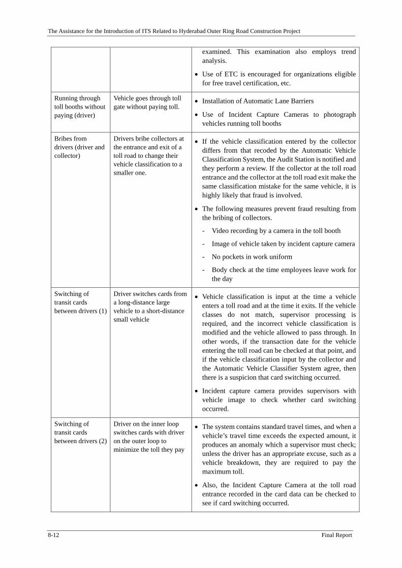
8.3 Prevention of Fraud by Toll Collectors ....................................................................................... 8-11
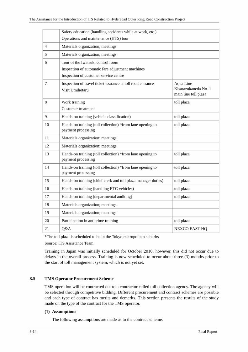
8.4 Training Program ........................................................................................................................ 8-13
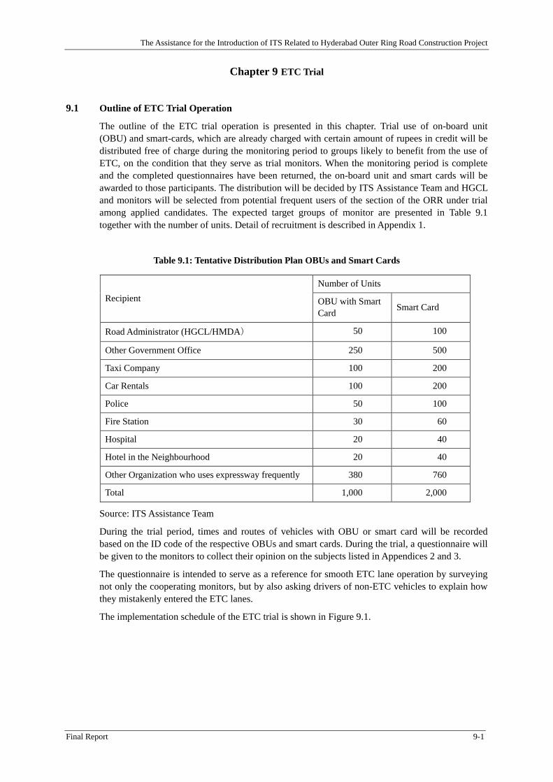
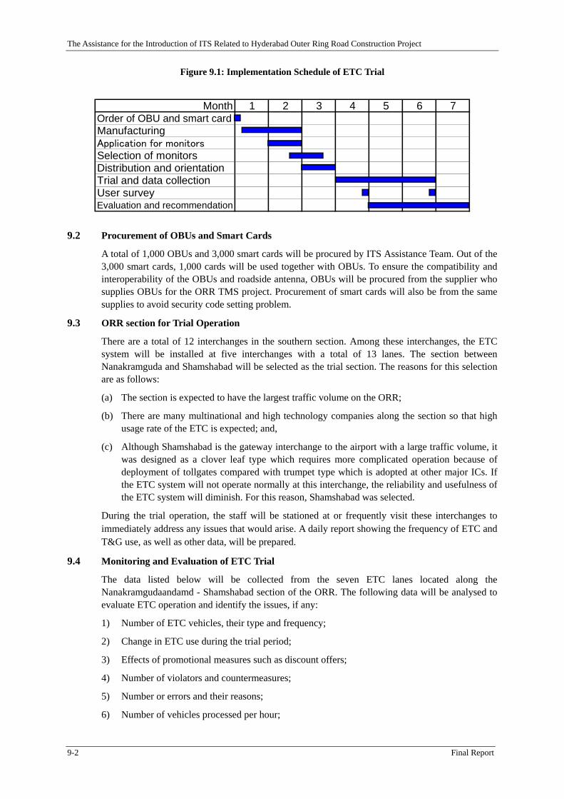
9.7 Selection and Notification ............................................................................................................. 9-3
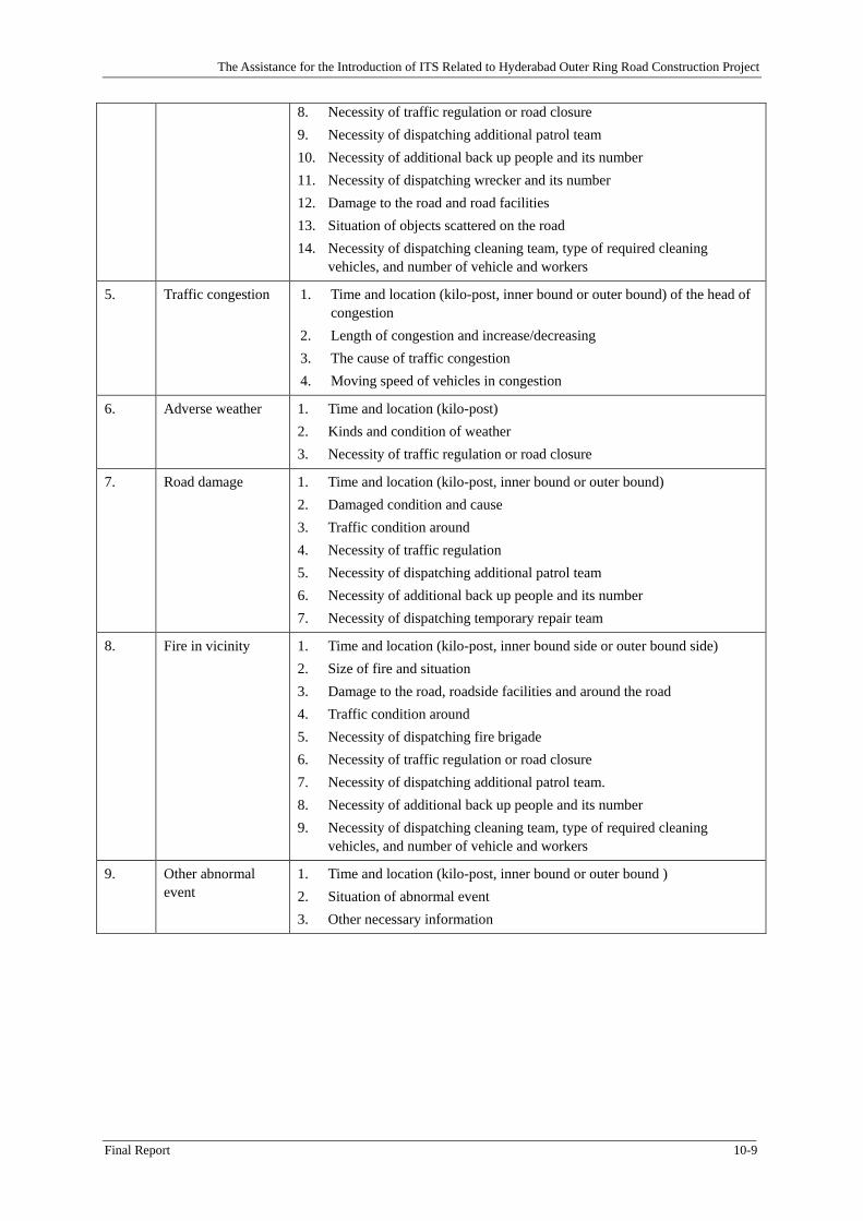
CHAPTER 10 HIGHWAY TRAFFIC MANAGEMENT SYSTEM OPERATION .................. 10-1
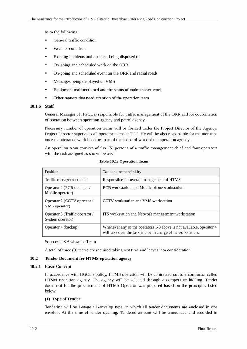
10.1 Organizational Setup for HTMS Operation ................................................................................ 10-1 10.1.1 Scope of works ............................................................................................................................ 10-1 10.1.2 Information to be collected ......................................................................................................... 10-1 10.1.3 Close coordination with other organizations ............................................................................... 10-1 10.1.4 Proposed Organization and shift ................................................................................................. 10-1 10.1.5 Briefing at shift change ............................................................................................................... 10-1 10.1.6 Staff ............................................................................................................................................. 10-2
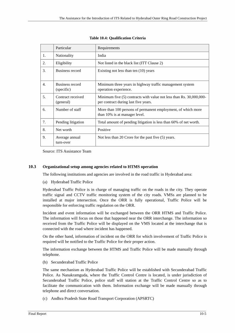
10.3 Organizational setup among agencies related to HTMS operation ............................................. 10-5
10.4 Information Exchange with City ITS .......................................................................................... 10-6 10.4.1 Purpose of information exchange ................................................................................................ 10-6 10.4.2 Information to be provided to City ITS ....................................................................................... 10-6
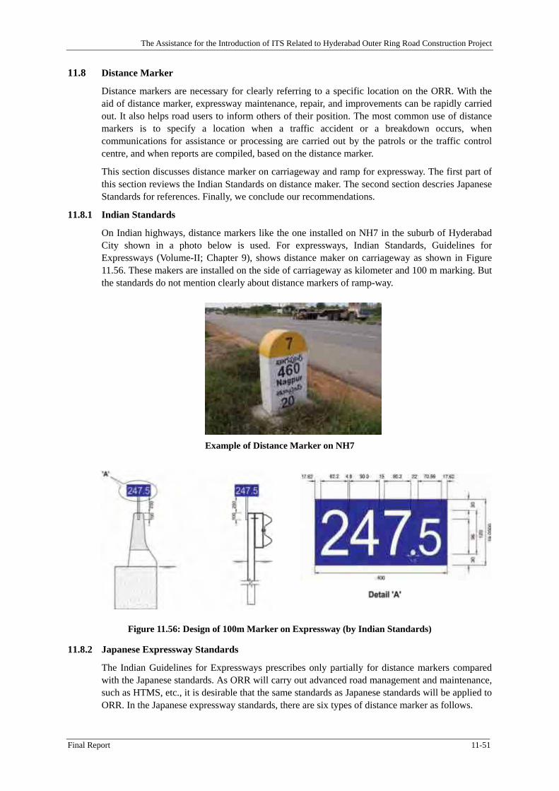
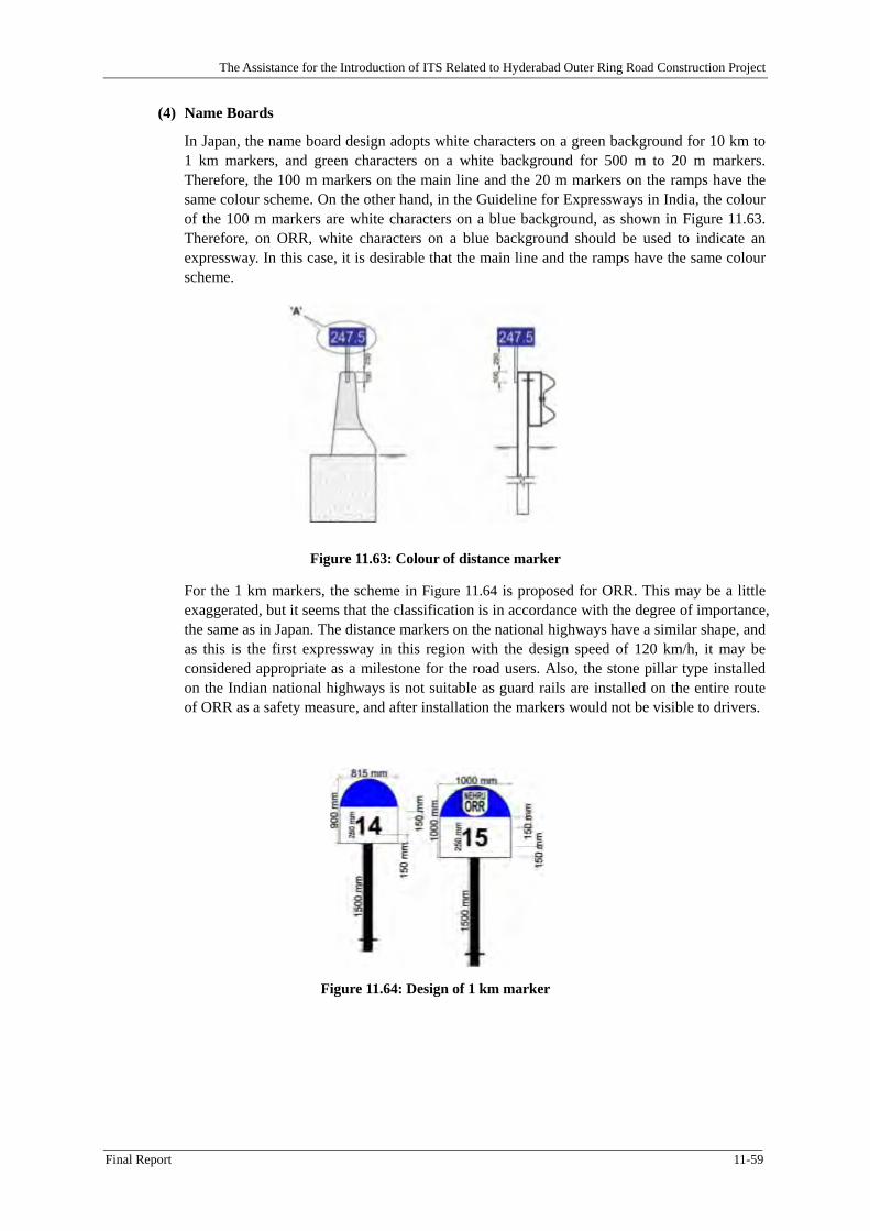
11.1 General ........................................................................................................................................ 11-1
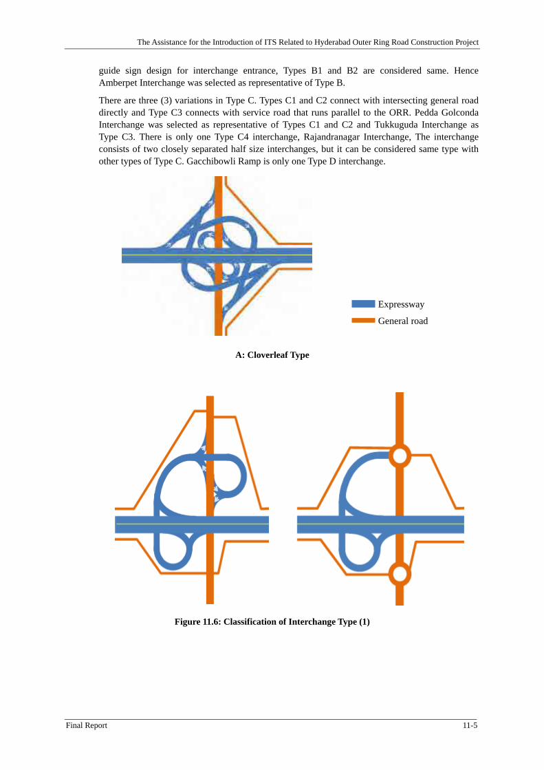
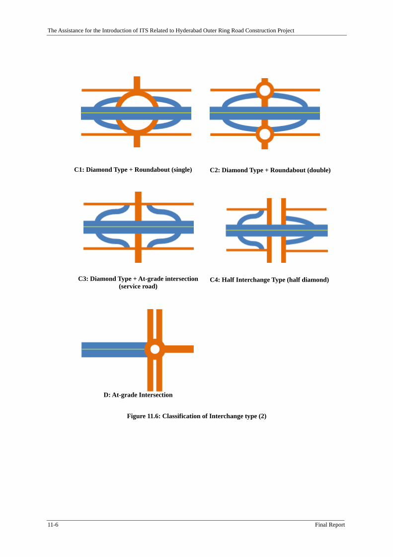
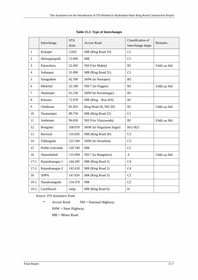
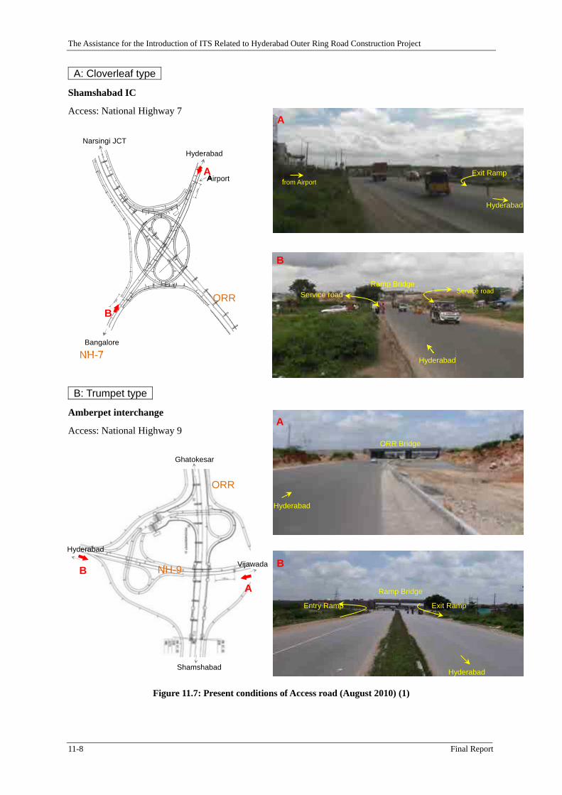
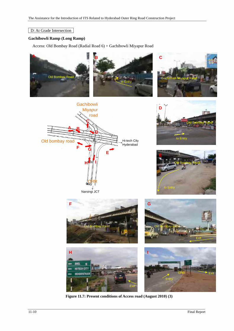
11.2 Guide Traffic Sign on Access Road (Interchange Entrance) ....................................................... 11-1 11.2.1 Indian Standards .......................................................................................................................... 11-1 11.2.2 Japanese Expressway Standards .................................................................................................. 11-3 11.2.3 Interchange Type ......................................................................................................................... 11-4 11.2.4 Recommendation ........................................................................................................................ 11-11
11.3 Guide Traffic Sign on Expressway for Exit at Interchange ....................................................... 11-17 11.3.1 Indian Standards ........................................................................................................................ 11-17 11.3.2 Japanese Expressway Standards ................................................................................................ 11-19 11.3.3 Recommendation ....................................................................................................................... 11-23
11.4 Guide Traffic Sign for Toll Plaza .............................................................................................. 11-28 11.4.1 Indian Standards ........................................................................................................................ 11-28 11.4.2 Japanese Expressway Standards ................................................................................................ 11-29 11.4.3 Recommendation ....................................................................................................................... 11-32
11.5 Sign for Exclusive Motor Vehicle Way ..................................................................................... 11-34 11.5.1 Exclusive motorway .................................................................................................................. 11-34
v
11.5.2 Cabinet Order on Vehicle Restriction ........................................................................................ 11-35 11.5.3 Safety Cushions ......................................................................................................................... 11-35
11.6 Interchange Name Sign and Signs at Toll Plaza ........................................................................ 11-36 11.6.1 Naming of Access Points and Other Locations ......................................................................... 11-37 11.6.2 Indian Standards and Practice ................................................................................................... 11-41 11.6.3 Japanese Standards and Practice ............................................................................................... 11-41 11.6.4 Recommendation ....................................................................................................................... 11-42
11.7 Guide Traffic Sign for ETC ....................................................................................................... 11-42 11.7.1 Indian Standards ........................................................................................................................ 11-42 11.7.2 Japanese Expressway Standards ................................................................................................ 11-43 11.7.3 Recommendation ....................................................................................................................... 11-46
11.8 Distance Marker ........................................................................................................................ 11-51 11.8.1 Indian Standards ........................................................................................................................ 11-51 11.8.2 Japanese Expressway Standards ................................................................................................ 11-51 11.8.3 Recommendation ....................................................................................................................... 11-56
CHAPTER 12 CONCLUSION AND RECOMMENDATIONS .................................................. 12-1
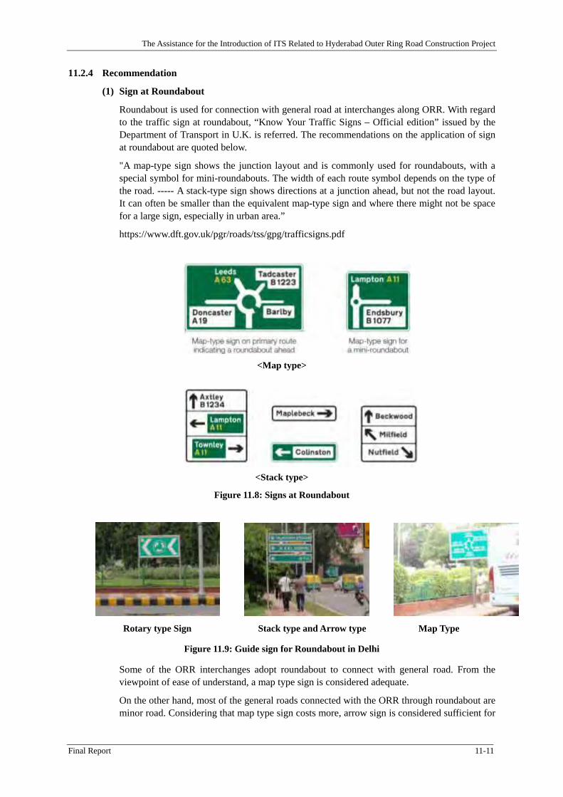
Figure 11.8: Signs at Roundabout .................................................................................................... 11-11
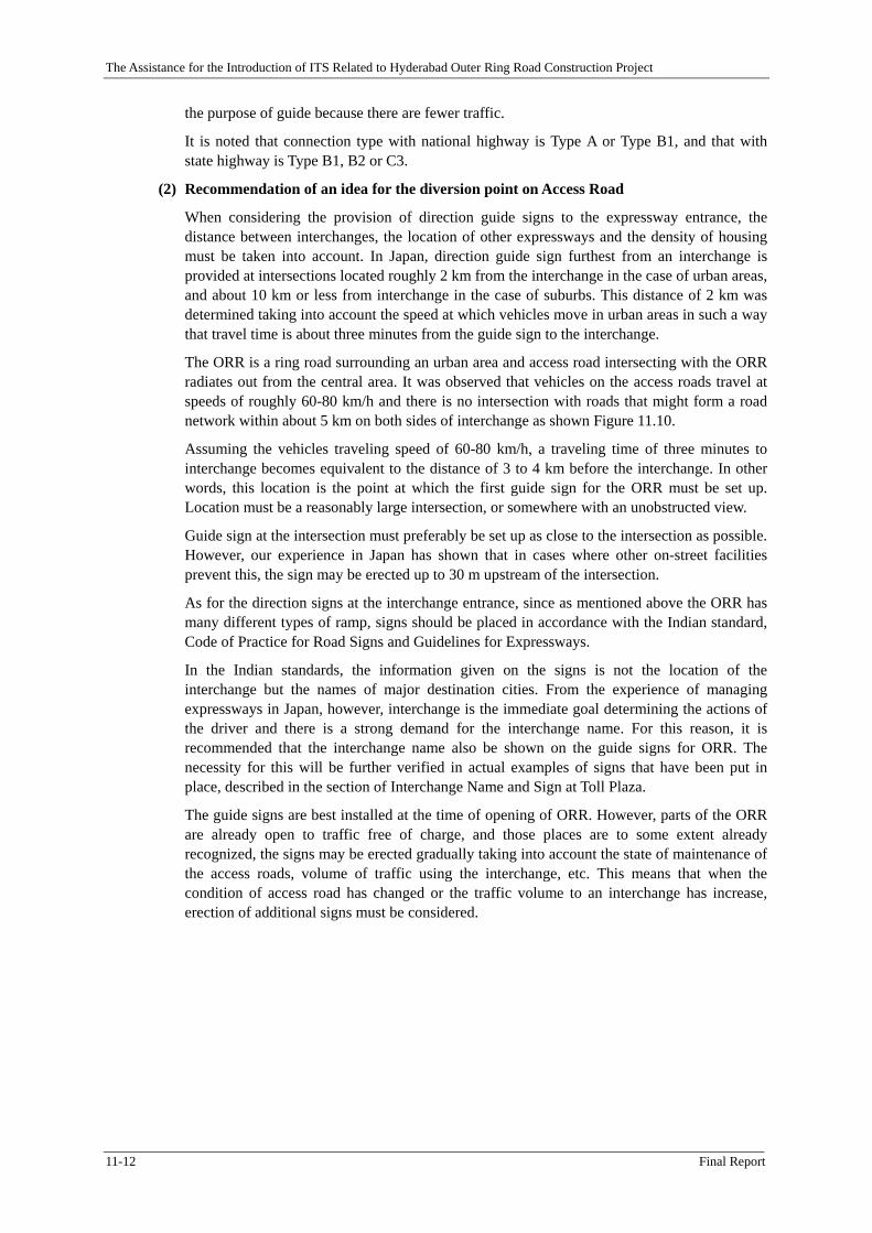
Figure 11.9: Guide sign for Roundabout in Delhi ............................................................................ 11-11
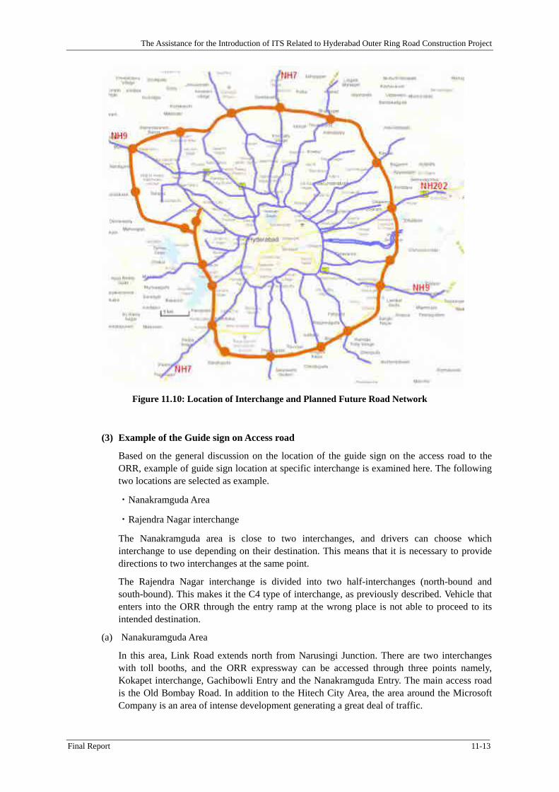
Figure 11.10: Location of Interchange and Planned Future Road Network .................................... 11-13
Figure 11.11: Guide traffic signs on access road for Nanakramguda area ...................................... 11-14
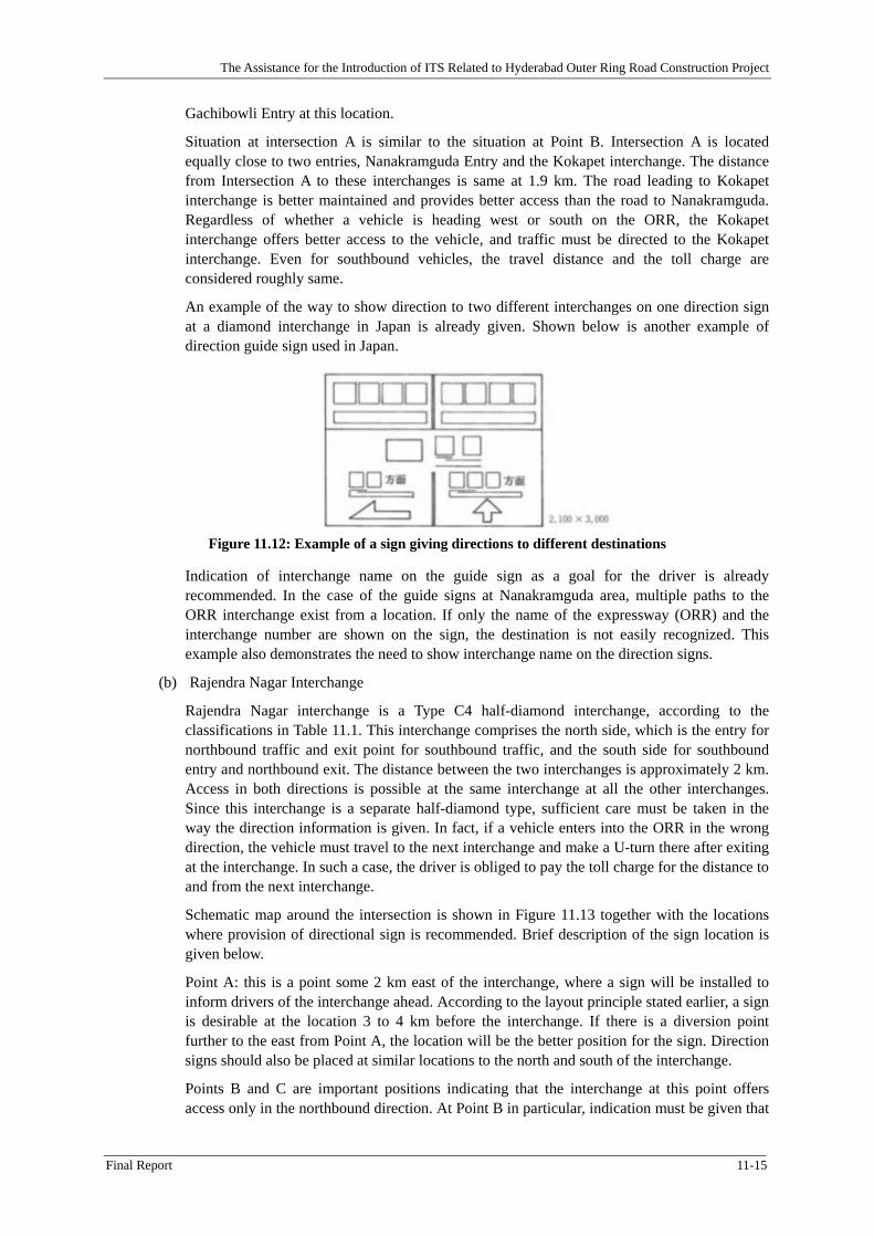
Figure 11.12: Example of a sign giving directions to different destinations ................................... 11-15
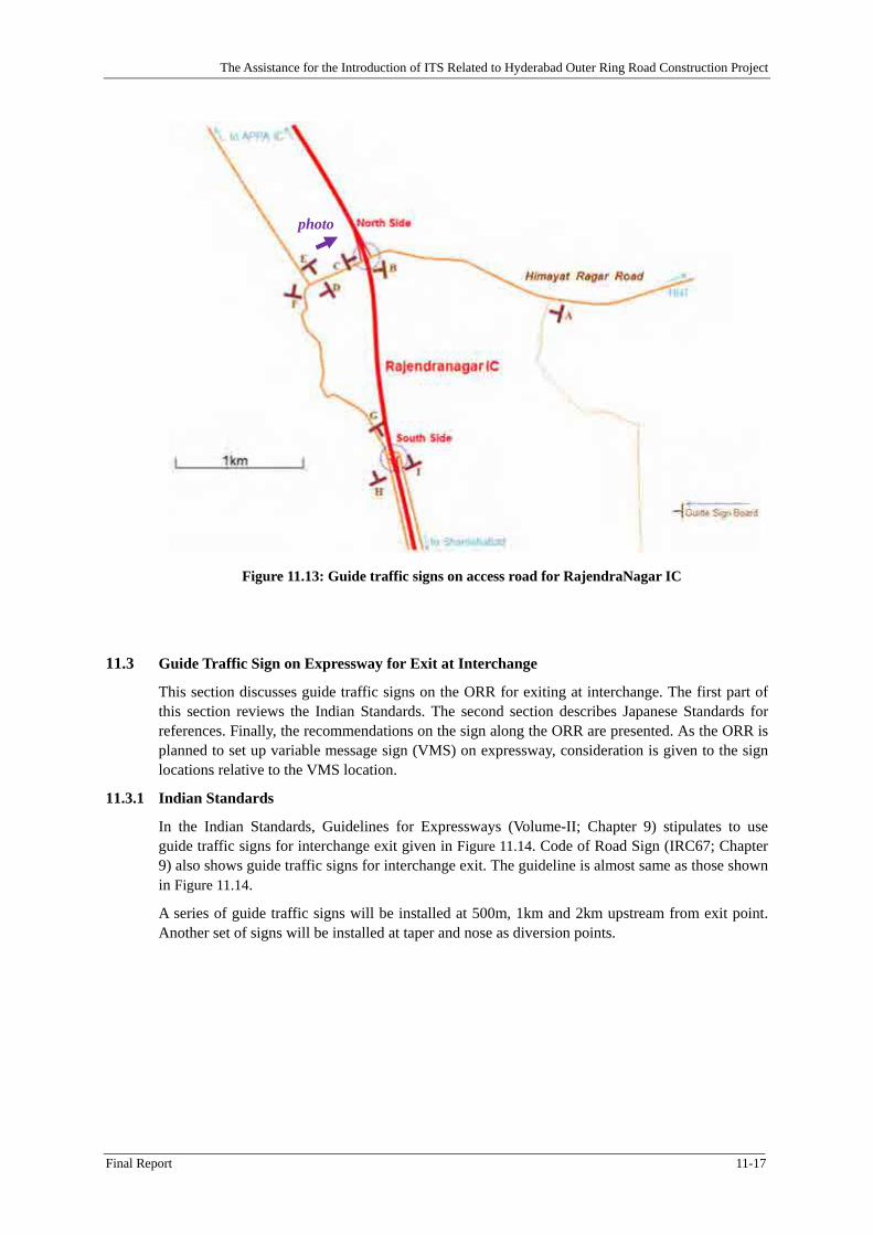
Figure 11.13: Guide traffic signs on access road for RajendraNagar IC ......................................... 11-17
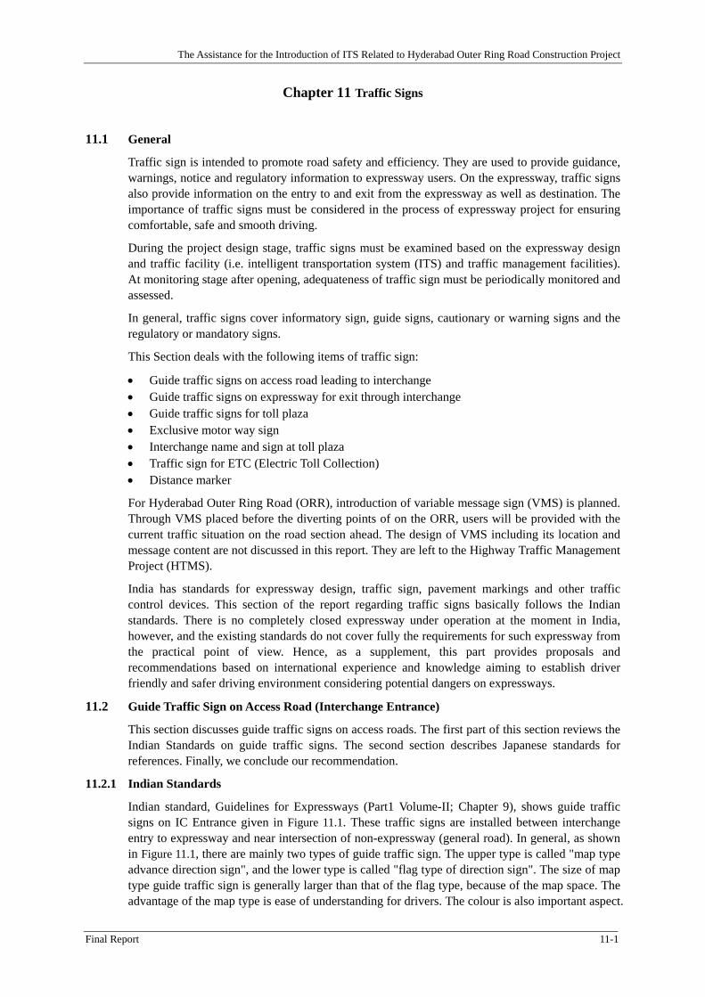
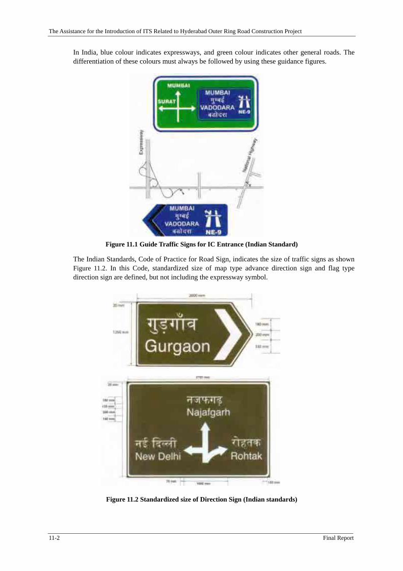
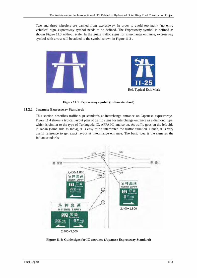
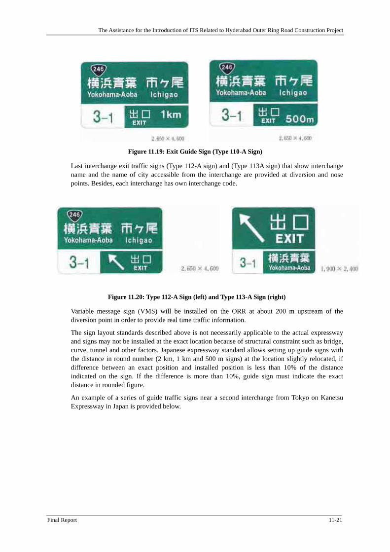
Figure 11.14: Example of Guide Traffic Sign for interchange Exit on Expressway (Indian Standards) ................................................................................................................................................ 11-18
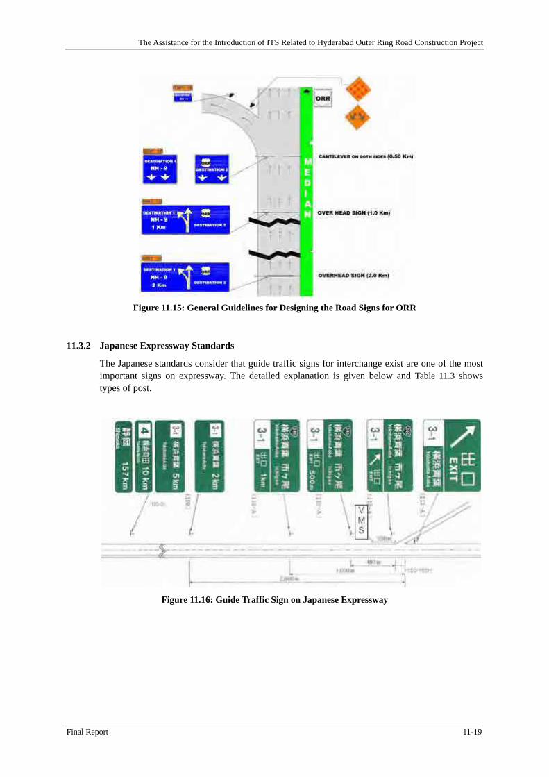
Figure 11.15: General Guidelines for Designing the Road Signs for ORR .................................... 11-19
Figure 11.16: Guide Traffic Sign on Japanese Expressway ............................................................ 11-19
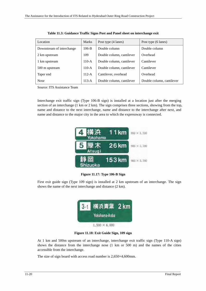
Figure 11.17: Type 106-B Sign ....................................................................................................... 11-20
Figure 11.20: Type 112-A Sign (left) and Type 113-A Sign (right) ................................................ 11-21
Figure 11.21: Example of Series of Guide Traffic Signs in Japan .................................................. 11-22
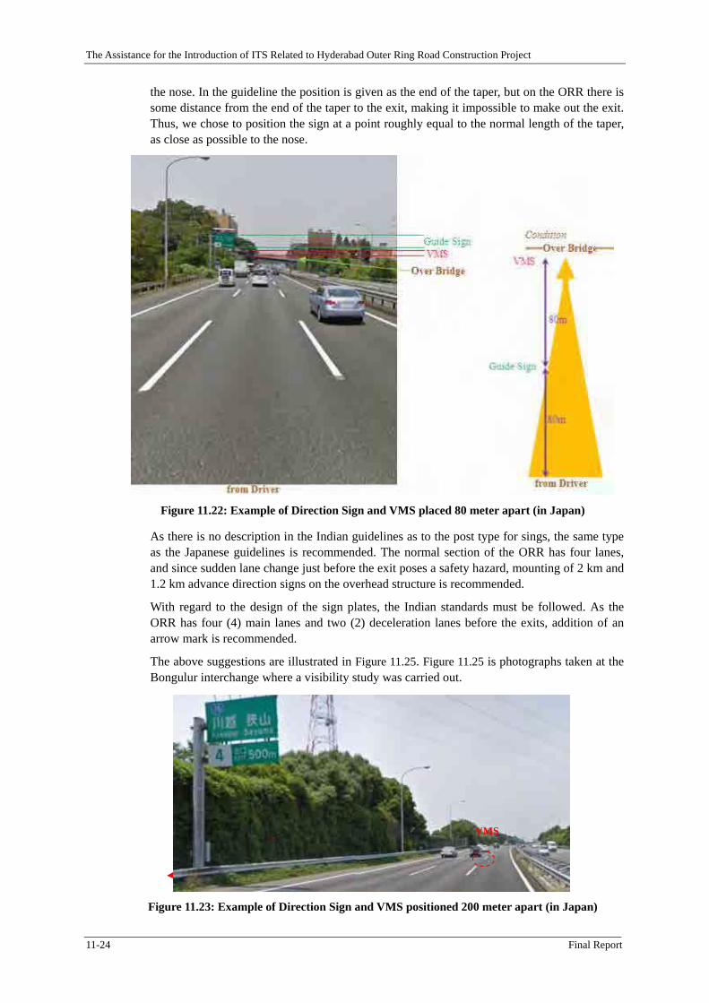
Figure 11.22: Example of Direction Sign and VMS placed 80 meter apart (in Japan) ................... 11-24
Figure 11.23: Example of Direction Sign and VMS positioned 200 meter apart (in Japan) ........... 11-24
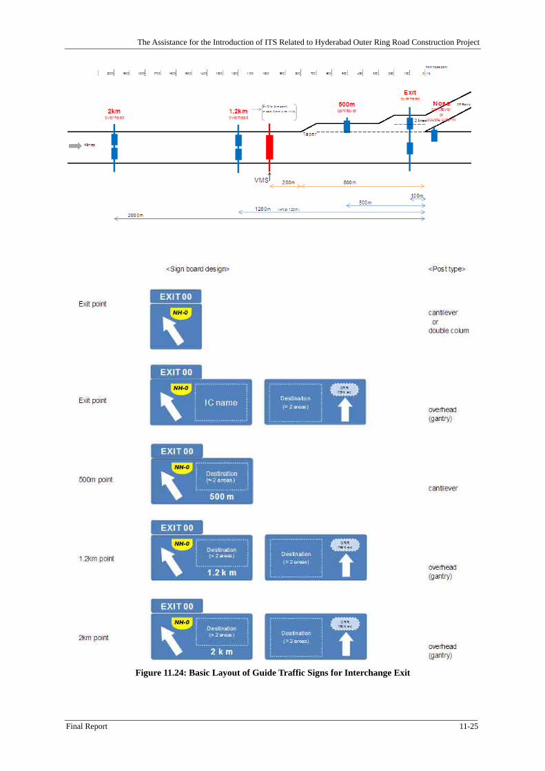
Figure 11.24: Basic Layout of Guide Traffic Signs for Interchange Exit ....................................... 11-25
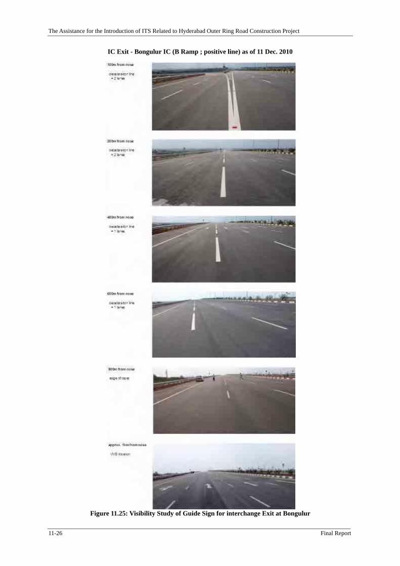
Figure 11.25: Visibility Study of Guide Sign for interchange Exit at Bongulur ............................. 11-26
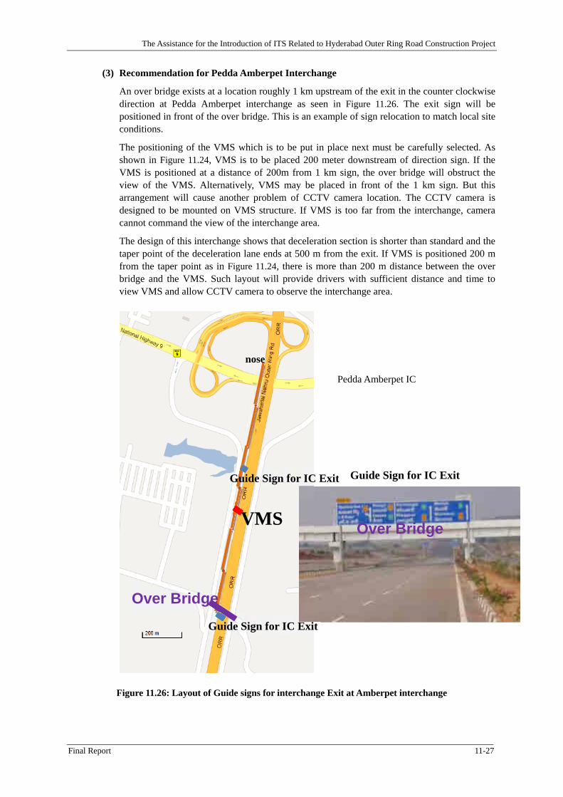
Figure 11.26: Layout of Guide signs for interchange Exit at Amberpet interchange ...................... 11-27
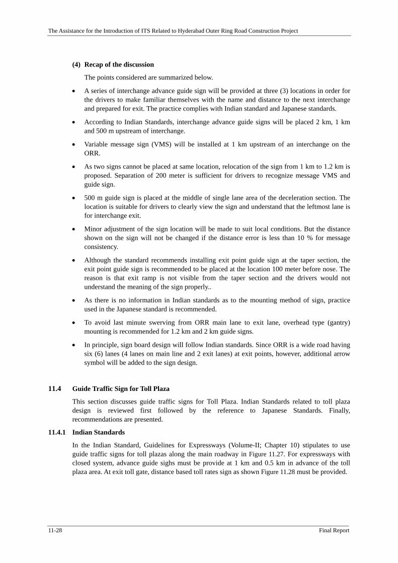
Figure 11.27: Toll Plaza Sign .......................................................................................................... 11-29
Figure 11.28: Toll Rate Sign at Exit ................................................................................................ 11-29
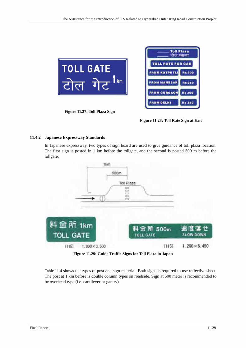
Figure 11.29: Guide Traffic Signs for Toll Plaza in Japan .............................................................. 11-29
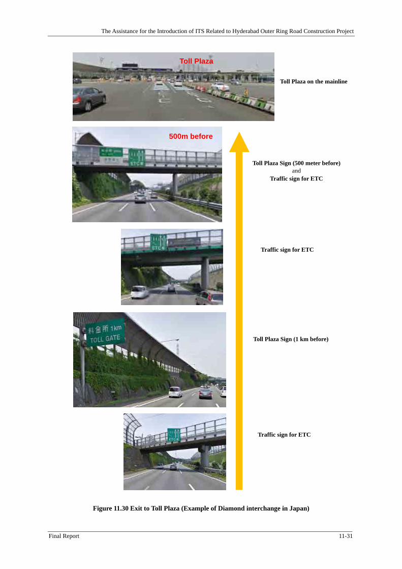
Figure 11.30 Exit to Toll Plaza (Example of Diamond interchange in Japan) ................................ 11-31
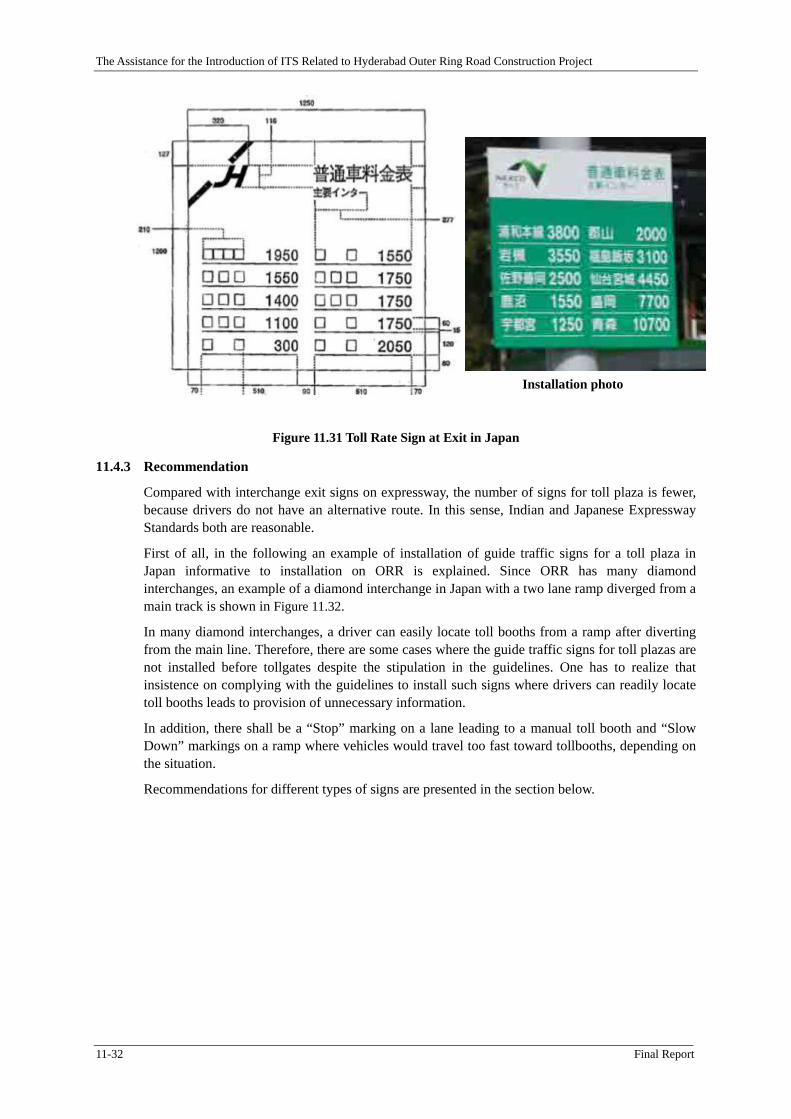
Figure 11.31 Toll Rate Sign at Exit in Japan ................................................................................... 11-32
Figure 11.32 Exit to Toll Plaza (Example of diamond interchange in Japan) ................................. 11-33
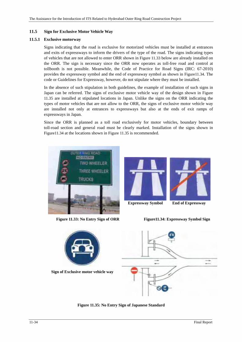
Figure 11.33: No Entry Sign of ORR Figure11.34: Expressway Symbol Sign........ 11-34
Figure 11.35: No Entry Sign of Japanese Standard ........................................................................ 11-34
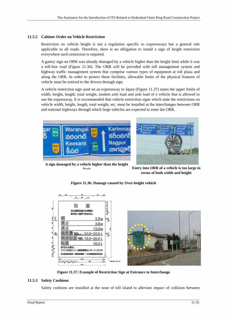
Figure 11.36: Damage caused by Over-height vehicle ................................................................... 11-35
Figure 11.37: Example of Restriction Sign at Entrance to Interchange .......................................... 11-35
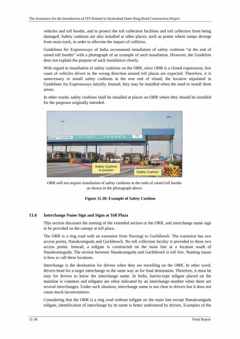
Figure 11.38: Example of Safety Cushion ...................................................................................... 11-36
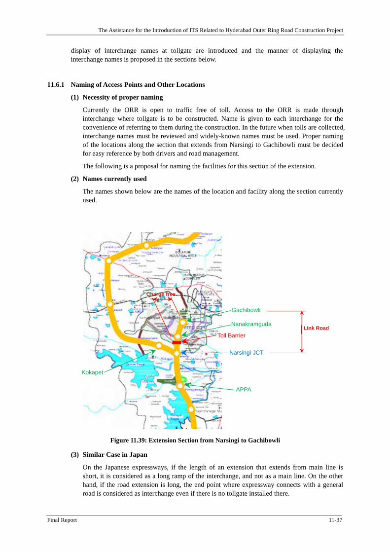
Figure 11.39: Extension Section from Narsingi to Gachibowli ...................................................... 11-37
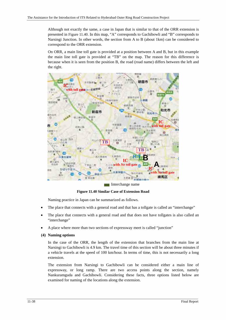
Figure 11.40 Similar Case of Extension Road ................................................................................ 11-38
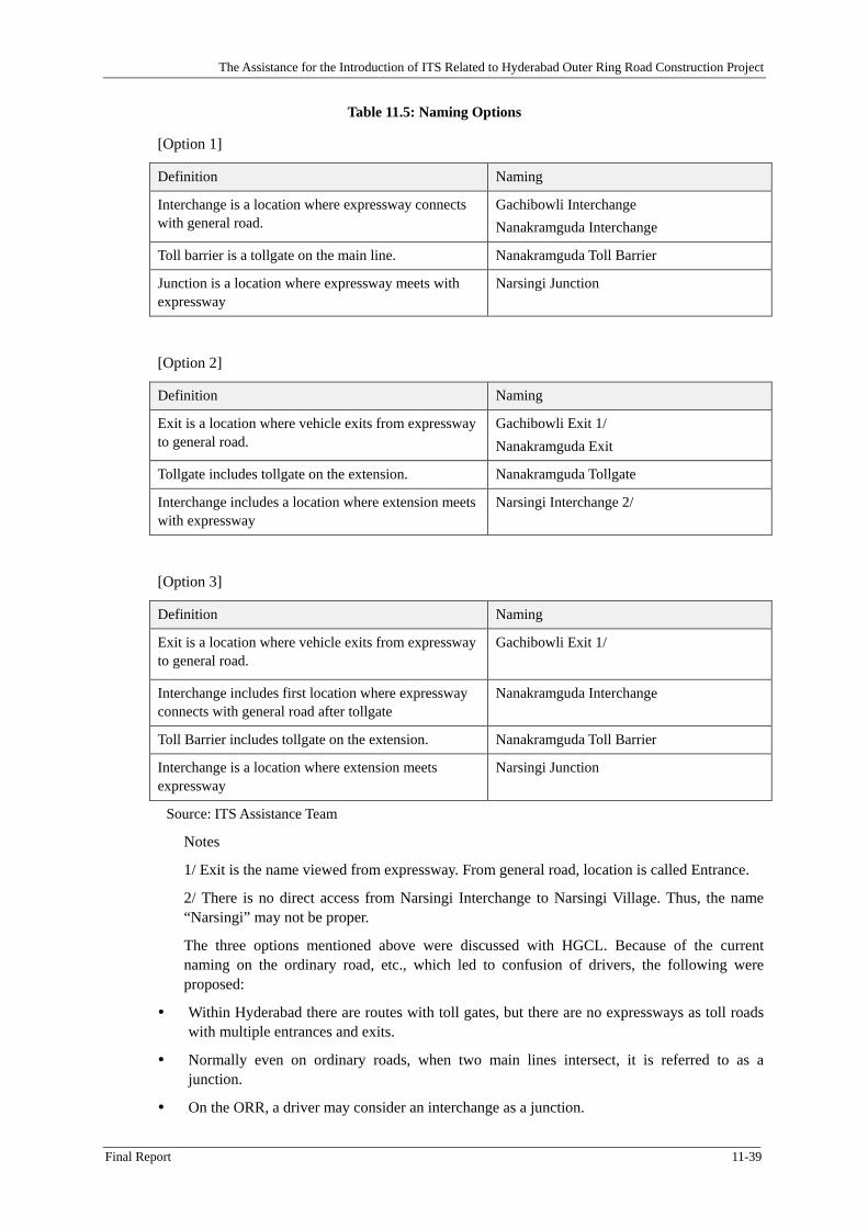
Figure 11.41 Naming Alternative of Facilities on the Extension .................................................... 11-40
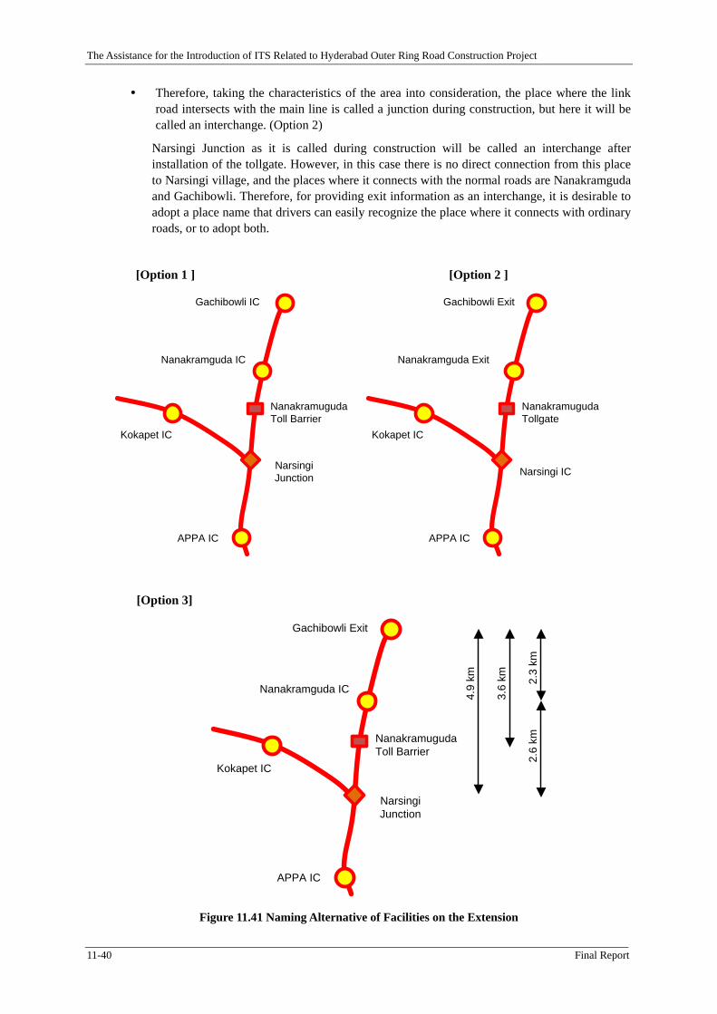
Figure 11.42 Toll Plazas in India .................................................................................................... 11-41
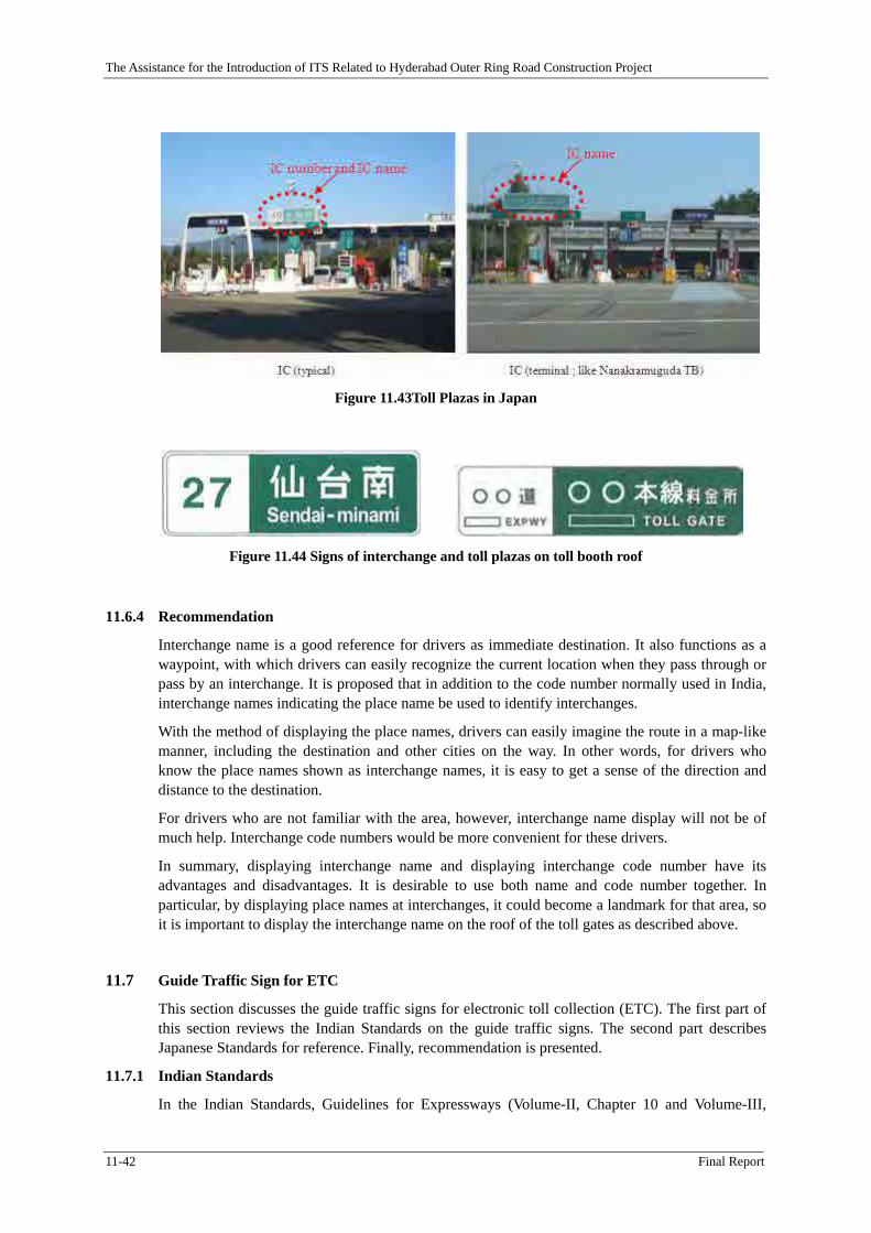
Figure 11.43Toll Plazas in Japan .................................................................................................... 11-42
Figure 11.44 Signs of interchange and toll plazas on toll booth roof ............................................. 11-42
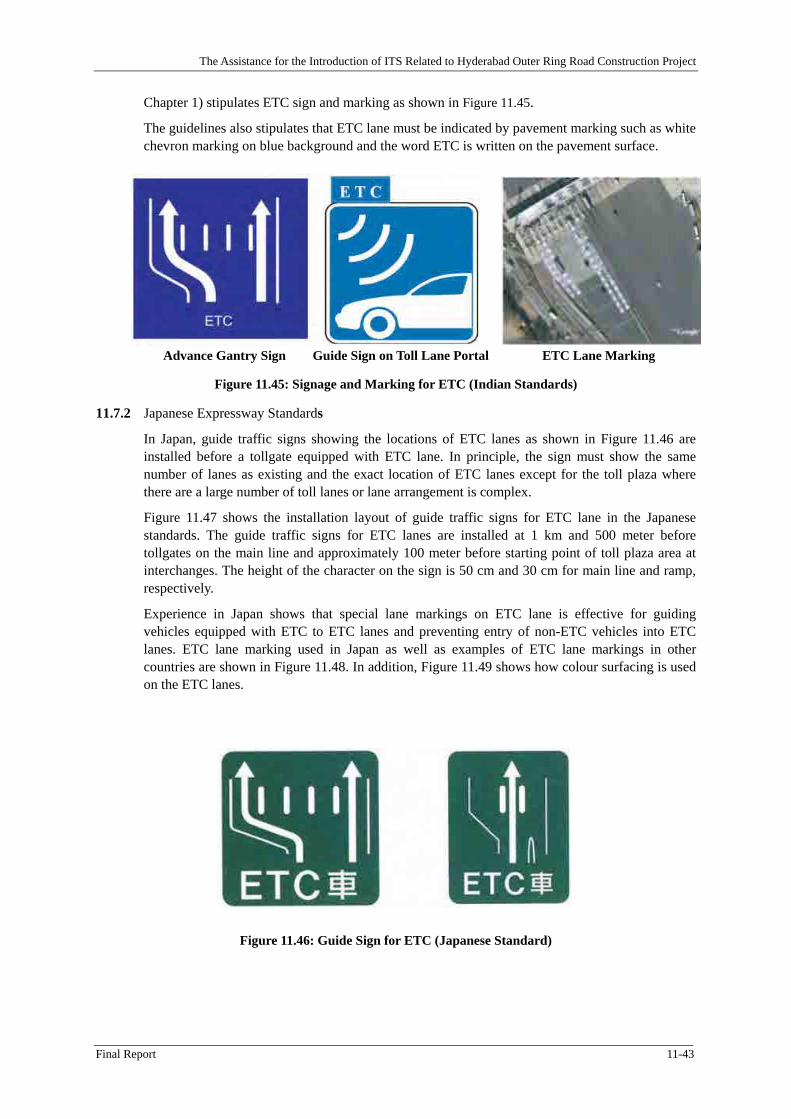
Figure 11.45: Signage and Marking for ETC (Indian Standards) ................................................... 11-43
Figure 11.46: Guide Sign for ETC (Japanese Standard) ................................................................. 11-43
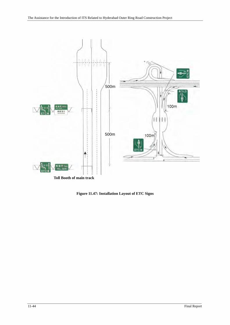
Figure 11.47: Installation Layout of ETC Signs ............................................................................. 11-44
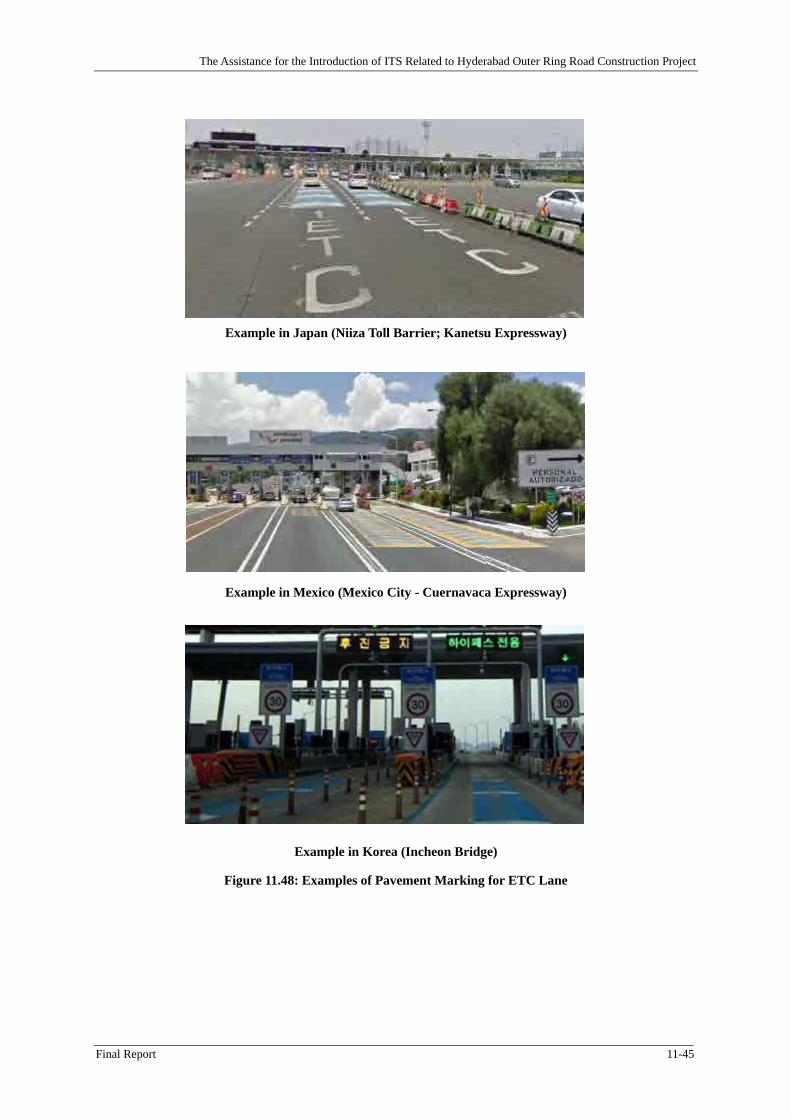
Figure 11.48: Examples of Pavement Marking for ETC Lane ........................................................ 11-45
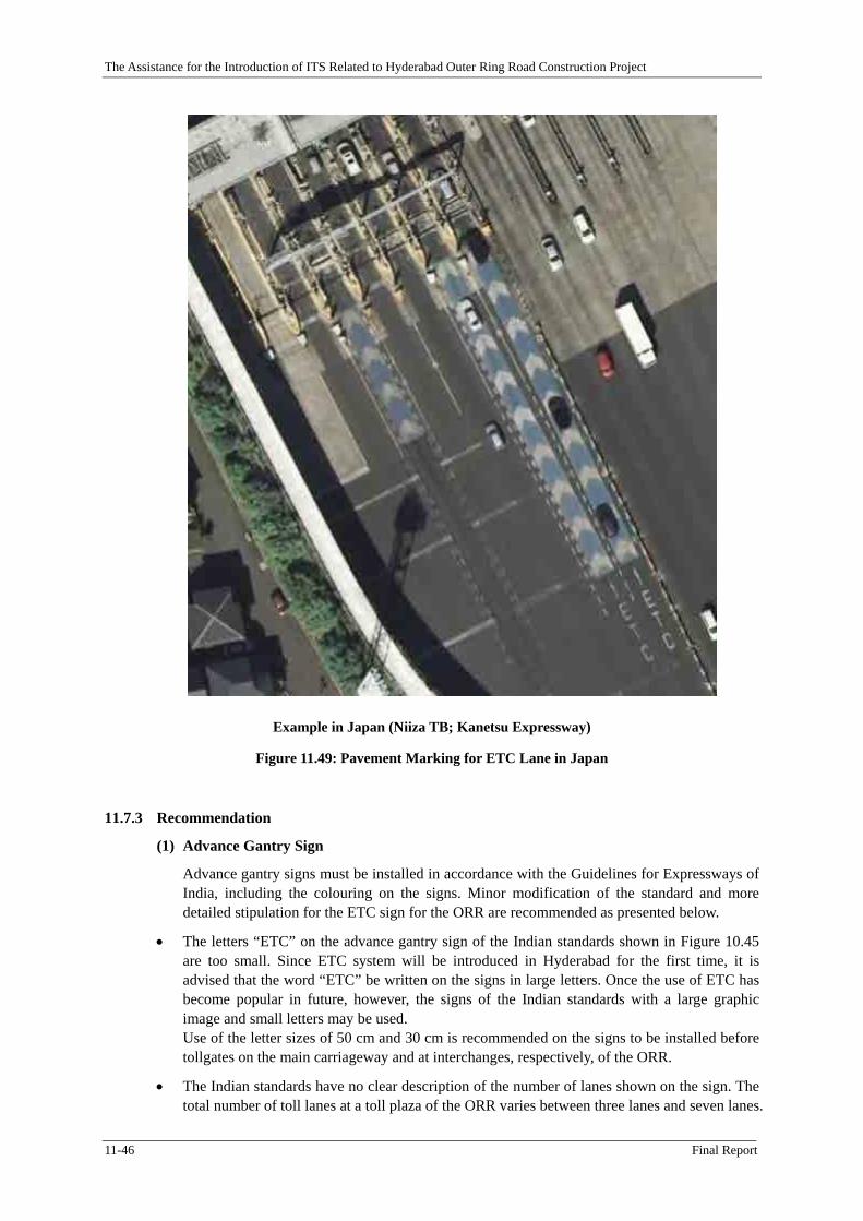
Figure 11.49: Pavement Marking for ETC Lane in Japan .............................................................. 11-46
Figure 11.50: Guide Sign on Toll Lane Portal in India (Delhi – Gurgaon Expressway) ................. 11-47
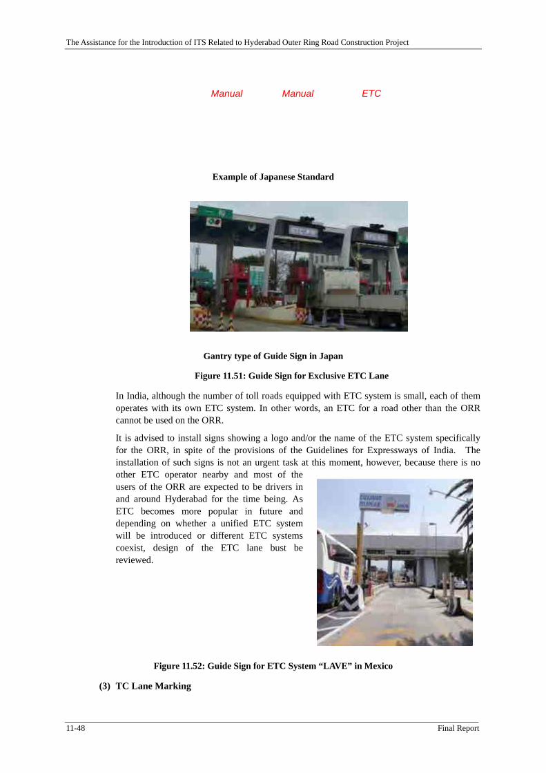
Figure 11.51: Guide Sign for Exclusive ETC Lane ........................................................................ 11-48
Figure 11.52: Guide Sign for ETC System “LAVE” in Mexico ..................................................... 11-48
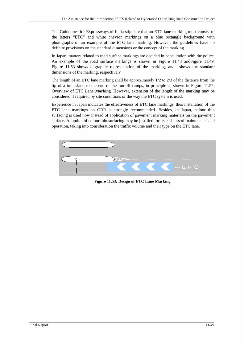
Figure 11.53: Design of ETC Lane Marking .................................................................................. 11-49
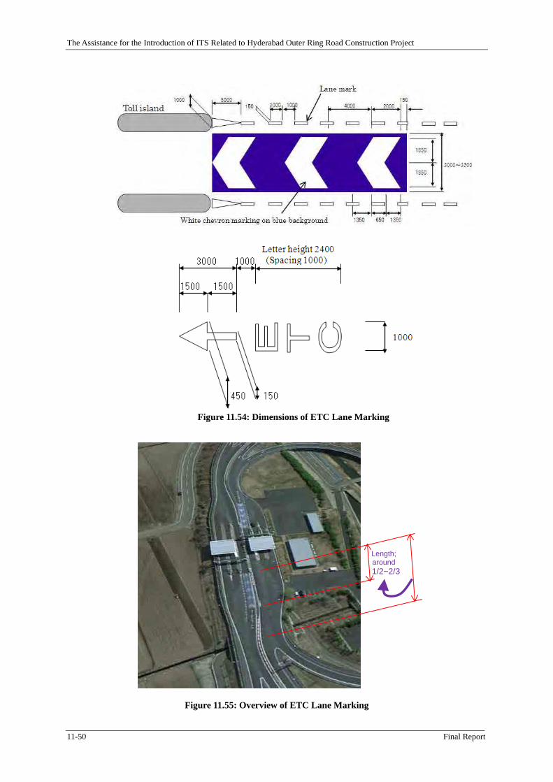
Figure 11.54: Dimensions of ETC Lane Marking ........................................................................... 11-50
Figure 11.55: Overview of ETC Lane Marking .............................................................................. 11-50
Figure 11.56: Design of 100m Marker on Expressway (by Indian Standards) ............................... 11-51
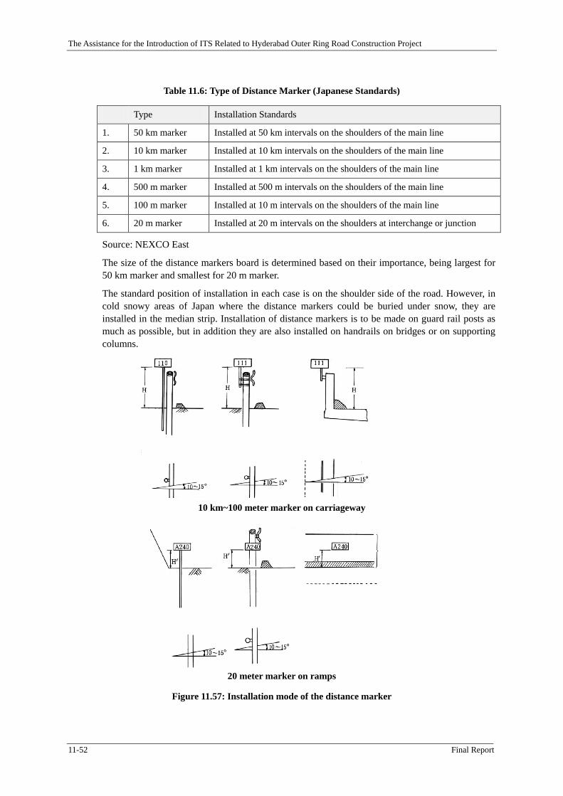
Figure 11.57: Installation mode of the distance marker .................................................................. 11-52
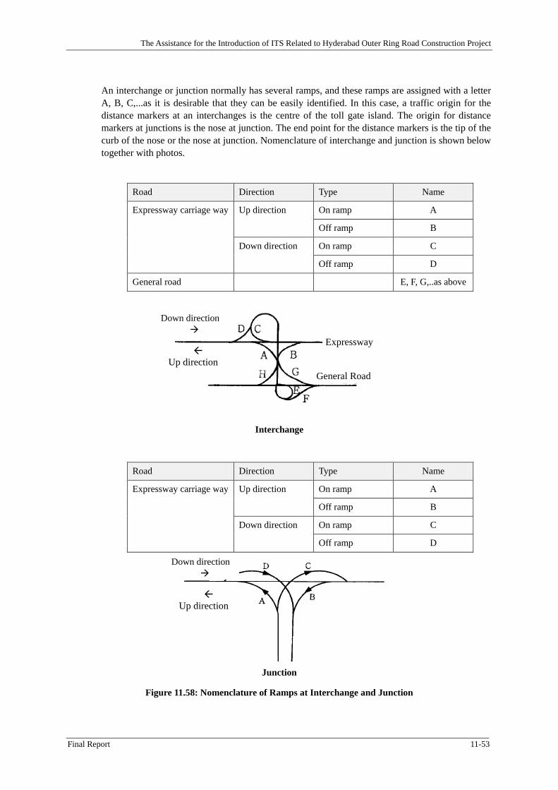
Figure 11.58: Nomenclature of Ramps at Interchange and Junction .............................................. 11-53
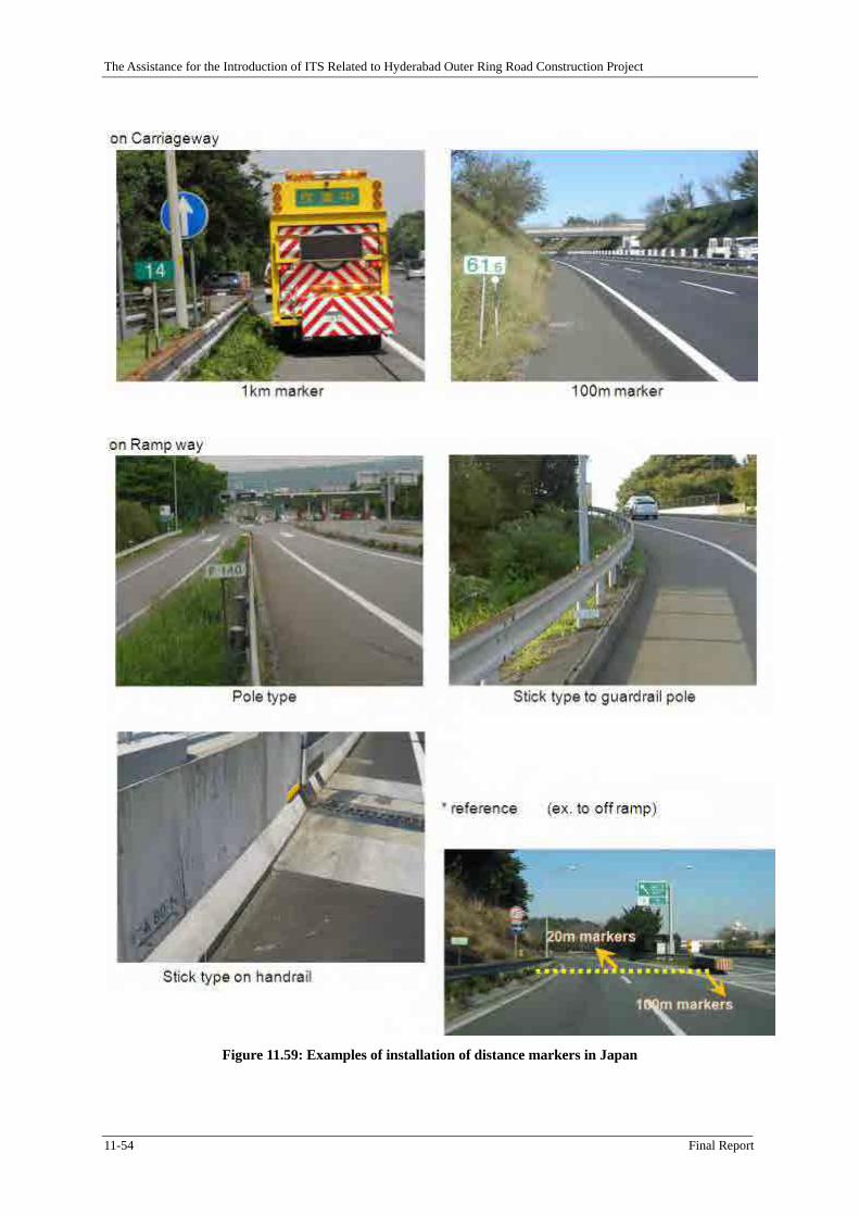
Figure 11.59: Examples of installation of distance markers in Japan ............................................. 11-54
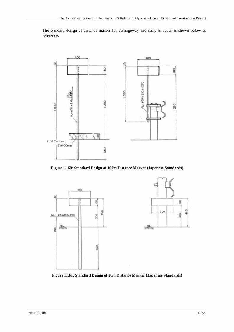
Figure 11.60: Standard Design of 100m Distance Marker (Japanese Standards) ........................... 11-55
Figure 11.61: Standard Design of 20m Distance Marker (Japanese Standards) ............................. 11-55
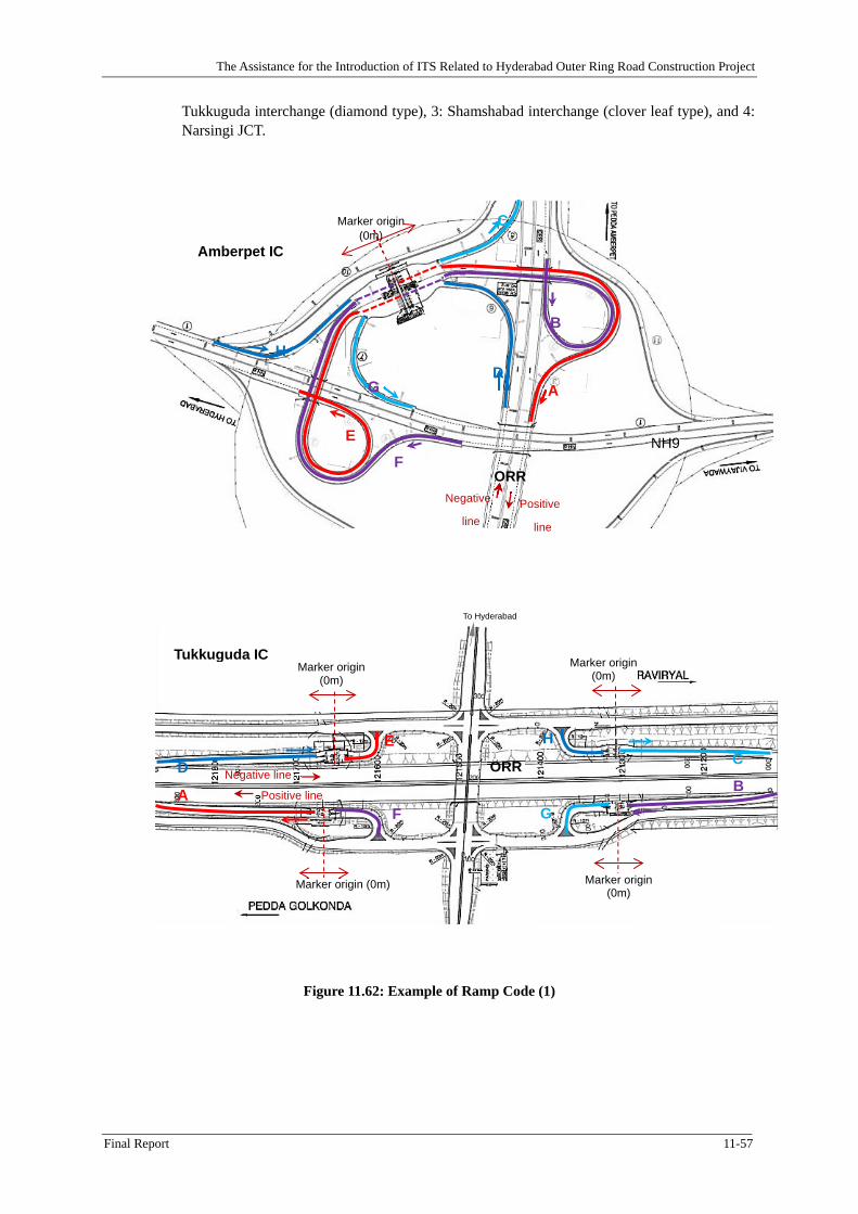
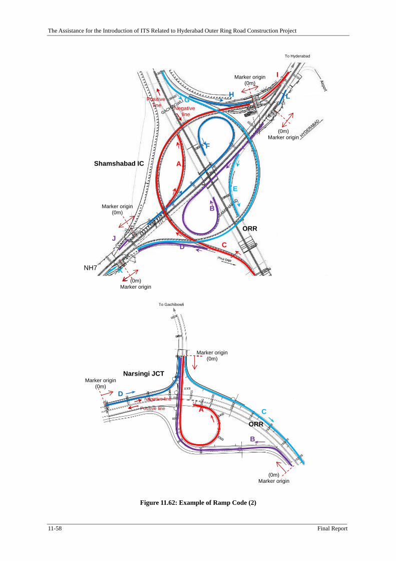
Figure 11.62: Example of Ramp Code (1) ...................................................................................... 11-57
Figure 11.63: Colour of distance marker ........................................................................................ 11-59
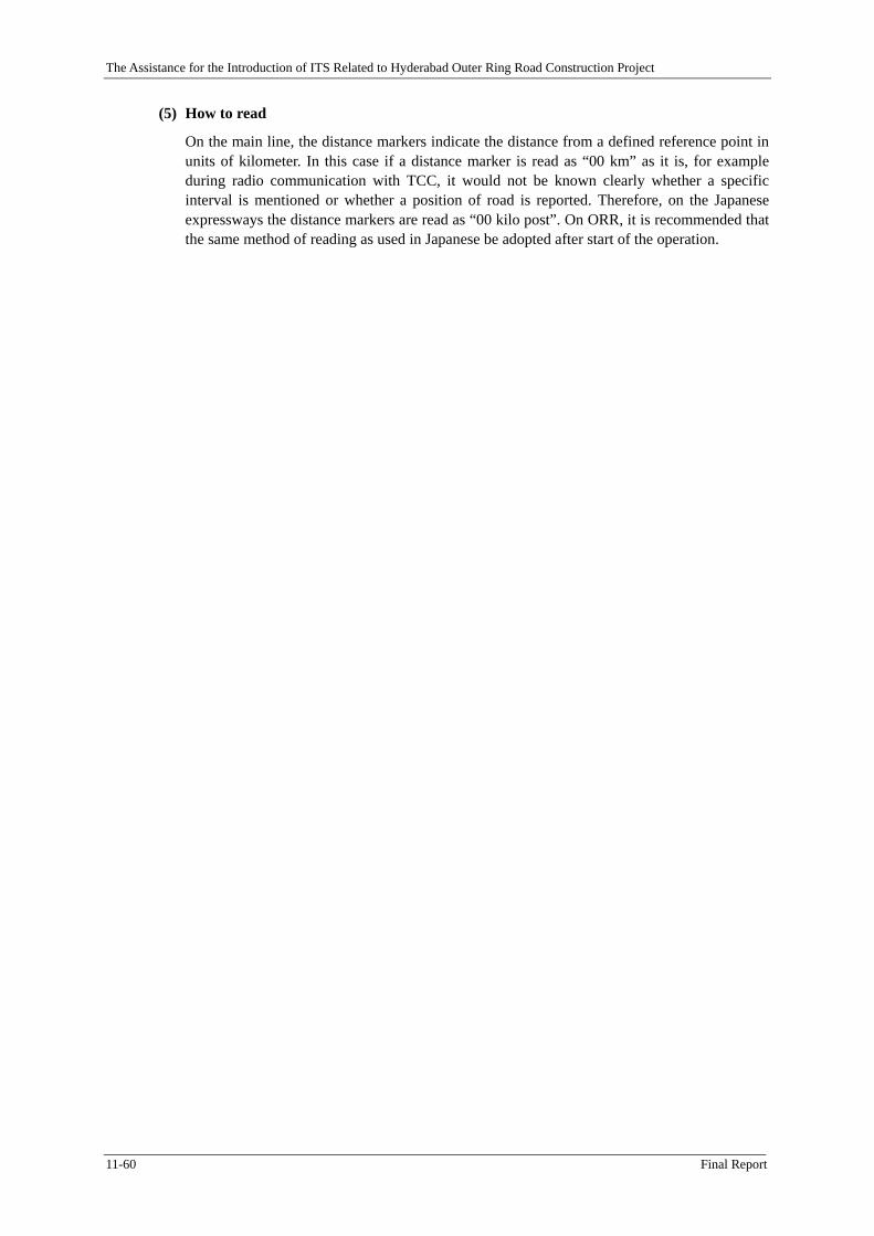
Figure 11.64: Design of 1 km marker ............................................................................................. 11-59
xiii
Abbreviations
AP Andhra Pradesh
APSRTC Andhra Pradesh State Road Transport Corporation
BOT Build-operate-transfer
DSRC Dedicated short range communication
EOI Expression of Interest
ETC Electronic toll collection
GHMC Greater Hyderabad Municipal Corporation
GPRS General packet radio service
GPS Global positioning system
HGCL Hyderabad Growth Corridor Limited
HTMS Highway Traffic Management System
HMDA Hyderabad Metropolitan Development Authority
HUDA Hyderabad Urban Development Authority
IC Interchange
IT Information technology
ITS Intelligent transportation system
JICA Japan International Cooperation Agency
MoRTH Ministry of Road Transport and Highways
MoUD Ministry of Urban Development
NHAI National Highway Authority of India
OBU On-board unit
ORR Outer Ring Road
PCU Passenger car unit
PPP Public-private partnership
PQ Prequalification
RFP Request for proposal
SAPI Special Assistance for Project Implementation
T&G Touch and Go
TCC Traffic Control Centre,
TMS Toll management System
TOR Terms of reference
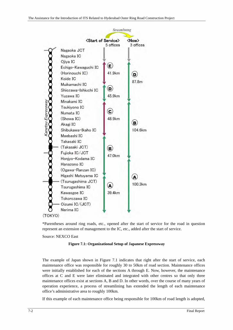
The Assistance for the Introduction of ITS Related to Hyderabad Outer Ring Road Construction Project
Final Report 1-1
Chapter 1 Introduction
1.1 Background
Hyderabad located on the Deccan Plateau in southern India is the capital of Andhra Pradesh State. It is the sixth largest city in India and had a population of 6.4 million in 2001. In recent years, the city has been growing as the country’s hub for information technology with many multinational companies establishing their offices there. Besides this, the city is also known in the film industry as the headquarters of the Ramoji Film City, the largest film studio in the world.
Hyderabad is located at a strategic point in southern India connected not only to suburban towns but also to large cities like Mumbai, Bangalore, and Chennai. The transportation system in the city relies largely on road transportation. The Andhra Pradesh State Road Transport Corporation owns a fleet of 19,000 buses, the largest in the world. The Mahatma Gandhi Bus Station, also known as the Imlibun Bus Station, is the third largest bus terminal in Asia having 72 platforms.
The road network in Hyderabad is radial in configuration with three national highways passing through the city centre: National Highway 7 runs from north to south, National Road 9 runs from northwest to southeast, and National Highway 202 runs toward the northeast. As a result, local traffic mixes with interregional through traffic in the already congested city centre. Aggravating traffic congestion due to the dominance of road-based transportation system and the radial road network is the rapid increase in the number of vehicles in recent years.
Under such circumstances, the state government of Andhra Pradesh decided to construct the Outer Ring Road (ORR) to ease traffic in the city centre and to contribute to the development of the local economy. A loan agreement to finance Phase 2-B of the ORR was signed in November 2008 between the governments of Japan, through the Japan International Cooperation Agency (JICA), and the Republic of India with the Hyderabad Growth Corridor Limited (HGCL) as executing agency. The ORR Phase 2-B includes a component on the introduction of intelligent transportation systems (ITSs).
In order to support the implementation of the ITS components, JICA conducted a Special Assistance for Project Implementation (SAPI) from September 2008 to May 2009 and formulated an implementation plan that included a proposal for an institutional setup to manage the ITS. The implementation plan recommended HGCL to introduce Toll Management System (TMS) and Highway Traffic Management System (HTMS) to the entire stretch of the ORR.
Based on the SAPI recommendations, HGCL decided to construct these systems on the ORR and requested JICA a technical assistance for the project as they don’t have knowledge and experience of these advanced systems. Technical assistance project called “Assistance for the Introduction of ITS Related to the Hyderabad Outer Ring Road Construction Project in the Republic of India” started in February 2010. The technical assistance project assisted HGCL in establishing TMS and HTMS on the ORR, in formulating suitable organization to manage these systems, and in operating and maintaining these systems. The technical assistance project was completed in September 2013.
This Final Report presents the details of the assistance provided by the project.
1.2 Objectives of the Project
To enhance the benefits of developing the Hyderabad Outer Ring Road, the objectives of this project are to assist HGCL in the following area:
Introduce ITS services on the Hyderabad Outer Ring Road; Establish efficient operation and management system; and, Introduce ITS to relevant organizations.
The Assistance for the Introduction of ITS Related to Hyderabad Outer Ring Road Construction Project
1-2 Final Report
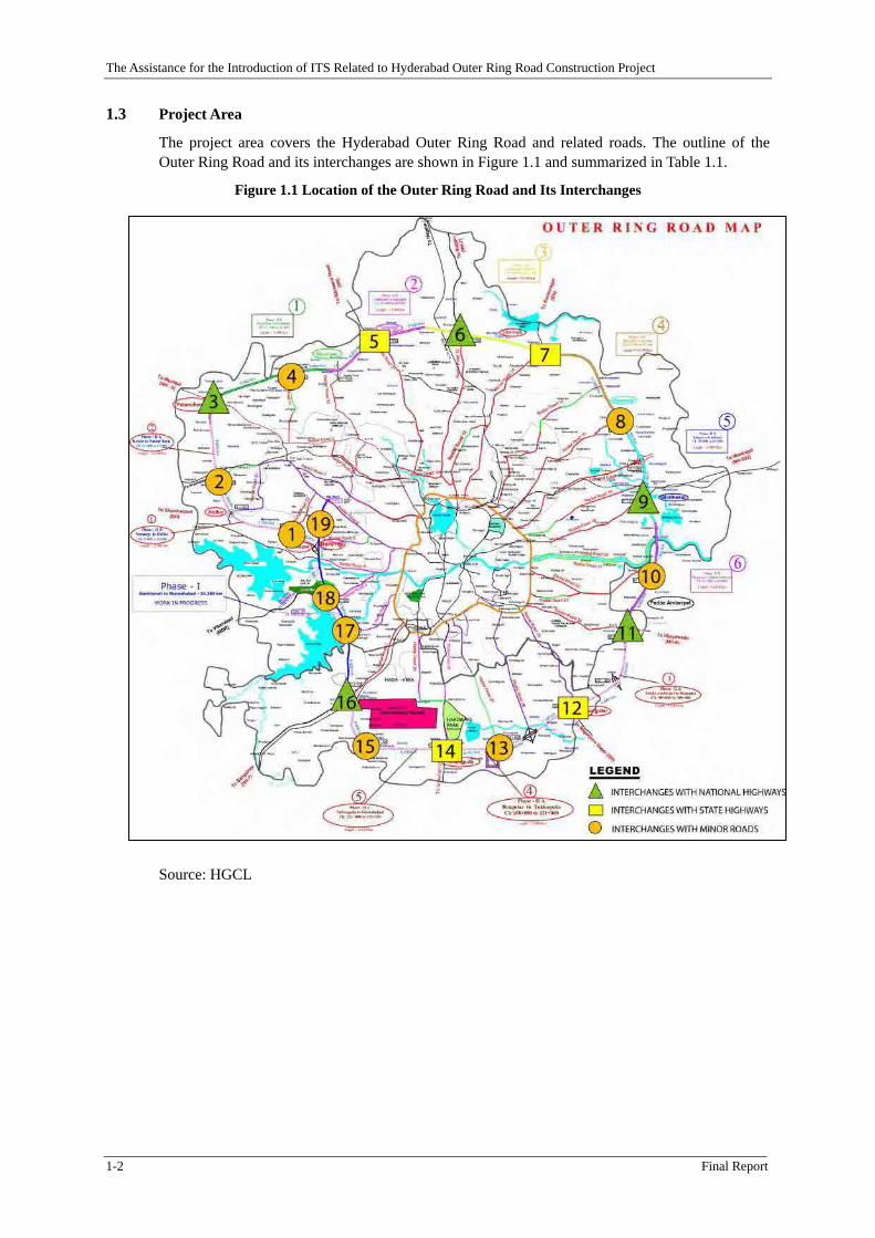
1.3 Project Area
The project area covers the Hyderabad Outer Ring Road and related roads. The outline of the Outer Ring Road and its interchanges are shown in Figure 1.1 and summarized in Table 1.1.
Figure 1.1 Location of the Outer Ring Road and Its Interchanges
Source: HGCL
The Assistance for the Introduction of ITS Related to Hyderabad Outer Ring Road Construction Project
Final Report 1-3
Table 1.1: Interchanges along the Outer Ring Road
Interchange Kilo-post Connecting Road
0 Narsingi 0.000 Junction
1 Kokapet 2.020 MR
2 Idulnagalapalli 13.900 MR
3 Patancheru 22.492 NH-9
4 Sultanpur 31.000 MR
5 Saragudem (Narsapur Rd JCT) 42.700 SH
6 MedchalNarsingi 52.180 NH-7
7 Shamirpet 61.230 SH
8 Keesara 72.970 MR
9 Ghatkesar 81.855 NH-202
10 Taramatipet 89.750 MR
11 Amberpet 96.650 NH-9
12 Bongulur 108.970 SH
13 Raviryal 116.030 MR
14 Tukkuguda 121.500 SH
15 Pedda Goloconda 129.740 MR
16 Shamshabad 133.094 NH-7
17 Rajandranagar 144.285 MR
Rajandranagar (separated IC) 144.630 MR
18 APPA 147.650 MR
19 Nanakramguda 154.370 MR
Source: HGCL
NH: National Highway SH: State Highway MR: Minor road
1.4 Scope of Works
The ITS Introduction Assistance Project consists of the tasks as shown in Table 1.2. Originally there were four (4) main task groups. Later during the course of services, another task was added in response to the request of HGCL. Each task group consists of the tasks as shown in the table. It is noted that due to the delay in the contractor selection process managed by HGCL for toll management system (TMS) and highway traffic management system (HTMS), some of the activities were not conducted and deleted from the list.
The Assistance for the Introduction of ITS Related to Hyderabad Outer Ring Road Construction Project
1-4 Final Report
Table 1.2: Task Composition of ITS Introduction Assistance Project
Activities
Task 1: To conduct surveys on toll collection and ITS introduction, resolution of issues related to maintenance contract and preparation of detailed project schedule
1-1 Conduct of surveys related to toll collection and preparation of details of operation including toll rate setting (including traffic count survey at 20 – 25 locations)
1-2 Confirmation of ITS component to be introduced
1-3 Survey on ITS introduction made by central government and other organizations in India
1-4 Proposal of effective ways of promoting T&G and ETC
1-5 Assistance in preparing detailed schedule of ITS introduction
1-6 A seminar in Japan for Indian officials and staffs regarding the toll collection and ETC.
Task 2: Assistance for the procurement of ITS components.
2-1 Assistance in the preparation of tender documents (including evaluation of ITS (TMS and HTMS) contractors for northern and southern sections of ORR. Preparation of PQ document and holding of PQ were conducted by the JICA expert being dispatched)
2-2 Assistance in preparation of tender documents for ITS consultant (including evaluation of ITS consultant for the construction supervision of northern section of the ORR)
2-3 Assistance in preparation of tender documents for operation & maintenance of ITS.
2-4 Capacity building and lecture related to technical evaluation of ITS contractor
Task 3: Preparation for establishing toll collection management organization and toll collection operation.
3-1 Additional survey for establishing toll road management organization including southern and northern section (including demarcation with BOT concessionaire, confirmation of maintenance contract, and confirmation of traffic management).
3-2 Technical assistance for establishment of toll collection system (including Touch & Go and ETC)
3-3 Preparation of toll collection operations manual
Task 4: Conduct of ETC trial and proposal for full scale operation
4-1 Promotion of understanding on the introduction of ETC by relevant organizations
4-2 Proposal for full-scale introduction and operation of ETC
Task 5: Assistance in establishing HTMS operation organization
5-1 Preparation of HTMS Operation Manual (draft)
5-2 Proposal for liaison and coordination among agencies related to HTMS operation
5-3 Proposal for information exchange with City ITS System
1.5 Project Implementation Arrangements and Milestones
1.5.1 ITS Assistance Team
ITS Assistance Team consisting of 16 experts of various field rendered technical assistance to the HGCL. The team consisted of the following members:
The Assistance for the Introduction of ITS Related to Hyderabad Outer Ring Road Construction Project
Final Report 1-5
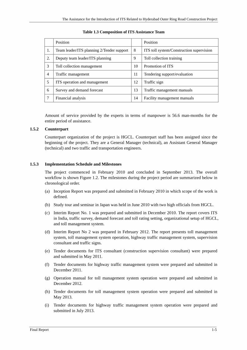
Table 1.3 Composition of ITS Assistance Team
Position Position
1. Team leader/ITS planning 2/Tender support 8 ITS toll system/Construction supervision
2. Deputy team leader/ITS planning 9 Toll collection training
Amount of service provided by the experts in terms of manpower is 56.6 man-months for the entire period of assistance.
1.5.2 Counterpart
Counterpart organization of the project is HGCL. Counterpart staff has been assigned since the beginning of the project. They are a General Manager (technical), an Assistant General Manager (technical) and two traffic and transportation engineers.
1.5.3 Implementation Schedule and Milestones
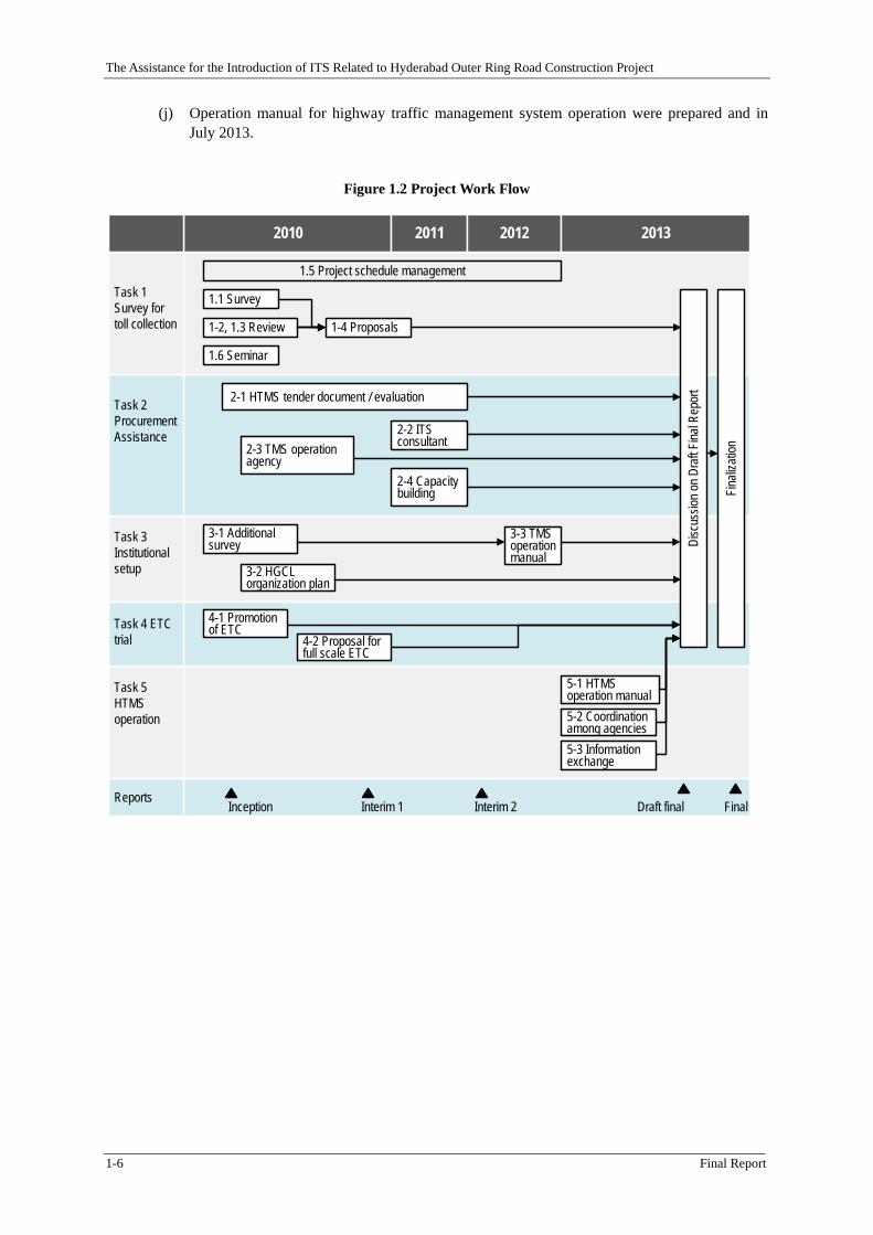
The project commenced in February 2010 and concluded in September 2013. The overall workflow is shown Figure 1.2. The milestones during the project period are summarized below in chronological order.
(a) Inception Report was prepared and submitted in February 2010 in which scope of the work is defined.
(b) Study tour and seminar in Japan was held in June 2010 with two high officials from HGCL.
(c) Interim Report No. 1 was prepared and submitted in December 2010. The report covers ITS in India, traffic survey, demand forecast and toll rating setting, organizational setup of HGCL, and toll management system.
(d) Interim Report No 2 was prepared in February 2012. The report presents toll management system, toll management system operation, highway traffic management system, supervision consultant and traffic signs.
(e) Tender documents for ITS consultant (construction supervision consultant) were prepared and submitted in May 2011.
(f) Tender documents for highway traffic management system were prepared and submitted in December 2011.
(g) Operation manual for toll management system operation were prepared and submitted in December 2012.
(h) Tender documents for toll management system operation were prepared and submitted in May 2013.
(i) Tender documents for highway traffic management system operation were prepared and submitted in July 2013.
The Assistance for the Introduction of ITS Related to Hyderabad Outer Ring Road Construction Project
1-6 Final Report
(j) Operation manual for highway traffic management system operation were prepared and in July 2013.
Figure 1.2 Project Work Flow
1-2, 1.3 Review
1.1 Survey
1.6 Seminar
1-4 Proposals
Task 1 Survey for toll collection
Task 2 Procurement Assistance
Task 3 Institutional setup
Task 4 ETC trial
Task 5 HTMS operation
ReportsInception Interim 1 Interim 2 Draft final Final
5-2 Coordination among agencies
Disc
ussio
n on D
raft F
inal R
epor
t
Finali
zatio
n
3-1 Additional survey
2-4 Capacity building
2-2 ITS consultant
2-1 HTMS tender document / evaluation
3-2 HGCL organization plan
3-3 TMS operation manual
5-1 HTMS operation manual
5-3 Information exchange
1.5 Project schedule management
2-3 TMS operation agency
2010 2011 2012 2013
4-2 Proposal for full scale ETC
4-1 Promotion of ETC
The Assistance for the Introduction of ITS Related to Hyderabad Outer Ring Road Construction Project
Final Report 2-1
Chapter 2 ITS in India
2.1 Overview of ITS in India
2.1.1 Introduction
This section describes present situations about ITS (Intelligent Transportation System), especially about ETC (Electronic Toll Collection) systems in India and promotional strategies of ETC for Hyderabad Outer Ring Road. The objective of this section is to provide related information for ETC operations. It is notable that two large scale commercial electronic tolling systems have been operational in India. One is at Delhi Gurgaon Expressway and the other is at Delhi Noida Toll Bridge (DND Flyway). These preceding examples should be informative for the operation of Hyderabad Ring Road. In July this year Ministry of Road Transport & Highways accepted the Report from ETC Committee which designated technological standards for the tolling system in national roads. This section also describes these governmental activities in Delhi.
2.1.2 Background
There have been consensus among Indian policy makers, administrators, and road operators that introduction of standardized ETC system in national highways is necessary for the reduction of toll fraud and improvement of services. The missing toll fee opportunities are estimated to be Rs. 15 billion every year. Drivers from Mumbai to Delhi have to go through 20 toll gates which became the cause of traffic congestions and annoyances. Road operators have been introducing different ETC systems according to their own decisions as the following sections indicate.
2.1.3 ITS Components to be introduced
“ITS” refers to a wide range of technologies for transportation system based on information technology. Some of them are already implemented and commonly used like electronic toll collection system, while new technologies such as automated driving system is being developed nd it would take some time until the technology is applied to the real world. In between, there are technologies that are being introduced like automatic collision avoiding system using radar.
There are three pillars that support the concept of ITS. They are 1) Safety and security, 2) Environment and efficiency, and 3) Comfort and convenience. ITS is a tool to attain these goals. The ITS technologies mentioned below have the objectives to achieving one or more of these pillars.
Nine target applications of the ITS were selected in case of ITS in Japan. They are 1) navigation system, 2) electronic toll collection, 3) support for safe driving, 4) traffic management, 5) road management, 6) public transport operation management, 7) commercial vehicles operation management, 8) pedestrian support, and 9) emergency vehicle management. Specific technologies to be developed and applied are selected under each category. As the list above shows, ITS covers a wide variety of applications. Each of them is at different development stage. Thus not all of these technologies are applicable to the ORR.
ITS components to be introduced to the ORR have been selected considering that the ORR is an access controlled expressway for automobiles only. The components selected are electronic toll collection (ETC) and highway traffic management system (HTMS). ETC is one of the toll collection method for toll road and constitute a part of toll management system. HTMS is a system composed of various equipment to manage road and traffic to attain the goals of safe, comfortable and efficient road transportation system. Configuration, function and other details of these systems are presented in the section of respective systems.
2.2 Preceding Operational Examples of ETC in India
2.2.1 Delhi Gurgaon Expressway
The Assistance for the Introduction of ITS Related to Hyderabad Outer Ring Road Construction Project
2-2 Final Report
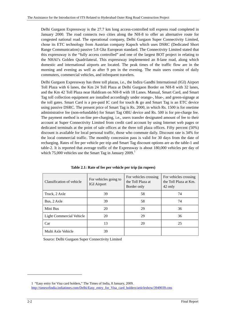
Delhi Gurgaon Expressway is the 27.7 km long access-controlled toll express road completed in January 2000. The road connects two cities along the NH-8 to offer an alternative route for congested national road. The operational company, Delhi Gurgaon Super Connectivity Limited, chose its ETC technology from Austrian company Kapsch which uses DSRC (Dedicated Short Range Communication) passive 5.8 Ghz European standard. The Connectivity Limited stated that this expressway is the “fully access controlled” and one of the largest BOT project in relating to the NHAI’s Golden Quadrilateral. This expressway implemented an 8-lane road, along which domestic and international airports are located. The peak times of the traffic flow are in the morning and evening as well as after 9 pm in the evening. The main users consist of daily commuters, commercial vehicles, and infrequent travelers.
Delhi Gurgaon Expressway has three toll plazas, i.e., the Indira Gandhi International (IGI) Airport Toll Plaza with 6 lanes, the Km 24 Toll Plaza at Delhi Gurgaon Border on NH-8 with 32 lanes, and the Km 42 Toll Plaza near Haldiram on NH-8 with 18 Lanes. Manual, Smart Card, and Smart Tag toll collection equipment are installed accordingly under orange-, blue-, and green-signage at the toll gates. Smart Card is a pre-paid IC card for touch & go and Smart Tag is an ETC device using passive DSRC. The present price of Smart Tag is Rs. 2000, in which Rs. 1500 is for onetime administrative fee (non-refundable) for Smart Tag OBU device and Rs. 500 is for pre-charge fee. The payment method is on-line pre-charging, i.e., users transfer designated amount of fee to their account at Super Connectivity Limited from credit card account by using Internet web pages or dedicated terminals at the point of sale offices at the three toll plaza offices. Fifty percent (50%) discount is available for local personal traffic, those who commute daily. Discount rate is 34% for the local commercial traffic. The monthly concession pass is valid for 30 days from the date of recharging. Rates of fee per vehicle per trip and Smart Tag discount options are as the table-1 and table-2. It is reported that average traffic of the Expressway is about 180,000 vehicles per day of which 75,000 vehicles use the Smart Tag in January 2009.1
Table 2.1: Rate of fee per vehicle per trip (in rupees)
Classification of vehicle For vehicles going to IGI Airport
For vehicles crossing the Toll Plaza at Border only
For vehicles crossing the Toll Plaza at Km. 42 only
Truck, 2 Axle 39 58 74
Bus, 2 Axle 39 58 74
Mini Bus 20 29 36
Light Commercial Vehicle 20 29 36
Car 13 20 25
Multi Axle Vehicle 39
Source: Delhi Gurgaon Super Connectivity Limited
1 “Easy entry for Visa card holders,” The Times of India, 8 January, 2009. http://timesofindia.indiatimes.com/Delhi/Easy_entry_for_Visa_card_holders/articleshow/3949039.cms
The Assistance for the Introduction of ITS Related to Hyderabad Outer Ring Road Construction Project
Final Report 2-3
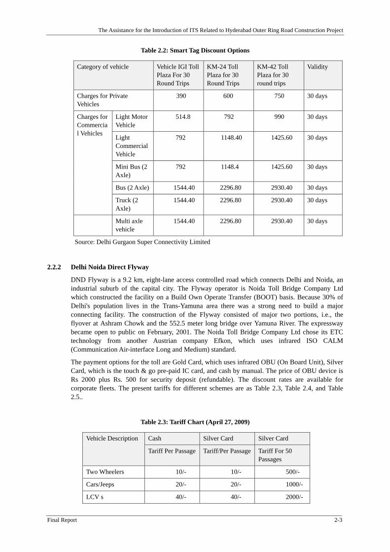
Table 2.2: Smart Tag Discount Options
Category of vehicle
Vehicle IGI Toll Plaza For 30 Round Trips
KM-24 Toll Plaza for 30 Round Trips
KM-42 Toll Plaza for 30 round trips
Validity
Charges for Private Vehicles
390 600 750 30 days
Charges for Commercial Vehicles
Light Motor Vehicle
514.8 792 990 30 days
Light Commercial Vehicle
792 1148.40 1425.60 30 days
Mini Bus (2 Axle)
792 1148.4 1425.60 30 days
Bus (2 Axle) 1544.40 2296.80 2930.40 30 days
Truck (2 Axle)
1544.40 2296.80 2930.40 30 days
Multi axle vehicle
1544.40 2296.80 2930.40 30 days
Source: Delhi Gurgaon Super Connectivity Limited
2.2.2 Delhi Noida Direct Flyway
DND Flyway is a 9.2 km, eight-lane access controlled road which connects Delhi and Noida, an industrial suburb of the capital city. The Flyway operator is Noida Toll Bridge Company Ltd which constructed the facility on a Build Own Operate Transfer (BOOT) basis. Because 30% of Delhi's population lives in the Trans-Yamuna area there was a strong need to build a major connecting facility. The construction of the Flyway consisted of major two portions, i.e., the flyover at Ashram Chowk and the 552.5 meter long bridge over Yamuna River. The expressway became open to public on February, 2001. The Noida Toll Bridge Company Ltd chose its ETC technology from another Austrian company Efkon, which uses infrared ISO CALM (Communication Air-interface Long and Medium) standard.
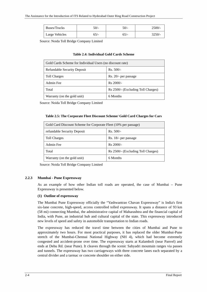
The payment options for the toll are Gold Card, which uses infrared OBU (On Board Unit), Silver Card, which is the touch & go pre-paid IC card, and cash by manual. The price of OBU device is Rs 2000 plus Rs. 500 for security deposit (refundable). The discount rates are available for corporate fleets. The present tariffs for different schemes are as Table 2.3, Table 2.4, and Table 2.5..
Table 2.3: Tariff Chart (April 27, 2009)
Vehicle Description Cash Silver Card Silver Card
Tariff Per Passage Tariff/Per Passage Tariff For 50 Passages
Two Wheelers 10/- 10/- 500/-
Cars/Jeeps 20/- 20/- 1000/-
LCV s 40/- 40/- 2000/-
The Assistance for the Introduction of ITS Related to Hyderabad Outer Ring Road Construction Project
2-4 Final Report
Buses/Trucks 50/- 50/- 2500/-
Large Vehicles 65/- 65/- 3250/-
Source: Noida Toll Bridge Company Limited
Table 2.4: Individual Gold Cards Scheme
Gold Cards Scheme for Individual Users (no discount rate)
Refundable Security Deposit Rs. 500/-
Toll Charges Rs. 20/- per passage
Admin Fee Rs 2000/-
Total Rs 2500/- (Excluding Toll Charges)
Warranty (on the gold unit) 6 Months
Source: Noida Toll Bridge Company Limited
Table 2.5: The Corporate Fleet Discount Scheme/ Gold Card Charges for Cars
Gold Card Discount Scheme for Corporate Fleet (10% per passage)
refundable Security Deposit Rs. 500/-
Toll Charges Rs. 18/- per passage
Admin Fee Rs 2000/-
Total Rs 2500/- (Excluding Toll Charges)
Warranty (on the gold unit) 6 Months
Source: Noida Toll Bridge Company Limited
2.2.3 Mumbai - Pune Expressway
As an example of how other Indian toll roads are operated, the case of Mumbai – Pune Expressway is presented below.
(1) Outline of expressway
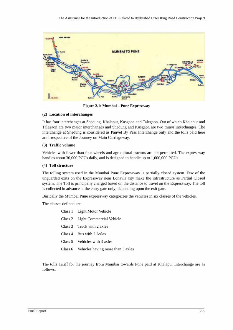
The Mumbai Pune Expressway officially the “Yashwantrao Chavan Expressway” is India's first six-lane concrete, high-speed, access controlled tolled expressway. It spans a distance of 93 km (58 mi) connecting Mumbai, the administrative capital of Maharashtra and the financial capital of India, with Pune, an industrial hub and cultural capital of the state. This expressway introduced new levels of speed and safety in automobile transportation to Indian roads.
The expressway has reduced the travel time between the cities of Mumbai and Pune to approximately two hours. For most practical purposes, it has replaced the older Mumbai-Pune stretch of the Mumbai-Chennai National Highway (NH 4), which had become extremely congested and accident-prone over time. The expressway starts at Kalamboli (near Panvel) and ends at Dehu Rd. (near Pune). It cleaves through the scenic Sahyadri mountain ranges via passes and tunnels. The expressway has two carriageways with three concrete lanes each separated by a central divider and a tarmac or concrete shoulder on either side.
The Assistance for the Introduction of ITS Related to Hyderabad Outer Ring Road Construction Project
Final Report 2-5
Figure 2.1: Mumbai – Pune Expressway
(2) Location of interchanges
It has four interchanges at Shedung, Khalapur, Kusgaon and Talegaon. Out of which Khalapur and Talegaon are two major interchanges and Shedung and Kusgaon are two minor interchanges. The interchange at Shedung is considered as Panvel By Pass Interchange only and the tolls paid here are irrespective of the Journey on Main Carriageway.
(3) Traffic volume
Vehicles with fewer than four wheels and agricultural tractors are not permitted. The expressway handles about 30,000 PCUs daily, and is designed to handle up to 1,000,000 PCUs.
(4) Toll structure
The tolling system used in the Mumbai Pune Expressway is partially closed system. Few of the unguarded exits on the Expressway near Lonavla city make the infrastructure as Partial Closed system. The Toll is principally charged based on the distance to travel on the Expressway. The toll is collected in advance at the entry gate only; depending upon the exit gate.
Basically the Mumbai Pune expressway categorizes the vehicles in six classes of the vehicles.
The classes defined are
Class 1 Light Motor Vehicle
Class 2 Light Commercial Vehicle
Class 3 Truck with 2 axles
Class 4 Bus with 2 Axles
Class 5 Vehicles with 3 axles
Class 6 Vehicles having more than 3 axles
The tolls Tariff for the journey from Mumbai towards Pune paid at Khalapur Interchange are as follows;
The Assistance for the Introduction of ITS Related to Hyderabad Outer Ring Road Construction Project
2-6 Final Report
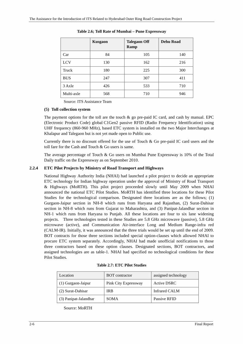
Table 2.6; Toll Rate of Mumbai – Pune Expressway
Kusgaon Talegaon Off
Ramp Dehu Road
Car 84 105 140
LCV 130 162 216
Truck 180 225 300
BUS 247 307 411
3 Axle 426 533 710
Multi-axle 568 710 946
Source: ITS Assistance Team
(5) Toll collection system
The payment options for the toll are the touch & go pre-paid IC card, and cash by manual. EPC (Electronic Product Code) global C1Gen2 passive RFID (Radio Frequency Identification) using UHF frequency (860-960 MHz), based ETC system is installed on the two Major Interchanges at Khalapur and Talegaon but is not yet made open to Public use.
Currently there is no discount offered for the use of Touch & Go pre-paid IC card users and the toll fare for the Cash and Touch & Go users is same.
The average percentage of Touch & Go users on Mumbai Pune Expressway is 10% of the Total Daily traffic on the Expressway as on September 2010.
2.2.4 ETC Pilot Projects by Ministry of Road Transport and Highways
National Highway Authority India (NHAI) had launched a pilot project to decide an appropriate ETC technology for Indian highway operation under the approval of Ministry of Road Transport & Highways (MoRTH). This pilot project proceeded slowly until May 2009 when NHAI announced the national ETC Pilot Studies. MoRTH has identified three locations for these Pilot Studies for the technological comparison. Designated three locations are as the follows; (1) Gurgaon-Jaipur section in NH-8 which runs from Haryana and Rajasthan, (2) Surat-Dahisar section in NH-8 which runs from Gujarat to Maharashtra, and (3) Panipat-Jalandhar section in NH-1 which runs from Haryana to Punjab. All these locations are four to six lane widening projects. Three technologies tested in these Studies are 5.8 GHz microwave (passive), 5.8 GHz microwave (active), and Communication Air-interface Long and Medium Range-infra red (CALM-IR). Initially, it was announced that the three trials would be set up until the end of 2009. BOT contracts for those three sections included special option-clauses which allowed NHAI to procure ETC system separately. Accordingly, NHAI had made unofficial notifications to those three contractors based on these option clauses. Designated sections, BOT contractors, and assigned technologies are as table-1. NHAI had specified no technological conditions for these Pilot Studies.
Table 2.7: ETC Pilot Studies
Location BOT contractor assigned technology
(1) Gurgaon-Jaipur Pink City Expressway Active DSRC
(2) Surat-Dahisar IRB Infrared CALM
(3) Panipat-Jalandhar SOMA Passive RFID
Source: MoRTH
The Assistance for the Introduction of ITS Related to Hyderabad Outer Ring Road Construction Project
Final Report 2-7
As for the Infrared CALM team, it is reported that discrepancy emerges about the manual toll gate system Efkon has procured. Efkon group and anti- Efkon group inside the BOT contractor could not become accommodated about the evaluation to the manual system. Efkon’s proposed On Board Unit (OBU) is a one-piece type.
As for the passive RFID team, Kapsch, Q-free, and GEA have submitted proposals to the BOT contractor. It is reported that Kapsch received an unofficial notification but two venders conducted rollbacks which brought the situation uncontrollable. Three companies’ proposals are the same European CEN standard one-piece type.
As for the Active DSRC team, Mitsubishi Heavy Industry (MHI) and Efkon have submitted the proposals. Neither NHAI nor the BOT contractor was able to decide because proposed two technologies and solutions are entirely different. MHI‘s proposal is two-piece type, while Efkon’s is one-piece.
Partly because the lack of technological specifications from the NHAI and partly because ETC selections are imposed upon the BOT contractors who do not have technological backgrounds, the impasse had seemed to continue throughout in 2009.
2.2.5 ETC Committee and its Report
In January 2010 MoRTH Minister Mr. Kamal Nath took initiatives to establish the ETC Committee which is independent from MoRTH and headed by Mr. Nandan Nilekani who had served as the CEO of Infosys from 2002 to 2007. Mr. Nilekani left Infosys in July 2009 to serve as the chairperson of the Unique Identification Authority of India (UIDAI), in the rank of a cabinet minister. UIDAI now works for the introduction of national ID card system.
On 28 June, 2010, ETC Committee submitted the Report to Mr. Nath, who told the reporters on 2 July that the committee's Report has been accepted by the government, adding that this scheme would be implemented in the next 18-20 months.
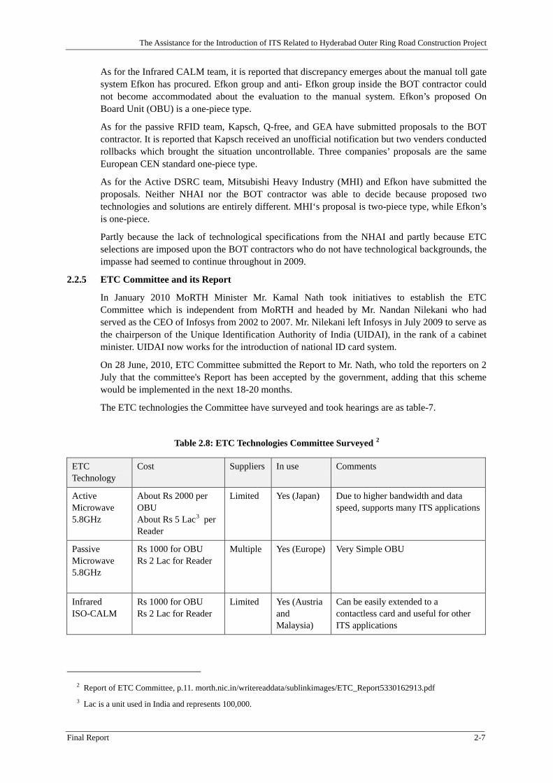
The ETC technologies the Committee have surveyed and took hearings are as table-7.
Table 2.8: ETC Technologies Committee Surveyed 2
ETC Technology
Cost Suppliers In use Comments
Active Microwave 5.8GHz
About Rs 2000 per OBU About Rs 5 Lac3 per Reader
Limited Yes (Japan) Due to higher bandwidth and data speed, supports many ITS applications
Passive Microwave 5.8GHz
Rs 1000 for OBU Rs 2 Lac for Reader
Multiple Yes (Europe) Very Simple OBU
Infrared ISO-CALM
Rs 1000 for OBU Rs 2 Lac for Reader
Limited Yes (Austria and Malaysia)
Can be easily extended to a contactless card and useful for other ITS applications
2 Report of ETC Committee, p.11. morth.nic.in/writereaddata/sublinkimages/ETC_Report5330162913.pdf 3 Lac is a unit used in India and represents 100,000.
The Assistance for the Introduction of ITS Related to Hyderabad Outer Ring Road Construction Project
2-8 Final Report
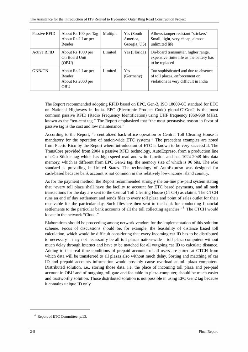
Passive RFID About Rs 100 per Tag About Rs 2 Lac per Reader
Multiple Yes (South America, Georgia, US)
Allows tamper resistant "stickers" Small, light, very cheap, almost unlimited life
Active RFID About Rs 1000 per On Board Unit (OBU)
Limited Yes (Florida) On-board transmitter, higher range, expensive finite life as the battery has to be replaced
GNN/CN About Rs 2 Lac per Reader About Rs 2000 per OBU
Limited Yes (Germany)
Too sophisticated and due to absence of toll plazas, enforcement on violations is very difficult in India
The Report recommended adopting RFID based on EPC, Gen-2, ISO 18000-6C standard for ETC on National Highways in India. EPC (Electronic Product Code) global C1Gen2 is the most common passive RFID (Radio Frequency Identification) using UHF frequency (860-960 MHz), known as the “ten-cent tag.” The Report emphasized that “the most persuasive reason in favor of passive tag is the cost and low maintenance.”
According to the Report, “a centralized back office operation or Central Toll Clearing House is mandatory for the operation of nation-wide ETC systems.” The precedent examples are noted from Puerto Rico by the Report where introduction of ETC is known to be very successful. The TransCore provided from 2004 a passive RFID technology, AutoExpreso, from a production line of eGo Sticker tag which has high-speed read and write function and has 1024-2048 bits data memory, which is different from EPC Gen-2 tag, the memory size of which is 96 bits. The eGo standard is prevailing in United States. The technology of AutoExpreso was designed for cash-based because bank account is not common in this relatively low-income island country.
As for the payment method, the Report recommended strongly the on-line pre-paid system stating that “every toll plaza shall have the facility to account for ETC based payments, and all such transactions for the day are sent to the Central Toll Clearing House (CTCH) as claims. The CTCH runs an end of day settlement and sends files to every toll plaza and point of sales outlet for their receivable for the particular day. Such files are then sent to the bank for conducting financial settlements to the particular bank accounts of all the toll collecting agencies.”4 The CTCH would locate in the network “Cloud.”
Elaborations should be proceeding among network vendors for the implementation of this solution scheme. Focus of discussions should be, for example, the feasibility of distance based toll calculation, which would be difficult considering that every incoming car ID has to be distributed to necessary – may not necessarily be all toll plazas nation-wide – toll plaza computers without much delay through Internet and have to be matched for all outgoing car ID to calculate distance. Adding to that real time conditions of prepaid accounts of all users are stored at CTCH from which data will be transferred to all plazas also without much delay. Sorting and matching of car ID and prepaid accounts information would possibly cause overload at toll plaza computers. Distributed solution, i.e., storing those data, i.e. the place of incoming toll plaza and pre-paid account in OBU and of outgoing toll gate and fee table in plaza-computer, should be much easier and trustworthy solution. Those distributed solution is not possible in using EPC Gen2 tag because it contains unique ID only.
4 Report of ETC Committee, p.13.
The Assistance for the Introduction of ITS Related to Hyderabad Outer Ring Road Construction Project
Final Report 2-9
2.3 Promotion of ETC in India
2.3.1 Overall Discussions
There is a wide consensus that BOT - based road concession necessitates toll collections as soonas possible. On the other hand, road users in Hyderabad have to become accustomed to a new way of using roads, i.e., paying tolls manually or electronically. Therefore, public relations and marketing promotions should be indispensable at least at the introductory phases.
The following guidelines are appropriate for public relations; a) rules and disciplines should beaccountable and well-prepared. Feedback loops should be built-in; b) the PR should be based onmedia-mix. Media-mix means an integrated strategy for public relations by commercial specialists of mass media. All media, i.e., newspapers, magazines, radio programs, TV channels, and Internet web pages should be appropriately combined. Feedbacks, i.e., users’ opinions and claims should be properly treated by appropriate sections established for this purpose.
2.3.2 Promotion of ETC (1): ETC Trial Operations for Users
(1) Pre-charge of Smart card
Smart card pre-charged, for example, INR 1000 for OBU and smart card pre-charged INR 200 fortouch & go will be distributed for monitors on the condition that they will participate in the ETCtrial operation in ORR. This kind of promotion will attract not only early users but also attentions of general audience.
(2) Distribution of free OBU (On Board Unit)
Distribution of free OBU for the recurrent users of the Outer Ring Road, for example, hotel transportations, bus companies, and cargo Lorries should promote their usage significantly. An appropriate numbers are, for example, 1000 OBUs and 3000 smart cards for the ETC Trial.
(3) Promotional scheme for the marketing of ETC apparatus
Marketing scheme should include promotional scheme for the ETC apparatus, for example, OBU equipment could have lease and refundable options.
2.3.3 Promotion of ETC (2): the best practice is the fare discount for ETC users
ETC users should be beneficial for the usage of the Touch & Go smart card and the OBU based ETC. It is notable that road operator and fee collectors are beneficial from pre-paid ETC systembecause it allows a fund deposit which yields interest. Significance of the introduction of special discount rate for ETC users is well proven in Japan. Example below stated that NEXCO East,Centre, and West offer maximum 50 % discount or up to 1000 yen reduction at the rural areaduring the weekend and holiday for ETC users specifically.
The Assistance for the Introduction of ITS Related to Hyderabad Outer Ring Road Construction Project
2-10 Final Report
2.3.4 Discount service and Data Configuration of the Smart card
Certain Smart card data configurations have to ensure promotional discount services. Table-1 is the data configuration of the Smart card. The following data sets relate to the discount services.
(1) Category
Manual and T&G/OBU users are distinguishable by using this data set.
(2) date/time
This data set is used for the traffic record and time zone discount with the combination of car classification as follows;
Night time discount rate is applied to multi-axle lorry. Heavy cargo trucks are allowed to enter inside the city from 10 PM to 5 AM. This discount rate is to enhance them using ORR in mid night;
Holiday time discount rate is applied to family-use car. This service is to promote the long drive on holidays when commercial use of the road decrease.
(3) Mileage record
User’s accumulated kilometers are stored in Smart card. This data set is used for a frequent flier program and makes possible the mileage discount.
Table 2.9: Typical Data Structure of Smart Card
data set contents Specifications & functions required numbers
unique ID card numbers Numbers are allocated when cards are distributed or purchased. IDs and sales record are registered in DB.
12 Bytes is the Unique Code of Card
category (Static)
(1) manual (2) T&G/OBU (3) exempt
“category” is necessary because same smart cards are used for three purposes.
2 Bytes
usage (Static)
(a) fare payer (b) commuter
Commuters purchase same OD by frequency based like 100 times.
2
car classification (Static)
(a) passenger car (b) lorry (c) …
Car classification is necessary to calculate fare. charged fare = a unit price ×distance=A
“User background” is necessary for corporate discounting. Discount fare = A × b%
3 Bytes
OD data (Dynamic)
(a) Origination (b) Destination
(i) Manual Operation (a) Toll gate ID had been written by using R/W in the booth. When a car enters the gate, an Smart card is handed out from the operator to the driver who carries it to the destination toll gate. (b)Toll gate operator receives the smart card
50
The Assistance for the Introduction of ITS Related to Hyderabad Outer Ring Road Construction Project
Final Report 2-11
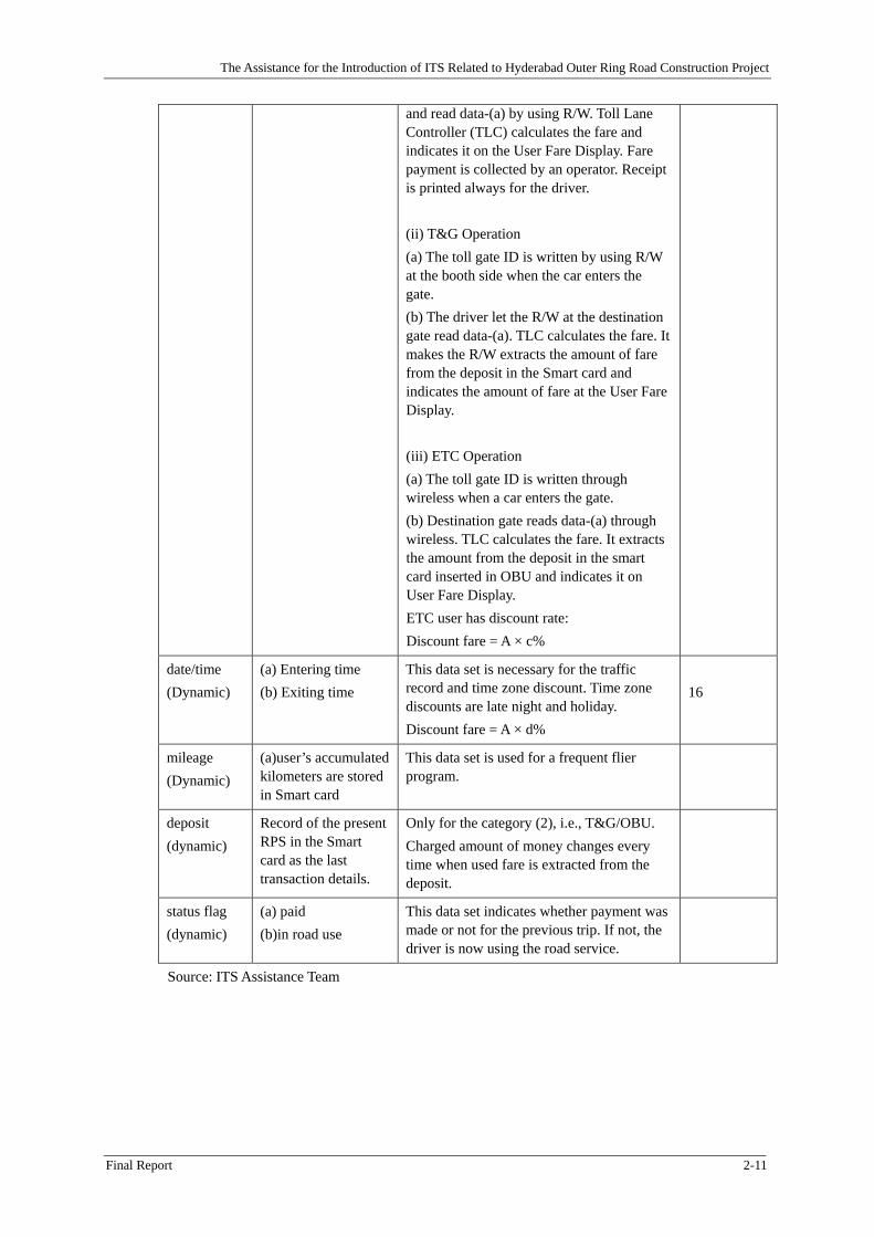
and read data-(a) by using R/W. Toll Lane Controller (TLC) calculates the fare and indicates it on the User Fare Display. Fare payment is collected by an operator. Receipt is printed always for the driver. (ii) T&G Operation (a) The toll gate ID is written by using R/W at the booth side when the car enters the gate. (b) The driver let the R/W at the destination gate read data-(a). TLC calculates the fare. It makes the R/W extracts the amount of fare from the deposit in the Smart card and indicates the amount of fare at the User Fare Display. (iii) ETC Operation (a) The toll gate ID is written through wireless when a car enters the gate. (b) Destination gate reads data-(a) through wireless. TLC calculates the fare. It extracts the amount from the deposit in the smart card inserted in OBU and indicates it on User Fare Display. ETC user has discount rate: Discount fare = A × c%
date/time (Dynamic)
(a) Entering time (b) Exiting time
This data set is necessary for the traffic record and time zone discount. Time zone discounts are late night and holiday. Discount fare = A × d%
16
mileage (Dynamic)
(a)user’s accumulated kilometers are stored in Smart card
This data set is used for a frequent flier program.
deposit (dynamic)
Record of the present RPS in the Smart card as the last transaction details.
Only for the category (2), i.e., T&G/OBU. Charged amount of money changes every time when used fare is extracted from the deposit.
status flag (dynamic)
(a) paid (b)in road use
This data set indicates whether payment was made or not for the previous trip. If not, the driver is now using the road service.
Source: ITS Assistance Team
The Assistance for the Introduction of ITS Related to Hyderabad Outer Ring Road Construction Project
Final Report 3-1
Chapter 3 Traffic Survey, Demand Forecast and Toll Rate Setting
3.1 Traffic Survey
3.1.1 Objectives of Traffic Survey
The objectives of traffic survey are:
1) To examine the existing traffic survey result on the national highway across Outer Ring Road (hereinafter referred “ORR”).
2) To identify possible conversion traffic to ORR.
3) To identify drivers time value and willingness to pay toll road.
3.1.2 Type of Survey and Survey Method
Following traffic surveys were carried out in this study.
1) Traffic Count Survey
2) Roadside OD Interview Survey
3.1.3 Method of Traffic Count Survey
The traffic count survey was conducted to get the hourly traffic volume by vehicle type and by direction and was carried out using manual traffic counters to record the number of vehicle passing an observation point along a road for 24-hour period.
The categories of surveyed vehicle type are classifies as follows:
Motorcycle Three Wheeler/ Auto Rickshaw Passenger car (sedan, jeep, van/cab) Mini Bus Bus Light Truck (Light Cargo Vehicle: LCV) Small Truck (2 Axles) Medium Truck (3 Axles) Large Truck (Multi Axles / Trailer) Other Motorized Vehicle
3.1.4 Method of Roadside OD Interview Survey
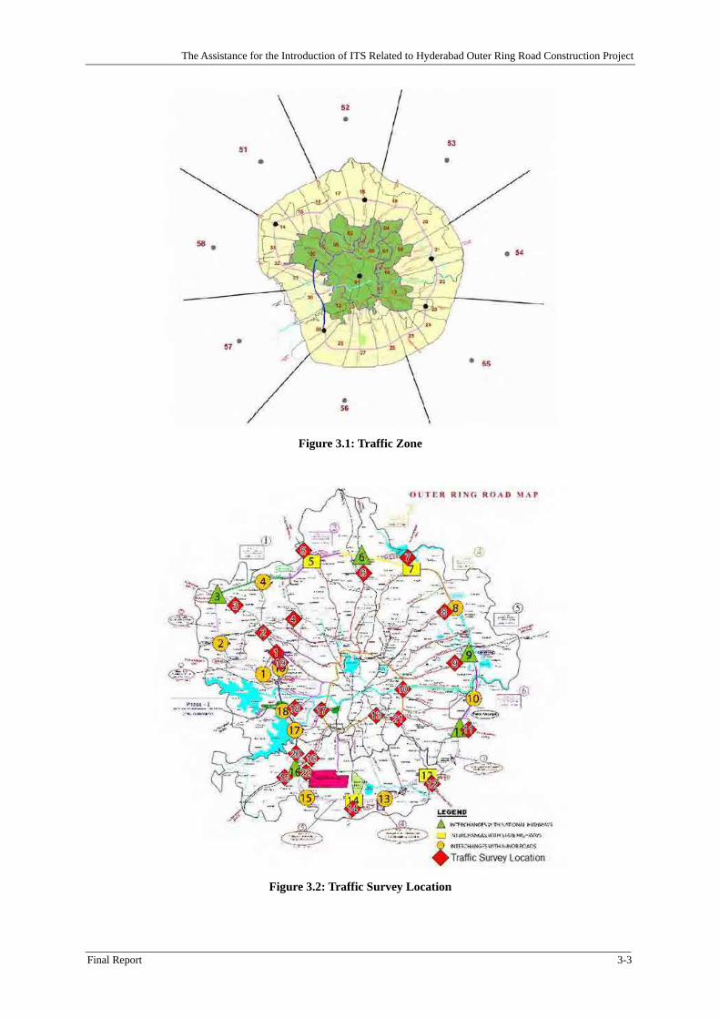
Trip information was collected through interviews with sampled vehicle drivers at roadside. Sample rate depend on the traffic volume on the surveyed road. This survey was to stop vehicles at roadside for the interview in cooperation with traffic police. The vehicle classification was applied same categories with the traffic count survey. And this OD interview follows traffic zoning adopted in “JICA SAPI for Hyderabad ORR Construction Project Phase I, JICA, 2009”*5 as shown in Figure 3.1.
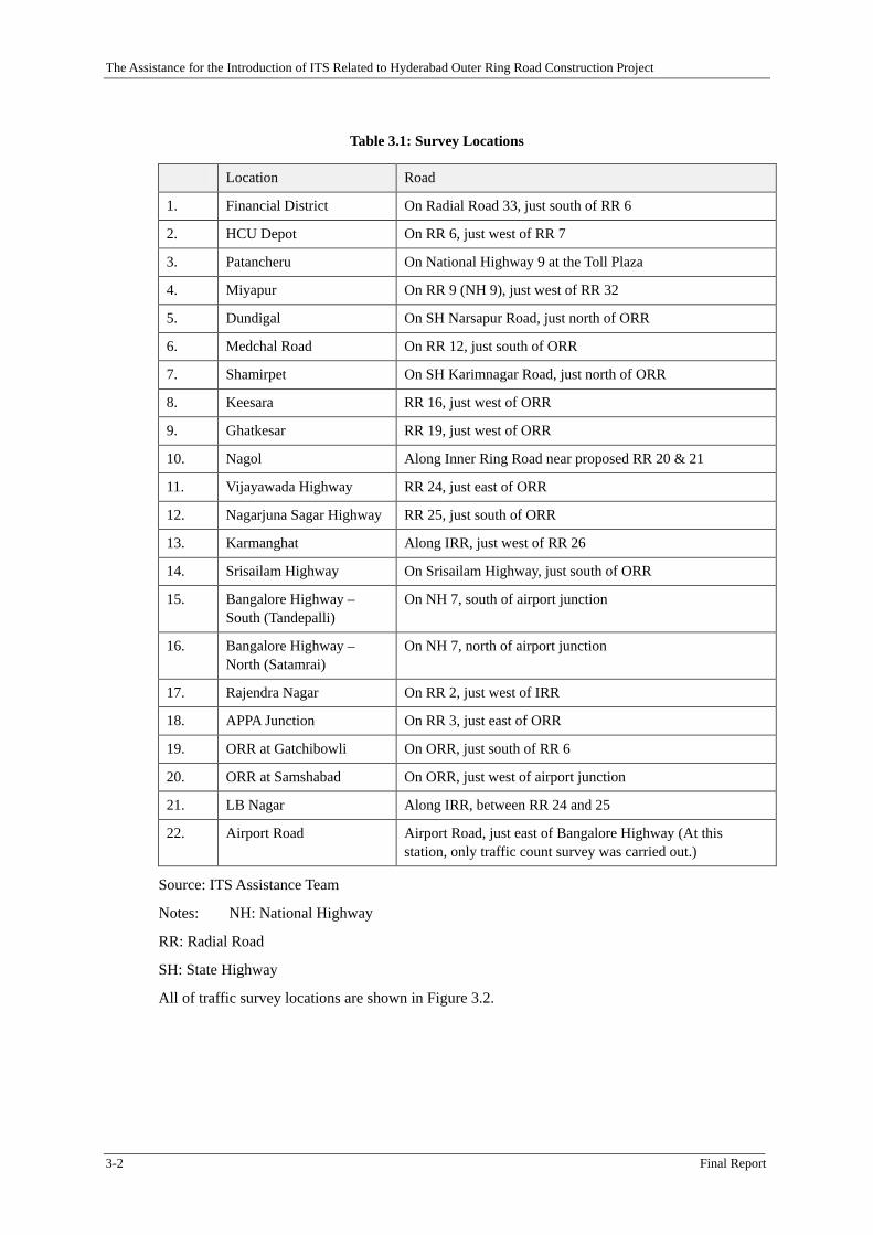
3.1.5 Traffic Survey Locations
Traffic survey locations were following 22 locations;
*5 Hereinafter referred “JICA SAPI”.
The Assistance for the Introduction of ITS Related to Hyderabad Outer Ring Road Construction Project
3-2 Final Report
Table 3.1: Survey Locations
Location Road
1. Financial District On Radial Road 33, just south of RR 6
2. HCU Depot On RR 6, just west of RR 7
3. Patancheru On National Highway 9 at the Toll Plaza
4. Miyapur On RR 9 (NH 9), just west of RR 32
5. Dundigal On SH Narsapur Road, just north of ORR
6. Medchal Road On RR 12, just south of ORR
7. Shamirpet On SH Karimnagar Road, just north of ORR
8. Keesara RR 16, just west of ORR
9. Ghatkesar RR 19, just west of ORR
10. Nagol Along Inner Ring Road near proposed RR 20 & 21
11. Vijayawada Highway RR 24, just east of ORR
12. Nagarjuna Sagar Highway RR 25, just south of ORR
13. Karmanghat Along IRR, just west of RR 26
14. Srisailam Highway On Srisailam Highway, just south of ORR
15. Bangalore Highway – South (Tandepalli)
On NH 7, south of airport junction
16. Bangalore Highway – North (Satamrai)
On NH 7, north of airport junction
17. Rajendra Nagar On RR 2, just west of IRR
18. APPA Junction On RR 3, just east of ORR
19. ORR at Gatchibowli On ORR, just south of RR 6
20. ORR at Samshabad On ORR, just west of airport junction
21. LB Nagar Along IRR, between RR 24 and 25
22. Airport Road Airport Road, just east of Bangalore Highway (At this station, only traffic count survey was carried out.)
Source: ITS Assistance Team
Notes: NH: National Highway
RR: Radial Road
SH: State Highway
All of traffic survey locations are shown in Figure 3.2.
The Assistance for the Introduction of ITS Related to Hyderabad Outer Ring Road Construction Project
Final Report 3-3
Figure 3.1: Traffic Zone
Figure 3.2: Traffic Survey Location
The Assistance for the Introduction of ITS Related to Hyderabad Outer Ring Road Construction Project
3-4 Final Report
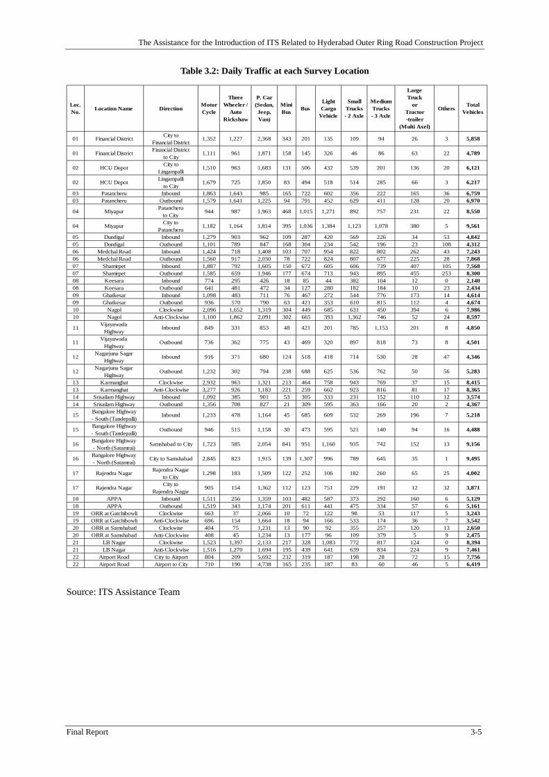
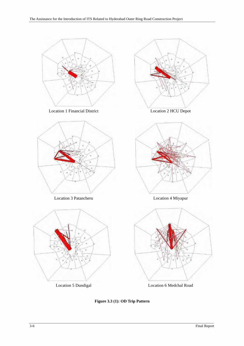
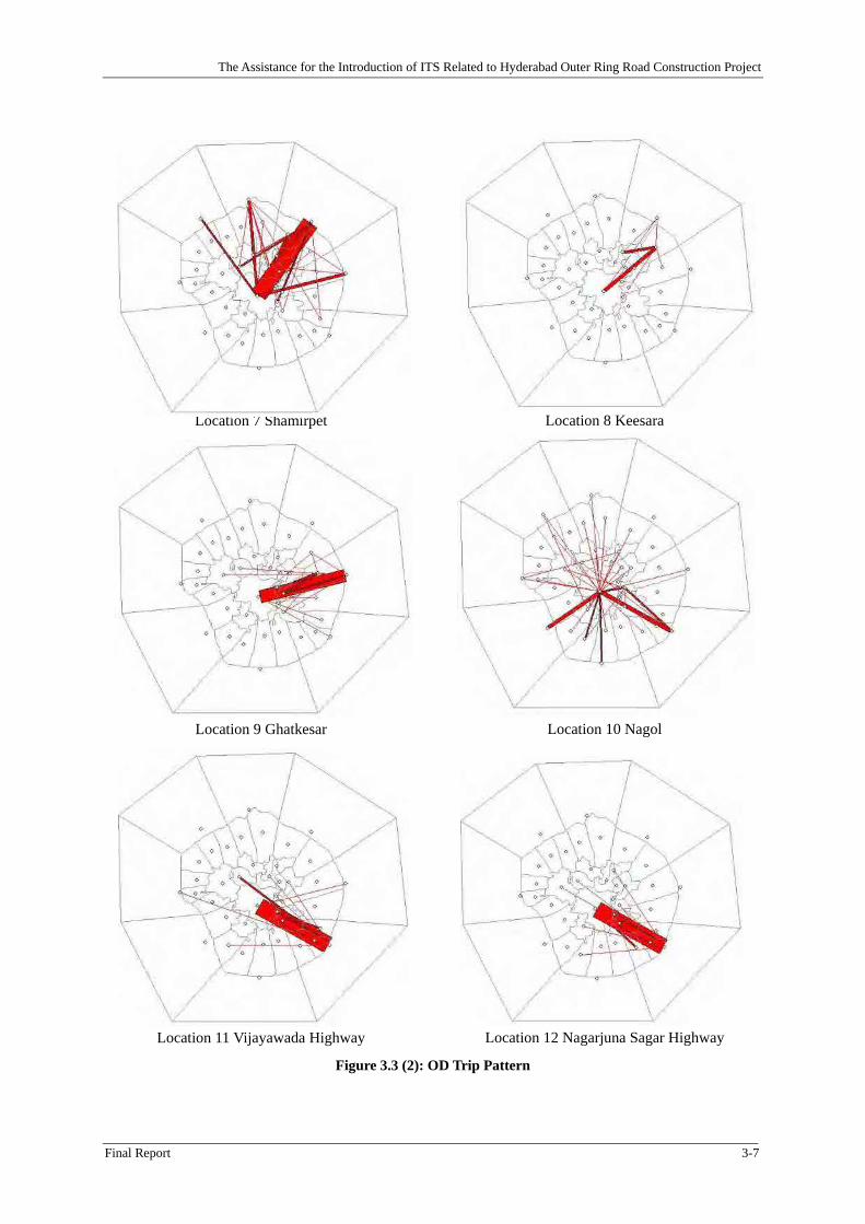
3.1.6 Traffic Survey Result
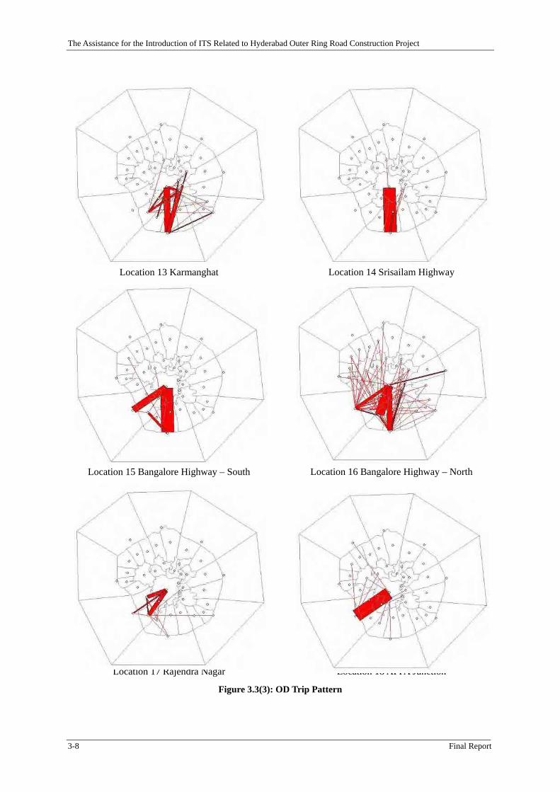
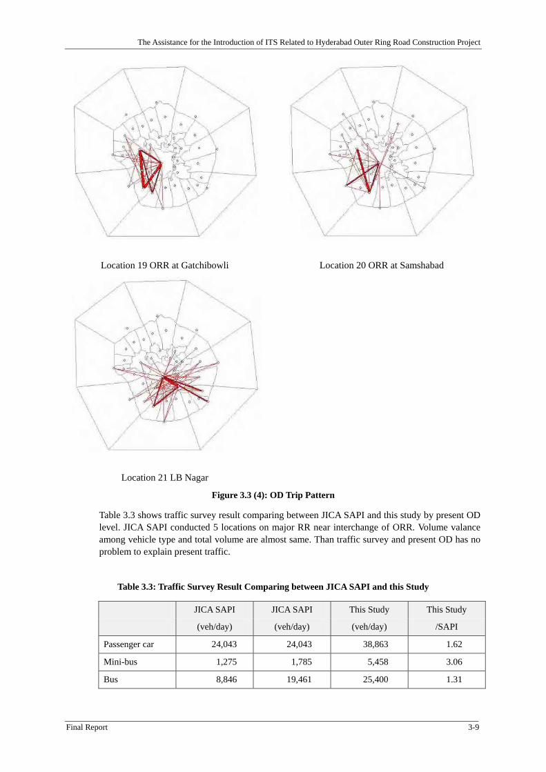
The traffic survey results are summarized in Table 3.2 and OD trip pattern of each survey locations is shown in Figure 3.3. Some of the observed characteristics are listed below.
Location 4, 6, 7, 10, 13, 16 and 21 are higher vehicle volume, more than 15,000 vehicles by both directions.
Daily average percentage of 2 & 3 wheeler is 34.3 %. Location 1, 3, 5, 8, 13 and 14 are higher rate more than 40 %. On the other hand, location 9, 11 and 22 with ORR tentative operating sections, location 19 and 20 are lower rate less than 25 %.
Daily average percentage of passenger vehicle except 2 & 3 wheeler is 37.0 %. Location 22 with ORR tentative operating sections, location 19 and 20 are higher rate more than 50 %. On the other hand, location 5, 8, 9, 11 and 13 are lower rate less than 30 %.
Daily average percentage of cargo vehicle is 28.3 %. Location 4, 6, 9, 11 and 12 are higher rate more than 35 %. On the other hand, location 1, 2, 3 and 22 are lower rate less than 25 %.
A damage of pavement is mainly by over loading cargo vehicles. These are usually “Medium Truck” and “Large Trucks or Tractor-Trailer” in this vehicle classification. Daily average percentage is 10.0 % of total volume. Location 9 and 11 are higher rate more than 20 %. On the other hand, location 1 and 22 are lower rate less than 5 %.
In OD Trip Pattern Figure 3.3, main desired movement is shown from/to city centre at each survey locations. This traffic survey was mainly carried out on RR at planning interchange location. Then, this desired movement is standard. On the other hand, other directional flows are displayed at location 4, 6, 13, 16, 19 and 20. Especially, location 19 and 20 are on ORR tentative operating section.
All of figure in Figure 3.3 are displayed as same scale. These figure have a tendency that southern locations than city centre have higher volume than northern locations. And main movement of southern locations is connecting between city centre and outer zone.
Survey locations were not located inside of the Inner Ring Road (IRR), it means traffic survey could not catch intra IRR volume as usual. And average trip length have longer tendency than intra city trips. In this study, present average trip length was 15.0 km. Especially, passenger car was 22.3 km.
The Assistance for the Introduction of ITS Related to Hyderabad Outer Ring Road Construction Project
The Assistance for the Introduction of ITS Related to Hyderabad Outer Ring Road Construction Project
3-6 Final Report
Location 1 Financial District
Location 3 Patancheru
Location 5 Dundigal
Location 2 HCU Depot
Location 4 Miyapur
Location 6 Medchal Road
Figure 3.3 (1): OD Trip Pattern
The Assistance for the Introduction of ITS Related to Hyderabad Outer Ring Road Construction Project
Final Report 3-7
Location 7 Shamirpet
Location 9 Ghatkesar
Location 11 Vijayawada Highway
Location 8 Keesara
Location 10 Nagol
Location 12 Nagarjuna Sagar Highway
Figure 3.3 (2): OD Trip Pattern
The Assistance for the Introduction of ITS Related to Hyderabad Outer Ring Road Construction Project
3-8 Final Report
Location 13 Karmanghat
Location 15 Bangalore Highway – South
Location 17 Rajendra Nagar
Location 14 Srisailam Highway
Location 16 Bangalore Highway – North
Location 18 APPA Junction
Figure 3.3(3): OD Trip Pattern
The Assistance for the Introduction of ITS Related to Hyderabad Outer Ring Road Construction Project
Final Report 3-9
Location 19 ORR at Gatchibowli
Location 21 LB Nagar
Location 20 ORR at Samshabad
Figure 3.3 (4): OD Trip Pattern
Table 3.3 shows traffic survey result comparing between JICA SAPI and this study by present OD level. JICA SAPI conducted 5 locations on major RR near interchange of ORR. Volume valance among vehicle type and total volume are almost same. Than traffic survey and present OD has no problem to explain present traffic.
Table 3.3: Traffic Survey Result Comparing between JICA SAPI and this Study
JICA SAPI JICA SAPI This Study This Study
(veh/day) (veh/day) (veh/day) /SAPI
Passenger car 24,043 24,043 38,863 1.62
Mini-bus 1,275 1,785 5,458 3.06
Bus 8,846 19,461 25,400 1.31
The Assistance for the Introduction of ITS Related to Hyderabad Outer Ring Road Construction Project
3-10 Final Report
LCV 3,264 4,570 16,447 3.60
Small truck 14,302 31,464 28,441 0.90
Medium truck 11,151 24,532 23,072 0.94
Large Truck 1,193 4,772 11,710 2.45
Total 64,074 110,627 149,391 1.35
Source: ITS Assistance Team
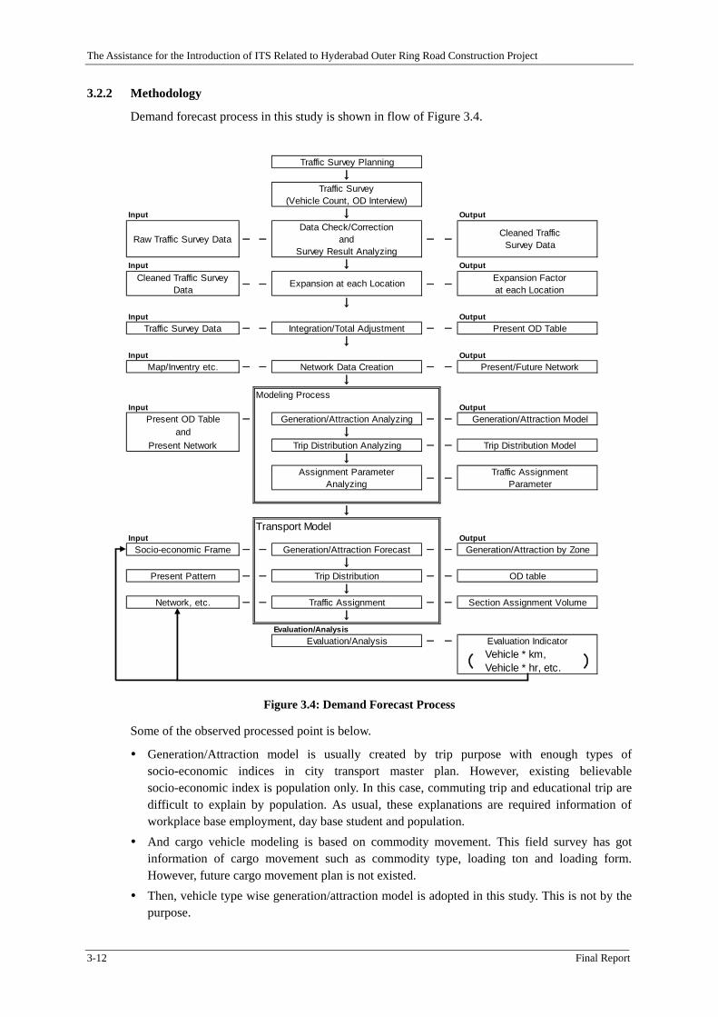
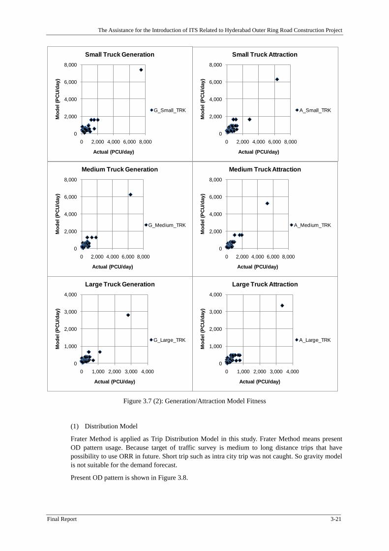
3.2 Traffic Demand Forecast
3.2.1 Pre-condition
Traffic demand was estimated under following pre-condition in this study.
Population data is only by CENSUS 2001 as present socio-economic data. HUDA master plan* 6 is only existing city master plan of Hyderabad indicates future
socio-economic frame as city/land use master plan up to 2020 based on CENSUS 2001. Even, HUDA master plan indicates population only as area wised socio-economic index.
Demand forecasts of previous studies were not estimated by categorized vehicle classification. It means by one vehicle type only. Even, those result values were not so clearly understood that 2 & 3 wheeler were included or excluded. And many previous studies were based that ORR is free toll expressway.
Demand forecasts of previous studies also estimated intra city volume including intra IRR volume. However, these were not estimated under exact present calibration. Because, no traffic surveyed data exists inside of IRR including IRR itself after 2002.
Demand forecasts of previous studies made network data matched with intra city traffic volume including ORR, RR, IRR and street/avenue. However, street/avenue level has difficulty to understand present condition including inventory information. Because, street/avenue level is not under a control of HGCL, and present situation is changing everyday by repairing and construction. Also, estimation of inside IRR is out of aim of this study.
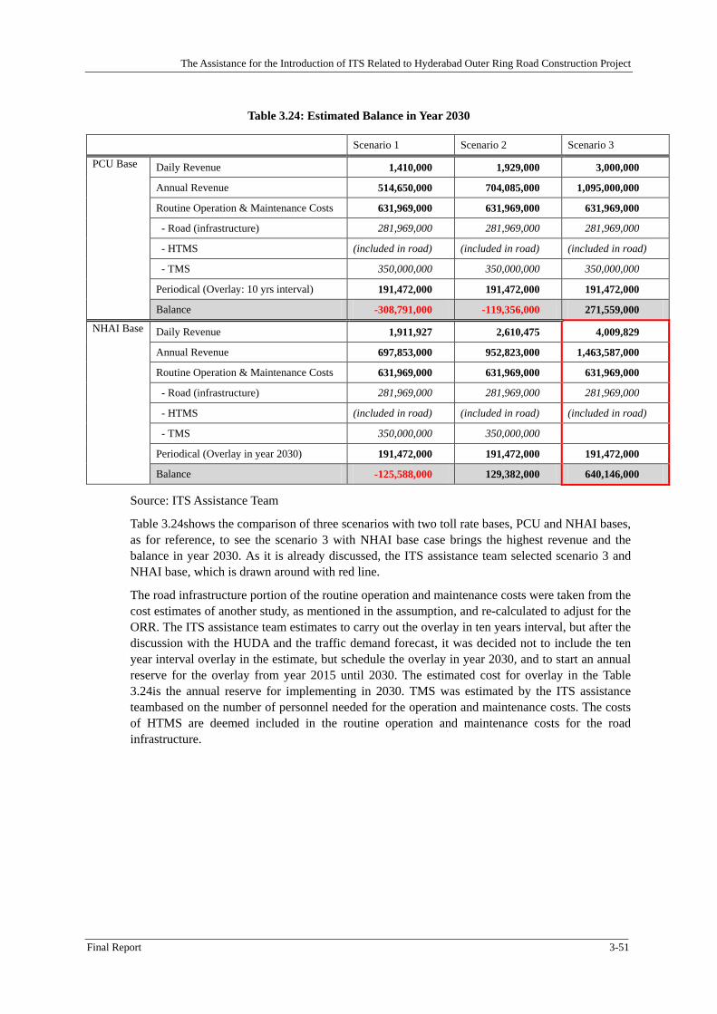
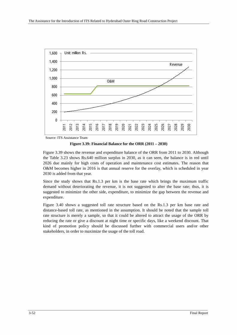
HGCL is considering levying toll by categorized vehicle types. It means estimated traffic volume should be by vehicle type.
HGCL is considering exclusion of 2 & 3 wheeler vehicles from ORR. Estimated ORR traffic volume is excluding 2 & 3 wheeler vehicles.
In this demand estimation, vehicle type wise Generation/Attraction model is adopted. In city transport planning, trip purpose wise demand forecast model is adopted. Purpose wise trip has characteristics, and main trip purposes of inside city are commute, education and home. These purposes almost cover 90 % of all trips as usual. By the way, ORR main use is not these purposes. This is by location and distance. ORR main use is long distance infrequently trip. And purpose wise Generation/Attraction model does not clearly estimate commodity vehicle. One of ORR purpose is supporting commodity vehicle and that through traffic shall not pass inside city.
In this demand estimation, incremental assignment is adopted. In city transport planning, equilibrium traffic assignment is adopted as usual. This aim for equilibrium between network capacity and total demand. However, this equilibrium assignment is not convenience in this study. Because, existing traffic volume inside IRR and IRR itself is not clearly understood and
*6 “A Plan for Sustainable Development, Hyderabad 2020, Draft Master Plan for Hyderabad Metropolitan Area, March 2006, HUDA” Hereinafter referred “HUDA Master Plan”.
The Assistance for the Introduction of ITS Related to Hyderabad Outer Ring Road Construction Project
Final Report 3-11
street/avenue level inventory is not clear. It means existing equilibrium is difficult to take between network capacity and total present movement.
In model process, all processes are estimated by Passenger Car Unit (Hereinafter referred “PCU”). And the PCU factors were obtained from the Indian Roads Congress (IRC) publication 106-1990 “Guidelines for Capacity of Urban Roads in Plain Areas”. PCU factor of each vehicle type is shown in Table 3.4.
Table 3.4: PCU Factor
Passenger car
Minibus Bus Light truck
Small truck
Medium truck
Large truck
PCU Factor
1.0 1.4 2.2 1.4 2.2 2.2 4.0
Source: Indian Road Congress
The Assistance for the Introduction of ITS Related to Hyderabad Outer Ring Road Construction Project
3-12 Final Report
3.2.2 Methodology
Demand forecast process in this study is shown in flow of Figure 3.4.
Traffic Survey Planning↓
Traffic Survey(Vehicle Count, OD Interview)
Input ↓ Output
Raw Traffic Survey Data - -
Data Check/Correctionand
Survey Result Analyzing- -
Cleaned TrafficSurvey Data
Input ↓ OutputCleaned Traffic Survey
Data - - Expansion at each Location - -Expansion Factorat each Location
↓Input Output
Traffic Survey Data - - Integration/Total Adjustment - - Present OD Table↓
Input OutputMap/Inventry etc. - - Network Data Creation - - Present/Future Network
Generation/Attraction model is usually created by trip purpose with enough types of socio-economic indices in city transport master plan. However, existing believable socio-economic index is population only. In this case, commuting trip and educational trip are difficult to explain by population. As usual, these explanations are required information of workplace base employment, day base student and population.
And cargo vehicle modeling is based on commodity movement. This field survey has got information of cargo movement such as commodity type, loading ton and loading form. However, future cargo movement plan is not existed.
Then, vehicle type wise generation/attraction model is adopted in this study. This is not by the purpose.
The Assistance for the Introduction of ITS Related to Hyderabad Outer Ring Road Construction Project
Final Report 3-13
3.2.3 Socio-economic Frame
The information for each of these zones was developed by utilizing the data in the HUDA Master Plan. The latest population data available was for the Year 2001 along with the historical decadal growth rates for each of the categories of the zones. The decadal growth rate was utilized in developing the population for the years 2010, 2020 and 2030. The area of each zone was available, which was utilized in assigning the population based on the population density for each of the zones.
Table 3.5shows Scenario 1 population development as trend case.
Table 3.5: Population Development as Scenario 1 (Trend Case)
Total Source: Population in 2001 and Area are by CENSUS 2001.
Growth Rate is by HUDA Master Plan
3.2.4 Scenarios
Three following scenarios are adopted under above-mentioned pre-condition in this study.
1) Scenario 1
Scenario 1 is a trend scenario following HUDA Master Plan.
2) Scenario 2
Scenario 2 is a scenario with development along ORR on both sides for 1 km width to the same level as city area. Same population density as average density of city area of traffic zone 1 - 13.
3) Scenario 3
Scenario 3 is same as Scenario 2 taking congestion on IRR into consideration. Socio-economic frame is same as Scenario 2. In this Scenario 3, future IRR congestion is applied average
The Assistance for the Introduction of ITS Related to Hyderabad Outer Ring Road Construction Project
3-14 Final Report
estimated traffic volume in “Evaluating Financing Alternatives for Phase IIB of Hyderabad Outer Ring Road Project, Indian Institute of Technology Madras, Chennai 600 036, January 2008”. The IRR estimated volume shows in Table 3.6.
Table 3.6: Traffic volumes estimated in AADT (PCU/day) for all the scenarios
Total 9,631,489 16,808,094 32,684,025 9,631,489 16,808,094 32,684,025
ZonePopulation in Scenario 1 Population in Scenario 2 and 3
Source: ITS Assistance Team
3.2.5 Network
Present network and future network in 2020 and 2030 are shown in Figure 3.5 and Figure 3.6. Also inventories of ORR, RR and IRR are shown in Table 3.8, Table 3.9, and Table 3.10.
About road capacity estimation, road capacity of the Indian Roads Congress (IRC) publication 106-1990 “Guidelines for Capacity of Urban Roads in Plain Areas” was applied.
Differences of road network between present and future are implementation of ORR, approved RR widening and implementation.
The Assistance for the Introduction of ITS Related to Hyderabad Outer Ring Road Construction Project
3-16 Final Report
Figure 3.5: Present Network
Figure 3.6: Future Network
The Assistance for the Introduction of ITS Related to Hyderabad Outer Ring Road Construction Project
Same as ExistingSame as ExistingSame as ExistingSame as ExistingSame as ExistingSame as ExistingSame as ExistingSame as Existing
Same as Existing
SectionName Segment - From Segment - To
Present Condition Future Condition
Same as ExistingSame as ExistingSame as ExistingSame as Existing
Source: HGCL and the Indian Roads Congress (IRC) publication 106-1990 “Guidelines for Capacity of Urban Roads in Plain Areas”
3.2.6 Models
(1) Generation/Attraction Model
Generation/Attraction model formula by each vehicle type is as follows, and parameters of each vehicle type are shown in Table 3.11. In this model, some of the observed are applied ORR_Flag, OuterFlag and SouthFlag.
Traffic zones in this study are categorized 3 areas;
4) Developed City Area: zone 1-13
5) Sub-urban/Rural Area: zone 14-33
6) Outer Area: zone 51-58
Explanation of these areas in model applies these 3 flags. ORR_Flag explains ORR located area as zone 14-33. OuterFlag explains outer area as zone 51-58.
Southern outer area of study area has remarkably higher traffic than northern outer area indicated by traffic survey. Then SouthFlag explains southern area as zone 55-57
GA = Pop x a1 + ORR_Flag x a2 + OuterFlag x a3 + SouthFlag x a4 + b
Legend
GA: Generation/Attraction (PCU/day)
Pop: Population
ORR_Flag : Flag of ORR located zone
OuterFlag: Outer zone Flag
SouthFlag: Southern zone Flag
The Assistance for the Introduction of ITS Related to Hyderabad Outer Ring Road Construction Project
The Assistance for the Introduction of ITS Related to Hyderabad Outer Ring Road Construction Project
3-20 Final Report
Figure 3.7 (1): Generation/Attraction Model Fitness
0
5,000
10,000
15,000
0 5,000 10,000 15,000
Mod
el (P
CU/d
ay)
Actual (PCU/day)
Passenger Car Generation
G_PC
0
5,000
10,000
15,000
0 5,000 10,000 15,000
Mod
el (P
CU/d
ay)
Actual (PCU/day)
Passenger Car Attraction
A_PC
0
500
1,000
1,500
2,000
0 500 1,000 1,500 2,000
Mod
el (P
CU/d
ay)
Actual (PCU/day)
Mini Bus Generation
G_Mini_Bus
0
500
1,000
1,500
2,000
0 500 1,000 1,500 2,000
Mod
el (P
CU/d
ay)
Actual (PCU/day)
Mini Bus Attraction
A_Mini_Bus
0
2,000
4,000
6,000
8,000
0 2,000 4,000 6,000 8,000
Mod
el (P
CU/d
ay)
Actual (PCU/day)
Bus Generation
G_Bus
0
2,000
4,000
6,000
8,000
0 2,000 4,000 6,000 8,000
Mod
el (P
CU/d
ay)
Actual (PCU/day)
Bus Attraction
A_Bus
0
2,000
4,000
6,000
0 2,000 4,000 6,000
Mod
el (P
CU/d
ay)
Actual (PCU/day)
Light Truck Generation
G_Light_TRK
0
2,000
4,000
6,000
0 2,000 4,000 6,000
Mod
el (P
CU/d
ay)
Actual (PCU/day)
Light Truck Attraction
A_Light_TRK
The Assistance for the Introduction of ITS Related to Hyderabad Outer Ring Road Construction Project
Final Report 3-21
Figure 3.7 (2): Generation/Attraction Model Fitness
(1) Distribution Model
Frater Method is applied as Trip Distribution Model in this study. Frater Method means present OD pattern usage. Because target of traffic survey is medium to long distance trips that have possibility to use ORR in future. Short trip such as intra city trip was not caught. So gravity model is not suitable for the demand forecast.
Present OD pattern is shown in Figure 3.8.
0
2,000
4,000
6,000
8,000
0 2,000 4,000 6,000 8,000
Mod
el (P
CU
/day
)
Actual (PCU/day)
Small Truck Generation
G_Small_TRK
0
2,000
4,000
6,000
8,000
0 2,000 4,000 6,000 8,000
Mod
el (P
CU
/day
)
Actual (PCU/day)
Small Truck Attraction
A_Small_TRK
0
2,000
4,000
6,000
8,000
0 2,000 4,000 6,000 8,000
Mod
el (P
CU
/day
)
Actual (PCU/day)
Medium Truck Generation
G_Medium_TRK
0
2,000
4,000
6,000
8,000
0 2,000 4,000 6,000 8,000
Mod
el (P
CU
/day
)
Actual (PCU/day)
Medium Truck Attraction
A_Medium_TRK
0
1,000
2,000
3,000
4,000
0 1,000 2,000 3,000 4,000
Mod
el (P
CU
/day
)
Actual (PCU/day)
Large Truck Generation
G_Large_TRK
0
1,000
2,000
3,000
4,000
0 1,000 2,000 3,000 4,000
Mod
el (P
CU
/day
)
Actual (PCU/day)
Large Truck Attraction
A_Large_TRK
The Assistance for the Introduction of ITS Related to Hyderabad Outer Ring Road Construction Project
3-22 Final Report
Figure 3.8: Frater Pattern by Traffic Survey
3.2.7 Traffic Assignment
Incremental assignment is adopted in this demand forecast explained in Pre-condition chapter. Medium/Long distance trip route choice is very closed to demand assignment. In this traffic assignment, assignment rates of increment are applied 50%, 20%, 10%, 10% and 10%.
3.2.8 Result of Demand Forecast
(1) OD Table
Calibrated present OD desired line is shown in Figure 3.9. In calibration process, daily average volume is calculated by trip frequency interviewed result.
Figure 3.9: Present OD Desired Line made by Traffic Survey in 2010
The Assistance for the Introduction of ITS Related to Hyderabad Outer Ring Road Construction Project
Final Report 3-23
OD Table in 2015 (Scenario 1)
OD Table in 2020 (Scenario 1)
OD Table in 2030 (Scenario 1)
OD Table in 2015 (Scenario 2)
OD Table in 2020 (Scenario 2)
OD Table in 2030 (Scenario 2)
Figure 3.10: Future OD Desired Line by each Scenario
The Assistance for the Introduction of ITS Related to Hyderabad Outer Ring Road Construction Project
3-24 Final Report
(2) Traffic Assignment
Calibrated present daily average link volume is shown in Figure 3.11. And future volume in 2030 shown as future maximum volume case in Figure 3.12.
Figure 3.11: Present Daily Average Traffic Volume in 2010
Figure 3.12: ORR Maximum Volume Case in 2030 (Scenario 3, without toll)
(3) Sensitivity Analysis for ORR Toll
The Assistance for the Introduction of ITS Related to Hyderabad Outer Ring Road Construction Project
Final Report 3-25
Methodology of sensitivity analysis is orthodox to estimate demand and revenue fluctuation by changing toll under same OD table and network in each scenario. Usually, demand has reducing trend with increasing toll rate. On the other hand, total revenue fluctuation does not have same trend with demand itself. In the first phase, total revenue will increase with higher toll rate. On the contrary in the second phase, total revenue will decrease with higher toll rate. Between these phases, fluctuation has a peak, it explain maximum total revenue under a scenario.
In each scenario, maximum revenue cases were analyzed by sensitivity analysis by toll rate. 0.8 Rupees/km is maximum revenue case in Scenario 1 and 2. On the other hand, Scenario 3 maximum revenue case is 1.3 Rupees/km.
Rs.1,300,000
Rs.1,400,000
Rs.1,500,000
0.6 0.7 0.8 0.9 1.0
Dai
ly T
otal
Rev
enue
Toll Rate (Rupee/km)
Toll Revenue (Scenario 1)
Figure 3.13: Sensitivity Analysis for ORR Toll (Scenario 1)
Rs.1,700,000
Rs.1,800,000
Rs.1,900,000
Rs.2,000,000
0.6 0.7 0.8 0.9 1.0
Dai
ly T
otal
Rev
enue
Toll Rate (Rupee/km)
Toll Revenue (Scenario 2)
Figure 3.14: Sensitivity Analysis for ORR Toll (Scenario 2)
Figure 3.15: Sensitivity Analysis for ORR Toll (Scenario 3)
(2) Summary of Demand Forecast
Future demand forecast results as maximum revenue case in each Scenario are shown in Figure 3.16 through Figure 3.18. ORR minimum traffic volume and minimum revenue scenario is Scenario 1, trend case. In Scenario 3 of IRR congestion consideration, ORR demand and revenue is higher than other scenarios.
The Assistance for the Introduction of ITS Related to Hyderabad Outer Ring Road Construction Project
3-26 Final Report
Scenario 1 in 2015, ORR Toll: 0.8 Rupee/km
Scenario 2 in 2015, ORR Toll: 0.8 Rupee/km
Scenario 3 in 2015, ORR Toll: 1.3 Rupee/km
Figure 3.16: Future Traffic Volume in 2015
The Assistance for the Introduction of ITS Related to Hyderabad Outer Ring Road Construction Project
Final Report 3-27
Scenario 1 in 2020, ORR Toll: 0.8 Rupee/km
Scenario 2 in 2020, ORR Toll: 0.8 Rupee/km
Scenario 3 in 2020, ORR Toll: 1.3 Rupee/km
Figure 3.17: Future Traffic Volume in 2020
The Assistance for the Introduction of ITS Related to Hyderabad Outer Ring Road Construction Project
3-28 Final Report
Scenario 1 in 2030, ORR Toll: 0.8 Rupee/km
Scenario 2 in 2030, ORR Toll: 0.8 Rupee/km
Scenario 3 in 2030, ORR Toll: 1.3 Rupee/km
Figure 3.18: Future Traffic Volume in 2030
The Assistance for the Introduction of ITS Related to Hyderabad Outer Ring Road Construction Project
Final Report 3-29
In case of Scenario1 in 2030, ORR section demand is 3,500 - 18,400 PCU/day. In Scenario 2, ORR section demand is 5,200 - 24,900 PCU/day. In Scenario 3, ORR section demand is 2,200 - 26,800 PCU/day
Daily revenue is 1.4 million Rupees in Scenario1, 1.9 Rupees in Scenario 2 and 3.0 million Rupees in Scenario 3.
3.2.9 Recommendation
Maximum demand and revenue case is 1.3 Rupees/km of toll rate in Scenario 3. However, traffic volume inside of IRR and IRR itself are not clearly understood at this moment by following reason.
• After 2002, traffic survey is not conducted inside of IRR and IRR itself.
• Latest population in study area was by 2001 census. Already 9years past.
In previous studies, intra city traffic volume was estimated. By the way, difficulty of present calibration is easy to image in these studies. And socio-economic data usage has also difficulty as model input by existing socio frame condition.
In 2011, new census shall be approved at India. Re-estimation of ORR traffic demand is recommended after 2011 census as city transport master plan with traffic survey inside IRR and IRR itself.
The Assistance for the Introduction of ITS Related to Hyderabad Outer Ring Road Construction Project
3-30 Final Report
3.3 Toll Rate Setting
3.3.1 Roadside Interview Survey
The interview survey was conducted along with the traffic count survey and origin-destination (OD) survey at the designated roadsides. (Source: ITS Assistance Team
Figure 3.19) The survey method was closed-questionnaire interview survey to drivers.
The objective of the survey was to determine the origin-destination of the road users, their preference to using the ORR, and willingness to pay toll. Figure 3.20 shows the zone map used for the OD data collection and the Table 3.12shows the points of the survey and the dates. Data was not obtained from 2-wheelers and 3-wheelers as these two categories of vehicles are not permitted to use the ORR.
Source: ITS Assistance Team Figure 3.19: Location of the Opinion Survey
(1) Locations:
The data was collected at 21 locations as the above map shows. The map identifies the interchanges of the ORR with the Radial Roads in Grey color (with numbers 1 to 19), and two additional locations (20 and 21) along the ORR. The exact locations of the data collection are identified with Red Color circles. It can be observed that a few locations (4, 10, 13, 15 and 21) were not collected at the interchanges or the original planned locations, as such interchanges did
The Assistance for the Introduction of ITS Related to Hyderabad Outer Ring Road Construction Project
Final Report 3-31
not exist or there was no traffic movement at the original location.
The details of the locations are noted below in Table 3.12 along with the dates of the data collection.
Table 3.12: Location and Date of Opinion Survey
Location Name Specific Detail Survey Date
1. Financial District On Radial Road 33, just south of RR 6 Apr. 15, 2010
2. HCU Depot On RR 6, just west of RR 7 Apr. 16, 2010
3. Patancheru On National Highway 9 at the Toll Plaza Apr. 16, 2010
4. Miyapur On RR 9 (NH 9), just west of RR 32 Apr. 16, 2010
5. Dundigal On SH Narsapur Road, just north of ORR Apr. 13, 2010
6. Medchal Road On RR 12, just south of ORR Apr. 13, 2010
7. Shamirpet On SH Karimnagar Road, just north of ORR Apr. 7, 2010
8. Keesara RR 16, just west of ORR Apr. 22, 2010
9. Ghatkesar RR 19, just west of ORR Apr. 22, 2010
10. Nagol Along Inner Ring Road near proposed RR 20 & 21 Apr. 23, 2010
11. Vijayawada Highway RR 24, just east of ORR Apr. 21, 2010
12. Nagarjuna Sagar Highway RR 25, just south of ORR Apr. 22, 2010
13. Karmanghat Along IRR, just west of RR 26 Apr. 23, 2010
14. Srisailam Highway On Srisailam Highway, just south of ORR Apr. 21, 2010
15. Bangalore Highway – South (Tandepalli)
On NH 7, south of airport junction Apr. 20, 2010
16. Bangalore Highway – North (Satamrai)
On NH 7, north of airport junction Apr. 20, 2010
17. Rajendra Nagar On RR 2, just west of IRR Apr. 21, 2010
18. APPA Junction On RR 3, just east of ORR Apr. 15, 2010
19. ORR at Gatchibowli On ORR, just south of RR 6 Apr. 15, 2010
20. ORR at Samshabad On ORR, just west of airport junction Apr. 20, 2010
21. LB Nagar Along IRR, between RR 24 and 25 Apr. 23, 2010
Source: ITS Assistance Team
(2) Methodology
The data collection included stopping vehicles and asking the respondents all the questions from the questionnaire. All locations were planned such that it would be comfortable to stop vehicles without obstructing the movement of traffic. Permission was obtained from local police before commencing the data collection.
All data was obtained for 24-hours continuously at each location. The following shifts were utilized for the data collection:
Shift 1: 06:00 - 12:00
The Assistance for the Introduction of ITS Related to Hyderabad Outer Ring Road Construction Project
3-32 Final Report
Shift 2: 12:00 - 18:00
Shift 3: 18:00 - 00:00
Shift 4: 00:00 - 06:00
Each shift included four personnel per direction of traffic, and additional personnel were provided for assistance and coordination. There was no rain or other outward incidents, which could have affected the data collection.
Training sessions were conducted for all data collectors and supervisors. A mock exercise was conducted, and all personnel were assessed. After the trainings, a series of surveys were conducted and all data collectors were monitored by a supervisor. Data coordinators were appointed to coordinate with the supervisors, data collectors, support staff, and other personnel to ensure that all work proceeded as planned, and with the desired quality. All data collectors were provided with additional personnel for relief during their shifts for breaks. Upon completion of the data collection, all forms with incomplete data or inaccurate data (such as checking multiple options, mentioning same entrance/exit on the ORR, etc.) were discarded. Following to the data cleaning, the verified forms were entered into a database, and all data was verified for accuracy of data entry. The data in the database was reviewed again to sort out inaccurate data.
(3) Methods of Questioning:
The following shows the methods of the questioning:
Respondents
Most of the respondents in the cars were the drivers of the cars. In some cases, the passengers chose to answer the questions instead of the drivers (usually this corresponded to the case when the driver of the car was chauffeuring the passenger)
Most of the respondents for the Mini Bus/Bus were the conductors of the bus, and only in a few cases the drivers chose to respond. In some cases, the passengers of the bus chose to answer the questions.
For the trucks and commercial vehicles, most of the respondents were the drivers, and only a few times, the passengers responded to the questions.
Sex of the respondent was entered
Age rank of the respondent was entered per the range of the questionnaire. Very few respondents denied responding to the age, in which case their age was entered in the unknown option.
Occupation was entered based on the options provided. Several respondents were in the Information Technology sector, and chose to opt for the non-defined option.
Several of the respondents chose to select multiple options for the Type of Business. However, they were asked to choose only one option, in which case they chose the option that best suited their activity. It was observed that several respondents chose to select unemployed option, even though it was noticed that they were driving commercial vehicles. However, the typical response was that they were only engaged for temporary basis or daily wages for a short period of time, and they chose to select the unemployed option.
The monthly income was entered per the range provided in the questionnaire. It was observed that several of the unemployed people had a good income per month, and to which they responded that the income was not based on their work, but was due to other sources (such as rental income, shares, parental support, etc.)
Most of the respondents had an own vehicle. Other motorized vehicles included 3-wheelers,
The Assistance for the Introduction of ITS Related to Hyderabad Outer Ring Road Construction Project
Final Report 3-33
trucks, tractors, construction vehicles, etc.
Trip Purpose
School responded to school, college, tuition, coaching classes, etc., and was also selected by a few adults who were traveling for the purpose of picking up/dropping off their children, or who were teachers/professors
Sightseeing was selected by tourist or non-local residents who were not in the city for business, but was also selected as an option by a few people who were not working that day, and chose to spend the day out of their regular work day
Several respondents chose “the other” option which corresponded to several trip purposes such as entertainment/movies, maintenance/repairs of their vehicle, meals, shopping (including casual/retail), visiting friends, family, weddings and functions
The origin was identified as the starting point of their trip, and the destination as the ending point of the trip. In cases where it was difficult for the respondent to select their origin and/or destination with the zone map, they were asked to state their place name, and the surveyors filled in the zone number based on their knowledge of the area, which was verified by the supervisors.
The trip frequency corresponded for the same purpose of this trip, and was selected per the frequency of the questionnaire. Some respondents chose other frequency which primarily corresponded to several times a month.
The number of hours for the trip was identified as the time between the origin and the destination. However, a few respondents stated that they had multiple trip purposes, and considered all their errands as a single trip, which led them to provide more than eight hours for the trip within the city.
The loading capacity was provided by several respondents, but it was observed that some of the responses were higher than the capacity for that category of vehicle, leading to the belief that such vehicles were overloading their trucks.
Several respondents chose to drive the ORR as their preference. Their responses corresponded to the ORR entrances / exits not necessarily close to the location of the survey, as they stated that they would travel the ORR primarily in those sections
Most respondents felt that the questions "how much would be adequate amount for the toll fee" and "how much would be the highest amount that you think is acceptable" were the same, and chose to provide the same amount for the two questions.
Most of the respondents chose to provide ten (10) Rupees as a maximum toll rate. Only a few respondents, especially in the affluent parts of the city, chose to pay higher toll. It was also observed that most respondents considered the cost as of higher importance than the travel time, which was evident that they were willing to pay Rs. 20 to save 15 minutes, but were not willing to pay Rs. 40 to save 30 minutes of travel time.
(4) Results of the Opinion Survey
The total number of the respondents is 12,002 respondents, of which 98% of the respondents are male and merely 1.8% is female. According to the survey company, the reason behind of this is because woman drivers are not prevailing in Hyderabad. As it shows in the Table 3.13, the age brackets of 25-30 and 31-34 are the major respondents of this survey.
The Assistance for the Introduction of ITS Related to Hyderabad Outer Ring Road Construction Project
3-34 Final Report
Table 3.13: Sex and Age
Age/Sex Female Male Total
15-19 10 261 271
20-24 33 1,160 1,193
25-30 44 3,120 3,164
31-34 33 3,140 3,173
35-40 19 1,849 1,868
41-44 10 1,029 1,039
45-49 9 553 562
50-54 8 468 476
55-59 3 204 207
60> 1 46 47
Unknown 0 2 2
Total 170 11,832 12,002
Source: ITS Assistance Team (N=12,002)
Source: ITS Assistance Team (N=12,001)
Figure 3.20: Sex and Age
Figure 3.21 shows the age bracket and business type. More than a quarter of respondents are categorized in “non-defined activities,” which are presumably commercial business or any other service business, or unemployed.
Figure 3.22 shows the age bracket and income distribution. As it shows, majority of respondents fall into the income rage between Rs5,001 and 10,000, followed by Rs.10,000 and 15,000. The income range up to Rs.15,000 consists of nearly 70% of the respondents.
0
500
1,000
1,500
2,000
2,500
3,000
3,500
Male
Female
The Assistance for the Introduction of ITS Related to Hyderabad Outer Ring Road Construction Project
Final Report 3-35
Source: ITS Assistance Team(N=12,001)
Figure 3.21: Age Bracket and Business Type
Source: ITS Assistance Team(N=12,001)
Figure 3.22: Age Bracket and Income
Figure 3.23 shows the occupation and income distribution. It needs careful interpretation since almost all occupation except self-employed and unemployed show the similar pattern of income distribution, which is quite incomprehensive considering around 30% of “director/president/board member” earn less than Rs.10,000, while nearly 80% of unemployed earned less than Rs.10,000 per month, as well.
0% 10% 20% 30% 40% 50% 60% 70% 80% 90% 100%
15-19
20-24
25-30
31-34
35-40
41-44
45-49
50-54
55-59
60>
Agriculture MiningManufacturing Electricity, Gas, WaterConstruction Wholesale, Retailsale and HospitalityTransportation, Communiction and Wahrehousing Finance, Insurance and EstatePublic Service, Formal Services StudentHousewife Non-defined Activities
The Assistance for the Introduction of ITS Related to Hyderabad Outer Ring Road Construction Project
3-36 Final Report
According to the survey, the share of unemployment is around one third of the total respondents, while not-defined is one fourth. From these results, it is assumed that student and housewife are included in the category of unemployment in the business type. However it is still strange that one quarter of unemployed earn more than Rs.10,000 per month, which is around 8% to the total respondents.
Source: ITS Assistance Team(N=12,001)
Figure 3.23: Occupation and Income
Source: ITS Assistance Team(N=12,001)
Figure 3.24: Income and Number of Vehicle owned
Figure 3.24shows the number of vehicle (4-wheeled car) owned by the respondents’ income distribution. The survey shows that three-quarter of respondents own at least one vehicle. It should be noted that even the lowest income stratum, Rs.0 – 5,000, above one quarter of respondents,
The Assistance for the Introduction of ITS Related to Hyderabad Outer Ring Road Construction Project
Final Report 3-37
own a vehicle, which proportion is equivalent to 8% to the total number of respondents. The incident could be explained from the business practice in India that even a low income household can finance to buy a vehicle by getting a bank loan, interest rate of which is set quite low, as long as the household has stable monthly income. Besides that, it should be noted that the survey did not ask respondent’s total household income, but merely asked his/her monthly income, so a combined household income is unknown nor the ownership, either it is respondent’s vehicle or a family member is also not clear from the questionnaire.
There is no significant difference in the number of vehicle up to the first one, but from the second car, it is observed that the higher the income brackets, more vehicles are owned.
Source: ITS Assistance Team(N=12,001)
Figure 3.25: Business Type and Vehicle Type for Trip
Source: ITS Assistance Team(N=12,001)
Figure 3.26: Business Type and Trip Purpose
The Assistance for the Introduction of ITS Related to Hyderabad Outer Ring Road Construction Project
3-38 Final Report
Source: ITS Assistance Team(N=12,001)
Figure 3.27:: Occupation and Trip Purpose
Figure 3.25 shows the business type and the vehicle type that they use for the trip at the survey. From nearly 40% to above 60% of the respondents use sedan and/or taxi for their trip, followed by bus and light cargo, 11% on the average, and medium truck, 10% on the average. From the result, it should be fair to say that the major transportation mode in Hyderabad is a passenger car or taxi, and public transportation is not prevailing yet.
Figure 3.26 shows the business type and the respondents’ trip purposes. Business is the most selected purpose for almost all business type except transportation and non-defined. The difference between “commuting” and “business” is that if a respondent is going out to have a business meeting or to visit its customers, it is counted as “business,” while if he is going to his company, it is considered as “commuting.” It is understandable if the respondents’ attribution is transportation, they answered the purpose of the trip as “bus, truck and taxi driver” meaning they are driving a commercial vehicle. But according to the result, “bus, truck and taxi driver” is seen in all business types; in particular, that in non-defined is quite noticeable.
Figure 3.27 shows the occupation and the respondents’ trip purposes. The similar patterns in Figure 3.26 are observed in this figure, as well. Although “business” is the majority of the trip purpose, “bus, truck and taxi driver” is noticeable in self-employed and unemployed, which is incomprehensible, in particular, in the categories of “director/president/board member” and “manager/general manager.”
The answer “others” consist of meal, car maintenance, visiting friends and relatives, visiting entertainment facilities and shopping, in order of descending prevalence.
Table 3.14 shows the type of vehicle used for the trip made by the respondents. About a half of respondents used a passenger car, followed by small truck, light cargo vehicle and medium truck. The total users of mini-bus and bus are about 15%. Considering the future population growth and the easiness for applying for a loan to purchase a car in India, even for the people in the low income strata, it is presumed that the number of passenger car will increase significantly.
The Assistance for the Introduction of ITS Related to Hyderabad Outer Ring Road Construction Project
Final Report 3-39
Table 3.14: Vehicle Type
Vehicle Type Percentage
Sedan/Taxi/Jeep/Van 46.71 %
Mini-bus 4.16 %
Bus 9.90 %
Light Cargo Vehicle (LCV) 11.40 %
Small Truck (2 Axles) 12.32 %
Medium Truck (3 Axles) 10.50 %
Large Truck (Multi-Axles or tractor-trailer) 4.07 %
Others Motorized Vehicle 0.94 %
Total 100.00 %
Source: ITS Assistance Team(N=12,001)
Source: ITS Assistance Team(N=12,001)
Figure 3.28: Trip Purpose and Vehicle Type
Figure 3.28 shows the cross-tabulation of trip purpose and vehicle type. As it shows, the major vehicle type for all the trip purposes is sedan, taxi, jeep and van, followed by bus, light cargo vehicle and small truck.
The result of trip purpose indicates that bus, truck and taxi driver is 32%, for business is 27%, and for comminuting/work is 12%, which imply, together with Figure 3.28, that the share of business using a passenger vehicle is quite significant, after that of bus, truck and taxi driver. It should be also noted that nearly a half of trip purpose falls under commuting to work and school and business objectives; therefore, when the toll road operation sets the toll rate, it is suggested to take into account the daily-use users’ opinions and should be favorable to their daily usage, if the usage of toll road is applicable to their trip patterns.
The Assistance for the Introduction of ITS Related to Hyderabad Outer Ring Road Construction Project
3-40 Final Report
April 2010 January 2009
Source: ITS Assistance Team Source: SAPI for Hyderabad ORR Project Phase I (May 2009)(N=12,001) (N=9,399)
Figure 3.29: Vehicle Type and Trip Purpose (Comparison between 2009 and 2010)
Figure 3.29 shows the comparison of the vehicle type and trip purpose between the survey in January 2009 and April 2010. They show quite different patterns, even though the second survey, conducted in April 2010, was merely carried out within one year after the first survey; however, it should be taken into consideration that the survey points and the classification of vehicle types are slightly different between two surveys.
The respondents of the first survey answered that 50% of them used minibus for commuting for offices and schools, but recent survey shows only 25%, a half of that of the first survey, use mini bus for that purpose. The share of the trip purposes among the vehicle types show almost same patterns in the recent survey result, but they are quite different in those in year 2009 survey. Besides that, the proportion of “bus, truck and taxi driver” is quite sizeable in all vehicle types in the year 2010 survey, which seems to be quite incomprehensible.
Table 3.15: Willingness to Use the ORR (Toll Road)
Number Percentage
Yes 6,557 54.6%
No 5,445 45.4%
Total 12,002 100.0%
Source: ITS Assistance Team(N=12,002)
Table 3.15shows the willingness of the respondents who would most probably use the ORR instead of general roads, with the conditions that the toll road speed limit is maximum 120km/hrto get their destinations. At the survey, the respondents were shown the proposed ORR map to make sure they understand the alignment of the ORR. The result shows that respondents who are willing to pay for the ORR reaches slightly more than a half of the respondents. Compared to the previous survey, the ratio decreases significantly from 89.6% to 54.6%.
The Assistance for the Introduction of ITS Related to Hyderabad Outer Ring Road Construction Project
Final Report 3-41
Source: ITS Assistance Team (N=12,002 in year 2010, N=7,545 in year 2009)
Figure 3.30: Comparison of the Willingness to Pay by the Type of Vehicle
Figure 3.30shows the comparative results of the willingness to pay for taking the ORR to get respondents’ destinations. In the previous survey, “Bus” and “Others” were not available as the options, so the data is blank in the figure. As shown, the willingness to pay in the survey results in 2009 exceeds in all vehicle types, compared to those in year 2010. The previous survey shows that the respondents driving commercial vehicles, such as mini bus, light cargo vehicle and trucks are more willing, more than 80% for those categories, to pay for extra money for saving their time. It is unknown why the results in 2010 are worsen after just one year from the previous survey, but it should be noted that the willingness to pay for toll road has deteriorated to some extent, whether it’s significance is big or not, so the toll road operator should keep in mind when it set out the toll rates.
Source: ITS Assistance Team (N=12,002)
Figure 3.31: Trip Frequency between the O-D for the same Trip Purpose
0% 20% 40% 60% 80% 100%
Sedan/Jeep/Van
Mini Bus
Bus
Light Cargo Vehicle
Small Truck
Medium Truck
Large Truck
Others
2010
2009
43.2%
22.4%
14.1%
11.6%
4.7% 4.0%
Every day
Every weekday
1-2 times per week
1-2 times per month
1-2 times per year
Others
The Assistance for the Introduction of ITS Related to Hyderabad Outer Ring Road Construction Project
3-42 Final Report
Figure 3.31 shows trip frequency between the O-D for the same trip purpose taken by the respondents. As it shows, more than 65% of the respondents pass the same route almost every day or every weekday.
Source: ITS Assistance Team (N=12,002)
Figure 3.32: Trip Frequency and Willingness to Pay for the ORR
Figure 3.32shows the cross-tabulation of the trip frequency and the willingness to pay for the ORR. As the result shows, the frequency does not much affect the willingness to pay for using the toll road. Even the every-day users and 1-2 times per year users have almost same correspondence to the willingness to pay for the usage of the ORR.
Source: ITS Assistance Team (N=12,002)
Figure 3.33: Willingness to Pay by Income Strata
Figure 3.33shows the willingness to pay by income strata. As the result shows, there is no significant difference observed for the willingness to pay by the respondents’ income strata.
0% 20% 40% 60% 80% 100%
Every day
Every weekday
1-2 times per week
1-2 times per month
1-2 times per year
Others
Yes
No
0 1,000 2,000 3,000 4,000 5,000 6,000
0 - 5,000
5,001 - 10,000
10,001-15,000
15,001 - 20,000
20,001-25,000
25,001-30,000
30,001-35,000
35,001 - 40,000
40,001-45,000
45,001-50,000
Yes
No
The Assistance for the Introduction of ITS Related to Hyderabad Outer Ring Road Construction Project
Final Report 3-43
Source: ITS Assistance Team (N=12,002)
Figure 3.34: Willingness to Pay by Business Type
Figure 3.34 shows the willingness to pay by business type. As it shows, all categories, except self-employed, show the same pattern; almost a half of the respondents are willing to pay the toll rate.
Source: ITS Assistance Team (N=12,002)
Figure 3.35: Willingness to Pay by Occupation
Figure 3.35shows the respondents’ willingness to pay for toll rate categorized by occupation. Except the occupation in transportation, all respondents showed their willingness to pay for the toll rate; in particular, the results of housewife and non-defined are notable.
The above results could imply that the willingness to pay for the toll rate is not much dependable
0 1,000 2,000 3,000 4,000 5,000
Board Member
Professional
Manager
Self-employed
Small-business owner
Pension
Teacher
Unemployed
Yes
No
0 500 1,000 1,500 2,000 2,500 3,000 3,500
AgricultureMining
ManufacturingElectricty
ConstructionWholesale and Retail
TransportationFinance, Insurance
Pubic serviceStudent
HousewifeNon-defined
Yes
No
The Assistance for the Introduction of ITS Related to Hyderabad Outer Ring Road Construction Project
3-44 Final Report
to income level, occupation, business type, and even to the types of vehicle.
The survey asked the respondents how much they were willing to pay for taking a new toll road (ORR). The questionnaire asks the amount starting from Rs.10 to Rs.60. 6,557 respondents out of 12,002, or 54% of the total, answered they were willing to use the toll road, so the following results regarding the willingness is based on those respondents, 6,557 persons, as the base population.
Table 3.16: Willingness to Pay Toll Rate for Using the ORR (Toll Road)
Yes No
Number % Number %
Rs.10 for 15 min 6,430 98.1% 127 1.9%
Rs.20 for 15 min 2,357 35.9% 4,200 64.1%
Rs.30 for 15 min 960 14.6% 5,597 85.4%
Rs.20 for 30 min 4,196 64.0% 2,361 36.0%
Rs.40 for 30 min 424 6.5% 6,133 93.5%
Rs.60 for 30 min 218 3.3% 6,339 96.7%
Source: ITS Assistance Team (N=6,557)
Table 3.16shows the willingness to pay toll rate for using the ORR by the amount and the time to be saved by taking the toll road instead of general roads. The result clearly indicates the respondents’ perspective of value for money, in terms of saving time. Almost all respondents do not mind paying Rs.10 for saving 15 minutes, but if the amount is increased to Rs.20 to save the same time, it decreases to the one third from the former one. When the toll amount increases to Rs.30 for saving 15 minutes, the willingness decreases to 14.6%, which is more than 80% decreases from the toll rate at Rs.10.
Although the respondents are willing to pay Rs.10 for saving 15 minutes, if they are asked to pay Rs.20 for saving 30 minutes, which is virtually same as paying Rs.10 for saving 15 minutes, but simply doubled the price and the time, the number of respondents who are willingness to pay for Rs.20 for saving 30 minutes become 30% less, 64%. Likewise the Rs.20 for saving 30 minutes, the figure of Rs.40 for 30 minutes saving is astonishingly small, at 6.5%, compared to 35.9% of yes to the payment of Rs.20 for 15 minutes time saving.
From the above results, it is deemed that the respondents are more sensitive to the absolute figure, i.e. the amount of money, instead of time savings or value for money. The results also make the road operator in difficult position when the operator sets the tariff of the toll road, because it seems the people are more sensitive to the amount itself that they have to pay for taking the toll road, instead of the value for money by saving trip time.
Table 3.17: Willingness to Pay the Toll Rate for Using the ORR by Vehicle Type
R10 - 15 min R20 - 15 min R30 - 15 min R20 - 30 min R40 - 30 min R60 - 30 min
The Assistance for the Introduction of ITS Related to Hyderabad Outer Ring Road Construction Project
Final Report 3-45
Large Truck 96.8% 31.1% 22.3% 31.1% 8.8% 4.0%
Others 100.0% 35.9% 25.6% 35.9% 5.1% 2.6%
Source: ITS Assistance Team (N=6,557)
Table 3.17shows the willingness to pay by vehicle type. From the results, there seem to be no significant difference among the types of vehicle. The respondents of all vehicle types answered that they were willing to pay Rs.10, but it dropped to 30 – 40% if the tariff became Rs.20 and around 15 to 20%, if the tariff was Rs.30. It should be noted that the respondents of commercial vehicles also show the same pattern with the respondents of passenger vehicles. It was assumed that the owners of commercial vehicles are more favorable to time saving compared to those of passenger vehicles, but the results show no difference between them. However, it should be pointed out that “mini bus,” “bus” and “light cargo vehicle” show slightly higher willingness even the price rises for saving the same trip time.
It cannot be simply compared with the survey results in 2009, but according to the results then, the mean of the willingness to pay toll amount is Rs.30 to Rs.40 for all vehicle types. (However, it should be noted that the previous survey did not correlate the time saving with the toll rate).
3.3.2 Toll Rate Setting
Based on the traffic count, roadside OD interview surveys and following traffic demand forecast, toll rate for the ORR was estimated, in order to maximize the revenue of the toll road operator.
Pre-conditions and traffic demand scenarios are taken from the traffic demand forecast in section 3.2.1 and 3.2.4 respectively. Besides the pre-conditions indicated in the section 3.2.1, the following assumptions were made for estimating the toll rate for the ORR.
(1) Assumptions
1. Toll rate is to be set to maximize the revenue of the toll road operator based on the traffic demand forecast
2. All costs are estimated at the market prices in 2010 in India, and the constant rate is used for the estimate.
3. Construction costs are not included as the costs. It is deemed that the Government of India, and the local governments of Hyderabad and Andhra Pradesh State finance the costs.
4. Type of vehicle, grouping, expansion factors and the PCU factors were obtained from the Indian Roads Congress (IRC) publication 106-1990 “Guidelines for Capacity of Urban Roads in Plain Areas” and The Gazette of India: Extraordinary. Ministry of Shipping, Road Transport and Highways (Department of Road Transport and Highways) Notification. New Delhi, the 5th December 2008. (Table 3.18 and Table 3.19)
5. The ORR is partially functional and will start collecting toll rates from year 2011.
6. It is deemed that the interests and necessary cash for making up the deficit until the toll road operator make a surplus will not be borne by the toll road operator, so that they are excluded from the estimate.
The Assistance for the Introduction of ITS Related to Hyderabad Outer Ring Road Construction Project
3-46 Final Report
Table 3.18: PCU Factor
Passenger Car Mini Bus Bus Light
Truck Small Truck
Medium Truck
Large Truck
PCU Factor 1.0 1.4 2.2 1.4 2.2 2.2 4.0
Source: Guidelines for Capacity of Urban Roads in Plain Ares. Indian Roads Congress (IRC) publication 106-1990
Table 3.19: Grouping of Vehicle Type and PCU Factor
Group Type of Vehicle in Notification Type of Vehicle in this Project PCU
Group 1 Car, Jeep, Van or Light Motor Vehicle Sedan, Taxi, Jeep or Van 1.0
Group 2 Light Commercial Vehicle, Light Goods Vehicle or Mini Bus Mini Bus or Light Cargo Vehicle 1.4
Group 3 Bus or Truck Bus, Small Truck or Medium Truck 2.2
Group 4 Heavy Construction Machinery. Earth Moving Equipment or Multi Axle Vehicle (3 to 6 axles)
Large Truck or Other Motorized Vehicle 4.0
Source: Ministry of Shipping, Road Transport and Highways (Department of Road Transport and Highways) Notification. New Delhi, the 5th December 2008.
7. Distance-based toll rate from interchanges is applied for the toll rate setting, instead of fixed toll rate, taken into account that the respondents are relatively responsive to the absolute amount but value for money, i.e. to keep the toll rate setting as low as possible to corresponding to their unwillingness to pay higher toll rate for the usage. If the fixed toll rate is applied, the users will deem the rate is expensive for a short distance, even though they could save time by using the toll road.
8. Operation and maintenance costs are taken from study made for Hyderabad Urban Development Authority, the ORR/PH-IIA/BOT report and interviewed to an officer at the HUDA.
9. Overlay (re-pavement) costs shall be incurred after the ORR’s revenue turns into surplus and the interval can be 6 to 10 years. The overlay will not be implemented until 2030, considering the small volume of the traffic and the insignificant deterioration caused by it.
(2) Urban Road Development Scenarios
The following three scenarios are adopted in the study:
1. Scenario 1 is trend scenario following HUDA Master Plan.
2. Scenario 2 is trend scenario with Development Case along ORR. HGCL anticipate 1 km both side of ORR shall be developed same as city area. In this scenario 2, this 2 km width area is assumed to be same population density with average density of city area which is traffic zone 1 - 13.
3. Scenario 3 is Scenario 2 with IRR congestion consideration case. Socio-economic frame is same as Scenario 2. In this Scenario 3, future IRR congestion is applied average estimated traffic volume in "Evaluating Financing Alternatives for Phase IIB of Hyderabad Outer Ring
The Assistance for the Introduction of ITS Related to Hyderabad Outer Ring Road Construction Project
Final Report 3-47
Road Project, Indian Institute of Technology Madras, Chennai 600 036, January 2008.”
(3) Sensitivity Analysis for the ORR
The methodology of sensitivity analysis is orthodox to estimate demand and revenue fluctuation by changing a toll rate under the same OD table and the network in each scenario. Usually, demand has reducing trend with increasing toll rate. On the other hand, the total revenue fluctuation does not have same trend with demand itself. The first phase is that the total revenue increases in accordance with the increase of the toll rate. The second phase is that the total revenue decreases while the toll rate increases. The fluctuation has a peak between these phases, and resulted in the maximum total revenue under designated scenario.
In each scenario, maximum revenue cases were analyzed by sensitivity analysis by toll rate. The toll rate of 0.8 Rupees/km is maximum revenue in case of the scenario 1 and 2. On the other hand, the maximum revenue is 1.3 Rupees/km in case of the scenario 3 (Figure 3.36, Figure 3.37 and Figure 3.38).
Rs.1,300,000
Rs.1,400,000
Rs.1,500,000
0.6 0.7 0.8 0.9 1.0
Dai
ly T
otal
Rev
enue
Toll Rate (Rupee/km)
Toll Revenue (Scenario 1)
Figure 3.36: Sensitivity Analysis for the ORR (Scenario 1)
Rs.1,700,000
Rs.1,800,000
Rs.1,900,000
Rs.2,000,000
0.6 0.7 0.8 0.9 1.0
Dai
ly T
otal
Rev
enue
Toll Rate (Rupee/km)
Toll Revenue (Scenario 2)
Figure 3.37: Sensitivity Analysis for the ORR (Scenario 2)
Figure 3.38: Sensitivity Analysis for the ORR (Scenario 3)
The Assistance for the Introduction of ITS Related to Hyderabad Outer Ring Road Construction Project
3-48 Final Report
(4) Toll Rate Setting
The scenario 3 was selected for estimate the revenue of the ORR, based on the assumptions, to maximize the revenue; therefore, the base toll rate is Rs.1.3 per km.
Table 3.20shows the base rate of toll fee per kilometer set for national highway, permanent bridge, bypass or tunnel constructed through public funded project or private investment project. 7 Multiplier is calculated with Group 1 as the base, i.e. the base rate 1.05 is 1.62 times larger than the base rate 0.65, and so on. Since the sensitivity analysis concluded that the base rate for the ORR is Rp.1.3 per kilometer, it is used as the base rate for the lowest category group, Group 1 and the multiplier is applied to calculate other groups.
Table 3.20: Type of Vehicle and Base Rate of Toll Rate per Km (unit: Rs)
Group Type of Vehicle in Notification Base Rate Multiplier
Group 1 Car, Jeep, Van or Light Motor Vehicle 0.65
Group 2 Light Commercial Vehicle, Light Goods Vehicle or Mini Bus 1.05 1.62
Group 3 Bus or Truck 2.20 3.37
Group 4 Heavy Construction Machinery. Earth Moving Equipment or Multi Axle Vehicle (3 to 6 axles) 3.45 5.31
Source: Ministry of Shipping, Road Transport and Highways (Department of Road Transport and Highways) Notification. New Delhi, the 5th December 2008.
As for an indicator to calculate the toll rate for different types of vehicle, there are two factors to be referred. One is PCU based and the other is NHAI based, which is indicated in Table 3.20. Table 3.21shows the differences. As for the estimation purpose, either rate structure can be used; yet, based on the assumptions, the rate structure of the NHAI is applied for the further estimation.
Table 3.21: Toll Rate per km (PCU and NHAI)
Group PCU NHAI
Rate Multiplier Rate Multiplier
Group 1 1.30 1.00 1.30 1.00
Group 2 1.82 1.40 2.10 1.62
Group 3 2.86 2.20 4.40 3.37
Group 4 5.20 4.00 6.90 5.31
Source: ITS Assistance Team
Therefore, the toll rate for the ORR is set as in Table 3.22.
7 Ministry of Shipping, Road Transport and Highways (Department of Road Transport and Highways) Notification. New Delhi, the 5th December 2008.
The Assistance for the Introduction of ITS Related to Hyderabad Outer Ring Road Construction Project
Final Report 3-49
Table 3.22: Toll Rates for the ORR (Unit: Rs./km)
Group Type of Vehicle in Notification Rate
Group 1 Car, Jeep, Van or Light Motor Vehicle 1.30
Group 2 Light Commercial Vehicle, Light Goods Vehicle or Mini Bus 2.10
Group 3 Bus or Truck 4.40
Group 4 Heavy Construction Machinery. Earth Moving Equipment or Multi Axle Vehicle (3 to 6 axles) 6.90
Source: ITS Assistance Team
Table 3.23 shows estimated revues for year 2015, 2020 and 2030. The “vehicle (km/day)” was taken from the results of traffic demand forecast. In year 2015, the daily revenue is expected to be slightly more than one million Rupee, and annually Rs.391.5 million, while in year 2020, the revenue decrease slightly due to the traffic volume decrease, and the daily revenue becomes Rs. 1.05 million, and annually Rs.384.5 million. In year 2030, the target year of the study, the daily revenue becomes Rs.4 million and the expected annual revenue is Rs.1,463 million.
The Assistance for the Introduction of ITS Related to Hyderabad Outer Ring Road Construction Project
3-50 Final Report
Table 3.23: Estimated Revenue in 2015, 2020 and 2030
- HTMS (included in road) (included in road) (included in road)
- TMS 350,000,000 350,000,000
Periodical (Overlay in year 2030) 191,472,000 191,472,000 191,472,000
Balance -125,588,000 129,382,000 640,146,000
Source: ITS Assistance Team
Table 3.24shows the comparison of three scenarios with two toll rate bases, PCU and NHAI bases, as for reference, to see the scenario 3 with NHAI base case brings the highest revenue and the balance in year 2030. As it is already discussed, the ITS assistance team selected scenario 3 and NHAI base, which is drawn around with red line.
The road infrastructure portion of the routine operation and maintenance costs were taken from the cost estimates of another study, as mentioned in the assumption, and re-calculated to adjust for the ORR. The ITS assistance team estimates to carry out the overlay in ten years interval, but after the discussion with the HUDA and the traffic demand forecast, it was decided not to include the ten year interval overlay in the estimate, but schedule the overlay in year 2030, and to start an annual reserve for the overlay from year 2015 until 2030. The estimated cost for overlay in the Table 3.24is the annual reserve for implementing in 2030. TMS was estimated by the ITS assistance teambased on the number of personnel needed for the operation and maintenance costs. The costs of HTMS are deemed included in the routine operation and maintenance costs for the road infrastructure.
The Assistance for the Introduction of ITS Related to Hyderabad Outer Ring Road Construction Project
3-52 Final Report
Source: ITS Assistance Team
Figure 3.39: Financial Balance for the ORR (2011 – 2030)
Figure 3.39 shows the revenue and expenditure balance of the ORR from 2011 to 2030. Although the Table 3.23 shows Rs.640 million surplus in 2030, as it can seen, the balance is in red until 2026 due mainly for high costs of operation and maintenance cost estimates. The reason that O&M becomes higher in 2016 is that annual reserve for the overlay, which is scheduled in year 2030 is added from that year.
Since the study shows that Rs.1.3 per km is the base rate which brings the maximum traffic demand without deteriorating the revenue, it is not suggested to alter the base rate; thus, it is suggested to minimize the other side, expenditure, to minimize the gap between the revenue and expenditure.
Figure 3.40 shows a suggested toll rate structure based on the Rs.1.3 per km base rate and distance-based toll rate, as mentioned in the assumption. It should be noted that the sample toll rate structure is merely a sample, so that it could be altered to attract the usage of the ORR by reducing the rate or give a discount at night time or specific days, like a weekend discount. That kind of promotion policy should be discussed further with commercial users and/or other stakeholders, in order to maximize the usage of the toll road.
0
200
400
600
800
1,000
1,200
1,400
1,600
2011
2012
2013
2014
2015
2016
2017
2018
2019
2020
2021
2022
2023
2024
2025
2026
2027
2028
2029
2030
O&M
Revenue
Unit: million Rs.
The Assistance for the Introduction of ITS Related to Hyderabad Outer Ring Road Construction Project
Final Report 3-53
Source: ITS Assistance Team Figure 3.40: Toll Rate Structure
The Assistance for the Introduction of ITS Related to Hyderabad Outer Ring Road Construction Project
Final Report 4-1
Chapter 4 Toll Management System
4.1 Outline of system
A closed type toll management system will be introduced to the ORR and drivers will be charged with a toll corresponding with the distance travelled. Tolls will be collected from all motorized vehicles using the ORR with the exception of VIP car movement, emergency services, high personages and military convoys and other exemptions.
Three type of toll collection method will be adopted; Electronic Toll Collection (ETC), Touch & Go (T&G), and manual. ETC will be installed at dedicated lanes while all other lanes will be equipped with both manual and touch & go facilities. ETC and T&G will use prepaid payment system and the same contactless IC card will be interchangeably used for ETC and Touch & Go. No post paid payment system will be introduced to the toll management system.
A set of toll lane equipment will be installed in the tollbooth, on the toll island or its vicinity for toll collection operation. The operation of all lane equipment will be monitored continuously by a plaza computer system that will compile; audit and prepare the statistical data for print out, for display in the Plaza building control room or onward transmission to Traffic Control Centre (TCC). A Main Traffic Control Centre will be constructed at Nanakramguda and a Sub Traffic Control Centre will be constructed at Ghatkesar interchange. Two traffic control centre systems will be constructed for backup purpose and they will be identical in the system configuration.
The Plaza Computer System (PCS) will also provide management functions such as attendance recording, reconciliation between declared and expected toll collection and control of cash transferred from the plaza to the bank.
Each plaza will operate as an autonomous system with no data communication between plazas and between plaza and Traffic Control Centre being necessary. A data communication network via fibre optical cable will be provided under a separate contract. However, a complete data communication link from the Toll Lane Controller to the PCS and between PCS and TCC system and all the necessary interfaces to this data communication network will be provided by the TMS Contract.
4.2 Design Policy and System Configuration
4.2.1 Vehicle Classification and Toll Fare
Vehicles will be classified into five (5) types as listed in Table 4.1. All software, display formats and print-outs will be designed to cater for these five classifications.
Table 4.1: Vehicle Classification
Class Type
1 Car, Jeep, Van or Light motor vehicle
2 Light commercial vehicle, Light good vehicle, or Mini bus
3 Truck or bus
4 Multi-axel vehicle (3 to 6 axels)
5 Oversized vehicle (7 or more axels)
Source: ITS Assistance Team
Vehicle classifications will be made based on the number of axles, height of vehicle at first axel and the distance between the first and second axels as defined below.
The Assistance for the Introduction of ITS Related to Hyderabad Outer Ring Road Construction Project
4-2 Final Report
(1) Class 1:
A car, jeep, van or light motor vehicle is defined as a motor vehicle that has a height above first axle of less than 1.97 meters, has two axles and the distance between the axels is equal to or less than 3200 mm..
(2) Class 2:
A light commercial vehicle or mini bus is defined as a motor vehicle that has a height above first axle of equal to or more than 1.97 meters, has two axles and the distance between the axels is not more than 4400 mm.
(3) Class 3:
Class 3 is Truck or bus is defined as a motor vehicle that has two axles and the distance between the axels is more than 4400 mm.
(4) Class 4:
Multi-axel vehicle is defined as any vehicle having three or more axels but less than 7 axels irrespective of the height of the vehicle and the distance between the axels.
(5) Class 5:
Oversized vehicle is defined as any vehicle having equal to or more than seven axels irrespective of the height of the vehicle and the distance between the axels.
4.2.2 Cards used with the System
The contactless smart card complying with the ISO/IEC 14443 Type A standard will be used as:
(k) Ticketing media (Transit Card) for manual collection;
(l) Prepaid card to be used with ETC and Touch & Go; and
(m) S Identity cards for the staff of HGCL, toll management system operator and other relevant organizations.
The storage capacity of the ISO 14443 Type A card will be minimum 1K.
4.2.3 Code system
In order to process all data and information related to the toll collection system efficiently, a code system will be established for transaction, toll collection system facilities, and the employer of toll collection operation organization..
4.2.4 Transaction
All transactions will be identified uniquely with an ID as part of transaction data. Transactions at both entry and exit interchange will be separately maintained. No data matching between entry transaction and exit transaction is required.
The ID part of the transaction data will consist of the following data:
(n) Date and time
(o) Exit interchange and lane ID
(p) Sequential number assigned based on the data above
Each transaction data will contain at least the following information:
(a) Vehicle classification (by toll collector at entry, by toll collector at exit, by AVC at entry)
(b) Discrepancy in vehicle classification
(c) Toll collector ID (manual entry and exit lanes) in case of manual toll collection
The Assistance for the Introduction of ITS Related to Hyderabad Outer Ring Road Construction Project
Final Report 4-3
(d) Toll amount collected
(e) Fine and other amount charged
(f) Exceptional transaction (exemption, high patronage, military convoy and other cases)
It will be possible to search the transaction data with the keys which are any combination of the items listed above.
Date and time information will be the date and time of the system clock. In the event the lane equipment operates on a standalone mode due to interruption of data link between lane equipment and toll plaza server, the transaction time data produced by the lane equipment will be checked against the system clock and difference if any will be corrected.
4.2.5 Toll collection facilities
Each interchange will be given a unique ID consisting of three alphabetical characters and all lanes at each interchange will have a unique ID for identification purpose. These codes will be used in identification of the transaction and identification of toll collection facilities.
4.2.6 Staff ID
All employers and staff of the toll collection operation organization who are given an access to the toll plaza building will have a unique ID. The ID will be encoded into the ID card using the same contactless IC card as toll ticket. For access control purpose, all ID card will have an access privilege class. Different access level will be defined to control the access to the facilities and the extent of the operation allowed to each access privilege class.
The staff ID of the person who has lost the access to the toll plaza building and toll collection facilities will be so marked and the same ID will not be assigned to other persons.
4.2.7 System Components
The equipment and services to be supplied under the Contract will comprise the following:
(a) Manual and Touch & Go Entry Lane Equipment
(b) Manual and Touch & Go Exit Lane Equipment
(c) ETC Lane Equipment
(d) Plaza computer systems and peripherals
(e) Traffic Control Centre System & peripherals
The same configuration will be adopted for ETC lane equipment for entry and exit. The total configuration of the system will be according to
The Assistance for the Introduction of ITS Related to Hyderabad Outer Ring Road Construction Project
4-4 Final Report
Table 4.2: Number of Lane by Type at Interchange
No. Interchange Plaza/ Number of Toll Lane No. of Canopies
Office ETC Manual + T&G Total
Entry Exit Entry Exit
1. Kokapet 1 4 4 8 4
2. Idulnagalapalli 1 4 4 8 4
3. Patancheru 1 1 1 4 6 12 1
4. Sultanpur 1 4 4 8 4
5. Saragudem 1 1 1 2 3 7 1
6. Medchal 1 1 1 4 6 12 1
7. Shamirpet 1 1 1 4 6 12 1
8. Keesara 1 1 1 2 3 7 1
9. Ghatkesar 1 1 1 4 6 12 1
10. Taramatipet 1 4 4 8 4
11. Pedda Amberpet 1 1 1 4 6 12 1
12. Bongulur 1 1 1 2 3 7 1
13. Ravirayal 1 4 4 8 4
14. Tukkuguda 1 4 4 8 4
15. Pedda Golconda 1 4 4 8 4
16. Shamshabad 1 2 3 4 6 15 5
17. Rajandranagar-1 1 2 2 4 2
Rajandranagar-2 2 2 4 2
18. APPA 1 4 4 8 4
19. Nanakramguda 1 1 1 4 6 12 1
20. TCC Main Centre 1
21. TCC Sub Centre 1
Sub-total 11 12 70 87
TOTAL 21 23 157 180 50
Source: HGCL
4.2.8 Manual and T&G Entry Lane Equipment
The Manual and T&G Entry Lane equipment will be understood to be the equipment installed in the Entry lanes at the interchange and will consist of the following:
The indoor lane equipment will comprise:
The Assistance for the Introduction of ITS Related to Hyderabad Outer Ring Road Construction Project
Final Report 4-5
(a) Toll Lane Controller (TLC)
(b) Toll Collector Terminal (TCT) without receipt printer (RPR)
(c) Contactless IC card reader/writer (CSCRW)
(d) Emergency footswitch (FSW)
(e) Intercom slave communication unit (ISCU)
The outdoor lane equipment comprises:
(a) Manual lane barrier (MLB)
(b) Overhead traffic light (OHTL)
(c) Lane traffic light (LTL)
(d) User fare display (UFD)
(e) Automatic lane barrier (ALB)
(f) Amber siren beacon (ASB)
(g) Incident capture camera
(h) Automatic vehicle classifier system (AVC)
(i) Contactless IC card reader/writer (CSCRW)
Entry lane equipment inside the booth will issue card in response to toll collector inputs relating to the classification of vehicles. The card will be encoded with data relating to the plaza of entry, date, time, entry lane and the type of vehicle identified by the toll collector. All encoding will be verified by a read after write process.
The Entry Lane equipment will do the same encoding to the T&G prepaid card of the user after it is presented by the user to the contactless card reader installed at the exterior of the booth except for the vehicle classification. After the data is encoded the card would be taken back by the motorist.
Entry Toll Lane Controller will control all equipment in the toll lane, analyzing inputs from vehicle in conjunction with collector inputs made via a keyboard in the Toll Collector's Terminal and other automatic and semi-automatic inputs provided by the equipment itself.
The lane Computer will store and, under normal operating conditions, transmit to the plaza computer system in real time, data confirming all events, individual transactions and alarms. If there is no communication between Toll Lane Controller and plaza server, the lane equipment will store data and pictures relating to a minimum of seven (7) days operation under normal operating conditions and throughput, for later transmission to ensure that no loss of audit or statistical data occurs. Facilities such as USB port will be provided to allow stored data to be extracted from the lane equipment and subsequently transferred to the PCS to protect against long term failures of this item.
4.2.9 Manual and T&G Exit Lane Equipment
The manual and T&G exit lane equipment will be understood to be the equipment installed in the Exit lanes at the interchange and will consist of the following:
The indoor lane equipment will comprise of the following:
(a) Toll lane controller (TLC)
(b) Toll collector terminal (TCT) with receipt printer (RPR)
The Assistance for the Introduction of ITS Related to Hyderabad Outer Ring Road Construction Project
4-6 Final Report
(c) Contactless IC card reader/writer (CSCRW)
(d) Emergency footswitch (FSW)
(e) Intercom slave communication unit (ISCU)
The outdoor lane equipment comprises of the following:
(a) Manual lane barrier (MLB)
(b) Overhead traffic light (OHTL)
(c) Lane traffic light (LTL)
(d) User fare display (UFD)
(e) Automatic lane barrier (ALB)
(f) Amber siren beacon (ASB)
(g) Incident capture camera
(h) Automatic vehicle classifier system (AVC)
(i) Contactless IC card reader/writer (CSCRW)
Exit lane equipment inside the booth will Process Transit cards in response to toll collector inputs relating to the classification of vehicles. The card will be decoded with data relating to the plaza of entry, date, time, entry lane and the type of vehicle.
The Exit Lane equipment will do the decoding and processing for the T&G prepaid card of the user after presented by the user to the Contactless Card reader on the exterior of the booth.
Exit Toll Lane Controller will control all equipment in the toll lane, analyzing inputs from vehicle, automatic vehicle classification equipment in conjunction with collector inputs made via keyboard in the Toll Collector's Terminal and other automatic and semi-automatic inputs provided by the equipment itself.
The Lane Computer will store and, under normal operating conditions, transmit to the plaza computer system in real time, data confirming all events, individual transactions and alarms. If there is no communication between Toll Lane Controller and plaza server, the exit lane equipment will store data relating to a minimum of seven (7) days operation under normal operating conditions and throughput, for later transmission to ensure that no loss of audit or statistical data occurs. Facilities such as USB port will be provided to allow stored data to be extracted from the lane equipment and subsequently transferred to the PCS to protect against long term failures of this item.
4.2.10 ETC Lane Equipment
The ETC Lane equipment will be understood to be the equipment installed in the ETC lanes at the interchange and will consist of the following:
The indoor lane equipment will comprise of the following:
(a) ETC Lane Controller (ETC-TLC)
The outdoor lane equipment will comprise of the following:
(a) Manual lane barrier (MLB)
(b) Overhead traffic light (OHTL)
(c) ETC antenna Nos. 1 and 2
(d) Arrow traffic light (ATL)
The Assistance for the Introduction of ITS Related to Hyderabad Outer Ring Road Construction Project
Final Report 4-7
(e) Optical barrier with loop detector system
(f) User fare display (UFD)
(g) Lane traffic light (LTL)
(h) Amber siren beacon (ASB)
(i) Automatic lane barrier (ALB) Nos. 1, 2, and 3
(j) Incident capture camera
(k) Automatic vehicle classifier system (AVC)
ETC lane equipment will comprise double antenna and triple gate system. Two antennas will be used, the first for validating the entry of the ETC vehicle and the second for the amount deduction. ETC lanes are dedicated ETC lanes and will not be used as mixed mode lanes.
If after the first antenna detects the Non ETC vehicle or ETC Vehicle with invalid OBU entering in the dedicated ETC lane; it will not open the Automatic barrier installed before the lane entrance and the Non ETC vehicle or ETC Vehicle with invalid OBU will be forced to enter in the adjacent manual and T&G lane.
ETC lane controller will control all equipment in the toll lane, analyzing inputs from vehicle, automatic vehicle classification equipment and other automatic inputs provided by the equipment itself.
The ETC Lane Computer will store and, under normal operating conditions, transmit to the plaza computer system in real time, data confirming all events, individual transactions and alarms. If there is no communication between ETC Lane Controller and plaza server, the ETC lane equipment will store data relating to a minimum of seven (7) days operation under normal operating conditions and throughput, for later transmission to ensure that no loss of audit or statistical data occurs. Facilities such as USB port will be provided to allow stored data to be extracted from the lane equipment and subsequently transferred to the PCS to protect against long term failures of this item.
4.2.11 Plaza Computer System
The Plaza Computer System (PCS) will be understood to be the computer system installed at each Interchange plaza building and will consist of the following:
(a) Toll Plaza Servers
(b) Auditor’s console
(c) LSDU workstations
(d) Audit workstation
(e) Snapshot image workstation
(f) CCTV monitoring workstation
(g) Tour of duty workstation
(h) Point of sales workstation
(i) Networking system components
(j) printers
(k) Master communication unit
Auditor’s console accommodates lane status display unit workstation, audit workstation, snapshot image workstation, CCTV monitoring workstation and master communication unit.
The Assistance for the Introduction of ITS Related to Hyderabad Outer Ring Road Construction Project
4-8 Final Report
A plaza computer system (PCS) will be provided in each interchange plaza building control room. The PCS will have two main functions::
(a) Data acquisition from lane equipment and provision of real time monitoring facilities via visual display unit in the control room of the plaza building.
(b) Data processing and plaza management via visual display units, printer terminals and data transfer facilities.
The PCS will comprise various inter-linked software modules, some of which will carry out real time functions, such as data communication with lane equipment and provision of detailed monitoring facilities.
Each PCS will be interfaced, via optical fibre cable network to the TCC system. The PCS will make available data files relating to plaza operations for transfer to the TCC system and will receive data files such as operating parameters from TCC system.
Visual display units and printer terminals will be provided for control, selection and data input and output. Back-up facilities will be provided through use of appropriate external storage devices to ensure that no long term loss of data or restrictions on operation occurs as a result of failure of either the PCS or of the data transmission link with the TCC system.
4.2.12 Traffic Control Centre System
The Traffic Control Centre system (TCC) will be understood to be the computer system installed at the main Traffic Control Centre building and at the sub control centre on ORR and will consist of the following:
(a) TCC Server
(b) TCC administration workstation
(c) TCC reporting workstation
(d) Financial management workstation
(e) Snapshot image workstation
(f) CCTV monitoring workstation
(g) Networking system components
(h) Printers
Two Traffic Control Centres will be provided at the Nanakramguda Interchange and Ghat Kesar Interchange. The TCC system will have the following main functions: -
(a) Data acquisition from PCS.
(b) Data processing and validation via visual display units, printer terminals, portable memory modules and data/parameter transfer facilities.
(c) Downloading of operational parameters to PCS.
(d) Interfacing with Main TCC system and Sub TCC system for backup and standby operations.
The TCC system will be interfaced, via optical fibre cable network to the PCS. The TCC system will make available operating parameters relating to plaza operations for transfer to the PCS and will receive data files from the PCS.
Visual display units and printer terminals will be provided for control, selection and data input and output.
The Assistance for the Introduction of ITS Related to Hyderabad Outer Ring Road Construction Project
Final Report 4-9
4.2.13 Software
A set of software will be composed of operation of the servers, workstations and computers of lane computer system, Plaza Computer system, Traffic Control Centre system and other computers to be provided under the TMS Contract.
The set of the software will consist of those provided by third party and those specifically developed for the project. All third party software will be legally licensed and there will be no restriction on the use in the toll management system.
The software to be specifically developed for the Project will be fully tested and will be free from bugs.
The programming of the applications will be arranged in such a way that maximum flexibility is afforded by the design to allow the Employer to implement modifications or additional facilities which may become available or desirable during the working life of the system.
The Employer wishes to implement additional software packages to run concurrently with that necessary to meet the requirements of the Particular Technical Specifications. These packages will include:-
(a) Leave planning
(b) Tour of duty planning for staff
(c) Programs allowing the PCS & TCC system to operate with other systems such as Highway Traffic Management System interfaced to the data network and involving bi-directional transfer of files.
4.2.14 Network Equipment
Network equipment will be installed at each interchange toll plaza building to connect plaza computer system with toll lane system and Traffic Control System with plaza computer systems.
The network between the Toll Operation Centre system and toll plaza system will use the optical fibre cable network along the ORR to be installed by other party and a data communication network will be established using Layer 3 Switch.
4.2.15 Power Supply
Power supply rated at 440V, 3 phases will be made available at the Essential Supply Board of the Interchange Toll Plaza Building. This supply will be backed up by standby generators to be provided by others; should there be an absence of electrical service provider.
UPS systems will be installed at each interchange location and TCC. All plaza computer system and all lane equipment will be provided power through this UPS to make sure that the power is continuously available to all Toll Management System Equipment during the interruption of commercial power.
4.2.16 Booth Communication System
A booth communication system will be provided at each interchange plaza building to allow voice communication between toll control room staff and toll collector at tollbooth.
The communication system will be of the type; one to one and one to many from the toll control room.
Additional facilities will be provided to allow Toll Control Room staff to communicate with various locations in the plaza building such as communication between the toll control room and rest room, strong room and cash counting room.
The Assistance for the Introduction of ITS Related to Hyderabad Outer Ring Road Construction Project
4-10 Final Report
4.2.17 CCTV System
CCTV system will be introduced as part of toll management system. The CCTV equipment is categorized as two types, CCTV for Toll Systems and CCTV for Security.
The CCTV for toll systems will consist of:
(a) Toll Booth CCTV Cameras
Toll Booth CCTV Cameras will be installed inside the booth to observe the activities of the Toll Collector while doing the transactions.
(b) Plaza Surveillance CCTV cameras
Plaza Surveillance CCTV cameras will be installed on a sufficient height mast and are intended for general surveillance of the toll plaza and walkways.
The CCTV for Security will consist of:
(c) Plaza Building Security CCTV cameras
The Plaza Building Security CCTV cameras will be intended for monitoring of security areas such as the plaza compound, security garage, Control Room, Change of Shift Room and Cash Counting Room, Lobby, Hallway, etc.
4.3 Contractor Procurement Process
4.3.1 JICA Guidelines
The contractor procurement process will follow the JICA’s Guidelines as shown in Figure 4.1. Two-envelop method will be adopted.
Tenderers will submit technical proposal and financial proposal simultaneously in two separate envelopes. The technical proposals will be opened first and reviewed to determine whether they conform to the Technical Specifications or not. After technical review, the financial proposals of the tenderers whose technical proposals have been determined to conform to the Technical Specifications are opened publicly. The financial proposals of the Tenderers who technical proposals have been determined not to conform to the Technical Specifications will be returned unopened.
The Assistance for the Introduction of ITS Related to Hyderabad Outer Ring Road Construction Project
Final Report 4-11
Figure 4.1: Contractor Procurement Process for TMS
4.4 Assistance in Tendering
4.4.1 Role of ITS Introduction Assistance Team
The ITS Introduction Assistance Team is tasked to assist HGCL during the tendering of TMS in the following manner:
(a) Preparation of TMS tender documents
(b) Preparation of clarification to the queries presented by the prospective tenderers
(c) Preparation of evaluation criteria
(d) Evaluation of technical proposal and financial proposals
(e) Negotiation of contract
In addition to the works listed above, the team provides advisory services to HGCL in any matters related to the toll management system.
When JICA ITS team was selected as implementation consultant of “Assistance for introduction of ITS related to the Hyderabad Outer Ring Road Construction Project”, assistance of tendering
Evaluation of Prequalification
Review and Concurrence by JICA
Formation of Evaluation Committee
Preparation of Evaluation Criteria
Confirmation of Evaluation Criteria
Tendering
Approval by HGCL
Opening of Technical Proposals
Evaluation of Technical Proposals
Review and concurrence by JICA
Opening of Price Proposals
Evaluation of Price Proposals
Ranking of Proposals
Review and Concurrence by JICA
Notice to 1st ranked Tenderer
Contract Negotiation and Signing
Review and Concurrence by JICA
Works by HGCL
Works by JICA
Works by ITS Team
The Assistance for the Introduction of ITS Related to Hyderabad Outer Ring Road Construction Project
4-12 Final Report
for HTMS contractor, ITS consultant and, TMS operator were in scope of this study but not TMS. However, tender documents were not prepared at that moment. Since the tendering process of TMS had to be carried out for southern parts of ORR, which planned to start provisional service before completion of entire stretch, JICA ITS team started to prepare all documents for TMS contractor beforehand of all other tender documents.
(a) Assistance in tendering are including followings
• Operation of toll collection system
− Preparing tender documents
− Tendering
− Tender evaluation
• Highway traffic management system
− Preparing prequalification documents
− Pre-qualification assistance
− Preparing tender documents
− Tendering
− Tender evaluation
• ITS consultant
− Preparing tender documents
− Tendering
− Tender evaluation
(b) Assistance in tendering added after alteration of contract
• Toll management system
− Tendering
− Tender evaluation
4.5 System Construction Issues
Toll management system will be constructed or installed at toll plaza and toll plaza building that were already constructed or will be constructed by other contractors. These works undertaken by other contractor must be of suitable quality for the toll management system to function properly. But the site survey of the works already completed found that certain works are not of the quality required. This section presents the issues about site condition that will affect the smooth and timely introduction and efficient operation of the system.
The issues found are:
• Cable duct that is used to connect set of toll lane equipment together and also with toll plaza system is not at right place. Additional conduit work is required.
• Toll lane is inclined toward toll booth area and rain water will accumulate at the place where vehicles will stop once toll island is constructed.
• Ceiling and floor of tunnel connecting toll plaza building and toll island are not leveled.
The Assistance for the Introduction of ITS Related to Hyderabad Outer Ring Road Construction Project
Final Report 4-13
Cable duct found outside of island Toll lane not levelled and inclined toward booth
Tunnel not levelled and lowest at centre Water accumulated inside tunnel
Opening of 80cm x 80cm too small for stair Opening of 140cm x 140cm, sufficient for stair
The Assistance for the Introduction of ITS Related to Hyderabad Outer Ring Road Construction Project
Final Report 5-1
Chapter 5 Highway Traffic Management System
5.1 General
The Highway Traffic Management System (HTMS) is a system that helps the Hyderabad Growth Corridor Limited (HGCL), an administrator of the Hyderabad Outer Ring Road (ORR), to safely and efficiently manage the traffic on the ORR. The conceptual system configuration is shown below. The system consists of three parts of information collection, information processing and surveillance, and information dissemination.
Information collection system gathers the traffic, road and weather condition on the ORR through various sensors installed along the ORR. The data collected by these devices are sent to the Traffic Control Centre through digital transmission system, which is also supplied under the HTMS system.
HGCL operator monitors the conditions of the ORR through the large screen display and workstations. Measures are taken in case of incident such as congestion, accident, road or lane closure, and construction work. The conditions of the ORR will be disseminated to ORR users through variable message signs installed on the ORR and also on the roads leading to the ORR, and through Internet. If necessary, cooperation with external organizations such as Traffic Police, ambulance and wrecker services will be arranged by the HGCL.
Figure 5.1: Conceptual System Configuration
ITS assistance team assisted in the detailed design, cost estimates, and tender document preparation for the HTMS. The summary of the works provided by the ITS assistance team is provided in the sections below.
• Emergency call box• CCTV system• Automatic traffic counter cum
classifier• Meteorological observation
system
• Servers and workstations• Storage device• Large screen display• CCTV monitor• System software• Database software
• Variable message sign• Internet
HGCL• Traffic Police• Ambulance • Wrecker service
Information Collection Information Processing and Surveillance Information Dissemination
External Organization
Photo 5.1: Example of Traffic Control Centre
The Assistance for the Introduction of ITS Related to Hyderabad Outer Ring Road Construction Project
5-2 Final Report
5.2 Outline of the system
In order to ensure safe and comfortable flow of traffic along its entire stretch of Hyderabad Outer Ring Road, a Highway Traffic Management System (HTMS) will be introduced. The system will have a main Traffic Control Centre (TCC) at Nanakramgguda to oversee traffic control 24 hours a day, 365 days a year. In addition, a sub-centre will be established at Ghathesar IC to handle traffic control whenever the main TCC becomes inoperative.
The Highway Traffic Management System (HTMS) collects road, traffic and weather data and provides this data 24 hours a day, 365 days a year to road users, thereby serving as a trafficmanagement system which ensures safe and smooth traffic flow on the ORR. The HTMS system comprises traffic and weather condition gathering facilities as well as facilities for providing this information. The overall system configuration of the HTMS is shown in Figure 5.2.
Figure 5.2: Configuration of Highway Traffic Management System
5.3 Features of the System
Highway Traffic Management System for the ORR was designed with the following design concept:
(1) Highly reliable system
As the HTMS plays an important role in the traffic management of the ORR, the system must be highly reliable and operate continuously even if a portion of the system becomes inoperative. This is achieved by introducing redundancy in the system design. Two control centres are provided to complement each other and the HTMS will not stop even one of the servers stops.
Data communication system also adopts redundant configuration. Optical fibre cable will be installed on both sides of the ORR in ring form so that any interruption of the communication link on one ring can be covered by another ring.
(2) Intensive use of optical fibre cable
The data communication system along the ORR uses optical fibre cable only and no metallic
The Assistance for the Introduction of ITS Related to Hyderabad Outer Ring Road Construction Project
Final Report 5-3
cable will be installed. Optical cable has advantage over metallic cable. It is the much lighter and smaller in size so that installation is easier. As it uses light instead of electrical current, it is not susceptible to the lightning and induction cause by high power line. In addition, optical fibre cable cost less for the same transmission capacity.
(3) Use of solar power
Various field devices will be deployed along the ORR. All of them require power supply. If power is to be supplied though the power supply cable, its total length will be very large as the cable virtually cover all stretched of the ORR on both side to supply power to emergency call box which is placed at 1 km interval along the ORR. Instead of using power supply cable, solar power system will be installed for ECBs except those located near interchange where power supply is easily available. The solar power supply system for ECB is designed to provide power continuously with battery backup so that ECB is available during the night time.
(4) Use of Video Vehicle Detector
Vehicle detector is the most basic device for a highway traffic management system. It provides vehicle counting data classified into small and large vehicles. Instead of conventional inductive loop vehicle type, which requires maintenance of loop coil embedded in the pavement, video type vehicle detector will be used for ease of maintenance.
5.4 HTMS Component Facilities
HTMS consists of various field devices for information collection and dissemination. They are summarized in Table 5.1. In addition to these devices, data transmission system using optical fibre cable will be installed along the ORR to connect these field devices with the Control Centres.
Table 5.1: HTMS Component Facilities
Facility Function/Objective
Emergency Call Box (ECB) Photo5.2
Provide communication tool between ORR users and traffic management body to provide assistance in case of accident, breakdown and other incidents.
Monitor traffic operation at key sections of ORR. Detect incident automatically and issue an alarm to the operator for his action.
Automatic Traffic Counters-cum-classifier(ATCC) Photo 5.2 and Photo 5.3
Measure traffic volume at each section of ORR between ICs.
Meteorological Data System(MET) Photo 5.4
Detect rainfall, measure precipitation, wind velocity, wind direction, and visibility. Inform / warn the ORR users of adverse driving condition through VMS.
Variable message sign (VMS) Photo 5.5
Provide traffic, road, weather condition and other information to ORR users.
Fibre Optic Cable & A Digital Transmission System
System which utilizes fibre optic cables to digitally transmit data between the ORR HTMS equipment and the TCC and TCC-Sub-Centre
Source: ITS Assistance Team
The Assistance for the Introduction of ITS Related to Hyderabad Outer Ring Road Construction Project
5-4 Final Report
Photo 5.2:ECB Image Photo 5.3:ATCC (left) and CCTV (right)
Photo 5.4:MET Image Photo 5.5:VMS Image
These field devices will be installed at the locations selected based on the facility deployment standard as presented in Table5.2 to standardize the location. It is noted that locations are adjusted for a short distance to avoid the place which is not suitable for installation. For example, locationof emergency call box is adjusted if it falls on the bridge section. The quantities shown in the table would also be possibly adjusted.
Table 5.2: Facility deployment standard
Facility Location Quantity
Emergency Call Box(ECB) Every 1km on both sides of ORR. 328
Closed Circuit Television (CCTV)camera
Merging section at on-ramp of each IC and junction. 41
Automatic Traffic Counters-cum-classifier (ATCC)
Each Section between ICs.Off-ramp at each IC. 73
Meteorological Data System(MET)
Four locations along ORR.- Shamirpet, Ghatkesar, Tukkuguda, APPA
4
Variable message sign(VMS)Upstream of off-ramp at all interchanges.On national highway before IC with ORR.
47
Source: ITS Assistance Team
The Assistance for the Introduction of ITS Related to Hyderabad Outer Ring Road Construction Project
Final Report 5-5
5.5 Design Approach and Principle
The main components of the Highway Traffic Management System (HTMS) are systems for collection, processing and provision of road traffic information.
(1) Information collection system
The information collection system consists of Emergency Call Box (ECB) System, Closed Circuit Television (CCTV) System, Automatic Traffic Counter cum Classifier (ATCC) System and Meteorological Observation (MET) System.
(2) Information processing and surveillance system
The information processing system at Traffic Control Centre (TCC) processes the data transmitted from ATCC system (data on traffic density and speed), images from the CCTV cameras, meteorological data from the MET system and information on emergency calls from the ECB system. Servers are installed at the TCC for processing and the processed data that shows the current ORR conditions are displayed on the large display screens and other display monitors.
Operators will station at TCC to monitor the ORR conditions and take necessary action and provide ORR users with the information in case of incident.
(3) Information dissemination system
The information provision system controls the Variable Message Sign (VMS) system at an appropriate location to display traffic information downstream of the location derived from the data processed by the TCC server. As another information provision system, Internet server system provides basic information to road users through internet.
5.5.1 Central Server System
(1) Outline
Traffic Control Centre system will be established at two places, Nanakramguda and Ghatkesar. The former centre is the main centre and the latter is a data backup centre. These two systems will be identical in the configuration except the human-machine interface. Under normal condition, the main traffic control centre will operate the system. In the event of malfunction of the main traffic control centre system, the sub-traffic control centre system will take over the system operation. The system is expected to operate on a 24-hour a day 7-day a week basis.
(2) System component
The Traffic Control Centre (TCC) system shall consist of the following component:
Traffic Control Centre (TCC) Server; Intelligent Transportation System (ITS) workstation; Close Circuit Television (CCTV) workstation; Emergency Call Box (ECB) workstation; Variable Message Sign (VMS) workstation; Mobile radio workstation; Network management workstation; External storage device; Video Wall (main TCC only); CCTV display monitor (main TCC only); Printers; Internet application server;
The Assistance for the Introduction of ITS Related to Hyderabad Outer Ring Road Construction Project
5-6 Final Report
Internet server; Firewall; and, Digital transmission equipment.
(3) Cluster Configuration of the Centre
The TCC server will be configured as a two-node high availability cluster with a primary and a standby node. Only one node will be active at any given time. Both centres will be in operation and the same data shall be kept during normal operation. In the event of a malfunction of the system on the primary node, the clusters will failover to the secondary node manually, whereby the secondary node will become the active node. The changeover of the system will not cause any loss of the data or irregular operation of the highway traffic management system and its components. After the restoration of primary node, the cluster will return back to the primary node from the secondary node.
(4) Duplex server configuration
The TCC server will consist of an operating server and a standby server. In the event of a failure of the operating server, the standby server will take over the operation automatically and there will be no loss of data and abnormal operation of the system.
(5) System Functions
The Traffic Control Centre (TCC) system shall have the functions listed below. These functions shall be integrated into a Highway Traffic Management System.
• Data gathering from terminal equipment
• Monitoring and control of terminal equipment
• Data communication with terminal equipment
• Database Management
• Voice communication with emergency call box, mobile phone and fixed line telephone
• Network management and control
• Dissemination of information through variable message sign and Internet
• Human-machine interface
• System clock
• Operation log
• Report production
The Assistance for the Introduction of ITS Related to Hyderabad Outer Ring Road Construction Project
Final Report 5-7
5.5.2 Emergency Call Box (ECB)
(1) Type of ECB
Emergency Call Box of a hands-free type with a microphone, a speaker and a “CALL” button incorporated in the cabinet will be adopted.
The ECB will be housed in a cabinet together with solar power supply, battery system and network equipment. The power is provided by solar power system so that no power cable is required for ECB operation.
(2) Location
The ECB will be installed at the intervals of 1 km on both sides of the ORR. ECBs will be installed at same kilo post to avoid the crossing of user to reach the ECB on the opposite side.
Figure 5.3 Emergency Call Box
5.5.3 Closed Circuit Television (CCTV) Camera System
(1) Type of CCTV
The following two types of the CCTV systems will be installed along the ORR:
Type A:Type of power supply AC230V±10% 50Hz
Type B:Type of power supply DC12V±10% (with solar power supply)
The CCTV systems will be used to monitor traffic flow and to detect events such as congestion and accidents at merging and diverting sections at all interchanges on the ORR. The CCTV systems will have an incident detection function that sends incident image to the TCC system and displays the video image on its monitor superseding video from other sources when the system detects an abnormality. The TCC system will also have a capacity to control pan, tilt and zoom of the CCTV cameras remotely.
(2) Location
Type A CCTV system will be installed on a gantry for the VMS on the main carriageway located approximately 200 m upstream of the taper end of a deceleration lane at interchange. The figure below shows the layout of CCTV, variable message sign (VMS), automatic traffic counter cum classifier (ATCC) and road signs at the upstream section of interchange.
The Assistance for the Introduction of ITS Related to Hyderabad Outer Ring Road Construction Project
5-8 Final Report
Figure 5.4 Location of CCTV Type A
Type B CCTV system will be installed on a dedicated pole to be erected upstream of Narsingi Junction and Nanakramguda Toll Barrier for both directions.
Figure 5.5 CCTV Type A Figure 5.6 CCTV Type B
5.5.4 Automatic Traffic Counter cum Classifier System
Automatic traffic counter cum classifier (ATCC) is a device that counts the traffic volume. At the same, it classifies the vehicle detected into two types, large vehicle and small vehicle.
(1) Type of ATCC
Two types of the ATCC systems that differ in power supply system will be installed along the ORR.
Type A:Type of power supply AC230V±10% 50Hz
Type B:Type of power supply DC12V±10% (with solar power supply)
(2) Location
Type A ATCC system will be installed on a gantry for the VMS located approximately 200 m upstream of the tapered end of a deceleration lane at interchange and on an off-ramp.
800m
780m
3m Road shoulder 200m
VMS
CCTV
ATCC500m1000m
1km Road Signs(gantry)
2km Road Signs(gantry) 0.5km Road Signs
500m
Reference point
3m Road shoulder
8000
7625
21-@
300
350
25
450
200 100
6
6500
800
1200 80
0
470
500
21200
8570
(1600)(1400)
(1400)
(150)
(1600)(1400)
6000
1000
300
7300
1440
58405440
1840
5500more
200
470 500
6790
φ165.2x t5.0
φ48.6x t3.2
φ216.3x t5.8
CCTV
GantryATCC
The Assistance for the Introduction of ITS Related to Hyderabad Outer Ring Road Construction Project
Final Report 5-9
Figure 5.7 Location of AT CC Type A
Type B ATCC will be installed on a dedicated pole to be erected upstream of Narsingi Junction for both directions.
Figure 5.8 ATCC Type A Figure 5.9 ATCC Type B
5.5.5 Meteorological Observation System (MET)
(1) Type of MET
Meteorological system consists of the following measuring apparatus:
Thermometer (air temperature)
Rain gage (precipitation);
Rainfall detector (rain);
Vane anemometer (wind velocity and direction);
Visibility sensor (visibility);
The biggest environmental risk for driver on the expressway is the poor visibility and fog is most common occasion cause poor visibility. Therefore, the MET systems has been decided to install near four interchanges; Appa, Tukduguda, Ghatkesar and Shamirpet Interchanges as they are located near rivers or lakes and prone to fog.
800m
780m
3m Road shoulder 200m
VMS
CCTV
ATCC500m1000m
1km Road Signs(gantry)
2km Road Signs(gantry) 0.5km Road Signs
500m
Reference point
3m Road shoulder
21200
8570
(1600)(1400)
(1400)
(150)
(1600)(1400)
6000
1000
300
7300
1440
58405440
1840
5500more
200
470 500
6790
φ165.2x t5.0
φ48.6x t3.2
φ216.3x t5.8
CCTV
GantryATCC
8000
7625
21-@
300
350
25
450
200 100
6
6500
800
1200 80
0
470
500
The Assistance for the Introduction of ITS Related to Hyderabad Outer Ring Road Construction Project
5-10 Final Report
Figure 5.10 Location of MET (1)
(2) Location
The observation points will be installed within the interchanges premises mentioned above.
Figure 5.11 Location of MET (2) Figure 5.12 MET
3100
Meteorological
800
300
800
150
25
600
400
3500
600
Observation station
Visibility sensor
Thermometer
Rain gageRainfall detector
Ultrasonic anemometer
Rainfall detector
Rain gage
Visibility sensor
The Assistance for the Introduction of ITS Related to Hyderabad Outer Ring Road Construction Project
Final Report 5-11
5.5.6 Variable Message Sign System (VMS)
(1) Type of VMS
Two types of variable message sign with different signboard size will be installed depending on the location, along the ORR and on the national highways leading to ORR interchange.
Type A: on the main carriageway upstream of off-ramps of interchanges
Type B: on national highways upstream of interchanges with ORR
(2) Location
(a) Type A VMS
Type A variable message sign will be installed on the main carriageway approximately 200 m upstream of the taper end of deceleration lane to an interchange. The standard location was decided taking into consideration the location of static guide signs also installed upstream of interchange. The signboard will be installed on a gantry (an overhead signboard).
The signboard installed upstream of an interchange is intended to provide road users on the main carriageway with the road, traffic and weather condition information of the downstream section. They can exit the ORR at the interchange in case of closure or congestion at the downstream section. It also reminds road users to observe safe driving practices.
This distance of 200 m is almost same as the length of the deceleration lane including tapered part. This distance is considered necessary and sufficient for road users to read and understand information on the signboard and to safely change lane to the deceleration lane to exit the ORR at the interchange.
(b) Type B VMS
Type B signboard will be installed on the national highway upstream of an interchange. The signboard will be installed on an F-shaped cantilever support.
The signboard is intended to provide road users on the national highway who intend to use the ORR with road, traffic and weather condition information on the ORR before they enter the ORR. The information will help them decide whether they use the ORR or not.
Figure 5.13: Location of VMS Type A
800m
780m
3m Road shoulder 200m
VMS
CCTV
ATCC500m1000m
1km Road Signs(gantry)
2km Road Signs(gantry) 0.5km Road Signs
500m
Reference point
3m Road shoulder
The Assistance for the Introduction of ITS Related to Hyderabad Outer Ring Road Construction Project
5-12 Final Report
Figure 5.14: VMS Type A Figure 5.15 :VMS Type B
(3) Display contents
A location, an event which has occurred at the location and order or regulations issued in connection with the event will be displayed on a signboard.
Information provided to road users driving vehicles must be understood easily so as to allow quick reaction. Therefore, information must be expressed in a simple way and understood by road users without misinterpretation.
Information will be displayed with an appropriate combination of characters and symbols on both the Type A and Type B signboards. Considering the popularity of different languages in the region, information will be provided in three languages (English, Hindi and Telugu).
(4) Sizes of Characters on Signboard
Two different character heights will be adopted for VMS.
・Type A:400 mm
・Type B:300 mm
Character height of 400 mm is adopted on the Type A signboards to be installed on the main carriageway, taking into consideration the distance travelled during the time required for reading and understanding information, the distance from which characters can be recognised and balance of character display.
Character height of 300 mm is adopted on the Type B signboards to be installed on the national highways. The shorter height was selected because vehicle speed is slower on the national highways.
5.5.7 Digital Transmission System (DTS)
The digital transmission system undertakes data exchange along the ORR. Both toll management system and highway traffic management system use the digital transmission system for their data transmission needs.
(1) Type of DTS
The digital transmission system consists of Layer 3 Switch (L3-SW), Layer 2 Switch (L2-SW), Media Converter and fibre optic cable.
21200
8570
(1600)
(1400)
(140
0)(1
50)
(1600)
(1400)
6000
1000
300
7300
1440
58405440
1840
5500
more
200
470
5009
6790
CCTV
GantryATCC
The Assistance for the Introduction of ITS Related to Hyderabad Outer Ring Road Construction Project
Final Report 5-13
(2) Location
The layer 3 switches (L3-SWs) will be installed in the cabinets installed in the Network Equipment Rooms of the TCC Centre and the TCC Sub-centre.
The layer 2 switches (L2-SWs) and the media converters will be installed in the ECB cabinets and the ATCC cabinets on off-ramps, and in the cabinet at each interchange. Layer 2 switches and media converters installed on the roadside shall be heat-resistant.
Layer 2 switches will also be used for the data communication between toll plaza server and lane computer. The system is a part of Toll Management System (TMS) and not included in HTMS.
(3) System Configuration
Two loops of fibre optic cable networks shall be constructed for each of the inner and outer roadside equipment networks for risk distribution in case of breakdown in the DTS. An additional loop shall be constructed for the TMS. WDM shall be adopted for all the loops. Each loop shall have a spare core in the fibre optic cable in case of a core-related problem.
INNER: Configuration with two loops for the HTMS roadside equipment and one for the TMS
OUTER:Configuration with two loops for the HTMS roadside equipment
Figure 5.16: System Configuration of DTS
(4) System Function
The DTS will be an “IP over G-Ethernet” system. “IP over G-Ethernet” system has an automatic loopback function which transfers data transmission to an alternative loop automatically, when active data transmission through a cable loop has been disrupted by a trouble.
5.5.8 Fibre Optic Cable System
(1) Type of FOC
Two types of the FOCs will be installed along the ORR.
The Assistance for the Introduction of ITS Related to Hyderabad Outer Ring Road Construction Project
5-14 Final Report
OF-SM 12C: FOCs for the main lines along the ORR main carriageway
OF-SM 6C: FOCs for branch lines to roadside equipment
(2) Location
The FOCs will be installed inside the conduits on both sides of the ORR to be provided by HGCL. Connection of an FOC line to roadside equipment will be established in a junction box and 12-core FOCs shall be used for the connection as shown in the figure below.
Figure 5.17: Connection of an optical fibre cable (Reference)
5.5.9 Power and Other Cables
(1) Type of Cables
The type of other cables used in the system is as shown below.
Indoor Power Cable : Minimum 1.5 square mm flexible 3 cores
Outdoor Power Cable : Minimum 1.5 square mm up to 22 square mm, 3 cores
Earthing Cables : 16 square mm copper PVC insulated cable
Network Ethernet Cable : UTP CAT 5 or 6 cable for indoor use
: STP CAT 5 or 6 cable for outdoor use
(2) Location
The outdoor power cables will be installed as described below. These cables will be installed inside the conduits on both sides of the ORR to be provided by HGCL. Independent outdoor power cable line will be installed at interchanges where the MET system or the Type B VMS system is to be installed.
Typical power cable wiring diagram is shown below.
No.1 Ring
Standby of No.1 Ring
1
2
3
4
5
6
7
8
9
10
11
12
1
2
3
4
5
6
7
8
9
10
11
12
No.2 Ring
Standby of No.2 Ring
Reserve(Inner isTMS)
Reserve
Reserve
Reserve(Inner isTMS)
Reserve
Reserve
Reserve
Reserve
Junction Box Junction Box
No.1
Rin
g
Sta
ndb
y of N
o.1
Rin
g
No.1
Rin
g
Sta
ndb
y of N
o.1
Rin
g
No.2
Rin
g
Sta
ndb
y of
No.2
Rin
g
No.2
Rin
g
Sta
ndb
y of N
o.2
Rin
g
No.1 Ring
Standby of No.1 Ring
No.2 Ring
Standby of No.2 Ring
Reserve(Inner isTMS)
Reserve
Reserve
Reserve(Inner isTMS)
Reserve
Reserve
Reserve
Reserve
The Assistance for the Introduction of ITS Related to Hyderabad Outer Ring Road Construction Project
Final Report 5-15
Figure 5.18: Power cable wiring system
5.5.10 Power Conditioning Equipmentystem
(1) Type of Uninterruptible Power Supply (UPS)
The UPS of different capacity, 10 KVA, 15 KVA and 30 KVA will be used depending on the power requirement.
30KVA Main TCC Centre (Nanakramguda), Sub-TCC Centre (Ghatkesar)
Source: ITS Assistance Team
5.6 Cost Estimate
Cost of each of the above-mentioned systems was estimated as follows:
The cost was estimated using the reference prices obtained through a survey conducted in India for the prices of equipment that can be procured in India and a survey in Japan for the prices of the equipment that is not easily procured in India.
It is expected that the price of the servers, workstations, CCTV cameras, network equipment and UPS to be quoted by contractors differs little because these are general-purpose equipment and the specifications and prices of general-purpose equipment is relatively easy to obtain.
On the other hand, the prices of the large screen display at Traffic Control Centre, Emergency Call Box system, Automatic Traffic Counter cum Classifier system, Meteorological system, Variable Message Sign system and Traffic Control Centre software to be quoted by contractors are likely to differ significantly as they are for specific purposes.
UPS
Off Ramp
Off Ramp
Inner
Outer
ATCC Type A
VMS Type ACCTV Type A
ATCC Type A
ATCC Type A VMS Type ACCTV Type AATCC Type A
MET
VMS Type B
VMS Type B
The Assistance for the Introduction of ITS Related to Hyderabad Outer Ring Road Construction Project
5-16 Final Report
5.7 Tender Documents
The selection of the contractor for HTMS is to be made in accordance with JICA’s guidelines. A pre-qualification was held to select qualified tenderers before the tendering. ITS Assistance Team prepared draft pre-qualification documents and draft tender documents.
5.7.1 Pre-qualification
Pre-qualification documents was prepared based on the JICA’s sample document entitled “Sample Prequalification Documents under Japanese ODA Loans” version 1.0 dated April 2010. One of the sections “Section III: Qualification criteria and requirements” was prepared newly and the requirements specific to HTMS project were defined.
5.8 Optical Fibre Cable Installation Issues
5.8.1 Poor quality duct work
All HTMS roadside equipment will be connected to traffic control centre through optical fibre cable to be placed inside duct that is provided by the civil work contractor as part of their work. However, the cable duct work done was found very poor quality and the existing ducts are useless for placing optical fibre cable inside at numerous sections. In particular, the ducts inserted inside parapet at bridge section are not suitable for cable installation at all. New duct needs to be constructed along the outside of the parapet by either the civil works contractor or by HTMS contractor.
The reasons for such poor quality work are
• No detailed design was made and no specifications were prepared for duct work showing the manner of duct installation work.
• No cable duct work expert existed in the civil works contractor, civil work supervision consultant, and HGCL and the work was carried out by the contractor who knows nothing of the duct work for communication cable.
• Virtually no supervision was made when duct work was conducted and no instruction was issued by the supervision consultant to correct defective work.
• No acceptance test of duct work was carried out after duct installation work was completed.
The issue was raised by the ITS assistance team at early stage of the project in 2010. But no remedial action was taken by HGCL.
The photos below show the defective works found.
Ducts at different level and duct half covered with Duct not connected to underground section and
The Assistance for the Introduction of ITS Related to Hyderabad Outer Ring Road Construction Project
Final Report 5-17
concrete (left) clogged duct (lower side)
Ducts not connected to underground section Duct not connected to underground section and clogged duct (lower side)
Duct not connected to underground section and clogged duct (lower side)
Duct not connected to underground section and clogged duct (lower side)
No duct No duct
The Assistance for the Introduction of ITS Related to Hyderabad Outer Ring Road Construction Project
5-18 Final Report
Duct not properly installed Duct not properly installed
At some bridges, duct was installed along the outside of parapet without fixing. This installation practice is not acceptable as the duct and the cable inside are suceptible to damage. The conduit must be fixed to the parapet at one meter interval. Example of duct installation at bridge section is shown below.
Hanging duct not fixed to parapet
Figure 5.19: Fixing of Duct at Bridge section
pitch: 1000
parapetwingJunction Box
Cable duct
support
support
The Assistance for the Introduction of ITS Related to Hyderabad Outer Ring Road Construction Project
Final Report 5-19
Figure 5.20: Plain Plan of Duct Installation
Other defective works or damaged works are shown in the photos below.
Damaged or disconnect ducts exposed on the ground
Bridge
The Assistance for the Introduction of ITS Related to Hyderabad Outer Ring Road Construction Project
5-20 Final Report
Duct not buried and probably not connected Duct probably not connected
Ducts must be connected like this example
5.8.2 Additional duct work at interchange area
The optical fibre cable drops in at the toll plaza building at all interchanges. When the civil work contract completed construction work, the design of the plaza building at each interchange was not available. Thus no duct was installed at interchange area connecting main duct line with the toll plaza building. Additional duct work is required and the duct route varies depending on the layout of the interchange and location of toll plaza building.
Two examples of additional duct work at interchange are shown below. In the drawings, red line indicates the duct route considered to have been completed already. Blue line shows the route that needs to be constructed. Site survey must be conducted to confirm the route and location of the duct already existing and additional duct work must be designed to connect main line with the toll plaza building.
Final Report
The Assistance for the Introduction of ITS Related to Hyderabad Outer Ring Road Construction Project
Final Report 5-21
Case 1: Diamond type interchange
Case 2: Trumpet type interchange
Figure 5.21: Additional Cable Duct Work at Interchange
The Assistance for the Introduction of ITS Related to Hyderabad Outer Ring Road Construction Project
Final Report 6-1
Chapter 6 ITS Construction Supervision Consultant
6.1 General
The construction supervision of the TMS and HTMS will be undertaken by a consultant to be hired by HGCL, who is not the civil work consultant for the ORR construction. The consultant will be called ITS construction supervision consultant.
It is one of the tasks of ITS Assistance Team to prepare a set of tender documents for the procurement of ITS construction supervision consultant. This Chapter summarized the works related to the procurement of ITS construction supervision consultant that was undertaken by ITS Assistance Team.
6.2 Tender Procedure
The selection of ITS construction supervision consultant is made in accordance with JICA guidelines “Guidelines for the Employment of Consultants under Japanese ODA Loans” dated March 2009. Among the selection method mentioned in the guidelines, quality-based selection (QBS) was adopted. Thus only technical proposal is required at the time of tendering and the contract amount will be negotiated with the consultant whose technical proposal is ranked first.
The HGCL took the following procedure for the selection of the consultant recommended in the guidelines:
(a) Preparation of a Short List of Consultants;
(b) Preparation of the Request for Proposals;
(c) Invitation to submit proposals;
(d) Evaluation of proposals; and
(e) Negotiation and conclusion of a contract.
It was decided that expression of interest would be sought through advertisement on newspapers to prepare a short list of consultants as neither HGCL nor JICA have a list of consultants who are qualified for the task. The ITS assistance team prepared draft Expression of Interest.
The selection procedure has been completed until the step (d) listed above, and the negotiation of the contract with the consultant selected is yet to be made as of September 2013.
6.3 Tender Documents
ITS Assistance Team prepared a draft Request for Proposals based on “Sample Request for Proposals under Japanese ODA Loans” dated September 2009. The tender documents consisted of the following documents:
Table 6.1: Composition of Tender Document for ITS Construction Supervision Consultant
Section Title
Section 1. Letter of Invitation
Section 2. Instruction to Consultants
Data Sheet
The Assistance for the Introduction of ITS Related to Hyderabad Outer Ring Road Construction Project
6-2 Final Report
Section 3. Technical Proposal – Sample Forms
Section 4. Financial Proposal – Sample Forms
Section 5. Terms of Reference
Section 6. Sample Forms of Contract
Section 7. List of Eligible Source Countries of Japanese ODA Loans
Source: ITS Assistance Team
Among the documents listed above, Terms of Reference (TOR) is specific to the project and ITS Assistance Team prepared the draft TOR.
6.4 Terms of Reference
Terms of Reference defines the tasks to be undertaken by the ITS Consultant. It covers the following items:
Table 6.2: Request for Proposal for ITS Construction Supervision Consultant
Section Title
1. Background
2. Objectives
3. Works on ORR
4. Scope of the Services
5. Report, Deliverables and Time Schedule
6. Manpower Requirements
7. Data, Local Services, Personnel and Facilities to be Provided by HGCL
8. Performance Security
9. Consultant’s Proposal
Source: ITS Assistance Team
In Section 4. Scope of the Services, the tasks to be undertaken by the ITS Consultant are specifically defined. They consist of the following task groups:
• Project management
• Design review and approval
• Installation work supervision
• Acceptance procedure
• Documentation
• Training
• Payment
• Others
The Assistance for the Introduction of ITS Related to Hyderabad Outer Ring Road Construction Project
Final Report 6-3
For each task groups, the works to be performed are listed.
6.5 Proposal Evaluation
The ITS assistance team prepared a draft evaluation criteria, which consist of three parts, namely experience of the firm, quality and contents of technical proposal and qualification of the personnel proposed. Each category was further divided into evaluation item and weights are assigned to them.
Table 6.3: Evaluation Criteria
Evaluation category
Experience of the firm
a. Experience of international projects of comparable size, complexity and technical specialty.
b. Experience of projects in developing countries under comparable condition
Quality and contents of the proposal
a. Technical approach and methodology
b. Work plan
c. Organization and staffing
Personnel Proposed
a. General qualifications
b. Adequacy for the assignment
c. Experience in region and language
Weight is given to each evaluation items. The distribution of weight is shown below.
Source: ITS Assistance Team
The Assistance for the Introduction of ITS Related to Hyderabad Outer Ring Road Construction Project
6-4 Final Report
Table 6.4: Evaluation Weight
Evaluation Item Points allocated
(i) Experience of Consultants relevant to the assignment 20
(a) Experience of international projects of comparable size and complexity and technical specialty 10
(b) Experience of projects in developing countries under comparable condition 10
(ii) Adequacy of the proposed methodology and work plan in responding to the Terms of Reference 25
(a) Technical approach and methodology 8
(b) Work plan 10
(c) Organization and staffing 7
(iii) Personnel qualifications and competence for the assignment 55
(a) Team leader 20
(b) Senior toll management system engineer 10
(c) Senior highway traffic management system engineer 10
(d) Cable work engineer 5
(e) Electrical engineer 5
(f) Civil engineer 5
Total 100
Source: ITS Assistance Team
The Assistance for the Introduction of ITS Related to Hyderabad Outer Ring Road Construction Project
Final Report 7-1
Chapter 7 Overall Organizational Setup
7.1 Overview
The ORR is a 158km long ring road with 20 interchanges (IC) and one junction encompassing the City of Hyderabad. Once all sections are opened to traffic, a main traffic control centre will be established adjacent to the Nanakuramguda IC and a sub-centre established at the Ghatkesar IC.
The ORR will be a toll road and is being constructed as an expressway with full access control so that traffic can enter into and exit from it only through its interchanges. The speed limit on the expressway is expected to be set at 120km/h. Given that high speed driving will be tolerated, an appropriate organizational system for operation and maintenance will need to be implemented.
India has an experience of installing toll plazas along BOT constructed/rehabilitated roads and collecting tolls and performing road operation and maintenance. However, the existing toll collection systems operate as open system in which fixed toll is collected at tollgate. Thus it does not require coordination among interchanges to implement closed toll collection system. Such being the case, it does not have experience of the sort of expressway described above.
In order to establish an effective and efficient system of maintaining and operating the ORR, the proposed organizational set up takes into consideration the HGCL system as well as necessary outsourcing.
7.2 Proposed HGCL organization
7.2.1 Maintenance Office Site Planning
Japanese expressways have maintenance offices which serve as a hub for operations and maintenance. Subsidiaries specialized in operation or maintenance were created and utilized for such tasks as traffic control patrols and maintenance and repair work. Japan has more than 50 years of experience with expressways, but it would be inappropriate to import and apply this experience directly without modification to India. In fact, Japan has steadily streamlined the maintenance system and extended the coverage area a given maintenance officer covers in the past. An example of how maintenance office sites placement has changed over time is presented below.
The following example is of the Kanetsu Expressway which runs north from Tokyo. It spans roughly 250km and, while constructed with somewhat different characteristics from the ORR, it runs through both urban and rural areas and is sufficiently similar to the ORR for the purposes of comparison.
It is noted that Japan has a number of ring roads around some cities. But they were built after longitudinal and traverse roads are built, serving to connect these roads to one another. For this reason, many of the maintenance offices built along the existing longitudinal and traverse roads perform operation and maintenance for ring roads, making them inappropriate subjects for our focus here.
The Assistance for the Introduction of ITS Related to Hyderabad Outer Ring Road Construction Project
7-2 Final Report
*Parentheses around ring roads, etc., opened after the start of service for the road in question represent an extension of management to the IC, etc., added after the start of service.
Source: NEXCO East
Figure 7.1: Organizational Setup of Japanese Expressway
The example of Japan shown in Figure 7.1 indicates that right after the start of service, each maintenance office was responsible for roughly 30 to 50km of road section. Maintenance offices were initially established for each of the sections A through E. Now, however, the maintenance offices at C and E were later eliminated and integrated with other centres so that only three maintenance offices exist at sections A, B and D. In other words, over the course of many years of operation experience, a process of streamlining has extended the length of each maintenance office’s administrative area to roughly 100km.
If this example of each maintenance office being responsible for 100km of road length is adopted,
The Assistance for the Introduction of ITS Related to Hyderabad Outer Ring Road Construction Project
Final Report 7-3
the ORR with the total length of 158 km would likely need two maintenance offices. As mentioned above, however, India does not have administrative experience with such expressways. If the example of Japan at the time of start of service for its expressways taken up as a reference, instead of current practice, the ORR should have three to four maintenance offices at its start of service, with each office responsible for roughly 30 to 50 km of road section.
The location of the maintenance offices should be at interchanges that connect with main roads so that the offices can liaise with outside organizations such as police, fire departments, wrecking companies, etc. In the case of the ORR, these offices should be at access interchanges connecting to national, state and other major roads. However, as the plan is to have ORR start of service occur in phases, it might also be a good idea to select interchanges located at intermediate positions within control zones.
7.2.2 Proposed Organizational Setup for HGCL
The administrative body responsible for the ORR is Hyderabad Growth Corridor Limited (HGCL). Considering the limitation of the HGCL’s resources available for operation and management of the ORR, it is suggested to outsource some of the operation and maintenance tasks. At the level of operation and maintenance, it is advisable that tasks be grouped together and assigned to specialized companies so that greater organizational efficiency can be achieved. Presented below are the major duties that are outsourced to the specialized subsidiaries in Japan for reference.
Table 7.1 Tasks Outsourced (case in Japan)
Organization Task outsourced to the specialized subsidiaries
Maintenance Office Road Patrol
Toll collection
Maintenance of toll collection system and equipment Toll collection facility ETC facility
Road maintenance Inspection and road asset data management Maintaining activities and repair work of road facilities
Traffic Control Centre Traffic control and management Traffic control Maintenance of control system Repairing and maintenance of equipment
Source: ITS Assistance Team
Operation and maintenance in India is performed in some cases by BOT concessionaires. This is also the case of the ORR, where BOT scheme is being implemented for some sections and where road operation and maintenance will be conducted by BOT concessionaires for the specified period following the start of service. In some cases the same BOT concessionaire is expected to conduct traffic and road inspection patrols, and HGCL considers that such arrangement is not necessarily inexpedient. In consideration of the situation in India in general and the ORR in particular, the following four types of operational and maintenance outsourcing are proposed.
(a) HTMS operation
(b) Road Patrol and Maintenance operation
(c) TMS operation
The Assistance for the Introduction of ITS Related to Hyderabad Outer Ring Road Construction Project
7-4 Final Report
(d) TMS Maintenance
Based on the discussion presented above, the overall organizational setup for the operation of the ORR including TMS operation and maintenance, HTMS operation and maintenance, and road maintenance is proposed as shown in Figure 7.2 together with duties to be performed by each organization.
The Assistance for the Introduction of ITS R
elated to Hyderabad O
uter Ring R
oad Construction Project
Final Report
7-5
Source: ITS Assistance Team Figure 7.2 Hyderabad ORR - Organizational Setup
The Assistance for the Introduction of ITS Related to Hyderabad Outer Ring Road Construction Project
Final Report 8-1
Chapter 8 Toll Management System Operation
8.1 Organizational Setup for TMS Operation
8.1.1 Examples of Existing Toll Collection Operation
In order to collect the information on how the existing toll plaza is operated, two toll plazas located in the environs of Hyderabad were visited and interview was conducted with the staff operating the toll plaza.
(1) Jadcherla Toll Plaza (National Highway No. 7)
Jadcherla Toll Plaza is located on the National Highway No. 7 about 80 km southwest of Hyderabad. The toll plaza has a total of eight (8) toll lanes. Vehicles are classified into four (4) types manually and fixed toll amount is collected for each type of vehicle. The average traffic volume at the toll plaza is about 13,000 vehicles a day in both directions.
Toll collection operation is undertaken by GMR Highways Private Limited, GMR Jadcherla Express Ways Private Limited and RAXA Security Services Limited.
Table 8.1: Staffing at Jadcherla Toll Plaza
GMR Organization Per shift Total
GMR Highways Private Limited
Project Manager 1 1
Toll Manager 1 1
Toll assistant Manager 1 1
TMS Engineer 1 1
Admin 1 1
GMR Jadcherla Express Ways Private Limited
Head Finance 1 1
POS operator 1 1
Shift-in-charge 1 3
Supervisor 2 6
Lane assistant 5 15
Cashier 2 6
Auditor (Head office) 1 1
Auditor (Toll plaza office) 1 1
Collector 7 24
Cleaning Helper 1 1
Office Boy 2 2
RAXA Security Services Limited.
Security Shift In charge 1 3
Security Guards 4 15
Gunman 1 4
Total 35 88
*System of three shifts per day, eight hours each Source: ITS Assistance Team
The Assistance for the Introduction of ITS Related to Hyderabad Outer Ring Road Construction Project
8-2 Final Report
At present, there is no automatic vehicle classification (AVC) system in place. However, there is a plan to install the system at the exit side of toll lanes. The main task of the control room is to monitor the toll collection operation through the camera installed at each lane.
(2) GVR: Chillepally Toll Plaza (bridge toll collection)
Chillepally Toll Plaza is located on National Highway No. 7 about 250 km east of Hyderabad. The toll plaza has a total of six (6) toll lanes. Vehicles are classified into three (3) types manually and fixed toll amount is collected for each type of vehicle. The average traffic volume at the toll plaza is about 2,000 vehicles a day in both directions.
Toll collection operation is undertaken by GVR Infra Projects Limited.
Table 8.2: Staffing Plan of Chillepally Toll Plaza
Organization Per shift Total Notes
Shift In charge 1 2
Supervisor 2 4
Cashier 2 3
Auditor 1 2
Collector 3 6
Lane assistant(Peon) 9 18 Performs odd jobs
Total 18 35
*System of two shifts per day, twelve hours each Source: ITS Assistance Team
The lane assistant is in charge of security guards and other miscellaneous duties.
The audit control room examines any mismatched data from the collectors and the AVC.
From the visit to the existing toll collection operations, the features of the toll collection system can be summarized as follows. The job categories are grouped according to job duty. Also, from the standpoint of collector safety and crime prevention (theft of toll money, etc.), it is clear that security guards need to be deployed.
In India, the organizational structure and equipmentpecifications emphasize preventing fraud by collectors. Toll collection involves the collector receiving toll payment from the driver; a cashier then takes the money from the toll booth to the toll plaza building where the amount is checked and then stored in a safe.
Collectors work six days a week with one day off. They receive 21 days of annual leave. They work for eight (8) hours a day with a one hour break, and there are three shifts per day.
8.1.2 Proposed Toll Collection Organization and Staff
Toll collection organization was developed for the operation of toll management system of the ORR. The organization plan was prepared based on the discussion with HGCL officials, information collected on the current practice of other toll plazas and the experience of toll collection operation in Japan.
The proposed organization has ten (10) positions as described in Table 8.3. Note that the role of casher and auditor that are found in other toll collection operation is performed by collector and shift in charge so that no one will be assigned as casher or auditor.
The operation of cashier should be conducted by the collector. As a result, a formation adopted in
The Assistance for the Introduction of ITS Related to Hyderabad Outer Ring Road Construction Project
Final Report 8-3
India where a collector is on duty in one booth for 8 hours should be changed into a formation where a rotation system of entrance operation, exit operation and rest within 8 hours is adopted as with Japan and the supervisor verifies collected money on completion of exit operation. Collector shall carry the collected money to the toll plaza office and calculate it by himself/herself. The result of calculation is reported to the head casher banking (clerk in the night time), and the head cashier banking audit it, thereby preventing fraud, error and the like. Likewise, it is considered that casher is not required.
It is considered that operation can be managed in such a way that the operation of auditor is performed by the shift in charge and the operation of security guard is complemented by the supervisor. Further, no cleaning helper or peon is deployed in the night time and the like, as with another toll plaza where a study tour was conducted.
Table 8.3: Position and Job Description
Position Job Description
1 Head cashier banking
Audit collected money calculated by the collector, and confirm the collected money. Confirm the total amount of collected money in a day, and deposit it in a bank. (On Monday, confirmation for two days, Saturday and Sunday, shall be made.) Prepare change and transfer it. The basis of duty is from 8:00 to 16:00 hours. Six-day workweek.
2 Clerk
Manage presence/absence, lateness, early leaving, and acquisition of annual leave of staff; prepare documents specified by the law. Input management information into the system. The staff on duty in the daytime sells and manages smart cards. Manage transit cards and adjust receipts and disbursements with other toll plazas. The staff on duty in the night time assists the audit operation by the shift in charge, and audit the collected money calculated by the collector. Manage and receive and transfer equipment, consumables, cloths, etc. The duty is according to the system of three shifts per day and eight hours each. Six-day work a week.
3 Shift In charge
The administrator of the operation group. Compose a duty schedule for each month. Adjust to equalize daily working hours of collectors among entrance operation, exit operation and rest hours. From the viewpoint of preventing fraud, adjust the shifts so as not to combine the same pair of collector and supervisor for a long term. In the control room, monitor the collectors in the booths and the ETC lanes, and confirm a special process made by the supervisor. In the control room, take measures against a case of fraudulent passage of vehicles, such as breaking through the tollgate. Confirm the correct type of vehicle with respect to inconsistency between a vehicle type determined by the collector and a vehicle type determined by the automatic vehicle classifier system. Educate and train collectors and supervisors. Take appropriate command of staff when a sudden event (accident, disaster, etc.) occurs. Notify the staff of instruction and message items and make them known to the staff thoroughly.
The Assistance for the Introduction of ITS Related to Hyderabad Outer Ring Road Construction Project
8-4 Final Report
The duty is according to the system of three shifts per day and eight hours each. Six-day work a week.
4 Supervisor
At the lane, supervise the operation of the collector and ETC lanes; perform a special process when receiving a report of the special process for emergency vehicles and the like from the collector. At the lane, take measures against a case of fraudulent passage of vehicles, such as breaking through the tollgate. Confirm the correct type of vehicle when vehicle types determined at the entrance and exit do not match with each other. Troubleshoot with a customer. Deal with vehicles without payment. Verify collected money on completion of duty of collector in the booth. The duty is according to the system of three shifts per day and eight hours each. Six-day work a week.
5 Collector
In the booth at entrance lane, determine the types of passing vehicles, and passes transit cards to drivers. In the booth at exit lane, determine the types of passing vehicles, receives the transit cards from the drivers, and collects toll amounts from the drivers. When a special process for emergency vehicles etc. occurs, notify the supervisor of this. Calculate the number of transit cards and collected amounts, and notify the head cashier banking of them, on each completion of duty in the booth. (notify the clerk in the night time.) Close the lanes on suspension of traffic, and also guide vehicles. The duty is according to the system of three shifts per day and eight hours each. Six-day work a week.
6 Cleaning Helper Clean the office and areas around the toll plaza. The basis of duty is from 8:00 to 16:00 hours. Six-day work a week.
7 Peon Conducting chores
8 Security Shift In charge
The head of security division. Compose a duty schedule for each month; adjust to equalize working hours of security guards among entrance operation, exit operation and rest hours. The duty is according to the system of three shifts per day and eight hours each. Six-day work a week.
9 Security Guards
Deployed at entrance and exit. Patrol areas around the office and lanes and watch the stuff and collected money and toll collecting equipment, etc. The duty is according to the system of three shifts per day and eight hours each. Six-day work a week.
10 Gunman
Guard the toll plaza building. Guard the collector and the collected money when the collector delivers the collected money from the booth to the office after completion of duty. The duty is according to the system of three shifts per day and eight hours each. Six-day work a week.
Note: Peon is a term used in India for the person who works as janitor. Source: ITS Assistance Team
The number of staff at each interchange and the total number of staff required to operate the toll
The Assistance for the Introduction of ITS Related to Hyderabad Outer Ring Road Construction Project
Final Report 8-5
management system of the ORR is summarized in Table 8.4. A total of 672 persons are required. The figure does not include peon, security shift-in-charge, security guard and gunman.
Table 8.4: Required Number of Staff
No Interchange Name Head casher Clerk Shift in
charge Supervis
or Toll
collector Total
1 Nanakramguda 1 4 4 8 12 29
2 APPA 1 4 4 12 19 40
3 Rajendranagar 1 4 4 12 19 40
4 Shamshabad 1 4 4 19 23 51
5 Pedda Golconda 1 4 4 12 19 40
6 Tukkuguda 1 4 4 12 19 40
7 Raviryal 1 4 4 12 19 40
8 Bongulur 1 4 4 8 12 29
9 Amberpet 1 4 4 8 12 29
10 Taramatipet 1 4 4 12 19 40
11 Ghatkesar 1 4 4 8 12 29
12 Keesara 1 4 4 8 12 29
13 Shamirpet 1 4 4 8 12 29
14 Medchal 1 4 4 8 12 29
15 Saragudem 1 4 4 8 12 29
16 Sultanpur 1 4 4 12 19 40
17 Patancheru 1 4 4 8 12 29
18 Idulnagulapalli 1 4 4 12 19 40
19 Kokapet 1 4 4 12 19 40
Total 19 76 76 199 302 672
Source: ITS Assistance Team
8.1.3 Annual Operation Cost
Annual cost of toll collection operation incurred by the toll collection operator was estimated based on the number of staff required for the toll collection operation and the cost of indirect expenses. The summary of the estimated cost is presented below. The cost was estimated based on the prices prevailing as of July 2011. The total estimated cost is 350 million Rs. per year.
The Assistance for the Introduction of ITS Related to Hyderabad Outer Ring Road Construction Project
8-6 Final Report
Table 8.5: Estimated Cost of Toll Collection Operation
Particular Annual Cost (Rs.)
1 Staff cost 214,920,000
2 Utilities 9,145,800
3 Human relation 97,276,800
4 Boarding and lodging 28,218,000
Total 349,560,600
Source: ITS Assistance Team
8.1.4 TMS Administrator
TMS Administrator is a HGCL staff member in charge of administrating and supervising the toll collection operation undertaken by a TMS Operator who is to be selected through competitive tendering. HGCL is planning to newly recruit a TMS Administrator. The required qualification and job description were prepared by the ITS assistance team as presented below.
(1) Qualification
The candidate for Toll Management Administrator shall be as follows:
• The candidate should hold a university bachelor’s degree preferably in commerce or finance but other subjects are acceptable.
• Master in Business Administration preferably with HR as major subject is an add advantage.
• The candidate should have an experience of handling and managing large teams of at least 200 staff members or workers.
• Age should be between 35 – 45 years old at the time of application.
• Candidate should have a good command of English and Hindi. Knowledge of Telugu would be an added advantage.
• Hands on experience on ERP applications would be an added advantage.
(2) Responsibilities and Scope of Work
The TMS Administrator will be a link between the HMDA/HGCL senior management and the TMS toll collection agency. He/she will be assigned to the area of operations or the number of toll plazas as per the directions of HGCL. He/she he shall be directly responsible for supervising the toll collection operation by the Toll Collection Agency.
The specific job description is presented below.
1. TMS Administrator will work under the Deputy General Manager. He will receive instruction from and report to DGM.
2. TMS Administrator shall review the operation manual prepared and submitted by the Toll Collection Agency. If any modifications are found necessary at the time of initial preparation or during the toll collection operation, the Administrator shall instruct the Toll Collection Agency to modify.
3. TMS Administrator shall review the training program prepared by the Toll Collection Agency and request the Agency to expand or modify, if necessary.
4. TMS Administrator shall review the qualification of the personnel proposed by the Toll
The Assistance for the Introduction of ITS Related to Hyderabad Outer Ring Road Construction Project
Final Report 8-7
Collection Agency and recommend to DGM approval or disapproval of the personnel proposed. If any person of the Toll Collection Agency is found not qualified or not suitable for the position during the toll collection operation, TMS Administrator shall inform DGM of such finding.
5. TMS Administrator shall review the manpower deployment schedule prepared and submitted by the Toll Collection Agency and see to it that the manpower level is maintained as planned at the toll plaza for carrying out daily toll operation.
6. TMS Administrator shall check that Toll Collecting Agency staff members are performing toll collection operation in accordance with the operation procedures set forth by the HGCL. Any deviations shall be checked, rectified and a follow up action shall be carried out to ensure that such deviations do not happen in future.
7. TMS Administrator will receive, review and check the various operations reports prepared and submitted by the Toll Collection Agency. The reports include but are not limited to revenue report, traffic volume report, exempt transaction report, exceptional transaction report, vehicle classification discrepancy report, POS report, and incident and accident report. If any inconsistency, discrepancy or abnormality is found in the report, he shall request clarification from the Toll Collection Agency. Any issue in the report shall be reported to DGM.
8. TMS Administrator shall be responsible for the inventory of OBU and smart card in stock and see to it that proper log is kept for releasing them from the stock.
9. TMS Administrator shall confirm that collect amount is deposit in the bank account specified.
10. TMS Administrator shall attend to all the user complaints including but are not limited to shortage of change, overcharging, slow or sloppy service, and wrong or impolite behaviour of employee.
11. TMS Administrator shall conduct regular and surprise checks of the operations by the Toll Collecting Agency to check, observe and witness the activities of the agency at the toll booth, toll plaza and Traffic Control Centre. TMS administrator shall monitor and ensure that all activities required under the contract between HMDA/HGCL and the Toll Collection Agency are carried out by the personnel deployed by the Agency.
12. TMS Administrator shall prepare the evaluation report after inspection, and evaluate and rate the performance by the Toll Collecting Agency in terms of customer satisfaction, operational efficiency and correctness of toll collection operation.
13. Depending upon the results of the inspection and evaluation, the TMS Administrator shall instruct the Toll Collection Agency to prepare a service improvement plan which shall describe the measures to be taken and the timeframe for the implementation. The TMS Administrator shall review and approve the plan if satisfactory and see to it that the plan is properly implemented.
14. The TMS Administrator shall also quantify the penalties for the Toll Collecting Agency in case of charging excess toll, falsification of data, delay in bank deposit, etc. as per the contract agreement between HMDA/HGCL and toll collecting agency.
15. TMS Administrator shall coordinate with the System and Equipmentection of HGCL for the proper maintenance of the Toll Management System. Any deficiency and failure of the TMS found by the Toll Collection Agency and reported to TMS Administrator shall be reported to the System and Equipmentection.
The Assistance for the Introduction of ITS Related to Hyderabad Outer Ring Road Construction Project
8-8 Final Report
8.2 Deployment plan for each type of interchange
8.2.1 Deployment plan by interchange type
The type and layout of ORR interchanges varies. All toll gates are located closed to the toll plaza building at trumpet type interchanges. At diamond and clover leaf interchanges, there are four toll plazas (two for entry and two for exit) and toll gates are far from the toll plaza building except one toll plaza. The following are the personnel to be stationed at each interchange type.
Diamond type interchange
Clover leaf type
The Assistance for the Introduction of ITS Related to Hyderabad Outer Ring Road Construction Project
Final Report 8-9
Trumpet Type
Mainline Barrier Type
Source: ITS Assistance Team Figure 8.1: Recommended Staff Deployment Layout
8.2.2 Supporting Facilities
Two types of supporting facility to enhance the security and working environment are considered necessary.
There are three diamond type interchanges on the ORR, where open type path is planned connecting toll plaza building and toll booth. For preventing possible crime, it is recommended that a closed path be provided between the toll plaza building and toll booth at these interchanges as shown in Figure 8.2.
The Assistance for the Introduction of ITS Related to Hyderabad Outer Ring Road Construction Project
8-10 Final Report
*Orange highlight shows location of closed path
Source: ITS Assistance Team
Figure 8.2: Closed Path for Diamond Interchange
At two toll plazas (Shamshabad and Rajandranagar interchanges) where the toll plaza building and the toll booth are separated far away, a quick rest area should be constructed.
Source: ITS Assistance TeamFigure 8.3: Proposed Rest Area for Shamshabad Interchange
707m
780m
Quick rest area
The Assistance for the Introduction of ITS Related to Hyderabad Outer Ring Road Construction Project
Final Report 8-11
8.3 Prevention of Fraud by Toll Collectors
In any toll collection system, there is a possibility of fraud by either persons of toll collection system operator or by drivers. Preventing fraud is therefore an important factor in the design of toll management system. This section summarizes the possible fraud practice and countermeasures. It is pointed out that those who try to steal money sometimes invent a tactics that could not have been expected. Thus it is necessary to review the operating procedure and detect any abnormality in the toll collection operation, and develop additional countermeasure after the system is put into operation.
Currently, all special transaction procedures must be handled by a supervisor, and in the event that the toll amount collected is less than the amount given in the system, the difference is taken out of the collector’s pay; these measures make it difficult for collectors to engage in fraud.
However, while supervisors must report any special transactions they undertake, and although these reports are checked over, the checking mechanisms are weak.
Thus, in order to reduce instances of special transactions taken by supervisors, ETC use must be encouraged for organizations eligible for free travel certification, etc.
Also, because the emphasis on fraud prevention measures extends to toll collection equipment as well, it is difficult for collectors to commit fraud.
However, while travel tickets issued in Japan have license plate information on them, this is not the case for the ORR. It will therefore be difficult to check for card switching.
Therefore, it is a good idea to put in place a system whereby transaction dates from the entrance toll plaza can be checked at the exit toll plaza, but the rate of occurrence for card switching will likely be low.
It is difficult to anticipate every type of fraud and to put in place measures to combat it; thus, it will be necessary to adjust the system, etc., and take other measures as needed and depending upon the level of fraud after the ORR is opened.
Table 8.6: Typical Frauds in Toll Management System
Fraud Type Method or Procedure Prevention Measures
Toll money embezzlement by collectors
Toll collector simply hides or takes portion of money collected.
• If the amount collected is less than the amount in the system, the difference is docked from the collector’s pay, thereby reducing collectors’ motivation to embezzle.
• The following measures prevent embezzlement in the form of collecting too much from customers.
- Video recording by a camera in the toll booth
- No pockets in work uniform
- Body check at the time employees leave work for the day
Fraudulent use of exemption key by collector
Although toll is collected, vehicle is registered as exemption transaction and toll collected is not counted.
• All exemption transactions must be approved by a supervisor.
• To prevent collusion between collectors and supervisors, the details of each instance of exemption transaction by supervisors must be reported and
The Assistance for the Introduction of ITS Related to Hyderabad Outer Ring Road Construction Project
8-12 Final Report
examined. This examination also employs trend analysis.
• Use of ETC is encouraged for organizations eligible for free travel certification, etc.
Running through toll booths without paying (driver)
Vehicle goes through toll gate without paying toll.
• Installation of Automatic Lane Barriers
• Use of Incident Capture Cameras to photograph vehicles running toll booths
Bribes from drivers (driver and collector)
Drivers bribe collectors at the entrance and exit of a toll road to change their vehicle classification to a smaller one.
• If the vehicle classification entered by the collector differs from that recoded by the Automatic Vehicle Classification System, the Audit Station is notified and they perform a review. If the collector at the toll road entrance and the collector at the toll road exit make the same classification mistake for the same vehicle, it is highly likely that fraud is involved.
• The following measures prevent fraud resulting from the bribing of collectors.
- Video recording by a camera in the toll booth
- Image of vehicle taken by incident capture camera
- No pockets in work uniform
- Body check at the time employees leave work for the day
Switching of transit cards between drivers (1)
Driver switches cards from a long-distance large vehicle to a short-distance small vehicle
• Vehicle classification is input at the time a vehicle enters a toll road and at the time it exits. If the vehicle classes do not match, supervisor processing is required, and the incorrect vehicle classification is modified and the vehicle allowed to pass through. In other words, if the transaction date for the vehicle entering the toll road can be checked at that point, and if the vehicle classification input by the collector and the Automatic Vehicle Classifier System agree, then there is a suspicion that card switching occurred.
• Incident capture camera provides supervisors with vehicle image to check whether card switching occurred.
Switching of transit cards between drivers (2)
Driver on the inner loop switches cards with driver on the outer loop to minimize the toll they pay
• The system contains standard travel times, and when a vehicle’s travel time exceeds the expected amount, it produces an anomaly which a supervisor must check; unless the driver has an appropriate excuse, such as a vehicle breakdown, they are required to pay the maximum toll.
• Also, the Incident Capture Camera at the toll road entrance recorded in the card data can be checked to see if card switching occurred.
The Assistance for the Introduction of ITS Related to Hyderabad Outer Ring Road Construction Project
Final Report 8-13
Failure to provide driver of a large class vehicle with a receipt in order to use it again (collector)
Collector keeps a receipt instead of providing it to a driver and then, when a customer owing an equivalent toll arrives, collector gives the customer the receipt they keep then changes the vehicle classification, pocketing the difference.
• Vehicle classification changes are handled by supervisors.
• To prevent collusion between collectors and supervisors, the details of each instance of classification change conducted by supervisors must be reported and examined.
• Toll amounts are displayed using a User Fare Display system; the driver can thus check if the amount displayed differs from the amount on the receipt.
• Automatic Lane Barriers are in place at toll road exits which only open once the toll collection process is complete, and no further processing is possible once the vehicle passes the barriers.
Source: ITS Assistance Team
8.4 Training Program
Two types of training will be held, one in Japan and another in India. The former training is for the management level officials while the latter is for operation level staff.
In this section, outline of the training in Japan is presented.
(1) Date: Approximately three (3) months prior to the expected start of service
(2) Trainees: Approx. 10 persons (those in HGCL responsible for toll management as well as on-site managers of toll collection operation contractor)
(3) Duration: Approx. three weeks
(4) Schedule: Tentative training program is presented below.
Table 8.7: Tentative Training Program in Japan
Day Training Content Venue
1 Operational conditions Objectives of toll collection operation Overview of toll management system Structure of toll management system Mechanism of electronic toll collection (ETC) system
NEXCO EAST HQ
2 Traffic volume-responsive lane operation Vehicle class assessment and appropriate application of discounts, etc., for each vehicle class Examination and auditing Cash toll collection methods Efforts for dealing with driver fraud
NEXCO EAST HQ
3 Utilization of toll collection machines and equipment Monitoring and maintenance of equipment Toll collection machinery and travel ticket, etc., management Troubleshooting and error handling
toll plaza
The Assistance for the Introduction of ITS Related to Hyderabad Outer Ring Road Construction Project
8-14 Final Report
Safety education (handling accidents while at work, etc.) Operations and maintenance (HTS) tour
4 Materials organization; meetings
5 Materials organization; meetings
6 Tour of the Iwatsuki control room Inspection of automatic fare adjustment machines Inspection of customer service centre
7 Inspection of travel ticket issuance at toll road entrance Visit Umihotaru
Aqua Line Kisarazukaneda No. 1 main line toll plaza
8 Work training Customer treatment
toll plaza
9 Hands-on training (vehicle classification) toll plaza
10 Hands-on training (toll collection) *from lane opening to payment processing
toll plaza
11 Materials organization; meetings
12 Materials organization; meetings
13 Hands-on training (toll collection) *from lane opening to payment processing
toll plaza
14 Hands-on training (toll collection) *from lane opening to payment processing
toll plaza
15 Hands-on training (chief clerk and toll plaza manager duties) toll plaza
16 Hands-on training (handling ETC vehicles) toll plaza
17 Hands-on training (departmental auditing) toll plaza
18 Materials organization; meetings
19 Materials organization; meetings
20 Participation in anticrime training toll plaza
21 Q&A NEXCO EAST HQ
*The toll plaza is scheduled to be in the Tokyo metropolitan suburbs Source: ITS Assistance Team
Training in Japan was initially scheduled for October 2010; however, this did not occur due to delays in the overall process. Training is now scheduled to occur about three (3) months prior to the start of toll management system, which is not yet set.
8.5 TMS Operator Procurement Scheme
TMS operation will be contracted out to a contractor called toll collection agency. The agency will be selected through competitive bidding. Different procurement and contract schemes are possible and each type of contract has merits and demerits. This section presents the results of the study made on the type of the contract for the TMS operator.
(1) Assumptions
The following assumptions are made as to the contract scheme.
The Assistance for the Introduction of ITS Related to Hyderabad Outer Ring Road Construction Project
Final Report 8-15
1) Toll fare is set by HGCL and the Agency has no freedom to offer promotional discounts and other services.
2) Traffic volume on the ORR is determined by OD demand, toll fare level and traffic regulation (truck ban in the city), and not sensitive to the toll operator’s activities.
3) The traffic volume on the ORR is unknown at the moment. The traffic volume forecast available as of now is the output of modelling and its reliability is unknown.
4) For the first year of operation, fixed number of manual lanes and ETC lanes (if any) are sufficient throughout a day at all interchanges. Thus there will be no need flexibility to adjust the number of toll lanes in operation from time to time.
(2) Possible contract scheme
Three different types of contract scheme, fixed amount service contract, performance based contract, and variable amount contract with traffic volume, were considered. Comparison of these schemes is summarized below.
Table 8.8: Comparison of Contract Scheme
Scheme (a) (b) (c)
Fixed amount service contract
Performance based contract Variable amount contract with traffic volume
Contract amount Fixed Adjusted by performance Adjusted by traffic volume
Number of lanes to operate
Specified by Client To be decided by Agency Specified by Client
Service level Not specified To be specified (Transaction time, queuing time, customer satisfaction, number of errors, etc.)
Not specified
Supervision by Client
Inspection and evaluation required
Intensive monitoring of performance required
Inspection and evaluation required
Merits Easy to introduce Most cost effective in terms of contract amount High quality and efficient service can be expected
Reasonable level of cost performance can be expected.
Demerits No incentive for toll collection agency to improve the quality and efficiency of service.
Additional staff is required for HGCL to monitor performance. Performance indicators must be decided. Difficult to estimate number of agency’s staff required.
Reliable traffic forecast not available. Difficult to agree on the reference traffic volume. No incentive for toll collection agency to improve the quality and efficiency of service.
Source: ITS Assistance Team
Considering the fact that the ORR is a newly constructed toll road and traffic volume that uses the ORR is unknown, fixed amount contract was selected to avoid risks on both HGCL and the agency in charge of toll collection.
The Assistance for the Introduction of ITS Related to Hyderabad Outer Ring Road Construction Project
8-16 Final Report
8.6 Tender Document for TMS Operation
8.6.1 Basic Concept
Tender document for the procurement of TMS Operator was prepared based on the principles listed below.
(1) Type of Tender
Tendering will be 1-stage / 1-envelop type, in which all tender documents are enclosed in one envelop. At the time of tender opening, Tendered amount will be announced and recorded in addition to the checking of Tender Security.
(2) Type of Contract
The contract amount will be payable based on the bill of quantity. The toll management system will be introduced to the ORR for the first time. Thus, it is difficult for tenderers to estimate the number of lanes to be open at the different time zone of a day and the number of staff persons to be deployed at toll lanes and toll plaza office. The Tender Documents specify the number of lanes to be opened and the minimum number and types of staff deployed.
(3) Tenderer
It is expected that the total amount of toll to be collected will not be sufficient to cover the total cost of ORR operation that include cost of toll collection operation, HTMS operation, road patrol and road maintenance . The contract is not funded by JICA. Thus the financial support from the AP State will be required. Such being the case, the tendering will be a local tendering and the tenderer will be restricted to the Indian companies. The service will be provided by the staff of the agency and all of them will be Indian. Indian companies are considered to be better in handling the local staff.
(4) Prequalification
Prequalification will not be conducted. Instead, Tenderers will be required to submitted information and data indicating their qualification at the time of tendering.
(5) Tender by organization/agency involved in ORR construction
In some projects, those who are involved in the construction of the project are not entitled to tender. The service to be tendered is the deployment of staff and familiarity with the project is considered advantage. Thus there is no restriction on the tenderer’s qualification with regard to the ORR construction projects.
(6) Section under Tendering
The construction of the ORR is divided into three sections, Section 1, Section 2 and Section 3. It is expected that the Sections 1 and 2 will be put into operation at the same time and the operation of the Section 3 will be one year late. As this is the first tendering for the toll collection operation of the ORR, the tendering will cover Section 1 and 2 only.
(7) Contract period
For the reason stated in Item (6) above, the contract period will be one (1) year.
(8) Sample contract documents referred
Based on the tender document for the project management consultant, modifications were made to suit the nature of the toll collection services to be provided and as local tender.
(9) Contract packages
In Section 1, there are a total of twelve (12) interchanges and Main Traffic Control Centre at Nanakuramguda. In Section 2, there are four (4) interchanges. The number of staff required at
The Assistance for the Introduction of ITS Related to Hyderabad Outer Ring Road Construction Project
Final Report 8-17
each interchange slightly varies depending on the type of interchanges and the number of toll lanes to be operated. The number of staff is estimated at 45 – 65 persons per interchange. Thus about 660 persons are required for Section 1. Unlike the construction work, the toll collection operation requires certain kind of knowledge for the toll collector. Even part of work would be sub-let, it would not be easy to newly recruit and manage 660 persons smoothly. Therefore, Section 1 will be divided into two (2) packages. Section 2 will be one (1) package. Thus there will be a total of three (3) packages to be tendered, namely Package 1A, Package 1B and Package 2. One company will be allowed to undertake only one package.
Toll collection service by multiple contractors will make it possible to compare the quality of the services among the contractors and promote the improvement of the service quality.
(10) Tender document on the web
It is mentioned in the Letter of Invitation that the tender document will be posted on HMDA web site and can be downloaded. In addition, prospective tenderers are required to inform HGCL of their intention to tender. Clarification and addenda will be sent to those who expressed their intention to participate in the tender.
8.6.2 Composition of Tender Documents
(1) The Tender Documents consist of the following:
Table 8.9: Composition of Tender Documents
Section Contents
Section I Letter of Invitation (LOI)
Section II Instruction to Tenderers (ITT)
Section III Form of Tender (FOT)
Part A: Qualification Questionnaire Forms
Part B: Technical Proposal
Part C: Financial Proposal
Section IV Sample Form of Contract (FOC)
Section V Terms and Conditions of Contract (TCoC)
Section VI Client’s Requirements
Section VII Drawings and Maps
Section VIII Reference Information – Estimated Traffic Demand
Note: Traffic demand data may not be necessary as the number of lanes operated will be specified. Source: ITS Assistance Team
(2) Note on Draft Tender Documents
(a) The term “the Client” and “the Agency” are used to refer to the HGCL and the Contractor, respectively.
(b) Draft of Sections I – V is attached. The Pricing Document (Form of Tender: Schedule FF-1) has been formatted without the items.
(c) Client’s Requirements are not divided into general specifications and particular specifications.
(d) Although it would be helpful to understand the traffic volume and amount of toll collection works, Section VIII Reference information – Estimated traffic demand would
The Assistance for the Introduction of ITS Related to Hyderabad Outer Ring Road Construction Project
8-18 Final Report
not be necessary as the tender will not consider them at the time of tendering. There is a possibility that the estimated traffic volume data is made public through the tenderers.
(e) Toll collection procedure and other manuals (operation manual of equipment, daily check-up manual, etc.) are necessary for the operation of the system. But these documents are classified documents and not included in the tender documents. Some of them will be included in the Contract. ITT Clause 1.1 states that “…, and other stipulations such as procedures and manuals established by HGCL” for this purpose. In addition, Sample Form of Contract includes, in Clause 2, the phrase “…, are procedures and manuals established by the Client, all codes, standard specifications, and…”. It is necessary that the Specifications mention about procedure and manuals. Some serious tenderers may require copy of them during the tendering. If this happens, tenderers will be allowed to examine them at the HGCL office but no copying will be allowed.
(3) Tender Evaluation Procedure
1-step 1-envelop type of tendering is proposed. The tender evaluation procedure will be as described below. Please refer to Instruction to Tenderers, Clauses 21, 24, 25, 26, 27 and 28.
Table 8.10: Tender Evaluation Procedure
Step Actions taken
Step 1 Opening of tender, confirmation of tenderers, confirmation of tender security, confirmation of tender documents submitted, confirmation of tendered price. These are compiled into the table and signed by the representative of tenderers present.
Step 2 Checking of tender security. Tenderer whose tender security is missing, invalid or not acceptable will be rejected at this moment.
Step 3 Eligibility and qualification of tenderer will be evaluated and confirmed. Tenders who is not eligible or do not meet qualification criteria will be rejected.
Step 4 Confirmation of the amount offered and comparison of tenders.
Step 5 Evaluation of the Service Proposal of the lowest evaluated tenderer. If the Service Proposal is found responsive to the Client’s Requirements, he will be the awarded with the contract. Otherwise, the Service Proposal of the second lowest will be evaluated. (See note below)
Source: ITS Assistance Team
As a matter of fact, it would be difficult to disqualify for the reason of non-responsiveness. It would be practical to ask the tenderer of the lowest evaluated tender to modify the proposal to meet the requirements. Thus, the requirements for the qualification to be reviewed at Step 3 will be important.
8.6.3 Qualification criteria
Qualification criteria and requirements for tenderer are proposed as follows.
Table 8.11: Qualification Criteria
Particular Requirements
1. Nationality India
2. Eligibility Not listed in the black list (ITT Clause 2)
3. Business record Existing not less than five (5) years
4. Contract received Not less than five (5) contracts of Rs. 30 crore or more for the last five (5) years. The type of contract is not asked. Only the
The Assistance for the Introduction of ITS Related to Hyderabad Outer Ring Road Construction Project
Final Report 8-19
size and capacity of the tenderer are considered.
5. Number of staff More than 100 persons of permanent employment, of which more than 10% is at manager level.
6. Pending litigation Total amount of pending litigation is less than 60% of net worth.
7. Net worth Positive
8. Average annual turn-over Not less than 30 crore for the past five (5) years.
Source: ITS Assistance Team
8.7 Regulations and Operation Manuals
8.7.1 Notice and Regulations
The ORR is a closed-toll expressway and a vehicle becomes subject to the toll charge for use of the road from the moment it enters the ORR at an interchange. In this point ORR differs from the other toll roads in India, which are open-toll roads.
In order to make clear the relationship between HGCL and the road user with relation to the use of the ORR when the Users use the ORR, it is necessary for the HGCL to determine and announce in advance its operating regulations and toll amount for (1) establishing the grounds on which the toll is levied; (2) establishing the grounds on which vehicles are able to use ORR; (3) establishing the responsibilities of HGCL and of the Users; and (4) establishing the grounds on which for claims in the event of expressway structures being damaged due to an accident, etc.
The following notice and regulations are required for the toll collection on the ORR.
Table 8.12: Operating Regulations
No Regulation Contents Objectives Publication media
1 Notice of Toll Amount and Starting Date of Toll Collection of ORR
Amount of Toll Vehicle classification Type of vehicles not
allowed to ORR
Establish grounds for levying of toll Ground for refusal of
service to type of vehicles not allowed to use ORR
Newspaper Website Notices at tollgates
2 ORR Operating Regulations
Levying of toll Method for
passage of vehicles
Division of responsibilities between HGCL and road users
Refusal of service
Calculation of toll amount for passage at particular times
Establish grounds for levying of toll
Establish grounds for claims in the event of expressway structures being damaged due to an accident etc.
Newspaper Website Notices at tollgates
3 Regulations for Use of Touch & Go /
How to use Touch & Go/ETC cards
Customers can understand how to use
Website Leaflet given out
The Assistance for the Introduction of ITS Related to Hyderabad Outer Ring Road Construction Project
8-20 Final Report
ETC Cards Steps to take when the Touch & Go/ETC card is lost Steps against
unauthorized use
the Touch & Go/ETC card Clarification of
responsibility when a Touch & Go/ETC card is lost Establish grounds for
charging a fee for the issue of a replacement card Establish grounds for
an additional charge for unauthorized use
when the Touch & Go/ETC card is issued
4 Regulations for Use of ETC system
How to use the ETC system Necessary procedure for
use of the ETC system Points to note in using
the road HGCL’s exemption from
liability
Customers can understand how to use the ETC system Clarification of
responsibility when the system is used incorrectly
Website Leaflet given out when ORR card is issued Leaflet given out on purchase of in-vehicle unit
5 Regulations for Use of Touch & Go system
How to use the Touch & Go system Necessary procedure for
use of the Touch & Go system Points to note in using
the road HGCL’s exemption from
liability
Customers can understand how to use the Touch & Go system Clarification of
responsibility when the system is used incorrectly
Website Leaflet given out when ORR card is issued
Source: ITS Assistance Team
8.7.2 Toll Collection Manuals
ITS Assistance Team drafted two manuals that define the duties to be performed and the procedures to be followed by the toll collection agency in charge of toll collection operation.
The content of basic procedures only should be included in these manuals. With regard to the method of operation, support will be given as and when the opportunity for training arises.
Table 8.13 Operation Manuals
No Manuals Main content
1 Agency’s Toll Collection Manual
Basic matters relating to duties involved in carrying out the task of toll collection Points to note in carrying out the task of toll collection with regard
to operation of equipment, etc. Matters that should be made universally known regarding the toll,
the vehicle classification How to handle each process of work at the entrance tollgate, the
The Assistance for the Introduction of ITS Related to Hyderabad Outer Ring Road Construction Project
Final Report 8-21
exit tollgate (not including the ETC system) How to handle work on the ETC lane Measures against illegal non-paying Users How to manage Smart Card Operational procedures relating to the issuing of Touch & Go /
ETC Cards Matters relating to charged money Content and management of review carried out after operation at
tollbooth Report to HGCL How to manage the cash Operation at tollbooth in an accident, natural disaster, road works
or other situation Matters relating to the tollgate crime and disaster prevention
system Other matter and duties in connection with the toll collection
2 Smart Card Management Guidelines
Smart Card Purchase Plan Delivery, return of Manual Toll Cards Issuing, reissuing, refund of Touch & Go / ETC Card Disposal of smart card
Source: ITS Assistance Team
8.7.3 Forms for TMS operation
To implement TMS operation smoothly, various forms are required for efficient audit and execution of regulations. There are two types of forms, the forms related to smart card used for Touch & Go / ETC, and forms for TMS operation as listed in the tables below.
Table 8.14 Forms for Smart Card
Title Forms Purpose
Regulations for Use of Touch & Go / ETC Cards
・Issue Application Application Forms for Touch & Go / ETC Card
・Reissue Application Reissue Application Forms for Touch & Go / ETC Card, in the case of damaged card.
・Refund Application Refund Application Form for Touch & Go / ETC Card, when users want to stop using ORR card.
Source: ITS Assistance Team
Table 8.15: Forms for TMS Operation
The Assistance for the Introduction of ITS Related to Hyderabad Outer Ring Road Construction Project
8-22 Final Report
Title Major Forms Content
Agency’s Toll Collection Manual
Duty Check-Sheet Check sheet for toll collector’s possessions before his duty start. This sheet will be described by shift in charge.
Vehicle Class Discrepancy Record
When class of vehicle at exit tollbooth was founded discrepancy of class encoded into card at entry booth, toll collector describe the form about the content of discrepancy of class and result of process as the instruction of supervisor.
Duty Report Toll collectors of entry lanes describe number of cards issued and errors after the shift and toll collectors of exit lanes describe number of card received, amount of cash collected and number of exempt vehicles, etc.、This will used for audit of toll collector’s performance.
Monthly Report Toll operator company submit to HGCL about toll revenue, total numbers of vehicle, number of each class and hourly number of vehicle, etc.
Smart Card Management Guidelines
Smart Cards Distribution Record
Recording number of issuing and receiving of smart cards at each toll plazas daily. This record will be used for distribution planning of smart cards to toll plazas.
Touch & Go / ETC Card Issue Report
The number of issuing smart card as per vehicle classes at each toll plazas shall report to HGCL daily. This report will be used for checking with monthly revenue.
Record of Discard Smart Card
Recording number of demolishing cards for getting approved of toll plaza manager.
Source: ITS Assistance Team
8.8 Name of Touch & Go / ETC Card
ITS Assistance Team recommends giving a nickname to the contactless smart card to be used in the Touch & Go/ETC system in order to attract interest of potential users to the ORR and to promote its use.
The Assistance for the Introduction of ITS Related to Hyderabad Outer Ring Road Construction Project
Final Report 9-1
Chapter 9 ETC Trial
9.1 Outline of ETC Trial Operation
The outline of the ETC trial operation is presented in this chapter. Trial use of on-board unit (OBU) and smart-cards, which are already charged with certain amount of rupees in credit will be distributed free of charge during the monitoring period to groups likely to benefit from the use of ETC, on the condition that they serve as trial monitors. When the monitoring period is complete and the completed questionnaires have been returned, the on-board unit and smart cards will be awarded to those participants. The distribution will be decided by ITS Assistance Team and HGCL and monitors will be selected from potential frequent users of the section of the ORR under trial among applied candidates. The expected target groups of monitor are presented in Table 9.1 together with the number of units. Detail of recruitment is described in Appendix 1.
Table 9.1: Tentative Distribution Plan OBUs and Smart Cards
Recipient Number of Units
OBU with Smart Card Smart Card
Road Administrator (HGCL/HMDA) 50 100
Other Government Office 250 500
Taxi Company 100 200
Car Rentals 100 200
Police 50 100
Fire Station 30 60
Hospital 20 40
Hotel in the Neighbourhood 20 40
Other Organization who uses expressway frequently 380 760
Total 1,000 2,000
Source: ITS Assistance Team
During the trial period, times and routes of vehicles with OBU or smart card will be recorded based on the ID code of the respective OBUs and smart cards. During the trial, a questionnaire will be given to the monitors to collect their opinion on the subjects listed in Appendices 2 and 3.
The questionnaire is intended to serve as a reference for smooth ETC lane operation by surveying not only the cooperating monitors, but by also asking drivers of non-ETC vehicles to explain how they mistakenly entered the ETC lanes.
The implementation schedule of the ETC trial is shown in Figure 9.1.
The Assistance for the Introduction of ITS Related to Hyderabad Outer Ring Road Construction Project
9-2 Final Report
Figure 9.1: Implementation Schedule of ETC Trial
Month 1 2 3 4 5 6 7Order of OBU and smart cardManufacturingApplication for monitorsSelection of monitorsDistribution and orientationTrial and data collectionUser surveyEvaluation and recommendation
9.2 Procurement of OBUs and Smart Cards
A total of 1,000 OBUs and 3,000 smart cards will be procured by ITS Assistance Team. Out of the 3,000 smart cards, 1,000 cards will be used together with OBUs. To ensure the compatibility and interoperability of the OBUs and roadside antenna, OBUs will be procured from the supplier who supplies OBUs for the ORR TMS project. Procurement of smart cards will also be from the same supplies to avoid security code setting problem.
9.3 ORR section for Trial Operation
There are a total of 12 interchanges in the southern section. Among these interchanges, the ETC system will be installed at five interchanges with a total of 13 lanes. The section between Nanakramguda and Shamshabad will be selected as the trial section. The reasons for this selection are as follows:
(a) The section is expected to have the largest traffic volume on the ORR;
(b) There are many multinational and high technology companies along the section so that high usage rate of the ETC is expected; and,
(c) Although Shamshabad is the gateway interchange to the airport with a large traffic volume, it was designed as a clover leaf type which requires more complicated operation because of deployment of tollgates compared with trumpet type which is adopted at other major ICs. If the ETC system will not operate normally at this interchange, the reliability and usefulness of the ETC system will diminish. For this reason, Shamshabad was selected.
During the trial operation, the staff will be stationed at or frequently visit these interchanges to immediately address any issues that would arise. A daily report showing the frequency of ETC and T&G use, as well as other data, will be prepared.
9.4 Monitoring and Evaluation of ETC Trial
The data listed below will be collected from the seven ETC lanes located along the Nanakramgudaandamd - Shamshabad section of the ORR. The following data will be analysed to evaluate ETC operation and identify the issues, if any:
1) Number of ETC vehicles, their type and frequency;
2) Change in ETC use during the trial period;
3) Effects of promotional measures such as discount offers;
4) Number of violators and countermeasures;
5) Number or errors and their reasons;
6) Number of vehicles processed per hour;
The Assistance for the Introduction of ITS Related to Hyderabad Outer Ring Road Construction Project
Final Report 9-3
7) OD of ETC vehicles;
8) Discrepancy in vehicle classification between roadside equipment and OBU and reasons for such discrepancy;
9) Number of mixed uses of ETC and T&G services; and
10) Users’ evaluation of the usability of the ETC system.
Quantitative evaluation will be made by analysing the data from the OBUs and smart cards as well as the number of ETC users. Service quality of toll collector in case of trouble will be evaluated by questionnaire. Questionnaires will be conducted in Nanakramguda and Shamshabad. Questionnaire registration will begin one month after the launch of ETC service until the end of the monitoring period. Assessments will then be made on the monitoring.
9.5 Recruiting Monitors for ETC Trials
ETC and T&G Trials will be conducted to confirm the operations of ETC and T&G related equipment along the ORR, make overall assessments of ETC and T&G, and make improvements.
In order to recruit monitors for ETC trial, HGCL will notify the relevant organizations listed in Table 9.1 and also general public. The same number of monitors as OBU and T&G card will be recruited.
The monitor for ETC must own or drive a car that is allowed to travel on the ORR (2-wheeers and 3-wheelers excluded), can be equipped with the OBU and use the trial section (Nanakramguda Interchange - Shamshabad Interchange) at least once a week. The monitor for T&G card is a frequent travellers of the trial section.
9.6 Selection Procedure
Trial procedure will be as follows:
1) Monitors are required to attend the guidance meeting held by HGCL, where usage of ETC/T&G and questionnaire will be explained.
2) Monitors will attach equipment provided by HGCL in their vehicles, will insert ETC smart cards issued by HGCL into the on-board unit and will actually use ETC.
3) HGCL will cover expense associated with the on-board unit, installation and smart cards. Furthermore, upon completion of the monitoring period the on-board unit and smart cards will be given to those monitors who have returned the completed questionnaires.
4) The questionnaire collection period will be from the start of monitoring until the end of the monitoring period. The completed questionnaires are to be returned by mail.
9.7 Selection and Notification
HGCL will select monitors among the applicants based on such factors as frequency of use, their trip route and understanding of the ETC/T&G system. Individuals selected to serve as monitors will be notified by the HGCL.
HGCL must inform the monitors selected that they will use the personal information collected from the monitor at the time of monitor selection, through ETC/T&G trial, or through questionnaire only for the purpose of trial operation and will inform the monitors that the information will not be used for other purposes.
The Assistance for the Introduction of ITS Related to Hyderabad Outer Ring Road Construction Project
9-4 Final Report
Attachment 1
Questionnaire for ETC Users
1. ETC Lane Guidance
Q1. Is the positioning of ETC lanes easily recognized?
1. Yes, 2. No, 3. Not sure
Q2. Were the [ETC lane guide sign] helpful in determining the positioning of ETC lanes?
1. Yes, 2. No, 3. Not sure
Q3. Was there a case in which you were unable to use the ETC lanes?
1. Yes, 2. No -> Proceed to Q5.
Q4. For those who answered "Yes" for Q3.
Please explain why you were unable to use the ETC lanes (multiple answers allowed).
1. Did not realize soon enough that there was an ETC lane.
2. Could not determine the location of the ETC lane.
3. Forgot driving ETC vehicle
4. Could not reach the lane due to other cars (traffic congestion, etc.).
5. ETC lane was closed.
6. Others ( )
Q5. What steps do you think to be taken for drivers to quickly recognize the ETC lanes (multiple answers allowed)?
1. ETC Lane guidance signs
2. Prior public relations activities
3. Others ( )
2. ETC Lane Equipment
To prevent non-ETC vehicles and improper ETC vehicles (cannot use ETC because card is not inserted to OBU or other reason) from passing through the ETC lanes, the Lane Barrier enable to control entering speed to ETC lanes and ensure safe vehicle passage.
Q6. Have you ever experienced any dangerous situations caused by the Lane Barrier?
1. Yes, 2. No -> Proceed to Q8.
The Assistance for the Introduction of ITS Related to Hyderabad Outer Ring Road Construction Project
Final Report 9-5
Q7. For those who answered "Yes" to Q6.
What type of dangerous experience did you encounter (multiple answers allowed)?
1. The lane barrier did not open properly.
2. The lane barrier suddenly started to lower.
3. The vehicle in front suddenly stopped due to the lane barrier.
4. Almost hit the lane barrier, not realizing that it had closed.
5. Others ( )
Q8. What is the most effective way to know whether ETC lane is open or not?
1. Overhead traffic light
2. Lane barrier
3. Guidance and control by personnel
3. Response to ETC Trouble
Q9. Have you ever been asked to stop on the ETC lane, even though you thought you could pass through?
1. Yes, 2. No -> Proceed to Q11
Q10. For those who answered "Yes" for Q9.
Please explain why you were asked to stop (multiple answers allowed).
1. ETC lane equipment was not functioning.
2. On-board unit failure.
3. Forgot to insert the IC card.
4. Don’t know
5. Others ( )
Q11. When asked to stop, was the staff response appropriate?
1. Appropriate -> Proceed to Q13
2. Not appropriate
3. Not sure
Q12. For those who answered "Not appropriate" for Q11.
1. Response was too slow.
2. Did not fully understand the explanation (or there was no explanation)
3. Attitude was not polite.
4. Others ( )
The Assistance for the Introduction of ITS Related to Hyderabad Outer Ring Road Construction Project
9-6 Final Report
4. ETC Utilization
Q13. Is there anything you would like to have known before using ETC lane (multiple answers allowed)?
1. Location of ETC lane
2. Interchanges with ETC lanes
3. Other ( )
5. Evaluation of ETC Use
Q14. Do you think ETC is a convenient system?
1. Yes
2. Not sure
3. No
Q15. Do you want to continue using ETC?
1. Yes
2. Not sure
3. No
Q16. For those who answered "No" for Q15.
Please explain why you do not want to continue using ETC.
Reasons:
Thank you for your cooperation
The Assistance for the Introduction of ITS Related to Hyderabad Outer Ring Road Construction Project
Final Report 9-7
Attachment 2
Questionnaire for Non-ETC Vehicles
(For drivers mistakenly entered ETC lanes)
Purpose of Questionnaire
This survey targets without ETC vehicles that mistakenly entered ETC lanes to determine their level of ETC awareness, sign visibility and conditions surrounding the erroneous entry into ETC lanes. The data collected will be used to improve for ETC operations.
1. Reason for entering ETC Lane
Q1. Did you know that the ORR toll plazas have cash lane and ETC lane?
1. Yes 2. No
Q2. Please tell us the cause for mistakenly entering the ETC lane (multiple answers allowed).
1. Did not choose a particular lane and somehow just entered the ETC lane.
2. Simply followed the vehicle ahead of me into the ETC lane.
3. There was a large vehicle in front of me so did not realize I was entering the ETC lane.
4. When I realized I was entering the ETC lane it was too late to change to another lane.
5. I realized it was an ETC lane, but simply used it since there was no traffic congestion.
6. Did not understand what is ETC?
7. Other ( )
2. Lane Guidance Sign
Q3. Ask about [Overhead traffic light]
Please tell us your impressions of the [ Overhead traffic light] (multiple answers allowed).
1. I was not aware of the lane guidance signs.
2. The guidance signs are difficult to understand.
3. The lane guidance signs are small and the positioning of ETC lanes is not adequate.
4. Character size is too small and difficult to understand.
5. Lane guidance sign colour is poor and the content is difficult to read.
6. Current arrangement is sufficient.
7. Other ( )
Q4. What measures do you think need to be done to improve lane guidance (multiple answers allowed)?
1. Lane guidance signs (Location, size, colour, etc…)
2. Advanced PR
The Assistance for the Introduction of ITS Related to Hyderabad Outer Ring Road Construction Project
9-8 Final Report
3. Other ( )
3. Circumstances of Mistake
Q5. Please explain how you came to realize that you had mistakenly entered an ETC lane (multiple answers allowed).
I. had no other option than entering the ETC lane.
2. [STOP] appeared on the display sign.
3. The lane barrier would not open.
4. Other ( )
Q6. Is automatic lane barrier conspicuous enough or not?
1. Yes 2. No
Q7. Was there any sense of danger when you mistakenly entered the ETC lane?
1. Yes
2. No -> Proceed to Q9
Q8. For those who answered "Yes" for Q7.
Please explain why you felt a danger (multiple answers allowed).
1. Because the lane barrier did not open.
2. I did not quickly recognize the lane barrier and almost hit it.
3. An ETC car entered the lane behind me at high speed.
4. Others ( )
Q9. When asked to stop in the ETC lane, was the response of the attendant appropriate (multiple answers allowed)?
1. Yes
2. No
3. Not sure
Q10. For those who answered "No" for Q9.
Please explain how the response was not appropriate (multiple answers allowed).
1. Response was too slow.
2. Could not fully understand the explanation (or there was no explanation).
3. Attitude was not polite
4. Other ( )
Thank you for your cooperation.
The Assistance for the Introduction of ITS Related to Hyderabad Outer Ring Road Construction Project
Final Report 10-1
Chapter 10 Highway Traffic Management System Operation
10.1 Organizational Setup for HTMS Operation
In order to achieve objectives of HTMS, proper organization shall be set up. Detailed functions of HTMS and operation procedures will be provided in the operation manual separately prepared in the project.
10.1.1 Scope of works
The Agency will engage in the works listed below.
(1) Monitoring of traffic on the ORR
(2) Monitoring of weather condition
(3) Detection of incident
(4) Reception of incident information from users or other organizations
(5) Countermeasure implementation and monitoring of progress
(6) Information dissemination through VMS
(7) Monitoring of equipment operation
(8) Communication with patrol agency
(9) Information exchange with other organizations concerned
(10) Keeping operation log
10.1.2 Information to be collected
For every incident reported, the operator in the TCC gathers the information about the details of incident and site condition. List of Incident attached summarizes the information to be collected for different type of incident.
10.1.3 Close coordination with other organizations
HTMS management (operation and maintenance) must be conducted with close coordination and cooperation with other agencies concerned. Liaison and coordination among related agencies such as traffic police, ambulance and fire brigades must be maintained all the time.
10.1.4 Proposed Organization and shift
According to the policy of HGCL, HTMS operation will be outsourced to an agency to be procured through competitive tendering. In performing the HTMS operation, the agency must establish the organizational setup consisting of Project Manager, Traffic Management Chief, Operators, administrative and supporting staff.
Two-shift system is proposed for HTMS operation. The shift shall be as shown below.
First shift: 08:45 -21:00 hours
Second shift: 20:45 - 09:00 hours
Shift time is overlapped for 15 minutes, during which briefing is made by the current shift team to the next shift team.
10.1.5 Briefing at shift change
Shift time must be arranged in such a way that there will be an overlapping period of at least 15 minutes. During the overlapped period, new team shall be briefed by the previous operation team
The Assistance for the Introduction of ITS Related to Hyderabad Outer Ring Road Construction Project
10-2 Final Report
as to the following:
General traffic condition
Weather condition
Existing incidents and accident being disposed of
On-going and scheduled work on the ORR
On-going and scheduled event on the ORR and radial roads
Messages being displayed on VMS
Equipment malfunctioned and the status of maintenance work
Other matters that need attention of the operation team
10.1.6 Staff
General Manager of HGCL is responsible for traffic management of the ORR and for coordination of operation between operation agency and patrol agency.
Necessary number of operation teams will be formed under the Project Director of the Agency. Project Director supervises all operator teams at TCC. He will be also responsible for maintenance once maintenance work becomes part of the scope of work of the operation agency.
An operation team consists of five (5) persons of a traffic management chief and four operators with the task assigned as shown below.
Table 10.1: Operation Team
Position Task and responsibility
Traffic management chief Responsible for overall management of HTMS
Operator 1 (ECB operator / Mobile operator)
ECB workstation and Mobile phone workstation
Operator 2 (CCTV operator / VMS operator)
CCTV workstation and VMS workstation
Operator 3 (Traffic operator / System operator)
ITS workstation and Network management workstation
Operator 4 (backup) Whenever any of the operators 1-3 above is not available, operator 4 will take over the task and be in charge of its workstation.
Source: ITS Assistance Team
A total of three (3) teams are required taking rest time and leaves into consideration.
10.2 Tender Document for HTMS operation agency
10.2.1 Basic Concept
In accordance with HGCL’s policy, HTMS operation will be contracted out to a contractor called HTSM operation agency. The agency will be selected through a competitive bidding. Tender document for the procurement of HTMS Operator was prepared based on the principles listed below.
(1) Type of Tender
Tendering will be 1-stage / 1-envelop type, in which all tender documents are enclosed in one envelop. At the time of tender opening, Tendered amount will be announced and recorded in
The Assistance for the Introduction of ITS Related to Hyderabad Outer Ring Road Construction Project
Final Report 10-3
addition to the checking of Tender Security.
(2) Type of Contract
This Contract is primarily a re-measurement contract with the measurement method as specified in the tender documents. For the re-measurement items, the quantities indicated in the tender document are tentative. The total amount to be paid for a service to the Agency will be determined by the quantities of the Service actually performed, measured and certified by the Client.
The quantities of the Service actual performed must be, in principal, verified by the daily or weekly or monthly report prepared by the Agency and accepted by the Client in accordance with the Clients Requirement.
The Contract also contains lump sum items for which separate payment terms shall be applied as described hereunder.
(3) Eligible tenderer
The tender for HTMS operation agency is open to Indian companies, corporations, or joint ventures who meet the qualifying criteria and requirement herein. The terms “Indian companies, corporations, or joint ventures” means firms who are registered in India and is a juridical person created under Indian Law. Where the Tenderer is a joint venture of two or more firms as members, as minimum one member shall be an Indian company or cooperation and there are no restrictions on other members.
(4) Prequalification
Prequalification will not be conducted. Instead, Tenderers will be required to submitted information and data indicating their qualification at the time of tendering.
(5) Tender by organization/agency involved in ORR construction
In some projects, those who are involved in the construction of the project are not entitled to tender. The service to be tendered is the deployment of staff and familiarity with the project is considered advantage. Thus there is no restriction on the tenderer’s qualification with regard to the ORR construction projects.
(6) Section under Tendering
Although the ORR is divided into several sections and they were constructed by HGCL itself, by way of build-operate-transfer (BOT) scheme, and with the financial assistance from the Government of Japan. The operation of HTMS shall be consistent throughout entire stretch of the ORR with a traffic control centre. Thus all sections of the ORR will be managed by one HTMS and its operation is carried out by HTMS operation agency.
(7) Contract period
The contract period is set at 24 months.
(8) Tender document on the web
It is mentioned in the Letter of Invitation that the tender document will be posted on HMDA web site and can be downloaded. In addition, prospective tenderers are required to inform HGCL of their intention to tender. Clarification and addenda will be sent to those who expressed their intention to participate in the tender.
10.2.2 Composition of Tender Documents
The Tender Documents consist of the following:
The Assistance for the Introduction of ITS Related to Hyderabad Outer Ring Road Construction Project
10-4 Final Report
Table 10.2: Composition of Tender Documents for HTMS Operation Agency
Section Contents
Letter of Invitation
Section I Instruction to Tenderers including annexures
Section II Form of Tender including schedules
Part A: Qualification Questionnaire
Part B: Management Proposal
Part C: Service Proposal
Section III Pricing documents
Section IV Conditions of Contract
Section V Client’s Requirements
Source: ITS Assistance Team
10.2.3 Tender Evaluation Procedure
1-step 1-envelop type of tendering is proposed. The tender evaluation procedure will be as described below. Please refer to Instruction to Tenderers, Clauses 21, 24, 25, 26, 27 and 28.
Table 10.3: Evaluation Procedure for HTMS Operation Agency
Step Actions taken
Step 1 Opening of tender, confirmation of tenderers, confirmation of tender security, confirmation of tender documents submitted, confirmation of tendered price. These are compiled into the table and signed by the representative of tenderers present.
Step 2 Checking of tender security. Tenderer whose tender security is missing, invalid or not acceptable will be rejected at this moment.
Step 3 Eligibility and qualification of tenderer will be evaluated and confirmed. Tenders who is not eligible or do not meet qualification criteria will be rejected.
Step 4 Confirmation of the amount offered and comparison of tenders.
Step 5 Evaluation of the Service Proposal of the lowest evaluated tenderer. If the Service Proposal is found responsive to the Client’s Requirements, he will be the awarded with the contract. Otherwise, the Service Proposal of the second lowest will be evaluated. (See note below)
Source: ITS Assistance Team
Note: As a matter of fact, it would be difficult to disqualify for the reason of non-responsiveness. It would be practical to ask the tenderer of the lowest evaluated tender to modify the proposal to meet the requirements. Thus, the requirements for the qualification to be reviewed at Step 3 will be important.
10.2.4 Qualification criteria
Qualification criteria and requirements for tenderer are proposed as follows.
The Assistance for the Introduction of ITS Related to Hyderabad Outer Ring Road Construction Project
Final Report 10-5
Table 10.4: Qualification Criteria
Particular Requirements
1. Nationality India
2. Eligibility Not listed in the black list (ITT Clause 2)
3. Business record Existing not less than ten (10) years
4. Business record (specific)
Minimum three years in highway traffic management system operation experience.
5. Contract received (general)
Minimum five (5) contracts with value not less than Rs. 30,000,000- per contract during last five years.
6. Number of staff More than 100 persons of permanent employment, of which more than 10% is at manager level.
7. Pending litigation Total amount of pending litigation is less than 60% of net worth.
8. Net worth Positive
9. Average annual turn-over
Not less than 20 Crore for the past five (5) years.
Source: ITS Assistance Team
10.3 Organizational setup among agencies related to HTMS operation
The following institutions and agencies are involved in the road traffic in Hyderabad area:
(a) Hyderabad Traffic Police
Hyderabad Traffic Police is in charge of managing traffic on the roads in the city. They operate traffic signal and CCTV traffic monitoring system of the city roads. VMSs are planned to be installed at major intersection. Once the ORR is fully operational, Traffic Police will be responsible for enforcing traffic regulation on the ORR.
Incident and event information will be exchanged between the ORR HTMS and Traffic Police. The information will focus on those that happened near the ORR interchange. The information so received from the Traffic Police will be displayed on the VMS located at the interchange that is connected with the road where incident has happened.
On the other hand, information of incident on the ORR for which involvement of Traffic Police is required will be notified to the Traffic Police for their proper action.
The information exchange between the HTMS and Traffic Police will be made manually through telephone.
(b) Secunderabad Traffic Police
The same mechanism as Hyderabad Traffic Police will be established with Secunderabad Traffic Police. As Nanakramguda, where the Traffic Control Centre is located, is under jurisdiction of Secunderabad Traffic Police, police staff will station at the Traffic Control Centre so as to facilitate the communication with them. Information exchange will be made manually through telephone and direct conversation.
(c) Andhra Pradesh State Road Transport Corporation (APSRTC)
The Assistance for the Introduction of ITS Related to Hyderabad Outer Ring Road Construction Project
10-6 Final Report
APSRTC is planning to introduce an automatic vehicle location system based on GPS technology and GPRS communication system to their buses to monitor the bus operation and to provide bus location information to bus users. As APSRTC bus does no ply the ORR, however, no information will be exchanged with them.
(d) Greater Hyderabad Municipal Corporation (GHMC)
GHMC is a road administrator in the city including national highways within the ORR. The information regarding both on-going and planned traffic regulation and road construction / maintenance work near the ORR interchange will be provided by GHMC. The information will be displayed on the VMS near the interchange that is connected with the road where these events occur. The information exchange will be made manually through telephone and e-mail.
(e) National Highway Authority of India (NHAI)
NHAI is responsible for the national highways outside the ORR. Incident and event information (on-going and planned) on the road near the ORR interchange will be provided by them for display on the VMS near the interchange. The communication will be made manually through telephone.
(f) Road and Building Department of AP Government
National highways inside the ORR and the state highways are under jurisdiction of the Road and Building Department. Information regarding traffic regulation and construction work near the ORR interchange will be provided by them. The information exchange will be made through telephone and e-mail.
10.4 Information Exchange with City ITS
10.4.1 Purpose of information exchange
The ORR and HTMS to be constructed on the ORR are intended to provide alternative route to the inter-city traffic to help ease the traffic congestion inside the city. On the other hand, City ITS is intended to mitigate the traffic congestion inside the city, in particular along the Inner Ring Road and on the roads inside it.
Considering these objective of the respective systems, information on the conditions of the ORR is useful to the City ITS, while the road and traffic conditions at city centre is of little use for the ORR as the ORR is far from the city centre.
10.4.2 Information to be provided to City ITS
As the Traffic Control Centre of ORR and City ITS will be located at the same building, most of the information can be easily exchanged with direct connection.
The following information is considered useful for the City ITS.
(1) Incident information
Information of serious incident that would affect many vehicles for prolonged period will be provided to the City ITS.
(2) Contents of VMS
The contents of VMS will be monitored by the City ITS by selecting the VMS. No control of VMS is possible by the City ITS.
(3) Meteorological data
Air temperature, rainfall, precipitation, wind direction and velocity and visibility are measured by the meteorological observation station of the ORR. The data measured will be provided to the City ITS to complement the weather data collected by the City ITS.
The Assistance for the Introduction of ITS Related to Hyderabad Outer Ring Road Construction Project
Final Report 10-7
(4) CCTV image
CCTV image near the ORR interchange will be provided to the City ITS Centre in case of incident near the interchange for the direct observation of the incident site by the City ITS.
Selection of the camera by the City ITS will be possible but control of camera (pan, tilt and zoom) will be made only by the ORR Traffic Control Centre.
The Assistance for the Introduction of ITS Related to Hyderabad Outer Ring Road Construction Project
10-8 Final Report
Table 10.5: Information to be collected for Incident
No. Category Items to be confirmed
1. Traffic accident 1. Time and location (kilo-post, inner bound or outer bound) 2. The number of casualties and injury condition 3. Necessity of dispatching ambulance 4. Accident situation 5. The number of vehicles involved in the accident 6. Vehicle types and extent of damage 7. Necessity of dispatching wrecker 8. Traffic condition of surrounding accident site 9. Necessity of traffic regulation or road closure 10. Necessity of dispatching additional patrol team 11. Necessity of additional back up people 12. Damage to the road and road facilities 13. Situation of scattered objects on the road 14. Necessity of dispatching cleaning team, type of cleaning vehicles
required, and number of vehicle and workers 15. Kind of material and amount or quantity if the vehicle involved in the
accident is carrying hazardous material,
2. Disabled vehicle 1. Time and location (kilo-post, inner bound or outer bound) 2. Types of disabled vehicle 3. The reason of disabled 4. Stopping lane and situation such as blocking traffic. 5. Necessity of traffic regulation 6. Necessity of dispatching additional patrol team. 7. Necessity of additional back up people and its number 8. Necessity of dispatching repair shop 9. Necessity of dispatching wrecker and its number
3. Obstacle on the road
1. Time and location (kilo-post, inner bound or outer bound) 2. Kinds, size and feature 3. Traffic condition around the site 4. Necessity of traffic regulation 5. Necessity of dispatching additional patrol team 6. Necessity of dispatching loading vehicle and its number 7. Necessity of dispatching clearing staff and cleaning equipment
4. Vehicle fire 1. Time and location (kilo-post, inner bound or outer bound) 2. The number of casualties and injury condition 3. Name of material and amount in the case of vehicle carrying hazardous
material, 4. Necessity of fire brigade, ambulance and their number 5. Vehicle fire situation 6. Number, type and damaged condition of vehicle 7. Traffic condition around
The Assistance for the Introduction of ITS Related to Hyderabad Outer Ring Road Construction Project
Final Report 10-9
8. Necessity of traffic regulation or road closure 9. Necessity of dispatching additional patrol team 10. Necessity of additional back up people and its number 11. Necessity of dispatching wrecker and its number 12. Damage to the road and road facilities 13. Situation of objects scattered on the road 14. Necessity of dispatching cleaning team, type of required cleaning
vehicles, and number of vehicle and workers
5. Traffic congestion 1. Time and location (kilo-post, inner bound or outer bound) of the head of congestion
2. Length of congestion and increase/decreasing 3. The cause of traffic congestion 4. Moving speed of vehicles in congestion
6. Adverse weather 1. Time and location (kilo-post) 2. Kinds and condition of weather 3. Necessity of traffic regulation or road closure
7. Road damage 1. Time and location (kilo-post, inner bound or outer bound) 2. Damaged condition and cause 3. Traffic condition around 4. Necessity of traffic regulation 5. Necessity of dispatching additional patrol team 6. Necessity of additional back up people and its number 7. Necessity of dispatching temporary repair team
8. Fire in vicinity 1. Time and location (kilo-post, inner bound side or outer bound side) 2. Size of fire and situation 3. Damage to the road, roadside facilities and around the road 4. Traffic condition around 5. Necessity of dispatching fire brigade 6. Necessity of traffic regulation or road closure 7. Necessity of dispatching additional patrol team. 8. Necessity of additional back up people and its number 9. Necessity of dispatching cleaning team, type of required cleaning
vehicles, and number of vehicle and workers
9. Other abnormal event
1. Time and location (kilo-post, inner bound or outer bound ) 2. Situation of abnormal event 3. Other necessary information
The Assistance for the Introduction of ITS Related to Hyderabad Outer Ring Road Construction Project
Final Report 11-1
Chapter 11 Traffic Signs
11.1 General
Traffic sign is intended to promote road safety and efficiency. They are used to provide guidance, warnings, notice and regulatory information to expressway users. On the expressway, traffic signs also provide information on the entry to and exit from the expressway as well as destination. The importance of traffic signs must be considered in the process of expressway project for ensuring comfortable, safe and smooth driving.
During the project design stage, traffic signs must be examined based on the expressway design and traffic facility (i.e. intelligent transportation system (ITS) and traffic management facilities). At monitoring stage after opening, adequateness of traffic sign must be periodically monitored and assessed.
In general, traffic signs cover informatory sign, guide signs, cautionary or warning signs and the regulatory or mandatory signs.
This Section deals with the following items of traffic sign:
• Guide traffic signs on access road leading to interchange • Guide traffic signs on expressway for exit through interchange • Guide traffic signs for toll plaza • Exclusive motor way sign • Interchange name and sign at toll plaza • Traffic sign for ETC (Electric Toll Collection) • Distance marker
For Hyderabad Outer Ring Road (ORR), introduction of variable message sign (VMS) is planned. Through VMS placed before the diverting points of on the ORR, users will be provided with the current traffic situation on the road section ahead. The design of VMS including its location and message content are not discussed in this report. They are left to the Highway Traffic Management Project (HTMS).
India has standards for expressway design, traffic sign, pavement markings and other traffic control devices. This section of the report regarding traffic signs basically follows the Indian standards. There is no completely closed expressway under operation at the moment in India, however, and the existing standards do not cover fully the requirements for such expressway from the practical point of view. Hence, as a supplement, this part provides proposals and recommendations based on international experience and knowledge aiming to establish driver friendly and safer driving environment considering potential dangers on expressways.
11.2 Guide Traffic Sign on Access Road (Interchange Entrance)
This section discusses guide traffic signs on access roads. The first part of this section reviews the Indian Standards on guide traffic signs. The second section describes Japanese standards for references. Finally, we conclude our recommendation.
11.2.1 Indian Standards
Indian standard, Guidelines for Expressways (Part1 Volume-II; Chapter 9), shows guide traffic signs on IC Entrance given in Figure 11.1. These traffic signs are installed between interchange entry to expressway and near intersection of non-expressway (general road). In general, as shown in Figure 11.1, there are mainly two types of guide traffic sign. The upper type is called "map type advance direction sign", and the lower type is called "flag type of direction sign". The size of map type guide traffic sign is generally larger than that of the flag type, because of the map space. The advantage of the map type is ease of understanding for drivers. The colour is also important aspect.
The Assistance for the Introduction of ITS Related to Hyderabad Outer Ring Road Construction Project
11-2 Final Report
In India, blue colour indicates expressways, and green colour indicates other general roads. The differentiation of these colours must always be followed by using these guidance figures.
Figure 11.1 Guide Traffic Signs for IC Entrance (Indian Standard)
The Indian Standards, Code of Practice for Road Sign, indicates the size of traffic signs as shown Figure 11.2. In this Code, standardized size of map type advance direction sign and flag type direction sign are defined, but not including the expressway symbol.
Figure 11.2 Standardized size of Direction Sign (Indian standards)
The Assistance for the Introduction of ITS Related to Hyderabad Outer Ring Road Construction Project
Final Report 11-3
Two and three wheelers are banned from expressway. In order to avoid too many "no entry vehicles" sign, expressway symbol needs to be defined. The Expressway symbol is defined as shown Figure 11.3 without scale. In the guide traffic signs for interchange entrance, expressway symbol with arrow will be added to the symbol shown in Figure 11.3 .
Ref. Typical Exit Mark
Figure 11.3: Expressway symbol (Indian standard)
11.2.2 Japanese Expressway Standards
This section describes traffic sign standards at interchange entrance on Japanese expressways. Figure 11.4 shows a typical layout plan of traffic signs for interchange entrance as a diamond type, which is similar to the type of Tukkuguda IC, APPA IC, and so on. As traffic goes on the left side in Japan (same side as India), it is easy to be interpreted the traffic situation. Hence, it is very useful reference to get exact layout at interchange entrance. The basic idea is the same as the Indian standards.
Figure 11.4: Guide signs for IC entrance (Japanese Expressway Standard)
2,400×1,800
2,400×3,600
2,400×1,800
The Assistance for the Introduction of ITS Related to Hyderabad Outer Ring Road Construction Project
11-4 Final Report
Figure 11.5: Map-type Guide sign for IC Entrance (Japanese Expressway Standard)
In Japan, roundabout does not exist at interchange entrance, since site space for interchange is limited. Therefore, guide signs as shown in Figure 11.4 are commonly used, and if the access road is wider, the size should be larger. However, map type guide sign is sometimes used at complicated interchange as shown in Figure 11.5. In this case, the size of traffic sign becomes larger than that shown in Figure 11.4.
11.2.3 Interchange Type
The ORR has a total of 19 interchanges along its stretch of 158 km. As Rajandranagar interchange is divided into two parts and Gachibowli end is also considered as interchange, physically there are 21 interchanges. Through Special Assistance for Project Implementation (SAPI) study conducted by JICA, the HGCL has determined the type of interchange, taking account of the hierarchy of connecting roads such as national and state highways and minor roads.
Interchange takes different shape depending on the connection type with access road. They can be roughly classified into interchange types as shown in Table 11.1 and Figure 11.6.
Table 11.1: Classification of IC by shape
Code Type
A Cloverleaf type (connecting with NH-7)
B Trumpet type
B1 Double trumpet type
B2 Trumpet type + at-grade intersection (rotary)
C Diamond type
C1 Diamond type + Rotary Type (single rotary)
C2 Diamond type + Rotary Type (double rotary)
C3 Diamond type + At-grade intersection
C4 Half diamond type
D At-grade Intersection
Source: ITS Assistance Team
Site conditions at interchange were surveyed before determining the layout of traffic sign. The current site conditions surveyed are summarized in Figure 11.7.
Among the interchange type listed above, Type A is used at Shamshabad Interchange only. There are eight (8) Type B interchanges, eleven (11) Type C interchanges and one Type D.
Type B (trumpet type) has two variations in terms of the connection with the intersecting general road. Type B1 adopts trumpet, while Type B2 uses at-grade intersection. From the point of view of
3,500×3,500
The Assistance for the Introduction of ITS Related to Hyderabad Outer Ring Road Construction Project
Final Report 11-5
guide sign design for interchange entrance, Types B1 and B2 are considered same. Hence Amberpet Interchange was selected as representative of Type B.
There are three (3) variations in Type C. Types C1 and C2 connect with intersecting general road directly and Type C3 connects with service road that runs parallel to the ORR. Pedda Golconda Interchange was selected as representative of Types C1 and C2 and Tukkuguda Interchange as Type C3. There is only one Type C4 interchange, Rajandranagar Interchange, The interchange consists of two closely separated half size interchanges, but it can be considered same type with other types of Type C. Gacchibowli Ramp is only one Type D interchange.
A: Cloverleaf Type
Figure 11.6: Classification of Interchange Type (1)
Expressway
General road
The Assistance for the Introduction of ITS Related to Hyderabad Outer Ring Road Construction Project
11-6 Final Report
Figure 11.6: Classification of Interchange type (2)
C1: Diamond Type + Roundabout (single) C2: Diamond Type + Roundabout (double)
C3: Diamond Type + At-grade intersection (service road)
C4: Half Interchange Type (half diamond)
D: At-grade Intersection
The Assistance for the Introduction of ITS Related to Hyderabad Outer Ring Road Construction Project
Final Report 11-7
Table 11.2: Type of Interchanges
Interchange
STA (km)
Access Road Classification of Interchange shape
Remarks
1 Kokapet 2.020 MR (Ring Road 33) C1
2 Idulnagalapaili 13.900 MR C1
3 Patancheru 22.492 NH 9 (to Mubai) B1 VMS on NH
4 Sultanpur 31.000 MR (Ring Road 31) C1
5 Saragudem 42.700 SHW (to Narsapur) B2
6 Medchal 52.180 NH-7 (to Nagpur) B1 VMS on NH
7 Shamirpet 61.230 SHW (to Karimnagar) B1
8 Keesara 72.970 MR (Ring Roa d16) B1
9 Ghatkesar 81.855 Ring Road 26, NH 202 B1 VMS on NH
Figure 11.7: Present conditions of Access road (August 2010) (3)
H I
Exit
Entry
Exit
ORR
A BC
D
EF G
H I
Hi-tech CityHyderabad
ORR
Narsingi JCT
Old bombay road
GachibowliMiyapur
road
A B C
to EntryOld Bombay Road Gachibowli Miyapur Raod
GachibowliMiyapur
Raod
E
to Entry
Old Bombay Raod
F G
Exit
Old Bombay Raod Old Bombay Raod
D
to Entry
Old Bombay Raod
The Assistance for the Introduction of ITS Related to Hyderabad Outer Ring Road Construction Project
Final Report 11-11
11.2.4 Recommendation
(1) Sign at Roundabout
Roundabout is used for connection with general road at interchanges along ORR. With regard to the traffic sign at roundabout, “Know Your Traffic Signs – Official edition” issued by the Department of Transport in U.K. is referred. The recommendations on the application of sign at roundabout are quoted below.
"A map-type sign shows the junction layout and is commonly used for roundabouts, with a special symbol for mini-roundabouts. The width of each route symbol depends on the type of the road. ----- A stack-type sign shows directions at a junction ahead, but not the road layout. It can often be smaller than the equivalent map-type sign and where there might not be space for a large sign, especially in urban area.”
Rotary type Sign Stack type and Arrow type Map Type
Figure 11.9: Guide sign for Roundabout in Delhi
Some of the ORR interchanges adopt roundabout to connect with general road. From the viewpoint of ease of understand, a map type sign is considered adequate.
On the other hand, most of the general roads connected with the ORR through roundabout are minor road. Considering that map type sign costs more, arrow sign is considered sufficient for
The Assistance for the Introduction of ITS Related to Hyderabad Outer Ring Road Construction Project
11-12 Final Report
the purpose of guide because there are fewer traffic.
It is noted that connection type with national highway is Type A or Type B1, and that with state highway is Type B1, B2 or C3.
(2) Recommendation of an idea for the diversion point on Access Road
When considering the provision of direction guide signs to the expressway entrance, the distance between interchanges, the location of other expressways and the density of housing must be taken into account. In Japan, direction guide sign furthest from an interchange is provided at intersections located roughly 2 km from the interchange in the case of urban areas, and about 10 km or less from interchange in the case of suburbs. This distance of 2 km was determined taking into account the speed at which vehicles move in urban areas in such a way that travel time is about three minutes from the guide sign to the interchange.
The ORR is a ring road surrounding an urban area and access road intersecting with the ORR radiates out from the central area. It was observed that vehicles on the access roads travel at speeds of roughly 60-80 km/h and there is no intersection with roads that might form a road network within about 5 km on both sides of interchange as shown Figure 11.10.
Assuming the vehicles traveling speed of 60-80 km/h, a traveling time of three minutes to interchange becomes equivalent to the distance of 3 to 4 km before the interchange. In other words, this location is the point at which the first guide sign for the ORR must be set up. Location must be a reasonably large intersection, or somewhere with an unobstructed view.
Guide sign at the intersection must preferably be set up as close to the intersection as possible. However, our experience in Japan has shown that in cases where other on-street facilities prevent this, the sign may be erected up to 30 m upstream of the intersection.
As for the direction signs at the interchange entrance, since as mentioned above the ORR has many different types of ramp, signs should be placed in accordance with the Indian standard, Code of Practice for Road Signs and Guidelines for Expressways.
In the Indian standards, the information given on the signs is not the location of the interchange but the names of major destination cities. From the experience of managing expressways in Japan, however, interchange is the immediate goal determining the actions of the driver and there is a strong demand for the interchange name. For this reason, it is recommended that the interchange name also be shown on the guide signs for ORR. The necessity for this will be further verified in actual examples of signs that have been put in place, described in the section of Interchange Name and Sign at Toll Plaza.
The guide signs are best installed at the time of opening of ORR. However, parts of the ORR are already open to traffic free of charge, and those places are to some extent already recognized, the signs may be erected gradually taking into account the state of maintenance of the access roads, volume of traffic using the interchange, etc. This means that when the condition of access road has changed or the traffic volume to an interchange has increase, erection of additional signs must be considered.
The Assistance for the Introduction of ITS Related to Hyderabad Outer Ring Road Construction Project
Final Report 11-13
Figure 11.10: Location of Interchange and Planned Future Road Network
(3) Example of the Guide sign on Access road
Based on the general discussion on the location of the guide sign on the access road to the ORR, example of guide sign location at specific interchange is examined here. The following two locations are selected as example.
・Nanakramguda Area
・Rajendra Nagar interchange
The Nanakramguda area is close to two interchanges, and drivers can choose which interchange to use depending on their destination. This means that it is necessary to provide directions to two interchanges at the same point.
The Rajendra Nagar interchange is divided into two half-interchanges (north-bound and south-bound). This makes it the C4 type of interchange, as previously described. Vehicle that enters into the ORR through the entry ramp at the wrong place is not able to proceed to its intended destination.
(a) Nanakuramguda Area
In this area, Link Road extends north from Narusingi Junction. There are two interchanges with toll booths, and the ORR expressway can be accessed through three points namely, Kokapet interchange, Gachibowli Entry and the Nanakramguda Entry. The main access road is the Old Bombay Road. In addition to the Hitech City Area, the area around the Microsoft Company is an area of intense development generating a great deal of traffic.
The Assistance for the Introduction of ITS Related to Hyderabad Outer Ring Road Construction Project
11-14 Final Report
Figure 11.11: Guide traffic signs on access road for Nanakramguda area
Careful attention must be paid in the planning of the positioning of guide signs on the access road in this area. However, as before, while we are not describing the interchange entrance signs in detail here, these must be positioned appropriately taking the shape of interchanges into account, at this location as elsewhere.
The road leading to the Nanakramguda Entry is a minor road that passes through a village area. It leaves much to be desired as an access road that can carry heavy traffic. This being the case, in the area around intersections B and C, traffic basically needs to be directed to the Gachibowli Entry. Thus the guide traffic signs to interchange must be put up at the place prior to major intersections 3 to 4 km from the Gachibowli Entry. Moreover, since this area contains the Hitech City Area and the Microsoft Company Area, direction signs must also be placed near intersection C, an intersection providing access to these major generators of traffic, and close to the intersection at B.
For vehicles approaching from the east of C, the Nanakramguda Entry is closer in terms of travel distance. Taking into account the condition and suitability of the access road for carrying traffic as mentioned above, they need be directed to the Gachibowli Entry, instead. Since the Gachibowli Entry is the closest entry from Hitech City, signs must be placed to direct traffic to the interchange from major intersections within Hitech City.
The guide signs to be placed at point B on the Old Bombay Road, on the other hand, need careful consideration. The reason for this is that if vehicles heading to the western section of the ORR (towards Patancheru) are directed to Gachibowli Entry they will have to travel longer distance and pay higher toll charge since toll amount on the ORR is distance-based. Thus it is necessary to provide directions to the Kokapet interchange as well as to the
The Assistance for the Introduction of ITS Related to Hyderabad Outer Ring Road Construction Project
Final Report 11-15
Gachibowli Entry at this location.
Situation at intersection A is similar to the situation at Point B. Intersection A is located equally close to two entries, Nanakramguda Entry and the Kokapet interchange. The distance from Intersection A to these interchanges is same at 1.9 km. The road leading to Kokapet interchange is better maintained and provides better access than the road to Nanakramguda. Regardless of whether a vehicle is heading west or south on the ORR, the Kokapet interchange offers better access to the vehicle, and traffic must be directed to the Kokapet interchange. Even for southbound vehicles, the travel distance and the toll charge are considered roughly same.
An example of the way to show direction to two different interchanges on one direction sign at a diamond interchange in Japan is already given. Shown below is another example of direction guide sign used in Japan.
Figure 11.12: Example of a sign giving directions to different destinations
Indication of interchange name on the guide sign as a goal for the driver is already recommended. In the case of the guide signs at Nanakramguda area, multiple paths to the ORR interchange exist from a location. If only the name of the expressway (ORR) and the interchange number are shown on the sign, the destination is not easily recognized. This example also demonstrates the need to show interchange name on the direction signs.
(b) Rajendra Nagar Interchange
Rajendra Nagar interchange is a Type C4 half-diamond interchange, according to the classifications in Table 11.1. This interchange comprises the north side, which is the entry for northbound traffic and exit point for southbound traffic, and the south side for southbound entry and northbound exit. The distance between the two interchanges is approximately 2 km. Access in both directions is possible at the same interchange at all the other interchanges. Since this interchange is a separate half-diamond type, sufficient care must be taken in the way the direction information is given. In fact, if a vehicle enters into the ORR in the wrong direction, the vehicle must travel to the next interchange and make a U-turn there after exiting at the interchange. In such a case, the driver is obliged to pay the toll charge for the distance to and from the next interchange.
Schematic map around the intersection is shown in Figure 11.13 together with the locations where provision of directional sign is recommended. Brief description of the sign location is given below.
Point A: this is a point some 2 km east of the interchange, where a sign will be installed to inform drivers of the interchange ahead. According to the layout principle stated earlier, a sign is desirable at the location 3 to 4 km before the interchange. If there is a diversion point further to the east from Point A, the location will be the better position for the sign. Direction signs should also be placed at similar locations to the north and south of the interchange.
Points B and C are important positions indicating that the interchange at this point offers access only in the northbound direction. At Point B in particular, indication must be given that
The Assistance for the Introduction of ITS Related to Hyderabad Outer Ring Road Construction Project
11-16 Final Report
access for southbound traffic is further down the road.
Point D follows on from Point B, and indicates that the entry for southbound traffic is still further down the road.
Point E is an important position, being a diversion point where drivers must decide whether to head for the northbound or southbound entry. The sign must indicate clearly that a left turn here leads onto the ORR heading north, while a right turn is the entry for the ORR heading south.
Point F is the same as Point C and is a position where sign indicates that the northbound entry is ahead. Vehicles that pass this point have already passed by the southbound entry, it is not necessary to indicate that location of southbound entry.
At Point G, the sign indicates that a left turn leads to the southbound entry.
Point H, like Point E, is an important position, being a diversion point where drivers must decide whether to head for the northbound or southbound entry. The sign must indicate clearly that a right turn leads to the southbound entry and that the northbound entry lies straight ahead.
Point I is the same as Point H. The sign must indicate clearly that this entry is southbound only, and that the northbound entry to the ORR lies straight ahead. In order to guide vehicles heading for northbound entry, an auxiliary sign indicating the direction to the northbound entry must be considered at the T-junction west of the box culvert.
In summary, Points B, E, H and I are the diversion points where drivers must decide which way to go. Thus these are particularly important positions. The way in which the directions are expressed on the signs must be in accordance with the Code of Practice for Road Signs and the Guidelines for Expressways of the Indian standards. At the diversion points, however, the directions are better understood if interchange names are indicated.
photo
Exit only
Enter only
The Assistance for the Introduction of ITS Related to Hyderabad Outer Ring Road Construction Project
Final Report 11-17
11.3 Guide Traffic Sign on Expressway for Exit at Interchange
This section discusses guide traffic signs on the ORR for exiting at interchange. The first part of this section reviews the Indian Standards. The second section describes Japanese Standards for references. Finally, the recommendations on the sign along the ORR are presented. As the ORR is planned to set up variable message sign (VMS) on expressway, consideration is given to the sign locations relative to the VMS location.
11.3.1 Indian Standards
In the Indian Standards, Guidelines for Expressways (Volume-II; Chapter 9) stipulates to use guide traffic signs for interchange exit given in Figure 11.14. Code of Road Sign (IRC67; Chapter 9) also shows guide traffic signs for interchange exit. The guideline is almost same as those shown in Figure 11.14.
A series of guide traffic signs will be installed at 500m, 1km and 2km upstream from exit point. Another set of signs will be installed at taper and nose as diversion points.
Figure 11.13: Guide traffic signs on access road for RajendraNagar IC
photo
The Assistance for the Introduction of ITS Related to Hyderabad Outer Ring Road Construction Project
11-18 Final Report
Figure 11.14: Example of Guide Traffic Sign for interchange Exit on Expressway (Indian Standards)
The design of the signs shown in Figure 11.14 follows Indian Standards. Although the ORR is an access-controlled expressway, it is not a national highway. It is not necessarily required to comply with the standards for national highway and the condition of the ORR can be taken in to account. Thus road signs for the ORR are developed with reference to the General Guidelines for Designing the Road Signs for Hyderabad Outer Ring Road (Access Controlled Expressway) (Revised Dt.19-07-2010), as shown in Figure 11.15.
Typical layout for Diamond Interchange Typical layout for Trumpet Interchange
The Assistance for the Introduction of ITS Related to Hyderabad Outer Ring Road Construction Project
Final Report 11-19
Figure 11.15: General Guidelines for Designing the Road Signs for ORR
11.3.2 Japanese Expressway Standards
The Japanese standards consider that guide traffic signs for interchange exist are one of the most important signs on expressway. The detailed explanation is given below and Table 11.3 shows types of post.
Figure 11.16: Guide Traffic Sign on Japanese Expressway
The Assistance for the Introduction of ITS Related to Hyderabad Outer Ring Road Construction Project
11-20 Final Report
Table 11.3: Guidance Traffic Signs Post and Panel sheet on interchange exit
Location Marks Post type (4 lanes) Post type (6 lanes)
Downstream of interchange 106-B Double column Double column
2 km upstream 109 Double column, cantilever Overhead
1 km upstream 110-A Double column, cantilever Cantilever
500 m upstream 110-A Double column, cantilever Cantilever
Taper end 112-A Cantilever, overhead Overhead
Nose 113-A Double column, cantilever Double column, cantilever
Source: ITS Assistance Team
Interchange exit traffic sign (Type 106-B sign) is installed at a location just after the merging section of an interchange (1 km or 2 km). The sign comprises three sections, showing from the top, name and distance to the next interchange, name and distance to the interchange after next, and name and distance to the major city in the area to which the expressway is connected.
Figure 11.17: Type 106-B Sign
First exit guide sign (Type 109 sign) is installed at 2 km upstream of an interchange. The sign shows the name of the next interchange and distance (2 km).
Figure 11.18: Exit Guide Sign, 109 sign
At 1 km and 500m upstream of an interchange, interchange exit traffic sign (Type 110-A sign) shows the distance from the interchange nose (1 km or 500 m) and the names of the cities accessible from the interchange.
The size of sign board with access road number is 2,650×4,600mm.
The Assistance for the Introduction of ITS Related to Hyderabad Outer Ring Road Construction Project
Final Report 11-21
Figure 11.19: Exit Guide Sign (Type 110-A Sign)
Last interchange exit traffic signs (Type 112-A sign) and (Type 113A sign) that show interchange name and the name of city accessible from the interchange are provided at diversion and nose points. Besides, each interchange has own interchange code.
Figure 11.20: Type 112-A Sign (left) and Type 113-A Sign (right)
Variable message sign (VMS) will be installed on the ORR at about 200 m upstream of the diversion point in order to provide real time traffic information.
The sign layout standards described above is not necessarily applicable to the actual expressway and signs may not be installed at the exact location because of structural constraint such as bridge, curve, tunnel and other factors. Japanese expressway standard allows setting up guide signs with the distance in round number (2 km, 1 km and 500 m signs) at the location slightly relocated, if difference between an exact position and installed position is less than 10% of the distance indicated on the sign. If the difference is more than 10%, guide sign must indicate the exact distance in rounded figure.
An example of a series of guide traffic signs near a second interchange from Tokyo on Kanetsu Expressway in Japan is provided below.
The Assistance for the Introduction of ITS Related to Hyderabad Outer Ring Road Construction Project
11-22 Final Report
Figure 11.21: Example of Series of Guide Traffic Signs in Japan
The Assistance for the Introduction of ITS Related to Hyderabad Outer Ring Road Construction Project
Final Report 11-23
11.3.3 Recommendation
(1) Design conditions
The ORR is an eight-lane expressway with four lanes in each direction. The deceleration section at exit points is 800 m long. It widens from single-lane to double-lane midway to accommodate more exiting vehicles.
Variable message sign (VMS) will be installed on the ORR at the interchange exit points 200 meter upstream of the end of taper point. As a result, VMS will be located at 1 km from the exit. According to the Indian standards, one kilometer from where the road branches off is the point where 1 km direction sign is to be placed. The standards also stipulate that VMS is to be placed at least 250 meter away from other traffic signs on expressways and 150 m on the national highways.
Considering these constraints the following recommendations are made as to the location of guide traffic sign.
(2) Standard sign layout
A series of three advance guide signs will be installed upstream of an interchange exit to inform drivers of the diversion point. The number of signs is same for both Indian and Japanese Standards.
According to the Indian standards, the location of the advance guide signs is set at 2 km, 1 km and 500 meter. Layout of guide sign must be as uniform as possible at all interchanges for easy understanding by the drivers. Due to local site conditions such as bridges or other structures of the road, it is not always possible to position the signs at the exact point. In such cases, under the Japanese standards, relocation of the sign location is allowed to some extent to match local site conditions. Even if the position of a guide sign is shifted due to local site conditions, the sign shows the nearest whole number rounded up or down, if the difference between the distance indicated on the signboard and the actual distance is within a margin of 10%, taking uniformity of sign into consideration.
The VMS is planned at the location 1 km upstream from the nose point on the ORR. As two signs, guide sign and VMS, cannot be placed at the same location, relocation of guide sign to the location 1.2 km from the interchange is proposed. The separation of 200 meter is sufficient for the drivers to read and understand the information on the VMS and the guide sign.
Regardless of the designated positioning point, both guide signs and VMS must be placed so as to suit local site conditions. The position of the road signs and the VMS may be relocated due to the structure across the road, but readability of the signs must be always secured. An example of closely place signs is shown in Figure 11.22. The photo shows that a VMS is positioned closer to the direction sign because of the over bridge. There is a distance of only 80 meter between the VMS and the direction sign, but both signs are legible from a distance of 160 meter.
When the position of the guide sign is changed, for example to 250 meter away from the VMS instead of standard 200 meter, the wording on the direction sign should not be changed to 1.25 km. If the difference is within 10% (less than 120 meter) of the distance shown on the board, the 1.2 km exit sign must indicate 1.2 km, albeit the actual location of 1.25 km, to maintain uniformity at all the interchanges.
The 500 meter advance guide sign is positioned roughly in the middle point of the deceleration lane. The sign can at this position be easily recognized from the point the VMS is passed, and the driver can understand clearly that the additional lane is the lane leading to the exit.
The sign indicating the position of the exit (the diversion point) is positioned 100 meter from
The Assistance for the Introduction of ITS Related to Hyderabad Outer Ring Road Construction Project
11-24 Final Report
the nose. In the guideline the position is given as the end of the taper, but on the ORR there is some distance from the end of the taper to the exit, making it impossible to make out the exit. Thus, we chose to position the sign at a point roughly equal to the normal length of the taper, as close as possible to the nose.
Figure 11.22: Example of Direction Sign and VMS placed 80 meter apart (in Japan)
As there is no description in the Indian guidelines as to the post type for sings, the same type as the Japanese guidelines is recommended. The normal section of the ORR has four lanes, and since sudden lane change just before the exit poses a safety hazard, mounting of 2 km and 1.2 km advance direction signs on the overhead structure is recommended.
With regard to the design of the sign plates, the Indian standards must be followed. As the ORR has four (4) main lanes and two (2) deceleration lanes before the exits, addition of an arrow mark is recommended.
The above suggestions are illustrated in Figure 11.25. Figure 11.25 is photographs taken at the Bongulur interchange where a visibility study was carried out.
Figure 11.23: Example of Direction Sign and VMS positioned 200 meter apart (in Japan)
200m
VMS
The Assistance for the Introduction of ITS Related to Hyderabad Outer Ring Road Construction Project
Final Report 11-25
Figure 11.24: Basic Layout of Guide Traffic Signs for Interchange Exit
The Assistance for the Introduction of ITS Related to Hyderabad Outer Ring Road Construction Project
11-26 Final Report
IC Exit - Bongulur IC (B Ramp ; positive line) as of 11 Dec. 2010
Figure 11.25: Visibility Study of Guide Sign for interchange Exit at Bongulur
The Assistance for the Introduction of ITS Related to Hyderabad Outer Ring Road Construction Project
Final Report 11-27
(3) Recommendation for Pedda Amberpet Interchange
An over bridge exists at a location roughly 1 km upstream of the exit in the counter clockwise direction at Pedda Amberpet interchange as seen in Figure 11.26. The exit sign will be positioned in front of the over bridge. This is an example of sign relocation to match local site conditions.
The positioning of the VMS which is to be put in place next must be carefully selected. As shown in Figure 11.24, VMS is to be placed 200 meter downstream of direction sign. If the VMS is positioned at a distance of 200m from 1 km sign, the over bridge will obstruct the view of the VMS. Alternatively, VMS may be placed in front of the 1 km sign. But this arrangement will cause another problem of CCTV camera location. The CCTV camera is designed to be mounted on VMS structure. If VMS is too far from the interchange, camera cannot command the view of the interchange area.
The design of this interchange shows that deceleration section is shorter than standard and the taper point of the deceleration lane ends at 500 m from the exit. If VMS is positioned 200 m from the taper point as in Figure 11.24, there is more than 200 m distance between the over bridge and the VMS. Such layout will provide drivers with sufficient distance and time to view VMS and allow CCTV camera to observe the interchange area.
Figure 11.26: Layout of Guide signs for interchange Exit at Amberpet interchange
nose
VMS
Guide Sign for IC Exit
Guide Sign for IC Exit
Over Bridge
Over Bridge
Guide Sign for IC Exit
Pedda Amberpet IC
The Assistance for the Introduction of ITS Related to Hyderabad Outer Ring Road Construction Project
11-28 Final Report
(4) Recap of the discussion
The points considered are summarized below.
• A series of interchange advance guide sign will be provided at three (3) locations in order for the drivers to make familiar themselves with the name and distance to the next interchange and prepared for exit. The practice complies with Indian standard and Japanese standards.
• According to Indian Standards, interchange advance guide signs will be placed 2 km, 1 km and 500 m upstream of interchange.
• Variable message sign (VMS) will be installed at 1 km upstream of an interchange on the ORR.
• As two signs cannot be placed at same location, relocation of the sign from 1 km to 1.2 km is proposed. Separation of 200 meter is sufficient for drivers to recognize message VMS and guide sign.
• 500 m guide sign is placed at the middle of single lane area of the deceleration section. The location is suitable for drivers to clearly view the sign and understand that the leftmost lane is for interchange exit.
• Minor adjustment of the sign location will be made to suit local conditions. But the distance shown on the sign will not be changed if the distance error is less than 10 % for message consistency.
• Although the standard recommends installing exit point guide sign at the taper section, the exit point guide sign is recommended to be placed at the location 100 meter before nose. The reason is that exit ramp is not visible from the taper section and the drivers would not understand the meaning of the sign properly..
• As there is no information in Indian standards as to the mounting method of sign, practice used in the Japanese standard is recommended.
• To avoid last minute swerving from ORR main lane to exit lane, overhead type (gantry) mounting is recommended for 1.2 km and 2 km guide signs.
• In principle, sign board design will follow Indian standards. Since ORR is a wide road having six (6) lanes (4 lanes on main line and 2 exit lanes) at exit points, however, additional arrow symbol will be added to the sign design.
11.4 Guide Traffic Sign for Toll Plaza
This section discusses guide traffic signs for Toll Plaza. Indian Standards related to toll plaza design is reviewed first followed by the reference to Japanese Standards. Finally, recommendations are presented.
11.4.1 Indian Standards
In the Indian Standard, Guidelines for Expressways (Volume-II; Chapter 10) stipulates to use guide traffic signs for toll plazas along the main roadway in Figure 11.27. For expressways with closed system, advance guide sighs must be provide at 1 km and 0.5 km in advance of the toll plaza area. At exit toll gate, distance based toll rates sign as shown Figure 11.28 must be provided.
The Assistance for the Introduction of ITS Related to Hyderabad Outer Ring Road Construction Project
Final Report 11-29
Figure 11.27: Toll Plaza Sign
Figure 11.28: Toll Rate Sign at Exit
11.4.2 Japanese Expressway Standards
In Japanese expressway, two types of sign board are used to give guidance of toll plaza location. The first sign is posted in 1 km before the tollgate, and the second is posted 500 m before the tollgate.
Figure 11.29: Guide Traffic Signs for Toll Plaza in Japan
Table 11.4 shows the types of post and sign material. Both signs is required to use reflective sheet. The post at 1 km before is double column types on roadside. Sign at 500 meter is recommended to be overhead type (i.e. cantilever or gantry).
The Assistance for the Introduction of ITS Related to Hyderabad Outer Ring Road Construction Project
11-30 Final Report
Table 11.4: Post and Panel Sheet for Guiding Toll Plaza
Location Post Sign material
1 km before tollgate Double column, roadside Reflective sheet
500 m before tollgate Cantilever or Gantry Reflective sheet
Source: ITS Assistance Team
Nanakramguda tollgate is a tollgate on the mainline of the ORR. An example of guide signs for mainline tollgate is shown in Figure 11.30.
Guide traffic signs for tollgate are installed 500 m and 1 km before the tollgate. Because the sign 500 m before the gate is installed adjacent to a guide traffic sign for ETC, it has a shape different from the one shown in Figure 11.29. But two signs have the same message.
The photographs in Figure 11.30 also show that many guide traffic signs for ETC are installed before tollgate. Explanation of the guide traffic signs for ETC is given in another section of this report.
Figure 11.31 shows the basic design of the toll rate panel installed at toll booths. The size of the sign is 1,200 mm x 1,250 mm. The basic design allows display of tolls for passenger car from 10 interchanges in five rows. Since it is practically impossible to display tolls from all entrance interchanges on a distance-based expressway for all vehicle classifications on a single sign, tolls from major interchanges for passenger vehicle are displayed on the sign.
The Assistance for the Introduction of ITS Related to Hyderabad Outer Ring Road Construction Project
Final Report 11-31
Figure 11.30 Exit to Toll Plaza (Example of Diamond interchange in Japan)
Toll Plaza on the mainline
Toll Plaza Sign (500 meter before) and
Traffic sign for ETC
Toll Plaza Sign (1 km before)
Traffic sign for ETC
Traffic sign for ETC
Toll Plaza
500m before
1km before
The Assistance for the Introduction of ITS Related to Hyderabad Outer Ring Road Construction Project
11-32 Final Report
Installation photo
Figure 11.31 Toll Rate Sign at Exit in Japan
11.4.3 Recommendation
Compared with interchange exit signs on expressway, the number of signs for toll plaza is fewer, because drivers do not have an alternative route. In this sense, Indian and Japanese Expressway Standards both are reasonable.
First of all, in the following an example of installation of guide traffic signs for a toll plaza in Japan informative to installation on ORR is explained. Since ORR has many diamond interchanges, an example of a diamond interchange in Japan with a two lane ramp diverged from a main track is shown in Figure 11.32.
In many diamond interchanges, a driver can easily locate toll booths from a ramp after diverting from the main line. Therefore, there are some cases where the guide traffic signs for toll plazas are not installed before tollgates despite the stipulation in the guidelines. One has to realize that insistence on complying with the guidelines to install such signs where drivers can readily locate toll booths leads to provision of unnecessary information.
In addition, there shall be a “Stop” marking on a lane leading to a manual toll booth and “Slow Down” markings on a ramp where vehicles would travel too fast toward tollbooths, depending on the situation.
Recommendations for different types of signs are presented in the section below.
The Assistance for the Introduction of ITS Related to Hyderabad Outer Ring Road Construction Project
Final Report 11-33
Figure 11.32 Exit to Toll Plaza (Example of diamond interchange in Japan)
Wangan Narashino IC (Higashi Kanto Expressway)
TB
TB
Toll Booth
Toll Booth
Exit rump
Gide traffic sign for ETC (right)
Toll Plaza
The Assistance for the Introduction of ITS Related to Hyderabad Outer Ring Road Construction Project
11-34 Final Report
11.5 Sign for Exclusive Motor Vehicle Way
11.5.1 Exclusive motorway
Signs indicating that the road is exclusive for motorized vehicles must be installed at entrances and exits of expressways to inform the drivers of the type of the road. The signs indicating types of vehicles that are not allowed to enter ORR shown in Figure 11.33 below are already installed on the ORR. The sign is necessary since the ORR now operates as toll-free road and control at tollbooth is not possible. Meanwhile, the Code of Practice for Road Signs (IRC: 67-2010) provides the expressway symbol and the end of expressway symbol as shown in Figure11.34. The code or Guidelines for Expressway, however, do not stipulate where they must be installed.
In the absence of such stipulation in both guidelines, the example of installation of such signs in Japan can be referred. The signs of exclusive motor vehicle way of the design shown in Figure 11.35 are installed at stipulated locations in Japan. Unlike the signs on the ORR indicating the types of motor vehicles that are not allow to the ORR, the signs of exclusive motor vehicle way are installed not only at entrances to expressways but also at the ends of exit ramps of expressways in Japan.
Since the ORR is planned as a toll road exclusively for motor vehicles, boundary between toll-road section and general road must be clearly marked. Installation of the signs shown in Figure11.34 at the locations shown in Figure 11.35 is recommended.
Figure 11.33: No Entry Sign of ORR Figure11.34: Expressway Symbol Sign
Figure 11.35: No Entry Sign of Japanese Standard
Expressway Symbol End of Expressway
Sign of Exclusive motor vehicle way
The Assistance for the Introduction of ITS Related to Hyderabad Outer Ring Road Construction Project
Final Report 11-35
11.5.2 Cabinet Order on Vehicle Restriction
Restriction on vehicle height is not a regulation specific to expressways but a general rule applicable to all roads. Therefore, there is no obligation to install a sign of height restriction everywhere such restriction is required.
A gantry sign on ORR was already damaged by a vehicle higher than the height limit while it was a toll-free road (Figure 11.36). The ORR will be provided with toll management system and highway traffic management system that comprise various types of equipment at toll plaza and along the ORR. In order to protect these facilities, allowable limits of the physical features of vehicle must be noticed to the drivers through sign.
A vehicle restriction sign used on an expressway in Japan (Figure 11.37) states the upper limits of width, height, length, total weight, tandem axle load and axle load of a vehicle that is allowed to use the expressway. It is recommended that vehicle restriction signs which state the restrictions on vehicle width, height, length, total weight, etc. must be installed at the interchanges between ORR and national highways through which large vehicles are expected to enter the ORR.
Figure 11.36: Damage caused by Over-height vehicle
Figure 11.37: Example of Restriction Sign at Entrance to Interchange
11.5.3 Safety Cushions
Safety cushions are installed at the nose of toll island to alleviate impact of collision between
A sign damaged by a vehicle higher than the height limit Entry into ORR of a vehicle is too large in
terms of both width and height
The Assistance for the Introduction of ITS Related to Hyderabad Outer Ring Road Construction Project
11-36 Final Report
vehicles and toll booths, and to protect the toll collection facilities and toll collectors from being damaged. Safety cushions are also installed at other places, such as points where ramps diverge from main track, in order to alleviate the impact of collision.
Guidelines for Expressways of India recommend installation of safety cushions “at the end of raised toll booths” with a photograph of an example of such installation. However, the Guideline does not explain the purpose of such installation clearly.
With regard to installation of safety cushions on the ORR, since ORR is a closed expressway, few cases of vehicles driven in the wrong direction around toll plazas are expected. Therefore, it is unnecessary to install safety cushions at the rear end of island, the location stipulated in Guidelines for Expressways initially. Instead, they may be installed when the need to install them arises.
In other words, safety cushions shall be installed at places on ORR where they should be installed for the purposes originally intended.
Figure 11.38: Example of Safety Cushion
11.6 Interchange Name Sign and Signs at Toll Plaza
This section discusses the naming of the extended section or the ORR, and interchange name sign to be provided on the canopy at toll plaza.
The ORR is a ring road with an extension from Narsingi to Gachibowli. The extension has two access points, Nanakramguda and Gachibowli. No toll collection facility is provided to these two access points. Instead, a tollgate is constructed on the main line at a location south of Nanakramuguda. The section between Nanakramguda and Gachibowli is toll free. Naming issues is how to call these locations.
Interchange is the destination for drivers when they are travelling on the ORR. In other word, drivers head for a target interchange in the same way as for final destination. Therefore, it must be easy for drivers to know the interchange name. In India, barrier-type tollgate placed on the mainline is common and tollgates are often indicated by an interchange number when there are several interchanges. Under such situation, interchange name is not clear to drivers but it does not cause much inconvenience.
Considering that the ORR is a ring road without tollgate on the main line except Nanakramguda tollgate, identification of interchange by its name is better understood by drivers. Examples of the
ORR will not require installation of safety cushions at the ends of raised toll booths as shown in the photograph above
The Assistance for the Introduction of ITS Related to Hyderabad Outer Ring Road Construction Project
Final Report 11-37
display of interchange names at tollgate are introduced and the manner of displaying the interchange names is proposed in the sections below.
11.6.1 Naming of Access Points and Other Locations
(1) Necessity of proper naming
Currently the ORR is open to traffic free of toll. Access to the ORR is made through interchange where tollgate is to be constructed. Name is given to each interchange for the convenience of referring to them during the construction. In the future when tolls are collected, interchange names must be reviewed and widely-known names must be used. Proper naming of the locations along the section that extends from Narsingi to Gachibowli must be decided for easy reference by both drivers and road management.
The following is a proposal for naming the facilities for this section of the extension.
(2) Names currently used
The names shown below are the names of the location and facility along the section currently used.
Figure 11.39: Extension Section from Narsingi to Gachibowli
(3) Similar Case in Japan
On the Japanese expressways, if the length of an extension that extends from main line is short, it is considered as a long ramp of the interchange, and not as a main line. On the other hand, if the road extension is long, the end point where expressway connects with a general road is considered as interchange even if there is no tollgate installed there.
Charge free
Gachibowli
Nanakramguda
Toll Barrier
Narsingi JCT
Kokapet
APPA
Link Road
The Assistance for the Introduction of ITS Related to Hyderabad Outer Ring Road Construction Project
11-38 Final Report
Although not exactly the same, a case in Japan that is similar to that of the ORR extension is presented in Figure 11.40. In this map, “A” corresponds to Gachibowli and “B” corresponds to Narsingi Junction. In other words, the section from A to B (about 1km) can be considered to correspond to the ORR extension.
On ORR, a main line toll gate is provided at a position between A and B, but in this example the main line toll gate is provided at “TB” on the map. The reason for this difference is because when it is seen from the position B, the road (road name) differs between the left and the right.
Interchange name
Figure 11.40 Similar Case of Extension Road
Naming practice in Japan can be summarized as follows.
• The place that connects with a general road and that has a tollgate is called an “interchange”
• The place that connects with a general road and that does not have tollgates is also called an “interchange”
• A place where more than two sections of expressway meet is called “junction”
(4) Naming options
In the case of the ORR, the length of the extension that branches from the main line at Narsingi to Gachibowli is 4.9 km. The travel time of this section will be about three minutes if a vehicle travels at the speed of 100 km/hour. In terms of time, this is not necessarily a long extension.
The extension from Narsingi to Gachibowli can be considered either a main line of expressway, or long ramp. There are two access points along the section, namely Nankuramguda and Gachibowli. Considering these facts, three options listed below are examined for naming of the locations along the extension.
IC with toll gate
IC with No toll gate
IC with toll gate
JCT IC
with No toll gate
TB
TB
A B
The Assistance for the Introduction of ITS Related to Hyderabad Outer Ring Road Construction Project
Final Report 11-39
Table 11.5: Naming Options
[Option 1]
Definition Naming
Interchange is a location where expressway connects with general road.
Gachibowli Interchange Nanakramguda Interchange
Toll barrier is a tollgate on the main line. Nanakramguda Toll Barrier
Junction is a location where expressway meets with expressway
Narsingi Junction
[Option 2]
Definition Naming
Exit is a location where vehicle exits from expressway to general road.
Gachibowli Exit 1/ Nanakramguda Exit
Tollgate includes tollgate on the extension. Nanakramguda Tollgate
Interchange includes a location where extension meets with expressway
Narsingi Interchange 2/
[Option 3]
Definition Naming
Exit is a location where vehicle exits from expressway to general road.
Gachibowli Exit 1/
Interchange includes first location where expressway connects with general road after tollgate
Nanakramguda Interchange
Toll Barrier includes tollgate on the extension. Nanakramguda Toll Barrier
Interchange is a location where extension meets expressway
Narsingi Junction
Source: ITS Assistance Team
Notes
1/ Exit is the name viewed from expressway. From general road, location is called Entrance.
2/ There is no direct access from Narsingi Interchange to Narsingi Village. Thus, the name “Narsingi” may not be proper.
The three options mentioned above were discussed with HGCL. Because of the current naming on the ordinary road, etc., which led to confusion of drivers, the following were proposed:
Within Hyderabad there are routes with toll gates, but there are no expressways as toll roads with multiple entrances and exits.
Normally even on ordinary roads, when two main lines intersect, it is referred to as a junction.
On the ORR, a driver may consider an interchange as a junction.
The Assistance for the Introduction of ITS Related to Hyderabad Outer Ring Road Construction Project
11-40 Final Report
Therefore, taking the characteristics of the area into consideration, the place where the link road intersects with the main line is called a junction during construction, but here it will be called an interchange. (Option 2)
Narsingi Junction as it is called during construction will be called an interchange after installation of the tollgate. However, in this case there is no direct connection from this place to Narsingi village, and the places where it connects with the normal roads are Nanakramguda and Gachibowli. Therefore, for providing exit information as an interchange, it is desirable to adopt a place name that drivers can easily recognize the place where it connects with ordinary roads, or to adopt both.
[Option 1 ] [Option 2 ]
[Option 3]
Figure 11.41 Naming Alternative of Facilities on the Extension
Gachibowli IC
Nanakramguda IC
Nanakramuguda Toll Barrier
Kokapet IC
APPA IC
Narsingi Junction
Gachibowli Exit
Nanakramguda Exit
Nanakramuguda Tollgate
Kokapet IC
APPA IC
Narsingi IC
Gachibowli Exit
Nanakramguda IC
Nanakramuguda Toll Barrier
Kokapet IC
APPA IC
Narsingi Junction
4.9
km
3.6
km 2.3
km2.
6 km
The Assistance for the Introduction of ITS Related to Hyderabad Outer Ring Road Construction Project
Final Report 11-41
11.6.2 Indian Standards and Practice
Indian Standard, Guidelines for Expressway (Part-1 Volume-II; Chapter 10), has a section of toll plaza design. Toll plazas in India do not have signboards showing interchange name, or do not indicate clearly as shown in Figure 11.42.
Figure 11.42 Toll Plazas in India
11.6.3 Japanese Standards and Practice
Examples of the display of interchange name on the tollbooth canopy and main line toll gates in Japan are shown below in Figure 11.43. Compared with the examples in India shown above, interchange name is very clear for drivers.
The Assistance for the Introduction of ITS Related to Hyderabad Outer Ring Road Construction Project
11-42 Final Report
Figure 11.43Toll Plazas in Japan
Figure 11.44 Signs of interchange and toll plazas on toll booth roof
11.6.4 Recommendation
Interchange name is a good reference for drivers as immediate destination. It also functions as a waypoint, with which drivers can easily recognize the current location when they pass through or pass by an interchange. It is proposed that in addition to the code number normally used in India, interchange names indicating the place name be used to identify interchanges.
With the method of displaying the place names, drivers can easily imagine the route in a map-like manner, including the destination and other cities on the way. In other words, for drivers who know the place names shown as interchange names, it is easy to get a sense of the direction and distance to the destination.
For drivers who are not familiar with the area, however, interchange name display will not be of much help. Interchange code numbers would be more convenient for these drivers.
In summary, displaying interchange name and displaying interchange code number have its advantages and disadvantages. It is desirable to use both name and code number together. In particular, by displaying place names at interchanges, it could become a landmark for that area, so it is important to display the interchange name on the roof of the toll gates as described above.
11.7 Guide Traffic Sign for ETC
This section discusses the guide traffic signs for electronic toll collection (ETC). The first part of this section reviews the Indian Standards on the guide traffic signs. The second part describes Japanese Standards for reference. Finally, recommendation is presented.
11.7.1 Indian Standards
In the Indian Standards, Guidelines for Expressways (Volume-II, Chapter 10 and Volume-III,
The Assistance for the Introduction of ITS Related to Hyderabad Outer Ring Road Construction Project
Final Report 11-43
Chapter 1) stipulates ETC sign and marking as shown in Figure 11.45.
The guidelines also stipulates that ETC lane must be indicated by pavement marking such as white chevron marking on blue background and the word ETC is written on the pavement surface.
Advance Gantry Sign Guide Sign on Toll Lane Portal ETC Lane Marking
Figure 11.45: Signage and Marking for ETC (Indian Standards)
11.7.2 Japanese Expressway Standards
In Japan, guide traffic signs showing the locations of ETC lanes as shown in Figure 11.46 are installed before a tollgate equipped with ETC lane. In principle, the sign must show the same number of lanes as existing and the exact location of ETC lanes except for the toll plaza where there are a large number of toll lanes or lane arrangement is complex.
Figure 11.47 shows the installation layout of guide traffic signs for ETC lane in the Japanese standards. The guide traffic signs for ETC lanes are installed at 1 km and 500 meter before tollgates on the main line and approximately 100 meter before starting point of toll plaza area at interchanges. The height of the character on the sign is 50 cm and 30 cm for main line and ramp, respectively.
Experience in Japan shows that special lane markings on ETC lane is effective for guiding vehicles equipped with ETC to ETC lanes and preventing entry of non-ETC vehicles into ETC lanes. ETC lane marking used in Japan as well as examples of ETC lane markings in other countries are shown in Figure 11.48. In addition, Figure 11.49 shows how colour surfacing is used on the ETC lanes.
Figure 11.46: Guide Sign for ETC (Japanese Standard)
The Assistance for the Introduction of ITS Related to Hyderabad Outer Ring Road Construction Project
11-44 Final Report
Figure 11.47: Installation Layout of ETC Signs
100m
Toll Booth of main track
500m
500m
The Assistance for the Introduction of ITS Related to Hyderabad Outer Ring Road Construction Project
Final Report 11-45
Example in Japan (Niiza Toll Barrier; Kanetsu Expressway)
Example in Mexico (Mexico City - Cuernavaca Expressway)
Example in Korea (Incheon Bridge)
Figure 11.48: Examples of Pavement Marking for ETC Lane
The Assistance for the Introduction of ITS Related to Hyderabad Outer Ring Road Construction Project
11-46 Final Report
Example in Japan (Niiza TB; Kanetsu Expressway)
Figure 11.49: Pavement Marking for ETC Lane in Japan
11.7.3 Recommendation
(1) Advance Gantry Sign
Advance gantry signs must be installed in accordance with the Guidelines for Expressways of India, including the colouring on the signs. Minor modification of the standard and more detailed stipulation for the ETC sign for the ORR are recommended as presented below.
• The letters “ETC” on the advance gantry sign of the Indian standards shown in Figure 10.45 are too small. Since ETC system will be introduced in Hyderabad for the first time, it is advised that the word “ETC” be written on the signs in large letters. Once the use of ETC has become popular in future, however, the signs of the Indian standards with a large graphic image and small letters may be used. Use of the letter sizes of 50 cm and 30 cm is recommended on the signs to be installed before tollgates on the main carriageway and at interchanges, respectively, of the ORR.
• The Indian standards have no clear description of the number of lanes shown on the sign. The total number of toll lanes at a toll plaza of the ORR varies between three lanes and seven lanes.
The Assistance for the Introduction of ITS Related to Hyderabad Outer Ring Road Construction Project
Final Report 11-47
Rightmost lane at an interchange is always the lane equipped with ETC, if the interchange has ETC lane. It is important to provide drivers with the information on the location of ETC lane and the advance gantry sign shown in Figure 11.50 must be used for providing the information. If the exact number of toll lanes at a toll plaza is shown on the sign, the sign is more informative.
The advance gantry signs must be installed at places where drivers can see them clearly referring to Figure 11.47 as reference.
(2) Guide Sign on Toll Lane Portal
The Indian Standards stipulate the use of the graphic design representing wireless communication in an image on the guide signs on toll lane portals as shown in
Figure 11.50. At the km 24 tollgate on the Delhi-Gurgaon Expressway, which is already in operation, lanes are distinguished with the colour and letters on the signs above the portals as shown in Figure 11.50. Since the use of the tollgate begun before the establishment of the Guidelines for Expressways of India, the advance ETC lane sign provided in the guidelines is not installed there. Figure 11.51 shows an example of a tollgate where the guide signs of the Japanese standard are installed above toll portals. The sign clearly shows to the drivers whether a toll lane is manual or ETC like the signs at the toll gate in operation in India mentioned above.
Delhi-Gurgaon Expressway(km24 Toll Gate)
Figure 11.50: Guide Sign on Toll Lane Portal in India (Delhi – Gurgaon Expressway)
Graphic images such as those provided in the Guidelines for Expressway of India are not used on the Japanese guide signs shown above. To understand this difference, one has to take note of the fact that a uniform ETC system is used throughout Japan. Therefore, drivers can drive every toll road with the same ETC and they do not have to use different ETC equipment on different toll roads.
Mexico has a history of toll road use as long as that of Japan. Although ETC system is available in the entire country, drivers have to use different ETC system on the different toll road, since the toll roads have not been integrated into a single network. Therefore, each ETC system has to have its own name and symbol in order to differentiate it from other ETC systems. In Figure 10.52, “LAVE” is the name of the ETC system for the road.
The Assistance for the Introduction of ITS Related to Hyderabad Outer Ring Road Construction Project
11-48 Final Report
Example of Japanese Standard
Gantry type of Guide Sign in Japan
Figure 11.51: Guide Sign for Exclusive ETC Lane
In India, although the number of toll roads equipped with ETC system is small, each of them operates with its own ETC system. In other words, an ETC for a road other than the ORR cannot be used on the ORR.
It is advised to install signs showing a logo and/or the name of the ETC system specifically for the ORR, in spite of the provisions of the Guidelines for Expressways of India. The installation of such signs is not an urgent task at this moment, however, because there is no other ETC operator nearby and most of the users of the ORR are expected to be drivers in and around Hyderabad for the time being. As ETC becomes more popular in future and depending on whether a unified ETC system will be introduced or different ETC systems coexist, design of the ETC lane bust be reviewed.
Figure 11.52: Guide Sign for ETC System “LAVE” in Mexico
(3) TC Lane Marking
Manual Manual ETC
The Assistance for the Introduction of ITS Related to Hyderabad Outer Ring Road Construction Project
Final Report 11-49
The Guidelines for Expressways of India stipulate that an ETC lane marking must consist of the letters “ETC” and white chevron markings on a blue rectangle background with photographs of an example of the ETC lane marking. However, the guidelines have no definite provisions on the standard dimensions or the concept of the marking.
In Japan, matters related to road surface markings are decided in consultation with the police. An example of the road surface markings is shown in Figure 11.48 andFigure 11.49.
Figure 11.53 shows a graphic representation of the marking, and shows the standard dimensions of the marking, respectively.
The length of an ETC lane marking shall be approximately 1/2 to 2/3 of the distance from the tip of a toll island to the end of the run-off rumps, in principle as shown in Figure 11.55: Overview of ETC Lane Marking. However, extension of the length of the marking may be considered if required by site conditions or the way the ETC system is used.
Experience in Japan indicates the effectiveness of ETC lane markings, thus installation of the ETC lane markings on ORR is strongly recommended. Besides, in Japan, colour thin surfacing is used now instead of application of pavement marking materials on the pavement surface. Adoption of colour thin surfacing may be justified for its easiness of maintenance and operation, taking into consideration the traffic volume and their type on the ETC lane.
Figure 11.53: Design of ETC Lane Marking
The Assistance for the Introduction of ITS Related to Hyderabad Outer Ring Road Construction Project
11-50 Final Report
Figure 11.54: Dimensions of ETC Lane Marking
Figure 11.55: Overview of ETC Lane Marking
Length; around
1/2~2/3
The Assistance for the Introduction of ITS Related to Hyderabad Outer Ring Road Construction Project
Final Report 11-51
11.8 Distance Marker
Distance markers are necessary for clearly referring to a specific location on the ORR. With the aid of distance marker, expressway maintenance, repair, and improvements can be rapidly carried out. It also helps road users to inform others of their position. The most common use of distance markers is to specify a location when a traffic accident or a breakdown occurs, when communications for assistance or processing are carried out by the patrols or the traffic control centre, and when reports are compiled, based on the distance marker.
This section discusses distance marker on carriageway and ramp for expressway. The first part of this section reviews the Indian Standards on distance maker. The second section descries Japanese Standards for references. Finally, we conclude our recommendations.
11.8.1 Indian Standards
On Indian highways, distance markers like the one installed on NH7 in the suburb of Hyderabad City shown in a photo below is used. For expressways, Indian Standards, Guidelines for Expressways (Volume-II; Chapter 9), shows distance maker on carriageway as shown in Figure 11.56. These makers are installed on the side of carriageway as kilometer and 100 m marking. But the standards do not mention clearly about distance markers of ramp-way.
Example of Distance Marker on NH7
Figure 11.56: Design of 100m Marker on Expressway (by Indian Standards)
11.8.2 Japanese Expressway Standards
The Indian Guidelines for Expressways prescribes only partially for distance markers compared with the Japanese standards. As ORR will carry out advanced road management and maintenance, such as HTMS, etc., it is desirable that the same standards as Japanese standards will be applied to ORR. In the Japanese expressway standards, there are six types of distance marker as follows.
The Assistance for the Introduction of ITS Related to Hyderabad Outer Ring Road Construction Project
11-52 Final Report
Table 11.6: Type of Distance Marker (Japanese Standards)
Type Installation Standards
1. 50 km marker Installed at 50 km intervals on the shoulders of the main line
2. 10 km marker Installed at 10 km intervals on the shoulders of the main line
3. 1 km marker Installed at 1 km intervals on the shoulders of the main line
4. 500 m marker Installed at 500 m intervals on the shoulders of the main line
5. 100 m marker Installed at 10 m intervals on the shoulders of the main line
6. 20 m marker Installed at 20 m intervals on the shoulders at interchange or junction
Source: NEXCO East
The size of the distance markers board is determined based on their importance, being largest for 50 km marker and smallest for 20 m marker.
The standard position of installation in each case is on the shoulder side of the road. However, in cold snowy areas of Japan where the distance markers could be buried under snow, they are installed in the median strip. Installation of distance markers is to be made on guard rail posts as much as possible, but in addition they are also installed on handrails on bridges or on supporting columns.
10 km~100 meter marker on carriageway
20 meter marker on ramps
Figure 11.57: Installation mode of the distance marker
The Assistance for the Introduction of ITS Related to Hyderabad Outer Ring Road Construction Project
Final Report 11-53
An interchange or junction normally has several ramps, and these ramps are assigned with a letter A, B, C,...as it is desirable that they can be easily identified. In this case, a traffic origin for the distance markers at an interchanges is the centre of the toll gate island. The origin for distance markers at junctions is the nose at junction. The end point for the distance markers is the tip of the curb of the nose or the nose at junction. Nomenclature of interchange and junction is shown below together with photos.
Road Direction Type Name
Expressway carriage way Up direction On ramp A
Off ramp B
Down direction On ramp C
Off ramp D
General road E, F, G,..as above
Interchange
Road Direction Type Name
Expressway carriage way Up direction On ramp A
Off ramp B
Down direction On ramp C
Off ramp D
Junction
Figure 11.58: Nomenclature of Ramps at Interchange and Junction
Expressway
General Road
Up direction
Down direction
Down direction
Up direction
The Assistance for the Introduction of ITS Related to Hyderabad Outer Ring Road Construction Project
11-54 Final Report
Figure 11.59: Examples of installation of distance markers in Japan
The Assistance for the Introduction of ITS Related to Hyderabad Outer Ring Road Construction Project
Final Report 11-55
The standard design of distance marker for carriageway and ramp in Japan is shown below as reference.
Figure 11.60: Standard Design of 100m Distance Marker (Japanese Standards)
Figure 11.61: Standard Design of 20m Distance Marker (Japanese Standards)
Seal Concrete
The Assistance for the Introduction of ITS Related to Hyderabad Outer Ring Road Construction Project
11-56 Final Report
11.8.3 Recommendation
The proposed standards for the application of distance markers to ORR in terms of traffic origins, installation interval, ramp naming, name boards, and method of reading is presented below.
(1) Reference Point for Distance
It is desirable that the reference point is set in such a way that it is easily understood by patrols, road operators, and users. During construction of ORR, reference distance is set clockwise starting from Narsingi Junction (current name during construction). There would be no problem if the same method is adopted after the commencement of service,
It is pointed out, however, that the origin of the distance for the construction project is set at 350 m towards the Kokapet interchange from the representative position of Narsingi Junction. The distance between Narsingi Junction and the Kokapet interchange is 2.55 km. If the distance during the construction is used without adjustment after completion, the distance marker at the Kokapet interchange will be 2.2 km (= 2.55 - 0.35 km). In this case, there will be an error of 350 meter on the distance markers if the distance from the Narsingi Junction is assumed. Therefore, it is recommended to use the representative position of the Narsingi Junction (in this case the point of intersection with the A ramp bridge) as reference point and the distance indicated on the distance marker be adjusted so that the distance marker will be more useful.
The same practice is also adopted in Japan where the position (distance) during construction is adjusted when the road is put in service.
(2) Installation Intervals
If the distance markers on ORR are installed at 1km intervals as on Indian national highways, the interval may be too rough for identification of location in case of accidents and for other purposes. The road alignment would not be same along 1 km section. Thus it will not be possible to achieve the objectives of documenting the record of accidents. Therefore, in accordance with the Guideline for Expressways, it is recommended to install the distance markers at 100 m intervals. On the other hand, on interchanges or junction ramps, since the radius of road alignment is small, the objective will not be achieved if the distance markers are installed at 100m intervals. In this case, interval of 20 meter is recommended.
(3) Ramp Code
Normally, an interchange and a junction have several ramps. It is desirable to assign ramp code to each ramp so that they are easily identified by patrols or road managers. The nomenclature used in Japan is introduced above, and taking into consideration that ORR is a ring road, and the outer line is referred to as the positive direction, and the inner line is referred to as the negative direction, the following nomenclature is recommended:
Table 11.7: Nomenclature for ORR Ramp
Direction Type Name
Outer carriageway On ramp A
(clockwise) Off ramp B
Inner carriageway On ramp C
(counter clockwise) Off ramp D
Source: ITS Assistance Team
If two or more ramps merge or overlap, the code of the longest ramp will be used.
Specific examples of ramp code are provided for 1: Amberpet interchange (trumpet type), 2:
The Assistance for the Introduction of ITS Related to Hyderabad Outer Ring Road Construction Project
The Assistance for the Introduction of ITS Related to Hyderabad Outer Ring Road Construction Project
11-58 Final Report
Figure 11.62: Example of Ramp Code (2)
C
B
F
A
D
E
G H
I
J
K
L
ORR
Positiveline Negative
line
To Hyderabad
NH7
Marker origin(0m)
(0m) Marker origin
Shamshabad IC
Marker origin(0m)
(0m) Marker origin
Narsingi JCT
A
D
C
B
(0m) Marker origin
Marker origin(0m)
Marker origin(0m)
To Gachibowli
Positive line
Negative line
ORR
The Assistance for the Introduction of ITS Related to Hyderabad Outer Ring Road Construction Project
Final Report 11-59
(4) Name Boards
In Japan, the name board design adopts white characters on a green background for 10 km to 1 km markers, and green characters on a white background for 500 m to 20 m markers. Therefore, the 100 m markers on the main line and the 20 m markers on the ramps have the same colour scheme. On the other hand, in the Guideline for Expressways in India, the colour of the 100 m markers are white characters on a blue background, as shown in Figure 11.63. Therefore, on ORR, white characters on a blue background should be used to indicate an expressway. In this case, it is desirable that the main line and the ramps have the same colour scheme.
Figure 11.63: Colour of distance marker
For the 1 km markers, the scheme in Figure 11.64 is proposed for ORR. This may be a little exaggerated, but it seems that the classification is in accordance with the degree of importance, the same as in Japan. The distance markers on the national highways have a similar shape, and as this is the first expressway in this region with the design speed of 120 km/h, it may be considered appropriate as a milestone for the road users. Also, the stone pillar type installed on the Indian national highways is not suitable as guard rails are installed on the entire route of ORR as a safety measure, and after installation the markers would not be visible to drivers.
Figure 11.64: Design of 1 km marker
The Assistance for the Introduction of ITS Related to Hyderabad Outer Ring Road Construction Project
11-60 Final Report
(5) How to read
On the main line, the distance markers indicate the distance from a defined reference point in units of kilometer. In this case if a distance marker is read as “00 km” as it is, for example during radio communication with TCC, it would not be known clearly whether a specific interval is mentioned or whether a position of road is reported. Therefore, on the Japanese expressways the distance markers are read as “00 kilo post”. On ORR, it is recommended that the same method of reading as used in Japanese be adopted after start of the operation.
The Assistance for the Introduction of ITS Related to Hyderabad Outer Ring Road Construction Project
Final Report 12-1
Chapter 12 Conclusion and Recommendations
12.1 Conclusion
ITS Assistance Team has been conducting the Project since its inception in February 2010 and fulfilled the assigned tasks. Major achievements are summarized below.
Task 1: To conduct survey on toll collection and ITS introduction
• ITS Assistance Team conducted a number of surveys. Based on the survey data collected by the Team, a demand forecast model was developed and origin-destination demand was forecasted under three different development scenarios. The demand was then assigned to the road network and traffic volume on each link including the ORR was estimated. The assignment took the toll rate into consideration.
• Sensitivity analysis against toll rate was conducted to find the toll rate that maximizes the toll revenue. It was found that maximum toll revenue is achieved at the toll rate of Rs. 1.3/km for passenger car.
• Toll management system (TMS) that uses electronic toll collection (ETC) and Touch & Go system, and highway traffic management system (HTMS) composed of various roadside equipment for data collection and information provision, and a traffic control centre system were selected as ITS components to be introduced to the ORR. The detailed design of these systems was also conducted by ITS Assistance Team as summarized below.
• ITS Assistance Team reviewed other ETC projects being implemented in India, particularly the ETC experiment planned by the Ministry of Road Transport and Highways (MoRTH). As the MoRTH projects were not complete at the time of review, final evaluation was not undertaken.
• ITS Assistance Team recommend that the best strategy to promote ETC and Touch & Go card use is the discount for these modes of payment. The effectiveness of the strategy was proved by the case in Japan, where number of ETC users increased significantly when a discounted flat toll rate was introduced to ETC users only.
• ITS Assistance Team developed project schedule management system using MS Project software. The schedule was updated from time to time to reflect actual progress of the Project. As HGCL became capable of using the software, the tasks of updating the schedule was transferred to HGCL.
• A study tour was conducted for two HGCL officials in 2010. They visited expressway traffic control centres in Japan and had first-hand observation of the systems and their operation.
Task 2: To provide assistance for the procurement of ITS components
• ITS Assistance Team reviewed the design of TMS prepared by the previous technical assistance team and updated the design to reflect the technical advance made since the last design.
• ITS assistance Team engaged in the detailed design of highway traffic management system, and prepared employer’s requirements (technical specifications) and drawings to be used for HTMS tendering.
• ITS Assistance Team prepared prequalification (PQ) and a set tender documents for highway traffic control system (HTMS). The team also assisted HGCL in evaluating PQ submitted by applicants and prepared draft PQ evaluation report.
The Assistance for the Introduction of ITS Related to Hyderabad Outer Ring Road Construction Project
12-2 Final Report
• ITS Assistance Team prepared expression of interest (EOI), request for proposal (RFP), and tender documents for ITS consultant who will engage in the construction supervision of ITS on the ORR. The team also assisted HGCL in evaluating the proposals submitted by consultants by preparing evaluation criteria.
• As HGCL decided to outsource the operation of toll management system (TMS), ITS Assistance Team prepared a set of tender documents for procurement of TMS operating agency. As local firm is expected to engage in the work and as the nature of the work is different from system construction, different contract conditions, requirements and procurement method are proposed.
• ITS Assistance Team engaged in the capacity building of HGCL in the tender evaluation by preparing a set of evaluation criteria and forms that covers not only the technical evaluation of the technical proposal but also other documents that are required for the tenderers to submit.
Task 3: To provide assistance for institutional setup to achieve optimal operation and management of toll collection system for the ORR
• In order to propose organizational setup for HGCL after completion of ITS, surveys were conducted and the existing toll management systems were visited by the ITS assistance team and detailed interview as to the operation organization and their daily operation was held. The information thus collected was reflected to formulating a proposal for organizational setup.
• A proposal for the organizational setup including the relationship among HGCL, TMS contractor, TMS operating agency, HTMS contractor, HTMS operating agency and road patrol and maintenance contractor was prepared by the ITS assistance team.
Task 4: To conduct trial experiments on ETC
• As the trial was not conducted due to the delay in the procurement of TMS, detailed trial plan was prepared in which the procedure for ETC trial is presented. Questionnaires for ETC monitor and other ORR users were also prepared.
Task 5: Development of HTMS operational structure
• ITS Assistance Team prepared HTMS operation manual including forms that will be used by the HTMS operation agency. As actual operation of the HTMS equipment depends on the devices supplied by the HTMS contractor, another set of operation manual needs to be prepared by HTMS contractor.
• ITS Assistance Team prepared a set of tender documents for the procurement of HTMS operation agency including Employer’s Requirements for HTMS operation. The document assumes that HTMS will be operated by a local company who has experience of operating similar systems.
• ITS Assistance Team examined the institutions and agencies involved in the road and traffic management inside and outside of the ORR, demarcated their roles and defined kind and manner of information exchange with the ORR HTMS.
• A City ITS that provides ITS services to the users of city roads is planned by HMDA. The information to be exchanged between ORR HTMS and City ITS was examined and proposal was prepared.
The Assistance for the Introduction of ITS Related to Hyderabad Outer Ring Road Construction Project
Final Report 12-3
12.2 Recommendation
ITS Assistance Team has the recommendation as listed below.
(a) Strengthening of HGCL’s capacity on ITS
It was felt necessary for HGCL to strengthen its capacity in the field of information technology and ITS. It is recommended for HGCL to recruit an engineer who has IT background and assign him on a full time basis to the ITS project. He must be at a higher position and must be involved in the decision making process of HGCL regarding information technology and ITS.
(b) Use of external resources
In order to supplement the HGCL’s lack of knowledge and experience in the highly technical project like toll management system and highway traffic management system, it is recommended to utilize external resources such as those in academic institutions, government research institutions and consultants, who are at neutral position and has no interest in the project from the early stage of the project.
(c) More strict tender evaluation
It is necessary to apply strictly the evaluation criteria and rules set beforehand in the review and evaluation of tenders and proposals to ensure high quality of the systems and services.
(d) Urgent introduction of HTMS
It is highly required to expedite the introduction of HTMS. HTMS construction work includes installation of optical fibre cable along the ORR. The cable is a component of digital transmission system, which is used by both TMS and HTMS. If the introduction of HTMS is delayed, TMS cannot function as the system requires data exchange between toll plazas and Traffic Control Centre through digital transmission system.
(e) ETC trial
ETC trial, which was not conducted in the project, be held when the TMS is completed and put into operation. The trial will have two objectives. It is intended to collect data from the ETC equipment and from the ETC monitors to analyse and improve system operation. In addition, the trials is a good showcase of ETC and promoting its use.
(f) Financial analysis
The toll revenue is expected to be not sufficient to cover the operation and maintenance costs of the systems and road for a prolonged period after the ORR completion. Thus a financial support by the state government is essential for the sustainable operation of the ORR. Financial analysis prepared by the ITS assistance team be updated with the latest data in particular the actual toll rate and actual traffic volume at the section already open for public. Budget requirements must be prepared for the next five years so as to secure the budget necessary for the ORR operation.
(g) Review of toll rate
As a part of financial analysis, the toll rate must be reviewed and the possibility of revising toll rate must be examined so as to maximize toll revenue and decrease the dependence on the state budget.
(h) Upgrading of operation manuals
The existing operation manuals were prepared without the actual experience of system operation. It is necessary to review and update the operating manuals and forms based on the experience of TMS and HTMS operation once they are put into operation.