57
SST-PB3S-CLX-RLL User Reference Guide Document Edition:1.0 Document #:715-0109

SST-PB3S-CLX-RLL
User Reference Guide
Document Edition:1.0
Document #:715-0109
User Reference Guide SST-PB3S-CLX-RLL
ii
©2014 Molex Inc. Industrial Products Business Unit, Integrated Products Division Document Edition: 1.0, Document #: 715-0109, Template Edition: 1.1, Template #: QMS-06-045
Use, duplication or disclosure of this document or any of the information contained herein is subject to the restrictions on page ii of this document.
Document Edition:
Date: May 14, 2014
This document applies to the SST-PB3S-CLX-RLL, SST-PB3S-CLX-RLL-CC, SST-PB3S-CLXT-RLL, Profibus slave modules.
Copyright ©2014 Molex Inc. Industrial Products Business Unit, Integrated Products Division
This document and its contents are the proprietary and confidential property of Molex Inc. and/or its related companies and may not be used or disclosed to others without the express prior written consent of Molex Inc. and/or its related companies.
SST is a trademark of Molex Inc. All other trademarks belong to their respective companies.
At Molex, we strive to ensure accuracy in our documentation. However, due to rapidly evolving products, software or hardware changes occasionally may not be reflected in our documents. If you notice any inaccuracies, please contact us (see Appendix C).
Written and designed at:
Molex Incorporated 216 Bathurst Drive Waterloo, Ontario, Canada N2V 2L7
Hardcopies are not controlled.

SST-PB3S-CLX-RLL User Reference Guide
Contents iii
©2014 Molex Inc. Industrial Products Business Unit, Integrated Products Division Document Edition: 1.0, Document #: 715-0109, Template Edition: 1.1, Template #: QMS-06-045
Use, duplication or disclosure of this document or any of the information contained herein is subject to the restrictions on page ii of this document.
Contents
Preface ........................................................................................................................... v Purpose of this Guide ................................................................................................................. vi Special Notation ......................................................................................................................... vi
System Overview........................................................................................................... 7 1.1 System Overview ................................................................................................................8
1.1.1 Slave Capabilities .............................................................................................................8 1.1.2 Operating Modes ..............................................................................................................9
Hardware Overview ..................................................................................................... 11 2.1 Hardware Features ............................................................................................................12
2.1.1 Status LEDs ....................................................................................................................13 2.1.2 9-Pin PROFIBUS Connector .........................................................................................13 2.1.3 Configuration Port ..........................................................................................................13
Quick Start ................................................................................................................... 15 3.1 Purpose .............................................................................................................................16 3.2 Equipment and Tools ........................................................................................................16 3.3 Package Contents ..............................................................................................................16 3.4 Power Requirements .........................................................................................................17 3.5 Procedures ........................................................................................................................17
3.5.1 Setting up the Slave Module ..........................................................................................17 3.5.2 Getting the Slave Module Running ................................................................................18
User Reference Guide SST-PB3S-CLX-RLL
iv Contents
©2014 Molex Inc. Industrial Products Business Unit, Integrated Products Division Document Edition: 1.0, Document #: 715-0109, Template Edition: 1.1, Template #: QMS-06-045
Use, duplication or disclosure of this document or any of the information contained herein is subject to the restrictions on page ii of this document.
Installing the SST-PB3S-CLX-RLL Slave ................................................................... 21 4.1 Installing the Slave Module ..............................................................................................22
4.1.1 Installation Procedure .....................................................................................................22 4.1.2 Removal Procedure ........................................................................................................22
4.2 PROFIBUS Wiring ...........................................................................................................23 4.2.1 Selecting the Proper Line Type ......................................................................................24 4.2.2 PROFIBUS Connector ...................................................................................................25
4.3 PROFIBUS LED and Display States................................................................................26 4.4 LED and Display Combinations .......................................................................................27
4.5.1 Display Tables ................................................................................................................28
System Diagnostics .................................................................................................... 29 5.1 PB3S Status Register ........................................................................................................30 5.2 Slave Firmware Version ...................................................................................................30 5.3 Diagnostic Counters .........................................................................................................31
Slave Functionality ...................................................................................................... 33 6.1 Slave I/O interface ............................................................................................................34 6.1.2 Interface Image for Add-On-Profile ..................................................................................34
6.1.3 Interface Image for Generic Profile ...............................................................................35 6.2 Register Definitions and Layout .......................................................................................37
6.2.1 DP Slave Status Table Entries ........................................................................................37 6.3 I/O Table Additions/Modifications ..................................................................................39 6.4 Config Table Additions ....................................................................................................39 6.5 Slave Configuration and Programming ............................................................................41
6.5.1 Configuring the CLX Slave in RSLogix 5000 using Generic Profile ............................42 6.5.2 Configuring the CLX Slave in RSLogix 5000 using Add-on-Profile (AOP) ................45
Technical Specifications ............................................................................................ 49 A.1 Technical Specifications ...................................................................................................50
Regulatory Compliance .............................................................................................. 51 B.1 CE Compliance .................................................................................................................52 B.2 Rep. of Korea Compliance ...............................................................................................53
Warranty and Support ................................................................................................. 55 C.1 Warranty ...........................................................................................................................56 C.2 Reference Documents .......................................................................................................56 C.3 Technical Support .............................................................................................................57 C.4 Getting Help .....................................................................................................................57
SST-PB3S-CLX-RLL User Reference Guide
Preface v
©2014 Molex Inc. Industrial Products Business Unit, Integrated Products Division Document Edition: 1.0, Document #: 715-0109, Template Edition: 1.1, Template #: QMS-06-045
Use, duplication or disclosure of this document or any of the information contained herein is subject to the restrictions on page ii of this document.
Preface
Preface Sections:
• Purpose of this Guide
• Special Notation

User Reference Guide SST-PB3S-CLX-RLL
vi Preface
©2014 Molex Inc. Industrial Products Business Unit, Integrated Products Division Document Edition: 1.0, Document #: 715-0109, Template Edition: 1.1, Template #: QMS-06-045
Use, duplication or disclosure of this document or any of the information contained herein is subject to the restrictions on page ii of this document.
Purpose of this Guide This manual is a user's guide for the SST ControlLogix (CLX) PROFIBUS slave module series, SST-PB3S-CLX-RLL, SST-PB3S-CLX-RLL-CC, SST-PB3S-CLXT-RLL and will be generically referred throughout this guide as the SST-PB3S-CLX-RLL. Use this guide if you are responsible for installing, programming or troubleshooting control systems that use Allen-Bradley CLX processors and the SST-PB3S-CLX-RLL slave module series. It is assumed that you have a basic understanding of PLCs and are familiar with PROFIBUS modules and the PROFIBUS network.
Special Notation The following special notations are used throughout this guide:
Warning Warning messages alert the reader to situations where personal injury may result. Warnings are accompanied by the symbol shown, and precede the topic to which they refer.
Caution Caution messages alert the reader to situations where equipment damage may result. Cautions are accompanied by the symbol shown, and precede the topic to which they refer.
Note A note provides additional information, emphasizes a point, or gives a tip for easier operation. Notes are accompanied by the symbol shown, and follow the text to which they refer.
SST-PB3S-CLX-RLL User Reference Guide
System Overview 7
©2014 Molex Inc. Industrial Products Business Unit, Integrated Products Division Document Edition: 1.0, Document #: 715-0109, Template Edition: 1.1, Template #: QMS-06-045
Use, duplication or disclosure of this document or any of the information contained herein is subject to the restrictions on page ii of this document.
1 System Overview
Chapter Sections:
• System Overview

User Reference Guide SST-PB3S-CLX-RLL
8 System Overview
©2014 Molex Inc. Industrial Products Business Unit, Integrated Products Division Document Edition: 1.0, Document #: 715-0109, Template Edition: 1.1, Template #: QMS-06-045
Use, duplication or disclosure of this document or any of the information contained herein is subject to the restrictions on page ii of this document.
1.1 System Overview
1.1.1 Slave Capabilities
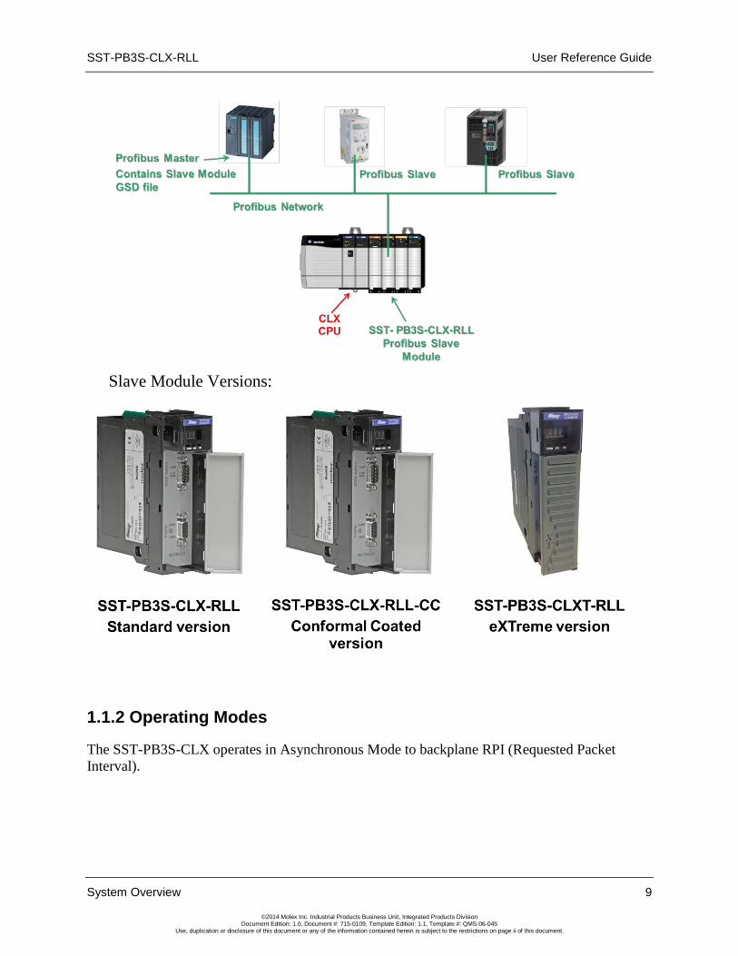
The SST-PB3S-CLX-RLL is a PROFIBUS slave-only interface for the 1756 (ControlLogix) backplane system. It enables communication between a CLX processor and Profibus slave device on a PROFIBUS network. The module:
• Supports standard ControlLogix or ControlLogix XT platforms
• Supports Rockwell’s RSLogix 5000 Add-on-Profile (AOP)
• Supports a range of 1-122 words of input data and 1-122 words of output data per slave module for a maximum of 244 words data exchange
• Can reside in any slot in the local or remote CLX chassis.
• Supports all standard PROFIBUS baud rates (9600, 19200, 45.45k, 93.75k, 187.5k, 500k, 1.5M, 3M, 6M, 12M)
• Acts as a DP-V0 slave interface
• Supports: Profibus repeaters in the network, data swapping, Auto-Run mode, legacy device ID, diagnostic LEDs and front-of-module scrolling LCD display
• Does not require ladder logic in the CLX to transfer data or configuration setup
• Direct module swap-out for quick module replacement
• Can be a drop-in replacement for Legacy SST-PFB-CLX module that is only configured as a slave (using Profibus ID 0x0876)
• Slave configuration via the ControlLogix configuration file
• Slave configuration via AOP interface which updates the configuration file automatically
SST-PB3S-CLX-RLL User Reference Guide
System Overview 9
©2014 Molex Inc. Industrial Products Business Unit, Integrated Products Division Document Edition: 1.0, Document #: 715-0109, Template Edition: 1.1, Template #: QMS-06-045
Use, duplication or disclosure of this document or any of the information contained herein is subject to the restrictions on page ii of this document.
Slave Module Versions:
1.1.2 Operating Modes
The SST-PB3S-CLX operates in Asynchronous Mode to backplane RPI (Requested Packet Interval).

User Reference Guide SST-PB3S-CLX-RLL
10 System Overview
©2014 Molex Inc. Industrial Products Business Unit, Integrated Products Division Document Edition: 1.0, Document #: 715-0109, Template Edition: 1.1, Template #: QMS-06-045
Use, duplication or disclosure of this document or any of the information contained herein is subject to the restrictions on page ii of this document.
SST-PB3S-CLX-RLL User Reference Guide
Hardware Overview 11
©2014 Molex Inc. Industrial Products Business Unit, Integrated Products Division Document Edition: 1.0, Document #: 715-0109, Template Edition: 1.1, Template #: QMS-06-045
Use, duplication or disclosure of this document or any of the information contained herein is subject to the restrictions on page ii of this document.
2 Hardware Overview
Chapter Sections:
• Hardware Features
User Reference Guide SST-PB3S-CLX-RLL
12 Hardware Overview
©2014 Molex Inc. Industrial Products Business Unit, Integrated Products Division Document Edition: 1.0, Document #: 715-0109, Template Edition: 1.1, Template #: QMS-06-045
Use, duplication or disclosure of this document or any of the information contained herein is subject to the restrictions on page ii of this document.
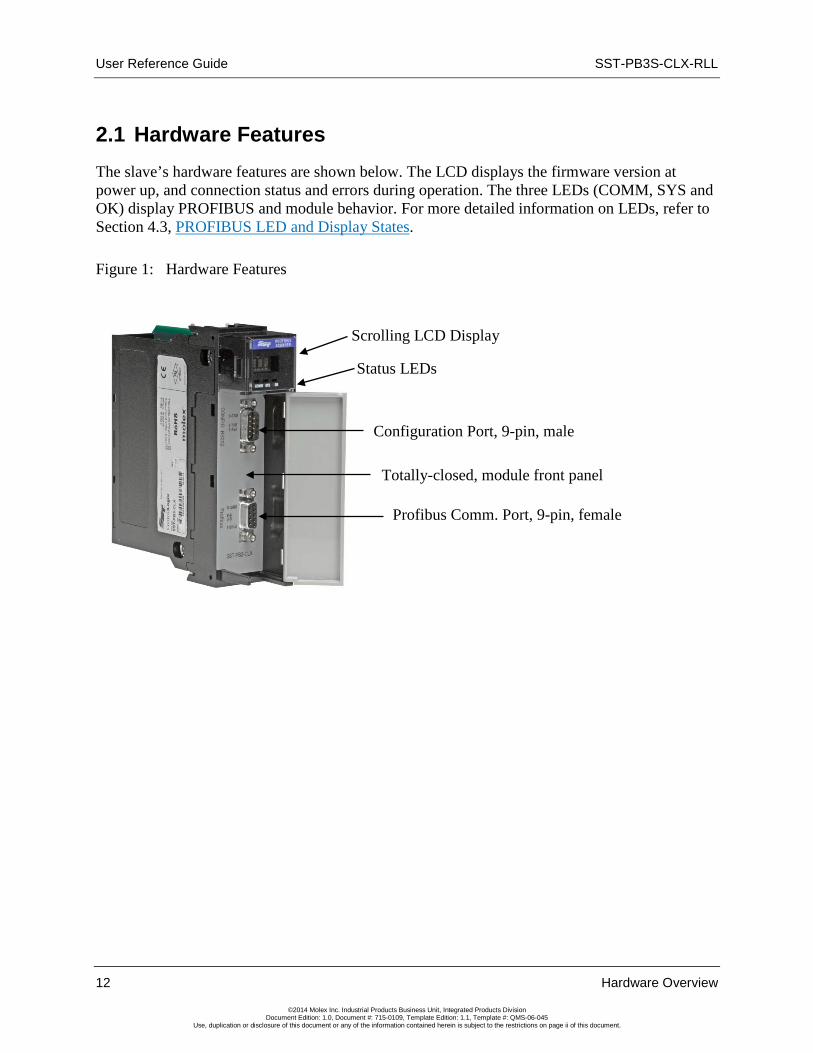
2.1 Hardware Features The slave’s hardware features are shown below. The LCD displays the firmware version at power up, and connection status and errors during operation. The three LEDs (COMM, SYS and OK) display PROFIBUS and module behavior. For more detailed information on LEDs, refer to Section 4.3, PROFIBUS LED and Display States.
Figure 1: Hardware Features
Status LEDs
Scrolling LCD Display
Configuration Port, 9-pin, male
Profibus Comm. Port, 9-pin, female
Totally-closed, module front panel
SST-PB3S-CLX-RLL User Reference Guide
Hardware Overview 13
©2014 Molex Inc. Industrial Products Business Unit, Integrated Products Division Document Edition: 1.0, Document #: 715-0109, Template Edition: 1.1, Template #: QMS-06-045
Use, duplication or disclosure of this document or any of the information contained herein is subject to the restrictions on page ii of this document.
Table 1: Description of Features
Feature Description
Status LEDs Display the communication and system status
Front panel Identifies the device, ports and protects internal electronic components from dust, contaminants and possible damage
9-pin PROFIBUS Connector
For connection to the PROFIBUS network
Self-locking tabs Secure the slave in the chassis slot
Side label (nameplate) Provides module information
Display CLX Connection status faults, operation status
Configuration port For upgrading module firmware
2.1.1 Status LEDs There are three LEDs on the module, the COMM LED, SYS LED and the OK LED. For detailed information, refer to Section 4.3, PROFIBUS LED and Display States.
COMM LED
The COMM LED remains off while the slave is online and operating correctly. The only time this LED remains RED is when a fatal error occurs. The COMM and SYS LED will go red at the same time to indicate an unrecoverable fatal error.
SYS LED
The SYS LED indicates the communication status with the PROFIBUS Slave. When the SYS LED is solid red, the PROFIBUS Slave is no longer being scanned by a DP Master, and when it is solid green, the PROFIBUS Slave is successfully being scanned by a DP Master in Run mode. An amber SYS LED indicates that the PROFIBUS Slave is being successfully scanned by a DP Master that is in Clear mode.
OK LED
The OK LED indicates that initialization is complete and that the module is OK.
2.1.2 9-Pin PROFIBUS Connector
The 9-pin PROFIBUS Connector connects the slave to the PROFIBUS network.
2.1.3 Configuration Port
Use the configuration port to upgrade module’s firmware.
User Reference Guide SST-PB3S-CLX-RLL
14 Hardware Overview
©2014 Molex Inc. Industrial Products Business Unit, Integrated Products Division Document Edition: 1.0, Document #: 715-0109, Template Edition: 1.1, Template #: QMS-06-045
Use, duplication or disclosure of this document or any of the information contained herein is subject to the restrictions on page ii of this document.

SST-PB3S-CLX-RLL User Reference Guide
Quick Start 15
©2014 Molex Inc. Industrial Products Business Unit, Integrated Products Division Document Edition: 1.0, Document #: 715-0109, Template Edition: 1.1, Template #: QMS-06-045
Use, duplication or disclosure of this document or any of the information contained herein is subject to the restrictions on page ii of this document.
3 Quick Start
Chapter Sections:
• Purpose
• Equipment and Tools
• Package Contents
• Power Requirements
• Procedures

User Reference Guide SST-PB3S-CLX-RLL
16 Quick Start
©2014 Molex Inc. Industrial Products Business Unit, Integrated Products Division Document Edition: 1.0, Document #: 715-0109, Template Edition: 1.1, Template #: QMS-06-045
Use, duplication or disclosure of this document or any of the information contained herein is subject to the restrictions on page ii of this document.
3.1 Purpose Although this section does not include detailed information in its procedures, other chapters are referenced where more information is available. These procedures are written with the assumption that you have a basic understanding of process control and are fully able to interpret the ladder logic instructions that control the applications.
3.2 Equipment and Tools Have the following tools and equipment ready:
• Computer containing Rockwell Automation RS-Logix5000 or Studio 5000 software with Molex SST Add On Profiles
• Cable to connect computer to CLX system
• SST-PB3S-CLX-RLL slave module
• SST-PB3S-CLX-RLL slave GSD file (ssti0EC7.gse). This can be found on the Product CD at location CD:\Product Files\SST-PB3S-CLX-RLL\GSD
• SST-PB3S-CLX-RLL ladder samples (sstpb3sclx_generic_profile_sample.acd (For Generic Profile), sstpb3sclx_AOP_sample.acd (For Add-On-Profile). These samples can be accessed from selecting the SST-PB3S-CLX-RLL product from product CD and moved to PC.
• PROFIBUS cable to connect the slave module to the PROFIBUS network
3.3 Package Contents Unpack the SST-PB3S-CLX-RLL slave module. Make sure that the contents include:
• PROFIBUS slave
• PDF version of this manual included on the CD
• CD with files for Windows XP/Server 2003 32-bit installation and Windows Vista/Server 2008/Windows 7/Windows 8 32-bit and 64-bit installations

SST-PB3S-CLX-RLL User Reference Guide
Quick Start 17
©2014 Molex Inc. Industrial Products Business Unit, Integrated Products Division Document Edition: 1.0, Document #: 715-0109, Template Edition: 1.1, Template #: QMS-06-045
Use, duplication or disclosure of this document or any of the information contained herein is subject to the restrictions on page ii of this document.
3.4 Power Requirements Review your system’s power requirements to see that your chassis supports placement of the SST-PB3S-CLX-RLL module.
Note The module consumes 850 mA @ 5VDC, 1.75 mA @ 24VDC.
For modular systems, calculate the total load on the system power supply using the procedure described in the CLX 5000 Modular Style Installation & Operation Manual, Allen-Bradley Publication 1747-6.2
3.5 Procedures The setup of the SST-PB3S-CLX-RLL slave is divided into two parts:
• Setting up the slave module
• Getting the slave running
3.5.1 Setting up the Slave Module
The following steps describe the SST-PB3S-CLX-RLL setup procedure:
Warning If installing the module while the chassis is powered up, make sure the environment is free of explosive or hazardous dusts or gases. If there is a possibility of gases present, remove the hazardous dusts or gases, and power down the chassis before installing the module. Serious injury or damage to equipment may result if this warning is not followed.
1. Insert the slave module into your 1756 CLX chassis.
2. Connect the slave to the PROFIBUS network using the appropriate cabling and termination. Refer to Section 4.2, PROFIBUS Wiring, for more detailed information.
3. Apply power to the CLX provided it is safe to do so.
4. Put the CLX PLC in Program mode. See your programming software manuals for details.
User Reference Guide SST-PB3S-CLX-RLL
18 Quick Start
©2014 Molex Inc. Industrial Products Business Unit, Integrated Products Division Document Edition: 1.0, Document #: 715-0109, Template Edition: 1.1, Template #: QMS-06-045
Use, duplication or disclosure of this document or any of the information contained herein is subject to the restrictions on page ii of this document.
3.5.2 Getting the Slave Module Running
The following steps describe how to set up the SST-PB3S-CLX-RLL:
1. Launch RSLogix5000 or Studio 5000 software.
2. Select I/O Configuration folder, select New Module, select Molex Incorporated in Module Type Vendor Filters, select SST-PB3-CLX-RLL, and select Create button.
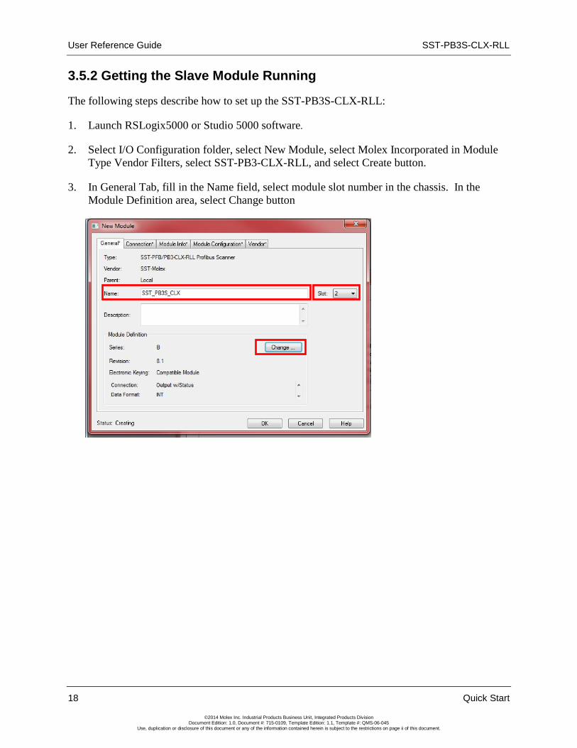
3. In General Tab, fill in the Name field, select module slot number in the chassis. In the Module Definition area, select Change button
SST-PB3S-CLX-RLL User Reference Guide
Quick Start 19
©2014 Molex Inc. Industrial Products Business Unit, Integrated Products Division Document Edition: 1.0, Document #: 715-0109, Template Edition: 1.1, Template #: QMS-06-045
Use, duplication or disclosure of this document or any of the information contained herein is subject to the restrictions on page ii of this document.
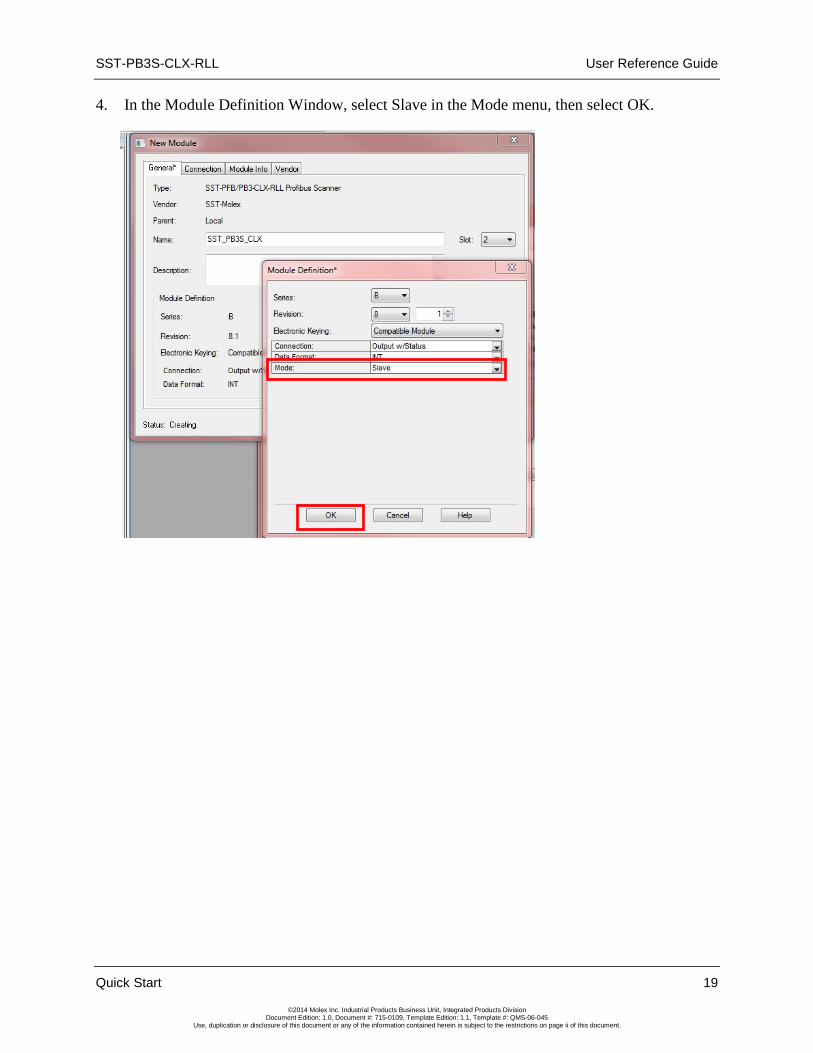
4. In the Module Definition Window, select Slave in the Mode menu, then select OK.
User Reference Guide SST-PB3S-CLX-RLL
20 Quick Start
©2014 Molex Inc. Industrial Products Business Unit, Integrated Products Division Document Edition: 1.0, Document #: 715-0109, Template Edition: 1.1, Template #: QMS-06-045
Use, duplication or disclosure of this document or any of the information contained herein is subject to the restrictions on page ii of this document.
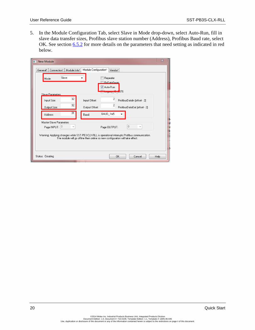
5. In the Module Configuration Tab, select Slave in Mode drop-down, select Auto-Run, fill in slave data transfer sizes, Profibus slave station number (Address), Profibus Baud rate, select OK. See section 6.5.2 for more details on the parameters that need setting as indicated in red below.

SST-PB3S-CLX-RLL User Reference Guide
Installing the SST-PB3S-CLX-RLL Slave 21
©2014 Molex Inc. Industrial Products Business Unit, Integrated Products Division Document Edition: 1.0, Document #: 715-0109, Template Edition: 1.1, Template #: QMS-06-045
Use, duplication or disclosure of this document or any of the information contained herein is subject to the restrictions on page ii of this document.
4 Installing the SST-PB3S-CLX-RLL Slave
Chapter Sections:
• Installing the Slave Module
• PROFIBUS Wiring
• PROFIBUS LED and Display States
• LED and Display combinations
User Reference Guide SST-PB3S-CLX-RLL
22 Installing the SST-PB3S-CLX-RLL Slave
©2014 Molex Inc. Industrial Products Business Unit, Integrated Products Division Document Edition: 1.0, Document #: 715-0109, Template Edition: 1.1, Template #: QMS-06-045
Use, duplication or disclosure of this document or any of the information contained herein is subject to the restrictions on page ii of this document.
4.1 Installing the Slave Module
4.1.1 Installation Procedure
The following procedure describes how to install the slave module:
Warning If installing the module while the chassis is powered up, make sure the environment is free of explosive or hazardous dusts or gases. If there is a possibility of gases present, remove the hazardous dusts or gases, and power down the chassis before installing the module. Serious injury or damage to equipment may result if this warning is not followed.
1. You can, but do not necessarily need to disconnect the power, as the slave supports insertion under power. Read and follow the Warning described above.
2. Using the chassis card guides, align the full-sized circuit board.
3. Slide the module into the chassis until the top and bottom latches catch.
4. Attach the PROFIBUS cable.
5. Turn on connector termination as required.
6. Route the cable down and away from the slave.
4.1.2 Removal Procedure
The following procedure describes how to uninstall the slave module:
Warning If removing the module while the chassis is powered up, make sure the environment is free of explosive or hazardous dusts or gases. If there is a possibility of gases present, remove the hazardous dusts or gases, and power down the chassis before removing the module. Serious injury or damage to equipment may result if this warning is not followed.
1. You can, but do not necessarily need to disconnect the power, as the slave supports removal under power. Read and follow the Warning described above.
2. Remove all cabling from the slave.
3. Press releases at the top and bottom of the module and slide the module out of the slot.
SST-PB3S-CLX-RLL User Reference Guide
Installing the SST-PB3S-CLX-RLL Slave 23
©2014 Molex Inc. Industrial Products Business Unit, Integrated Products Division Document Edition: 1.0, Document #: 715-0109, Template Edition: 1.1, Template #: QMS-06-045
Use, duplication or disclosure of this document or any of the information contained herein is subject to the restrictions on page ii of this document.
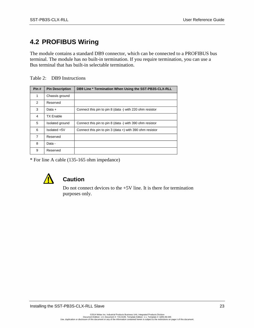
4.2 PROFIBUS Wiring The module contains a standard DB9 connector, which can be connected to a PROFIBUS bus terminal. The module has no built-in termination. If you require termination, you can use a Bus terminal that has built-in selectable termination.
Table 2: DB9 Instructions
Pin # Pin Description DB9 Line * Termination When Using the SST-PB3S-CLX-RLL
1 Chassis ground
2 Reserved
3 Data + Connect this pin to pin 8 (data -) with 220 ohm resistor
4 TX Enable
5 Isolated ground Connect this pin to pin 8 (data -) with 390 ohm resistor
6 Isolated +5V Connect this pin to pin 3 (data +) with 390 ohm resistor
7 Reserved
8 Data -
9 Reserved
* For line A cable (135-165 ohm impedance)
Caution Do not connect devices to the +5V line. It is there for termination purposes only.

User Reference Guide SST-PB3S-CLX-RLL
24 Installing the SST-PB3S-CLX-RLL Slave
©2014 Molex Inc. Industrial Products Business Unit, Integrated Products Division Document Edition: 1.0, Document #: 715-0109, Template Edition: 1.1, Template #: QMS-06-045
Use, duplication or disclosure of this document or any of the information contained herein is subject to the restrictions on page ii of this document.
4.2.1 Selecting the Proper Line Type
Use this table to determine which line type best suits your system requirements.
Table 3: Line Types
Baud Rate (Bits/s) Line A Distance (Max) Line B Distance (Max) Register Value
9k6, 19.2k, 45.45 k and 93.75k 1200 m** 1200 m** 0, 1, 11, 2
187.5k 1000 m** 600 m** 3
500k 400 m** 200 m** 4
1.5M 200 m** NA 6
3, 6 and 12M 100 m** NA 7, 8, 9
NA = Not Applicable *If using a combination of both line types, divide the lengths shown by two. **This is the sum of all bus segment and drop cable lengths.
Note The two physical ends of the PROFIBUS network should be terminated. There should be only two terminators on a network.

SST-PB3S-CLX-RLL User Reference Guide
Installing the SST-PB3S-CLX-RLL Slave 25
©2014 Molex Inc. Industrial Products Business Unit, Integrated Products Division Document Edition: 1.0, Document #: 715-0109, Template Edition: 1.1, Template #: QMS-06-045
Use, duplication or disclosure of this document or any of the information contained herein is subject to the restrictions on page ii of this document.
4.2.2 PROFIBUS Connector
The card has one standard PROFIBUS DB9 female connector per channel. Pin numbers are identified in the following figure.
Figure 2: The PROFIBUS DB9 Female Connector
Note The recommended male connector is the Brad Harrison PA9D01-42 Diagnostic D-Sub Connector.
The recommended cable is a Belden3079A. Examples include:
• Brad Harrison 85-001 PVR2 conductor with shield, UL-listed PROFIBUS cable
• Bosch Comnet DP #913 548 Flexible PROFIBUS cable
• Bosch Comnet DP #917 201 Trailing PROFIBUS cable
• Bosch Comnet DP #917 202 Massive PROFIBUS cable
Note Allen Bradley blue hose, which has an impedance of 78 ohms, is not recommended.
User Reference Guide SST-PB3S-CLX-RLL
26 Installing the SST-PB3S-CLX-RLL Slave
©2014 Molex Inc. Industrial Products Business Unit, Integrated Products Division Document Edition: 1.0, Document #: 715-0109, Template Edition: 1.1, Template #: QMS-06-045
Use, duplication or disclosure of this document or any of the information contained herein is subject to the restrictions on page ii of this document.
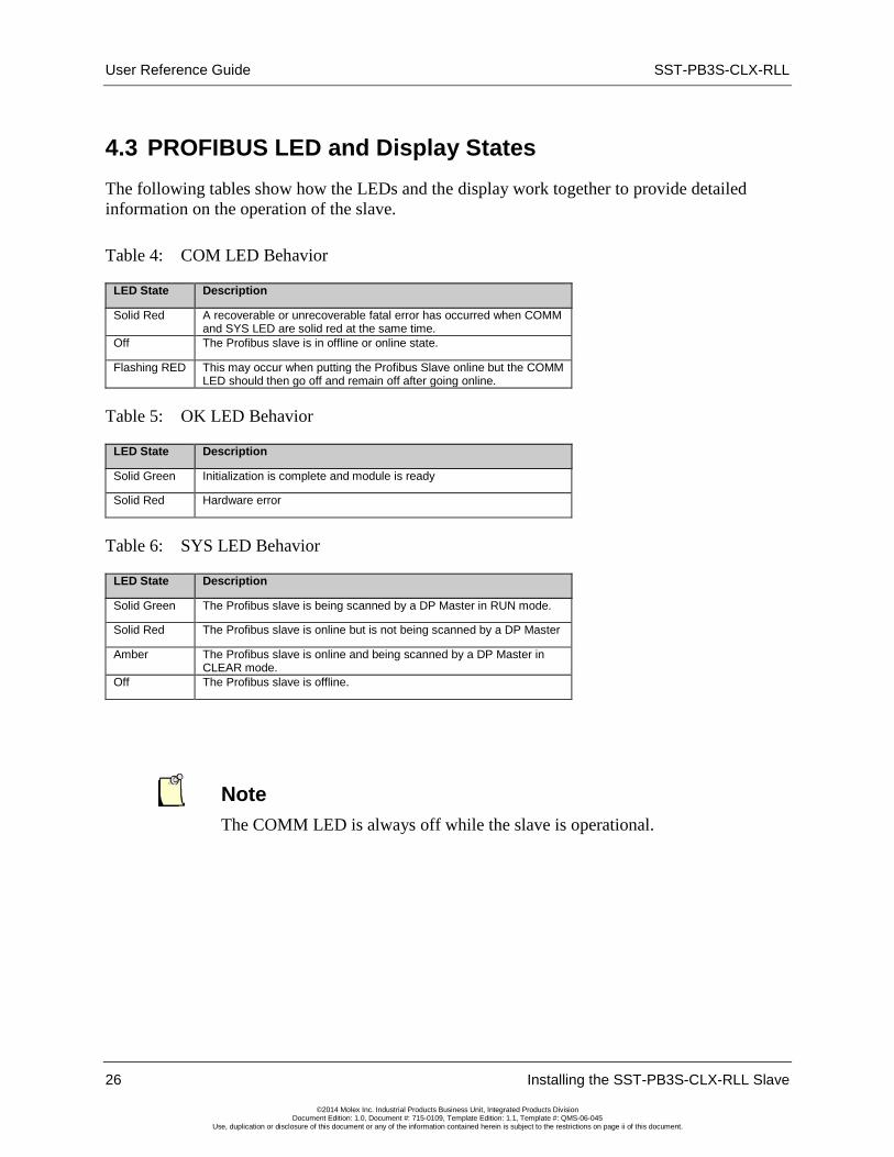
4.3 PROFIBUS LED and Display States The following tables show how the LEDs and the display work together to provide detailed information on the operation of the slave.
Table 4: COM LED Behavior
LED State Description
Solid Red A recoverable or unrecoverable fatal error has occurred when COMM and SYS LED are solid red at the same time.
Off The Profibus slave is in offline or online state.
Flashing RED This may occur when putting the Profibus Slave online but the COMM LED should then go off and remain off after going online.
Table 5: OK LED Behavior
LED State Description
Solid Green Initialization is complete and module is ready
Solid Red Hardware error
Table 6: SYS LED Behavior
LED State Description
Solid Green The Profibus slave is being scanned by a DP Master in RUN mode.
Solid Red The Profibus slave is online but is not being scanned by a DP Master
Amber The Profibus slave is online and being scanned by a DP Master in CLEAR mode.
Off The Profibus slave is offline.
Note The COMM LED is always off while the slave is operational.

SST-PB3S-CLX-RLL User Reference Guide
Installing the SST-PB3S-CLX-RLL Slave 27
©2014 Molex Inc. Industrial Products Business Unit, Integrated Products Division Document Edition: 1.0, Document #: 715-0109, Template Edition: 1.1, Template #: QMS-06-045
Use, duplication or disclosure of this document or any of the information contained herein is subject to the restrictions on page ii of this document.
4.4 LED and Display Combinations While a connection is open, COPN shows on the LCD Display. From left to right, the LEDs are COMM, SYS and OK. The COM LED may go RED when the slave is first put online but then it will remain off while the card is online.
Table 7: LED and Display Combinations
COPN State Description
OK LED green and SYS LED is amber.
Card is online and being scanned in CLEAR mode by DP Master and the connection is open.
OK LED is green and COMM and SYS are off.
Card is offline and the connection is open.
SYS and OK LEDs are green. COMM is off.
Card is online and being scanned in RUN mode by a DP Master and the connection is open
COMM is Off. SYS LED is red and OK LED is GREEN.
Card is online and is not being scanned by a DP Master.

User Reference Guide SST-PB3S-CLX-RLL
28 Installing the SST-PB3S-CLX-RLL Slave
©2014 Molex Inc. Industrial Products Business Unit, Integrated Products Division Document Edition: 1.0, Document #: 715-0109, Template Edition: 1.1, Template #: QMS-06-045
Use, duplication or disclosure of this document or any of the information contained herein is subject to the restrictions on page ii of this document.
4.5.1 Display Tables
The following table shows scrolling LCD display information and descriptions:
Table 8: SST-PB3S-CLX-RLL Display
Display Meaning/Description
Ver x.xx Power up message. This message appears briefly during power up. x.xx is the firmware version.
Invalid Serial Number The serial number has not yet been programmed on this module.
CLX INIT FALT 0xYY ControlLogix Initialization fault. The ControlLogix Backplane startup routines failed, with failure code YY (hex).
CONNCLSD There are no open ControlLogix Backplane connections.
NVLD XMIT SIZE Invalid transmit size. The size of the transmitted data for a new connection does not match that of an existing connection.
NVLD OUT CNPT Invalid output connection point.
NVLD RCV SIZE Invalid receive size. The size of the received data for the connection is invalid.
NVLD RCV BUFF Invalid receive buffer. Failed to allocate a receive buffer. This should never happen.
CONN BLKED Connections blocked (not allowed). The Connection Manager is in a Connections not allowed state. This should never happen.
DUPLCONN DTCT Duplicate connection detected. Connection is already open.
RSRC ERR1 INCM Resource error # 1 in Connection Manager: Out of memory. This should never happen.
NVLD FWD OPEN Invalid forward open. CM was unable to parse the Forward open. May be a key segment mismatch.
NVLD SRVC CODE Invalid service code. Service code in CLX Forward Open was invalid.
WDOG Watchdog timeout. The module watchdog has timed out.
OFPT Slave firmware operational fault.
Backplane OK SST-PB3S-CLX-RLL resides in the rack that is powered on but not configured in the CLX Controller.
Booting SST-PB3S-CLX-RLL is just powering up and initializing.
COPN Connection open.
MULT Multiple processors are attempting to connect to the slave.
IDMSM There is a Profibus Slave ID Mismatch. The DP Master is trying to configure module with wrong Slave ID
Note The default LCD display is COPN when the slave is working correctly.

SST-PB3S-CLX-RLL User Reference Guide
System Diagnostics 29
©2014 Molex Inc. Industrial Products Business Unit, Integrated Products Division Document Edition: 1.0, Document #: 715-0109, Template Edition: 1.1, Template #: QMS-06-045
Use, duplication or disclosure of this document or any of the information contained herein is subject to the restrictions on page ii of this document.
5 System Diagnostics
Chapter Sections:
• PB3S Status Register
• Slave Firmware Version
• Diagnostic Counters

User Reference Guide SST-PB3S-CLX-RLL
30 System Diagnostics
©2014 Molex Inc. Industrial Products Business Unit, Integrated Products Division Document Edition: 1.0, Document #: 715-0109, Template Edition: 1.1, Template #: QMS-06-045
Use, duplication or disclosure of this document or any of the information contained herein is subject to the restrictions on page ii of this document.
5.1 PB3S Status Register
Local:Slot:S.Data[0] , AOP Tag Local:Slot:S.PfbStatus
The first 16-bit INT in the Status area is the Card Status register. The following tables show possible status register values.
Table 9: PfbStatus
Status Name Meaning/Description Value
STS_NO_ERROR The SST-PB3S-CLX-RLL has no errors 0x0000
STS_BAD_BAUD The configured baud rate is not valid 0x0002
STS_BAD_STN_ADR The configured station address is not valid 0x0003
STS_BAD_HI_STN_ADR The configured Highest Station Address is not valid
0x0004
STS_CFG_INTERNAL_ERROR The SST-PB3S-CLX-RLL has encountered a fatal internal error
0x0080
STS_OUT_OF_APBS The SST-PB3S-CLX-RLL has run out of internal resources
0x0081
STS_HEAP_ALLOC_FAIL The SST-PB3S-CLX-RLL has run out of internal resources
0x0083
STS_SH_HEAP_ALLOC_FAIL The SST-PB3S-CLX-RLL has run out of internal resources
0x0084
If the status register contains STS_CFG_INTERNAL_ERROR (80h), there has been an internal error on the slave. Record the contents of the ErrInternal and errArg registers and contact Technical Support. ErrInternal is stored in the high byte of status area offset 24. ErrArg is stored in the low byte of status area offset 25.
If the status register contains STS_HEAP_ALLOC_FAIL (83h) or STS_SH_HEAP_ALLOC_ FAIL (84h), there has been an internal error in allocating memory. Contact Technical Support.
5.2 Slave Firmware Version The version number of the slave firmware is stored in status area offset 1. For example, if the Word corresponding to the value is 0800h, then the firmware is version 8.00.
SST-PB3S-CLX-RLL User Reference Guide
System Diagnostics 31
©2014 Molex Inc. Industrial Products Business Unit, Integrated Products Division Document Edition: 1.0, Document #: 715-0109, Template Edition: 1.1, Template #: QMS-06-045
Use, duplication or disclosure of this document or any of the information contained herein is subject to the restrictions on page ii of this document.
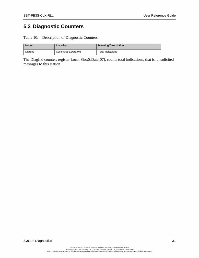
5.3 Diagnostic Counters
Table 10: Description of Diagnostic Counters
Name Location Meaning/Description
DiagInd Local:Slot:S.Data[07] Total indications
The DiagInd counter, register Local:Slot:S.Data[07], counts total indications, that is, unsolicited messages to this station

User Reference Guide SST-PB3S-CLX-RLL
32 System Diagnostics
©2014 Molex Inc. Industrial Products Business Unit, Integrated Products Division Document Edition: 1.0, Document #: 715-0109, Template Edition: 1.1, Template #: QMS-06-045
Use, duplication or disclosure of this document or any of the information contained herein is subject to the restrictions on page ii of this document.

SST-PB3S-CLX-RLL User Reference Guide
Slave Functionality 33
©2014 Molex Inc. Industrial Products Business Unit, Integrated Products Division Document Edition: 1.0, Document #: 715-0109, Template Edition: 1.1, Template #: QMS-06-045
Use, duplication or disclosure of this document or any of the information contained herein is subject to the restrictions on page ii of this document.
6 Slave Functionality
Chapter Sections:
• Slave I/O Interface
• Register Definitions and Layout
• I/O Table Additions/Modifications
• Config Table Additions
• Slave Configuration and Programming
User Reference Guide SST-PB3S-CLX-RLL
34 Slave Functionality
©2014 Molex Inc. Industrial Products Business Unit, Integrated Products Division Document Edition: 1.0, Document #: 715-0109, Template Edition: 1.1, Template #: QMS-06-045
Use, duplication or disclosure of this document or any of the information contained herein is subject to the restrictions on page ii of this document.
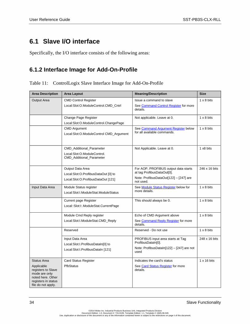
6.1 Slave I/O interface Specifically, the I/O interface consists of the following areas:
6.1.2 Interface Image for Add-On-Profile
Table 11: ControlLogix Slave Interface Image for Add-On-Profile
Area Description Area Layout Meaning/Description Size
Output Area CMD Control Register Local:Slot:O.ModuleControl.CMD_Cntrl
Issue a command to slave See Command Control Register for more details.
1 x 8 bits
Change Page Register Local:Slot:O.ModuleControl.ChangePage
Not applicable. Leave at 0.
1 x 8 bits
CMD Argument Local:Slot:O.ModuleControl CMD_Argument
See Command Argument Register below for all available commands.
1 x 8 bits
CMD_Additional_Parameter Local:Slot:O.ModuleControl. CMD_Additional_Parameter
Not Applicable. Leave at 0. 1 x8 bits
Output Data Area Local:Slot:O.ProfibusDataOut [0] to Local:Slot:O.ProfibusDataOut [121]
For AOP, PROFIBUS output data starts at tag ProfibusDataOut[0]. Note: ProfibusDataOut[122] – [247] are not used.
246 x 16 bits
Input Data Area
Module Status register Local:Slot:I.ModuleStat.ModuleStatus
See Module Status Register below for more details.
1 x 8 bits
Current page Register Local::Slot:I:.ModuleStat.CurrentPage
This should always be 0. 1 x 8 bits
Module Cmd Reply register Local:Slot:I.ModuleStat.CMD_Reply
Echo of CMD Argument above See Command Reply Register for more details.
1 x 8 bits
Reserved Reserved - Do not use 1 x 8 bits
Input Data Area Local:Slot:I.ProfibusDataIn[0] to Local:Slot:I.ProfibusDataIn [121]
PROFIBUS input area starts at Tag ProfibusDataIn[0]. Note: ProfibusDataIn[122] – [247] are not used
248 x 16 bits
Status Area Applicable registers to Slave mode are only noted here. Other registers in status file do not apply.
Card Status Register PfbStatus
Indicates the card’s status See Card Status Register for more details.
1 x 16 bits

SST-PB3S-CLX-RLL User Reference Guide
Slave Functionality 35
©2014 Molex Inc. Industrial Products Business Unit, Integrated Products Division Document Edition: 1.0, Document #: 715-0109, Template Edition: 1.1, Template #: QMS-06-045
Use, duplication or disclosure of this document or any of the information contained herein is subject to the restrictions on page ii of this document.
Area Description Area Layout Meaning/Description Size
Profibus Firmware Version PfbModVer
Indicates Profibus firmware version 1 x 16 bits
AOP Tags between PfbModVer and ReconfigStatus do not apply to this module
Reconfiguration Status ReconfigStatus
Status of Reconfig message that is sent when applying configuration change while a connection is open to module in RSLogix 5000.
1 x 8 Bits
AOP Tags between ReconfigStatus and DiagInd do not apply to this module
Diagnostic Indications DiagInd
Indicates module is getting updates from Profibus network
1 x 16 Bits
AOP Tags between DiagInd and SlvStatus do not apply to this module
SlvStatus Local slave status register See Slave Status below for more details
1 x 8 Bits
SlvError Local slave error register that contains error code. See Slave Error Codes below for more details.
1 x 8 Bits
Remaining AOP tags do not apply to this module
6.1.3 Interface Image for Generic Profile
Table 12: ControlLogix Slave Interface Image (for Generic Profile using INT Data type)
Area Description Area Layout Meaning/Description Size
Output Area CMD Control Register (low byte) Local:Slot:O.Data[0]
Issue a command to slave See Command Control Register for more details.
16 bits
CMD Argument (low byte) Local:Slot:O.Data[1]
See Command Argument Register below for all available commands.
16 bits
Output Data Area Local:Slot:O.Data[2] to Local:Slot:O.Data[123]
PROFIBUS output data starts at word offset 2.
122 x 16 bits
Input Data Area
Module Status register (bits 0 -7) Local:Slot:I.Data[0]
See Module Status Register below for more details.
16 bits
Module Cmd Reply register Local:Slot:I.Data[1]
Echo of CMD Argument above See Command Reply Register for more details.
16 bits
Input Data Area Local:Slot:I.ProfibusDataIn[2] to Local:Slot:I.ProfibusDataIn [123]
PROFIBUS input area starts at word offset 2.
122 x 16 bits
Status Area
Card Status Register (Local:Slot:S.Data[0])
Indicates the card’s status See Card Status Register for more details
1 x 16 bits
Profibus Module Version (Local:Slot:S.Data[1])
Indicates Profibus firmware version 1 x 16 bits
Diagnostic Indications (Local:Slot:S.Data [07]
Indicates module is getting updates from Profibus network
1 x 16 Bits

User Reference Guide SST-PB3S-CLX-RLL
36 Slave Functionality
©2014 Molex Inc. Industrial Products Business Unit, Integrated Products Division Document Edition: 1.0, Document #: 715-0109, Template Edition: 1.1, Template #: QMS-06-045
Use, duplication or disclosure of this document or any of the information contained herein is subject to the restrictions on page ii of this document.
Area Description Area Layout Meaning/Description Size
Reconfiguration Status (Local:Slot:S.Data[4].8-15)
Status of Reconfig message that is sent when applying configuration change while a connection is open to module in RSLogix 5000.
1 x 8 Bits
Slave status (Local: Slot:S.Data [44].00-07 Local slave status register See Slave Status below for more details
1 x 8 Bits
Slave Error (Local: Slot:S.Data [44].08-15) Local slave error register that contains error code. See Slave Error Codes below for more details.
1 x 8 Bits
Table 13: CMD Control Register (Local:Slot:O.Data[0], AOP Tag Local:Slot:O.ModuleControl.CMD_Control)
Value, Hex Meaning/Description
00 No Command in CMD Argument register
01 Issue the command that is in the CMD Argument register
Table 14: CMD Argument Register (Local:Slot:O.Data[1].0 – 7, AOP Tag Local:Slot:O.ModuleControl.CMD_Argument )
Value, Hex Meaning/Description
00 No Command
03 PFB_CLR_ERR_CNT- Clear counters in Status area
04 PFB_ONLINE- Put slave online with PROFIBUS bus
07 PFB_OFFLINE - Put slave offline with the PROFIBUS bus
Table 15: Module Status Register (Local:Slot:I.Data[0].0 -7, AOP Tag Local:Slot:I.ModuleStat.ModuleStatus)
Value, Hex Meaning/Description
E0 Slave is not online with PROFIBUS bus. Issue the PFB_START_BUS command to put it online.
E1 Slave is online with the PROFIBUS bus.
FF The CLX processor has lost its connection to the slave module. All data in the Input and Status tables should be considered invalid.
SST-PB3S-CLX-RLL User Reference Guide
Slave Functionality 37
©2014 Molex Inc. Industrial Products Business Unit, Integrated Products Division Document Edition: 1.0, Document #: 715-0109, Template Edition: 1.1, Template #: QMS-06-045
Use, duplication or disclosure of this document or any of the information contained herein is subject to the restrictions on page ii of this document.
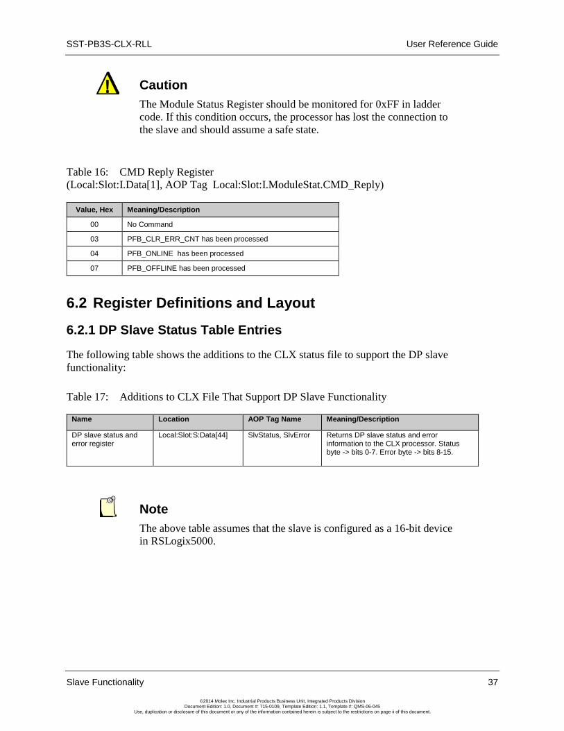
Caution The Module Status Register should be monitored for 0xFF in ladder code. If this condition occurs, the processor has lost the connection to the slave and should assume a safe state.
Table 16: CMD Reply Register (Local:Slot:I.Data[1], AOP Tag Local:Slot:I.ModuleStat.CMD_Reply)
Value, Hex Meaning/Description
00 No Command
03 PFB_CLR_ERR_CNT has been processed
04 PFB_ONLINE has been processed
07 PFB_OFFLINE has been processed
6.2 Register Definitions and Layout
6.2.1 DP Slave Status Table Entries
The following table shows the additions to the CLX status file to support the DP slave functionality:
Table 17: Additions to CLX File That Support DP Slave Functionality
Name Location AOP Tag Name Meaning/Description
DP slave status and error register
Local:Slot:S:Data[44] SlvStatus, SlvError Returns DP slave status and error information to the CLX processor. Status byte -> bits 0-7. Error byte -> bits 8-15.
Note The above table assumes that the slave is configured as a 16-bit device in RSLogix5000.

User Reference Guide SST-PB3S-CLX-RLL
38 Slave Functionality
©2014 Molex Inc. Industrial Products Business Unit, Integrated Products Division Document Edition: 1.0, Document #: 715-0109, Template Edition: 1.1, Template #: QMS-06-045
Use, duplication or disclosure of this document or any of the information contained herein is subject to the restrictions on page ii of this document.
Table 18: DP Slave Status and Error Register
Name Location AOP Tag Name Meaning/Description
DP slave status bit 0 - 5 Local:Slot:S:Data[44].0 - 5 None Reserved for future use
DP slave status SLV_STS_RUN_MODE bit
Local:Slot:S:Data[44].6 SlvStsRunMode Set to True if the slave is being scanned by a remote master in "RUN" mode.
DP slave status SLV_STS_OK bit
Local:Slot:S:Data[44].7 SlvStatusOk Set to True if the current slave status is OK. This means parameterization was successful and the slave watchdog has not timed out.
DP slave error byte Local:Slot:S:Data[44].8-15 SlvError The slave sets the error byte to report various error conditions. If there are multiple errors, the register contains the value of the last error encountered.
Table 19: DP Slave Error Byte (Local:Slot:S:Data[44].8-15, AOP tag Local:Slot.S.SlvError)
Value Error Meaning/Description
01h SLV_ERR_ID_MISM Slave ID does not match the slave ID configured in the master. If there is a mismatch, the slave won't communicate with the master.
02h SLV_ERR_READY_TIME_MISM Ready time for the card is different from the value configured in the master. The card can communicate as a slave even if the times are different, but you may experience network errors.
03h SLV_ERR_UNSUP_REQ Master has requested Sync or Freeze during parameterization, which the card does not support.
04h SLV_ERR_RX_LEN_MISM Data received from the master has a length different from the length configured on the card. If there is a receive length mismatch, the card won't communicate as a slave.
05h SLV_ERR_TX_LEN_MISM Master has requested data from the slave with a length different from the length configured for the slave. If there is a transmit length mismatch, the card won't communicate as a slave.
06h SLV_ERR_WD_FACT_INV One of the two slave watchdog factors is zero, which is not allowed.
07h SLV_ERR_TIME_OUT Slave's watchdog timed out. The slave goes offline and must be reinitialized by the master.
08h SLV_ERR_WARN_WD_DIS Master has disabled the slave watchdog.
Note All errors (except SLV_ERR_TIME_OUT) occur when the slave is being parameterized by the master.

SST-PB3S-CLX-RLL User Reference Guide
Slave Functionality 39
©2014 Molex Inc. Industrial Products Business Unit, Integrated Products Division Document Edition: 1.0, Document #: 715-0109, Template Edition: 1.1, Template #: QMS-06-045
Use, duplication or disclosure of this document or any of the information contained herein is subject to the restrictions on page ii of this document.
6.3 I/O Table Additions/Modifications
Note If you are using AOP to configure module as a slave, you do not have to edit the CLX configuration table manually. Editing the CLX configuration table is only required when using Generic 1756 Module Profile.
Received data is data received from the remote master. This data is mapped into the CLX input table starting at word offset 2. Transmit data is data that the slave module sends to the remote master. This data is mapped into the CLX output table starting at word offset 2.
6.4 Config Table Additions The CLX config table will be used to configure the slave functionality. If using Rockwell’s AOP to do the configuration, see section 6.5.2, Configuring the CLX Slave in RSLogix 5000 using Add-on-Profile (AOP).
The slave config file entries start at 10H (16D).
Note The CLX config file is always configured as byte locations. The CLX config file must be set to at least 24 bytes in size for Slave-only Mode.

User Reference Guide SST-PB3S-CLX-RLL
40 Slave Functionality
©2014 Molex Inc. Industrial Products Business Unit, Integrated Products Division Document Edition: 1.0, Document #: 715-0109, Template Edition: 1.1, Template #: QMS-06-045
Use, duplication or disclosure of this document or any of the information contained herein is subject to the restrictions on page ii of this document.
The following table shows the additions to the CLX config table that support the DP slave functionality:
Table 20: Additions to CLX Config Table Supporting DP Slave Functionality
Name Location Meaning/Description
AUTORUN Local:Slot:C:Data[1] If 2, the module comes online automatically after powerup and enters the mode that the CLX processors is in (RUN or PROG)
ScannerConfig Local:Slot:C:Data[16] This register configures enables the slave mode. See the ScannerConfig Register table (follows this table).
SlvRxLen Local:Slot:C:Data[17] The length of slave receive data (in words)
SlvTxLen Local:Slot:C:Data[18] The length of slave transmit data (in words)
SlvRxOffset Local:Slot:C:Data[19] If 0, the DP slave Rx data will be mapped into the CLX Input file at word offset 2.If set to a non-zero value, it specifies the word offset into the CLX Input file where the slave Rx data should be mapped.
SlvTxOffset Local:Slot:C:Data[20] If 0, the DP slave Tx data will be mapped into the CLX Output file at word offset 2. If set to a non-zero value, it specifies the word offset into the CLX Output file where the slave Tx data should be mapped.
LocStn Local:Slot:C:Data[21] "LocStn" defines the Slave’s local station number. The valid range is 1-125.
Baud Local:Slot:C:Data[22] "Baud" defines the slave’s baud rate. The following table defines the valid PFB network rates and the corresponding value that is written into the Baud register. BAUD Rate Register Value BAUD_9k6 0 BAUD_19k2 1 BAUD_93k75 2 BAUD_187k5 3 BAUD_500k 4 BAUD_1m5 6 BAUD_3m 7 BAUD_6m 8 BAUD_12m 9 BAUD_45k45 11
Reptr Local:Slot:C:Data[23] This option does not apply to the slave only module and can be left at 0.
Table 21: AUTORUN / LEGACY_ID_0876 Register (Local:Slot:C:Data[1].1)
Name Location Meaning/Description
LEGACY_ID_0876 Local:Slot:C:Data[1].0 If set, Profibus ID 0x0876 will be used instead of 0x0EC7 for backward compatibility.
AUTORUN Local:Slot:C:Data[1].1 If set, AUTORUN is enabled. The Slave will come online automatically after powerup.

SST-PB3S-CLX-RLL User Reference Guide
Slave Functionality 41
©2014 Molex Inc. Industrial Products Business Unit, Integrated Products Division Document Edition: 1.0, Document #: 715-0109, Template Edition: 1.1, Template #: QMS-06-045
Use, duplication or disclosure of this document or any of the information contained herein is subject to the restrictions on page ii of this document.
Table 22: ScannerConfig Register (Local:Slot:C:Data[16])
Name Location Meaning/Description
SlvEna Local:Slot:C:Data[16].0 Has to be set to 1.The DP slave functionality is enabled
MasDisAbl Local:Slot:C:Data[16].1 Has to be set to 1 along with SlvEna bit being set to 1.
Rx Data Swap Local:Slot:C:Data[16].2 If Set, Slave Rx Data (from Master) will get swapped prior to copying to ControlLogix input table
Reserved Local:Slot:C:Data[16].3-7
Reserved
6.5 Slave Configuration and Programming
The CLX slave accepts the ControlLogix configuration only once after a connection is made to module. This means if you change the ControlLogix configuration file settings (Station number, baud rate and so on) in your RSLogix 5000 Program and download it to the ControlLogix PLC while the CLX slave is online, the new settings will not take effect. The recommended configuration method is to use AOP (Add-On-Profile). AOP allows quick reconfiguration of CLX slave while PLC is in RUN mode.
There are three ways to have the new configuration settings accepted:
1. Cycle power on the module before new configuration settings are accepted. This can be done be done by removing and reinserting module into rack while rack is powered. This method can be used if other modules in rack need to remain powered on.
2. If using AOP and while online with PLC in RUN mode with AUTORUN enabled for the CLX slave, the apply button can be clicked on after making changes in the Module configuration window. This will force the module to go offline and back online to use the new configuration settings.

User Reference Guide SST-PB3S-CLX-RLL
42 Slave Functionality
©2014 Molex Inc. Industrial Products Business Unit, Integrated Products Division Document Edition: 1.0, Document #: 715-0109, Template Edition: 1.1, Template #: QMS-06-045
Use, duplication or disclosure of this document or any of the information contained herein is subject to the restrictions on page ii of this document.
3. If using Generic profile (1756-Module) and while online with PLC in RUN mode do the
following steps: a. Change the slave parameters in the configuration assembly (Local:Slot:C.Data[0 –
23]). These changes should be saved in the offline project. Resave the project to upload tag values or go offline and make the same changes.
b. While online, inhibit the sample program for our module so that the code does not try to put our module back online after its taken offline.
c. Write the offline command (0x07) to module by writing 0x07 to Local:Slot:O:2.Data[1].
d. Set Local:Slot:O.Data[0] to 0x01 to trigger the command . e. Wait for the Module status register (Local:Slot:I.Data[0] to go to 0x00E0 (225 dec). f. Clear registers Local:Slot:O:2.Data[0] and Local:Slot:O:2.Data[1]. to 0. g. Close and reopen the connection to module by: i. Double clicking on our module in I/O configuration tree. ii. Selecting Connection tab. iii. Check “Inhibit Module”. iv. Click on Apply. v. Uncheck “Inhibit Module”. vi. Click on Apply.
6.5.1 Configuring the CLX Slave in RSLogix 5000 using Generic Profile
When configuring the CLX slave in RSLogix 5000, you must set up the following connection parameters:
1. Navigate to the I/O Configuration.
2. Right-Click on I/O Configuration and select New Module…
3. Click on By Category and select 1756-MODULE and click OK.
4. The New Module Properties dialog box appears similar to below allowing you to set connection parameters.
5. The Assembly Instance for the configuration must be set to 3 and Size to 24 (by default, the size is Zero). All other assembly instances and sizes are to be set as in the screenshot below. The generated tables for I/O, status and configuration are located under Controller tags and will appear as in screenshot below under the Module properties dialog box.

SST-PB3S-CLX-RLL User Reference Guide
Slave Functionality 43
©2014 Molex Inc. Industrial Products Business Unit, Integrated Products Division Document Edition: 1.0, Document #: 715-0109, Template Edition: 1.1, Template #: QMS-06-045
Use, duplication or disclosure of this document or any of the information contained herein is subject to the restrictions on page ii of this document.
6. Configure the RPI for the module by clicking on the Connection tab. The lowest supported RPI is 3ms.

User Reference Guide SST-PB3S-CLX-RLL
44 Slave Functionality
©2014 Molex Inc. Industrial Products Business Unit, Integrated Products Division Document Edition: 1.0, Document #: 715-0109, Template Edition: 1.1, Template #: QMS-06-045
Use, duplication or disclosure of this document or any of the information contained herein is subject to the restrictions on page ii of this document.
7. Click OK button.
8. See section 6.4 Config table Additions on setting the slave parameters in Configuration assembly (similar to Local:8:C as in above screenshot).

SST-PB3S-CLX-RLL User Reference Guide
Slave Functionality 45
©2014 Molex Inc. Industrial Products Business Unit, Integrated Products Division Document Edition: 1.0, Document #: 715-0109, Template Edition: 1.1, Template #: QMS-06-045
Use, duplication or disclosure of this document or any of the information contained herein is subject to the restrictions on page ii of this document.
6.5.2 Configuring the CLX Slave in RSLogix 5000 using Add-on-Profile (AOP)
With AOP, the configuration file is automatically updated and adjusted to the correct length to configure the module successfully. Follow the steps below to configure module as DP Slave.
1. See the quick start section 3.52 on the initial steps on getting the module added to the I/O
configuration in your RSLogix 5000 project and ready to configure.
2. To configure the module as Slave only, Click on the Module Configuration tab and configure the following parameters:
Mode: Select Slave.
Repeater: This option does not apply and can be left unchecked.
RxDataSwap: Set this if you want to swap the data coming from the master (Slave Rx data).
Auto-Run: Enable Auto-Run if you want the SST-PB3S-CLX-RLL to come online automatically and enter the mode the CLX CPU is in. If enabling Auto-Run and the SST-

User Reference Guide SST-PB3S-CLX-RLL
46 Slave Functionality
©2014 Molex Inc. Industrial Products Business Unit, Integrated Products Division Document Edition: 1.0, Document #: 715-0109, Template Edition: 1.1, Template #: QMS-06-045
Use, duplication or disclosure of this document or any of the information contained herein is subject to the restrictions on page ii of this document.
PB3S-CLX-RLL is currently offline, the SST-PB3S-CLX-RLL will still remain offline after being reconfigured. In order for the Auto-Run to take effect, the SST-PB3S-CLX-RLL must be reset. This can be done by sending a RESET message to the module by going to the Module Info tab and clicking on module Reset button and then selecting OK to warning message.
Legacy_ID_0876: Enable this option if you want the module to use legacy Profibus ID 0x0876 instead of 0xOEC7 when it’s operating in Slave mode. You must use the correct slave GSD file that goes with this slave ID. Use slave GSD file ssti0876.gse for Profibus ID 0x0876 and slave GSD file ssti0ec7.gse for Profibus ID 0x0EC7.
Slave Parameters
Input Size: This is the length of slave receive data in Words. Valid input size is 1- 122.
Output Size: This is the length of slave transmit data in Words. Valid output size is 1- 122.
Input Offset: Specifies the word offset into the CLX input file where the slave Rx data should be mapped. Leave this offset at the default value 2. By default, the input data begins at tag Local:Slot.ProfibusDataIn[0].
Output Offset: Specifies the word offset into the CLX output file where the slave Tx data should be mapped. Leave this offset at the default value 2. By default, the output begins at tag Local:Slot.ProfibusDataOut[0].
Address: – This is the local station number configured for the slave. The valid range is 1- 125.
Baud: This is the Baud rate and can be set to any one of these baud rates (9K6, 19K2, 93K75, 187K5, 500K, 1M5, 3M, 6M, 12M, 45k45).
AOP allows you to make modifications to you configuration and apply them while you have an open connection to module.
Warning Be aware that applying changes while the SST-PB3S-CLX-RLL is operational will interrupt Profibus communication. The card will go offline and online so the new configuration will take effect.
If you apply changes with AutoRun disabled, the SST-PB3S-CLX-RLL will stay offline until the ladder code issues the online command. If the CLX CPU is in PROG mode and AutoRun is enabled, the module will come back online. To see if applying the new configuration was successful, check the ReconfigStatus register in the module’s status file.

SST-PB3S-CLX-RLL User Reference Guide
Slave Functionality 47
©2014 Molex Inc. Industrial Products Business Unit, Integrated Products Division Document Edition: 1.0, Document #: 715-0109, Template Edition: 1.1, Template #: QMS-06-045
Use, duplication or disclosure of this document or any of the information contained herein is subject to the restrictions on page ii of this document.
3. Click on Connection tab and configure the RPI. The lowest supported RPI is 3ms.
4. Click on OK. The slave is now configured.
User Reference Guide SST-PB3S-CLX-RLL
48 Slave Functionality
©2014 Molex Inc. Industrial Products Business Unit, Integrated Products Division Document Edition: 1.0, Document #: 715-0109, Template Edition: 1.1, Template #: QMS-06-045
Use, duplication or disclosure of this document or any of the information contained herein is subject to the restrictions on page ii of this document.
SST-PB3S-CLX-RLL User Reference Guide
Technical Specifications 49
©2014 Molex Inc. Industrial Products Business Unit, Integrated Products Division Document Edition: 1.0, Document #: 715-0109, Template Edition: 1.1, Template #: QMS-06-045
Use, duplication or disclosure of this document or any of the information contained herein is subject to the restrictions on page ii of this document.
A Technical Specifications
Appendix Sections:
• Technical Specifications
User Reference Guide SST-PB3S-CLX-RLL
50 Technical Specifications
©2014 Molex Inc. Industrial Products Business Unit, Integrated Products Division Document Edition: 1.0, Document #: 715-0109, Template Edition: 1.1, Template #: QMS-06-045
Use, duplication or disclosure of this document or any of the information contained herein is subject to the restrictions on page ii of this document.
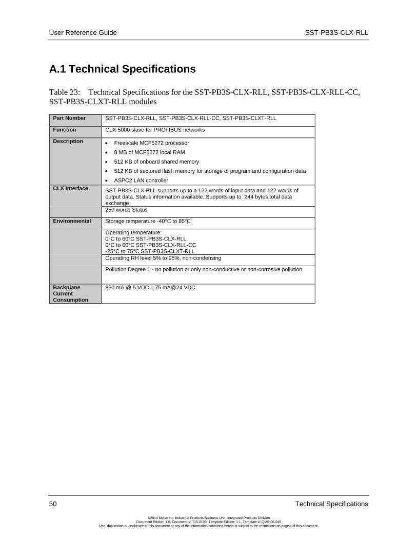
A.1 Technical Specifications
Table 23: Technical Specifications for the SST-PB3S-CLX-RLL, SST-PB3S-CLX-RLL-CC, SST-PB3S-CLXT-RLL modules
Part Number SST-PB3S-CLX-RLL, SST-PB3S-CLX-RLL-CC, SST-PB3S-CLXT-RLL
Function CLX-5000 slave for PROFIBUS networks
Description • Freescale MCF5272 processor
• 8 MB of MCF5272 local RAM
• 512 KB of onboard shared memory
• 512 KB of sectored flash memory for storage of program and configuration data
• ASPC2 LAN controller CLX Interface SST-PB3S-CLX-RLL supports up to a 122 words of input data and 122 words of
output data. Status information available..Supports up to 244 bytes total data exchange
250 words Status
Environmental Storage temperature -40°C to 85°C
Operating temperature: 0°C to 60°C SST-PB3S-CLX-RLL 0°C to 60°C SST-PB3S-CLX-RLL-CC -25°C to 75°C SST-PB3S-CLXT-RLL
Operating RH level 5% to 95%, non-condensing
Pollution Degree 1 - no pollution or only non-conductive or non-corrosive pollution
Backplane Current Consumption
850 mA @ 5 VDC 1.75 mA@24 VDC
SST-PB3S-CLX-RLL User Reference Guide
Regulatory Compliance 51
©2014 Molex Inc. Industrial Products Business Unit, Integrated Products Division Document Edition: 1.0, Document #: 715-0109, Template Edition: 1.1, Template #: QMS-06-045
Use, duplication or disclosure of this document or any of the information contained herein is subject to the restrictions on page ii of this document.
B Regulatory Compliance
Appendix Sections:
• CE Compliance
• Rep. of Korea Compliance

User Reference Guide SST-PB3S-CLX-RLL
52 Rigulatory Compliance
©2014 Molex Inc. Industrial Products Business Unit, Integrated Products Division Document Edition: 1.0, Document #: 715-0109, Template Edition: 1.1, Template #: QMS-06-045
Use, duplication or disclosure of this document or any of the information contained herein is subject to the restrictions on page ii of this document.
B.1 CE Compliance Marking of this equipment with the symbol indicates compliance with European Council Directive 2004/108/EC.
Warning This is a Class A product. In a domestic environment, this product may cause radio interference, in which case you may be required to take adequate measures.
Caution This equipment is neither designed for, nor intended for operation in installations where it is subject to hazardous voltages and hazardous current.
Note To maintain compliance with the limits and requirements of the EMC Directive, it is required to use quality interfacing cables and connectors when connecting to this device. Refer to the cable specifications in the Hardware Guide for selection of cable types.
Note The backplane voltage supply for this equipment must be delivered as Separated Extra Low Voltage (SELV).

SST-PB3S-CLX-RLL User Reference Guide
Regulatory Compliance 53
©2014 Molex Inc. Industrial Products Business Unit, Integrated Products Division Document Edition: 1.0, Document #: 715-0109, Template Edition: 1.1, Template #: QMS-06-045
Use, duplication or disclosure of this document or any of the information contained herein is subject to the restrictions on page ii of this document.
B.2 Rep. of Korea Compliance This device meets or exceeds the requirements of the following standards:
• Technical Requirements for Electromagnetic Susceptibility - RRA Notification 2011-17 (July 05,2011)
• Technical Requirements for Electromagnetic Interference – RRA Notification 2011-18 (July 05, 2011)
User Notice
Classification User Notice
Class A Device
(Device for use in a commercial, industrial or business environment)
This device complies with Class A requirements and sellers and users should be cautious of this.
This device is intended for use in any environment except residential areas.
사용자안내문
기종별 사용자안내문
A급 기기
(업무용 방송통신기자재)
이 기기는 업무용(A급)
전자파적합기기로서 판매자
또는 사용자는 이 점을 주의하시기 바라며, 가정
외의 지역에서 사용하는 것을 목적으로 합니다.

User Reference Guide SST-PB3S-CLX-RLL
54 Rigulatory Compliance
©2014 Molex Inc. Industrial Products Business Unit, Integrated Products Division Document Edition: 1.0, Document #: 715-0109, Template Edition: 1.1, Template #: QMS-06-045
Use, duplication or disclosure of this document or any of the information contained herein is subject to the restrictions on page ii of this document.
SST-PB3S-CLX-RLL User Reference Guide
Warranty and Support 55
©2014 Molex Inc. Industrial Products Business Unit, Integrated Products Division Document Edition: 1.0, Document #: 715-0109, Template Edition: 1.1, Template #: QMS-06-045
Use, duplication or disclosure of this document or any of the information contained herein is subject to the restrictions on page ii of this document.
C Warranty and Support
Appendix Sections:
• Warranty
• Reference Documents
• Technical Support
• Getting Help

User Reference Guide SST-PB3S-CLX-RLL
56 Warranty and Support
©2014 Molex Inc. Industrial Products Business Unit, Integrated Products Division Document Edition: 1.0, Document #: 715-0109, Template Edition: 1.1, Template #: QMS-06-045
Use, duplication or disclosure of this document or any of the information contained herein is subject to the restrictions on page ii of this document.
C.1 Warranty For warranty information, refer to http://www.molex.com/images/woodhead/woodhead_limited_warranty.pdf.
C.2 Reference Documents For... Read this Document... Document Number
General PROFIBUS information http://www.profibus.com/ N/A
A-B power supply specifications CLX 5000 Modular Style Installation & Operation Manual
Allen-Bradley Publication 1747-6.2
RSLogix information ControlLogix 5000 Controllers General Instruction Set Reference Manual
AB Publication number 1756-6.4.1 and 1756-RM003A-US-P
CLX Chassis installation ControlLogix Chassis Installation Instructions
AB Publication number 1756-5.80
Honeywell PlantScape information PlantScape Process System and Controller Product Overview
PS03-140 Release 400
Implementing PROFIBUS on the Honeywell PlantScape System
PlantScape PROFIBUS Implementation Guide
N/A
For more information on PROFIBUS, refer to the following:
• PROFIBUS standard DIN 19245, parts 1 and 3. Part 1 describes the low-level protocol and electrical characteristics. Part 3 describes the DP protocol.
• European standard EN 50170
• ET 200 Distributed I/O system, 6ES5 998-3ES22
• IEEE 518 Guide for the Installation of Electrical Equipment to minimize Electrical Noise Input to Controllers

SST-PB3S-CLX-RLL User Reference Guide
Warranty and Support 57
©2014 Molex Inc. Industrial Products Business Unit, Integrated Products Division Document Edition: 1.0, Document #: 715-0109, Template Edition: 1.1, Template #: QMS-06-045
Use, duplication or disclosure of this document or any of the information contained herein is subject to the restrictions on page ii of this document.
C.3 Technical Support Please ensure that you have the following information readily available before calling for Technical Support:
• SST-PB3S-CLX-RLL serial number
• Computer's make, model, CPU speed and hardware configuration (other cards installed)
• Operating system type and version
• Details of the problem you are experiencing: firmware module type and version, target network and circumstances that may have caused the problem
C.4 Getting Help Technical support is available during regular business hours by telephone, fax or email. The Molex web site contains useful information that can be accessed by clicking the link below:
Molex Support and Download
• Downloads center • Support Request Form • Knowledge Base • Worldwide technical support contacts


