16
ST FLEX SECURE FST FLEX SECURE — Sliding door with intruder protection

ST FLEX SECURE FST FLEX SECURE—
Sliding door with intruder protection
SECURITY AND CONVENIENCE INTELLIGENTLY COMBINED—A high level of security is essential for public buildings. However, also many shop owners are aware of the impor-tance of preventive vandalism and burglary protection.
This is where DORMA‘s new ST FLEX and FST FLEX SECURE comes into play, as this system unites the convenience of an automatic door with effective burglary and vandalism protec-tion. Furthermore, the elegant, automatic sliding door solution provides facility operators with a high level of security.
SECURE stands for maximum protectionDespite its elegant design, DORMA‘s ST FLEX and FST FLEX SECURE sliding door system provides maximum and
at the same time invisible intruder and vandalism protection according to VDS (Association of German Property Insurers) resistance class WK2/RC2.
Your benefi t: Compared to similar security systems, there are no visible barriers so that your display windows remain as transparent and inviting as ever without any negative effect on their advertising space characteristics.
Technical details of ST FLEX SECURE at a glance: . A continuous fl oor guide rail at the bottom of the door and an operator-integrated anti-tamper protection avoid that the door is levered out
. Four-point hook locking device with automatic locking action at the main closing edge and lateral door profi les . Special burglary-protection glazing is adhered to the door profi le with the aid of a special adhesive
Furthermore, the door may be equipped with any product from the comprehensive range of accessories for our standard sliding door systems.
If requested, ST FLEX and FST FLEX SECURE may be fi tted with DIN 18650 and EN 16005 compliant safety equipment – depending on the prevailing structural conditions and risk assessment.
Features and benefi ts . Prefabricated door panels . Flexible system: may be combined withES 200 and ES 200-2D . The automatic sliding door is tested from European Standard ENV 1627 to 1630 . Glazing tested to DIN EN 356, resistance class P4A: . Security double-glazing(22 mm LSG) . Mono safety glazing(10 mm LSG)
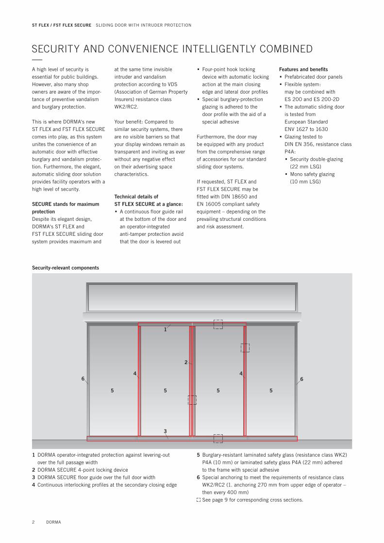
Security-relevant components
1
2
3
4 4
5 5 5 5
6 6
1 DORMA operator-integrated protection against levering-out over the full passage width
2 DORMA SECURE 4-point locking device3 DORMA SECURE fl oor guide over the full door width4 Continuous interlocking profi les at the secondary closing edge
5 Burglary-resistant laminated safety glass (resistance class WK2) P4A (10 mm) or laminated safety glass P4A (22 mm) adhered to the frame with special adhesive
6 Special anchoring to meet the requirements of resistance class WK2/RC2 (1. anchoring 270 mm from upper edge of operator – then every 400 mm)
See page 9 for corresponding cross sections.
ST FLEX / FST FLEX SECURE SLIDING DOOR WITH INTRUDER PROTECTION
2 DORMA

Evidence of performance Burglar resistance
Expert statement10-001167-PR02 dated 18. October 2011 (GAS01-C01-05-en-01)
Translation of Expert Statement 10-001167-PR02 dated 6 October 2011
06-0
9 / 5
39
BasisDIN EN 1627 : 2011 Windows, doors, shutters ¬ - Bur-glar resistance - Requirements and classification
DIN EN 1628 : 2011
DIN EN 1629 : 2011
DIN EN 1630 : 2011
Test report 10-001154-PB01-C01-05-de-01 dated 20 December 2010
Result protocol 10-001209-PR01 (EP01-C01-05-de-01) dated 06 July 2011
Result protocol 10-001209-PR02 (EP01-C01-05-de-01) dated 06 July 2011
Design sheetsAnnex 1, pp 1 to 13 Annex 2, pp 1 to 36
Validity Testing for burglar resistance does not allow any statement to be made on any further charac-teristics regarding performance and quality of the construction submitted.
Validity of the expert statement expires with expiry of any one of the above items referred to as basis (standards or test reports).
Notes on publication The ift Guidance Sheet"Conditions and Guidance for the Use of ift Test Reports" applies.
The cover sheet including the type list can be used as an ab-stract.
Contents The expert statement comprises a total of 56 pages
Cover sheet Type list Expert Statement
1 Order 2 Basis of evaluation 3 Evaluation 4 Results and statement
Annex 1 (1 page) Annex 2 (36 pages)
Client DORMA GmbH + Co. KG DORMA Platz 1 58256 EnnepetalGermany
Product Burglar resistant sliding door system, WK2 (RC2)
Designation ST FLEX SECURE / FST FLEX SECURE
Clear opening di-mensions (W x H)
different(see type list)
(Frame) Material
Aluminium, DORMA profile system ST FLEX DORMA operator profiles ES200
Attack side External face
Type of opening
Two leaf / single leaf sliding, with / without glazed side panels, with / without glazed top light 1 -/ 2 - / 3-part
Glazing DIN EN 356 Klasse P4A
Hardware
Multipoint lock Fuhr Type 3 pivoted bold lock with 4 pivoted bolts as per DIN 18251 Class 4; Profile cylinder as per DIN 18252 P2BZ; continuous strike plate; continuous coupling rim ST FLEX; continuous dis-engagement protection in drive; continuous DORMA floor guide track
Installation
As per installation instructions from company DORMA GmbH + Co. KG
Burglar resistance
Resistance Class RC 2*)
*) on the basis of the mentioned test reports and the complementary, change-related specifications
ift Rosenheim 18. October 2011
Robert Krippahl, Dipl.-Ing. (FH) Deputy Head of Testing Department Building Components
Jens Pickelmann Operating Testing Officer Mechanics
DORMA
ST FLEX / FST FLEX SECURE SLIDING DOOR WITH INTRUDER PROTECTION
3

Expert statement10-001167-PR02-(GAS01-CO1-05-de-01) dated 18. October 2011
Client DORMA GmbH + Co. KG, 58256 Ennepetal, Germany
TYPE LIST—No. Tested type Design variants approved by expert statement Evidence / reports requirements
1. Single-panel and double-panel siding door systems with glazed side screens and fanlight
Single-panel and double-panel sliding door systems available: . with and without side screens . with and without fanlight(glazed in one-piece / two-part / 3-part version)
Test report10-001154-PB01-C01-05-de-01 dated 20 December 2010Result protocol 10-001209-PR01 (EP01-C01-05-de-01) and 10-001209-PR02 (EP01-C01-05-de-01)dated 06 July 2011Expert statement10-001167-PR02dated 18 October 2011
2. Single-panel and double-panel sliding door systems with P4A double-glazing, a thickness of 20 mm and single-glazing
Use of . P4A double-glazing with a thickness of 22 mm . P4A single-glazing with a thickness of 10 mm
Test report10-001154-PB01-C01-05-de-01 dated 20 December 2010Result protocol 10-001209-PR01 (EP01-C01-05-de-01) and10-001209-PR02(EP01-C01-05-de-01)dated 06 July 2011Expert statement10-001167-PR02dated 18 October 2011
3. Single-panel and double-panel sliding door systems with a clear passage width of 2500 mm x 3000 mm or 700 mm x 2800 mm
Single-panel and double-panel sliding door systemswith various clear opening dimensions:
Double-panel version: Width 8OO mm – 3000 mm Height 2100 mm – 3100 mmSingle-panel version: Width 700 mm – 3000 mm Height 2100 mm – 3100 mm
FST-Türen (double-panel and single-panel version): Width 900 mm – 3000 mm Height 2100 mm – 3100 mm
Test report10-001154-PB01-C01-05-de-01 dated 20 December 2010Result protocol 10-001209-PR01 (EP01-C01-05-de-01) and10-001209-PR02(EP01-C01-05-de-01)dated 06 July 2011Expert statement10-001167-PR02dated 18 October 2011
4. Single-panel and double-panel sliding door systems with glazed side screens for mounting at solid surrounding walls
Single-panel and double-panel sliding door systems . with and without side screens . for mounting in mullion and transom construction . tested as a burglar-resistant component to resistance class WK2 or higher . with location of profi les / screws in the mullion res. transom area
Test report10-001154-PB01-C01-05-de-01 dated 20 December 2010Result protocol 10-001209-PR01(EP01-C01-05-de-01) and10-001209-PR02(EP01-C01-05-de-01)dated 06 July 2011
ST FLEX / FST FLEX SECURE SLIDING DOOR WITH INTRUDER PROTECTION
4 DORMA

Preparation of adjacent walls by others ST FLEX SECURE FST FLEX SECURE
The adjacent walls must have the following properties to meet the requirements of resistance class WK2/RC2:
Masonry to DIN 1053-1 – Nominal thickness – Crushing resistance of brickwork – Mortar group
≥ 115 mm≥ 12 II
Steel concrete to DIN 1045 – Nominal thickness – Strength class
≥ 100 mm B15
Door parameters ST FLEX SECURE FST FLEX SECURE
Double-panel sliding door – Clear passage width (LW) – Clear passage height (LH) – Door panel weight
800 – 3,000 mm2,100 – 3,100 mmmax. 2 x 160 kg
900 – 3,000 mm2,100 – 3,100 mmmax. 2 x 130 kg
Single-panel sliding door – Clear passage width (LW) – Clear passage height (LH) – Door panel weight
700 – 3,000 mm2,100 – 3,100 mmmax. 1 x 200 kg
900 – 3,000 mm2,100 – 3,100 mmmax. 1 x 150 kg
Versions ST FLEX SECURE FST FLEX SECURE
Profi le systems Universal profi le system with security glazingto DIN EN 356 category P4A 3 3
Universal profi le system with security double-glazing § §
With side screens § §
Combined sensors to DIN 18650 and EN 16005 3 3
Continuous fl oor-integrated guide railThe fl oor guide rail is always required and has to be provided by others!
3 3
Elevation height and depth of operator 150 mm x 180 mm 3 3
Fanlight in one-piece / two-part / 3-part version § §
ST FLEX safety screen § §
Basic module (BM) ST FLEX SECURE FST FLEX SECURE
Modular design 3 3
Microprocessor-controlled – Offfunction programs – Automatic – Permanent Open – Partial Open – Exit Only – Night-/Bank Function
3 3
Automatic reversing 3 3
Ready for connection of DORMA SECURE locking device 3 3
Light curtains 3 3
Adjustment of all basic parameters via integrated display and keys 3 3
24 V output for external accessories 3 3
Read-out error log with error codes 3 3
DCW® bus connection (Protocol DORMA Connect and Work) 3 3
Emergency power supply via rechargeable battery pack § –
3 standard § optional – no
DORMA 5
ST FLEX / FST FLEX SECURE SPECIFICATIONS / TECHNICAL DATA

Additional equipment ST FLEX SECURE FST FLEX SECURE
Manual lock release for DORMA SECURE locking device 3 3
Light barriers § §
Rechargeable battery pack (emergency opening/closing) § 3
Coupling module for connection to EIB or LON building management systems § §
Function module (FM) – 3 door status contacts – Safeguarding of main closing edge & secondary closing edges – Panic closing (Observe corresponding regulations!) – Bell contact – Airlock control – Synchronous operation
§ §
DIN 18650 and EN 16005 function moduleThe DIN 18650 and EN 16005 function module provides tested monitoring of the secondary closing edges for compliance with the German Industrial Standard DIN 18650 and EN 16005
§ §
Technical operator data ST FLEX SECURE FST FLEX SECURE
DORMA SECURE locking device 3 3
Suitable for application in emergency exits and escape routes –
Height 150 mm 150 mm
Overall depth 180 mm 180 mm
Max. opening and closing force 150 N 3 3
Opening speed (incremental setting) 10 – 70 cm/s 10 – 70 cm/s
Closing speed (incremental setting) 10 – 50 cm/s 10 – 50 cm/s
Hold-open time 0 – 180 s 0 – 180 s
Supply voltage, frequency 230 V, 50/60 Hz 230 V, 50/60 Hz
Power consumption 250 W 250 W
Class of protection IP 20 IP 20
Admissible temperature - 20 – + 60 °C - 20 – + 60 °C
Admissible humidity (relative) max. 93 %(non condensing)
max. 93 %(non condensing)
Tested according to Low Voltage Directive and EMC guidelines 3 3
Manufactured to ISO 9001 3 3
3 standard § optional – no
6 DORMA
ST FLEX / FST FLEX SECURE SPECIFICATIONS / TECHNICAL DATA

HORIZONTAL SECTIONS—Door is closed
Corridor-mounted double-panel systems with side screens
Corridor-mounted double-panel systems with side screens – security screens on the inside
Lintel-mounted double-panel systems with side screens
Corridor-mounted single-panel systems with side screens (wall connection, opening to the left/right)
Corridor-mounted single-panel systems with side screens – security screens on the inside (wall connection, opening to the left/right)
Lintel-mounted single-panel systems with side screens (wall connection, opening to the left/right)
LW = Clear passage width B = System width
Cover for manual lock release
Main closing edge
B (B min = 2 x LW + 168)
max. 8 mm
LW
Cover for manual lock release
B (B min = 2 x LW + 310)
max. 8 mm
max. 8 mm
Main closing edge
Cover for manual lock release
LW
Main closing edge
Cover for manual lock release
Main closing edge
B (B min = 1 x LW + 237)
max. 8 mm
LW
Cover for manual lock release
max. 8 mm
max. 8 mm
Main closing edge
B (B min = 1 x LW + 303)
LW
Cover for manual lock release
LW
max. 8 mmMain closing edge
Cover for manual lock release45 mm
max. 8 mm
Cover for manual lock release
LW
max. 8 mm
71 mm
min. 25 mm
45 mm
Cover for manual lock release
max. 8 mm
Cover for manual lock release45 mm
max. 8 mm
LW
Cover for manual lock release
LW
max. 8 mm
71 mm
min. 25 mm
45 mm
Cover for manual lock release
max. 8 mm
Door is open
DORMA 7
ST FLEX / FST FLEX SECURE SECURITY-RELEVANT COMPONENTS SECURITY SCREENS

VERTICAL SECTIONS—
OH Fanlight height
LH Clear passage height
B Clear passage width
LW Clear passage width
FFL Finished fl oor level
Corridor-mounted systems with fl oor-integrated guide rail
Corridor-mounted systems with fl oor-integrated guide rail and fanlight
Lintel-mounted systems for connection to façade (by others) with fl oor-integrated guide rail
40
mm
35 mm
LH
15
0 m
m
min. 20 mm
FFL
40
mm
35 mm
LH
15
0 m
m
FFL
OH
15 mm
min. 20 mm
40
mm
35 mm
LH
15
0 m
m
FFL
8 DORMA
ST FLEX / FST FLEX SECURE SECURITY-RELEVANT COMPONENTS SECURITY SCREENS

DETAILED CROSS SECTIONS—Ceiling connection of fanlight Unlocking of sliding panel
Wall connectionLW
40
mm
FFL
35 mm
OH
15 mm
OH
Connection of fanlight to operator Wall connection
Security feature inside operator Main closing edge – door is closed
Floor guide
DORMA 9
ST FLEX / FST FLEX SECURE SECURITY-RELEVANT COMPONENTS SECURITY SCREENS

CONNECTIONS—
Drive unitControl unit
***
6 x 0.8
each 8 x 0.8
6 x 0.8
3 x
1.5
mm
2
2 x
0.8
1
00
m
10
x 0
.8
10
0 m
4 x
0.8
1
00
m
2 x
0.8
1
00
m
16 A
*
* Safety sensors to monitor the secondary closing edges in accordance with DIN 18650 and EN 16005**Safety sensors to monitor the main closing edge in accordance with DIN 18650 and EN 16005
Emergency pushbutton,close to door
Inside: Pushbutton
Outside: Key switch, code card readerwith floatingcontact or sim.
Programswitch
Activator (combined sensor: activator/safety sensor)
230/240 V AC50/60 Hz
SWITCHES—
Designation Specifi cation Installation system Order No.
On/Off switch White, aluminium, fl ush-mounting, 80 x 80 mm Gira S-Color 19135403150
Radar switch „MAGIC SWITCH”, proximity-typeradar switch responds to movement,for fl ush-mounting, 80 x 80 mm 05076831332
10 DORMA
ST FLEX / FST FLEX SECURE SYSTEM ACCESSORIES
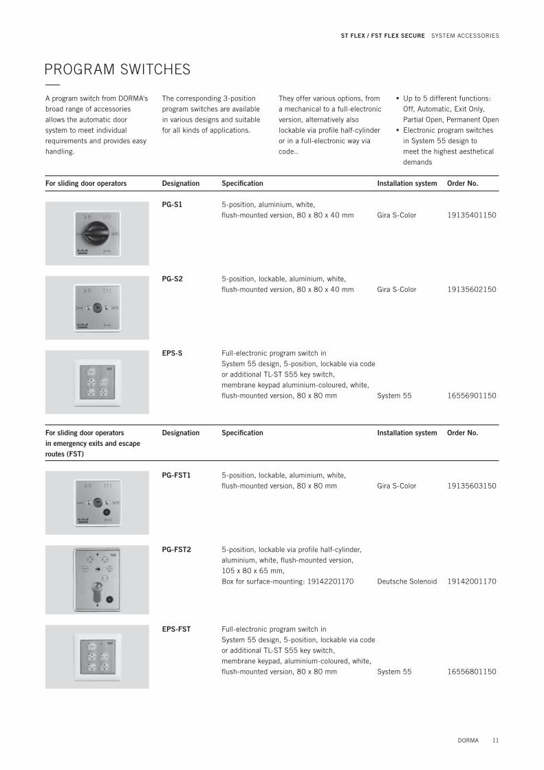
PROGRAM SWITCHES—A program switch from DORMA's broad range of accessories allows the automatic door system to meet individual requirements and provides easy handling.
The corresponding 3-position program switches are available in various designs and suitable for all kinds of applications.
They offer various options, from a mechanical to a full-electronic version, alternatively also lockable via profi le half-cylinder or in a full-electronic way via code..
. Up to 5 different functions: Off, Automatic, Exit Only, Partial Open, Permanent Open . Electronic program switches in System 55 design to meet the highest aesthetical demands
For sliding door operators Designation Specifi cation Installation system Order No.
PG-S1 5-position, aluminium, white, fl ush-mounted version, 80 x 80 x 40 mm Gira S-Color 19135401150
PG-S2 5-position, lockable, aluminium, white, fl ush-mounted version, 80 x 80 x 40 mm Gira S-Color 19135602150
EPS-S Full-electronic program switch in System 55 design, 5-position, lockable via code or additional TL-ST S55 key switch, membrane keypad aluminium-coloured, white, fl ush-mounted version, 80 x 80 mm System 55 16556901150
For sliding door operators in emergency exits and escape routes (FST)
Designation Specifi cation Installation system Order No.
PG-FST1 5-position, lockable, aluminium, white, fl ush-mounted version, 80 x 80 mm Gira S-Color 19135603150
PG-FST2 5-position, lockable via profi le half-cylinder, aluminium, white, fl ush-mounted version, 105 x 80 x 65 mm, Box for surface-mounting: 19142201170 Deutsche Solenoid 19142001170
EPS-FST Full-electronic program switch in System 55 design, 5-position, lockable via code or additional TL-ST S55 key switch, membrane keypad, aluminium-coloured, white, fl ush-mounted version, 80 x 80 mm System 55 16556801150
DORMA 11
ST FLEX / FST FLEX SECURE SYSTEM ACCESSORIES

PUSHBUTTON—Palm pushbutton Designation Specifi cation Installation system Order No.
Single-pole changeover contact, single-type frame, white, fl ush-mounted version System 55 19144701170
Key switches Designation Specifi cation Installation system Order No.
KT 3-1 1 NO contact with profi le half-cylinder, may be replaced for any profi le half-cylinder of a master key system, key only retractable in neutral position, aluminium, metal, 75 x 75 x 60 mm
KT 3-1 UP fl ush-mounted version 05054531332KT 3-1 AP surface-mounted version 05054631332
KT 8 Lettering “Auf, Zu” (German for “Open/Closed”), 2 NO contacts, with profi le half-cylinder, may be replaced for any profi le half-cylinder of a master key system, key only retractable in neutral position, aluminium, metal, 75 x 75 x 60 mm
KT 8 UP fl ush-mounted version 05054831332KT 8 AP surface-mounted version 05054931332
TL-ST S55 Switch with single-pole changeover contact, for profi le half-cylinder by others to DIN 18252, locking cam centre 30 – 32.5 mm, overall length 40.5 – 43,5 mm, locking cam position left (90°), incl. cover for System 55, not suitable for box for surface-mounting, not including profi le half-cylinder, not including frame
TL-ST S55 W White System 55 56330710TL-ST S55 S Silver-coloured System 55 56330701TL-ST S55 A Anthracite System 55 56330715
KT 3-2 1 NO contact with profi le half-cylinder, may be replaced for any profi le half-cylinder of a master key system, key only retractable in neutral position, exchange cover, „Ein/Aus“ lettering (German for „On/Off“), aluminium, fl ush-mounted version: 125 x 100 mm, surface-mounted version: 70 x 90 mm 05054731332
12 DORMA
ST FLEX / FST FLEX SECURE SYSTEM ACCESSORIES

EMERGENCY PUSHBUTTONS—
Designation Specifi cation Installation system Order No.
NAT Designed to interrupt the automatic movement of the door, emergency pushbutton (function: Emergency Off) for automatic door operators, manufactured to ZH 1/494 or BGR 232, DIN 18650 and EN 16005, red knob with yellow centre insert, max. load current: 10 A at 230 V AC
NAT 1 NO contact: 1, NC contact: 1, white frame, fl ush-mounted version, 80 x 80 mm
System 55 90400025
NAT 2no picture
Function “Emergency Opening” with green knob, NO contact: 1, NC contact: 1, max. load current: 10 A at 230 V AC, white frame, fl ush-mounted version, 80 x 80 mm System 55 90400035
NAT 4 NO contact: 1, NC contact: 1, surface-mounted version, 68 x 68 mm
05027031332
TL-N S55 Highly-illuminated emergency pushbutton environment with visual locking status indication, optical and acoustic alarm via yellow fl ashlight and integrated alarm siren, sabotage-proof, behind glass, not including frameNO contact: 1, NC contact: 1, max. load current: 1 A at 24 V DC, fl ush-mounted version, 80 x 80 mm System 55 56330500
ACTIVE INFRARED DETECTOR—Safety sensors Designation Specifi cation Colour Order No.
Prosecure Opti Scan
The active infrared curtain according EN 16005 ensures optimum protection of the area at the side of the door. It protects people in the danger area of the opening door panel.
blacksilver colouredwhite
863011008630210086303100
Prosecure Opti Scan 1
The active infrared curtain according DIN 18650 and EN 16005 ensures optimum protection of the area at the side of the door. It protects people in the danger area of the opening door panel.
blacksilver colouredwhite
863011018630210186303101
Combi sensors Designation Specifi cation Colour Order No.
Prosecure Opti Combi
Quick and easy to install, wide fi eld can be used as a light barrier substitute, LCDDisplay, Precise positioning of the AIR curtain thanks to inclination angle display on a clear scale, direction recognition (DIN 18650 and EN 16005)
blacksilver colouredwhite
867114008671240086713400
Prosecure Opti Combi 1
Very fl exible fi eld settings, active infrared curtain is self-monitoring, crossing traffi c optimization, precise positioning of the AIR curtain thanks to inclination angle display on a clear scale, direction recognition. (DIN 18650 and EN 16005)
blacksilver colouredwhite
867114018671240186713401
DORMA 13
ST FLEX / FST FLEX SECURE SYSTEM ACCESSORIES

MOTION DETECTORS—
Designation Specifi cation Order No.
Prosecure Easy Motion Mono
Full-automatic access on pulse activation; adjustable inclination angle, inclined fi eld of view and fi eld size, LED status indicatorAmbient temperature –20 °C to 60 °C
Black 86001000Silver-coloured 86002000White 86003000
Prosecure Easy Motion Stereo
Adjustable inclination angle, inclined fi eld of view and fi eld size, direction recognition, cross-traffi c suppression, immunity, LED status indicatorAmbient temperature –20 °C to 60 °C
Black 86011000Silver-coloured 86012000White 86013000
Prosecure Opti Motion Mono
Adjustable inclination angle, inclined fi eld of view and fi eld size, direction recognition, immunity, LED status indicatorAmbient temperature –20 °C to 60 °C
Black 86101000Silver-coloured 86102000White 86103000
Prosecure Opti Motion Stereo
Adjustable inclination angle, inclined fi eld of view and fi eld size, direction recognition, cross-traffi c suppression,Slow Motion function, immunity, LED status indicatorAmbient temperature –20 °C to 60 °C
Black 86111000Silver-coloured 86112000White 86113000
Accessories Designation Specifi cation Order No.
Rain protection cover
For Easy Motion detectors 86031900
Rain protection cover/ceiling angle bracket
For Opti Motion detectors 86131900
Prosecure Remote Control
Remote control for programmingProsecure Opti motion detectors or products from other brands; for the convenient and exact adjustment of high-mounted sensors; self-explaining menu navigation, LCD displayAmbient temperature –20 °C to 60 °C 86991900
14 DORMA
ST FLEX / FST FLEX SECURE SYSTEM ACCESSORIES

AUTOSWITCH TRANSPONDER—
Designation Specifi cation Order No.
AutoSwitch The active transponder system activates the control unit of the automatic door when entering the receiver range. Receiver range: approximately 2.5 m; especially suitable for areas where no manual access is desired and as access control system for door systems used by wheelchair users
Receiver/control unit, surface-mounted version, white 16571101175Programming/transponder key, yellow 16571201175Standard/transponder key, blue 16571301175
TRIMS AND BOXES FOR SURFACE-MOUNTED PUSHBUTTONS AND SWITCHES—
Designation Specifi cation Dimensions in mm (W x H x D)
Installation system
Order No.
System 55 Cover frame (Programm STA)
FR-S55 1 Single-type trim, Standard 55, white 80.7 x 80.7 System 55 56391110FR-S55 2 Double-type trim, Standard 55, white 151.8 x 80.7 System 55 56391210FR-S55 3 Triple-type trim, Standard 55, white 223.3 x 80.7 System 55 56391310
FR-E2W 1 Single-type trim, E2 55, white 80.8 x 80.8 System 55 56392110FR-E2W 2 Double-type trim, E2 55, white 151.9 x 80.8 System 55 56392210FR-E2W 3 Triple-type trim, E2 55, white 223.4 x 80.8 System 55 56392310
FR-E2S 1 Single-type trim, E2 55, silver 80.8 x 80.8 System 55 56392101FR-E2S 2 Double-type trim, E2 55, silver 151.9 x 80.8 System 55 56392201FR-E2S 3 Triple-type trim, E2 55, silver 223.4 x 80.8 System 55 56392301
FR-E2A 1 Single-type trim, E2 55, anthracite 80.8 x 80.8 System 55 56392115FR-E2A 2 Double-type trim, E2 55, anthracite 151.9 x 80.8 System 55 56392215FR-E2A 3 Triple-type trim, E2 55, anthracite 223.4 x 80.8 System 55 56392315
Please see STA price list for further trims and versions.
DORMA 15
ST FLEX / FST FLEX SECURE SYSTEM ACCESSORIES

DORMA GmbH + Co. KGDORMA Platz 158256 ENNEPETALGERMANYPhone +49 2333 793-0Fax +49 2333 793-4950www.dorma.com
WN
05
4 0
56
515
32, 0
3/1
3,
ST
FLE
X/F
ST
FLE
X S
EC
UR
E,
GB
, x.
DM
S. xx
/13
Sub
ject
to
chan
ge w
itho
ut n
otic
e


