October 2000 1/303 R ST9+ FAMILY PROGRAMMING MANUAL INTRODUCTION The ST9 8/16 bit microcontroller family introduces a new generation of single-chip architecture. It offers fast program execution, efficient use of memory, sophisticated interrupt handling, input/output (I/O) flexi- bility and bit-manipulation capabilities, with easy system expansion. Virtually all of the ST9 configuration can be tailored to the needs of the user under program control. This enables the ST9 to serve as an I/O intensive microcontroller, as an intelligent peripheral controller within a larger system, or as a memory in- tensive microprocessor. Programming of the ST9 is made easy in both high level languages such as C, or directly in assembler language, by the versatility of the 14 addressing modes coupled with the comprehensive instruction set operating on bits, BCD, 8-bit bytes and 16-bit words. The availability of the Register File, giving the pro- grammer multiple 8- and 16-bit accumulators and index pointers, the fast interrupt response time, on-chip DMA and on-chip and external memory access capabilities, give the ST9 a high efficiency for real-time control applications. The ST9 has a range of family devices made up from various memory combinations (RAM, ROM/ EPROM, FLASH, EEPROM), powerful peripherals such as Multifunction Timers, Analog to Digital Con- verters, Serial Communications Interfaces and a standard Core. Section 1 describes in more detail the ST9 features of primary interest to assembly language program- mers. Please refer to the datasheet of the ST9 device you are using for detailed architectural and configuration information. For a detailed technical introduction to the capabilities of the ST9, refer to the ST9+ User Guide available on the STMicroelectronics website (www.st.com). Note: This Programming Manual follows the syntax of the ST9 Software Tools (High-level Macro Assem- bler running under MS-DOS or Windows). Register and bit names follow the recommendations of the In- clude files in the Include.ST9 directory supplied with the development tools. The ST9 uses 2’s comple- ment arithmetic on 8-bit and 16-bit values. It does not support any floating point types or BCD. The ST9 is byte big endian, i.e. the most significant byte of a 16-bit word has the low address. There is no alignment constraint, i.e. a 16-bit word can be loaded from an odd or even memory address. The ST9 is bit little endian, i.e. the least significant bit of a byte has number 0. 1
Transcript
October 2000 1/303
R ST9+ FAMILY
PROGRAMMING MANUAL
INTRODUCTIONThe ST9 8/16 bit microcontroller family introduces a new generation of single-chip architecture. It offersfast program execution, efficient use of memory, sophisticated interrupt handling, input/output (I/O) flexi-bility and bit-manipulation capabilities, with easy system expansion. Virtually all of the ST9 configurationcan be tailored to the needs of the user under program control. This enables the ST9 to serve as an I/Ointensive microcontroller, as an intelligent peripheral controller within a larger system, or as a memory in-tensive microprocessor.
Programming of the ST9 is made easy in both high level languages such as C, or directly in assemblerlanguage, by the versatility of the 14 addressing modes coupled with the comprehensive instruction setoperating on bits, BCD, 8-bit bytes and 16-bit words. The availability of the Register File, giving the pro-grammer multiple 8- and 16-bit accumulators and index pointers, the fast interrupt response time, on-chipDMA and on-chip and external memory access capabilities, give the ST9 a high efficiency for real-timecontrol applications.
The ST9 has a range of family devices made up from various memory combinations (RAM, ROM/EPROM, FLASH, EEPROM), powerful peripherals such as Multifunction Timers, Analog to Digital Con-verters, Serial Communications Interfaces and a standard Core.
Section 1 describes in more detail the ST9 features of primary interest to assembly language program-mers.
Please refer to the datasheet of the ST9 device you are using for detailed architectural and configurationinformation.
For a detailed technical introduction to the capabilities of the ST9, refer to the ST9+ User Guide availableon the STMicroelectronics website (www.st.com).
Note: This Programming Manual follows the syntax of the ST9 Software Tools (High-level Macro Assem-bler running under MS-DOS or Windows). Register and bit names follow the recommendations of the In-clude files in the Include.ST9 directory supplied with the development tools. The ST9 uses 2’s comple-ment arithmetic on 8-bit and 16-bit values. It does not support any floating point types or BCD.
The ST9 is byte big endian, i.e. the most significant byte of a 16-bit word has the low address. There is noalignment constraint, i.e. a 16-bit word can be loaded from an odd or even memory address.
The ST9 is bit little endian, i.e. the least significant bit of a byte has number 0.
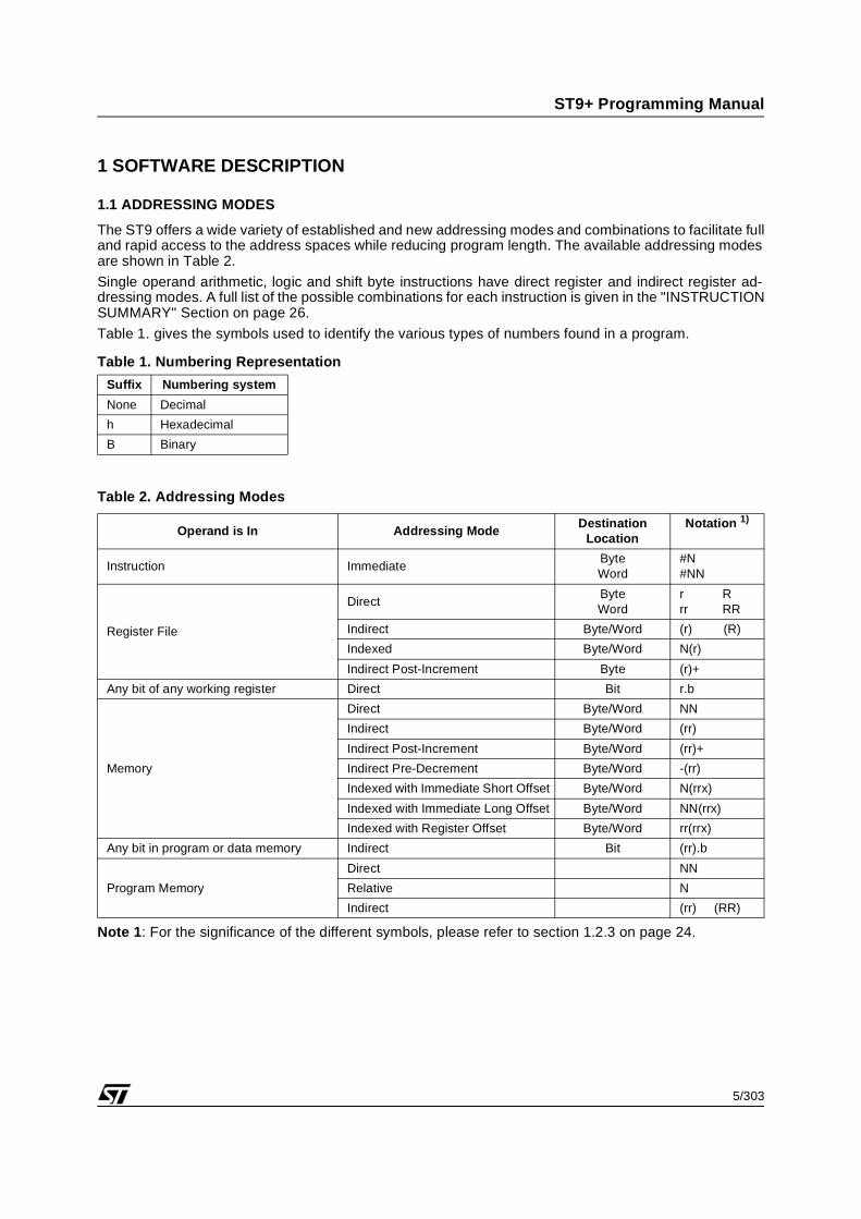
The ST9 offers a wide variety of established and new addressing modes and combinations to facilitate fulland rapid access to the address spaces while reducing program length. The available addressing modesare shown in Table 2.
Single operand arithmetic, logic and shift byte instructions have direct register and indirect register ad-dressing modes. A full list of the possible combinations for each instruction is given in the "INSTRUCTIONSUMMARY" Section on page 26.
Table 1. gives the symbols used to identify the various types of numbers found in a program.
Table 1. Numbering Representation
Table 2. Addressing Modes
Note 1: For the significance of the different symbols, please refer to section 1.2.3 on page 24.
Suffix Numbering system
None Decimal
h Hexadecimal
B Binary
Operand is In Addressing ModeDestination
LocationNotation 1)
Instruction ImmediateByteWord
#N#NN
Register File
DirectByteWord
r Rrr RR
Indirect Byte/Word (r) (R)
Indexed Byte/Word N(r)
Indirect Post-Increment Byte (r)+
Any bit of any working register Direct Bit r.b
Memory
Direct Byte/Word NN
Indirect Byte/Word (rr)
Indirect Post-Increment Byte/Word (rr)+
Indirect Pre-Decrement Byte/Word -(rr)
Indexed with Immediate Short Offset Byte/Word N(rrx)
Indexed with Immediate Long Offset Byte/Word NN(rrx)
Indexed with Register Offset Byte/Word rr(rrx)
Any bit in program or data memory Indirect Bit (rr).b
Program Memory
Direct NN
Relative N
Indirect (rr) (RR)
6/303
ST9+ Programming Manual
ADDRESSING MODES (Continued)
Two Operands Arithmetic and Logic Instructions
Destination Source
Register Direct Register Direct
Register Direct Register Indirect
Register Direct Memory Indirect
Register Direct Memory Indexed
Register Direct Memory Indirect with Post-Increment
Register Direct Memory Indirect with Pre-Decrement
Register Direct Memory Direct
Register Indirect Register Direct
Memory Indirect Register Direct
Memory Indexed Register Direct
Memory Indirect with Post-Increment Register Direct
Memory Indirect with Pre-Decrement Register Direct
Memory Direct Register Direct
Register Direct Immediate
Memory Direct Immediate
Memory Indirect Immediate
7/303
ST9+ Programming Manual
ADDRESSING MODES (Continued)
Notes:1. Word Instructions Only2. Load Byte Only
Two Operands Load Instructions
Destination Source
Register Direct Register Direct
Register Direct Register Indirect
Register Direct Register Indexed
Register Direct Memory Indirect
Register Direct Memory Indexed
Register Direct Memory Indirect with Post-Increment
Register Direct Memory Indirect with Pre-Decrement
Register Direct Memory Direct
Register Indirect Register Direct
Register Indexed Register Direct
Memory Indirect Register Direct
Memory Indexed Register Direct
Memory Indirect with Post-Increment Register Direct
Memory Indirect with Pre-Decrement Register Direct
Memory Direct Register Direct
Register Direct Immediate
Memory Direct Immediate
Memory Indirect Immediate
Memory Indexed 1) Immediate
Two Operands Load Instructions2)
Destination Source
Register Indirect with Post-Increment Memory Indirect with Post-Increment
Memory Indirect with Post-Increment Register Indirect with Post-Increment
Memory Indirect with Post-Increment Memory Indirect with Post-Increment
8/303
ST9+ Programming Manual
ADDRESSING MODES (Continued)
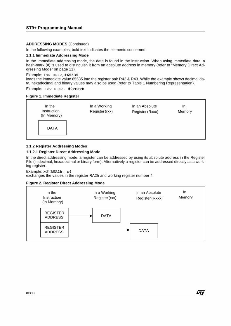
In the following examples, bold text indicates the elements concerned.
1.1.1 Immediate Addressing ModeIn the Immediate addressing mode, the data is found in the instruction. When using immediate data, ahash-mark (#) is used to distinguish it from an absolute address in memory (refer to “Memory Direct Ad-dressing Mode” on page 11).
Example: ldw RR42,#65535loads the immediate value 65535 into the register pair R42 & R43. While the example shows decimal da-ta, hexadecimal and binary values may also be used (refer to Table 1 Numbering Representation).
Example: ldw RR42, #0FFFFh
Figure 1. Immediate Register
1.1.2 Register Addressing Modes
1.1.2.1 Register Direct Addressing ModeIn the direct addressing mode, a register can be addressed by using its absolute address in the RegisterFile (in decimal, hexadecimal or binary form). Alternatively a register can be addressed directly as a work-ing register.
Example: xch R0A2h, r4exchanges the values in the register RA2h and working register number 4.
Figure 2. Register Direct Addressing Mode
In theInstruction
In a WorkingRegister
In an Absolute InMemory
DATA
(In Memory)(rxx) Register (Rxxx)
InMemory
REGISTERADDRESS DATA
REGISTERADDRESS DATA
In a WorkingRegister (rxx)
In theInstruction(In Memory)
In an Absolute
Register (Rxxx)
9/303
ST9+ Programming Manual
ADDRESSING MODES (Continued)
1.1.2.2 Register Indirect Addressing Mode
In the Register Indirect Addressing mode, the address of the data does not appear in the instruction butis located in a working register. The address of this register is given in the instruction. The indirect ad-dressing mode is indicated by the use of parentheses.
Example: If register 200 contains 178 and working register 11 contains 86 then the instruction ld(r11),R200 loads the value 178 into register 86.
Note: the indirect address can only be contained in a working register.
Figure 3. Register Indirect Addressing Mode
1.1.2.3 Register Indexed Addressing ModeTo address a register using the Indexed mode, an offset value is used to add to an index value (which actsas a base or starting value). The offset value is the Immediate value given in the instruction while the indexvalue is given by the contents of the working register.
Example: if working register 10 contains 55 then the instruction
ld 40(r10),r18
loads register 95 (i.e.55+40) with the contents of working register 18.
The Register File never needs an absolute value requiring more than one byte and therefore only requiresa short offset and a single register to contain the index.
Note: The index value can only be contained in a working register.
Figure 4. Register Indexed Addressing Mode
InMemory
REGISTERADDRESS ADDRESS DATA
In a WorkingRegister (rxx)
In an AbsoluteRegister (Rxxx)
In theInstruction(In Memory)
InMemory
REGISTERADDRESS ADDRESS DATA
OFFSET
+
In a WorkingRegister (rxx)
In an Absolute
Register (Rxxx)
In theInstruction(In Memory)
10/303
ST9+ Programming Manual
ADDRESSING MODES (Continued)
1.1.2.4 Register Indirect Addressing Mode with Post-increment
In this addressing mode, both destination and source addresses are given by the contents of working reg-isters which are then post-incremented. The address of the memory location is contained in a working reg-ister pair, and the address of the register is contained into a single working register. Only working registersmay be used to contain the addresses, this mode being indicated by both source and destination usingparentheses followed by plus sign.
Example: if working register 8 contains the value 44, working register pair rr2 contains the value 2000, andregister 44 contains the value 56, then by using the instructionld (rr2),(r8)+
the memory location 2000 will be loaded with the value 56. Immediately following this, the contents of r8is incremented to 45.
When using Register Indirect Addressing Mode with Post-increment in combiniation with Memory IndirectAddressing Mode with Post-increment, blocks of data can be moved either from Register File to Memoryor from Memory to Register File.
Figure 5. Register Indirect Addressing Mode with Post-increment
1.1.2.5 Register Direct Bit Addressing ModeIn the direct bit addressing mode, any bit in any working register can be addressed
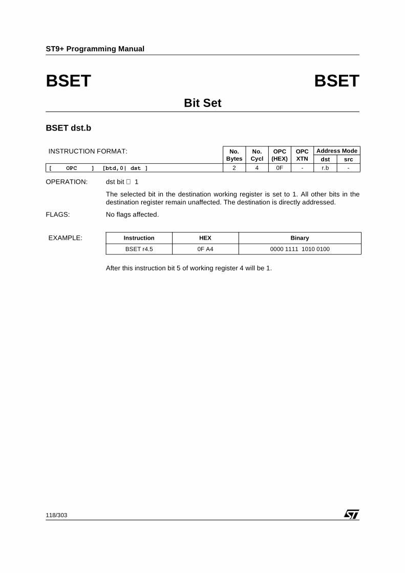
Examples: bset r7.3
This instruction sets the bit 3 of the working register 7.
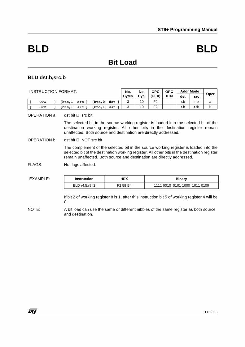
bld r7.3, r12.6
This instruction loads the bit 6 of the working register 12 in bit 3 of working register 7.
InMemory
REGISTERADDRESS ADDRESS DATA
+ 1
In a WorkingRegister (rxx)
In an Absolute
Register (Rxxx)
In theInstruction(In Memory)
11/303
ST9+ Programming Manual
ADDRESSING MODES (Continued)
1.1.3 Memory Addressing Modes
The memory addressing modes described in this section are available to data and program memory. Thusbefore addressing the memory, it is necessary to indicate by use of the Set Program/Data Memory in-structions, spm and sdm, in which memory the instructions are working. Since each memory space is 64Kbyte long, a word address is necessary to specify memory locations.
1.1.3.1 Memory Direct Addressing ModeThe Memory Direct addressing mode requires the specific location within the memory. This only needsthe absolute offset value which can be given in decimal, hex or binary form.
Thus the instruction:ld 12345,r9
loads working register 9 data into memory location 12345
In the memory direct mode, it is possible to use an immediate addressing mode for the source operand.
Examples:ld 12345,#34
will load the value 34 into the memory location 12354.ldw 12345,#3457
will load the location pair 12354 and 12355 with the value 3457.
Figure 6. Memory Direct Addressing Mode
InMemory
DATAADDRESSHIGH
ADDRESSLOW
In a WorkingRegister (rxx)
In an Absolute
Register (Rxxx)
In theInstruction(In Memory)
12/303
ST9+ Programming Manual
ADDRESSING MODES (Continued)
1.1.3.2 Memory Indirect Addressing Mode
When using the indirect addressing mode to access memory, the address is contained in a pair of workingregisters.
Example: if the working register pair r8 and r9 contains the value 2000 then the instruction
ld (rr8),#34
loads the value 34 into memory location 2000.
If the data to be stored is a word then the instruction ldw will automatically interpret the address as a pairof memory locations. So if rr8 contains 2000 then the instructionldw (rr8),#3467
loads the memory locations 2000 and 2001 with the value 3467.
Figure 7. Memory Indirect Addressing Mode
InMemory
DATAADDRESS
HIGH
ADDRESSLOW
REGISTERADDRESS
In a WorkingRegister (rxx)
In an Absolute
Register (Rxxx)
In theInstruction(In Memory)
13/303
ST9+ Programming Manual
ADDRESSING MODES (Continued)
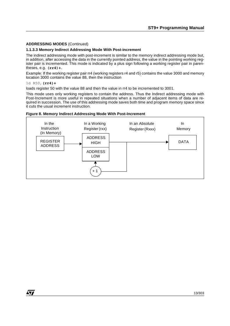
1.1.3.3 Memory Indirect Addressing Mode With Post-increment
The indirect addressing mode with post-increment is similar to the memory indirect addressing mode but,in addition, after accessing the data in the currently pointed address, the value in the pointing working reg-ister pair is incremented. This mode is indicated by a plus sign following a working register pair in paren-theses, e.g. (rr4)+.
Example: If the working register pair rr4 (working registers r4 and r5) contains the value 3000 and memorylocation 3000 contains the value 88, then the instruction
ld R50,(rr4)+
loads register 50 with the value 88 and then the value in rr4 to be incremented to 3001.
This mode uses only working registers to contain the address. Thus the Indirect addressing mode withPost-Increment is more useful in repeated situations when a number of adjacent items of data are re-quired in succession. The use of this addressing mode saves both time and program memory space sinceit cuts the usual increment instruction.
Figure 8. Memory Indirect Addressing Mode With Post-Increment
ADDRESSHIGH
ADDRESSLOW
InMemory
REGISTERADDRESS
DATA
+ 1
In a WorkingRegister (rxx)
In an Absolute
Register (Rxxx)
In theInstruction(In Memory)
14/303
ST9+ Programming Manual
ADDRESSING MODES (Continued)
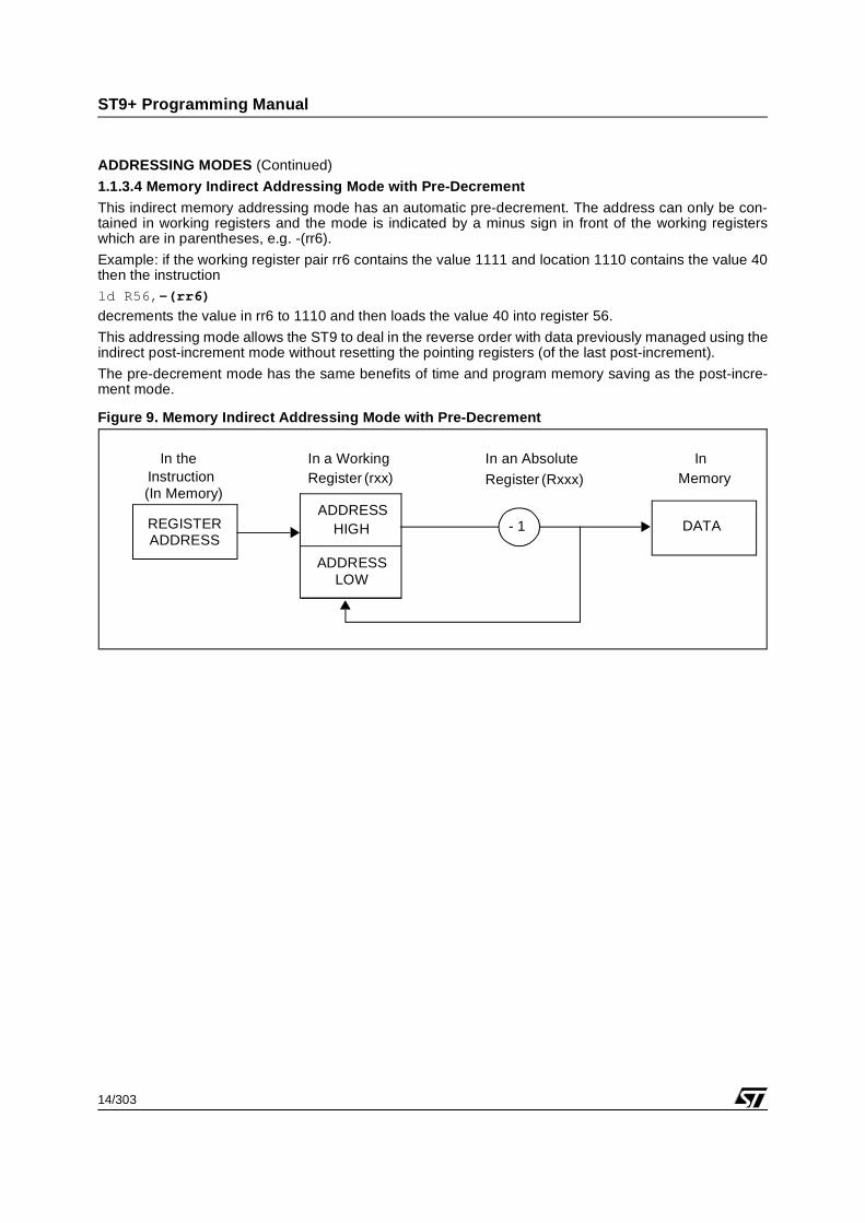
1.1.3.4 Memory Indirect Addressing Mode with Pre-Decrement
This indirect memory addressing mode has an automatic pre-decrement. The address can only be con-tained in working registers and the mode is indicated by a minus sign in front of the working registerswhich are in parentheses, e.g. -(rr6).
Example: if the working register pair rr6 contains the value 1111 and location 1110 contains the value 40then the instructionld R56,-(rr6)
decrements the value in rr6 to 1110 and then loads the value 40 into register 56.
This addressing mode allows the ST9 to deal in the reverse order with data previously managed using theindirect post-increment mode without resetting the pointing registers (of the last post-increment).
The pre-decrement mode has the same benefits of time and program memory saving as the post-incre-ment mode.
Figure 9. Memory Indirect Addressing Mode with Pre-Decrement
ADDRESSHIGH
ADDRESSLOW
InMemory
REGISTERADDRESS
DATA- 1
In a WorkingRegister (rxx)
In an Absolute
Register (Rxxx)
In theInstruction(In Memory)
15/303
ST9+ Programming Manual
ADDRESSING MODES (Continued)
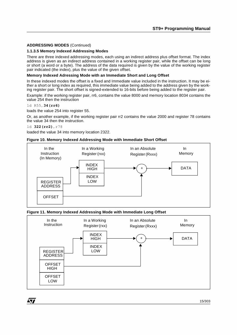
1.1.3.5 Memory Indexed Addressing Modes
There are three indexed addressing modes, each using an indirect address plus offset format. The indexaddress is given as an indirect address contained in a working register pair, while the offset can be longor short (a word or a byte). The address of the data required is given by the value of the working registerpair indicated (the index), plus the value of the given offset.
Memory Indexed Adressing Mode with an Immediate Short and Long Offset
In these indexed modes the offset is a fixed and Immediate value included in the instruction. It may be ei-ther a short or long index as required, this immediate value being added to the address given by the work-ing register pair. The short offset is signed-extended to 16-bits before being added to the register pair.
Example: if the working register pair, rr6, contains the value 8000 and memory location 8034 contains thevalue 254 then the instruction
ld R55,34(rr6)
loads the value 254 into register 55.
Or, as another example, if the working register pair rr2 contains the value 2000 and register 78 containsthe value 34 then the instruction.
ld 322(rr2),r78
loaded the value 34 into memory location 2322.
Figure 10. Memory Indexed Addressing Mode with Immediate Short Offset
Figure 11. Memory Indexed Addressing Mode with Immediate Long Offset
INDEXHIGH
INDEXLOW
InMemory
REGISTERADDRESS
DATA
OFFSET
+
In a WorkingRegister (rxx)
In an Absolute
Register (Rxxx)
In theInstruction(In Memory)
INDEXHIGH
INDEXLOW
In theInstruction
InMemory
REGISTERADDRESS
DATA
OFFSET
+
HIGH
OFFSETLOW
In a WorkingRegister (rxx)
In an Absolute
Register (Rxxx)
16/303
ST9+ Programming Manual
ADDRESSING MODES (Continued)
Memory Indexed Addressing Mode with a Register Offset
In this addressing mode, the index is supplied by one pair of working registers and the offset is suppliedby a second pair of working registers. The format is rrx(rry), x and y being in the range 0,2,4...12,14.
Example: If working register pair rr0 contains the value 2222 and working register pair rr4 contains 3333while register 45 contains the value 78 then the instructionld rr4(rr0),R45
loads the value 78 into memory location 5555.
Figure 12. Memory Indexed Addressing Mode with Register Offset
1.1.3.6 Memory Indirect Bit Addressing Mode
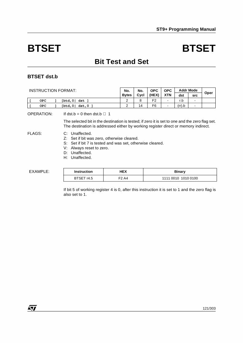
In the memory indirect bit addressing mode, any bit of Program/Data memory location can be addressedwith the btset (Bit Test and SET) instruction.
Examplebtset (rr8).3
This instruction sets bit 3 of the memory location addressed by the working registers r8, r9 contents.
INDEXHIGH
INDEXLOW
InMemory
REGISTERADDRESS
+
OFFSETHIGH
OFFSETLOW
REGISTERADDRESS
DATA
In a WorkingRegister (rxx)
In an Absolute
Register (Rxxx)In the
Instruction(In Memory)
17/303
ST9+ Programming Manual
ADDRESSING MODES (Continued)
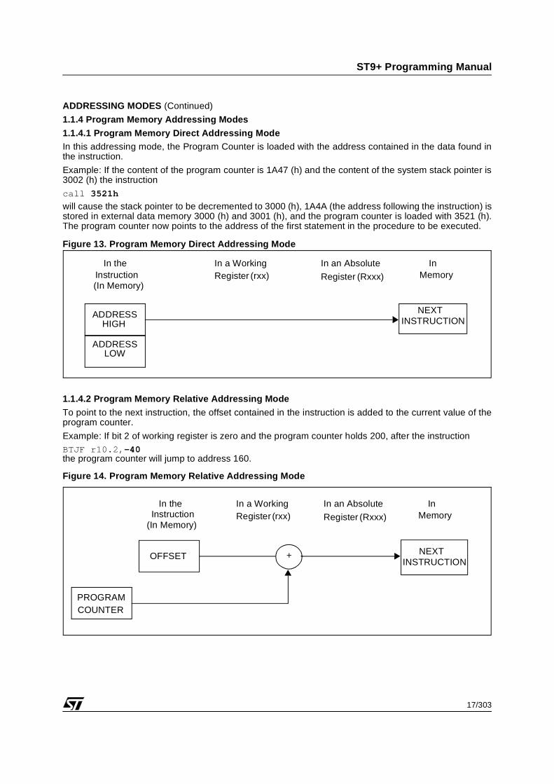
1.1.4 Program Memory Addressing Modes
1.1.4.1 Program Memory Direct Addressing ModeIn this addressing mode, the Program Counter is loaded with the address contained in the data found inthe instruction.
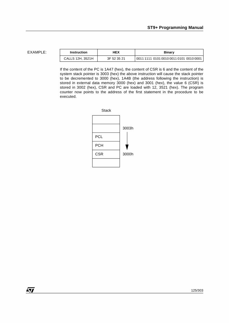
Example: If the content of the program counter is 1A47 (h) and the content of the system stack pointer is3002 (h) the instruction
call 3521h
will cause the stack pointer to be decremented to 3000 (h), 1A4A (the address following the instruction) isstored in external data memory 3000 (h) and 3001 (h), and the program counter is loaded with 3521 (h).The program counter now points to the address of the first statement in the procedure to be executed.
Figure 13. Program Memory Direct Addressing Mode
1.1.4.2 Program Memory Relative Addressing Mode
To point to the next instruction, the offset contained in the instruction is added to the current value of theprogram counter.
Example: If bit 2 of working register is zero and the program counter holds 200, after the instructionBTJF r10.2,-40the program counter will jump to address 160.
Figure 14. Program Memory Relative Addressing Mode
InMemory
ADDRESSHIGH
ADDRESSLOW
INSTRUCTIONNEXT
In a WorkingRegister (rxx)
In theInstruction(In Memory)
In an Absolute
Register (Rxxx)
In theInstruction
InMemory
(In Memory)
INSTRUCTIONNEXT
PROGRAMCOUNTER
+OFFSET
In a WorkingRegister (rxx)
In an Absolute
Register (Rxxx)
18/303
ST9+ Programming Manual
ADDRESSING MODES (Continued)
1.1.4.3 Program Memory Indirect Addressing ModeIn this addressing mode, the address of the next instruction does not appear in the instruction but is locat-ed in a working register or in an absolute register. The address of this register is given in the instruction.Example: If rr6=4321h, the instruction
call rr6
will cause the program counter to be equal to 4321h and to execute the instruction located at this memoryspace.
Figure 15. Program Memory Indirect Addressing Mode using Working Register
Figure 16. Program Memory Indirect Addressing Mode using Absolute Register
In theInstruction
InMemory
(In Memory)
INSTRUCTIONNEXT REGISTER
ADDRESSADDRESS
INSTRUCTIONNEXT
OF
ON 16 BITS
In a WorkingRegister (rxx)
In an Absolute
Register (Rxxx)
In theInstruction
In an AbsoluteRegister
InMemory
(In Memory)
INSTRUCTIONNEXT REGISTER
ADDRESSADDRESS
INSTRUCTIONNEXT
OF
ON 16 BITS
In a WorkingRegister (rxx)
19/303
ST9+ Programming Manual
1.2 INSTRUCTION SET
The ST9+ instruction set consists of 94 instruction types which can be divided into eight groups:
– Load (two operands)
– Arithmetic & logic (two operands)
– Arithmetic Logic and Shift (one operand)
– Stack (one or two operands)
– Multiply & Divide (two or three operands)
– Boolean (one or two operands)
– Program Control (zero to two operands)
– Miscellaneous (zero to two operands)
The wide range of instructions eases use of the register file and memory, reducing operation times, whilethe register pointers mechanism allows an unmatched code efficiency and ultrafast context switching. Aparticularly notable feature is the comprehensive “Any Bit, Any Register” (ABAR) addressing capability ofthe Boolean instructions.
The ST9 can operate with a wide range of data lengths from single bits, 4-bit nibbles which can be in theform of Binary Coded Decimal (BCD) digits, 8-bit bytes, and 16-bit words.
The following summary shows the instructions belonging to each group and the number of operands re-quired for each instruction. The source operand is “src”, “dst” is the destination operand, “cc” is a conditioncode and "N" is a memory relative short address.
Table 3. Load Instructions (Two Operands)
Table 4. Arithmetic and Logic Instructions (Two Operands)
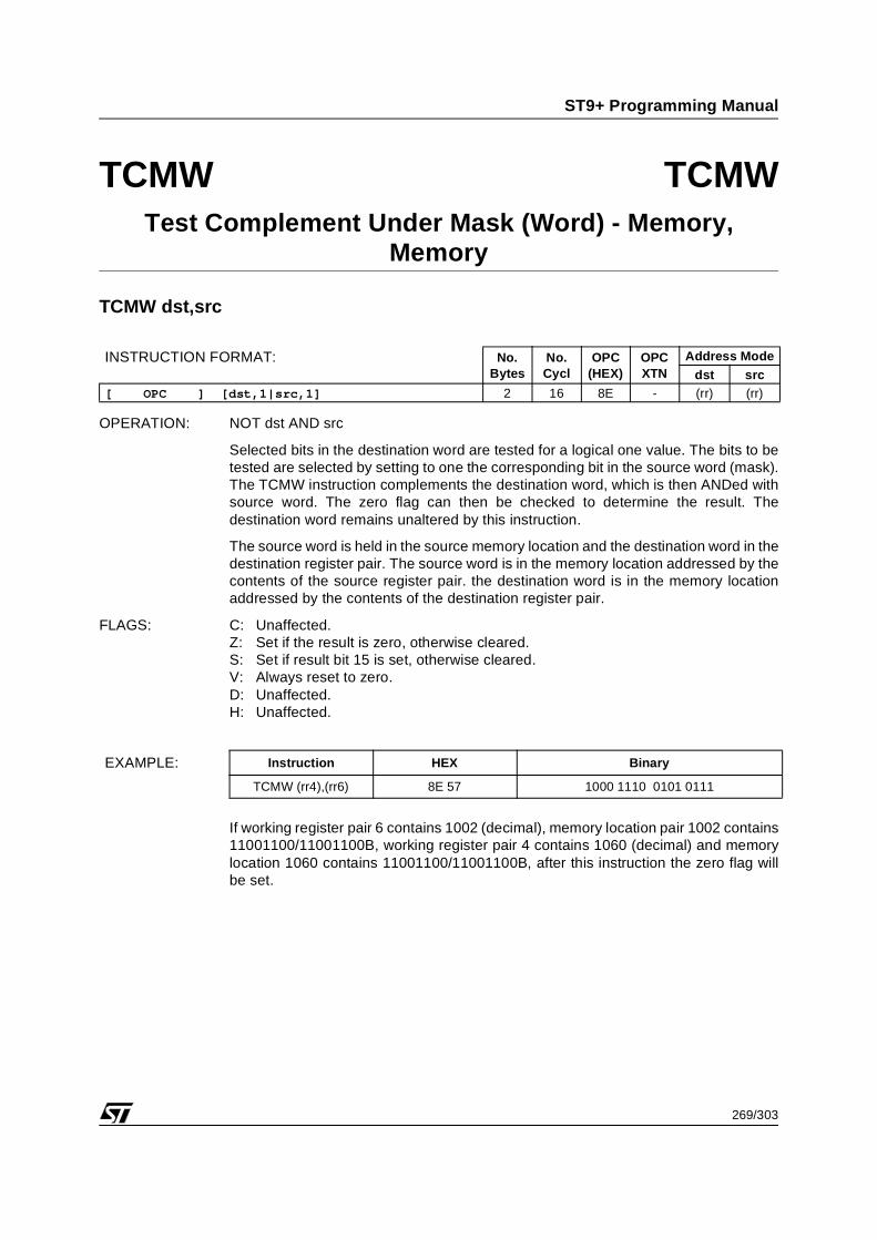
Test Complement Under MaskTest Word Complement Under Mask
20/303
ST9+ Programming Manual
INSTRUCTION SET (Continued)
Table 5. Arithmetic Logic and Shift Instructions (One Operand)
Table 6. Stack Instructions (One or Two Operands)
Table 7. Multiply and Divide Instructions (Two or Three Operands)
Mnemonic Operands Instruction
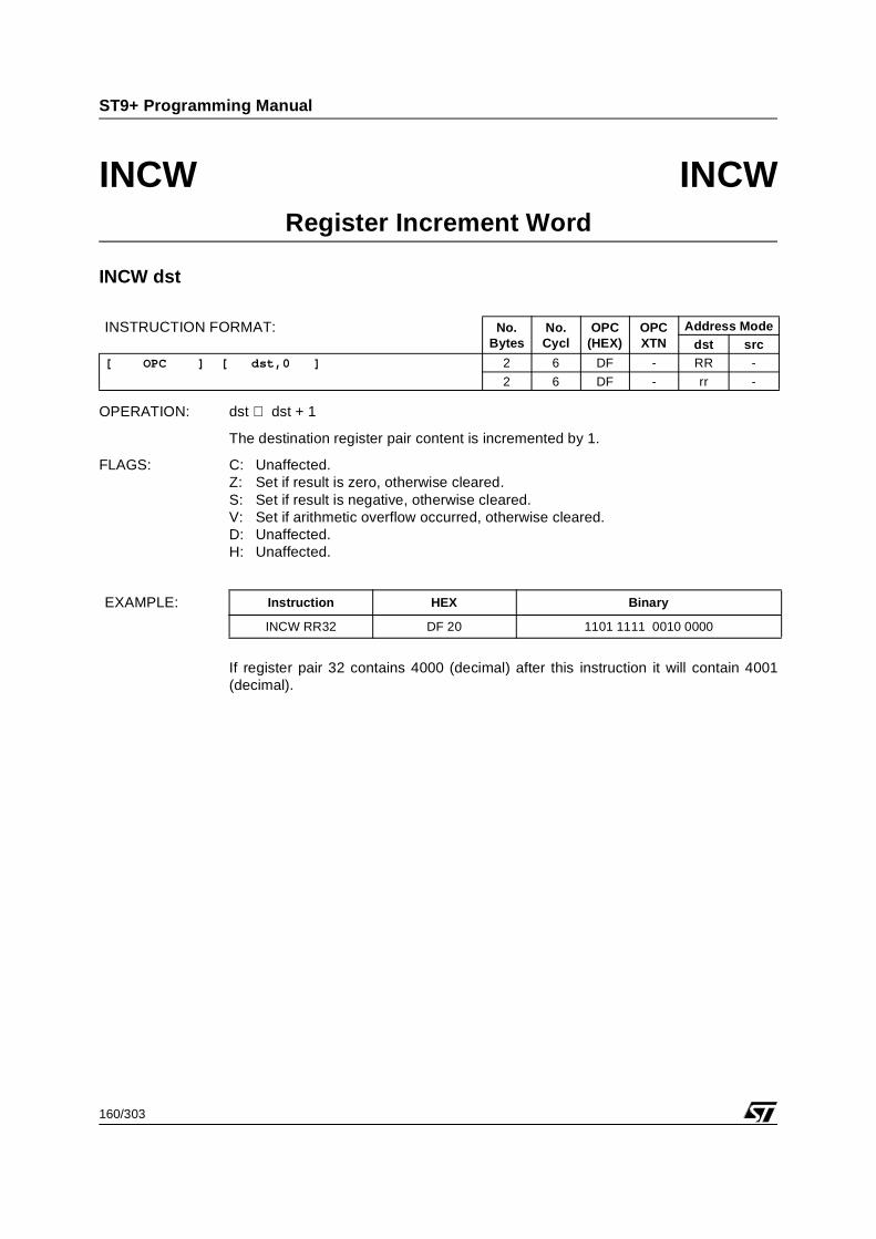
INCINCW
dstdst
IncrementIncrement Word
DECDECW
dstdst
DecrementDecrement Word
SLASLAW
dstdst
Shift Left ArithmeticShift Word Left Arithmetic
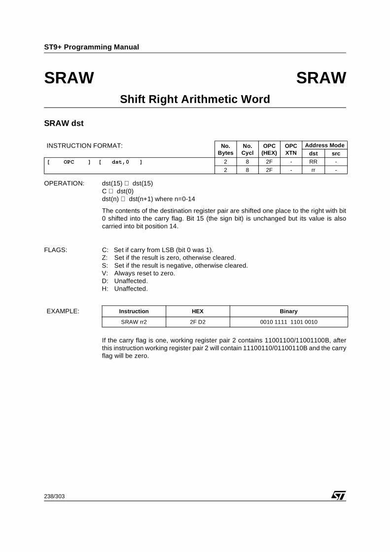
SRASRAW
dstdst
Shift Right ArithmeticShift Word Right Arithmetic
RRCRRCW
dstdst
Rotate Right Through CarryRotate Word Right Through Carry
RLCRLCW
dstdst
Rotate Left Through CarryRotate Word Left Through Carry
ROR dst Rotate Right
ROL dst Rotate Left
CLR dst Clear Register
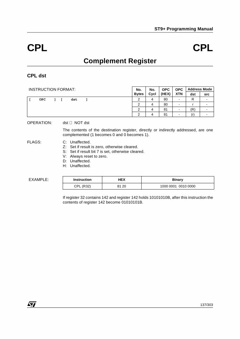
CPL dst Complement Register
SWAP dst Swap Nibbles
DA dst Decimal Adjust
Mnemonic Operands Instruction
PUSHPUSHWPEA
srcsrcsrc
Push on System StackPush Word on System StackPush Effective Address on System Stack
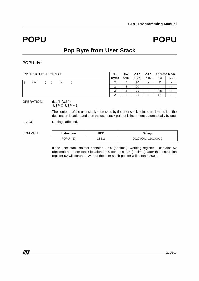
POPPOPW
dstdst
Pop From System StackPop Word from System Stack
PUSHUPUSHUWPEAU
srcsrcsrc
Push on User StackPush Word on User StackPush Effective Address on User Stack
POPUPOPUW
dstdst
Pop From User StackPop Word From User Stack
LINKFrame Pointer, Size (use system stack)
Move Stack Pointer upward; support for high-level language
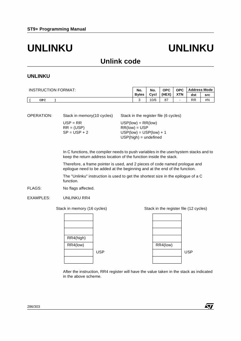
UNLINKFrame Pointer (use system stack)
Move Stack Pointer backward; support for high-level language
LINKUFrame Pointer, Size (use user stack)
Move Stack Pointer upward; support for high-level language
UNLINKUFrame Pointer (use user stack)
Move Stack Pointer backward; support for high-level language
Mnemonic Operands Instruction
MUL dst,src Multiply 8x8
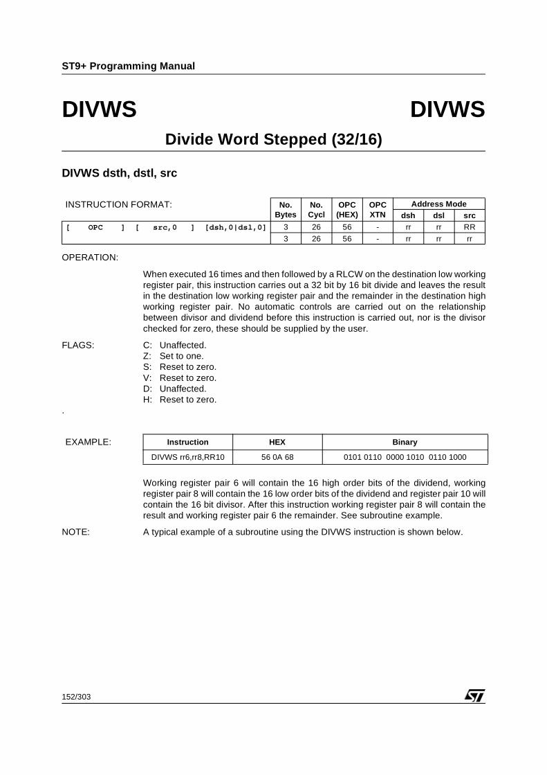
DIVDIVWS
dst,srcdsth,dstl,src
Divide 16/8Divide Word Stepped 32/16
21/303
ST9+ Programming Manual
INSTRUCTION SET (Continued)
Table 8. Boolean Instructions (One or Two Operands)
Table 9. Program Control Instructions (Zero, One, or Two Operands)
Mnemonic Operands Instruction
BSET dst Bit Set
BRES dst Bit Reset
BCPL dst Bit Complement
BTSET dst Bit Test and Set
BLD dst,src Bit Load
BAND dst,src Bit AND
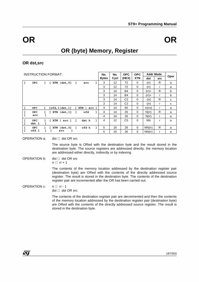
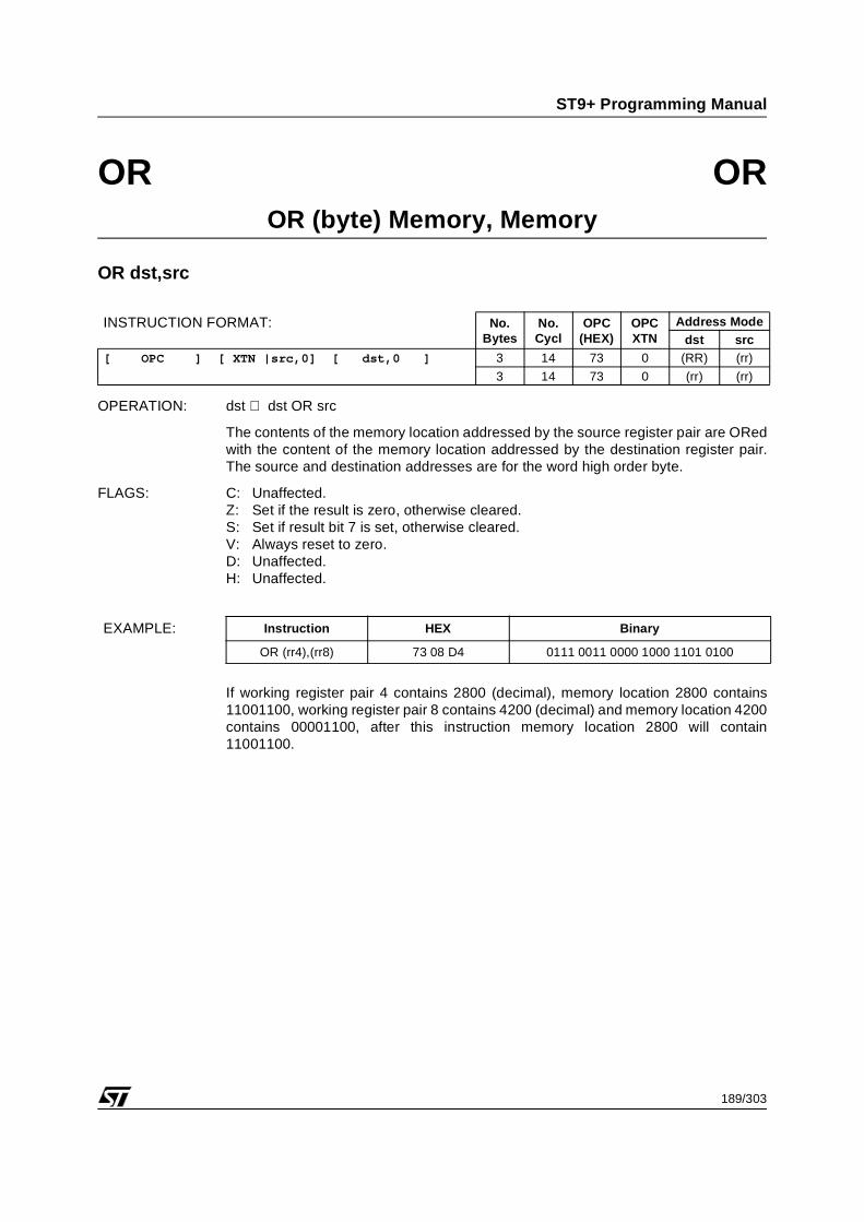
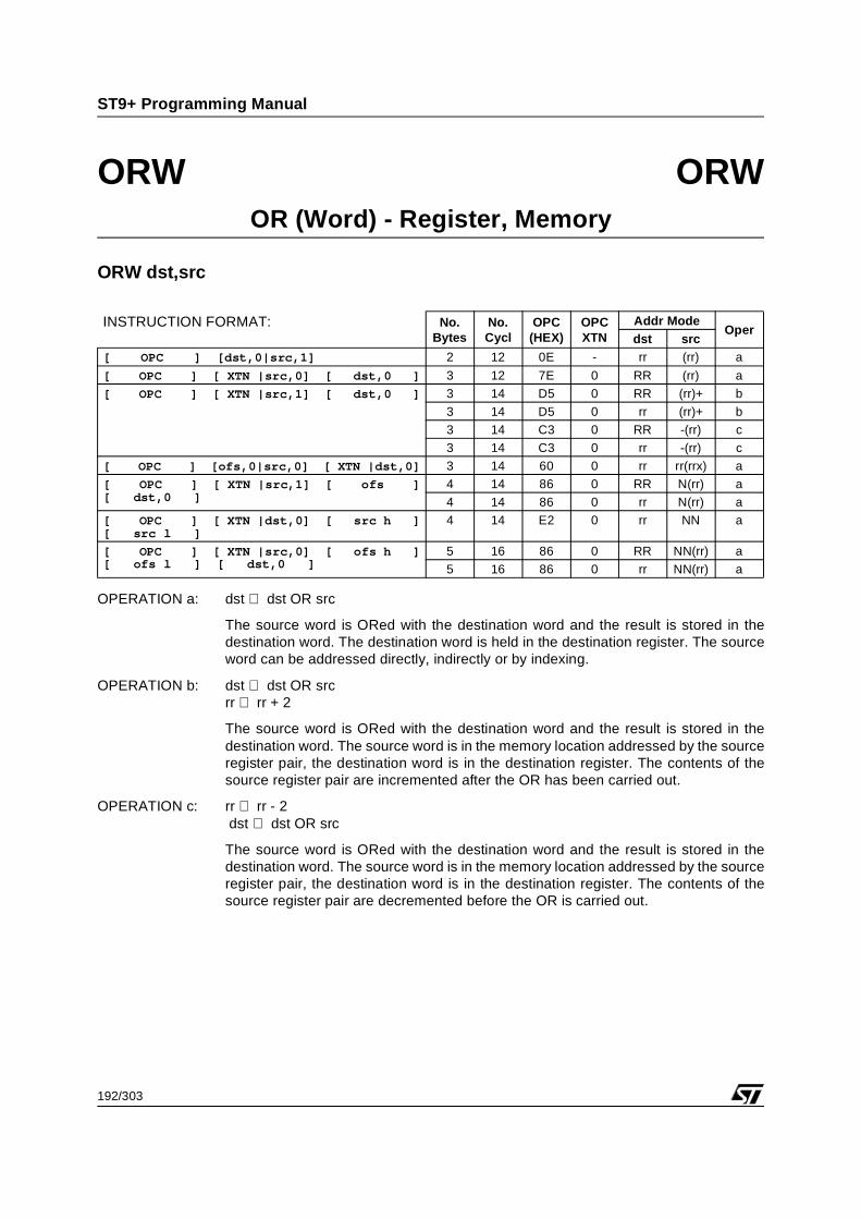
BOR dst,src Bit OR
BXOR dst,src Bit XOR
Mnemonic Operands Instruction
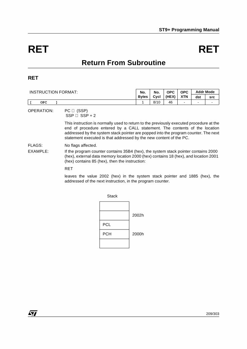
RET Return from Subroutine
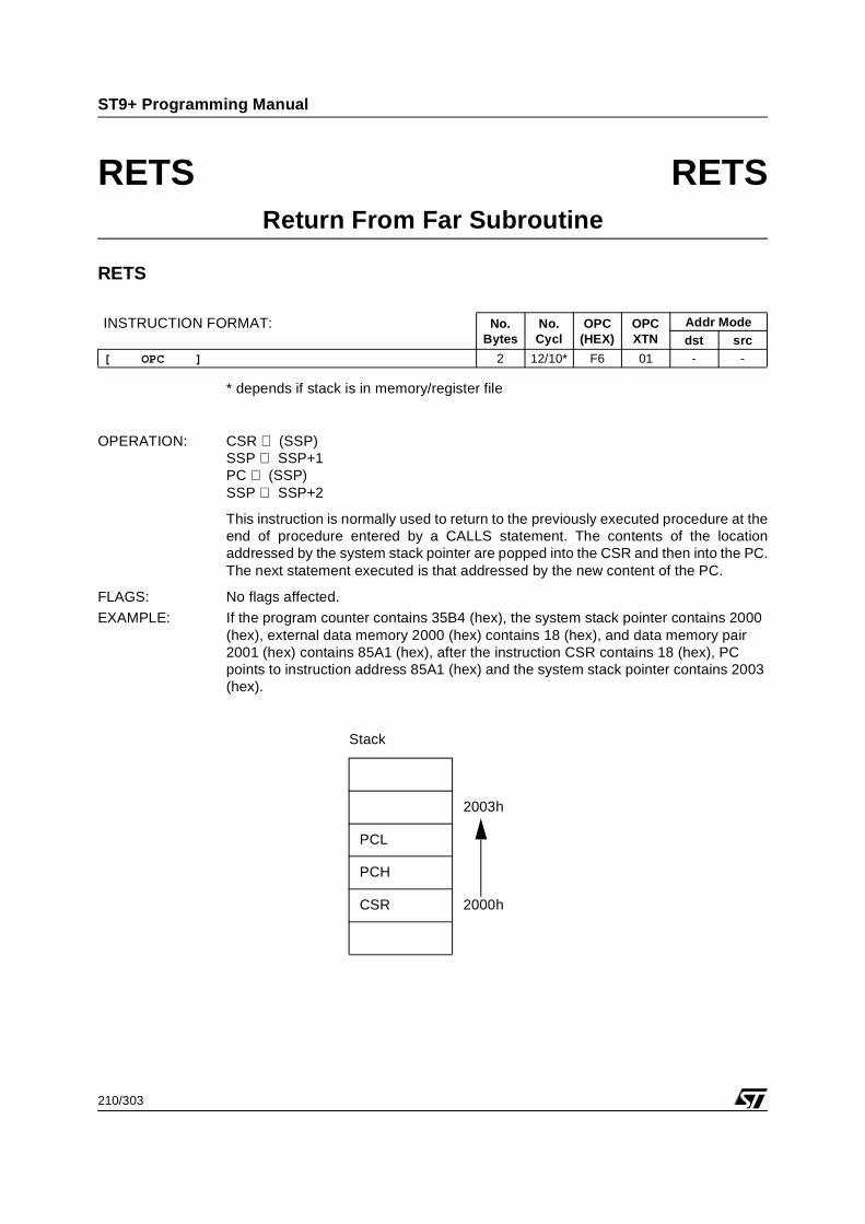
RETS Inter-segment Return to Subroutine
IRET Return from Interrupt
JRcc dst Jump Relative If Condition is Met
JPcc dst Jump if Condition is Met
JP dst Unconditional Jump
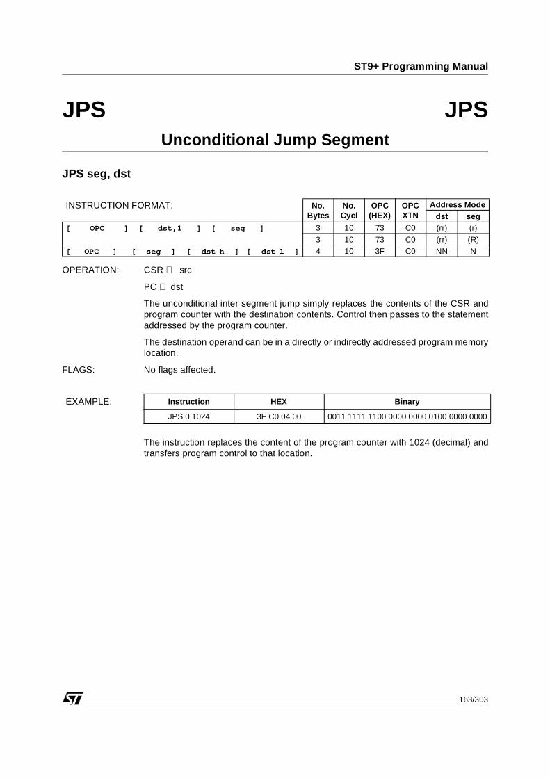
JPS dst 1)
1) There are two operands for JPS and CALLS:- the destination segment (1 byte) - the destination address (2 bytes)
Unconditional Inter-segment Jump
CALL dst Unconditional Call
CALLS dst 1) Inter-segment Call to Subroutine
BTJF src,N Bit Test and Jump if False
BTJT src,N Bit Test and Jump if True
DJNZ dst,NDecrement a Working Register and Jumpif Non Zero
DWJNZ dst,NDecrement a Register Pair and Jump ifNon Zero
CPJFI src1, src2, NCompare and Jump on False. OtherwisePost Increment
CPJTI src1, src2, NCompare and Jump on True. OtherwisePost Increment
22/303
ST9+ Programming Manual
INSTRUCTION SET (Continued)
Table 10. Miscellaneous (None, One or Two Operands)
Mnemonic Operands Instruction
XCH dst,src Exchange Registers
SRP src Set Register Pointer Long (16 working registers)
SRP0 src Set Register Pointer 0 (8 LSB working register)
SRP1 src Set Register Pointer 1 (8 MSB working register)
SPP src Set Page Pointer
EXT dst Sign Extend
EI Enable Interrupts
DI Disable Interrupts
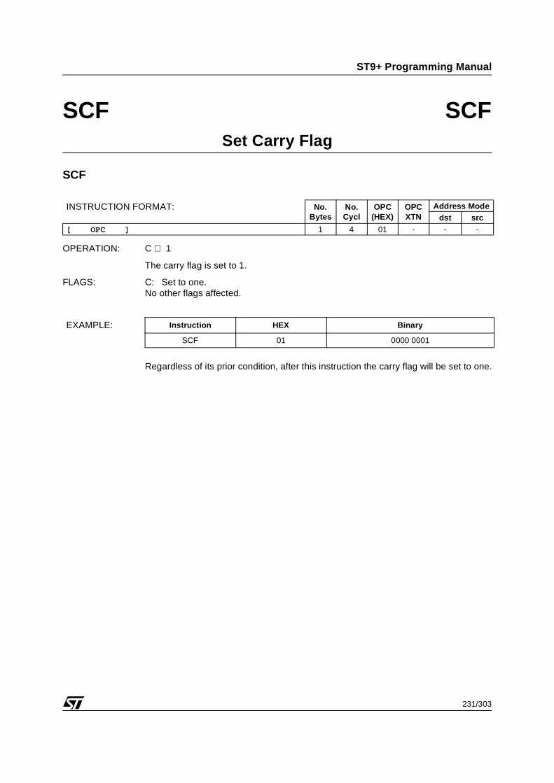
SCF Set Carry Flag
RCF Reset Carry Flag
CCF Complement Carry Flag
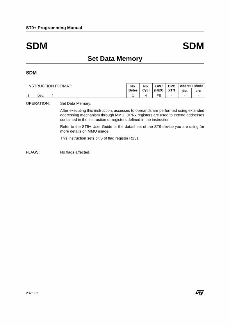
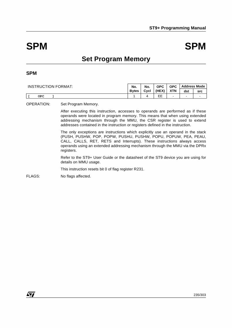
SPM Select Extended Memory addressing scheme through CSR Register
SDM Select Extended Memory addressing scheme through DPRx Registers
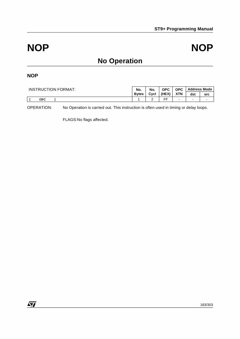
NOP No Operation
WFIStop Program Execution and Wait for the next Enabled Interrupt. If a DMA request is present, the CPU executes the DMA service routine and then automatically returns to the WFI
HALT Stop Program Execution Until Next System Reset
23/303
ST9+ Programming Manual
INSTRUCTION SET (Continued)
1.2.1 ST9 Processor Flags
An important feature of a single chip microcomputer is the ability to test data and make the appropriate ac-tion based on the results. In order to provide this facility, FLAGR (register 231) in the register file is usedas a flag register. Six bits of this register are used as the following flags:
Bit 7: C - Carry
Bit 6: Z - Zero
Bit 5: S - Sign
Bit 4: V - Overflow
Bit 3: D - Decimal Adjust
Bit 2: H - Half Carry
Bit 1 is reserved for emulation, and should be always written as 0.
Bit 0 selects extended memory addressing scheme through CSR or DPRx registers.
The Flag Register is further described in the Architecture Chapter of any datasheet.
1.2.2 Condition Codes
Flags C, Z, S, and OV control the operation of the “conditional” Jump instructions. The next table showsthe condition codes and the flag settings.
Note: Some of the Status flags are used to indicate more than one condition e.g. Zero and Equal. In suchcases the condition code is the same for both conditions.
Table 11. Condition Codes Table
Mnemoniccode
MeaningFlag
settingHex.value
Binaryvalue
F Always False _ _ _ _ 0 0000
T Always True _ _ _ _ 8 1000
C Carry C=1 7 0111
NC Not carry C=0 F 1111
Z Zero Z=1 6 0110
NZ Not Zero Z=0 E 1110
PL Plus S=0 D 1101
MI Minus S=1 5 0101
OV Overflow V=1 4 0100
NOV No Overflow V=0 C 1100
EQ Equal Z=1 6 0110
NE Not Equal Z=0 E 1110
GEGreater Thanor Equal
(S xor V)=0 9 1001
LT Less Than (S xor V)=1 1 0001
GT Greater Than (Z or(S xor V))=0 A 1010
LE Less Than or Equal (Z or(S xor V))=1 2 0010
UGEUnsigned GreaterThan or Equal
C=0 F 1111
ULT Unsigned Less Than C=1 7 0111
UGTUnsignedGreater Than
(C=0 and Z=0)=1 B 1011
ULEUnsigned LessThan or Equal
(C or Z)=1 3 0011
24/303
ST9+ Programming Manual
INSTRUCTION SET (Continued)
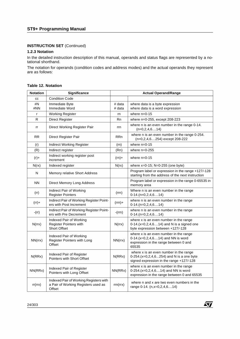
1.2.3 Notation
In the detailed instruction description of this manual, operands and status flags are represented by a no-tational shorthand.
The notation for operands (condition codes and address modes) and the actual operands they representare as follows:
Table 12. Notation
Notation Significance Actual Operand/Range
cc Condition Code
#N#NN
Immediate ByteImmediate Word
# data# data
where data is a byte expressionwhere data is a word expression
r Working Register rn where n=0-15
R Direct Register Rn where n=0-255, except 208-223
rr Direct Working Register Pair rrnwhere n is an even number in the range 0-14. (n=0,2,4,6....14)
RR Direct Register Pair RRn where n is an even number in the range 0-254. (n=0,2,4,6....254) except 208-222
(r) Indirect Working Register (rn) where n=0-15
(R) Indirect register (Rn) where n=0-255
(r)+Indirect working register postincrement
(rn)+ where n=0-15
N(rx) Indexed register N(rx) where x=0-15; N=0-255 (one byte)
N Memory relative Short AddressProgram label or expression in the range +127/-128 starting from the address of the next instruction
NN Direct Memory Long AddressProgram label or expression in the range 0-65535 in memory area
(rr)Indirect Pair of Working Register Pointers
(rrn)Where n is an even number in the range 0-14.(n=0,2,4,6....14)
(rr)+Indirect Pair of Working Register Point-ers with Post Increment
(rrn)+where n is an even number in the range0-14.(n=0,2,4,6....14)
-(rr)Indirect Pair of Working Register Point-ers with Pre Decrement
-(rrn)where n is an even number in the range0-14.(n=0,2,4,6....14)
N(rrx)Indexed Pair of Working Register Pointers withShort Offset
N(rrx)where x is an even number in the range0-14.(x=0,2,4,6....14) and N is a signed onebyte expression between +127/-128
NN(rrx)Indexed Pair of Working Register Pointers with LongOffset
NN(rrx)
where x is an even number in the range0-14.(x=0,2,4,6....14) and NN is wordexpression in the range between 0 and65535
N(RRx)Indexed Pair of Register Pointers with Short Offset
N(RRx) where x is an even number in the range0-254.(x=0,2,4,6...254) and N is a one bytesigned expression in the range +127/-128
NN(RRx)Indexed Pair of Register Pointers with Long Offset
NN(RRx)where x is an even number in the range0-254.(x=0,2,4,6....14) and NN is wordexpression in the range between 0 and 65535
rr(rrx)Indexed Pair of Working Registers with a Pair of Working Registers used as Offset
rrn(rrx) where n and x are two even numbers in therange 0-14. (n,x=0,2,4,6....14)
25/303
ST9+ Programming Manual
Table 13. Flags and Flag Status Symbols
Table 14. Other Symbols
r.b Bit pointer in a direct working register rn.bn=0.15 b is a number between 0-7; 0 is LSB, 7 is MSB
(rr).bBit pointer in a Memory Location using a Pair of Indirect Working Registers asAddress Pointer
(rrn).bwhere n is an even number in the range0-14.(n=0,2,4,6....14) b is a number between 0-7; 0 is LSB, 7 is MSB
(RR) Indirect pair of Register Pointer (RRn) where n is an even number in the range0-255.(n=0,2,4,6....254)
Symbol MeaningC Carry Flag
Z Zero Flag
S Sign Flag
V Overflow Flag
D Decimal Adjust Flag
H Half Carry Flag
^ Affected
- Not affected
0 Reset to zero
1 Set to one
? Undefined
Symbol Meaningdst Destination Operand
src Source Operand
OPC Operation Code
XTN Operation Code Extension
ofs Source Offset
ofd Destination Offset
r.b Bit and Working Register
SSP System Stack Pointer
USP User Stack Pointer
PC Program Counter
CC Condition Code
CIC Central Interrupt Control Register
btd Source Bit of Working Register⇐ Assignment of Result
DP Selection of extended memory addressing scheme through CSR or DPRx registers.
P Refer to “TIMING INFORMATION:” on page 26
D Refer to “TIMING INFORMATION:” on page 26
Notation Significance Actual Operand/Range
26/303
ST9+ Programming Manual
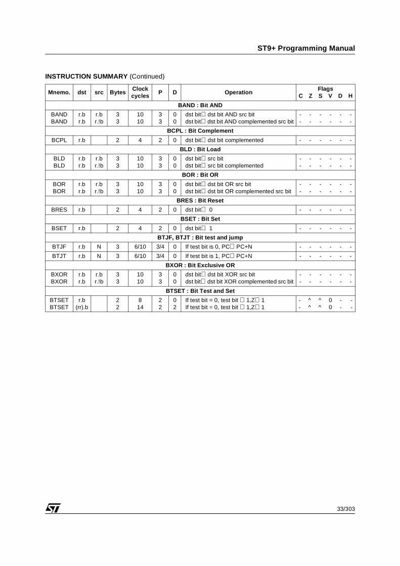
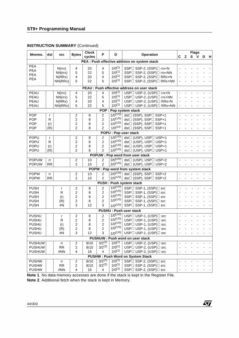
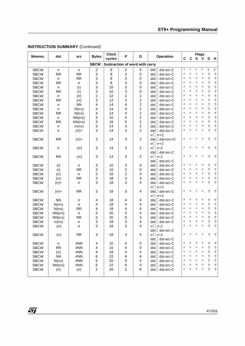
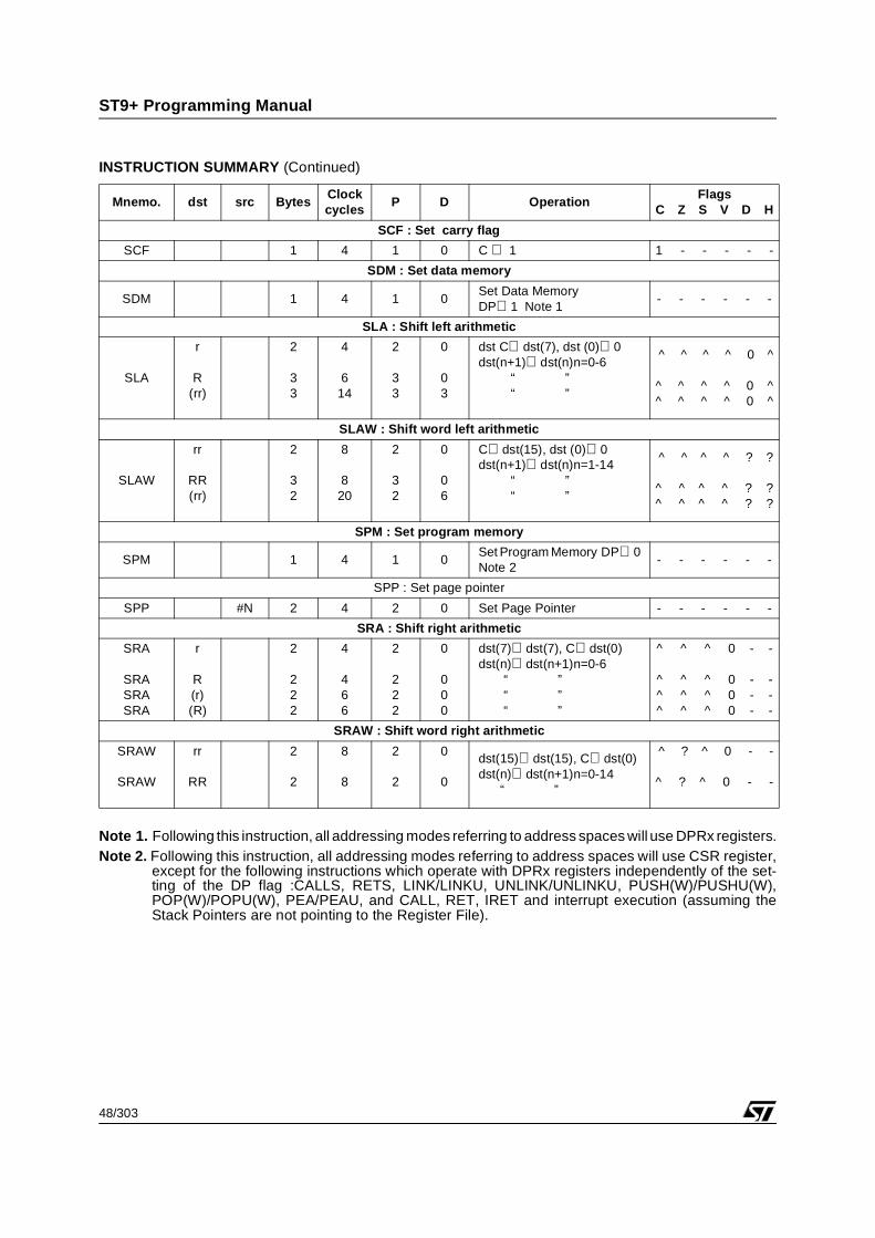
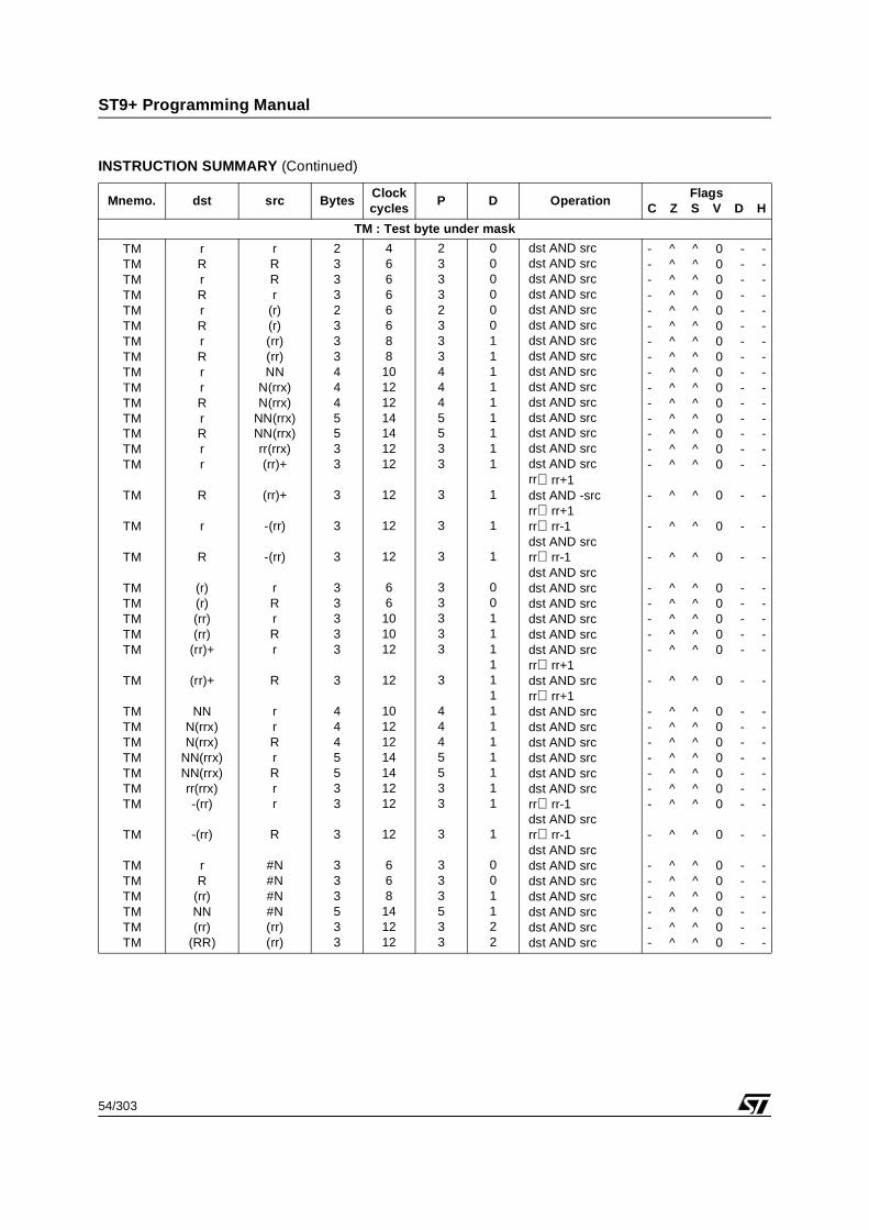
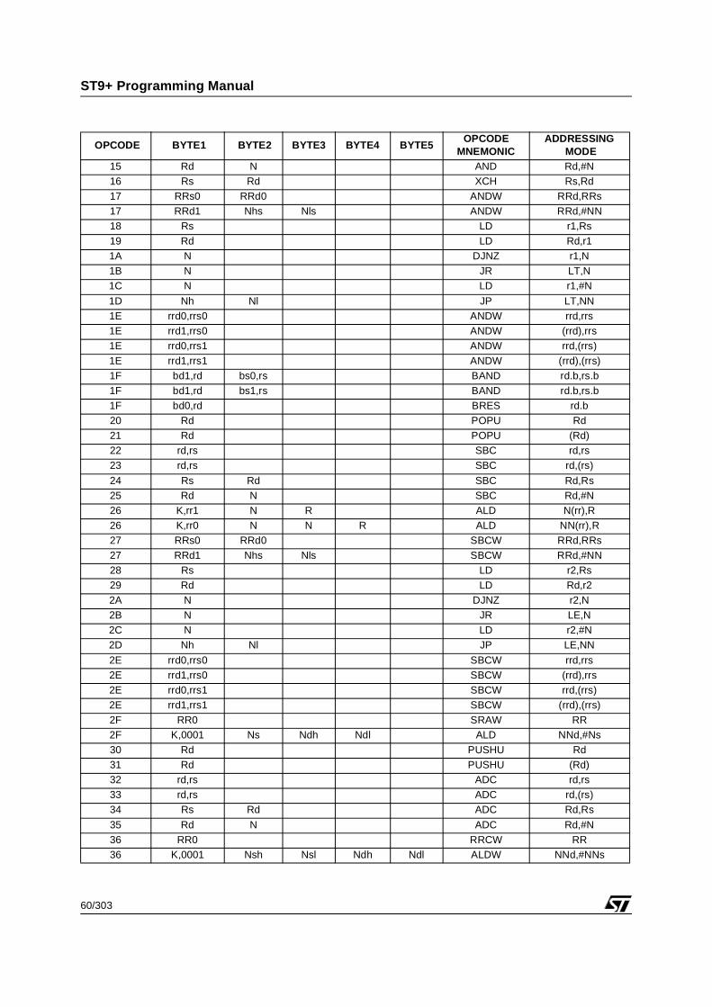
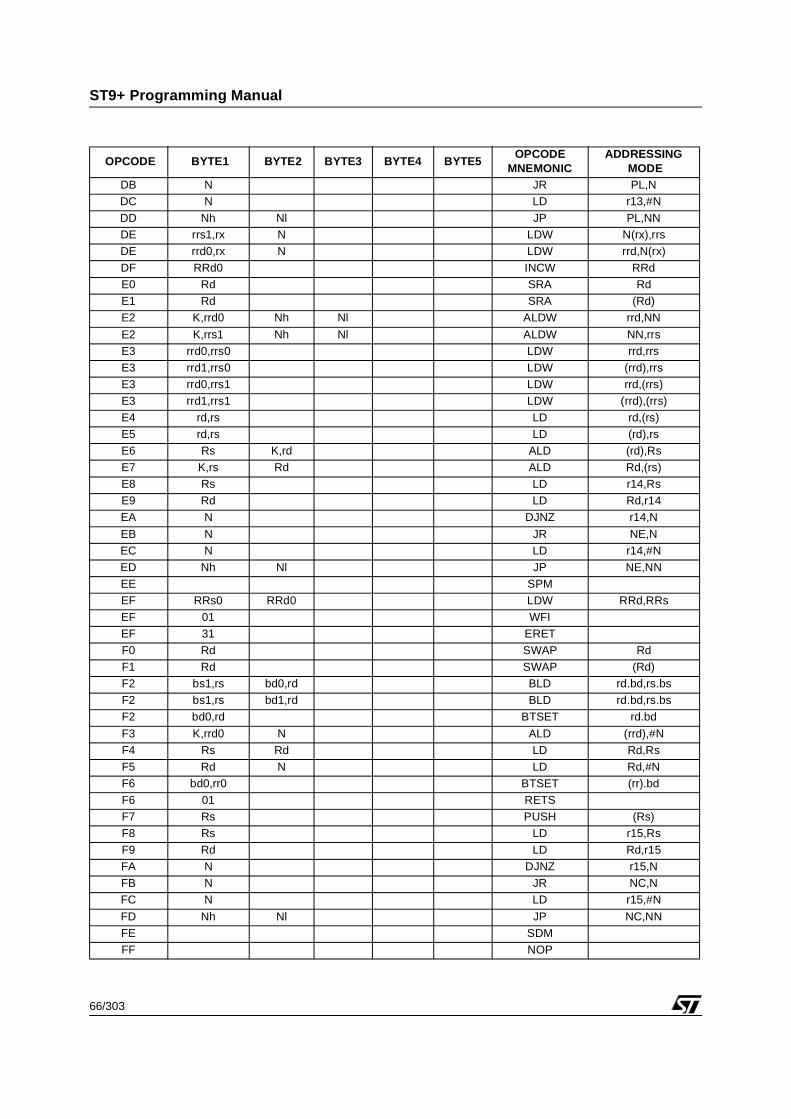
1.3 INSTRUCTION SUMMARY
The following tables summarize the operation for each of the instructions which are listed with their corre-sponding mnemonic codes, addressing modes, byte counts, timing information, and affected flags.
For detailed information on the instruction set, please refer to the Instructions Section on page 68.
For the significance of the different symbols used in these tables, refer to section 1.2.3 on page 24.
TIMING INFORMATION:
The number of clock cycles given is valid when no wait states are added to memory accesses. In order tofacilitate the evaluation of timings when wait states are added to memory access, two additional columnsare given: P and D.
P gives the number of accesses to program memory for instruction fetch: if wait states are added when ac-cessing the memory containing the code, the number of these wait states, multiplied by the value of col-umn P, must be added to the instruction duration.
The same applies to column D, which gives the number of accesses needed for operands; these are typ-ically in data memory, unless (except for stack operations, which are always performed with data memory)bit 0 of the FLAGS register is 0 (e.g. after executing the SPM instruction).
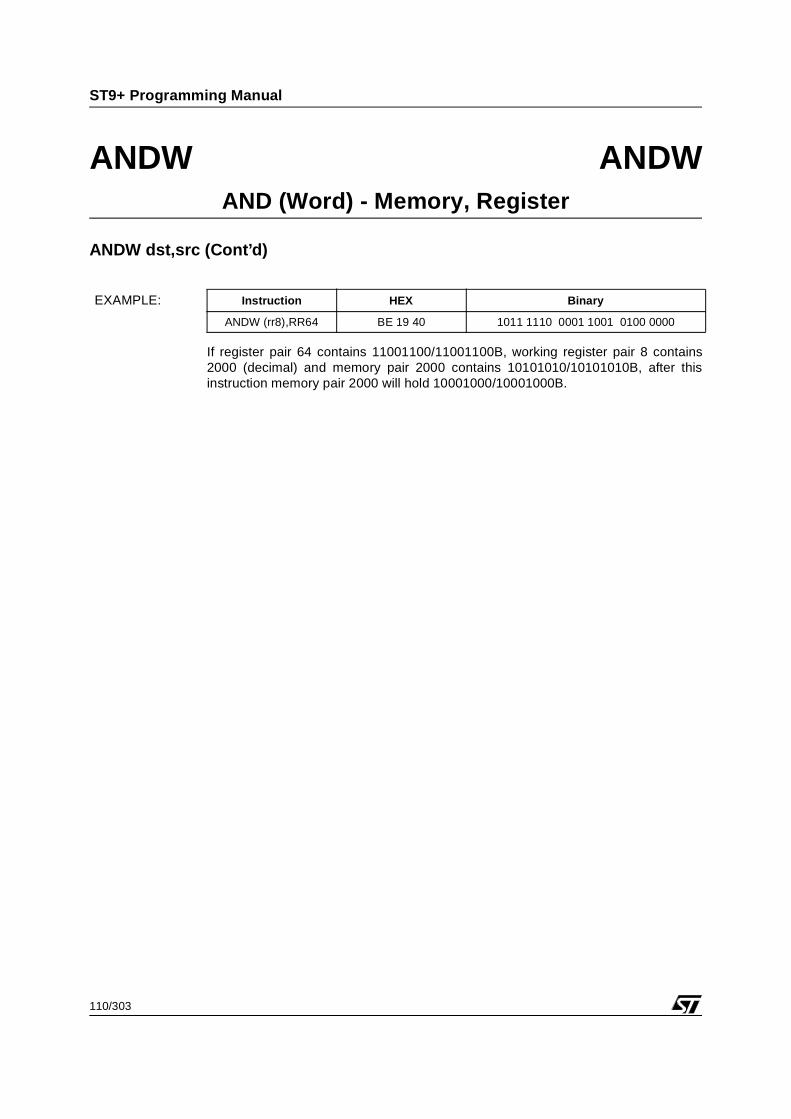
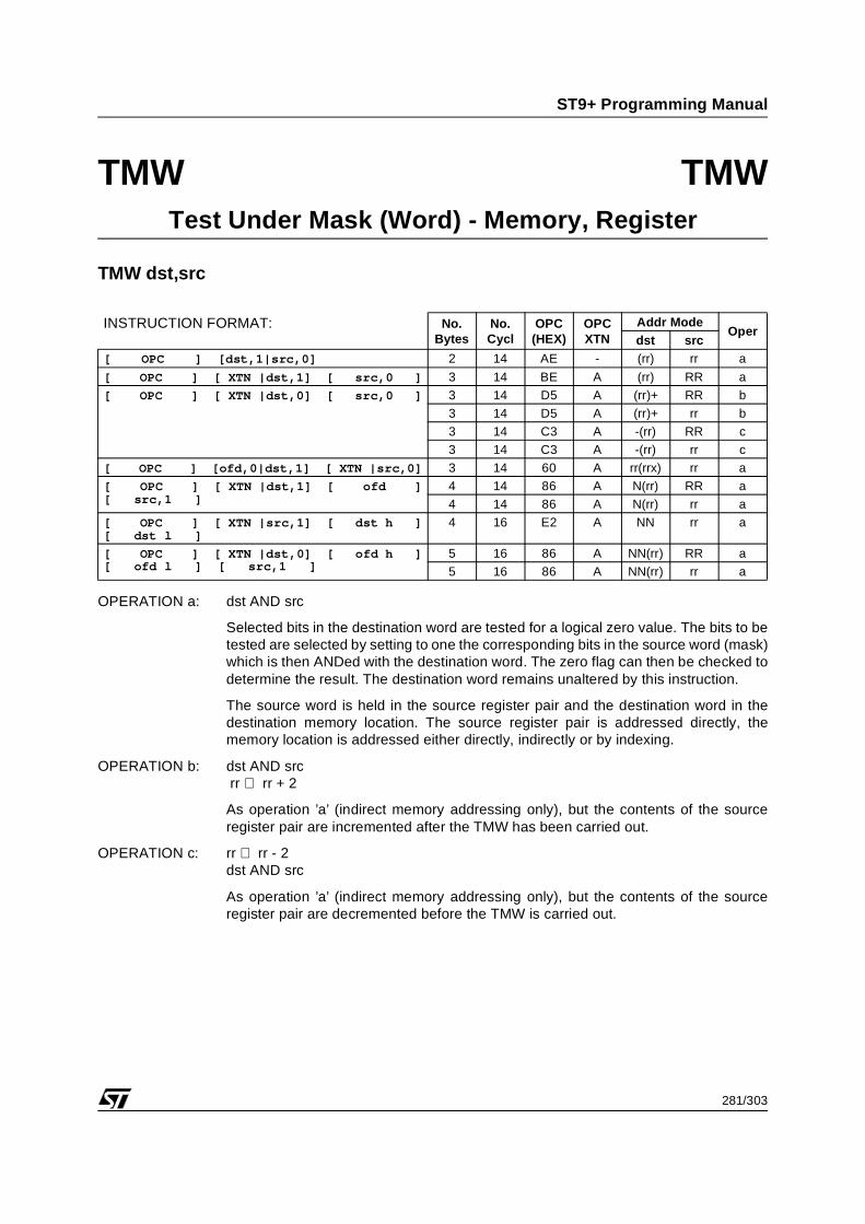
dst⇐dst AND srcdst⇐dst AND srcdst⇐dst AND srcdst⇐dst AND srcdst⇐dst AND srcdst⇐dst AND srcdst⇐dst AND srcdst⇐dst AND srcdst⇐dst AND srcdst⇐dst AND srcdst⇐dst AND srcdst⇐dst AND srcdst⇐dst AND srcdst⇐dst AND srcdst⇐dst AND srcrr⇐rr+1dst⇐dst AND srcrr⇐rr+1rr⇐rr-1dst⇐dst AND srcrr⇐rr-1dst⇐dst AND srcdst⇐dst AND srcdst⇐dst AND srcdst⇐dst AND srcdst⇐dst AND srcdst⇐dst AND srcrr⇐rr+1dst⇐dst AND srcrr⇐rr+1dst⇐dst AND srcdst⇐dst AND srcdst⇐dst AND srcdst⇐dst AND srcdst⇐dst AND srcdst⇐dst AND srcrr⇐rr-1dst⇐dst AND srcrr⇐rr-1dst⇐dst AND srcdst⇐dst AND srcdst⇐dst AND srcdst⇐dst AND srcdst⇐dst AND srcdst⇐dst AND srcdst⇐dst AND src
dst⇐dst AND srcdst⇐dst AND srcdst⇐dst AND srcdst⇐dst AND srcdst⇐dst AND srcdst⇐dst AND srcdst⇐dst AND srcdst⇐dst AND srcdst⇐dst AND srcdst⇐dst AND srcdst⇐dst AND srcdst⇐dst AND srcdst⇐dst AND srcdst⇐dst AND srcdst⇐dst AND srcrr⇐rr+2dst⇐dst AND srcrr⇐rr+2rr⇐rr-2dst⇐dst AND srcrr⇐rr-2dst⇐dst AND srcdst⇐dst AND srcdst⇐dst AND srcdst⇐dst AND srcdst⇐dst AND srcdst⇐dst AND srcrr⇐rr+2dst⇐dst AND srcrr⇐rr+2dst⇐dst AND srcdst⇐dst AND srcdst⇐dst AND srcdst⇐dst AND srcdst⇐dst AND srcdst⇐dst AND srcrr⇐rr-2dst⇐dst AND srcrr⇐rr-2dst⇐dst AND srcdst⇐dst AND srcdst⇐dst AND srcdst⇐dst AND srcdst⇐dst AND srcdst⇐dst AND srcdst⇐dst AND srcdst⇐dst AND src
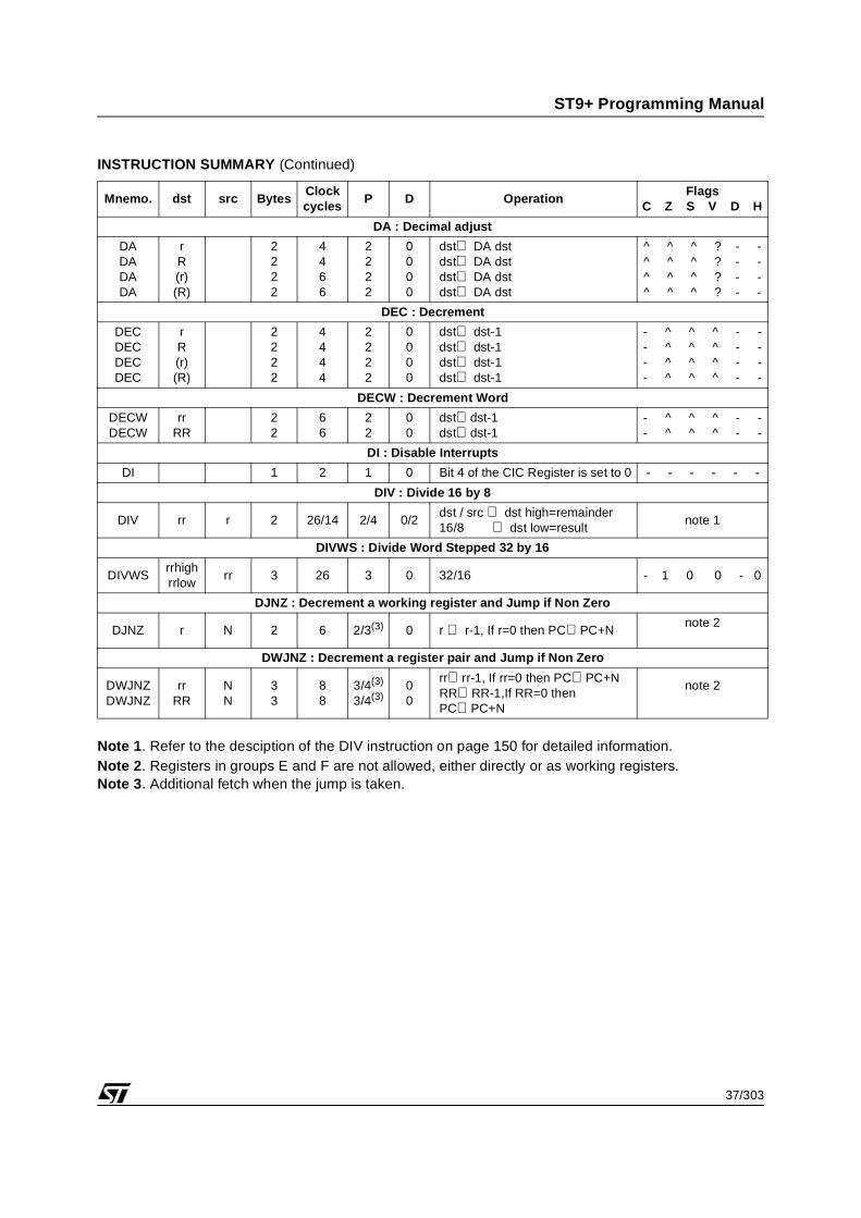
Note 1. Refer to the desciption of the DIV instruction on page 150 for detailed information.Note 2. Registers in groups E and F are not allowed, either directly or as working registers.Note 3. Additional fetch when the jump is taken.
Mnemo. dst src BytesClock cycles
P D OperationFlags
C Z S V D H
DA : Decimal adjust
DADADADA
rR(r)(R)
2222
4466
2222
0000
dst⇐ DA dstdst⇐ DA dstdst⇐ DA dstdst⇐ DA dst
^ ^ ^ ? - -^ ^ ^ ? - -^ ^ ^ ? - -^ ^ ^ ? - -
DEC : Decrement
DECDECDECDEC
rR(r)(R)
2222
4444
2222
0000
dst⇐ dst-1dst⇐ dst-1dst⇐ dst-1dst⇐ dst-1
- ^ ^ ^ - -- ^ ^ ^ - -- ^ ^ ^ - -- ^ ^ ^ - -
DECW : Decrement Word
DECWDECW
rrRR
22
66
22
00
dst⇐dst-1dst⇐dst-1
- ^ ^ ^ - -- ^ ^ ^ - -
DI : Disable Interrupts
DI 1 2 1 0 Bit 4 of the CIC Register is set to 0 - - - - - -
DIV : Divide 16 by 8
DIV rr r 2 26/14 2/4 0/2dst / src ⇐ dst high=remainder16/8 ⇐ dst low=result
note 1
DIVWS : Divide Word Stepped 32 by 16
DIVWSrrhighrrlow
rr 3 26 3 0 32/16 - 1 0 0 - 0
DJNZ : Decrement a working register and Jump if Non Zero
DJNZ r N 2 6 2/3(3) 0 r ⇐ r-1, If r=0 then PC⇐PC+Nnote 2
DWJNZ : Decrement a register pair and Jump if Non Zero
DWJNZDWJNZ
rrRR
NN
33
88
3/4(3)
3/4(3)00
rr⇐rr-1, If rr=0 then PC⇐PC+NRR⇐RR-1,If RR=0 then PC⇐PC+N
note 2
38/303
ST9+ Programming Manual
INSTRUCTION SUMMARY (Continued)
Note 1. All flags are restored to original setting (before interrupt occured).Note 2. Performed only if register file is not used.Note 3. Additional fetch when the jump is taken.
Mnemo. dst src BytesClock cycles
P D OperationFlags
C Z S V D H
EI : Enable Interrupts
EI 1 2 1 0 Bit 4 of the CICR register is set to 1 - - - - - -
EXT : Sign extend
EXTEXT
rrRR
22
66
22
00
r(7)⇒r(n) n=8-15R(7)⇒R(n) n=8-15
- - - - - -- - - - - -
HALT : Halt Operation
HALT 2 inf. 2 0Stops all internal clocks until next system reset if not in Watchdog Mode
JPcc NN 3 6/8 3 0IF cc(condition code) is true, PC⇐dst
- - - - - -
JPS : Jump to a routine in another segment
JPS N,NN 3 10 4 0 CSR⇐N, PC⇐NN - - - - - -
JPS (r),(rr) 2 10 3 0 CSR⇐r, PC⇐rr - - - - - -
JPS (R),(rr)
2 10 3 0 CSR⇐R, PC⇐rr - - - - - -
JRcc : Conditional Relative Jump to a Routine
JRcc N 2 6 2/3(3) 0IF cc(condition code)is true,PC⇐PC+dst
- - - - - -
39/303
ST9+ Programming Manual
INSTRUCTION SUMMARY (Continued)
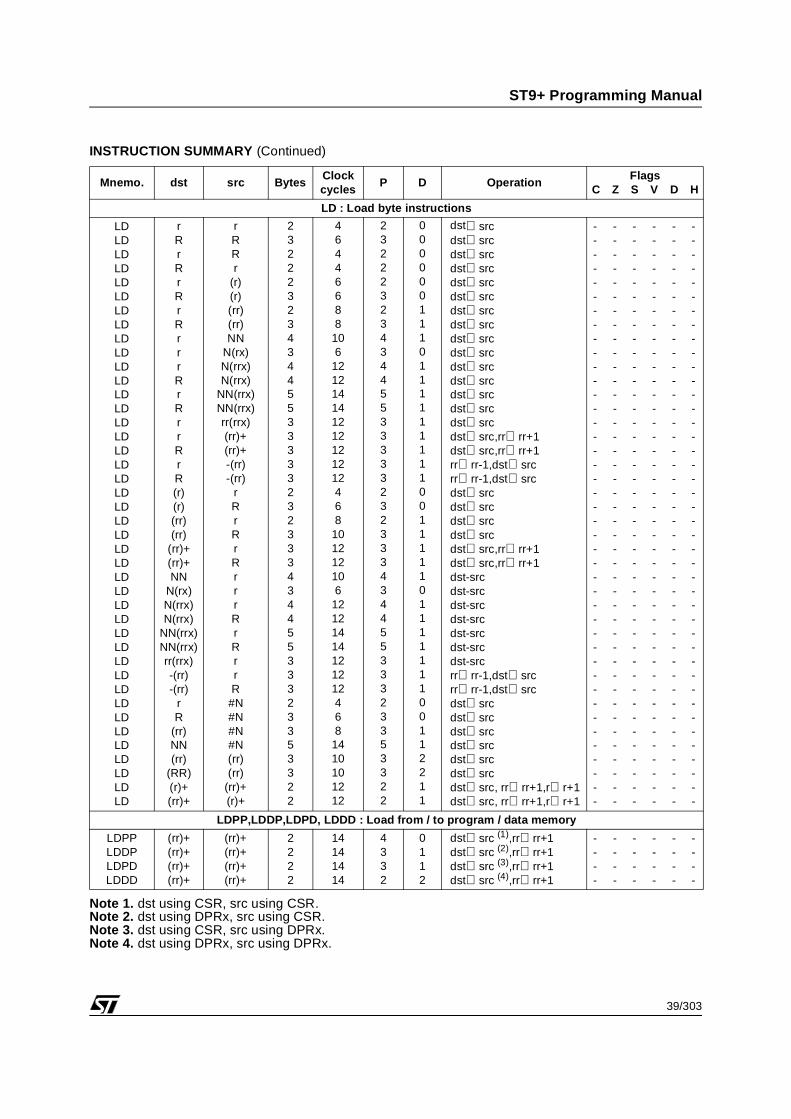
Note 1. dst using CSR, src using CSR. Note 2. dst using DPRx, src using CSR.Note 3. dst using CSR, src using DPRx. Note 4. dst using DPRx, src using DPRx.
Note 1. Refer to the description of the MUL instruction on page 182 for detailed information.Note 2. The value inside [ ] is valid for external memory stack
dst⇐dst OR srcdst⇐dst OR srcdst⇐dst OR srcdst⇐dst OR srcdst⇐dst OR srcdst⇐dst OR srcdst⇐dst OR srcdst⇐dst OR srcdst⇐dst OR srcdst⇐dst OR srcdst⇐dst OR srcdst⇐dst OR srcdst⇐dst OR srcdst⇐dst OR srcdst⇐dst OR src, rr⇐rr+1dst⇐dst OR src, rr⇐rr+1rr⇐rr-1, dst⇐dst OR srcrr⇐rr-1, dst⇐dst OR srcdst⇐dst OR srcdst⇐dst OR srcdst⇐dst OR srcdst⇐dst OR srcdst⇐dst OR src, rr⇐rr+1dst⇐dst OR src, rr⇐rr+1dst⇐dst OR srcdst⇐dst OR srcdst⇐dst OR srcdst⇐dst OR srcdst⇐dst OR srcdst⇐dst OR srcrr⇐rr-1, dst⇐dst OR srcrr⇐rr-1, dst⇐dst OR srcdst⇐dst OR srcdst⇐dst OR srcdst⇐dst OR srcdst⇐dst OR srcdst⇐dst OR srcdst⇐dst OR src
dst⇐dst OR srcdst⇐dst OR srcdst⇐dst OR srcdst⇐dst OR srcdst⇐dst OR srcdst⇐dst OR srcdst⇐dst OR srcdst⇐dst OR srcdst⇐dst OR srcdst⇐dst OR srcdst⇐dst OR srcdst⇐dst OR srcdst⇐dst OR srcdst⇐dst OR srcdst⇐dst OR srcrr⇐rr+2dst⇐dst OR srcrr⇐rr+2rr⇐rr-2dst⇐dst OR srcrr⇐rr-2dst⇐dst OR srcdst⇐dst OR srcdst⇐dst OR srcdst⇐dst OR srcdst⇐dst OR srcdst⇐dst OR srcrr⇐rr+2dst⇐dst OR srcrr⇐rr+2dst⇐dst OR srcdst⇐dst OR srcdst⇐dst OR srcdst⇐dst OR srcdst⇐dst OR srcdst⇐dst OR srcrr⇐rr-2dst⇐dst OR srcrr⇐rr-2dst⇐dst OR srcdst⇐dst OR srcdst⇐dst OR srcdst⇐dst OR srcdst⇐dst OR srcdst⇐dst OR srcdst⇐dst OR srcdst⇐dst OR src
Note 1. Following this instruction, all addressing modes referring to address spaces will use DPRx registers.Note 2. Following this instruction, all addressing modes referring to address spaces will use CSR register,
except for the following instructions which operate with DPRx registers independently of the set-ting of the DP flag :CALLS, RETS, LINK/LINKU, UNLINK/UNLINKU, PUSH(W)/PUSHU(W),POP(W)/POPU(W), PEA/PEAU, and CALL, RET, IRET and interrupt execution (assuming theStack Pointers are not pointing to the Register File).
NOT dst AND srcNOT dst AND srcNOT dst AND srcNOT dst AND srcNOT dst AND srcNOT dst AND srcNOT dst AND srcNOT dst AND srcNOT dst AND srcNOT dst AND srcNOT dst AND srcNOT dst AND srcNOT dst AND srcNOT dst AND srcNOT dst AND srcrr⇐rr+1NOT dst AND srcrr⇐rr+1rr⇐rr-1NOT dst AND srcrr⇐rr-1NOT dst AND srcNOT dst AND srcNOT dst AND srcNOT dst AND srcNOT dst AND srcNOT dst AND srcrr⇐rr+1dst⇐dst AND srcrr⇐rr+1NOT dst AND srcNOT dst AND srcNOT dst AND srcNOT dst AND srcNOT dst AND srcNOT dst AND srcrr⇐rr-1 NOT dst AND srcrr⇐rr-1 NOT dst AND srcNOT dst AND srcNOT dst AND srcNOT dst AND srcNOT dst AND srcNOT dst AND srcNOT dst AND src
NOT dst AND srcNOT dst AND srcNOT dst AND srcNOT dst AND srcNOT dst AND srcNOT dst AND srcNOT dst AND srcNOT dst AND srcNOT dst AND srcNOT dst AND srcNOT dst AND srcNOT dst AND srcNOT dst AND srcNOT dst AND srcNOT dst AND srcrr⇐rr+2NOT dst AND srcrr⇐rr+2rr⇐rr-2NOT dst AND srcrr⇐rr-2NOT dst AND srcNOT dst AND srcNOT dst AND srcNOT dst AND srcNOT dst AND srcNOT dst AND srcrr⇐rr+2NOT dst AND srcrr⇐rr+2NOT dst AND srcNOT dst AND srcNOT dst AND srcNOT dst AND srcNOT dst AND srcNOT dst AND srcrr⇐rr-2NOT dst AND srcrr⇐rr-2NOT dst AND srcNOT dst AND srcNOT dst AND srcNOT dst AND srcNOT dst AND srcNOT dst AND srcNOT dst AND srcNOT dst AND src
dst AND srcdst AND srcdst AND srcdst AND srcdst AND srcdst AND srcdst AND srcdst AND srcdst AND srcdst AND srcdst AND srcdst AND srcdst AND srcdst AND srcdst AND srcrr⇐rr+1dst AND -srcrr⇐rr+1rr⇐rr-1dst AND srcrr⇐rr-1dst AND srcdst AND srcdst AND srcdst AND srcdst AND srcdst AND srcrr⇐rr+1dst AND srcrr⇐rr+1dst AND srcdst AND srcdst AND srcdst AND srcdst AND srcdst AND srcrr⇐rr-1dst AND srcrr⇐rr-1dst AND srcdst AND srcdst AND srcdst AND srcdst AND srcdst AND srcdst AND src
dst AND srcdst AND srcdst AND srcdst AND srcdst AND srcdst AND srcdst AND srcdst AND srcdst AND srcdst AND srcdst AND srcdst AND srcdst AND srcdst AND srcdst AND srcrr⇐rr+2dst AND srcrr⇐rr+2rr⇐rr-2dst AND srcrr⇐rr-2dst AND srcdst AND srcdst AND srcdst AND srcdst AND srcdst AND srcrr⇐rr+2dst AND srcrr⇐rr+2dst AND srcdst AND srcdst AND srcdst AND srcdst AND srcdst AND srcrr⇐rr-2dst AND srcrr⇐⇐rr-2dst AND srcdst AND srcdst AND srcdst AND srcdst AND srcdst AND srcdst AND srcdst AND src
2 OPCODE MAPFor the following symbols, suffix d means destination and suffix s means source.
R, Rd, Rs: general registers (8 bits), if the 4 Most Significant Bits (MSB) are Dh then the 4 Least Signifi-cant Bits (LSB) specify a working register.
rr,rrd,rrs: working register pair (3 bits), a single bit (0 or 1) follows.
RR,RRd,RRs: general register pair (7 bits), if the 4 Most Significant Bits (MSB) are Dh then the 3 LeastSignificant Bits (LSB) specify a working register; a single bit (0 or 1) follows.
bd,bs: destination and source bit numbers (3 bits followed by a 0 or 1), associated with rd and rs for r.bbit addressing modes.
wwwww: 5-bit register window number (for SRP...) pppppp: 6-bit register page number (for SPP).
K: ALU parametrization, 4 bits (corresponding instruction is ALD or ALDW, value of K gives instruction tobe substituted for "ALD":
Table 15. Opcode Map
K= 0 1 2 3 4 5 6 8 9 A F
ALD= OR AND SBC ADC ADD SUB XOR CP CP TM LD
OPCODE BYTE1 BYTE2 BYTE3 BYTE4 BYTE5OPCODE
MNEMONICADDRESSING
MODE 00 EI
01 SCF
02 rd,rs OR rd,rs
03 rd,rs OR rd,(rs)
04 Rs Rd OR Rd,Rs
05 Rd N OR Rd,#N
06 K,rr1 Nd Nhs Nls ALDW Nd(rr),#NNs
06 K,rr0 Nhd Nld Nhs Nls ALDW NNd(rr),#NNs
07 RRs0 RRd0 ORW RRd,RRs
07 RRd1 Nhs Nls ORW RRd,#NN
08 Rs LD r0,Rs
09 Rd LD Rd,r0
0A N DJNZ r0,N
0B N JR F,N
0C N LD r0,#N
0D Nh Nl JP F,NN
0E rrd0,rrs0 ORW rrd,rrs
0E rrd1,rrs0 ORW (rrd),rrs
0E rrd0,rrs1 ORW rrd,(rrs)
0E rrd1,rrs1 ORW (rrd),(rrs)
0F bd1,rd bs0,rs BOR rd.b,rs.b
0F bd1,rd bs1,rs BOR rd.b,!rs.b
0F bd0,rd BSET rd.b
10 DI
11 RCF
12 rd,rs AND rd,rs
13 rd,rs AND rd,(rs)
14 Rs Rd AND Rd,Rs
60/303
ST9+ Programming Manual
15 Rd N AND Rd,#N
16 Rs Rd XCH Rs,Rd
17 RRs0 RRd0 ANDW RRd,RRs
17 RRd1 Nhs Nls ANDW RRd,#NN
18 Rs LD r1,Rs
19 Rd LD Rd,r1
1A N DJNZ r1,N
1B N JR LT,N
1C N LD r1,#N
1D Nh Nl JP LT,NN
1E rrd0,rrs0 ANDW rrd,rrs
1E rrd1,rrs0 ANDW (rrd),rrs
1E rrd0,rrs1 ANDW rrd,(rrs)
1E rrd1,rrs1 ANDW (rrd),(rrs)
1F bd1,rd bs0,rs BAND rd.b,rs.b
1F bd1,rd bs1,rs BAND rd.b,rs.b
1F bd0,rd BRES rd.b
20 Rd POPU Rd
21 Rd POPU (Rd)
22 rd,rs SBC rd,rs
23 rd,rs SBC rd,(rs)
24 Rs Rd SBC Rd,Rs
25 Rd N SBC Rd,#N
26 K,rr1 N R ALD N(rr),R
26 K,rr0 N N R ALD NN(rr),R
27 RRs0 RRd0 SBCW RRd,RRs
27 RRd1 Nhs Nls SBCW RRd,#NN
28 Rs LD r2,Rs
29 Rd LD Rd,r2
2A N DJNZ r2,N
2B N JR LE,N
2C N LD r2,#N
2D Nh Nl JP LE,NN
2E rrd0,rrs0 SBCW rrd,rrs
2E rrd1,rrs0 SBCW (rrd),rrs
2E rrd0,rrs1 SBCW rrd,(rrs)
2E rrd1,rrs1 SBCW (rrd),(rrs)
2F RR0 SRAW RR
2F K,0001 Ns Ndh Ndl ALD NNd,#Ns
30 Rd PUSHU Rd
31 Rd PUSHU (Rd)
32 rd,rs ADC rd,rs
33 rd,rs ADC rd,(rs)
34 Rs Rd ADC Rd,Rs
35 Rd N ADC Rd,#N
36 RR0 RRCW RR
36 K,0001 Nsh Nsl Ndh Ndl ALDW NNd,#NNs
OPCODE BYTE1 BYTE2 BYTE3 BYTE4 BYTE5OPCODE
MNEMONICADDRESSING
MODE
61/303
ST9+ Programming Manual
37 RRs0 RRd0 ADCW RRd,RRs
37 RRd1 Nhs Nls ADCW RRd,#NN
38 Rs LD r3,Rs
39 Rd LD Rd,r3
3A N DJNZ r3,N
3B N JR ULE,N
3C N LD r3,#N
3D Nh Nl JP ULE,NN
3E rrd0,rrs0 ADCW rrd,rrs
3E rrd1,rrs0 ADCW (rrd),rrs
3E rrd0,rrs1 ADCW rrd,(rrs)
3E rrd1,rrs1 ADCW (rrd),(rrs)
3F 01nnnnnn Nh Nl CALLS nnnnnn,NN
3F 11nnnnnn Nh Nl JPS nnnnnn,NN
40 Rd DEC Rd
41 Rd DEC (Rd)
42 rd,rs ADD rd,rs
43 rd,rs ADD rd,(rs)
44 Rs Rd ADD Rd,Rs
45 Rd N ADD Rd,#N
46 RET
47 RRs0 RRd0 ADDW RRd,RRs
47 RRd1 Nhs Nls ADDW RRd,#NN
48 Rs LD r4,Rs
49 Rd LD Rd,r4
4A N DJNZ r4,N
4B N JR OV,N
4C N LD r4,#N
4D Nh Nl JP OV,NN
4E rrd0,rrs0 ADDW rrd,rrs
4E rrd1,rrs0 ADDW (rrd),rrs
4E rrd0,rrs1 ADDW rrd,(rrs)
4E rrd1,rrs1 ADDW (rrd),(rrs)
4F rrd0,rs MUL rrd,rs
50 Rd INC Rd
51 Rd INC (Rd)
52 rd,rs SUB rd,rs
53 rd,rs SUB rd,(rs)
54 Rs Rd SUB Rd,Rs
55 Rd N SUB Rd,#N
56 RRs0 rrh0,rrl0 DIVWS rrh,rrl,RRs
57 RRs0 RRd0 SUBW RRd,RRs
57 RRd1 Nhs Nls SUBW RRd,#NN
58 Rs LD r5,Rs
59 Rd LD Rd,r5
5A N DJNZ r5,N
5B N JR MI,N
OPCODE BYTE1 BYTE2 BYTE3 BYTE4 BYTE5OPCODE
MNEMONICADDRESSING
MODE
62/303
ST9+ Programming Manual
5C N LD r5,#N
5D Nh Nl JP MI,NN
5E rrd0,rrs0 SUBW rrd,rrs
5E rrd1,rrs0 SUBW (rrd),rrs
5E rrd0,rrs1 SUBW rrd,(rrs)
5E rrd1,rrs1 SUBW (rrd),(rrs)
5F rrd0,rs DIV rrd,rs
60 rrs1,rrx0 K,rd ALD rd,rrs(rrx)
60 rrd1,rrx1 K,rs ALD rrd(rrx),rs
60 rrs0,rrx0 K,rrde ALDW rrd,rrs(rrx)
60 rrd0,rrx1 K,rrse ALDW rrd(rrx),rrs
61 CCF
62 rd,rs XOR rd,rs
63 rd,rs XOR rd,(rs)
64 Rs Rd XOR Rd,Rs
65 Rd N XOR Rd,#N
66 Rs PUSH Rs
67 RRs0 RRd0 XORW RRd,RRs
67 RRd1 Nhs Nls XORW RRd,#NN
68 Rs LD r6,Rs
69 Rd LD Rd,r6
6A N DJNZ r6,N
6B N JR EQ,N
6C N LD r6,#N
6D Nh Nl JP EQ,NN
6E rrd0,rrs0 XORW rrd,rrs
6E rrd1,rrs0 XORW (rrd),rrs
6E rrd0,rrs1 XORW rrd,(rrs)
6E rrd1,rrs1 XORW (rrd),(rrs)
6F bd1,rd bs0,rs BXOR rd.bd,rs.bs
6F bd1,rd bs1,rs BXOR rd.bd, rs.bs
6F bd0,rd BCPL rd.bd
70 Rd DA Rd
71 Rd DA (Rd)
72 K,rrs1 Rd ALD Rd,(rrs)
72 K,rrd0 Rs ALD (rrd),Rs
73 K,rrs0 RRd0 ALD (RRd),(rrs)
73 0100,rr1 R CALLS (R),(rr)
73 1100,rr1 R JPS (R),(rr)
74 RRd1 CALL (RRd)
74 RRs0 PUSHW RRs
75 RRd0 POPW RRd
75 RRd1 UNLINK RRd
76 Rd POP Rd
77 Rd POP (Rd)
78 Rs LD r7,Rs
79 Rd LD Rd,r7
OPCODE BYTE1 BYTE2 BYTE3 BYTE4 BYTE5OPCODE
MNEMONICADDRESSING
MODE
63/303
ST9+ Programming Manual
7A N DJNZ r7,N
7B N JR UL,N
7C N LD r7,#N
7D Nh Nl JP UL,NN
7E K,rrs0 RRd0 ALDW RRd,(rrs)
7F K,rrx1 N Rd ALD Rd,N(rrx)
7F K,rrx0 Nh Nl Rd ALD Rd,NN(rrx)
80 Rd CPL Rd
81 Rd CPL (Rd)
82 rd,rs CP rd,rs
83 rd,rs CP rd,(rs)
84 Rs Rd CP Rd,Rs
85 Rd N CP Rd,#N
86 K,rrx1 N RRs1 ALDW N(rrx),RRs
86 K,rrx1 N RRd0 ALDW RRd,N(rrx)
86 K,rrx0 Nh Nl RRs1 ALDW NN(rrx),RRs
86 K,rrx0 Nh Nl RRd0 ALDW RRd,NN(rrx)
87 RRs0 RRd0 CPW RRd,RRs
87 RRd1 Nhs Nls CPW RRd,#NN
88 Rs LD r8,Rs
89 Rd LD Rd,r8
8A N DJNZ r8,N
8B N JR T,N
8C N LD r8,#N
8D Nh Nl JP T,NN
8E rrd0,rrs0 CPW rrd,rrs
8E rrd1,rrs0 CPW (rrd),rrs
8E rrd0,rrs1 CPW rrd,(rrs)
8E rrd1,rrs1 CPW (rrd),(rrs)
8F RRd0 RLCW RRd
8F F1 N PUSH N
8F F3 N PUSHU N
8F C1 Nh Nl PUSH NN
8F C3 Nh Nl PUSHU NN
8F 01 RRx0 N PEA N(RRx)
8F 01 RRx1 Nl Nh PEA NN(RRx)
8F 03 RRx0 N PEAU N(RRx)
8F 03 RRx1 Nl Nh PEAU NN(RRx)
90 Rd CLR Rd
91 Rd CLR (Rd)
92 rd,rs CP rd,rs
93 rd,rs CP rd,(rs)
94 Rs Rd CP Rd,Rs
95 Rd N CP Rd,#N
96 RRs0 K,rd ALDW (rd),RRs
97 RRs0 RRd0 CPW RRd,RRs
97 RRd1 Nhs Nls CPW RRd,#NN
OPCODE BYTE1 BYTE2 BYTE3 BYTE4 BYTE5OPCODE
MNEMONICADDRESSING
MODE
64/303
ST9+ Programming Manual
98 Rs LD r9,Rs
99 Rd LD Rd,r9
9A N DJNZ r9,N
9B N JR GE,N
9C N LD r9,#N
9D Nh Nl JP GE,NN
9E rrd0,rrs0 CPW rrd,rrs
9E rrd1,rrs0 CPW (rrd),rrs
9E rrd0,rrs1 CPW rrd,(rrs)
9E rrd1,rrs1 CPW (rrd),(rrs)
9F rrs0,rd N CPJF rd,(rrs),N
9F rrs1,rd N CPJT rd,(rrs),N
A0 Rd ROL Rd
A1 Rd ROL (Rd)
A2 rd,rs TM rd,rs
A3 rd,rs TM rd,(rs)
A4 Rs Rd TM Rd,Rs
A5 Rd N TM Rd,#N
A6 K,rs RRd0 ALDW RRd,(rs)
A7 RRs0 RRd0 TMW RRd,RRs
A7 RRd1 Nhs Nls TMW RRd,#NN
A8 Rs LD r10,Rs
A9 Rd LD Rd,r10
AA N DJNZ r10,N
AB N JR GT,N
AC N LD r10,#N
AD Nh Nl JP GT,NN
AE rrd0,rrs0 TMW rrd,rrs
AE rrd1,rrs0 TMW (rrd),rrs
AE rrd0,rrs1 TMW rrd,(rrs)
AE rrd1,rrs1 TMW (rrd),(rrs)
AF b0,rd N BTJT b.rd,N
AF b1,rd N BTJF b.rd,N
B0 Rd RLC Rd
B1 Rd RLC (Rd)
B2 rs,rx N LD N(rx),rs
B3 rd,rx N LD rd,N(rx)
B4 K,rrs1 Rd ALD Rd,(rrs)+
B4 K,rrd0 Rs ALD (rrd)+,Rs
B5 rd,rrs0 LD rd,(rrs)
B5 rs,rrd1 LD (rrd),rs
B6 RR0 PUSHUW RR
B6 RR1 N LINKU RR,#N
B7 RR0 POPUW RR
B7 RR1 UNLINKU RR
B8 Rs LD r11,Rs
B9 Rd LD Rd,r11
OPCODE BYTE1 BYTE2 BYTE3 BYTE4 BYTE5OPCODE
MNEMONICADDRESSING
MODE
65/303
ST9+ Programming Manual
BA N DJNZ r11,N
BB N JR UGT,N
BC N LD r11,#N
BD Nh Nl JP UGT,NN
BE K,rrd1 RRs0 ALDW (rr),RR
BE K,rrd0 Nh Nl ALDW (rr),#NN
BF RRd0 Nh Nl LDW RRd,#NN
BF 01 HALT
C0 Rd ROR Rd
C1 Rd ROR (Rd)
C2 K,rrs1 Rd ALD Rd,-(rrs)
C2 K,rrd0 Rs ALD -(rrd),Rs
C3 K,rrs1 RRd ALDW
C3 K,rrd0 RRs ALDW RRd,-(rrs)
C4 K,rd Nh Nl ALD -(rrd),RRs
C5 K,rs Nh Nl ALD NN,rs
C6 RR0 N DWJNZ RR,N
C6 RR1 EXT RR
C7 wwwww000 SRP wwwww
C7 wwwww100 SRP0 wwwww
C7 wwwww101 SRP1 wwwww
C7 pppppp10 SPP pppppp
C8 Rs LD r12,Rs
C9 Rd LD Rd,r12
CA N DJNZ r12,N
CB N JR NOV,N
CC N LD r12,#N
CD Nh Nl JP NOV,NN
CE ETRAP
CF RRd0 DECW RRd
D0 Rd RRC Rd
D1 Rd RRC (Rd)
D2 Nh Nl CALL NN
D3 IRET
D4 RR0 JP (RR)
D4 RR1 N LINK RR,#N
D5 K,rrs1 RRd0 ALDW RRd,(rrd)+
D5 K,rrd0 RRs0 ALDW (rrd)+,RRs
D6 rrd0,rrs0 LDPP (rrd)+,(rrs)+
D6 rrd1,rrs0 LDDP (rrd)+,(rrs)+
D6 rrd0,rrs1 LDPD (rrd)+,(rrs)+
D6 rrd1,rrs1 LDDD (rrd)+,(rrs)+
D7 rd,rrs1 LD (rd)+,(rrs)+
D7 rs,rrd0 LD (rrd)+,(rs)+
D8 Rs LD r13,Rs
D9 Rd LD Rd,r13
DA N DJNZ r13,N
OPCODE BYTE1 BYTE2 BYTE3 BYTE4 BYTE5OPCODE
MNEMONICADDRESSING
MODE
66/303
ST9+ Programming Manual
DB N JR PL,N
DC N LD r13,#N
DD Nh Nl JP PL,NN
DE rrs1,rx N LDW N(rx),rrs
DE rrd0,rx N LDW rrd,N(rx)
DF RRd0 INCW RRd
E0 Rd SRA Rd
E1 Rd SRA (Rd)
E2 K,rrd0 Nh Nl ALDW rrd,NN
E2 K,rrs1 Nh Nl ALDW NN,rrs
E3 rrd0,rrs0 LDW rrd,rrs
E3 rrd1,rrs0 LDW (rrd),rrs
E3 rrd0,rrs1 LDW rrd,(rrs)
E3 rrd1,rrs1 LDW (rrd),(rrs)
E4 rd,rs LD rd,(rs)
E5 rd,rs LD (rd),rs
E6 Rs K,rd ALD (rd),Rs
E7 K,rs Rd ALD Rd,(rs)
E8 Rs LD r14,Rs
E9 Rd LD Rd,r14
EA N DJNZ r14,N
EB N JR NE,N
EC N LD r14,#N
ED Nh Nl JP NE,NN
EE SPM
EF RRs0 RRd0 LDW RRd,RRs
EF 01 WFI
EF 31 ERET
F0 Rd SWAP Rd
F1 Rd SWAP (Rd)
F2 bs1,rs bd0,rd BLD rd.bd,rs.bs
F2 bs1,rs bd1,rd BLD rd.bd,rs.bs
F2 bd0,rd BTSET rd.bd
F3 K,rrd0 N ALD (rrd),#N
F4 Rs Rd LD Rd,Rs
F5 Rd N LD Rd,#N
F6 bd0,rr0 BTSET (rr).bd
F6 01 RETS
F7 Rs PUSH (Rs)
F8 Rs LD r15,Rs
F9 Rd LD Rd,r15
FA N DJNZ r15,N
FB N JR NC,N
FC N LD r15,#N
FD Nh Nl JP NC,NN
FE SDM
FF NOP
OPCODE BYTE1 BYTE2 BYTE3 BYTE4 BYTE5OPCODE
MNEMONICADDRESSING
MODE
INSTRUCTIONS
68/303
ST9+ Programming Manual
INTRODUCTION
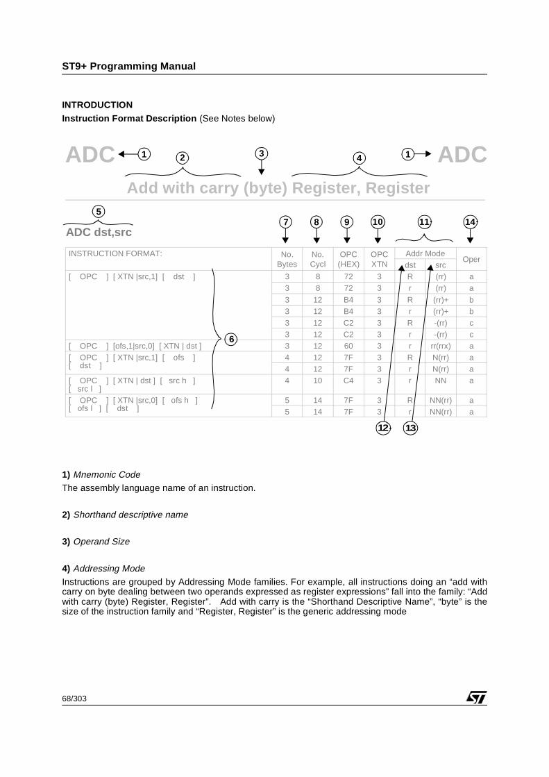
Instruction Format Description (See Notes below)
1) Mnemonic CodeThe assembly language name of an instruction.
2) Shorthand descriptive name
3) Operand Size
4) Addressing ModeInstructions are grouped by Addressing Mode families. For example, all instructions doing an “add withcarry on byte dealing between two operands expressed as register expressions” fall into the family: “Addwith carry (byte) Register, Register”. Add with carry is the “Shorthand Descriptive Name”, “byte” is thesize of the instruction family and “Register, Register” is the generic addressing mode
Add with carry (byte) Register, Register
INSTRUCTION FORMAT: No.Bytes
No.Cycl
OPC(HEX)
OPCXTN
Addr ModeOper
dst src
[ OPC ] [ XTN |src,1] [ dst ] 3 8 72 3 R (rr) a
3 8 72 3 r (rr) a
3 12 B4 3 R (rr)+ b
3 12 B4 3 r (rr)+ b
3 12 C2 3 R -(rr) c
3 12 C2 3 r -(rr) c
[ OPC ] [ofs,1|src,0] [ XTN | dst ] 3 12 60 3 r rr(rrx) a
[ OPC ] [ XTN |src,1] [ ofs ][ dst ]
4 12 7F 3 R N(rr) a
4 12 7F 3 r N(rr) a
[ OPC ] [ XTN | dst ] [ src h ][ src l ]
4 10 C4 3 r NN a
[ OPC ] [ XTN |src,0] [ ofs h ][ ofs l ] [ dst ]
5 14 7F 3 R NN(rr) a
5 14 7F 3 r NN(rr) a
1 2 143
5
6
10
1312
117 8 9ADC dst,src
14
ADCADC
1
69/303
ST9+ Programming Manual
INTRODUCTION (Cont’d)
5) Assembly syntax
The assembly syntax gives the general form of the instruction, e.g.ADC dst, srchas to be interpreted with all pairs of destination (dst) and source (src) operands as available in the cor-responding columns of the instruction table.
6) Encoding patterns Within a given instruction family, several encoding patterns are possible, depending on which combinationof operands is involved in the instruction. The instruction table contains a line for each possible encodingpattern.
The nomenclature used in these encoding patterns is listed below:
[ a ] represents the byte whose value is a. In this case, value a is encoded on 8 bits.
[ a ] [ b ] represents the encoding of two consecutive bytes (the number of square brackets corre-sponds to the number of consecutive bytes).
[ a | b ] represents the byte obtained by concatenating tetrad a to tetrad b. In this case, values a andb are encoded on 4 bits. A tetrad is four bits and can also be called a nibble.
[ a | b,0 ] In this case, b is encoded on three bits and a 0 bit is added to complete the tetrad.
src h represents the high-order byte of a 16-bit immediate value, noted NN in the src column.
src l represents the low-order byte of a 16-bit immediate value, noted NN in the src column.
dst h represents the high-order byte of a 16-bit immediate value, noted NN in the dst column.
dst l represents the low-order byte of a 16-bit immediate value, noted NN in the dst column.
ofs represents either a single-byte immediate value offset, noted N in the src column, or the encod-ing of the first rr register in case of a source rr(rr) operand.
ofd represents either a single-byte immediate value offset, noted N in the dst column, or the encod-ing of the first rr register in case of a destination rr (rr) operand.
ofs h represents the high-order byte of a 16-bit immediate value, noted NN in the src column.
ofs l represents the low-order byte of a 16-bit immediate value, noted NN in the src column.
ofd h represents the high-order byte of a 16-bit immediate value, noted NN in the dst column.
ofd l represents the low-order byte of a 16-bit immediate value, noted NN in the dst column.
1
70/303
ST9+ Programming Manual
INTRODUCTION (Cont’d)
bts represents the encoding of bit number b of notation r.b in the source column.
btd represents the encoding of bit number b of notation r.b in the destination column.
cc represents the 4-bit encoding of the condition code, as described in Table 11 on page 23.
7) Number of bytes
The number of bytes needed to encode the full instruction.
8) Number of cycles
The number of cycles needed to perform the complete instruction.
9) Operation CodeAn 8-bit value expressed in hexadecimal notation.
10) Operation Code ExtensionAn opcode extension which can be encoded on 4 bits or on 8 bits, depending on the context.
11) Addressing Modes
R: a number between 0 and 255 representing a register encoded on 8 bits.
RR: an even number between 0 and 254 representing a pair of registers, encoded on 7 bits, as theregister number divided by 2.
r: a number between 0 and 15 representing a working register.
rr: an even number between 0 and 14 representing a pair of working registers, encoded on 3 bits asthe register number divided by 2.
r*: a special notation for [ 13 | r ].
rr*: a special notation for [ 13 | rr ].
12) DestinationThe encoding of the destination operand. It can be 3, 4 or 8 bits depending on the encoding context.
13) Source
The encoding of the source operand. It can be 3, 4 or 8 bits depending on the context.
14) Operation
A letter (a, b, etc.) which refers to a particular operation (OPERATION a, OPERATION b, etc.) describedbelow the table.
IMPORTANT: The use of the DPRx or CSR registers is required for all virtual memory addresses (16 bits)given in the following instruction examples. For simplicity in these examples, the virtual ad-dresses are equal to their physical addresses (22 bits) and the selection of the DPRx or CSRregisters is not taken into account, although this takes place in normal conditions.
1
71/303
ST9+ Programming Manual
ADC ADCAdd with carry (byte) Register, Register
ADC dst,src
OPERATION: dst ⇐ dst + src + C
The source byte, along with the carry flag, is added to the destination byte and theresult is stored in the destination byte. The source and destination byte can beaddressed either directly or indirectly.
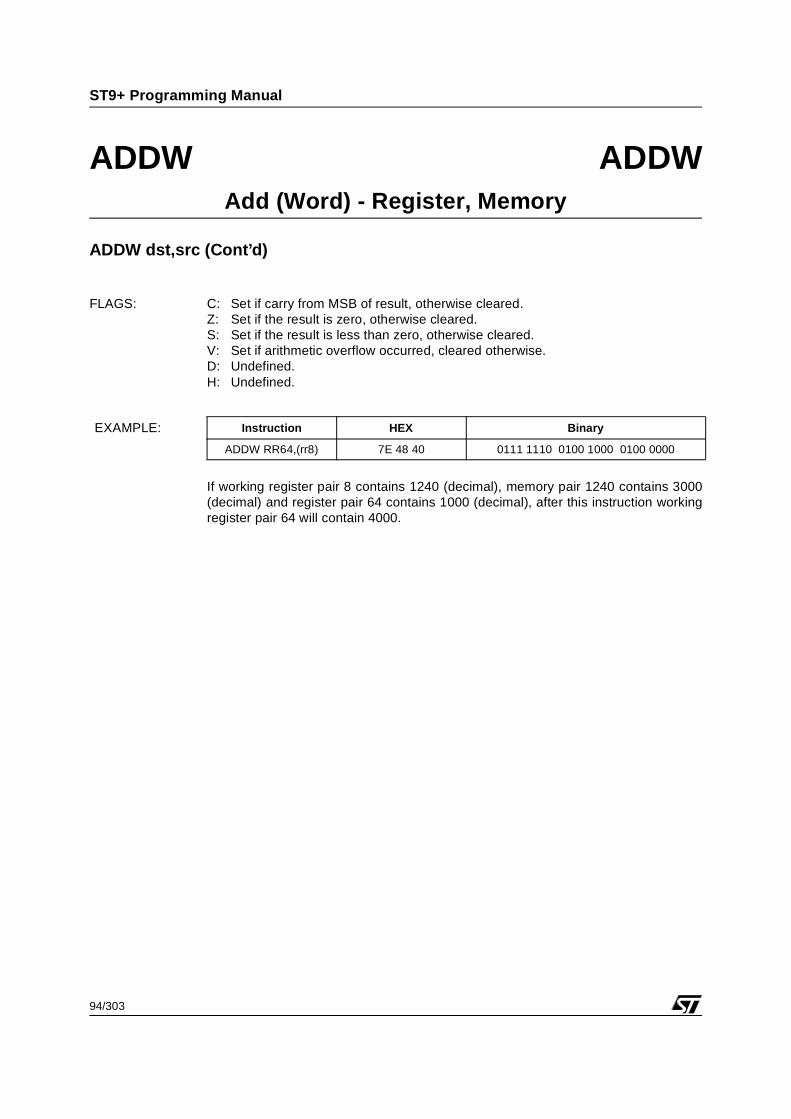
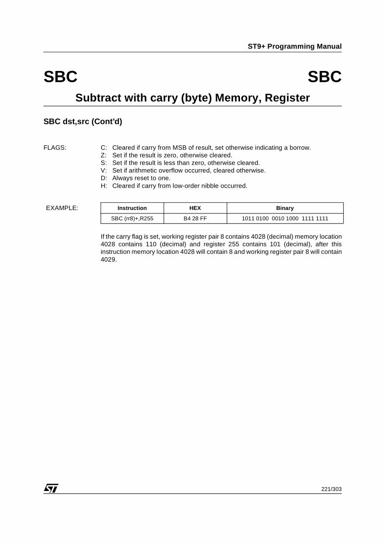
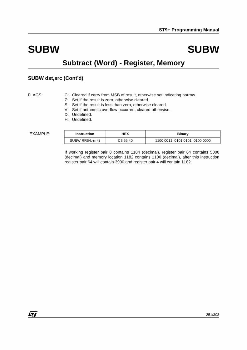
FLAGS: C: Set if carry from MSB of result, otherwise cleared.Z: Set if the result is zero, otherwise cleared.S: Set if the result is less than zero, otherwise cleared.V: Set if arithmetic overflow occurred, cleared otherwise.D: Always reset to zero.H: Set if carry from low-order nibble occurred.
If the carry flag is set, working register 8 contains 35 (decimal) and register 64contains 22 (decimal), after this instruction working register 8 will contain 58.
INSTRUCTION FORMAT: No.Bytes
No.Cycle
OPC(HEX)
OPCXTN
Addr Modedst src
[ OPC ] [ dst | src ] 2 4 32 - r r
2 6 33 - r (r)
[ OPC ] [ src ] [ dst ] 3 6 34 - R R
3 6 34 - r R
3 6 34 - R r
[ OPC ] [ src ] [ XTN | dst ] 3 6 E6 3 (r) R
3 6 E6 3 (r) r
[ OPC ] [ XTN | src ] [ dst ] 3 6 E7 3 R (r)
EXAMPLE: Instruction HEX Binary
ADC r8,R64 34 40 D8 0011 0100 0100 0000 1101 1000
1
72/303
ST9+ Programming Manual
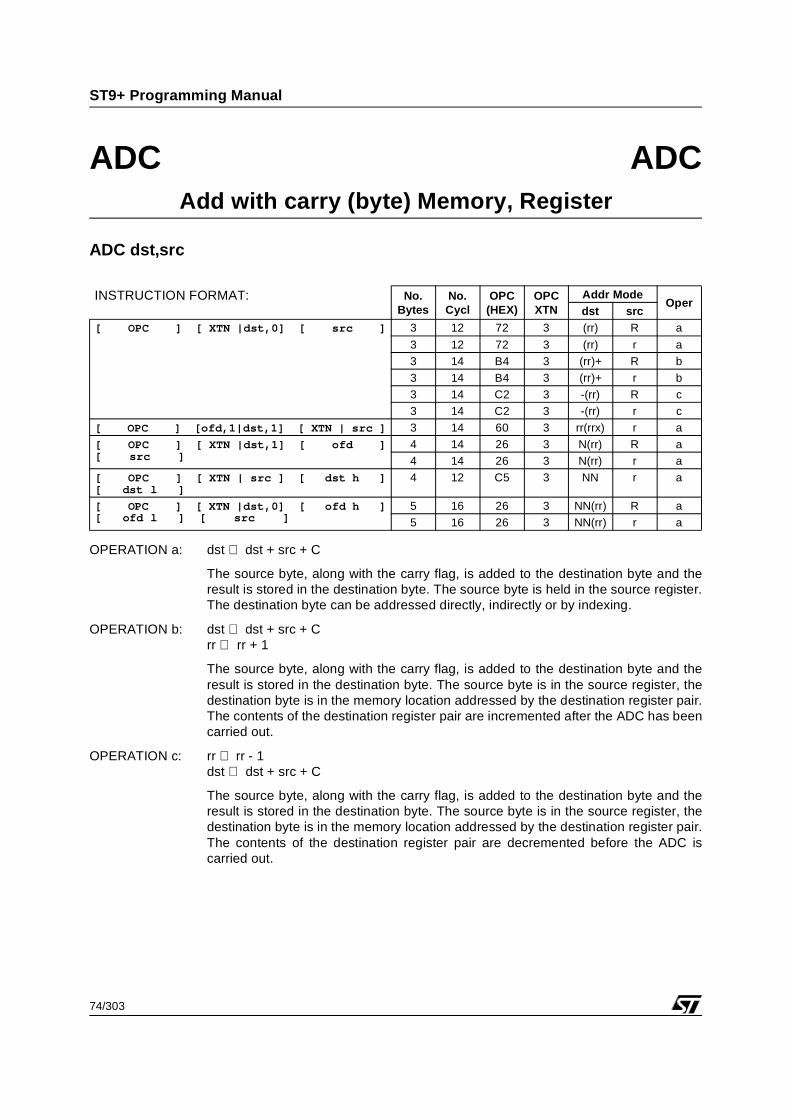
ADC ADCAdd with carry (byte) Register, Memory
ADC dst,src
OPERATION a: dst ⇐ dst + src + C
The source byte, along with the carry flag, is added to the destination byte and theresult is stored in the destination byte. The destination byte is held in the destinationregister. The source byte can be addressed directly, indirectly or by indexing.
OPERATION b: dst ⇐ dst + src + Crr ⇐ rr + 1
The source byte, along with the carry flag, is added to the destination byte and theresult is stored in the destination byte. The source byte is in the memory locationaddressed by the source register pair, the destination byte is in the destinationregister. The contents of the source register pair are incremented after the ADC hasbeen carried out.
OPERATION c: rr ⇐ rr - 1dst ⇔ dst + src + C
The source byte, along with the carry flag, is added to the destination byte and theresult is stored in the destination byte. The source byte is in the memory locationaddressed by the source register pair, the destination byte is in the destinationregister. The contents of the source register pair are decremented before the ADC iscarried out.
INSTRUCTION FORMAT: No.Bytes
No.Cycl
OPC(HEX)
OPCXTN
Addr ModeOper
dst src[ OPC ] [ XTN |src,1] [ dst ] 3 8 72 3 R (rr) a
3 8 72 3 r (rr) a
3 12 B4 3 R (rr)+ b
3 12 B4 3 r (rr)+ b
3 12 C2 3 R -(rr) c
3 12 C2 3 r -(rr) c
[ OPC ] [ofs,1|src,0] [ XTN | dst ] 3 12 60 3 r rr(rrx) a
[ OPC ] [ XTN |src,1] [ ofs ][ dst ]
4 12 7F 3 R N(rr) a
4 12 7F 3 r N(rr) a
[ OPC ] [ XTN | dst ] [ src h ][ src l ]
4 10 C4 3 r NN a
[ OPC ] [ XTN |src,0] [ ofs h ][ ofs l ] [ dst ]
5 14 7F 3 R NN(rr) a
5 14 7F 3 r NN(rr) a
1
73/303
ST9+ Programming Manual
ADC ADCAdd with carry (byte) Register, Memory
ADC dst,src (Cont’d)
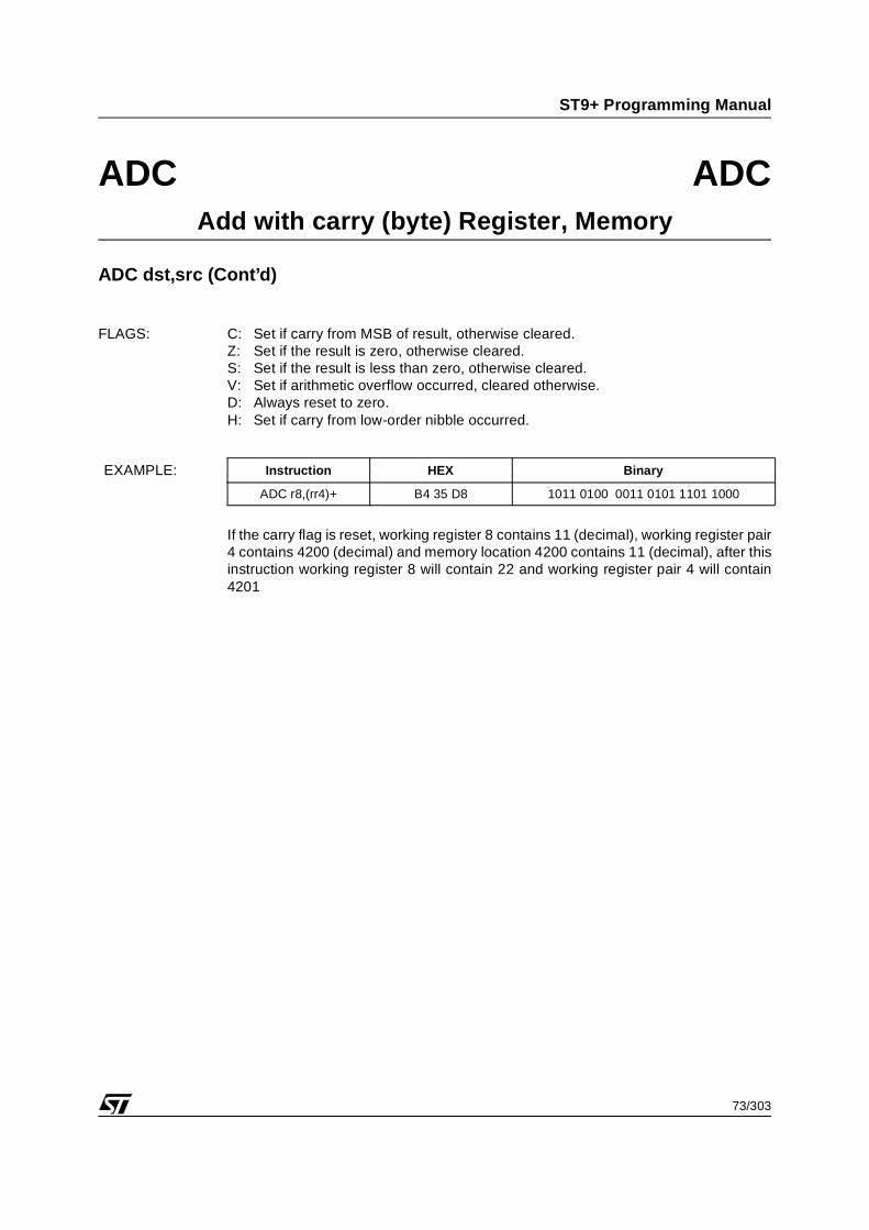
FLAGS: C: Set if carry from MSB of result, otherwise cleared.Z: Set if the result is zero, otherwise cleared.S: Set if the result is less than zero, otherwise cleared.V: Set if arithmetic overflow occurred, cleared otherwise.D: Always reset to zero.H: Set if carry from low-order nibble occurred.
If the carry flag is reset, working register 8 contains 11 (decimal), working register pair4 contains 4200 (decimal) and memory location 4200 contains 11 (decimal), after thisinstruction working register 8 will contain 22 and working register pair 4 will contain4201
The source byte, along with the carry flag, is added to the destination byte and theresult is stored in the destination byte. The source byte is held in the source register.The destination byte can be addressed directly, indirectly or by indexing.
OPERATION b: dst ⇐ dst + src + Crr ⇔ rr + 1
The source byte, along with the carry flag, is added to the destination byte and theresult is stored in the destination byte. The source byte is in the source register, thedestination byte is in the memory location addressed by the destination register pair.The contents of the destination register pair are incremented after the ADC has beencarried out.
OPERATION c: rr ⇐ rr - 1dst ⇔ dst + src + C
The source byte, along with the carry flag, is added to the destination byte and theresult is stored in the destination byte. The source byte is in the source register, thedestination byte is in the memory location addressed by the destination register pair.The contents of the destination register pair are decremented before the ADC iscarried out.
INSTRUCTION FORMAT: No.Bytes
No.Cycl
OPC(HEX)
OPCXTN
Addr ModeOper
dst src[ OPC ] [ XTN |dst,0] [ src ] 3 12 72 3 (rr) R a
3 12 72 3 (rr) r a
3 14 B4 3 (rr)+ R b
3 14 B4 3 (rr)+ r b
3 14 C2 3 -(rr) R c
3 14 C2 3 -(rr) r c
[ OPC ] [ofd,1|dst,1] [ XTN | src ] 3 14 60 3 rr(rrx) r a
[ OPC ] [ XTN |dst,1] [ ofd ][ src ]
4 14 26 3 N(rr) R a
4 14 26 3 N(rr) r a
[ OPC ] [ XTN | src ] [ dst h ][ dst l ]
4 12 C5 3 NN r a
[ OPC ] [ XTN |dst,0] [ ofd h ][ ofd l ] [ src ]
5 16 26 3 NN(rr) R a
5 16 26 3 NN(rr) r a
1
75/303
ST9+ Programming Manual
ADC ADCAdd with carry (byte) Memory, Register
ADC dst,src (Cont’d)
FLAGS: C: Set if carry from MSB of result, otherwise cleared.Z: Set if the result is zero, otherwise cleared.S: Set if the result is less than zero, otherwise cleared.V: Set if arithmetic overflow occurred, cleared otherwise.D: Always reset to zero.H: Set if carry from low-order nibble occurred.
.
If the carry flag is set, memory location 4028 contains 200 (decimal) and workingregister 8 contains 32 (decimal), after this instruction memory location 4028 willcontain 233.
The source byte, along with the carry flag, is added to the destination byte and theresult is stored in the destination byte. The source byte is in the memory locationaddressed by the source register pair, the destination byte is in the memory locationaddressed by the destination register pair.
FLAGS: C: Set if carry from MSB of result, otherwise cleared.Z: Set if the result is zero, otherwise cleared.S: Set if the result is less than zero, otherwise cleared.V: Set if arithmetic overflow occurred, cleared otherwise.D: Always reset to zero.H: Set if carry from low-order nibble occurred.
If the carry flag is set, working register pair 4 contains 2800 (decimal), memorylocation 2800 contains 46 (decimal), working register pair 8 contains 4200 (decimal)and memory location 4200 contains 45 (decimal), after this instruction memorylocation 2800 will contain 92.
The source byte, along with the carry flag, is added to the destination byte and theresult is stored in the destination byte. The source byte is the immediate value in theoperand, the destination byte can be in memory or in the register file.
FLAGS: C: Set if carry from MSB of result, otherwise cleared.Z: Set if the result is zero, otherwise cleared.S: Set if the result is less than zero, otherwise cleared.V: Set if arithmetic overflow occurred, cleared otherwise.D: Always reset to zero.H: Set if carry from low-order nibble occurred.
If the carry flag is set, working register pair 8 contains 4028 (decimal) and memorylocation 4028 contains 74 (decimal), after this instruction memory location 4028 willcontain 107.
ADCW ADCWAdd With Carry (Word) - Register, Register
ADCW dst,src
OPERATION: dst ⇐ dst + src + C
The source word, along with the carry flag, is added to the destination word and theresult is stored in the destination word. The source and destination word can beaddressed either directly or indirectly.
FLAGS: C: Set if carry from MSB of result, otherwise cleared.Z: Set if the result is zero, otherwise cleared.S: Set if the result is less than zero, otherwise cleared.V: Set if arithmetic overflow occurred, cleared otherwise.D: Undefined.H: Undefined.
If the carry flag is zero, register pair 64 contains 1102 (decimal), working register 8contains 200 (decimal), and register pair 200 contains 2550 (decimal), after thisinstruction register pair 200 will hold 3652.
The source word, along with the carry flag, is added to the destination word and theresult is stored in the destination word. The destination word is held in the destinationregister. The source word can be addressed directly, indirectly or by indexing.
OPERATION b: dst ⇐ dst + src + Crr ⇔ rr + 2
The source word, along with the carry flag, is added to the destination word and theresult is stored in the destination word. The source word is in the memory locationaddressed by the source register pair, the destination word is in the destinationregister. The contents of the source register pair are incremented after the ADD hasbeen carried out.
OPERATION c: rr ⇐ rr - 2dst ⇔ dst + src + C
The source word, along with the carry flag, is added to the destination word and theresult is stored in the destination word. The source word is in the memory locationaddressed by the source register pair, the destination word is in the destinationregister. The contents of the source register pair are decremented before the ADD iscarried out.
INSTRUCTION FORMAT: No.Bytes
No.Cycl
OPC(HEX)
OPCXTN
Addr ModeOper
dst src[ OPC ] [dst,0|src,1] 2 12 3E - rr (rr) a
[ OPC ] [ XTN |src,0] [ dst,0 ] 3 12 7E 3 RR (rr) a
[ OPC ] [ XTN |src,0] [ ofs h ][ ofs l ] [ dst,0 ]
5 16 86 3 RR NN(rr) a
5 16 86 3 rr NN(rr) a
1
80/303
ST9+ Programming Manual
ADCW ADCWAdd With Carry (Word) - Register, Memory
ADCW dst,src (Cont’d)
FLAGS: C: Set if carry from MSB of result, otherwise cleared.Z: Set if the result is zero, otherwise cleared.S: Set if the result is less than zero, otherwise cleared.V: Set if arithmetic overflow occurred, cleared otherwise.D: Undefined.H: Undefined.
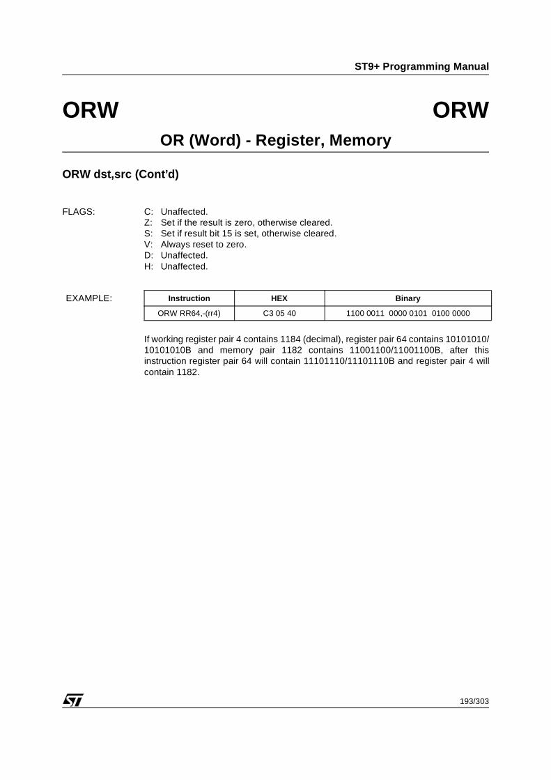
If the carry flag is set, working register pair 4 contains 1184 (decimal), register pair 64contains 5000 (decimal) and memory location 1182 contains 1100 (decimal), after thisinstruction working register pair 64 will contain 6101 and register pair 4 will contain1182.
The source word, along with the carry flag, is added to the destination word and theresult is stored in the destination word. The source word is held in the source register.The destination word can be addressed directly, indirectly or by indexing.
OPERATION b: dst ⇐ dst + src + Crr ⇐ rr + 2
The source word, along with the carry flag, is added to the destination word and theresult is stored in the destination word. The source word is in the source register, thedestination word is in the memory location addressed by the destination register pair.The contents of the destination register pair are incremented after the ADD has beencarried out.
OPERATION c: rr ⇐ rr - 2dst ⇔ dst + src + C
The source word, along with the carry flag, is added to the destination word and theresult is stored in the destination word. The source word is in the source register, thedestination word is in the memory location addressed by the destination register pair.The contents of the destination register pair are decremented before the ADD iscarried out.
INSTRUCTION FORMAT: No.Bytes
No.Cycl
OPC(HEX)
OPCXTN
Addr ModeOper
dst src[ OPC ] [dst,1|src,0] 2 16 3E - (rr) rr a
[ OPC ] [ XTN |dst,1] [ src,0 ] 3 18 BE 3 (rr) RR a
[ OPC ] [ XTN |dst,0] [ ofd h ][ ofd l ] [ src,1 ]
5 20 86 3 NN(rr) RR a
5 20 86 3 NN(rr) rr a
1
82/303
ST9+ Programming Manual
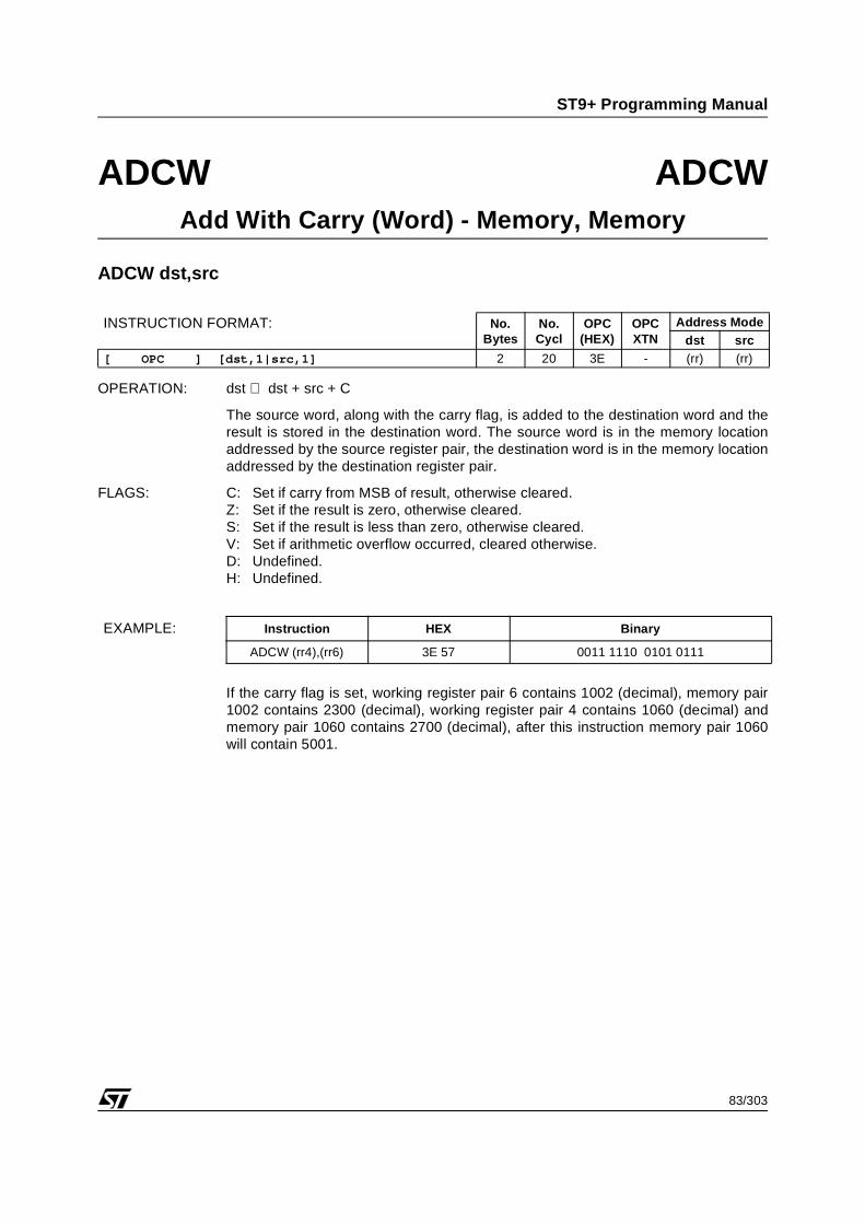
ADCW ADCWAdd With Carry (Word) - Memory, Register
ADCW dst,src (Cont’d)
FLAGS: C: Set if carry from MSB of result, otherwise cleared.Z: Set if the result is zero, otherwise cleared.S: Set if the result is less than zero, otherwise cleared.V: Set if arithmetic overflow occurred, cleared otherwise.D: Undefined.H: Undefined.
If the carry flag is set, register pair 64 contains 1250 (decimal), working register pair4 contains 1064 (decimal), and memory location 1064 contains 1750, after thisinstruction is carried out memory pair 1064 will contain 3001 and working register pair4 will contain 1066.
The source word, along with the carry flag, is added to the destination word and theresult is stored in the destination word. The source word is in the memory locationaddressed by the source register pair, the destination word is in the memory locationaddressed by the destination register pair.
FLAGS: C: Set if carry from MSB of result, otherwise cleared.Z: Set if the result is zero, otherwise cleared.S: Set if the result is less than zero, otherwise cleared.V: Set if arithmetic overflow occurred, cleared otherwise.D: Undefined.H: Undefined.
If the carry flag is set, working register pair 6 contains 1002 (decimal), memory pair1002 contains 2300 (decimal), working register pair 4 contains 1060 (decimal) andmemory pair 1060 contains 2700 (decimal), after this instruction memory pair 1060will contain 5001.
INSTRUCTION FORMAT: No.Bytes
No.Cycl
OPC(HEX)
OPCXTN
Address Modedst src
[ OPC ] [dst,1|src,1] 2 20 3E - (rr) (rr)
EXAMPLE: Instruction HEX Binary
ADCW (rr4),(rr6) 3E 57 0011 1110 0101 0111
1
84/303
ST9+ Programming Manual
ADCW ADCWAdd With Carry (Word) - All, Immediate
ADCW dst,src
OPERATION: dst ⇐ dst + src + C
The source word, along with the carry flag, is added to the destination word and theresult is stored in the destination word. The source word is the immediate value in theoperand, the destination word can be in memory or in the register file.
FLAGS: C: Set if carry from MSB of result, otherwise cleared.Z: Set if the result is zero, otherwise cleared.S: Set if the result is less than zero, otherwise cleared.V: Set if arithmetic overflow occurred, cleared otherwise.D: Undefined.H: Undefined.
If the carry flag is zero and register pair 64 contains 2000 (decimal), after thisinstruction has been carried out register pair 64 will contain the decimal value 6268.
INSTRUCTION FORMAT: No.Bytes
No.Cycl
OPC(HEX)
OPCXTN
Address Modedst src
[ OPC ] [ dst,1 ] [ src h ] [ src l ]
4 10 37 - RR #NN
4 10 37 - rr #NN
[ OPC ] [XTN |dst,0] [ src h ] [ src l ]
4 18 BE 3 (rr) #NN
[ OPC ] [XTN |dst,1] [ ofd ] [ src h ] [ src l ]
5 20 06 3 N(rr) #NN
[ OPC ] [XTN |dst,0] [ ofd h ] [ ofd l ] [ src h ] [ src l ]
6 22 06 3 NN(rr) #NN
[ OPC ] [ XTN ] [ src h ] [ src l ] [ dst h ] [ dst l ]
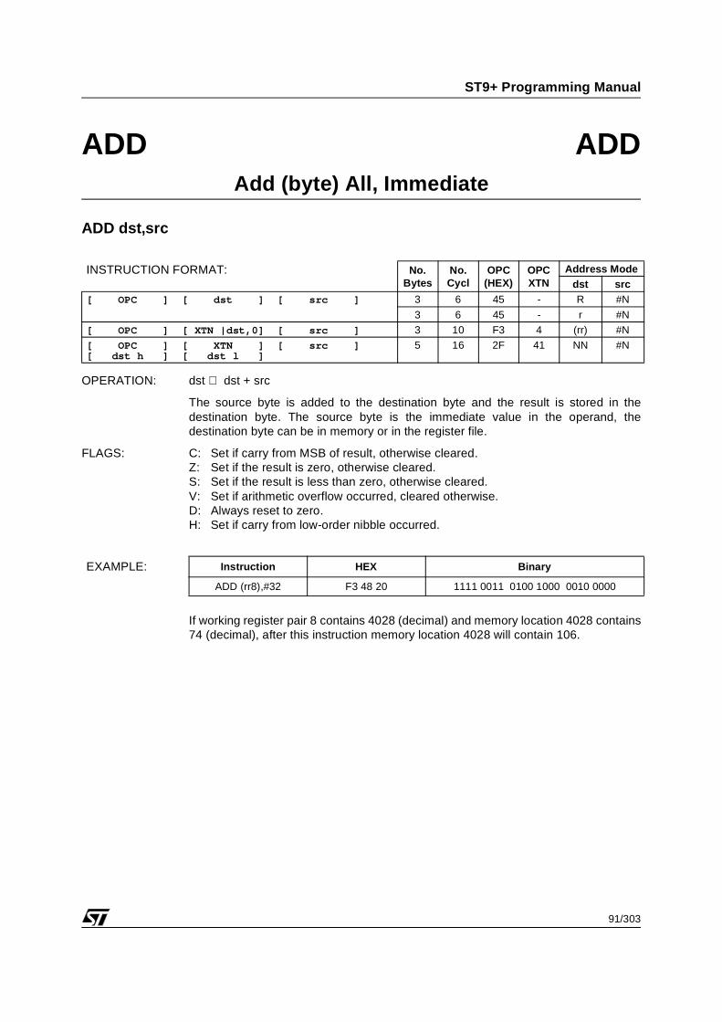
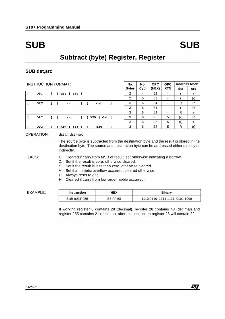
The source byte is added to the destination byte and the result is stored in thedestination byte. The source and destination byte can be addressed either directly orindirectly.
FLAGS: C: Set if carry from MSB of result, otherwise cleared.Z: Set if the result is zero, otherwise cleared.S: Set if the result is less than zero, otherwise cleared.V: Set if arithmetic overflow occurred, cleared otherwise.D: Always reset to zero.H: Set if carry from low-order nibble occurred.
If working register 8 contains 28 (decimal), register 28 contains 43 (decimal) andregister 255 contains 21 (decimal) after this instruction register 28 will contain 64.
The source byte is added to the destination byte and the result is stored in thedestination byte. The destination byte is held in the destination register. The sourcebyte can be addressed directly, indirectly or by indexing.
OPERATION b: dst ⇐ dst + srcrr ⇔ rr + 1
The source byte is added to the destination byte and the result is stored in thedestination byte. The source byte is in the memory location addressed by the sourceregister pair, the destination byte is in the destination register. The contents of thesource register pair are incremented after the ADD has been carried out.
OPERATION c: rr ⇐ rr - 1dst ⇔ dst + src
The source byte is added to the destination byte and the result is stored in thedestination byte. The source byte is in the memory location addressed by the sourceregister pair, the destination byte is in the destination register. The contents of thesource register pair are decremented before the ADD is carried out.
INSTRUCTION FORMAT: No.Bytes
No.Cycl
OPC(HEX)
OPCXTN
Addr ModeOper
dst src[ OPC ] [ XTN |src,1] [ dst ] 3 8 72 4 R (rr) a
3 8 72 4 r (rr) a
3 12 B4 4 R (rr)+ b
3 12 B4 4 r (rr)+ b
3 12 C2 4 R -(rr) c
3 12 C2 4 r -(rr) c
[ OPC ] [ofs,1|src,0] [ XTN | dst ] 3 12 60 4 r rr(rrx) a
[ OPC ] [ XTN |src,1] [ ofs ][ dst ]
4 12 7F 4 R N(rr) a
4 12 7F 4 r N(rr) a
[ OPC ] [ XTN | dst ] [ src h ][ src l ]
4 10 C4 4 r NN a
[ OPC ] [ XTN |src,0] [ ofs h ][ ofs l ] [ dst ]
5 14 7F 4 R NN(rr) a
5 14 7F 4 r NN(rr) a
1
87/303
ST9+ Programming Manual
ADD ADDAdd (byte) Register, Memory
ADD dst,src (Cont’d)
FLAGS: C: Set if carry from MSB of result, otherwise cleared.Z: Set if the result is zero, otherwise cleared.S: Set if the result is less than zero, otherwise cleared.V: Set if arithmetic overflow occurred, cleared otherwise.D: Always reset to zero.H: Set if carry from low-order nibble occurred.
If register 32 contains 207 (decimal), working register pair 4 contains 4200 (decimal)and memory location 4199 contains 27 (decimal), after this instruction register 32 willcontain 234 and working register pair 4 will contain 4199.
The source byte is added to the destination byte and the result is stored in thedestination byte. The source byte is held in the source register. The destination bytecan be addressed directly, indirectly or by indexing.
OPERATION b: dst ⇐ dst + srcrr ⇔ rr + 1
The source byte is added to the destination byte and the result is stored in thedestination byte. The source byte is in the source register, the destination byte is in thememory location addressed by the destination register pair. The contents of thedestination register pair are incremented after the ADD has been carried out.
OPERATION c: rr ⇐ rr - 1dst ⇔ dst + src
The source byte is added to the destination byte and the result is stored in thedestination byte. The source byte is in the source register, the destination byte is in thememory location addressed by the destination register pair. The contents of thedestination register pair are decremented before the ADD is carried out.
INSTRUCTION FORMAT: No.Bytes
No.Cycl
OPC(HEX)
OPCXTN
Addr ModeOper
dst src[ OPC ] [ XTN |dst,0] [ src ] 3 12 72 4 (rr) R a
3 12 72 4 (rr) r a
3 14 B4 4 (rr)+ R b
3 14 B4 4 (rr)+ r b
3 14 C2 4 -(rr) R c
3 14 C2 4 -(rr) r c
[ OPC ] [ofd,1|dst,1] [ XTN | src ] 3 14 60 4 rr(rrx) r a
[ OPC ] [ XTN |dst,1] [ ofd ][ src ]
4 14 26 4 N(rr) R a
4 14 26 4 N(rr) r a
[ OPC ] [ XTN | src ] [ dst h ][ dst l ]
4 12 C5 4 NN r a
[ OPC ] [ XTN |dst,0] [ ofd h ][ ofd l ] [ src ]
5 16 26 4 NN(rr) R a
5 16 26 4 NN(rr) r a
1
89/303
ST9+ Programming Manual
ADD ADDAdd (byte) Memory, Register
ADD dst,src (Cont’d)
FLAGS: C: Set if carry from MSB of result, otherwise cleared.Z: Set if the result is zero, otherwise cleared.S: Set if the result is less than zero, otherwise cleared.V: Set if arithmetic overflow occurred, cleared otherwise.D: Always reset to zero.H: Set if carry from low-order nibble occurred.
If working register pair 8 contains 4028 (decimal), memory location 4034 contains 110(decimal) and register 255 contains 100 (decimal), after this instruction memorylocation 4034 will contain 210.
The source byte is added to the destination byte and the result is stored in thedestination byte. The source byte is in the memory location addressed by the sourceregister pair, the destination byte is in the memory location addressed by thedestination register pair.
FLAGS: C: Set if carry from MSB of result, otherwise cleared.Z: Set if the result is zero, otherwise cleared.S: Set if the result is less than zero, otherwise cleared.V: Set if arithmetic overflow occurred, cleared otherwise.D: Always reset to zero.H: Set if carry from low-order nibble occurred.
If working register pair 4 contains 2800 (decimal) and memory location 2800 contains46 (decimal), working register pair 8 contains 4200 (decimal) and memory location4200 contains 45 (decimal), after this instruction memory location 2800 will contain91.
The source byte is added to the destination byte and the result is stored in thedestination byte. The source byte is the immediate value in the operand, thedestination byte can be in memory or in the register file.
FLAGS: C: Set if carry from MSB of result, otherwise cleared.Z: Set if the result is zero, otherwise cleared.S: Set if the result is less than zero, otherwise cleared.V: Set if arithmetic overflow occurred, cleared otherwise.D: Always reset to zero.H: Set if carry from low-order nibble occurred.
If working register pair 8 contains 4028 (decimal) and memory location 4028 contains74 (decimal), after this instruction memory location 4028 will contain 106.
The source word is added to the destination word and the result is stored in thedestination word. The source and destination words, held in register pairs, can beaddressed either directly or indirectly.
FLAGS: C: Set if carry from MSB of result, otherwise cleared.Z: Set if the result is zero, otherwise cleared.S: Set if the result is less than zero, otherwise cleared.V: Set if arithmetic overflow occurred, cleared otherwise.D: Undefined.H: Undefined.
If working register 8 contains 124, register pair 124 contains 1300 (decimal) andregister pair 64 contains 800 (decimal) after this instruction register pair 64 will contain2100.
The source word is added to the destination word and the result is stored in thedestination word. The destination word is held in the destination register. The sourceword can be addressed directly, indirectly or by indexing.
OPERATION b: dst ⇐ dst + srcrr ⇔ rr + 2
The source word is added to the destination word and the result is stored in thedestination word. The source word is in the memory location addressed by the sourceregister pair, the destination word is in the destination register. The contents of thesource register pair are incremented after the ADD has been carried out.
OPERATION c: rr ⇐ rr - 2dst ⇔ dst + src
The source word is added to the destination word and the result is stored in thedestination word. The source word is in the memory location addressed by the sourceregister pair, the destination word is in the destination register. The contents of thesource register pair are decremented before the ADD is carried out.
INSTRUCTION FORMAT: No.Bytes
No.Cycl
OPC(HEX)
OPCXTN
Addr ModeOper
dst src[ OPC ] [dst,0|src,1] 2 12 4E - rr (rr) a
[ OPC ] [ XTN |src,0] [ dst,0 ] 3 12 7E 4 RR (rr) a
[ OPC ] [ XTN |src,0] [ ofs h ][ ofs l ] [ dst,0 ]
5 16 86 4 RR NN(rr) a
5 16 86 4 rr NN(rr) a
1
94/303
ST9+ Programming Manual
ADDW ADDWAdd (Word) - Register, Memory
ADDW dst,src (Cont’d)
FLAGS: C: Set if carry from MSB of result, otherwise cleared.Z: Set if the result is zero, otherwise cleared.S: Set if the result is less than zero, otherwise cleared.V: Set if arithmetic overflow occurred, cleared otherwise.D: Undefined.H: Undefined.
If working register pair 8 contains 1240 (decimal), memory pair 1240 contains 3000(decimal) and register pair 64 contains 1000 (decimal), after this instruction workingregister pair 64 will contain 4000.
The source word is added to the destination word and the result is stored in thedestination word. The source word is held in the source register. The destination wordcan be addressed directly, indirectly or by indexing.
OPERATION b: dst ⇐ dst + srcrr ⇔ rr + 2
The source word is added to the destination word and the result is stored in thedestination word. The source word is in the source register, the destination word is inthe memory location addressed by the destination register pair. The contents of thedestination register pair are incremented after the ADD has been carried out.
OPERATION c: rr ⇐ rr - 2dst ⇔ dst + src
The source word is added to the destination word and the result is stored in thedestination word. The source word is in the source register, the destination word is inthe memory location addressed by the destination register pair. The contents of thedestination register pair are decremented before the ADD is carried out.
INSTRUCTION FORMAT: No.Bytes
No.Cycl
OPC(HEX)
OPCXTN
Addr ModeOper
dst src[ OPC ] [dst,1|src,0] 2 16 4E - (rr) rr a
[ OPC ] [ XTN |dst,1] [ src,0 ] 3 18 BE 4 (rr) RR a
[ OPC ] [ XTN |dst,0] [ ofd h ][ ofd l ] [ src,1 ]
5 20 86 4 NN(rr) RR a
5 20 86 4 NN(rr) rr a
1
96/303
ST9+ Programming Manual
ADDW ADDWAdd (Word) - Memory, Register
ADDW dst,src (Cont’d)
FLAGS: C: Set if carry from MSB of result, otherwise cleared.Z: Set if the result is zero, otherwise cleared.S: Set if the result is less than zero, otherwise cleared.V: Set if arithmetic overflow occurred, cleared otherwise.D: Undefined.H: Undefined.
If register pair 64 contains 1250 (decimal), working register pair 4 contains 1064(decimal), and memory pair 1064 contains 1750, after this instruction is carried outmemory pair 1064 will contain 3000 and working register pair 4 will contain 1066.
The source word is added to the destination word and the result is stored in thedestination word. The source word is in the memory location addressed by the sourceregister pair, the destination word is in the memory location addressed by thedestination register pair.
FLAGS: C: Set if carry from MSB of result, otherwise cleared.Z: Set if the result is zero, otherwise cleared.S: Set if the result is less than zero, otherwise cleared.V: Set if arithmetic overflow occurred, cleared otherwise.D: Undefined.H: Undefined.
If working register pair 6 contains 1002 (decimal), memory pair 1002 contains 2300(decimal), working register pair 4 contains 1060 (decimal) and memory pair 1060contains 2700 (decimal), after this instruction memory pair 1060 will contain 5000.
INSTRUCTION FORMAT: No.Bytes
No.Cycl
OPC(HEX)
OPCXTN
Address Modedst src
[ OPC ] [dst,1|src,1] 2 20 4E - (rr) (rr)
EXAMPLE: Instruction HEX Binary
ADDW (rr4),(rr6) 4E 57 0100 1110 0101 0111
1
98/303
ST9+ Programming Manual
ADDW ADDWAdd (Word) - All, Immediate
ADDW dst,src
OPERATION: dst ⇐ dst + src
The source word is added to the destination word and the result is stored in thedestination word. The source word is the immediate value in the operand, thedestination word can be in memory or in the register file.
FLAGS: C: Set if carry from MSB of result, otherwise cleared.Z: Set if the result is zero, otherwise cleared.S: Set if the result is less than zero, otherwise cleared.V: Set if arithmetic overflow occurred, cleared otherwise.D: Undefined.H: Undefined.
If register pair 64 contains 2000 (decimal), after this instruction has been carried outregister pair 64 will contain the decimal value 6268.
INSTRUCTION FORMAT: No.Bytes
No.Cycl
OPC(HEX)
OPCXTN
Address Modedst src
[ OPC ] [ dst,1 ] [ src h ][ src l ]
4 10 47 - RR #NN
4 10 47 - rr #NN
[ OPC ] [ XTN |dst,0] [ src h ][ src l ]
4 18 BE 4 (rr) #NN
[ OPC ] [ XTN |dst,1] [ ofd ][ src h ] [ src l ]
5 20 06 4 N(rr) #NN
[ OPC ] [ XTN |dst,0] [ ofd h ][ ofd l ] [ src h ] [ src l ]
6 22 06 4 NN(rr) #NN
[ OPC ] [ XTN ] [ src h ][ src l ] [ dst h ] [ dst l ]
The contents of the source are ANDed with the destination byte and the results storedin the destination byte. The contents of the source are not affected.
FLAGS: C: Unaffected.Z: Set if the result is zero, otherwise cleared.S: Set if result bit 7 is set, otherwise cleared.V: Always reset to zero.D: Unaffected.H: Unaffected.
If working register 8 contains 11001100 and register 64 contains 10000101, after thisinstruction working register 8 will contain 10000100.
INSTRUCTION FORMAT: No.Bytes
No.Cycl
OPC(HEX)
OPCXTN
Address Modedst src
[ OPC ] [ dst | src ] 2 4 12 - r r
2 6 13 - r (r)
[ OPC ] [ src ] [ dst ] 3 6 14 - R R
3 6 14 - r R
3 6 14 - R r
[ OPC ] [ src ] [ XTN | dst ] 3 6 E6 1 (r) R
3 6 E6 1 (r) r
[ OPC ] [ XTN | src ] [ dst ] 3 6 E7 1 R (r)
EXAMPLE: Instruction HEX Binary
AND r8,R64 14 40 D8 0001 0100 0100 0000 1101 1000
1
100/303
ST9+ Programming Manual
AND ANDAND (byte) Register, Memory
AND dst,src
OPERATION a: dst ⇐ dst AND src
The source byte is ANDed with the destination byte and the result stored in thedestination byte. The destination register is addressed directly, the memory location isaddressed either directly, indirectly or by indexing.
OPERATION b: dst ⇐ dst AND src rr ⇐ rr + 1
The contents of the memory location addressed by the source register pair areANDed with the contents of the directly addressed destination register the resultstored in the destination byte. The contents of the source register pair areincremented after the AND has been carried out.
OPERATION c: rr ⇐ rr - 1 dst ⇐ dst AND src
The contents of the source register pair are decremented and then the contents of thememory location addressed by the source register pair are ANDed with the contentsof the directly addressed destination register. The result is stored in the destinationbyte.
FLAGS: C: Unaffected.Z: Set if the result is zero, otherwise cleared.S: Set if result bit 7 is set, otherwise cleared.V: Always reset to zero.D: Unaffected.H: Unaffected.
INSTRUCTION FORMAT: No.Bytes
No.Cycl
OPC(HEX)
OPCXTN
Addr ModeOper
dst src[ OPC ] [ XTN |src,1] [ dst ] 3 8 72 1 R (rr) a
3 8 72 1 r (rr) a
3 12 B4 1 R (rr)+ b
3 12 B4 1 r (rr)+ b
3 12 C2 1 R -(rr) c
3 12 C2 1 r -(rr) c
[ OPC ] [ofs,1|src,0] [ XTN | dst ] 3 12 60 1 r rr(rrx) a
[ OPC ] [ XTN |src,1] [ ofs ][ dst ]
4 12 7F 1 R N(rr) a
4 12 7F 1 r N(rr) a
[ OPC ] [ XTN | dst ] [ src h ][ src l ]
4 10 C4 1 r NN a
[ OPC ] [ XTN |src,0] [ ofs h ][ ofs l ] [ dst ]
5 14 7F 1 R NN(rr) a
5 14 7F 1 r NN(rr) a
1
101/303
ST9+ Programming Manual
AND ANDAND (byte) Register, Memory
AND dst,src (Cont’d)
If working register 8 contains 11001100 and memory location 4028 contains10000101, after this instruction working register 8 will contain 10000100.
EXAMPLE: Instruction HEX Binary
AND r8,4028 C4 18 0F BC 1100 0100 0001 1000 0000 1111 1011 1100
1
102/303
ST9+ Programming Manual
AND ANDAND (byte) Memory, Register
AND dst,src
OPERATION a: dst ⇐ dst AND src
The source byte is ANDed with the destination byte and the result stored in thedestination byte. The source registers are addressed directly, the memory locationare addressed either directly, indirectly or by indexing.
OPERATION b: dst ⇐ dst AND src rr ⇐ rr + 1
The contents of the memory location addressed by the destination register pair(destination byte) are ANDed with the contents of the directly addressed sourceregister the result stored in the destination byte. The contents of the destinationregister pair are incremented after the AND has been carried out.
OPERATION c: rr ⇐ rr - 1 dst ⇐ dst AND src
The contents of the destination register pair are decremented and then the contentsof the memory location addressed by the destination register pair (destination byte)are ANDed with the contents of the directly addressed source register. The result isstored in the destination byte.
FLAGS: C: Unaffected.Z: Set if the result is zero, otherwise cleared.S: Set if result bit 7 is set, otherwise cleared.V: Always reset to zero.D: Unaffected.H: Unaffected.
INSTRUCTION FORMAT: No.Bytes
No.Cycl
OPC(HEX)
OPCXTN
Addr ModeOper
dst src[ OPC ] [ XTN |dst,0] [ src ] 3 12 72 1 (rr) R a
3 12 72 1 (rr) r a
3 14 B4 1 (rr)+ R b
3 14 B4 1 (rr)+ r b
3 14 C2 1 -(rr) R c
3 14 C2 1 -(rr) r c
[ OPC ] [ofd,1|dst,1] [ XTN | src ] 3 14 60 1 rr(rrx) r a
[ OPC ] [ XTN |dst,1] [ ofd ][ src ]
4 14 26 1 N(rr) R a
4 14 26 1 N(rr) r a
[ OPC ] [ XTN | src ] [ dst h ][ dst l ]
4 12 C5 1 NN r a
[ OPC ] [ XTN |dst,0] [ ofd h ][ ofd l ] [ src ]
5 16 26 1 NN(rr) R a
5 16 26 1 NN(rr) r a
1
103/303
ST9+ Programming Manual
AND ANDAND (byte) Memory, Register
AND dst,src (Cont’d)
If working register 8 contains 11001100 and memory location 4028 contains10000101, after this instruction memory location 4028 will contain 10000100.
EXAMPLE: Instruction HEX Binary
AND 4028,r8 C5 18 0F BC 1100 0101 0001 1000 0000 1111 1011 1100
1
104/303
ST9+ Programming Manual
AND ANDAND (byte) Memory, Memory
AND dst,src
OPERATION: dst ⇐ dst AND src
The contents of the memory location addressed by the source register pair areANDed with the content of the memory location addressed by the destination registerpair. The source and destination addresses are for the word high order byte.
FLAGS: C: Unaffected.Z: Set if the result is zero, otherwise cleared.S: Set if result bit 7 is set, otherwise cleared.V: Always reset to zeroD: Unaffected.H: Unaffected.
If working register pair 4 contains 2800 (decimal), memory location 2800 contains11001100, working register pair 8 contains 4200 (decimal) and memory location 4200contains 11000011, after this instruction memory location 2800 will contain11000000.
The value #N is ANDed with the content of the destination register or memory location(destination byte) and stored in the destination byte.
FLAGS: C: Unaffected.Z: Set if the result is zero, otherwise cleared.S: Set if result bit 7 is set, otherwise cleared.V: Always reset to zero.D: Unaffected.H: Unaffected.
If working register pair 8 contains 4028 (decimal) and memory location 4028 contains11101100, after this instruction memory location 4028 will contain 00100000.
The source word is ANDed with the destination word. The result is left in thedestination. The source and destination words can be addressed either directly orindirectly.
FLAGS: C: Unaffected.Z: Set if the result is zero, otherwise cleared.S: Set if result bit 15 is set, otherwise cleared.V: Always reset to zero.D: Undefined.H: Undefined.
If register pair 64 contains 11001100/11001100B and register pair 32 contains10101010/10101010B, after this instruction register pair 32 will contain 10001000/10001000B.
The source word is ANDed with the destination word. The result is left in thedestination word. The destination word is held in the destination register. The sourceword can be addressed directly, indirectly or by indexing. The contents of the sourceare not affected.
OPERATION b: dst ⇐ dst AND src rr ⇐ rr + 2
The source word is ANDed with the destination word. The result is left in thedestination word. The source word is in the memory location addressed by the sourceregister pair, the destination word is in the destination register. The contents of thesource register pair are incremented after the AND has been carried out.
OPERATION c: rr ⇐ rr - 2 dst ⇐ dst AND src
The source word is ANDed with the destination word. The result is left in thedestination word. The source word is in the memory location addressed by the sourceregister pair, the destination word is in the destination register. The contents of thesource register pair are decremented before the AND is carried out.
INSTRUCTION FORMAT: No.Bytes
No.Cycl
OPC(HEX)
OPCXTN
Addr ModeOper
dst src[ OPC ] [dst,0|src,1] 2 12 1E - rr (rr) a
[ OPC ] [ XTN |src,0] [ dst,0 ] 3 12 7E 1 RR (rr) a
[ OPC ] [ XTN |src,0] [ ofs h ][ ofs l ] [ dst,0 ]
5 16 86 1 RR NN(rr) a
5 16 86 1 rr NN(rr) a
1
108/303
ST9+ Programming Manual
ANDW ANDWAND (Word) - Register, Memory
ANDW dst,src (Cont’d)
FLAGS: C: Unaffected.Z: Set if the result is zero, otherwise cleared.S: Set if result bit 15 is set, otherwise cleared.V: Always reset to zero.D: Undefined.H: Undefined.
If working register pair 4 contains 1184 (decimal), register pair 64 contains 10101010/10101010B and memory pair 1184 contains 11001100/11001100B, after thisinstruction register pair 64 will contain 10001000/10001000B and register pair 4 willcontain 1186.
The source word is ANDed with the destination word. The result is stored in thedestination word. The source word is held in the source register pair. The destinationword can be addressed directly, indirectly or by indexing.
OPERATION b: dst ⇐ dst AND src rr ⇐ rr + 2
The source word is ANDed with the destination word. The result is stored in thedestination word. The source word is in the source register pair, the destination wordis in the memory location addressed by the destination register pair. The contents ofthe destination register pair are incremented after the AND has been carried out.
OPERATION c: rr ⇐ rr - 2 dst ⇐ dst AND src
The source word is ANDed with the destination word. The result is stored in thedestination word. The source word is in the source register pair, the destination wordis in the memory pair addressed by the destination register pair. The contents of thedestination register pair are decremented before the AND is carried out.
FLAGS: C: Unaffected.Z: Set if the result is zero, otherwise cleared.S: Set if result bit 15 is set, otherwise cleared.V: Always reset to zero.D: Undefined.H: Undefined.
INSTRUCTION FORMAT: No.Bytes
No.Cycl
OPC(HEX)
OPCXTN
Addr ModeOper
dst src[ OPC ] [dst,1|src,0] 2 16 1E - (rr) rr a
[ OPC ] [ XTN |dst,1] [ src,0 ] 3 18 BE 1 (rr) RR a
[ OPC ] [ XTN |dst,0] [ ofd h ][ ofd l ] [ src,1 ]
5 20 86 1 NN(rr) RR a
5 20 86 1 NN(rr) rr a
1
110/303
ST9+ Programming Manual
ANDW ANDWAND (Word) - Memory, Register
ANDW dst,src (Cont’d)
If register pair 64 contains 11001100/11001100B, working register pair 8 contains2000 (decimal) and memory pair 2000 contains 10101010/10101010B, after thisinstruction memory pair 2000 will hold 10001000/10001000B.
The source word is ANDed with the destination word. The result is stored in thedestination word. The source word is in the memory pair addressed by the sourceregister pair, the destination word is in the memory pair addressed by the destinationregister pair.
FLAGS: C: Unaffected.Z: Set if the result is zero, otherwise cleared.S: Set if result bit 15 is set, otherwise cleared.V: Always reset to zero.D: Undefined.H: Undefined.
If working register pair 6 contains register 1002 (decimal), memory pair 1002 contains11001100/11001100B, working register pair 4 contains 1060 (decimal), and memorypair 1060 contains 10101010/10101010B, after this instruction memory pair 1060 willcontain 10001000/10001000B.
INSTRUCTION FORMAT: No.Bytes
No.Cycl
OPC(HEX)
OPCXTN
Address Modedst src
[ OPC ] [dst,1|src,1] 2 20 1E - (rr) (rr)
EXAMPLE: Instruction HEX Binary
ANDW (rr4),(rr6) 1E 57 0001 1110 0101 0111
1
112/303
ST9+ Programming Manual
ANDW ANDWAND (Word) - All, Immediate
ANDW dst,src
OPERATION: dst ⇐ dst AND src
The source word is ANDed with the destination word. The result is stored in thedestination word. The source word is the immediate value in the operand, thedestination word can be in memory or in the register file.
FLAGS: C: Unaffected.Z: Set if the result is zero, otherwise cleared.S: Set if result bit 15 is set, otherwise cleared.V: Always reset to zero.D: Undefined.H: Undefined.
If register pair 64 contains 10101010/10101010B, after this instruction has beencarried out register pair 64 will contain 10001000/10001000B.
INSTRUCTION FORMAT: No.Bytes
No.Cycl
OPC(HEX)
OPCXTN
Address Modedst src
[ OPC ] [ dst,1 ] [ src h ][ src l ]
4 10 17 - RR #NN
4 10 17 - rr #NN
[ OPC ] [ XTN |dst,0] [ src h ][ src l ]
4 18 BE 1 (rr) #NN
[ OPC ] [ XTN |dst,1] [ ofd ][ src h ] [ src l ]
5 20 06 1 N(rr) #NN
[ OPC ] [ XTN |dst,0] [ ofd h ][ ofd l ] [ src h ] [ src l ]
6 22 06 1 NN(rr) #NN
[ OPC ] [ XTN ] [ src h ][ src l ] [ dst h ] [ dst l ]
6 22 36 11 NN #NN
EXAMPLE: Instruction HEX Binary
ANDW RR64,#52428 17 41 CC CC 0001 0111 0100 0001 1100 1100 1100 1100
1
113/303
ST9+ Programming Manual
BAND BANDBit AND
BAND dst.b,src.b
OPERATION a: dst bit ⇐ dst bit AND src bit
The selected bit in the source working register is ANDed with the selected bit of thedestination working register and the result left in the destination bit. All other bits in thedestination register remain unaffected. Both source and destination are directlyaddressed.
OPERATION b: dst bit ⇐ dst bit AND NOT src bit
The complement of the selected bit in the source working register is ANDed with theselected bit of the destination working register and the result left in the destination bit.All other bits in the destination register remain unaffected. Both source anddestination are directly addressed.
FLAGS: No flags affected.
If bit 2 of working register 8 is 0 and bit 5 of working register 4 is 1, after this instructionbit 5 of working register 4 will be 0.
NOTE: A bit AND can use the same or different nibbles of the same register as both sourceand destination.
The selected bit in the destination working register is set to its own complement. Allother bits in the destination register remain unaffected. The destination is directlyaddressed.
FLAGS: No flags affected.
If bit 5 of working register 4 was 1, after this instruction it will be 0.
INSTRUCTION FORMAT: No.Bytes
No.Cycl
OPC(HEX)
OPCXTN
Address Modedst src
[ OPC ] [btd,0| dst ] 2 4 6F - r.b -
EXAMPLE: Instruction HEX Binary
BCPL r4.5 6F A4 0110 1111 1010 0100
1
115/303
ST9+ Programming Manual
BLD BLDBit Load
BLD dst.b,src.b
OPERATION a: dst bit ⇐ src bit
The selected bit in the source working register is loaded into the selected bit of thedestination working register. All other bits in the destination register remainunaffected. Both source and destination are directly addressed.
OPERATION b: dst bit ⇐ NOT src bit
The complement of the selected bit in the source working register is loaded into theselected bit of the destination working register. All other bits in the destination registerremain unaffected. Both source and destination are directly addressed.
FLAGS: No flags affected.
If bit 2 of working register 8 is 1, after this instruction bit 5 of working register 4 will be0.
NOTE: A bit load can use the same or different nibbles of the same register as both source and destination.
The selected bit in the source working register is ORed with the selected bit of thedestination register and the result left in the destination bit. All other bits in thedestination register remain unaffected. Both source and destination are directlyaddressed.
OPERATION b: dst bit ⇐ dst bit OR NOT src bit
The complement of the selected bit in the source working register is ORed with theselected bit of the destination working register and the result left in the destination bit.All other bits in the destination register remain unaffected. Both source anddestination are directly addressed.
FLAGS: No flags affected.
If bit 2 of working register 8 is 1 and bit 5 of working register 4 is 0, after this instructionbit 5 of working register 4 will be 1.
NOTE: A bit OR can use the same or different nibbles of the same register as both source and destination.
The selected bit in the destination working register is reset to 0. All other bits in thedestination register remain unaffected. The destination is directly addressed.
FLAGS: No flags affected.
After this instruction bit 5 of working register 4 will be 0.
INSTRUCTION FORMAT: No.Bytes
No.Cycl
OPC(HEX)
OPCXTN
Address Modedst src
[ OPC ] [btd,0| dst ] 2 4 1F - r.b -
EXAMPLE: Instruction HEX Binary
BRES r4.5 1F A4 0001 1111 1010 0100
1
118/303
ST9+ Programming Manual
BSET BSETBit Set
BSET dst.b
OPERATION: dst bit ⇐ 1
The selected bit in the destination working register is set to 1. All other bits in thedestination register remain unaffected. The destination is directly addressed.
FLAGS: No flags affected.
After this instruction bit 5 of working register 4 will be 1.
INSTRUCTION FORMAT: No.Bytes
No.Cycl
OPC(HEX)
OPCXTN
Address Modedst src
[ OPC ] [btd,0| dst ] 2 4 0F - r.b -
EXAMPLE: Instruction HEX Binary
BSET r4.5 0F A4 0000 1111 1010 0100
1
119/303
ST9+ Programming Manual
BTJF BTJFBit Test And Jump If False
BTJF dst,src
OPERATION: If tested bit is zero then PC ⇐ PC + N where -128 ≥ N ≥ 127
The specified bit in the destination working register is tested and if it is found to beequal to zero, the source value N is added to the program counter and control passesto the statement whose address is now in the PC. If the tested bit is one, theinstruction following BTJF is executed. N is a relative value in the range +127/-128.
FLAGS: No flags affected.
If bit 2 of working register 10 is zero and the program counter holds 200, after thisinstruction the program counter will jump to address 160.
OPERATION: If tested bit is one then PC ⇐ PC + N where -128 ≥ N ≥ 127
The specified bit in the destination working register is tested and if it is found to beequal to one, the source value N is added to the program counter and control passesto the statement whose address is now in the PC. If the tested bit is zero theinstruction following BTJT is executed. N is a relative value in the range +127/-128.
FLAGS: No flags affected.
If bit 2 of working register 10 is a one and the program counter holds 200, after thisinstruction the program counter will jump to address 240.
The selected bit in the destination is tested; if zero it is set to one and the zero flag set.The destination is addressed either by working register direct or memory indirect.
FLAGS: C: Unaffected.Z: Set if bit was zero, otherwise cleared.S: Set if bit 7 is tested and was set, otherwise cleared.V: Always reset to zero.D: Unaffected.H: Unaffected.
If bit 5 of working register 4 is 0, after this instruction it is set to 1 and the zero flag isalso set to 1.
INSTRUCTION FORMAT: No.Bytes
No.Cycl
OPC(HEX)
OPCXTN
Addr ModeOper
dst src[ OPC ] [btd,0| dst ] 2 8 F2 - r.b -
[ OPC ] [btd,0| dst,0 ] 2 14 F6 - (rr).b -
EXAMPLE: Instruction HEX Binary
BTSET r4.5 F2 A4 1111 0010 1010 0100
1
122/303
ST9+ Programming Manual
BXOR BXORBit XOR
BXOR dst.b,src.b
OPERATION a: dst bit ⇐ dst bit XOR src bit
The selected bit in the source working register is XORed with the selected bit of thedestination register and the result left in the destination bit. All other bits in thedestination register remain unaffected. Both source and destination are directlyaddressed.
OPERATION b: dst bit ⇐ dst bit XOR NOT src bit
The complement of the selected bit in the source working register is XORed with theselected bit of the destination working register and the result left in the destination bit.All other bits in the destination register remain unaffected. Both source anddestination are directly addressed.
FLAGS: No flags affected.
If bit 2 of working register 8 is 1 and bit 5 of working register 4 is 0, after this instructionbit 5 of working register 4 will be 1.
NOTE: A bit XOR can use the same or different nibbles of the same register as both source and destination.
The current contents of the program counter (PC) are pushed onto the top of thesystem stack. (The program counter value used is the address of the first instructionbyte following the CALL instruction). The specified destination address is then loadedinto the PC and points to the first instruction of the CALL procedure.
In direct memory addressing mode the destination is in the memory locationaddressed by the absolute value in the operand.
In the indirect memory addressing mode the destination is in the memory locationaddressed by the contents of the destination register pair.
FLAGS: No flags affected.
If the content of the program counter is 1A47 (hex) and the content of the system stackpointer is 3002 (hex) the above instruction will cause the stack pointer to bedecremented to 3000 (hex), 1A4A (the address following the instruction) is stored inexternal data memory 3000 (hex) and 3001 (hex), and the program counter is loadedwith 3521 (hex). The program counter now points to the address of the first statementin the procedure to be executed.
This instruction uses a different stack frame, saving both the PC and the CSR on thestack.
The current content of the program counter (PC) and then, the content of the CSR arepushed onto the top of the system stack. (The program counter value used is theaddress of the first instruction byte following the CALLS instruction). The specifieddestination address is then loaded into the CSR and PC and points to the firstinstruction of the CALLS procedure.
In direct memory addressing mode the destination is in the memory locationaddressed by the absolute value in the operands.
In the indirect memory addressing mode the destination is in the memory locationaddressed by the contents of the destination registers.
FLAGS: No flags affected.
INSTRUCTION FORMAT: No.Bytes
No.Cycl
OPC(HEX)
OPCXTN
Address Modedst seg
[ OPC ] [ seg ] [ dst h ] [ dst l ] 4 16 3F 01xx xxxx NN N
[ OPC ] [ dst,1 ] [ seg ]3 18 73 - (rr) (R)
3 18 73 - (rr) (r)
1
125/303
ST9+ Programming Manual
If the content of the PC is 1A47 (hex), the content of CSR is 6 and the content of thesystem stack pointer is 3003 (hex) the above instruction will cause the stack pointerto be decremented to 3000 (hex), 1A4B (the address following the instruction) isstored in external data memory 3000 (hex) and 3001 (hex), the value 6 (CSR) isstored in 3002 (hex), CSR and PC are loaded with 12, 3521 (hex). The programcounter now points to the address of the first statement in the procedure to beexecuted.
The carry flag is complemented; if C=1 it is changed to C=0 and vice-versa.
FLAGS: C: Complemented.No other flags affected.
If the carry flag is set to one, after this instruction it will be reset to zero.
INSTRUCTION FORMAT: No.Bytes
No.Cycl
OPC(HEX)
OPCXTN
Address Modedst src
[ OPC ] 1 4 61 - - -
EXAMPLE: Instruction HEX Binary
CCF 61 0110 0001
1
127/303
ST9+ Programming Manual
CLR CLRClear Register
CLR dst
OPERATION: dst ⇐ 0
The contents of destination register, directly or indirectly addressed, is cleared tozero.
FLAGS: No flags affected.
If register 32 holds 142, after this instruction register 142 will contain 0.
INSTRUCTION FORMAT: No.Bytes
No.Cycl
OPC(HEX)
OPCXTN
Address Modedst src
[ OPC ] [ dst ] 2 4 90 - R -
2 4 90 - r -
2 4 91 - (R) -
2 4 91 - (r) -
EXAMPLE: Instruction HEX Binary
CLR (R32) 91 20 1001 0001 0010 0000
1
128/303
ST9+ Programming Manual
CP CPCompare (byte) Register, Register
CP dst,src
OPERATION: dst - src
The source byte is compared with (subtracted from) the destination byte and C, Z, Sand V flags are affected. The destination byte remains unaffected. The source anddestination byte can be addressed either directly or indirectly.
FLAGS: C: Cleared if carry from MSB, otherwise set indicating a borrow.Z: Set if the result is zero, otherwise cleared.S: Set if the result is less than zero, otherwise cleared.V: Set if arithmetic overflow occurred, cleared otherwise.D: Unaffected.H: Unaffected.
If working register 8 contains 28 (decimal), register 28 contains 11001100 and register255 contains 10000101, after this instruction: Z, C , S and V flags will be reset to zero.
The source byte is compared with (subtracted from) the destination byte and C, Z, Sand V flags are affected The destination byte remains unaffected. The destinationbyte is held in the destination register. The source byte can be addressed directly,indirectly or by indexing.
OPERATION b: dst - src rr ⇐ rr + 1
The source byte is compared with (subtracted from) the destination byte and C, Z, Sand V flags are affected. The destination byte remains unaffected. The source byte isin the memory location addressed by the source register pair, the destination byte isin the destination register. The contents of the source register pair are incrementedafter the CP has been carried out.
OPERATION c: rr ⇐ rr - 1 dst - src
The source byte is compared with (subtracted from) the destination byte and C, Z, Sand V flags are affected. The destination byte remains unaffected. The source byte isin the memory location addressed by the source register pair, the destination byte isin the destination register. The contents of the source register pair are decrementedbefore the CP is carried out.
INSTRUCTION FORMAT: No.Bytes
No.Cycl
OPC(HEX)
OPCXTN
Addr ModeOper
dst src[ OPC ] [ XTN |src,1] [ dst ] 3 8 72 9 R (rr) a
3 8 72 9 r (rr) a
3 12 B4 9 R (rr)+ b
3 12 B4 9 r (rr)+ b
3 12 C2 9 R -(rr) c
3 12 C2 9 r -(rr) c
[ OPC ] [ofs,1|src,0] [ XTN | dst ] 3 12 60 9 r rr(rrx) a
[ OPC ] [ XTN |src,1] [ ofs ][ dst ]
4 12 7F 9 R N(rr) a
4 12 7F 9 r N(rr) a
[ OPC ] [ XTN | dst ] [ src h ][ src l ]
4 10 C4 9 r NN a
[ OPC ] [ XTN |src,0] [ ofs h ][ ofs l ] [ dst ]
5 14 7F 9 R NN(rr) a
5 14 7F 9 r NN(rr) a
1
130/303
ST9+ Programming Manual
CP CPCompare (byte) Register, Memory
CP dst,src (Cont’d)
FLAGS: C: Cleared if carry from MSB, otherwise set indicating a borrow.Z: Set if the result is zero, otherwise cleared.S: Set if the result is less than zero, otherwise cleared.V: Set if arithmetic overflow occurred, cleared otherwise.D: Unaffected.H: Unaffected.
If register 32 contains 11001100, working register pair 4 contains 4200 (decimal) andmemory location 4199 contains 11001100, after this instruction, C, S, V flags will bereset to zero, the zero flag will be set to one and working register pair 4 will contain4199.
The source byte is compared with (subtracted from) the destination byte and C, Z, Sand V flags are affected. The destination byte remains unaffected. The source byte isheld in the source register. The destination byte can be addressed directly, indirectlyor by indexing.
OPERATION b: dst - src rr ⇐ rr + 1
The source byte is compared with (subtracted from) the destination byte and C, Z, Sand V flags are affected. The destination byte remains unaffected. The source byte isin the source register, the destination byte is in the memory location addressed by thedestination register pair. The contents of the destination register pair are incrementedafter the CP has been carried out.
OPERATION c: rr ⇐ rr - 1 dst - src
The source byte is compared with (subtracted from) the destination byte and C, Z, Sand V flags are affected. The destination byte remains unaffected. The source byte isin the source register, the destination byte is in the memory location addressed by thedestination register pair. The contents of the destination register pair are decrementedbefore the CP is carried out.
INSTRUCTION FORMAT: No.Bytes
No.Cycl
OPC(HEX)
OPCXTN
Addr ModeOper
dst src[ OPC ] [ XTN |dst,0] [ src ] 3 10 72 9 (rr) R a
3 10 72 9 (rr) r a
3 12 B4 9 (rr)+ R b
3 12 B4 9 (rr)+ r b
3 12 C2 9 -(rr) R c
3 12 C2 9 -(rr) r c
[ OPC ] [ofd,1|dst,1] [ XTN | src ] 3 12 60 9 rr(rrx) r a
[ OPC ] [ XTN |dst,1] [ ofd ][ src ]
4 12 26 9 N(rr) R a
4 12 26 9 N(rr) r a
[ OPC ] [ XTN | src ] [ dst h ][ dst l ]
4 10 C5 9 NN r a
[ OPC ] [ XTN |dst,0] [ ofd h ][ ofd l ] [ src ]
5 14 26 9 NN(rr) R a
5 14 26 9 NN(rr) r a
1
132/303
ST9+ Programming Manual
CP CPCompare (byte) Memory, Register
CP dst,src (Cont’d)
FLAGS: C: Cleared if carry from MSB, otherwise set indicating a borrow.Z: Set if the result is zero, otherwise cleared.S: Set if the result is less than zero, otherwise cleared.V: Set if arithmetic overflow occurred, cleared otherwise.D: Unaffected.H: Unaffected.
If memory location 4028 contains 11001100 and working register 8 contains10000101, after this instruction the zero flag will be reset to zero.
The source byte is compared with (subtracted from) the destination byte and C, Z, Sand V flags are affected. The destination byte remains unaffected. The source byte isin the memory location addressed by the source register pair, the destination byte isin the memory location addressed by the destination register pair.
FLAGS: C: Cleared if carry from MSB, otherwise set indicating a borrow.Z: Set if the result is zero, otherwise cleared.S: Set if the result is less than zero, otherwise cleared.V: Set if arithmetic overflow occurred, cleared otherwise.D: Unaffected.H: Unaffected.
If working register pair 4 contains 2800 (decimal), memory location 2800 contains11001100, working register pair 8 contains 4200 (decimal) and memory location 4200contains 11001100, after this instruction the zero flag will be set to one.
The source byte is compared with (subtracted from) the destination byte and C, Z, Sand V flags are affected. The destination byte remains unaffected. The source byte isthe immediate value in the operand, the destination byte can be in memory or in theregister file.
FLAGS: C: Cleared if carry from MSB, otherwise set indicating a borrow.Z: Set if the result is zero, otherwise cleared.S: Set if the result is less than zero, otherwise cleared.V: Set if arithmetic overflow occurred, cleared otherwise.D: Unaffected.H: Unaffected.
If working register pair 8 contains 4028 (decimal) and memory location 4028 contains11101100, after this instruction the zero flag will be reset to zero.
CPJFI CPJFICompare And Jump If False Otherwise Post-Increment
CPJFI dst,src,N
OPERATION: If compare not verified jump, otherwise increment source register pair.
The source operand is compared to (subtracted from) the destination operand. If theresult is different from zero the offset N (where N is in the range -128/+127) is addedto the program counter and control passes to the statement whose address is now inthe PC, otherwise the source pointer is incremented by one and the instructionfollowing the CPJFI is executed.
FLAGS: No flags affected.
If the current value of the program counter is 340 (decimal) and working register 2contains 11001100B, working register pair 14 contains 3000 (decimal) and memorylocation 3000 holds 10000100B the program counter will now point at programlocation 440 (decimal).
NOTE: The source value must exist within the destination area (or limit checks must be included).
INSTRUCTION FORMAT:No.
Bytes
No.CyclOPC
(HEX)
Addr ModePC
offs.No Jmp
Jmp dst src
[ OPC ] [src,0| dst ] [ PC Offset ] 3 14 16 9F r (rr) N
CPJTI CPJTICompare And Jump If True Otherwise Post-Increment
CPJTI dst,src,N
OPERATION: If compare verified jump, otherwise increment source registers pair.
The source operand is compared to (subtracted from) the destination operand. If theresult is zero the offset N (where N is in the range -128/+127) is added to the programcounter and control passes to the statement whose address is now in the PC,otherwise the source pointer is incremented by one and the instruction following theCPJTI is executed.
FLAGS: No flags affected.
If the current value of the program counter is 340 (decimal) and working register 2contains 11001100B, working register pair 14 contains 3000 (decimal) and memorylocation 3000 holds 11001100B the program counter will now point at programlocation 440 (decimal).
NOTE: The source value must exist within the destination area (or limit checks must be included).
INSTRUCTION FORMAT:No.
Bytes
No.CyclOPC(HEX)
Addr ModePC
offs.No Jmp
Jmp dst src
[ OPC ] [src,1| dst ] [ PC Offset ] 3 14 16 9F r (rr) N
The contents of the destination register, directly or indirectly addressed, are onecomplemented (1 becomes 0 and 0 becomes 1).
FLAGS: C: Unaffected.Z: Set if result is zero, otherwise cleared.S: Set if result bit 7 is set, otherwise cleared.V: Always reset to zero.D: Unaffected.H: Unaffected.
If register 32 contains 142 and register 142 holds 10101010B, after this instruction thecontents of register 142 become 01010101B.
INSTRUCTION FORMAT: No.Bytes
No.Cycl
OPC(HEX)
OPCXTN
Address Modedst src
[ OPC ] [ dst ] 2 4 80 - R -
2 4 80 - r -
2 4 81 - (R) -
2 4 81 - (r) -
EXAMPLE: Instruction HEX Binary
CPL (R32) 81 20 1000 0001 0010 0000
1
138/303
ST9+ Programming Manual
CPW CPWCompare (Word) - Register, Register
CPW dst,src
OPERATION: dst - src
The source word is compared with (subtracted from) the destination word and theappropriate flags set. The destination remains unaltered. The source and destinationword can be addressed either directly or indirectly.
FLAGS: C: Cleared if carry from MSB of result, otherwise set.Z: Set if the result is zero, otherwise cleared.S: Set if the result is less than zero, otherwise cleared.V: Set if arithmetic overflow occurred, cleared otherwise.D: Unaffected.H: Unaffected.
If register pair 64 contains 11001100/11001100B, working register 8 contains 200(decimal) and register pair 200 contains 01001000/01001000B, after this instructionthe zero flag will be reset.
The source word is compared with (subtracted from) the destination word and theappropriate flags set. The destination remains unaltered. The destination word is heldin the destination register. The source word can be addressed directly, indirectly or byindexing.
OPERATION b: dst - src rr ⇐ rr + 2
The source word is compared with (subtracted from) the destination word andappropriate flags set. The destination remains unaltered. The source word is in thememory location addressed by the source register pair, the destination word is in thedestination register. The contents of the source register pair are incremented after thecompare has been carried out.
OPERATION c: rr ⇐ rr - 2 dst ⇐ dst - src
The source word is compared with (subtracted from) the destination word and theappropriate flags set. The destination remains unaltered. The source word is in thememory location addressed by the source register pair, the destination word is in thedestination register. The contents of the source register pair are decremented beforethe compare is carried out.
INSTRUCTION FORMAT: No.Bytes
No.Cycl
OPC(HEX)
OPCXTN
Addr ModeOper
dst src[ OPC ] [dst,0|src,1] 2 12 9E - rr (rr) a
[ OPC ] [ XTN |src,0] [ dst,0 ] 3 14 7E 9 RR (rr) a
[ OPC ] [ XTN |src,0] [ ofs h ][ ofs l ] [ dst,0 ]
5 16 86 9 RR NN(rr) a
5 16 86 9 rr NN(rr) a
1
140/303
ST9+ Programming Manual
CPW CPWCompare (Word) - Register, Memory
CPW dst,src (Cont’d)
FLAGS: C: Cleared if carry from MSB of result, otherwise set.Z: Set if the result is zero, otherwise cleared.S: Set if the result is less than zero, otherwise cleared.V: Set if arithmetic overflow occurred, cleared otherwise.D: Unaffected.H: Unaffected.
If working register pair 4 contains 1184 (decimal), register pair 64 contains 11001100/11001100B and memory pair 1182 contains 11001100/11001100B, after thisinstruction has been carried out the zero flag will be set and register pair 4 will contain1182.
The source word is compared with (subtracted from) the destination word and theappropriate flags set. The destination remains unaltered. The source word is held inthe source register. The destination word can be addressed directly, indirectly or byindexing.
OPERATION b: dst - src rr ⇐ rr + 2
The source word is compared with (subtracted from) the destination word and theappropriate flags set. The destination remains unaltered. The source word is in thesource register, the destination word is in the memory location addressed by thedestination register pair. The contents of the destination register pair are incrementedafter the compare has been carried out.
OPERATION c: rr ⇐ rr - 2 dst - src
The source word is compared with (subtracted from) the destination word and theappropriate flags set. The destination remains unaltered. The source word is in thesource register, the destination word is in the memory location addressed by thedestination register pair. The contents of the destination register pair are decrementedbefore the compare is carried out.
INSTRUCTION FORMAT: No.Bytes
No.Cycl
OPC(HEX)
OPCXTN
Addr ModeOper
dst src[ OPC ] [dst,1|src,0] 2 14 9E - (rr) rr a
[ OPC ] [ XTN |dst,1] [ src,0 ] 3 14 BE 9 (rr) RR a
[ OPC ] [ XTN |dst,0] [ ofd h ][ ofd l ] [ src,1 ]
5 16 86 9 NN(rr) RR a
5 16 86 9 NN(rr) rr a
1
142/303
ST9+ Programming Manual
CPW CPWCompare (Word) - Memory, Register
CPW dst,src (Cont’d)
FLAGS: C: Cleared if carry from MSB of result, otherwise set.Z: Set if the result is zero, otherwise cleared.S: Set if the result is less than zero, otherwise cleared.V: Set if arithmetic overflow occurred, cleared otherwise.D: Unaffected.H: Unaffected.
If register pair 64 contains 11001100/11001100B, working register pair 4 contains1064 (decimal) and memory pair 1064 contains 01001000/01001000B, after thisinstruction has been carried out the zero flag will be reset and working register pair 4will contain 1066.
The source word is compared with (subtracted from) the destination word and theappropriate flags set. The destination remains unaltered. The source word is in thememory location addressed by the source register pair, the destination word is in thememory location addressed by the destination register pair.
FLAGS: C: Cleared if carry from MSB of result, otherwise set.Z: Set if the result is zero, otherwise cleared.S: Set if the result is less than zero, otherwise cleared.V: Set if arithmetic overflow occurred, cleared otherwise.D: Unaffected.H: Unaffected.
If working register pair 6 contains 1002 (decimal), memory pair 1002 contains11001100/11001100B, working register pair 4 contains 1060 (decimal) and memorypair 1060 contains 11001100/11001100B, after this instruction the zero flag will beset.
INSTRUCTION FORMAT: No.Bytes
No.Cycl
OPC(HEX)
OPCXTN
Address Modedst src
[ OPC ] [dst,1|src,1] 2 16 9E - (rr) (rr)
EXAMPLE: Instruction HEX Binary
CPW (rr4),(rr6) 9E 57 1001 1110 0101 0111
1
144/303
ST9+ Programming Manual
CPW CPWCompare (word) - All, Immediate
CPW dst,src
OPERATION: dst - src
The source word is compared with (subtracted from) the destination word and theappropriate flags set. The destination remains unaltered. The source word is theimmediate value in the operand, the destination word can be in memory or in theregister file.
FLAGS: C: Cleared if carry from MSB of result, otherwise set.Z: Set if the result is zero, otherwise cleared.S: Set if the result is less than zero, otherwise cleared.V: Set if arithmetic overflow occurred, cleared otherwise.D: Unaffected.H: Unaffected.
If register pair 64 contains 01001000/01001000B, after this instruction has beencarried out the zero flag will be reset to zero.
INSTRUCTION FORMAT: No.Bytes
No.Cycl
OPC(HEX)
OPCXTN
Address Modedst src
[ OPC ] [ dst,1 ] [ src h ][ src l ]
4 10 97 - RR #NN
4 10 97 - rr #NN
[ OPC ] [ XTN |dst,0] [ src h ][ src l ]
4 14 BE 9 (rr) #NN
[ OPC ] [ XTN |dst,1] [ ofd ][ src h ] [ src l ]
5 16 06 9 N(rr) #NN
[ OPC ] [ XTN |dst,0] [ ofd h ][ ofd l ] [ src h ] [ src l ]
6 18 06 9 NN(rr) #NN
[ OPC ] [ XTN ] [ src h ][ src l ] [ dst h ] [ dst l ]
6 20 36 91 NN #NN
EXAMPLE: Instruction HEX Binary
CPW RR64,#52428 97 41 CC CC 1001 0111 0100 0001 1100 1100 1100 1100
1
145/303
ST9+ Programming Manual
DA DADecimal Adjust
DA dst
OPERATION: dst ⇐ DA dst
After an addition (ADD, ADC) or subtraction (SUB, SBC), this instruction adds anumber, determined by the binary result of the previous arithmetic operation, in orderto convert the contents of the destination register into two 4-bit BCD digits. Thefollowing table indicates the operation performed:
INSTRUCTION FORMAT: No.Bytes
No.Cycl
OPC(HEX)
OPCXTN
Address Modedst src
[ OPC ] [ src ] 2 4 70 - R -
2 4 70 - r -
2 6 71 - (R) -
2 6 71 - (r) -
InstructionCarrybefore
DA
Bits 4-7value(Hex)
H Flagbefore
DA
Bits 0-3value(Hex)
Numberaddedto byte
CarryafterDA
0 0-9 0 0-9 00 0
0 0-8 0 A-F 06 0
0 0-9 1 0-3 06 0
ADD 0 A-F 0 0-9 60 1
ADC 0 9-F 0 A-F 66 1
0 A-F 1 0-3 66 1
1 0-2 0 0-9 60 1
1 0-2 0 A-F 66 1
0 0-9 0 0-9 00 0
SUB 0 0-8 1 6-F FA 0
SBC 1 7-F 0 0-9 A0 1
1 6-F 1 6-F 9A 1
1
146/303
ST9+ Programming Manual
DA DADecimal Adjust
DA dst (Cont’d)
FLAGS: C: Set if carry from MSB, otherwise cleared.(see table above)Z: Set if result is zero, otherwise cleared.S: Set if result bit 7 is set, otherwise cleared.V: Undefined.D: Unaffected.H: Unaffected.
If addition is performed using the BCD values 15 and 27, the result should be 42. Thesum is incorrect, however, in the destination location when using standard binaryarithmetic.
The DA statement adjusts this result so that the correct BCD representation isobtained.
EXAMPLE: Instruction HEX Binary
DA R32 70 20 0111 0000 0010 0000
0001 0101 0011 1100
0010 0111 0000 0110
0011 1100 =3CH
0100 0010 =42H
1
147/303
ST9+ Programming Manual
DEC DECDecrement Register
DEC dst
OPERATION: dst ⇐ dst - 1
The content of destination register, directly or indirectly addressed, is decremented by1.
FLAGS: C: Unaffected.Z: Set if result is zero, otherwise cleared.S: Set if the result is less than zero, otherwise cleared.V: Set if arithmetic overflow occurred, cleared otherwise.D: Unaffected.H: Unaffected.
If working register 2 holds 122 and register 122 contains 100 (decimal), after thisinstruction is executed register 122 will contain 99.
INSTRUCTION FORMAT: No.Bytes
No.Cycl
OPC(HEX)
OPCXTN
Address Modedst src
[ OPC ] [ dst ] 2 4 40 - R -
2 4 40 - r -
2 4 41 - (R) -
2 4 41 - (r) -
EXAMPLE: Instruction HEX Binary
DEC (r2) 41 D2 0100 0001 1101 0010
1
148/303
ST9+ Programming Manual
DECW DECWDecrement Word Register
DECW dst
OPERATION: dst ⇐ dst - 1
The destination register content is decremented by 1.
FLAGS: C: Unaffected.Z: Set if result is zero, otherwise cleared.S: Set if result is negative, otherwise cleared.V: Set if arithmetic overflow occurred, otherwise cleared.D: Unaffected.H: Unaffected.
If working register pair 2 holds 2000 (decimal), after this instruction is executed it willcontain 1999 (decimal).
INSTRUCTION FORMAT: No.Bytes
No.Cycl
OPC(HEX)
OPCXTN
Address Modedst src
[ OPC ] [ dst,0 ] 2 6 CF - RR -
2 6 CF - rr -
EXAMPLE: Instruction HEX Binary
DECW rr2 CF D2 1100 1111 1101 0010
1
149/303
ST9+ Programming Manual
DI DIDisable Interrupts
DI
OPERATION: CIC.4 ⇐ 0
Bit 4 of the Central Interrupt Control register (R230) is reset to zero. All interruptsexcept NMI are then disabled.
FLAGS: No flags affected.
After this instruction all interrupts (except NMI) are disabled.
NOTE: The NMI (Not Maskable Interrupt) can be disabled only with a general chip reset.
INSTRUCTION FORMAT: No.Bytes
No.Cycl
OPC(HEX)
OPCXTN
Address Modedst src
[ OPC ] 1 2 10 - - -
EXAMPLE: Instruction HEX Binary
DI 10 0001 0000
1
150/303
ST9+ Programming Manual
DIV DIVDivide (16/8)
DIV dst,src
OPERATION: dst/src:dst (low) ⇐- result dst (high) ⇐- remainder
The contents of the destination register pair are divided by the contents of the sourceregister. The result is left in the destination register low byte and the remainder in thedestination register high byte. This operation takes 26 clock cycles.If the dividend high byte is greater than the divider, this operation takes 14 clockcycles.
Input rr_dst = dividend r_src = divisor
Output rr_dst high = remainder rr_dst low = result
The src byte holds the unmodified divisor.
FLAGS: C: Set to one if divide performed correctly, reset in case of overflow.Z: Set if result is zero, otherwise reset.S: Set if reminder is zero, otherwise reset.V: Undefined.D: Always set to one.H: Undefined.
If working register 6 contains 30 (decimal) and working register pair 8 contains 500(decimal), after this instruction working register 9 will contain 16 (decimal) andworking register 8 will contain 20 (decimal).
INSTRUCTION FORMAT: No.Bytes
No.Cycl
OPC(HEX)
OPCXTN
Address Modedst src
[ OPC ] [dst,0| src ] 2 26/14 5F - rr r
EXAMPLE: Instruction HEX Binary
DIV rr8,r6 5F 86 0101 1111 1000 0110
1
151/303
ST9+ Programming Manual
DIV DIVDivide (16/8)
DIV dst,src (Cont’d)
NOTE 1: If the dividend high is greater than or equal to the divisor the instruction is not carriedout, the carry flag is reset to zero (D flag is always set to one), all other flags are undefined. This control takes 20 clock cycles and both destination and source register remain unmodified.
NOTE 2: If the divisor is zero, a trap is generated simulating a subroutine call. The current Program Counter is saved on the system stack and then the PC is set to the contents of memory locations 0002 and 0003 of the Program memory which contains the Divide-by-zero trap vector. This procedure takes 38 clock cycles.
The “divide by zero attempted” subroutine should be written by the user.
Warning: The subroutine must be terminated by RET (not IRET).
1
152/303
ST9+ Programming Manual
DIVWS DIVWSDivide Word Stepped (32/16)
DIVWS dsth, dstl, src
OPERATION:
When executed 16 times and then followed by a RLCW on the destination low workingregister pair, this instruction carries out a 32 bit by 16 bit divide and leaves the resultin the destination low working register pair and the remainder in the destination highworking register pair. No automatic controls are carried out on the relationshipbetween divisor and dividend before this instruction is carried out, nor is the divisorchecked for zero, these should be supplied by the user.
FLAGS: C: Unaffected.Z: Set to one.S: Reset to zero.V: Reset to zero.D: Unaffected.H: Reset to zero.
.
Working register pair 6 will contain the 16 high order bits of the dividend, workingregister pair 8 will contain the 16 low order bits of the dividend and register pair 10 willcontain the 16 bit divisor. After this instruction working register pair 8 will contain theresult and working register pair 6 the remainder. See subroutine example.
NOTE: A typical example of a subroutine using the DIVWS instruction is shown below.
This subroutine first checks that divisor is greater than the dividend high byte and thatthe divisor is greater than zero before carrying out the division.
d_len = r0dvsr = RR10dvd_hi = rr6dvd_low = rr8;;inputs: RR10 = 16 bit divisor; rr6 = 32 bit dividend high ; rr8 = 32 bit dividend low ;outputs: RR10 = unmodified divisor ; rr6 = remainder ; rr8 = result;DIVSTEP: cpw dvd_hi,dvsr ;check dividend higher than divisor jrug Out ;if not leave subroutine cpw dvsr,#0000h ;check divisor zero jrnz Defloop ;if true start divideOut: retDefloop: pushu d_len ;set 16 bit step divide loop ld d_len,#16
Loop: divws dvd_hi,dvd_low,dvsr ;carry out divws djnz d_len,Loop ;16 times rlcw dvd_low popu d_len ret
1
154/303
ST9+ Programming Manual
DJNZ DJNZDecrement And Jump If Not Zero
DJNZ dst,N
OPERATION: dst ⇐ dst - 1If dst not equal to 0 then PC ⇐ PC + N
The destination working register being used as a counter is decremented. If thecontents of the register are not zero after decrementing, the offset N (where N is in therange -128/+127) is added to the program counter. The original value of the programcounter is taken to be the address of the instruction byte following the DJNZinstruction. When the working register counter reaches zero, control falls through tothe statement following the DJNZ statement.
FLAGS: No flags affected.
EXAMPLE: DJNZ is typically used to control a “loop” of instructions. In the following example 12 bytes are moved from one area in the register file to another one. The steps involved are:
NOTE : Due to the ST9 architecture, the DJNZ instruction cannot be used with registers in group E or F accessed through working registers pointing to such groups, as the result of this test is undefined.
INSTRUCTION FORMAT: No.Bytes
No. Cycl
OPC(HEX)
OPCXTN
Addr Mode PCoffs.dst src
[ dst | OPC ] [ PC Offset ] 2 6 A - r - N
;load 12 into the counter (working register 6) ;set up the loop to perform the moves ;end the loop with djnz
pointer1 = oldbuf-1 pointer2 = newbuf-1
ld r6,#12 ;load counter
Loop: ld r9,pointer1(r6 ;move one byte to ld pointer2(r6),r9;new location djnz r6,Loop ;decrement and loop until ;counter = 0
1
155/303
ST9+ Programming Manual
DWJNZ DWJNZDecrement Word And Jump If Not Zero
DWJNZ dst,N
OPERATION: dst ⇐ dst - 1 If dst not equal to 0 then PC ⇐ PC + N
The destination register being used as a counter is decremented. If the contents of theregister are not zero after decrementing, the offset N (where N is in the range -128/+127) is added to the program counter. The original value of the program counter istaken to be the address of the instruction byte following the DWJNZ instruction. Whenthe register counter reaches zero, control falls through to the statement following theDWJNZ statement.
FLAGS: No flags affected.
EXAMPLE: DWJNZ is typically used to control a “loop” of instructions. In the following example 300 bytes are moved from one area in the register file to another. The steps involved are:
NOTE : Due to the ST9 architecture, the DWJNZ instruction cannot be used with registers in group E or F accessed through working registers pointing to such groups, as the result of this test is undefined.
INSTRUCTION FORMAT: No.Bytes
No.Cycl
OPC(HEX)
OPCXTN
Addr Mode PCoffs.dst src
[ OPC ] [ dst,0 ] [ PC Offset ] 3 8 16 C6 RR - N
3 8 16 C6 rr - N
;load 300 into the counter (working register pair 6) ;set up the loop to perform the moves ;end the loop with dwjnz
pointer1 = oldbuf-1
pointer2 = newbuf-1
ld rr6,#300 ;load counterLoop: ld r9, pointer1(rr6) ;move one to byte ld pointer2(rr6),r9 ;new location dwjnz rr6,Loop ;decrement and loop until ;counter = 0
1
156/303
ST9+ Programming Manual
EI EIEnable Global Interrupts
EI
OPERATION: CIC.4 ⇐ 1
Bit 4 of the Central Interrupt Control register (R230) is set to one. All interrupts exceptNMI are then enabled.
FLAGS: No flag affected.
After this instruction all interrupts (except NMI) are enabled.
NOTE: The NMI (Not Maskable Interrupt) must be separately enabled (see Technical Manual).
INSTRUCTION FORMAT: No.Bytes
No.Cycl
OPC(HEX)
OPCXTN
Address Modedst src
[ OPC ] 1 2 00 - - -
EXAMPLE: Instruction HEX Binary
EI 00 0000 0000
1
157/303
ST9+ Programming Manual
EXT EXTSign Extend
EXT dst
OPERATION: dst(n) MSB ⇐ dst(7) LSB; where n=8,..,15
This instruction extends to the MSB register the sign bit (bit 7) of the LSB register. Ifbit 7 of the LSB is 1, all bits of the MSB register will be set to 1, if bit 7 of the LSB is 0,all bits of the MSB are reset. The destination is directly addressed.
FLAGS: No flags affected.
If bit 7 of register R11 is 1, after this instruction all bits in register R10 will be 1.
INSTRUCTION FORMAT: No.Bytes
No.Cycl
OPC(HEX)
OPCXTN
Address Modedst src
[ OPC ] [ dst,1 ] 2 6 C6 - RR -
2 6 C6 - rr -
EXAMPLE: Instruction HEX Binary
EXT RR10 C6 0B 1100 0110 0000 1011
1
158/303
ST9+ Programming Manual
HALT HALTHalt
HALT
OPERATION: Stops program execution until next system reset.
FLAGS: No flags Affected.
When the program encounters this instruction it is halted until a reset is executed.
INSTRUCTION FORMAT: No.Bytes
No.Cycl
OPC(HEX)
OPCXTN
Address Modedst src
[ OPC ] [ XTN ] 2 inf. BF 01 - -
EXAMPLE: Instruction HEX Binary
HALT BF 01 1011 1111 0000 0001
1
159/303
ST9+ Programming Manual
INC INCIncrement Register
INC dst
OPERATION: dst ⇐ dst + 1
The content of the destination register, directly or indirectly addressed, is incrementedby 1.
FLAGS: C: Unaffected.Z: Set if result is zero, otherwise cleared.S: Set if result is negative, otherwise cleared.V: Set if arithmetic overflow occurred, otherwise cleared.D: Unaffected.H: Unaffected.
If register 32 holds 142 and register 142 contains 95 (decimal), after this instructionregister 142 will contain 96.
INSTRUCTION FORMAT: No.Bytes
No.Cycl
OPC(HEX)
OPCXTN
Address Modedst src
[ OPC ] [ dst ] 2 4 50 - R -
2 4 50 - r -
2 4 51 - (R) -
2 4 51 - (r) -
EXAMPLE: Instruction HEX Binary
INC (R32) 51 20 0101 0001 0010 0000
1
160/303
ST9+ Programming Manual
INCW INCWRegister Increment Word
INCW dst
OPERATION: dst ⇐ dst + 1
The destination register pair content is incremented by 1.
FLAGS: C: Unaffected.Z: Set if result is zero, otherwise cleared.S: Set if result is negative, otherwise cleared.V: Set if arithmetic overflow occurred, otherwise cleared.D: Unaffected.H: Unaffected.
If register pair 32 contains 4000 (decimal) after this instruction it will contain 4001(decimal).
Issued at the end of an interrupt service routine, this instruction restores the flagregister and the program counter. It also re-enables any interrupts that are potentiallyenabled.
This instruction has a different operation if bit ENCSR of EMR2 is set. When bitENCSR of register EMR2 is set, CSR is also pushed in the case of an interrupt, andis restored when IRET is executed.
FLAGS: All flags are restored to original setting (before interrupt occurred).
This instruction causes the program to resume execution exactly at the point it leftwhen an interrupt service routine was initiated. All flags are set to the status they hadwhen the interrupt service routine was started.
The unconditional jump simply replaces the contents of the program counter with thedestination contents. Control then passes to the statement addressed by the programcounter.
The destination operand can be in a directly or indirectly addressed program memorylocation.
FLAGS: No flags affected.
The instruction replaces the content of the program counter with 1024 (decimal) andtransfers program control to that location.
INSTRUCTION FORMAT: No.Bytes
No.Cycl
OPC(HEX)
OPCXTN
Address Modedst src
[ OPC ] [ dst,0 ] 2 8 D4 - (RR) -
2 8 D4 - (rr)* -
[ OPC ] [ dst h ] [ dst l ] 3 8 8D - NN -
EXAMPLE: Instruction HEX Binary
JP 1024 8D 04 00 1000 1101 0000 0100 0000 0000
1
163/303
ST9+ Programming Manual
JPS JPSUnconditional Jump Segment
JPS seg, dst
OPERATION: CSR ⇐ src
PC ⇐ dst
The unconditional inter segment jump simply replaces the contents of the CSR andprogram counter with the destination contents. Control then passes to the statementaddressed by the program counter.
The destination operand can be in a directly or indirectly addressed program memorylocation.
FLAGS: No flags affected.
The instruction replaces the content of the program counter with 1024 (decimal) andtransfers program control to that location.
INSTRUCTION FORMAT: No.Bytes
No.Cycl
OPC(HEX)
OPCXTN
Address Modedst seg
[ OPC ] [ dst,1 ] [ seg ] 3 10 73 C0 (rr) (r)
3 10 73 C0 (rr) (R)
[ OPC ] [ seg ] [ dst h ] [ dst l ] 4 10 3F C0 NN N
The conditional jump transfers program control to the designated location if thecondition code specified by “cc” is true. The destination operand is a directlyaddressed program memory location.
FLAGS: No flags affected.
If the result of the last mathematic or logic operation left the zero flag set, then theprogram counter is loaded with 1024 (decimal) and control is transferred to thatlocation.
INSTRUCTION FORMAT: No.Bytes
No.Cycl
OPC(HEX)
OPCXTN
Address Modedst src
[ cc | OPC ] [ dst h ] [ dst l ] 3 6/8 D - NN -
EXAMPLE: Instruction HEX Binary
JPEQ 1024 6D 04 00 0110 1101 0000 0100 0000 0000
1
165/303
ST9+ Programming Manual
JRcc JRccConditional Jump Relative
JRcc dst
OPERATION: If cc is true, PC ⇐ PC + dst
The conditional jump adds the immediate data to the program counter and control istransferred to the new location if the condition code specified by “cc” is true. The rangeof the relative address is +127/-128, and the original value of the program counter istaken to be the address of the first instruction byte following the JRcc statement.
FLAGS: No flags affected.
If the result of the last mathematic or logic operation left the zero flag set then theprogram counter is loaded with the present value plus 24 and control is transferred tothat location.
INSTRUCTION FORMAT:No.
Bytes
No. CyclOPC(HEX)
OPCXTN
Addr ModeNo
JmpJmp dst src
[ cc | OPC ] [ dst ] 2 6 6 B - N -
EXAMPLE: Instruction HEX Binary
JREQ 24 6B 18 0110 1011 0001 1000
1
166/303
ST9+ Programming Manual
LD LDLoad (byte) Register, Register
LD dst,src
OPERATION: dst ⇐ src
The contents of the source are loaded into the destination. The contents of the sourceare not affected. The source and destination can both be addressed directly, indirectlyor by indexing.
FLAGS: No flags affected.
If register 5 contains 183 (decimal) and register 255 (i.e. 183+72) contains 131(decimal), after this instruction working register 8 will contain 131.
The destination register will be loaded with the contents of the memory locationaddressed either directly, indirectly or by indexing.
OPERATION b: dst ⇐ srcrr ⇐ rr + 1
The contents of the memory location addressed by the source register pair are loadedinto the directly addressed destination register. The contents of the source registerpair are incremented after the load has been carried out.
OPERATION c: rr ⇐ rr - 1 dst ⇐ src
The contents of the source register pair are decremented and then the contents of thememory location addressed by the source register pair are loaded into the directlyaddressed destination register.
OPERATION d: dst ⇐ srcr ⇐ r + 1 rr ⇐ rr + 1
The contents of the memory location addressed by the source register pair are loadedinto the register addressed by the destination register. The source and destinationregister are incremented after the load has been carried out.
INSTRUCTION FORMAT: No.Bytes
No.Cycl
OPC(HEX)
OPCXTN
Addr ModeOper
dst src[ OPC ] [ dst |src,0] 2 8 B5 - r (rr) a
[ OPC ] [ dst |src,1] 2 12 D7 - (r)+ (rr)+ d
[ OPC ] [ XTN |src,1] [ dst ] 3 12 B4 F R (rr)+ b
3 12 B4 F r (rr)+ b
3 12 C2 F R -(rr) c
3 12 C2 F r -(rr) c
3 8 72 F R (rr) a
[ OPC ] [ofs,1|src,0] [ XTN | dst ] 3 12 60 F r rr(rrx) a
[ OPC ] [ XTN |src,1] [ ofs ][ dst ]
4 12 7F F R N(rr) a
4 12 7F F r N(rr) a
[ OPC ] [ XTN | dst ] [ src h ][ src l ]
4 10 C4 F r NN a
[ OPC ] [ XTN |src,0] [ ofs h ][ ofs l ] [ dst ]
5 14 7F F R NN(rr) a
5 14 7F F r NN(rr) a
1
168/303
ST9+ Programming Manual
LD LDLoad (byte) Register, Memory
LD dst,src (Cont’d)
FLAGS: No flags affected.
If working register 4 contains 100 (decimal), working register pair 6 contains 1242(decimal) and memory location 1242 contains 132, after this instruction register 100will contain 132, working register 4 will contain 101 and working register 6 will contain1243.
EXAMPLE: Instruction HEX Binary
LD (r4)+,(rr6)+ D7 47 1101 0111 0100 0111
1
169/303
ST9+ Programming Manual
LD LDLoad (byte) Memory, Register
LD dst,src
OPERATION a: dst ⇐ src
The data in the source register is loaded into the memory location addressed eitherdirectly, indirectly or by indexing.
OPERATION b: dst ⇐ srcrr ⇐ rr + 1
The memory location addressed by the destination register pair is loaded with thecontents of the directly addressed source register. The contents of the destinationregister pair are incremented after the load has been carried out.
OPERATION c: rr ⇐ rr - 1 dst ⇐ src
The contents of the destination register pair are decremented and then the memorylocation addressed by the destination register pair is loaded with the contents of thedirectly addressed source register.
OPERATION d: dst ⇐ srcr ⇐ r + 1rr ⇐ rr + 1
The memory location addressed by the destination register pair is loaded with thecontents of the register addressed by the source register. The source and destinationregister are incremented after the load has been carried out.
[ OPC ] [ofd,1|dst,1] [ XTN | src ] 3 12 60 F rr(rrx) r a
[ OPC ] [ XTN |dst,1] [ ofd ][ src ]
4 12 26 F N(rr) R a
4 12 26 F N(rr) r a
[ OPC ] [ XTN | src ] [ dst h ][ dst l ]
4 10 C5 F NN r a
[ OPC ] [ XTN |dst,0] [ ofd h ][ ofd l ] [ src ]
5 14 26 F NN(rr) R a
5 14 26 F NN(rr) r a
1
170/303
ST9+ Programming Manual
LD LDLoad (byte) Memory, Register
LD dst,src (Cont’d)
FLAGS: No flags affected.
If working register pair 4 contains 1000 (decimal), working register 6 contains 242(decimal) and register 242 contains 132, after this instruction memory location 1000will contain 132, working register pair 4 will contain 1001 and working register 6 willcontain 243.
EXAMPLE: Instruction HEX Binary
LD (rr4)+,(r6)+ D7 64 1101 0111 0110 0100
1
171/303
ST9+ Programming Manual
LD LDLoad (Byte) Memory, Memory
LD dst,src
OPERATION: dst ⇐ src
The contents of the memory location addressed by the source register pair are loadedinto the memory location addressed by the destination register pair.
FLAGS: No flags affected.
If working register pair 4 contains 1000 (decimal), working register pair 6 contains1242 (decimal) and memory location 1242 contains 132, after this instruction memorylocation 1000 will contain 132.
The data in the indirectly addressed memory source byte is loaded into the indirectlyaddressed memory destination byte. The contents of the working register pairs usedto address both source and destination are incremented after the instruction has beencarried out. Source and destination can be both in the data memory, both in theprogram memory or one can be in the data memory while the other is in the programmemory.
FLAGS: No flags affected.
If working register pair 8 contains 1131 (decimal), working register pair 12 contains2400 (decimal) and the memory location 2400 contains 100 (decimal), after thisinstruction memory location 1131 will contain 100, working register pair 8 will contain1132 and working register pair 12 will contain 2401.
INSTRUCTION FORMAT: No.Bytes
No.Cycl
OPC(HEX)
OPCXTN
Address Modedst src
LDPP: [ OPC ] [dst,0|src,0] 2 14 D6 - (rr)+ (rr)+
LDDP: [ OPC ] [dst,1|src,0] 2 14 D6 - (rr)+ (rr)+
LDPD: [ OPC ] [dst,0|src,1] 2 14 D6 - (rr)+ (rr)+
LDDD: [ OPC ] [dst,1|src,1] 2 14 D6 - (rr)+ (rr)+
EXAMPLE: Instruction HEX Binary
LDDD (rr8)+,(rr12)+ D6 9D 1101 0110 1001 1101
1
174/303
ST9+ Programming Manual
LDW LDWLoad (Word) Register, Register
LDW dst,src
OPERATION: dst ⇐ src
The contents of the source are loaded into the destination. The contents of the sourceare not affected. The source and destination can be addressed directly, indirectly orby indexing.
FLAGS: No flags affected.
If register pair 254 contains 3F C1 (hex), after this instruction the working register pair8 will contains 3F C1 (hex).
INSTRUCTION FORMAT: No.Bytes
No.Cycl
OPC(HEX)
OPCXTN
Address Modedst src
[ OPC ] [dst,0|src,0] 2 6 E3 - rr rr
[ OPC ] [ src,0 ] [ XTN | dst ] 3 6 96 F (r) RR
3 6 96 F (r) rr
[ OPC ] [ XTN | src ] [ dst,0 ] 3 8 A6 F RR (r)
3 8 A6 F rr (r)
[ OPC ] [src,1| dst ] [ ofd ] 3 10 DE - N(r) rr
[ OPC ] [dst,0| src ] [ ofs ] 3 8 DE - rr N(r)
[ OPC ] [ src,0 ] [ dst,0 ] 3 6 EF - RR RR
3 6 EF - rr RR
3 6 EF - RR rr
EXAMPLE: Instruction HEX Binary
LDW rr8,RR254 EF FE D8 1110 1111 1111 1110 1101 1000
1
175/303
ST9+ Programming Manual
LDW LDWLoad (Word) Register, Memory
LDW dst,src
OPERATION a: dst ⇐ src
In the destination register pair will be loaded the contents of the memory locationaddressed either directly, indirectly or by indexing.
OPERATION b: dst ⇐ src rr ⇐ rr + 2
The word in the memory pair addressed by the source register pair is loaded into thedestination register pair The source address is for the word high order byte. Thecontents of the source register pair are incremented by two after the load has beencarried out.
OPERATION c: rr ⇐ rr - 2 dst ⇐ src
The contents of the source register pair are decremented twice and then the word inthe memory pair addressed by the source register pair is loaded into the destinationregister pair. The source address is for the word high order byte.
FLAGS: No flags affected.
If working register 4 contains 2400 (decimal) and memory pair 2400 contains 56 ED(Hex), after this instruction working register pair 8 will contain 56 ED and workingregister pair 4 will contain 2402.
INSTRUCTION FORMAT: No.Bytes
No.Cycl
OPC(HEX)
OPCXTN
Addr ModeOper
dst src[ OPC ] [dst,0|src,1] 2 10 E3 - rr (rr) a
[ OPC ] [ XTN |src,1] [ dst,0 ] 3 14 D5 F RR (rr)+ b
3 14 D5 F rr (rr)+ b
3 14 C3 F RR -(rr) c
3 14 C3 F rr -(rr) c
[ OPC ] [ XTN |src,0] [ dst,0 ] 3 10 7E F RR (rr) a
[ OPC ] [ofs,0|src,0] [ XTN |dst,0] 3 14 60 F rr rr(rrx) a
[ OPC ] [ XTN |src,1] [ ofs ][ dst,0 ]
4 14 86 F RR N(rr) a
4 14 86 F rr N(rr) a
[ OPC ] [ XTN |dst,0] [ src h ][ src l ]
4 12 E2 F rr NN a
[ OPC ] [ XTN |src,0] [ ofs h ][ ofs l ] [ dst,0 ]
The contents of the source register pair are loaded into the memory pair addressedeither directly, indirectly or by indexing. The destination address is for the word highorder byte.
OPERATION b: dst ⇐ src rr ⇐ rr + 2
The contents of the source register pair are loaded into the memory pair addressed bythe contents of the destination register pair. The destination address is for the wordhigh order byte. The contents of the destination register pair are incremented twiceafter the load has been carried out.
OPERATION c: rr ⇐ rr - 2 dst ⇐ src
The contents of the destination register pair are decremented twice and then thecontents of the source register pair are loaded into the memory pair addressed by thecontents of the destination register pair. The destination address is for the word highorder byte.
INSTRUCTION FORMAT: No.Bytes
No.Cycl
OPC(HEX)
OPCXTN
Addr ModeOper
dst src[ OPC ] [dst,1|src,0] 2 12 E3 - (rr) rr a
[ OPC ] [ XTN |dst,0] [ src,0 ] 3 14 D5 F (rr)+ RR b
3 14 D5 F (rr)+ rr b
3 14 C3 F -(rr) RR c
3 14 C3 F -(rr) rr c
[ OPC ] [ XTN |dst,1] [ src,0 ] 3 12 BE F (rr) RR a
[ OPC ] [ofd,0|dst,1] [ XTN |src,0] 3 14 60 F rr(rrx) rr a
[ OPC ] [ XTN |dst,1] [ ofd ][ src,1 ]
4 14 86 F N(rr) RR a
4 14 86 F N(rr) rr a
[ OPC ] [ XTN |src,1] [ dst h ][ dst l ]
4 14 E2 F NN rr a
[ OPC ] [ XTN |src,0] [ ofd h ][ ofd l ] [ src,1 ]
5 16 86 F NN(rr) RR a
5 16 86 F NN(rr) rr a
1
177/303
ST9+ Programming Manual
LDW LDWLoad (Word) Memory, Register
LDW dst,src (Cont’d)
FLAGS: No flags affected.
If working register pair 4 contains 1024 (decimal) and register pair 64 contains 8F E3(Hex), after this instruction memory pair 1024 will contain 8F E3 and register pair 4 willcontain 1026.
The contents of the memory pair addressed by the source register pair are loaded intothe memory pair addressed by the destination register pair. The source anddestination addresses are for the word high order byte.
FLAGS: No flags affected.
If working register pair 4 contains 1024 (decimal), working register pair 6 contains2042 (decimal) and memory pair 2042 contains CB ED (Hex), after this instructionmemory pair 1024 will contain CB ED.
INSTRUCTION FORMAT: No.Bytes
No.Cycl
OPC(HEX)
OPCXTN
Address Modedst src
[ OPC ] [dst,1|src,1] 2 16 E3 - (rr) (rr)
EXAMPLE: Instruction HEX Binary
LDW (rr4),(rr6) E3 57 1110 0011 0101 0111
1
179/303
ST9+ Programming Manual
LDW LDWLoad (Word) All, Immediate
LDW dst,src
OPERATION: dst ⇐ src
The value #NN is loaded into the destination register pair or memory pair.
FLAGS: No flags affected.
After this instruction has been carried out, register pair 100 contains the decimal value4268 (10 AC Hex.). With 16-bit words, the Most Significant Bit is in the lower byte ofthe memory. Therefore, R100 = 0x10 and R101 = 0xAC.
INSTRUCTION FORMAT: No.Bytes
No.Cycl
OPC(HEX)
OPCXTN
Address Modedst src
[ OPC ] [ dst,0 ] [ src h ][ src l ]
4 8 BF - RR #NN
4 8 BF - rr #NN
[ OPC ] [ XTN |dst,0] [ src h ][ src l ]
4 14 BE F (rr) #NN
[ OPC ] [ XTN |dst,1] [ ofd ][ src h ] [ src l ]
5 18 06 F N(rr) #NN
[ OPC ] [ XTN |dst,0] [ ofd h ][ ofd l ] [ src h ] [ src l ]
6 20 06 F NN(rr) #NN
[ OPC ] [ XTN ] [ src h ][ src l ] [ dst h ] [ dst l ]
OPERATION: Stack in memory (16 cycles) Stack in the register file (12 cycles)SSP = SSP - 2 SSP(low) = SSP(low) - 1(SSP) = RR (SSP(low)) = RR(low)RR = SSP RR(low) = SSP(low)SSP = SSP - N SSP(low) = SSP(low) - N
SSP(high) = undefined
In C functions, the compiler needs to push variables in the system stack and to keep the return address location of the function inside the stack.
Therefore, a frame pointer is used, and 2 pieces of code named prologue and epilogue need to be added at the beginning and at the end of the function.
The "Link" instruction is used to reduce the code overhead generated by the compiler inside the function.
FLAGS: No flags affected.
EXAMPLES: LINK RR4, #3.
Stack in memory (16 cycles) Stack in the register file (12 cycles)
After the instruction, RR4 points to the location where previous RR4 has been stored.
INSTRUCTION FORMAT: No.Bytes
No.Cycl
OPC(HEX)
OPCXTN
Address Modedst src
[ OPC ] [ dst,1 ] [ src ] 3 16/12 D4 - RR #N
[ OPC ] [ XTN |dst,1] [ src ] 3 16/12 D4 D rr #N
SSP
SSP
RR4(high) RR4_new
RR4(low) RR4(low) RR4_new
1
181/303
ST9+ Programming Manual
LINKU LINKULink code
LINKU
OPERATION: Stack in memory(16 cycles) Stack in the register file (12 cycles)USP = USP - 2 USP(low) = USP(low) - 1(USP) = RR (USP(low)) = RR(low)RR = USP RR(low) = USP(low)USP = USP - N USP(low) = USP(low) - N
USP(high) = undefined
In C functions, the compiler needs to push variables in the user stack and to keep the return address location of the function inside the stack.
Therefore, a frame pointer is used, and 2 pieces of code named prologue and epilogue need to be added at the beginning and at the end of the function.
The "Linku" instruction is used to reduce the code overhead generated by the compiler inside the function.
FLAGS: No flags affected.
EXAMPLES: LINKU RR4, #3.
Stack in memory (16 cycles) Stack in the register file (12 cycles)
After the instruction, RR4 points to the location where previous RR4 has been stored.
INSTRUCTION FORMAT: No.Bytes
No.Cycl
OPC(HEX)
OPCXTN
Address Modedst src
[ OPC ] [ XTN |dst,1] [ src ] 3 16/12 B6 D rr #N
[ OPC ] [ dst,1 ] [ src ] 3 16/12 B6 - RR #N
USP
USP
RR4(high) RR4_new
RR4(low) RR4(low) RR4_new
1
182/303
ST9+ Programming Manual
MUL MULMultiply (8x8)
MUL dst,src
OPERATION: dst ⇐ dst(low) * src
The contents of the source register are multiplied by the low order byte of thedestination register pair. The 16 bit result is left in the destination register pair.
Input rr dst high (even address) = don’t carerr dst low (odd address) = first operandrr src = second operand
Output rr dst high= MSB of the result rr dst low = LSB of the result
The src byte holds the unmodified second operand.
FLAGS: C: Contains a copy of result bit 0.Z: Set if result MSB is zero, otherwise cleared.S: Contains a copy of result bit 15.V: Set if result LSB is zero, otherwise reset.D: Always reset to zero.H: Undefined.
If working register 7 contains 35 and working register 8 contains 220, after thisinstruction working register pair 6 will contain 7700 (decimal), i.e. working register 6will contain 1E (Hex) and register 7 will contain 14 (Hex).
INSTRUCTION FORMAT: No.Bytes
No.Cycl
OPC(HEX)
OPCXTN
Address Modedst src
[ OPC ] [dst,0| src ] 2 22 4F - rr r
EXAMPLE: Instruction HEX Binary
MUL rr6,r8 4F 68 0100 1111 0110 1000
1
183/303
ST9+ Programming Manual
NOP NOPNo Operation
NOP
OPERATION: No Operation is carried out. This instruction is often used in timing or delay loops.
FLAGS:No flags affected.
INSTRUCTION FORMAT: No.Bytes
No.Cycl
OPC(HEX)
OPCXTN
Address Modedst src
[ OPC ] 1 2 FF - - -
1
184/303
ST9+ Programming Manual
OR OROR (byte) Register, Register
OR dst,src
OPERATION: dst ⇐ dst OR src
The contents of the source are ORed with the destination byte and the results storedin the destination byte. The contents of the source are not affected.
FLAGS: C: Unaffected.Z: Set if the result is zero, otherwise cleared.S: Set if result bit 7 is set, otherwise cleared.V: Always reset to zero.D: Unaffected.H: Unaffected.
If working register 8 contains 11001100 and register 64 contains 10000101, after thisinstruction working register 8 will contain 11001101.
INSTRUCTION FORMAT: No.Bytes
No.Cycl
OPC(HEX)
OPCXTN
Address Modedst src
[ OPC ] [ dst | src ] 2 4 02 - r r
2 6 03 - r (r)
[ OPC ] [ src ] [ dst ] 3 6 04 - R R
3 6 04 - r R
3 6 04 - R r
[ OPC ] [ src ] [ XTN | dst ] 3 6 E6 0 (r) R
3 6 E6 0 (r) r
[ OPC ] [ XTN | src ] [ dst ] 3 6 E7 0 R (r)
EXAMPLE: Instruction HEX Binary
OR r8,R64 04 40 D8 0000 0100 0100 0000 1101 1000
1
185/303
ST9+ Programming Manual
OR OROR (byte) Register, Memory
OR dst,src
OPERATION a: dst ⇐ dst OR src
The source byte is ORed with the destination byte and the result stored in thedestination byte. The destination register is addressed directly, the memory location(source byte) addressed either directly, indirectly or by indexing.
OPERATION b: dst ⇐ dst OR srcrr ⇐ rr + 1
The contents of the memory location addressed by the source register pair are ORedwith the contents of the directly addressed destination register. The result is stored inthe destination register. The contents of the source register pair are incremented afterthe OR has been carried out.
OPERATION c: rr ⇐ rr - 1 dst ⇐ dst OR src
The contents of the source register pair are decremented and then the contents of thememory location addressed by the source register pair are ORed with the contents ofthe directly addressed destination register. The result is stored in the destinationregister.
INSTRUCTION FORMAT: No.Bytes
No.Cycl
OPC(HEX)
OPCXTN
Addr ModeOper
dst src[ OPC ] [ XTN |src,1] [ dst ] 3 8 72 0 R (rr) a
3 8 72 0 r (rr) a
3 12 B4 0 R (rr)+ b
3 12 B4 0 r (rr)+ b
3 12 C2 0 R -(rr) c
3 12 C2 0 r -(rr) c
[ OPC ] [ofs,1|src,0] [ XTN | dst ] 3 12 60 0 r rr(rrx) a
[ OPC ] [ XTN |src,1] [ ofs ][ dst ]
4 12 7F 0 R N(rr) a
4 12 7F 0 r N(rr) a
[ OPC ] [ XTN | dst ] [ src h ][ src l ]
4 10 C4 0 r NN a
[ OPC ] [ XTN |src,0] [ ofs h ][ ofs l ] [ dst ]
5 14 7F 0 R NN(rr) a
5 14 7F 0 r NN(rr) a
1
186/303
ST9+ Programming Manual
OR OROR (byte) Register, Memory
OR dst,src (Cont’d)
FLAGS: C: Unaffected.Z: Set if the result is zero, otherwise cleared.S: Set if result bit 7 is set, otherwise cleared.V: Always reset to zero.D: Unaffected.H: Unaffected.
If working register 8 contains 11001100 and memory location 4028 contains10000101, after this instruction working register 8 will contain 11001101.
EXAMPLE: Instruction HEX Binary
OR r8,4028 C4 08 0F BC 1100 0100 0000 1000 0000 1111 1011 1100
1
187/303
ST9+ Programming Manual
OR OROR (byte) Memory, Register
OR dst,src
OPERATION a: dst ⇐ dst OR src
The source byte is ORed with the destination byte and the result stored in thedestination byte. The source registers are addressed directly, the memory locationare addressed either directly, indirectly or by indexing.
OPERATION b: dst ⇐ dst OR srcrr ⇐ rr + 1
The contents of the memory location addressed by the destination register pair(destination byte) are ORed with the contents of the directly addressed sourceregister. The result is stored in the destination byte. The contents of the destinationregister pair are incremented after the OR has been carried out.
OPERATION c: rr ⇐ rr - 1dst ⇐ dst OR src
The contents of the destination register pair are decremented and then the contentsof the memory location addressed by the destination register pair (destination byte)are ORed with the contents of the directly addressed source register. The result isstored in the destination byte.
INSTRUCTION FORMAT: No.Bytes
No.Cycl
OPC(HEX)
OPCXTN
Addr ModeOper
dst src[ OPC ] [ XTN |dst,0] [ src ] 3 12 72 0 (rr) R a
3 12 72 0 (rr) r a
3 14 B4 0 (rr)+ R b
3 14 B4 0 (rr)+ r b
3 14 C2 0 -(rr) R c
3 14 C2 0 -(rr) r c
[ OPC ] [ofd,1|dst,1] [ XTN | src ] 3 14 60 0 rr(rrx) r a
[ OPC ] [ XTN |dst,1] [ ofd ][ src ]
4 14 26 0 N(rr) R a
4 14 26 0 N(rr) r a
[ OPC ] [ XTN | src ] [ dst h ][ dst l ]
4 12 C5 0 NN r a
[ OPC ] [ XTN |dst,0] [ ofd h ][ ofd l ] [ src ]
5 16 26 0 NN(rr) R a
5 16 26 0 NN(rr) r a
1
188/303
ST9+ Programming Manual
OR OROR (byte) Memory, Register
OR dst,src (Cont’d)
FLAGS: C: Unaffected.Z: Set if the result is zero, otherwise cleared.S: Set if result bit 7 is set, otherwise cleared.V: Always reset to zero.D: Unaffected.H: Unaffected.
If working register 8 contains 11001100 and memory location 4028 contains10000101, after this instruction memory location 4028 will contain 11001101.
EXAMPLE: Instruction HEX Binary
OR 4028,r8 C5 08 0F BC 1100 0101 0000 1000 0000 1111 1011 1100
1
189/303
ST9+ Programming Manual
OR OROR (byte) Memory, Memory
OR dst,src
OPERATION: dst ⇐ dst OR src
The contents of the memory location addressed by the source register pair are ORedwith the content of the memory location addressed by the destination register pair.The source and destination addresses are for the word high order byte.
FLAGS: C: Unaffected.Z: Set if the result is zero, otherwise cleared.S: Set if result bit 7 is set, otherwise cleared.V: Always reset to zero.D: Unaffected.H: Unaffected.
If working register pair 4 contains 2800 (decimal), memory location 2800 contains11001100, working register pair 8 contains 4200 (decimal) and memory location 4200contains 00001100, after this instruction memory location 2800 will contain11001100.
The value #N is ORed with the content of the destination register or memory location.
FLAGS: C: Unaffected.Z: Set if the result is zero, otherwise cleared.S: Set if result bit 7 is set, otherwise cleared.V: Always reset to zero.D: Unaffected.H: Unaffected.
If working register pair 8 contains 4028 (decimal) and memory location 4028 contains11101101, after this instruction memory location 4028 will contain 11101101.
The source word is ORed with the destination word and the result is stored in thedestination word. The source and destination word can be addressed either directly orindirectly.
FLAGS: C: Unaffected.Z: Set if the result is zero, otherwise cleared.S: Set if result bit 15 is set, otherwise cleared.V: Always reset to zero.D: Unaffected.H: Unaffected.
If register pair 64 contains 11001100/11001100B, working register 8 contains 200(decimal) and register pair 200 contains 10101010/10101010B, after this instructionregister pair 200 will hold 11101110/11101110B.
The source word is ORed with the destination word and the result is stored in thedestination word. The destination word is held in the destination register. The sourceword can be addressed directly, indirectly or by indexing.
OPERATION b: dst ⇐ dst OR srcrr ⇐ rr + 2
The source word is ORed with the destination word and the result is stored in thedestination word. The source word is in the memory location addressed by the sourceregister pair, the destination word is in the destination register. The contents of thesource register pair are incremented after the OR has been carried out.
OPERATION c: rr ⇐ rr - 2 dst ⇐ dst OR src
The source word is ORed with the destination word and the result is stored in thedestination word. The source word is in the memory location addressed by the sourceregister pair, the destination word is in the destination register. The contents of thesource register pair are decremented before the OR is carried out.
INSTRUCTION FORMAT: No.Bytes
No.Cycl
OPC(HEX)
OPCXTN
Addr ModeOper
dst src[ OPC ] [dst,0|src,1] 2 12 0E - rr (rr) a
[ OPC ] [ XTN |src,0] [ dst,0 ] 3 12 7E 0 RR (rr) a
[ OPC ] [ XTN |src,0] [ ofs h ][ ofs l ] [ dst,0 ]
5 16 86 0 RR NN(rr) a
5 16 86 0 rr NN(rr) a
1
193/303
ST9+ Programming Manual
ORW ORWOR (Word) - Register, Memory
ORW dst,src (Cont’d)
FLAGS: C: Unaffected.Z: Set if the result is zero, otherwise cleared.S: Set if result bit 15 is set, otherwise cleared.V: Always reset to zero.D: Unaffected.H: Unaffected.
If working register pair 4 contains 1184 (decimal), register pair 64 contains 10101010/10101010B and memory pair 1182 contains 11001100/11001100B, after thisinstruction register pair 64 will contain 11101110/11101110B and register pair 4 willcontain 1182.
The source word is ORed with the destination word and the result is stored in thedestination word. The source word is held in the source register. The destination wordcan be addressed directly, indirectly or by indexing.
OPERATION b: dst ⇐ dst OR src rr ⇐ rr + 2
The source word is ORed with the destination word and the result is stored in thedestination word. The source word is in the source register, the destination word is inthe memory location addressed by the destination register pair. The contents of thedestination register pair are incremented after the OR has been carried out.
OPERATION c: rr ⇐ rr - 2 dst ⇐ dst OR src
The source word is ORed with the destination word and the result is stored in thedestination word. The source word is in the source register, the destination word is inthe memory location addressed by the destination register pair. The contents of thedestination register pair are decremented before the OR is carried out.
INSTRUCTION FORMAT: No.Bytes
No.Cycl
OPC(HEX)
OPCXTN
Addr ModeOper
dst src[ OPC ] [dst,1|src,0] 2 16 0E - (rr) rr a
[ OPC ] [ XTN |dst,1] [ src,0 ] 3 18 BE 0 (rr) RR a
[ OPC ] [ XTN |dst,0] [ ofd h ][ ofd l ] [ src,1 ]
5 20 86 0 NN(rr) RR a
5 20 86 0 NN(rr) rr a
1
195/303
ST9+ Programming Manual
ORW ORWOR (Word) - Memory, Register
ORW dst,src (Cont’d)
FLAGS: C: Unaffected.Z: Set if the result is zero, otherwise cleared.S: Set if result bit 15 is set, otherwise cleared.V: Always reset to zero.D: Unaffected.H: Unaffected.
If register pair 64 contains 11001100/1101100B, working register pair 4 contains 1064(decimal) and memory pair 1064 contains 10101010/10101010B, after this instructionhas been carried out memory pair 1064 will contain 11101110/11101110B andworking register pair 4 will contain 1066.
The source word is ORed with the destination word and the result is stored in thedestination word. The source word is in the memory location addressed by the sourceregister pair, the destination word is in the memory location addressed by thedestination register pair.
FLAGS: C: Unaffected.Z: Set if the result is zero, otherwise cleared.S: Set if result bit 15 is set, otherwise cleared.V: Always reset to zero.D: Unaffected.H: Unaffected.
If working register pair 6 contains 1002 (decimal), memory pair 1002 contains11001100/11001100B, working register pair 4 contains 1060 (decimal) and memorypair 1060 contains 10101010/10101010B, after this instruction memory pair 1060 willcontain 11101110/11101110B.
INSTRUCTION FORMAT: No.Bytes
No.Cycl
OPC(HEX)
OPCXTN
Address Modedst src
[ OPC ] [dst,1|src,1] 2 20 0E - (rr) (rr)
EXAMPLE: Instruction HEX Binary
ORW (rr4),(rr6) 0E 57 0000 1110 0101 0111
1
197/303
ST9+ Programming Manual
ORW ORWOR (Word) - All, Immediate
ORW dst,src
OPERATION: dst ⇐ dst OR src
The source word is ORed with the destination word and the result is stored in thedestination word. The source word is the immediate value in the operand, thedestination word can be in memory or in the register file.
FLAGS: C: Unaffected.Z: Set if the result is zero, otherwise cleared.S: Set if result bit 15 is set, otherwise cleared.V: Always reset to zero.D: Unaffected.H: Unaffected.
If register pair 64 contains 10101010/10101010B, after this instruction has beencarried out register pair 64 will contain 11101110/11101110B.
INSTRUCTION FORMAT: No.Bytes
No.Cycl
OPC(HEX)
OPCXTN
Address Modedst src
[ OPC ] [ dst,1 ] [ src h ][ src l ]
4 10 07 - RR #NN
4 10 07 - rr #NN
[ OPC ] [ XTN |dst,0] [ src h ][ src l ]
4 18 BE 0 (rr) #NN
[ OPC ] [ XTN |dst,1] [ ofd ][ src h ] [ src l ]
5 20 06 0 N(rr) #NN
[ OPC ] [ XTN |dst,0] [ ofd h ][ ofd l ] [ src h ] [ src l ]
6 22 06 0 NN(rr) #NN
[ OPC ] [ XTN ] [ src h ][ src l ] [ dst h ] [ dst l ]
6 22 36 01 NN #NN
EXAMPLE: Instruction HEX Binary
ORW RR64,#52428 07 41 CC CC 0000 0111 0100 0001 1100 1100 1100 1100
1
198/303
ST9+ Programming Manual
PEA PEAPush Effective Address on System Stack
PEA src
OPERATION: SSP ⇐ SSP - 2(SSP) ⇐ RR + “a” (Where “a” is the immediate value N or NN)
The present value of the SSP is decremented by 2 and the content of the sourceregister pair summed with the offset is pushed onto the system stack.
FLAGS: No flag affected.
The content of register pair RR32 is 1024, to this value is added the immediate value16 and the result is pushed into the stack location pointed by the pre-decrementedsystem stack pointer.
OPERATION: USP ⇐ USP - 2(USP) ⇐ RR + “a” (Where “a” is the immediate value N or NN)
The present value of the USP is decremented by 2 and the contents of the sourceregister pair summed with the offset is pushed into the user stack.
FLAGS: No flags affected.
The content of register pair RR32 is 1024, to this value is added the immediate value16 and the result is pushed into the stack location pointed by the pre-decrementeduser stack pointer.
The contents of the system stack addressed by the system stack pointer are loadedinto the destination location and then the system stack pointer is incrementedautomatically by one.
FLAGS: No flags affected
If the system stack pointer contains 2000 (decimal), working register 2 contains 52(decimal) and system stack location 2000 contains 124 (decimal), after this instructionregister 52 will contain 124 and the system stack pointer will contain 2001.
INSTRUCTION FORMAT: No.Bytes
No.Cycl
OPC(HEX)
OPCXTN
Address Modedst src
[ OPC ] [ dst ] 2 8 76 - R -
2 8 76 - r -
2 8 77 - (R) -
2 8 77 - (r) -
EXAMPLE: Instruction HEX Binary
POP (r2) 77 D2 0111 0111 1101 0010
1
201/303
ST9+ Programming Manual
POPU POPUPop Byte from User Stack
POPU dst
OPERATION: dst ⇐ (USP) USP ⇐ USP + 1
The contents of the user stack addressed by the user stack pointer are loaded into thedestination location and then the user stack pointer is increment automatically by one.
FLAGS: No flags affected.
If the user stack pointer contains 2000 (decimal), working register 2 contains 52(decimal) and user stack location 2000 contains 124 (decimal), after this instructionregister 52 will contain 124 and the user stack pointer will contain 2001.
INSTRUCTION FORMAT: No.Bytes
No.Cycl
OPC(HEX)
OPCXTN
Address Modedst src
[ OPC ] [ dst ] 2 8 20 - R -
2 8 20 - r -
2 8 21 - (R) -
2 8 21 - (r) -
EXAMPLE: Instruction HEX Binary
POPU (r2) 21 D2 0010 0001 1101 0010
1
202/303
ST9+ Programming Manual
POPUW POPUWPop Word from User Stack
POPUW dst
OPERATION: dst ⇐ (USP) USP ⇐ USP + 2
The contents of the user stack addressed by the user stack pointer are loaded into thedestination register pair and the user stack pointer is automatically increment by two.
FLAGS: No flags affected.
If the user stack pointer contains 2000 (decimal), user stack location 2000 contains 11(hex) and user stack location 2001 contains 24 (hex), after this instruction workingregister 2 will contain 11 (hex), working register 3 will contain 24 (hex) and the userstack pointer will contain 2002.
INSTRUCTION FORMAT: No.Bytes
No.Cycl
OPC(HEX)
OPCXTN
Address Modedst src
[ OPC ] [ dst,0 ] 2 10 B7 - RR -
2 10 B7 - rr -
EXAMPLE: Instruction HEX Binary
POPUW rr2 B7 D2 1011 0111 1101 0010
1
203/303
ST9+ Programming Manual
POPW POPWPop Word from System Stack
POPW dst
OPERATION: dst ⇐ (SSP)SSP ⇐ SSP + 2
The contents of the system stack pointer are loaded into the destination register pairand the system stack pointer is automatically incremented by two.
FLAGS: No flags affected.
If the system stack pointer contains 2000 (decimal), system stack location 2000contains 11 (hex), system stack location 2001 contains 24 (hex), after this instructionworking register 2 will contain 11 (hex), working register 3 will contain 24 (hex) and thesystem stack pointer will contain 2002.
INSTRUCTION FORMAT: No.Bytes
No.Cycl
OPC(HEX)
OPCXTN
Address Modedst src
[ OPC ] [ dst,0 ] 2 10 75 - RR -
2 10 75 - rr -
EXAMPLE: Instruction HEX Binary
POPW rr2 75 D2 0111 0101 1101 0010
1
204/303
ST9+ Programming Manual
PUSH PUSHPush Byte on System Stack
PUSH src
OPERATION: SSP ⇐ SSP - 1(SSP) ⇐ src
The system stack pointer is decremented automatically by one and then the operandloaded into the location addressed by the decremented system stack pointer.
FLAGS: No flags affected.
If the system stack pointer contains 2000 (decimal), register 32 contains 100 andregister 100 contains 60 (decimal), after this instruction system stack pointer location1999 will contain 60.
INSTRUCTION FORMAT: No.Bytes
No.Cycl
OPC(HEX)
OPCXTN
Address Modedst src
[ OPC ] [ src ] 2 8 66 - - R
2 8 66 - - r
2 8 F7 - - (R)
2 8 F7 - - (r)
[ OPC ] [ XTN ] [ src ] 3 12 8F F1 - #N
EXAMPLE: Instruction HEX Binary
PUSH (R32) F7 20 1111 0111 0010 0000
1
205/303
ST9+ Programming Manual
PUSHU PUSHUPush Byte on User Stack
PUSHU src
OPERATION: USP ⇐ USP - 1(USP) ⇐ src
The user stack pointer is decremented automatically by one and then the contents ofthe source operand loaded into the location addressed by the decremented user stackpointer.
FLAGS: No flags affected.
If the user stack pointer contains 2000 (decimal), after this instruction user stackpointer location 1999 will contain 20.
INSTRUCTION FORMAT: No.Bytes
No.Cycl
OPC(HEX)
OPCXTN
Address Modedst src
[ OPC ] [ src ] 2 8 30 - - R
2 8 30 - - r
2 8 31 - - (R)
2 8 31 - - (r)
[ OPC ] [ XTN ] [ src ] 3 12 8F F3 - #N
EXAMPLE: Instruction HEX Binary
PUSHU #20 8F F3 14 1000 1111 1111 0011 0001 0100
1
206/303
ST9+ Programming Manual
PUSHUW PUSHUWPush Word on User Stack
PUSHUW src
OPERATION: USP ⇐ USP - 2(USP) ⇐ src
The user stack pointer is automatically decremented by two and then the contents ofthe source operand is loaded into the user stack.
FLAGS: No flags affected.
If the stack pointer contains 2000 (decimal) and register pair 32 contains 6000 (hex),after this instruction the user stack pointer will contain 1998, user stack location 1999will contain 00 (hex) and user stack location 1998 will contain 60 (hex).
NOTE: See also PEAUW instruction.
INSTRUCTION FORMAT: No.Bytes
No.Cycl
OPC(HEX)
OPCXTN
Address Modedst src
[ OPC ] [ src,0 ] 2 8/10 B6 - - RR
2 8/10 B6 - - rr
[ OPC ] [ XTN ] [ src h ][ src l ]
4 16 8F C3 - #NN
EXAMPLE: Instruction HEX Binary
PUSHUW RR32 B6 20 1011 0110 0010 0000
1
207/303
ST9+ Programming Manual
PUSHW PUSHWPush Word on System Stack
PUSHW src
OPERATION: SSP ⇐ SSP - 2(SSP) ⇐ src
The system stack pointer is automatically decremented by two and then the contentsof the source register pair is loaded into the system stack.
FLAGS: No flag affected.
If the system stack pointer contains 2000 (decimal) and register pair 32 contains 6000(hex), after this instruction the system stack pointer will contain 1998, system stacklocation 1999 will contain 00 (hex) and system stack location 1998 will contain 60(hex).
NOTE: See also PEAW instruction.
INSTRUCTION FORMAT: No.Bytes
No.Cycl
OPC(HEX)
OPCXTN
Address Modedst src
[ OPC ] [ src,0 ] 2 8/10 74 - - RR
2 8/10 74 - - rr
[ OPC ] [ XTN ] [ src h ][ src l ]
4 16 8F C1 - #NN
EXAMPLE: Instruction HEX Binary
PUSHW RR32 74 20 0111 0100 0010 0000
1
208/303
ST9+ Programming Manual
RCF RCFReset Carry Flag
RCF
OPERATION: C ⇐ 0
The carry flag is reset to zero, regardless of its previous content.
FLAGS: C: reset to zero.
No other flags affected.
Regardless of its prior condition, after this instruction the carry flag will be reset tozero.
INSTRUCTION FORMAT: No.Bytes
No.Cycl
OPC(HEX)
OPCXTN
Addr Modedst src
[ OPC ] 1 4 11 - - -
EXAMPLE: Instruction HEX Binary
RCF 11 0001 0001
1
209/303
ST9+ Programming Manual
RET RETReturn From Subroutine
RET
OPERATION: PC ⇐ (SSP) SSP ⇐ SSP + 2
This instruction is normally used to return to the previously executed procedure at theend of procedure entered by a CALL statement. The contents of the locationaddressed by the system stack pointer are popped into the program counter. The nextstatement executed is that addressed by the new content of the PC.
FLAGS: No flags affected.
EXAMPLE: If the program counter contains 35B4 (hex), the system stack pointer contains 2000 (hex), external data memory location 2000 (hex) contains 18 (hex), and location 2001 (hex) contains 85 (hex), then the instruction:
RET
leaves the value 2002 (hex) in the system stack pointer and 1885 (hex), theaddressed of the next instruction, in the program counter.
This instruction is normally used to return to the previously executed procedure at theend of procedure entered by a CALLS statement. The contents of the locationaddressed by the system stack pointer are popped into the CSR and then into the PC.The next statement executed is that addressed by the new content of the PC.
FLAGS: No flags affected.
EXAMPLE: If the program counter contains 35B4 (hex), the system stack pointer contains 2000 (hex), external data memory 2000 (hex) contains 18 (hex), and data memory pair 2001 (hex) contains 85A1 (hex), after the instruction CSR contains 18 (hex), PC points to instruction address 85A1 (hex) and the system stack pointer contains 2003 (hex).
Stack
INSTRUCTION FORMAT: No.Bytes
No.Cycl
OPC(HEX)
OPCXTN
Addr Modedst src
[ OPC ] 2 12/10* F6 01 - -
2003h
PCL
PCH
CSR 2000h
1
211/303
ST9+ Programming Manual
RLC RLCRotate Left Through Carry
RLC dst
OPERATION: dst(0) ⇐ C C ⇐ dst(7) dst(n+1) ⇐ dst(n) Where n=0-6
The contents of the destination register are shifted one place to the left with bit 7shifted into the carry flag and the carry flag shifted into bit 0. The destination registercan be directly or indirectly addressed.
FLAGS: C: Set if carry from MSB (bit 7 was 1).
Z: Set if the result is zero, otherwise cleared.
S: Set if the result bit 7 is set, otherwise cleared.
V: Set if result bit 7 is changed, otherwise cleared.
D: Unaffected.
H: Unaffected.
If the carry flag is zero, working register 2 contains 155 (decimal) and register 155contains 11001100B, after this instruction register 155 will contain 10011000B andthe carry flag will be set to 1.
INSTRUCTION FORMAT: No.Bytes
No.Cycl
OPC(HEX)
OPCXTN
Addr Modedst src
[ OPC ] [ dst ] 2 4 B0 - R -
2 4 B0 - r -
2 6 B1 - (R) -
2 6 B1 - (r) -
EXAMPLE: Instruction HEX Binary
RLC (r2) B1 D2 1011 0001 1101 0010
b7 b0
C
1
212/303
ST9+ Programming Manual
RLCW RLCWRotate Left Through Carry Word
RLCW dst
OPERATION: dst(0) ⇐ CC ⇐ dst(15)dst(n+1) ⇐ dst(n) where n=0-14
The contents of the destination register pair are shifted one place to the left with bit 15shifted into the carry flag and the carry flag shifted into bit 0.
FLAGS: C: Set if carry from MSB bit 15 was 1.
Z: Undefined.
S: Set if the result bit 15 is set, otherwise cleared.
V: Set if result bit 15 is changed, otherwise cleared.
D: Unaffected.
H: Unaffected.
If the carry flag is zero, and working register pair 2 contains 11001100/11001100B,after this instruction it will 10011001/10011000B and the carry flag will be set to 1.
INSTRUCTION FORMAT: No.Bytes
No.Cycl
OPC(HEX)
OPCXTN
Addr Modedst src
[ OPC ] [ dst,0 ] 2 8 8F - RR -
2 8 8F - rr -
EXAMPLE: Instruction HEX Binary
RLCW rr2 8F D2 1000 1111 1101 0010
b15 b0
C
1
213/303
ST9+ Programming Manual
ROL ROLRotate Left Byte
ROL dst
OPERATION: C ⇐ dst(7) dst(0) ⇐ dst(7) dst(n+1) ⇐ dst(n) Where n=0-6
The contents of the destination register are shifted one place to the left with bit 7shifted into bit 1 and into the carry flag. The destination register can be directly orindirectly addressed.
FLAGS: C: Set if carry from MSB (bit 7 was 1).
Z: Set if the result is zero, otherwise cleared.
S: Set if the result bit 7 is set, otherwise cleared.
V: Set if result bit 7 is changed, otherwise cleared.
D: Unaffected.
H: Unaffected.
If working register 2 contains 146 (decimal) and register 146 contains 11001100B,after this instruction register 146 will contain 10011001B and the carry flag will be setto 1.
INSTRUCTION FORMAT: No.Bytes
No.Cycl
OPC(HEX)
OPCXTN
Addr Modedst src
[ OPC ] [ dst ] 2 4 A0 - R -
2 4 A0 - r -
2 6 A1 - (R) -
2 6 A1 - (r) -
EXAMPLE: Instruction HEX Binary
ROL (r2) A1 D2 1010 0001 1101 0010
b7 b0
C
1
214/303
ST9+ Programming Manual
ROR RORRotate Right Byte
ROR dst
OPERATION: C ⇐ dst(0) dst(7) ⇐ dst(0)dst(n) ⇐ dst(n+1) Where n=0-6
The contents of the destination register are shifted one place to the right with bit 0shifted into bit 7 and into the carry flag. The destination register can be directly orindirectly addressed.
FLAGS: C: Set if carry from LSB (bit 0 was 1).
Z: Set if the result is zero, otherwise cleared.
S: Set if the result bit 7 is set, otherwise cleared.
V: Set if result bit 7 is changed, otherwise cleared.
D: Unaffected.
H: Unaffected.
If the carry flag is set to one and register 32 contains 11001100B, after this instructionregister 32 will contain 01100110B and the carry flag will be reset to zero.
INSTRUCTION FORMAT: No.Bytes
No.Cycl
OPC(HEX)
OPCXTN
Addr Modedst src
[ OPC ] [ dst ] 2 4 C0 - R -
2 4 C0 - r -
2 6 C1 - (R) -
2 6 C1 - (r) -
EXAMPLE: Instruction HEX Binary
ROR R32 C0 20 1100 0000 0010 0000
b0b7
C
1
215/303
ST9+ Programming Manual
RRC RRCRotate Right Through Carry Byte
RRC dst
OPERATION: dst(7) ⇐ C C ⇐ dst(0)dst(n) ⇐ dst(n+1) Where n=0-6
The contents of the destination register are shifted one place to the right with bit 0shifted into the carry flag and the carry flag shifted into bit 7. The destination registercan be directly or indirectly addressed.
FLAGS: C: Set if carry from LSB (bit 0 was 1).
Z: Set if the result is zero, otherwise cleared.
S: Set if the result bit 7 is set, otherwise cleared.
V: Set if result bit 7 is changed, otherwise cleared.
D: Unaffected.
H: Unaffected.
If the carry flag is zero, register 32 contains 155 and register 155 contains00110011B, after this instruction register 155 will contain 00011001B and the carryflag will be set to 1.
INSTRUCTION FORMAT: No.Bytes
No.Cycl
OPC(HEX)
OPCXTN
Addr Modedst src
[ OPC ] [ dst ] 2 4 D0 - R -
2 4 D0 - r -
2 6 D1 - (R) -
2 6 D1 - (r) -
EXAMPLE: Instruction HEX Binary
RRC (R32) D1 20 1101 0001 0010 0000
b0b7
C
1
216/303
ST9+ Programming Manual
RRCW RRCWRotate Right Through Carry Word
RRCW dst
OPERATION: dst(15) ⇐ CC ⇐ dst(0)dst(n) ⇐ dst(n+1) where n=0-14
The contents of the destination register pair are shifted one place to the right with bit0 shifted into the carry flag and the carry flag shifted into bit 15.
FLAGS: C: Set if carry from LSB (bit 0 was 1).
Z: Undefined.
S: Set if the result bit 15 is set, otherwise cleared.
V: Set if result bit 15 is changed, cleared otherwise.
D: Unaffected.
H: Unaffected.
If the carry flag is set and register 32 pair contains 11001100/11001100B, after thisinstruction register 32 will contain 11100110/01100110B and the zero flag will bereset to 0.
INSTRUCTION FORMAT: No.Bytes
No.Cycl
OPC(HEX)
OPCXTN
Addr Modedst src
[ OPC ] [ dst,0 ] 2 8 36 - RR -
2 8 36 - rr -
EXAMPLE: Instruction HEX Binary
RRCW R32 36 20 0011 0110 0010 0000
b0b15
C
1
217/303
ST9+ Programming Manual
SBC SBCSubtract with carry (byte) Register, Register
SBC dst,src
OPERATION: dst ⇐ dst - src - C
The source byte, along with the carry, is subtracted from the destination byte and theresult is stored in the destination byte. The source and destination byte can beaddressed either directly or indirectly.
FLAGS: C: Cleared if carry from MSB of result, set otherwise indicating a borrow.Z: Set if the result is zero, otherwise cleared.S: Set if the result is less than zero, otherwise cleared.V: Set if arithmetic overflow occurred, cleared otherwise.D: Always reset to one.H: Cleared if carry from low-order nibble occurred.
If the carry flag is reset, working register 8 contains 100 (decimal), working register 4contains 200 (decimal) and register 200 contains 25 (decimal), after this instructionworking register 8 will contain 75.
INSTRUCTION FORMAT: No.Bytes
No.Cycl
OPC(HEX)
OPCXTN
Address Modedst src
[ OPC ] [ dst | src ] 2 4 22 - r r
2 6 23 - r (r)
[ OPC ] [ src ] [ dst ] 3 6 24 - R R
3 6 24 - r R
3 6 24 - R r
[ OPC ] [ src ] [ XTN | dst ] 3 6 E6 - (r) R
3 6 E6 2 (r) r
[ OPC ] [ XTN | src ] [ dst ] 3 6 E7 2 R (r)
EXAMPLE: Instruction HEX Binary
SBC r8,(r4) 23 84 0010 0011 1000 0100
1
218/303
ST9+ Programming Manual
SBC SBCSubtract with carry (byte) Register, Memory
SBC dst,src
OPERATION a: dst ⇐ dst - src - C
The source byte, along with the carry, is subtracted from the destination byte and theresult is stored in the destination byte. The destination byte is held in the destinationregister. The source byte can be addressed directly, indirectly or by indexing.
OPERATION b: dst ⇐ dst - src - Crr ⇐ rr + 1
The source byte, along with the carry, is subtracted from the destination byte and theresult is stored in the destination byte. The source byte is in the memory locationaddressed by the source register pair, the destination byte is in the destinationregister. The contents of the source register pair are incremented after the SBC hasbeen carried out.
OPERATION c: rr ⇐ rr - 1dst ⇐ dst - src - C
The source byte, along with the carry, is subtracted from the destination byte and theresult is stored in the destination byte. The source byte is in the memory locationaddressed by the source register pair, the destination byte is in the destinationregister. The contents of the source register pair are decremented before the SBC iscarried out.
INSTRUCTION FORMAT: No.Bytes
No.Cycl
OPC(HEX)
OPCXTN
Addr ModeOper
dst src[ OPC ] [ XTN |src,1] [ dst ] 3 8 72 2 R (rr) a
3 8 72 2 r (rr) a
3 12 B4 2 R (rr)+ b
3 12 B4 2 r (rr)+ b
3 12 C2 2 R -(rr) c
3 12 C2 2 r -(rr) c
[ OPC ] [ofs,1|src,0] [ XTN | dst ] 3 12 60 2 r rr(rrx) a
[ OPC ] [ XTN |src,1] [ ofs ][ dst ]
4 12 7F 2 R N(rr) a
4 12 7F 2 r N(rr) a
[ OPC ] [ XTN | dst ] [ src h ][ src l ]
4 10 C4 2 r NN a
[ OPC ] [ XTN |src,0] [ ofs h ][ ofs l ] [ dst ]
5 14 7F 2 R NN(rr) a
5 14 7F 2 r NN(rr) a
1
219/303
ST9+ Programming Manual
SBC SBCSubtract with carry (byte) Register, Memory
SBC dst,src (Cont’d)
FLAGS: C: Cleared if carry from MSB of result, set otherwise indicating a borrow.Z: Set if the result is zero, otherwise cleared.S: Set if the result is less than zero, otherwise cleared.V: Set if arithmetic overflow occurred, cleared otherwise.D: Always reset to one.H: Cleared if carry from low-order nibble occurred.
If the carry flag is set, working register 8 contains 110 (decimal), working register pair4 contain 4200 (decimal) and memory address 4204 (decimal) contains 10 (decimal),after this instruction working register 8 contains 99 (decimal).
SBC SBCSubtract with carry (byte) Memory, Register
SBC dst,src
OPERATION a: dst ⇐ dst - src - C
The source byte, along with the carry, is subtracted from destination byte and theresult is stored in the destination byte. The source byte is held in the source register.The destination byte can be addressed directly, indirectly or by indexing.
OPERATION b: dst ⇐ dst - src - Crr ⇐ rr + 1
The source byte, along with the carry, is subtracted from the destination byte and theresult is stored in the destination byte. The source byte is in the source register, thedestination byte is in the memory location addressed by the destination register pair.The contents of the destination register pair are incremented after the SBC has beencarried out.
OPERATION c: rr ⇐ rr - 1dst ⇐ dst - src - C
The source byte, along with the carry, is subtracted from the destination byte and theresult is stored in the destination byte. The source byte is in the source register, thedestination byte is in the memory location addressed by the destination register pair.The contents of the destination register pair are decremented before the SBC iscarried out.
INSTRUCTION FORMAT: No.Bytes
No.Cycl
OPC(HEX)
OPCXTN
Addr ModeOper
dst src[ OPC ] [ XTN |dst,0] [ src ] 3 12 72 2 (rr) R a
3 12 72 2 (rr) r a
3 14 B4 2 (rr)+ R b
3 14 B4 2 (rr)+ r b
3 14 C2 2 -(rr) R c
3 14 C2 2 -(rr) r c
[ OPC ] [ofd,1|dst,1] [ XTN | src ] 3 14 60 2 rr(rrx) r a
[ OPC ] [ XTN |dst,1] [ ofd ][ src ]
4 14 26 2 N(rr) R a
4 14 26 2 N(rr) r a
[ OPC ] [ XTN | src ] [ dst h ][ dst l ]
4 12 C5 2 NN r a
[ OPC ] [ XTN |dst,0] [ ofd h ][ ofd l ] [ src ]
5 16 26 2 NN(rr) R a
5 16 26 2 NN(rr) r a
221/303
ST9+ Programming Manual
SBC SBCSubtract with carry (byte) Memory, Register
SBC dst,src (Cont’d)
FLAGS: C: Cleared if carry from MSB of result, set otherwise indicating a borrow.Z: Set if the result is zero, otherwise cleared.S: Set if the result is less than zero, otherwise cleared.V: Set if arithmetic overflow occurred, cleared otherwise.D: Always reset to one.H: Cleared if carry from low-order nibble occurred.
If the carry flag is set, working register pair 8 contains 4028 (decimal) memory location4028 contains 110 (decimal) and register 255 contains 101 (decimal), after thisinstruction memory location 4028 will contain 8 and working register pair 8 will contain4029.
The source byte, along with the carry, is subtracted from the destination byte and theresult is stored in the destination byte. The source byte is in the memory locationaddressed by the source register pair, the destination byte is in the memory locationaddressed by the destination register pair.
FLAGS: C: Cleared if carry from MSB of result, set otherwise indicating a borrow.Z: Set if the result is zero, otherwise cleared.S: Set if the result is less than zero, otherwise cleared.V: Set if arithmetic overflow occurred, cleared otherwise.D: Always reset to one.H: Cleared if carry from low-order nibble occurred.
If the carry flag is set, working register pair 4 contains 2800 (decimal), memorylocation 2800 contains 46 (decimal), working register pair 8 contains 4200 (decimal)and memory location 4200 contains 45 (decimal), after this instruction memorylocation 2800 will contain 0.
The source byte, along with the carry, is subtracted from the destination byte and theresult is stored in the destination byte. The source byte is the immediate value in theoperand, the destination byte can be in memory or in the register file.
FLAGS: C: Cleared if carry from MSB of result, set otherwise indicating a borrow.Z: Set if the result is zero, otherwise cleared.S: Set if the result is less than zero, otherwise cleared.V: Set if arithmetic overflow occurred, cleared otherwise.D: Always reset to one.H: Cleared if carry from low-order nibble occurred.
If the carry flag is set, working register pair 8 contains 4028 (decimal) and memorylocation 4028 contains 74 (decimal), after this instruction memory location 4028 willcontain 41.
SBCW SBCWSubtract With Carry (Word) - Register, Register
SBCW dst,src
OPERATION: dst ⇐ dst - src - C
The source word, along with the carry flag, is subtracted from the destination wordand the result is stored in the destination word. The source and destination word canbe addressed either directly or indirectly.
FLAGS: C: Cleared if carry from MSB of result, otherwise set indicating borrow.Z: Set if the result is zero, otherwise cleared.S: Set if the result is less than zero, otherwise cleared.V: Set if arithmetic overflow occurred, cleared otherwise.D: Undefined.H: Undefined.
If the carry flag is set, register pair 64 contains 1102 (decimal), working register 8contains 200 (decimal) and register pair 200 contains 2550 (decimal), after thisinstruction register pair 200 will hold 1447.
SBCW SBCWSubtract With Carry (Word) - Register, Memory
SBCW dst,src
OPERATION a: dst ⇐ dst - src - C
The source word, along with the carry flag, is subtracted from the destination wordand the result is stored in the destination word. The destination word is held in thedestination register. The source word can be addressed directly, indirectly or byindexing.
OPERATION b: dst ⇐ dst - src - Crr ⇐ rr + 2
The source word, along with the carry flag, is subtracted from the destination wordand the result is stored in the destination word. The source word is in the memorylocation addressed by the source register pair, the destination word is in thedestination register. The contents of the source register pair are incremented after thesubtraction has been carried out.
OPERATION c: rr ⇐ rr - 2dst ⇐ dst - src - C
The source word, along with the carry flag, is subtracted from the destination wordand the result is stored in the destination word. The source word is in the memorylocation addressed by the source register pair, the destination word is in thedestination register. The contents of the source register pair are decremented beforethe subtraction is carried out.
INSTRUCTION FORMAT: No.Bytes
No.Cycl
OPC(HEX)
OPCXTN
Addr ModeOper
dst src[ OPC ] [dst,0|src,1] 2 12 2E - rr (rr) a
[ OPC ] [ XTN |src,0] [ dst,0 ] 3 12 7E 2 RR (rr) a
[ OPC ] [ XTN |src,0] [ ofs h ][ ofs l ] [ dst,0 ]
5 16 86 2 RR NN(rr) a
5 16 86 2 rr NN(rr) a
226/303
ST9+ Programming Manual
SBCW SBCWSubtract With Carry (Word) - Register, Memory
SBCW dst,src (Cont’d)
FLAGS: C: Cleared if carry from MSB of result, otherwise set indicating borrow.Z: Set if the result is zero, otherwise cleared.S: Set if the result is less than zero, otherwise cleared.V: Set if arithmetic overflow occurred, cleared otherwise.D: Undefined.H: Undefined.
If the carry flag is set, working register pair 8 contains 1184 (decimal), register pair 64contains 5000 (decimal) and memory pair 1182 contains 1100 (decimal), after thisinstruction register pair 64 will contain 3899 and register pair 4 will contain 1182.
SBCW SBCWSubtract With Carry (Word) - Memory, Register
SBCW dst,src
OPERATION a: dst ⇐ dst - src - C
The source word, along with the carry flag, is subtracted from the destination wordand the result is stored in the destination word. The source word is held in the sourceregister. The destination word can be addressed directly, indirectly or by indexing.
OPERATION b: dst ⇐ dst - src - Crr ⇐ rr + 2
The source word, along with the carry flag, is subtracted from the destination wordand the result is stored in the destination word. The source word is in the sourceregister, the destination word is in the memory location addressed by the destinationregister pair. The contents of the destination register pair are incremented after thesubtraction has been carried out.
OPERATION c: rr ⇐ rr - 2dst ⇐ dst - src - C
The source word, along with the carry flag, is subtracted from the destination wordand the result is stored in the destination word. The source word is in the sourceregister, the destination word is in the memory location addressed by the destinationregister pair. The contents of the destination register pair are decremented before thesubtraction is carried out.
INSTRUCTION FORMAT: No.Bytes
No.Cycl
OPC(HEX)
OPCXTN
Addr ModeOper
dst src[ OPC ] [dst,1|src,0] 2 16 2E - (rr) rr a
[ OPC ] [ XTN |dst,1] [ src,0 ] 3 18 BE 2 (rr) RR a
[ OPC ] [ XTN |dst,0] [ ofd h ][ ofd l ] [ src,1 ]
5 20 86 2 NN(rr) RR a
5 20 86 2 NN(rr) rr a
228/303
ST9+ Programming Manual
SBCW SBCWSubtract With Carry (Word) - Memory, Register
SBCW dst,src (Cont’d)
FLAGS: C: Cleared if carry from MSB of result, otherwise set indicating borrow.Z: Set if the result is zero, otherwise cleared.S: Set if the result is less than zero, otherwise cleared.V: Set if arithmetic overflow occurred, cleared otherwise.D: Undefined.H: Undefined.
If the carry flag is set, register pair 64 contains 1250 (decimal), working register pair4 contains 1064 (decimal) and memory pair 1064 contains 1750, after this instructionhas been carried out memory pair 1064 will contain 499 and working register pair 4 willcontain 1066.
SBCW SBCWSubtract With Carry (Word) - Memory, Memory
SBCW dst,src
OPERATION: dst ⇐ dst - src - C
The source word, along with the carry flag, is subtracted from the destination wordand the result is stored in the destination word. The source word is in the memorylocation addressed by the source register pair, the destination word is in the memorylocation addressed by the destination register pair.
FLAGS: C: Cleared if carry from MSB of result, otherwise set indicating borrow.Z: Set if the result is zero, otherwise cleared.S: Set if the result is less than zero, otherwise cleared.V: Set if arithmetic overflow occurred, cleared otherwise.D: Undefined.H: Undefined.
If the carry flag is zero, working register pair 6 contains 1002 (decimal), memory pair1002 contains 2300 (decimal), working register pair 4 contains 1060 (decimal) andmemory pair 1060 contains 2700 (decimal), after this instruction memory pair 1060will contain 400.
INSTRUCTION FORMAT: No.Bytes
No.Cycl
OPC(HEX)
OPCXTN
Address Modedst src
[ OPC ] [dst,1|src,1] 2 20 2E - (rr) (rr)
EXAMPLE: Instruction HEX Binary
SBCW (rr4),(rr6) 2E 57 0010 1110 0101 0111
230/303
ST9+ Programming Manual
SBCW SBCWSubtract With Carry (Word) - All, Immediate
SBCW dst,src
OPERATION: dst ⇐ dst - src - C
The source word, along with the carry flag, is subtracted from the destination wordand the result is stored in the destination word. The source word is the immediatevalue in the operand, the destination word can be in memory or in the register file.
FLAGS: C: Cleared if carry from MSB of result, otherwise set indicating borrow.Z: Set if the result is zero, otherwise cleared.S: Set if the result is less than zero, otherwise cleared.V: Set if arithmetic overflow occurred, cleared otherwise.D: Undefined.H: Undefined.
If the carry flag is zero, register pair 64 contains 5000 (decimal), after this instructionhas been carried out register pair 64 will contain the decimal value 732.
INSTRUCTION FORMAT: No.Bytes
No.Cycl
OPC(HEX)
OPCXTN
Address Modedst src
[ OPC ] [ dst,1 ] [ src h ][ src l ]
4 10 27 - RR #NN
4 10 27 - rr #NN
[ OPC ] [ XTN |dst,0] [ src h ][ src l ]
4 18 BE 2 (rr) #NN
[ OPC ] [ XTN |dst,1] [ ofd ][ src h ] [ src l ]
5 20 06 2 N(rr) #NN
[ OPC ] [ XTN |dst,0] [ ofd h ][ ofd l ] [ src h ] [ src l ]
6 22 06 2 NN(rr) #NN
[ OPC ] [ XTN ] [ src h ][ src l ] [ dst h ] [ dst l ]
Regardless of its prior condition, after this instruction the carry flag will be set to one.
INSTRUCTION FORMAT: No.Bytes
No.Cycl
OPC(HEX)
OPCXTN
Address Modedst src
[ OPC ] 1 4 01 - - -
EXAMPLE: Instruction HEX Binary
SCF 01 0000 0001
232/303
ST9+ Programming Manual
SDM SDMSet Data Memory
SDM
OPERATION: Set Data Memory.
After executing this instruction, accesses to operands are performed using extendedaddressing mechanism through MMU, DPRx registers are used to extend addressescontained in the instruction or registers defined in the instruction.
Refer to the ST9+ User Guide or the datasheet of the ST9 device you are using formore details on MMU usage.
This instruction sets bit 0 of flag register R231.
FLAGS: No flags affected.
INSTRUCTION FORMAT: No.Bytes
No.Cycl
OPC(HEX)
OPCXTN
Address Modedst src
[ OPC ] 1 4 FE - - -
233/303
ST9+ Programming Manual
SLA SLAShift Left Arithmetic (Byte)
SLA dst
OPERATION: dst C ⇐ dst(7)dst(0) ⇐ 0dst(n+1) ⇐ dst(n) where n=0-6
The content of the destination is shifted one place to the left with the most significantbit shifted into the carry flag and a zero shifted into bit 0. The destination register canbe a register or a memory indirectly addressed.
FLAGS: C: Set if MSB set, otherwise cleared.Z: Set if the result is zero, otherwise cleared.S: Set if the result is less than zero, otherwise cleared.V: Set if arithmetic overflow occurred, cleared otherwise.D: Always reset to zero.H: Set if carry from low-order nibble occurred.
If working register 6 contains A4 hex, after this instruction the carry bit will be set andworking register 8 will contain 48 hex.
NOTE: This instruction is logically and functionally equivalent to the ADD dst, dst operation and is recognized and translated into the corresponding ADD instruction by the ST9 assembler.
INSTRUCTION FORMAT: No.Bytes
No.Cycl
OPC(HEX)
OPCXTN
Address Modedst src
[ OPC ] [ dst | dst ] 2 4 42 - r -
[ OPC ] [ dst ] [ dst ] 3 6 44 - R -
[ OPC ] [ XTN |dst,0] [ dst,0 ] 3 14 73 4 (rr) -
EXAMPLE: Instruction HEX Binary
SLA r6 44 66 0100 0100 0110 0110
234/303
ST9+ Programming Manual
SLAW SLAWShift Left Arithmetic Word
SLAW dst
OPERATION: dst C ⇐ dst(15)dst(0) ⇐ 0dst(n+1) ⇐ dst(n) where n=0-14
The content of the destination is shifted one place to the left with the most significantbit shifted into the carry flag and a zero shifted into bit 0. The destination register canbe a register or a memory indirectly addressed.
FLAGS: C: Set if MSB set, otherwise cleared.Z: Set if the result is zero, otherwise cleared.S: Set if the result is less than zero, otherwise cleared.V: Set if arithmetic overflow occurred, cleared otherwise.D: UndefinedH: Undefined
If working register pair 4 contains A438 hex, after this instruction the carry bit will beset and working register pair 4 will contain 4870 hex.
NOTE: This instruction is logically and functionally equivalent to the ADD dst, dst operation and is recognized and translated into the corresponding ADDW instruction by the ST9 assembler.
INSTRUCTION FORMAT: No.Bytes
No.Cycl
OPC(HEX)
OPCXTN
Address Modedst src
[ OPC ] [ dst | dst ] 2 8 4E - rr -
[ OPC ] [ dst,0 ] [ dst,0 ] 3 8 47 RR -
[ OPC ] [ dst,1 ] [ dst,1 ] 2 20 4E - (rr) -
EXAMPLE: Instruction HEX Binary
SLAW RR4 47 04 04 0100 0111 0000 0100 0000 0100
235/303
ST9+ Programming Manual
SPM SPMSet Program Memory
SPM
OPERATION: Set Program Memory.
After executing this instruction, accesses to operands are performed as if theseoperands were located in program memory. This means that when using extendedaddressing mechanism through the MMU, the CSR register is used to extendaddresses contained in the instruction or registers defined in the instruction.
The only exceptions are instructions which explicitly use an operand in the stack(PUSH, PUSHW, POP, POPW, PUSHU, PUSHW, POPU, POPUW, PEA, PEAU,CALL, CALLS, RET, RETS and Interrupts). These instructions always accessoperands using an extended addressing mechanism through the MMU via the DPRxregisters.
Refer to the ST9+ User Guide or the datasheet of the ST9 device you are using fordetails on MMU usage.
This instruction resets bit 0 of flag register R231.
FLAGS: No flags affected.
INSTRUCTION FORMAT: No.Bytes
No.Cycl
OPC(HEX)
OPCXTN
Address Modedst src
[ OPC ] 1 4 EE - - -
236/303
ST9+ Programming Manual
SPP SPPSet Page Pointer
SPP src
OPERATION: Set to N the Page Pointer Register (R234), where 0 ≤ N ≤ 63
This instruction selects one of the 64 pages available to be used for the storage ofcontrol information relevant to particular peripherals. Each page is composed of 16registers based on the top group (F) of the register file. After selecting a page anyaddress on the top group (R240-R255) will be referred to the selected page.
FLAGS: No flags affected.
This instruction will select page 5 of paged registers. Then operations addressinggroup F of the register file are related to page 5.
The page pointer register (R234) contains 0x14.
INSTRUCTION FORMAT: No.Bytes
No.Cycl
OPC(HEX)
OPCXTN
Address Modedst src
[ OPC ] [ src ,1,0] 2 4 C7 - - #N
EXAMPLE: Instruction HEX Binary
SPP #5 C7 16 1100 0111 0001 0110
237/303
ST9+ Programming Manual
SRA SRAShift Right Arithmetic Byte
SRA dst
OPERATION: dst(7) ⇐ dst(7)C ⇐ dst(0)dst(n) ⇐ dst(n+1) Where n=0-6
The contents of the destination register are shifted one place to the right with the bit0 shifted into the carry flag. Bit 7 (the sign bit) is unchanged but its value is also carriedinto bit position 6. The destination register can be directly or indirectly addressed.
FLAGS: C: Set if carry from LSB (bit 0 was 1).Z: Set if the result is zero, otherwise cleared.S: Set if the result is less than zero, otherwise cleared.V: Always reset to zero.D: Unaffected.H: Unaffected.
If the carry flag is one, working register 2 contains 137 (decimal) and register 137contains 11001100, after this instruction register 137 will contain 11100110 and thecarry flag will be zero.
The contents of the destination register pair are shifted one place to the right with bit0 shifted into the carry flag. Bit 15 (the sign bit) is unchanged but its value is alsocarried into bit position 14.
FLAGS: C: Set if carry from LSB (bit 0 was 1).Z: Set if the result is zero, otherwise cleared.S: Set if the result is negative, otherwise cleared.V: Always reset to zero.D: Unaffected.H: Unaffected.
If the carry flag is one, working register pair 2 contains 11001100/11001100B, afterthis instruction working register pair 2 will contain 11100110/01100110B and the carryflag will be zero.
INSTRUCTION FORMAT: No.Bytes
No.Cycl
OPC(HEX)
OPCXTN
Address Modedst src
[ OPC ] [ dst,0 ] 2 8 2F - RR -
2 8 2F - rr -
EXAMPLE: Instruction HEX Binary
SRAW rr2 2F D2 0010 1111 1101 0010
239/303
ST9+ Programming Manual
SRP SRPSet Register Pointer
SRP src
OPERATION: Set Register Pointer
This instruction selects one pair of the thirty-two groups of 8 registers available in theregister file. The pair will always start from the lowest even number equal or lower tothe number given in the instruction.
When this instruction is followed by a SRP1 instruction, that is when the mode ischanged to the twin working register groups, an 8 register group is selected,equivalent to the SRP0 instruction.
After having selected the window pair every absolutely addressed register that refersto group D (R208-R223) will be referenced to the working window pair.
FLAGS: No flags affected.
SRP #3LD r3, #10LD R21, #20
The first instruction will select the second pair of register (R16-R31) as workingregister window. The second instruction therefore will load the value 10 (decimal) inworking register 3 which is R19. The register R21 in the third instruction is equivalentto r5. After this instruction register R21 will contain 20 (decimal).
INSTRUCTION FORMAT: No.Bytes
No.Cycl
OPC(HEX)
OPCXTN
Address Modedst src
[ OPC ] [ src,0,0,0] 2 4 C7 - - #N
EXAMPLE: Instruction HEX Binary
SRP #3 C7 18 1100 0111 0001 1000
240/303
ST9+ Programming Manual
SRP0 SRP0Set Register Pointer 0
SRP0 src
OPERATION: Set Register Pointer 0
This instruction activates the twin register mode and therefore register pointer 0 willrefer to one of the thirty-two available groups in the register file.
In particular, after having selected the appropriate window every register betweenR208 and R215 will be equivalent to working registers r0-r7 and therefore will refer tothe window pointed to by RP0.
FLAGS: No flags affected.
SRP0#3LD r3, #10LD r5, #20
This instruction will select the window R24-R31. The second instruction will thereforeload in the third register of the selected window the immediate data, that is registerR27 will contain 10 (decimal). The third instruction will load in the sixth workingregister, that is R29, the value 20 (decimal).
INSTRUCTION FORMAT: No.Bytes
No.Cycl
OPC(HEX)
OPCXTN
Address Modedst src
[ OPC ] [ src 1,0,0] 2 4 C7 - - #N
EXAMPLE: Instruction HEX Binary
SRP0 #3 C7 1C 1100 0111 0001 1100
241/303
ST9+ Programming Manual
SRP1 SRP1Set Register Pointer 1
SRP1 src
OPERATION: Set Register Pointer 1
This instruction activates the twin register mode and therefore register pointer 1 willrefer to one of the thirty-two available groups of 8 registers in the register file.
In particular after having selected the appropriate window every register betweenR216 and R223 will be equivalent to working registers r8-r15 and therefore will referto the window pointed to by RP1.
FLAGS: No flags affected.
SRP#3SRP1#2LD r3, #10LD r10, #20
The first instruction will select the window pair R16-R31. With the second instructionthe mode will be changed to the twin register groups and register RP0 will point toR24-R31 while register RP1 will point to R16-R23. The first load instruction willtherefore refer to register pointer zero since the value of the short register is between0-7 and will place the value 10 (decimal) into R19. The second load refers to registerpointer one since the value of the short register is between 8-15 and will place 20(decimal) into R26.
INSTRUCTION FORMAT: No.Bytes
No.Cycl
OPC(HEX)
OPCXTN
Address Modedst src
[ OPC ] [ src 1,0,1] 2 4 C7 - - #N
EXAMPLE: Instruction HEX Binary
SRP1 #2 C715 1100 0111 0001 0101
242/303
ST9+ Programming Manual
SUB SUBSubtract (byte) Register, Register
SUB dst,src
OPERATION: dst ⇐ dst - src
The source byte is subtracted from the destination byte and the result is stored in thedestination byte. The source and destination byte can be addressed either directly orindirectly.
FLAGS: C: Cleared if carry from MSB of result, set otherwise indicating a borrow.Z: Set if the result is zero, otherwise cleared.S: Set if the result is less than zero, otherwise cleared.V: Set if arithmetic overflow occurred, cleared otherwise.D: Always reset to one.H: Cleared if carry from low-order nibble occurred.
If working register 8 contains 28 (decimal), register 28 contains 43 (decimal) andregister 255 contains 21 (decimal), after this instruction register 28 will contain 22.
The source byte is subtracted from the destination byte and the result is stored in thedestination byte. The source byte can be addressed directly, indirectly or by indexing.
OPERATION b: dst ⇐ dst - src rr ⇐ rr + 1
The source byte is subtracted from the destination byte and the result is stored in thedestination byte. The source byte is in the memory location addressed by the sourceregister pair, the destination byte is in the destination register. The contents of thesource register pair are incremented after the SUB has been carried out.
OPERATION c: rr ⇐ rr - 1 dst ⇐ dst - src
The source byte is subtracted from the destination byte and the result is stored in thedestination byte. The source byte is in the memory location addressed by the sourceregister pair, the destination byte is in the destination register. The contents of thesource register pair are decremented before the SUB is carried out.
INSTRUCTION FORMAT: No.Bytes
No.Cycl
OPC(HEX)
OPCXTN
Addr ModeOper
dst src[ OPC ] [ XTN |src,1] [ dst ] 3 8 72 5 R (rr) a
3 8 72 5 r (rr) a
3 12 B4 5 R (rr)+ b
3 12 B4 5 r (rr)+ b
3 12 C2 5 R -(rr) c
3 12 C2 5 r -(rr) c
[ OPC ] [ofs,1|src,0] [ XTN | dst ] 3 14 60 5 r rr(rrx) a
[ OPC ] [ XTN |src,1] [ ofs ][ dst ]
4 14 7F 5 R N(rr) a
4 14 7F 5 r N(rr) a
[ OPC ] [ XTN | dst ] [ src h ][ src l ]
4 14 C4 5 r NN a
[ OPC ] [ XTN |src,0] [ ofs h ][ ofs l ] [ dst ]
5 16 7F 5 R NN(rr) a
5 16 7F 5 r NN(rr) a
244/303
ST9+ Programming Manual
SUB SUBSubtract (byte) Register, Memory
SUB dst,src (Cont’d)
FLAGS: C: Cleared if carry from MSB of result, set otherwise indicating a borrow.Z: Set if the result is zero, otherwise cleared.S: Set if the result is less than zero, otherwise cleared.V: Set if arithmetic overflow occurred, cleared otherwise.D: Always reset to one.H: Cleared if carry from low-order nibble occurred.
If working register 8 contains 213 (decimal), working register pair 4 contain 4200(decimal) and memory location 4200 contains 25 (decimal), after this instructionregister 8 will contain 188.
The source byte is subtracted from destination byte and the result is stored in thedestination byte. The source byte is held in the source register. The destination bytecan be addressed directly, indirectly or by indexing.
OPERATION b: dst ⇐ dst - src rr ⇐ rr + 1
The source byte is subtracted from the destination byte and the result is stored in thedestination byte. The source byte is in the source register, the destination byte is in thememory location addressed by the destination register pair. The contents of thedestination register pair are incremented after the SUB has been carried out.
OPERATION c: rr ⇐ rr - 1 dst ⇐ dst - src
The source byte is subtracted from the destination byte and the result is stored in thedestination byte. The source byte is in the source register, the destination byte is in thememory location addressed by the destination register pair. The contents of thedestination register pair are decremented before the SUB is carried out.
INSTRUCTION FORMAT: No.Bytes
No.Cycl
OPC(HEX)
OPCXTN
Addr ModeOper
dst src[ OPC ] [ XTN |dst,0] [ src ] 3 12 72 5 (rr) R a
3 12 72 5 (rr) r a
3 14 B4 5 (rr)+ R b
3 14 B4 5 (rr)+ r b
3 14 C2 5 -(rr) R c
3 14 C2 5 -(rr) r c
[ OPC ] [ofd,1|dst,1] [ XTN | src ] 3 14 60 5 rr(rrx) r a
[ OPC ] [ XTN |dst,1] [ ofd ][ src ]
4 14 26 5 N(rr) R a
4 14 26 5 N(rr) r a
[ OPC ] [ XTN | src ] [ dst h ][ dst l ]
4 12 C5 5 NN r a
[ OPC ] [ XTN |dst,0] [ ofd h ][ ofd l ] [ src ]
5 16 26 5 NN(rr) R a
5 16 26 5 NN(rr) r a
246/303
ST9+ Programming Manual
SUB SUBSubtract (byte) Memory, Register
SUB dst,src (Cont’d)
FLAGS: C: Cleared if carry from MSB of result, set otherwise indicating a borrow.Z: Set if the result is zero, otherwise cleared.S: Set if the result is less than zero, otherwise cleared.V: Set if arithmetic overflow occurred, cleared otherwise.D: Always reset to one.H: Cleared if carry from low-order nibble occurred.
If working register pair 8 contains 4028 (decimal) memory location 4028 contains 144(decimal) and register 255 contains 22 (decimal), after this instruction memorylocation 4028 will contain 122.
The source byte is subtracted from the destination byte and the result is stored in thedestination byte. The source byte is in the memory location addressed by the sourceregister pair, the destination byte is in the memory location addressed by thedestination register pair.
FLAGS: C: Cleared if carry from MSB of result, set otherwise indicating a borrow.Z: Set if the result is zero, otherwise cleared.S: Set if the result is less than zero, otherwise cleared.V: Set if arithmetic overflow occurred, cleared otherwise.D: Always reset to one.H: Cleared if carry from low-order nibble occurred.
If working register pair 4 contains 2800 (decimal), memory location 2800 contains 46(decimal), working register pair 8 contains 4200 (decimal) and memory location 4200contains 45 (decimal), after this instruction memory location 2800 will contain 1.
The source byte is subtracted from the destination byte and the result is stored in thedestination byte. The source byte is the immediate value in the operand, thedestination byte can be in memory or in the register file.
FLAGS: C: Cleared if carry from MSB of result, set otherwise indicating a borrow.Z: Set if the result is zero, otherwise cleared.S: Set if the result is less than zero, otherwise cleared.V: Set if arithmetic overflow occurred, cleared otherwise.D: Always reset to one.H: Cleared if carry from low-order nibble occurred.
If working register pair 8 contains 4028 (decimal) and memory location 4028 contains74 (decimal), after this instruction memory location 4028 will contain 42.
The source word, along with the carry flag, is subtracted from the destination wordand the result is stored in the destination word. The source and destination words canbe addressed either directly or indirectly.
FLAGS: C: Cleared if carry from MSB of result, otherwise set indicating borrow.Z: Set if the result is zero, otherwise cleared.S: Set if the result is less than zero, otherwise cleared.V: Set if arithmetic overflow occurred, cleared otherwise.D: Undefined.H: Undefined.
If register pair 64 contains 1102 (decimal), working register 8 contains 200 (decimal)and register pair 200 contains 2550 (decimal), after this instruction register pair 200will hold 1448.
The source word, along with the carry flag, is subtracted from the destination wordand the result is stored in the destination word. The destination word is held in thedestination register. The source word can be addressed directly, indirectly or byindexing.
OPERATION b: dst ⇐ dst - src rr ⇐ rr + 2
The source word, along with the carry flag, is subtracted from the destination wordand the result is stored in the destination word. The source word is in the memorylocation addressed by the source register pair, the destination word is in thedestination register. The contents of the source register pair are incremented after thesubtraction has been carried out.
OPERATION c: rr ⇐ rr - 2 dst ⇐ dst - src
The contents of the source register pair are decremented before the subtraction iscarried out. The source word, along with the carry flag, is subtracted from thedestination word and the result is stored in the destination word. The source word isin the memory location addressed by the source register pair, the destination word isin the destination register.
INSTRUCTION FORMAT: No.Bytes
No.Cycl
OPC(HEX)
OPCXTN
Addr ModeOper
dst src[ OPC ] [dst,0|src,1] 2 12 5E - rr (rr) a
[ OPC ] [ XTN |src,0] [ dst,0 ] 3 12 7E 5 RR (rr) a
[ OPC ] [ XTN |src,0] [ ofs h ][ ofs l ] [ dst,0 ]
5 16 86 5 RR NN(rr) a
5 16 86 5 rr NN(rr) a
251/303
ST9+ Programming Manual
SUBW SUBWSubtract (Word) - Register, Memory
SUBW dst,src (Cont’d)
FLAGS: C: Cleared if carry from MSB of result, otherwise set indicating borrow.Z: Set if the result is zero, otherwise cleared.S: Set if the result is less than zero, otherwise cleared.V: Set if arithmetic overflow occurred, cleared otherwise.D: Undefined.H: Undefined.
If working register pair 8 contains 1184 (decimal), register pair 64 contains 5000(decimal) and memory location 1182 contains 1100 (decimal), after this instructionregister pair 64 will contain 3900 and register pair 4 will contain 1182.
The source word is subtracted from the destination word and the result is stored in thedestination word. The source word is held in the source register. The destination wordcan be addressed directly, indirectly or by indexing.
OPERATION b: dst ⇐ dst - srcrr ⇐ rr + 2
The source word is subtracted from the destination word and the result is stored in thedestination word. The source word is in the source register, the destination word is inthe memory location addressed by the destination register pair. The contents of thedestination register pair are incremented after the subtraction has been carried out.
OPERATION c: rr ⇐ rr - 2 dst ⇐ dst - src
The contents of the source register pair are decremented before the subtraction iscarried out. The source word, along with the carry flag, is subtracted from thedestination word and the result is stored in the destination word. The source word isin the source register, the destination word is in the memory location addressed by thedestination register pair.
INSTRUCTION FORMAT: No.Bytes
No.Cycl
OPC(HEX)
OPCXTN
Addr ModeOper
dst src[ OPC ] [dst,1|src,0] 2 16 5E - (rr) rr a
[ OPC ] [ XTN |dst,1] [ src,0 ] 3 18 BE 5 (rr) RR a
[ OPC ] [ XTN |dst,0] [ ofd h ][ ofd l ] [ src,1 ]
5 20 86 5 NN(rr) RR a
5 20 86 5 NN(rr) rr a
253/303
ST9+ Programming Manual
SUBW SUBWSubtract (Word) - Memory, Register
SUBW dst,src (Cont’d)
FLAGS: C: Cleared if carry from MSB of result, otherwise set indicating a borrow.Z: Set if the result is zero, otherwise cleared.S: Set if the result is less than zero, otherwise cleared.V: Set if arithmetic overflow occurred, cleared otherwise.D: Undefined.H: Undefined.
If register location 64 contains 1250 (decimal), working register pair 4 contains 1064(decimal) and memory pair 1064 contains 11750, after this instruction has beencarried out memory pair 1064 will contain 500 and working register pair 4 will contain1066.
The source word is subtracted from the destination word and the result is stored in thedestination word. The source word is in the memory location addressed by the sourceregister pair, the destination word is in the memory location addressed by thedestination register pair.
FLAGS: C: Cleared if carry from MSB of result, otherwise set indicating borrow.Z: Set if the result is zero, otherwise cleared.S: Set if the result is less than zero, otherwise cleared.V: Set if arithmetic overflow occurred, cleared otherwise.D: Undefined.H: Undefined.
If working register pair 6 contains 1002 (decimal), memory pair 1002 contains 2300(decimal), working register pair 4 contains 1060 (decimal) and memory pair 1060contains 2700 (decimal), after this instruction memory pair 1060 will contain 400.
INSTRUCTION FORMAT: No.Bytes
No.Cycl
OPC(HEX)
OPCXTN
Address Modedst src
[ OPC ] [dst,1|src,1] 2 20 5E - (rr) (rr)
EXAMPLE: Instruction HEX Binary
SUBW (rr4),(rr6) 5E 57 0101 1110 0101 0111
255/303
ST9+ Programming Manual
SUBW SUBWSubtract (Word) - All, Immediate
SUBW dst,src
OPERATION: dst ⇐ dst - src
The source word is subtracted from the destination word and the result is stored in thedestination word. The source word is the immediate value in the operand, thedestination word can be in memory or in the register file.
FLAGS: C: Cleared if carry from MSB of result, otherwise set indicating borrow.Z: Set if the result is zero, otherwise cleared.S: Set if the result is less than zero, otherwise cleared.V: Set if arithmetic overflow occurred, cleared otherwise.D: Undefined.H: Undefined.
If register pair 64 contains 5000 (decimal), after this instruction has been carried outregister pair 64 will contain the decimal value 732.
INSTRUCTION FORMAT: No.Bytes
No.Cycl
OPC(HEX)
OPCXTN
Address Modedst src
[ OPC ] [ dst,1 ] [ src h ][ src l ]
4 10 57 - RR #NN
4 10 57 - rr #NN
[ OPC ] [ XTN |dst,0] [ src h ][ src l ]
4 18 BE 5 (rr) #NN
[ OPC ] [ XTN |dst,1] [ ofd ][ src h ] [ src l ]
5 20 06 5 N(rr) #NN
[ OPC ] [ XTN |dst,0] [ ofd h ][ ofd l ] [ src h ] [ src l ]
6 22 06 5 NN(rr) #NN
[ OPC ] [ XTN ] [ src h ][ src l ] [ dst h ] [ dst l ]
The upper and lower nibbles of the destination register are swapped. The destinationregister can be directly or indirectly addressed.
FLAGS: C: Undefined.Z: Set if the result is zero, otherwise cleared.S: Set if the result bit 7 is set, otherwise cleared.V: Undefined.D: Unaffected.H: Unaffected.
If register 32 contains 1110 0111B, after this instruction the contents become01111110B.
INSTRUCTION FORMAT: No.Bytes
No.Cycl
OPC(HEX)
OPCXTN
Address Modedst src
[ OPC ] [ dst ] 2 8 F0 - R -
2 8 F0 - r -
2 8 F1 - (R) -
2 8 F1 - (r) -
EXAMPLE: Instruction HEX Binary
SWAP R32 F0 20 1111 0000 0010 0000
257/303
ST9+ Programming Manual
TCM TCMTest complement under mask (byte) Register, Register
TCM dst,src
OPERATION: NOT dst AND src
Selected bits in the destination byte are tested for a logical one value. The bits to betested are selected by setting to one the corresponding bits in the source byte (mask).TCM instruction complements the destination byte, which is then ANDed with thesource byte. The zero flag can then be checked to determine the result. Thedestination byte remains unaltered by this instruction. The source byte is held in thesource register and the destination byte in the destination register.
FLAGS: C: Unaffected.Z: Set if the result is zero, otherwise cleared.S: Set if result bit 7 is set, otherwise cleared.V: Always reset to zero.D: Unaffected.H: Unaffected.
If working register 8 contains 11001100 and register 64 contains 1000 0100, after thisinstruction the zero flag will be reset to zero.
INSTRUCTION FORMAT: No.Bytes
No.Cycl
OPC(HEX)
OPCXTN
Address Modedst src
[ OPC ] [ dst | src ] 2 4 82 - r r
2 6 83 - r (r)
[ OPC ] [ src ] [ dst ] 3 6 84 - R R
3 6 84 - r R
3 6 84 - R r
[ OPC ] [ src ] [ XTN | dst ] 3 6 E6 8 (r) R
3 6 E6 8 (r) r
[ OPC ] [ XTN | src ] [ dst ] 3 6 E7 8 R (r)
EXAMPLE: Instruction HEX Binary
TCM r8,R64 84 40 D8 1000 0100 0100 0000 1101 1000
258/303
ST9+ Programming Manual
TCM TCMTest complement under mask (byte) Register, Memory
TCM dst,src
OPERATION a: NOT dst AND src
Selected bits in the destination byte are tested for a logical one value. The bits to betested are selected by setting to one the corresponding bits in the source byte (mask).TCM instruction complements the destination byte, which is then ANDed with thesource byte. The zero flag can then be checked to determine the result. Thedestination byte remains unaltered by this instruction. The source byte is held in thesource memory location and the destination byte in the destination register. Thedestination register is addressed directly, the memory location is addressed eitherdirectly, indirectly or by indexing.
OPERATION b: NOT dst AND src rr ⇐ rr + 1
As operation ’a’ (indirect memory addressing only), but the contents of the destinationregister pair are incremented after the TCM has been carried out.
OPERATION c: rr ⇐ rr - 1 NOT dst AND src
As operation ’a’ (indirect memory addressing only), but the contents of the destinationregister pair are decremented before the TCM is carried out.
INSTRUCTION FORMAT: No.Bytes
No.Cycl
OPC(HEX)
OPCXTN
Addr ModeOper
dst src[ OPC ] [ XTN |src,1] [ dst ] 3 8 72 8 R (rr) a
3 8 72 8 r (rr) a
3 12 B4 8 R (rr)+ b
3 12 B4 8 r (rr)+ b
3 12 C2 8 R -(rr) c
3 12 C2 8 r -(rr) c
[ OPC ] [ofs,1|src,0] [ XTN | dst ] 3 12 60 8 r rr(rrx) a
[ OPC ] [ XTN |src,1] [ ofs ][ dst ]
4 12 7F 8 R N(rr) a
4 12 7F 8 r N(rr) a
[ OPC ] [ XTN | dst ] [ src h ][ src l ]
4 10 C4 8 r NN a
[ OPC ] [ XTN |src,0] [ ofs h ][ ofs l ] [ dst ]
5 14 7F 8 R NN(rr) a
5 14 7F 8 r NN(rr) a
259/303
ST9+ Programming Manual
TCM TCMTest complement under mask (byte) Register, Memory
TCM dst,src (Cont’d)
FLAGS: C: Unaffected.Z: Set if the result is zero, otherwise cleared.S: Set if result bit 7 is set, otherwise cleared.V: Always reset to zero.D: Unaffected.H: Unaffected.
If working register 8 contains 11001100 and memory location 4028 contains10000101, after this instruction the zero flag will be reset to zero.
TCM TCMTest complement under mask (byte) Memory, Register
TCM dst,src
OPERATION a: NOT dst AND src
Selected bits in the destination byte are tested for a logical one value. The bits to betested are selected by setting to one the corresponding bits in the source byte (mask).TCM instruction complements the destination byte, which is then ANDed with thesource byte. The zero flag can then be checked to determine the results. Thedestination byte remains unaltered by this instruction. The source byte is held in thesource memory location and the destination byte in the destination register. Thesource register is addressed directly, the memory location is addressed either directly,indirectly or by indexing.
OPERATION b: NOT dst AND src rr ⇐ rr + 1
As operation ’a’ (indirect memory addressing only), but the contents of the sourceregister pair are incremented after the TCM has been carried out.
OPERATION c: rr ⇐ rr - 1 NOT dst AND src
As operation ’a’ (indirect memory addressing only), but the contents of the sourceregister pair are decremented before the TCM is carried out.
INSTRUCTION FORMAT: No.Bytes
No.Cycl
OPC(HEX)
OPCXTN
Addr ModeOper
dst src[ OPC ] [ XTN |dst,0] [ src ] 3 10 72 8 (rr) R a
3 10 72 8 (rr) r a
3 12 B4 8 (rr)+ R b
3 12 B4 8 (rr)+ r b
3 12 C2 8 -(rr) R c
3 12 C2 8 -(rr) r c
[ OPC ] [ofd,1|dst,1] [ XTN | src ] 3 12 60 8 rr(rrx) r a
[ OPC ] [ XTN |dst,1] [ ofd ][ src ]
4 12 26 8 N(rr) R a
4 12 26 8 N(rr) r a
[ OPC ] [ XTN | src ] [ dst h ][ dst l ]
4 10 C5 8 NN r a
[ OPC ] [ XTN |dst,0] [ ofd h ][ ofd l ] [ src ]
5 14 26 8 NN(rr) R a
5 14 26 8 NN(rr) r a
261/303
ST9+ Programming Manual
TCM TCMTest complement under mask (byte) Memory, Register
TCM dst,src (Cont’d)
FLAGS: C: Unaffected.Z: Set if the result is zero, otherwise cleared.S: Set if result bit 7 is set, otherwise cleared.V: Always reset to zero.D: Unaffected.H: Unaffected.
If memory location 4028 contains 11001100 and working register 8 contains10000101, after this instruction the zero flag will be reset to zero.
TCM TCMTest complement under mask (byte) Memory, Memory
TCM dst,src
OPERATION: NOT dst AND src
Selected bits in the destination byte are tested for a logical one value. The bits to betested are selected by setting to one the corresponding bits in the source byte (mask).TCM instruction complements the destination byte, which is then ANDed with thesource byte. The zero flag can then be checked to determine the results. Thedestination byte remains unaltered by this instruction. The source byte is in thememory location addressed by the source register pair, the destination byte is in thememory location addressed by the destination register pair.
FLAGS: C: Unaffected.Z: Set if the result is zero, otherwise cleared.S: Set if result bit 7 is set, otherwise cleared.V: Always reset to zero.D: Unaffected.H: Unaffected.
If working register pair 4 contains 2800 (decimal), memory location 2800 contains11001100, working register pair 8 contain 4200 (decimal) and memory location 4200contains 11001100, after this instruction the zero flag will be set to one.
TCM TCMTest complement under mask (byte) All, Immediate
TCM dst,src
OPERATION: NOT dst AND src
Selected bits in the destination byte are tested for a logical one value. The bits to betested are selected by setting to one the corresponding bits in the source byte (mask).TCM instruction complements the destination byte, which is then ANDed with thesource byte. The zero flag can then be checked to determine the results. Thedestination byte remains unaltered by this instruction. The source byte is theimmediate value in the operand, the destination byte can be in memory or in theregister file.
FLAGS: C: Unaffected.Z: Set if the result is zero, otherwise cleared.S: Set if result bit 7 is set, otherwise cleared.V: Always reset to zero.D: Unaffected.H: Unaffected.
If working register pair 8 contains 4028 (decimal) and memory location 4028 contains11101100, after this instruction the zero flag will be set to one.
TCMW TCMWTest Complement Under Mask (Word) - Register,
Register
TCMW dst,src
OPERATION: NOT dst AND src
Selected bits in the destination word are tested for a logical one value. The bits to betested are selected by setting to one the corresponding bit in the source word (mask).The TCMW instruction complements the destination word, which is then ANDed withsource word. The zero flag can then be checked to determine the result. Thedestination word remains unaltered by this instruction. The source and the destinationword can be addressed either directly or indirectly.
FLAGS: C: Unaffected.Z: Set if the result is zero, otherwise cleared.S: Set if result bit 15 is set, otherwise cleared.V: Always reset to zero.D: Unaffected.H: Unaffected.
If register pair 64 contains 11001100/11001100B, working register 8 contains 200(decimal) and register pair 200 contains 01001000/01001000B, after this instructionthe zero flag will be reset to zero.
TCMW TCMWTest Complement Under Mask (Word) - Register,
Memory
TCMW dst,src
OPERATION a: NOT dst AND src
Selected bits in the destination word are tested for a logical one value. The bits to betested are selected by setting to one the corresponding bit in the source word (mask).The TCMW instruction complements the destination word, which is then ANDed withsource word. The zero flag can then be checked to determine the result. Thedestination word remains unaltered by this instruction.
The source word is held in the source memory location and the destination word in thedestination register pair. The destination register pair is addressed directly, thememory location is addressed either directly, indirectly or by indexing.
OPERATION b: NOT dst AND src rr ⇐ rr + 2
As operation ’a’ (indirect memory addressing only), but the contents of the destinationregister pair are incremented after the TCMW has been carried out.
OPERATION c: rr ⇐ rr - 2 NOT dst AND src
As operation ’a’ (indirect memory addressing only), but the contents of the destinationregister pair are decremented before the TCMW is carried out.
INSTRUCTION FORMAT: No.Bytes
No.Cycl
OPC(HEX)
OPCXTN
Addr ModeOper
dst src[ OPC ] [dst,0|src,1] 2 12 8E - rr (rr) a
[ OPC ] [ XTN |src,0] [ dst,0 ] 3 14 7E 8 RR (rr) a
[ OPC ] [ XTN |src,0] [ ofs h ][ ofs l ] [ dst,0 ]
5 16 86 8 RR NN(rr) a
5 16 86 8 rr NN(rr) a
266/303
ST9+ Programming Manual
TCMW TCMWTest Complement Under Mask (Word) - Register,
Memory
TCMW dst,src (Cont’d)
FLAGS: C: Unaffected.Z: Set if the result is zero, otherwise cleared.S: Set if result bit 15 is set, otherwise cleared.V: Always reset to zero.D: Unaffected.H: Unaffected.
If working register pair 4 contains 1184 (decimal), register pair 64 contains 11001100/11001100B and memory location 1182 contains 11001100/11001100B, after thisinstruction the zero flag will be set and register pair 4 will contain 1182.
TCMW TCMWTest Complement Under Mask (Word) - Memory,
Register
TCMW dst,src
OPERATION a: NOT dst AND src
Selected bits in the destination word are tested for a logical one value. The bits to betested are selected by setting to one the corresponding bit in the source word (mask).The TCMW instruction complements the destination word, which is then ANDed withthe source word. The zero flag can then be checked to determine the result. Thedestination word remains unaltered by this instruction.
The source word is held in the source register pair and the destination word in thedestination memory location. The source register pair is addressed directly, thememory location is addressed either directly, indirectly or by indexing.
OPERATION b: NOT dst AND src rr ⇐ rr + 2
As operation ’a’ (indirect memory addressing only), but the contents of the sourceregister pair are incremented after the TCMW has been carried out.
OPERATION c: rr ⇐ rr - 2 NOT dst AND src
As operation ’a’ (indirect memory addressing only), but the contents of the sourceregister pair are decremented before the TCMW is carried out.
INSTRUCTION FORMAT: No.Bytes
No.Cycl
OPC(HEX)
OPCXTN
Addr ModeOper
dst src[ OPC ] [dst,1|src,0] 2 14 8E - (rr) rr a
[ OPC ] [ XTN |dst,1] [ src,0 ] 3 14 BE 8 (rr) RR a
[ OPC ] [ XTN |dst,0] [ ofd h ][ ofd l ] [ src,1 ]
5 16 86 8 NN(rr) RR a
5 16 86 8 NN(rr) rr a
268/303
ST9+ Programming Manual
TCMW TCMWTest Complement Under Mask (Word) - Memory,
Register
TCMW dst,src (Cont’d)
FLAGS: C: Unaffected.Z: Set if the result is zero, otherwise cleared.S: Set if result bit 15 is set, otherwise cleared.V: Always reset to zero.D: Unaffected.H: Unaffected.
If register pair 64 contains 11001100/11001100B, working register pair 8 contains2000h and memory location 2000 contains 11001100/11001100B, after thisinstruction the zero flag will be set.
TCMW TCMWTest Complement Under Mask (Word) - Memory,
Memory
TCMW dst,src
OPERATION: NOT dst AND src
Selected bits in the destination word are tested for a logical one value. The bits to betested are selected by setting to one the corresponding bit in the source word (mask).The TCMW instruction complements the destination word, which is then ANDed withsource word. The zero flag can then be checked to determine the result. Thedestination word remains unaltered by this instruction.
The source word is held in the source memory location and the destination word in thedestination register pair. The source word is in the memory location addressed by thecontents of the source register pair. the destination word is in the memory locationaddressed by the contents of the destination register pair.
FLAGS: C: Unaffected.Z: Set if the result is zero, otherwise cleared.S: Set if result bit 15 is set, otherwise cleared.V: Always reset to zero.D: Unaffected.H: Unaffected.
If working register pair 6 contains 1002 (decimal), memory location pair 1002 contains11001100/11001100B, working register pair 4 contains 1060 (decimal) and memorylocation 1060 contains 11001100/11001100B, after this instruction the zero flag willbe set.
INSTRUCTION FORMAT: No.Bytes
No.Cycl
OPC(HEX)
OPCXTN
Address Modedst src
[ OPC ] [dst,1|src,1] 2 16 8E - (rr) (rr)
EXAMPLE: Instruction HEX Binary
TCMW (rr4),(rr6) 8E 57 1000 1110 0101 0111
270/303
ST9+ Programming Manual
TCMW TCMWTest Complement Under Mask (Word) - All, Immediate
TCMW dst,src
OPERATION: NOT dst AND src
Selected bits in the destination word are tested for a logical one value. The bits to betested are selected by setting to one the corresponding bit in the source word (mask).The TCMW instruction complements the destination word, which is then ANDed withsource word. The zero flag can then be checked to determine the result. Thedestination word remains unaltered by this instruction.
The source word is the immediate value held in the operand. The destination wordcan be in memory or register file.
FLAGS: C: Unaffected.Z: Set if the result is zero, otherwise cleared.S: Set if result bit 15 is set, otherwise cleared.V: Always reset to zero.D: Unaffected.H: Unaffected.
If register pair 64 contains 01001000/01001000B, after this instruction has beencarried out the zero flag will be reset.
INSTRUCTION FORMAT: No.Bytes
No.Cycl
OPC(HEX)
OPCXTN
Address Modedst src
[ OPC ] [ dst,1 ] [ src h ][ src l ]
4 10 87 - RR #NN
4 10 87 - rr #NN
[ OPC ] [ XTN |dst,0] [ src h ][ src l ]
4 14 BE 8 (rr) #NN
[ OPC ] [ XTN |dst,1] [ ofd ][ src h ] [ src l ]
5 16 06 8 N(rr) #NN
[ OPC ] [ XTN |dst,0] [ ofd h ][ ofd l ] [ src h ] [ src l ]
6 18 06 8 NN(rr) #NN
[ OPC ] [ XTN ] [ src h ][ src l ] [ dst h ] [ dst l ]
6 20 36 81 NN #NN
EXAMPLE: Instruction HEX Binary
TCMW RR64, #CCCCh 87 41 CC CC 0011 0111 0100 0001 1100 1100 1100 1100
271/303
ST9+ Programming Manual
TM TMTest under mask (byte) Register, Register
TM dst,src
OPERATION: dst AND src
Selected bits in the destination byte are tested for a logical zero value. The bits to betested are selected by setting to one the corresponding bits in the source byte (mask)which is then ANDed with the destination byte. The zero flag can then be checked todetermine the results. The destination byte remains unaltered by this instruction. Thesource byte is held in the source register and the destination byte in the destinationregister.
FLAGS: C: Unaffected.Z: Set if the result is zero, otherwise cleared.S: Set if result bit 7 is set, otherwise cleared.V: Always resetD: Unaffected.H: Unaffected.
If working register 8 contains 01001100 and register 64 contains 00110011, after thisinstruction the zero flag will be set to one.
INSTRUCTION FORMAT: No.Bytes
No.Cycl
OPC(HEX)
OPCXTN
Address Modedst src
[ OPC ] [ dst | src ] 2 4 A2 - r r
2 6 A3 - r (r)
[ OPC ] [ src ] [ dst ] 3 6 A4 - R R
3 6 A4 - r R
3 6 A4 - R r
[ OPC ] [ src ] [ XTN | dst ] 3 6 E6 A (r) R
3 6 E6 A (r) r
[ OPC ] [ XTN | src ] [ dst ] 3 6 E7 A R (r)
EXAMPLE: Instruction HEX Binary
TM r8,R64 A4 40 D8 1010 0100 0100 0000 1101 1000
272/303
ST9+ Programming Manual
TM TMTest under mask (byte) Register, Memory
TM dst,src
OPERATION a: dst AND src
Selected bits in the destination byte are tested for a logical zero value. The bits to betested are selected by setting to one the corresponding bits in the source byte (mask)which is then ANDed with the destination byte. The zero flag can then be checked todetermine the results. The destination byte remains unaltered by this instruction. Thesource byte is held in the source memory location and the destination byte in thedestination register. The destination register is addressed directly, the memorylocation is addressed either directly, indirectly or by indexing.
OPERATION b: dst AND src rr ⇐ rr + 1
As operation ’a’ (indirect memory addressing only), but the contents of the destinationregister pair are incremented after the TM has been carried out.
OPERATION c: rr ⇐ rr - 1 dst AND src
As operation ’a’ (indirect memory addressing only), but before the TM is carried outthe contents of the destination register pair are decremented.
INSTRUCTION FORMAT: No.Bytes
No.Cycl
OPC(HEX)
OPCXTN
Addr ModeOper
dst src[ OPC ] [ XTN |src,1] [ dst ] 3 8 72 A R (rr) a
3 8 72 A r (rr) a
3 12 B4 A R (rr)+ b
3 12 B4 A r (rr)+ b
3 12 C2 A R -(rr) c
3 12 C2 A r -(rr) c
[ OPC ] [ofs,1|src,0] [ XTN | dst ] 3 12 60 A r rr(rrx) a
[ OPC ] [ XTN |src,1] [ ofs ][ dst ]
4 12 7F A R N(rr) a
4 12 7F A r N(rr) a
[ OPC ] [ XTN | dst ] [ src h ][ src l ]
4 10 C4 A r NN a
[ OPC ] [ XTN |src,0] [ ofs h ][ ofs l ] [ dst ]
5 14 7F A R NN(rr) a
5 14 7F A r NN(rr) a
273/303
ST9+ Programming Manual
TM TMTest under mask (byte) Register, Memory
TM dst,src (Cont’d)
FLAGS: C: Unaffected.Z: Set if the result is zero, otherwise cleared.S: Set if result bit 7 is set, otherwise cleared.V: Always resetD: Unaffected.H: Unaffected.
If working register 8 contains 11001100 and memory location 4028 contains10000101, after this instruction the zero flag will be reset.
Selected bits in the destination byte are tested for a logical zero value. The bits to betested are selected by setting to one the corresponding bits in the source byte (mask)which is then ANDed with the destination byte. The zero flag can then be checked todetermine the results. The destination byte remains unaltered by this instruction. Thesource byte is held in the source register and the destination byte in the destinationmemory location. The source register is addressed directly, the memory location isaddressed either directly, indirectly or by indexing.
OPERATION b: dst AND src rr ⇐ rr + 1
As operation ’a’ (indirect memory addressing only), but the contents of the sourceregister pair are incremented after the TM has been carried out.
OPERATION c: rr ⇐ rr - 1 dst AND src
As operation ’a’ (indirect memory addressing only), but before the TM is carried outthe contents of the source register pair are decremented.
INSTRUCTION FORMAT: No.Bytes
No.Cycl
OPC(HEX)
OPCXTN
Addr ModeOper
dst src[ OPC ] [ XTN |dst,0] [ src ] 3 10 72 A (rr) R a
3 10 72 A (rr) r a
3 12 B4 A (rr)+ R b
3 12 B4 A (rr)+ r b
3 12 C2 A -(rr) R c
3 12 C2 A -(rr) r c
[ OPC ] [ofd,1|dst,1] [ XTN | src ] 3 12 60 A rr(rrx) r a
[ OPC ] [ XTN |dst,1] [ ofd ][ src ]
4 12 26 A N(rr) R a
4 12 26 A N(rr) r a
[ OPC ] [ XTN | src ] [ dst h ][ dst l ]
4 10 C5 A NN r a
[ OPC ] [ XTN |dst,0] [ ofd h ][ ofd l ] [ src ]
5 14 26 A NN(rr) R a
5 14 26 A NN(rr) r a
275/303
ST9+ Programming Manual
TM TMTest under mask (byte) Memory, Register
TM dst,src (Cont’d)
FLAGS: C: Unaffected.Z: Set if the result is zero, otherwise cleared.S: Set if result bit 7 is set, otherwise cleared.V: Always resetD: Unaffected.H: Unaffected.
If working register 8 contains 11001100 and memory location 4028 contains10000101, after this instruction the zero flag will be reset to zero.
Selected bits in the destination byte are tested for a logical zero value. The bits to betested are selected by setting to one the corresponding bits in the source byte (mask)which is then ANDed with the destination byte. The zero flag can then be checked todetermine the results. The destination byte remains unaltered by this instruction. Thesource byte is in the memory location addressed by the source register pair, thedestination byte is in the memory location addressed by the destination register pair.
FLAGS: C: Unaffected.Z: Set if the result is zero, otherwise cleared.S: Set if result bit 7 is set, otherwise cleared.V: Always resetD: Unaffected.H: Unaffected.
If working register pair 4 contains 2800 (decimal), memory location 2800 contains11001100, working register pair 8 contains 4200 (decimal) and memory location4200contains 00110011, after this instruction the zero flag will be set to one.
Selected bits in the destination byte are tested for a logical zero value. The bits to betested are selected by setting to one the corresponding bits in the source byte (mask)which is then ANDed with the destination byte. The zero flag can then be checked todetermine the results. The destination byte remains unaltered by this instruction. Thesource byte is the immediate value in the operand, the destination byte can be inmemory or in the register file.
FLAGS: C: Unaffected.Z: Set if the result is zero, otherwise cleared.S: Set if result bit 7 is set, otherwise cleared.V: Always resetD: Unaffected.H: Unaffected.
If working register pair 8 contains 4028 (decimal) and memory location 4028 contains11101100, after this instruction the zero flag will be reset to zero.
TMW TMWTest Under Mask (Word) - Register, Register
TMW dst,src
OPERATION: dst AND src
Selected bits in the destination word are tested for a logical zero value. The bits to betested are selected by setting to one the corresponding bits in the source word (mask)which is then ANDed with the destination word. The zero flag can then be checked todetermine the result. The destination word remains unaltered by this instruction. Thesource and the destination word can be addressed either directly or indirectly.
FLAGS: C: Unaffected.Z: Set if the result is zero, otherwise cleared.S: Set if result bit 15 is set, otherwise cleared.V: Always reset to zero.D: Unaffected.H: Unaffected.
If register pair 64 contains 11001100/11001100B, working register 8 contains 200(decimal) and register pair 200 contains 00110011/00110011B, after this instructionthe zero flag will be set.
Selected bits in the destination word are tested for a logical zero value. The bits to betested are selected by setting to one the corresponding bits in the source word (mask)which is then ANDed with the destination word. The zero flag can then be checked todetermine the result. The destination word remains unaltered by this instruction. Thesource word is held in the source memory location and the destination word in thedestination register pair. The destination register pair is addressed directly, thememory location is addressed either directly, indirectly or by indexing.
OPERATION b: dst AND src rr ⇐ rr + 2
As operation ’a’ (indirect memory addressing only), but the contents of the destinationregister pair are incremented after the TMW has been carried out.
OPERATION c: rr ⇐ rr - 2 dst AND src
As operation ’a’ (indirect memory addressing only), but the contents of the destinationregister pair are decremented before the TMW is carried out.
INSTRUCTION FORMAT: No.Bytes
No.Cycl
OPC(HEX)
OPCXTN
Addr ModeOper
dst src[ OPC ] [dst,0|src,1] 2 12 AE - rr (rr) a
[ OPC ] [ XTN |src,0] [ dst,0 ] 3 14 7E A RR (rr) a
[ OPC ] [ XTN |src,1] [ dst,0 ] 3 14 D5 A RR (rr)+ b
3 14 D5 A rr (rr)+ b
3 14 C3 A RR -(rr) c
3 14 C3 A rr -(rr) c
[ OPC ] [ofs,0|src,0] [ XTN |dst,0] 3 14 60 A rr rr(rrx) a
[ OPC ] [ XTN |src,1] [ ofs ][ dst,0 ]
4 14 86 A RR N(rr) a
4 14 86 A rr N(rr) a
[ OPC ] [ XTN |dst,0] [ src h ][ src l ]
4 14 E2 A rr NN a
[ OPC ] [ XTN |src,0] [ ofs h ][ ofs l ] [ dst,0 ]
5 16 86 A RR NN(rr) a
5 16 86 A rr NN(rr) a
280/303
ST9+ Programming Manual
TMW TMWTest Under Mask (Word) - Register, Memory
TMW dst,src (Cont’d)
FLAGS: C: Unaffected.Z: Set if the result is zero, otherwise cleared.S: Set if result bit 15 is set, otherwise cleared.V: Always reset to zero.D: Unaffected.H: Unaffected.
If working register pair 4 contains 1184 (decimal), register pair 64 contains 11001100/11001100B and memory location 1182 contains 11001100/11001100B, after thisinstruction the zero flag will be reset and register pair 4 will contain 1182.
Selected bits in the destination word are tested for a logical zero value. The bits to betested are selected by setting to one the corresponding bits in the source word (mask)which is then ANDed with the destination word. The zero flag can then be checked todetermine the result. The destination word remains unaltered by this instruction.
The source word is held in the source register pair and the destination word in thedestination memory location. The source register pair is addressed directly, thememory location is addressed either directly, indirectly or by indexing.
OPERATION b: dst AND src rr ⇐ rr + 2
As operation ’a’ (indirect memory addressing only), but the contents of the sourceregister pair are incremented after the TMW has been carried out.
OPERATION c: rr ⇐ rr - 2dst AND src
As operation ’a’ (indirect memory addressing only), but the contents of the sourceregister pair are decremented before the TMW is carried out.
INSTRUCTION FORMAT: No.Bytes
No.Cycl
OPC(HEX)
OPCXTN
Addr ModeOper
dst src[ OPC ] [dst,1|src,0] 2 14 AE - (rr) rr a
[ OPC ] [ XTN |dst,1] [ src,0 ] 3 14 BE A (rr) RR a
[ OPC ] [ XTN |dst,0] [ src,0 ] 3 14 D5 A (rr)+ RR b
3 14 D5 A (rr)+ rr b
3 14 C3 A -(rr) RR c
3 14 C3 A -(rr) rr c
[ OPC ] [ofd,0|dst,1] [ XTN |src,0] 3 14 60 A rr(rrx) rr a
[ OPC ] [ XTN |dst,1] [ ofd ][ src,1 ]
4 14 86 A N(rr) RR a
4 14 86 A N(rr) rr a
[ OPC ] [ XTN |src,1] [ dst h ][ dst l ]
4 16 E2 A NN rr a
[ OPC ] [ XTN |dst,0] [ ofd h ][ ofd l ] [ src,1 ]
5 16 86 A NN(rr) RR a
5 16 86 A NN(rr) rr a
282/303
ST9+ Programming Manual
TMW TMWTest Under Mask (Word) - Memory, Register
TMW dst,src (Cont’d)
FLAGS: C: Unaffected.Z: Set if the result is zero, otherwise cleared.S: Set if result bit 15 is set, otherwise cleared.V: Always reset to zero.D: Unaffected.H: Unaffected.
If register pair 64 contains 11001100/11001100B, working register pair 8 contains2000 (decimal) and memory location 2000 contains 11001100/11001100B, after thisinstruction the zero flag will be reset.
Selected bits in the destination word are tested for a logical zero value. The bits to betested are selected by setting to one the corresponding bits in the source word (mask)which is then ANDed with the destination word. The zero flag can then be checked todetermine the result. The destination word remains unaltered by this instruction.
The source word is held in the source memory location and the destination word in thedestination register pair. The source word is in the memory location addressed by thecontents of the source register pair. the destination word is in the memory locationaddressed by the contents of the destination register pair.
FLAGS: C: Unaffected.Z: Set if the result is zero, otherwise cleared.S: Set if result bit 15 is set, otherwise cleared.V: Always reset to zero.D: Unaffected.H: Unaffected.
If working register pair 6 contains 1002 (decimal), memory location pair 1002 contains11001100/11001100B, working register pair 4 contains 1060 (decimal) and memorylocation 1060 contains 11001100/11001100B, after this instruction the zero flag willbe reset.
INSTRUCTION FORMAT: No.Bytes
No.Cycl
OPC(HEX)
OPCXTN
Address Modedst src
[ OPC ] [dst,1|src,1] 2 16 AE - (rr) (rr)
EXAMPLE: Instruction HEX Binary
TMW (rr4),(rr6) AE 57 1010 1110 0101 0111
284/303
ST9+ Programming Manual
TMW TMWTest Under Mask (Word) - All, Immediate
TMW dst,src
OPERATION: dst AND src
Selected bits in the destination word are tested for a logical zero value. The bits to betested are selected by setting to one the corresponding bits in the source word (mask)which is then ANDed with the destination word. The zero flag can then be checked todetermine the result. The destination word remains unaltered by this instruction.
The source word is the immediate value held in the operand. the destination word canbe in memory or register file.
FLAGS: C: Unaffected.Z: Set if the result is zero, otherwise cleared.S: Set if result bit 15 is set, otherwise cleared.V: Always reset to zero.D: Unaffected.H: Unaffected.
If register pair 64 contains 01001000/01001000B, after this instruction has beencarried out the zero flag will be reset.
INSTRUCTION FORMAT: No.Bytes
No.Cycl
OPC(HEX)
OPCXTN
Address Modedst src
[ OPC ] [ dst,1 ] [ src h ][ src l ]
4 10 A7 - RR #NN
4 10 A7 - rr #NN
[ OPC ] [ XTN |dst,0] [ src h ][ src l ]
4 14 BE A (rr) #NN
[ OPC ] [ XTN |dst,1] [ ofd ][ src h ] [ src l ]
5 16 06 A N(rr) #NN
[ OPC ] [ XTN |dst,0] [ ofd h ][ ofd l ] [ src h ] [ src l ]
6 18 06 A NN(rr) #NN
[ OPC ] [ XTN ] [ src h ][ src l ] [ dst h ] [ dst l ]
6 20 36 A1 NN #NN
EXAMPLE: Instruction HEX Binary
TMW RR64,#CCCCh A7 41 CC CC 0011 0111 0100 0001 1100 1100 1100 1100
285/303
ST9+ Programming Manual
UNLINK UNLINKUnlink code
UNLINK dst
OPERATION: Stack in memory(10 cycles) Stack in the register file (6 cycles)
In C functions, the compiler needs to push variables in the user/system stacks and to keep the return address location of the function inside the stack.
Therefore, a frame pointer is used, and 2 pieces of code named prologue and epilogue need to be added at the beginning and at the end of the function.
The "Unlink" instruction is used to get the shortest size in the epilogue of a C function.
FLAGS: No flags affected.
EXAMPLES: UNLINK RR4
Stack in memory (16 cycles) Stack in the register file (12 cycles)
After the instruction, RR4 register will have the value taken in the stack as indicated in the above scheme.
INSTRUCTION FORMAT: No.Bytes
No.Cycl
OPC(HEX)
OPCXTN
Address Modedst src
[ OPC ] [ dst ] 2 10/6 75 - rr
RR4(high)
RR4(low) RR4(low)
SSP SSP
286/303
ST9+ Programming Manual
UNLINKU UNLINKUUnlink code
UNLINKU
OPERATION: Stack in memory(10 cycles) Stack in the register file (6 cycles)
In C functions, the compiler needs to push variables in the user/system stacks and to keep the return address location of the function inside the stack.
Therefore, a frame pointer is used, and 2 pieces of code named prologue and epilogue need to be added at the beginning and at the end of the function.
The "Unlinku" instruction is used to get the shortest size in the epilogue of a C function.
FLAGS: No flags affected.
EXAMPLES: UNLINKU RR4
Stack in memory (16 cycles) Stack in the register file (12 cycles)
After the instruction, RR4 register will have the value taken in the stack as indicated in the above scheme.
INSTRUCTION FORMAT: No.Bytes
No.Cycl
OPC(HEX)
OPCXTN
Address Modedst src
[ OPC ] 3 10/6 87 - RR #N
RR4(high)
RR4(low) RR4(low)
USP USP
287/303
ST9+ Programming Manual
WFI WFIWait For Interrupt
WFI
OPERATION : This instruction suspends program operation until an interrupt is acknowledged, although DMA requests are still serviced.
FLAGS: No flags affected.
The program is suspended until an interrupt occurs.
INSTRUCTION FORMAT: No.Bytes
No.Cycl
OPC(HEX)
OPCXTN
Address Modedst src
[ OPC ] [ XTN ] 2 4 + ... EF 01 - -
EXAMPLE: Instruction HEX Binary
WFI EF 01 1110 1111 0000 0001
288/303
ST9+ Programming Manual
XCH XCHExchange Registers
XCH dst,src
OPERATION: dst ⇐ src
The contents of the destination register are loaded into the source register and thecontents of the source register loaded into the destination register.
FLAGS: No flags affected.
If working register 2 contains 26 (decimal) and working register 4 contains 100(decimal), after this instruction register 2 will contain 100 and register 4 will contain 26.
INSTRUCTION FORMAT: No.Bytes
No.Cycl
OPC(HEX)
OPCXTN
Address Modedst src
[ OPC ] [ src ] [ dst ] 3 6 16 - R R
3 6 16 - R r
3 6 16 - r R
3 6 16 - r r
EXAMPLE: Instruction HEX Binary
XCH r2,r4 16 D4 D2 0001 0110 1101 0100 1101 0010
289/303
ST9+ Programming Manual
XOR XORExclusive OR (byte) Register, Register
XOR dst,src
OPERATION: dst ⇐ dst XOR src
The contents of the source are XORed with the destination byte and the results storedin the destination byte. The contents of the source are not affected.
FLAGS: C: Unaffected.Z: Set if the result is zero, otherwise cleared.S: Set if result bit 7 is set, otherwise cleared.V: Always reset to zero.D: Unaffected.H: Unaffected.
If working register 8 contains 11001100 and register 64 contains 10000101, after thisinstruction working register 8 will contain 01001001.
INSTRUCTION FORMAT: No.Bytes
No.Cycl
OPC(HEX)
OPCXTN
Address Modedst src
[ OPC ] [ dst | src ] 2 4 62 - r r
2 6 63 - r (r)
[ OPC ] [ src ] [ dst ] 3 6 64 - R R
3 6 64 - r R
3 6 64 - R r
[ OPC ] [ src ] [ XTN | dst ] 3 6 E6 6 (r) R
3 6 E6 6 (r) r
[ OPC ] [ XTN | src ] [ dst ] 3 6 E7 6 R (r)
EXAMPLE: Instruction HEX Binary
XOR r8,R64 64 40 D8 0110 0100 0100 0000 1101 1000
290/303
ST9+ Programming Manual
XOR XORExclusive OR (byte) Register, Memory
XOR dst,src
OPERATION a: dst ⇐ dst XOR src
The source byte is XORed with the destination byte and the result stored in thedestination byte. The destination register is addressed directly, the memory location isaddressed either directly, indirectly or by indexing.
OPERATION b: dst ⇐ dst XOR src rr ⇐ rr + 1
The contents of the memory location addressed by the source register pair areXORed with the contents of the directly addressed destination register the resultstored in the destination byte. The contents of the source register pair areincremented after the XOR has been carried out.
OPERATION c: rr ⇐ rr - 1 dst ⇐ dst XOR src
The contents of the source register pair are decremented and then the contents of thememory location addressed by the source register pair are XORed with the contentsof the directly addressed destination register. The result is stored in the destinationbyte.
INSTRUCTION FORMAT: No.Bytes
No.Cycl
OPC(HEX)
OPCXTN
Addr ModeOper
dst src[ OPC ] [ XTN |src,1] [ dst ] 3 8 72 6 R (rr) a
3 8 72 6 r (rr) a
3 12 B4 6 R (rr)+ b
3 12 B4 6 r (rr)+ b
3 12 C2 6 R -(rr) c
3 12 C2 6 r -(rr) c
[ OPC ] [ofs,1|src,0] [ XTN | dst ] 3 12 60 6 r rr(rrx) a
[ OPC ] [ XTN |src,1] [ ofs ][ dst ]
4 12 7F 6 R N(rr) a
4 12 7F 6 r N(rr) a
[ OPC ] [ XTN | dst ] [ src h ][ src l ]
4 10 C4 6 r NN a
[ OPC ] [ XTN |src,0] [ ofs h ][ ofs l ] [ dst ]
5 14 7F 6 R NN(rr) a
5 14 7F 6 r NN(rr) a
291/303
ST9+ Programming Manual
XOR XORExclusive OR (byte) Register, Memory
XOR dst,src (Cont’d)
FLAGS: C: Unaffected.Z: Set if the result is zero, otherwise cleared.S: Set if result bit 7 is set, otherwise cleared.V: Always reset to zero.D: Unaffected.H: Unaffected.
If working register 8 contains 11001100, working register pair 4 contains 4200(decimal) and memory location 4200 contains 10000101, after this instruction register8 will contain 01001001.
The source byte is XORed with the destination byte and the result stored in thedestination byte. The source registers are addressed directly, the memory locationare addressed either directly, indirectly or by indexing.
OPERATION b: dst ⇐ dst XOR src rr ⇐ rr + 1
The contents of the memory location addressed by the destination register pair(destination byte) are XORed with the contents of the directly addressed sourceregister the result stored in the destination byte. The contents of the destinationregister pair are incremented after the XOR has been carried out.
OPERATION c: rr ⇐ rr - 1 dst ⇐ dst XOR src
The contents of the destination register pair are decremented and then the contentsof the memory location addressed by the destination register pair (destination byte)are XORed with the contents of the directly addressed source register. The result isstored in the destination byte.
INSTRUCTION FORMAT: No.Bytes
No.Cycl
OPC(HEX)
OPCXTN
Addr ModeOper
dst src[ OPC ] [ XTN |dst,0] [ src ] 3 12 72 6 (rr) R a
3 12 72 6 (rr) r a
3 14 B4 6 (rr)+ R b
3 14 B4 6 (rr)+ r b
3 14 C2 6 -(rr) R c
3 14 C2 6 -(rr) r c
[ OPC ] [ofs,d|dst,1] [ XTN | src ] 3 14 60 6 rr(rrx) r a
[ OPC ] [ XTN |dst,1] [ ofd ][ src ]
4 14 26 6 N(rr) R a
4 14 26 6 N(rr) r a
[ OPC ] [ XTN | src ] [ dst h ][ dst l ]
4 12 C5 6 NN r a
[ OPC ] [ XTN |dst,0] [ ofd h ][ ofd l ] [ src ]
5 16 26 6 NN(rr) R a
5 16 26 6 NN(rr) r a
293/303
ST9+ Programming Manual
XOR XORExclusive OR (byte) Memory, Register
XOR dst,src (Cont’d)
FLAGS: C: Unaffected.Z: Set if the result is zero, otherwise cleared.S: Set if result bit 7 is set, otherwise cleared.V: Always reset to zero.D: Unaffected.H: Unaffected.
If memory location 4028 contains 11001100 and working register 8 contains10000101, after this instruction memory location 4028 will contain 01001001.
The contents of the memory addressed by the source register pair are XORed withthe content of the memory location addressed by the destination register pair.
FLAGS: C: Unaffected.Z: Set if the result is zero, otherwise cleared.S: Set if result bit 7 is set, otherwise cleared.V: Always reset to zero.D: Unaffected.H: Unaffected.
If working register pair 4 contains 2800 (decimal), memory location 2800 contains11001100, working register pair 8 contains 4200 (decimal) and memory location 4200contains 1100011, after this instruction memory location 2800 will contain 00001111.
The value #N is XORed with the content of the destination register or memory location(destination byte) and stored in the destination byte.
FLAGS: C: Unaffected.Z: Set if the result is zero, otherwise cleared.S: Set if result bit 7 is set, otherwise cleared.V: Always reset to zero.D: Unaffected.H: Unaffected.
If working register pair 8 contains 4028 (decimal) and memory location 4028 contains11001100, after this instruction memory location 4028 will contain 11101100.
The source word is XORed with the destination word and the result is stored in thedestination word. The source and destination word can be addressed either directly orindirectly.
FLAGS: C: Unaffected.Z: Set if the result is zero, otherwise cleared.S: Set if result bit 15 is set, otherwise cleared.V: Always reset to zero.D: Unaffected.H: Unaffected.
If register pair 64 contains 11001100/11001100B, working register 8 contains 200(decimal) and register pair 200 contains 10101010/10101010B, after this instructionregister pair 200 will hold 01100110/01100110B.
The source word is XORed with the destination word and the result is stored in thedestination word. The destination word is held in the destination register. The sourceword can be addressed directly, indirectly or by indexing.
OPERATION b: dst ⇐ dst XOR src rr ⇐ rr + 2
The source word is XORed with the destination word and the result is stored in thedestination word. The source word is in the memory location addressed by the sourceregister pair, the destination word is in the destination register. The contents of thesource register pair are incremented after the XOR has been carried out.
OPERATION c: rr ⇐ rr - 2 dst ⇐ dst XOR src
The contents of the source register pair are decremented before the XOR is carriedout. The source word is XORed with the destination word and the result is stored in thedestination word. The source word is in the memory location addressed by the sourceregister pair, the destination word is in the destination register.
INSTRUCTION FORMAT: No.Bytes
No.Cycl
OPC(HEX)
OPCXTN
Addr ModeOper
dst src[ OPC ] [dst,0|src,1] 2 12 6E - rr (rr) a
[ OPC ] [ XTN |src,0] [ dst,0 ] 3 12 7E 6 RR (rr) a
[ OPC ] [ XTN |src,0] [ ofs h ][ ofs l ] [ dst,0 ]
5 16 86 6 RR NN(rr) a
5 16 86 6 rr NN(rr) a
298/303
ST9+ Programming Manual
XORW XORWExclusive OR (Word) - Register, Memory
XORW dst,src (Cont’d)
FLAGS: C: Unaffected.Z: Set if the result is zero, otherwise cleared.S: Set if result bit 15 is set, otherwise cleared.V: Always reset to zero.D: Unaffected.H: Unaffected.
If working register pair 4 contains 1184 (decimal), register pair 64 contains 10101010/10101010B and memory location 1182 contains 11001100/11001100B, after thisinstruction register pair 64 will contain 01100110/01100110B and register pair 4 willcontain 1182.
The source word is XORed with the destination word and the result is stored in thedestination word. The source word is held in the source register. The destination wordcan be addressed directly, indirectly or by indexing.
OPERATION b: dst ⇐ dst XOR src rr ⇐ rr + 2
The source word is XORed with the destination word and the result is stored in thedestination word. The source word is in the source register, the destination word is inthe memory location addressed by the destination register pair. The contents of thedestination register pair are incremented after the XOR has been carried out.
OPERATION c: rr ⇐ rr - 2 dst ⇐ dst XOR src
The contents of the destination register pair are decremented before the XOR iscarried out. The source word is XORed with the destination word and the result isstored in the destination word. The source word is in the source register, thedestination word is in the memory location addressed by the destination register pair.
INSTRUCTION FORMAT: No.Bytes
No.Cycl
OPC(HEX)
OPCXTN
Addr ModeOper
dst src[ OPC ] [dst,1|src,0] 2 16 6E - (rr) rr a
[ OPC ] [ XTN |dst,1] [ src,0 ] 3 18 BE 6 (rr) RR a
[ OPC ] [ XTN |dst,0] [ ofd h ][ ofd l ] [ src,1 ]
5 20 86 6 NN(rr) RR a
5 20 86 6 NN(rr) rr a
300/303
ST9+ Programming Manual
XORW XORWExclusive OR (Word) - Memory, Register
XORW dst,src (Cont’d)
FLAGS: C: Unaffected.Z: Set if the result is zero, otherwise cleared.S: Set if result bit 15 is set, otherwise cleared.V: Always reset to zero.D: Unaffected.H: Unaffected.
If register pair 64 contains 11001100/11001100B, working register pair 4 contains1064 (decimal) and memory location 1064 contains 10101010/10101010B, after thisinstruction is carried out memory location 1064 will contain 01100110/01100110B andworking register pair 4 will contain 1066.
The source word is XORed with the destination word and the result is stored in thedestination word. The source word is in the memory location addressed by the sourceregister pair, the destination word is in the memory location addressed by thedestination register pair.
FLAGS: C: Unaffected.Z: Set if the result is zero, otherwise cleared.S: Set if result bit 15 is set, otherwise cleared.V: Always reset to zero.D: Unaffected.H: Unaffected.
If working register pair 6 contains 1002 (decimal), memory location 1002 contains11001100/11001100B, working register pair 4 contains 1060 (decimal) and memorylocation 1060 contains 10101010/10101010B, after this instruction memory location1060 will contains 01100110/01100110B.
INSTRUCTION FORMAT: No.Bytes
No.Cycl
OPC(HEX)
OPCXTN
Address Modedst src
[ OPC ] [dst,1|src,1] 2 20 6E - (rr) (rr)
EXAMPLE: Instruction HEX Binary
XORW (rr4),(rr6) 6E 57 0110 1110 0101 0111
302/303
ST9+ Programming Manual
XORW XORWExclusive OR (Word) - All, Immediate
XORW dst,src
OPERATION: dst ⇐ dst XOR src
The source word is XORed with the destination word and the result is stored in thedestination word. The source word is the immediate value in the operand, thedestination word can be in memory or in the register file.
FLAGS: C: Unaffected.Z: Set if the result is zero, otherwise cleared.S: Set if result bit 15 is set, otherwise cleared.V: Always reset to zero.D: Unaffected.H: Unaffected.
If register pair 64 contains 10101010/10101010B, after this instruction has beencarried out register pair 64 will contains 01100110/01100110B.
INSTRUCTION FORMAT: No.Bytes
No.Cycl
OPC(HEX)
OPCXTN
Address Modedst src
[ OPC ] [ dst,1 ] [ src h ] [ src l ]
4 10 67 - RR #NN
4 10 67 - rr #NN
[ OPC ] [ XTN |dst,0] [ src h ] [ src l ]
4 18 BE 6 (rr) #NN
[ OPC ] [ XTN |dst,1] [ ofd ] [ src h ] [ src l ]
5 20 06 6 N(rr) #NN
[ OPC ] [ XTN |dst,0] [ ofd h ] [ ofd l ] [ src h ] [ src l ]
6 22 06 6 NN(rr) #NN
[ OPC ] [ XTN ] [ src h ] [ src l ] [ dst h ] [ dst l ]
6 22 36 61 NN #NN
EXAMPLE: Instruction HEX Binary
XORW RR64,#52428 67 41 CC CC 0110 0111 0100 0001 1100 1100 1100 1100
303/303
ST9+ Programming Manual
Notes:
Information furnished is believed to be accurate and reliable. However, STMicroelectronics assumes no responsibility for the consequencesof use of such information nor for any infringement of patents or other rights of third parties which may result from its use. No license is grantedby implication or otherwise under any patent or patent rights of STMicroelectronics. Specifications mentioned in this publication are subjectto change without notice. This publication supersedes and replaces all information previously supplied. STMicroelectronics products are notauthorized for use as critical components in life support devices or systems without the express written approval of STMicroelectronics.
The ST logo is a registered trademark of STMicroelectronics
2001 STMicroelectronics - All Rights Reserved.
Purchase of I2C Components by STMicroelectronics conveys a license under the Philips I2C Patent. Rights to use these components in an I2C system is granted provided that the system conforms to the I2C Standard Specification as defined by Philips.
STMicroelectronics Group of CompaniesAustralia - Brazil - China - Finland - France - Germany - Hong Kong - India - Italy - Japan - Malaysia - Malta - Morocco - Singapore - Spain