STABILITY ENHANCEMENT OF COMPRESSORS AND TURBOPUMPS BY PASSIVE FLOW CONTROL
Dr. David Japikse
Mr. Kerry N. Oliphant Dr. Daniel O. Baun
Concepts NREC
217 Billings Farm Road White River Jct., VT 05001-9486
ABSTRACT
A new class of compressor and pump range and stability improvement devices has been demonstrated in a series of successful tests including a very stable Nss = 110,000 turbopump. Similar progress has been shown on a compressor and other pumps; taken together, the tests of the devices have included both radial and axial stages for both compressors and pumps. All applications have demonstrated improved stability; so far, 9 impellers and up to 21 cover variations have been built. These devices use passive flow control with endwall boundary layer bleed via cover suction plus jet reinjection into various upstream and downstream locations. While the concept feasibility is proven, additional work is needed to develop the design and optimization tools and to discover certain specific control options such as application to diffusers and fluidic control. The devices are expected to be low cost and reliable while offering design flexibility such as reshaping the head-flow curve and the cavitation breakdown characteristic.
1. BACKGROUND
Concepts NREC (CN) has demonstrated a passive methodology to control and eliminate cavitation-induced, hydrodynamic instabilities and to extend compressor operating range (U.S. Patents 6,699,008[1] and 7,025,557[2]). It has been optimized for compact installation within the cover housing.
This work was initiated on a self-funded basis when observations were made of the role of the tip vortex during inducer cavitation studies. Two SBIR projects subsequently used this invention, as a secondary aspect of the basic study, to realize overall project objectives. The specific technology focuses on the removal, via bleed slots or holes, of complex recirculating flow that interferes with the normal pumping or diffusion capability of a bladed section and the stability thereof, plus the astute reinjection of the flow, either upstream or downstream, of the bleed location. Classes of important recirculating flows include the inlet tip vortex, which frequently is highly energetic, tip clearance flow, and cover backflow.
Excellent progress has been made over the past several years to implement aspects of the stability technology concepts and hence to confirm basic idea validity and raise sensible expectations for the future. There is the pressing need, however, to move from invention to
science and then to regular engineering application and optimization. The future prospects are broad and the return on investment should be good, but a long term, focused, development program is needed.
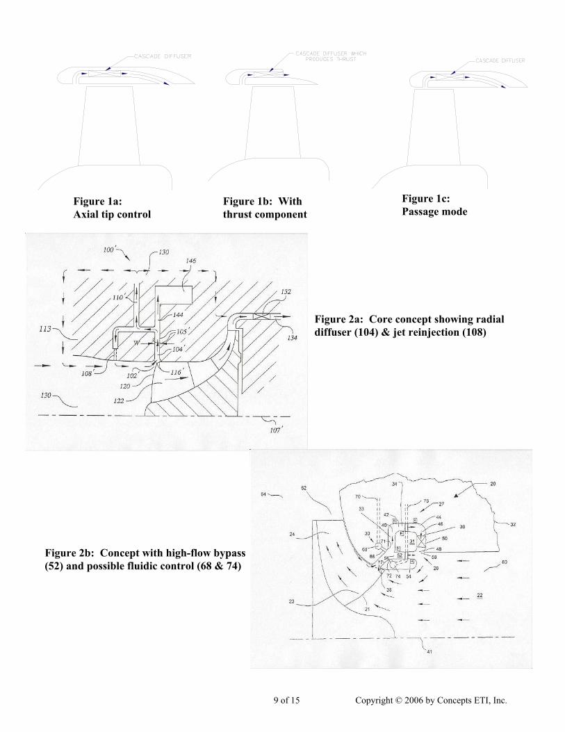
The work undertaken, to date, draws on novel ideas, which are embodied, in part, in
Figures 1 and 2. In each case, we are capturing a substantial portion of one or more of the following secondary flows: the inlet tip vortex, the tip clearance flow, and the tip or shroud line backflow or recirculating flow. In the Figure 1 cases, the high-energy vortex is harnessed so as to allow the flow to be efficiently injected downstream. Figure 2 shows some embodiments where the same flow elements are reintroduced upstream. Figure 2a illustrates another important feature of the present ideas: a vaneless diffuser allows cavitating fluid vapor to be condensed to liquid, free vortex diffusion of the highly swirling backflow, and general damping of flow fluctuations and other variants. Figure 2b stresses a simple axial bypass that allows extra flow to pass at high flow rates thus pushing off choke or early cavitation to a higher flow level. Many builds of these ideas have been successfully tested, including axial, mixed flow, and radial pumps and compressors.
2. PRINCIPAL WORKS OF OTHER INVESTIGATORS
Both the technical and the patent literature concerning stability, surge, stall, and related flow control are vast. To guide new workers in this field, there is a series of good summary or review articles including Greitzer (1980) [3], Japikse (1994, Ch. 9[4]; 1996[5] & 1997, Ch. 5[6]) and Sankar et al. (1999) [7] which cover both practical industrial issues and complex theoretical issues of dynamic instabilities, rotating stall, surge limit cycles, and so forth. This background is essential reading for a comprehensive understanding of the problem area, but is not specific to the passive control mechanism related herein. Considerable work has been conducted on rotating stall, including the contributions of Moore (Parts I-III, 1984) [8], McDougall et al. (1990) [9], Garnier et al. (1991) [10], and Day (1993) [11], to mention just a few on the axial compressor side, with another set of authors working on the radial compressor side of the problem. On the axial problem, the detailed research has led to means of active stability control as presented by Day (1993) [12], Feulner (1994) [13], Weigl et al. (1997) [14] and others. This is a very important field but it is quite different from the present study, which emphasizes passive control.
One aspect of the work on the radial compressors and pumps has been a distinctly pragmatic approach to range extension and instability suppression. A case in point is the early study of Flynn and Weber (1979) [15] where a change in blade shape changed the passage loadings and substantial additional range was obtained. Similarly, Sloteman et al. (1984) [16] used an inlet flow control device to capture the recirculating flow and return it to the main flow in a steady manner with greatly reduced vibrations. The work of Chapman (1980) [17] and Fisher (1988/1989)
[18] demonstrates a high flow bypass associated with alleviating inducer choke by allowing flow to enter the impeller passage downstream of the throat, hence, allowing a greater swallowing capacity.
Current CN successes have been based on early laboratory observations, which then led to several practical designs and consequential demonstrations of the core ideas. Goto (1993) [19]
foresaw one aspect of the present concepts and introduced a technically sound method to analytically assess his development work. Goto worked with a pump in a system with compliance so that a true surge could be established. He focused on the conditions where the first trace of inlet recirculation develops and forms into a recirculation flow ring just upstream of the impeller vane leading edges. By injecting a few jets of fluid tangentially into this backflow bubble or ring, in a direction contrary to the direction of rotation, he was able to suppress the classical head drop when operating from high to low flows, but not when tracing out the opposite. He used an early variant of the popular Dawes BTOB3D code (which has been radically enhanced since the time of Goto’s work). He calculated an upstream vorticity parameter and computed the secondary flow patterns inside the impeller. He showed a significant improvement in the impeller secondary flow patterns with improved inlet vorticity.
Finally, several additional references are worthy of mention because they impinge on some part of the stability problem. Meng and Prueger (2000) [20] outline a Rocketdyne inducer design procedure, which gives a basis for comparison to the exceptional inducer design mentioned in the work below. Tsujimoto et al. (2001) [21] reported superb work in tying the instabilities in diverse systems together and laying out the mathematical unifying foundation. Srinivasan et al. (2006) [22] studies the effect of a shock wave impinging on a recirculating flow, and Jukes et al. (2006) [23] gives an early report on using radio frequency glow discharge to create a plasma that might be used to provide some flow control.
When the technical literature is reviewed carefully, it is clear that some very good work has been performed in many institutions and some fine progress has been made. The results, however, are complex theoretical models and active control systems, and usually require considerable ancillary devices for signal detection and actuation. The present work is quite different in that it uses simple passive control means.
3. EXPERIMENTAL FACILITIES
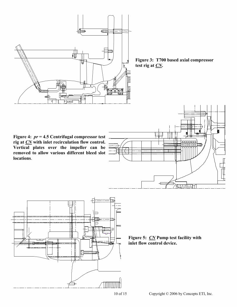
The company has three excellent test rigs, with available base stages and substantial prior test hours with each rig. Two of these rigs have been used for the work reported herein, whereas the third should be used in near-term future work to extend the present studies. These include a purely axial stage (the T700 first-stage compressor) as shown in Figure 3 below, a pr = 4.5 transonic centrifugal compressor stage as shown in Figure 4, and an axial or radial (or both) pump as shown in Figure 5. The T700 has been used on a prioran SBIR project, and the pump rig has been used on a variety of prior NASA and Air Force SBIR projects for various purposes. Bleed and jet reinjection flow control is shown in Figures 4 and 5. Key measured results are shown in the next section. All pump development testing at Concepts NREC is performed on a magnetic bearing- supported test rotor. The magnetic bearings are relatively compliant and act as very sensitive diagnostic tools. Hydraulic loads arising from incipient rotating stall, rotating cavitation, or auto-oscillation are easily observed.
4. ORIGINAL PUMP RIG TEST RESULTS
The flow control technique was shown to eliminate auto-oscillation and reduce overall pump noise and vibration levels while improving the head breakdown characteristic of a pump.
The flow control device permitted pump operation with relatively small tip clearances; this in turn increased pump efficiency and head rise. The device first tested was a simplified version of Figures 2a and 5. The device improved inducer stability and performance by removing some portion of the vapor formed by cavitation along with some portion of the secondary flow that develops at the inlet due to tip vortices, tip leakage, and shroud backflow. The kinetic energy of the secondary flows was used to condense the two-phase flow in the radial vaneless diffuser and return the flow to an appropriate point in the system. Several different variations of the basic design were investigated. Compact versions, with very tight return flow circuits requiring very little physical space, were achieved. Figures 6 & 7 show a special feature of the flow control device: by reinjecting the bleed flow upstream in different orientations, it is possible to engineer a wide variety of head flow, efficiency, and cavitation performance curves, according to a designer’s needs.
Figure 8 shows a series of early cavitation tests with and without cavitation control at three different flow coefficients using the same inducer. For all flow coefficients that exhibited auto-oscillation when no cavitation control was used, auto-oscillation was removed by the addition of the control device. With the addition of cavitation control, the head breakdown characteristic of the impeller becomes much sharper and occurs at a much lower cavitation number as compared to the corresponding characteristics without cavitation control. Additionally, because the auto-oscillation was eliminated, it was possible to operate the impeller with a tighter tip clearance and, thereby, the head rise and efficiency characteristics of the impeller were improved when cavitation control was added.
Figure 9 shows an early inducer cavitation bucket with and without cavitation control. The normalized flow coefficient is shown across the horizontal axis while the suction specific speed at 10% head breakdown is displayed on the vertical axis. Clearly, the addition of cavitation control increased the suction specific speed by approximately 10,000 over the range 0.78 < φ/φn < 1.2. With the addition of cavitation control, the region of auto-oscillation, 0.85 < φ/φn < 1.0, was eliminated.
5. RECENT TURBOPUMP TESTS WITH STABILITY CONTROL
On our most recent Air Force SBIR contract, suction performance testing was carried out at two flow coefficients. The 0.040 design point flow coefficient corresponded to a volume flow rate of 117 gpm and a 0.048 flow coefficient corresponded to a flow rate of 141 gpm. Figure 10 depicts head coefficient versus cavitation coefficient for both flow rates. Figure 11 shows the head coefficient plotted against suction specific speed for the design and high flow point cases, respectively. Figure 11 also shows the results of a suction performance repeatability test that was conducted for the design flow rate on two successive days. This demonstrated that the results are repeatable.
For both flow coefficients, the 3% breakdown head was at a suction specific speed of 75,000. In all instances, the impeller ran stably with no evidence of auto-oscillation. At the design flow coefficient, the suction specific speed was brought to 110,000 with only a 6% drop in the head coefficient. The test could not go any higher in suction specific speed because of rig limitations—the total pressure at the inlet could not be lowered any further. The high flow case
showed a 5% head drop-off at a suction specific speed of 95,000 and was still pumping stably at 129,000 with a 46% head drop-off, before the rig limit was reached.
6. COMPRESSOR TESTS
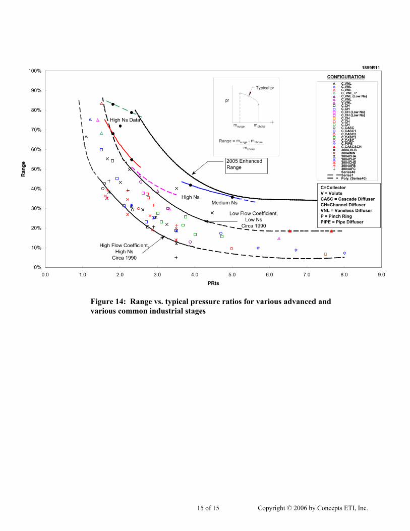
Figures 12 and 13 show a series of normalized compressor performance metrics with and without the range extension. Without the range extension technology, the compressor map was quite somewhat limited due to system surge and inducer choke. At 100% speed, the range extension technology reduced the minimum normalized flow from approximately 0.86 to 0.71 on the surge side of the map. Similar improvements in compressor range were also realized below design speed; 2% to 3% drops in pressure ratio and efficiency were observed with the application of the range control technology. The study also showed that a new diffuser should be matched to the stage when stability control is used, as the exit profiles appear to be changed and require an alternate diffuser design. Some of the efficiency loss might be recovered with a new diffuser design. Progress on range extension has been significant; a summary of some key results is given in Figure 14.
7. SUMMARY OF TESTS AND FUTURE DIRECTIONS
In total, Concepts NREC has employed nine different impellers and up to twenty-one different cover configurations with the cavitation control/stability control system. In all cases, this new technology has shown to have a significant impact on the performance of the machine. The tests have shown good regions for design optimization and also reveal some of the limits where the performance was still good, but started to deteriorate slightly. For the compressor range extension, we have both reduced the compressor’s surge flow limit and increased the compressor’s choke flow limit. The range extension technology is completely passive and has been optimized for compact installation within most compressor installations.
Continued work in this field is needed to contribute more practical devices for application in the compressor and pump markets, assuring future generation products of having wider operating range, less noise and vibration, and little or no reduction in efficiency. Already, this stability control technology gives a designer flexibility that was heretofore not available. The devices are expected to be inexpensive and reliable while offering the chance to reshape the head flow curve and the cavitation breakdown characteristic as a designer proceeds, principally by using the high flow bypass to change inlet flow states at high flow levels and jet orientation to give desired stability characteristics for low flow states.
8. ACKNOWLEDGEMENTS
The authors wish to acknowledge the National Science Foundation; Marshall Space Flight Center, NASA; and the Air Force Research Laboratories, Edwards Air Force Base for support in several demonstration phases of this work.
1. Japikse, D., Flow Stabilizing Device, Concepts ETI, Inc., U.S. Patent No. 6,699,008, Patent Filed: June 17, 2002, Date of Patent: March 2, 2004.
2. Japikse, D., and Baun, D. O., Secondary Flow Control System, Concepts ETI, Inc., U.S. Patent No. 7,025,557, Patent Filed: January 7, 2004, Date of Patent: April 11, 2006.
3. Greitzer, E. M., “Review – Axial Compressor Stall Phenomena”, ASME Journal of Fluids Engineering, June 1980, pp. 134-151.
4. Japikse, D., and Baines, N. C., Introduction to Turbomachinery, Concepts ETI, Inc., 1994, Ch. 9.
5. Japikse, D., Centrifugal Compressor Design and Performance, Concepts ETI, Inc., 1996. 6. Japikse, D., Marscher, W. D., and Furst, R. B., Centrifugal Pump Design and Performance,
Concepts ETI, Inc., 1997, Ch. 5. 7. Sankar, L. N., Prasad, J. V. R., Naumeier, Y., Haddad, W. M., Markopoulos, N., Stein, A.,
Niazi, S., and Leonessa, A., “Recent Progress in Compressor Stall and Surge Control”, 17th AIAA Applied Aerodynamics Conference, Paper No. 99-3124, Norfolk, VA, June/July 1999.
8. Moore, F. K., “A Theory of Rotating Stall of Multistage Compressors, Parts I-III”, ASME Journal of Engineering for Power, Vol. 106, 1984, pp. 313-336.
9. McDougall, N. M., Cumpsty, N. A., and Hynes, T. P., “Stall Inception in Axial Compressors”, ASME Journal of Turbomachinery, Vol. 112 , January 1990, pp. 116-125.
10. Garnier, V. H., Epstein, A. H., and Greitzer, E. M., “Rotating Waves as a Stall Inception Indication in Axial Compressors”, ASME Paper No. 90-GT-156, 1990, Journal of Turbomachinery, April 1991, pp. 290.
11. Day, I. J., “Active Suppression of Rotating Stall and Surge in Axial Compressors”, ASME Journal of Turbomachinery, Vol. 115, 1993, pp. 40-47.
12. Day, I. J., “Stall Inception in Axial Flow Compressors”, ASME Journal of Turbomachinery, Vol. 115, 1993, pp. 1-9.
13. Feulner, M. R., Hendricks, G. J., and Paduano, J. D., “Modeling for Control of Rotating Stall in High Speed Multi-Stage Axial Compressors”, ASME Turbo Expo ’94, Paper No. 94-GT-200, The Hague, Netherlands, 1994.
14. Weigl, H. J., Paduano, J. D., Frechette, L. G., Epstein, A. H., Greitzer, E. M., Bright, M. M., and Strazisar, A. J., “Active Stabilization of Rotating Stall in a Transonic Single Stage Axial Compressor”, ASME Turbo Expo ’97, Paper No. 97-GT-411, Orlando, FL, 1997.
15. Flynn, P. F., and Weber, H. G., “Design and Test of an Extremely Wide Flow Range Compressor”, ASME Paper No. 79-GT-80, 1979.
16. Sloteman, D. P., Cooper, P., and Dussourd, J. L., “Control of Backflow at the Inlets of Centrifugal Pumps and Inducers”, Proceedings of the First International Pump Symposium, Turbomachinery Laboratory, Texas A&M University, 1984, pp. 9-22.
17. Chapman, D. C., “Model 250-C30/C28B Compressor Development”, Centrifugal Compressors, Flow Phenomena and Performance, AGARD Conference Proceedings No. CP-282, 1980.
18. Fisher, F. B., “Application of Map Width Enhancement Devices to Turbocharger Compressor Stages”, SAE Paper No. 880794, Power Boost: Light, Medium and Heavy Duty Engines, SP-780, 1989.
19. Goto, A., “Suppression of Mixed-Flow Pump Instability and Surge by the Active Alteration of Impeller Secondary Flows”, ASME Paper No. 93-GT-298, 1993.
20. Meng, S. Y., and Prueger, G. H., “Validation of Inducer Design Process”, 36th AIAA/ASME/SAE/ASEE Joint Propulsion Conference, AIAA Paper No. 2000-3877, Huntsville, AL, 2000.
21. Tsujimoto, Y., Kamijo, K., and Brennen, C. E., “Unified Treatment of Flow Instabilities of Turbomachines”, AIAA Paper No. 99-2678, 1999; also Journal of Propulsion and Power, Vol. 17, No. 3, May-June 2001, pp. 636-643.
22. Srinivasan, K. R., Loth, E., and Dutton, J. C., “Aerodynamics of Recirculating Flow Control Devices for Normal Shock/Boundary-Layer Interactions”, AIAA Paper No. 2004-0426; also AIAA Journal, April 2006, pp. 751-764.
Figure 3: T700 based axial compressor test rig at CN.
Figure 4: pr = 4.5 Centrifugal compressor testrig at CN with inlet recirculation flow control.Vertical plates over the impeller can beremoved to allow various different bleed slotlocations.
Figure 5: CN Pump test facility with inlet flow control device.
0.
0.
0.
0.
0.
0
0.05
1
0.15
2
0.25
3
0.35
4
0.45
5
0.03 0.04 0.05 0.06 0.07 0.08 0.09 0.1 0.11
Inducer Flow Coefficient
Hea
d C
oeffi
cien
t
0
0.1
0.2
0.3
0.4
0.5
0.6
0.7
0.8
0.9
1
Nor
mal
ized
Effi
cien
cy (%
)
Head Build 13 (No Cavitation Contro l) Head Build 14 (Inlet Plemum - Contro l Flow to Reservo ir) Head Build 24 (Jet Reinjection - 32.5 deg. Forward) Head Build 25 (Jet Reinjection - 24.5 deg. Counter Swirl) Head Build 26 (Jet Reinjection - 24.5 deg. Preswirl) Head Build 27 (Tight Inlet Reinjection - w/ annular slo t) Head Build 28 (Tight Inlet Reinjection - w/ annular slo t)Head Build 29 Tight Inlet Reinjection - w/ extra diffuser & annular slot) Head Build 30 (Tight Inlet Reinjection - w/ extra diffuser & discrete jets) Eff. Build 13 Eff. Build 14 Eff. Build 24 Eff. Build 25 Eff. Build 26 Eff. Build 27 Eff. Build 28 Eff. Build 29 Eff. Build 30
Figure 6: Inducer (alone) total-to-static head coefficient and efficiency versus flow coefficient; the influence of setting the reinjection jet conditions is profound and affords design opportunity. Results for an early design.
Figure 7: Inducer (alone) total-to-static head coefficient versus suction specific speed showing the r.h.s. drop-off as the inducer experiences the formation of everstronger cavitation. The influence of setting the reinjection jet conditions is profound and affords design opportunity. Results for an early design.