This paper is part of the Proceedings of the 14th International Conference on Studies, Repairs and Maintenance of Heritage Architecture (STREMAH 2015) www.witconferences.com
T. Takayanagi & O. Naoyuki, Int. J. Comp. Meth. and Exp. Meas., Vol. 4, No. 2 (2016) 90–99
STABILITY EVALUATION OF MASONRY RETAINING WALLS BASED ON THE DEFORMATION RATIO OF THE
MAXIMUM HORIZONTAL DISPLACEMENT TO THE HEIGHT
TSUYOSHI TAKAYANAGI & OTA NAOYUKIGeotechnical Hazard & Risk Mitigation Disaster Prevention Technology Div, Railway Technical Research
Institute, Japan.
ABSTRACTMany masonry retaining walls which were constructed by using square pyramidal stones over 100 years ago exist on cutting-slopes in Japanese railways. In these walls, there are some arch-deformed walls that resulted from receiving external force like an earth pressure or a seismic shaking. These deformed walls have a relatively high risk of collapse in case of receiving the large external force. But the relationship between the deformation amount and the stability of the wall is unclear. For this reason, this study evaluates the threshold deformation ratio of the maximum horizontal displacement of the wall to its height for discriminating unstable masonry retaining walls by modelling tests. In the model-ling tests, we collapsed two meter-tall masonry retaining walls which are composed of 200 mm × 200 mm × 334 mm- square pyramidal stones by vertical loading applied at the top of slope, and measured earth pressure and horizontal displacement of the wall. As a result of the test, the masonry retaining wall was deformed over 4% deformation ratio by receiving the limit earth pressure against the bearing capacity. This study made it clear that old masonry retaining walls existing in Japanese railways which are deformed over 4% deformation ratio should be judged as unstable. Furthermore we developed simple reinforcement works for the deformed walls and confirmed the deformation prevention effect of those works by the modelling test.Keywords: deformation ratio, earth pressure, masonry retaining walls, modeling test, reinforcement work.
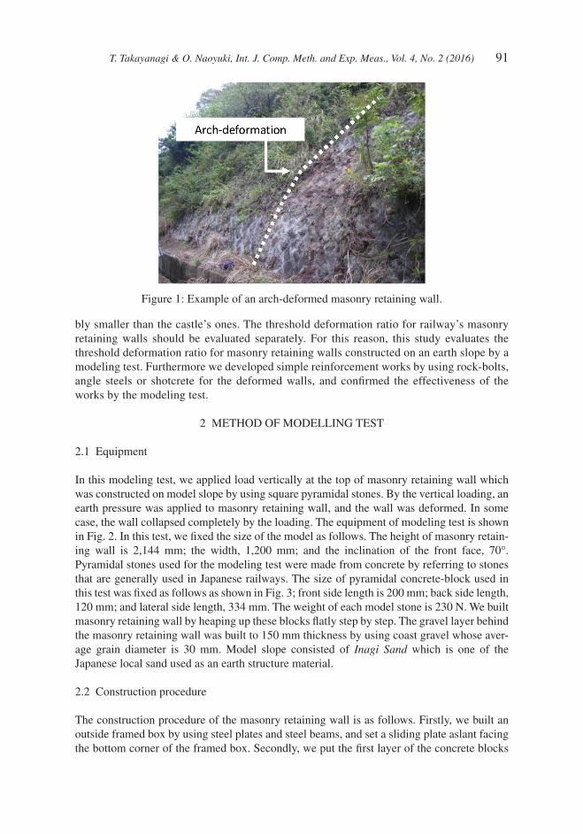
1 INTRODUCTIONMany masonry retaining walls that were constructed by using square pyramidal stones over 100 years ago exist on cutting-slopes in Japanese railways. In these masonry retaining walls, there are some arch-deformed walls which resulted from receiving external force like an earth pressure or a seismic shaking, as shown in Fig. 1. These deformed walls have a rela-tively high risk of collapse in case of receiving the large external force. The collapse becomes a threat to the train’s safety. For these reasons, Japanese railway companies make a visual inspection of earth structures like a masonry retaining wall every two years and look out extraordinary deformation. But the relationship between the deformation amount and the stability of the wall is unclear up to now.
According to the previous study about Japanese castles, deformed stonewalls whose ratio of the maximum horizontal displacement to its height is over 6% are experientially judged as unstable [1]. But stones used in railway’s masonry retaining walls are apprecia-
T. Takayanagi & O. Naoyuki, Int. J. Comp. Meth. and Exp. Meas., Vol. 4, No. 2 (2016) 91
bly smaller than the castle’s ones. The threshold deformation ratio for railway’s masonry retaining walls should be evaluated separately. For this reason, this study evaluates the threshold deformation ratio for masonry retaining walls constructed on an earth slope by a modeling test. Furthermore we developed simple reinforcement works by using rock-bolts, angle steels or shotcrete for the deformed walls, and confirmed the effectiveness of the works by the modeling test.
2 METHOD OF MODELLING TEST
2.1 Equipment
In this modeling test, we applied load vertically at the top of masonry retaining wall which was constructed on model slope by using square pyramidal stones. By the vertical loading, an earth pressure was applied to masonry retaining wall, and the wall was deformed. In some case, the wall collapsed completely by the loading. The equipment of modeling test is shown in Fig. 2. In this test, we fixed the size of the model as follows. The height of masonry retain-ing wall is 2,144 mm; the width, 1,200 mm; and the inclination of the front face, 70°. Pyramidal stones used for the modeling test were made from concrete by referring to stones that are generally used in Japanese railways. The size of pyramidal concrete-block used in this test was fixed as follows as shown in Fig. 3; front side length is 200 mm; back side length, 120 mm; and lateral side length, 334 mm. The weight of each model stone is 230 N. We built masonry retaining wall by heaping up these blocks flatly step by step. The gravel layer behind the masonry retaining wall was built to 150 mm thickness by using coast gravel whose aver-age grain diameter is 30 mm. Model slope consisted of Inagi Sand which is one of the Japanese local sand used as an earth structure material.
2.2 Construction procedure
The construction procedure of the masonry retaining wall is as follows. Firstly, we built an outside framed box by using steel plates and steel beams, and set a sliding plate aslant facing the bottom corner of the framed box. Secondly, we put the first layer of the concrete blocks
Figure 1: Example of an arch-deformed masonry retaining wall.
92 T. Takayanagi & O. Naoyuki, Int. J. Comp. Meth. and Exp. Meas., Vol. 4, No. 2 (2016)
on the bottom of the framed box, and put dry coast gravel and unsaturated sand into the framed box behind the blocks for constructing 250 mm-tall sand layer. Then water content ’w’ of the sand was adjusted so as to be the optimum water content ’wopt’. The optimum water content is 18%. Thirdly, we compacted sand layer dynamically and set several sensors in the model slope. Thus, we laid the layer of concrete- blocks, gravel, and sand. Finally, we con-structed 2,144 mm-tall masonry retaining wall by repeating the above procedures from the second to the third, and put a loading square plate whose side length is 1,100 mm and 500 mm at the top of model slope. Then ‘Nd’ resistance value of the sand layer measured by simple dynamic cone penetration test [2] was from 5 to 10.
2.3 Loading procedure
We applied an earth pressure to the masonry retaining wall through vertical loading at the top of the slope in each test case. Then a hydraulic jack with the maximum loading capacity of 200 kN was used for the loading. The vertical loading was conducted step-by-step by repeat-ing load and un-load.
Figure 2: Side view of equipments of modelling test.
Figure 3: Size of square pyramidal stone.
T. Takayanagi & O. Naoyuki, Int. J. Comp. Meth. and Exp. Meas., Vol. 4, No. 2 (2016) 93
2.4 Test condition
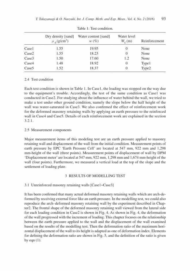
Each test condition is shown in Table 1. In Case1, the loading was stopped on the way due to the equipment’s trouble. Accordingly, the test of the same condition as Case1 was conducted in Case2. For studying about the influence of water behind the wall, we tried to make a test under other ground condition, namely the slope below the half height of the wall was water-saturated in Case3. We also confirmed the effect of reinforcement work for the deformed masonry retaining walls by applying an earth pressure to the reinforced wall in Case4 and Case5. Details of each reinforcement work are explained in the section 3.2.1.
2.5 Measurement components
Major measurement items of this modeling test are an earth pressure applied to masonry retaining wall and displacement of the wall from the initial condition. Measurement points of earth pressure by EPC ‘Earth Pressure Cell’ are located at 547 mm, 922 mm and 1,298 mm-height of the wall (three points). Measurement points of displacement of wall by DPM ‘Displacement meter’ are located at 547 mm, 922 mm, 1,298 mm and 1,674 mm-height of the wall (four points). Furthermore, we measured a vertical load at the top of the slope and the settlement of loading plate.
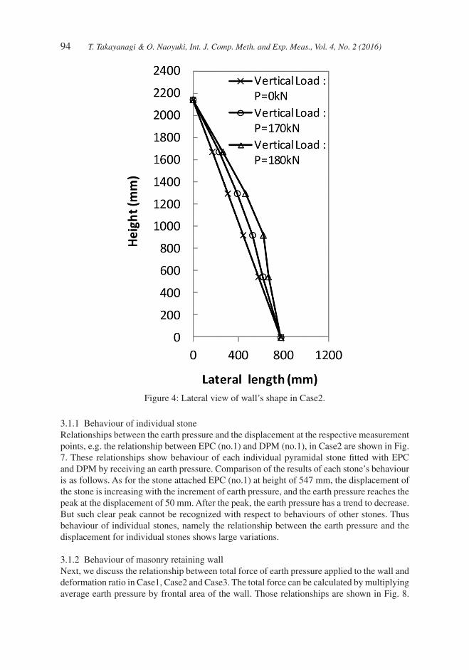
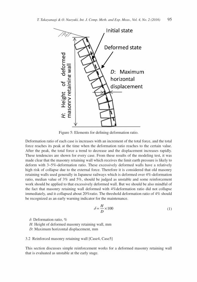
It has been confirmed that many actual deformed masonry retaining walls which are arch-de-formed by receiving external force like an earth pressure. In the modelling test, we could also reproduce the arch–deformed masonry retaining wall by the experiment described in Chap-ter2. The frontal shape of the deformed masonry retaining wall viewed from the lateral side for each loading condition in Case2 is shown in Fig. 4. As shown in Fig. 4, the deformation of the wall progressed with the increment of loading. This chapter focuses on the relationship between the earth pressure applied to the wall and the displacement of the wall examined based on the results of the modelling test. Then the deformation ratio of the maximum hori-zontal displacement of the wall to its height is adapted as one of deformation index. Elements for defining the deformation ratio are shown in Fig. 5, and the definition of the ratio is given by eqn (1).
94 T. Takayanagi & O. Naoyuki, Int. J. Comp. Meth. and Exp. Meas., Vol. 4, No. 2 (2016)
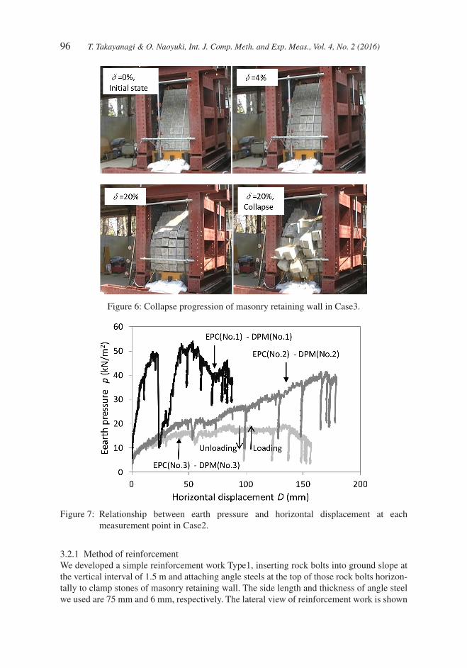
3.1.1 Behaviour of individual stoneRelationships between the earth pressure and the displacement at the respective measurement points, e.g. the relationship between EPC (no.1) and DPM (no.1), in Case2 are shown in Fig. 7. These relationships show behaviour of each individual pyramidal stone fitted with EPC and DPM by receiving an earth pressure. Comparison of the results of each stone’s behaviour is as follows. As for the stone attached EPC (no.1) at height of 547 mm, the displacement of the stone is increasing with the increment of earth pressure, and the earth pressure reaches the peak at the displacement of 50 mm. After the peak, the earth pressure has a trend to decrease. But such clear peak cannot be recognized with respect to behaviours of other stones. Thus behaviour of individual stones, namely the relationship between the earth pressure and the displacement for individual stones shows large variations.
3.1.2 Behaviour of masonry retaining wallNext, we discuss the relationship between total force of earth pressure applied to the wall and deformation ratio in Case1, Case2 and Case3. The total force can be calculated by multiplying average earth pressure by frontal area of the wall. Those relationships are shown in Fig. 8.
Figure 4: Lateral view of wall’s shape in Case2.
T. Takayanagi & O. Naoyuki, Int. J. Comp. Meth. and Exp. Meas., Vol. 4, No. 2 (2016) 95
Deformation ratio of each case is increases with an increment of the total force, and the total force reaches its peak at the time when the deformation ratio reaches to the certain value. After the peak, the total force a trend to decrease and the displacement increases rapidly. These tendencies are shown for every case. From these results of the modeling test, it was made clear that the masonry retaining wall which receives the limit earth pressure is likely to deform with 3~5%-deformation ratio. These excessively deformed walls have a relatively high risk of collapse due to the external force. Therefore it is considered that old masonry retaining walls used generally in Japanese railways which is deformed over 4%-deformation ratio, median value of 3% and 5%, should be judged as unstable and some reinforcement work should be applied to that excessively deformed wall. But we should be also mindful of the fact that masonry retaining wall deformed with 4%deformation ratio did not collapse immediately, and it collapsed about 20%ratio. The threshold deformation ratio of 4% should be recognized as an early warning indicator for the maintenance.
d = ×
H
D100 (1)
δ: Deformation ratio, %H: Height of deformed masonry retaining wall, mmD: Maximum horizontal displacement, mm
This section discusses simple reinforcement works for a deformed masonry retaining wall that is evaluated as unstable at the early stage.
Figure 5: Elements for defining deformation ratio.
96 T. Takayanagi & O. Naoyuki, Int. J. Comp. Meth. and Exp. Meas., Vol. 4, No. 2 (2016)
3.2.1 Method of reinforcementWe developed a simple reinforcement work Type1, inserting rock bolts into ground slope at the vertical interval of 1.5 m and attaching angle steels at the top of those rock bolts horizon-tally to clamp stones of masonry retaining wall. The side length and thickness of angle steel we used are 75 mm and 6 mm, respectively. The lateral view of reinforcement work is shown
Figure 6: Collapse progression of masonry retaining wall in Case3.
Figure 7: Relationship between earth pressure and horizontal displacement at each measurement point in Case2.
T. Takayanagi & O. Naoyuki, Int. J. Comp. Meth. and Exp. Meas., Vol. 4, No. 2 (2016) 97
in Fig. 9. This reinforcement work relies on the reaction force of the angle steels which is originally to be fixed at the top of the rock bolts, but insertion of those rock bolts to the ground slope was difficult by absence of specialized working machines in the modeling test. Accordingly, the reaction force of the angle steel is generated by fixing the angle to the framed box as a substitute way. In the reinforcement work of Type2, we sprayed shot-crete which was mixed with 1 vol% polypropylene fiber, on the front surface of the wall in addition to the reinforcement work of Type1. The shotcrere has the compression strength of 29 N/mm2, the elastic coefficient of 18,000 N/mm2 after 28 days curing, and the thickness of about 5 cm and was overlaid on the front surface of the wall by hand working.
3.2.2 Effect of reinforcement worksThe loading experiment to evaluate the effect to prevent the deformation of masonry retain-ing wall by those reinforcement works was conducted by the following the way explained in Chaper2. To examine the effect of those reinforcement works, a relationship between the vertical load at the top of slope and the maximum horizontal displacement of the masonry retaining wall are shown in Fig. 10. The masonry retaining wall reinforced by Type1 and Type2, could prevent large deformation as compared to the non-reinforced wall, and the rein-forced masonry retaining walls could keep the deformation ratio under 4% for 200 kN-vertical loading which generates the total force of earth pressure of about 60 kN. Rein-forcement work Type2 is more effective than type1 in preventing deformation. But it should be noted that Type2 caused disfigurement of the wall and the shotcrete was cracked around the center of wall by the earth pressure generated in this loading experiment. In this modeling test, it has been made clear that those reinforcement works have a certain effect of deforma-tion prevention. But we could not confirm the maximum bearing capacity of those reinforced masonry retaining walls by making them collapse because a shortage of jack’s capacity. However, we could confirm the effectiveness of those reinforcement works under the condition that the total force of earth pressure is under 60 kN. Therefore, it is considered that those reinforcement work should be applied under that condition.
Figure 8: Relationship between total force of earth pressure and deformation ratio with respect to un-reinforcement wall.
98 T. Takayanagi & O. Naoyuki, Int. J. Comp. Meth. and Exp. Meas., Vol. 4, No. 2 (2016)
Figure 9: Reinforcement work for masonry retaining wall.
Figure 10: Relationships between vertical load and horizontal displacement.
T. Takayanagi & O. Naoyuki, Int. J. Comp. Meth. and Exp. Meas., Vol. 4, No. 2 (2016) 99
4 CONCLUSIONSWe conducted the modeling test to confirm the effectiveness of stability evaluation method for deformed masonry retaining walls based on the deformation ratio of the maximum hori-zontal displacement of the wall to its height. As a result of the test, the masonry retaining walls generally used in Japanese railway were deformed over 4%-deformation ratio by receiving the limit earth pressure against the wall’s bearing capacity. This study made it clear that the old masonry retaining walls which are deformed with more than 4%-deformation ratio should be judged as unstable. We also developed the simple reinforcement works for the deformed walls and confirmed the deformation prevention effect of those works by the modeling test.
REFERENCES[1] Amano, K., Nishida, K., Watanabe, T., Tamano, T. & Hakamura, H., Historical and
empirical study on osaka castle masonry wall at tokugawa period. Journal of Japan Society of Civil Engineers, 2000(660), pp. 101–110, 2000.http://dx.doi.org/10.2208/jscej.2000.660_101
[2] The Japanese geotechnical society, Method for Portable Dynamic Cone Penetration Test, Japanese geotechnical society standards, JGS1433, 2012.