Page 1
Training
Loader Crane
Stabilizer intelligence
S-IQ
Version: 2018/03
Original Training Document English
PALFINGER AG
Lamprechtshausener Bundesstraße 8 5101 Bergheim | Austria
www.palfinger.com
Page 3
Contents
www.palfinger.com 3
Contents
1 General .....................................................................................................................................5
1.1 Introduction and handling of this document ...............................................................5
1.2 Validity .......................................................................................................................5
1.3 Symbols in this document ..........................................................................................5
2 System requirements ..............................................................................................................6
3 Function ...................................................................................................................................6
3.1 General ......................................................................................................................6
3.2 Graphical representation ...........................................................................................7
3.3 S-IQ Functions ...........................................................................................................8
3.3.1 S-IQ sensor positioning ..............................................................................9
3.3.2 S-IQ1 crane stabilizers ............................................................................ 10
3.3.3 S-IQ2 additional stabilizers...................................................................... 10
3.3.4 S-IQ3 frame stabilizer .............................................................................. 11
3.3.5 S-IQ3 frame stabilizer variants ................................................................ 11
3.4 CAN bus connection ............................................................................................... 13
3.5 S-IQ Option 1-3 ....................................................................................................... 14
3.6 Comfort function ..................................................................................................... 15
3.7 Mounting position .................................................................................................... 15
4 Customer benefit .................................................................................................................. 16
5 Wiring .................................................................................................................................... 16
5.1 General ................................................................................................................... 16
5.2 Terminals ................................................................................................................ 16
5.3 Safety-related functions .......................................................................................... 17
5.4 Wiring diagrams ...................................................................................................... 18
5.4.1 Wiring diagram S-IQ1 / S-IQ2 ................................................................. 18
5.4.2 Wiring diagram S-IQ1 / S-IQ3 ................................................................. 19
5.4.3 Wiring diagram S-IQ1 / S-IQ3 ................................................................. 20
6 LED status codes ................................................................................................................. 21
7 Related parts ........................................................................................................................ 22
Page 4
Contents
4 www.palfinger.com
8 PALDIAG.NET settings ........................................................................................................ 23
8.1 Main selection ......................................................................................................... 23
8.2 Setting digital sensor signals .................................................................................. 24
8.3 Setting Frame protection system (FPS) ................................................................. 25
8.4 Setting of transport and stabilizer monitoring (TRANS / ABSTW) ......................... 26
8.5 Setting (activation) of stabilizer comfort function .................................................... 27
8.6 Setting stabilizer force measurement (FSTAB) ...................................................... 28
9 PALDIAG.NET diagnostics .................................................................................................. 29
Page 5
Stabilizer intelligence General
www.palfinger.com 5
1 General
1.1 Introduction and handling of this document
This PALFINGER original training document is a technical description of systems on a loader
crane. It will be handed out at PALFINGER trainings and should serve as a reference book for
service and repair work.
This training document is mainly addressed to specialized companies and PALFINGER
service workshops. Appropriate product knowledge and basic product education is required.
1.2 Validity
This training document is valid without any time limitation for the described system.
However, it is possible, that through further developments new versions of this document could
be available. PALFINGER reserves the right to change this document at any time.
The latest version of this training document, as well as any other technical documentation, are
available from PALFINGER general representatives or online at PALDESK under Products
Service Training Documents.
The required registration can be done at www.palfinger.com.
© Copyright by PALFINGER Duplication, also in extracts, is only permitted with written permission of PALFINGER.
1.3 Symbols in this document
The following symbols and signal words are mentioned in this document:
DANGER
Situation, that will lead to death or serious injuries.
WARNING
Situation, that could lead to death or serious injuries.
CAUTION
Situation, that could lead to minor injuries.
ATTENTION
Situation, that could lead to material damage.
IMPORTANT INFORMATION
Important information for the user.
PLEASE NOTE
Information, which makes working with the unit easier.
Page 6
System requirements Stabilizer intelligence
6 www.palfinger.com
2 System requirements
PALTRONIC 150
SH and TEC
3 Function
3.1 General
The crane stabilizers and the additional stabilizers have to be electrically connected to the
crane. This requires a lot of time and precision by the professional staff. Incorrect connection
may lead to malfunctions.
The intelligent plug-and-play solution Stabilizer Intelligence S-IQ from PALFINGER simplifies
the connection of additional stabilizers and front or frame stabilizers.
In this context the following factors were focused:
avoid errors
simple troubleshooting
fast serviceability
fast replacement
The support signals are processed in an electronic control unit S-IQ and communicate with
the crane electronics by means of a CAN bus signal.
A separate electronic control unit is included per stabilizers pair. This unit can be mounted on
the standard position on the outrigger box or individually on the vehicle.
With a pre-assembled and sufficiently long cable harness, the sensors and lights of the
outrigger box and stabilizers can be connected comfortably, and especially, with a non-
confusable connection.
Page 7
Stabilizer intelligence Function
www.palfinger.com 7
Up to 6 stabilizer cylinders can be integrated into the system (2 crane stabilizers + 2 additional
stabilizers + 2 front- or frame stabilizers).
IMPORTANT INFORMATION
To fulfil safety regulations, sensors with two channels are used for safety-relevant
signals. Two channels mean, that a switch requires two separate signals (NO / NC).
The switch-over must be done within 0.8 seconds. If this is not the case, an error
occurs. A switch-over, e.g. using a relay, does not work, because a relay switches too
inaccurate.
Possible sensor signals (for one stabilizer)
Stabilizer supported (SIL2 proximity sensor)
Outrigger fully extended/HPSC-L (SIL2 proximity sensor)
Outrigger retracted: transport position/plausibility (proximity sensor)
Outrigger length measurement
(CAN open, magnetostrictive length senor or rope transducer)
Stabilizer retracted (ABSTW-ABSTW)
Stabilizer force measurement FSTAB, 2 SIL2 pressure transducers (optional)
Angle measurement X-support via CAN open slewing encoder
(possible, but not realized from the software)
Supply connections for stabilizer light
3.2 Graphical representation
The S-IQ systems are assigned to supports and labelled with S-IQ1, S-IQ2 und S-IQ3 as
shown. S-IQ1 is connected to PALTRONIC 150 via CAN sensor bus.
1 S-IQ1 crane stabilizers
2 S-IQ2 additional stabilizers
3 S-IQ3 frame stabilizers
Page 8
Function Stabilizer intelligence
8 www.palfinger.com
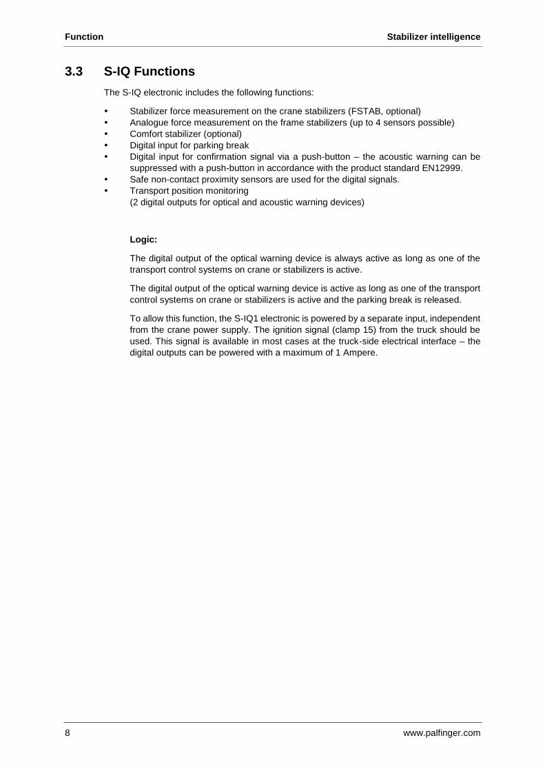
3.3 S-IQ Functions
The S-IQ electronic includes the following functions:
Stabilizer force measurement on the crane stabilizers (FSTAB, optional)
Analogue force measurement on the frame stabilizers (up to 4 sensors possible)
Comfort stabilizer (optional)
Digital input for parking break
Digital input for confirmation signal via a push-button – the acoustic warning can be
suppressed with a push-button in accordance with the product standard EN12999.
Safe non-contact proximity sensors are used for the digital signals.
Transport position monitoring
(2 digital outputs for optical and acoustic warning devices)
Logic:
The digital output of the optical warning device is always active as long as one of the
transport control systems on crane or stabilizers is active.
The digital output of the optical warning device is active as long as one of the transport
control systems on crane or stabilizers is active and the parking break is released.
To allow this function, the S-IQ1 electronic is powered by a separate input, independent
from the crane power supply. The ignition signal (clamp 15) from the truck should be
used. This signal is available in most cases at the truck-side electrical interface – the
digital outputs can be powered with a maximum of 1 Ampere.
Page 9
Stabilizer intelligence Function
www.palfinger.com 9
3.3.1 S-IQ sensor positioning
Version up to PK34002SH R4X Scanning sensor for stabilizer signals located
“above” outrigger cross beam
Example: PK10002SH with mechanical stabilizer system R2 Scanning sensor in roller support for
stabilizer signal located “underneath” on
outrigger cross beam
Version from PK42002SH Scanning sensor for stabilizer signal located “above” on outrigger cross beam (protected with plastic cap)
Scanning sensor for additional stabilizers can be mounted either “above” (1) or “underneath” (2) on the cross beam. This is an order option!
Page 10
Function Stabilizer intelligence
10 www.palfinger.com
Switch positions
Type Switch position underneath Switch position above
BS001 X --
BS002 X O
BS003 X O
BS004 X --
BS005 -- X
BS006 -- X
BS007 -- X
BS1003A O X
BS1242A-1 -- X
BS1286A X
BS1298A X
X Standard Equipment O Optional a retrofit kit is available at PPC to change from standard to opposite version
3.3.2 S-IQ1 crane stabilizers
The crane stabilizer are wired, factory connected and tested. The version of the S-IQ1 cable
harness depends on the crane equipment.
The digital input of the ballast weight LCA03 is located at the grey connector (C81) on S-IQ1
electronic box of the crane stabilizers.
3.3.3 S-IQ2 additional stabilizers
The additional stabilizers are factory installed and tested with the cable loop and S-IQ2
electronic.
In the additional stabilizers, the sensors and digital switches are built-in by factory.
The above mentioned plug-and-play solution has significantly improved installation safety and
assembly time to connect the units (crane stabilizers to additional stabilizers).
The S-IQ2 electronic box may basically be mounted individually (also on the truck frame) with
threaded holes on both side of the cross beam for the fixation.
It is important that the length of the pre-fabricated cable harnesses must not be changed.
The S-IQ2 electronic of the additional stabilizer has only one connector compared to S-IQ1
and S-IQ3 electronic.
On the other sides of the cable harness are pre-mounted connectors with sensor/connector
labeling. A manual wiring of the additional stabilizers is not necessary anymore (avoid errors).
The electric connection to the crane stabilizer is carried out with a pre-fabricated 5 meter
connection cable. If the cable is too short it can be extended by another 5 meter cable – this
cable kit must be ordered separately at the spare parts center.
Page 11
Stabilizer intelligence Function
www.palfinger.com 11
3.3.4 S-IQ3 frame stabilizer
Like for the additional stabilizers, the frame stabilizers will be delivered as kit.
The S-IQ3 electronic box has 2 connections. The second plug (grey) is prepared to take
pressure transducer signals.
The digital inputs for ballast weight LCA05 and LCA06 are also included in the S-IQ3 electronic
(Connector C90 blue).
3.3.5 S-IQ3 frame stabilizer variants
The PIN assignment is different depending on frame stabilizer variant. This is important on
variants with rear stabilizer and rear hatch (quadrant C).
The exact assignment can be found at crane related wiring diagrams.
crane stabilizers
S-IQ1
Connector C80 (blue)
B758
B760
Connector C81 (grey)
U330
U331
U332
U333
crane and additional stabilizers
S-IQ1 S-IQ2
Connector C85 (blue)
B770
B772
1x front stabilizer
S-IQ1 S-IQ2 S-IQ3
Connector C90 (blue)
B730
Connector C91 (grey)
U334
U335
Page 12
Function Stabilizer intelligence
12 www.palfinger.com
2x front stabilizers
S-IQ1 S-IQ2 S-IQ3
Connector C90 (blue)
B730
B732
Connector C91 (grey)
U334
U335
U326
U327
1x rear stabilizer
S-IQ1 S-IQ2 S-IQ3
Connector C90 (blue)
B744
Connector C91 (grey)
U336
U337
2x rear stabilizers
S-IQ1 S-IQ2 S-IQ3
Connector C90 (blue)
B744
B746
Connector C91 (grey)
U336
U337
U328
U329
1x front stabilizer
1x rear stabilizer with rear hatch
PK200002L-SH
S-IQ1 S-IQ2 S-IQ3
Connector C90 (blue)
B728
B740
B744
Connector C91 (grey)
U334
U335
U336
U337
1x front stabilizer with outrigger
1x rear stabilizer
S-IQ1 S-IQ2 S-IQ3
Connector C90 (blue)
B724
B730
B744
Connector C91 (grey)
U334
U335
U336
U337
Page 13
Stabilizer intelligence Function
www.palfinger.com 13
3.4 CAN bus connection
1 S-IQ1 (is directly connected to X5-Box)
Connector C80 blue PIN 15/29 Connection to X5 (Sensor-Bus)
Connector C81 grey PIN 23/37 Connection to S-IQ2
2 S-IQ2 (is connected to S-IQ1 via CAN-Bus)
Connector C85 blue PIN 15/29 Connection to S-IQ1
3 S-IQ3 (is directly connected to X5-Box)
Connector C90 blue PIN 15/29 Connection to X5 (Sensor-Bus)
More detailed information regarding S-IQ is available at PALDESK:
Topic Location
Connection PALDESK crane related wiring diagrams
S-IQ Overview PALDESK Products Service Training Documents
Crane C-62 S-IQ Overview
S-IQ Harness variants PALDESK Products Service Loader Crane EMEA
Service Bulletins 2017 S-IQ Harness variants
Page 14
Function Stabilizer intelligence
14 www.palfinger.com
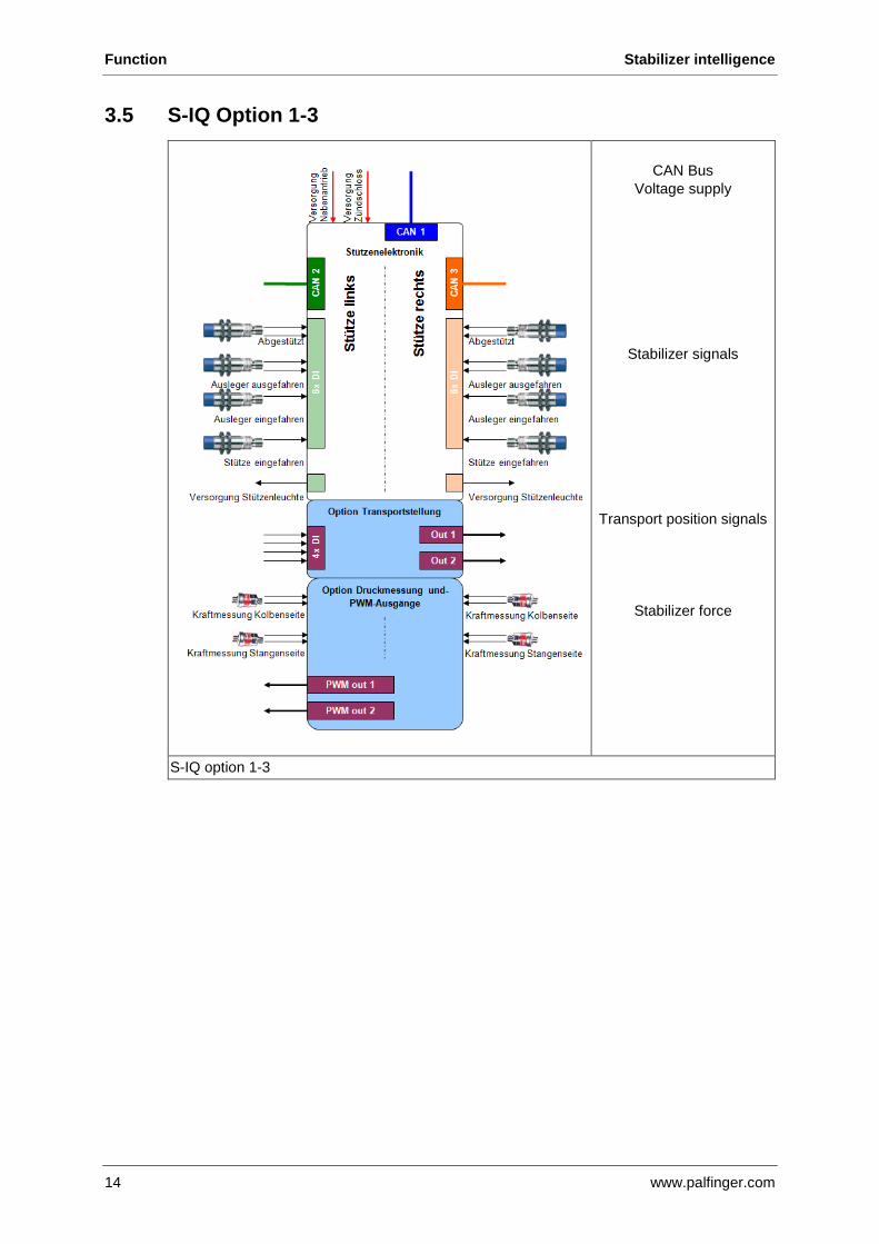
3.5 S-IQ Option 1-3
CAN Bus
Voltage supply
Stabilizer signals
Transport position signals
Stabilizer force
S-IQ option 1-3
Page 15
Stabilizer intelligence Function
www.palfinger.com 15
3.6 Comfort function
With the comfort function for stabilizers, the system switches off briefly when the stabilizer gets
in contact with ground and an acoustic signal is heard. Further stabilizer movement is possible
after lever neutral position (RRC).
Central connector Electronic unit BS-standard position
3.7 Mounting position
The roller switch for outrigger monitoring on the underside of the outrigger box was replaced
by a non-contact proximity sensor. This allows the sensor to be mounted on the upper or
underside of the outrigger box.
The mounting position of the additional stabilizers must be stated when ordering (MTF-A or
MTF-B) so that the proximity sensor is mounted on the upper or underside of the outrigger
box.
Subsequent repositioning of the sensor is possible and it can be modified in PALDIAG.NET.
Proximity sensor 1 Sensor position upperside (MTF-B)
2 Sensor position underside (MTF-A)
Page 16
Customer benefit Stabilizer intelligence
16 www.palfinger.com
4 Customer benefit
S-IQ contributes to the further improvement of the interface to the crane, and the acceleration
of mounting the additional stabilizers.
S-IQ brings the following benefits:
Massive reduction of assembly time and thus assembly costs
Pre-assembled cable harness (plug-and-play)
Error-free connection of the additional stabilizers to the crane
Better protection of outrigger monitoring switches thanks to optimized switch position
Integration of the stabilizer sensor system into the CAN bus system of the crane,
therefore directly processing the signals.
Additional stabilizers pluggable
Functional enhancements “Transport position”
Comfort function (optional)
Function HPSC-Plus LOAD (optional)
5 Wiring
5.1 General
With the S-IQ system, the physical structure of the CAN sensor bus has changed basically.
Newly developed CAN participants as well as digital sensors are used.
The new sensors for the length measurement have fixed addresses at the S-IQ units.
Addressing by wire is no longer required. Also the digital input extension is eliminated.
Every unit (crane stabilizer, additional stabilizer, frame stabilizer) got its own S-IQ
electronic unit.
The S-IQ system was developed as a plug-and-play solution.
Retrofit to S-IQ is not possible.
The S-IQ electronic units are protected with 5 A (F175) fuses by factory.
5.2 Terminals
Terminal: Name: Technical description:
851 Uzs IN Truck plus terminal via ignition ON, cl. 15 (superstructure interface)
800 GND Truck minus terminal 31 (superstructure interface)
175 Upto Truck PTO ON (superstructure interface)
650 CAN LO CAN connection from S-IQ1 to Paltronic
651 CAN HO CAN connection from S-IQ1 to Paltronic
653 CAN L1 CAN connection from S-IQ1 to S-IQ3
654 CAN H1 CAN connection from S-IQ1 to S-IQ3
401 Trans2 Main boom digital input
790 DI Input Digital signal of parking brake
792 DI Input Digital signal of acknowledgement key
794 DI OUT Digital signal, acoustic output max. 1A
796 DI OUT Digital signal, visual output max. 1A
Page 17
Stabilizer intelligence Wiring
www.palfinger.com 17
5.3 Safety-related functions
For a CE-conform design the following signals have to be indicated by an optical and
acoustical alarm in the driver’s cab.
Transport position monitoring of the boom-system (e.g. TRAN1, TRAN2)
The transport position monitoring checks if the boom-system of the crane is in transport
position or in the arm support during travel. The improper position of the boom-system
is indicated by visual and audible signals in the driver’s cab.
Transport position monitoring of the outrigger (e.g. AUSW, AUSVW, ABSTW)
The transport position monitoring checks that - when the vehicle is in driving mode - the
outriggers are completely retracted. If this is not the case, visual and audible warnings
will be given in the cab.
On cranes with S-IQ the visual and audible warnings of all transport position monitoring
units are interconnected accordingly in the S-IQ electronics and get output as digital
signals. Furthermore, the signals permitted in the loader crane standard EN 12999 can
be interlinked for suppressing the audible warning:
Signal number: Meaning: Description:
790 Parking brake engaged
Digital input on crane:
A High signal in this line means that the
parking brake of the vehicle is engaged
and the audible warning can be
suppressed.
792 Acknowledge button in the
driver's cab
Digital input on crane:
A High signal in this line suppresses the
audible warning until the status changes
the next time (acknowledge the audible
warning).
794 Audible warning
max. 1 Ampere
Digital output on crane:
The audible warning in the cab is
connected to this output (can be
acknowledged and suppressed by parking
brake).
796 Visual warning
max. 1 Ampere
Digital output on crane:
The visual warning in the cab is
connected to this output. This signal
cannot be suppressed.
PLEASE NOTE
The cables in the vehicle’s cab must be laid in compliance with the
manufacturer’s installation instructions.
Page 18
Wiring Stabilizer intelligence
18 www.palfinger.com
5.4 Wiring diagrams
5.4.1 Wiring diagram S-IQ1 / S-IQ2
S-IQ1 crane stabilizer
S-IQ2 additional stabilizers
S-IQ1 LCA03
SteckverbindungConnector
Klemmkasten X5Connection box X5
LCA03
SteckverbindungConnector
SteckverbindungConnector
Verlängerungskabel EEA13390
Extension cable EEA13390
5m
SteckverbindungConnector
SteckverbindungConnector
SteckverbindungConnector
Ste
ckverb
indung
Connecto
rSte
ckverb
indung
Connecto
r
1m
1m
Kran S-IQ1Crane S-IQ1
Zusatzabstützung S-IQ2Additional Stabilizer S-IQ2
10m
C83
GrauGrey
BlauBlue
C83
Optional
Page 19
Stabilizer intelligence Wiring
www.palfinger.com 19
5.4.2 Wiring diagram S-IQ1 / S-IQ3
S-IQ1 crane stabilizer
S-IQ1 LCA03
S-IQ3 frame stabilizer
S-IQ3 LCA05 / 06
S-IQ2 additional stabilizers
Klemmkasten X5Connection box X5
LCA03
SteckverbindungConnector
SteckverbindungConnector
Ste
ckve
rbin
dung
Connecto
rS
teckve
rbin
dung
Connecto
r
1m
1m
Kran S-IQ1Crane S-IQ1
Rahmenstützen S-IQ3Frame Stabilizer S-IQ3
GrauGrey
BlauBlue
SteckverbindungConnector
SteckverbindungConnector
SteckverbindungConnector
C93
1m
EEA13464Verbindungskabel S-IQ3connection cable S-IQ3
10m
Ste
ckv
erb
indung
Co
nnecto
r
Ste
ckverb
indung
Con
necto
r
LCA05 / 06
10m
SteckverbindungConnector
10m
C83
Zusatzabstützung S-IQ2Additional Stabilizer S-IQ2
Page 20
Wiring Stabilizer intelligence
20 www.palfinger.com
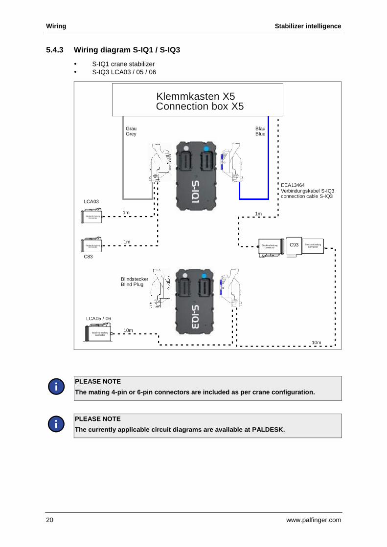
5.4.3 Wiring diagram S-IQ1 / S-IQ3
S-IQ1 crane stabilizer
S-IQ3 LCA03 / 05 / 06
PLEASE NOTE
The mating 4-pin or 6-pin connectors are included as per crane configuration.
PLEASE NOTE
The currently applicable circuit diagrams are available at PALDESK.
SteckverbindungConnector
SteckverbindungConnector
SteckverbindungConnector
C93
GrauGrey
BlauBlue
1m
10m
SteckverbindungConnector
SteckverbindungConnector
LCA05 / 06
10m
SteckverbindungConnector
SteckverbindungConnector
BlindsteckerBlind Plug
SteckverbindungConnector
SteckverbindungConnector
LCA03
1m
1m
EEA13464Verbindungskabel S-IQ3connection cable S-IQ3
C83
Klemmkasten X5Connection box X5
Page 21
Stabilizer intelligence LED status codes
www.palfinger.com 21
6 LED status codes
Different colour and flashing codes show information about the current status of the S-IQ
electronic unit.
Colour- / Flashcode Meaning Procedure
Slow flashing green.
2,5 seconds on
50 milliseconds off
OK
No error
Normal operation
Slow flashing orange.
2,5 seconds on
50 milliseconds off
CAN
communication
error
Check wiring
Fast flashing green.
Flashing in 0.5 seconds cycle
General
(internal) error
Check error codes with
PALDIAG.NET and
take appropriate steps,
possible replacement
of electronics
Fast flashing orange.
Flashing in 0.5 seconds cycle
Parameterization
error
Check error codes with
PALDIAG.NET and
take appropriate steps,
possible replacement
of electronics
Fast flashing alternating green and orange.
Flashing in 0.5 seconds cycle
Unit is in
bootloader mode
Hardware reset,
download valid
application
PLEASE NOTE
Troubleshooting should always start with checking error codes, as these information
is transmitted to PALTRONIC.
Due to its construction, the S-IQ electronic units are usually not visible from outside.
Page 22
Related parts Stabilizer intelligence
22 www.palfinger.com
7 Related parts
Pressure transducer
Inductive switch
SIL2 Inductive switch
Cable connector
(blue, grey)
Length measurement
outrigger (CAN bus)
Stabilizer light
Page 23
Stabilizer intelligence PALDIAG.NET settings
www.palfinger.com 23
8 PALDIAG.NET settings
PALDIAG.NET settings are required for the connection of S-IQ crane stabilizers and additional
stabilizers to PALTRONIC 150.
8.1 Main selection
After PALDIAG.NET login, the settings can be done via various buttons.
1 Frame protection system (FPS)
2 Monitoring transport position/comfort function (Trans / ABSTW)
3 Stabilizer force measurement (FSTAB)
4 I/O assignment
Page 24
PALDIAG.NET settings Stabilizer intelligence
24 www.palfinger.com
8.2 Setting digital sensor signals
Sensors with two channels are used with new stabilizer architecture. An invert of the signal
can be done now.
This is necessary, when sensor for signal “supported” is mounted on the lower side of the
outrigger. The configuration of all stabilizers delivered by PALFINGER is done automatically
at selection.
1 Selection of the stabilizer
2 Selection signal supported
3 Selection signal 100 % extended
4 Settings for crane stabilizers
5 Settings for additional stabilizers
6 Settings for frame stabilizers
7 Settings for ballast weights
Page 25
Stabilizer intelligence PALDIAG.NET settings
www.palfinger.com 25
8.3 Setting Frame protection system (FPS)
The new S-IQ system allows monitoring of frame stabilizer via pressure sensors and therefore
a more detailed overload detection.
Up to 2 frame stabilizers can be monitored with S-IQ. A permitted overload value has to be
defined due to existing bodybuilding. Cylinder values are filled in automatically at use of a
PALFINGER cylinder. When unknown cylinders are used, this data has to be determined out
of technical data sheets.
1 Frame stabilizer
2 Maximum allowed stabilizer force
3 Inner diameter cylinder
4 Rod diameter
Page 26
PALDIAG.NET settings Stabilizer intelligence
26 www.palfinger.com
8.4 Setting of transport and stabilizer monitoring
(TRANS / ABSTW)
The S-IQ electronic units are power supplied at normal vehicle operation for output of signals
during driving.
The following signals are available separately as DOUT on electronic unit S-IQ1:
Optical signal
Acoustic warning (can be cancelled)
1 Transport position outrigger and stabilizer active or not active for quadrant A
2 Transport position crane (Trans1, Trans2)
3 Transport position outrigger and stabilizer active or not active for quadrant D
4 Initialization (submit data to crane control system)
5 Selection of frame stabilizer configuration (see table below)
6 Transport position outrigger and stabilizer active or not active for quadrant C
7 Comfort function active or not active
8 Transport position outrigger and stabilizer active or not active for quadrant B
Frame stabilizer configuration Color Checkbox
1 front stabilizer and 1 rear stabilizer blue Frame stabilizer 1 = front
Frame stabilizer 2 = rear
2 front stabilizer yellow Frame stabilizer 1 = left
Frame stabilizer 2 = right
2 rear stabilizer purple Frame stabilizer 1 = left
Frame stabilizer 2 = right
1 rear hatch orange Frame stabilizer 1 = rear hatch
Page 27
Stabilizer intelligence PALDIAG.NET settings
www.palfinger.com 27
8.5 Setting (activation) of stabilizer comfort function
The comfort function stops the stabilizer movement at ground contact automatically.
Depending on lever movement or rather extending speed, the stabilizer continues to run
further more or less. Further movement of stabilizer is possible after lever neutral position
(RRC).
Stabilizer comfort function
Page 28
PALDIAG.NET settings Stabilizer intelligence
28 www.palfinger.com
8.6 Setting stabilizer force measurement (FSTAB)
The product standard EN12999 regulates, that all components of a loader crane must be
monitored by the overload protection. Also the crane base and the support must be monitored.
These components are highly stressed by stabilizer forces. Pressure transducers, positioned
in the stabilizers, measure the current pressure at the stabilizer cylinders.
The new S-IQ system allows monitoring of stabilizer pressure via sensors and therefore a
more detailed overload detection.
All values such as allowed overload values and cylinder diameters are loaded via PACWeb.
Due to the force transmission, stabilizer force measurement is only necessary for the crane
stabilizer cylinders. The mask is for information mainly. Changes are necessary at special
cases or at retrofit action only.
PLEASE NOTE
Stabilizer force measurement (FSTAB) must be activated in PALDIAG.NET via Plus-
Button.
The activation must be done after HPSC setting process (HPSC is active) but before
the verification process.
1 Stabilizer overload A
2 Legend
3 Stabilizer overload B
Page 29
Stabilizer intelligence PALDIAG.NET diagnostics
www.palfinger.com 29
9 PALDIAG.NET diagnostics
PLEASE NOTE
It is not allowed to open the S-IQ electronic units!
Opening results in loss of warranty!
Hardware diagnostics is limited to PALDIAG.NET diagnostics.
Active digital signals are displayed with a green LED. Analogue pressure values are converted
into bar and displayed.
PALDIAG.NET diagnostics
1 S-IQ1
2 S-IQ2
3 S-IQ3
Page 30
PALDIAG.NET diagnostics Stabilizer intelligence
30 www.palfinger.com
Signal colors:
Active signals are displayed with a green spot.
Grey spot, if no signal or not used.
Analogue signals are displayed with a yellow spot.
Power supply: red spot for plus (+) and blue spot for minus (-)
S-IQ 1 PALDIAG.NET diagnostics, connector blue and grey
S-IQ 2 PALDIAG.NET diagnostics, connector blue
Page 31
Stabilizer intelligence PALDIAG.NET diagnostics
www.palfinger.com 31
S-IQ PALDIAG.NET diagnostics, connector blue and grey