TRANSACTIONS OF THE SOCIETY OF RHEOLOGY 13:3, 291-313 (1969) Stable and Unstable Crack Growth in Viscoelastic Media W. G. KNAUSS, Firestone Flight Sciences Laboratory, Graduate Aeronautical Laboratories, California Institute Technology, Pasadena, California 91109 The problem of failure of load-bearing structures by fracture is generally important in all phases of our society. It may concern small household items as well as expensive structures of civil or space applications and accordingly may cause varying degrees of economic distress. While the state of failure is usually easily determined as either “not failed” or “completely failed,” the estimation of how close to either state a structure is, poses a much more difficult problem. It is important to recognize, however, that from an engineering point of view, the latter problem is the important one because it would allow, in principle, the prediction of the conditions leading to fracture and thus to a close estimate of the service life of a struc- ture. Inasmuch as failures by fracture involve the growth of cracks it appears that keeping track of the size of a crack in a particular structure provides a means of assessing quantitativelythe strength prior to complete failure. If one agrees that the description of structural strength is rationalized in terms of the size of defects, it follows that one must attempt to understand the laws that govern the growth of such defects in order to predict complete failure. Fracture of materials is a complicated process which encompasses atom&tic aspects, as well as microscopic and large-scale continuum mechanical considerations. Although one of these aspects should not be considered without the other we shall be concerned in the following primarily with the continuum-mechanical formulation of the problem of fracture growth in viscoelastic materials. From this 291
Transcript
TRANSACTIONS OF THE SOCIETY OF RHEOLOGY 13:3, 291-313 (1969)
Stable and Unstable Crack Growth
in Viscoelastic Media
W. G. KNAUSS, Firestone Flight Sciences Laboratory, Graduate Aeronautical Laboratories, California Institute Technology,
Pasadena, California 91109
The problem of failure of load-bearing structures by fracture is generally important in all phases of our society. It may concern small household items as well as expensive structures of civil or space applications and accordingly may cause varying degrees of economic distress. While the state of failure is usually easily determined as either “not failed” or “completely failed,” the estimation of how close to either state a structure is, poses a much more difficult problem. It is important to recognize, however, that from an engineering point of view, the latter problem is the important one because it would allow, in principle, the prediction of the conditions leading to fracture and thus to a close estimate of the service life of a struc- ture.
Inasmuch as failures by fracture involve the growth of cracks it appears that keeping track of the size of a crack in a particular structure provides a means of assessing quantitativelythe strength prior to complete failure. If one agrees that the description of structural strength is rationalized in terms of the size of defects, it follows that one must attempt to understand the laws that govern the growth of such defects in order to predict complete failure.
Fracture of materials is a complicated process which encompasses atom&tic aspects, as well as microscopic and large-scale continuum mechanical considerations. Although one of these aspects should not be considered without the other we shall be concerned in the following primarily with the continuum-mechanical formulation of the problem of fracture growth in viscoelastic materials. From this
291
292 W. G. KNAUSS
viewpoint the prediction of failure comprises three phases: first an examination of the physical situation presented by a static or growing defect in a material, second the translation of this physically observ- able situation into a mathematical model which is amenable to analysis by currently available or extendable tools of mathematics, third the theoretical exploitation of the mathematical model in an attempt to predict the behavior of defects under load and the com- parison of these results with experimentally observable phenomena to assess the validity of the modelling process as given from phase one and phase two.
While there are many important details that have bearing on such a development we shall be concerned more with the principles of the analysis and show how the various considerations of the three phases enter into the overall structure of the crack propagation problem. In keeping analytic work as simple as possible it is intended to emphasize what type of results may be obtained with the aid of continuum mechanics and where continuum mechanics requires support by microscopic considerations.
In speaking about the development and progress of fracture one needs to be constantly aware of how much detail one wishes to take into account in the description of fracture processes. Continuum mechanics is in a position to deal with very fine geometric details; taking the more ordered structure of metals rather than polymers as a guide, one woult feel confident in analyzing geometric details on the order of 100 A by the methods zf continuum mechanics while details of molecular dimensions 2-5 A are clearly beyond the scope of continuum mechanics. Since the fracture process involves the molecular structure of a material there exists a gap between the description of failure at the molecular level and that of continuum mechanics which gap can be filled, in principle, only by atomistic or molecular physics. This shortcoming makes itself felt in trying to decide how to describe the beginning or propagation of fracture in terms of continuum-mechanical language. While the molecular physicist would describe local rupture in terms of the rupture of one or a few chemical bonds, such a conceptually-though by no means factually--simple criterion is not available to the continuum mecha-
STABLE AND UNSTABLE CRACK GROWTH 293
nician who may at most speak of rupture when a bundle of polymer chains ruptures or when an agglomerate of polymer chains at the tip of a crack loses its load-bearing capacity by excessive flow or any other disintegration process.
To elucidate further the uncertainties in describing the state of fracture let us consider the initial stages of fracture growth or failure initiation. It is easy to show that calculations of material strength based on regular arrangements of the atomistic structure and on the molecular strength of the material predict much higher strength than is observed in the tests.‘*2 As a consequence, one postulates the existence of flaws which act as stress raisers and that fracture starts from the surface of such flaws. While this concept explains the dis- crepancy between the simple strength theory and observed material response in bulk, it does not clarify how fracture starts at the flaw surface nor does it establish more than an upper bound on the strength in case the geometry of the defect is identified.3
Figure 1 shows a series of possible defects which may lead to fracture. If one inspects the boundaries of a surface flaw or hole with sufficient magnification so that one will find smooth surfaces, it is probably extremely difficult to detect when that defect-surface is undergoing fracture because many phenomena will be observed which are not commonly and not easily related to gross fracture. Indeed, from a continuum-mechanics viewpoint, this situation is very much like that of viewing a large free surface, such as one side of a sheet, which is under tensile stress and undergoing fracture. The same is true with respect to fracture at interfaces between a matrix material and an inclusion. The problem is, basically, that the de- scription of the microscopic failure process to be observed in the surface of such a minute flaw is not within the scope of continuum mechanics and one must therefore postulate the existence of some kind of parameter or criterion for continuum mechanics which sup- plants the description of the detailed processes. This parameter may be a critical strain or stress4-s or energy parameter associated with the creation of new surface.g-‘3
A similarly hazy state of affairs exists with respect to failure initiation from an apparent continuum without the existence of voids or inclusions. For polymers one may envision such failure to start in regions of low molecular density or low crosslink density.14
294 W. G. KNAUSS
\ I2Jh
SURFACEFLAW
DENSITYVARIATION
4i@/INCLUSION 8
HOLE INTERFACE
CRAZE,CRACK
Fig. 1. Various types of defects leading to fracture.
This mode of failure initiation may be simulated by loading a fibrousmaterial with random fiber orientation such as Scotch DustingFabric. The random structure of this macroscopic network mayserve as an analog to the molecular network of a polymer. Figure 2shows a photographic sequence of how a defect develops in thisnetwork. Although the final defect can be reasonably well identified
Fig. 2. Sequence of defect development in a twodimensional polymer-networkmodel (Scotch dusting fabric). Numbers indicat)e amount of strain.
STABLE AND UNSTABLE CRACK GROWTH 295
with respect to shape and size such identification is virtually impos-sible in the earlier stages. In terms of continuum mechanics a defectmay or may not exist.
In passing, an interesting observation can be made with regard tothis simple experiment. In order to induce failure in the centralportion of the sheet, primarily for photographic purposes, the spotwhere failure occurred was wetted with carbon tetrachloride whichdissolved the glue holding the fibers together. In this manner theanalog network was locally reduced to an uncrosslinked polymerwhich acted as a precipitator of failure.
Returning to the lack of geometric definition of possible defectsone notes also that similar uncertainties exist with respect to thedefinition of a defect boundary on a larger scale. Figure 3 depictsthe boundary of a slowly growing crack. The ligaments usuallyadhere to the crack front and separate by thinning-out in the central
Fig. 3. Close-up view of advancing crack tip in polybutadiene acylic acid(about 20 X magnification).
206 W. U. KNAUSS
section, and contract thereafter to form irregularly shaped ballswhich give the resulting fracture surface its rough appearance. Itappears that the governing factor in crack propagation is the ma-terial disintegration into ligament form or smaller geometries andthe subsequent rheology of the disintegrated material. It is quiteobvious upon observing the material at the crack tip under a micro-scope that the disintegrating ligaments provide some cohesive forceat the tip of the crack and might have to be considered in some wayin a model of crack propagation. From the standpoint of continuummechanics the detailed treatment of even this macroscopic processis of forbidding complexity and can be incorporated into a theoryonly in an average sense.
There is another phenomenon associated with crack propagationwhich may occur in some metals and hard polymers exhibitingelastic-plastic flow behavior. An illustration of this possibility is
Fig. 4. Crack tip appearance in polypropylene (0.01 in. thick). Numbers indi-cate amount of st,rain.
STABLE ANI) UNSTABLE CRACK (:HOWTH 297
given in Figure 4 which shows the formation of a wedge shaped zone of yielded material in a sheet of unoriented polypropylene. This phenomenon is similar to that observed in materials forming crazesI which process seems to be associated with a more or less pronounced .vield stress.16 Suggested as a model to account for yielding in crack propagation processes by Brace and AlacKenzie and observed in mild steel,rs this geometry is probably most easily cast into a model of continuum mechanics of any of the crack configurations to be ob- served. In passing it is interesting to note that the boundaries of the plastic wedge seem to retain similarity as the strain increases until general yield occurs.
In summarizing these observations on the physical aspects of defects, we note that two thoughts predominate: first, that it is virtually impossible to retain in any continuum analysis the details of the defect geometries and, second, that it is equally impossible to incorporate the details of the fracture process at the tip of a growing defect. If one draws the consequences from these notions, one must by necessity think in terms of gross approximations. As a corollary, one should not expect to replicate or model the details of the fracture process to a finer degree than these approximations allow. Molecular and continuum mechanical models of fracture are, strictly speaking, incompatible, and if molecular concepts are incorporated into a continuum model, then these molecular concepts may be merely atomistic substitutes for undefined microscopic, nonatomistic mechanisms.16Jg
Stress Analysis of Defects
The primary tool in estimating the forces which act in the vicinity of defects contained in a strained solid is embodied in the theory of continuum mechanics. Basic to the developments of this branch of mechanics is the notion of the material as a mathematical continuum. This notion breaks down, of course, at the atomistic level and causes some conceptional difficulties, particularly where void formation and local material disintegration occurs, such as at the tip of an advancing crack. However, if the dimensions of the geometry under con- sideration, say, the crack, are large compared to the locally produced voids (at the tip of the crack), then it will only be necessary to define local average properties of the material to effect a stress analysis of what would now be an inhomogeneous continuum.
298 W. G. KNAUSS
The continuum postulate engenders the notions of a stress (tensor) and of continuous deformations or strain (tensor). The basic physical laws governing the motions of a continuum are Newton’s laws of motion and the laws of thermodynamics. The properties of a continuum solid are particularized through constitutive laws (stress-strain equations) which may be classified broadly as bearing dissipative (viscoelastic, plastic) and nondissipative (elastic) char- acter. The mathematical set of equations may be linear or non- linear, the nonlinearity deriving from considerations of large de- formations (kinematic nonlinearities) or nonlinear constitutive be- havior or both. A well-posed problem in continuum analysis requires the prescription of the geometry of a solid and of the forces acting on its surface in the deformed state or of displacements of the boundaries of the solid.
From the discussions in the previous section it is clear that there is no universally applicable geometry for defects. One is therefore forced to choose a representative geometry. The geometry most normally adopted is that of an ellipse (in planar geometries) or ellipsoid (in three dimensions) with the circle or sphere as one limit case and the line or penny-shaped crack as another.
Although the stress analysis of such void geometries is no mathe- matical triviality for small deformations and linear constitutive material behavior, the treatment of the problem within the frame- work of the theory of linear elasticity and viscoelasticity is reasonably well understood when compared to that treatment necessary when kinematic and/or consititutive nonlinearities dominate the problem. There are indications, although limited at this time, that for two- dimensional problems nonlinear effects (as those associated with polymers) cause relatively little deviation from the linear elasticity solutions, at least to the extent that the character of the solution does not change altogether completely.2°-22 One might hope there- fore that the results of the accessible, small deformation theories are at least useful guides to the estimation of stress distribution around defects. We shall show in the next section how the results of the linear theory may be usefully employed without it being necessary to calculate precisely the stress distribution around a defect.
Before proceeding to that point it is appropriate to review the results which the linear theory of elasticity provides with regard to fracture mechanics. Because fracture is usually associated with line
STABLE AND UNSTABLE CRACK GROWTH 299
cry = y f, (e) + 0 (1)
frx =yf2’e,+oci,
T”y = y g&v + O(l)
Fig. 5. Geometry of infinite sheet containing a finite crack.
cracks (in the undeformed or unloaded state) let us restrict our considerations to this type of crack geometry, although this restric- tion is rather arbitrary in the light of the comments in the previous section. For our purposes it sufhcies to consider the stress distribu- tion in the immediate vicinity of the crack tip. The two-dimensional analysis of a crack shows *3~*4 that the stresses at the tip of the crack are unbounded as the tip is approached as
where the coordinates r and 0 are as shown in Figure 5 and K depends on the geometry and loading of the external boundary.*
* If the sheet is infinite in the z and ?/ direction and the load is in the y direction only, then
K = P/-\/z (2)
on the other hand if the sheet is infinite in the z-direction and finite in the y- direction (cf. Fig. 6) and the load such that the boundary displacement is con- stant and equal t.o &I, 2b being the strip width, then
K= (3)
We shall need this result in the next section.
300 W. G. KNAUSS
Fig. 6. Geometry of a long strip containing a large edge crack.
The result that the stresses are arbitrarily large at the crack tip contradicts physical fact and must be interpreted simply as the result of the inadequacy of the linear theory for this type of problem.
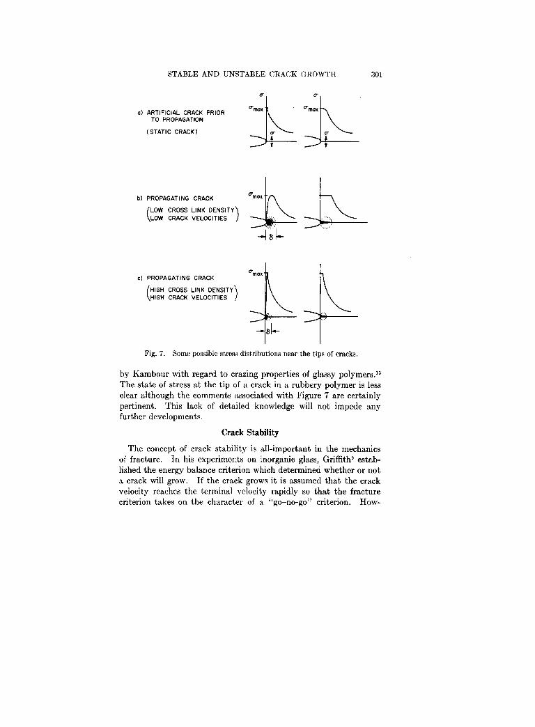
Various modifications have therefore been proposed to achieve stress solutions compatible with physics.18,26 Since the stresses for a freshly cut and stationary crack must be finite as the tip is ap- proached, one would observe the maximum tensile stress ahead of the crack to have a distribution such as in Figure 712. However, as the crack grows the material ahead of the crack disintegrates, say, by forming small voids which subsequently grow; when the crack tip reaches them, the material can no longer sustain a stress. Therefore, the stresses must drop to zero at the crack tip (cf. Figs. 7b and 7~). It may well be that this limited domain of stress decline is on the order of the surface roughness exhibited in Figure 3. A stress distribution representation which approximates the expected one and which constitutes a reasonable improvement over that of eqs. (1) is also shown in Figures 72, and 7c where the stress across the crack axis near the tip is assumed to take on a constant value over a small region ahead of the crack. The size of this small region may depend on the speed of crack propagation.* Under the assumption of a re- gion of constant tensile stress ahead of the crack the remainder of the stress field can be analyzed,7’8*2” thus leading to a potentially more realistic stress distribution around a crack.
For glassy polymers this latter modification is probably realistic in that the constant stress at the tip of the crack can be associated with a yield stress as has been done for metals.1s~2s For instance the yielding of polypropylene produces the wedge-shaped region ahead of the crack in Figure 4, within which the stress across the crack axis is nearly constant; a similar observation has been made
STABLE AND UNSTABLE CRACK GROWTH 301
a) ARTIFICIAL CRACK PRIOR TO PROPAGATION
( STATIC CRACK)
$ j-&
b) PROPAGATING CRACK
cl PROPAGATING CRACK ombx
( HIGH CROSS LINK DENSITY HIGH CRACK VELOCITIES
G:L
.:. .-._ ..’ .,..
SL
Fig. 7. Some possible stress distributions near the tips of cracks.
by Kambour with regard to crazing properties of glassy polymers.15 The state of stress at the tip of a crack in a rubbery polymer is less clear although the comments associated with Figure 7 are certainly pertinent. This lack of detailed knowledge will not impede any further developments.
Crack Stability
The concept of crack stability is ail-important in the mechanics of fracture. In his experiments on inorganic glass, Griffithg estab- lished the energy balance criterion which determined whether or not a crack will grow. If the crack grows it is assumed that the crack velocity reaches the terminal velocity rapidly so that the fracture criterion takes on the character of a “go-no-go” criterion. How-
302 W. G. KNAUSS
ever, it has been observed in both inorganic glasses and in metals that slow crack propagation can occur at loads below those predicted by the Griffith criterion and catastrophic failure does not occur until the crack has grown to a sufficient size to satisfy the postulated energy-stability criterion. The same observation holds also for polymers, except that the phenomenon of delayed instability is more pronounced. Figure 8 demonstrates the growth histories of cracks of equal initial size in sheet material of a carboxyl terminated hydrocarbon rubber (polybutadiene acrylic acid) under varying degrees of strain. The striking features are that (I) the crack propa- gates slowly first and then accelerates in a short time span, and (2) relatively small changes in strain cause significant changes in the transition time of slow-to-fast crack propagation. Our immedi- ate aim will be to illustrate this behavior analytically making use of the results of continuum stress analysis.
Fig. 8. Crack velocity histories under varying strains (stresses) in polybutadine acylic acid, sheet, thickness 4 in.
STABLE AND UNSTABLE CRACK GROWTH 303
t [set]
Fig. 9. Crack velocity in strip geometry (Fig. 6) under step strain (strain achieved in leas than 0.015 set). Solithane 113, 50/50.
Although one does not know the precise stress distribution at the tip of the crack in a realistic situation, one is certain that the stress and strain distribution at the base of the crack in the geometries of Figures 5 and 6 are at least very nearly the same, while the magnitude of the stresses may differ. Therefore, if we know the growth be- havior of the crack in one geometry it may be possible to determine the growth behavior in the other geometry.
To that end we measure experimentally the crack velocity in the strip geometry 6 under a rapidly applied strain. In tests, the results of which are shown in Figure 9, the strains were achieved within less than 15 msec and the crack velocity was found virtually constant with time. Repetitions of such tests for many strain values and at different temperatures resulted in the data of Figure 10 which could be superposed very nicely into a master curve by the standard time-temperature shift procedure.*‘*
Figure 11 shows such master curves of polyurethane rubber sheets of different thickness. Clearly there is a difference in the strain- velocity relation for sheets of different thickness which is associated
* The shift factor derived from this data agrees very well with that obt,ained from relaxation and other failure data.
:304 W. G. KNAUSS
Fig. IO. Crack velocit,y in strip geomet,ry as a function of gross &rain and temperatwe. Solithane 113, 50/50; sheet thickness 0.1 in.
with changes in the three-dimensional stress field at the tip of the crack.28 While this phenomenon is hardly recognized or even dis- putedla in connection with polymer fracture it is nevertheless real and important but of no immediate consequence for our further dis- cussion. We shall now attempt to employ the experimental data of stable crack growth (Fig. 11) to predict unstable crack growth in the geometry of Figure S.
The strain across the crack axis ahead of the crack tip for the strip geometry is, using eqs. (1) and (3)
CEy)tip = co JgT!$) ,le (strip geometry) (4)
while for the geometry of Figure 5 it is, using eqs. (1) and (2)
l-VPdC Ccv)tip = ~~ __ E 2/j;
(infinite sheet geometry) (5)
provided the material is elastic. For a viscoelastic material this strain would depend on the time history of the load as well as that
STABLE ANT) UNSTABLE CRACK (:ROWTH 305
Fig. 11. Master strain-velocity relation for three sheet thickness, Solithane 113, 50/50.
of the crack length c by way of the viscoelastic properties. For a rubbery material this time dependence is minimal provided the crack velocity is small. This restriction is not grossly violated as long as the crack grows slowly, i.e., prior to the period of velocity transition. After the crack propagates fast a more careful analysis is required. For our purposes of demonstrating crack instability, eq. (5) is suffi- cient.
We calculate now the crack instability behavior under the assump- tion that the crack velocity C depends only on the current strain at the crack tip, i.e., when
then (6)
&rip = isheet
Since we have an experimental relation for the velocity Estrip as a function of the applied strain co in Figures 10 and 11,
(7)
306 W. G. KNAUSS
we derive from the postulated equalities (6), using eqs. (4) and (5) that
Figures 10 and 11 suggest that f(&ri,) is approximated reasonably well by a simple power law
.f(Cstrip) = ~(ktrip)’ (9)
neglecting the fact that crack propagation may not be possible below a certain strain; modifications to that effect can be easily introduced. Substitution of eq. (9) into eq. (8) gives
dc/dt = { (1 - iJ2)/&rb) 1’2~[P/E]%(t)“2~ (10)
which equation can be integrated to yield
I”[1 - p] = 1 (11)
where E = c(t)/c(O),
T = ((1 - 12)/OL2Sb)1’28[P/E]“BC(O)P1
P = (1 - %3/w
Because no upper limit has been placed on the crack velocity through inertial considerations, the velocity may become unbounded and lead to infinite crack length c in the finite time
t+ = (E/P)“~/pR~(0)p R = ( (1 - ~~)/cr%rb 1 l/Z0
Indeed the velocity is, as a function of time, given by
(12)
d.ydT = (1 - pT)-o+p)‘P (13)
which is unbounded at 7 = l/p, t = t* ; of course eq. (13) is not valid when the velocity is too large because of the assumed lack of material inertia and because of the incomplete viscoelastic stress analysis. Figure 12 shows a plot of eq. (11) for a value of p = l/6 which value was taken from Figure 10. There is clearly a sharp velocity transi- tion just prior to t = t* which is thus a measure of the time at which the crack becomes unstable. This instability time depends on the applied gross strain P/E with the inverse 6th power, according to eq. (la), and on the initial crack length co with the inverse second
STABLE AND UNSTABLE CRACK GROWTH 307
Fig. 12. Slow-fast velocity transition according to eq. (11). p = 2, 6 = %.
power. While these numerical interpretations are open to discussion in view of the somewhat liberal assumptions made in this develop- ment, the trends exhibited by these results are certainly in the right direction.
Particular attention is called to the effect of initial crack size on the time of instability. If many specimens, containing flaws of statistically varying size are tested, one should expect significant data scatter, small defects leading to long failure times and conversely. Furthermore, the data scatter of failure times is the higher the lower the strain, as is indeed observed in experiments [cf. eq. (la)].
Having demonstrated how the minimal knowledge of the stress field at the tip of a crack can predict crack instability behavior of a single crack, from crack propagation data obtained under stable conditions, we turn now to the problem of the more stable growth of many cracks in a sheet under constant strain. Under this condition one may exepect the development of a large number of cracks (cf. Fig. 13) the growth rate of which decreases continuously.
Berry has shown 2g that the stress P in a sheet of area A, contain- ing a crack of length 2c and strained by an amount E, the boundaries being thereafter fixed, is,
I’ = Ec/[l + (d/A)] (14)
308 W. G. KNAUSS
If there are more than one crack each of length cl this relation is readily modified to
which relation holds for cracks small compared to the sheet dimen- sions and for cracks separated by distances more than two or three times the respective crack lengths. If the cracks are situated closer to each other, then the stress could be even smaller; eq. (15) will then be an upper bound on the stresses in a sheet under constant strain and thus crack propagation velocities calculated on the basis of eq. (15) could be larger than those based on a more accurate repre- sentation. If we now use the crack speed-load relation (10) for the growth history of the crack, along with eq. (15) we obtain
i = 1,2,3, , . . . N
This set of ordinary first-order, nonlinear differential equations must satisfy the initial conditions cl(O) = cl0 where the initial crack lengths (defect sizes) follow some statistical distribution. Noting* that the
denominator Q(t) = 1 + (r/A) $I c?(t) is independent of the index
i we find that the differential equations 16 become the same for all values of i, i.e.,
or
x4 us d[/dr =
1 + (N~to~/‘A)5~ F(O) = 1 (17)
where Eo is the rms initial crack length. In general eq. (17) must be solved numerically. However, if l/P is an integer, the denomi-
* The writer is indebted to Professor H. Keller for discussions on these equa- tions.
STABLE AND UNSTABLE CRACK GROWTH 309
0) /------0.25mm -----d b)
Fig. 13. Sheet containing many cracks (dental dam rubber 0.01 in. thick):(a) 3 days; (b) 8 days after application of 60% strain.
nator on the right-hand side can be expanded by the binomialtheorem to yield
Using again a value of 1/#3 = 6 one finds
T = a(1 - t-“) + 6[Na@/A] In t
This implicit relation for the (nondimensional) crack size t is plottedin Figure 14 for different values of N&?/A. Note that for N small,only the first term in eq. (19) is significant which represents the un-stable crack history expressed by eq. (11). In this case a large crack(f large), comparable in size to the sheet dimensions may result in atime t - t*. On the other hand, if N is large although & may be very
310 W. C:. KNAUSR
6(
Fig. 14. Crack size histories for cracks in a sheet tmder constant strain. & = initial rme crack size, N = total nllmber of cracks, A = sheet area.
small, then a long time may be required before the cracks have grown to sizes comparable with the sheet dimensions. Furthermore, if, as Rege130 suggests, the number of cracks increases with time then the rate of crack growth should decrease even stronger than indicated in Figure 14.
We are thus faced with the seemingly paradoxical conclusion that if one is interested in preserving some strength of a material under constant strain over a long period of time one should choose a ma- terial with as many small initial defects as possible, rather than a near-perfect material with few imperfections.
From a practical viewpoint it is interesting to note that the latter result appears to be in agreement with experience in the solid pro- pellant rocket industry. In this branch of polymer industry it has been observed that the life of a rocket motor, subjected to loads which produce hoop tension along the internal bore surface, may be
STABLE AND UNSTABLE CRACK GROWTH 311
extended if the surface is made polymer-poor rather than polymer- rich as might result in casting against a smooth surface. A polymer- poor surface contains a large number of initial defects in the form of the solid particles (filler) around which voids can form. To take advantage of all possible voids for stress relief in the surface layer, one has even resorted to treatment of the material near the surface with solvent which separates the polymer matrix from the particles and produces the maximum number of voids.
Heretofore, the mechanics of these beneficial producers were hardly understood. We offer the above calculations as an initial explanation for these empirical results.
Similar considerations may be in order with respect to craze- forming plastics.
In closing this discussion on unstable crack growth we point out in connection with Figure 14 that in constant strain test the sample- to-sample variation of defect density (N/A) and crack sizes cl0 may cause inordinate changes in failure times, especially at low values of applied strain, since then the characteristic time t* is very large.
Conclusion
In the previous pages we have attempted to outline the basic difficulties which confront the continuum mechanician concerned with fracture processes in viscoelastic materials. The problems may range from inability of defining the shape and size of defects to inability of solving the pertinent boundary value problem even if the geometry and the material behavior were completely determined.
In spite of such basic difficulties continuum mechanics provides useful tools to predict crack propagation behavior in viscoelastic materials. While the foregoing examples should be considered as being largely of a qualitative nature these calculations can be sub- jected to obvious refinements. An example of how the presently available tools of continuum mechanics can lead to excellent predic- tions of the crack propagation data in Figure 10 has been demon- strated recently in our laboratory.31
Most of the work contained herein has been sponsored by the National Aero- nautics and Space Administration, Research Grant No. NsG-172-60, GALCIT 120, to the California Institute of Technology.
3 12 W. G. KNAUSS
References
1. See, e.g., C. J. Phillips, Amer. Scientist, 53, No. 1, 20 (1965). 2. A. JI. Bueche, “The -Mechanisms of Polymer Failure,” in Conference on
Fract~cre Proceedings of Swampscott Conference on Fracture, Swampscott, Mass., 1959, National Academy of Science, National Research Council.
3. W. G. Knauss, Intern. J. Fracture Me&., 3, No. 4, 267 (1967). 4. M. L. Williams, ‘(The Fracture of Viscoelastic Material,” in Fracrure of
Solids, D. C. Drucker and J. J. Gilman, Eds., Interscience, New York, 1963. 5. J. R. Rice, Intern. J. Fraclure Mech., 2, No. 2, 426 (1966). 6. B. A. Bilby, A. H. Cottrell, and K. H. Swinden, The Speed of Plastic Yield
From a Notch. Proc. Roy. Sot. (London), Ser. A, 272, 304 (1963). 7. 2. Olesiak and M. P. Wnuk, Intern. J. Fracture Mech., (in press). 8. M. P. Wnnk and W. G:. Knauss, Delayed Fracture in Viscoelastic-Plastic
Solids, California Ir&itute of Technology, GALCIT SM 68-8, March 1968. 9. A. A. Griffith, The Phenomena of Rupture and Flow in Solids. Phil. Trans.
Roy. Sot. (London), Ser. A, 221, 163 (1920). 10. E. Orowan, “Fundamentals of Brittle Behavior in Metals,” in Fatigue and
Fracture of Metals, W. M. Murray, Ed., Wiley, New York, 1952, pp. 139-167. 11. G. II. Irwin, “Fracture Dynamics, ” in Fractzlring of Metals, American
Society for Metals, Cleveland, 1948, pp. 147-166. 12. M. L. Williams, “Initiation and Growt,h of Viscoelastic Fracture,” Intern.
J. Fract. Mech., 1. No. 4, 292 (1965). 13. R. S. Rivlin and A. G. Thomas, J. Polym. Sci., 10, 192 (1952). 14. W. G. Knauss, “The Time-Dependent Fracture of Viscoelastic Materials,”
Proceedings of t,he First International Congress on Fracture, Sendai, Japan, Sept. 1965.
15. 11. P. Kambour, The Role of Crazing in the Mechanism of Fracture of Glassy Polymers, General Electric Company, Report No. 67-C-085, March 1967.
16. L. C. Cessna and S. S. Sternstein, “Viscoelasticity and Plasticity Con- siderations in the Fract,ure of Glasslike High Polymers,” in Fundamental Phe- nomena in the Materials Sciences. Vol. 4, Plenum Press, New York, 1967, pp. 45-79.
17. J. B. Walsh and A. C. Mackenzie, J. Mech. Phys. Solids, 7, 247 (1959). 18. D. S. Dugdale, J. Me& Phys. Solids, 8, 100 (1960). 19. F. Bueche and J. C. Halpin, J. Appl. Phys., 35, No. 1, 36 (1964). 20. P. J. Blatz, “Finite Elastic Deformation of a Plane Strain, Wedge-Shaped
Radical Crack in a Compressible Cylinder, ” in Second Order Effect in Elasticity, Plasticity and Fluid Dynamics, M. Reiner and D. Abir, Eds., Pergamon Press, New York, 1964.
21. W. G. Knanss, Stresses Near a Crack in a Rubber Sheet, Erpll. Mech., 8, No. 4, 177 (1968).
22. W. G. Knauss, unpublished, Work on Finite Element, Large Deformation Calculations in Elliptically Perforated Rubber Sheets.
23. C. E. Inglis, Stresses in a Plate Due to the Presence of Cracks and Sharp Corners. Tmns. Inst., Naval Architects (London), 60, 219 (1913).
24. 11. L. Williams, J. ilppl. Mech., 24, 109 (1957).
STABLE AND UNSTABLE CRACK GROWTH 313
25. G. I. Barenblatt, “The Mst~hematical Theory of Equilibrium Cracks in Brittle Fracture,” in Advances in Applied Mechanics, Academic Press, New York, 1962, Vol. VII, pp. 55-129.
26. J. N. Goodier and F. A. Field, “Plastic Energy Dissipation in Crack Propagation,” in Fracture of Solids, Interscience, New York, 1962, p. 103.
27. M. L. Williams, R. F. Landel, and J. D. Ferry, J. Amer. Chem. SOL, 77, 3701 (1955).
28. G. It. Irwin, J. Basic Eng., Trans. ASME, Ser. D, 82, No. 2, 417 (1960). 29. J. P. Berry, J. Mech. Phys. Solids, 8, 194 (1960). 30. V. R. Regel, On the Kinetics of the Growth of Cracks During the Breaking
of Solids, Sov. Phys., Tech. Phys., 1, No. 2, 353 (1956). 31. H. K. Mueller, Stable Crack Propagation in a Viscoelastic Strip, California
Institute of Technology, Pasadena, California, Ph.D. Thesis, June 1968. Also NASA Contractor Report NASA CR-1279.