Series Variations Series Seal material CG5-S CJ5-S NBR FKM This product cannot be used in the food zone. Refer to the Product Specific Precautions (page 1079) for details. CJ5-S Series Stainless Steel Cylinder ø10, ø16 CG5-S Series ø20, ø25, ø32, ø40, ø50, ø63, ø80, ø100 Applicable for use in an environment with water splashing such as food processing, etc. For use with grease for food processing machines (Approved by NSF-H1) All stainless steel specifications (External parts) Stainless steel 304 is used for external metal parts. Corrosion resistance is improved even in environments with exposure to water. Relation of Liquid Entry and Sliding Distance 15 10 5 0 50 100 150 200 x 250 300 Amount of liquid entry (g) Standard cylinder Stainless steel cylinder Sliding distance (km) Special scraper Two types of seal material NBR or FKM can be selected to accommodate the application. (Nitrile rubber) (Fluororubber) Exterior configuration reduces residual liquid • Electropolishing of mounting bracket surfaces makes them smoother to prevent build-up of liquids and foreign matter. • Plugs are provided for unused mounting threads (CG5-S series) to prevent residue build-up in the threads. Plug 10 16 20 25 32 Bore size (mm) 40 50 63 80 100 Applicable auto switch Water resistant D-H7BAL Water resistant D-G5BAL Special scraper (Standard) Prevents water from entering the cylinder. Conditions Working fluid ······· Air Pressure ············· 0.5 MPa Liquid ·················· Water-soluble coolant Piston speed ······· 200 mm/s Operating frequency··· 60 cpm Can be disassembled (CG5-S series ø20 to 40) Since seals are replaceable, this extends the life of the cylinder. (Before disassembly, be sure to refer to the section regarding maintenance under “Specific Product Precautions” on page 1080.) 1063 HYWater Resistant D--XTechnical Data CJ5 CG5
Transcript
Series Variations
Series Seal material
CG5-S
CJ5-SNBR
FKM
This product cannot be used in the food zone. Refer to the Product Specific Precautions (page 1079) for details.
Applicable for use in an environmentwith water splashing such as food processing, etc.
For use with grease for food processing machines (Approved by NSF-H1)
All stainless steel specifications (External parts)Stainless steel 304 is used for external metal parts.Corrosion resistance is improved even in environments with exposure to water.
Relation of Liquid Entry and Sliding Distance
15
10
5
0 50 100 150 200
x
250 300
Am
ount
of l
iqui
d en
try
(g)
Standard cylinder
Stainless steel cylinder
Sliding distance (km)
Special scraper
Two types of seal material
NBR or FKM can be selected to accommodate the application.
(Nitrile rubber) (Fluororubber)
Exterior configuration reduces residual liquid• Electropolishing of mounting
bracket surfaces makes them smoother to prevent build-up of liquids and foreign matter.
• Plugs are provided for unused mounting threads (CG5-S series) to prevent residue build-up in the threads.
Plug
10 16 20 25 32
Bore size (mm)
40 50 63 80 100Applicableauto switch
Water resistantD-H7BAL
Water resistantD-G5BAL
Special scraper (Standard)Prevents water from entering the cylinder.
Can be disassembled(CG5-S series ø20 to 40)Since seals are replaceable, this extends the life of the cylinder.(Before disassembly, be sure to refer to the section regarding maintenance under “Specific Product Precautions” on page 1080.)
1063
CJ5CG5
HYWater Resistant
D-
-XTechnicalData
CJ5CG5
With auto switch
With auto switch
BLFD Cylinder stroke (mm)
Refer to “Standard Stroke” on page 1065.
Stainless steel cylinder
CDJ5 L 16 S R 60
RV
1016
10 mm16 mm
CJ5 L 16 S R 60
Special functionType Electricalentry DC 3
(L)5
(Z)0.5(Nil)
1(M)
5 V, 12 V
12 V
24 V
Description
Foot
Flange
T-bracket ∗
16CJK-L016 Stainless steel
CJK-F016 Stainless steel
CJ-T016 Stainless steel
Foot x 1
Flange x 1
T-bracket x 1
10CJ-L016 Stainless steel
CJ-F016 Stainless steel
CJ-T010 Stainless steel
Built-in Magnet Cylinder Model
Bore size
Mounting typeBasic type
Axial foot typeRod side flange typeDouble clevis type
∗ Only perpendicular to the axis for double clevis type.
Indicatorlight
Wiring(Output)
Load voltage Auto switch modelBand mounting(ø10, ø16)
Perpendicular In-line
Lead wire length (m)∗Pre-wired connector
Applicableload
Grommet Relay,PLC
IC circuit
• For details about auto switches with pre-wired connector, refer to pages 1648 and 1649.
∗ Solid state auto switches marked with “ ” are produced upon receipt of order.
Mounting Bracket Part No.Bore size (mm)
Mounting bracket
∗ T-bracket is applicable to the double clevis type (D).
Grease pack for stainless steel cylinders/Part no.: GR-R-010 (10 g)
3-wire(NPN)
3-wire(PNP)
2-wire
YesWater resistant
(2-color indicator)
Solidstateauto
switch
How to Order
CJ5-S Seriesø10, ø16
Stainless Steel Cylinder
M9BA
M9NAVM9PAVM9BAV
M9NAM9PAM9BA
NilSn
2 pcs. 1 pc.
“n” pcs.
Number of auto switches
Applicable Auto Switches/Refer to pages 1575 to 1701 for further information on auto switches.
∗ Lead wire length symbols: Nil··········0.5 m (Example) D-M9NA M ··········1 m (Example) D-M9NAM L ··········3 m (Example) D-M9NAL Z ··········5 m (Example) D-M9NAZ
If a built-in magnet cylinder without an auto switch is required, suffix the symbol “-B” (Band mounting type) to the end of part number.(Example) CDJ5B10SV-45R-B
∗ Foot/Flange brackets are shipped together with the product, but not assembled.
∗ For the applicable auto switch model, refer to the table below.
∗ Only band mounting is applicable to auto switch cylinders.
∗ If a built-in magnet cylinder without an auto switch is required, refer to the model of built-in magnet cylinder.
1064
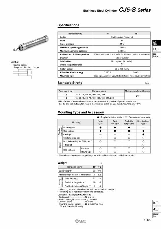
Action
Fluid
Proof pressure
Maximum operating pressure
Minimum operating pressure
Ambient and fluid temperature
Cushion
Lubrication
Stroke length tolerance
Double acting, Single rod
Air
1 MPa
0.7 MPa
0.1 MPa
Without auto switch: –10 to 70°C With auto switch: –10 to 60°C
Rubber bumper
Not required (Non-lube)
Mounting
Bore size (mm)
10
16
15, 30, 45, 60, 75, 100, 125, 150
15, 30, 45, 60, 75, 100, 125, 150, 175, 200
Standard stroke
400
Maximum manufacturable stroke
Piston speed
Allowable kinetic energy
Mounting type
50 to 750 mm/s
Basic type, Axial foot type, Rod side flange type, Double clevis type
0.035 J 0.090 J
(mm)
(g)
10
52
4
22
16
6
16
96
6.5
22
16
16
Bore size (mm)
Weight
Specifications
Standard Stroke
Mounting Type and Accessory
Bore size (mm) 10 16
SymbolDouble acting, Single rod, Rubber bumper
+ 1.0 0
∗ Manufacture of intermediate strokes at 1 mm intervals is possible. (Spacers are not used.) ∗ For the one with auto switch, refer to the minimum stroke for auto switch mounting. (P. 1077)
Basictype
Axialfoot type
Rod sideflange type
Double clevistype ∗
Sta
ndar
deq
uipm
ent
Opt
ion
Mounting nut
Rod end nut
Clevis pin
Single knuckle joint
Double knuckle joint (With pin) ∗
T-bracket
Flat type
Round typeRod end cap
∗ Pin and retaining ring are shipped together with double clevis and double knuckle joint.
Mou
nting
brac
ket w
eight Axial foot type
Rod side flange type
Double clevis type (With pin) ∗∗
Basic weight ∗
Additional weight per each 15 mm of stroke
∗ Mounting nut and rod end nut are included in the basic weight.∗∗ Mounting nut is not included in double clevis type.
• For details about auto switches with pre-wired connector, refer to pages 1648 and 1649.
∗ Solid state auto switches marked with “ ” are produced upon receipt of order.
Mountingbracket
Min.order
CG-L020SUS
CG-F020SUS
CG-L025SUS
CG-F025SUS
CG-L032SUS
CG-F032SUS
CG-L040SUS
CG-F040SUS
CG-L050SUS
CG-F050SUS
CG-L063SUS
CG-F063SUS
CG-L080SUS
CG-F080SUS
CG-L100SUS
CG-F100SUS
Note) When ordering the foot bracket, order 2 pcs. per cylinder.
Grease pack for stainless steel cylinders/Part no.: GR-R-010 (10 g)
Built-in Magnet Cylinder ModelIf a built-in magnet cylinder without an auto switch is required, there is no need to enter the symbol for the auto switch.(Example) CDG5BA40SV-100
Without auto switch: –10 to 70°C With auto switch: –10 to 60°C
Rubber bumper, Air cushion
Not required (Non-lube)
Up to 1000 mm,
Up to 1500 mm
20 25 32 40 50 63 80 100
(kg)
Bore size (mm) 100
8.13
9.50
9.29
9.94
1.65
0.78
1.07
0.73
0.16
80
5.20
5.91
5.86
6.48
1.65
0.53
0.73
0.50
0.14
63
2.73
3.19
3.25
3.26
0.46
0.22
0.33
0.33
0.07
50
1.78
2.12
2.04
2.17
0.46
0.22
0.33
0.27
0.06
40
0.97
1.13
1.12
1.12
0.18
0.11
0.18
0.18
0.02
32
0.61
0.72
0.71
0.72
0.18
0.07
0.09
0.14
0.03
25
0.42
0.53
0.53
0.48
0.08
0.07
0.09
0.08
0.02
20
0.32
0.40
0.43
0.37
0.08
0.04
0.05
0.06
0.02
Mounting
Accessory/For details, refer to page 1076.
Weight
Change of rod end shape
Heat resistant cylinder (150°C)∗
Symbol Specifications
Bore size (mm)
20
25
32
40
50, 63
80
100
25, 50, 75, 100, 125, 150, 200
25, 50, 75, 100, 125, 150, 200250, 300
201 to 350
301 to 400
301 to 450
301 to 800
301 to 1200
301 to 1400
301 to 1500
Standard stroke Long stroke
1500
Maximum manufacturable stroke
Standard Stroke
50 to 1000 mm/s 50 to 700 mm/s
Bore size (mm)
∗ Heat resistant grease (non-food grease) is used.
SymbolDouble acting, Single rod, Rubber bumper
Air cushion
Made to Order Specifications(For details, refer to pages 1703 to 1896.)
-XA-XB6
Action
Fluid
Proof pressure
Maximum operating pressure
Minimum operating pressure
Ambient and fluid temperature
Cushion
Lubrication
Piston speed
Stroke length tolerance
Mounting type
Up to 1000 mm, Up to 1200 mmst + 1.4 0
st + 1.4 0st + 1.8
0 st + 1.8 0
Basic type, Axial foot type, Rod side flange type, Head side flange type, Clevis integrated type
∗ Manufacture of intermediate strokes at 1 mm intervals is possible. (Spacers are not used.) ∗ Long stroke applies to the axial foot type and the rod side flange type. If other mounting brackets are used, or the length exceeds the long stroke limit, the stroke should be determined based on the stroke selection table (front matter pages, CG1).
Rod end nut
Single knuckle joint
Double knuckle joint (With pin & retaining ring)
Pivot bracket (With pin and retaining ring)
Standardequipment
Option
Basictype
Axialfoot type
Head sideflange type
Rod sideflange type
Clevisintegrated
type
Basic type
Axial foot type
Flange type
Clevis integrated type
Pivot bracket
Single knuckle joint
Double knuckle joint (with pin)
Additional weight per each 50 mm of stroke
Additional weight with air cushion
Bas
ic w
eigh
t
(Foot type ø20, 100 stroke) Calculation: (Example) CG5LA 20SR-100 • Basic weight································ 0.40 kg (Foot type ø20)
• Additional stroke weight ············· 0.06 kg/50 ST• Air cylinder stroke ······················ 100 ST• Additional air cushion weight ····· 0.02 kg 0.40 + 0.06 x 100/50 + 0.02 = 0.54 kg
Stainless Steel Cylinder CG5-S Series
···Supplied with the product. ···Please order separately.
1071
CJ5CG5
HYWater Resistant
D-
-XTechnicalData
CJ5CG5
Construction
With rubber bumper
With air cushion
Contents
20253240
Replacement Parts/Seal Kit
CG5NSR
CG5N20SR-PS
CG5N25SR-PS
CG5N32SR-PS
CG5N40SR-PS
CG5NSV
CG5N20SV-PS
CG5N25SV-PS
CG5N32SV-PS
CG5N40SV-PS
Rubber bumper Air cushion
Set of o and !0 above
CG5ASR
CG5A20SR-PS
CG5A25SR-PS
CG5A32SR-PS
CG5A40SR-PS
CG5ASV
CG5A20SV-PS
CG5A25SV-PS
CG5A32SV-PS
CG5A40SV-PS
Set of o, !0, !1 and !2 above
No.
1234567
14151617181920
Rod cover
Head cover
Cylinder tube
Piston rod
Bumper
Rod end nut
Cushion seal
Cushion valve
Valve retainer
Lock nut
Bushing
Piston
Wearing
Cushion ring
Description Material
Component Parts
Stainless steel 304
Stainless steel 304
Stainless steel 304
Urethane
Stainless steel 304
Urethane
Stainless steel 304
Stainless steel 304
Stainless steel 304
Bearing alloy
Aluminum alloy
Resin
Aluminum alloy
Stainless steel 304 Hard chrome plated
No.
89101112212213
Water resistant scraper
Rod seal
Piston seal
Valve seal
Valve retainer gasket
Piston gasket
Cushion ring gasket
Label protector
DescriptionMaterial
NBR
PET
FKM
CautionWhen disassembling cylinders with bore sizes of ø20 through ø40, grip the double flat part of either the tube cover or the rod cover with a vise and loosen the other side with a wrench or a monkey wrench, etc., and then remove the cover. When retightening, tighten approximately 2 degrees more than the original position. (Cylinders with ø50 or larger bore sizes are tightened with a large tightening torque and cannot be disassembled.)
ø80, ø100 ø80, ø100
CG5SR CG5SV
Note 1) Component part material and surface treatment other than listed above are the same as the standard type of the CG1 series.
Note 2) For cylinders with an auto switch, the piston is fixed with a magnet.
Bore size (mm)
∗ Seal kit includes a grease pack (10 g). Order with the following part number when only the grease pack is needed. Grease pack part number: GR-R-010 (10 g)
CG5-S Series
1072
Dimensions
ALA
H
H1
(F1)
(øE
1)
2 x P(Rc, NPT, G)
K
CNA
KA
8 x J
GA GB
MM BZB2
M BM
ALA
H
2 x P(Rc, NPT, G)
K
NA
KA8 x J
GA GB
MM
Max
.WH
WA WB
BZ
M BM
(F1)
B2
øI
øI
øD
H1
(øE
1)
øD
Wθº10º
C
C
Standard1818181921212829
1212121314142020
1/81/81/81/81/41/43/81/2
1818161619192526
1212101012121717
M5 x 0.8M5 x 0.81/81/81/41/43/81/2
1822223035354040
15.519.519.527 32 32 37 37
1317171927273241
20 25 32 40 50 63 80100
7 8 81013171719
9 9.5 9.512 15.519 19 24
16.518.520 26 32 38 50 60
810121620202530
1517192328283338
33333333
3540405058587171
5 6 6 811111316
31 33 38 47 58 72 89110
5 5.5 5.5 6 7 7 10 10
6 8101418182226
3 3.53.54 5.57 7 8
29 29 35.5 44 55 69 80 100
83 83 85 93109109130131
118123125143167167201202
M8 x 1.25M10 x 1.25M10 x 1.25M14 x 1.5M18 x 1.5M18 x 1.5M22 x 1.5M26 x 1.5
M4 x 0.7M5 x 0.8M5 x 0.8M6 x 1.0M8 x 1.25M10 x 1.5M10 x 1.5M12 x 1.75
GA GB P GA GB PA AL B1 B2 BM BZ C D E1 F1 H H1 I J K KA M MM NA S ZZ
G portRc, NPT port
1818181921212829
1212121314142020
M5 x 0.8M5 x 0.81/81/81/41/43/81/2
1818161619192526
1212101012121717
M5 x 0.8M5 x 0.81/81/81/41/43/81/2
1822223035354040
15.519.519.527 32 32 37 37
1317171927273241
20 25 32 40 50 63 80100
7 8 81013171719
9 9.5 9.512 15.519 19 24
16.518.520 26 32 38 50 60
810121620202530
1517192328283338
33333333
3540405058587171
5 6 6 811111316
31 33 38 47 58 72 89110
5 5.5 5.5 6 7 7 10 10
6 8101418182226
3 3.53.54 5.57 7 8
29 29 35.5 44 55 69 80 100
83838593
109109130131
M8 x 1.25M10 x 1.25M10 x 1.25M14 x 1.5M18 x 1.5M18 x 1.5M22 x 1.5M26 x 1.5
M4 x 0.7M5 x 0.8M5 x 0.8M6 x 1.0M8 x 1.25M10 x 1.5M10 x 1.5M12 x 1.75
GA GB P GA GB PA AL B1 B2 BM BZ C D E1 F1 H H1 I J K KA M MM NA S
2222222225253031
1616161618182222
23 25 28.533 40.547.560.571
20 25 32 40 50 63 80100
118123125143167167201202
WA WB WH Wθ ZZ
(mm)
(mm)
(mm)
Basic type (B): CG5BNS : With rubber bumperRV
Width across flats B1
C±0
.1
±0.1
S + StrokeZZ + Stroke
Boresize(mm)
Strokerange
M4 x 0.7 depth 7M5 x 0.8 depth 8M5 x 0.8 depth 8M6 x 1.0 depth 12M8 x 1.25 depth 16M10 x 1.5 depth 16M10 x 1.5 depth 22M12 x 1.75 depth 23
∗ Install plug bolts, which are included, in any unused mounting holes.
Basic type (B): CG5BAS : With air cushionRV
Up to 350Up to 400Up to 450Up to 800Up to 1200Up to 1200Up to 1400Up to 1500
±0.1
±0.1
Width across flats B1
S + StrokeZZ + Stroke
Plug bolt ∗ (4 pcs. included)
Strokerange
Boresize(mm)
Up to 350Up to 400Up to 450Up to 800Up to 1200Up to 1200Up to 1400Up to 1500
Standard
G portRc, NPT port
M4 x 0.7 depth 7M5 x 0.8 depth 8M5 x 0.8 depth 8M6 x 1.0 depth 12M8 x 1.25 depth 16M10 x 1.5 depth 16M10 x 1.5 depth 22M12 x 1.75 depth 23
∗ Install plug bolts, which are included, in any unused mounting holes.
Boresize(mm)
30°30°25°20°20°20°20°20°
Plug bolt ∗ (4 pcs. included)
Stainless Steel Cylinder CG5-S Series
1073
CJ5CG5
HYWater Resistant
D-
-XTechnicalData
CJ5CG5
Dimensions
ALA K
KA8 x J 4 x øLDC
GA GB
MM
LXLZ
BL
H
X Y XY
H
H1
MLT
ALA
H
KKA
GAGB
MM
B
FT
M8 x J4 x øFD CFX
2 x P(Rc, NPT, G)
2 x P(Rc, NPT, G)
øD
H1
øD
øI
øI
C
C
FXB
1818181921212829
1212121314142020
1/8 (1)
1/8 (1)
1/81/81/41/43/81/2
1818161619192526
1212101012121717
M5 x 0.8M5 x 0.8
1/81/81/41/43/81/2
1822223035354040
15.519.519.527 32 32 37 37
1317171927273241
20 25 32 40 50 63 80100
50 50 50 60 75 90100125
810121620202530
36 36 38 46 58 70 82100
5.5 5.5 6.6 6.6 9 11 11 14
3540405058587171
5 6 6 811111316
31 33 38 47 58 72 89110
M4 x 0.7M5 x 0.8M5 x 0.8M6 x 1.0M8 x 1.25M10 x 1.5M10 x 1.5M12 x 1.75
5 5.5 5.5 6 7 7 10 10
6 8101418182226
3 3.53.54 5.57 7 8
29 29 35.5 44 55 69 80 100
83 83 85 93109109130131
121 126.5128.5147 172.5174 208 210
M8 x 1.25M10 x 1.25M10 x 1.25M14 x 1.5M18 x 1.5M18 x 1.5M22 x 1.5M26 x 1.5
16.518.520 26 32 38 50 60
GA GB P GA GB PA AL B1 B C D FX FD H
6 6 6 6 9 9 910
FT H1 I J K KA M MM NA S ZZ
1818181921212829
1212121314142020
1/8 (1)
1/8 (1)
1/81/81/41/43/81/2
1818161619192526
1212101012121717
M5 x 0.8M5 x 0.8
1/81/81/41/43/81/2
1822223035354040
15.519.519.527 32 32 37 37
1317171927273241
20 25 32 40 50 63 80100
37.5 41.5 44 53.5 69 81 99.5125
810121620202530
3540405058587171
5 6 6 811111316
31 33 38 47 58 72 89110
M4 x 0.7M5 x 0.8M5 x 0.8M6 x 1.0M8 x 1.25M10 x 1.5M10 x 1.5M12 x 1.75
5 5.5 5.5 6 7 7 10 10
6 8101418182226
3 3.53.54 5.57 7 8
16.518.520 26 32 38 50 60
GA GB P GA GB PA AL B1 B C D H H1 I J K KA
6 6 7.2 7.210 12 12 14
LD
2225253040455570
LH
5959596674748283
LS
33334446
LT
40 44 44 54 66 82100120
LX
50 60 60 75 90110130160
LZ M
20 25 32 40 50 63 80100
29 29 35.5 44 55 69 80 100
83 83 85 93109109130131
124 129.5131.5150 176.5178 212 216
M8 x 1.25M10 x 1.25M10 x 1.25M14 x 1.5M18 x 1.5M18 x 1.5M22 x 1.5M26 x 1.5
MM NA S
15 15 16 16.521.521.528 30
X
7 7 6 6.511.511.517 15
Y ZZ
(mm)
(mm)
(mm)
Axial foot type (L): CG5L S RV
NA
±0.1
±0.1
Width across flats B1
LS + Stroke
ZZ + Stroke
Width across flats NA
S + Stroke
Boresize(mm)
Strokerange
Standard
G portRc, NPT port
Up to 350Up to 400Up to 450Up to 800Up to 1200Up to 1200Up to 1400Up to 1500
∗ Foot brackets and plug bolts are installed when shipped from factory.Note 1) ø20 and ø25 cylinders with an air cushion: M5 x 0.8Note 2) Refer to the basic type (B)/CG5BAS∗ for the dimensions of air cushion needles.
Boresize(mm)
Rod side flange type (F): CG5F S RV
NA
±0.1
5
±0.1
±0.1
±0.15
Width across flats B1
Width across flats NA
S + Stroke
ZZ + Stroke
Boresize(mm)
Strokerange
Standard
G portRc, NPT port
Up to 350Up to 400Up to 450Up to 800Up to 1200Up to 1200Up to 1400Up to 1500
∗ Flange bracket and plug bolt are installed when shipped from factory.Note 1) ø20 and ø25 cylinders with an air cushion: M5 x 0.8Note 2) Refer to the basic type (B)/CG5BAS∗ for the dimensions of air cushion needles.
CG5-S Series
1074
Dimensions
ALA K
NA
KA4 x J
GA GB
MM
H
L
LF
LY
LT
RRU
LVLX
CXLL
LHLE
M
LPLG
ALA
H
K
GA GB
MM
FT
M
H1
øD
2 x P(Rc, NPT, G)
øI
8 x J4 x øFD
4 x øLD
C
C
FXB
øC
I
øI
2 x P(Rc, NPT, G)
H1
øD
C
C
FX
B
1818181921212829
1212121314142020
1/8 (1)
1/8 (1)
1/81/81/41/43/81/2
1818161619192526
1212101012121717
M5 x 0.8M5 x 0.8
1/81/81/41/43/81/2
1822223035354040
15.519.519.527 32 32 37 37
1317171927273241
20 25 32 40 50 63 80100
50 50 50 60 75 90100125
810121620202530
36 36 38 46 58 70 82100
5.5 5.5 6.6 6.6 9 11 11 14
3540405058587171
5 6 6 811111316
31 33 38 47 58 72 89110
M4 x 0.7M5 x 0.8M5 x 0.8M6 x 1.0M8 x 1.25M10 x 1.5M10 x 1.5M12 x 1.75
5 5.5 5.5 6 7 7 10 10
6 8101418182226
3 3.53.54 5.57 7 8
29 29 35.5 44 55 69 80 100
83 83 85 93109109130131
124129131149176176210212
M8 x 1.25M10 x 1.25M10 x 1.25M14 x 1.5M18 x 1.5M18 x 1.5M22 x 1.5M26 x 1.5
16.518.520 26 32 38 50 60
GA GB P GA GB PA AL B1 B C D FX FD H
6 6 6 6 9 9 910
FT H1 I J K KA M MM NA S ZZ
1818181921212829
1212121314142020
1/8 (1)
1/8 (1)
1/81/81/41/43/81/2
1818161619192526
1212101012121717
M5 x 0.8M5 x 0.8
1/81/81/41/43/81/2
1822223035354040
15.519.519.527 32 32 37 37
1317171927273241
20 25 32 40 50 63 80100
810121620202530
3540405058587171
5 6 6 811111316
31 33 38 47 58 72 89110
M4 x 0.7M5 x 0.8M5 x 0.8M6 x 1.0M8 x 1.25M10 x 1.5M10 x 1.5M12 x 1.75
5 5.5 5.5 6 7 7 10 10
6 8101418182226
3 3.53.54 5.57 7 8
29 29 35.5 44 55 69 80 100
M8 x 1.25M10 x 1.25M10 x 1.25M14 x 1.5M18 x 1.5M18 x 1.5M22 x 1.5M26 x 1.5
Up to 200Up to 300Up to 300Up to 500Up to 600Up to 600Up to 750Up to 750
∗ Foot brackets and plug bolts are installed when shipped from factory.Note 1) ø20 and ø25 cylinders with an air cushion: M5 x 0.8Note 2) Refer to the basic type (B)/CG5BAS∗ for the dimensions of air cushion needles.
Integrated clevis type (E): CG5E SRV
NA
ZZ + Stroke
Width across flats B1
±0.1
±0.1
S + StrokeZ + Stroke
LZ + Stroke
øCD hole H10Shaft d9
Boresize(mm)
Strokerange
Standard
G portRc, NPT port
Boresize(mm)
Pivotbracket
Up to 200Up to 300Up to 300Up to 500Up to 600Up to 600Up to 750Up to 750
∗ Plug bolts are installed when shipped from factory.∗ Pivot bracket (with clevis pin and snap ring) are optional. (Not included.) Note 1) ø20 and ø25 cylinders with an
air cushion: M5 x 0.8Note 2) Refer to the basic type
(B)/CG5BAS∗ for the dimensions of air cushion needles.
∗ Knuckle joint pins and retaining rings are included.
Part no.Applicablebore size
(mm)
IY-G02SUS
IY-G03SUS
IY-G04SUS
IY-G05SUS
IY-G08SUS
IY-G10SUS
Applicableretaining ring
Type C 8 for axis
Type C 10 for axis
Type C 10 for axis
Type C 14 for axis
Type C 18 for axis
Type C 22 for axis
Part no.Applicablebore size
(mm)CG-E020SUS
CG-E032SUS
CG-E050SUS
CG-E080SUS
CD(Retaining
ring)
∗ Clevis pins and retaining rings are included.
∗ Retaining rings are included.
Part no.Applicablebore size
(mm)CD-E02SUS
CD-E03SUS
CD-E05SUS
CD-E08SUS∗ Retaining rings are included.
Applicableretaining ring
Type C 8 for axis
Type C 10 for axis
Type C 14 for axis
Type C 22 for axis
Part no.Applicable bore size
(mm)
NT-02SUS
NT-03SUS
NT-G04SUS
NT-05SUS
NT-08SUS
NT-10SUS
30°
L1
L1
Single Knuckle Joint Double Knuckle Joint
Knuckle Joint Pin Pivot Bracket
Clevis PinRod End Nut
CG5-S Series
Accessory Dimensions
1076
Proper Auto Switch Mounting Position (Detection at stroke end) and Mounting Height
A31.5
31.5
32.5
37
45.5
45.5
56
57
20253240506380
100
10 15 75
Minimum Stroke for Auto Switch Mounting
B24
24
25
28
36
36
46
46
D-G5BAHs
26
28.5
33
36.5
42
48.5
57.5
68
33
12
24.5
BA
A0
0.5
1016
Mounting bracket
Number of autoswitches
Basic type, Foot type, Flange type, Clevis type
10 15 60
Minimum Stroke for Auto Switch Mounting
B0
0.5
D-H7BAHs
17
20.5
16 SMC
SMC
29A B
(mm)
Operating Range (mm)
(mm)
D-G5BA205
255
325.5
406
507
637.5
807.5
1008
Operating Range (mm)
D-H7BA105
165
NBA-088S
NBA-106S
BGS1-032S
BAF-04S
BAF-05S
BAF-06S
BAF-08S
BAF-10S
Auto switchmodel
Bore size (mm)
D-G5BA
20 25 32 40 50 63 80 100
CJ5-S Series D-M9A(V) D-H7BA
≅ HS
1(Rod cover side)
2(Different sides)
2(Same side)
Minimum stroke (mm)
Switch mountingside
Switch type
Port side Port side Port side
Auto switch modelBore size (mm)
∗ Since this is a guideline including hysteresis, not meant to be guaranteed. (Assuming approximately ±30% dispersion) There may be the case to change substantially depending on an ambient environ-ment.
Proper Auto Switch Mounting Positionand Its Mounting Height
Applicable bore size (mm)
Auto switchmodel
Note) Adjust the auto switch after confirming the operating condition in the actual setting.
CG5-S Series D-G5BA
≅ HS Auto switch
Mounting bracket Basic type, Foot type, Flange type, Clevis type
1(Rod cover side)
2(Different sides)
2(Same side)
Port side Port side Port side
Number of autoswitches
Switch mountingside
Minimum stroke (mm)
Switch type
Auto Switch Mounting Bracket / Part No.
∗ With stainless steel mounting screws.
Auto switchmodel
Bore size (mm)
∗ Since this is a guideline including hysteresis, not meant to be guaranteed. (Assuming approximately ±30% dispersion) There may be the case to change substantially depending on an ambient environment.
Proper Auto Switch Mounting Positionand Its Mounting Height
Applicablebore size (mm)
Auto switchmodel
Note) Adjust the auto switch after confirming the operating condition in the actual setting.
Auto Switch Mounting Bracket / Part No.
Auto switch model
∗ With stainless steel mounting screws.
Bore size (mm)
ø10 ø16
BJ6-010S Note 1)
BJ2-010S
BJ6-016S Note 1)
BJ2-016S
D-M9AD-M9AV
D-H7BA
Note 1) Set part number which includes the auto switch mounting band (BJ2-S) and the holder kit (BJ4-1/Switch bracket: White).
Note 2) For D-M9A(V), avoid the indicator LED for mounting the switch bracket.
CJ5-S/CG5-S Series
Auto Switch Mounting
1077
CJ5CG5
HYWater Resistant
D-
-XTechnicalData
CJ5CG5
1
2
3
4
5
6
7
8
9
10
11
12
13
14
15
16
17
18
19
20
21
22
23
Parts
Material
Chemical Resistance Table
Technical Data:
Chemical Resistance Table: No influence or almost no influence: Some influence, but operational depending on conditions: Avoid use if possible: Substantial influence, not suitable for use: Not tested
SymbolChemical(Concentration weight %, Temperature °C)
Body Seal Water resistant auto switch
Stainless steel Aluminum∗ Nitrile rubber Fluororubber Resin casing Lead wire
Stainlesssteel 304 AI
NBR(–10 to 60°C)
FKM(–40 to 150°C)
PBT(–10 to 60°C)
PVC(–10 to 60°C)
Inorganicsalt
Inorganicalkali
Organicsolvent
Others(oil, gas,etc.)
Hydrochloric acid (20%, Room temperature)
Chromic acid (25%, 70°C)
Boric acid
Sulfuric acid (30%, Room temperature)
Phosphoric acid (50%, Room temperature)
Ammonium hydroxide (28%)
Sodium hydroxide (30%, Room temperature)
Calcium hydroxide
Magnesium hydroxide
Acetylene
Formic acid (25%, Room temperature)
Citric acid
Acetic acid (10%, Room temperature)
Lactic acid (5%, 20°C)
Linseed oil
Polassium chloride
Calcium chloride
Mineral oil
Sodium hypochlorite (2%, Room temperature)
Sodium chloride
Carbon dioxide
Natural gas
Boric acid
∗ Unless noted otherwise, the solution concentration is in a saturated state.∗ Chemical resistance is a guide that applies only to the stainless steel cylinder parts, and does not guarantee the performance of air cylinders (auto switches).
Be sure to perform a verification test before operating.
∗ ) Reference data
1078
Operating EnvironmentCaution on Design
Warning Warning
Caution
Mounting
Warning
Operating Precautions
Caution
Selection
Warning
Caution
CJ5-S/CG5-S Series Stainless Steel CylinderSpecific Product Precautions 1Be sure to read this before handling the products.Refer to back page 50 for Safety Instructions and pages 3 to 12 for Actuator and Auto Switch Precautions.
1. Note the weight of the stainless steel products.Since the weight of stainless steel cylinders is approximately 1.5 to 3 times heavier than the standard products (with aluminum body), be careful when calculating weight estimates. Also, when mounting the cylinder on equipment where vibration is expected, avoid using single side brackets such as the flange type, and use double side brackets such as the foot type instead.
1. Adjust the speed control for the environment in which it will be used.Speed adjustment may be changed depending on the environment.
2. Dust may accumulate on this product’s mounting screws and brackets in some operating conditions.Measures must be applied depending on the operating conditions when mounting.
1. Generally, use nitrile rubber (NBR) seals with liquids that do not contain chlorine and sulfur, and use fluoro rubber (FKM) seals with liquids that contain chlorine and sulfur.However, depending on the type and the brand of liquid (such as cleaning solvent) that splashes on the cylinder, the operating life of seals may be reduced dramatically. In cases where special additives are used, or where liquid caused trouble with the current nitrile or fluoro rubber seals in the past, request an investigation or set up a test period for the use of the seals.
2. Even the fluoro rubber specification may not be applicable depending on the type of chemicals and the operating temperature. Therefore, be sure to verify the seal's applicability before use.
1. Do not rotate the cover.If a cover is rotated when installing a cylinder or screwing a fitting into the port, it is likely to damage the junction part with cover.
2. When using pins, apply grease, etc., in order to prevent them from degrading of shape and rusting.
1. If cleaning the rotating part, grease may leak out, which shortens product service life. Thus, cleaning must be as infrequent as possible.
2. If excess water gets into mounting holes, unwanted bacteria may reproduce. Plug them with plug bolts or external covers to avoid this.
1. For details about operating precautions, refer to page 175 for the CM2 series and page 297 for the CG1 series.
Warning
1. Fully consider the compatibility of stainless steel.The corrosion resistance of stainless steel is not effective against all media and corrosive environments. Corrosion proceeds rapidly with strong hydrochloric acid, hydrofluoric acid, and high temperature ammonium gas, etc. Therefore its compatibility to the environment must be considered carefully.
2. Do not operate cylinders with auto switches in environments where oil and chemicals are used.Please contact SMC when operating in environments with coolants, cleaning solvents, various oils or chemicals, as it may cause adverse effects (faulty insulation, malfunction due to swelling of the potting resin, and hardening of lead wires, etc) to auto switches even in a short period of time. Even with the fluoro rubber seal specification, the auto switch related parts (switch body, mounting bracket, and built-in magnet) are identical to the standard specifications. Therefore, consult with SMC regarding the cylinder’s compatibility (such as chemical resistance) with an environment (chemicals, etc.) before operating.
3. Do not immerse the cylinder in water or chemicals.When the cylinder is operated in a condition with water pressure, the fluid leaks into the cylinder in the early stages. In the worst case, the fluid may back flow inside the piping and damage the solenoid valve.
2. When cleaning solvent or chemicals splashes on a cylinder, the service life may be extremely shortened. Please contact SMC for details.
3. When cleaning cylinders with steam, do it as quickly as possible, keeping the cylinder’s temperature range in mind.
4. When cleaning cylinders with a brush, etc., do not apply excessive force to the weaker parts, such as auto switch lead wire, etc.
1. Avoid installing and using a cylinder inside a food zone. <Not installable> Food zone
<Installable>Splash zone
Non-food zone
An environment where food which will be sold as merchandize, directly touches the cylinder’s components.
An environment where food which will not be sold as merchandize, directly touches the cylinder’s components.An environment where there is no contact with food.
Non-food zoneInstallable
Splash zoneInstallable
Food zoneNot installable
Food
Container
1079
CJ5CG5
HYWater Resistant
D-
-XTechnicalData
CJ5CG5
Maintenance
Warning
Precautions for the CG5-S series1. Sealant∗ is used on the threads of the connecting
sections of the cover and the cylinder tube for air-tight construction. When disassembling the cylinder, the old sealant must be completely removed, and new sealant must be applied before re-assembling.∗ Loctite® 542 (medium strength) or equivalent
2. ø50 or larger bore size cylinders cannot be dis-as-sembled.When disassembling cylinders with bore sizes of ø20 through ø40, grip the double flat part of either the head cover or the rod cover with a vise and loosen the other side with a wrench or a monkey wrench, etc., and then remove the cover. When re-tightening, tighten approximately 2 degrees more than the original position. (Cylinders with ø50 or larger bore sizes are tightened with a large tightening torque and cannot be disassembled. Please contact SMC when disassembly is required.)
1. If this cylinder is lubricated, it may cause malfunctions.If grease other than designated is used, it may also cause malfunctions.
• Order with the following part number when only the grease for maintenance is needed.Grease pack part number for stainless steel cylindersGrease for food processing machines: GR-R-010 (10 g)
2. Do not wipe grease attached to the rotating part of the air cylinder.If grease attached to the rotating part is forcibly wiped off, it may cause malfunctions.If the cylinder is operated for a long period of time, the rotating part may become black. In such cases, wipe the grease attached to the rotating part and reapply fresh grease to enable the cylinder to operate for a long period of time. (Wipe the grease with water. Using alcohol or solvents may damage seals.)
CJ5-S/CG5-S Series Stainless Steel CylinderSpecific Product Precautions 2Be sure to read this before handling the products.Refer to back page 50 for Safety Instructions and pages 3 to 12 for Actuator and Auto Switch Precautions.