32
Stainless Steel Double Containment Piping for Diesel, Gasoline, Biofuels and DEF Design and Installation Guide - August 2021 DBT-001 REV 08/21

Stainless Steel Double Containment Piping for Diesel, Gasoline, Biofuels and DEF
Design and Installation Guide - August 2021
DBT-001 REV 08/21

© Copyright Omega Flex, Inc. 2021Omega Flex and DoubleTrac are registered trademarks of Omega Flex, Inc.
The Environmental ChoiceNext Generation of UL971A and UL1369
Stainless Steel Double Containment Piping

DoubleTrac® Stainless Steel Double Containment Piping Manualfor Aboveground, Underground, and Marina Applications
Important Information Follow All Instructions
Page 1
ABOVEGROUND, UNDERGROUND, AND MARINA APPLICATIONSTABLE OF CONTENTS
Aboveground, Underground, and Marina Applications 1. INTRODUCTION .............................................................................................................. Page 2 2. LISTINGS AND APPROVALS ........................................................................................... Page 3 3. PRESSURE RATINGS ...................................................................................................... Page 3 4. OPERATING TEMPERATURE .......................................................................................... Page 3 5. BEND RADIUS ................................................................................................................. Page 3 6. INSPECTION, HANDLING AND STORAGE ..................................................................... Page 3 7. ASSEMBLY OF DoubleTrac® FITTING .............................................................................. Page 4 8. DISASSEMBLY OF DoubleTrac® FITTING ....................................................................... Page 8 9. INSPECTION OF DoubleTrac® FITTING COMPONENTS ................................................ Page 9 10. TIGHTNESS TESTING OF DoubleTrac® PIPING ............................................................ Page 11 11. DoubleTrac® CONTINUOUS MONITORING .................................................................. Page 12 12. INSTALLATION OF CHECK VALVE ................................................................................ Page 12 13. PIPE BURIAL, TRENCHING AND BACKFILL REQUIREMENTS ................................... Page 12 14. ROUTINE MAINTENANCE AND VISUAL INSPECTIONS .............................................. Page 13 15. CONTACT INFORMATION ............................................................................................. Page 13 16. DoubleTrac® PIPING GUIDE FOR ABOVEGROUND, UNDERGROUND,
and MARINA APPLICATIONS ........................................................................................ Page 13 17. RECOMMENDED ENTRY FITTINGS FOR FLAT WALL SUMPS .................................... Page 14 18. INDOOR/OUTDOOR PIPE CLAMPING AND INSTALLATION ........................................ Page 15 19. MARINA PIPE CLAMPING AND INSTALLATION ........................................................... Page 15 20. DoubleTrac® CONTINUOUS MONITORING INSTALLATION INSTRUCTIONS .............. Page 16 21. RIGID ENTRY FITTING ATTACHMENT INSTALLATION INSTRUCTIONS ................................................ Page 22 22. DoubleTrac® CHASE PIPE ENTRY FITTING INSTALLATION ......................................... Page 24 23. DoubleTrac® LIMITED WARRANTY ABOVEGROUND AND MARINA ............................ Page 26 24. DoubleTrac® LIMITED WARRANTY UNDERGROUND .................................................. Page 27 25. DoubleTrac® LIMITED WARRANTY INSTALLATION FORM ........................................... Page 28

DoubleTrac® Stainless Steel Double Containment Piping Manualfor Aboveground, Underground, and Marina Applications
Important Information Follow All Instructions
Page 2
of non-trained personnel or any deviations from these written procedures could result in damage or leakage of the system and void the product warranty. Contact OmegaFlex Customer Service for more information at 800-355-1039.
These instructions must be used in conjunction with federal and state regulations for aboveground, underground, and marina bulk petroleum storage and piping.
All aboveground, underground, and marina fuel piping systems must be installed in accordance with recognized engineering practices.
At the completion of work this installation manual must be given to the site operator or owner.
CAUTION
If the DoubleTrac® system is improperly installed, the contents of the piping may leak and possibly cause personal injury or damage to the environment. The instructions in this manual and applicable local codes must be strictly followed.
OverviewDoubleTrac’s® innovative double wall design includes a primary interior layer of zero-permeation, highly corrosion resistant corrugated stainless steel with an outer EFEP barrier layer bonded to a Nylon 12 protective layer. The unmatched strength of stainless steel combined with the superior chemical resistance of EFEP in the secondary barrier layer provide a highly durable design utilizing proven materials in the industry. The interstitial space provides continuous monitoring for leak detection—making DoubleTrac® the industry’s most effective Zero Permeation piping solution. This piping is suitable for use in marinas, harbors, fuel terminals, fuel oil lines, and emergency generator feed and return lines.
DoubleTrac® Aboveground, Underground and Marina Piping System
SECTION 1.0 – INTRODUCTION
CAUTION
This manual provides the installer with general instructions for the design and installation of aboveground, underground, and marina fuel piping systems using DoubleTrac® petroleum piping system with built-in secondary containment.Other components of the piping system have their own individual installation instructions provided by the equipment manufacturer. The installation instructions provided by all component manufacturers must be followed for the aboveground, underground and marina petroleum piping system to operate safely as designed.
The OmegaFlex DoubleTrac® piping system must only be installed or serviced by a qualified installer who has been trained through the DoubleTrac® Petroleum Piping Systems Installation Training Program. The use

DoubleTrac® Stainless Steel Double Containment Piping Manualfor Aboveground, Underground, and Marina Applications
Important Information Follow All Instructions
Page 3
SECTION 2.0 - LISTINGS and APPROVALS
OmegaFlex® DoubleTrac® piping system has both aprimary and secondary containment jacket and is duallisted with UL 1369 and UL971A/ULC S679-17 under file number MH 45578.
UL 1369 titled:ABOVEGROUND PIPING FOR FLAMMABLE ANDCOMBUSTIBLE LIQUIDSPressure System Supply PipingSuction System Supply PipingTank Vent PipingStage II Vapor Recovery Piping
UL 971A/ULC S679-17 titled:METALLIC UNDERGROUND FUEL PIPEPressure System Supply PipingSuction System Supply PipingTank Vent PipingStage II Vapor Recovery Piping
SECTION 3.0 - PRESSURE RATINGS
DoubleTrac® piping and fittings have a minimum five to one safety factor from the maximum rated operating pressure for the primary and secondary pipes. The product media should not exceed the maximum operating pressures indicated for each pipe size shown in Table 1.
Table 1
Pipe Size O.D. Nom WeightPrimary Max
Operating PressureSecondary Max
Operating Pressure Max Vacuum Rating
1" 1.55 0.75 lbs/ft 125 psig 50 psig 29" Hg
1-1/2" 2.30 1.50 lbs/ft 100 psig 50 psig 29" Hg
2" 2.93 2.00 lbs/ft 75 psig 50 psig 29" Hg
SECTION 4.0—OPERATING TEMPERATURE
Underground: -40°F to 155°FAboveground: -22°F to 122°F
SECTION 5.0—BEND RADIUS
DoubleTrac® piping should never be bent at a radius smaller than the designed bend radius shown in Table 2.
Table 2Pipe Size Minimum Bend Radius
1" 12"
1-1/2" 24"
2" 32"
SECTION 6.0 - INSPECTION, HANDLING and STORAGE
Inspect all piping, fittings, and components when they arrive at the job site. Any piping that has been cut, crushed, or otherwise subjected to physical damage during transportation or storage shall be discarded and never used. The piping and fittings shall be handled in such a manner that will not cause any unnecessary damage. Keep all components in the original packaging until ready for use. Inspect fittings prior to installation.
CAUTION
The end of the piping must be protected at all times. Extra caps are provided with each shipment.
DoubleTrac® Stainless Steel Double Containment Piping Manualfor Aboveground, Underground, and Marina Applications
Important Information Follow All Instructions
Page 4
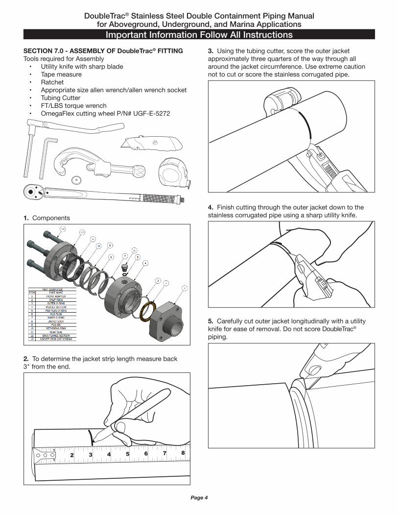
SECTION 7.0 - ASSEMBLY OF DoubleTrac® FITTINGTools required for Assembly
• Utility knife with sharp blade• Tape measure• Ratchet• Appropriate size allen wrench/allen wrench socket• Tubing Cutter• FT/LBS torque wrench• OmegaFlex cutting wheel P/N# UGF-E-5272
1. ComponentsNEWSECTION7.0(1.Components)Photo
9
2. To determine the jacket strip length measure back3" from the end.
1
12 3 4 5 6 7 8 9 10
3. Using the tubing cutter, score the outer jacketapproximately three quarters of the way through all around the jacket circumference. Use extreme caution not to cut or score the stainless corrugated pipe.
4. Finish cutting through the outer jacket down to the stainless corrugated pipe using a sharp utility knife.
5. Carefully cut outer jacket longitudinally with a utility knife for ease of removal. Do not score DoubleTrac® piping.

DoubleTrac® Stainless Steel Double Containment Piping Manualfor Aboveground, Underground, and Marina Applications
Important Information Follow All Instructions
Page 5
9. Remove all cap screws.
10. Separate the three sections of DoubleTrac® fitting.
11. Ensure that the Pusher Ring, Spiral Retaining Ring, and Square profile Rear Seal are installed within the back section of the fitting.
6. Remove portion of outer jacket.
CAUTION
NOTE: Inspect the stainless steel pipe for scoring from the tubing cutter. If the stainless steel pipe is damaged, remove the damaged portion and repeat this procedure.
7. DoubleTrac® field attachable fittings.
8. Loosen cap screws.

DoubleTrac® Stainless Steel Double Containment Piping Manualfor Aboveground, Underground, and Marina Applications
Important Information Follow All Instructions
Page 6
12. Inspect front section of DoubleTrac® fitting. • Ensure the fitting does not have any damage to npt
threads or front adaptor.
13. Remove split rings from middle section of DoubleTrac® fitting.
14. Inspect middle section of DoubleTrac® fitting • Ensure outer o-ring is not damaged or torn.
15. Ensure inner o-ring is not damaged or torn.
16. Ensure the beveled/tapered egde of jacket lock faces outward.
17. Prepare DoubleTrac® piping for final cut. Slide middle section of fitting into the DoubleTrac® pipe until it bottoms out.
18. Mark DoubleTrac® piping for final cut. Once the middle section of the fitting has bottomed out on piping, place one split ring half in the corrugation closest to the middle section of the fitting. Ensure split ring drops into first corrugation freely. Place a mark on top of the first two corrugations that are past the split ring.

DoubleTrac® Stainless Steel Double Containment Piping Manualfor Aboveground, Underground, and Marina Applications
Important Information Follow All Instructions
Page 7
CAUTION
Apply constant pressure on backside of fitting to ensure split rings do not come out of seat.
22. Insert cap screws into the back section of the fitting and tighten enough to allow the fitting to swivel. Swivel NPT front section into existing piping (elbow, tee, valve etc.).
CAUTION
NOTE: Do not use any pipe dope or thread sealants on the self-flaring connection. This connection is a metal to metal seat and will not seal properly if pipe dope or thread sealants are used. Sealants are to be used on the NPT Connector to the equipment only.
23. Tighten all cap screws in an alternating pattern.
Table 3DoubleTrac® Pipe Size Recommended Torque Values
DoubleTrac® Pipe Size Torque Settings
1" 30 FT-LBS
1-1/2" & 2" 50 FT-LBS
19. Remove middle section of DoubleTrac® fittting andcut through the corrugated piping using a tubing cutter with a sharp wheel. Cut must be centered in the valley between the two marked corrugations. Use full circular strokes in one direction and tighten roller pressure slightly after each revolution. DO NOT over tighten roller which may flatten tube.
CAUTION
Finishing the cut by bending or twisting may cause an improper seat.
CAUTION
NOTE: When making the final cut, do not cut DoubleTrac® with a reciprocating saw or hack saw.
20. Slide the back and middle section of the fitting onto the pipe and insert the split rings into the valley of the first corrugation closest to middle section of the fitting.
21. Slide the back and middle section of the fitting up until the split rings are covered by fitting.

DoubleTrac® Stainless Steel Double Containment Piping Manualfor Aboveground, Underground, and Marina Applications
Important Information Follow All Instructions
Page 8
SECTION 8.0 - DISASSEMBLY OF DOUBLETRAC® FITTING
1. Loosen the cap screws using a ratchet and theappropriate size hex driver.
2. Pry off fitting front adaptor using a flat tip screwdriver or flat pry bar. CAUTION
NOTE: Use extreme care.
3. Remove all cap screws.
4. Pry the back section of the DoubleTrac® fittingusing a flat tip screwdriver or flat pry bar.
5. Once the back section is pried apart from the middlesection of DoubleTrac® fitting, slide the back section farenough away to allow the middle section of DoubleTrac®
fitting to slide back exposing the split rings.
6. With the split rings exposed, remove split rings from DoubleTrac® fitting.
DoubleTrac® Stainless Steel Double Containment Piping Manualfor Aboveground, Underground, and Marina Applications
Important Information Follow All Instructions
Page 9
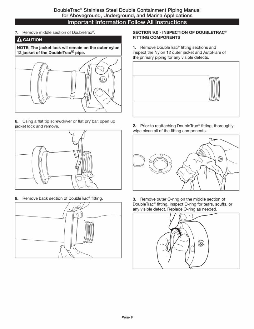
7. Remove middle section of DoubleTrac®. CAUTION
NOTE: The jacket lock wll remain on the outer nylon 12 jacket of the DoubleTrac® pipe.
8. Using a flat tip screwdriver or flat pry bar, open up jacket lock and remove.
9. Remove back section of DoubleTrac® fitting.
SECTION 9.0 - INSPECTION OF DOUBLETRAC® FITTING COMPONENTS
1. Remove DoubleTrac® fitting sections andinspect the Nylon 12 outer jacket and AutoFlare ofthe primary piping for any visible defects.
2. Prior to reattaching DoubleTrac® fitting, thoroughly wipe clean all of the fitting components.
3. Remove outer O-ring on the middle section of DoubleTrac® fitting. Inspect O-ring for tears, scuffs, or any visible defect. Replace O-ring as needed.

DoubleTrac® Stainless Steel Double Containment Piping Manualfor Aboveground, Underground, and Marina Applications
Important Information Follow All Instructions
Page 10
4. Remove inner O-ring on the middle section of DoubleTrac® fitting. Inspect O-ring for tears, scuffs, or any visible defect. Replace O-ring as needed.
5. Wipe jacket lock off and inspect for any visible defect.
6. Wipe the split rings off and inspect for any visible defect.
7. Insert jacket lock into the middle section of DoubleTrac® fitting.
CAUTION
NOTE: Beveled/tapered edge of jacket lock must face outward toward the back section of DoubleTrac® fitting.
8. Reinstall inner O-ring. Apply an ample amount ofclean bearing grease or lithium grease to inner O-ring.
9. Reinstall outer O-ring. Apply an ample amount ofclean bearing grease or lithium grease to outer O-ring.

DoubleTrac® Stainless Steel Double Containment Piping Manualfor Aboveground, Underground, and Marina Applications
Important Information Follow All Instructions
Page 11
10. Use clean bearing grease or lithium grease to coat the interior surface of DoubleTrac® fitting front adaptor.
11. The DoubleTrac® fitting is ready to reinstall. Followassembly of DoubleTrac® fitting instructions beginning on page 4 of the DoubleTrac® Design and Installation Guide.
SECTION 10.0 - TIGHTNESS TESTING OF DOUBLETRAC® PIPING
TIGHTNESS TESTING OF SECONDARY CONTAINMAINT PIPING
For tightness testing of DoubleTrac® piping, the secondary piping (Interstitial space) is pressurized with air up to 50 psig for a minimum of 30 minutes with no loss of pressure allowed. All joints must be wetted with a non-corrosive leak test solution and inspected for bubbles. The use of “soap” solutions are not permitted with stainless steel piping due to the corrosion potential of chlorinated compounds.
The installer must deliver a copy of the test results to the site owner or operator, who must keep a copy of all final test results.
NOTE: When testing the secondary, the primary is also being tested.
CAUTION
NOTE: When performing a tightness test, the piping must be completely isolated from the rest of the system.
0
10
20
3040 50
100
psi
0
10
20
3040 50
60
70
80
90
100
psi
TIGHTNESS TESTING OF PRIMARY PIPING
The piping system must be isolated from the tanks and subjected to a pipe tightness test on the primary and secondary piping.For tightness testing of DoubleTrac® piping, the primary piping is pressurized with air to a level of 1.5 times the maximum operating pressure of the system. Maintain this pressure for a minimum of one hour, making sure there is no drop in pressure.
NOTE: Before the piping system is backfilled, it must be isolated from the tanks and subjected to a pipe tightness test on the primary and secondary piping.

DoubleTrac® Stainless Steel Double Containment Piping Manualfor Aboveground, Underground, and Marina Applications
Important Information Follow All Instructions
Page 12
SECTION 11.0—DOUBLETRAC® CONTINUOUS MONITORING
Per UL 1369 requirements all Aboveground and Marinainstallations are required to have continuous secondarymonitoring. Prior to Installation of the DoubleTrac®
Continuous Monitoring System, Tightness Testing ofDoubleTrac® must be performed per page 11 of theDoubleTrac® Design and Installation Guide.Refer to page 16 for DoubleTrac® Continuous Monitoring Installation instructions.
SECTION 12.0—INSTALLATION OF CHECK VALVE
Once all testing has been completed, a check valve gets installed into the secondary port of DoubleTrac® fitting. CAUTION
NOTE: Do not overtighten check valve.
CAUTION
NOTE: If check valves are not installed, then the plug which originally came with the fitting must be installed. Prior to releasing for service, either a plug or check valve must be installed. Failure to do so voids all warranty.
SECTION 13.0—PIPE BURIAL, TRENCHING AND BACKFILL REQUIREMENTS
Provide a trench width equal to the pipe outer diameter plus six inches on each side. Separate multiple lines by at least 4 inches. The distance between any piping and the trench excavation walls must be at least 6 inches. For example, an installation of three 2" outer diameter pipes, the trench would be 26" wide and a minimum of 26" deep.
Whenever possible, product lines should be run in a single trench between the tank area and pump dispenser island area. Vent lines between the tank and the structure to which the aboveground vent lines are attached should also be installed in a single trench. Where more than one trench is required, piping should not cross over each other or cross over underground, aboveground and marina tanks.
The trench bottom must be sloped uniformly from the dispensers back to the tanks or sumps at a minimum slope of 1/8 inch per foot and be free of any sharp or protruding hard objects. In pressure systems, slope may not be necessary on supply lines. Rather, communication between the interstitial space of the secondary contained pressure supply lines and collection sumps should be maintained so that released product can enter a sump and be visually observed or detected by sensors. The trench bottom must be graded with a minimum of six inches of backfill such as washed sand, or pea gravel.
For backfilling, provide a minimum level of clean backfill between the top of the pipe and the surface as provided in Table 6.
Table 4
Surface PavementMin. Depth of
PavementMin. Level of Clean Backfill
Unpaved N/A 18"
Asphalt 2" 8"
Reinforced Concrete 4" 4"
CAUTION
Native back fill materials should never be used.

DoubleTrac® Stainless Steel Double Containment Piping Manualfor Aboveground, Underground, and Marina Applications
Important Information Follow All Instructions
Page 13
SECTION 14.0 – ROUTINE MAINTENANCE AND VISUAL INSPECTIONS - PROBLEMS
It is recommended that a visual inspection of all components as well as the inside of all containment sumps be completed at least once per month. Typical monthly inspections include, but are not limited to:• Visual inspection of piping: no visible damage to the outer jacket such as cracks, crushing, kinking, or puncture.• Visual inspection of all mounting hardware: all hardware must be intact and securely mounted in the original location.• Visual inspection of DoubleTrac® fittings: no visible
damage to fittings, no sign of leakage, all vent/test port fittings or bypass hoses should not show signs of crushing, kinking, or puncture.
Fuel leaks collected in containment sumps must be reported immediately and investigated by the site owner. If leakage or damage to the piping system is observed or suspected, OmegaFlex must be notified immediately. All sumps must be kept free of fuel, water and debris. When changing fuel filters at the dispenser, make sure any spilled product is cleaned out of the bottom of the dispenser sump to prevent possible fire hazard.
CAUTION
Ignoring or disabling leak detection alarms can lead to further damage and possible failure of the system.Failure to remove fuel and liquids from the containment sumps may compromise the performance and integrity of the sump and its associated fittings (entry fittings) and seals over prolonged periods of time.
SECTION 15.0 – OMEGAFLEX INC. CONTACT INFORMATIONOmegaFlex Inc. can be contacted if there are any questions concerning the installation, maintenance or repair of DoubleTrac® piping system. Please contact OmegaFlex customer service and 1-800-355-1035 or on the web at www.omegaflex.com or www.doubletrac.net.
SECTION 16.0 – PIPING GUIDE FOR ABOVEGROUND, UNDERGROUUND AND MARINA APPLICATIONS
Application BasicsAll installations must be performed by a trained operator. Typically each installation is unique and requires some level of review; however there are some general guidelines that are applicable to all installations. Inspect all piping, fittings and components when they arrive at the job site. Any piping that has been cut, crushed, or otherwise subjected to physical damage during transportation or storage shall be discarded and never used. The piping and fittings must be handled in such a manner that will not cause any unnecessary damage. Keep all components in the original packaging until ready for use. Inspect fittings prior to installation.
In particular, marinas have some specific requirements. Additionally, refer to the DoubleTrac® design and installation guide (DBT-001) for proper fitting assembly technique.
CONTINOUS MONITORING: Per UL1369, continuous interstitial monitoring for leak detection is MANDATORY.
DoubleTrac® piping continuous monitoring can be achieved by using DoubleTrac® P/N# UGF-CM-KIT. Refer to DoubleTrac® Continuous Monitoring Installation Instructions.

DoubleTrac® Stainless Steel Double Containment Piping Manualfor Aboveground, Underground, and Marina Applications
Important Information Follow All Instructions
Page 14
SECTION 17.0 – RECOMMENDED ENTRY FITTINGS FOR FLAT WALL SUMPS
OmegaFlex recommends the entry fittings shown in tables 5 and 6 to properly mate up with DoubleTrac® piping. These entry fittings have been evaluated for proper sizing. Other entry fittings may also be used based on compatibility. All entry fittings must meet local, state, and federal regulations for bulk petroleum storage and piping.
Recommended LinkSeal® for use in core drilled or cast holes.
Size LinkSeal® No.
1" LS-275-OS-316-8 Nitrile Seals
1-1/2" LS-300-OS-316-6 Nitrile Seals
2" LS-200-OS-316-9 Nitrile Seals
1" LS-275-LS-316-8 EPDM UV Seals
1-1/2" LS-300-LS-316-6 EPDM UV Seals
2" LS-200-LS-316-9 EPDM UV Seals
Table 7 - Recommended Link Seal®
Table 5 - Recommended Entry Fittings for Single Wall Sumps: Flat WallDoubleTrac®
Pipe SizeO.D. Nom
Bravo Part No.
Diversified Part No.
Chase Pipe Fitting
Omegaflex Part No.
Diversified Products – Fiberglass Rigid Entry
Fitting - Flat Walls
1" 1.55 F-10-OFLX-CR3.5 B 3.5-1.6 UGF-OFDT-B6-1.6 UGF-EF-16 OF PF-FGT-2.5-1.6
1-1/2" 2.30 F-15-OFLX-CR5 B 3.5-2.4 UGF-OFDT-B6-2.4 UGF-EF-24 OF PF-FGT-4.5-2.3
2" 2.93 F-20-OFLX-CR5 B 5-3.0 UGF-OFDT-B6-3.0 UGF-EF-32 OF PF-FGT-4.5-3.0
Table 6 - Recommended Entry Fittings for Double Wall Sumps: Flat WallDoubleTrac®
Pipe SizeO.D. Nom
Bravo Part No.
Diversified Products Part No.
Diversified Products – Fiberglass Rigid Entry
Fitting - Flat Walls
1" 1.55 F-10-OFLX-D-CR3.5 U8M-1.6 OF PF-FGT-2.5-1.6
1-1/2" 2.30 F-15-OFLX-D-CR5 U8M-2.4 OF PF-FGT-4.5-2.3
2" 2.93 F-20-OFLX-D-CR5 U8M-3.0 OF PF-FGT-4.5-3.0

DoubleTrac® Stainless Steel Double Containment Piping Manualfor Aboveground, Underground, and Marina Applications
Important Information Follow All Instructions
Page 15
SECTION 18.0 – INDOOR/OUTDOOR PIPE CLAMPING AND INSTALLATION
When installed indoor/outdoor, the DoubleTrac® piping must be adequately protected from puncture, shear, crush or other physical damage threats, including possible damage from:• vehicular or pedestrian traffic• corrosion• twisting, bending, kinking, chafing, and excessive prolonged movement of the piping• construction and excavationWhen installed along the inside/outside of a structure in an exposed condition, the DoubleTrac® piping shall be installed in a location which will not subject the piping to mechanical damage. NOTE: For support and protection, OmegaFlex recommends that inside/outside runs along the side of a building be clamped securely to the wall or other structural component per Table 7. Typical supports are Unistrut conduit hangers, “U” bolts, PVC pipe couplers, or Hosebuns.
Table 7 - Clamp SpacingDoubleTrac® Maximum Clamp Spacing
Horizontal Vertical
1" 6ft maxAll sizes of Doubtrac® Clamped every floor not to exceed 15ft1-1/2" 8ft max
2" 10ft max
NOTE: for floating docks piping must be supported evenly along the entire run with clamp spacing a minimum of every 3 feet.
SECTION 19.0 – MARINA PIPE CLAMPING AND INSTALLATIONFixed DockWhen installing DoubleTrac® on a fixed dock, the piping may be run along the side or underneath it. In either case, the routing must be such that it cannot be damaged, crush, or kinked during normal use of the dock. The piping must be supported evenly along the entire run; supports are required per Table 7. Typical supports are Unistrut conduit hangers, “U” bolts, PVC pipe couplers, or Hosebuns.Floating DockFloating docks are unique and require OmegaFlex Engineering to determine if DoubleTrac® can be used along the gangway. In many cases DoubleTrac® can be used along the gangway because the tidal surge is not significant enough to cause fatigue or premature failures.When OmegaFlex Engineering determines DoubleTrac® cannot be used along the gangway, the dock to shore connection should be an approved flexible connector. DoubleTrac® can be installed along the length of the floating dock portion. The routing must be such that DoubleTrac® cannot be damaged, kinked, or crushed during normal use of the dock. The piping must be supported evenly along the entire run; supports are required a minimum of every 3 feet. Typical supports are dock structure, built-in troughs, Unistrut pipe clamps, "U" bolts, pipe loop hangers, PVC pipe, or Hosebuns.
CAUTIONPlease contact OmegaFlex Engineering Department for flexible double contained dock connectors at 1-800-355-1039.
CAUTION
DoubleTrac® field attachable fittings MUST NEVER be submerged under water!
1
1
2
2
3
3
4
4
A A
B B
C C
D D
SIZE DWG NO REV
SCALE SHEET OF
DRAWN
APRD
TITLE451 Creamery Way, Exton, PA 19341-2509
Manufacturer of Flexible Metal Hose and Gas Piping Products
See DrawingMATERIAL
TOLERANCES x.xx 0.010x.xxx 0.005Fractions 1/64Angles 2Edge Break 0.002 - 0.005Max Radius Machined Corners R0.010All Diameters Concentricity 0.010 TIRMachined Surfaces
NOTICE - PROPRIETARY INFORMATION This drawing is the property of OmegaFlex, Inc. and must be returned without reproduction or duplication,at any time upon request but in any event as soon has it has served the purposes for which it is furnished.While in possesion of the recipient, it must be properly safeguarded against disclosure to anyone except
those employees who require it for work or job. The recipient must keep confidential and required his (its)employees to keep the information contained hereon.
DRAWING FILE:MODEL FILE:
125
DOUBLETRAC CLAMPING SYSTEM
DT CLAMP VIEW
1 2 BC
BGB 1/19/2016
BGB
AUTODESKINVENTOR
K:\CAD\DOUBLETRAC\CLAMPS\DT CLAMP VIEW.iamK:\CAD\DOUBLETRAC\CLAMPS\DT CLAMP LAYOUT REV B.idw
4-6 FT
DOUBLETRAC CLAMPING SYSTEM
SIZE PART NUMBER
1" UGF-32625T61
1-1/2" UGF-32625T26
2" UGF-32625T75
1 5/8" Unistrut
UGF-FSP-XX
DoubleTrac® Clamping System
Size Part Number
1" UGF-DTSC-16
1-1/2" UGF-DTSC-24
2" UGF-DTSC-32

DoubleTrac® Stainless Steel Double Containment Piping Manualfor Aboveground, Underground, and Marina Applications
Important Information Follow All Instructions
Page 16
SECTION 20.0—DOUBLETRAC® CONTINUOUS MONITORING INSTALLATION INSTRUCTIONS
Per UL 1369 requirements all Above Ground and Marina installations are required to have continuous secondary monitoring. Prior to Installation of the DoubleTrac®
Continuous Monitoring System, Tightness Testing of DoubleTrac® must be performed per page 11 of the DoubleTrac® Design and Installation Guide.
UGF‐CM‐KIT (1) Alarm (2) Fuel Sensors (2) Fuel Sensor Housings (2) Secondary Monitoring Shrader Hoses
PRODUCT DESCRIPTIONThe DoubleTrac® Continuous Monitoring System is designed to provide visual and audible alarms whenever a secondary leak is detected in the fuel sensor housing. The system is capable of utilizing a maximum of three weighted float switches and consists of an enclosure weatherproof to an IP54 standard. The weatherproof enclosure contains the visual and audible alarms and the electronic PCB.This alarm is approved to operate with flammable liquids classed as category 1, 2 or 3 in accordance with European Regulation No. 1272/2008. It is ATEX certified in accordance with EN 60079-0:2012 and EN 60079-11:2012. It is also IECEx certified in accordance with IEC 60079-0:2011 Ed 6 and IEC 60079-11:2011 Ed 6.The alarm box, featuring the warning devices and test/mute buttons, must be located outside any hazardous zone and bears the following certification marking and number:
Image1
Image2
The float sensor(s) can be located in hazardous zones 0,1 or 2 and bears the following certification marking and number:
Image1
Image2CONDITIONS OF CERTIFICATION
1. Due to safety critical internal creepage and clearancedistances in the control unit, if installed in a location other than a clean and dry environment, the user shall ensure that the control unit is additionally provided with protection having an ingress protection rating of at least IP54 and is maintained throughout the lifetime of the equipment.
2 The float switch incorporates an isolated metal partwhich could become either charged in use or be a discharge point for charged liquids upon filling or emptying. The float switch shall only be used in applications where static generated via contact liquids are controlled so not to be considered an ignition source.
3. The relay contacts in normal operation shall not switch more than 5Amps, 250V or 100VA max in accordance with IEC 60079-11:2011 Clause 6.3.14.
IMPORTANT WARNING NOTES
1. This alarm is designed for use with liquids classed as category 1, 2 or 3 in accordance with European Regulation No. 1272/2008, including petrol, diesel, gas oil, water, hydraulic oil and heating oil.
2. The alarm box featuring the warning devices and test/mute buttons must not be installed in a hazardous zone or below ground level. The float sensor can be located in zones 0, 1 or 2 with the supplied connecting wire running to the alarm box.
3. The user must ensure that chemicals present in the atmosphere do not affect the performance or degrade the polycarbonate enclosure.
4. Only the correct ATEX/IECEx certified float switches supplied by OmegaFlex® can be used with the Tank Alarm.
5. Installation of this equipment and its associated tank, pipe work and fittings must be carried out by a qualified installer.
Continuous Monitoiring Alarm
Fuel Sensor HousingFuel Sensor Housing
Fuel Sensor
Secondary Monitoring
Shrader Hose
Secondary Monitoring
Shrader Hose
Fuel Sensor
WARNINGS

DoubleTrac® Stainless Steel Double Containment Piping Manualfor Aboveground, Underground, and Marina Applications
Important Information Follow All Instructions
Page 17
6. The installation must be carried out in accordance with the requirements of EN 60079-14 the latest relevant electrical and local authority regulations and standards.
7. It must not be used with any liquids or applicationsother than those specified. OmegaFlex® will not accept warranty claims or liability if it is used for other liquids or applications.
8. This product must not be used if it is damaged.
SPECIFICATIONS- 115VAC 3-channel alarm.- IP54 weatherproof enclosure, for outside mounting.- Each channel can be used as an overfill, low level or
bund alarm.- High power alarm sounder.- High visibility flashing zenon beacon.- Test button checks float switches as well as beacon
and sounder.- Continuous Monitoring Alarm will draw
approximately 0.44 Amps or 48.4 Watts @110 VAC when in full alarm mode
INSTALLATION INSTRUCTIONS
CONTINUOUS MONITORING ALARM ENCLOSUREThe DoubleTrac® Continuous Monitoring Alarm enclosure must be mounted outside any hazardous zone(s). The Fuel Sensors are supplied with 16 feet of 2-core PUR fuel resistant cable and may be extended up to 325 feet.
1. Remove front display lid from alarm box and disconnect ribbon cable. Place the lid somewhere clean and safe.
L N EAC MAINS IN
SENSOR CONFIGURATIONDIP SWITCHES
OFF ON
NORM INVERT
123
123
RELAY RELAY RELAY
THESE TERMINALSCONNECT TO
INTRINSICALLYSAFE CIRCUITS
FUSE
ON
23
1
SDA03
ON
23
1
SDA03
NC C NOALARM 1
NC C NOALARM 2
NC C NOALARM 3
FLOAT SENSORCONNECTIONS
1 2 3
2. Use mounting holes to mount alarm enclosure into position.
WARNING
The DoubleTrac® Continuous Monitoring Alarm enclosure must be mounted outside any hazardous zone(s).
L N EAC MAINS IN
SENSOR CONFIGURATIONDIP SWITCHES
OFF ON
NORM INVERT
123
123
RELAY RELAY RELAY
THESE TERMINALSCONNECT TO
INTRINSICALLYSAFE CIRCUITS
FUSE
ON
23
1
SDA03
ON
23
1
SDA03
NC C NOALARM 1
NC C NOALARM 2
NC C NOALARM 3
FLOAT SENSORCONNECTIONS
1 2 3
POWER SUPPLYThe OmegaFlex® DoubleTrac® Continuous Monitoring Alarm (TA3A.PR.110) is designed to have a continual 120VAC supply fused at a rating of 6 amps max.
1. Remove rubber plug on enclosure and install a liquidtight conduit fitting. Run the main power supply lines into the enclosure.
WARNING
Ensure power is shut off at the Breaker prior to performing any electrical work within the housing enclosure.
2. Connect power supply lines to the "Live Mains" terminals as shown in the Connections Diagram.
CONNECTIONS DIAGRAM
L N ELIVE MAINS IN THIS AREA
SENSOR CONFIGURATIONDIP SWITCHES
OFF ON
NORM INVERT
123
123
RELAY RELAY RELAY
THESE TERMINALSCONNECT TO
INTRINSICALLYSAFE CIRCUITS
FUSE
ON
23
1
SDA03
ON
23
1
SDA03
NC C NOALARM 1
NC C NOALARM 2
NC C NOALARM 3
FLOAT SENSORCONNECTIONS
1 2 3

DoubleTrac® Stainless Steel Double Containment Piping Manualfor Aboveground, Underground, and Marina Applications
Important Information Follow All Instructions
Page 18
FUEL SENSOR AND FUEL SENSOR HOUSING INSTALLATION
1. Place Fuel Sensor Housing mounting bracket over housing thread.
2. Feed Fuel Sensor wire through the bulkhead fitting located on the Fuel Sensor housing cap. Install sensor into the housing and ensure sensor is resting on the bottom of the housing.
3. Using a pipe wrench, tighten the Fuel Sensor Housing cap.
4. Mount the assembled Fuel Sensor Housing near the DoubleTrac® end fitting.
5. Install Secondary Monitoring Schrader Hose into the housing cap bulkhead fitting. Tighten both housing cap fittings.
6. Install and tighten male Schrader valve adapter into the DoubleTrac® end fitting.
7. Attach Fuel Sensor housing hose to the DoubleTrac® end fitting.

DoubleTrac® Stainless Steel Double Containment Piping Manualfor Aboveground, Underground, and Marina Applications
Important Information Follow All Instructions
Page 19
CHANNELACTIVATION
FLOAT SWITCHSETTING
OFF ON NORM INVERT(HIGH LEVEL) (LOW LEVEL)
1
2
3
1
2
3
8. Repeat the Fuel Sensor and Fuel Sensor Housing Installation procedures if an additional fuel sensor is being installed on the opposite end fitting. If only using one fuel sensor then ensure DoubleTrac® secondary plug on opposite end fitting is installed and tightened.
9. Feed the Fuel Sensor wire through the bulkhead fitting attached to the Continuous Monitoring Alarm enclosure. Attach both leads of the Fuel Sensor to the corresponding Fuel sensor terminals and tighten the bulkhead fitting.
L N EAC MAINS IN
SENSOR CONFIGURATIONDIP SWITCHES
OFF ON
NORM INVERT
123
123
RELAY RELAY RELAY
THESE TERMINALSCONNECT TO
INTRINSICALLYSAFE CIRCUITS
FUSE
ON
23
1
SDA03
ON
23
1
SDA03
NC C NOALARM 1
NC C NOALARM 2
NC C NOALARM 3
FLOAT SENSORCONNECTIONS
1 2 3
NOTE
The Continuous Monitoring Alarm can accommodate up to three Fuel Sensors.
WARNING
Replace the unused bulkhead fittings with rubber grommets to prevent moisture from entering the enclosure.
DIPSWITCH SETTINGS
1. Switch on the corresponding channel activation dip switch for each Fuel Sensor that is installed.
2. Ensure that all float switch settings are switched to the Normal (High Level) setting.
EXTERNAL RELAY OUTPUTSThe relay contacts are rated at 5Amps, 250V or 100VA max. The relays are a switch only and do not offer a power source for external equipment. The relays are to be used to deactivate the pump control system, however they must not be used to directly switch the electrical load of the pump. If wiring an individual fuel sensor to an individual pump, the Normally Closed or Normally Open terminals of the relay can be utilized to deactivate the pump control system. If using multiple fuel sensors for one pump the output relays must be wired in series using the Normally Closed output terminals. This will ensure a high level alarm triggered by either float switch will deactivate the pump control system.
1. Run the pump control signal wire(s) through a liquid tight conduit fitting and into the DoubleTrac® Continuous Monitoring Enclosure.
2. Connect the signal wire(s) to the internal relay terminals based on the specific sensor/pump configuration. The specific sensor/pump configuration is based on the number of float sensors used and the number of pumps being controlled. Below are typical relay signal wiring schematics based on different sensor/ pump configurations.
NC C NO NC C NO NC C NO
Incoming and outgoing signal wire for (1) float sensor monitoring (1) pump

DoubleTrac® Stainless Steel Double Containment Piping Manualfor Aboveground, Underground, and Marina Applications
Important Information Follow All Instructions
Page 20
3. Ensure that the pump control signal wires are properly connected to the external pump control system. When properly connected a high level alarm triggered by the float sensors will cause the pump control system to deactivate the pump.
WARNING
The relays within the Continuous Monitoring Alarm enclosure must not be used to directly switch the electrical load of the pump.
COMPLETION OF INSTALLATION
1. Refit lid to alarm enclosure ensuring that the ribbon cable is reconnected to the main PCB and that the lid seal is in place.
2. Apply the self-adhesive "LEAK" product labels alongside the corresponding channel LED indicator on the front of the alarm housing.
3. Switch on power to the unit. The green "POWER LED" will illuminate to verify power is being supplied.
4. Overview of completed installation.
OPERATION
POWER STATUSThe Power LED will remain illuminated to indicate that there is power to the unit
ALARM CONDITIONWhen a high-level alarm condition occurs the corresponding channel LED on the Continuous Monitoring Alarm enclosure lid will illuminate and the sounder/beacon and external relay will activate.
FLOAT SWITCH FAULT INDICATIONIf any of the channel LEDs flashes repeatedly then this indicates a fault with the fuel sensor (float switch).
ALARM MUTEPressing the mute button for 1.5 seconds will silence the sounder when an alarm condition is occurring, the beacon will continue to flash until the alarm condition has been rectified. This will not de-activate any relays. The relays will only be de-activated when float switch returns to its normal position.If the mute button is not depressed the sounder will silence after 20 minutes leaving the beacon and channel LED on.The channel LED will remain on until the alarm condition has been rectified (float switch returns to its normal position).
ALARM TESTTo test the Tank Alarm, push and hold the test button on the lid. If the Tank Alarm is functioning correctly the sounder should activate, the beacon will flash and all activated channel LEDs will illuminate.If any of the channel LEDs flashes repeatedly then this indicates a fault with the float switch.
NC C NO NC C NO NC C NO
Incoming and outgoing signal wire for (2) float sensors monitoring (1) pump

DoubleTrac® Stainless Steel Double Containment Piping Manualfor Aboveground, Underground, and Marina Applications
Important Information Follow All Instructions
Page 21
ALARM DIMENSIONS
ALARM VIEW 1Tank alarm lid with all components - MAINS
4Tank alarm test button
5Tank alarm mute button
6Tank alarm box (base only)
2Alarm amber beacon
3Tank alarm sounder
TA3A.P (120V AC) - SHOWN
6.42”163mm
98mm6.42”
4.53”115mm
8.46”220mm
250mm9.84”

DoubleTrac® Stainless Steel Double Containment Piping Manualfor Aboveground, Underground, and Marina Applications
Important Information Follow All Instructions
Page 22
SECTION 21.0—RIGID ENTRY FITTING ATTACHMENT INSTALLATION INSTRUCTIONS
Components for the Rigid Entry fittingIncluded with fittingRigid Entry Fitting P/N/# UGF-EF-(16, 24, or 32)60 Grit Sandpaper
Required AccessoriesEpoxy Applicator Gun P/N# DF-APGUN-50HDEntry Fitting Cleaner P/N# UGF-EF-CLR50ML Epoxy Bonder P/N# UGF-EPB-50
Assemble the rigid entry components in order on the DoubleTrac pipe entering the sump:1. Threaded body2. Rubber ring3. Plastic ring4. Internal compression nut*Internal locking ring (only component that does not slide onto pipe)
NOTE
For ease of system installation, DO NOT glue entry fittings to enclosure until the DoubleTrac Piping system has been installed and tightness testing has been completed.
Instructions1. Attach DoubleTrac® NPT adaptor to ancillary
equipment (e.g. tee, 90, ball valve). Square the bolt holes to the ancillary equipment.
2. Find the center of your penetration point and drill your hole using a hole saw (see Table 1 for size).
3. Rough cut DoubleTrac® pipe and prep the end according to the latest DoubleTrac® D&I guide
4. Sand approx. 2” perimeter around interior and exterior of your hole saw cut, sand all of the surfaces of the entry fitting and DoubleTrac® pipe marked with an arrow (see Figure A).
5. Use the cleaner to clear debris from all the sanded surfaces and the locking ring/threaded body where it makes contact with the mounting surface.
6. Assemble rigid entry fitting components on DoubleTrac® pipe (see Figure A).
7. Assemble DoubleTrac® fitting according to the latest DoubleTrac® D&I guide with the internal locking ring placed on the ancillary equipment (see figure B).
Figure A
12
34
*
Figure B
INTERNAL RIGIDENTRY LOCKING RING
Table 1
Pipe Size Hole Saw Size1" 3-1/2"
1-1/2" 5"
2" 5"
SUMPINTERIOR
SUMPEXTERIOR

DoubleTrac® Stainless Steel Double Containment Piping Manualfor Aboveground, Underground, and Marina Applications
Important Information Follow All Instructions
Page 23
8. Prior to gluing DoubleTrac entry fitting to sump wall, follow the DoubleTrac Design and Installation Guide; Tightness Testing of Secondary Containment Piping.
9. Use epoxy bonder cartridge with the applicator gun to cover the serrated surface of the threaded body and internal locking ring and tighten both down to the sump wall (for stainless steel sumps there is a Viton gasket to be used in place of the epoxy in this step).
10. Tighten rigid entry compression nut onto the threaded body (see figure C).
11. Use epoxy bonder cartridge with the applicator gun to fill all three ports on the threaded body until the ports are visibly full (see figure D).
12. Use any remaining epoxy bonder to “caulk” any seams or contact surfaces.
13. Smooth any extra epoxy bonder to create a continuous seal on all seams and contact surfaces.
Figure C
Figure D

DoubleTrac® Stainless Steel Double Containment Piping Manualfor Aboveground, Underground, and Marina Applications
Important Information Follow All Instructions
Page 24
SECTION 22.0—DOUBLETRAC® CHASE PIPE ENTRY FITTING INSTALLATIONTools and Components:
Required accessories not included with Chase Pipe Entry Fitting: 1. 6" Hole Saw 2. 5/16" Nut Driver/Drill 3. Part No. UGF-EF-CLR (Chase Pipe Entry Fitting Cleaner) 4. Part No. UGF-APGUN-50HD (50ml Heavy Duty
Application Gun) 5. Part No. UGF-EPB-50 (Epoxy Bonder) 6. Sand Paper
Chase Pipe Fitting Parts:DoubleTrac® Size Chase Pipe Entry Fitting P/N#
1" UGF‐OFDT‐B6‐1.61‐1/2" UGF‐OFDT‐B6‐2.4
2" UGF‐OFDT‐B6‐3.0
Chase Pipe
Chase Pipe Crush Guard Rubber Boot
Chase Pipe Entry Fitting Body Chase Pipe Entry Fitting Locking Nut
Rubber Clamping Ring
1. Drill through sump wall using a 6" hole saw.
2. Sand 1-1/2" around the throughput hole on interior and exterior of sump.
3. Clean all surfaces using Part No. UGF-EF-CLR and allow to dry.
4. Apply an ample amount of Part No. UGF-EPB-50 bonder to the Ribbed Sealing surface of entry fitting. Ensure enough bonder is used for complete coverage.
5. Install the body of the Chase Pipe Entry Fitting through the sump wall.
6. On the interior of sump thread locking nut onto entry fitting body. Use a Pipe Wrench to tighten locking nut until snug.
CAUTION
Do not overtighten locking nut.
EPOXY
1.6.2.
3.
4.
5.

DoubleTrac® Stainless Steel Double Containment Piping Manualfor Aboveground, Underground, and Marina Applications
Important Information Follow All Instructions
Page 25
7. Trim face of chase pipe evenly in the valley of a corrugation. Install rubber clamping ring into the valley after the first corrugation. Slide chase pipe into entry fitting until the face of the rubber clamping ring is flush with the face of the chase pipe entry fitting body.
8. Insert DoubleTrac® piping through chase pipingto the center point of sump. Insert Chase Pipe CrushGuard into the inside of chase piping.
9. Ensure Rubber Clamping Ring is aligned under the Rubber Boot band clamp per Assembled Chase Pipe Cross Section View. Slide Rubber Boot over DoubleTrac® piping and ensure the Rubber Boot bottoms out onto the rubber edge of the entry fitting.
10. Use a 5/16" Nut Driver/Drill to tighten the band clamps.
CAUTION
Do not overtighten band clamps.
11. Refer to Page 4 of the DoubleTrac® Design and Installation Guide for instructions on how to installDoubleTrac® Field Attachable fitting.
Assembled Chase Pipe Cross Section View:
Chase Pipe Entry Fitting Locking NutChase Pipe Entry Fitting Body
Chase PipeDoubletrac Piping
Rubber Clamping RingChase Pipe Crush Guard
Rubber Boot

DoubleTrac® Stainless Steel Double Containment Piping Manualfor Aboveground, Underground, and Marina Applications
Important Information Follow All Instructions
Page 26
SECTION 23.0 – LIMITED WARRANTY- Aboveground and Marina
PRODUCT LENGTH OF WARRANTY
DoubleTrac® petroleum pipe & fittings 15 years
Omega Flex, Inc. warrants to the purchaser of the DoubleTrac® piping system that the products listed above (the “Product”) when installed in above ground applications or on fixed or floating docks will be free from defects in material or workmanship for period stated above, as measured from the date of shipment from DoubleTrac®. This excludes DoubleTrac® dock connectors and entry fittings which are covered under a separate warranty.
If upon examination, the Product is shown to have a defect in material or workmanship during the warranty period, DoubleTrac® will, at its option, either repair or replace that part of the Product which is shown to be defective, or issue a credit for the amount of the defective product that may be applied to future orders of the Product.
This limited warranty does not apply: • If the Product has been subjected to misuse or neglect, has been accidentally or intentionally damaged, or has been altered or
modified in any way. • If the Product has been repaired by anyone who is not a DoubleTrac® authorized service representative. • If the Product has not been installed in accordance with the DoubleTrac® installation guidelines. • If the Product has been installed with unauthorized third party components, except those components that are recommended
for use with DoubleTrac® in the DoubleTrac® installation guide. • To any costs or expenses incurred during investigation, removal or reinstallation of the defective Product, including without
limitation any costs or expenses for clean-up, downtime, or lost profits. • To any damage or impairment of the Product caused by any casualty, including without limitation fires, storms, floods,
earthquakes, or acts of God. • To any workmanship of the installer of the Product.
This limited warranty is conditional upon: • Receipt of a written warranty claim during the applicable warranty period. • Installment of the Product by an individual who has received factory authorized training on the installation and proper use of
DoubleTrac®. • All site and warranty registration forms are completed and received by DoubleTrac® within 30 days of installation. • All piping and connections are installed with an approved leak detection device in each tank and dispenser sump. • A sump inspection log or EPA checklist is maintained and provided to DoubleTrac® on request. • DoubleTrac® receives notice of warranty claim within 24 hours of any known or suspected failure of the Product.
Product can only be returned with prior written approval from DoubleTrac®. All returns must be freight prepaid. Manufacturer will inspect the alleged defective part, and provide the customer with the results of that inspection whether or not in the reasonable opinion of DoubleTrac®, that there exists a defect in material or workmanship. Repair or replacement of any part under this Limited Warranty shall not extend the duration of the warranty with respect to such repaired or replaced part beyond the stated warranty period.
IMPORTANTThis limited warranty is in lieu of all other warranties, either express or implied, and all such other warranties, including without limitation implied warranties of merchantability or fitness for a particular purpose, are hereby disclaimed and excluded from this limited warranty.
LIMITATION OF LIABILITYIn no event will DoubleTrac® be liable in any way for (a) any consequential, special, or incidental damages of any nature whatsoever, or (b) any amounts in excess of the selling price of the Product or any parts thereof found to be defective.

DoubleTrac® Stainless Steel Double Containment Piping Manualfor Aboveground, Underground, and Marina Applications
Important Information Follow All Instructions
Page 27
SECTION 24.0 – LIMITED WARRANTY- Underground
PRODUCT LENGTH OF WARRANTY
DoubleTrac® petroleum pipe & fittings 30 years
Omega Flex, Inc. warrants to the purchaser of the DoubleTrac® piping system that the products listed above (the “Product”) when installed in underground applications will be free from defects in material or workmanship for period stated above, as measured from the date of shipment from DoubleTrac®. This excludes DoubleTrac® dock connectors and entry fittings which are covered under a separate warranty.
If upon examination, the Product is shown to have a defect in material or workmanship during the warranty period, DoubleTrac® will, at its option, either repair or replace that part of the Product which is shown to be defective, or issue a credit for the amount of the defective product that may be applied to future orders of the Product.
This limited warranty does not apply: • If the Product has been subjected to misuse or neglect, has been accidentally or intentionally damaged, or has been altered or
modified in any way. • If the Product has been repaired by anyone who is not a DoubleTrac® authorized service representative. • If the Product has not been installed in accordance with the DoubleTrac® installation guidelines. • If the Product has been installed with unauthorized third party components, except those components that are recommended
for use with DoubleTrac® in the DoubleTrac® installation guide. • To any costs or expenses incurred during investigation, removal or reinstallation of the defective Product, including without
limitation any costs or expenses for clean-up, downtime, or lost profits. • To any damage or impairment of the Product caused by any casualty, including without limitation fires, storms, floods,
earthquakes, or acts of God. • To any workmanship of the installer of the Product.
This limited warranty is conditional upon: • Receipt of a written warranty claim during the applicable warranty period. • Installment of the Product by an individual who has received factory authorized training on the installation and proper use of
DoubleTrac®. • All site and warranty registration forms are completed and received by DoubleTrac® within 30 days of installation. • All piping and connections are installed with an approved leak detection device in each tank and dispenser sump. • A sump inspection log or EPA checklist is maintained and provided to DoubleTrac® on request. • DoubleTrac® receives notice of warranty claim within 24 hours of any known or suspected failure of the Product.
Product can only be returned with prior written approval from DoubleTrac®. All returns must be freight prepaid. Manufacturer will inspect the alleged defective part, and provide the customer with the results of that inspection whether or not in the reasonable opinion of DoubleTrac®, that there exists a defect in material or workmanship. Repair or replacement of any part under this Limited Warranty shall not extend the duration of the warranty with respect to such repaired or replaced part beyond the stated warranty period.
IMPORTANTThis limited warranty is in lieu of all other warranties, either express or implied, and all such other warranties, including without limitation implied warranties of merchantability or fitness for a particular purpose, are hereby disclaimed and excluded from this limited warranty.
LIMITATION OF LIABILITYIn no event will DoubleTrac DoubleTrac® be liable in any way for (a) any consequential, special, or incidental damages of any nature whatsoever, or (b) any amounts in excess of the selling price of the Product or any parts thereof found to be defective.

DoubleTrac® Stainless Steel Double Containment Piping Manualfor Aboveground, Underground, and Marina Applications
Important Information Follow All Instructions
Page 28
SECTION 25.0 – LIMITED WARRANTY- Installation FormWarranty Disclaimer: The DoubleTrac® Limited Warranty is only valid if this form is received by the DoubleTrac® Customer Service
Team within 30 days after installation is complete.
Contractor Installation Site
Name ________________________________________________________ Name __________________________________________________
Address ______________________________________________________ Address ________________________________________________
Email _________________________________________________________
Phone ________________________________________________________ Installation Date _________________________________________
Fax __________________________________________________________ Completion Date _________________________________________
Distributor ____________________________________________________
Installer's State Certification No. _________________________________ Installer's Training Cert No.: ______________________________
Piping 1. What size DoubleTrac® piping was used? (Circle all that apply) 1" 1.5" 2"2. Installation type (Circle all that apply): Aboveground (Non-Marina) Aboveground (Marina) Underground3. Was DoubleTrac® piping system continuously monitored? (Circle one) Yes No
Please circle yes or no to the following:4. Was any other piping used other than DoubleTrac®? (Circle One) Yes No If so, what kind?_____________________________________________________________________________________________ ______5. What types of fuels are to be stored? (Circle all that apply) Gasoline Gasohol Diesel Ethanol Methanol Fuel Oil Bio-diesel Other_____________________________6. Was the site contaminated before installation? Yes NoIf yes: (a) Was the site fully remediated? Yes No (b) Did the site receive clearance from
government authorities? Yes No (c) What is the name of the environmental contractor?_________________________________________________________________ 7. Were all piping and fittings inspected for damage before and after installation? Yes No8. Was the DoubleTrac® Design and Installation Guide followed? Yes No9. Were all DoubleTrac® Fittings tightened to proper torque specifications? Yes No 10. Was any direct buried pipe crossed over? Yes No If so, were crossover supports used? Yes No11. Was the DoubleTrac® Interstitial Space pressure tested? Yes No12.Was the Secondary Jacket left open to atmosphere after testing? Yes No
Pipe Entry Points (please provide)Name of Entry Fitting Manufacturer ________________________________________________________________________________________All Entry Fitting part numbers______________________________________________________________________________________________
Dispenser Sumps (please provide)
Name of Dispenser Sump Manufacturer ____________________________________________________________________________________ All Dispenser Sump part numbers _________________________________________________________________________________________ Circle yes or no: Were sumps inspected for damage before and after installation? Yes NoWere the instructions followed? Yes No
Tank Sumps (please provide)Name of Tank Sump Manufacturer _________________________________________________________________________________________All Tank Sump part numbers ______________________________________________________________________________________________Contractor Signature _______________________________________________________________ Date ________________________________
OmegaFlex® 451Creamery Way • Exton PA 19341 • 800.355.1039 (Fax) 610.524.6484 • www.doubletrac.net

DoubleTrac® Stainless Steel Double Containment Piping Manualfor Aboveground, Underground, and Marina Applications
Important Information Follow All Instructions
Page 29
NOTES:

Omega Flex, Inc.451 Creamery Way, Exton, PA 19341-2509800-355-1039 • Fax 610-524-6484www.omegaflex.comISO 9001 Registered Company
© Omega Flex, Inc. 2021
Corporate Offices 13 Court Street, Suite 1001, Middletown, CT 06457860-704-6820 • Fax 860-704-6830
DBT-001 REV 08/21


