27
Stainless Steel in Contact with Other Metallic Materials Materials and Applications Series, Volume 10 Metal 1 Anode Metal 2 Cathode Electrolyte e -

Stainless Steel in Contactwith Other Metallic Materials
Materials and Applications Series, Volume 10Diamant Building · Bd. A. Reyers 80 · 1030 Brussels· Belgium ·Tel. +32 2 706 82-67 · Fax -69 · e-mail [email protected] · www.euro-inox.org
ISBN 978-2-87997-263-3
Metal 1Anode
Metal 2Cathode
Electrolyte
e-
C O N T A C T W I T H O T H E R M E T A L L I C M A T E R I A L S
Euro Inox
Euro Inox is the European market development asso-
ciation for stainless steel. Members of Euro Inox include:
• European stainless steel producers
• national stainless steel development associations
• development associations of the alloying element
industries
The prime objectives of Euro Inox are to create aware-
ness of the unique properties of stainless steel and to fur-
ther its use in existing applications and in new markets.
To achieve these objectives, Euro Inox organizes confer-
ences and seminars and issues guidance in printed and
electronic form to enable architects, designers, speci-
fiers, fabricators and end users to become more familiar
with the material. Euro Inox also supports technical and
market research.
Full members
Acerinoxwww.acerinox.es
Outokumpu www.outokumpu.com
ThyssenKrupp Acciai Speciali Terniwww.acciaiterni.com
ThyssenKrupp Nirostawww.nirosta.de
ArcelorMittal Stainless BelgiumArcelorMittal Stainless Francewww.arcelormittal.com
Associate members
Acroniwww.acroni.si
British Stainless Steel Association (BSSA)www.bssa.org.uk
Cedinoxwww.cedinox.es
Centro Inoxwww.centroinox.it
Informationsstelle Edelstahl Rostfreiwww.edelstahl-rostfrei.de
Institut de Développement de l’Inox (I.D.-Inox)www.idinox.com
International Chromium Development Association (ICDA)www.icdachromium.com
International Molybdenum Association (IMOA)www.imoa.info
Nickel Institutewww.nickelinstitute.org
Paslanmaz Çelik Derneği (PASDER)www.turkpasder.com
Polska Unia Dystrybutorów Stali (PUDS)www.puds.pl
SWISS INOXwww.swissinox.ch

1
C O N T A C T W I T H O T H E R M E T A L L I C M A T E R I A L S
Table of contents
1 Introduction 2
2 The principles of galvanic corrosion 3
3 Relevant factors and examples 5
3.1 Electrolyte resistance 5
3.2 Wetting duration and environments 6
3.3 The kinetics of electrode reactions 8
3.4 Cathode and anode area 8
4 Practical experience in different applications 10
4.1 Water and sewage treatment 11
4.2 Components in atmospheric conditions 14
4.3 Stainless steel in building and construction 15
4.4 Stainless steel in transport applications 18
Frequently asked questions 20
5 Preventing galvanic corrosion 22
6 Literature 23
Photo credits:
Atomium asbl / vzw, Brussels (B)
Centro Inox, Milan (I)
Bundesanstalt für Materialprüfung und -forschung,
Berlin (D)
David Cochrane, Sidcup (UK)
Benoît Van Hecke, Hasselt (B)
Outokumpu, Tornio (FIN)
Thomas Pauly, Brussels (B)
Christoph Seeberger, Munich (D)
ThyssenKrupp Nirosta GmbH, Krefeld (D)
Schöck Bauteile GmbH, Baden-Baden (D)
Viega GmbH & Co. KG, Attendorn (D)
Stainless Steel in Contact with Other Metallic Materials
Materials and Applications Series, Volume 10
ISBN 978-2-87997-263-3
© Euro Inox 2009
Translated and adapted from ARLT, N. / BURKERT, A /
ISECKE, B., Edelstahl Rostfrei in Kontakt mit anderen
Werkstoffen (Merkblatt 829), Düsseldorf, Informations-
stelle Edelstahl Rostfrei, 4th edition 2005
Publisher
Euro Inox
Diamant Building, Bd. A. Reyers 80,
1030 Brüssel, Belgium
Phone +32 2 706 82 65 Fax +32 2 706 82 69
Disclaimer
Euro Inox has made every effort to ensure that the infor-
mation presented in this document is technically correct.
However, the reader is advised that the material con-
tained herein is for general information purposes only.
Euro Inox, its members, specifically disclaim any liabili-
ty or responsibility for loss, damage, or injury, resulting
from the use of the information contained in this publi-
cation.
Copyright notice
This work is subject to copyright. Euro Inox reserves all
rights of translation in any language, reprinting, re-use of
illustrations, recitation and broadcasting. No part of this
publication may be reproduced, stored in a retrieval
system or transmitted in any form or by any means,
electronic, mechanical, photocopying, recording or
otherwise, without the prior written permission of the
copyright owner, Euro-Inox, Luxembourg. Violations may
be subject to legal proceedings, involving monetary
damages as well as compensation for costs and legal
fees, under Luxemburg copyright law and regulations
within the European Union.
2
C O N T A C T W I T H O T H E R M E T A L L I C M A T E R I A L S
1 Introduction
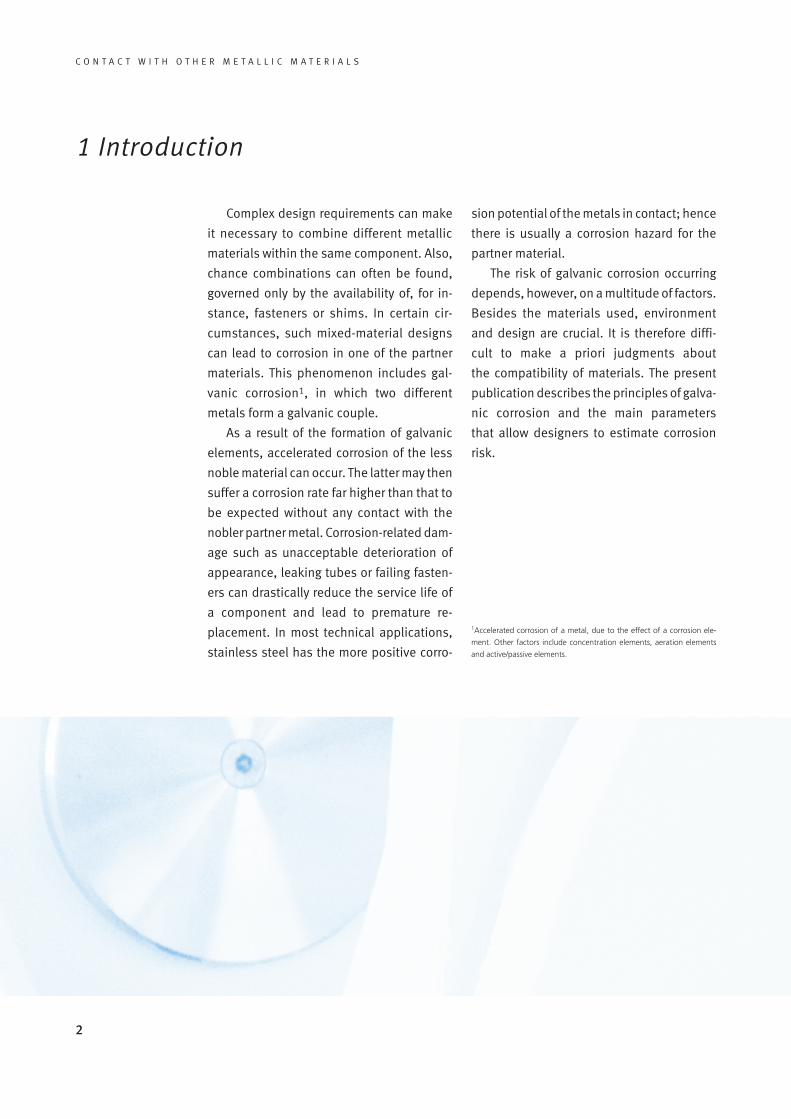
Complex design requirements can make
it necessary to combine different metallic
materials within the same component. Also,
chance combinations can often be found,
governed only by the availability of, for in-
stance, fasteners or shims. In certain cir-
cumstances, such mixed-material designs
can lead to corrosion in one of the partner
materials. This phenomenon includes gal-
vanic corrosion1, in which two different
metals form a galvanic couple.
As a result of the formation of galvanic
elements, accelerated corrosion of the less
noble material can occur. The latter may then
suffer a corrosion rate far higher than that to
be expected without any contact with the
nobler partner metal. Corrosion-related dam-
age such as unacceptable deterioration of
appearance, leaking tubes or failing fasten-
ers can drastically reduce the service life of
a component and lead to premature re-
placement. In most technical applications,
stainless steel has the more positive corro-
1Accelerated corrosion of a metal, due to the effect of a corrosion ele-
ment. Other factors include concentration elements, aeration elements
and active/passive elements.
sion potential of the metals in contact; hence
there is usually a corrosion hazard for the
partner material.
The risk of galvanic corrosion occurring
depends, however, on a multitude of factors.
Besides the materials used, environment
and design are crucial. It is therefore diffi-
cult to make a priori judgments about
the compatibility of materials. The present
publication describes the principles of galva-
nic corrosion and the main parameters
that allow designers to estimate corrosion
risk.

3
C O N T A C T W I T H O T H E R M E T A L L I C M A T E R I A L S
naturally occur in the metal in isolation; how-
ever, the corrosive attack on the anode is
greatly accelerated. In some cases, the for-
mation of galvanic elements can lead to cor-
rosion in materials that would otherwise be
corrosion resistant in the environment in
question. This can be the case for passive
materials such as aluminium, which can be
locally polarised in a certain environment. In
such cases, localised corrosion phenomena
such as crevice corrosion or pitting corrosion
can be observed, which would not have
occurred without the shift in potential
caused by the formation of galvanic ele-
ments.
For galvanic corrosion to occur, there
must be:
• different corrosion potentials of
the metals within a given system;
• a conductive connection between the
two metals;
• an electrically conductive humidity
film (electrolyte) connecting both
metals
Figure 1 shows the three prerequisites in
graphic form.
If galvanic corrosion occurs, the less no-
ble material – the anode – is preferentially
attacked whilst the more noble material –
the cathode – is even protected against
corrosion. In fact, the principle of cathodic
protection is based on sacrificial anodes
providing protection from corrosion.
The contact of two metals with different
potentials in an electrically conductive solu-
tion leads to a flow of electrons from the
anode to the cathode. The electro-chemical
reactions are the same as those that would
2 The principles of galvanic corrosion
Figure 1
shows the three prerequi-
sites in graphic form.
Electrolyte
Metal 1e–
Metal 2
Anode Cathode

4
C O N T A C T W I T H O T H E R M E T A L L I C M A T E R I A L S
Contrary to widespread belief, the differ-
ence of potential in an electrochemical cell
alone is not a good indicator of the actual
risk of galvanic corrosion. It only indicates
whether or not such a risk has to be taken
into account. In this context, it should be
remembered that the numerous published
tables of the standard potentials of metals
only provide an approximation of differences
of potential. The decisive factor is not the
difference of potential observed under stan-
dardised experimental conditions but rather
the actual difference of potential under real
operating conditions. This is why empirical
tables of galvanic series have been produced
for typical environments such as sea water.
These position the potential of various met-
als in a given environment (Figure 2).
Awareness of the prerequisites of gal-
vanic corrosion and a proper understanding
of the examples in Figure 3 make it possible
to determine preventive action, which will be
discussed in section 5.
GraphiteAlloy 625/ C-276
Superaustenitic stainless steel
Titanium
Alloy 400Austenitic stainless steel grade 1.4404 (316 L), passive
Nickel
Ni-Al Bronze90/10 Cupro-Nickel
Al-brassCopper
Austenitic stainless steel castingLead
Tin
Carbon steelCast steel
Al-2.7 Mg
ZincAluminium
Magnesium
-2000 -1500 -1000 -500 0 500
Potential (mV SCE)
Figure 2:
The Galvanic Series in
sea-water at 10 °C [11]
Figure 3:
Conditions in which
galvanic corrosion
cannot occur
(Metal 1 = Anode, Metal 2 = Cathode)
Metal 1 Metal 2 Metal 1 Metal 2 Metal 1 Metal 2 Metal 1 Metal 2
Insulator
ElectrolyteElectrolyte Electrolyte Electrolyte
… without electrically conductive joints
… in metals with no difference of potential
… without connection by an electrolyte
Coating
Galvanic corrosion cannot occur …

5
C O N T A C T W I T H O T H E R M E T A L L I C M A T E R I A L S
3 Relevant factors and examples
According to Faraday’s law, electro-chem-
ical corrosion processes are directly related
to charge transfer, i.e. the flow of currents.
Currents or current densities are therefore
frequently used to measure corrosion. If the
conditions for galvanic corrosion are met in
principle, the total corrosion current Itot is
composed of a partial current from self-
corrosion Is (i.e. the part of the corrosion that
is independent of contact with other materi-
als) and a partial cell current Iel (i.e. the part
of the corrosion due to the cell current be-
tween the partner materials (Equation 1).
Itot = Is + Iel (Equation 1)
Intensity of element corrosion is deter-
mined by the difference of potential between
the two metals (DU), the electrolyte resis-
tance (Rel) and the polarisation resistance at
the anode (Rp,a) and cathode (Rp,c) respec-
tively (Equation 2).
Iel = (Equation 2)
From this equation, inferences can be
drawn concerning the factors that determine
galvanic corrosion. These factors are critical
in determining whether or not metallic cor-
rosion will become a technically relevant
problem. The effects of these factors will
therefore be discussed individually.
3.1 Electrolyte resistance
The risk of galvanic corrosion diminishes
with increasing electrolyte resistance. This is
because the reach of the galvanic current is
reduced and the shift of potential at the an-
ode is limited, as illustrated in Figure 4.
Measurement of potential at the surface
identifies, in the case of an insulated anode,
the position of the respective potentials of
cathode and anode, independently of each
other. In the transition area, a marked jump
in potential is observed. If an electrically
conductive connection between cathode
and anode exists, a low polarisation of the
anode towards higher values is observed
in electrolytes with high resistance (such as
water films resulting from condensation). In
the case of electrolyte films of low resistance
(salt water), a very strong polarisation is
measured. The higher the polarisation, the
higher the corrosion rate of the anode if the
material is active or the higher the probabil-
ity of reaching critical (corrosion-initiating)
potential if the material is in its passive state.
Table 1 shows specific conductivity values of
various types of water.
AnodeAnodeAnodeAnode
Low resistance High galvanic corrosion
High resistance Low galvanic corrosion
Insulated anode
Cathode Anode Cathode
No galvanic corrosion
Figure 4:
Influence of electrolyte
resistance on anode
polarisation
U
x
DURel + Rp,a + Rp,c

6
C O N T A C T W I T H O T H E R M E T A L L I C M A T E R I A L S
Environment Specific conductivity in (V · cm)-1
Pure water 5 · 10-8
Demineralised water 2 · 10-6
Rain water 5 · 10-5
Drinking water 2 · 10-4 - 1 · 10-3
Brackish river water 5 · 10-3
Sea water 3,5 · 10-2 - 5 · 10-2
3.2 Wetting duration and environments
There is a strong interaction between
electrolyte resistance and duration of wet-
ting. This is of critical importance wherever
components are not permanently wetted by
watery liquids. As explained in the descrip-
tion of the prerequisites of galvanic corro-
sion, the electrolyte film plays a key role.
Without such a film, no galvanic corrosion
can occur. This implies that, in practice, any
combination of metallic materials is uncriti-
cal from a corrosion point of view if no elec-
trolyte film is present. This is typical of inte-
riors without condensation. In lighting
fixtures or interior-decoration components,
virtually any material combination can be
used, in normally aerated and heated envi-
ronments, without restrictions in terms of
corrosion risk (Figure 5).
Both length of exposure and electrolyte
resistance are strongly dependent on local
conditions. In marine, industrial or indoor
swimming pool environments, the probabil-
ity of galvanic corrosion is significantly high-
er than in rural atmospheric conditions.
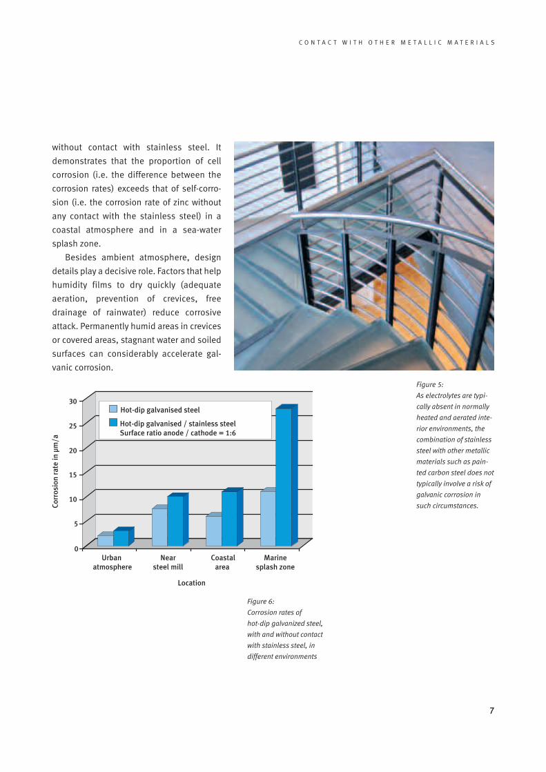
Figure 6 shows the influence of the environ-
ment on the corrosion rate of zinc, with andTable 1:
Typical values of specific
conductivity in different
types of water
7
C O N T A C T W I T H O T H E R M E T A L L I C M A T E R I A L S
Figure 5:
As electrolytes are typi-
cally absent in normally
heated and aerated inte-
rior environments, the
combination of stainless
steel with other metallic
materials such as pain-
ted carbon steel does not
typically involve a risk of
galvanic corrosion in
such circumstances.
Figure 6:
Corrosion rates of
hot-dip galvanized steel,
with and without contact
with stainless steel, in
different environments
Hot-dip galvanised steel
Hot-dip galvanised / stainless steelSurface ratio anode / cathode = 1:6
30
25
20
15
10
5
0Urban
atmosphereCoastal
areaMarine
splash zoneNear
steel mill
Location
Corr
osio
nra
tein
µm/a
without contact with stainless steel. It
demonstrates that the proportion of cell
corrosion (i.e. the difference between the
corrosion rates) exceeds that of self-corro-
sion (i.e. the corrosion rate of zinc without
any contact with the stainless steel) in a
coastal atmosphere and in a sea-water
splash zone.
Besides ambient atmosphere, design
details play a decisive role. Factors that help
humidity films to dry quickly (adequate
aeration, prevention of crevices, free
drainage of rainwater) reduce corrosive
attack. Permanently humid areas in crevices
or covered areas, stagnant water and soiled
surfaces can considerably accelerate gal-
vanic corrosion.

3.4 Cathode and anode area
A factor in the calculation of cell current
density, iel (area-related cell current) is the
ratio of cathodic (Ac) and anodic (Aa) surface
areas. It strongly influences the velocity of
galvanic corrosion (Equation 3).
iel = (Equation 3)
As long as the cathodic surface area (the
more noble metal of the galvanic couple) is
very small in comparison to the anodic sur-
face area (the less noble metal) no change in
corrosion behaviour is observed. This situa-
tion is shown in Figure 7.
8
C O N T A C T W I T H O T H E R M E T A L L I C M A T E R I A L S
3.3 The kinetics ofelectrode reactions
The kinetics of electrode reactions are
expressed in Equation 3 by the polarisation
resistance values of the anode and the
cathode. Differences in potential as low as
100 mV can lead to corrosion, while metals
with considerably higher differences of po-
tential can be joined without difficulty. In
fact, difference of potential provides no in-
formation about the kinetics of galvanic cor-
rosion. The kinetics of the reaction depend
on the metal. Titanium, for instance, reduces
dissolved oxygen much less readily than
copper. This explains why carbon steel cor-
rodes more quickly in contact with copper
than with titanium, although the latter has
higher positive potential than copper.
In this context, the formation of corrosion
layers also plays a decisive role. These can
significantly change the potential of a mate-
rial and be an obstacle to the anodic and/or
cathodic partial reaction.
Figure 7:
As the cathode (metal 2)
is small compared to
the anode (metal 1),
no damage is caused.
Metal 1 Metal 1
Metal 2
Electrolyte
DURel + Rp,a + Rp,c
Ac
Aa·
Stainless steel
Stainless steelGalvanized steel
Galvanized steel
Figure 8a, 8b:
Stainless steel fasteners
on much larger galvani-
zed steel components
do not normally cause
corrosion.

9
C O N T A C T W I T H O T H E R M E T A L L I C M A T E R I A L S
Typical examples can be found when
stainless steel fasteners are used on alu-
minium or galvanized carbon steel compo-
nents. Two practical applications are shown
in Figure 8. Even in corrosive conditions, this
material causes virtually no galvanic corro-
sion.
Under atmospheric conditions, it is
sometimes difficult to quantify the active
proportions of anodic and cathodic surfaces.
For a practical evaluation, this may, howev-
er, not be necessary. Normally it is sufficient
to consider the system in general. In materi-
al combinations, fasteners should always be
made of the more noble material, so the ca-
thodic surface is small.
The opposite situation, however, can
cause a problem. If a small anode is sur-
rounded by a large cathode, galvanic corro-
sion may occur, as shown in Figure 9.
Typical examples of such a situation are
shown in Figure 10. In these cases, it is clear
that, under corrosive conditions, the partner
metal may suffer accelerated corrosion.
Figure 9:
Galvanic corrosion
is likely to occur if
the anode (metal 1)
is small and the
cathode (metal 2)
is large
Metal 2 Metal 2
Metal 1
Electrolyte
Stainless steel
WoodGalvanized steel
Stainless steel
Galvanized steel
Figure 10a, 10b:
Practical examples of
the principle shown in
Figure 9 (galvanized
carbon steel in contact
with stainless steel, in
a marine atmosphere)
Figure 11:
To prevent galvanic cor-
rosion, only stainless
steel fasteners should be
used on stainless steel
panels.
10
C O N T A C T W I T H O T H E R M E T A L L I C M A T E R I A L S
4 Practical experience in different applications
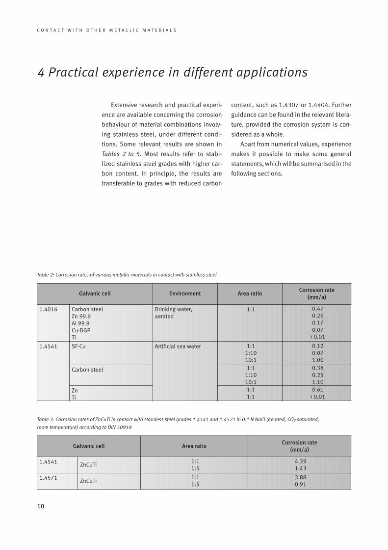
Extensive research and practical experi-
ence are available concerning the corrosion
behaviour of material combinations involv-
ing stainless steel, under different condi-
tions. Some relevant results are shown in
Tables 2 to 5. Most results refer to stabi-
lized stainless steel grades with higher car-
bon content. In principle, the results are
transferable to grades with reduced carbon
content, such as 1.4307 or 1.4404. Further
guidance can be found in the relevant litera-
ture, provided the corrosion system is con-
sidered as a whole.
Apart from numerical values, experience
makes it possible to make some general
statements, which will be summarised in the
following sections.
Galvanic cell Environment Area ratioCorrosion rate
(mm/a)
1.4016 Carbon steelZn 99.9Al 99.9Cu-DGPTi
Drinking water, aerated
1:1 0.470.260.170.07
< 0.01
1.4541 SF-Cu Artificial sea water 1:11:1010:1
0.120.071.00
Carbon steel 1:11:1010:1
0.380.251.10
ZnTi
1:11:1
0.61< 0.01
Galvanic cell Area ratioCorrosion rate
(mm/a)
1.4541 ZnCuTi1:11:5
4.391.43
1.4571 ZnCuTi1:11:5
3.880.91
Table 3: Corrosion rates of ZnCuTi in contact with stainless steel grades 1.4541 and 1.4571 in 0.1 N NaCl (aerated, CO2 saturated,
room temperature) according to DIN 50919
Table 2: Corrosion rates of various metallic materials in contact with stainless steel

11
C O N T A C T W I T H O T H E R M E T A L L I C M A T E R I A L S
Galvanic cell Area ratioCorrosion rate
(mm/a)
1.4439 Carbon steel 1:14:1
10:1
0.310.752.10
1.4439 AlMg 4.5 Mn 1:14:1
10:1
0.170.260.95
1.4439 CuNi 10 Fe 4:1 0.07
1.4439 CuZn 20 Fe 4:1 0.18
Galvanic cellCorrosion rate (mm/a)
X6CrMo17-11.4113
X2CrTi121.4512
X5CrNi18-101.4301
Carbon steelHot-dip galvanized steelZnAl 4 Cu 1AlMg 1Cu-DGPCuZn 40
0.620.510.660.150.040.04
0.660.510.660.290.040.04
0.690.550.690.290.040.04
4.1 Water and sewage treatment
Depending on its composition, the corro-
sive effect of water on stainless steel may
vary considerably: deionised water without
impurities is not corrosive (except at ex-
tremely high temperatures). Drinking water
and water of similar composition contains
moderate concentrations of chloride ions
(max. 250 mg/L, according to the Drinking
Water Directive). In unfavourable circum-
stances, these can lead to pitting or crevice
corrosion and, under the combined influ-
ence of high temperatures and chloride con-
centration, to stress corrosion cracking. In
most cases, austenitic CrNiMo grades such
as 1.4401, 1.4404 and 1.4571 are corrosion
resistant, if properly fabricated. There are al-
so numerous cases of the successful use of
grade 1.4301.
In drinking water, the risk of galvanic cor-
rosion is moderate. For many years, combi-
nations of stainless steel, copper, copper
alloys and red brass have been successfully
used both for cold-water and hot-water
applications in tubes, couplers and tanks,
without damage from contact corrosion
(Figure 12). While carbon steel can be com-
bined with stainless steel in low-oxygen
water, coupling galvanised steel and alu-
minium alloys risks galvanic corrosion in the
latter [2].
Table 4: Corrosion rates of different metallic materials in contact with various stainless steels in an aqueous NaCl solution with 5 %vol. NaCl at
35 °C, surface ratio 1:1 (DIN 50919)
Table 5: Corrosion rates of different materials in contact with stainless steel grade 1.4439 in the North Sea (field test), duration 1 year

12
C O N T A C T W I T H O T H E R M E T A L L I C M A T E R I A L S
In sewage systems, conditions are less
obvious. A wide variety of water composi-
tions is observed, some with high conduc-
tivity, and the risk of galvanic corrosion is
also increased by the high general corro-
siveness of sewage to many materials.
Table 6 gives an overview of the compati-
bility of various materials in aerated sewage.
In soldered joints, choosing a corrosion-
resistant solder is critical.
Key: + good o uncertain – poor
* Although combining these partner metals only has a negligible influence on the materials, this combination is not recommen-ded because of the high self-corrosion rate of the less noble partner metal.
Mat
eria
lwit
ha
larg
ear
ea
Material with a small area
Carbon SteelCast iron
ZnGalvanized steel
Al CuStainless
steel
Carbon steel / cast iron +* +* – o / – +*
Zn / galvanized steel – + – o* +*
Al – o / – +* – +*
Cu – – – +* +*
Stainless steel – – – o +
Steel in concrete – – – + +
Figure 12:
In plumbing, combinati-
ons of stainless steel
with copper and copper
alloys such as gun metal
are successfully used.
Table 6: Compatibility of materials in aerated sewage water

13
C O N T A C T W I T H O T H E R M E T A L L I C M A T E R I A L S
Sea-water (with typical chloride ion con-
centrations of about 16,000 mg/L) and sim-
ilar high-chloride types of water cause high
corrosive stress and normally require higher
alloyed grades such as EN 1.4462, 1.4439,
1.4539, or 1.4565, or nickel based alloys.
Recommendations for preventing the corro-
sion of various metallic materials in water
can be taken from EN 12502, parts 1 to 5 [2].
The risk of galvanic corrosion essentially de-
pends on the conductivity of the water (see
section 2). Deionised water is normally un-
critical in this respect.
As a highly conductive environment, sea-
water tends to encourage galvanic corrosion.
Not only are parts made of aluminium alloys,
zinc or galvanized carbon steel at risk, but
also those made of copper or gun metal.
Figure 13 demonstrates the influence of
cathode/anode ratios on corrosion rates in
material combinations involving stainless
steel and carbon steel. It is clear that in
this highly conductive environment the dis-
tance between cathode and anode has no
significant influence. Metallic parts can be
prone to contact corrosion even if they are
relatively distant from each other, provided
an electrically conductive connection exists
(for instance, via a common earth).
There is a general corrosion risk in water-
preparation applications that bring stainless
steel into contact with activated carbon,
which is commonly used in filtration. In some
cases, particles of the filter material can
come loose and get into contact with the
stainless steel. The large surface area of the
filter material can then work as a cathode
and shift the polarisation of the stainless
steel 200 to 300 mV in the positive direction.
This shift can induce crevice and pitting cor-
1,000 mm150 mm0.2 mm
Cathode/anode area ratio
Corr
osio
nra
tein
g/m
2 h
2,5
2
1,5
1
0,5
00 2 4 6 8 10 12
rosion in ferritic and non-molybdenum-
containing austenitic grades, even at low
chloride levels. An example of this process is
shown in Figure 14. Here, corrosion damage
occurred in certain feed water basins of a wa-
ter works, with an average chloride content
of 150 mg/L, specifically affecting the stain-
less steel fasteners that join the filter-jet
base plates to the reinforced concrete. Pit-
ting and crevice corrosion were only ob-
served in those filter pools in which activat-
ed carbon was used as a filter material and
could come into contact with the fasteners
during rinsing operations. As well as the
specified 1.4301, 1.4571 and 1.4401
grades being used for the various elements
of the fasteners, ferritic stainless steel grade
1.4016 was used by mistake. Not surpris-
ingly, this grade was the most strongly af-
fected by corrosion damage.
Figure 13:
The influence of surface
ratio and distance bet-
ween anode and cathode
on the corrosion rate of
carbon steel in contact
with stainless steel in
sea water (permanent
immersion in North Sea
water)

14
C O N T A C T W I T H O T H E R M E T A L L I C M A T E R I A L S
Figure 14:
Galvanic corrosion in the
stainless steel fasteners
of a filter basin at a water
treatment installation,
involving activated car-
bon: assembly (left) and
disassembled anchor
screw of 1.4016 stain-
less steel, showing loss
of cross section area
from corrosion (right)
4.2 Components in atmosphericconditions
While an electrolyte is typically present at
all times in ducts and containers for aqueous
media, this is not necessarily the case for
components in ambient air. In such circum-
stances, corrosion can only occur during ex-
posure to humidity. The surface may not nec-
essarily come into direct contact with rain or
splash water. Often, microscopic humidity
films may form through absorption of water
vapour from ambient air. Also, visible con-
densation may occur. Dirt and hygroscopic
deposits on components can have a signifi-
cant influence on the duration of humidity.
Poorly aerated crevices, for instance under
washers or between overlapping sheets, can
lead to the virtually permanent presence of
humidity. In contrast to corrosion elements
in aqueous systems, the formation of ele-
ments here may only concern a very limited
area. The two materials only influence each
other within a very small zone along the con-
tact line, without the larger surface of the
partner metal playing a significant role. In
these cases, surface ratio only has a limited
effect, so the well known surface ratio rules
do not apply in the normal way.
Because of the limited reach of the ele-
ments in ambient air, covering the stainless
steel in the narrow zone along the contact
line is usually sufficient to prevent galvanic
corrosion.
Permanently wet crevices between stain-
less steel and a less noble material, such as
aluminium or zinc or zinc-coated compo-
nents, can be problem areas. Elastic joint
seals, which fill the crevice, are a proven rem-
edy. Sealants, prone to embrittlement and
cracking within the crevice can, however,
make the situation worse.
Table 7 provides information on the com-
patibility of various materials under atmos-
pheric conditions.

15
C O N T A C T W I T H O T H E R M E T A L L I C M A T E R I A L S
Mat
eria
lwit
ha
larg
ear
ea
Material with a small area
Carbon steelCast iron
ZnGalvanized steel
Al CuStainless
steel
Carbon steel / cast iron
+* – – +* +*
Zn / galvanized steel +* + + o +
Al o / – o + o / – +
Cu – – – + +
Stainless steel – – o / – + +
Caption: + good o uncertain – poor
* Although combining these partner metals only has a negligible influence on the materials, this com-bination is not recommended because of the high self-corrosion rate of the less noble partner metal.
Table 7: The compatibility of materials in ambient air
4.3 Stainless steel in building and construction
The use of stainless steel in building and
construction is on the increase. Beyond its
architectural design possibilities, the mater-
ial’s easy fabrication and high corrosion re-
sistance are of paramount importance. Stain-
less steel is used for visible surfaces,
structural components and fasteners (such
as screws). The most usual grades are of the
18/8 CrNi and 17/12/2 CrNiMo types – the
latter particularly for high-quality surfaces in
industrial and urban environments or inac-
cessible structural components such as fa-
cade supports. Having to join stainless steel
to other metallic materials may be difficult to
avoid. Corrosion behaviour critically de-
pends on design factors: on surface areas
wetted by rain or condensation, in interior or
exterior environments, the interaction of the
metals does not reach far and becomes rele-
vant only in the immediate area along the
contact line.
In parts exposed to external atmosphere
and condensation, the duration of wetting is
the key factor. Occasional and short-term ex-
posure to humidity films does not normally
lead to galvanic corrosion. Hence, design
factors are all-important. Factors favouring
the rapid drying of humidity films (good aer-
ation, prevention of crevices, free drainage of
rainwater, smooth surfaces) reduce corro-
sion attack. However, permanently damp ar-
eas (in crevices or sheltered areas), stagnant
water and dirt can greatly increase the risk of
galvanic corrosion. Weathered parts from
which dirt is removed by rain and which are
sufficiently aerated to dry quickly are less
vulnerable to corrosion than recessed areas,
which, although protected from rain, remain
damp over an extended period and allow dirt
to accumulate.
Although surface ratios are only of limit-
ed value in identifying corrosion risk, de-
signs with small anodes and relatively large
cathodes should generally be avoided. Un-
less this principle is observed, galvanic cor-
rosion is a possibility, even in well-aerated
areas.
16
C O N T A C T W I T H O T H E R M E T A L L I C M A T E R I A L S
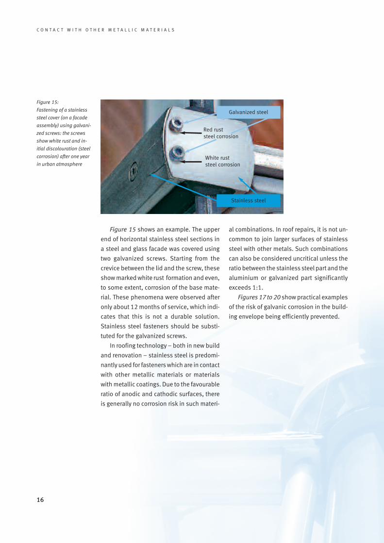
Figure 15 shows an example. The upper
end of horizontal stainless steel sections in
a steel and glass facade was covered using
two galvanized screws. Starting from the
crevice between the lid and the screw, these
show marked white rust formation and even,
to some extent, corrosion of the base mate-
rial. These phenomena were observed after
only about 12 months of service, which indi-
cates that this is not a durable solution.
Stainless steel fasteners should be substi-
tuted for the galvanized screws.
In roofing technology – both in new build
and renovation – stainless steel is predomi-
nantly used for fasteners which are in contact
with other metallic materials or materials
with metallic coatings. Due to the favourable
ratio of anodic and cathodic surfaces, there
is generally no corrosion risk in such materi-
al combinations. In roof repairs, it is not un-
common to join larger surfaces of stainless
steel with other metals. Such combinations
can also be considered uncritical unless the
ratio between the stainless steel part and the
aluminium or galvanized part significantly
exceeds 1:1.
Figures 17 to 20 show practical examples
of the risk of galvanic corrosion in the build-
ing envelope being efficiently prevented.
Stainless steel
Galvanized steel
Figure 15:
Fastening of a stainless
steel cover (on a facade
assembly) using galvani-
zed screws: the screws
show white rust and in-
itial discolouration (steel
corrosion) after one year
in urban atmosphere
Red ruststeel corrosion
White ruststeel corrosion

17
C O N T A C T W I T H O T H E R M E T A L L I C M A T E R I A L S
Figure 17:
Fastening stainless steel
outer panels to a carbon
steel structure on the
Atomium, Brussels
Figure 18:
The stainless steel outer
panel is insulated from
the inner galvanized
steel panel by suitable
joints.
Figure 20:
To prevent galvanic
corrosion, the stainless
steel cladding is fastened
to the carbon steel inner
structure in non-humid
areas.
Figure 19:
Fabricating insulated
panels using stainless
steel for the outer shell
and galvanized carbon
steel for the inner shell
18
C O N T A C T W I T H O T H E R M E T A L L I C M A T E R I A L S
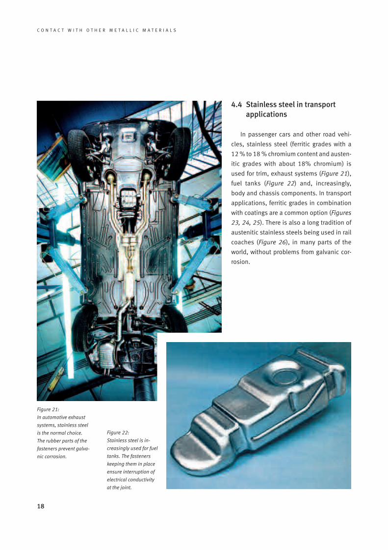
4.4 Stainless steel in transportapplications
In passenger cars and other road vehi-
cles, stainless steel (ferritic grades with a
12 % to 18 % chromium content and austen-
itic grades with about 18% chromium) is
used for trim, exhaust systems (Figure 21),
fuel tanks (Figure 22) and, increasingly,
body and chassis components. In transport
applications, ferritic grades in combination
with coatings are a common option (Figures
23, 24, 25). There is also a long tradition of
austenitic stainless steels being used in rail
coaches (Figure 26), in many parts of the
world, without problems from galvanic cor-
rosion.
Figure 21:
In automotive exhaust
systems, stainless steel
is the normal choice.
The rubber parts of the
fasteners prevent galva-
nic corrosion.
Figure 22:
Stainless steel is in-
creasingly used for fuel
tanks. The fasteners
keeping them in place
ensure interruption of
electrical conductivity
at the joint.

19
C O N T A C T W I T H O T H E R M E T A L L I C M A T E R I A L S
Figure 23:
Simple insulation techni-
ques make the tram’s
ferritic stainless steel
body compatible with the
carbon steel chassis.
Figure 26:
Rail coaches with outer
panels in austenitic
stainless steel have been
used in many parts of the
world, without galvanic
corrosion problems.
Figure 25:
Used for buses and
coaches, stainless steel
(usually a painted ferritic
grade) has proved com-
patible with a carbon
steel chassis.
Figure 24:
In this side wall of a com-
muter train, the structure
and outer panels are in
different grades of stain-
less steel. As these have
identical potentials, no
galvanic corrosion can
occur.
Here, too, it is essential to avoid crevices
between stainless steel components and
less noble materials, in which corrosive at-
tacks can occur due to dirt and humidity.
Once again, the crevices can be filled with a
suitable polymer. Another effective precau-
tion against galvanic corrosion in transport
applications is the local coating of a contact
zone on the stainless steel side, as de-
scribed above.

20
C O N T A C T W I T H O T H E R M E T A L L I C M A T E R I A L S
Question:
Is there a risk of galvanic corrosion if
stainless steel grades of different chemical
composition are joined?
Answer:
Between stainless steels of different
types (also among different corrosion-resis-
tance classes) there is generally no galvanic
corrosion, as the free corrosion potentials of
both partner metals are identical. However,
the corrosion resistance of each alloy must
be considered individually. Also the materi-
al with lower corrosion resistance must be
Frequently Asked Questions
sufficiently corrosion resistant in the condi-
tions concerned (Figure 27).
Question:
Can stainless steel be used in combina-
tion with copper or galvanized steel for the
repair of domestic plumbing systems?
Answer:
No problems are to be expected when
stainless steel is combined with copper
plumbing, as both materials have similar cor-
rosion potential in potable water. Plumbing
components made of hot-dip galvanized
steel can also be combined with stainless
steel. However, couplers of copper zinc al-
loys or red brass are recommended.
Question:
Can stainless steel rebar be joined with
carbon steel in reinforced concrete?
Answer:
Yes, for carbon steel reinforcement, such
a combination does not normally raise cor-
rosion questions, as the corrosion potentials
are identical. Such a combination can be
Figure 27:
No galvanic corrosion
will occur between diffe-
rent types of stainless
steel, even if they do not
have the same corrosion
resistance.
21
C O N T A C T W I T H O T H E R M E T A L L I C M A T E R I A L S
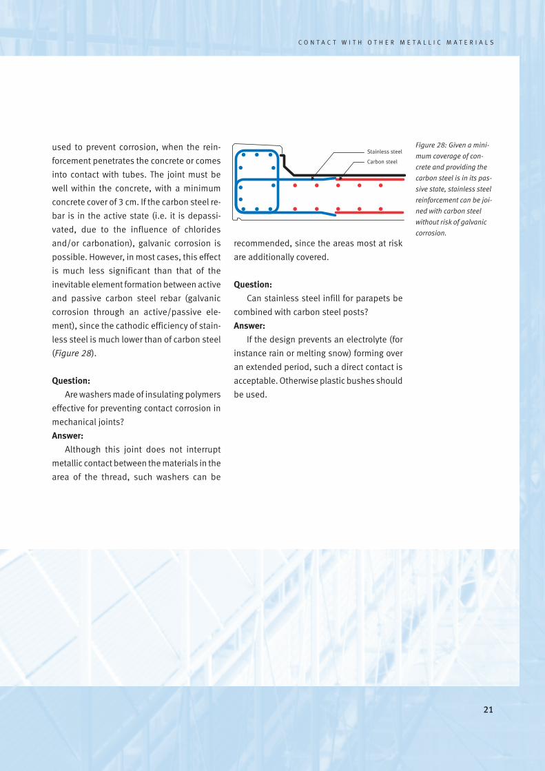
Figure 28: Given a mini-
mum coverage of con-
crete and providing the
carbon steel is in its pas-
sive state, stainless steel
reinforcement can be joi-
ned with carbon steel
without risk of galvanic
corrosion.
used to prevent corrosion, when the rein-
forcement penetrates the concrete or comes
into contact with tubes. The joint must be
well within the concrete, with a minimum
concrete cover of 3 cm. If the carbon steel re-
bar is in the active state (i.e. it is depassi-
vated, due to the influence of chlorides
and/or carbonation), galvanic corrosion is
possible. However, in most cases, this effect
is much less significant than that of the
inevitable element formation between active
and passive carbon steel rebar (galvanic
corrosion through an active/passive ele-
ment), since the cathodic efficiency of stain-
less steel is much lower than of carbon steel
(Figure 28).
Question:
Are washers made of insulating polymers
effective for preventing contact corrosion in
mechanical joints?
Answer:
Although this joint does not interrupt
metallic contact between the materials in the
area of the thread, such washers can be
recommended, since the areas most at risk
are additionally covered.
Question:
Can stainless steel infill for parapets be
combined with carbon steel posts?
Answer:
If the design prevents an electrolyte (for
instance rain or melting snow) forming over
an extended period, such a direct contact is
acceptable. Otherwise plastic bushes should
be used.
Stainless steel
Carbon steel

22
C O N T A C T W I T H O T H E R M E T A L L I C M A T E R I A L S
Figure 29:
The prevention of contact
corrosion in galvanized
steel by coating a small
area on the stainless
steel side. Results of an
48-hour salt-spray test:
without a coating, galva-
nic corrosion induces
rusting (left), while coa-
ting stainless steel in the
contact area prevents
galvanic corrosion
(right).
The obvious way to prevent galvanic cor-
rosion is to select suitably compatible mate-
rials at design stage. If the materials that
have to be used could interfere with each
other, protective measures must be taken.
Section 2 provides guidance on the nature of
these measures. Figure 3 describes the prac-
tical possibilities:
• Electrical insulation of the compo-
nents (insulators, plastic bushes or
polyamide washers)
• Positioning of the joint in an area not
exposed to humidity
• Coating a cathode or an anode and
cathode (either on large surface areas
or locally, near the joint).
It should be noted that just coating the
anode is not a suitable way to prevent gal-
vanic corrosion. Imperfection in the coating
or local damage, which are difficult to avoid
on-site, create a critical corrosion element:
any damage to the coating exposes a small
anode, which can then corrode rapidly.
5 Preventing galvanic corrosion
To reduce the cathodic effect of the stain-
less steel part, it is often sufficient to coat the
stainless steel around the joint (Figure 29).
The width of the zone to be covered depends
on the conductivity of the corrosive environ-
ment. In components exposed to normal
room atmosphere and rather thin and weak-
ly conductive electrolyte films, it is often suf-
ficient to coat an area only a few centimetres
wide along the contact line on the stainless
steel side. In salty liquid films several mil-
limetres thick, the effective cathode area be-
comes wider than 10 cm.
Stainlesssteel
Galvanized steel
Stainless steel
Galvanized steelCoating on thestainless steel

23
C O N T A C T W I T H O T H E R M E T A L L I C M A T E R I A L S
[1] DIN EN ISO 8044, Ausgabe:1999-11Korrosion von Metallen undLegierungen – Grundbegriffe und Definitionen
[2] DIN EN 12502 Teil 1 bis 5, Ausgabe:2005-03Korrosionsschutz metallischerWerkstoffe – Hinweise zurAbschätzung der Korrosionswahr-scheinlichkeit in Wasserverteilungs-und Speichersystemen
[3] H. Gräfen, ”Korrosionsschutz durch Information und Normung“Kommentar zum DIN-Taschenbuch219, Verlag Irene Kuron, Bonn (1988)S. 37
[4] H. Spähn, K. Fäßler ”Kontaktkorrosion“Werkstoffe und Korrosion 17 (1966) S. 321
[5] D. Kuron ”Aufstellung von Kontaktkorrosions-tabellen für Werkstoffkombinationenin Wässern“Werkstoffe und Korrosion 36 (1985) S. 173
[6] D. Kuron, E.-M. Horn, H. Gräfen”Praktische elektrochemischeKontaktkorrosionstabellen vonKonstruktionswerkstoffen des Chemie-Apparatebaues“Metalloberfläche 26 (1967) Nr. 2, S. 38
[7] H. Spähn, K. Fäßler ”Kontaktkorrosion im Maschinen- und Apparatebau“Der Maschinen Schaden 40 (1967) Nr. 3, S. 81
6 Literature
[8] W. Schwenk”Probleme der Kontaktkorrosion“Metalloberfläche 35 (1981) Nr. 5, S. 158
[9] K.-H. Wiedemann, B. Gerodetti, R.Dietiker, P. Gritsch”Automatische Ermittlung vonKontaktkorrosionsdaten und ihreAuswertung mittelsPolarisationsdiagrammen“Werkstoffe und Korrosion 29 (1978) S. 27
[10] E. Hargarter, H. Sass”Kontaktkorrosion zwischen verschie-denen Werkstoffen in Meerwasser“Jahrbuch der SchiffbautechnischenGesellschaft 80 (1986) S. 105
[11] R. Francis”Galvanic Corrosion: a Practical Guide for Engineers“NACE International (2001) Houston Texas 77084ISBN 1 57590 110 2
[12] GfKorr-Merkblatt 1.013”KorrosionsschutzgerechteKonstruktion”(2005)
[13] Allgemeine bauaufsichtlicheZulassung Z-30.3-6 ”Erzeugnisse, Verbindungsmittel undBauteile aus nichtrostenden Stählen“ (jeweils gültige Fassung) Sonderdruck 862 der Infor-mationsstelle Edelstahl Rostfrei

24
C O N T A C T W I T H O T H E R M E T A L L I C M A T E R I A L S

Stainless Steel in Contactwith Other Metallic Materials
Materials and Applications Series, Volume 10Diamant Building · Bd. A. Reyers 80 · 1030 Brussels· Belgium ·Tel. +32 2 706 82-67 · Fax -69 · e-mail [email protected] · www.euro-inox.org
ISBN 978-2-87997-263-3
Metal 1Anode
Metal 2Cathode
Electrolyte
e-


