20
INSTALLATION, OPERATION AND MAINTENANCE INSTRUCTIONS MANUAL www.stalkerpumps.com.au 2011 STALKER PUMPS BARESHAFT PUMP
INSTALLATION, OPERATION AND MAINTENANCE INSTRUCTIONS MANUAL
www.stalkerpumps.com.au 2011
STALKER PUMPS
BARESHAFT PUMP
INSTALLATION, OPERATION AND MAINTENANCE INSTRUCTIONS MANUAL
www.stalkerpumps.com.au 2011
FOREWORD This manual provides instructions for the installation, operation and maintenance of the Stalker Pumps Bareshaft Pump. This manual must be read and understood before installation and maintenance. The design, materials, and workmanship incorporated in the construction of Stalker Pumps make them capable of giving long, trouble-free service. The life and satisfactory service of any mechanical unit, however, is enhanced and extended by correct application, proper installation, periodic inspection, condition monitoring and careful maintenance. Stalker Pumps shall not be liable for physical injury, damage or delays caused by a failure to observe the instructions for Installation, Operation, and maintenance contained in this manual. Warranty is valid only when genuine Stalker Pumps parts are used. Use of the pump/unit on a service other than stated in the product data sheet will nullify the warranty, unless written approval is obtained in advance from Stalker Pumps.
THIS MANUAL EXPLAINS
Proper installation Start-up procedures Operation procedures Routine maintenance Troubleshooting Ordering spare parts
INSTALLATION, OPERATION AND MAINTENANCE INSTRUCTIONS MANUAL
www.stalkerpumps.com.au Page 1 of 18 2012
TABLE OF CONTENTS
1 INTRODUCTION AND SAFETY 3 1.1 General 3 1.2 Disclaimer 3 1.3 Duty Conditions 4 1.4 Safety 4 1.4.1 Summary of Safety Markings 4 1.4.2 Personnel Qualification and Training 5 1.4.3 Safety Action 5 1.4.4 Preventing Leakage 6 1.5 Nameplate and Safety Labels 6 2 TRANSPORT AND STORAGE 7 2.1 Consignment Receipt and Unpacking 7 2.2 Handling 7 2.2.1 General Instructions Concerning Handling 7 2.3 Lifting 8 2.4 Storage 8 3 INSTALLATION 9 3.1 Location 9 3.2 Foundation 9 3.3 Suction Piping 9 3.4 Discharge Piping 10 3.5 Electrical Connections 10 3.6 Bolting Procedure 10 4 COMMISSIONING, START-UP, OPERATION AND SHUTDOWN 12 4.1 Pre-commissioning 12 4.2 Commissioning 12 4.3 Start Up 13 5 MAINTENANCE 14 5.1 General 14 5.2 Assembly Procedure 14 5.3 Disassembly Procedure 14 5.4 Maintenance Schedule 14 5.4.1 Routine Inspection 14 5.5 Spare Parts 15 5.5.1 Ordering of Spares 15 5.5.2 Storage of Spares 16

INSTALLATION, OPERATION AND MAINTENANCE INSTRUCTIONS MANUAL
www.stalkerpumps.com.au Page 2 of 18 2012
6 GENERAL TROUBLESHOOTING 17
INSTALLATION, OPERATION AND MAINTENANCE INSTRUCTIONS MANUAL
www.stalkerpumps.com.au Page 3 of 18 2012
1 INTRODUCTION AND SAFETY 1.1 General These instructions must always be kept close to the product's operating location or directly with the product. These instructions must be read prior to installing, operating, using and maintaining the equipment in any region within Australia or worldwide. The equipment must not be put into service until all the conditions relating to safety noted in the instructions, have been met. Failure to follow and apply the present user instructions is considered to be misuse. Personal injury, product damage, delay or failures caused by misuse are not covered by the Stalker Pumps warranty. Stalker’s products are designed, developed and manufactured with state-of-the-art technologies in modern facilities. The unit is produced with great care and commitment to continuous quality control, utilizing sophisticated quality techniques, and safety requirements. Stalker Pumps is committed to continuous quality improvement and being at service for any further information about the product in its installation and operation or about its support products, repair and diagnostic services. These instructions are intended to facilitate familiarization with the product and its permitted use. Operating the product in compliance with these instructions is important to help ensure reliability in service and avoid risks. The instructions may not take into account local regulations; ensure such regulations are observed by all, including those installing the product. Always coordinate repair activity with operations personnel, and follow all plant safety requirements and applicable safety and health laws and regulations. 1.2 Disclaimer Considerable effort has been made to ensure that this manual is free of inaccuracies and omissions. However, even though the manual contains up to date data at time of going to press, due to constant improvements some of the data contained herein may not exactly reflect the current model of the particular product described in this manual. Stalker Pumps reserves the right to change the construction and design of the products at any time without being obliged to change previous models accordingly. Stalker Pumps manufactures products to comply with International Quality Management System Standards as certified and audited by external Quality Assurance organizations. Genuine parts and accessories have been designed, tested and incorporated into the products to help ensure their continued product quality and performance in use. As Stalker Pumps cannot test parts and accessories sourced from other vendors the incorrect incorporation of such parts and accessories may adversely affect the performance and safety features of the products. The failure to properly select, install or use authorized Stalker Pumps parts and accessories is considered to be misuse. Damage or failure caused by misuse is not covered by the Stalker Pumps warranty. In addition, any modification of Stalker Pumps products or removal of original components may impair the safety of these products in their use.
INSTALLATION, OPERATION AND MAINTENANCE INSTRUCTIONS MANUAL
www.stalkerpumps.com.au Page 4 of 18 2012
1.3 Duty Conditions This product has been designed/selected/fabricated to meet the specifications of your purchase order. The product must not be operated beyond the parameters specified for the application. If there is any doubt as to the suitability of the product for the application intended, contact Stalker Pumps for advice, quoting the serial number. If the conditions of service on your purchase order are going to be changed (for example liquid pumped, temperature or duty) it is requested that the user seeks the written agreement of Stalker Pumps before start up. 1.4 Safety Stalker Pumps recommends users of our equipment follow the latest Industrial Safety Standards.
Attention: Servicing energized industrial equipment can be hazardous. Severe injury or death can result from electrical shock, burn, or unintended actuation of controlled equipment. Recommended practice is to disconnect and lockout industrial equipment from power sources, and release stored energy, if present.
Locking and Interlocking Devices: These devices should be checked for proper working condition and capability of performing their intended functions. Make replacements only with the original manufacturer’s renewal parts. Adjust or repair in accordance with the manufacturer’s instructions.
Periodic Inspection: Industrial equipment should be inspected periodically. Inspection intervals should be based on environmental and operating conditions and adjusted as indicated by experience. At a minimum, an initial inspection within 3 to 4 months after installation is recommended. Inspection of the electrical control systems should meet the recommendations as specified in the Australian Electrical and Electronic Manufacturers Association (AEEMA).
Replacement Equipment: Use only replacement parts and devices recommended by the manufacturer to maintain the integrity of the equipment. Make sure the parts are properly matched to the equipment series, model, serial number, and revision level of the equipment.
1.4.1 Summary of Safety Markings Warnings and cautions are provided in this manual to help avoid serious injury and/or possible damage to equipment:
DANGER: marked with a stop sign. Immediate hazards which WILL result in severe personal injury or death.
WARNING: marked with a warning triangle. Hazards or unsafe practices which COULD result in
severe personal injury or death.
CAUTION: marked with a warning triangle. Hazards or unsafe practices which COULD result in minor personal injury or product or property damage.

INSTALLATION, OPERATION AND MAINTENANCE INSTRUCTIONS MANUAL
www.stalkerpumps.com.au Page 5 of 18 2012
1.4.2 Personnel Qualification and Training All personnel involved in the operation, installation, inspection and maintenance of the unit must be qualified to carry out the work involved. If the personnel in question do not already possess the necessary knowledge and skill, It is the CUSTOMER’S responsibility to provide appropriate training and instruction. Always coordinate repair activity with operations and health and safety personnel, and follow all plant safety requirements and applicable safety and health laws and regulations. 1.4.3 Safety Action This is a summary of conditions and actions to prevent injury to personnel and damage to the environment and to equipment
Never perform maintenance work when the unit is connected to power.
Guards must not be removed while the pump is in operation.
Drain the pump and isolate pipework before dismantling the pump.
Handling components Many parts have sharp corners and the wearing of appropriate safety gloves and equipment is required when handling these components. To lift heavy pieces above 25 kg (55 lb) use a crane appropriate for the mass and in accordance with current local regulations.
Never apply heat to remove impeller Trapped lubricant or vapour could cause an explosion.
Hot (and cold) parts If hot or freezing components or auxiliary heating supplies can present a danger to operators and persons entering the immediate area action must be taken to avoid accidental contact. If complete protection is not possible, the machine access must be limited to maintenance staff only, with clear visual warnings and indicators to those entering the immediate area. Note: Bearing housings must not be insulated and drive motors and bearings may be hot.
Ensure correct lubrication (See section 5, Maintenance)
Start the pump with outlet valve partly opened. (Unless otherwise instructed at a specific point in the User Instructions.) This is recommended to minimize the risk of overloading and damaging the pump motor at full or zero flow. Pumps may be started with the valve further open only on installations where this situation cannot occur. The pump outlet control valve may need to be adjusted to comply with the duty following the run-up process. (See section 5, Commissioning start-up, operation and shutdown.)
INSTALLATION, OPERATION AND MAINTENANCE INSTRUCTIONS MANUAL
www.stalkerpumps.com.au Page 6 of 18 2012
Never run the pump dry
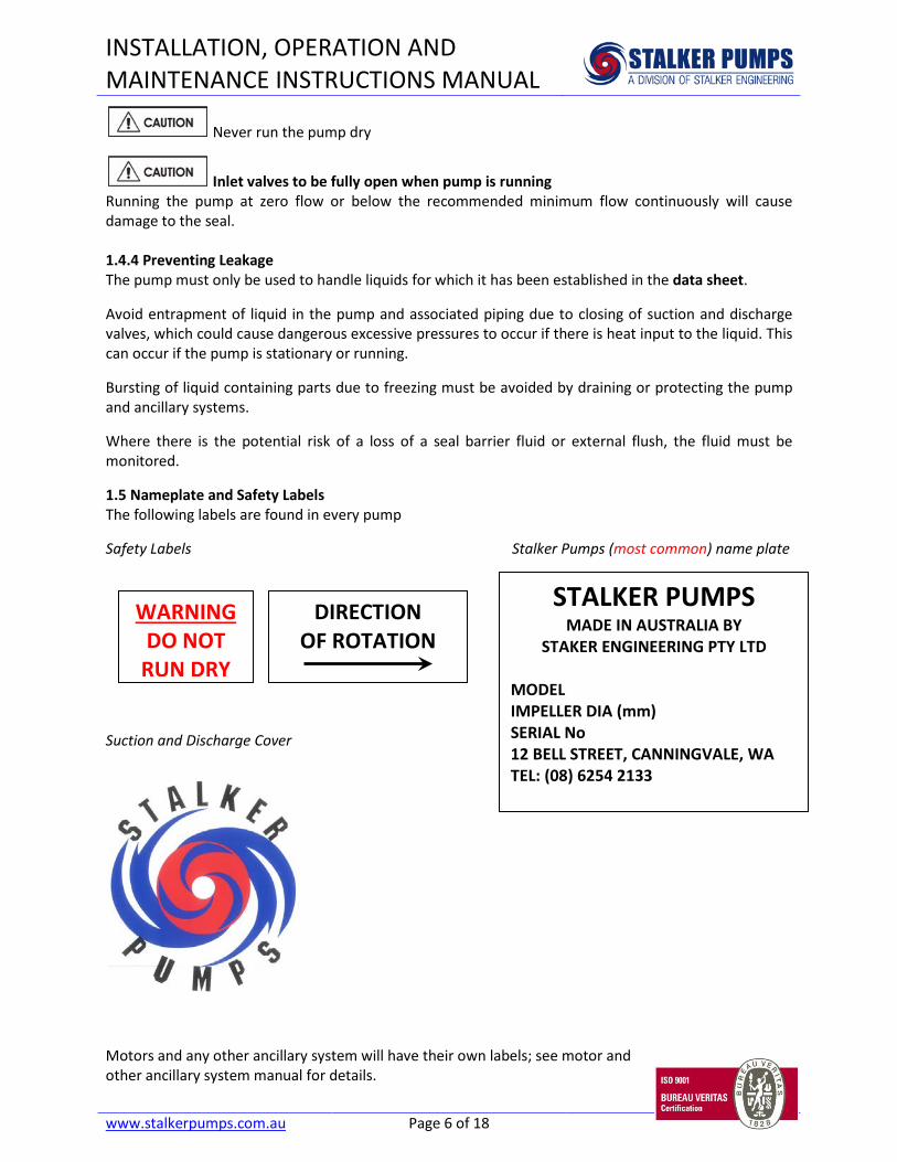
Inlet valves to be fully open when pump is running Running the pump at zero flow or below the recommended minimum flow continuously will cause damage to the seal. 1.4.4 Preventing Leakage The pump must only be used to handle liquids for which it has been established in the data sheet. Avoid entrapment of liquid in the pump and associated piping due to closing of suction and discharge valves, which could cause dangerous excessive pressures to occur if there is heat input to the liquid. This can occur if the pump is stationary or running. Bursting of liquid containing parts due to freezing must be avoided by draining or protecting the pump and ancillary systems. Where there is the potential risk of a loss of a seal barrier fluid or external flush, the fluid must be monitored. 1.5 Nameplate and Safety Labels The following labels are found in every pump Safety Labels Stalker Pumps (most common) name plate Suction and Discharge Cover
Motors and any other ancillary system will have their own labels; see motor and other ancillary system manual for details.
WARNING DO NOT
RUN DRY
DIRECTION OF ROTATION
STALKER PUMPS MADE IN AUSTRALIA BY
STAKER ENGINEERING PTY LTD MODEL IMPELLER DIA (mm) SERIAL No 12 BELL STREET, CANNINGVALE, WA TEL: (08) 6254 2133

INSTALLATION, OPERATION AND MAINTENANCE INSTRUCTIONS MANUAL
www.stalkerpumps.com.au Page 7 of 18 2012
2 TRANSPORT AND STORAGE 2.1 Consignment Receipt and Unpacking Immediately after receipt of unit, it must be checked with the delivery and shipping documents for its completeness and to ensure that there has been no damage during transportation. Damage or loss should be reported immediately to the delivery carrier while present. Following the immediate notification of the lost or damaged parts, a detailed description of the loss or damage, and a cash value should be claimed against the carrier. Stalker's responsibility terminates F.O.B. point of manufacture unless otherwise specified on the Contract by Stalker Pumps and the customer.
The unit has been tested and inspected prior to shipment. When leaving Stalker premises, was well crated for normal transportation procedures. Stalker Pumps cannot, however, guarantee safe arrival.
Any shortage and or damage shall be reported immediately to Stalker Pumps and received in writing within a month. Claims coming in afterwards cannot be accepted. Check any crate, box and wrappings for any accessories or spare parts that may be packed separately with the equipment or attached to side walls of the box or equipment. Each product has a unique serial number. Check that this number corresponds with that; advised and always quote this number in correspondence as well as when ordering spare parts or further accessories. 2.2 Handling Boxes, crates, pallets or cartons may be unloaded using cranes, fork-lift vehicles or slings dependent on their size and construction. 2.2.1 General Instructions Concerning Handling To lift heavy pieces above 25 kg (55 lb), use a winch adapted to the mass and in accordance with the current local regulations. To lift machines or pieces with one or several suspension rings, only use hooks and chains in compliance with the local regulations concerning safety. Never put cables, chains or ropes directly on or in the suspension rings. Cables, chains or lifting ropes must never present excessive bending. Never bend the lifting hooks, suspension rings, chains, etc., which should only be made to endure stresses within calculated limits. Remember that the capacity of a lifting device decreases when the direction of the lifting force direction makes an angle with the device axis. To increase the safety and the efficiency of the lifting device, all the lifting elements must be as perpendicular as possible. If necessary a lifting beam can be placed between the winch and the load. When heavy pieces are lifted up, never stay or work under the load or in the area, which could be in the path of the load if it were to swing or fall away. Never leave a load hanging from a winch. The acceleration or the slowing-down of lifting equipment must stay in the safety limits for the staff.

INSTALLATION, OPERATION AND MAINTENANCE INSTRUCTIONS MANUAL
www.stalkerpumps.com.au Page 8 of 18 2012
A winch must be positioned in such a way that the load will be raised perpendicularly. Where possible, necessary precautions must be taken to avoid the swing of the load, using for example two winches making approximately the same angle, below 30°, with the vertical. 2.3 Lifting It is strongly recommended to attempt lifting with appropriate tools and equipments only. It is strongly recommended to employ experts or approved weight handling methods to avoid injury or loss of life. A crane must be used for all pump/unit sets in excess of 25 kg (55 lb). Fully trained personnel must carry out lifting, in accordance with local regulations. 2.4 Storage If the pump is not to be used immediately: The pump shaft must be turned by hand (if pump only) twice a week or turn unit on (if pump and motor) once a week in order to prevent the impeller, the mechanical seal and the bearing from becoming seized up. Store the unit in a clean, dry location away from vibration. Leave piping connection covers in place to keep dirt and other foreign material out of pump casing.
If equipment is damaged or lost in transit, file a claim at once with the delivering carrier. The carrier has signed the Bill of Lading acknowledging that the shipment has been received from Stalker Pumps in good condition. Stalker Pumps is not responsible for the collection of claims
or replacement of materials due to transit shortages or damages.

INSTALLATION, OPERATION AND MAINTENANCE INSTRUCTIONS MANUAL
www.stalkerpumps.com.au Page 9 of 18 2012
3 INSTALLATION Equipment operated in hazardous locations must comply with the relevant explosion protection regulations. Upon receipt of the pump, ensure that it has not been damaged in transit and that no parts are missing. Take care in unloading and handling of equipment to avoid damage. 3.1 Location The pump/unit should be placed so as to allow room for access, ventilation, maintenance and inspection with ample headroom for lifting and should be as close as practicable to the supply of liquid to be pumped. 3.2 Foundation The foundation must be of sufficient size and the rigidity so as to prevent movement when the pump unit is anchored down and to absorb vibration when the pump is running. It must also be even to prevent distortion of the base plate when the holding down bolts are tightened. A well laid concrete slab is the most effective way of ensuring a sound foundation. The coupling face (if direct coupled), suction and discharge flanges of the pump should also be checked for horizontal or vertical position by use of a level. If the pump is to be installed into existing piping, it is recommended to connect the pump to the pipe flanges. This enables the pump unit to be moved slightly to suit the existing pipework. Flange connections and holding down bolts are then lightly tightened. NOTE: The foundation bolts should preferably be installed in pipe sleeve type holders. When the pump is set up and level, the grout should be thoroughly worked under the baseplate and allowed to set for about 48 hours. Once the grout has set, the holding down bolts should be tightened evenly. The shaft should be turned by hand to ensure it is running freely. NOTE: DO NOT OVERTIGHTEN HOLDING DOWN BOLTS OR BASEPLATE MAY DISTORT. 3.3 Suction Piping A common cause of the unsatisfactory operation of a centrifugal pump is the improper installation of the suction piping. Particular care should be taken to ensure that: 1. All joints and pipes are absolutely air tight. 2. Suitable piping is used. 3. The nominal size of the suction piping (as a general rule) must not be less than the size of the suction opening of the pump. NOTE: Larger diameter piping can be used to advantage, particularly when a long suction pipe is necessary.
INSTALLATION, OPERATION AND MAINTENANCE INSTRUCTIONS MANUAL
www.stalkerpumps.com.au Page 10 of 18 2012
4. Except where the pump is below the level of supply, ensure that: a) No part of the suction pipe is above the level of the suction opening on the pump. b) A continual fall is maintained between the pump and liquid source to prevent air pockets forming. In order to avoid formation of air pockets an eccentric taper pipe should be used. (This applies when suction piping diameter is greater than pump suction opening). c) ) Ensure the area in the foot valve strainer is larger than or equal to the suction pipe diameter and that it seals properly. This should be arranged in the vertical position with adequate liquid submergence to ensure air is not drawn through the suction piping when the pump is operating.
NOTE: Please consult Stalker Pumps Technical Consultants or distributors if unsure as to the correct submergence depth of your particular pump. 3.4 Discharge Piping A pipe of suitable size to carry the normal discharge of the pump, without excessive frictional resistance, should be selected. As a general rule, the diameter of the delivery pipe should be at least one size larger than the pump discharge size. This practice helps to minimise hydraulic losses due to pipe friction. In cases where the delivery pipe has high points, air locks are likely to occur. In such cases air relief valves should be fitted to allow the escape of accumulated air which may affect the capacity of the pump. A gate valve or butterfly valve fitted in the discharge pipe close to the pump will enable the capacity to be controlled and also enable the pump to be isolated for maintenance purposes. NOTE: ON NO ACCOUNT REGULATE FLOW OF PUMP BY USE OF A SUCTION VALVE. (IF FITTED) 3.5 Electrical Connections
Electrical connections must be made by a qualified Electrician in accordance with relevant local national and international regulations.
The motor must be wired up in accordance with the motor manufacturer's instructions (normally supplied within the terminal box) including any temperature, earth leakage, current and other protective devices as appropriate. The identification nameplate should be checked to ensure the power supply is appropriate.
A device to provide emergency stopping must be fitted. If not supplied pre-wired to the pump unit, the controller/starter electrical details will also be supplied within the controller/starter. For electrical details on pump sets with controllers see the separate wiring diagram.
3.6 Bolting Procedure General - This procedure is equally applicable to galvanised and ungalvanised bolts. - After assembly, all bolts and nuts in the joint shall be tightened evenly to a snug tight condition. - Bill of materials list indicates the grade and diameter of all bolts, nuts and washers required for the assembly. Figure 1 shows where bolts for major components are allocated. - All oil, dirt, loose scale, loose rust, burrs, fins and any other defects on the contact surfaces shall be removed prior to fitting the parts together.

INSTALLATION, OPERATION AND MAINTENANCE INSTRUCTIONS MANUAL
www.stalkerpumps.com.au Page 11 of 18 2012
- Prior to using, conduct a visual inspection of all fasteners to verify that they are of the correct type, size, and length for the intended use, and they are not damage, soiled, corroded or stripped of their lubricant.

INSTALLATION, OPERATION AND MAINTENANCE INSTRUCTIONS MANUAL
www.stalkerpumps.com.au Page 12 of 18 2012
4 COMMISSIONING, START-UP AND OPERATION 4.1 Pre-commissioning and Start Up and Commissioning
Centrifugal Pump Commissioning Procedure Pre commissioning
- Starting or operating pumps with the wrong direction of rotation can be harmful to the pumps. Ensure that the pump rotation is the same as the arrow on the pump casing.
- If maintenance work has been carried out to the site's electricity supply, the direction of rotation should be re-checked as above in case the supply phasing has been altered. - Guarding is supplied fitted to the pump set. If this has been removed or disturbed ensure that all the protective guards around the exposed parts of the shaft are securely fixed. 4.2 Commissioning Commissioning - Pump bearings must be filled with the recommended lubricant to avoid running dry and to guarantee acceptable performance of the pump. - Check all vent connections for complete filling of the pump. - Check the readiness of all auxiliary systems (seal system, lubrication system) for start up. - All pipe work must be connected correctly and must be absolutely tight. Check the tightness of all connections of the auxiliary pipe work. The suction valve must be open; the discharge valve shall be closed or partially open as required. - Turn the pump shaft rotates freely by hand. The rotor must turn uniformly and noiselessly. Some resistance may be felt due to the friction in the bearings and seals. - Check the readiness of the driver for start up. Refer to driver user instructions before energizing the motor.
INSTALLATION, OPERATION AND MAINTENANCE INSTRUCTIONS MANUAL
www.stalkerpumps.com.au Page 13 of 18 2012
4.3 Start Up
Start up
- Do not operate the pump without first priming or severe damage or failure of the mechanical seal will occur.
1. Close discharge gate valve (Note: Do not run the pump for more than two minutes with the discharge gate valve fully closed.) 2. Prime the pump casing and suction pipe work to remove all air either by manually filling or using a diaphragm pump. 3. Re-check pump drive shaft rotation. 4. Start pump unit. 5. When pump has reached operating speed, slowly open the discharge gate valve until the correct liquid flow is delivered and discharge pipe has filled.
IMPORTANT: If no liquid is being discharged – shut down immediately.
6. If the pump unit is operating correctly then check for abnormal noise, operating temperature and mechanical seal area for leaks. 7. Shut pump unit down. 8. Re-check coupling alignment.
INSTALLATION, OPERATION AND MAINTENANCE INSTRUCTIONS MANUAL
www.stalkerpumps.com.au Page 14 of 18 2012
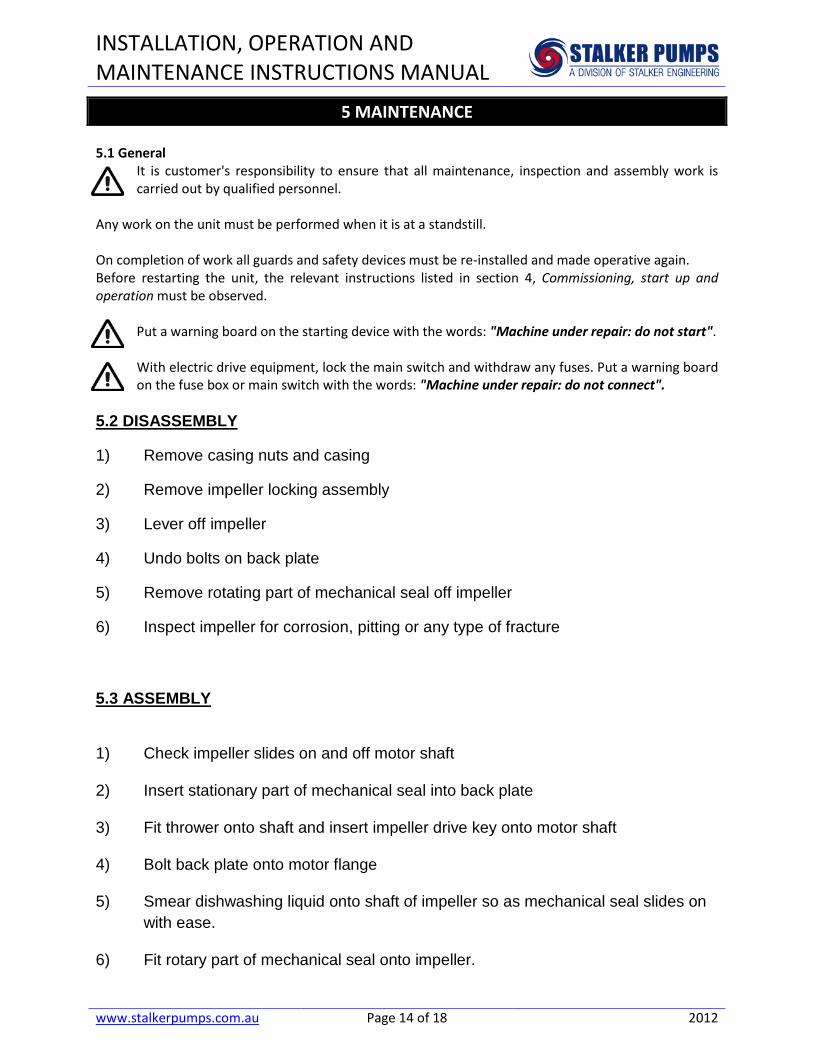
5 MAINTENANCE 5.1 General
It is customer's responsibility to ensure that all maintenance, inspection and assembly work is carried out by qualified personnel.
Any work on the unit must be performed when it is at a standstill. On completion of work all guards and safety devices must be re-installed and made operative again. Before restarting the unit, the relevant instructions listed in section 4, Commissioning, start up and operation must be observed.
Put a warning board on the starting device with the words: "Machine under repair: do not start". With electric drive equipment, lock the main switch and withdraw any fuses. Put a warning board on the fuse box or main switch with the words: "Machine under repair: do not connect".
5.2 DISASSEMBLY
1) Remove casing nuts and casing
2) Remove impeller locking assembly
3) Lever off impeller
4) Undo bolts on back plate
5) Remove rotating part of mechanical seal off impeller
6) Inspect impeller for corrosion, pitting or any type of fracture
5.3 ASSEMBLY
1) Check impeller slides on and off motor shaft
2) Insert stationary part of mechanical seal into back plate
3) Fit thrower onto shaft and insert impeller drive key onto motor shaft
4) Bolt back plate onto motor flange
5) Smear dishwashing liquid onto shaft of impeller so as mechanical seal slides on with ease.
6) Fit rotary part of mechanical seal onto impeller.

INSTALLATION, OPERATION AND MAINTENANCE INSTRUCTIONS MANUAL
www.stalkerpumps.com.au Page 15 of 18 2012
IMPORTANT: DO NOT PUSH ROTARY DOWN ONTO SPRING, ALLOW ROTARY TO SIT DOWN ON SPRING.
7) Slide impeller onto motor shaft push down and screw locking assembly back into
shaft and tighten.
8) Bolt casing onto back plate.
5.4 Maintenance Schedule A maintenance plan should include the following: - Check for any leakage from gaskets and seals. The correct functioning of the shaft seal must be
checked regularly. - Check motor bearing lubricant at intervals as described in the motor instructions. - Check that the duty condition is in the safe operating range for the pump. - Check vibration, noise level and surface temperature at the bearings to confirm satisfactory
operation. - Check dirt and dust is removed from areas around close clearances and motors. This allows the
identification of leakage. To provide guidance on maintenance of different components, a service chart has been attached to this manual. See section 9 Annex. 5.4.1 Routine Inspection The following checks should be made and the appropriate action taken to remedy any deviations: - Check operating behavior. Ensure noise, vibration and bearing temperatures are normal. - Check that there is no abnormal fluid or lubricant leaks. - Check any auxiliary supplies e.g. heating/cooling, if fitted, are functioning correctly. Refer to the manuals of any associated equipment for routine checks needed.

INSTALLATION, OPERATION AND MAINTENANCE INSTRUCTIONS MANUAL
www.stalkerpumps.com.au Page 16 of 18 2012
5.5 Spare Parts
5.5.1 Ordering of Spares Stalker Pumps keeps records of all pumps that have been supplied. When ordering spares the following information should be quoted:
1) Pump serial number. 2) Pump size. 3) Part name 4) Part number 5) Number of parts required.
The pump size and serial number are shown on the pump nameplate.
To ensure continued satisfactory operation, replacement parts to the original design specification should be obtained from Stalker Pumps or who supplied the pump – if different
from the manufacturer. Any change to the original design specification (modification or use of a non-standard part) will invalidate the pump’s safety certification and therefore its guarantee. 5.5.2 Storage of Spares Spares should be stored in a clean dry area away from vibration. Inspection and re-treatment of metallic surfaces (if necessary) with preservative is recommended every 6 months

INSTALLATION, OPERATION AND MAINTENANCE INSTRUCTIONS MANUAL
www.stalkerpumps.com.au Page 17 of 18 2012
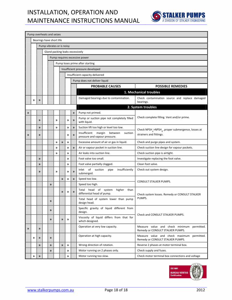
6 GENERAL TROUBLESHOOTING Between regular maintenance inspections, be alert for signs of motor or pump trouble. Common symptoms are listed below.
Pump overheats and seizes Bearings have short life
Pump vibrates or is noisy Gland packing leaks excessively
Pump requires excessive power Pump loses prime after starting
Insufficient pressure developed Insufficient capacity delivered
Pump does not deliver liquid
PROBABLE CAUSES POSSIBLE REMEDIES 1. Mechanical troubles
» » » » » Misalignment due to pipe strain. Check the flange connections and eliminate strains
using elastic couplings or a method permitted. » Improperly designed foundation. Check setting of levelling or base plate: tighten,
adjust, grout base as required.
» » » » Shaft bent. Check shaft runouts are within acceptable values.
CONSULT STALKER PUMPS.
» » »
» Rotating part rubbing on stationary part
internally. Check and CONSULT STALKER PUMPS, if necessary.
» » » » Bearings worn Replace bearings. » » » Wearing ring surfaces worn. Replace worn wear ring/surfaces.
»
» » Impeller damaged or eroded. Replace or CONSULT STALKER PUMPS for
improved material selection. » Leakage under sleeve due to joint failure. Replace joint and check for damage.
» Shaft sleeve worn or scored or running off
centre. Check and renew defective parts.
» » Gland Packing improperly installed. Check and fix.
» » » » Shaft running off centre because of worn
bearings. Check misalignment and correct if necessary. If alignment satisfactory check bearings for excessive wear.
» » » » Impeller out of balance resulting in vibration.
Check and CONSULT STALKER PUMPS. » » » Abrasive solids in liquid pumped.
» »
Internal misalignment of parts preventing seal ring and seat from mating properly.
» »
Internal misalignment due to improper repairs causing impeller to rub.
Check method of assembly, possible damage or state of cleanliness during assembly. Remedy or CONSULT STALKER PUMPS, if necessary.
» » » Excessive thrust caused by a mechanical
failure inside the pump. Check wear condition of impeller, its clearances and liquid passages.
» » Excessive grease in ball bearings. Check method of regreasing.
» » Lack of lubrication for bearings. Check hours run since last change of lubricant, the schedule and its basis.
» »
Improper installation of bearings (damage during assembly, incorrect assembly, wrong type of bearing etc).
Check method of assembly, possible damage or state of cleanliness during assembly and type of bearing used. Remedy or CONSULT STALKER PUMPS, if necessary.
INSTALLATION, OPERATION AND MAINTENANCE INSTRUCTIONS MANUAL
www.stalkerpumps.com.au Page 18 of 18 2012
Pump overheats and seizes
Bearings have short life
Pump vibrates or is noisy
Gland packing leaks excessively
Pump requires excessive power
Pump loses prime after starting
Insufficient pressure developed
Insufficient capacity delivered
Pump does not deliver liquid
PROBABLE CAUSES POSSIBLE REMEDIES 1. Mechanical troubles
» » Damaged bearings due to contamination. Check contamination source and replace damaged bearings.
2. System troubles » » Pump not primed.
Check complete filling. Vent and/or prime. » » » » Pump or suction pipe not completely filled with liquid.
» » » » Suction lift too high or level too low. Check NPSH
A>NPSH
R, proper submergence, losses at
strainers and fittings. » » » » Insufficient margin between suction pressure and vapour pressure.
» » » Excessive amount of air or gas in liquid. Check and purge pipes and system.
» » » Air or vapour pocket in suction line. Check suction line design for vapour pockets.
» » Air leaks into suction line. Check suction pipe is airtight.
» » Foot valve too small. Investigate replacing the foot valve.
» » Foot valve partially clogged. Clean foot valve.
» » » » Inlet of suction pipe insufficiently submerged.
Check out system design.
» » » Speed too low. CONSULT STALKER PUMPS.
» Speed too high.
» » » Total head of system higher than differential head of pump. Check system losses. Remedy or CONSULT STALKER
PUMPS. » Total head of system lower than pump design head.
» Specific gravity of liquid different from design.
Check and CONSULT STALKER PUMPS. » » » Viscosity of liquid differs from that for
which designed.
» » Operation at very low capacity. Measure value and check minimum permitted. Remedy or CONSULT STALKER PUMPS.
» » » Operation at high capacity. Measure value and check maximum permitted. Remedy or CONSULT STALKER PUMPS.
» » » » Wrong direction of rotation. Reverse 2 phases at motor terminal box.
» » Motor running on 2 phases only. Check supply and fuses.
» » » Motor running too slow. Check motor terminal box connections and voltage


