12
Standard Language Protocols for Photovoltaics and Storage Grid Integration Developing a Common Method for Communicating with Inverter-Based Systems May 2010 An EPRI White Paper
Standard Language Protocols for Photovoltaics and Storage Grid Integration Developing a Common Method for Communicating with Inverter-Based Systems May 2010
An EPRI White Paper
Standard Language Protocols for PV & Storage Grid Integration 2 May 2010
An EPRI White Paper
Standard Language Protocols for PV and Storage Grid Integration
U.S. federal policy is likely to spur still greater DG deployment. For example, Title 13 of the Energy Independence and Security Act of 2007 established a policy foundation for modernizing the electrical grid in a manner that provides for the “deployment and integra-tion of distributed resources and generation, including renewable resources.” And in May 2009, the Department of Energy reinforced Title 13 by announcing funding for projects to overcome barriers to the high grid penetration of solar PV resources.
Executive SummaryContinued improvement in the cost and efficiency of photovoltaic (PV) technology hints at a future in which utilities will need to ac-commodate high levels of variable distributed generation (DG) on their transmission and distribution systems. The communication-connectedness of these diverse, often small-scale devices will be an essential factor in enabling their widespread integration. In fact, the development of a common language for communicating with distributed inverter-based systems, such as solar photovoltaics (PV) and energy storage, has the potential to vastly improve the industry’s monitoring and management capabilities and more competently exploit DG’s aggregate benefits.
Current industry practices for integrating smart, communicating inverters into utility systems are, however, scarce and largely propri-etary. As a result, EPRI, along with the U.S. Department of Energy, Sandia National Laboratories, and the Solar Electric Power Associa-tion launched a collaborative research project in mid-2009 to begin a consensus-based process of identifying and standardizing a set of grid-friendly inverter/charger capabilities. The project vision included the identification of standards-based communication protocols to manage the functions. This white paper reports on the collaborative’s latest findings and recommendations, and is intended to solicit public and industry feedback to help progress the research effort.
The outcome of the collaborative’s research effort are potentially far-reaching given policy, technology, and economic factors driving increasing development of grid-tied distributed generation. Healthy government incentives such as the Investment Tax Credit (ITC), increasing conversion efficiencies, and falling production costs are helping to drive utility interest in solar PV generation. The potential emergence of a federal carbon emission reduction policy and state mandates, such as Renewable Portfolio Standards (RPS) that create specific requirements for PV, are also spurring the growth of the PV industry.
Meanwhile, storage technologies are also garnering increasing atten-tion. As one example, the nascent electric vehicle industry, which represents a large potential market for high capacity batteries, is driving investment in novel technology concepts. And stationary distributed storage systems are receiving greater attention as they begin to demonstrate the progressive ability to satisfy a range of ap-plications including frequency regulation, emergency backup power, load shifting, peak reduction, var support, harmonics management, and renewable integration.
Table of Contents
Executive Summary ..................................................... 2Background: The PV/Storage Communication Project ..... 3Potential of Communication-Connected PV and Storage Devices ....................................................... 3Architectural and Communication Considerations ............ 4Common Smart Inverter Functions ................................. 5Next Steps ................................................................. 10
This white paper was prepared by Brian Seal and Mark McGranaghan of Electric Power Research Institute.
Large deployments of distributed generators will at some point require monitoring and management by operators of the electric grid. Solar photovoltaic systems will likely be the first to challenge operators at the utility distribution level and not far behind will be plug-in electric vehicles and bat-tery systems. These distributed resources, connected via an electronic power converter (inverter), can, in aggregate, offer new opportunities for faster power control and compensation of local voltage variations. Communication will enhance grid benefit by enabling the collab oration of many small resources with the larger public power supply. Unfortunately, captur-ing these benefits today is impeded by the lack of common functions and a common language to manage inverter-based systems. The upshot: utilities will be better able to support higher grid penetration levels and to derive greater value from distributed assets such as grid-tied photovoltaics and energy storage. This paper describes efforts currently under-way to identify the basic inverter/charger capabilities and develop a standardized communication protocol to enable distributed grid support.
Standard Language Protocols for PV & Storage Grid Integration 3 May 2010
An EPRI White Paper
Standard Language Protocols for PV and Storage Grid Integration
Though currently a tiny portion of total U.S. generation, the anticipated growth in small-scale, distributed generation will likely demand that utilities optimize their management and performance, in part, through proper controls and communication systems. If done correctly, utilities will be better positioned to exploit new and enhanced revenue streams—such as improved system efficiency via peak reduction and assistance with Var management—derived via distributed energy resources (DER) like solar PV and storage. It will also be able to more competently handle inherent high penetration challenges such as ramp rate, intermittency, and distribution system voltage disturbances.
Background: The PV/Storage Communication Project In 2009, EPRI’s Photovoltaic & Storage Integration Program (P174) began a series of studies related to the high penetration of distributed energy resources (DER). One research area in this program specifically focuses on the communication aspects of DER integration, and in mid 2009, led to the launch of a broad industry collaborative to identify a common means by which smart, com-municating inverters may be integrated into utility systems. The Department of Energy, Sandia National Laboratories, and the Solar Electric Power Association, all agencies that have historically been involved in this area of study, partnered with EPRI to drive this work forward. The research effort has since engaged over 350 indi-viduals representing inverter providers, PV and storage manufactur-ers, utilities, and research organizations. (Additional participants are welcome and are encouraged to contact EPRI’s Brian Seal at [email protected] to signal their interest.)
The central goal of the PV/storage communication project is to identify a core set of potential inverter/charger capabilities that, if implemented and made available to distribution management systems, may enable higher penetration levels and enhance the value of grid-tied PV and storage devices. By working closely with the community of inverter manufacturers, the project hopes to allow for innovation and evolution of devices while at the same time making it possible to standardize communication messages for those func-tions that are common across many products.
Formally launched at a mid-2009 workshop held in Albuquerque, New Mexico during the DOE’s SEGIS-ES conference, the project initially compiled a master-list of potential uses for communication-connected PV and storage systems. The large range of use cases was
then down-selected into seven core functions deemed by project stakeholders to be of highest priority. These selected functions have since been the focus of the collaborative’s work and the results are detailed in this report. More information about the project’s history is included in a previous EPRI technical brief published as Report #1020435, Development of a Standard Language for Photovoltaic and Storage Integration (available at epri.com).
Project participants last met face-to-face in October 2009 during the Solar Power International conference in Anaheim, CA. Since then, a group of volunteers have been meeting weekly to detail how the seven core functions should work. Now largely completed, the results of this work are summarized and outlined below in this report update.
Potential of Communication-Connected PV and Storage DevicesHistorically, penetration levels of distributed PV and storage have been low. Small scale PV systems have been connected to utility systems without particular grid-support functionality or communi-cation capability. These PV systems have generated energy whenever possible, allowing their output power to ramp freely with the avail-ability of the solar resource. Abiding by IEEE 1547 rules, they typi-cally generated no reactive power and shutdown whenever the line voltage became too high or too low. As penetration levels continue to rise, however, such behaviors can disrupt utility distribution sys-tems. Left unmanaged, distributed generation could stress distribu-tion assets, complicate the sizing of protective equipment, and make voltage regulation difficult.
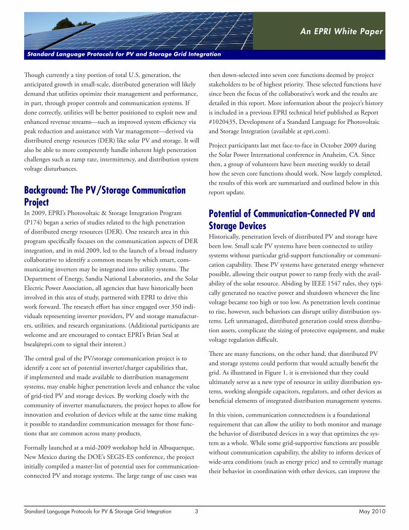
There are many functions, on the other hand, that distributed PV and storage systems could perform that would actually benefit the grid. As illustrated in Figure 1, it is envisioned that they could ultimately serve as a new type of resource in utility distribution sys-tems, working alongside capacitors, regulators, and other devices as beneficial elements of integrated distribution management systems.
In this vision, communication connectedness is a foundational requirement that can allow the utility to both monitor and manage the behavior of distributed devices in a way that optimizes the sys-tem as a whole. While some grid-supportive functions are possible without communication capability, the ability to inform devices of wide-area conditions (such as energy price) and to centrally manage their behavior in coordination with other devices, can improve the
Standard Language Protocols for PV & Storage Grid Integration 4 May 2010
An EPRI White Paper
Standard Language Protocols for PV and Storage Grid Integration
tions may be infrequent, reducing burden on the communication system. Communication path (2) may be a local network connec-tion, and may carry specific low-level commands, such as a specific power or Var setting. These commands may be frequently updated, taking advantage of the high availability and capacity of the local network.
One example of this type of architecture could be a home with an Energy Management System (EMS) console that serves as a PV system controller. This EMS may perform a number of functions such as allowing the home owner to set preferences, receiving grid-information from the local utility, and coordinating with other load or storage devices onsite. It may closely monitor the state of the inverter and provide it with specific commands.
Another example of this architecture could be a larger-scale PV in-stallation that includes a number of inverters managed by an onsite plant control system.
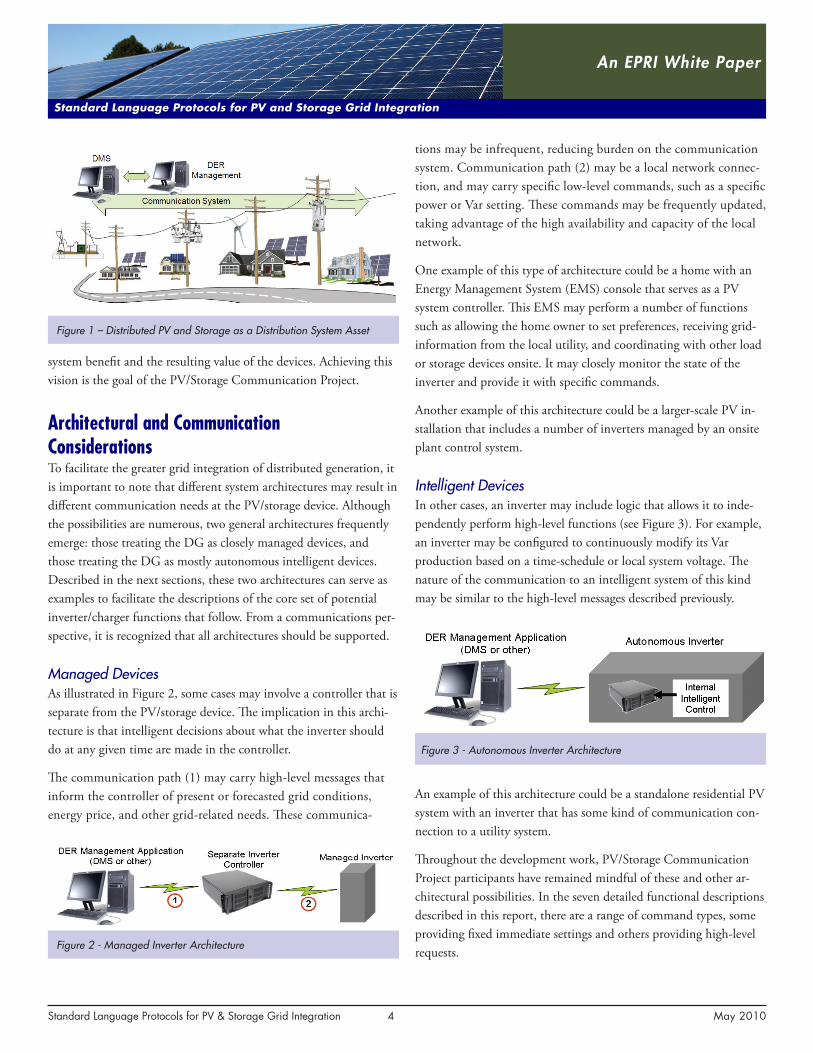
Intelligent DevicesIn other cases, an inverter may include logic that allows it to inde-pendently perform high-level functions (see Figure 3). For example, an inverter may be configured to continuously modify its Var production based on a time-schedule or local system voltage. The nature of the communication to an intelligent system of this kind may be similar to the high-level messages described previously.
An example of this architecture could be a standalone residential PV system with an inverter that has some kind of communication con-nection to a utility system.
Throughout the development work, PV/Storage Communication Project participants have remained mindful of these and other ar-chitectural possibilities. In the seven detailed functional descriptions described in this report, there are a range of command types, some providing fixed immediate settings and others providing high-level requests.
Figure 3 - Autonomous Inverter Architecture
system benefit and the resulting value of the devices. Achieving this vision is the goal of the PV/Storage Communication Project.
Architectural and Communication ConsiderationsTo facilitate the greater grid integration of distributed generation, it is important to note that different system architectures may result in different communication needs at the PV/storage device. Although the possibilities are numerous, two general architectures frequently emerge: those treating the DG as closely managed devices, and those treating the DG as mostly autonomous intelligent devices. Described in the next sections, these two architectures can serve as examples to facilitate the descriptions of the core set of potential inverter/charger functions that follow. From a communications per-spective, it is recognized that all architectures should be supported.
Managed DevicesAs illustrated in Figure 2, some cases may involve a controller that is separate from the PV/storage device. The implication in this archi-tecture is that intelligent decisions about what the inverter should do at any given time are made in the controller.
The communication path (1) may carry high-level messages that inform the controller of present or forecasted grid conditions, energy price, and other grid-related needs. These communica-
Figure 1 – Distributed PV and Storage as a Distribution System Asset
Figure 2 - Managed Inverter Architecture
Standard Language Protocols for PV & Storage Grid Integration 5 May 2010
An EPRI White Paper
Standard Language Protocols for PV and Storage Grid Integration
Communication TechniquesNumerous communication technologies may be used to integrate inverters with utility systems. The PV/Storage Communication Project team recognized that these differences exist and have been careful to identify concepts that do not depend on high system performance or special capabilities. Specifically:
• The concepts do not assume that frequent communication with inverters is required. Both high and low throughput systems are supported.
• The concepts do not assume that each inverter must or must not be individually addressed or configured.
• The concepts do not assume that the communication will or will not have broadcast or multi-cast capability.
In the smart inverter function descriptions described herein, responses are sometimes identified. It is intended that PV/storage devices will support these responses on the local communication interface, though it is recognized that certain communication systems, such as utility AMI systems, may or may not convey these responses back to the utility.
Avoiding Synchronized or Abrupt ResponsesIn some cases, a communication system may broadcast a com-mand to a large number of devices simultaneously. In such a case, it may be desirable that the devices not execute the com-mand at the same time. By spreading out the command execu-tions over time, abrupt changes to the distribution system may be avoided.
For this reason, each of the command-oriented smart inverter functions includes a time value which defines a window over which end devices may randomly delay prior to command execu-tion. Although not specifically mentioned in each description, this capability is included for each command that could result in changes to the energy flow, both real and reactive, into or out of the grid. Setting the randomization time to zero results in immedi-ate execution, and omitting it altogether results in use of a default for each function.
In addition, each command that could result in changes to energy flow to or from the grid includes a ramp rate setting that limits the rate (% per second) at which the change is to take effect.
Common Smart Inverter FunctionsAt the beginning of the PV/Storage Communication Initiative, sev-en high-priority inverter functions were identified and have defined the scope of the first version of the work. Volunteers were solicited to form a technical focus group with the charter to develop detailed descriptions for how each function should be implemented. Further, the focus group was to identify the information to be exchanged by each function and to represent this information in terms of the IEC 61850-7-420 object model for DER. The seven functions are:
1. Connect/Disconnect from Grid
2. Power Output Adjustment
3. Var Management
4. Storage Management (Charging/Discharging)
5. Event/History Logging
6. Status Reporting/Reading
7. Time Adjustment
The work of this focus group is now largely completed and the technical details for each function are documented separately in the focus group’s working document entitled: “Specification for PV & Storage Inverter Interactions using IEC 61850 Object Models and Capabilities.” The following subsections provide summary descrip-tions of each function and, where applicable, insight into the group discussion that led to each outcome.
As will become evident, project participants recognized that only the inverter can make the ultimate decision as to whether or not a particular function can be supported at a particular point in time. Many local factors, including device operating condition (health), device temperature, and battery charge level (if present), can limit the ability of a device to respond to certain commands. In this sense, the majority of the commands may be more accurately described as “requests” where the device response indicates the degree to which it was able to comply. In view of this, some of the functions, such as volt/var management, have been created entirely in the form of target settings, toward which devices independently aim.
Connect/Disconnect from Grid The grid connect-disconnect function is viewed as a command, not a request, and causes the PV inverter to physically connect or
Standard Language Protocols for PV & Storage Grid Integration 6 May 2010
An EPRI White Paper
Standard Language Protocols for PV and Storage Grid Integration
workshop, the topic was quickly recognized as being complex and was summarily listed as something to be addressed in future work.
However, as work continued, it became clear that in many cases a fixed power factor setting can work against the utility by reducing the inverter’s reactive power support as PV generation ramps down. In recognition of this fact, the focus group defined modes for both fixed power-factor setting and advanced autonomous Var manage-ment. These two modes of control are mutually exclusive, with the latest command received taking precedence over any previous setting. Each mode is therefore described as a separate functional communication.
Power Factor SettingFixed power factor will be managed through simply issuing a power factor setting. A ramp rate limiting the rate of change from the old setting to the new setting (power factor versus time) is included in the command. Also a field for a random delay time before starting is included so that broadcast commands can be issued without all PV inverters changing state at the same time.
Autonomous VAR ModesSince utilities (and/or other energy service providers) may be requesting Var support from many different PV inverters with dif-ferent capabilities, different ranges, and different local conditions, it could be very demanding of the communications systems for the utilities to issue individual commands to each PV inverter every time a change is desired. A preferred approach is for inverters to manage their own level of reactive power generation based on the capability of the inverter, configuration settings previously provided by the utility, and locally observed system voltage.
Each configured volt/var characteristic has been referred-to as a “mode” and large groups of inverters may be switched between modes with a single broadcast command. The configuration for each mode consists of an array of volt/var pairs that define a desired piecewise linear relationship between local voltage and Var genera-tion. In addition, each Mode configuration includes a Var ramp rate limit (%/second) and a randomization interval over which mode settings are to be made effective. The following modes have been identified as a starting set.
PV1 – Normal Energy Conservation Mode
This mode could be used as the normal state of operation for an inverter. As indicated in Figure 4, its Var generation is envisioned
disconnect from the grid via a switch, if it exists. A disconnect com-mand has no timeout, remaining in effect until such time as a mes-sage is received to reconnect. All systems may not have a physical disconnect switch and, consequently, will not be able to support this function. Some utilities may choose, as a result, to also utilize the power adjustment function to halt output (see next subsection).
The technical focus group considered the possibility that systems without switches could set power to zero when they receive a disconnect command. However, it was concluded that the two func-tions should remain independent and that utility control systems could execute both disconnect and “power = 0” commands if so desired. Situations such as utility system maintenance and mal-functioning inverters are examples of when a disconnect command may be used and a local manual physical disconnect may also be required.
Adjust Maximum Generation LevelThis function sets the maximum generation level (watts) as a per-centage of nameplate capacity. The command includes a duration so that max generation level reductions may be viewed as events, returning to 100% when they expire. The option of reductions with no timeout will also be handled by setting the duration to zero.
The technical focus group discussion regarding this function has emphasized the importance of preventing a device from being unintentionally left at a reduced maximum power level. Use of the event duration feature is one way to prevent this, as is the capability of systems to set an error status flag if left in a reduced state.
In addition, it was recognized that nameplate inverter capacity may be higher than actual available PV array power, depending on matching criteria. As a result, some utility experimentation may be required to determine what setting is required to achieve a target ag-gregate reduction for a particular distribution feeder or segment.
Systems that include storage capability may divert excess PV genera-tion into storage during reduction events. At the present time this setting is intended to relate only to the net output as seen by the distribution system (i.e the point of common coupling).
Power Factor and VAR ManagementThe focus group was initially given the charter to identify a means for fixed power factor control. Although the possibility of more in-telligent forms of Var management were discussed at the first project
Standard Language Protocols for PV & Storage Grid Integration 7 May 2010
An EPRI White Paper
Standard Language Protocols for PV and Storage Grid Integration
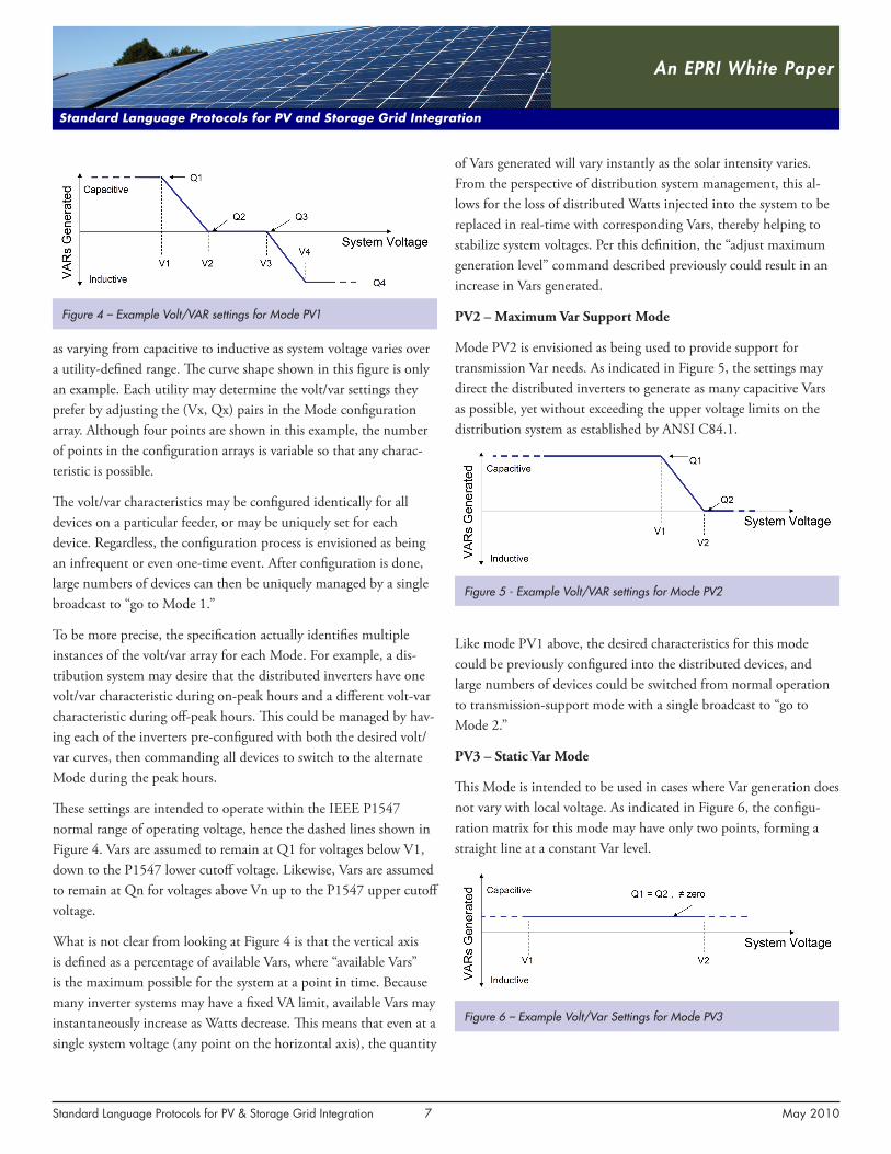
as varying from capacitive to inductive as system voltage varies over a utility-defined range. The curve shape shown in this figure is only an example. Each utility may determine the volt/var settings they prefer by adjusting the (Vx, Qx) pairs in the Mode configuration array. Although four points are shown in this example, the number of points in the configuration arrays is variable so that any charac-teristic is possible.
The volt/var characteristics may be configured identically for all devices on a particular feeder, or may be uniquely set for each device. Regardless, the configuration process is envisioned as being an infrequent or even one-time event. After configuration is done, large numbers of devices can then be uniquely managed by a single broadcast to “go to Mode 1.”
To be more precise, the specification actually identifies multiple instances of the volt/var array for each Mode. For example, a dis-tribution system may desire that the distributed inverters have one volt/var characteristic during on-peak hours and a different volt-var characteristic during off-peak hours. This could be managed by hav-ing each of the inverters pre-configured with both the desired volt/var curves, then commanding all devices to switch to the alternate Mode during the peak hours.
These settings are intended to operate within the IEEE P1547 normal range of operating voltage, hence the dashed lines shown in Figure 4. Vars are assumed to remain at Q1 for voltages below V1, down to the P1547 lower cutoff voltage. Likewise, Vars are assumed to remain at Qn for voltages above Vn up to the P1547 upper cutoff voltage.
What is not clear from looking at Figure 4 is that the vertical axis is defined as a percentage of available Vars, where “available Vars” is the maximum possible for the system at a point in time. Because many inverter systems may have a fixed VA limit, available Vars may instantaneously increase as Watts decrease. This means that even at a single system voltage (any point on the horizontal axis), the quantity
of Vars generated will vary instantly as the solar intensity varies. From the perspective of distribution system management, this al-lows for the loss of distributed Watts injected into the system to be replaced in real-time with corresponding Vars, thereby helping to stabilize system voltages. Per this definition, the “adjust maximum generation level” command described previously could result in an increase in Vars generated.
PV2 – Maximum Var Support Mode
Mode PV2 is envisioned as being used to provide support for transmission Var needs. As indicated in Figure 5, the settings may direct the distributed inverters to generate as many capacitive Vars as possible, yet without exceeding the upper voltage limits on the distribution system as established by ANSI C84.1.
Like mode PV1 above, the desired characteristics for this mode could be previously configured into the distributed devices, and large numbers of devices could be switched from normal operation to transmission-support mode with a single broadcast to “go to Mode 2.”
PV3 – Static Var Mode
This Mode is intended to be used in cases where Var generation does not vary with local voltage. As indicated in Figure 6, the configu-ration matrix for this mode may have only two points, forming a straight line at a constant Var level.
Figure 4 – Example Volt/VAR settings for Mode PV1
Figure 5 - Example Volt/VAR settings for Mode PV2
Figure 6 – Example Volt/Var Settings for Mode PV3
Standard Language Protocols for PV & Storage Grid Integration 8 May 2010
An EPRI White Paper
Standard Language Protocols for PV and Storage Grid Integration
Consistent with the previously defined modes, the vertical axis in this mode is a percentage of what is available. This is different from an absolute Var setting in that watts-generation takes precedence and Vars are generated only as possible.
Also consistent with the previously defined modes, there may be multiple configurations of the Static Var mode configuration stored in each device, allowing a single broadcast command to result in all devices shifting between pre-selected static Var levels or to/from a different mode.
PV4 – Passive Var Mode
This Mode is the same as PV3, with the exception that the Var % settings are assumed to be zero. This mode would result in behavior consistent with existing UL 1741 / IEEE P1547 compli-ant products. For consistency in configuration, the same matrix structure of volt/Var points is used here, with the Var values as-sumed to be zero.
Scheduling of VAR Modes
To further reduce burden on utility communication systems, a scheduling mechanism was defined that may be used to manage the switching between Var Modes, whenever the timing is predictable. For example, rather than issue a command twice a day to switch devices from one mode to another during a peak period, a utility may define a schedule according to which end devices may sequence through modes.
The schedule mechanism allows for variable schedule length and will be capable of repeating on a given interval. For example, a utility may establish a 24-hour mode schedule repeated daily, a 168-hour schedule repeated weekly, etc.
Storage ManagementBoth inverter providers and utilities have expressed interest in battery storage for a range of uses, including its ability to optimize output from photovoltaic systems. During the first project face-to-face workshop in Albuquerque, many interesting use cases were identified that become possible when storage capability is present. As a result, enabling storage management became one the core func-tions to be addressed by the project participants.
The focus group recognized that the information that an inverter/charger needs in order to properly manage a storage element will vary depending on how the storage is to be used. The range of uses
is broad and will likely vary with asset ownership, type of incen-tive, degree of intelligence in the inverter, and the capabilities of the communication systems employed. In order to support multiple scenarios, two types of control functions have been defined, each with immediate and scheduled versions: charge/discharge setting and price setting.
Charge/Discharge Setting The charge/discharge command provides a specific rate for battery charging or discharging. It is a simple setting that becomes effec-tive when received and remains in effect until either superseded by another command or until an optional time-out period is reached. If a time-out is specified and reached, the charge/discharge setting returns to its previous state. This direct charge/discharge command may be preferred in situations where the controlling entity and the PV/Storage system are tightly coupled, and the controlling entity frequently monitors the state of charge of the battery.
This command provides the charge/discharge rate in the form of a percentage which refers to the inverter’s nameplate charge/dis-charge capability. Positive quantities indicate charging and negative numbers indicate discharging. The nameplate capability for charg-ing may differ from the nameplate capability for discharging. For example, an inverter may be capable of delivering 3kW to the grid, but limited to a 1kW battery charging rate. In this case, a +50% setting would result in a 0.5kW rate of charging, but a -50% setting would result in a 1.5kW rate of discharge.
The actual response of the storage device will be constrained by what is possible at any time. A system cannot charge a full battery nor discharge an empty one. In this sense, this command, like many others in this specification, can be thought of as a “request,” inform-ing the end device of what action is desired.
Charge/Discharge ScheduleThis command provides PV/Storage systems with a schedule to manage charging and discharging. The schedule uses the same fundamental quantity described above, a signed value that can direct both charging and discharging, expressed as a percentage of nameplate capacity. By providing a schedule as opposed to indi-vidual charge/discharge commands, burden and dependency on a communication system can be reduced. End devices, although still tightly managed by the entity that sends the schedule, can operate for extended periods without new commands or monitoring.
Standard Language Protocols for PV & Storage Grid Integration 9 May 2010
An EPRI White Paper
Standard Language Protocols for PV and Storage Grid Integration
Additional Storage-Related SettingsIntermittency Ramp Rate Limit – This optional setting will limit the rate that watts delivered to the grid can increase or decrease in response to intermittent PV generation. The configuration will be in units of “percent of name-plate rating per second.” A single setting will be applied to both increasing and decreasing power output. This ramp rate limit does not apply to output power changes in response to commands that are received. Such commands may contain their own ramp limits. PV/Storage systems must manage the details of their battery charging such that the rate of change in power delivery to and from the grid always remains below this limit.
Storage Reserve – This optional setting specifies the minimum energy charge level allowed, as a percentage of maximum. This level may be set by the vendor, asset owner, or system operator for a va-riety of purposes. In some cases, depth of discharge may be limited in order to extend battery service life. In other cases, a minimum reserve may be desired to provide some carryover during outage. It is intended that reserve settings be maintained even while managing intermittency ramp rate limits as described above. For example, a system with a 20% minimum reserve setting may charge up to 40% before beginning to generate to the grid so that a sudden loss of the PV source can be covered by a controlled ramp-down of generation, and yet without dropping below 20% charge.
Maximum Storage Charge/Discharge Rate – This optional setting limits the rate at which energy can flow into or out of the storage element. It is provided as a percentage of nameplate capacity. Such a setting may be used to keep the storage function within desired bounds, particularly when price is being used and the charging is not being directly managed.
Event/History LoggingEvent logging was made one of the initial high-priority functions because of the great need for system and process visibility dur-ing initial field experimentation with advanced inverter functions. The availability of this log is intended to provide history data that may help diagnose system-level anomalies. A strong foundation for event/history logging already existed in the IEC 61850 and was used as the basis for this specification.
The specification does not mandate logging support for any particu-lar event type. Rather, it allows vendors to choose which to support. The specification identifies standard event codes for 23 common event types and describes how each may be handled in a standard
The schedule uses existing IEC 61850 relative-time scheduling mechanisms. These include a start-time with subsequent time entries that are relative to the start. The schedules are variable in length, allowing for any level of granularity in the charge/discharge profile. In addition, the schedule allows for a looping mechanism so that a short schedule can be used and repeated daily, weekly, or at any other interval.
Price SettingThis command provides an indicator of energy price or value. It is an immediate setting, indicating to the end device the price of energy effective at the time the command is received. The setting remains valid until it is overwritten by another price or until an optional time-out period is reached. If a time-out is specified and reached, the price setting returns to its previous value or schedule.
In some cases, the energy price might be common over a wide-area, and in others it might be locational, varying by substation, feeder, or other. Furthermore, it might be indicative of the actual energy price at the moment, or it might be more of an abstract control variable, informing devices of when the value of energy is high and when it is low.
Price information, in contrast to direct charge/discharge requests, as-sumes that the PV/Storage system has a higher level of intelligence. With price-based management, the specific decision of whether to charge or discharge, and at what level to do so, is made by the end device based on algorithms determined by the manufacturer.
Price ScheduleThe price schedule utilizes the same control quantity as the direct price setting. It provides a forward-looking view of the price, allow-ing devices to make more informed decisions in the present and to optimize the utilization of the storage element.
The structure of the price schedule is the same as that described above for a charge/discharge schedule, including looping capability. The price schedule is flexible enough to support multi-tiered time-of-use (TOU) and real-time pricing schemes like day-ahead hourly. The price command with a time-out period, as described above, can be used in conjunction with a price schedule to support critical peak pricing arrangements.
As with a simple price setting, the price schedule does not explicitly control charging and discharging, but provides intelligent systems with the information that they can use to manage their storage elements.
Standard Language Protocols for PV & Storage Grid Integration 10 May 2010
An EPRI White Paper
Standard Language Protocols for PV and Storage Grid Integration
efficient if there are a large number of items needed. To facilitate the reporting of multiple state/status items, user-defined sets may be used. Each user-defined set is created by configuring the inverter with a list of unique items. The specification requires that inverters support at least one such set. Once configured, the set can be read in the same ways as a single quantity, using any of the methods identi-fied in the next section.
Reporting Methods – On Request, On Fixed Intervals, Upon State Changes Three methods have been defined for how state/status items (or sets of items) may be reported: on request, on fixed intervals, and upon state change.
On Request: The state status may be specifically requested, allowing a person or software application to collect real-time state informa-tion at any time. Even when status information is being collected on regular intervals, there may be cases when this kind of off-cycle read is desired.
On Fixed Intervals: Inverters may be configured to repeatedly re-port any single item or set of items. The interval time is configurable as is the ability to randomize the exact time of transmission so that all devices do not report at the same time.
Upon State Changes: Bounds may be set for any item such that it is automatically reported if the value goes outside the set range. If the item is part of a defined set, then the entire set is reported rather than just the single item. Some communication systems may not support the unsolicited reporting of data, however.
Time Adjustment This function is being defined to work in alignment with NIST standards for time adjustment. The system will likely use the Net-work Time Protocol (NTP) (RFC-1305) or Simple Network Time Protocol (SNTP) (RFC 1305) between the controlling entity (utility or customer EMS) and the PV inverter to set time.
Next StepsEPRI, together with the Department of Energy, Sandia National Laboratories, and the Solar Electric Power Association, intends to continue this initiative, with results to be contributed to standards organizations. Project participants will soon be working to identify the set of enhancements and functions to be addressed in phase 2. Going forward, it is envisioned that this function-selection process
way, if so elected by the vendor. In addition, the specification allows for manufacturer-specific events to be logged.
Each log entry includes the following information:
1. The date and timestamp of the event
2. A data reference (identification of the quantity that triggered the event)
3. The data value (the value of the quantity that caused the event)
4. An event code (a standardized number that is unique to this type of event, but not unique to this specific occurrence)
5. An optional text field containing supporting information (the content of this text field, if used, is not controlled by the specifi-cation)
These logs will be maintained by PV/Storage devices in a circular file that will overwrite itself as new events are added. The logs can be read by a request that specifies “all events,” “events from time xx to time yy,” or “events from time xx to most recent event.” In addition, an event log read- request can identify specific event types, limiting the data exchanged over the communication system only to that which is necessary.
State/Status ReportingThe state/status reporting function is intended to collect the current operational state of the PV/Storage system. The approach for state/status reporting is similar to event/history logging in that vendors will choose which to support in their products. This specification provides a standard means in which a base set of quantities may be reported, if so chosen by the vendor.
A starting set of 31 standardized state/status items are identified in the specification. These cover several categories including overall sys-tem state, PV related status, storage related status, setpoints, power measurements, and nameplate information.
Several reporting mechanisms have been defined for state/status information, including both single items and sets of items, as well as reporting on-demand, on fixed interval, and upon value change.
Single Items and User-Defined Sets State/status items may be requested and reported individually, with each being identified by its unique ID. This however, may not be
Standard Language Protocols for PV & Storage Grid Integration 11 May 2010
An EPRI White Paper
Standard Language Protocols for PV and Storage Grid Integration
Coordination with NIST Priority Action PlansThis project has been conducted in coordination with ongoing NIST Smart Grid interoperability activities. Most significantly, the project relates to Priority Action Plan (PAP) 7, which is working on standards for storage integration, but is also considering distributed PV, taking advantage of obvious use-case similarities. The use cases resulting from the first phase of this project were contributed to PAP7. This activity is aligned with the work of the IEEE Standards Coordinating Committee 21 which addresses distributed resources and was the sponsor of grid integration work in the P1547 series of distributed resource interconnection standards. Coordination of the work of this project with the existing and emerging work of IEEE SCC21 needs to be expanded.
This project will also be contributing to PAP 12 which addresses standard methods for mapping the IEC 61850 object models to the DNP3 protocol. It is intended that the mapping of these 61850-based functions to standard DNP3 messages can serve as a live-application to accelerate and evaluate the method developed by PAP 12. This coordination is in process.
Testing of Devices against the SpecificationAfter appropriate standards organizations have taken ownership of the specification, there remain the questions of who and how to test products for compliance and interoperability. Historically, Underwriters Laboratories (UL) has filled a primary role in this area and inverter testing against the UL 1741 standard is common. Going forward, it is anticipated that product compliance organiza-tions like UL will continue in this role with expanded testing to cover advanced inverter functionality and communication protocol compliance.
In the near term, it may also be necessary to develop test protocols and conduct interoperability tests on prototypes prior to deploy-ment into utility pilot programs. The Department of Energy and Sandia National Laboratories have developed a plan to expand existing inverter test facilities to include evaluation for the functions described by this specification. Verification of communications may be readily conducted in many labs, but the more extensive equip-ment required to test the effect on the grid connection is less com-mon. Collaboration will be needed from EPRI, NREL, and Sandia National Laboratories to provide resources, facilities, and testing during the near-term.
will be informed by modeling and field trials of the completed work. In addition to continuing with new functions, several follow-up tasks are planned, including mapping to communica-tion protocols, coordination with NIST Priority Action Plans, and establishment of test facilities for compliance and interoperability testing.
Mapping to Communication ProtocolsThe seven high-priority functions described in this report indicate a wide range of specific information that is to be exchanged between the controlling entity and the field devices. Although not shown in this document, each piece of information has been represented in terms of IEC 61850 object models, as defined for distributed energy resource systems. Where gaps were found, the needed extensions to the IEC 61850 standard were documented and will be provided to the IEC TC57 working group 17 as a contribution for consideration in the next release of the standard.
The next planned step is to map these data, and the functions they represent, into communication protocols in a standardized way. Based on surveys and discussion from previous workshops, this project intends to do this mapping to two protocols in particular: DNP3 and Smart Energy Profile 2.0.
DNP3DNP3 protocol was preferred for those systems that may be inte-grated as nodes in a field or distribution system network. It is con-sistent with the NIST Priority Action Plan 12 to perform mappings from the IEC 61850 objects to DNP3 messages. The effort to do this for these functions will be coordinated, to the extent possible, with this NIST activity, ideally becoming a direct contribution to the overall effort. This task is currently underway.
Smart Energy Profile 2.0The Smart Energy Profile (SEP) was preferred for those systems that may be integrated as nodes in a home area network. Although SEP began as a Zigbee-specific application profile, plans have been made to make it an IEC standard that could run over any network. It is anticipated that the mapping of these functions into the SEP 2.0 specification can be done as a contribution to the version 2.0 effort. Help is needed from the Smart Energy Profile developers on this task.
The Electric Power Research Institute, Inc. (EPRI, www.epri.com) conducts
research and development relating to the generation, delivery and use
of electricity for the benefit of the public. An independent, nonprofit
organization, EPRI brings together its scientists and engineers as well as
experts from academia and industry to help address challenges in elec-
tricity, including reliability, efficiency, health, safety and the environment.
EPRI also provides technology, policy and economic analyses to drive
long-range research and development planning, and supports research
in emerging technologies. EPRI’s members represent more than 90 per-
cent of the electricity generated and delivered in the United States, and
international participation extends to 40 countries. EPRI’s principal
offices and laboratories are located in Palo Alto, Calif.; Charlotte, N.C.;
Knoxville, Tenn.; and Lenox, Mass.
Together . . . Shaping the Future of Electricity
1020906 May 2010
Electric Power Research Institute 3420 Hillview Avenue, Palo Alto, California 94304-1338 • PO Box 10412, Palo Alto, California 94303-0813 USA800.313.3774 • 650.855.2121 • [email protected] • www.epri.com
© 2010 Electric Power Research Institute (EPRI), Inc. All rights reserved. Electric Power Research Institute, EPRI, and TOGETHER . . . SHAPING THE FUTURE OF ELECTRICITY are registered service marks of the Electric Power Research Institute, Inc.
EPRI Resources
Brian Seal, Sr. Project Manager, EPRI865.218.8181, [email protected]
Enabling Integration of Distributed Renewables (Program 174)
Invitation to ParticipateThe research effort to develop a standard language for com-municating with inverter-based systems such as storage and photovoltaics, is being conducted as an open industry collab-orative. Product suppliers, utilities, regulators, and research institutions are all welcome to participate in or simply moni-tor the project. To be added to the correspondence distribu-tion list, please contact Brian Seal at [email protected].


