69
STANDARD PIPE & LINE PIPE ITT Grinnell

Standard PiPe & Line PiPe
ITT Grinnell

C O N T E N T S
General information 3
Facilities 8
Product Properties 21
Comparative Specifications 24
Pipe tables 41
Glossary 65
disclaimer
all material contained in this publication is for general information only. this material should not, therefore, be used or relied upon for any specific application without independent competent professional examination and verification of its accuracy, suitability and applicability. anyone making use of the material does so at their own risk and assumes any and all liability resulting from such use. ITT GrinnellProducts disclaims any and all expressed or implied warranties of merchantability and/or fitness for any general or
particular purpose.
2

Gen
eral
Info
rma
tion
ITT Grinnell Products
GeneraL inFOrmatiOn
ITT Grinnell employees are deeply committed to being
easy to do business with anywhere in the world. As an
industry-leading manufacturer, our focus is to offer the
widest range of products and to exceed your expectations for
on-time delivery, easy installation, performance and
operating efficiency.
Our Mission: To be the market leader in the development,
manufacture and worldwide sale of quality air moving and
control equipment with total commitment to the customer.
Our commitment to our customers is what drives our long-
standing sustainability practices. We continuously strive to
reduce energy usage and other production costs to ensure
competitive prices for you and ongoing business success. We
support the health, safety and training of our employees to
achieve the high quality product performance you expect
from ITT Grinnell — and deserve. And we take on the
industry’s most complex challenges by introducing
innovative new product solutions to meet your future needs.
3

Sizes and Grades ITT Grinnell Products provides seamless and electric resistance welded pipe in Od sizes ranging from ۱/۲ inches to ٤۸ inches. a variety of end finishes, lengths, grades and wall thicknesses are available. to ensure the absolute highest quality, ITT Grinnell Products has implemented a Quality management System in full compliance with aPi Q1 and TUV , .ITT Grinnell Products maintains aPi licenses to manufacture and monogram products to aPi specifications 5Ct and 5L. in addition, Fairfield tubular Operations, Lorain tubular Operations, mcKeesport tubular Operations and texas tubular Operations manu-facturing facilities are all TUV certified. a full line of aPi grades and proprietary grades are produced to meet specialized customer needs, including HiC-resistant pipe for use in H
2S
environments and pipe grades with superior impact properties even under extremely cold arctic conditions.
the steels of today are far more sophisticated than metals of earlier eras. the addition of alloys, plus an array of field-testing, lab-testing, melting, casting and hot-rolling practices, along with specialized heat treatments, have created steels that are precisely crafted to meet and/or exceed demanding product requirements. ITT Grinnell innovative software applications calculate, measure, test, record and analyze every aspect of the modern steelmaking process. at ITT Grinnell , we use cutting-edge technology to manage every aspect of production. real-time communication between control room and machine operators allows for precise regulation of each step of the process, from charging furnaces with raw ingredients to controlling temperatures, timing, alloying, flows, testing and transport. ITT Grinnell commitment to the tubular busi-ness is even stronger today than it was when we went into the business more than a century ago. Upgrades to our facilities and investments in new technology give us the latest tools to provide our customers with consistent high-quality products.
Sizes and Grades Chart
Type of Pipe Regular Mill Production
Size Range, NPS
Size Range, Inches
Wall Thickness Range, Inches
Max. Length, Feet
Seamless 1.5 - 26 1.900 - 26 Od 0.140 - 2.312 48
electric resistance Weld 2 - 20 2.375 - 20.000 Od 0.154 - 0.625 80
Gen
eral
Info
rma
tion
4

Gen
eral
Info
rma
tion
Grades of steel vary in chemical composition from simple carbon manganese to complex multi-element micro-alloyed composition. Precise control of compositions and manufactur-ing processes allows for the manufacture of tubular products with a wide variety of properties and attributes. When selecting the proper material Specification, Pipe Grade, aStm Special requirement, aPi 5L Product Service Level (PSL), aPi 5L annex requirement or CSa Z245.1 Category or Service Group, the end use and method of pipe fabrica-tion should be considered. Various practices are employed in all phases of steel production, which determine the type and quality of the finished product.
5

USS m1020 Plain end erW Pipe for Water Well applications
USS m1021 Plain end erW Pipe for Use in Structural applications
USS m1024 Seamless mechanical tubing in Sizes from nPS 2 thru 26
USS m1029 Plain end Seamless Pipe for Use in General Purpose applications
USS m1400Constructional alloy Steel Seamless mechanical tubing – Grades USS “t-1” type a and USS “t-1” type B
USS m1407 erW Pipe nPS 8 thru 12 for Lift devices
USS m1430 Seamless Steel Slurry Pipe - Grade USS 430
USS m1431 Seamless Slurry Pipe to be Heat treated. Primarily for mechanical Joining
USS m1470 Seamless Steel Pipe for Fabrication into Ordinary Welding Fittings
USS m1471 Seamless Steel Pipe for Fabrication into High-Strength Welding Fittings
USS m1475 Seamless Steel Pipe for manufacture of Cold-Formed Fittings
USS m2430 erW Pipe intended for transportation of Solids in Slurry Form
Pressure Determinations
Barlow’s Formula is commonly used to determine the following:• internal Pressure at minimum Yield• Ultimate Burst Pressure• maximum allowable Operating Pressure, and• mill Hydrostatic test Pressure
this formula is expressed as P = , where:
P = pressure, psigt = nominal wall thickness, inchesd = outside diameter, inchesS = allowable stress, psi
to illustrate, assume a seamless piping system 8-5/8” Od x 0.375” wall specified to aPi 5L Grade B which has a specified minimum yield strength (SmYS) of 35,500 psi and a specified minimum tensile strength (SmtS) of 60,200 psi.
Internal Pressure at Minimum Yield
S=SmYS (35,500 psi)
and
P= = = 3,087 or 3,090 psig (rounded to nearest 10 psig)
2Std
ITT Grinnell material Standards ITT Grinnell material standards are specifications not covered by a society, association or other specify-ing body. the following includes the material standards used most frequently for tubular applications.
2 (35,500) (0.375)8.625
2Std
Gen
eral
Info
rma
tion
6

Ultimate Burst Pressure at Minimum Tensile
S = SmYS (60,200 psi)
and
P = = = 5,234.7 psig or 5,230 psig (rounded to nearest 10 psig)
Maximum Allowable Operating Pressure (MAOP)
S=SmYS (35,500 psi) reduced by a design factor, for example 0.72,
and
P = = = 2,222.6 psig or 2,220 psig (rounded to nearest 10 psig)
Mill Hydrostatic Test Pressure
S=SmYS (35,500 psi) reduced by a factor depending on Od and grade (0.60 for 8-5/8” Od Grade B)
and
P = = = 1,852.2 psig or 1,850 psig (rounded to nearest 10 psig)
Some safety codes and regulatory agencies also assign a longitudinal joint factor to account for weld efficiency. the more common are 0.85 for erW pipe and 0.60 for CW pipe. Seamless pipe enjoys a joint factor of 1.00. this means that some designers consider erW pipe as 85 percent as efficient as seam-less pipe and CW pipe only 60 percent as efficient for the same application. therefore, for a given application, erW pipe would require a heavier wall than seamless pipe, and CW pipe, in turn, would require a heavier wall than erW pipe.
distributors who stock pipe in a combination of seamless, erW, and CW must exercise extreme care to see that pipe with joint efficiency factors of 0.85 or 0.60 is not used on jobs which require pipe with a joint factor of 1.00.
Wall Thickness
Barlow’s Formula is also useful in determining the wall thickness required for a piping system. to illustrate, assume a piping system has been designed with the following criteria:
1. a working pressure of 2,000 psig (P)2. the pipe to be used is 8-5/8” Od (d) specified to aPi 5L Grade B (SmYS = 35,500 psi)
rearranging Barlow’s Formula to solve for wall thickness gives:
t = = = 0.243 wall
Wall thickness does not affect the outside diameter; only the inside diameter is affected. For example, the outside diameter of a one-inch extra-strong piece of pipe compared with a one-inch standard weight piece of pipe is identical; however, the inside diameter of the extra-strong is smaller than the inside diameter of the standard weight because the wall thickness is greater in the extra-strong pipe.
2 (60,200) (0.375)8.625
2Std
2 (35,500 x 0.72) (0.375)8.625
2Std
2 (35,500 x 0.60) (0.375)8.625
2Std
(2,000) (8.625)2 (35,500)
Pd2S
Gen
eral
Info
rma
tion
7

FACILITIES
8

Fairfield, alabama - 4-1/2” to 9-7/8” Od Seamless manufacturing Process
Cast Round Billets Rotary Piercing Mill (RPM)
Round Reheating Mandrel Mill
Shell ReheatingCooling Bed Stretch Reducing Mill
Batch Saws
NDT Inspection In-Process Storage
Fairfield tubular Operations can produce approximately 840,000 net tons of seamless tubular products every year. the process begins with solid steel rounds, or billets, being cut to a specified length and sent through a walking-beam reheat furnace, where temperatures reach nearly 2,300°F. the yellow rounds are turned into a tube shell in mere seconds in the rotary piercing mill as the preheated billets are cross-rolled between two barrel-shaped rolls at a high speed. the seamless shells enter Fairfield’s seven-stand mandrel mill, where they are rolled over a retained mandrel to provide the needed Od size
and wall thickness for the next process. the process is carefully monitored using a state-of-the-art hot-wall measuring system. the shells are then reheated for final forming in a 24-stand stretch-reducing mill, where outside diameters are formed to customers’ exacting specifications. Wall thickness is again verified using a hot-wall measuring system. after being rotated and advanced on the walking-beam cooling bed, the pipes are batch cut and transferred to an in-process storage area, where they are handled by computer-controlled gantry cranes.
manufacturing: Seamless Od range: 4-1/2” to 9-7/8”Walls: 0.205” to 1.200”Lengths: SrL, drLGrades: aStm a 106B/a53 B, aPi5L Grade B, X42, X52, X60, X65, X70, aStm a333, CSa Z245.1 Grades 241 thru 483
Cut-Off Facilities Facilities
Facilities
9

Austenitizing Furnace
Sizing MillHot Straightener
Quenching Unit Tempering Furnace
Cooling Bed
Straightening
Hydrostatic Testing
NDT Inspection
Facing and Beveling
Final Inspection
From this in-process storage, pipe can be delivered to one of three primary workstations: heat treating, finishing or special pipe processing. depending on grade, pipe might undergo quenching and tempering to alter its micro- structure to improve strength or other properties. Quenching and tempering controls hardness, reduces brittleness, and brings the steel to tensile and yield strengths required for the specified grade. Seamless pipe that has not been quenched and tempered passes initially through a straightener and then a non-destructive testing (ndt) unit. (Q&t pipe goes directly to the ndt area.)
electromagnetic inspection (emi) detects longitudinal and transverse flaws as the pipe moves though a set of coils. Ultrasonic testing is used to verify wall thickness. Grade/composition is verified on each pipe by eddy current. all pipe is hydro-tested. Finished pipe is weighed, measured, stenciled with a unique identification, coated and loaded onto rail cars for shipment to customers.
Facilities
Cut-Off Facilities
Heat treating
Finishing
10

mcKeesport, Pennsylvania - 8-5/8” to 20” Odelectric resistance Weld manufacturing Process
Coil Feed Ramp Fin Pass SectionFirst Forming Section
High Frequency Welder
Sizing Mill Seam NormalizerAir Cooling & Water Cooling
Weld Seam Ultrasonic Inspection
Flying Cut-Off
mcKeesport tubular Operations sits on the original site of national tube Works. mcKeesport has been making tubular products since the 1870s and electric-resistance weld pipe since 1964. Steel arrives at the facility in coils that are unrolled, cut and welded into a continuous strip before entering the mill. the strip steel passes through a series of forming rolls, which transform the strip from flat steel to a round pipe section. the fin pass section of the mill finishes the rounding process and contours the edges of the strip for seam welding. the high-frequency welder heats the edges of the rolled strip to approximately 2,600°F. Pressure
rolls then squeeze the heated edges together to form a fusion weld. the weld is inspected by an ultrasonic non-destructive inspection unit. the pipe then enters the seam normalizer where the weld area is heat treated as per aPi specification to remove welding stresses and produce a uniform normalized grain structure. the weld is cooled in air below transformation temperature and then water-cooled to near ambient before passing through the sizing mill, where idler side-closing rolls straighten the pipe and size it to the correct outside diameter. as the continuous length of pipe moves down the mill, the flying cut-off cuts lengths of pipe
manufacturing: electric resistance Weld Od range: 8-5/8” to 20”Walls: 0.188” to 0.406”Lengths: SrL 18’-22’; drL 39’-45’; trL 33’-65’; QrL 42’-80’ max Grades: aStm a53 B, aPi5L Grade B, X42, X52, X60, X65, X70, aStm a523 a (cable pipe), CSa Z245.1 Grades 241 thru 483
Facilities
11
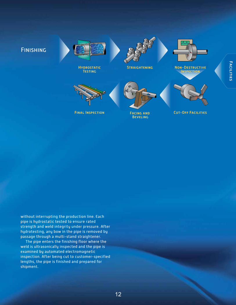
Facilities
Final Inspection Cut-Off Facilities
Hydrostatic Testing
Straightening
Finishing
Non-Destructive Inspection
without interrupting the production line. each pipe is hydrostatic tested to ensure rated strength and weld integrity under pressure. after hydrotesting, any bow in the pipe is removed by passage through a multi-stand straightener. the pipe enters the finishing floor where the weld is ultrasonically inspected and the pipe is examined by automated electromagnetic inspection. after being cut to customer-specified lengths, the pipe is finished and prepared for shipment.
Facing and Beveling
12

Lone Star, texas - mill no. 1 - 8-5/8” to 16” Odelectric resistance Weld manufacturing Process
Full-Body Normalize
Hot Reduce Cool
ITT Grinnell Operations mill no. 1 manufactures high-quality erW tubular products primarily for the oil and gas industries. Steel arrives at the facility in coils slit to precise width before the manufacturing process begins. the strip steel is uncoiled, leveled, conveyed through a side trimmer, which shears both edges to provide proper width and clean surfaces for welding. the strip then passes through a series of forming rolls, which transform the coil from a flat strip of steel to round pipe sections. the edges of the strip are contoured for seam welding. the weld is created by heat obtained from the pipe’s
resistance to the flow of electric current of the circuit of which it is part, and by applied pressure to form a forged weld. no filler metal is used in the welding process. after the flash (metal extruded by the weld process) is removed from the pipe’s inside and outside surfaces, the pipe is cut to length by a flying rotary cutoff. Weld integrity is checked by ultrasonic test equipment in line behind each welder. the pipe passes through a series of induction heating furnaces where the entire pipe is heated to temperatures above 1,650°F and allowed to air cool. this full-body normalizing operation
manufacturing: electric resistance Weld Od range: 8-5/8” to 16”Walls: 0.250” to 0.562”Lengths: SrL, drL, trLGrades: aStm a53 B, aPi5L Grade B, X42, X52; Q&t Grades: X60, X65, X70, X80
Uncoil & LevelFlash Trim
UST & Cut ER Weld Cage Mill Form Edge Trim
Coil
Facilities
13

Straighten Hydrostatic TestBevel
Final Inspection
Weld USTPipeimage®Full Body UST
Weigh, Measure, Stencil & Ship
Upon Agreement Only
Facilities
produces uniform grain structure throughout the entire pipe wall. the normalizing furnaces may also heat the pipes for diameter reduction and a more uniform finished product. after cooling, pipe is sized, straightened, visually inspected, stenciled with the appropriate identity and queued for finishing. Laboratory tests confirm full compliance to specifications and other mechanical property requirements before the pipe is beveled, electromagnetically inspected and hydrostatically tested. multiple certifications are available.
NDT Inspection
Cut-Off Facilities
Facing and Beveling
14

Lone Star, texas - mill no. 2 - 2-3/8” to 6-5/8” Odelectric resistance Weld manufacturing Process
Uncoil & LevelFlash Trim
UST & Cut ER Weld Form Edge Trim
Full-Body Normalize
Hot Stretch Reduction
Cool
Coil
ITT Grinnell Operations mill no. 2 manufactures high-quality erW tubular products primarily for the oil and gas industries. Steel arrives in coils slit to precise width. the strip steel is uncoiled, leveled, conveyed through a side trimmer, which shears both edges to pro-vide proper width and clean surfaces for welding. the strip then passes through a series of forming rolls, which transform the coil from a flat strip of steel to round pipe sections. the edges of the strip are contoured for seam welding. the weld is created by heat obtained from the pipe’s resistance to the flow of electric current of the circuit of which it is part, and by applied pressure to form a forged weld. no filler metal is used in the welding process.
after the flash (metal extruded by the weld process) is removed from the pipe’s inside and outside surfaces, the pipe is cut to length by a flying rotary cutoff. Weld integrity is checked by in-line ultrasonic test equipment. the pipe then passes through a series of induction heating furnaces where the entire pipe is heated to temperatures above 1,650°F and allowed to air cool. this full-body normalizing operation produces uniform grain structure throughout the entire pipe wall. the normalizing furnaces also heat the pipes for diameter reduction and a more uniform finished product. Grades X60 through X80 require heat treatment and quenching. (this additional process is not shown in the flow diagram.)
manufacturing: electric resistance Weld Od range: 2-3/8” to 6-5/8”Walls: 0.154” to 0.531”Lengths: SrL, drL Grades: aStm a53 B, aPi5L Grade B, X42, X52; Q&t Grades: X60, X65, X70, X80
Cut-Off Facilities
Facilities
15

Straighten Hydrostatic TestBevel
Eddy CurrentWeigh, Measure, Stencil & Ship
Final Inspection
Finishing2-3/8” - 4”
Finishing4” - 6-5/8”
Straighten
Hydrostatic Test
Eddy Current
Final Inspection
Weld USTPipeimage®Full Body UST
Weigh, Measure, Stencil & Ship
Bevel
Upon Agreement Only
Facilities
after cooling, pipe is straightened, visually inspected, stenciled with the appropriate identity and queued for finishing. in the finishing department, the pipe is beveled, eddy current inspected and hydrostatically tested. Full-body electromagnetic and ultrasonic testing is avail-able for pipe sizes 4” and larger. Laboratory
Cut-Off & Re-Bevel (As Needed)
Cut-Off & Re-Bevel (As Needed)
tests confirm full compliance to specifications and other mechanical property requirements. multiple certifications are available.
16

Rotary Billet Heating
Reheat FurnacePlug Rolling Mill
Rotary Piercing Mill (RPM)
Second Piercing (Elongator)
Lorain, Ohio - mill no. 3 - 10-3/4” to 26” OdSeamless manufacturing Process
Cast Round Billets
Rotary Expanding Mill
Reheating Furnace
Sizing MillReeling Mill
Lorain mill no. 3 manufactures superior seamless pipe, beginning with the processing of continuous cast round billets using the latest steelmaking technology. the cast round billets begin their journey in the rotary hearth furnace where temperatures exceed 2,300°F. the preheated round billets are processed through a piercing mill to form a pierced billet or shell. the hot shell is then run through a second piercing mill and a plug rolling mill to increase diameter and length, and to reduce and improve the uniformity of the wall thickness. as the billet goes through the first piercer, it is gripped by rolls, which rotate and advance it over the piercer point, forming a hole through its length. the
second piercing mill further increases the diameter and length of the shell and reduces the wall thickness. the pierced hot shell passes through the plug rolling mill to again reduce the wall thickness and to increase the length. Pipe larger than 16” Od is reheated and sent through a rotary rolling mill, which uses large discs to expand the hot pipes up to 26” in diameter. rotary rolling can produce pipe as long as 48 feet. the pipe then passes through the reeling and sizing mills. the reeling mill grips the pipe and advances it over a mandrel, burnishing the inside and outside surfaces. after moving through an intermediate cooling station, the pipe proceeds on one of two paths.
manufacturing: Seamless Od range: 10-3/4” to 26”Walls: 0.365” to 2.312”Lengths: SrL, drLGrades: aStm a 106B/a53 B, aPi5L Grade B, X42, X52, X60, X65, X70, aStm a333, CSa Z245.1 Grades 241 thru 483
Reheat Furnace
Direct Roll 10.75”-16”
Rotary Roll 16”-26”
Facilities
17

Facilities
Cooling Bed Rotary Straightener
Hydrostatic Testing
NDT InspectionFacing & Beveling
Finishing
Final Inspection
if the steel is an as-rolled carbon grade prod-uct, it is heat-equalized in a walking-beam reheat furnace and then sent through a three-stand sizing mill to reach final outside dimension. if the steel requires heat treating, the reheat furnace’s temperature is raised to austenitize the pipe. the steel exits the furnace and passes through a state-of-the-art Od/Od-id quench and walking-beam temper furnace (not pictured) before rejoining the main production line to pass through the three-stand sizing mill. after sizing, the pipe is allowed to cool on slowly moving conveyor tables in preparation for straightening. For products that require hot straightening, these cooling tables are bypassed and the pipe is sent directly from the sizer to the straightener.
the pipe is then ready for finishing. the pipe undergoes ndt inspection to detect any body wall imperfections. any imperfections are proved up and dispositioned in accordance with specified tolerances. after inspection, an expanding arbor holds the pipe in line while a revolving head faces and bevels the end of the pipe. the finished pipe is visually inspected and subjected to a hydrostatic test as a strength and leak check before shipping. When required by specification or customer order requirements, the pipe is processed through one of several offline Ut and special end area inspection units.
Cut-Off Facilities
18

Lorain, Ohio - mill no. 4 - 1.900” to 4-1/2” OdSeamless manufacturing Process
Rotary Hearth Furnace
Mandrel MillPiercing Mill Reheat Furnace
Run-Out/Finishing
Cooling BedBatch Sawing Stretch Reducing Mill (SRM)
the process at Lorain mill no. 4 begins with continuous cast 6” round billets being heated in a rotary hearth furnace to proper temperature for piercing. the heated billets are center punched and pierced by advancing the billet over a piercer point in the piercing mill. the pierced billet or shell is transferred to a mandrel mill and rolled over a solid mandrel where the Od is reduced and the length is increased. the shell is then reheated to proper rolling tempera-ture in preparation for the final rolling process. the hot shell is run through a descaling unit to prepare the Od surface for rolling and run through the stretch reducing mill. at this stage, the final Od and wall thickness are established for the pipe.
after exiting the stretch reducing mill, the pipe is allowed to cool on a walking-beam cooling bed. Sample inspections are also conducted at this point. after cooling, the pipe is batched, stenciled and sawed to the specified length. the sawed pipe is then transferred to a run-out table and moved to finishing. Pipe ends are faced on dual automatic facers, pipe is hydrotested and sample inspections are done. Upsetting, heat treating, additional inspec-tion and hydrotesting are done to meet customer specifications at ITT Grinnell Houston tubular Processing Services operation or at the Lorain no. 6 Q&t and Finishing Complex. the new no. 6 facility can heat treat and finish pipe Ods from 2.375” thru 7.625”.
manufacturing: Seamless Od range: 1.900” to 4-1/2”Walls: 0.140” to 0.674”Lengths: SrL and drLGrades: aStm a 106B/a53 B, aPi5L Grade B, X42, X52, X60, X65, X70, aStm a333, CSa Z245.1 Grades 241 thru 483
Facilities
19

Lorain, Ohio - mill no. 6 - 2-3/8” to 7-5/8” OdQuench and temper and Finishing Process
Austenitizing Furnace
Tempering FurnaceQuenching Unit Straightening
Cut-Off Facilities NDT Inspection & Sea
Weld Seam UT Inspectionfor ERW pipe
Hydrostatic Testing
Facing & Beveling Grade Comparer Weigh, Measure,Stencil, Coat & Ship
manufacturing: Seamless & electric resistance Weld Od range: 2-3/8” to 7-5/8”Walls: 0.205” to 0.812”Lengths: 20’ to 48’Grades: aStm a 106B/C, a53 B, a333 Grades 1 and 6, aPi5L B, X42, X52, X60,
X65, X70, aStm a333, CSa Z245.1 Grades 241 thru 483
Final Inspection
the no. 6 Quench and temper and Finishing Facility was built in 2011. the facility processes pipe from 2.375 to 7.625 inches in outside diameter, with a wall thickness of up to 0.812 inches, and to a maximum finished pipe length of 48 feet. Green tubes to be heat treated arrive in railroad cars and are loaded on to a charge table with the use of a magnet crane. Pipe is conveyed into the austenitizing furnace, heated to the required temperature and then cooled with an Od water quench to below 200°F. after entering the tempering furnace, precise control of the temperature is used to control the mechanical properties along the length of the pipe. Pipe travels through a 100-ton, 6-roll opposing straightener and then on to a walking-beam cooling bed.
the finishing portion of the facility starts with a combination emi/Ut unit and an Sea inspection unit where longitudinal and transverse flaws can be detected and wall thickness can be verified. each pipe is then hydrostatically tested to ensure rated strength under pressure. erW pipe undergoes an additional test when the weld seam is inspected with an in-line Ut inspection unit. after testing is complete, the pipe is sent through the finishing process. Before shipment to the customer, pipe is grade-verified, length measured, weighed, stenciled and coated.
Facilities
20

PRODUCTPROPERTIES
21

Pro
du
ctP
roperties
PrOdUCt PrOPertieS
ITT Grinnell Products manufactures both seamless and welded pipe to meet specific customer requirements. advanced manufacturing techniques and controls ensure high quality, uniform, economical products. a complete range of Ods, end finishes and lengths are available.
Seamless Standard Pipe and Line Pipe ITT Grinnell Products manufactures its seamless pipe by piercing solid billets of fully killed steel. this “seamless” method of manufac-ture is a forging operation that only the soundest, toughest steel can tolerate. Chemical and mechanical property require-ments are as prescribed by current aPi, aStm,
aSme and applicable CSa standards. ITT Grinnell Products is the only domestic producer of seamless pipe in the 11-3/4” to 26” Od size range. ITT Grinnell Products provides seamless Standard Pipe and Line Pipe for a wide range of applications. Our seamless pipe has an unsurpassed record of safety, and uniform strength and ductility, making it the product of choice for critical applications. Standard Pipe is widely used primarily in the construction, refining, chemical and petro-chemical industries. Line Pipe is used for the transmission of crude oil, natural gas and petro-leum products as well as for water and slurry pipeline applications.
Availability – Standard Diameters and Walls
Size1 Wall Thickness,2 Inches
NPS OD (Inches) Lorain, OH Fairfield, AL
1 1/2 1.900 0.140-0.281 -
2 2 3/8 0.154-0.436 -
2 1/2 2 7/8 0.160-0.552 -
3 3 1/2 0.170-0.600 -
3 1/2 4 0.180-0.650 -
4 4 1/2 0.188-0.674 0.205-0.750
5 5 9/16 - 0.250-0.750
6 6 5/8 - 0.250-0.870
8 8 5/8 - 0.250-1.200
10 10 3/4 0.307-2.000 -
12 12 3/4 0.330-2.312 -
14 14 0.375-2.000 -
16 16 0.375-2.000 -
18 18 0.375-1.562 -
20 20 0.375-1.512 -
22 22 0.375-1.375 -
24 24 0.375-1.250 -
26 26 0.375-1.125 -
1 Sizes between nPS 1 1/2 and 26 not listed subject to inquiry.
2 maximum wall varies for grades over X42 and is subject to mill inquiry.
22

electric resistance Weld (erW) Standard Pipe and Line Pipe ITT Grinnell Products’ erW Standard Pipe and Line Pipe are smoothly finished, thin-walled, extra-long products produced by continuously forming coiled bands and welding the longitudinal seam using high-frequency electric resistance welding. Chemical and mechanical property requirements are as prescribed by current aPi 5L and applicable aStm standards. erW Standard Pipe and Line Pipe are widely used throughout the oil and gas industry, as well as for pipe piling, pipe-type cable systems and hydraulic hoists.
Characteristics and AdvantagesEighty-Foot Lengths – Ultra-long lengths of ITT Grinnell Products erW pipe, available from mcKeesport tubular Operations minimize
handling time in transportation and installation, and significantly reduce field welding labor, time and costs.
Smooth Surfaces – ITT Grinnell Products hot rolled strip steel is continuously cold formed into smooth-surfaced, uniform-gage pipe for superior flow characteristics.
Stronger, Lighter Walls – the improved, higher strength, lighter gage steel bands used by ITT Grinnell Products are fused by high- frequency electric resistance welders into rugged pipe that can meet exacting tolerances and strength specifications.
Uniform Dimensions and Quality – Higher auto-mated production, combined with continuous non-destructive and visual inspection and hydrostatic testing, assures a pipe product of excellent quality. and, because the pipe is made from flat-rolled steel, it has highly uniform wall thicknesses.
McKeesport, PA Availability (Subject to inquiry)
Size1
Wall Thickness,2 InchesNPS OD
8 8 5/8 0.172-0.406
10 10 3/4 0.172-0.400
12 12 3/4 0.188-0.406
14 14 0.188-0.406
16 16 0.203-0.406
18 18 0.219-0.406
20 20 0.250-0.413
1 Sizes not listed subject to inquiry.
2 maximum wall varies for grades over X42 and is subject to mill inquiry.
Lone Star, TX Availability (Subject to inquiry)
Size1
Wall Thickness,2 InchesNPS OD
2 2 3/8 0.218-0.344
2 1/2 2 7/8 0.203-0.375
3 3 /1/2 0.216-0.300
3 1/2 4 0.226-0.318
4 4 1/2 0.237-0.531
5 5 9/16 0.258-0.500
6 6 5/8 0.280-0.432
8 8 5/8 0.250-0.438
10 10 3/4 0.279-0.500
12 12 3/4 0.250-0.500
14 14 0.312-0.562
16 16 0.375-0.562
1 Sizes not listed subject to inquiry.
2 maximum wall varies for grades over X42 and is subject to mill inquiry.
Pro
du
ctP
roperties
23

COmParatiVe SPeCiFiCatiOnSthe following information is summarized from aStm standards and aPi Specification 5L in effect at the time of publication. Please refer to the specific standards or specifications for more details.
A53 Seamless and Welded Standard PipeSpecification a53 covers seamless and welded, black and hot-dipped galvanized nominal (average) wall pipe for coiling, bending, flanging and other special purposes and is suitable for welding.
Mechanical Properties – Tensile Requirements
Seamless and ERW Grade A Grade B
tensile Strength, min., psi 48,000 60,000
Yield Strength, min., psi 30,000 35,000
Chemical Requirements
Seamless and ERW C max % Mn max % P max % S max %
Grade a 0.25 0.95 0.05 0.045
Grade B 0.30 1.20 0.05 0.045
Testing Requirements
Hydrostatic testingHydrostatic inspection test pressures for plain end and threaded and coupled pipe are specified. Hydrostatic pressure shall be maintained for not less than 5 seconds for all sizes of Seamless and erW pipe.
mechanical tests tensile test – two transverse tests required on erW for nPS 8 and larger, one across the weld and
one opposite the weld
Flattening test – On erW for nPS 2 and larger, Std and XS walls (not required for XXS pipe)
Bending test (Cold) – for nPS 2 and under, XS wall and under; for nPS 1-1/4 and under, XXS wall
Degree of Bend Diameter of Mandrel
For normal a53 Uses 90 12 x nom. dia of pipe
For Close Coiling 180 8 x nom. dia of pipe
number of testsSeamless and electric resistance Weld – bending, flattening, tensile on one length of pipe from each lot of 500 lengths, or less, of each pipe size.
Co
mpa
rativ
eS
pecificatio
ns
24

A53 Seamless and Welded Standard Pipe
Permissible Variations
Wall thicknessthe minimum wall thickness at any point shall not be more than 12.5% under the nominal wall thickness specified.
Weights Per FootPlus or minus 10%
Outside diameterOutside diameter at any point shall not vary from standard specified more than:
NPS Over Under
1 1/2 and smaller +1/64” -1/64”
2 and larger +1% -1%
Lengths
Standard WallSingle random – 16’-22’; (5% may be jointers); if plain ends, 5% may be 12’-16’
double random – Shortest length 22’; minimum average for order 35’
extra Strong (XS) and double extra Strong (XXS) Walls
Single random – 12’-22’; (5% may be 6’-12’)
double random (XS and lighter) – Shortest length 22’; minimum average for order 35’
Lengths longer than single random with wall thicknesses heavier than XS subject to negotiation
Marking Requirements on Each Length
rolled, Stamped or Stenciled (manufacturer’s option)
• name or brand of manufacturer
• Specification number aStm a53
• Size (nPS and weight class, schedule number, or specified wall thickness onspecified outside diameter and specified wall thickness)
• Grade a or Grade B
• manufacturing process that is erW (e) or Seamless (S)
• test pressure (seamless only)
• non-destructive electric test (seamless only)
• Length of pipe
Co
mpa
rativ
eS
pecificatio
ns
25
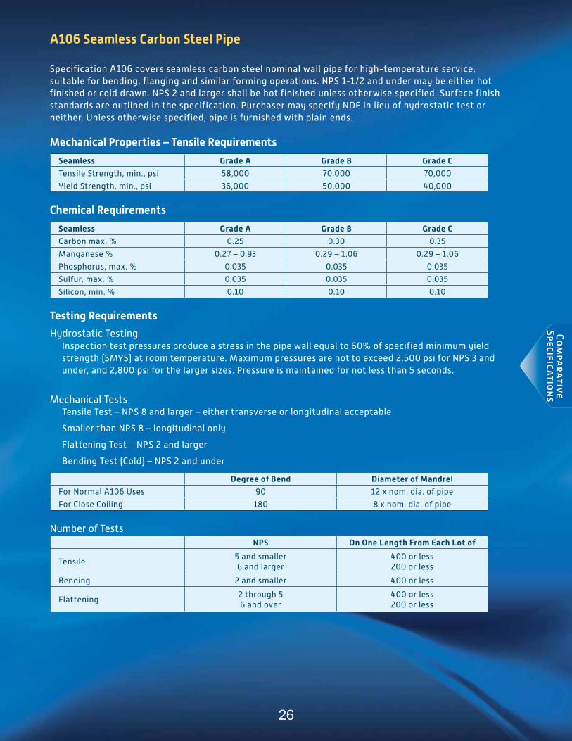
A106 Seamless Carbon Steel Pipe
Specification a106 covers seamless carbon steel nominal wall pipe for high-temperature service, suitable for bending, flanging and similar forming operations. nPS 1-1/2 and under may be either hot finished or cold drawn. nPS 2 and larger shall be hot finished unless otherwise specified. Surface finish standards are outlined in the specification. Purchaser may specify nde in lieu of hydrostatic test or neither. Unless otherwise specified, pipe is furnished with plain ends.
Mechanical Properties – Tensile Requirements
Seamless Grade A Grade B Grade C
tensile Strength, min., psi 58,000 70,000 70,000
Yield Strength, min., psi 36,000 50,000 40,000
Chemical Requirements
Seamless Grade A Grade B Grade C
Carbon max. % 0.25 0.30 0.35
manganese % 0.27 – 0.93 0.29 – 1.06 0.29 – 1.06
Phosphorus, max. % 0.035 0.035 0.035
Sulfur, max. % 0.035 0.035 0.035
Silicon, min. % 0.10 0.10 0.10
Testing Requirements
Hydrostatic testinginspection test pressures produce a stress in the pipe wall equal to 60% of specified minimum yield strength (SmYS) at room temperature. maximum pressures are not to exceed 2,500 psi for nPS 3 and under, and 2,800 psi for the larger sizes. Pressure is maintained for not less than 5 seconds.
mechanical teststensile test – nPS 8 and larger – either transverse or longitudinal acceptable
Smaller than nPS 8 – longitudinal only
Flattening test – nPS 2 and larger
Bending test (Cold) – nPS 2 and under
Degree of Bend Diameter of Mandrel
For normal a106 Uses 90 12 x nom. dia. of pipe
For Close Coiling 180 8 x nom. dia. of pipe
number of testsNPS On One Length From Each Lot of
tensile5 and smaller 6 and larger
400 or less 200 or less
Bending 2 and smaller 400 or less
Flattening2 through 5 6 and over
400 or less 200 or less
Co
mpa
rativ
eS
pecificatio
ns
26

A106 Seamless Carbon Steel Pipe
Permissible Variations
Wall thicknessthe minimum wall thickness at any point shall not be more than 12.5% under the nominal wall thickness specified.
Weights per FootWeight of any individual length shall not vary more than 10% over and 3.5% under that specified. nOte: nPS 4 and smaller – weighed in lots. Larger sizes – weighed by individual length.
Outside diameterOutside diameter shall not vary from standard specified below at any point.
NPS Over Under
1 1/2 and smaller +1/64” -1/64”
2-4 +1/32” -1/32”
5-8 +1/16” -1/32”
10-18 +3/32” -1/32”
20-26 +1/8” -1/32”
Length Requirements
Lengths required shall be specified on order. no “jointers” permitted unless otherwise specified. if no definite lengths required, following practice applies:
Single random – 16’-22’ (5% may be 12’-16’)
double random – minimum length is 22’; minimum average is 35’ (5% may be 16’-22’)
Marking Requirements On Each Length
rolled, Stamped or Stenciled (manufacturer’s option)• manufacturer’s name or brand
• a106 a, a106 B or a106 C
• Hydrostatic test pressure and/or nde, or nH if neither is specified
• Length of pipe
• anSi schedule number or weight class or wall thickness
• Weight per foot (nPS 4 and larger)
• additional “S” if tested to supplementary requirements
Co
mpa
rativ
eS
pecificatio
ns
27

A252 Piling Pipe
Specification a252 covers nominal (average) wall steel pipe piles of cylindrical shape and applies to pipe piles in which the steel cylinder acts as a permanent load-carrying member or as a shell to form case-in-place concrete piles. Surface imperfections exceeding 25% of the nominal wall in depth are considered defects. defects not exceeding 33.5% of the nominal wall in depth may be repaired by welding. Before welding, the defect shall be completely removed.
Mechanical Properties – Tensile Requirements
Grade 1 Grade 2 Grade 3
tensile Strength, min., psi 50,000 60,000 66,000
Yield Strength, min., psi 30,000 35,000 45,000
Chemical Requirements
Phosphorus
Seamless and Welded max % 0.050
Testing Requirements
Hydrostatic testingnone specified
mechanical teststensile test – either longitudinal or transverse at option of manufacturer
number of testsOne tensile property test per 200 lengths
Permissible Variations
Wall thicknessnot more than 12.5% under the nominal wall thickness specified
Weights per Footthe weight of any individual length of pipe shall not vary more than 15% over or 5% under the weight specified. each individual length shall be weighed separately.
Outside diameterShall not vary more than plus or minus 1% from the diameter specified
Lengths
may be ordered in single or double random lengths or in uniform lengths.
Single random – 16’ - 25’ inclusive
double random – Over 25’ with a minimum average of 35’
Uniform – Plus or minus 1” on length specified
Marking Requirements On Each Length
rolled, die Stamped or Paint Stenciled (manufacturer’s option)manufacturer’s name, brand or trademark, heat number, method of pipe manufacture, size, weight, length, wall thickness and aStm a252 and the Grade.
Co
mpa
rativ
eS
pecificatio
ns
28

A501 Hot Formed Carbon Steel Structural Tubing
Specification a501 covers hot-formed, welded and seamless carbon steel square, round, rectangular, or special shape structural tubing for welded, riveted or bolted construction of bridges and buildings, and for general structural purposes. the size range for round is nPS 1/2”-24”.
Mechanical Properties – Tensile Requirements
Grade A Grade B
tensile Strength, min., psi 58,000 70,000
Yield Strength, min., psi 36,000 50,000
elongation in 2 inch min. 23% 23%
Chemical Requirements
Grade A Grade B
Element Heat Analysis Product Analysis Heat Analysis Product Analysis
Carbon, max % 0.26 .30 0.22 (a) 0.26 (a)
manganese, max % no requirement no requirement 1.40 (a) 1.45
Phosphorus, max % 0.035 0.045 0.030 0.040
Sulfur, max % 0.035 0.045 0.020 0.030
Copper (when specified), min % 0.20 0.20 0.20 0.18
a – For each reduction of 0.01 percentage point below the specified maximum for carbon, an increase of 0.06 percentage
point above the specified maximum for manganese is permitted, up to a maximum of 1.50% by heat analysis and 1.60% by
product analysis.
Testing Requirements
Hydrostatic testingnone specified
mechanical teststensile testBend test – on square or rectangular tubing
number of testsOne tension test and one bend test from each lot
Permissible Variations
Wall thicknessnot specified
Weights per footShall not be less than the specified value by more than 3.5%
Outside diameterround tubing
NPS Over Under
1-1/2 and smaller +1/64” -1/32”
2 and larger +1% -1%
Co
mpa
rativ
eS
pecificatio
ns
29

A501 Hot Formed Carbon Steel Structural Tubing
Lengths
Produced in random lengths 16’-22’ or 32’-44’, in multiple lengths and in specific cut lengths
Cut Length Tolerances Over Under
22 feet and smaller +1/2” -1/4”
Over 22 feet +3/4” -1/4”
Marking Requirements On Each Length
rolled, die Stamped, ink Printed or Paint Stenciled (manufacturer’s option)• manufacturer’s name, brand or trademark
• Size and thickness
• aStm a501
Hot-Dipped Galvanizing
When required, weight of zinc shall comply with the requirements in the latest revision of Spec a53, with the additional provision that the manufacturer may determine the coating weight on outside surface only.
Co
mpa
rativ
eS
pecificatio
ns
30

A523 Cable Circuit Piping
Specification a523 covers Seamless and electric resistance Welded steel pipe used as conduit for the installation of high-pressure pipe-type electrical cables. Suitable for welding and for forming operations involving flaring, belling and bending. Size range: nPS 4-12
Mechanical Properties – Tensile Requirements
Seamless and ERW Grade A Grade B
tensile Strength, min., psi 48,000 60,000
Yield Strength, min., psi 30,000 35,000
Chemical Requirements
C max % Mn max % P max % S max %
Heat Product Heat Product Heat Product Heat Product
Grade a SmLS 0.22 0.25 0.90 0.95 0.035 0.045 0.050 0.060
Grade a erW 0.21 0.25 0.90 0.95 0.035 0.045 0.050 0.060
Grade B SmLS 0.27 0.30 1.15 1.20 0.035 0.045 0.050 0.060
Grade B erW 0.26 0.30 1.15 1.20 0.035 0.045 0.050 0.060
Testing Requirements
Hydrostatic testingHydrostatic inspection test pressures are specified. Hydrostatic pressure to be maintained for not less than 5 seconds.
mechanical teststensile test – longitudinal
Weld tensile – transverse
Flattening test – seamless and erW
number of teststensile – one length from each lot of 500 or less
Flattening
Seamless – one length from each lot of 500 or less
erW - Single lengths – crop ends from each length multiple lengths – crop ends from each length plus 2 intermediate rings
Co
mpa
rativ
eS
pecificatio
ns
31

A523 Cable Circuit Piping
Permissible Variations
Wall thicknessminimum wall thickness, at any point, shall not be more than 12.5% under or more than 15.0% over the nominal wall thickness specified.
Weights per FootXS and lighter wall thickness: +5%Heavier than XS wall thickness: +10%
Outside diameterOutside diameter shall not vary more than +1% from specifiedOutside diameter end tolerances (distance of 4” from each end)
NPS Over Under
10 and smaller +1/15” -1/64”
12 +3/32” -1/32”
Lengths
minimum permissible length – 35 ft. 0 in.
maximum permissible length – 50 ft. 0 in.
Marking Requirements on Each Length
roll, Stamp or Paint Stencil (manufacturer’s option)manufacturer’s name or brand, kind of pipe, i.e., Seamless (S) or erW (e); grade, size, weight per foot or wall thickness and aStm a523.
Coatings
Unless otherwise specified, the pipe shall not be given a mill coating of paint, oil or any other material inside or out.
Co
mpa
rativ
eS
pecificatio
ns
32

A618 Hot-Formed High-Strength Low-Alloy Structural Tubing
Specifications a618 covers grades of hot-formed welded and seamless high-strength low-alloy square, rectangular, round or special shape structural tubing for welded, riveted or bolted construction of bridges and buildings and general structural purposes.
Mechanical Properties – Tensile Requirements
Seamless and ERW Grade la & lb Grade II Grade III
tensile Strength, min., psi 70,000 60,000 65,000
Yield Strength, min., psi 50,000 50,000 50,000
Chemical Requirements
Grade la Grade lb Grade II Grade III
Heat Product Heat Product Heat Product Heat Product
Carbon, max. % 0.15 0.18 0.20 - 0.22 0.26 0.23 0.27
manganese % 1.00 max. 1.04 max. 1.35 max. 1.40 max. 0.85-1.25 1.30 max. 1.35 max. 1.40 max.
Phosphorus, max % 0.15 0.16 0.025 0.035 0.025 0.035 0.025 0.035
Sulfur, max. % 0.025 0.045 0.025 0.035 0.025 0.035 0.025 0.035
Silicon, max % - - - - 0.30 0.33 0.30 0.35
Copper, min. % 0.20 0.18 0.20 0.18 0.20 0.18 - -
Vanadium, min. % - - - - 0.02 0.01 0.02 0.01
• Grade la equivalent to USS COr-ten a• Grade lb equivalent to USS COr-ten B• Grade ii equivalent to USS tri-ten• Grade iii equivalent to USS eX-ten 50
Testing Requirements
Hydrostatic testingnot specified
mechanical teststensile (longitudinal) test
Bend test
number of teststwo of each per heat
Co
mpa
rativ
eS
pecificatio
ns
33

A618 Hot-Formed High-Strength Low-Alloy Structural Tubing
Permissible Variations
Wall thicknessnot specified
Weights per Footnot less than the specified weight by more than 3.5%
Outside diameterround tubing
NPS Over Under
1-1/2 and smaller +1/64” -1/32”
2 and larger +1% -1%
Lengths
Produced in random lengths 16’-22’ or 32’-44’, in multiple lengths and in specific cut lengthsCut Length Tolerances Over Under
22 feet and smaller +1/2” -1/4”
Over 22 to 44 feet +3/4” -1/4”
Marking Requirements on Each Length
rolled, die Stamped, ink Printed or Stenciled (manufacturer’s option)• manufacturer’s name, brand or trademark
• Size and wall
• Steel grade
• aStm a618
Co
mpa
rativ
eS
pecificatio
ns
34

API 5L Line Pipe
Specification aPi 5L covers seamless and welded pipe suitable for use in conveying gas, water, oil and other liquefied media.
Chemical Requirements
Specification Grade Cb Mnb P S Si Cr Mo Ni V Cb Ti
aPi 5L44th ed(PSL 1)
Seamless
a25 .21 .60 .030 .030 - - - - - - -
a .22 .90 .030 .030 - - - - - - -
B .28 1.20 .030 .030 - - - - c,d c,d d
X42 .28 1.30 .030 .030 - - - - d d d
X46 .28 1.40 .030 .030 - - - - d d d
X52 .28 1.40 .030 .030 - - - - d d d
X56 .28 1.40 .030 .030 - - - - d d d
X60 .28e 1.40e .030 .030 - - - - f f f
X65 .28e 1.40e .030 .030 - - - - f f f
X70 .28e 1.40e .030 .030 - - - - f f f
aPi 5L44th ed(PSL 1)Welded
a25 .21 .60 .030 .030 - - - - - - -
a .22 .90 .030 .030 - - - - - - -
B .26 1.20 .030 .030 - - - - c,d c,d d
X42 .26 1.30 .030 .030 - - - - d d d
X46 .26 1.40 .030 .030 - - - - d d d
X52 .26 1.40 .030 .030 - - - - d d d
X56 .26 1.40 .030 .030 - - - - d d d
X60 .26e 1.40e .030 .030 - - - - f f f
X65 .26e 1.40e .030 .030 - - - - f f f
X70 .26e 1.65e .030 .030 - - - - f f f
a. .50% max Cu, Ni, Cr and .15 max Mo. For grades up to and including X52, Cu, Cr and Ni shall not be added intentionally. b. For each reduction of .01% below the max C, and increase of .05% Mn is permitted up to a max of 1.65% for grades B, X42 and X52, up to 1.75% for grades >X52
and < X70, and 2.0% for X70. c. Unless otherwise agreed Cb + V < = .15%. d. Cb + V + Ti < = .15%. e. Unless otherwise agreed.f. Unless otherwise agreed the sum of Cb + V + Ti < = .15%.
Specification Grade Cond Cb Mnb P S Si V Cb Ti Other IIW Pcm
aPi 5L44th ed (PSL 2)
(Seamless & Welded)
B r or n .24 1.20 .025 .015 .40 c c .04 e .43 .25
X42 r or n .24 1.20 .025 .015 .40 .06 .05 .04 e .43 .25
X46 n .24 1.40 .025 .015 .40 .07 .05 .04 d, e .43 .25
X52 n .24 1.40 .025 .015 .45 .10 .05 .04 d, e .43 .25
X56 n .24 1.40 .025 .015 .45 .10f .05 .04 d, e .43 .25
X60 n .24f 1.40f .025 .015 .45f .10f .05f .04f d, h as agreed to
aPi 5L44th ed(PSL 2)
(Seamless & Welded)
B Q .18 1.40 .025 .015 .45 .05 .04 .04 e .43 .25
X42 Q .18 1.40 .025 .015 .45 .06 .05 .04 e .43 .25
X46 Q .18 1.40 .025 .015 .45 .07 .05 .04 e .43 .25
X52 Q .18 1.50 .025 .015 .45 .10 .05 .04 e .43 .25
X56 Q .18 1.50 .025 .015 .45 .10 .05 .04 d, e .43 .25
X60 Q .18f 1.70f .025 .015 .45f (V + Cb + ti < = .15) e .4 .25
X65 Q .18f 1.70f .025 .015 .45f (V + Cb + ti < = .15) h .43 .25
X70 Q .18f 1.80f .025 .015 .45f (V + Cb + ti < = .15) h .43 .25
X80 Q .18f 1.90f .025 .015 .45f (V + Cb + ti < = .15) i, j as agreed to
Co
mpa
rativ
eS
pecificatio
ns
35

Specification Grade Cond Cb Mnb P S Si V Cb Ti Other IIW Pcm
aPi 5L44th ed(PSL 2)
(Welded Only)
B m .22 1.20 .025 .015 .45 .05 .05 .04 e .43 .25
X42 m .22 1.30 .025 .015 .45 .05 .05 .04 e .43 .25
X46 m .22 1.30 .025 .015 .45 .05 .05 .04 e .43 .25
X52 m .22 1.40 .025 .015 .45 (V + Cb + ti < = .15) e .43 .25
X56 m .22 1.40 .025 .015 .45 (V + Cb + ti < = .15) e .43 .25
X60 m .12f 1.60f .025 .015 .45f (V + Cb + ti < = .15) h .43 .25
X65 m .12f 1.60f .025 .015 .45f (V + Cb + ti < = .15) h .43 .25
X70 m .12f 1.70f .025 .015 .45f (V + Cb + ti < = .15) h .43 .25
X80 m .12f 1.85f .025 .015 .45f (V + Cb + ti <= .15) i .43 f .25
X90 m .12f 1.85f .025 .015 .45f (V + Cb + ti < = .15) i - .25
X100 m .12f 1.85f .025 .015 .45f (V + Cb + ti < = .15) i, j - .25
X120 m .12f 1.85f .025 .015 .45f (V + Cb + ti < = .15) i, j - .25
b. For Seamless pipe wall thickness > .787” CE shall be by agreement.c. For each reduction of .01% below the max C, and increase of .05% Mn is permitted up to a max of 1.65% for grades B, X42 and X52, up to 1.75% for grades >X52
and < X70, and 2.0% for grades X70 and X80, 2.20 for grade > X80. d. Unless otherwise agreed Cb + V < = .06%.e. Cb + V + Ti < = .15%.f. Unless otherwise agreed, .50% max Cu, .30% max Ni, .30% max CR and .15% max Mo.g. Unless otherwise agreed.h. Unless otherwise agreed the sum of Cb + V + Ti < = .15%.i. Unless otherwise agreed .50% max Cu, Ni, Cr and Mo.j. Unless otherwise agreed .50% max Cu, Cr, Mo and 1.00% max Ni.k. .004% max B.
Tensile Properties – Tensile Requirements Seamless and Welded Pipe
Specification Grade Yield Tensile Y/T Ratio
API 5L 44th ed Min. Max. Min. Max. Max.
PSL-1
a25 25,400 - 45,000 - -
a 30,500 - 48,600 - -
B 35,500 - 60,200 - -
X42 42,100 - 60,200 - -
X46 46,400 - 63,100 - -
X52 52,200 - 66,700 - -
X56 56,600 - 71,100 - -
X60 60,200 - 75,400 - -
X65 65,300 - 77,600 - -
X70 70,300 - 82,700 - -
PSL-2
B 35,500 65,300 60,200 110,200 .93
X42 42,100 71,800 60,200 100,200 .93
X46 46,400 76,100 63,100 110,200 .93
X52 52,200 76,900 66,700 110,200 .93
X56 56,600 79,000 71,100 110,200 .93
X60 60,200 81,900 75,400 110,200 .93
X65 65,300 87,000 77,600 110,200 .93
X70 70,300 92,100 82,700 110,200 .93
X80 80,500 102,300 90,600 119,700 .93
X90 90,600 112,400 100,800 132,700 .95
X100 100,100 121,800 110,200 143,600 .97
X120* 120,400 152,300 132,700 166,100 .99*Only available as dSaW
Co
mpa
rativ
eS
pecificatio
ns
Chemical Requirements (cont)
36

API 5L Line Pipe
Testing Requirements
Hydrostatic testingLists hydrostatic inspection test pressures for all sizes and grades covered by the specification. test pressures are held for not less than:
• Seamless (all sizes) – 5 seconds
• Welded (nPS 18 and smaller) – 5 seconds
(nPS 20 and larger) – 10 seconds
mechanical teststensile test• Seamless – longitudinal• erW – longitudinal and transverse
Charpy tests – PSL 2
Flattening test – erW – all sizes
number of testsFlattening – non-expanded erW for single lengths, crop ends from each length; for multiple lengths, crop ends from first and last pipe of each coil, plus 2 intermediate rings.
tensile –
NPS On One Length From Each Lot of
5 and smaller 400 or less
6 through 12 200 or less
14 and larger 100 or less
Permissible Variations
Wall thicknessSeamless: 0.158”-0.983” wall, tolerance = -12.5 % / +15 %
> = 0.984” wall, tolerance = -0.120” / +0.146” or - /+ 10 % whichever is greater(except if Od is >= 14” & wall is >=.984” then tolerance is -10 /+15%)
HFW: < = 0.197” wall, tolerance = - /+ .020”= 0.198”-0.590” wall, tolerance = - /+ .10.0%”≥ 0.591” wall, tolerance = - /+ .060”
Weights per FootFor Single Lengths Special Plain end and Grade a25 – not more than plus 10% minus 5%
For Single Lengths Other Pipe – not more than plus 10% minus 3.5%
For Carload Lots – not more than minus 1.75%
note: nPS 4 Od and smaller may be weighed individually or in convenient lots; larger sizes by length
Co
mpa
rativ
eS
pecificatio
ns
37

API 5L Line Pipe
Wall, Diameter and Out of Roundness
OD
Diameter Tolerance Out of Round Tolerance
Pipe Body Pipe Ends Pipe Body Pipe Ends
SMLS Welded SMLS Welded SMLS Welded SMLS Welded
< 2.375 - 0.031 / + 0.016 - 0.016 / + 0.063 included in the diameter tolerance
2.375 - 6.625 -/+ 0.0075 (d) - 0.016 / + 0.063 020 (d) 0.015 (d)
> 6.625 - 24.00 -/+ 0.0075 (d)-/+ 0.007 5 (d) up to -/+ 0.125
-/+ 0.005 (d) up to -/+ 0.063”
020 (d) 0.015 (d)
Lengths
Plain End PipeShortest Length
in Entire ShipmentMinimum Avg. Length
in Entire ShipmentMaximum Length
20’ nominal 9’0” 17’6” 22’6”
40’ nominal 14’0” 35’0” 45’0”
60’ nominal 21’0” 52’6” 65’0”
80’ nominal 28’0” 70’0” 85’0”
Marking Requirements on Each Length
Paint Stenciled or die Stamped manufacturer’s name or mark, Spec 5L, size, weight per foot, grade, process of manufacture, type of steel, length (nPS 4 and larger only). test pressure when higher than tabulated (nPS 2 and larger only).
Supplemental Annexes
aPi Specification 5L contains 15 Supplemental annexes that address special conditions and/or additional requirements.
annex a Specification for welded jointers annex B manufacturing procedure qualification for PSL 2 pipeannex C treatment of surface imperfections and defectsannex d repair welding procedure annex e non-destructive inspection for other than sour service or offshore serviceannex F requirements for couplings (PSL 1 only)annex G PSL 2 pipe with resistance to ductile fracture propagationannex H PSL 2 pipe ordered for sour serviceannex i Pipe ordered as “through the Flowline” (tFL) pipeannex J PSL 2 pipe ordered for offshore serviceannex K non-destructive inspection for pipe ordered for sour service and/or offshore service annex L Steel designations annex m Correspondence of terminology between iSO 3183 and its source documentsannex n identification/explanation of deviations annex O aPi monogram
Co
mpa
rativ
eS
pecificatio
ns
38

API 5L Line Pipe
API Specification 5L PSL 1 and PSL 2 Comparison
Summary of Differences Between PSL1 and PSL2
Parameter PSL 1 PSL 2 Reference
Grade Range L175 or A25 through L485 or X70 L245 or B through L830 or X120 Table 1 Table 2
Grade Suffix — R, N, Q or M Table 2 Footnote b
Type of Pipe Ends Plain End, Belled End, Threaded , Special Coupling Pipe End
Plain End Only < = 0.125”t Square Cut
>0.125” 30° Bevel Unless Otherwise Agreed
Table 2, 9.12.1.2 9.12.5, 9.12.5.3
Manufacturing Routes Not Defined in Detail Defined in Detail Table 3
Manufacturing Procedure Qualification — If Agreed 7.2 c) 40) Annex B
Resistance to Ductile Fracture — If Agreed 7.2 c) 49) Annex G
For Sour Service — If Agreed 7.2 c) 50) Annex H
Offshore Pipe — If Agreed 7.2 c) 54) Annex J
Steel Making — Killed, Fine Grain Practice 8.3.2
Heat Treatment of Weld Seam and the HAZ of HFW Pipe
Simulate Normalizing OR by Agreement Other Methods
Heat Treated so as to Simulate Normalizing 8.8.1 - 8.8.2
Chemical Traceability of Heat Identity
Traceable Only Until All Related Chemical Tests are Performed and
Conformance is Shown
Each Length of Pipe Must be Traceable Even After Completion of all Related
Chemical Tests and Conformance is Shown8.13.1 - 8.13.2
Physical Properties Traceability of Unit Identity
Traceable Only Until All Related Mechanical Tests are Performed and
Conformance is Shown
Each Length of Pipe Must be Traceable Even After Completion of all Related
Mechanical Tests and Conformance is Shown8.13.1 - 8.13.2
Max C Seamless Pipe N 0.28% for Grades B - X60 0.24% for Grades B - X60 9.2.2, Table 4 & 5
Max C Seamless Pipe Q 0.28% for Grades B - X60 0.18% for Grades B - X60 Table 4 & 5
Max C Welded Pipe M 0.26% for Grades B - X70 0.22% for Grades B - X56 0.12% for Grades 60 - X70 Table 4 & 5
Max Si Seamless Pipe R — 0.40% for Grades B - X46 0.45% for Grades 52 - X70 Table 4 & 5
Max Si Welded Pipe M — 0.45% for Grades B - X70 Table 4 & 5
Max Mn Seamless Pipe R 1.30% for Grade X42 1.20% for Grade X42 Table 4 & 5
Max Mn Seamless Pipe N 1.30% for Grade X42 1.20% for Grade X42 Table 4 & 5
Max Mn Seamless Pipe Q1.20% for Grade B
1.30% for Grade X421.40% for Grades X46 - X70
1.40% for Grades B - X421.50% for Grades X52 - X561.70% for Grades X60 - X70
Table 4 & 5
Max Mn Welded Pipe M
1.40% for Grade X421.40% for Grade X601.45% for Grade X651.45% for Grade X70
1.30% for Grade X421.60% for Grade X601.60% for Grade X651.70% for Grade X70
Table 4 & 5
Max P Seamless Pipe 0.030% for Grade B - X70 0.025% for Grade B - X70 Table 4 & 5
Max P Welded Pipe 0.030% for Grade B - X70 0.025% for Grade B - X70 Table 4 & 5
Max S Seamless Pipe 0.030% for Grade B - X70 0.015% for Grade B - X70 Table 4 & 5
Max S Welded Pipe 0.030% for Grade B - X70 0.015% for Grade B - X70 Table 4 & 5
Max V Seamless Pipe N —0.06% for Grade X420.07% for Grade X46
0.10% for Grade X52 - X60Table 4 & 5
Max V Seamless Pipe Q — 0.05% for Grades B - X520.07% for Grades X56 Table 4 & 5
Max V Welded Pipe M — 0.05% for Grades B - X46 Table 4 & 5
Max Nb Seamless Pipe N — 0.05% for Grades X42 - X60 Table 4 & 5
Max Nb Seamless Pipe Q — 0.05% for Grades B - X56 Table 4 & 5
Max Nb Welded Pipe M — 0.05% for Grades B - X46 Table 4 & 5
Max Ti Seamless Pipe N — 0.05% for Grades B - X60 Table 4 & 5
Max Ti Seamless Pipe Q — 0.04% for Grades B - X56 Table 4 & 5
Max Ti Welded Pipe M — 0.04% for Grades B - X46 Table 4 & 5
Co
mpa
rativ
eS
pecificatio
ns
39

ITT Standard Pipe and Line Pipe
Summary of Miscellaneous Pipe Specifications
aStm a135two grades (a and B) of erW pipe in nPS 3/4 to 30 with wall thickness of 0.500”. the pipe is intended for conveying gas, vapor, water or other liquid.
aStm a333 nine grades of minimum wall thickness seamless and erW pipe for use at low temperatures.
aStm a513erW carbon and alloy mechanical tubing in a variety of grades and sizes from nPS 1/2 to 15 in walls to 0.650”.
aStm a519Several grades of carbon and alloy steel seamless mechanical tubing in sizes to nPS 12 and under.
aStm a589Four types of plain end or threaded and coupled carbon steel seamless or erW pipe for use as water well casing.
CSa Z245.1Canadian steel pipe specification for seamless and erW pipe that is somewhat equivalent to the aPi 5L Line Pipe Specification.
Co
mpa
rativ
eS
pecificatio
ns
Carbon Equivalent CE — Maximum CE Required for Each Grade Table 4 & 5
Low Frequency Welding LFW <70 kHz Acceptable Process Not an Acceptable Process Table 2
Laser Welding LW Acceptable Process Not an Acceptable Process Table 2
Yield Strength, Maximum — Maximum Required for Each Grade Table 6 & 7
UTS, Maximum — Maximum Required for Each Grade Table 6 & 7
Yield to Tensile Ratio Maximum — Maximum Required for Each Grade Table 6 & 7
CVN Impact Toughness — Testing Procedures and Minimum Requirements for Each Grade 9.8, Table 8, Table 22
Drop Weight Tear Test DWT — By Agreement (D>=20”) 7.2 c) 12), 9.9, Table 18
Inspection Document in Accordance with ISO 10474:1991 or EN 10204:2004 If Agreed Mandatory 10.1.2
Non-destructive Inspection Full Length (100%), as Given in Table E.2
Grade L245 or B Quenched and Tempered SMLS Pipe and Other SMLA Grades if Agreed All SMLS Pipe E.3.1.2
API 5L Line Pipe
API Specification 5L PSL 1 and PSL 2 Comparison (cont)
40

Standard PiPe & Line PiPe taBLeSmill hydrostatic test pressure data was calculated on
the basis of a fiber stress equal to a percentage of the
specified minimum yield strength for the various sizes
and grades. For specific information, aStm standards
and/or aPi Specification 5L should be consulted. due
to limited pump capacity, maximum hydrostatic test
pressures for 22”, 24” and 26” Od seamless pipe are
2,700, 2,300 and 2,000 psi respectively. Some outside
diameters, walls and grades are listed for information
only and are not necessarily regular production items.
the tables do not represent the full manufacturing
capacity. Sizes, walls and grades not listed are subject
to inquiry.
1 as noted throughout the Line Pipe tables, these grades are available in seamless only.
Pipe Ta
bles
41

MEDIUM & HEAMEDIUM & HEAVY PIPEVY PIPE
250 MPaMinimum Yield Strength Minimum Tensile Strength 320 MPa
Minimum Elongation in 5.65√So 22%
TOLERANCESStraightness Thickness Tolerance Dimensional Tolerance Length Tolerance +50mm/-0mm
If tighter tolerances are required, they must be specified at the time of order (conditions apply).
SUPPLY CONDITIONS - PAINTED FINISHRed (Normal finish) or black (clear).
The coating thicknesses for these paints are:
Red & Black 12 microns average.
Note: Non-standard finishes, such as NOPC, are available if ordered prior to rollings. Conditions apply.
GALVANISED FINISHHot dipped galvanised pipe is manufactured and tested to meet the requirements of AS 4792.
Coating mass: 300 g/m2 min average both sides.
The coating adherence of the galvanising is satisfactory for the pipe to be bent to a radius 6 times the diameter of the pipe.
STANDARD LENGTHS(DN 20 - DN 150) Red/Black/Galvanised 6.5mNote: DN stands for Nominal Size and replaces NB (Nominal Bore).
THICKNESS AND MARKINGGrade C250 pipe is available in medium (M) and heavy (H) wall thickness. These thicknesses are identified by thefollowing end colour codes:
Medium (M) BlueHeavy (H) Red
GRADE C250
MANUFACTURING PROCESSGrade C250 Pipe, for general mechanical and low pressure reticulation applications, is manufactured by cold-forming and high frequency Electric Resistance Welding. The cold-forming process enhances the strength, hardness and surface finish of the pipe and produces product to tight dimensional tolerances. Pipe is tested by using non-destructive Eddy Current methods during the process.
AUSTRALIAN STANDARDSGrade C250 Pipe is manufactured and tested to comply with the requirements of the following specifications:
AS 1074 - Steel tubes and tubulars for ordinary service.
AS 1163 - Structural steel hollow sections(Grade C250, C250LO).
AS 4792 - Hot-dipped galvanised coating on ferrous hollow sections. Applied by a continuous or a specialised process.
LO indicates grades with guaranteed impact performances at 0˚C. With impact guaranteed properties, the opportunities for the designer are now enhanced in low temperature service environments under AS 4100.
MECHANICAL PROPERTIES
Refer toAustralianStandards}
Pipe Ta
bles
42

MEDIUM & HEAMEDIUM & HEAVY PIPEVY PIPE
WORKING PRESSURES – THREADED JOINTS TAPER/PARALLEL THREAD
Nominal
SizeDN Medium Heavy Med. &
HeavyMedium
Press. Temp.Heavy
Press. Temp.Medium
Press. Temp.Heavy
Press. Temp.
TYPE OF SERVICE
Water & Inert Oil L.P.G. Fuel OilOther Applications
(Including Steam & Compressed Air)
(mm) kPa kPa kPa kPa ºC kPa ºC kPa ºC kPa ºC
15 2070 2410 140 1030 100 1210 192 1210 100 1210 19220 2070 2410 140 1030 100 1210 192 1210 100 1210 19225 2070 2410 140 1030 100 1210 192 1210 100 1210 19232 1720 2070 140 1030 100 1030 192 1030 100 1030 19240 1720 2070 140 1030 100 1030 192 1030 100 1030 19250 1380 1720 140 860 100 860 192 860 100 860 19265 1380 1720 – 860 100 860 192 860 100 860 19280 1380 1720 – 860 100 860 192 860 100 860 192100 1030 1380 – 690 100 850 192 690 100 690 192125 1030 1380 – – – – – – – – –150 860 1030 – – – – – – – – –
Grade C250 MASS AND BUNDLING DATA - Calculated in accordance with AS 1163
13.5 x 2.3 8 M Supplied in 400 2320 0.64 0.67 1560 1490 1.49 1.552.9 8 H Circular Bundles 400 2320 0.77 0.79 1310 1260 1.78 1.84
17.2 x 2.3 10 M Supplied in 300 1950 0.84 0.88 1190 1140 1.64 1.712.9 10 H Circular Bundles 300 1950 1.02 1.05 985 951 1.98 2.05
21.3 x 2.6 15 M 364 318 217 1410.5 1.21 1.25 830 798 1.70 1.773.2 15 H 364 318 217 1410.5 1.44 1.48 695 674 2.03 2.09
26.9 x 2.6 20 M 350 306 127 825.5 1.56 1.60 642 623 1.29 1.323.2 20 H 350 306 127 825.5 1.87 1.92 535 522 1.54 1.58
33.7 x 3.2 25 M 327 327 91 591.5 2.41 2.46 415 406 1.42 1.464.0 25 H 327 327 91 591.5 2.93 2.99 341 335 1.73 1.77
42.4 x 3.2 32 M 383 337 61 396.5 3.09 3.17 323 316 1.23 1.264.0 32 H 383 337 61 396.5 3.79 3.86 264 259 1.50 1.53
48.3 x 3.2 40 M 436 384 61 396.5 3.56 3.64 281 274 1.41 1.444.0 40 H 436 384 61 396.5 4.37 4.45 229 225 1.73 1.77
60.3 x 3.6 50 M 422 374 37 240.5 5.03 5.14 199 195 1.21 1.244.5 50 H 422 374 37 240.5 6.19 6.30 161 159 1.49 1.51
76.1 x 3.6 65 M 533 472 37 240.5 6.44 6.57 155 152 1.55 1.584.5 65 H 533 472 37 240.5 7.95 8.08 126 124 1.91 1.94
88.9 x 4.0 80 M 445 397 19 123.5 8.38 8.54 119 117 1.03 1.054.9 80 H 445 397 19 123.5 10.3 10.6 99 97 1.25 1.27
101.6 x 4.0 90 M 508 454 19 123.5 9.63 9.81 104 102 1.19 1.214.9 90 H 508 454 19 123.5 11.9 12.2 86 84 1.44 1.47
114.3 x 4.5 100 M 571 509 19 123.5 12.2 12.4 82 81 1.50 1.535.4 100 H 571 509 19 123.5 14.50 14.7 69 68 1.79 1.82
139.7 x 5.0 125 M 699 382 13 84.5 16.6 16.9 60 59 1.40 1.425.4 125 H 699 382 13 84.5 17.9 18.1 56 55 1.51 1.53
165.1 x 5.0 150 M 660 451 10 65 19.7 20.0 51 50 1.28 1.305.4 150 H 660 451 10 65 21.3 21.6 47 46 1.38 1.40
Notes: 1. M= Medium, H= Heavy
DIMENSIONSDesignation
do t
mm mm mm W x H 6.5 m m
NominalSizeDN
BundleDimensions
mm
LengthsPer
Bundle
MetresPer
Bundle
BUNDLING MASSNominal Mass
kg/mBlack Galv. Black Galv. Black Galv.
m/tonne tonnesMass Per Bundle
WORKING PRESSURES –WELDED JOINTSWhere AS 1074 pipe is used in pressure piping covered by AS 4041, the maximum pressure shall not exceed 1210 kPa for AS 1074 pipe up to and including DN 100 and 1030 kPa for AS 1074 pipe exceeding DN 100.
THREADED PIPEScrewed on one or both ends in accordance with AS 1074.
The tapered Whitworth thread used complies with the requirements of AS 1722, Part 1 and is suitable for both parallel and taper threaded sockets.
END PROCESSING OPTIONS• Plain End• Shouldered• Roll Grooved• Threaded
Pipe Ta
bles
43

LIGHT AND EXTRA LIGHT PIPELIGHT AND EXTRA LIGHT PIPE
Grade C350 MASS AND BUNDLING DATA - Calculated in accordance with AS 1163
350 MPaMinimum Yield Strength Minimum Tensile Strength 450 MPa
Minimum Elongation in 5.65√So 20%
SUPPLY CONDITIONSSurface Finish Black/Painted/GalvanisedStraightness Thickness Tolerance Dimension Tolerance
Standard Length 6.5mLength Tolerance +50mm/-0mm
GALVANISINGGrade C350 pipe is manufactured and tested to meet the requirements of AS 4792 Galvanised coatings.
Coating Mass: 300g/m2 min average both sides.
The coating adherence of the galvanising is satisfactory for the pipe to be bent to a radius 6 times the diameter of the pipe.
WELDINGThe following consumables are recommended by AS 1554.1 when welding C350 sections.
Manual metal-arc (MMAW) E41XX, E48XX
Gas metal-arc (MIG) (GMAW) W50X
mm mm26.9 x 2.0
2.3
33.7 x 2.0
2.6
42.4 x 2.0
2.6
48.3 x 2.3
2.9
60.3 x 2.3
2.9
76.1 x 2.3
3.2
88.9 x 2.6
3.2
101.6 x 2.6
3.2
114.3 x 3.2
3.6
139.7 x 3.0
3.5
165.1 x 3.0
3.5
mm20 XL20 LT25 XL25 LT32 XL32 LT40 XL40 LT50 XL50 LT65 XL65 LT80 XL80 LT90 XL90 LT
100 XL100 LT125 XL125 LT150 XL150 LT
W350350327327383383436436422422533533445445508508571571699699660660
H306306327327337337384384374374472472397397454454509509382382451451
6.5 m1271279191616161613737373719191919191913131010
m825.5825.5591.5591.5396.5396.5396.5396.5240.5240.5240.5240.5123.5123.5123.5123.5123.5123.584.584.56565
Black1.2281.3951.5641.9941.9932.5522.6093.2473.2904.1054.1865.7535.5346.7636.3487.7658.7689.828
10.11411.75611.99313.949
Galv.1.2751.4421.6232.0532.0692.6272.6963.3333.3994.2134.3255.8905.6966.9256.5347.9518.977
10.03710.37112.01312.29814.253
Black81471764050150239238330830424423917418114815812911410299858372
Galv.78469461648748338137130029423723117017614415312611110096838170
Black1.0141.1520.9251.1800.7901.0121.0351.2870.7910.9871.0071.3840.6830.8350.7840.9591.0831.2140.8550.9930.7800.907
Galv.1.0531.1900.9601.2140.8201.0421.0691.3210.8181.0131.0401.4170.7030.8550.8070.9821.1091.2400.8761.0150.7990.926
DIMENSIONSDesignationdo t
NominalSize DN
Bundle Dimensions mm
LengthsPer Bundle
MetresPer Bundle
Nominal Masskg/m m/tonne tonnes
Mass Per BundleBUNDLING MASS
x
Notes: 1. LT= Light, XL= Extra Light. End colour codes. Light (LT) Yellow, Extra Light (XL) Green.
GRADE C350
Grade C350 Pipe is a lightweight, high strength pipe for general mechanical and structural applications. It is manufactured by cold forming and high frequency electric resistance welding.
C350 is available in black, painted and galvanised finishes. Also available with one or both ends swaged in sizes from 25 NB to 50 NB.
SPECIFICATIONSManufactured and tested to meet the requirements of the following specifications:
AS 1163 Structural Steel Hollow Sections (Grade C350, C350L0).
AS 4792 Hot-dipped galvanised coating on ferrous hollow sections. Applied by a continuous or a specialised process.
MECHANICAL PROPERTIES
Refer toAustralianStandards
}
Pipe Ta
bles
44

APPLICAAPPLICATION GUIDETION GUIDE
COMMERCIAL PIPE APPLICATION GUIDE – TYPICAL PIPING SYSTEM MAKEUP
COMMERCIAL BLACK PAINTED
The flanges and fittings listed in these charts are all available from ITT Grinnell Piping Systems and are described in our “Pipe Fittings” and “Stainless Steel” catalogues.
Notes: The jointing methods and fittings listed above are typical of those selected by our customers when ordering Australian Standard steel pipe for reticulation (non-structural) use. Reference should be made to relevant piping codes and standards when selecting products or materials for specific applications. These charts are offered as a guide only and does not represent or replace any of the official piping codes or standards.
PIPE GRADE
Grooved or Shouldered Fittings
Medium
Heavy
Extra Heavy Buttweld, Flanged Buttweld Fittings, Flanges, Socket-Weld Fittings
TYPICAL JOINTING METHODS TYPICAL COMPLEMENTARY FITTINGS
COMMERCIAL GALVANISED
PIPE GRADE
Light & Extra Light Roll Grooved, Shouldered Grooved or Shouldered Fittings
Medium Roll Grooved, Shouldered, Threaded
Shouldered Fittings, Galvanised Steel Screwed Fittings, Screwed Flanges
TYPICAL JOINTING METHODS TYPICAL COMPLEMENTARY FITTINGS
LINEPIPE, CARBON AND STAINLESS STEEL
PIPE GRADE
Various Wall Thicknesses and Schedules
TYPICAL JOINTING METHODS TYPICAL COMPLEMENTARY FITTINGS
Light & Extra Light Buttweld, Flanged, Roll Grooved, Shouldered
Flanges, Roll
Roll
Roll Grooved or Shouldered Fittings Galvanised Malleable or Galvanised Steel Screwed Fittings, Screwed Flanges
Heavy Shouldered, Threaded
Buttweld Fittings, O’let Fittings Socketweld Fittings & O’lets ANSI & Australian Flanges NPT & BSP Fittings, O’lets Roll Grooved System Shouldered System
Buttwelding Socket Welding Flanged Threaded Grooved Shouldered
Buttweld, Flanged, Roll Grooved, Shouldered, Threaded
Buttweld Fittings, Flanges, Roll Grooved or Shouldered Fittings, Black or Galvanised Screwed Fittings (Malleable Iron or Steel)
Buttweld, Flanged, Cut Grooved Shouldered, Threaded
Buttweld Fittings, Flanges, Roll Grooved or Shouldered Fittings, Black or Galvanised Steel Screwed Fittings
Pipe Ta
bles
45

LINEPIPELINEPIPE
OneSteel is Australia’s largest stockist of seamless and welded pipes in both carbon
and alloy steel.
These pipes are used in a diverse range of fluid handling and structural
applications from Petroleum and Chemical Processing to the Mining and allied
industries. The general stock range for seamless and welded carbon steel pipes is
8mm to 600mm nominal diameter.
ASME B36.10. WELDED AND SEAMLESS WROUGHT STEEL PIPEASME B36.10 covers the standardization of dimensions of welded and seamless wrought steel pipe. It shows both imperial and metric units, the metric units being soft conversions of the imperial units.
On pages 12 and 13 we have shown only metric dimensions to ASME B36.10 for the more popular size range. We have also included inside diameter (I.D.) and metric nominal size (DN) which are not shown in ASME B36.10.
1. NOMINAL SIZE – May be expressed in S.I. metric (mm) or imperial (inch) units.
2. OUTSIDE DIAMETER – is shown to the nearest 0.1mm for outside diameters which are 406.4mm O.D. andsmaller, and to the nearest 1.0mm for outside diameters larger than 406.4mm O.D. We have shown the equivalentinch size underneath in brackets – ( ).
3. WALL THICKNESS – is shown rounded to the nearest 0.01mm.
4. INSIDE DIAMETER – is not shown in ASME B36.10, however, by using the inch measurements in ASME B36.10,we have calculated the inside diameter (I.D.) in inches and used the factor 25.4 to convert to millimetres to the nearest0.1mm
5. MASS (WEIGHT) – is shown in kilograms per meter (kg/m) for plain end pipes. These are calculated valuesusing the formula shown at the bottom of page 13 (taken from B36.10).
6. WALL THICKNESS DESIGNATIONS – The wall thickness designations “Standard WT”, “Extra Strong” and“Double Extra-Strong”, have been commercially used designations for many years. Schedule numbers were added asa convenient designation for use in ordering pipe. Standard WT and Schedule 40 are identical for sizes up to NPS 10inclusive. All larger sizes of Standard WT have 9.53mm wall thickness. Extra-Strong and Schedule 80 are identical forsizes up to NPS 8 inclusive. All larger sizes of Extra-Strong have 12.70mm wall thickness.
7. PIPE ENDS – Unless otherwise specified pipe ends are normally supplied as below:-
(a) Up to and including 48.3mm O.D. size are supplied with plain ends cut square.
(b) Above 48.3mm O.D. sizes (except for Double Extra-Strong pipe) are supplied with plain ends bevelled.
(c) All Double Extra-Strong pipe is supplied with plain ends cut square.
8. END PREPARATION(a) Bevelled ends for API steel linepipe are normally to API specification i.e. Angle 30˚-0˚
+5˚
(b) Bevelled ends for steel pipe to ASTM specifications are normally to ASME B16.25 i.e. Angle 30˚-0˚+5˚
METRIC CONVERSION TERMINOLOGYSoft conversion is an exact mathematical equivalent using known conversion factors from imperial to metric. eg. Inch to millimetres (mm) = 1 x 25.4. Therefore 123/4 inch x 25.4 = 323.85mm.Soft conversion can only be applied to actual measurement, it cannot be applied to nominal sizes.
Hard conversion is where pipe manufactured to imperial sizes (O.D. x WT in actual inches) is replaced by pipe manufactured to metric sizes (O.D. x WT in actual millimetres [mm] ).
Pipe is only quoted as a typical material example.
Pipe Ta
bles
46

METHODS OF MANUFMETHODS OF MANUFAACTURECTURE
SEAMLESS PIPEIn the seamless pipe-making process tube rounds are heated in a furnace, after which they are pierced, then rolled by the Mandrel or Plug-Mill process into pipes and tubes of specified diameters and wall thicknesses.
Seamless tubular products are generally hot-rolled, but can also be supplied cold-drawn (up to 273mm O.D.) when required.
The “Push-Bench” process can also be used in the manufacture of seamless pipe. In this process, a steel billet is furnace heated to the plastic state and partly punched at one end to take a mandrel. The billet is then forced by the mandrel through a series of gradually reducing dies, until the required outside diameter has been attained, the I.D. being determined by the size of the mandrel.
Steel plates are first U-shaped then O-formed by a hydraulic press. The seam is welded from inside and outside automatically by the submerged-arc process. Hydraulic expansion gives the pipe precise diameter and roundness and relieves residual stresses caused by forming and welding.
ELECTRIC-RESISTANCE WELDED PIPE (E.R.W.)In Australia, as in modern installations overseas, ERW Linepipe has gained increased acceptance, where Seamless Pipe was once considered essential, because of its uniform quality and dimensions, and its cost advantage.
The ERW manufacturing process is described below:
At the pipe mill the strip is uncoiled, levelled and crop-sheared. It is then trimmed on both sides simultaneously to correct width and immediately fed into the forming and welding line. During the process, the strip is closely checked for surface defects.
A series of cold forming rolls changes the strip progressively into tubular form with abutting edges on top. The longitudinal edges are joined by high frequency electric resistance welding. The weld is then heat treated electrically. Special devices remove inside and outside flash from the weld to give uniform wall thickness of the pipe.
SPECIFICATIONSAPI 5L 5LXASTM A53
ASTM A106ASTM A333ASTM A335
SIZESUP TO 762mm O.D.
SPECIFICATIONSAPI 5L & 5LXASTM A53, A135, ASTM A252, A333
SIZESUP TO 610mm O.D.
SPECIFICATIONSAPI 5L 5LX & 5LU ASTM A53
SIZESUP TO 1820mm O.D.
The welded part is then heat-treated by post annealing to ensure adequate ductility at the weld and adjacent zone. The pipe is passed through a series of cold sizing rolls to progressively reduce the diameter to accurate size. This operation also increases strength and improves surface condition.
The pipe is then cut to specified length by a flying cut-off machine. After the straightening operation, ends of the pipe are cropped, then squared or bevelled depending on end finish requirements. The pipe is then hydrostatically tested to specified pressure. Also test specimens are taken during the process to check chemical and mechanical properties.
Each length of pipe is inspected by the ultrasonic method on the weld and checked as to diameter, wall thickness, surfaces, end finish, camber and concentricity. The length and weight of pipe is measured and recorded and protective coating is applied on the outside surface.
U.O.E. DOUBLE SUBMERGED ARC WELDED PIPE
Pipe Ta
bles
47

MAMATERIAL SPECIFICATERIAL SPECIFICATIONS FOR PIPING COMPONENTSTIONS FOR PIPING COMPONENTS
PIPING COMPONENT SPECIFICATIONS
This page shows comparable ASTM and API specifications for the basic components of welded piping systems. Specification numbers and material grades are shown; for example, ASTM specification A106 Grade B is indicated in the table as A106-B. Other specifications exist and may be required for special piping systems. Materials shown are those most frequently used today.
Also tabulated are the permissible raw material specifications which are used in the manufacture of welding fittings. Selection from these is at the discretion of the fitting manufacturer.
* When fittings are of welded construction, the fitting manufacturer shall supplement the grade symbol marking with the letter “W”.
§ No ASTM specification has been written. The welding fitting grade symbol is that recommended by MSS Standard SP-25, and the raw materials shown arethose commonly used.
II The numerals in these grade symbols are the first two numbers of the minimum guaranteed yield strength of the fittings. Fittings having other minimum yield strengths may be similarly designated by using the applicable numerals.
A53-BA106-BA135-BA139-B A234-WPB A105 A106-B A105API-5L-B
A106-C A234-WPC A105 A106-C
A333-6 A420-WPL6 A350-LF2 A333-6 A350-LF2
A381-35 Grade WPY35 § II A105 A106-B A105
API-5LX-X42, Grade WPY42 § II A182-F1 A381-42 182-F1X46, X52 Grade WPY52 § II - A381-52 -
A155-CM70
A335-P1A369-FP1A155-1/2CRA335-P2 Grade WP2 § A182-F2 A335-P2 A182-F2A369-FP2A155-1CRA335-P12 A234-WP12 A182-F12 A335-P12 A182-F12A369-FP12A155-11/4CRA335-P11 A234-WP11 A182-F11 A335-P11 A182-F11A369-FP11A155-21/4CRA335-P22 A234-WP22 A182-F22 A335-P22 A182-F22A369-FP22A155-5CRA335-P5 A234-WP5 A182-F5 A335-P5 A182-F5A369-FP5A335-P7A369-FP7A335-P9A369-FP9
A333-3 A420-WPL3 A350-LF3 A333-3 A350-LF3
A333-9 A420-WPL9 A350-LF9 A333-9 A350-LF9
Grade B
Grade C
LowTemperature
HighYield
1/2 Mo
1/2Cr-1/2Mo
1Cr-1/2Mo
11/4Cr-1/2Mo
21/4Cr-1Mo
5Cr-1/2Mo
7Cr-1/2Mo
9Cr-1Mo
31/2Ni
Cu-NiLow Alloy Steel
MATERIAL
Carbon Steel
CarbonMoly-Steel
Low TempFerritic Steel
ChromeMoly-Steel
PIPING COMPONENTS
Pipe Welding Fittings * Flanges Pipe Forgings
RAW MATERIAL FORWELDING FITTINGS
A234-WP1 A182-F1 A335-P1 A182-F1
Grade WP7 A182-F7 A335-P7 A182-F7
Grade WP9 A182-F9 A335-P9 A182-F9
Pipe Ta
bles
48

Pipe Ta
bles
49
Tolerances (Excerpts from API Specifications)
Tensile and Chemical Requirements (Excerpts from API Specifications, 1983 edition)
Tensile Reguirements
Application Grade Yield Strength Tensile Strength Elongation
psi MPa kg/mm2 psi MPa kg/mm2
% minmin min min min min min
API SL Grade A 30,000 207 21.1 48,000 331 33.7
API SL Grade B 35,000 241 24.6 60,000 413 42.2
API SL Grade X42 42,000 289 29.5 60,000 413 42.2
API SL Grade X46 46,000 317 32.3 63,000 434 44.3
API SL Grade X52 52,000 358 36.6 46.4 (1) 66,000 *1
(2)
(1) 455
(2) 496 50.6 e =
Line Pipe *2
API SL Grade X56 *6 56,000 386 39.2
49.9 0.2 (1)
72,000
71,000 *1(2) 75,000
(1) 489
(2) 517 52.7 625,000 A
API SL * 52.7
u0.9Grade X60 •3
6 (1) 75,000 *1
60,000 413 42.2 (2) 78,000
(1) 517
(2) 537 54.8
*6 54.1 API SL Grade X65 *8 65,000 448 45.7 (1) 77,000 *1
(2) 80,000
(1) 530
(2) 551 56.2 *11
API SL Grade X70 *6
70,000 482 49.2 82,000 565 57.6 *11
API SLU Grade X80 80,000
API SLU Grade X100 100,000
*1 (1) Wall thickness > 0.375in., O . Any wall thickness, OD D< .:2020i in. n
(2) Wall thickness :;; 0.375in., OD .: 20in.
551
689
*2 The minimum elongation in 2 inches (60.8 mm) shall be determined by the following formula:
A 0.2e = 625,000 --
U 0.9 where: e =
A =
U =
minimum elongation in 2 inches (50.80 mm) in per cent rounded to the nearest 1 /2 per cent.
cross sectional area of the tensile test specimen in square inches, based on specified outside diameter or nominal specimen width and specified wall thickness rounded to the nearest 0.01 sq. in., or 0.75 sq. in., whichever is smaller.
specified tensile strength, psi.
*456.2 95,000/125,000 655/862 66.8/87.8
*470.3 110,000/135,000 758/931 77.3/94.9
*3 The minimum tensile strength for grade X60 electricresistance welded pipe in all sizes and wall thick-nesses shall be 75,000 psi (52.7 kg/mm2).
*4 Tensile strength means min. value/max. value
*5 Figures in parentheses are values for seamless pipe. Upperline value means non-expanded, Lowerline value means coldexpanded. In grades X42 through X65, for each reduction of 0.01 per cent below the maximum carbon content, an increase of 0.05 per cent manganese above the specified maximum is permissible, up to a maximum of 1.45 per cent for X52 and lower and up to a maximum of 1.60 per cent for grades higher than X52.
*6 Other chemical analyses may be furnished by agreement between purchaser and manufacturer.
*7 Either columbium, vanadium, titanium, or a combinationthereof, shall be used at the discretion of the manufacturer.

Tolerances (Excerpts from API Specifications)
Chemical Requirements for Ladle Analyses, %
C *5 Si Mn •5 p s Cb V Ti
max max max max max min min min
0.21 (0.22) 0.90 0.04 0.05
0.26 (0.27) 1.15 0.04 0.05
*13 0.28 (0.29) 1.25 0.04 0.05
0.30 (0.31) *13 1.35 0.04 0.05 0.28 (0.29) 1.25
0.30 (0.31) *13 1.35
0.28 (0.29) 1.25 0.04 0.05
0.26 1.35 0.04 0.05 0.005 *7 0.02 *7 0.03 *7
0.26 1.35 0.04 0.05 0.005 *7 0.02 *7 0.03 *7
0.26 1.40 0.04 0.05 0.005 *9 0.02 *9
0.23 *10 1.60 *10 0.04 0.05
0.26 *12 0.35 1.40 *12 0.04 0.05
*120.26 0.35 1.40 *12 0.04 0.05
*8 For grades X65 in sizes 16in. and larger with wall thickness 0.500 in. and less, the chemical composition shall be as shown or as agreed upon between the purchaser and manufacturer. For other sizes and wall thicknesses the chemical composition shall be as agreed upon between the purchaser and manufacturer. (Applicable to welded pipe only.)
*11 For seamless pipe of grades X65 and X70, the chemical composition shall be agreed upon between the purchaser and manufacturer.
•g Either columbium or vanadium or a combination of both shallbe used at the discretion of the manufacturer.
*10 For each reduction of 0.01 per cent below the specified maximum carbon content, an increase of 0.05 per cent manganese above the specified maximum is permissible.
*12 For each reduction of 0.01% below the specified maximumcarbon content, an increase of 0.05% manganese above the specified maximum is permissible, up to a maximum of 1.50%.
*13 For cold expanded seamless pipe in size 20 in, and larger, themaximum carbon content shall be 0.28 percent.
Pipe Ta
bles
50

Tolerances (Excerpts from API Specifications)
Mechanical Values Chemical Analysis
Tensile Yield
Material Strength Strength Elongation C Si Mn p s Mo Cr Ni Div
N/mm2 (Min) %min. % % % % max. % max. % % % %
A53-Grade A min. 330 205 variable max. 0.25 - max. 0.95 0.050 0.80
A53-Grade B min. 415 240 variable max. 0.30 - max. 1.20 0.050 0.60
A106-Grade A min. 330 205 35 max. 0.25 min. 0.10 0.27-0.93 0.048 0.058
A106-Grade B min. 415 240 30 max. 0.30 min. 0.10 0.29-1.06 0.048 0.058
A179 Hardness Rb. max. 72 0.06-0.18 - 0.27-0.63 0.048 0.058
A333-Grade 1 min. 379 207 35 max. 0.30 - 0.40-1.06 0.050 0.60
A333-Grade 6 min. 414 241 30 max. 0.30 min. 0.10 0.29-1.06 0.048 0.058
A333-Grade 3 min. 448 241 30 max. 0.19 0.18-0.37 0.31-0.64 0.050 0.050 3.18-3.82
A335-Grade P1 min. 379 207 30 0.10-0.20 0.10-0.50 0.30-0.80 0.045 0.045 0.44-0.65
A335-Grade P5 min. 414 207 30 max. 0.15 max. 0.50 0.30-0.60 0.030 0.030 0.44-0.55 4.00-6.00
A335-Grade P11 min. 414 207 30 max. 0.15 0.50-1.00 0.30-0.60 0.030 0.030 0.44-0.65 1.00-1.50
A335-Grade P12 min. 414 207 30 max. 0.15 max. 0.50 0.30-0.60 0.045 0.045 0.44-0.65 0.80-1.25
A335-Grade P22 min. 414 207 30 max. 0.15 max. 0.50 0.30-0.60 0.030 0.030 0.87-1.13 1.90-2.60
APl-5L-Grade A min. 331 207 variable max. 0.22 - max. 0.90 0.040 0.050
APl-5L-Grade B min. 413 241 variable max. 0.27 - max. 1.15 0.040 0.050
min. 413 289 variable max. 0.29 - max. 1.25 0.040 0.050
min. 434 317 variable max. 0.29 - max. 1.35 0.040 0.050
min. 455 358 variable max. 0.31 - max. 1.35 0.040 0.050
min. 489 386 variable max. 0.26 - max. 1.35 0.Q40 0.050
APl-5L-Grade X42
APl-5L-Grade X46
APl-5L-Grade X52
APl-5L-Grade X56
APl-5L-Grade X60 min. 517 413 variable max. 0.26 - max. 1.35 0.040 0.050
320-480 195 25 max. 0.16 - min. 0.30 0.050 0.050
360-500 215 24 max. 0.17 max. 0.35 0.40-0.80 0.045 0.045
320-440 195 25 max. 0.16 - 0.30-0.70 0.050 0.050
360-480 215 24 max. 0.17 max. 0.35 0.40-0.80 0.045 0.045
410-530 235 22 max. 0.21 max. 0.35 0.40-1.20 0.050 0.050
360-480 215 24 max. 0.17 max. 0.35 0.40-0.80 0.050 0.050
410-530 235 22 max. 0.21 max. 0.35 0.40-1.20 0.050 0.050
360-500 215 24 max. 0.17 max. 0.35 0.40-0.80 0.045 0.045
410-550 245 22 max. 0.21 max. 0.35 0.40-1.20 0.045 0.045
490-630 340 20 max. 0.23 max. 0.35 0.80-1.50 0.045 0.045 Nb 0.01-0.10
BS3059/1-320
BS3059/2-360
BS3601-ERW320
BS3601-ERW360
BS3602-ERW/SAW410
BS3601-S360 BS3601-
S410 BS3602/1-360
BS3602/1-410
BS3602/1-490Nb
BS3602/2-410
410-550 245 24 max. 0.20 max. 0.35 0.50-1.30 0.040 0.040
BS3603-410 410-530 235 22 max. 0.20 max. 0.35 0.60-1.20 0.045 0.045
BS3603-503 440-590 245 16 max. 0.15 0.15-0.35 0.30-0.80 0.025 0.020 3.25-3.75
BS3604-620 440-590 290 22 0.10-0.18 0.10-0.35 0.40-0.70 0.050 0.050 0.45-0.65 0.70-1.10
BS3604-622 440-640 275 20 0.08-0.15 max. 0.50 0.40-0.70 0.040 0.040 0.90-1.20 2.00-2.50
BS3604-625 450-600 170 20 max. 0.15 max. 0.50 0.30-0.60 0.040 0.040 0.45-0.65 4.00-6.00
BS4360-50D 490-640 355 20 max. 0.20 max. 040 max. 1.40 0.040 0.040 Nb 0.003-0.10
V0.0003-0.1
Pipe Ta
bles
51

Tolerances (Excerpts from API Specifications)
Technical Standards Comparable Qualities
Euro
Material Specification Dimensional
ASTM API BS DIN Standard DIV Standard Standard EU 25-72
A53 A53 ANSI-B36.10 APl-5L-Gr.A 3601-320/360 St. 37.0 FE 310
A53 A53 ANSI-B36.10 APl-5L-Gr.B 3601-410 St. 44.0 Fe 360B/430B BS4360-43B/C
A106/A530 A106/A530 ANSI-B 36.10 APl-5L-Gr.A 3602-S360 St. 35.8
A106/A530 A106/A530 ANSI-B 36.10 APl-5L-Gr.B 3602-S410 St. 45.8
A179/A450 A179/A450 ANSI-B 36.10 3059-320/360 St. 35.8
A333/A530 A333/A530 ANSI-B 36.10 TT St.35N
A333/A530 A333/A530 ANSI-B 36.10
360 1HFS27LT50
3603HFS503L T100 TT St.35V
A333/A530 A333/A530 10 Ni 14
A335/A530 A335/A530 ANSI-B 36.10 15 Mo 3/16 Mo 5
A335/A530 A335/A530 ANSI-B 36.10 3604-625 12 Cr Mo 19.5
A335/A530 A335/A530 ANSI-B 36.10 13 Cr Mo 44
A335/A530 A335/A530 ANSI-B 36.10 13 Cr Mo 44
A335/A530 A335/A530 ANSI-B 36.10
3604-620-440-46
0
3604-620-440-46
0 3604-620-440
10 Cr Mo 910
APl-5L APl-5L APl-5L A53 Gr.A St. 37.0 Fe 310 St.E 210.7
APl-5L APl-5L APl-5L A53 Gr.B
3601-320/360
3601-410-4360-43B/C St. 44.0 Fe 360B/430B St E 240.7
APl-5L APl-5L APl-5L 4360-43 B/C St. E 290.7 Fe 430B
APl-5L APl-5L APl-5L St. E 320.7
APl-5L APl-5L APl-5L 4360-50 B/C/D St. E 360.7 Fe510B/C/D St. E 355
APl-5L APl-5L APl-5L St. E 385.7
APl-5L APl-5L APl-5L St. E 415.7
BS3059 part1 BS3059 part1 BS3059 part1 A179 St.35.8/St.37.8
BS3059 part2 BS3059 part2 BS3059 part2 A179 St.35.8/St.37.8
BS3601 BS3601 BS 1600/BS3600 A53 Gr.A 5L-Gr.A St. 33 Fe 310
BS3601 BS3601 BS 1600/BS3600 A53 Gr.B 5L-Gr.B St.37.0/St.37.2 Fe 360B A672-B60
BS3601 BS3601 BS 1600/BS3600 A53 Gr.B 5L-Gr.B 4360-43B/C St.44.0/St.44.3 Fe430B/C A672-B65/C65
BS3601 BS3601 BS 1600/BS3600 A106 Gr.B 5L-Gr.B St.37.0/St.37.2 Fe 360B
BS3601 BS3601 BS 1600/BS3600 A106 Gr.B 5L-Gr.B St.44.0/St.44.3
BS3602 part1 BS3602 part1 BS 1600/BS3600 A106 Gr.B 5L-Gr.B St.35.8/St.37.8
BS3602 part1 BS3602 part1 BS 1600/BS3600 A106 Gr.B 5L-Gr.B St.45.8
BS3602 part1 BS3602 part1 BS 1600/BS3600 5L-Gr.X52 4360-50 B/C/D St.52/St52.3 Fe510 B/C/D
BS3602 part2 BS3602 part2 BS 1600/BS3600 A672 B65/C65 5L-Gr.B 4360-43 B/C St. E240.7 Fe 430 B/C
BS3603 BS3603 BS 1600/BS3600 A333 Gr.6 TT St. 35V
BS3603 BS3603 BS 1600/BS3600 A333 Gr.3 10 Ni 14
BS3604 BS3604 BS 1600/BS3600 A335 P12 13 Cr Mo 44
BS3604 BS3604 BS 1600/BS3600 A335 P22 10 Cr Mo 910
BS3604 BS3604 BS 1600/BS3600 A335 P5 12 Cr Mo 195
BS4360 BS4360 BS1600 A671 CC70 5L-X52 St. 52-3 Fe 510D St. E 555
Pipe Ta
bles
52

Size Weight Hydrostatic Test Pressure
API 5L API 5LX Outside Diameter Wall Thickness
lb/ft kg/m kg/ft A B
Nominal X42 X46 X52 X56 X60 X65 X70
Size in mm Sch. No. in mm Std. Alt. Std. Alt.
¼ 0.405 10.3 40(Std) 0.068 1.73 0.24 0.36 - 700 - 700 - - - - - - - -
80(XS) 0.096 2.41 0.31 0.45 - 850 - 850 - - - - - - - -
¼ 0.540 13.7 40(Std) 0.088 2.24 0.42 0.63 - 700 - 700 - - - - - - - -
80(XS) 0.119 3.02 0.54 0.80 - 850 - 850 - - - - - - - -
¾ 0.675 17.1 40(Std) 0.091 2.31 0.57 0.85 - 700 - 700 - - - - - - - -
80(XS) 0.126 3.20 0.74 1.10 - 850 - 850 - - - - - - - -
40(Std) 0.109 2.77 0.85 1.27 - 700 - 700 - - - - - - - -
½ 0.840 21.3 80(XS) 0.147 3.73 1.09 1.62 - 850 - 850 - - - - - - - -
(XXS) 0.294 7.47 1.71 2.55 - 1000 - 1000 - - - - - - - -
40(Std) 0.113 2.87 1.13 1.68 - 700 - 700 - - - - - - - -
¾ 1.050 26.7 80(XS) 0.154 3.91 1.47 2.19 - 850 - 850 - - - - - - - -
(XXS) 0.308 7.82 2.44 3.63 - 1000 - 1000 - - - - - - - -
40(Std) 0.133 3.38 1.68 2.50 0.76 700 - 700 - - - - - - - -
1 1.315 33.4 80(XS) 0.179 4.55 2.17 3.23 0.99 850 - 850 - - - - - - - -
160 0.250 6.35 2.84 4.23 1.29 - - - - - - - - - - -
(XXS) 0.358 9.09 3.66 5.45 1.66 1000 - 1000 - - - - - - - -
40(Std) 0.140 3.56 2.27 3.38 1.03 1200 - 1300 - - - - - - - -
1¼ 1.660 42.2 80(XS) 0.191 4.85 3.00 4.47 1.36 1800 - 1900 - - - - - - - -
160 0.250 6.35 3.76 5.60 1.71 - - - - - - - - - - -
(XXS) 0.382 9.70 5.21 7.76 2.37 2200 - 2300 - - - - - - - -
40(Std) 0.145 3.68 2.72 4.05 1.23 1200 - 1300 - - - - - - - -
1½ 1.900 48.3 80(XS) 0.200 5.08 3.63 5.41 1.65 1800 - 1900 - - - - - - - -
160 0.281 7.14 4.86 7.24 2.21 - - - - - - - - - - -
(XXS) 0.400 10.16 6.41 9.55 2.91 2200 - 2300 - - - - - - - -
0.083 2.11 2.03 3.02 0.92 1260 - 1470 - 1930 2180 2350 2520 2730 2940 0.109 2.77 2.64 3.93 1.20 - - - - 2530 2860 3000 3000 3000 3000 0.125 3.18 3.00 4.47 1.36 - - - - 2910 3000 3000 3000 3000 3000 0.141 3.58 3.36 5.00 1.53 - - - -
17602310
3000 3000 3000 3000 3000 3000 40(Std) 0.154 3.91 3.65 5.44 1.66 2330 - 2500 3000 3000 3000 3000 3000 3000
2 2¾t 60.3 0.172 4.37 4.05 6.03 1.84 2500 - 2500 3000 3000 3000 3000 3000 3000 0.188 4.78 4.39 6.54 1.99 2500 - 2500 3000 3000 3000 3000 3000 3000
80(XS) 0.218 5.54 5.02 7.48 2.28 2500 - 2500 3000 3000 3000 3000 3000 3000 0.250 6.35 5.67 8.45 2.57 2500 - 2500 3000 3000 3000 3000 3000 3000 0.281 7.14 6.28 9.35 2.85 2500 - 2500
-
-
-
- 3000 - 3000 - 3000 3000 3000 3000 3000 3000 3000
160 0.344 8.74 7.46 11.11 3.39 - - - - - - - - - - -
(XXS) 0.436 11.07 9.03 13.45 4.10 2500 - 2500 - 3000 3000 3000 3000 3000 3000 3000
0.083 2.11 2.47 3.68 1.12 1040 - 1040 - 1590 1800 1940 2080 2250 2430 0.109 2.77 3.22 4.80 1.46 - - - - 2090 2370 2550 2730 2960 3000 0.125 3.18 3.67 5.47 1.67 - - - - 2400 2710 2920 3000 3000 3000 0.141 3.58 4.12 6.14 1.87 - - - -
1460 1910 2190 2470 2710 3000 3000 3000 3000 3000
0.156 3.96 4.53 6.75 2.06 1950 - 2280 3000 3000 3000 3000 3000 3000 0.172 4.37 4.97 7.40 2.26 2150 - 2500 3000 3000 3000 3000 3000 3000
2½ 2¼ 73.0 0.188 4.78 5.40 8.04 2.45 2350 - 2500 3000 3000 3000 3000 3000 3000 40(Std) 0.203 5.16 5.79 8.62 2.63 2500 - 2500 3000 3000 3000 3000 3000 3000
0.216 5.49 6.13 9.13 2.78 2500 - 2500 3000 3000 3000 3000 3000 3000 0.250 6.35 7.01 10.44 3.18 2500 - 2500 3000 3000 3000 3000 3000 3000
80(XS) 0.276 7.01 7.66 11.41 3.48 2500 - 2500
- 2730 - 3000 - 3000 - 3000 - 3000 - 3000 - 3000 3000 3000 3000 3000 3000 3000
160 0.375 9.52 10.01 14.91 4.54 - - - - - - - - - - -
(XXS) 0.552 14.02 13.69 20.39 6.22 2500 - 2500 - 3000 3000 3000 3000 3000 3000 3000
0.083 2.11 3.03 4.51 1.38 850 - 1000 - 1310 1480 1590 1710 1850 1990 0.109 2.77 3.95 5.88 1.79 - - - -
1200 1570 1720 1940 2090 2240 2430 2620
0.125 3.18 4.51 6.72 2.05 1290 - 1500 - 1970 2230 2400 2570 2790 3000 0.141 3.58 5.06 7.54 2.30 - - - -
1800 2030 2220 2510 2710 2900 3000 3000
0.156 3.96 5.57 8.30 2.53 1600 - 1870 2460 2780 3000 3000 3000 3000 0.172 4.37 6.11 9.10 2.77 1770 - 2060 2710 3000 3000 3000 3000 3000
3 3½ 88.9 0.188 4.78 6.65 9.91 3.02 1930 - 2260 2970 3000 3000 3000 3000 3000 40(Std) 0.216 5.49 7.58 11.29 3.44 2220 - 2500 3000 3000 3000 3000 3000 3000
0.250 6.35 8.68 12.93 3.94 2500 - 2500 3000 3000 3000 3000 3000 3000 0.281 7.14 9.66 14.39 4.39 2500 - 2500 3000 3000 3000 3000 3000 3000
80(XS) 0.300 7.62 10.25 15.27 4.65 2500 - 2500
- 2250 - 2480 - 2710 - 3000 - 3000 - 3000 - 3000 3000 3000 3000 3000 3000 3000
160 0.438 11.13 14.32 21.33 6.50 - - - - - - - - - - -
(XXS) 0.600 15.24 18.58 27.67 8.44 2500 - 2500 - 3000 3000 3000 3000 3000 3000 3000
0.083 2.11 3.47 5.17 1.58 750 - 870 1150 1290 1390 1490 1620 1740 0.109 2.77 4.53 6.75 2.06 980 - 1140 1500 1700 1830 1960 2130 2290 0.125 3.18 5.17 7.70 2.35 1120 - 1310 1720 1950 2100 2250 2440 2630 0.141 3.58 5.81 8.65 2.64 1270 - 1480 1950 2200 2370 2540 2750 2960 0.156 3.96 6.40 9.53 2.91 1400 - 1640 2150 2430 2620 2810 3000 3000
3½ 4 101.6 0.172 4.37 7.03 10.47 3.19 1550 - 1810 2370 2680 2890 3000 3000 3000 0.188 4.78 7.65 11.39 3.47 1690 - 1970 2590 2930 3000 3000 3000 3000
40(Std) 0.226 5.74 9.11 13.57 4.14 2030 - 2370 3000 3000 3000 3000 3000 3000 0.250 6.35 10.01 14.91 4.54 2250 - 2620 3000 3000 3000 3000 3000 3000 0.281 7.14 11.16 16.62 5.07 2530 - 2800 3000 3000 3000 3000 3000 3000
80(XS) 0.318 8.08 12.50 18.62 5.68 2800 - 2800
- 1050 - 1370 - 1580 - 1700 - 1970 - 2170 - 2370 - 2850 - 3000 - 3000 - 3000 3000 3000 3000 3000 3000 3000
26502990
300030003000
Standard PiPe & Line PiPe tabLeS
53

Size Weight
Outside Wall Diameter Thickness lb/ft kg/m kg/ft
Nominal in mm Sch No in mm Size
0.083 2.11 3.92 5.84 1.78 0.109 2.77 5.11 7.61 2.32 0.125 3.18 5.84 8.70 2.65 0.141 3.58 6.56 9.77 2.98 0.156 3.96 7.24 10.78 3.29 0.172 4.37 7.95 11.84 3.61 0.188 4.78 8.66 12.90 3.93 0.203 5.16 9.32 13.88 4.23
4 4½ 114.3 0.219 5.56 10.01 14.91 4.54 40(Std) 0.237 6.02 10.79 16.07 4.90
0.250 6.35 11.35 16.91 5.15 60 0.281 7.14 12.66 18.86 5.75
0.312 7.92 13.96 20.79 6.34 80(XS) 0.337 8.56 14.98 22.31 6.80 120 0.438 11.13 19.00 28.30 8.63 160 0.531 13.49 22.51 33.53 10.22 (XXS) 0.674 17.12 27.54 41.02 12.50
0.083 2.11 4.86 7.24 2.21 0.125 3.18 7.26 10.81 3.30 0.156 3.96 9.01 13.42 4.09 0.188 4.78 10.79 16.07 4.90 0.219 5.56 12.50 18.62 5.68
40(Std) 0.258 6.55 14.62 21.76 6.63 5 59/16 141.3 0.281 7.14 15.85 23.61 7.20
0.312 7.92 17.50 26.05 7.94 0.344 8.74 19.17 28.55 8.70
80(XS) 0.375 9.52 20.78 30.94 9.43 120 0.500 12.70 27.03 40.26 12.27 160 0.625 15.88 32.96 49.08 14.96 (XXS) 0.750 19.05 38.55 57.41 17.50
0.083 2.11 5.80 8.64 2.63 0.109 2.77 7.59 11.31 3.45 0.125 3.18 8.68 12.93 3.94 0.141 3.58 9.76 14.54 4.43 0.156 3.96 10.78 16.06 4.89 0.173 4.37 11.85 17.65 5.38 0.188 4.78 12.92 19.24 5.87 0.203 5.16 13.92 20.73 6.32 0.219 5.56 14.98 22.31 6.80
6 6¾ 168.3 30 0.250 6.35 17.02 25.35 7.73 40(Std) 0.280 7.11 18.97 28.26 8.61
0.312 7.92 21.04 31.34 9.55 0.344 8.74 23.08 34.38 10.48 0.375 9.52 25.03 37.28 11.36
80(XS) 0.432 10.97 28.57 42.56 12.97 0.500 12.70 32.71 48.72 14.85
120 0.562 14.27 36.39 54.20 16.52 0.625 15.88 40.05 59.65 18.18
160 0.719 18.26 45.35 67.55 20.59 (XXS) 0.864 21.95 53.16 79.18 24.13
0.125 3.18 11.35 16.91 5.15 0.156 3.96 14.11 21.02 6.41 0.188 4.78 16.94 25.23 7.69 0.203 5.16 18.26 27.20 8.29 0.219 5.56 19.66 29.28 8.93
20 0.250 6.35 22.36 33.31 10.15 30 0.277 7.04 24.70 36.79 11.21
0.312 7.92 27.70 41.26 12.58 40(Std) 0.322 8.18 28.55 42.53 12.96
0.344 8.74 30.42 45.31 13.81 8 8¾ 219.1 0.375 9.52 33.04 49.21 15.00
60 0.406 10.31 35.64 53.09 16.18 0.438 11.13 38.30 57.05 17.39
80(XS) 0.500 12.70 43.39 64.63 19.70 0.562 14.27 48.40 72.09 21.97
100 0.594 15.09 50.95 75.89 23.13 0.625 15.88 53.40 79.54 24.24
120 0.719 18.26 60.71 90.43 27.56 140 0.812 20.62 67.76 100.93 30.76 (XXS) 0.875 22.22 72.42 107.87 32.88 160 0.906 23.01 74.69 111.25 33.91
A
Std.
660 870
1000 1130 1250 1380 1500 1620 1750 1900 2000 2250 2500 2700 2800 2800 2800
540 810
1010 1220 1420 1670 1820 2020 2230 2430 2800 2800 2800
450 590 680 770 850 930
1020 1100 1190 1360 1520 1700 1870 2040 2350 2720 2800 2800 2800 2800
520 650 780
. . . . . .
910 1040 1160 1300 1340 1440 1570 . . . . . .
1830 2090 2350 . . . . . .
2610 2800 . . . . . .
2800 . . . . . .
Hydrostatic Test Pressure
API 5L
Alt. Std.
. . . . . . 770
. . . . . . 1020
. . . . . . 1170 ·· · · · 1320
. . . . . . 1460
. . . . . . 1610
. . . . . . 1750
. . . . . . 1890
. . . . . . 2040 ·· · · · 2210
. . . . . . 2330
. . . . . . 2620
. . . . . . 2800
. . . . . . 2800
. . . . . . 2800
. . . . . . 2800
. . . . . . 2800
. . . . . . 630
. . . . . . 940
. . . . . . 1180
. . . . . . 1420
. . . . . . 1650
. . . . . . 1950
. . . . . . 2120
. . . . . . 2360
. . . . . . 2600
. . . . . . 2800
. . . . . . 2800
. . . . . . 2800
. . . . . . 2800
560 530 740 690 850 790 960 890
1060 990 1170 1090 1280 1190 1380 1290 1490 1390 1700 1580 1900 1790 2120 1980 2340 2180 2550 2380 2800 2740 2800 2800 2800 2800 2800 2800 2800 2800 2800 2800
650 610 810 760 980 920
. . . . . . . . . . . .
1140 1070 1300 1220 1450 1350 1630 1520 1680 1570 1790 1680 1960 1830 . . . . . . . . . . . .
2290 2130 2610 2430 2800 2740 . . . . . . . . . . . .
2800 2800 2800 2800 . . . . . . . . . . . .
2800 2800 . . . . . . . . . . . .
Alt.
. . . . . .
. . . . . .
. . . . . .
. . . . . .
. . . . . .
. . . . . .
. . . . . .
. . . . . .
. . . . . .
·· · · ·
. . . . . .
. . . . . .
. . . . . .
. . . . . .
. . . . . .
. . . . . .
. . . . . .
. . . . . .
. . . . . .
. . . . . .
. . . . . .
. . . . . .
. . . . . .
. . . . . .
. . . . . .
. . . . . .
. . . . . .
. . . . . .
. . . . . .
. . . . . .
660 860 990
1120 1240 1360 1490 1610 1740 1980 2220 2470 2730 2800 2800 2800 2800 2800 2800 2800
760 950
1140 . . . . . .
1330 1520 1690 1900 1960 2090 2280 . . . . . .
2670 2800 2800 . . . . . .
2800 2800 . . . . . .
2800 . . . . . .
X42
930 . . . . . .
1400 1580 1750 1930 2110 2270 2450 2650 2800 3000 3000 3000 3000 3000 3000
. . . . . .
. . . . . .
. . . . . .
. . . . . .
. . . . . .
. . . . . .
. . . . . .
. . . . . .
. . . . . .
· · · · · ·
. . . . . .
. . . . . .
. . . . . .
790 1040 1190 1340 1480 1640 1790 1930 2080 2380 2660 2970 3000 3000 3000 3000 3000 3000 3000 . . . . . .
910 1140 1370 1480 1600 1830 2020 2280 2350 2510 2740 . . . . . .
3000 3000 3000 . . . . . .
3000 3000 . . . . . .
. . . . . .
. . . . . .
API 5LX
X46
1020 . . . . . .
1530 1730 1910 2110 2310 2490 2690 2910 3000 3000 3000 3000 3000 3000 3000
. . . . . .
. . . . . .
. . . . . .
. . . . . .
. . . . . .
. . . . . .
· ·
·
· · ·
. . . . . .
. . . . . .
· · · · · ·
. . . . . .
. . . . . .
. . . . . .
860 1140 1300 1470 1620 1790 1960 2110 2280 2600 2920 3000 3000 3000 3000 3000 3000 3000 3000 . . . . . .
1000 1250 1500 1620 1750 2000 2220 2500 2580 2750 3000 . . . . . .
3000 3000 3000 . . . . . .
3000 3000 . . . . . .
. . . . . .
. . . . . .
X52
1150 . . . . . .
1730 1960 2160 2390 2610 2810 3000 3000 3000 3000 3000 3000 3000 3000 3000
. . . . . .
. . . . . .
. . . . . .
. . . . . .
. . . . . .
. . . . . .
. . . . . .
. . . . . .
. . . . . .
. . . . . .
. . . . . .
. . . . . .
. . . . . .
980 1280 1470 1660 1840 2030 2210 2390 2580 2940 3000 3000 3000 3000 3000 3000 3000 3000 3000 . . . . . .
1130 1410 1700 1840 1980 2260 2510 2820 2910 3000 3000 . . . . . .
3000 3000 3000 . . . . . .
3000 3000 . . . . . .
. . . . . .
. . . . . .
X56
1240 . . . . . .
1870 2110 2330 2570 2810 3000 3000 3000 3000 3000 3000 3000 3000 3000 3000
. . . . . .
. . . . . .
. . . . . .
. . . . . .
. . . . . .
. . . . . .
. . . . . .
. . . . . .
. . . . . .
. . . . . .
. . . . . .
. . . . . .
. . . . . .
1050 1380 1580 1790 1980 2180 2380 2579 2780 3000 3000 3000 3000 3000 3000 3000 3000 3000 3000 . . . . . .
1220 1520 1830 2000 2130 2430 2700 3000 3000 3000 3000 . . . . . .
3000 3000 3000 . . . . . .
3000 3000 . . . . . .
. . . . . .
. . . . . .
B
Pipe Ta
bles
Standard PiPe & Line PiPe tabLeS
54

Size Weight Hydrostatic Test Pressure
Outside Wall API 5L API 5LX
Diameter Thickness lb/ft kg/m kg/ft A B X42 X46 X52 X56
Nominal in mm Sch No in mm Std. Alt. Std. Alt. Size
0.156 3.96 17.65 26.29 8.01 520 650 610 760 1040 1130 1280 1380 0.188 4.78 21.21 31.59 9.63 630 790 730 920 1250 1370 1550 1660 0.203 5.16 22.87 34.06 10.38 . . . . . . . . . . . . . . . . . . . . . . . . 1350 1480 1670 1800 0.219 5.56 24.63 36.69 11.18 730 920 860 1070 1450 1590 1800 1940
20 0.250 6.35 28.04 41.77 12.73 840 1050 980 1220 1660 1820 2060 2210 0.279 7.09 31.20 46.47 14.16 930 1170 1090 1360 1850 2030 2290 2470
30 0.307 7.80 34.24 51.00 15.54 1030 1290 1200 1500 2040 2230 2520 2720 0.344 8.74 38.23 56.94 17.36 1150 1440 1340 1680 2280 2500 2830 3000
40(Std) 0.365 9.27 40.48 60.29 18.38 1220 1530 1430 1780 2420 2660 3000 3000 10 10¾ 273.0 0.438 11.13 48.24 71.85 21.90 1470 1830 1710 2140 2910 3000 3000 3000
60(XS) 0.500 12.70 54.74 81.54 24.85 1670 2090 1950 2440 3000 3000 3000 3000 0.562 14.27 61.15 91.08 27.76 1880 2350 2200 2740 3000 3000 3000 3000
80 0.594 15.09 64.43 95.97 29.25 ...... ...... . . . . . . · · ·· · · . . . . . . . . . . . . . . . . . . · · ·· · ·
0.625 15.88 67.58 100.66 30.68 2090 2620 2440 2800 3000 3000 3000 3000 100 0.719 18.26 77.03 114.74 34.97 2410 2800 2800 2800 3000 3000 3000 3000
0.812 20.62 86.18 128.37 39.13 2720 2800 2800 2800 . . . . . . . . . . . . . . . . . . . . . . . .
120 0.844 21.44 89.29 133.00 40.54 . . . . . . . . . . . . . . . . . . . . . . . . . . . . . . . . . . . . . . . . . . . . . . . .
140 1.000 25.40 104.13 155.10 47.28 . . . . . . . . . . . . . . . . . . . . . . . . . . . . . . . . . . . . . . . . . . . . . . . .
0.172 4.37 23.11 34.42 10.49 490 610 570 710 960 1050 1190 1280 0.188 4.78 25.22 37.57 11.45 530 660 620 770 1050 1150 1300 1400 0.203 5.16 27.20 40.51 12.35 . . . . . . . . . . . . . . . . . . . . . . . . 1140 1250 1410 1520 0.219 5.56 29.31 43.66 13.31 620 770 720 900 1230 1340 1520 1640
20 0.250 6.35 33.38 49.72 15.15 710 880 820 1030 1400 1530 1730 1870 0.281 7.14 37.42 55.74 16.99 790 990 930 1160 1570 1720 1950 2100 0.312 7.92 41.45 61.74 18.82 880 1100 1030 1280 1750 1910 2160 2330
30 0.330 8.38 43.77 65.20 19.87 930 1160 1090 1360 1850 2020 2290 2460 0.344 8.74 45.58 67.89 20.69 970 1210 1130 1420 1930 2110 2390 2570
(Std) 0.375 9.52 49.56 73.82 22.50 1060 1320 1240 1540 2100 2300 2600 2800 12 12¾ 323.8 40 0.406 10.31 53.52 79.72 24.30 . . . . . . . . . . . . . . . . . . . . . . . . 2270 2490 2810 3000
0.438 11.13 57.59 85.78 26.15 1240 1550 1440 1800 2450 2690 3000 3000 (XS) 0.500 12.70 65.42 97.44 29.70 1410 1760 1650 2060 2800 3000 3000 3000 60 0.562 14.27 73.15 108.96 33.21 1590 1980 1850 2310 3000 3000 3000 3000
0.625 15.88 80.93 120.55 36.74 1760 2210 2060 2570 3000 3000 3000 3000 80 0.688 17.48 88.63 132.01 40.24 1940 2430 2270 2800 3000 3000 3000 3000
0.750 19.05 96.12 143.17 43.64 2120 2650 2470 2800 3000 3000 3000 3000 0.812 20.62 103.53 154.21 47.00 2290 2800 2670 2800 3000 3000 3000 3000
100 0.844 21.44 107.32 159.86 48.72 . . . . . . . . . . . . . . . . . . . . . . . . . . . . . . . . . . . . . . . . . . . . . . . .
0.875 22.22 110.97 165.29 50.38 2470 2800 2800 2800 3000 3000 3000 3000 120 1.000 25.40 125.49 186.92 56.97 . . . . . . . . . . . . . . . . . . . . . . . . . . . . . . . . . . . . . . . . . . . . . . . .
0.188 4.78 27.73 41.30 12.59 480 600 560 700 960 1050 1190 1280 0.203 5.16 29.91 44.55 13.58 520 650 610 760 . . . . . . . . . . . . . . . . . . . . . . . .
10 0.210 5.33 30.93 46.07 14.04 . . . . . . . . . . . . . . . . . . . . . . . . 1070 1170 1330 1430 0.219 5.56 32.23 48.01 14.63 . . . . . . . . . . . . . . . . . . . . . . . . 1120 1220 1380 1490 0.250 6.35 36.71 54.68 16.67 640 800 750 940 1280 1400 1580 1700 0.281 7.14 41.17 61.32 18.69 720 900 840 1050 1430 1570 1770 1910
20 0.312 7.92 45.61 67.94 20.71 800 1000 940 1170 1590 1740 1970 2120 0.344 8.74 50.17 74.73 22.78 880 1110 1030 1290 1750 1920 2170 2340
30(Std) 0.375 9.52 54.57 81.28 24.77 960 1210 1120 1410 1910 2090 2370 2550 0.406 10.31 58.94 87.79 26.76 . . . . . . . . . . . . . . . . . . . . . . . . 2070 2270 2560 2760
40 0.438 11.13 63.44 94.49 28.80 1130 1410 1310 1640 2230 2450 2770 2980 14 14 355.6 0.469 11.91 67.78 100.96 30.77 . . . . . . . . . . . . . . . . . . . . . . . . 2390 2620 2960 3000
(XS) 0.500 12.70 72.09 107.38 32.73 1290 1610 1500 1880 2550 2790 3000 3000 0.562 14.27 80.66 120.14 36.62 1450 1810 1690 2110 2870 3000 3000 3000
60 0.594 15.09 85.05 126.68 38.61 . . . . . . . . . . . . . . . . . . . . . . . . . . . . . . . . . . . . . . . . . . . . . . . .
0.625 15.88 89.28 132.98 40.53 1610 2010 1880 2340 3000 3000 3000 3000 0.688 17.48 97.81 145.69 44.41 1770 2210 2060 2580 3000 3000 3000 3000
80 0.750 19.05 106.13 158.08 48.18 1930 2410 2250 2800 3000 3000 3000 3000 0.812 20.62 114.37 170.35 51.92 2090 2610 2440 2800 3000 3000 3000 3000 0.875 22.22 122.65 182.69 55.68 2250 2800 2520 2800 3000 3000 3000 3000
100 0.938 23.83 130.85 194.90 59.41 2410 2800 2800 2800 3000 3000 3000 3000 1.000 25.40 138.54 206.80 63.03 . . . . . . . . . . . . . . . . . . . . . . . . . . . . . . . . . . . . . . . . . . . . . . . .
0.188 4.78 31.75 47.29 14.40 420 530 490 620 840 920 1040 1120 0.203 5.16 34.25 51.02 15.54 460 570 530 670 910 990 1120 1210 0.219 5.56 36.91 54.98 16.74 490 620 570 720 980 1070 1210 1300
10 0.250 6.35 42.05 62.63 19.07 560 700 660 820 1120 1220 1380 1490 16 16 406.4 0.281 7.14 47.17 70.26 21.40 630 790 740 920 1250 1370 1550 1670
20 0.312 7.92 52.27 77.86 23.71 700 880 820 1020 1390 1520 1720 1860 0.344 8.74 57.52 85.68 26.09 770 970 900 1130 1540 1680 1900 2050
30(Std) 0.375 9.52 62.58 93.21 28.39 840 1050 980 1230 1670 1830 2070 2230 0.406 10.31 67.62 100.72 30.67 . . . . . . . . . . . . . . . . . . . . . . . . 1810 1980 2240 2420
Pipe Ta
bles
Standard PiPe & Line PiPe tabLeS
55

Size Weight Hydrostatic Test Pressure
Outside Wall API 5L API 5LX Diameter Thickness lb/ft kg/m kg/ft A B
X42 X46 X52 X56 Nominal in mm Sch No in mm Std. Alt. Std. Alt. Size
0.438 11.13 72.80 108.44 33.02 990 1230 1150 1440 1950 2140 2420 2610 0.469 11.91 77.79 115.87 35.29 . . . . . . . . . . . . . . . . . . . . . . . . . . . . 2090 2290 2590 2790
40(XS) 0.500 12.70 82.77 123.29 37.54 1120 1410 1310 1640 2230 2440 2760 2980 0.562 14.27 92.66 138.02 42.03 1260 1580 1480 1840 2510 2750 3000 3000 0.625 15.88 102.63 152.87 46.55 1410 1760 1640 2050 2790 3000 3000 3000
60 0.656 16.66 107.50 160.12 48.80 . . . . . . . . . . . . . . . . . . . . . . . . . . . . . . . . . . . . . . . . . . . . . . . . . . . . . . . .
16 16 406.4 0.688 17.48 112.51 167.58 51.03 1550 1940 1810 2260 3000 3000 3000 3000 0.750 19.05 122.15 181.94 55.41 1690 2110 1970 2460 3000 3000 3000 3000 0.812 20.62 131.71 196.18 59.74 1830 2280 2130 2660 3000 3000 3000 3000
80 0.844 21.44 136.61 203.48 62.02 . . . . . . . . . . . . . . . . . . . . . . . . . . . . . . . . . . . . . . . . . . . . . . . . . . . . . . . .
0.875 22.22 141.34 210.53 64.11 1970 2460 2300 2800 3000 3000 3000 3000 0.938 23.83 150.89 224.75 68.44 2110 2640 2460 2800 3000 3000 3000 3000 1.000 25.40 160.20 238.62 72.67 2250 2800 2620 2800 3000 3000 3000 3000 1.062 26.97 169.43 252.37 76.85 2390 2800 2790 2800 3000 3000 3000 3000 1.125 28.58 178.72 266.20 81.07 2530 2800 2800 2800 3000 3000 3000 3000
0.188 4.78 35.76 53.26 16.22 380 470 440 550 750 820 920 990 0.219 5.56 41.59 61.95 18.87 440 550 510 640 870 950 1080 1160
10 0.250 6.35 47.39 70.59 21.50 500 620 580 730 990 1090 1230 1320 0.281 7.14 53.18 79.21 24.12 560 700 660 820 1110 1220 1380 1490
20 0.312 7.92 58.94 87.79 26.74 620 780 730 910 1240 1360 1530 1650 0.344 8.74 64.87 96.62 29.43 690 860 800 1000 1360 1490 1690 1820 0.375 9.52 70.59 105.14 32.02 750 940 880 1090 1490 1630 1840 1980 0.406 10.31 76.29 113.63 34.61 . . . . . . . . . . . . . . . . . . . . . . . . . . . . 1610 1760 1990 2150
30 0.438 11.13 82.15 122.36 37.26 880 1100 1020 1280 1740 1900 2150 2320 0.469 11.91 87.81 130.79 39.83 . . . . . . . . . . . . . . . . . . . . . . . . . . . . 1860 2040 2300 2480 0.500 12.70 93.45 139.19 42.39 1000 1250 1170 1460 1980 2170 2460 2640
18 18 457.2 40 0.562 14.27 104.67 155.91 47.48 1120 1400 1310 1640 2230 2440 2760 2970 0.625 15.88 115.98 172.75 52.61 1250 1560 1460 1820 2480 2720 3000 3000 0.688 17.48 127.21 189.48 57.70 1380 1720 1610 2010 2730 2990 3000 3000
60 0.750 19.05 138.17 205.80 62.67 1500 1880 1750 2190 2980 3000 3000 3000 0.812 20.62 149.06 222.02 67.61 1620 2030 1890 2370 3000 3000 3000 3000 0.875 22.22 160.03 238.36 72.59 1750 2190 2040 2550 3000 3000 3000 3000
80 0.938 23.83 170.92 254.59 77.53 1880 2340 2190 2740 3000 3000 3000 3000 1.000 25.40 181.56 270.43 82.36 2000 2500 2330 2800 3000 3000 3000 3000 1.062 26.97 192.11 286.15 87.14 2120 2660 2480 2800 3000 3000 3000 3000 1.125 28.58 202.75 302.00 91.97 2250 2800 2620 2800 3000 3000 3000 3000 1.187 30.15 213.14 317.47 96.68 2370 2800 2770 2800 . . . . . . . . . . . . . . . . . . . . . . . . . . . .
1.188 30.18 213.31 317.73 96.76 . . . . . . . . . . . . . . · ·
·
· · · · . . . . . . . 3000 3000 3000 3000 1.250 31.75 223.61 333.07 101.43 2500 2800 2800 2800 3000 3000 3000 3000
0.219 5.56 46.27 68.92 20.99 390 490 460 570 830 910 1020 1100 10 0.250 6.35 52.73 78.54 23.92 450 560 520 660 940 1040 1170 1260
0.281 7.14 59.18 88.15 26.84 510 630 590 740 1060 1160 1320 1420 0.312 7.92 65.60 97.71 29.76 560 700 660 820 1180 1290 1460 1570 0.344 8.74 72.21 107.56 32.75 620 770 720 900 1300 1420 1610 1730
20 0.375 9.52 78.60 117.07 35.65 680 840 790 980 1420 1550 1760 1890 0.406 10.31 84.96 126.55 38.54 . . . . . . . . . . . . . . . . . . . . . . . . . . . . 1530 1680 1900 2050 0.438 11.13 91.51 136.30 41.51 790 990 920 1150 1660 1810 2050 2210 0.469 11.91 97.83 145.72 44.38 . . . . . . . . . . . . . . . . . . . . . . . . . . . . 1770 1940 2190 2360
30 0.500 12.70 104.13 151.10 47.23 900 1120 1050 1310 1890 2070 2340 2520 0.562 14.27 116.67 173.78 52.92 1010 1260 1180 1480 2120 2330 2630 2750 0.625 15.88 129.33 192.64 58.66 1120 1410 1310 1640 2360 2590 2750 2750
20 20 508.0 0.688 17.48 141.90 211.36 64.37 1240 1550 1440 1810 2600 2750 2750 2750 0.750 19.05 154.19 229.67 69.94 1350 1690 1580 1970 2750 2750 2750 2750
60 0.812 20.62 166.40 247.85 75.48 1460 1830 1710 2130 2750 2750 2750 2750 0.875 22.22 179.72 266.20 81.07 1580 1970 1840 2300 2750 2750 2750 2750 0.938 23.83 190.96 284.43 86.62 1690 2110 1970 2460 2750 2750 2750 2750 1.000 25.40 202.92 302.25 92.04 1800 2250 2100 2620 2750 2750 2750 2750 1.062 26.97 214.80 319.94 97.43 1910 2390 2230 2750 2750 2750 2750 2750 1.125 28.58 226.78 337.79 102.87 2020 2530 2360 2750 2750 2750 2750 2750 1.187 30.15 238.50 355.25 108.18 2140 2670 2490 2750 . . . . . . . . . . . . . . . . . . . . . . . . . . . .
1.188 30.15 238.68 . . . . . . . . . . . . . . . . . . . . . . . . . . . . . . . . . . . . . . . . . . 2750 2750 2750 2750 1.250 31.76 250.31 372.84 113.54 2250 2760 2620 2750 2750 2750 2750 2750 1.312 33.32 261.86 390.04 118.78 2360 2750 2750 2750 2750 2750 2750 2750 1.375 34.92 273.51 407.39 124.06 2480 2750 2750 2750 2750 2750 2750 2750
0.219 5.56 50.94 75.88 23.11 360 450 420 520 750 820 930 1000 10 0.250 6.35 58.07 86.50 26.34 410 510 480 600 860 940 1060 1150
22 22 558.8 0.281 7.14 65.18 97.09 29.57 460 570 540 670 970 1060 1200 1290 0.312 7.92 72.27 107.65 32.78 510 640 600 740 1070 1170 1330 1430 0.344 8.74 79.56 118.50 36.09 560 700 660 820 1180 1290 1460 1580
20 0.375 9.52 6.61 129.01 39.29 610 770 720 890 1290 1410 1600 1720
Pipe Ta
bles
Standard PiPe & Line PiPe tabLeS
56

Size Weight Hydrostatic Test Pressure
Outside Wall API 5L API 5LX Diameter Thickness lb/ft kg/m kg/ft A B
X42 X46 X52 X56 Nominal in mm Sch No in mm Std. Alt. Std. Alt. Size
0.406 10.31 93.63 139.46 42.47 . . . . . . . . . . . . . . . . . . . . . . . . . . . . 1400 1530 1730 1860 0.438 11.13 100.86 150.23 45.75 720 900 840 1050 1510 1650 1860 2010 0.469 11.91 107.85 160.64 48.92 . . . . . . . . . . . . . . . . . . . . . . . . . . . . 1610 1770 2000 2150
30 0.500 12.70 114.81 171.01 52.08 820 1020 950 1190 1720 1880 2130 2290 0.562 14.27 128.67 191.65 58.36 920 1150 1070 1340 1930 2120 2390 2500 0.625 15.88 142.68 212.52 64.72 1020 1280 1190 1490 2150 2350 2500 2500 0.688 17.48 156.60 233.26 71.03 1130 1410 1310 1640 2360 2500 2500 2500 0.750 19.05 170.21 253.53 77.21 1230 1530 1430 1790 2500 2500 2500 2500 0.812 20.62 183.75 273.70 83.35 1330 1660 1550 1940 2500 2500 2500 2500
60 0.875 22.22 197.41 294.02 89.55 1430 1790 1670 2090 2500 2500 2500 2500 22 22 558.8 0.938 23.83 211.00 314.28 95.71 1530 1920 1790 2240 2500 2500 2500 2500
1.000 25.40 224.28 334.07 101.73 1640 2050 1910 2390 2500 2500 2500 2500 1.062 26.97 237.48 353.73 107.72 1740 2170 2030 2500 2500 2500 2500 2500
80 1.125 28.58 250.81 373.58 113.77 1840 2300 2150 2500 2500 2500 2500 2500 1.188 30.15 263.85 393.00 119.68 1940 2430 2270 2500 2500 2500 2500 2500 1.250 31.75 277.01 412.61 125.65 2050 2500 2390 2500 2500 2500 2500 2500 1.312 33.32 289.88 431.78 129.22 2150 2500 2500 2500 2500 2500 2500 2500
100 1.375 34.92 302.88 451.14 137.39 2250 2500 2500 2500 2500 2500 2500 2500 1.437 36.50 315.58 470.06 143.15 2350 2500 2500 2500 . . . . . . . ······· . . . . . . . . . . . . . .
1.438 36.53 . . . . . . . . . . . . . . . . . . . . . . . . . . . . . . . . . . . . . . . . . . . . . . . . . 2500 2500 2500 2500 1.500 38.10 328.41 489.17 148.97 2450 2500 2500 2500 2500 2500 2500 2500
10 0.250 6.35 63.41 94.45 28.76 380 470 440 550 790 860 980 1050 0.281 7.14 71.18 106.02 32.29 420 530 490 610 890 970 1100 1180 0.312 7.92 78.93 117.57 35.80 470 580 550 680 980 1080 1220 1310 0.344 8.74 86.91 129.45 39.42 520 640 600 750 1080 1190 1340 1440
20 0.375 9.52 94.62 140.94 42.92 560 700 660 820 1180 1290 1460 1580 0.406 10.31 102.31 152.39 46.41 . . . . . . . . . . . . . . . . . . . . . . . . . . . . 1280 1400 1580 1710 0.438 11.13 110.22 164.17 50.00 660 820 770 960 1380 1510 1710 1840 0.469 11.91 117.86 175.55 53.46 . . . . . . . . . . . . . . . . . . . . . . . . . . . . 1480 1620 1830 1970 0.500 12.70 125.49 186.92 56.92 750 940 880 1090 1580 1720 1950 2100
30 0.562 14.27 140.68 209.54 63.81 840 1050 980 1230 1770 1940 2190 2300 0.625 15.88 156.03 232.41 70.78 940 1170 1090 1370 1970 2160 2300 2300
40 0.688 17.48 171.29 255.14 77.70 1030 1290 1200 1500 2170 2300 2300 2300 0.750 19.05 186.23 277.39 84.47 1120 1410 1310 1640 2300 2300 2300 2300
24 24 609.6 0.812 20.62 201.09 299.52 91.21 1220 1520 1420 1780 2300 2300 2300 2300 0.875 22.22 216.10 321.88 98.02 1310 1640 1530 1910 2300 2300 2300 2300 0.938 23.83 231.03 344.12 104.80 1410 1760 1640 2050 2300 2300 2300 2300 1.000 25.40 245.64 365.88 111.42 1500 1880 1750 2190 2300 2300 2300 2300 1.062 26.97 260.12 387.52 118.01 1590 1990 1860 2300 2300 2300 2300 2300 1.125 28.58 274.84 409.37 124.65 1690 2110 1970 2300 2300 2300 2300 2300 1.187 30.15 289.20 430.76 131.18 1780 2230 2080 2300 ....... . . . . . . . . . . . . . . . . . . . . .
1.188 30.18 289.44 . . . . . . . . . . . . . . . . . . . . . . . . . . . . . . . . . . . . . . . . . . 2300 2300 2300 2300 1.250 31.75 303.71 452.38 137.76 1880 2300 2190 2300 2300 2300 2300 2300 1.312 33.32 317.91 473.53 144.20 1970 2300 2300 2300 2300 2300 2300 2300 1.375 34.92 332.25 494.89 150.71 2060 2300 2300 2300 2300 2300 2300 2300 1.437 36.50 346.28 515.78 157.07 2160 2300 2300 2300 . . . . . . . . . . . . . . . . . . . . . . . . . . . .
1.438 36.53 346.50 . . . . . . . · ····
·
. . . . . . . . . . . . . . . . . . . . . . . . . . . . 2300 2330 2300 2300 1.500 38.10 360.45 536.89 ·163.50 2250 2300 2300 2300 2300 2300 2300 2300 1.562 39.67 374.31 557.53 169.79 2300 2300 2300 2300 2300 2300 2300 2300
0.250 6.36 68.75 102.40 31.19 350 430 400 500 730 800 900 970 0.281 7.14 77.18 114.96 35.01 390 490 450 570 820 890 1010 1090
10 0.312 7.92 85.60 127.50 38.83 430 540 500 630 910 990 1120 1210 0.344 8.74 94.26 140.40 42.76 480 600 560 690 1000 1100 1240 1330 0.375 9.52 102.63 152.87 46.55 520 650 610 760 1090 1190 1350 1450 0.406 10.31 110.98 165.30 50.34 . . . . . . . . . . . . . . . . . . . . . . . . . . . . 1180 1290 1460 1570 0.438 11.13 119.57 178.10 54.24 610 760 710 880 1270 1390 1580 1700 0.469 11.91 127.88 190.48 58.01 . . . . . . . . . . . . . . . . . . . . . . . . . . . . 1360 1490 1690 1820
26 26 660.4 20 0.500 12.70 136.17 202.83 61.77 690 870 810 1010 1450 1590 1800 1940 0.562 14.27 152.68 227.42 69.26 780 970 910 1130 1630 1790 2000 2000 0.625 15.88 169.38 252.29 76.83 870 1080 1010 1260 1820 1990 2000 2000 0.688 17.48 185.99 277.03 84.37 950 1190 1110 1390 2000 2000 2000 2000 0.750 19.05 202.25 301.25 91.74 1040 1300 1210 1510 2000 2000 2000 2000 0.812 20.62 218.43 325.35 99.08 1120 1410 1310 1640 2000 2000 2000 2000 0.875 22.22 234.79 349.72 106.50 1210 1510 1410 1770 2000 2000 2000 2000 0.938 23.83 251.07 373.97 113.89 1300 1620 1520 1890 2000 2000 2000 2000 1.000 25.40 267.00 397.70 121.11 1380 1730 1620 2000 2000 2000 2000 2000
0.250 6.35 74.09 110.36 33.61 320 400 370 470 680 740 840 900 28 28 711.2 0.281 7.14 83.19 123.91 37.73 360 450 420 530 760 830 940 1010
10 0.312 7.92 92.26 137.42 41.85 400 500 470 580 840 920 1040 1120
Pipe Ta
bles
Standard PiPe & Line PiPe tabLeS
57

Size Weight Hydrostatic Test Pressure
Outside Wall API 5L API 5LX
Diameter Thickness lb/ft kg/m kg/ft A B X42 X46 X52 X56
Nominal in mm Sch No in mm Std. Alt. Std. Alt. Size
0.344 8.74 101.61 151.35 46.09 . . . . . . . . . . . . . . . . . . . . . . . . . . . . 930 1020 1150 1240 0.375 9.52 110.64 164.80 50.19 480 600 560 700 1010 1110 1250 1350 0.406 10.31 119.65 178.22 54.27 . . . . . . . . . . . . . . . . . . . . . . . . . . . . 1100 1200 1360 1450 0.438 11.13 128.93 192.04 58.48 560 700 660 820 1180 1300 1460 1580 0.469 11.91 137.90 205.40 62.55 . . . . . . . . . . . . . . . . . . . . . . . . . . . . 1270 1390 1570 1690
20 0.500 12.70 146.85 218.73 66.61 640 800 750 940 1350 1480 1670 1800 28 28 711.2 0.562 14.27 164.69 245.31 74.70 720 900 840 1050 1520 1660 1880 2020
30 0.625 15.88 182.73 272.18 82.89 800 1000 940 1170 1690 1850 2090 2250 0.688 17.48 200.68 298.91 91.03 880 1100 1030 1290 1860 2030 2300 2480 0.750 19.05 218.27 325.11 99.01 960 1210 1120 1410 2020 2220 2510 2700 0.812 20.62 235.78 351.19 106.95 1040 1300 1220 1520 2190 2400 2710 2920 0.875 22.22 253.58 377.56 114.98 1120 1410 1310 1640 2360 2590 2920 3000 0.938 23.83 271.10 403.80 122.97 1210 1510 1410 1760 2530 2770 3000 3000 1.000 25.40 288.36 429.51 130.80 1290 1610 1500 1880 2700 2960 3000 3000
0.250 6.35 79.43 118.31 36.03 300 370 350 440 630 690 780 840 0.281 7.14 89.19 132.85 40.46 340 420 390 490 710 780 880 940
10 0.312 7.92 98.93 147.36 44.87 370 470 440 550 790 860 970 1050 0.344 8.74 108.95 162.28 49.42 . . . . . . . . . . . . . . . . . . . . . . . . . . . . 870 950 1070 1160 0.375 9.52 118.65 176.73 53.82 450 560 520 660 940 1040 1170 1260 0.406 10.31 128.32 191.13 58.21 . . . . . . . . . . . . . . . . . . . . . . . . . . . . 1020 1120 1270 1360 0.438 11.13 138.29 205.98 62.73 530 660 610 770 1100 1210 1370 1470 0.469 11.91 147.92 220.33 67.10 . . . . . . . . . . . . . . . . . . . . . . . . . . . . 1180 1290 1460 1580
20 0.500 12.70 157.53 234.64 71.46 600 750 700 880 1260 1380 1560 1680 0.562 14.27 176.69 263.18 80.15 670 840 790 980 1420 1550 1750 1890
30 30 762.0 30 0.625 15.88 196.08 292.06 88.94 750 940 880 1090 1580 1720 1950 2100 0.688 17.48 215.38 320.81 97.70 830 1030 960 1200 1730 1900 2150 2310 0.750 19.05 234.29 348.97 106.27 900 1120 1060 1310 1890 2070 2340 2520 0.812 20.62 253.12 377.02 114.82 970 1220 1140 1420 2050 2240 2530 2730 0.875 22.22 272.17 405.40 123.46 1050 1310 1220 1530 2200 2420 2730 2940 0.938 23.83 291.14 433.65 132.06 1130 1410 1310 1640 2360 2590 2930 3000 1.000 25.40 309.72 461.33 140.49 1200 1500 1400 1750 2520 2760 3000 3000 1.062 26.97 328.22 488.88 148.88 1270 1590 1490 1860 2680 2930 3000 3000 1.125 28.58 346.93 516.75 157.37 1350 1690 1580 1970 2840 3000 3000 3000 1.188 30.18 365.56 544.60 165.82 1430 1780 1660 2080 2990 3000 3000 3000 1.250 31.75 383.81 571.68 174.10 1500 1880 1750 2190 3000 3000 3000 3000
0.250 6.35 84.77 126.26 38.45 280 350 330 410 590 650 730 790 0.281 7.14 95.19 141.79 43.18 320 400 370 460 660 730 820 890
10 0.312 7.92 105.59 157.28 47.90 350 440 410 510 740 810 910 980 0.344 8.74 116.30 173.23 52.75 . . . . . . . . . . . . . . . . . . . . . . . . . . . . 810 890 1010 1080 0.375 9.52 126.66 188.66 57.45 420 530 490 620 890 970 1100 1180 0.406 10.31 136.99 204.05 62.14 . . . . . . . . . . . . . . . . . . . . . . . . . . . . 960 1050 1190 1280 0.438 11.13 147.64 219.91 66.97 490 620 570 720 1030 1130 1280 1380 0.469 11.91 157.94 235.25 71.64 . . . . . . . . . . . . . . . . . . . . . . . . . . . . 1110 1210 1370 1480
20 0.500 12.70 168.21 250.55 76.30 560 700 660 820 1180 1290 1460 1580 0.562 14.27 188.70 281.07 85.58 530 790 740 920 1330 1450 1640 1770
32 32 812.8 30 0.625 15.88 209.43 311.95 95.00 700 880 820 1030 1480 1620 1830 1970 40 0.688 17.48 230.08 342.70 104.36 770 970 900 1130 1630 1780 2010 2170
0.750 19.05 250.31 372.84 113.54 840 1050 980 1230 1770 1940 2190 2360 0.812 20.62 270.47 402.87 122.69 910 1140 1070 1330 1920 2100 2380 2560 0.875 22.22 290.86 433.24 131.93 980 1230 1150 1440 2070 2260 2560 2760 0.938 23.83 311.17 463.49 141.15 1060 1320 1230 1540 2220 2430 2740 2950 1.000 25.40 331.08 493.14 150.18 1120 1410 1310 1640 2360 2590 2920 3000 1.062 26.97 350.90 522.74 159.17 1190 1490 1390 1740 2510 2750 3000 3000 1.125 28.58 370.96 552.54 168.27 1270 1580 1480 1850 2660 2910 3000 3000 1.188 30.18 390.94 582.31 177.33 1340 1670 1560 1950 2810 3000 3000 3000 1.250 31.75 410.51 611.45 186.21 1410 1760 1640 2050 2950 3000 3000 3000
0.250 6.35 90.11 134.22 40.87 260 330 310 390 560 610 690 740 0.281 7.14 101.19 150.72 45.90 300 370 350 430 620 680 770 830 0.312 7.92 112.25 167.20 50.92 330 410 390 480 690 760 860 920
10 0.344 8.74 123.65 184.18 56.09 . . . . . . . . . . . . . . . . . . . . . . . . . . . . 760 840 950 1020 0.375 9.52 134.67 200.59 61.09 400 500 460 580 830 910 1030 1110 0.406 10.31 145.67 216.98 66.08 · ·
·
· · · · . . . . . . . . . . . . . . . . . . . . . 900 990 1120 1200 0.438 11.13 157.00 233.85 71.22
460 580 540 680 970 1070 1210 1300 34 34 863.6 0.469 11.91 167.95 250.16 76.18 . . . . . . . . . . . . . . . . . . . . . . . . . . . . 1040 1140 1290 1390
20 0.500 12.70 178.89 266.46 81.14 530 660 620 770 1110 1220 1380 1480 0.562 14.27 200.70 298.94 91.04 600 740 690 870 1250 1370 1550 1670
30 0.625 15.88 222.78 331.83 101.05 660 830 770 970 1390 1520 1720 1850 40 0.688 17.48 244.77 364.58 111.03 730 910 850 1060 1530 1680 1890 2040
0.750 19.05 266.32 396.70 120.81 790 990 930 1160 1670 1830 2060 2220 0.812 20.62 287.81 428.69 130.55 860 1070 1000 1250 1810 1980 2240 2410
Pipe Ta
bles
Standard PiPe & Line PiPe tabLeS
58

Size Weight Hydrostatic Test Pressure
Outside Wall API 5L API 5LX
Diameter Thickness lb/ft kg/m kg/ft A X42 X46 X52 X56
Nominal in mm Sch No in mm Std. Alt. Std. Alt. Size
0.875 22.22 309.55 461.07 140.41 930 1160 1080 1350 1950 2130 2410 2590 0.938 23.83 331.21 493.34 150.24 990 1240 1160 1450 2090 2280 2580 2780 1.000 25.40 352.44 524.96 162.13 1060 1320 1240 1540 2220 2440 2750 2960
34 34 863.6 1.062 26.97 373.59 556.46 169.46 1120 1410 1310 1650 2360 2590 2920 3000 1.125 28.58 394.99 588.34 179.17 1190 1490 1390 1740 2500 2740 3000 3000 1.188 30.18 416.31 620.09 188.84 1260 1570 1470 1830 2640 2890 3000 3000 1.250 31.75 437.21 651.22 198.32 1320 1650 1540 1930 2780 3000 3000 3000
0.250 6.35 95.45 142.17 43.30 250 310 290 360 520 580 650 700 0.281 7.14 107.20 159.67 48.63 280 350 330 410 590 650 730 790
10 0.312 7.92 118.92 177.13 53.94 310 390 360 450 660 720 810 870 0.344 8.74 131.00 195.12 59.42 . . . . . . . . . . . . . . . . . . . . . . . . 720 790 890 960 0.375 9.52 142.68 212.52 64.72 380 470 440 550 790 860 980 1050 0.406 10.31 154.34 229.89 70.01 . . . . . . . . . . . . . . . . . . . . . . . . 850 930 1060 1140 0.438 11.13 166.35 247.78 75.46 440 550 510 640 920 1010 1140 1230 0.469 11.91 177.97 265.09 80.73 . . . . . . . . . . . . . . . . . . . . . . . . 980 1080 1220 1310
20 0.500 12.70 189.57 282.36 85.99 500 620 580 730 1050 1150 1300 1400 0.562 14.27 212.70 316.82 96.48 560 700 660 820 1180 1290 1460 1570
36 36 914.4 30 0.625 15.88 236.12 351.72 107.11 620 780 730 910 1310 1440 1620 1750 0.688 17.48 259.42 386.48 117.70 690 860 800 1000 1440 1580 1790 1930
40 0.750 19.05 282.35 420.56 128.07 750 940 880 1090 1580 1720 1950 2100 0.812 20.62 305.16 454.54 138.42 810 1020 950 1180 1710 1870 2110 2270 0.875 22.22 328.24 488.91 148.89 880 1090 1020 1280 1840 2010 2280 2450 0.938 23.83 351.25 523.19 159.33 940 1170 1090 1370 1970 2160 2440 2630 1.000 25.40 373.80 556.78 169.56 1000 1250 1170 1460 2100 2300 2600 2800 1.062 26.97 396.27 590.24 179.75 1060 1330 1240 1550 2230 2440 2760 2970 1.125 28.68 419.02 624.13 190.07 1130 1410 1310 1640 2360 2590 2930 3000 1.188 30.18 441.69 657.90 200.35 1190 1480 1390 1730 2490 2730 3000 3000 1.250 31.75 463.91 690.99 210.43 1250 1560 1460 1820 2630 2870 3000 3000
0.312 7.92 125.58 187.05 56.96 300 370 340 430 620 680 770 830 0.344 8.74 138.35 206.07 62.76 330 410 380 480 680 750 850 910 0.375 9.52 150.69 224.45 68.35 360 440 410 520 750 820 920 990 0.406 10.31 163.01 242.80 73.94 380 480 450 560 810 880 1000 1080 0.438 11.13 175.71 261.72 79.70 410 520 480 610 870 950 1080 1160 0.469 11.91 187.99 280.01 85.27 440 560 520 650 930 1020 1160 1240 0.500 12.70 200.25 298.27 90.83 470 590 550 690 990 1090 1230 1330 0.562 14.27 224.71 334.71 101.93 530 670 620 780 1120 1220 1380 1490 0.625 15.88 249.48 371.60 113.16 590 740 690 860 1240 1360 1540 1560
38 38 965.2 0.688 17.48 274.16 408.36 124.36 650 810 760 950 1370 1500 1690 1830 0.750 19.05 298.37 444.42 135.34 710 890 830 1040 1490 1630 1850 1990 0.812 20.62 322.50 480.36 146.29 770 960 900 1120 1620 1770 2000 2150 0.875 22.22 346.93 516.75 157.37 830 1040 970 1210 1740 1910 2160 2320 0.938 23.83 371.28 553.02 168.41 890 1110 1040 1300 1870 2040 2310 2490 1.000 25.40 395.16 588.59 179.24 950 1180 1110 1380 1990 2180 2460 2650 1.062 26.97 418.96 624.04 190.04 1010 1260 1170 1470 2110 2310 2620 2820 1.125 28.58 443.05 659.92 200.97 1070 1330 1240 1550 2240 2450 2770 2980 1.188 30.18 467.06 695.69 211.86 1130 1410 1310 1640 2360 2590 2930 3000 1.250 31.75 490.61 730.76 222.54 1180 1480 1380 1730 2490 2720 3000 3000
0.312 7.92 132.25 196.99 59.99 280 350 330 410 590 650 730 790 0.344 8.74 145.69 217.01 66.08 310 390 360 450 650 710 800 870 0.375 9.52 158.70 236.38 71.99 340 420 390 490 710 780 880 940 0.406 10.31 171.68 255.72 77.87 370 460 430 530 770 840 950 1020 0.438 11.13 185.06 275.65 83.94 390 490 460 570 830 910 1020 1100 0.469 11.91 198.01 294.94 89.82 420 530 490 620 890 970 1100 1180 0.500 12.70 210.93 314.18 95.68 450 560 520 660 940 1040 1170 1260 0.562 14.27 236.71 352.58 107.37 510 630 590 740 1060 1160 1320 1420 0.625 15.88 262.83 391.49 119.22 '560 700 660 820 1180 1290 1460 1580
40 40 1016.0 0.688 17.48 288.86 430.25 131.03 620 770 720 900 1300 1420 1610 1730 0.750 19.05 314.39 468.28 142.61 680 840 790 980 1420 1550 1760 1890 0.812 20.62 339.84 506.19 154.15 730 910 850 1070 1530 1680 1900 2050 0.875 22.22 365.62 544.59 165.85 790 980 920 1150 1650 1810 2050 2200 0.938 23.83 391.32 582.87 177.50 840 1060 980 1230 1770 1940 2190 2360 1.000 25.40 416.52 620.41 188.93 900 1120 1050 1310 1890 2070 2340 2520 1.062 26.97 441.64 657.82 200.33 960 1190 1120 1390 2010 2200 2490 2680 1.125 28.58 467.08 695.72 211.87 1010 1270 1180 1480 2130 2330 2630 2830 1.188 30.18 492.44 733.49 223.37 1070 1340 1250 1560 2250 2460 2780 2990 1.250 31.75 517.31 770.53 234.65 1130 1410 1310 1640 2360 2590 2930 3000
0.344 8.74 153.04 227.95 69.42 290 370 340 430 620 680 770 830 0.375 9.52 166.71 248.31 75.62 320 400 380 470 680 740 840 900
42 42 1066.8 0.406 10.31 180.35 268.63 81.81 350 430 410 510 730 800 900 970 0.438 11.13 194.42 289.59 88.19 380 470 440 550 790 860 980 1060
B
Pipe Ta
bles
Standard PiPe & Line PiPe tabLeS
59

Size Weight Hydrostatic Test Pressure
Outside Wall API SL API SLX
Diameter Thickness lb/ft kg/m kg/ft A X42 X46 X52 X56
Nominal in mm Sch No in mm Std. Alt. Std. Alt. Size
0.469 11.91 208.03 309.86 94.36 400 500 470 590 840 920 1050 1130 0.500 12.70 221.61 330.09 100.52 430 540 500 520 900 990 1110 1200 0.562 14.27 248.72 370.47 112.82 480 600 560 700 1010 1110 1250 1350 0.625 15.88 276.18 411.37 125.28 540 670 620 780 1120 1230 1390 1500 0.688 17.48 303.55 452.14 137.69 590 740 690 860 1240 1360 1530 1650 0.750 19.05 330.41 492.15 149.87 640 800 750 940 1350 1480 1670 1800
42 42 1066.8 0.812 20.62 357.19 532.03 162.02 700 870 810 1020 1460 1600 1810 1950 0.876 22.22 384.31 572.43 174.32 750 940 880 1090 1580 1720 1950 2100 0.938 23.83 411.35 186.59 800 1000 940 1170 1690 1850 2090 2250 1.000 25.40 437.88 198.62 860 1070 1000 1250 1800 1970 2230 2400 1.062 26.97 464.32 210.62 910 1140 1060 1330 1910 2090 2370 2550 1.125 28.58 491.11 222.77 960 1210 1130 1410 2030 2220 2510 2700 1.188 30.18 517.82 234.88 1020 1270 1190 1480 2140 240 2650 2850 1.250 31.75 544.01
612. 71 652.22 691.60 731.51 771.29 810.30
246.76 1070 1340 1250 1560 2250 2460 2790 3000
0.344 8.74 160.39 238.90 72.75 280 350 330 410 590 650 730 790 0.375 9.52 174.72 260.25 79.26 310 380 360 450 640 710 800 860 0.406 10.31 189.03 281.56 85.74 330 420 390 480 700 760 860 930 0.438 11.13 203.78 303.53 92.43 360 450 420 520 750 820 930 1000 0.469 11.91 218.04 324.77 98.90 380 480 450 560 810 880 1000 1070 0.500 12.70 232.29 346.00 105.37 410 510 480 600 860 940 1060 1150 0.562 14.27 260.72 388.34 118.26 460 570 540 670 970 1060 1200 1290 0.625 15.88 289.53 431.25 131.33 510 640 600 750 1070 1180 1330 1430
44 44 1117 .6 0.688 17.48 318.25 474.03 144.36 560 700 660 820 1180 1290 1460 1580 0.750 19.05 346.43 516.01 157.14 610 770 720 890 1290 1410 1600 1720 0.812 20.62 374.53 557.86 169.89 660 830 780 970 1400 1530 1730 1860 0.875 22.22 403.00 600.27 182.80 720 890 840 1040 1500 1650 1860 2000 0.938 23.83 431.39 642.56 195.68 770 960 900 1120 1610 1770 2000 2150 1.000 25.40 459.24 684.04 208.31 820 1020 950 1190 1720 1880 2130 2290 1.062 26.97 487.01 725.40 220.92 870 1090 1010 1270 1820 2000 2260 2430 1.125 28.58 515.14 767.30 233.67 920 1150 1070 1340 1930 2120 2390 2580 1.188 30.18 543.19 809.08 246.39 970 1210 1130 1420 2040 2240 2530 2720 1.250 31.75 570.71 850.07 258.87 1020 1280 1190 1490 2150 2350 2660 2860
0.344 8.74 167.74 249.85 76.09 270 340 310 390 570 620 700 750 0.375 9.52 182.73 272.18 82.89 290 370 340 430 630 680 760 820 0.406 10.31 197.70 294.47 89.68 320 400 370 460 670 730 830 890 0.438 11.13 213.13 317.46 96.68 340 430 400 500 720 790 890 960 0.469 11.91 228.06 339.70 103.45 370 460 430 540 770 840 950 1030 0.500 12.70 242.97 361.90 110.21 390 490 460 570 820 900 1020 1100 0.562 14.27 272.73 406.23 123.71 440 550 510 640 920 1010 1140 1230 0.625 15.88 302.88 451.14 137.39 490 610 570 710 1030 1120 1270 1370
46 46 1168.4 0.688 17.48 332.95 495.93 151.03 540 670 630 790 1130 1240 1400 1510 0.750 19.05 362.45 539.87 164.41 590 730 680 860 1230 1350 1530 1640 0.812 20.62 391.88 383.71 177.76 640 790 740 930 1330 1460 1650 1780 0.875 22.22 421.69 628.11 191.28 680 860 800 1000 1440 1580 1780 1920 0.938 23.83 451.42 672.39 204.76 730 920 860 1070 1540 1690 1910 2060 1.000 25.40 480.60 715.85 218.00 780 980 910 1140 1640 1800 2030 2190 1.062 26.97 509.69 759.18 231.20 830 1040 970 1210 1750 1910 2160 2330 1.125 28.58 539.17 803.09 244.57 880 1100 1030 1280 1850 2020 2290 2470 1.188 30.18 568.57 846.89 257.90 930 1160 1080 1360 1950 2140 2420 2600 1.250 31.75 597.41 889.84 270.99 980 1220 1140 1430 2050 2250 2540 2740
0.344 8.74 175.08 260.78 79.42 260 320 300 380 540 590 670 720 0.375 9.52 190.74 284.11 86.52 280 350 330 410 590 650 730 790 0.406 10.31 206.37 307.39 93.61 300 380 360 440 640 700 790 850 0.438 11.13 222.49 331.40 100.92 330 410 380 480 690 760 850 920 0.469 11.91 238.08 354.62 107.99 350 440 410 510 740 810 910 980 0.500 12.70 254.65 377.81 115.06 380 470 440 550 790 860 980 1050 0.562 14.27 284.73 424.11 129.15 420 530 490 610 890 970 1100 1180 0.625 15.88 316.23 471.02 143.44 470 590 550 680 980 1080 1220 1310
48 48 1219.2 0.688 17.48 347.64 517.81 157.69 520 640 600 750 1080 1190 1340 1440 0.750 19.05 378.47 563.73 171.67 560 700 660 820 1180 1290 1460 1580 0.812 20.62 409.22 609.53 185.62 610 760 710 890 1280 1400 1580 1710 0.875 22.22 440.38 655.95 199.76 660 820 770 960 1380 1510 1710 1840 0.938 23.87 471.46 702.24 213.85 700 880 820 1030 1480 1620 1830 1970 1.000 25.40 501.96 747.67 227.69 750 940 880 1090 1580 1720 1950 2100 1.062 26.97 532.38 792.98 241.49 800 1000 930 1160 1670 1830 2070 2230 1.125 28.58 563.20 838.89 255.47 840 1050 980 1230 1770 1940 2190 2360 1.188 30.18 593.94 884.67 269.41 890 1110 1040 1300 1870 2050 2320 2490 1.250 31.75 624.11 929.61 283.10 940 1170 1090 1370 1970 2160 2440 2620
B
Pipe Ta
bles
Standard PiPe & Line PiPe tabLeS
60

Size Weight Hydrostatic Test Pressure
Outside Wall API SL API SLX
Diameter Thickness lb/ft kg/m kg/ft A B X42 X46 X52 X56
in in mm Sch No in mm Std. Alt. Std. Alt.
0.375 9.52 206.76 307.97 93.79 . . . . . . . . . . . . . . . . . . . . . . . . . . . . . . . . . . . . . . . . . . . . . . . .
0.406 10.31 223.72 333.23 101.48 . . . . . . . . . . . . . . . . . . . . . . . . . . . . . . . . . . . . . . . . . . . . . . . .
0.438 11.13 241.20 359.27 109.41 300 380 350 440 640 700 790 850 0.469 11.91 258.11 384.45 117.08 320 410 380 470 680 750 840 910 0.500 12.70 275.01 409.63 124.74 350 430 400 500 730 800 900 970 0.562 14.27 308.74 459.87 140.04 390 490 450 570 820 890 1010 1090 0.625 15.88 342.93 510.79 155.55 430 540 500 630 910 1000 1130 1210 0.688 17.48 377.03 561.69 171.02 480 600 560 690 1000 1100 1240 1330
52 52 1320.8 0.750 19.05 410.51 611.45 186.21 520 650 610 760 1090 1190 1350 1450 0.812 20.62 443.91 661.20 201.36 560 700 660 820 1180 1290 1460 1570 0.875 22.22 477.76 711.62 216.71 610 760 710 880 1270 1390 1580 1700 0.938 23.83 511.53 761.92 232.03 650 810 760 950 1360 1490 1690 1820 1.000 25.40 544.68 811.30 247.07 690 870 810 1010 1450 1590 1800 1940 1.062 26.97 577.75 860.56 262.07 740 920 860 1070 1540 1690 1910 2060 1.125 28.58 611.26 910.47 277.27 780 970 910 1140 1640 1790 2030 2180 1.188 30.18 644.69 960.27 292.43 820 1030 960 1200 1730 1890 2140 2300 1.250 31.75 677.51 1009.15 307.32 870 1080 1010 1260 1820 1990 2250 2420
0.375 9.52 222.78 340.77 101.05 . . . . . . . . . . . . . . . . . . . . . . . . . . . . . . . . . . . . . . . . . . . . . . . .
0.406 10.31 241.06 359.06 109.34 . . . . . . . . . . . . . . . . . . . . . . . . . . . . . . . . . . . . . . . . . . . . . . . .
0.438 11.13 259.91 387.14 117.90 280 350 330 410 590 650 730 790 0.469 11.91 278.15 414.30 126.17 300 380 350 440 630 690 780 840 0.500 12.70 296.37 441.44 134.43 320 400 380 470 680 740 840 900 0.562 14.27 332.75 495.63 150.94 360 450 420 530 760 830 940 1010 0.625 15.88 369.63 550.56 167.66 400 500 470 590 840 920 1040 1120 0.688 17.48 406.42 60.536 184.35 440 550 520 650 930 1020 1150 1240
56 56 1422.4 0.750 19.05 442.55 659.18 200.74 480 600 560 700 1010 1110 1250 1350 0.812 20.62 478.60 712.87 217.09 520 650 610 760 1100 1200 1360 1460 0.875 22.22 515.14 767.30 233.67 560 700 660 820 1180 1290 1460 1570 0.938 23.83 551.60 821.61 250.21 600 750 700 880 1270 1390 1570 1690 1.000 25.40 587.40 874.93 266.44 640 800 750 940 1350 1480 1670 1800 0.062 26.97 623.12 928.14 282.65 680 850 800 1000 1430 1570 1780 1910 1.125 28.58 659.32 982.06 299.07 720 900 840 1050 1520 1660 1880 2020 1.188 30.18 695.45 1035.87 315.46 760 950 890 11110 1600 1760 1990 2140 1.250 31.75 730.91 1088.69 331.54 800 1000 940 1170 1690 1850 2090 2250
0.375 9.52 238.80 355.69 108.32 . . . . . . . . . . . . . . . . . . . . . . . . . . . . . . . . . . . . . . . . . . . . . . . .
0.406 10.31 258.40 384.89 117.21 . . . . . . . . . . . . . . . . . . . . . . . . . . . . . . . . . . . . . . . . . . . . . . . .
0.438 11.13 278.62 415.00 126.38 . . . . . . . . . . . . . . . . . . . . . . . . . . . . . . . . . . . . . . . . . . . . . . . .
0.469 11.91 298.19 444.15 135.26 . . . . . . . . . . . . . . . . . . . . . . . . . . . . . . . . . . . . . . . . . . . . . . . .
0.500 12.70 317.73 473.26 144.12 300 380 350 440 639 690 780 840 0.562 14.27 356.76 531.39 161.83 340 420 390 490 710 780 880 940 0.625 15.88 396.33 590.33 179.78 380 470 440 550 790 860 980 1050 0.688 17.48 435.71 649.14 197.68 410 520 480 600 870 950 1070 1160
60 60 1524.0 0.750 19.05 474.59 706.90 215.27 450 560 530 660 950 1030 1170 1260 0.812 20.62 513.29 764.55 232.83 490 610 570 710 1020 1120 1270 1360 0.875 22.22 552.52 822.98 250.62 530 660 610 770 1100 1210 1370 1470 0.938 23.83 591.67 881.29 268.38 560 700 660 820 1180 1290 1460 1580 1.000 25.40 630.12 938.56 285.82 600 750 700 880 1260 1380 1560 1680 1.062 26.97 668.48 995.70 303.22 640 800 740 930 1340 1470 1660 1780 1.125 28.58 707.38 1053.64 320.87 680 840 790 980 1420 1550 1760 1890 1.188 30.18 746.20 1111.46 338.48 710 890 830 1040 1500 1650 1850 2000 1.250 31.75 784.31 1168.23 355.76 750 940 880 1090 1580 1720 1950 2100
0.375 9.52 254.82 379.55 115.59 . . . . . . . . . . . . . . . . . . . . . . . . . . . . . . . . . . . . . . . . . . . . . . . .
0.406 10.31 275.75 410.73 125.08 . . . . . . . . . . . . . . . . . . . . . . . . . . . . . . . . . . . . . . . . . . . . . . . .
0.438 11.13 297.33 442.87 134.87 . . . . . . . . . . . . . . . . . . . . . . . . . . . . . . . . . . . . . . . . . . . . . . . .
0.469 11.91 318.22 473.99 144.34 . . . . . . . . . . . . . . . . . . . . . . . . . . . . . . . . . . . . . . . . . . · ·
·
· · ·
0.500 12.70 339.09 505.07 153.81 280 350 330 410 590 650 730 790 0.562 14.27 380.76 567.14 172.71 320 400 370 460 660 730 820 890 0.625 15.88 423.03 630.10 191.89 350 440 410 510 740 810 910 980 0.688 17.48 464.21 692.93 211.02 390 480 450 560 810 890 1010 1080
64 64 1625.6 0.750 19.05 506.63 754.63 229.81 420 530 490 620 890 970 1100 1180 0.812 20.62 547.98 816.22 248.56 460 570 530 670 960 1050 1190 1280 0.875 22.22 589.90 878.66 267.58 490 620 570 720 1030 1130 1280 1380 0.938 23.87 631.74 940.98 285.56 530 660 620 770 1110 1210 1370 1480 1.000 25.40 672.84 1002.20 305.20 560 700 660 820 1180 1290 1460 1570 1.062 26.97 713.85 1063.28 323.80 600 750 700 870 1250 1370 1550 1670 1.125 28.58 755.44 1125.22 342.67 630 790 740 920 1330 1460 1650 1770 1.188 30.18 796.65 1187.06 361.50 670 840 780 970 1400 1540 1740 1870 1.250 31.75 837.71 124.77 379.99 700 880 820 1030 1480 1620 1830 1970
Pipe Ta
bles
Standard PiPe & Line PiPe tabLeS
61

NPS Tables for Selected Pipe Sizes
62
Pipe Ta
bles

63
NPS Tables for Selected Pipe SizesP
ipe Tables

64
NPS Tables for Selected Pipe SizesP
ipe Tables

GLOSSarY
anSi american national Standards institute (Formerly the aSa – american Standards association).
aPi american Petroleum institute.
aSme american Society of mechanical engineers.
aStm american Society for testing and materials.
aWWa american Water Works association.
Bare term associated with pipe surface whereby the pipe will not be coated with a corrosion inhibitor and grease spots and cutting oil will not be removed.
Barlow’s Formula an equation which shows the relationship of internal pressure to allowable stress, nominal thickness and diameter (P = 2St/d).
Bevel the angle formed between the prepared edge of the end of the pipe and a plane perpendicular to the surface of the member. the standard bevel for line pipe is 30 to facilitate welding.
Billet a solid semi-finished round or square product that has been either directly cast from a strand caster or hot-worked by forging, rolling or extrusion.
BOP or BOF Basic Oxygen Process or Basic Oxygen Furnace for steel making.
Burst test a destructive hydraulic test employed to determine actual yield strength and tensile (ultimate) strength of both seamless and welded pipe.
Ce Carbon equivalent.
Charpy test a method for measuring the amount of energy absorbed by a notched specimen during fracture as a result of an impact load. Commonly used to measure the resistance of crack propagation of the material being tested.
Chemical Properties normally associated with a limited number of chemical elements. minimum and/or maximum limits are established in most aStm and aPi specifications.
Coating the process of covering steel with another material, primarily for corrosion resistance.
Continuous Casting the process of pouring and the solidification of steel in a continuous strand.
Continuous Weld (CW) in common usage, a phrase for continuous butt weld.
Coupling threaded sleeve used to connect two lengths of pipe.
Cut Length Pipe cut to a specific length as ordered.
dn diameter nominal. a dimensionless designator for such traditional terms as “nominal diameter”, “size” and “nominal size”.
drL double random Length (35’ minimum average or as defined in specifications).
dry term associated with pipe surface whereby the pipe will not be coated with a corrosion inhibitor and all grease spots and cutting oil will be removed by washing.
dS dual Stencil.
Glo
ssary
65

ductility the ability of a material to deform plastically without fracturing, being measured by elongation or reductions of area in a tensile test or by other means.
elongation in tensile testing, the increase in the gage length, measured after fracture of the specimen within the gage length, usually expressed as a percentage of the original gage length.
erW electric resistance Weld.
Flattening test a quality test for a pipe in which a specimen is flattened between parallel plates that are closed to a specified distance.
Fracture test Breaking a piece of metal for the purpose of examining the fractured surface to determine the structure or ductile characteristics of the metal, or to detect the presence of internal defects.
Galvanized Covering of iron or steel surfaces with a protective layer of zinc.
Grade the term grade designates divisions within different types based on chemical or mechanical properties.
Hardenability the property that determines the depth to which the steel will harden.
Hardness defined in terms of the method of measurement. (1) Usually the resistance to indentation. (2) Stiffness of temper of wrought products. (3) machinability characteristics.
Heat an individual batch of metal of a single chemical composition, which is produced by a single cycle of a batch melting process.
Heat analysis (Ladle) the term applied to the chemical analysis representative of a heat of steel. it is determined by analyzing (for such elements as have been specified) a test sample obtained during the pouring of the steel from a ladle.
HiC-resistant Steel intended for use in H2S environment (wet sour gas environment) and has
resistance to hydrogen-induced cracking (HiC). United States Steel’s HiC- resistant Steel is produced using a clean steel practice with restricted sulfur levels and calcium injection for enhanced sulfide morphology. HiC testing is in accordance with naCe Standard tm-0284-00 using either the BP solution or the naCe tm-01-7 solution. Limits on CLr, Ctr and CSr, along with any other restriction, are generally agreed to prior to order entry.
Hydrostatic test normal mill test as required by specifications. the pipe ends are sealed, filled with water and pressurized to predetermined pressures as required by specifications.
id inside diameter of pipe.
impact test a test performed at a specified temperature to determine the behavior of material when subjected to high rates of loading, usually in bending, tension or torsion. the quantity measured is the energy absorbed in breaking the specimen by a single blow, as in a Charpy test.
inclusions non-metallic solid material entrapped in the weld deposit or between weld metal and base metal. also found in base metal, and results from products of oxidation or material erosion or entrainment during the steelmaking process.
LGr Long random Length.
magnetic Particle One of several methods of non-destructive testing. a non-destructive method of inspection for determining the existence and extent of possible defects in ferromagnetic materials. Fine magnetic particles are applied to magnetized parts, which are attracted to and outline the pattern of any magnetic-leakage fields created by discontinuities.
Glo
ssary
66

maOP maximum allowable Operating Pressure.
mechanical Properties the properties of a material that reveal its elastic and inelastic behavior where force is applied, thereby indicating its suitability for mechanical applications; for example, tensile strength, elongation and harness.
nde non-destructive examination is the utilization of non-destructive testing meth-ods primarily, eddy current, liquid penetrant, magnetic particle, radiography and ultrasonics.
normalizing Heating a ferrous material to a suitable temperature above the transformation range and then cooling in air to a temperature substantially below the transfor-mation range.
nPS nominal Pipe Size – a dimensionless designator for such traditional terms as “nominal diameter”, “size” and “nominal size”. Corresponds to actual outside diameter only in sizes 14 inches and over.
Od Outside diameter of pipe.
Pe Plain end.
PSC Plain end Square Cut.
Product analysis a chemical analysis of the pipe.
PSi Pounds per Square inch.
PSiG Pounds per Square inch Gage.
PSL Product Specification Level.
QS Quad Stencil – United States Steel typical quad Stencil for seamless is aStm a53 Grade B, aStm a 106 Grade B, aPi 5L Grade B and Grade X42.
rdS rounds. For seamless tubular products, the round is heated and pierced to form a tube hollow.
regular mill Coat term associated with pipe surface whereby the pipe will be coated with a corrosion inhibitor.
SC Square Cut.
Schedule numbers anSi numbers assigned to pipe to designate wall thickness depending upon outside diameter.
Skelp a plate of steel or wrought iron from which pipe or tubing is made by rolling the skelp into shape longitudinally and welding or riveting the edges together.
SmLS Seamless.
SmtS Specified minimum tensile Strength.
SmYS Specified minimum Yield Strength.
SrL Single random Length.
Std Standard.
Stencil Paint spray identification placed on pipe. Specification, size, wall, grade, test pressure, method of manufacture, and normal mill characters and mill identification are usually included; however, detail varies by specification.
Straightening the removal of sweep and camber by roller straightening or by use of a gag press.
Stress the load per unit of area. Ordinarily stress-strain curves do not show the true stress (load divided by area at that moment).
Glo
ssary
67

Stress relieving a process of reducing residual stresses in a metal object by heating the object to a suitable temperature and holding for a sufficient time, and cooling slowly. this treatment may be applied to relieve stresses induced by casting, quenching, normalizing, machining, cold working or welding.
Surface inspection the inspection of the surface of products for defects such as: scabs, seams, burned steel, laps, twist, guide marks, etc.
t&C threaded and Coupled.
tBe threaded Both ends.
tensile Strength in tensile testing, the ratio of maximum load to original cross-sectional area. also called ultimate strength. Usually expressed in PSi.
toughness Property of absorbing considerable energy before fracture; usually represented by the area under a stress-strain curve, and therefore involving both ductility and strength.
tS triple Stencil. United States Steel typical triple stencil for seamless is aStm a53 Grade B, aStm a106 Grade B and aPi 5L Grade B.
Ultrasonic (Ut) a non-destructive testing method of detecting, locating, and measuring both surface and subsurface defects in metals with the use of high-frequency sound.
XS extra Strong standard pipe weight designation. Sometimes described as XH (extra heavy).
XXS double extra Strong standard pipe weight designation. Sometimes described as XXH (double extra heavy).
Yield Point in mild- or medium-carbon steel, the stress at which a marked increase in deformation occurs without increase in load. in other steels and in nonferrous metals this phenomenon is not observed.
Yield Strength the stress at which a material exhibits a specified deviation from proportionality of stress and strain. an offset of 0.2% is used for many materials including steel. aPi 5L states that the yield strength shall be the tensile stress required to produce a total elongation of 0.5% of the gage length as determined by an extensometer or by multiplying dividers. Usually expressed in PSi.
Glo
ssary
68

Please contact us if you need any more information.
ITT GRINNELL
www.ittgrinnell.com


