Standard Specification and Test Methods forMetallic Medical Bone Screws1
This standard is issued under the fixed designation F543; the number immediately following the designation indicates the year of originaladoption or, in the case of revision, the year of last revision. A number in parentheses indicates the year of last reapproval. A superscriptepsilon (´) indicates an editorial change since the last revision or reapproval.
ε1 NOTE—Annex A6 was corrected editorially and portions of the standard were reformatted in December 2013.
1. Scope
1.1 This specification provides requirements for materials,finish and marking, care and handling, and the acceptabledimensions and tolerances for metallic bone screws that areimplanted into bone. The dimensions and tolerances in thisspecification are applicable only to metallic bone screwsdescribed in this specification.
1.2 This specification provides performance considerationsand standard test methods for measuring mechanical propertiesin torsion of metallic bone screws that are implanted into bone.These test methods may also be applicable to other screwsbesides those whose dimensions and tolerances are specifiedhere. The following annexes are included:
1.2.1 Annex A1—Test Method for Determining the Tor-sional Properties of Metallic Bone Screws.
1.2.2 Annex A2—Test Method for Driving Torque of Medi-cal Bone Screws.
1.2.3 Annex A3—Test Method for Determining the AxialPullout Strength of Medical Bone Screws.
1.2.4 Annex A4—Test Method for Determining the Self-Tapping Performance of Self-Tapping Medical Bone Screws.
1.2.5 Annex A5—Specifications for Type HA and Type HBMetallic Bone Screws.
1.2.6 Annex A6—Specifications for Type HC and Type HDMetallic Bone Screws.
1.2.7 Annex A7—Specifications for Metallic Bone ScrewDrive Connections.
1.3 This specification is based, in part, upon ISO 5835, ISO6475, and ISO 9268.
1.4 The values stated in SI units are to be regarded asstandard. No other units of measurement are included in thisstandard.
1.5 Multiple test methods are included in this standard.However, it must be noted that the user is not obligated to test
using all of the described methods. Instead, the user shouldonly select test methods that are appropriate for a particulardevice design. In most instances, only a subset of the hereindescribed test methods will be required.
1.6 This standard may involve the use of hazardousmaterials, operations, and equipment. This standard does notpurport to address all of the safety concerns, if any, associatedwith its use. It is the responsibility of the user of this standardto establish appropriate safety and health practices anddetermine the applicability of regulatory limitations prior touse.
2. Referenced Documents
2.1 ASTM Standards:2
E4 Practices for Force Verification of Testing MachinesE6 Terminology Relating to Methods of Mechanical TestingE8 Test Methods for Tension Testing of Metallic MaterialsE122 Practice for Calculating Sample Size to Estimate, With
Specified Precision, the Average for a Characteristic of aLot or Process
F67 Specification for Unalloyed Titanium, for Surgical Im-plant Applications (UNS R50250, UNS R50400, UNSR50550, UNS R50700)
F86 Practice for Surface Preparation and Marking of Metal-lic Surgical Implants
F116 Specification for Medical Screwdriver BitsF136 Specification for Wrought Titanium-6Aluminum-
4Vanadium ELI (Extra Low Interstitial) Alloy for SurgicalImplant Applications (UNS R56401)
F138 Specification for Wrought 18Chromium-14Nickel-2.5Molybdenum Stainless Steel Bar and Wire for SurgicalImplants (UNS S31673)
F565 Practice for Care and Handling of Orthopedic Implantsand Instruments
F620 Specification for Titanium Alloy Forgings for SurgicalImplants in the Alpha Plus Beta Condition
F799 Specification for Cobalt-28Chromium-6Molybdenum1 This specification is under the jurisdiction of ASTM Committee F04 on
Medical and Surgical Materials and Devices and is the direct responsibility ofSubcommittee F04.21 on Osteosynthesis.
Current edition approved May 1, 2013. Published June 2013. Originallyapproved in 1977. Last previous edition approved in 2009 as F543 – 07ε1. DOI:10.1520/F0543-13E01.
2 For referenced ASTM standards, visit the ASTM website, www.astm.org, orcontact ASTM Customer Service at [email protected]. For Annual Book of ASTMStandards volume information, refer to the standard’s Document Summary page onthe ASTM website.
Alloy Forgings for Surgical Implants (UNS R31537,R31538, R31539)
F983 Practice for Permanent Marking of Orthopaedic Im-plant Components
F1295 Specification for Wrought Titanium-6Aluminum-7Niobium Alloy for Surgical Implant Applications (UNSR56700)
F1314 Specification for Wrought Nitrogen Strengthened 22Chromium–13 Nickel–5 Manganese–2.5 MolybdenumStainless Steel Alloy Bar and Wire for Surgical Implants(UNS S20910)
F1472 Specification for Wrought Titanium-6Aluminum-4Vanadium Alloy for Surgical Implant Applications (UNSR56400)
F1537 Specification for Wrought Cobalt-28Chromium-6Molybdenum Alloys for Surgical Implants (UNSR31537, UNS R31538, and UNS R31539)
F1586 Specification for Wrought Nitrogen Strengthened21Chromium—10Nickel—3Manganese—2.5Molybdenum Stainless Steel Alloy Bar for SurgicalImplants (UNS S31675)
F1713 Specification for Wrought Titanium-13Niobium-13Zirconium Alloy for Surgical Implant Applications(UNS R58130)
F1813 Specification for Wrought Titanium-12Molybdenum-6Zirconium-2Iron Alloy for Surgical Implant (UNSR58120)
F1839 Specification for Rigid Polyurethane Foam for Use asa Standard Material for Testing Orthopaedic Devices andInstruments
F2066 Specification for Wrought Titanium-15 MolybdenumAlloy for Surgical Implant Applications (UNS R58150)
2.2 ISO Standards:3
5835 Implants for Surgery—Metal Bone Screws with Hex-agonal Driver Connection, Spherical Under Surface ofHead, Asymmetrical Thread—Dimensions
6475 Implants for Surgery—Metal Bone Screws with Asym-metrical Thread and Spherical Under-Surface—Mechanical Requirements and Test Methods
8319-1 Orthopaedic Instruments—Drive connections—Part1: Keys for use with hexagon socket heads
8319-2 Orthopaedic Instruments—Drive connections—Part2: Screwdrivers for single slot head screws, screws withcruciate and cross-ecessed head screws
9268 Implants for Surgery—Metal Bone Screws with Coni-cal Under-Surface of Head—Dimensions
10664 Hexalobular Internal Driving Feature for Bolts andScrews
3. Terminology
3.1 Definitions—Some of the terms defined in this sectionare shown in Fig. 1.
3.1.1 axial pullout strength—the tensile force required tofail or remove a bone screw from a material into which thescrew has been inserted.
3.1.2 breaking angle—angle of rotation when the screw failsin torsion as demonstrated by a rapid decrease in the indicatedtorque.
3.1.3 buttress thread—an asymmetrical thread profile char-acterized by a pressure flank which is nearly perpendicular tothe screw axis.
3.1.4 cancellous screw—a screw designed primarily to gainpurchase into cancellous bone. Cancellous screws typicallyhave an HB (see 4.1.2) thread and may or may not be fullythreaded.
3.1.5 cortical screw—a screw designed primarily to gainbiocortical purchase into cortical bone. Cortical screws typi-cally have a HA (see 4.1.1) thread and are fully threaded.
3.1.6 core diameter—the smallest diameter of the threadedportion of the screw measured at the thread root. This is alsoknown as the minor diameter or root diameter.
3.1.7 gage length—the distance between the holding device(for example, a split collet) and the underside of the screwhead.
3.1.8 grip length—the length of threads held fast in the splitcollet or other holding mechanism.
3.1.9 insertion depth—the threaded length as inserted intothe test block.
3.1.10 insertion torque—the amount of torque required toovercome the frictional force between the screw and thematerial used for testing while driving the screw into thematerial.
3.1.11 maximum torque (N-m)—the largest value of torquerecorded during the period of rotation before screw failure intorsional shear when tested in accordance with Annex A1.
3.1.12 nontapping screw—a screw that has a tip that doesnot contain a flute. Nontapping screws usually require a tap tobe inserted into the pilot hole before the insertion of the screw,when used in moderate or hard bone.
3.1.13 partially threaded screw—a screw whose threadedportion does not extend fully from the screw point to the screwhead but instead has a smooth shaft running between the headand threads.
3.1.14 pilot hole—the hole drilled into the bone into whichthe screw tip is inserted. The pilot hole is normally slightlylarger than the screw’s core diameter. However, if the screw is
3 Available from American National Standards Institute, 25 W. 43rd St., 4thFloor, New York, NY 10036.
to be used to provide compression across a fracture, a portionof the pilot hole may be larger to allow for a clearance fit.
3.1.15 pitch—the length between the thread crests.
3.1.16 removal torque—the amount of torque required toovercome the frictional force between the screw and thematerial used for testing while removing the screw from thematerial (for example, counterclockwise rotation for right-handthread).
3.1.17 screw head—the end of the screw which is oppositeof the tip and from which the means of inserting the screw iscoupled.
3.1.18 screw length—the overall length of the screw mea-sured from the screw head to the screw tip.
3.1.19 screw thread—a helical groove on a cylindrical orconical surface. The projecting helical ridge thus formed iscalled a screw thread, consisting of peaks (crests) and valleys(roots).
3.1.20 self-tapping force (N)—the amount of axial forcerequired to engage the self-tapping features of self-tappingstyle screws when tested in accordance with Annex A4.
3.1.21 self-tapping screw—a screw that has any number offlutes at its tip which are intended to cut the screw’s threadform into the bone upon insertion.
3.1.22 size—an identification of a screw based on its nomi-nal thread diameter, as defined in Section 6.
3.1.23 solid core—a screw that does not contain a cannula-tion along its longitudinal axis.
3.1.24 thread diameter—the largest diameter of the threadedportion of the screw measured over the thread crests. This isalso known as the major diameter.
3.1.25 thread length—the length of the threaded portion ofthe screw, measured from the thread runout to the screw tip.
3.1.26 thread runout—the intersection of the screw threadwith either the screw shaft or screw head.
3.1.27 torsional yield strength (N-m)—the point at whichthe screw reaches its proportional limit when tested in accor-dance with Annex A1. This will be determined by the offsetmethod. A 2° offset value shall be used.
4. Classification
4.1 There are a large variety of medical bone screwscurrently in use. They may be classified by the definitionsprovided in Section 3. This specification currently includesinformation that defines the following types of screws:
4.1.1 Type HA—Spherical undersurface of head, shallow,asymmetrical buttress thread, and deep screw head.
4.1.2 Type HB—Spherical undersurface of head, deep,asymmetrical buttress thread, and shallow screw head.
4.1.3 Type HC—Conical undersurface of head, symmetricalthread.
4.1.4 Type HD—Conical undersurface of head, asymmetri-cal thread.
5. Material
5.1 Screws shall be fabricated from a metallic materialintended for surgical implant applications, and having ASTMmedical material. In addition, the materials shall be biocom-patible for the intended application.
6. Dimensions and Tolerances
6.1 There are many types of metallic bone screw designsavailable, so a complete list of dimensions and tolerances forall screws covered by this specification is unfeasible. However,this specification does provide required dimensions and toler-ances for four types of screws as classified in 4.1. Screwsconforming to this specification, and designated HA, HB, HC,or HD screws, shall be fabricated in accordance with thedimensions and tolerances described in Annex A5 and AnnexA6, respectively.
7. Finish and Marking
7.1 The screw shall be free from nicks, dents, burrs, andscratches when examined in accordance with Practice F86.
7.2 When size permits, the following information should belegibly marked on the head of the screw (in order of prefer-ence):
7.2.1 Manufacturer’s name or logo,7.2.2 Screw Size—If a screw is manufactured in accordance
with ASTM or ISO specifications, the ASTM or ISO designa-tion should be provided,
7.2.3 Material,7.2.4 Catalog number, and7.2.5 Manufacturing lot number.
7.3 Screws shall be marked in accordance with PracticeF983, unless otherwise specified in 7.2, in a manner such thatthe mechanical integrity of the screw is not compromised.
8. Care and Handling
8.1 Screws should be cared for and handled in accordancewith Practice F565, as appropriate.
9. Driving Instruments
9.1 A variety of screwdrivers exist for the insertion andremoval of bone screws. The classification and dimensions forvarious screw-drive recesses currently used in the medicalindustry are documented in Annex A7. Specification F116provides related dimensional information for several types ofmedical screwdrivers.
9.2 Screws conforming to this specification, and designatedHA, HB, HC, or HD screws, shall be manufactured with driverecesses that conform to the requirements specified in AnnexA5 and Annex A6, respectively.
10. Performance Considerations and Test Methods
10.1 The following properties may be important whendetermining the suitability of a screw for a particular applica-tion. However, the test methods referenced as follows may notbe appropriate for all types of implant applications. The user iscautioned to consider the appropriateness of the test methods inview of the devices being tested and their potential application.
F543 − 13´1
3
10.1.1 Torsional Strength—This test method is an importantparameter to prevent screw breakage during insertion orremoval. The torsional strength shall be determined using thetest methods described in Annex A1.
10.1.2 Breaking Angle—This test method provides a mea-sure of the ductility of the screw when undergoing a torsionalmoment. A screw with a greater breaking angle may provide anearlier tactile warning to the surgeon that the screw is reachingits maximum torsional strength. The breaking angle shall bedetermined using the test methods described in Annex A1.
10.1.3 Axial Pullout Strength—This test method may be animportant parameter if the screw is subjected to axial tensileforces, or if the screw is fixed into poor quality or osteoporoticbone. The pullout strength may be determined using the testmethods described in Annex A3.
10.1.4 Insertion Torque—This test method may be an im-portant parameter to avoid failure of the screw during insertionand to ensure that the screw may be easily inserted by thesurgeon. The insertion torque should be much less thantorsional yield strength of the screw and of the appropriatescrewdriver bit. The insertion torque may be determined usingthe test methods described in Annex A2.
10.1.5 Removal Torque—This test method may be an im-portant parameter to avoid failure of the screw during removaland to ensure that the screw may be easily removed by thesurgeon. The removal torque should be much less than tor-sional yield strength of the screw and of the appropriatescrewdriver bit. The removal torque may be determined usingthe test methods described in Annex A2.
10.1.6 Self-Tapping Force—This test method may be animportant parameter to ensure that the screw may be easilyinserted by the surgeon, particularly if the screw is fixed inpoor quality or osteoporotic bone. The self-tapping force maybe determined using the test method described in Annex A4.
11. Performance Requirements
11.1 Screws shall meet the mechanical performance require-ments specified in its associated specification annex.
12. Keywords
12.1 bone screw; dimensions; insertion; performance re-quirements; pullout; static; test methods; torsion
ANNEXES
(Mandatory Information)
A1. TEST METHOD FOR DETERMINING THE TORSIONAL PROPERTIES OF METALLIC BONE SCREWS
A1.1. Significance and Use
A1.1.1 This test method is used to measure the torsionalyield strength, maximum torque, and breaking angle of thebone screw under standard conditions. The results obtained inthis test method are not intended to predict the torque encoun-tered while inserting or removing a bone screw in human oranimal bone. This test method is intended only to measure theuniformity of the product tested or to compare the mechanicalproperties of different, yet similarly sized, products.
A1.2. Apparatus
A1.2.1 Testing Fixture—The torsion testing apparatus that isto be used for applying the required torque to the specimenshall be calibrated for the range of torques and rotationaldisplacements used in the determination.4 A suitable testingfixture for the torsional yield strength-maximum torque-breaking angle test is illustrated in Fig. A1.1.
A1.2.1.1 Test Speed—The torsional force shall be applied ata constant rate of 1 to 5 r/min.
A1.2.1.2 Torque Transducer—A transducer to translate theapplied torque into an electrical signal amenable to continuousrecording, calibrated over the range of torques, both in the
clockwise and counterclockwise rotation, to be encountered inthe test method, shall be provided.
A1.2.1.3 Torsional Displacement Transducer—A transducerto translate the angle of twist into an electrical signal amenableto continuous recording, calibrated over the range of angles to
4 At the time that this specification was approved, no standard test method for theverification of torsion machines or transducers has been accepted. The user is urgedto review Terminology E6 and Test Methods E8 for general guidance.
FIG. A1.1 Test Apparatus for Determination of Torsional BreakingForce and Breaking Angle
F543 − 13´1
4
be encountered in the test and an accuracy of 60.3°, both in theclockwise and counterclockwise rotation, shall be provided.
A1.2.1.4 Specimen Holder—A mechanical device to clamponto the bone screw to prevent its rotation while being stressedwithout significantly damaging its mechanical integrity shall beprovided. One such method is to insert a threaded stopper intothe opposite side of a test block. The test block for this holdingmechanism will accommodate the insertion of a threadedstopper on the other side of the test block. The threaded stopperwill prevent the screw from being completely inserted into thetest block and will allow the torsional strength of the screw tobe measured. This holder will be modified according to the sizeof the testing specimen so that the gage length of the specimenwill be as outlined in A1.3.1.
A1.2.1.5 Recorder—The data recorder shall be suitable tocontinuously record torque versus angle of rotation, calibratedin units of Newton-metres for torque and degrees for angle ofrotation. The value of torque shall have a resolution of 5 % oftorsional yield strength. The angular displacement scale shallhave a minimum sensitivity so as to enable an accurate offsetmeasurement capability for a 2° angular displacement (seeA1.3.3).
A1.2.2 Test Specimen—The test specimen shall be a com-pletely fabricated and finished bone screw.
A1.3. Procedure
A1.3.1 Torsional Yield Strength, Maximum Torque, andBreaking Angle—Place the specimen in the holding device sothat five threads, below the head of the screw, are exposedoutside the holding device (for example, split collet, and soforth). If the test specimen cannot accommodate this setupbecause the screw is too small or is partially threaded, alternateprocedures may be used. For fully threaded screws that are toosmall, the gage length of the specimen should represent 20 %of the threaded portion of the test specimen. For partiallythreaded screws, a large enough portion of the screw threadshould be gripped to firmly secure the screw so that it does notrotate when under torsional load. There are no specific require-ments on the gage length or the grip length in this case;however, at least one full thread shall be exposed, if possible.Since the gage length and grip length can vary for these screws,the only requirement is that both be reported.
A1.3.2 The gage length or grip length should be kept thesame length for test screws of similar design. If a split colletand collet holder are used, the following test method isappropriate. Place the split collet in the collet holder. Clamp thesplit collet and holder in the vise. The clamping force of thevise should be sufficient to prevent rotation of the screw or thesplit collet. Drive the specimen in the direction of insertion,using an appropriate size and configured screwdriver bit, byapplying a torsional force. If an axial load is required tomaintain the screwdriver bit in the screw head, its value shouldbe noted. The torque wrench shall be driven at a rate of 1 to 5revolutions/min (r/min).
NOTE A1.1—The simultaneous use of two chart recorders may simplifythe ability to measure torsional yield strength accurately by the offsetmethod. One chart recorder with an angular displacement scale orsensitivity of 50°/cm is convenient for measuring maximum torque and
breaking angle. A second chart recorder with an angular displacementscale or sensitivity of 10°/cm or less is suggested to provide accurate offsetmeasurement capability for measuring a 2° angular displacement.Alternatively, one chart recorder and a digital storage oscilloscope may beused.
A1.3.3 The torsional yield strength will be determined bythe offset method (Fig. A1.2), using the torque versus angle ofrotation curve produced in A1.3.1 and A1.3.2.
A1.3.3.1 On the torque versus angle of rotation curve, locatePoint m equal to a rotation of 2°. Draw mn parallel to OA, andlocate b, the intersection of mn with the torque versus angle ofrotation curve. Torque B is defined as the torsional yieldstrength.
A1.3.3.2 The maximum torque is determined by the largestvalue of torque on the torque versus angle of rotation curve.
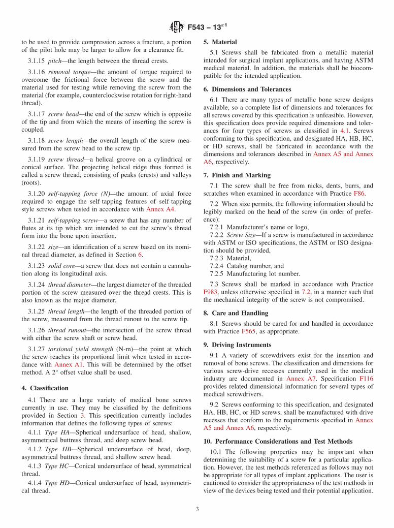
A1.3.3.3 The breaking angle is determined from the torqueversus angle plot shown in Fig. A1.3. The breaking angle isdefined as the point at which the torque portion of the curvedemonstrates its most rapid descent (negative slope) to totalfailure. The breaking angle (B.A.) is determined as the inter-section of the two tangents (D and E) shown in Fig. A1.3. LineE is a tangent to the horizontal portion of the curve whichrepresents maximum torque. Line D is drawn at the curve’smost rapid descent. The intersection of these two lines is thebreaking angle (B.A.) and is recorded to the nearest 10°.
A1.4. Report
A1.4.1 Report the following information for each specimentested:
A1.4.1.1 Screw Identification—Reference any applicableASTM or ISO specification that may apply to the specimen. Ifspecifications do not exist, provide head form, thread form,major and minor diameter, thread pitch, overall screw length,head and shank (unthreaded portion of the screw excluding thehead) length, and type of screw point.
A1.4.1.2 Screw chemical composition.A1.4.1.3 Surface finish.A1.4.1.4 Gage length.
FIG. A1.2 Typical Torque Versus Angle of Rotation Curve
F543 − 13´1
5
A1.4.1.5 Torsional yield strength.
A1.4.1.6 Maximum torque.A1.4.1.7 Breaking angle.A1.4.1.8 Torque versus angle of rotation plot.A1.4.1.9 The size of the exposed portion of the screwdriver
(that is, the length and diameter relative to the tested screw) orthe angular deformation of the screwdriver assembly at maxi-mum torque.
A1.4.1.10 Grip Length—Does not have to be reported for afully threaded screw of ASTM or ISO specification whoseoverall length is given.
A1.4.1.11 Fracture Location—The location can be specifiedby listing the number of threads below the head at which thescrew fails or by measuring the distance below the head to theapproximate fracture point.
A1.5. Precision and Bias
A1.5.1 Data establishing the precision and bias to be ex-pected from this test method have not yet been obtained.
A2. TEST METHOD FOR DRIVING TORQUE OF MEDICAL BONE SCREWS
A2.1. Significance and Use
A2.1.1 This test method is used to measure the torquerequired to drive a bone screw into a standard material. Theresults obtained in this test method bear no direct correlation tothe insertion torque required to insert the subject bone screw inhuman or animal bone. This test method is used only for thepurpose of maintaining the uniformity of the product tested.
A2.2. Apparatus
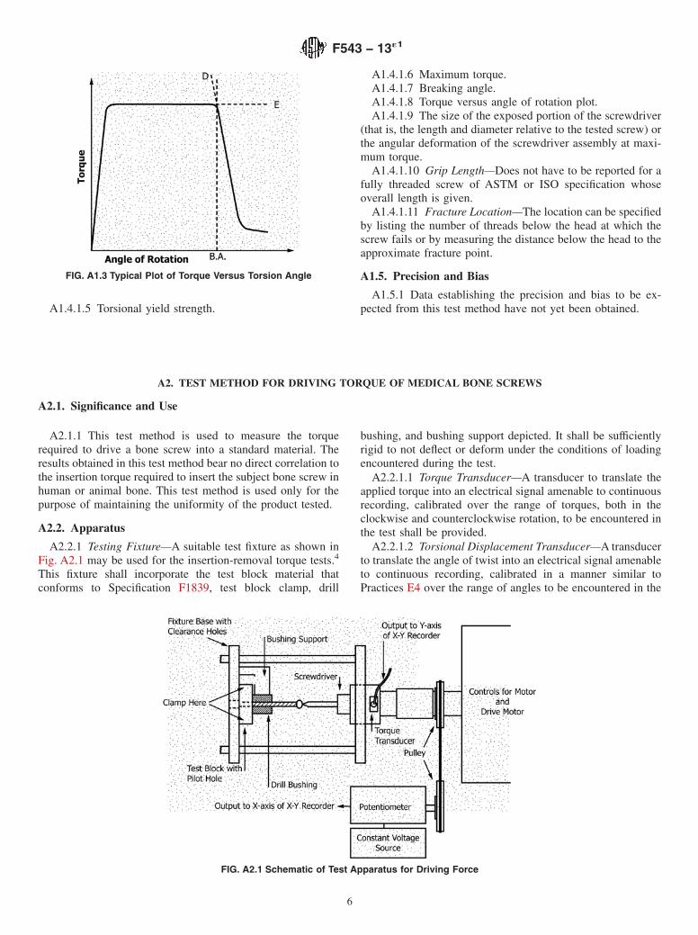
A2.2.1 Testing Fixture—A suitable test fixture as shown inFig. A2.1 may be used for the insertion-removal torque tests.4
This fixture shall incorporate the test block material thatconforms to Specification F1839, test block clamp, drill
bushing, and bushing support depicted. It shall be sufficientlyrigid to not deflect or deform under the conditions of loadingencountered during the test.
A2.2.1.1 Torque Transducer—A transducer to translate theapplied torque into an electrical signal amenable to continuousrecording, calibrated over the range of torques, both in theclockwise and counterclockwise rotation, to be encountered inthe test shall be provided.
A2.2.1.2 Torsional Displacement Transducer—A transducerto translate the angle of twist into an electrical signal amenableto continuous recording, calibrated in a manner similar toPractices E4 over the range of angles to be encountered in the
FIG. A1.3 Typical Plot of Torque Versus Torsion Angle
FIG. A2.1 Schematic of Test Apparatus for Driving Force
F543 − 13´1
6
test to an accuracy of 60.3°, both in the clockwise andcounterclockwise rotation, shall be provided.
A2.2.1.3 Data Recorder—The data recorder shall be suit-able to record torque versus angle of rotation continuously,calibrated in units of newton-metres for torque and degrees forangle of rotation. The value of torque shall have a resolution of10 % of the maximum measured torque. The angular displace-ment scale shall have sensitivity such that at least fourrevolutions can be recorded and displayed.
A2.2.1.4 Bushing—A suitable replaceable bushing, fabri-cated from material that conforms to Specification F1839, shallbe incorporated into the testing fixture. This bushing shall be ofsufficient length and rigidity to ensure that specimens aredriven into the test block normal to the top surface of the testblock. The bore of the bushing shall be of such dimension as toensure guidance of the test specimen with minimum frictionalresistance between the major diameter of the test specimen andthe bore of the bushing. Worn bushings shall be discarded andreplaced with new bushings before conducting the test.
A2.2.1.5 Test Block Clamp—A clamp or holding deviceshall be incorporated into the testing fixture. This holdingdevice shall maintain the drilled pilot hole in the test block inline with the test specimen. The holding device shall notdeform the test block during clamping of the test block orperformance of the test.
A2.2.1.6 Test Specimen—The test specimen shall be acompletely fabricated, finished, and sterilized bone screw ofsufficient length to transverse the bushing and test block.
A2.2.1.7 Test Block—The test block shall be fabricated froma uniform material that conforms to Specification F1839. Thechoice of appropriate foam density for this test is at thediscretion of the user. See Section 8.6.2 of F1839 for additionalinformation. To accommodate the requirements of the pilothole as described in A2.2.1.8, the smallest dimension of the testblock’s surface shall be greater than 10× the diameter of thescrew under test. The top and bottom surfaces shall be flat,smooth, and parallel (within 60.4 mm) as required to ensurethat the test block will be supported in the fixture with the topsurface at an angle of 90° to the centerline of the test specimen.The edges of the test block shall be of such contour orsquareness as required to ensure that the test block clamp shallhold the test block free of relative motion without deformationof the test block during clamping or testing. The test blockthickness shall be not less than 4.8 mm.
A2.2.1.8 Pilot Holes in Test Block—Pilot holes shall bedrilled in the test block for insertion and removal of the testspecimen. The drill size used shall be that specified by thescrew manufacturer, for the size screw being tested. If specifiedby the screw manufacturer, the specified sized tap shall be usedto tap the pilot hole before testing. The holes shall be drilled at90° to the top surface of the test block. The holes shall bedrilled straight and true, free of taper, bell mouth, or barrelshape. If there are multiple holes in one test block, the pilotholes shall be spaced sufficiently far away from test blockedges so that testing does not deform the test block edges.Spacing should have a minimum distance of 5× the diameter of
the screw. When the test block is inserted into the test fixture(Fig. A2.1), the pilot hole, screw, and screwdriver shall be onthe same axis.
A2.3. Sampling
A2.3.1 Representative random samples may be taken fromeach lot or processing quantity in accordance with PracticeE122.
A2.4. Procedure
A2.4.1 Insertion and Removal Torque—Place the specimenin the test fixture as illustrated in Fig. A2.1. Drive the specimeninto the test block, using the appropriate size and configuredscrewdriver bit, by applying a torsional force at a rate of 1 to5 r/min, to the head of the specimen with the motor-driventorque wrench. The insertion torque shall be the maximumreading recorded during the initial four revolutions of thespecimen. The removal torque shall be measured by reversingthe direction of rotation and recording the maximum torquerecorded during the four revolutions required to remove thescrew from the test block. Values should be reported inn\Newton-metres. A 1.14-kgf or less axial load should be usedto maintain the screwdriver bit in the screw head during boththe insertion and removal procedures. If a larger axial load isapplied, this load shall be recorded on the report form. Thisload may be measured by any appropriate method.
A2.5. Report
A2.5.1 The report shall include the following for eachspecimen tested. (All standards units for reporting shall be inSI units.)
A2.5.1.1 Screw Identification—Reference any applicableASTM or ISO standard specification that may apply to thespecimen. If specifications do not exist, provide head form,thread form, major and minor diameter, thread pitch, overallscrew length, head and shank (unthreaded portion of the screwexcluding the head) length, and type of screw point.
A2.5.1.2 Screw chemical composition.A2.5.1.3 Surface finish.A2.5.1.4 Insertion torque.A2.5.1.4.1 Axial load required.A2.5.1.4.2 Insertion depth (may be calculated or measured).A2.5.1.4.3 Specification of whether the pilot holes were or
were not pretapped, if so, specifications of the tap size, tapdiameter, and tap depth shall be reported.
A2.5.1.4.4 Insertion test speed if outside the range specifiedin A2.4.1.
A2.5.1.5 Removal torque.A2.5.1.5.1 Axial load required.A2.5.1.5.2 Insertion test speed if outside the range specified
in A2.4.1.A2.5.1.6 Test Block Material Description—Specification
F1839 grade. For bushing material that does not conform toSpecification F1839, provide
A2.6.1 Data establishing the precision and accuracy to beexpected from this test method have not yet been obtained.
A3. TEST METHOD FOR DETERMINING THE AXIAL PULLOUT STRENGTH OF MEDICAL BONE SCREWS
A3.1. Significance and Use
A3.1.1 This test method is used to measure the axial tensileforce required to fail or remove a bone screw from a definedmaterial. The results obtained in this test method are notintended to predict the force required to remove the subjectbone screw from human or animal bone. This test method isintended only to measure the uniformity of the products testedor to compare the strength of different products.
A3.1.2 This test method may not be appropriate for all typesof implant applications. The user is cautioned to consider theappropriateness of the method in view of the materials beingtested and their potential application.
A3.2. Apparatus
A3.2.1 Test Fixture—Machines used for testing the axialpullout strength of screws shall conform to the requirements ofPractices E4. A suitable test fixture as shown in Fig. A3.1 maybe used for testing. This fixture shall incorporate the test blockmaterial which conforms to Specification F1839, test blockclamp, drill bushing, and bushing support depicted in theinsertion torque test method, Annex A2. In addition to theserequirements, the test block clamp and bushing support shouldbe sufficiently rigid such that deflection under the required
loading conditions is negligible. The test block clamp shouldhave a minimum grip span of five times the major diameter ofthe bone screw with the screw centered between the grips. Thegrip span should be consistent throughout testing.
A3.2.2 Test Block—The test block shall be fabricated from auniform material that conforms to Specification F1839. Thechoice of appropriate foam density for this test is at thediscretion of the user. See Section 8.6.2 of F1839 for additionalinformation. The top and bottom surfaces shall be flat, smooth,and parallel (within 60.4 mm) as required to ensure that thetest block will be supported in the fixture with the top surfaceat an angle of 90° to the centerline of the test specimen. Theedges of the test block shall be of such contour or squarenessas required to ensure that the test block clamp shall hold thetest block free of relative motion without deformation of thetest block during clamping or testing. The test block thicknessshall be not less than 20 mm.
A3.2.3 Data Acquisition Device—The data recorder shall besuitable to continuously record load versus load fixture dis-placement.
A3.2.4 Load Frame—Machines used for testing shall con-form to the requirements of Practices E4. The loads used forthe test method shall be within the loading range of the testmachine as defined in Practices E4.
A3.2.5 Load Fixture—A suitable fixture shall be used toplace a tensile load on the bone screw. The load shall betransferred through the head of the screw and should be alignedwith the screw’s longitudinal axis. The fixture shall have a slotto capture the head of the screw without contact being madewith the screw’s shaft. To ensure proper alignment, the slotshall have a spherical recess into which the screw head can beseated directly under the applied load.
A3.3. Sampling, Test Specimens, and Test Units
A3.3.1 All test components shall be representative of im-plant quality products.
A3.4. Procedure
A3.4.1 Insertion of the Test Specimen—The bone screwsshall be inserted into the standard material in accordance withthe insertion torque test method, Annex A2. The screws shallbe inserted at a rate of 3 r/min to a depth of 20 mm. For fullythreaded screws with threaded lengths less than 20 mm, theFIG. A3.1 Schematic of Test Apparatus for Pullout Strength
F543 − 13´1
8
insertion depth should be 60 % of the threaded length of thescrew. Partially threaded bone screws should have all threadsinserted into the standard material.
A3.4.2 Axial Pullout Strength of the Test Specimen—Thetest block and test block clamp depicted in Annex A2 shall befixed to the base of the load frame so that the longitudinal axisof the screw is aligned with the direction of the applied load.The screw’s head shall be placed in the slot of the load fixtureand seated in the spherical recess. The load fixture shall then beattached to the load frame. A tensile load shall be applied to thetest specimen at a rate of 5 mm/min until the screw fails orreleases from the test block. Load (newtons) versus load fixturedisplacement (millimetres) shall be recorded on a data acqui-sition device, noting the maximum load applied and the modeof failure (screw shaft, screw threads, or material failure).
A3.5. Calculation or Interpretation of Results
A3.5.1 Axial Pullout Strength—Determine the axial pulloutstrength (in Newtons) of the test specimen from the load-displacement curve. The maximum load is reached during thetest method.
A3.6. Report
A3.6.1 Report the following information:A3.6.1.1 Screw Identification—Reference any applicable
ASTM or ISO standard specification that may apply to the
specimen. If specifications do not exist, provide head form,thread form, helix angle, major and minor diameter, threadpitch, overall screw length, head and shank length, length ofthreaded portion of shank for partially threaded screws, andtype of screw point.
A3.6.1.2 Screw chemical composition.A3.6.1.3 Surface finish.A3.6.1.4 Axial pullout strength (as defined in 3.1.1).A3.6.1.5 Grip span.A3.6.1.6 Insertion depth.A3.6.1.7 Test block thickness.A3.6.1.8 Mode of failure.A3.6.1.9 Test Block Material Description—Specification
F1839 grade or density. For materials that do not conform toF1839, provide the following information and the appropriatetest methods used to determine the properties of the test blockmaterial:
A3.7.1 Data establishing the precision and accuracy to beexpected from this test method have not yet been obtained.
A4. TEST METHOD FOR DETERMINING THE SELF-TAPPING PERFORMANCE OF SELF-TAPPING MEDICAL BONESCREWS
A4.1 Significance and Use
A4.1.1 This test method is used to determine the axialcompression load (force) required to engage the self-tappingfeature of self-tapping medical bone screws into a standardmaterial. The results obtained in this test method bear no directcorrelation to the axial force required to insert the subject bonescrew in human or animal bone. This test method is used onlyto measure uniformity of the product tested or to compare theperformance of different, yet similarly sized, products. This testmethod is not applicable to “self-drilling” or “self-drilling/self-tapping” styles of medical bone screws.
A4.2 Apparatus
A4.2.1 Testing Apparatus—A schematic for the axial self-tapping force test apparatus is illustrated in Fig. A4.1. Theapparatus shall provide a variable speed motor capable ofcontinuously driving a spindle. The spindle shall be capable ofa continuous rotation as well as axial translation to allowvariable force on the test specimen. The apparatus and spindleshall be sufficiently rigid to neither deflect nor deform underthe conditions of loading encountered during the test. Theapparatus shall incorporate a test block clamp for purpose ofrigidly fixing a test block. The apparatus shall be capable of
FIG. A4.1 Schematic of Test Apparatus for Determination of Self-Tapping Force
F543 − 13´1
9
continuously monitoring and recording the force, torque, andaxial displacement of the specimen. The apparatus shall becalibrated for the range of forces, torques, and linear displace-ments used in the determination.
A4.2.2 Compression Load Cell—A transducer to translatethe applied axial force into an electrical signal suitable forcontinuous recording and calibrated over the range of forces tobe encountered in the test method, shall be provided. The loadcell should have an accuracy of 0.5 % of full-scale output andallow measurement resolution of 61.0 N.
A4.2.3 Torque Transducer—A transducer to translate theapplied torque into an electrical signal suitable for continuousrecording and calibrated over the range of torques, both inclockwise and counterclockwise rotation, to be encountered inthe test method, shall be provided. The torque transducershould have an accuracy of 0.5 % of full-scale output and allowmeasurement resolution of 60.10 N-m.
NOTE A4.1—A combination compressive load and torque transducer issuitable for this application provided the transducer meets the specifica-tions detailed in A4.2.2 and A4.2.3.
A4.2.4 Linear Displacement Transducer—A transducer totranslate the axial displacement of the test apparatus’ spindleinto an electrical signal suitable for continuous recording andcalibrated over the range of displacements to be encountered inthe test method, shall be provided. The displacement trans-ducer should have an accuracy of 1 % of full scale and allowa measurement resolution of 60.5 mm.
A4.2.5 Test Block Clamp—A clamp or holding device shallbe incorporated into the testing fixture. This holding deviceshall maintain the drilled pilot hole in the test block in line withthe test specimen. The holding device shall be sufficiently rigidto neither deflect nor deform under the conditions of loadingencountered during the test and yet not deform the test blockduring clamping of the test block or performance of the test.
A4.2.6 Test Block—The test block shall be fabricated from auniform material that conforms to Specification F1839. The topand bottom surfaces shall be flat, smooth, and parallel (within0.4 mm) as required to ensure that the test block will besupported in the fixture with the top surface at an angle of 90°to the centerline of the test specimen. The edges of the testblock shall be of such contour or squareness as required toensure that the test block clamp shall hold the test block free ofrelative motion without deformation of the test block duringclamping or testing. The test block thickness shall be not lessthan 25 mm.
A4.2.7 Pilot Holes in Test Block—Pilot holes shall be drilledin the test block for insertion and removal of the test specimen.The drill size used shall be that specified by the screwmanufacturer for the size screw being tested. The holes shall bedrilled at 90° to the top surface of the test block. The holesshall be drilled straight and true, free of taper, bell mouth, orbarrel shape. The holes should be drilled completely throughthe test block and all particulate debris removed prior toinserting the test specimen. If there are multiple holes in onetest block, the pilot holes shall be spaced sufficiently far awayfrom test block edges so that testing does not deform test block
edges. Spacing should have a minimum distance as recom-mended in A2.2.1.8. When the test block is inserted into thetest fixture (Fig. A4.1), the pilot hole, screw, and screwdrivershall be on the same axis.
A4.2.8 Test Specimen—The test specimen shall be a com-pletely fabricated and finished bone screw of sufficient lengthto allow completion of the test.
A4.2.9 Recorder—The data recorder shall be suitable torecord continuously, at a minimum rate of 10 Hz, axialcompression force, torque, and axial spindle displacement. Therecorder shall be capable of recording two Y axes simultane-ously (force and torque to Y Axis 1 and displacement to Y Axis2) versus time (X axis), calibrated in units of Newtons forforce, Newton-metres for torque, and millimetres for displace-ment. The value of force and torque should have a resolution of0.5 % of full-scale output and sensitivity so as to enable anaccurate recording capability of a minimum of 1.0 N and 0.10N-m, respectively. The value of torque shall have a resolutionof 0.5 % of full-scale output. The linear displacement scaleshould have a minimum sensitivity so as to enable an accuraterecording capability for 0.5 mm.
A4.2.10 Test Speed—The torsional force shall be applied ata constant rate of 30 r/min. The axial compression force shallbe applied at a constant rate of approximately 2 N/s. Thetorsional test speed has been selected to represent the clinicalsituation of hand-driven screws. The axial load rate has beenselected to allow easy identification and reaction to the uniqueself-tap events on the data output recorder. Other test speedsand load rates can be used provided they are justified andreported. All comparative tests shall be performed at the sametest speeds.
A4.3 Sampling
A4.3.1 Representative random samples may be taken fromeach lot or processing quantity in accordance with PracticeE122.
A4.4 Procedure
A4.4.1 Self-Tapping Force—The pre-drilled test block isrigidly fixed in the test block clamp device shown in Fig. A1.1.The appropriate sized screwdriver (“driver”) is inserted into thespindle and the alignment of the pilot hole with the driver isverified. The self-tapping bone screw specimen is then pre-assembled (“loaded”) onto the driver. The specimen/driverassembly is then lowered via the spindle into the pilot hole andthe axial displacement of the spindle adjusted to achieve amaximum preload of 1.0 N to maintain screw-to-screwdriverengagement.
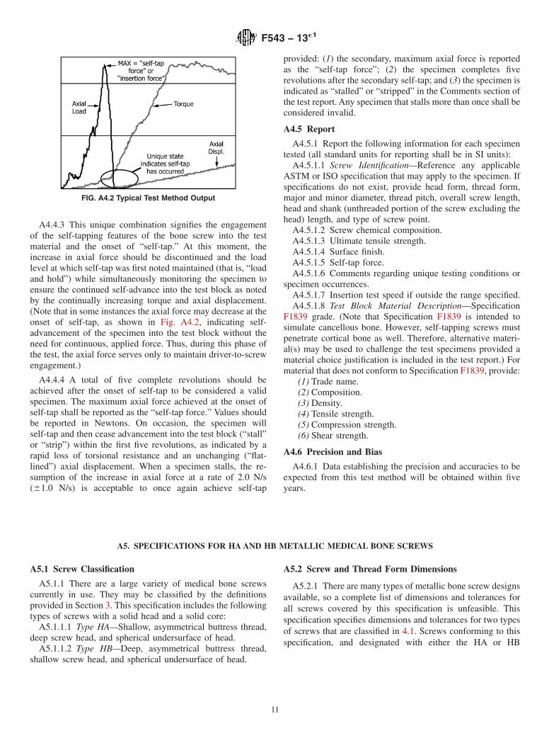
A4.4.2 The specimen is then driven by the test apparatus ata constant rotational rate of 30 revolutions/minute (r/min). Theaxial force, torque, and displacement channels on the datarecorder are monitored simultaneously while the axial force isincreased at a rate of approximately 2.0 N/s (6 1.0 N/s). Theaxial compression force shall continue to be increased until theself-tapping features of the screw engage the test block asindicated by a marked increase in torque and axial displace-ment are observed as shown in Fig. A4.2.
F543 − 13´1
10
A4.4.3 This unique combination signifies the engagementof the self-tapping features of the bone screw into the testmaterial and the onset of “self-tap.” At this moment, theincrease in axial force should be discontinued and the loadlevel at which self-tap was first noted maintained (that is, “loadand hold”) while simultaneously monitoring the specimen toensure the continued self-advance into the test block as notedby the continually increasing torque and axial displacement.(Note that in some instances the axial force may decrease at theonset of self-tap, as shown in Fig. A4.2, indicating self-advancement of the specimen into the test block without theneed for continuous, applied force. Thus, during this phase ofthe test, the axial force serves only to maintain driver-to-screwengagement.)
A4.4.4 A total of five complete revolutions should beachieved after the onset of self-tap to be considered a validspecimen. The maximum axial force achieved at the onset ofself-tap shall be reported as the “self-tap force.” Values shouldbe reported in Newtons. On occasion, the specimen willself-tap and then cease advancement into the test block (“stall”or “strip”) within the first five revolutions, as indicated by arapid loss of torsional resistance and an unchanging (“flat-lined”) axial displacement. When a specimen stalls, the re-sumption of the increase in axial force at a rate of 2.0 N/s(61.0 N/s) is acceptable to once again achieve self-tap
provided: (1) the secondary, maximum axial force is reportedas the “self-tap force”; (2) the specimen completes fiverevolutions after the secondary self-tap; and (3) the specimen isindicated as “stalled” or “stripped” in the Comments section ofthe test report. Any specimen that stalls more than once shall beconsidered invalid.
A4.5 Report
A4.5.1 Report the following information for each specimentested (all standard units for reporting shall be in SI units):
A4.5.1.1 Screw Identification—Reference any applicableASTM or ISO specification that may apply to the specimen. Ifspecifications do not exist, provide head form, thread form,major and minor diameter, thread pitch, overall screw length,head and shank (unthreaded portion of the screw excluding thehead) length, and type of screw point.
A4.5.1.2 Screw chemical composition.A4.5.1.3 Ultimate tensile strength.A4.5.1.4 Surface finish.A4.5.1.5 Self-tap force.A4.5.1.6 Comments regarding unique testing conditions or
specimen occurrences.A4.5.1.7 Insertion test speed if outside the range specified.A4.5.1.8 Test Block Material Description—Specification
F1839 grade. (Note that Specification F1839 is intended tosimulate cancellous bone. However, self-tapping screws mustpenetrate cortical bone as well. Therefore, alternative materi-al(s) may be used to challenge the test specimens provided amaterial choice justification is included in the test report.) Formaterial that does not conform to Specification F1839, provide:
A4.6.1 Data establishing the precision and accuracies to beexpected from this test method will be obtained within fiveyears.
A5. SPECIFICATIONS FOR HA AND HB METALLIC MEDICAL BONE SCREWS
A5.1 Screw Classification
A5.1.1 There are a large variety of medical bone screwscurrently in use. They may be classified by the definitionsprovided in Section 3. This specification includes the followingtypes of screws with a solid head and a solid core:
A5.1.1.1 Type HA—Shallow, asymmetrical buttress thread,deep screw head, and spherical undersurface of head.
A5.1.1.2 Type HB—Deep, asymmetrical buttress thread,shallow screw head, and spherical undersurface of head.
A5.2 Screw and Thread Form Dimensions
A5.2.1 There are many types of metallic bone screw designsavailable, so a complete list of dimensions and tolerances forall screws covered by this specification is unfeasible. Thisspecification specifies dimensions and tolerances for two typesof screws that are classified in 4.1. Screws conforming to thisspecification, and designated with either the HA or HB
FIG. A4.2 Typical Test Method Output
F543 − 13´1
11
classification shall be fabricated in accordance with the dimen-sions and tolerances in this Annex in accordance with thefollowing requirements.
A5.2.1.1 Type HA:(1) Screw Dimensions— The dimensions of HA screws are
given in Table A5.1 and Fig. A5.1.(2) Screw Thread— The dimensions of the threads of HA
screws are given in Table A5.2 and Fig. A5.2.A5.2.1.2 Type HB:
(1) Screw Dimensions— The dimensions of HB screws aregiven in Table A5.3 and Fig. A5.3.
(2) Screw Thread— The dimensions of the threads of HBscrews are given in Table A5.4 and Fig. A5.4.
A5.3 Drive Connections
A5.3.1 Screws conforming to this specification, and desig-nated with either the HA or HB classification shall be fabri-cated with the following drive connections in accordance withthe dimensions and tolerances found in Annex A7.
A5.3.1.1 Type HA—Hexagonal recess for accepting theSpecification F116 Type IV—Hexagonal bit.
A5.3.1.2 Type HB—Hexagonal recess for accepting theSpecification F116 Type IV—Hexagonal bit.
A5.4 Performance Requirements
A5.4.1 Screws that meet the dimensional requirements ofthe HA or HB screws in A5.2 shall also meet the followingmechanical performance requirements.
A5.4.1.1 Maximum Torque:(1) A minimum of five screws for a particular type and size
shall be tested in accordance with the test methods described inAnnex A1, with five threads exposed in the gage length.
(2) The maximum torque of all screws within the sample ofscrews from a particular type and size of screw shall meet orexceed the requirements provided in Table A5.5.
A5.4.1.2 Breaking Angle:(1) A minimum of five screws for a particular type and size
shall be tested in accordance with the methods described inAnnex A1, with five threads exposed in the gage length.
(2) The breaking angle of all screws within the sample ofscrews from a particular type and size of screw shall meet orexceed the requirements provided in Table A5.5.
TABLE A5.1 Dimensions for HA Screws (Fig. A5.1)
Screw Type and Size Head Diameter, d2 Head Height, k Bottom Head Radius,r1
Top Head Radius, r2 Tip Radius, r3 ScrewdriverSizeA
HB 6.5 6.2 90†Unit of measure was editorially corrected.
F543 − 13´1
14
A6. SPECIFICATIONS FOR HC AND HD METALLIC MEDICAL BONE SCREWS
A6.1 Screw Classification
A6.1.1 There are a large variety of medical bone screwscurrently in use. They may be classified by the definitionsprovided in Section 4. This specification includes the followingtypes of screws with a solid head and a solid core:
A6.1.1.1 Type HC— Conical undersurface of head, sym-metrical thread.
A6.1.1.2 Type HD— Conical undersurface of head, asym-metrical thread.
A6.2 Screw and Thread Form Dimensions
A6.2.1 There are many types of metallic bone screw designsavailable, so a complete list of dimensions and tolerances forall screws covered by this specification is unfeasible. Thisspecification specifies dimensions and tolerances for two typesof screws that are classified in 4.1. Screws conforming to thisspecification, and designated with either the HC or HDclassification shall be fabricated in accordance with the dimen-sions and tolerances in this Annex in accordance with thefollowing requirements.
A6.2.1.1 Type HC:(1) Screw Dimensions—The dimensions of HC screws are
given in Table A6.1 and Fig. A6.1.(2) Screw Thread—The dimensions of the threads of HC
screws are given in Table A6.2 and Fig. A6.2.A6.2.1.2 Type HD:
(1) Screw Dimensions—The dimensions of HD screws aregiven in Table A6.3 and Fig. A6.3.
(2) Screw Thread—The dimensions of the threads of HDscrews are given in Table A6.4 and Fig. A6.4.
A6.3 Drive Connections
A6.3.1 Screws conforming to this specification, and desig-nated with either the HC or HD classification shall be fabri-cated with the following drive connections in accordance withthe dimensions and tolerances found in Annex A7.
A6.3.1.1 Type HC:(1) Single-slot recess for accepting the Specification F116
Type I—single-slot bit.(2) Cruciate recess for accepting the Specification F116
Type II—cruciate-slot bit.(3) Combined cruciate-slot and cross-slot recess for accept-
ing either the Specification F116 Type II—cruciate-slot or TypeIII—cross-slot (modified Phillips) bits.
A6.3.1.2 Type HD—Combined single-slot and cross-slotrecess for accepting either the Specification F116 TypeI—single-slot or Type III—cross-slot (modified Phillips) bits.
A6.4 Performance Requirements
A6.4.1 Screws that meet the dimensional requirements ofthe HC or HD screws in A6.2 shall be tested to document thefollowing mechanical performance characteristics.
A6.4.1.1 Torsional strength—A minimum of five screws fora particular type and size shall be tested in accordance with themethods described in Annex A1, with five threads exposed inthe gage length.
A6.4.1.2 Breaking angle—A minimum of five screws for aparticular type and size shall be tested in accordance with themethods described in Annex A1, with five threads exposed inthe gage length.
FIG. A6.1 Schematic of HC Screw Dimensions (Table A6.1)
F543 − 13´1
15
FIG. A6.2 Schematic of HC Screw Thread Dimensions (Table A6.2)
FIG. A6.3 Schematic of HD Screw Dimensions (Table A6.3)
FIG. A6.4 Schematic of HD Screw Thread Dimensions (Table A6.4)
A7. SPECIFICATIONS FOR METALLIC BONE SCREW DRIVE CONNECTIONS
A7.1. Scope
A7.1.1 This annex specifies the requirements for a variety ofdrive connections that can be implemented in metallic medicalbone screws. The screw’s drive connection supplies the inter-connection that is typically used in orthopedic surgery forinserting and removing bone screws.
A7.2 Classification
A7.2.1 There are many methods that can be used to classifymedical bone screws. The majority of the methods currentlybeing used in the medical industry can be found in Section 3 ofthis specification. An additional characteristic not covered inSection 3 is the bone screw’s drive connection. This specifi-cation describes the following drive connections that arecompatible with the noted screwdriver bits.
A7.2.1.1 Single-Slot—This drive connection is illustrated inFig. A7.1. Screws manufactured with this drive connection canbe driven with the Specification F116 Type I—single-slot bit orthe ISO 8319/2 single-slot screwdriver bit.
A7.2.1.2 Cross-Recessed—This drive connection is illus-trated in Fig. A7.2. Screws manufactured with this driveconnection can be driven with the Specification F116 TypeIII—cross-slot (modified Phillips) bit or the ISO 8319/2cross-recessed head screwdriver bit.
A7.2.1.3 Combined Single-Slot and Cross-Recessed—Thisdrive connection is illustrated in Fig. A7.3. Screws manufac-tured with this drive connection can be driven with the F116Type I—single-slot bit, Specification F116 Type III—cross-slot(modified Phillips) bit, the ISO 8319/2 single-slot screwdriverbit, or the ISO 8319/2 cross-recessed head screwdriver bit.
A7.2.1.4 Cruciate-Slot—This drive connection is illustratedin Fig. A7.4. Screws manufactured with this drive connectioncan be driven with the Specification F116 Type I—single-slotbit, Specification F116 Type II—cruciate-slot bit, the ISO8319/2 single-slot screwdriver bit, or the ISO 8319/2 cruciate-slot screwdriver bit.
TABLE A6.2 Dimensions for HC Screw Thread (Fig. A6.2)
TABLE A6.4 Dimensions for HD Screw Thread (Fig. A6.4)
ScrewTypeandSize
ThreadDiameter,
d1
CoreDiameter,
d5
CrestWidth,
e
ThreadPitch,
P
LeadingEdgeAngle,
α
TrailingEdgeAngle,
βHD 4 3.97 – 4.03 2.89 – 2.95 0.1 1.59 45 10
HD 4.5 4.47 – 4.53 2.89 – 2.95 0.1 2.18 45 10
FIG. A7.1 Schematic of Screw with Single-Slot Drive Connection(Table A7.1)
FIG. A7.2 Schematic of Screw with Cross-Recessed Drive Con-nection (Table A7.2)
F543 − 13´1
17
A7.2.1.5 Combined Cruciate-Slot and Cross-Recessed—This drive connection is illustrated in Fig. A7.5. Screwsmanufactured with this drive connection can be driven with theSpecification F116 Type I—single-slot bit, F116 Type II—cruciate-slot bit, the Specification F116 Type III—Cross-slot(modified Phillips) bit, the ISO 8319/2 single-slot screwdriverbit, ISO 8319/2 cruciate-slot screwdriver bit, or the ISO 8319/2crossed-recessed head screwdriver bit.
A7.2.1.6 Hexagonal—This drive connection is illustrated inFig. A7.6. Screws manufactured with this drive connection canbe driven with the Specification F116 Type IV—hexagonal orthe ISO 8319/1 hexagonal screwdriver bit.
A7.2.1.7 Square—This drive connection is illustrated in Fig.A7.7. At this time no standard screwdriver bit is specified forthis drive connection. Screws manufactured with this driveconnection can be driven with square drive screwdriver bits.
A7.2.1.8 Hexalobe—This drive connection is illustrated inFig. A7.8. At this time no standard screwdriver bit is specifiedfor this drive connection. Screws manufactured with this driveconnection can be driven with hexalobe (six-lobe) screwdriverbits that conform to ISO 10664 Standard for Hexobular internaldriving feature for bolts and screws..
A7.3 Dimensions
A7.3.1 Medical bone screws conforming to this specifica-tion are as follows:
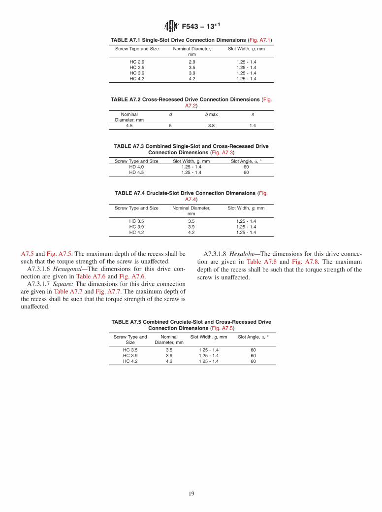
A7.3.1.1 Single-Slot—The dimensions for this drive con-nection are given in Table A7.1 and Fig. A7.1.
A7.3.1.2 Cross-Recessed—The dimensions for this driveconnection are given in Table A7.2 and Fig. A7.2.
A7.3.1.3 Combined Single-Slot and Cross-Recessed—Thedimensions for this drive connection are given in Table A7.3and Fig. A7.3. The maximum depth of the recess shall be suchthat the torque strength of the screw is unaffected.
A7.3.1.4 Cruciate-Slot—The dimensions for this drive con-nection are given in Table A7.4 and Fig. A7.4.
A7.3.1.5 Combined Cruciate-Slot and Cross-Recessed—The dimensions for this drive connection are given in Table
FIG. A7.3 Schematic of Screw with Combined Single-Slot andCross-Recessed Drive Connection (Table A7.3)
FIG. A7.4 Schematic of Screw with Cruciate-Slot Drive Connec-tion (Table A7.4)
FIG. A7.5 Schematic of Screw with Combined Cruciate-Slot andCross-Recessed Drive Connection (Table A7.5)
FIG. A7.6 Schematic of Screw with Hexagonal Drive Connection(Table A7.6)
FIG. A7.7 Schematic of Screw with Square Drive Connection(Table A7.7)
FIG. A7.8 Schematic of Screw with Hexalobe Drive Connection(Table A7.8)
F543 − 13´1
18
A7.5 and Fig. A7.5. The maximum depth of the recess shall besuch that the torque strength of the screw is unaffected.
A7.3.1.6 Hexagonal—The dimensions for this drive con-nection are given in Table A7.6 and Fig. A7.6.
A7.3.1.7 Square: The dimensions for this drive connectionare given in Table A7.7 and Fig. A7.7. The maximum depth ofthe recess shall be such that the torque strength of the screw isunaffected.
A7.3.1.8 Hexalobe—The dimensions for this drive connec-tion are given in Table A7.8 and Fig. A7.8. The maximumdepth of the recess shall be such that the torque strength of thescrew is unaffected.
X1.1 This specification is intended to provide useful andconsistent information related to the performance, terminology,requirements for materials, finish and marking considerations,and care and handling of metallic bone screws. It includes theterms and requirements of Specification F543-98. This speci-fication also includes the test methods that were previouslypublished separately as Specifications F117, F1622, andF1691.5
X1.2 Materials which have been found acceptable for me-tallic bone screws includes:
X1.3 Dimensional requirements are provided for four spe-cific types of bone screws. These screws, specified here asSpecification F543 Types HA and HB, HC, and HD aredimensionally similar to those specified in ISO 5835 and ISO9268. The dimensions and performance of these types ofscrews are specified because they have achieved widespreadclinical use and are offered by several manufacturers. Stan-dardization of the dimensions and tolerances of the keyfeatures of these screws is intended to allow the implants fromone manufacturer to be used with the associated instruments(taps, drills, and so forth) from different manufacturers andserve as a baseline for future screw products. This may benefitthe surgeon and patient by aiding the identification of theappropriate instrumentation for the implantation and removalof screws by the operating room staff.
X1.4 Performance requirements are provided for two spe-cific types of bone screws. Those that have a solid core and aspherical head, specified here as Specification F543 Type HAand HB, have performance specifications developed from thosespecified in ISO 6475. Standardization of the performancerequirements and harmonization of these requirements with thesimilar screws described in ISO standards is intended tofacilitate the approval to market for manufacturers declaringconformity to either or both standards.
X1.5 This specification provides minimum performancelimits for the torsional properties of bone screws and a uniformtest procedure by which these limits can be determined. Theparameters specified in this specification are breaking torqueand breaking angle.
X1.5.1 The breaking torque is intended to be a measure ofthe screw’s strength. Torque was determined to be the criticalparameter in the insertion of screws into a uniform medium.Unpublished test reports indicated that a screw could experi-ence both torsional and tensile forces when inserted into auniform medium. If the screw was inserted until it ruptured,then the torsional forces appear to dominate over the tensileforces. Therefore, tensile forces were neglected in analyzingscrew strength.
X1.5.2 The breaking angle is a measure of the screw’sductility. For example, a screw that has a breaking angle of360° is more ductile than one with the same design that breaksat 120° under the same test conditions. Since this parameterdoes not represent the point at which the screw loses its elasticproperties, a torsional yield measurement was devised. Thispoint is intended to present an approximate measure of thetorque at which the screw loses its elastic properties. The taskforce decided that an offset method with a 2° angle offsetmethod was considered to yield the most consistent results.
X1.5.3 The breaking force test method provides a consistentmeasurement method for fully threaded bone screws. For
partially threaded screws, the length of the unthreaded portionof the screw and the threaded portion can vary considerablyamong different types of screws. Because of this variation, noexact method of fixation is required. Suggestions are made togrip enough threads to hold the screw in a fixed position withpossibly one or more thread(s) exposed. If this condition is notpossible, then all threads must be gripped. In any case, theexperiment is required to record the gage length and thegripping length.
X1.5.4 If an axial force is necessary to engage the screw-driver in the screw head, the value of this force shall bedetermined by the operator. The force should be the minimumneeded to engage the screwdriver bit with the screw head.
X1.6 This specification provides a uniform test procedurefor measuring the insertion and removal torque of bone screwsin a specified medium. This specification can thus provide ameasure of the uniformity of the products tested or compare theinsertion and removal torque among similar or dissimilarscrews.
X1.6.1 The test method specifies that the bone screw bedriven at a rate of 1 to 5 r/min into the test block. The ratespecified in the original Test Method F1175 standard wasselected and based upon the limitations of torsion test systemswhen the standard was originally developed. Faster drivingrates (an order of magnitude greater at 30 r/min) can bettersimulate the clinical situation for hand-driven screws.Therefore, the user may choose to use higher screw-drivingrates, as long as the selected rate is justified and reported. Allcomparative test methods must be performed at the samedriving rate.
X1.6.2 During the development of this test method, thecommittee noted the need to test sterilized screws. InfectionControl and Sterilization Technology, V4, No 8 p12, August1998 reported differences in the driving torque when sterilizedand unsterilized screws were tested.
X1.7 This specification provides a uniform test procedurefor measuring the axial pullout strength of bone screws from aspecified medium. This specification can provide a measure ofthe uniformity of the products tested or compare the pulloutstrength among similar or dissimilar screws.
X1.8 During the 2011 periodic review of the standard, thesubcommittee received comments from members noting thatSpecification F543 did not include manufacturing tolerancesfor the dimensions in the specifications for Type V Square andType VI Hexalobe screwdriver connections. The subcommitteeestablished that there are no published tolerances for the TypeV Square connection. However, a standard relevant to Type VIHexalobe was identified (ISO 10664) and is included as areference. The subcommittee believes that deletion of theinformation on these connections from the standard will detractfrom the value of the standard as a whole.
F543 − 13´1
21
ASTM International takes no position respecting the validity of any patent rights asserted in connection with any item mentionedin this standard. Users of this standard are expressly advised that determination of the validity of any such patent rights, and the riskof infringement of such rights, are entirely their own responsibility.
This standard is subject to revision at any time by the responsible technical committee and must be reviewed every five years andif not revised, either reapproved or withdrawn. Your comments are invited either for revision of this standard or for additional standardsand should be addressed to ASTM International Headquarters. Your comments will receive careful consideration at a meeting of theresponsible technical committee, which you may attend. If you feel that your comments have not received a fair hearing you shouldmake your views known to the ASTM Committee on Standards, at the address shown below.
This standard is copyrighted by ASTM International, 100 Barr Harbor Drive, PO Box C700, West Conshohocken, PA 19428-2959,United States. Individual reprints (single or multiple copies) of this standard may be obtained by contacting ASTM at the aboveaddress or at 610-832-9585 (phone), 610-832-9555 (fax), or [email protected] (e-mail); or through the ASTM website(www.astm.org). Permission rights to photocopy the standard may also be secured from the Copyright Clearance Center, 222Rosewood Drive, Danvers, MA 01923, Tel: (978) 646-2600; http://www.copyright.com/