266
STANDARD SPECIFICATIONS Daphne Utilities Approved: September 1992 Last Amended: January 2019

STANDARD SPECIFICATIONS
Daphne Utilities
Approved: September 1992 Last Amended: January 2019

i
DAPHNE UTILITIES
STANDARD SPECIFICATIONS
INDEX TITLE PAGE NO. DIVISION I - SUBMITTAL REQUIREMENTS Guidelines for Developers, Engineers & Architects I-1 - I-4 Application for Approval to Construct Sanitary Sewer I-5 - I-9
and/or Water Distribution and/or Gas Facilities DIVISION II - DESIGN CRITERIA A. General Criteria II-1 - II-3 B. Sanitary Sewer System Design Criteria II-3 - II-6 C. Water System Design Criteria II-6 - II-7 D. Gas System Design Criteria II-7 - II-9 E. Summary At A Glance of Key Components II-10 - II-11 DIVISION III - CONSTRUCTION SPECIFICATIONS SECTION 1 - General Specifications for Water Mains 1.01 - Scope 1-1 1.02 - Work Included 1-1 1.03 - Schedule of Operations 1-1 1.04 - Materials 1-1 - 1-13 1.05 - Inspection 1-13 - 1-14 1.06 - Handling Pipe and Accessories 1-14 1.07 - Removing and Replacing Pavement 1-14 1.08 - Alignment and Grade 1-15 1.09 - Excavation and Preparation of Trench 1-15 - 1-17 1.10 - Pipe Laying 1-17 - 1-18 1.11 - Jointing Pipe 1-18 1.12 - Setting Valves, Valve Boxes, Fittings and Blow-Offs 1-18 - 1-19 1.13 - Setting Hydrants 1-19 1.14 - Plugging Dead Ends 1-20 1.15 - Anchorage of Bends, Tees and Plugs 1-20 1.16 - Hydrostatic Testing 1-20 - 1-22 1.17 - Chlorination of Completed Pipeline 1-22 - 1-24 1.18 - Concrete 1-24 1.19 - Backfilling 1-24 1.20 - Erosion Control 1-24 1.21 - Maintenance of Surfaces 1-24 1.22 - Clean-Up 1-24 1.23 - Pressure Tests and Chlorination Adjacent to Existing Water Lines 1-25 1.24 - Existing Water System 1-25 1.25 - Dust Control 1-25 1.26 - Public Safety 1-25 1.27 - Tapping of Water Mains 1-25 1.28 - Extra Depth for Water Lines 1-26 1.29 - Use of Chemicals 1-26

ii
INDEX TITLE PAGE NO. SECTION 1 - General Specifications for Water Mains Cont. 1.30 - Permits, Certificates, Laws and Ordinances 1-26 1.31 - Underground Utilities 1-26 1.32 - Shop Drawings and Record Drawings 1-26 1.33 - Abandoned Water Mains and Appurtenances 1-27 1.34 - Project Documentation 1-27 - 1-28 SECTION 2 - General Specifications for Water Pumping Stations 2.01 - Scope 2-1 2.02 - Location 2-1 2.03 - Pumping Stations 2-1 - 2-2 2.04 - Pumps 2-2 2.05 - Booster Pump Station 2-2 - 2-14 2.06 - Appurtenances 2-14 - 2-15 2.07 - Inspection 2-15 2.08 - Installation 2-15 - 2-16 2.09 - Field Quality Control 2-16 2.10 - Cleaning 2-16 2.11 - Protection 2-16 2.12 - Quality Assurance 2-16 - 2-17 2.13 - Record Drawings 2-17 - 2-18 2.14 - Warranty 2-18 2.15 - Emergency Standby Power 2-18 2.16 - Shop Drawings and Record Drawings 2-18 SECTION 3 - General Specifications for Sanitary Sewer Mains 3.01 - Scope 3-1 3.02 - Work Included 3-1 3.03 - Schedule of Operations 3-1 3.04 - Materials 3-1 - 3-6 3.05 - Encasement Pipe 3-6 3.06 - Precast Manhole 3-6 - 3-10 3.07 - Manhole Testing 3-10 - 3-12 3.08 - Manhole Steps 3-12 3.09 - Castings 3-12 - 3-13 3.10 - Drop Connections for Manholes 3-13 3.11 - Concrete 3-13 3.12 - Mortar for Sewer Structures 3-13 3.13 - Running Boards, Saddle Piles and Mats 3-13 3.14 - Gravel, Slag or Crushed Stone 3-13 3.15 - Embedment of PVC Pipe for Gravity Sewer Pipe 3-13 - 3-15 3.16 - Backfill 3-15 3.17 - Erosion and Property Control 3-15 3.18 - Alignment and Grade 3-15 - 3-16 3.19 - Excavation and Preparation of Trench 3-16 - 3-18 3.20 - Removing and Replacing Pavement 3-18 3.21 - Pumping and Bypassing 3-18 - 3-19

iii
INDEX TITLE PAGE NO. SECTION 3 - General Specifications for Sanitary Sewer Mains Cont. 3.22 - Transitions from Dissimilar Pipes 3-19 3.23 - Inspection 3-19 3.24 - Handling Pipe and Accessories 3-19 - 3-20 3.25 - Pipe Laying 3-20 - 3-22 3.26 - Bracing 3-23 3.27 - Creek Crossings 3-23 3.28 - Installation of Force Mains 3-23 - 3-24 3.29 - Air and Vacuum Valves for Force Mains 3-24 3.30 - Infiltration 3-25 3.31 - Testing of Sanitary Sewers 3-25 - 3-27 3.32 - Installation of Force Main Valves 3-27 - 3-28 3.33 - Clean-Up 3-28 3.34 - Use of Chemicals 3-28 3.35 - Permits, Certificates, Laws and Ordinances 3-28 3.36 - Underground Utilities 3-28 3.37 - Shop Drawings and Record Drawings 3-29 3.38 - Abandoned Sewer Mains and Appurtenances 3-29 3.39 - Project Documentation 3-29 - 3-30 SECTION 4 - Urethane/Epoxy Rehabilitation of Manholes 4.01 - Scope 4-1 4.02 - Lining of Manholes 4-1 - 4-4 4.03 - Lining of Manholes Using Cured-in-Place Epoxy Resin Liner 4-4 - 4-6 4.04 - Replacement of Manhole Frame and Cover 4-6 4.05 - Salvaging Manhole Frame and Cover 4-6 4.06 - Raising of Existing Manhole Frame and Cover 4-6 4.07 - Inflow Dish 4-6 4.08 - Chimney Seal 4-7 4.09 - Manholes Lacking Benches and Inverts 4-7 4.10 - Warranty 4-7 SECTION 5 - Rehabilitation of Sanitary Sewer Mains by the Cured-In-Place-Pipe (CIPP) Method 5.01 - Scope 5-1 5.02 - References 5-1 - 5-2 5.03 - Qualifications 5-2 5.04 - Delivery, Storage, and Handling 5-2 5.05 - Quality Control 5-2 5.06 - Submittals 5-3 - 5-4 5.07 - Materials 5-4 - 5-7 5.08 - Construction Procedures 5-7 - 5-10 5.09 - Construction Methods 5-10 - 5-11 5.10 - Post Televising of Completed Sections 5-11 5.11 - Final Cleanup 5-12 5.12 - Testing 5-12 5.13 - Forms 5-12 5.14 - Warranty 5-12

iv
INDEX TITLE PAGE NO. SECTION 6 - General Specifications for Sewage Pumping Station 6.01 - Scope 6-1 6.02 - Materials 6-1 6.03 - Intent of Plans and Specifications 6-1 - 6-2 6.04 - Submittals and Tests 6-2 - 6-3 6.05 - Site Work 6-3 - 6-4 6.06 - Excavation for Pipes and Structures 6-5 6.07 - Concrete 6-5 6.08 - Wet well 6-5 - 6-6 6.09 - Painting and Touch-Up 6-6 6.10 - Continuity of Operations 6-6 - 6-7 6.11 - Definition of Acceptance 6-7 6.12 - Clean-Up 6-7 6.13 - General Pump Requirements 6-7 - 6-9 6.14 - General Electric Requirements for Pump Stations 6-9 - 6-16 6.15 - Remote Monitoring System 6-17 - 6-20 6.16 - Self-Priming Pumps 6-20 - 6-45 6.17 - Submersible Pumps 6-45 - 6-47 6.18 - Submersible Pump Valves and Piping 6-48 6.19 - Submersible Pumps Electrical 6-48 - 6-50 6.20 - Submersible Pumps Controls 6-50 - 6-52 6.21 - Submersible Pump Specification Sheet 6-52 - 6-58 6.22 - Grinder Pump Specification Sheet (to be owned by DU) 6-58 - 6-60 6.23 - Grinder Pump Specification Sheet (not to be owned by DU) 6-60 - 6-62 6.24 - Bypass Pumps 6-62 - 6-66 6.25 - Generators 6-66 - 6-71 SECTION 7 - Encasement Pipe 7.01 - Scope 7-1 7.02 - General 7-1 7.03 - Material 7-1 - 7-2 7.04 - Filling Encasement 7-2 SECTION 8 - Gas Mains 8.01 - General 8-1 8.02 - Scope 8-1 8.03 - Materials and Equipment 8-1 - 8-7 8.04 - Inspection 8-7 8.05 - Handling of Pipe and Accessories 8-8 8.06 - Alignment and Grade 8-8 - 8-10 8.07 - Excavation and Preparation of Trench 8-10 - 8-12 8.08 - Pipe Laying 8-12 - 8-13 8.09 - Backfill 8-13 8.10 - Welding 8-13 8.11 - Testing of Distribution Line 8-13 - 8-14 8.12 - Holiday Detector Tests 8-14

v
INDEX TITLE PAGE NO. SECTION 8 - Gas Mains Cont. 8.13 - Testing of Service Lines 8-14 8.14 - Maintenance of Surfaces 8-14 8.15 - Pipeline Markers 8-14 8.16 - Installation of Service Connections 8-14 - 8-15 8.17 - Standard Details 8-15 8.18 - Abandonment of Existing Mains 8-15 8.19 - Cathodic Protection Systems 8-15 - 8-16 8.20 - Contactor 8-16 SECTION 9 - Backfilling 9.01 - Scope 9-1 9.02 - Materials 9-1 9.03 - Backfilling 9-1 - 9-4 9.04 - Backfilling for Sewage Pumping Stations 9-4 9.05 - Testing of Materials 9-4 SECTION 10 - Removing and Replacing Pavement 10.01 - Scope 10-1 10.02 - Materials 10-1 10.03 - Removing and Replacing Pavement 10-1 - 10-4 SECTION 11 - Erosion Control- 11.01 - Erosion and Property Control 11-1 - 11-5 SECTION 12 - Television Inspection & Cleaning of Sewers 12.01 - Scope 12-1 12.02 - Definitions for Television Inspection 12-1 12.03 - Performance Requirements for Television Inspection 12-1 12.04 - Submittals for Television Inspection 12-1 - 12-2 12.05 - Television Equipment 12-2 - 12-3 12.06 - Television Inspection 12-3 - 12-4 12.07 - Flow Control For Television Inspection 12-4 - 12-5 12.08 - Passage of TV Camera 12-5 12.09 - Inspection Deliverables for Television Inspection 12-5 - 12-7 12.10 - Cleaning of Sewers 12-7 - 12-8 12.11 - Definitions for Cleaning of Sewers 12-8 12.12 - General Precautions for Cleaning Sewers 12-8 12.13 - Submittals 12-8 12.14 - Qualifications 12-9 12.15 - Mainline Sewer Cleaning Equipment 12-9 12.16 - Vacuum Equipment 12-9 12.17 - Cutting Equipment 12-9 12.18 - Flushing/Cleaning Water 12-9 12.19 - Mainline Sewer Cleaning 12-10 12.20 - Root, Grease and Intruding Seal Material Removal 12-10

vi
INDEX TITLE PAGE NO. SECTION 12 - Television Inspection & Cleaning of Sewers Cont. 12.21 - Debris Removal 12-10 - 12-11 12.22 - Disposal 12-11 12.23 - Field Quality Control 12-11 APPENDIX A - List of Acceptable Water Products and Manufacturers APPENDIX B - List of Acceptable Sanitary Sewer Products and Manufacturers APPENDIX C - List of Acceptable Gas Main Products and Manufacturers APPENDIX D - Statement of Policy for the Daphne Water Supply and Distribution System APPENDIX E - Standard Drawings

I-1
GUIDELINES FOR DEVELOPERS, ENGINEERS, & ARCHITECTS I. INTRODUCTION
Due to the tremendous demand on existing Daphne Utilities infrastructure and the increasing number of new Engineers, Architects and Developers, it has become necessary to develop uniform requirements to guide the preparation and submittal of development plans and specifications. To assure maintainability and minimize inventory costs, certain equipment manufacturers are included on the Daphne Utilities approved equipment and materials list. Lift stations and booster pump station equipment, as well as all appurtenant materials for the construction of new sewer, water distribution facilities and gas facilities shall be new and unused. The purpose of these guidelines is to establish technical and design specifications for Daphne Utilities and other entities proposing sanitary sewer facilities and/or water distribution facilities and/or gas facilities within the City of Daphne, its planning jurisdiction, or Daphne Utilities service area. The required criteria have been established to assist with ensuring quality construction for all sanitary sewer, water distribution, and gas facilities within the City of Daphne and its planning jurisdiction and uniformity for facilities accepted for maintenance by Daphne Utilities. Any request for deviation from the criteria contained herein shall be evaluated by Daphne Utilities for approval based on compliance with approved operation and maintenance requirements. Plans and specifications shall be prepared and certified by a professional engineer registered in the State of Alabama. This guideline gives information and assistance regarding minimum requirements by Daphne Utilities on all connections to or extensions of existing Daphne Utility lines. If conditions warrant, additional requirements may be imposed if deemed appropriate by Daphne Utilities’ technical staff.
Preliminary acceptance of the facilities is granted by Daphne Utilities after construction is completed. Preliminary acceptance will be evaluated on compliance with the guidelines and standards set forth in this document. Also, all necessary easements for utility mains and land for pumping stations/gas regulating stations have been properly executed and recorded. The plans shall be further defined as a record drawing set of plans detailing actual construction items including references for laterals, valves and other appurtenances. Also, plans shall be submitted in hard and digital format. Format shall be in accordance with Daphne Utilities’ current standard. The current digital format is either .shp or .dwg format with separate attributes for water, sewer and/or gas. For preliminary drawing submittals, PDF should be furnished for electronic format. However, it is the Contractor’s responsibility to confirm with Daphne Utilities that at the time of submitting the record drawings, the above mentioned format is the acceptable current Daphne Utilities standard for digital drawings. Utilities, roads, subdivision layout, text, and miscellaneous items shall be grouped on individual layers/levels on the digital drawings. Coordinate system shall be NAD 1983 Alabama West (Feet) Zone State Plane in US survey monuments and lot corners in text format. Text documentation that lists all files being submitted and describes the data in each file including a schedule of layers or levels in the drawing(s) shall also be provided. In addition, a statement allowing Daphne Utilities or others working on their behalf the right to use the data as necessary for GIS purposes and to conduct Utility business shall be provided. Hard and Digital copies of projects can be dropped off at Daphne Utilities office located at 900 Daphne Avenue Daphne, AL, Monday through Friday between the hours of 7:30 and 4:30 p.m.

I-2
II. FEES
The calculation of fees for the project will be initiated after a request is received that includes the site plans and the required information for each service requested to be provided by Daphne Utilities. Daphne Utilities furnishes the water meters but the installation cost, water tap, meter box, valves, backflow preventers, etc. will be the responsibility of the contractor. Connection to Sewer, Water and Natural Gas Mains are to be coordinated a minimum of 48 hours beforehand with Daphne Utilities. Failure to comply with this notification requirement process will result in a $500.00 fine and will require that the area be excavated at the developer/contractors cost in order for an inspection to be performed of the connection by Daphne Utilities. Capacity fees should be remitted prior to the connection to the Daphne Utilities system or a damage fee will be accessed. All work to comply with Daphne Utility Standards. Please remit these fees to Daphne Utilities office at 900 Daphne Avenue or mail to PO Box 2550 Daphne, Al. 36526. Let us know if there are any questions. We welcome the opportunity to provide your facility with quality service. The following are requirements for submittal to Daphne Utilities for connection to Daphne Utilities’ utility lines and subsequent acceptance by Daphne Utilities for maintenance. A. Potable Water
Capacity fees are to be paid prior to obtaining a City building permit. Water related fees will be based on the following: $150.00 Deposit
Water Capacity Fee is based on the number of household equivalents or Business Units (1 household equivalent or Business Unit is <= 300gpd). A ¾” & 1” Meter is included in the Capacity Fee. The following meter types are additional:
Over 1” Meters are $500.00, 1”Residential Irrigation Meter are $500.00 (over 1”= $1,000.00), 1” Business Irrigation Meter are $750.00 (over 1”= 1,000.00) Residential… ($2,100 per household equivalent (HHE).) Each residential dwelling will be considered one household equivalent. A house, trailer or an apartment unit will be considered as one household equivalent. Typically water services not including the meter itself are installed by the developer for new subdivisions. For existing lots without an existing service line Daphne Utilities may elect to install said line for the actual labor and material cost of the connection. Commercial… ($2,100 per household equivalent or Business Unit (HHE)) Plans are to be submitted showing the details of the water service requirements. It is generally helpful to submit the water demands on a gals-per-day basis or to provide use records of a similar type structure for a 12 month period of time.
I-3
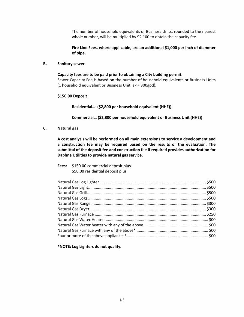
The number of household equivalents or Business Units, rounded to the nearest whole number, will be multiplied by $2,100 to obtain the capacity fee. Fire Line Fees, where applicable, are an additional $1,000 per inch of diameter of pipe.
B. Sanitary sewer
Capacity fees are to be paid prior to obtaining a City building permit. Sewer Capacity Fee is based on the number of household equivalents or Business Units (1 household equivalent or Business Unit is <= 300gpd). $150.00 Deposit
Residential… ($2,800 per household equivalent (HHE)) Commercial… ($2,800 per household equivalent or Business Unit (HHE))
C. Natural gas
A cost analysis will be performed on all main extensions to service a development and a construction fee may be required based on the results of the evaluation. The submittal of the deposit fee and construction fee if required provides authorization for Daphne Utilities to provide natural gas service. Fees: $150.00 commercial deposit plus
$50.00 residential deposit plus Natural Gas Log Lighter ................................................................................................. $500 Natural Gas Light........................................................................................................... $500 Natural Gas Grill ............................................................................................................ $500 Natural Gas Logs ........................................................................................................... $500 Natural Gas Range ........................................................................................................ $300 Natural Gas Dryer ......................................................................................................... $300 Natural Gas Furnace ..................................................................................................... $250 Natural Gas Water Heater .............................................................................................. $00 Natural Gas Water heater with any of the above ........................................................... $00 Natural Gas Furnace with any of the above* ................................................................. $00 Four or more of the above appliances* .......................................................................... $00
*NOTE: Log Lighters do not qualify.
I-4
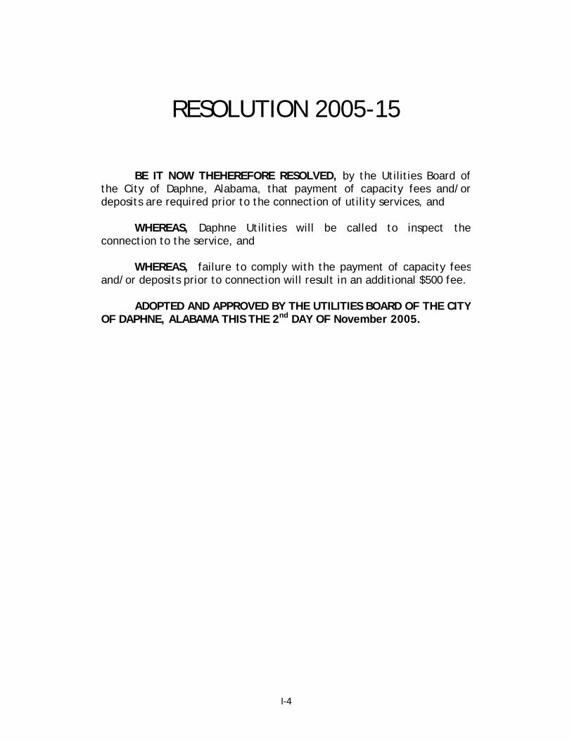
RESOLUTION 2005-15
BE IT NOW THEHEREFORE RESOLVED, by the Utilities Board of
the City of Daphne, Alabama, that payment of capacity fees and/or deposits are required prior to the connection of utility services, and
WHEREAS, Daphne Utilities will be called to inspect the
connection to the service, and WHEREAS, failure to comply with the payment of capacity fees
and/or deposits prior to connection will result in an additional $500 fee. ADOPTED AND APPROVED BY THE UTILITIES BOARD OF THE CITY
OF DAPHNE, ALABAMA THIS THE 2nd DAY OF November 2005.

I-5
APPLICATION FOR APPROVAL TO CONSTRUCT SANITARY SEWER AND/OR WATER DISTRIBUTION FACILITIES AND/OR GAS FACILITIES
I. GENERAL INFORMATION Applications for approval to construct wastewater facilities and/or water distribution facilities and/or gas facilities within the City of Daphne, its planning jurisdiction, or the Daphne Utilities service area shall be completed and submitted by the applicant to Daphne Utilities for approval. Approved applications will be required for Daphne Utilities to execute approvals for the Planning Commission for developments within the Daphne City limits and its planning jurisdiction. Applications shall include the following general information items in addition to completion of Items II through III of this application, design summary, submittal checklist, and conformance with the attached Division II - Design Criteria Provisions and standard specifications: 1. Project name and description of area served 2. Total area served, (Acres) 3. Estimated start of construction date 4. Estimated construction completion date 5. A map showing the design service area of the proposed utilities system(s) II. APPLICANT I, the undersigned, am fully aware that the statements made in this application for approval of wastewater and/or water facilities and/or gas facilities are true, correct and complete to the best of my knowledge. Mailing Address Signature of Applicant Telephone No. Name and Title Date Representing Owner/Company III. ENGINEER This is to certify that this application has been prepared under my direction and the plans and specifications for these wastewater and/or water facilities and/or gas facilities have been designed under my supervision and are in conformance with sound engineering practices and Daphne Utilities requirements. Mailing Address Signature of Engineer Company Name Name and Title Telephone Number Alabama Registration Number Date
I-6
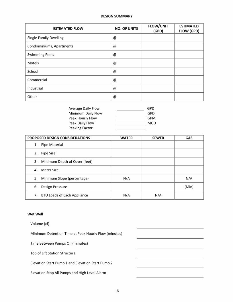
DESIGN SUMMARY
ESTIMATED FLOW NO. OF UNITS FLOW/UNIT (GPD)
ESTIMATED FLOW (GPD)
Single Family Dwelling @
Condominiums, Apartments @
Swimming Pools @
Motels @
School @
Commercial @
Industrial @
Other @
Average Daily Flow GPD Minimum Daily Flow GPD Peak Hourly Flow GPM Peak Daily Flow MGD Peaking Factor
PROPOSED DESIGN CONSIDERATIONS WATER SEWER GAS
1. Pipe Material
2. Pipe Size
3. Minimum Depth of Cover (feet)
4. Meter Size
5. Minimum Slope (percentage) N/A N/A
6. Design Pressure (Min)
7. BTU Loads of Each Appliance N/A N/A
Wet Well
Volume (cf)
Minimum Detention Time at Peak Hourly Flow (minutes)
Time Between Pumps On (minutes)
Top of Lift Station Structure
Elevation Start Pump 1 and Elevation Start Pump 2
Elevation Stop All Pumps and High Level Alarm

I-7
Pumps
Pump Manufacturer/Model No. and No. of Pumps
Static Head, Friction Head, Total Dynamic Head (feet)
Pump Capacity (GPM @ TDH; Horsepower)
Pump Controller Manufacturer/Model No.
Equipment Weight: Pump, Motor (lbs)
Suction Pressure (psig)
Twenty-five Year Flood Elevation
Electrical
Voltage, Phase
SCADA System
Generator Manufacturer/Model No.

I-8
SUBMITTAL CHECKLIST
The following are submittal requirements for Daphne Utilities for connection to Daphne Utilities’ utility lines and subsequent acceptance by Daphne Utilities for maintenance. Prior to the start of any project a pre construction meeting with representatives from Daphne Utilities is required before site work is performed.
POST-CONSTRUCTION SUBMITTALS Date Inspection Performed Record Drawings Submitted for Review Post Internal Video Inspection Submitted for Review Electronic GIS Copy of Record Drawings O/M Manuals Submitted Warranty Certification/ Bond Attached Here To Certification of Compliance ( Sample Format is Included) Letter of Certification from Manhole Supplier Two Copies of Internal Inspection Log A two year guarantee on materials and workmanship must be given in writing stating the beginning and ending date of the guarantee
PRE-CONSTRUCTION SUBMITTALS DATE Sealed Construction Plans (Pipe Material, Pipe Size, etc.) Site plan detailing area to be served Grading Plan in Area of Proposed Utility Work Calculations Pump curves Building construction plans Permanent easement descriptions submitted for review Flood verification certificates for facilities constructed within the 100 year flood plain
Statement that a pre construction conference will be held prior to starting any work on site and that Daphne Utilities will be notified of such meeting a minimum of forty-eight (48) working hours prior to date of meeting
Name, address, contact person and phone numbers of individuals responsible for decisions relating to design, ownership, capacity loads, capacity fees and construction must be furnished
Manufacturer certification that materials are suitable for the intend use of the project. Also, equipment and material submittals shall be reviewed and noted by Engineer for conformance with DU standards.
Statement that upon completion of the project and prior to a final “walk through”, record drawings, all material testing documentation, O/M manuals, and necessary warranties and bonds shall be provided. Also, Daphne Utilities shall receive a minimum of forty-eight (48) working hours notice of scheduled final “walk through”

I-9
Applicant or Applicant’s Engineer Certification of Compliance
This is to certify that the sewer infrastructure included in this application for acceptance by Daphne Utilities was constructed to meet all standards and current practices and includes all necessary submittal data and warranties. Also Daphne Utilities and their representatives have the right to use the attached electronic data for GIS purposes and utility business. Representative Signature Printed Representative Name Date (Note: Final acceptance is contingent upon approval by Daphne Utilities along with a completed application.)

II-1
STANDARD SPECIFICATIONS FOR CONSTRUCTING UTILITY FACILITIES
DIVISION II - DESIGN CRITERIA
A. GENERAL CRITERIA
1. Daphne Utilities Standard Specifications are intended for use in both new construction and modifications/improvements to existing infrastructure. Therefore, some portions are only applicable to one type of construction. An example is project documentation defined to be performed prior to the start of construction is intended for renovation projects to existing infrastructure around established areas and not intended for new construction in undeveloped areas. If uncertain if a section is applicable to a project, contact DU for verification prior to approval/construction.
2. Permanent easement descriptions dedicated solely to the Daphne Utilities, shall be provided for all areas not in dedicated public right of ways and listed in Daphne Utilities legal name. The minimum easement width shall be twenty (20) feet. If two of Daphne Utilities infrastructure (gas, sewer, or water) are installed within an easement, a minimum thirty (30) easement width shall be provided. Pumping stations for water or wastewater and gas compressor metering and regulating stations shall have a minimum area of forty feet by forty feet. However, final size shall be approved by Daphne Utilities to ensure proper access and maintenance in the sole opinion of Daphne Utilities.
3. If proposed development changes current state of existing infrastructure or necessitates modifications to Daphne Utilities existing infrastructure, such modifications shall be submitted to Daphne Utilities for approval during design. Modifications may be necessary due to proposed changes to existing surface conditions. If modifications are approved, all costs associated with such modifications shall not be incurred by Daphne Utilities but shall be borne by the Developer/Contractor including any necessary bypass pumping and all required testing such as Go-No-Go type mandrel, television inspection, bacteriological, and pressure testing.
4. Final acceptance of facilities submitted to Daphne Utilities for ownership and maintenance
shall be granted after a two year period provided the system is properly operating and the system is determined to continue to meet Daphne Utilities standards after the two-year period. Some materials require a longer warranty period that will be extended beyond the two (2) years. Any defects discovered during those warranty periods shall be replaced in-kind at no expense to Daphne Utilities.
5. Sanitary sewer system collection lines shall discharge directly into a treatment facility with a
current NPDES permit and available capacity. Temporary or permanent discharging of sanitary sewer into holding tanks or facilities for intermittent transporting to treatment facilities shall not be allowed within the Daphne service area.

II-2
6. Sanitary sewers shall be separated a minimum of 5 feet clear horizontal distance from any existing or proposed water main. Where sanitary sewers are required to cross water mains a minimum of 18 inches vertical distances between the outside of the mains shall be obtained. Sewer mains at water main crossings shall be constructed with ductile iron pipe with joints at least 9 feet from the crossing centerline. If these conditions cannot be obtained, additional design considerations approved by Daphne Utilities shall be incorporated to protect both lines and prevent cross contamination.
7. Sanitary sewer collection systems for multi-customers shall be gravity systems in
accordance with the standard specification parameters. Low pressure (multiple grinder pumps) systems shall not be acceptable within the City of Daphne, its planning jurisdiction, and Daphne Utilities service area unless otherwise approved by Daphne Utilities. Considerations will be given to areas where access for proper maintenance to sewer mains is impractical and cost prohibitive as determined solely by Daphne Utilities. When approved as an acceptable system in lieu of a gravity system, low pressure systems shall be constructed to provide flow conditions that will minimize the development of corrosive and odor conditions from H2S and to prevent the development of sewage BOD5
concentrations greater than 350 mg/l. 8. All new sanitary sewer and/or water distribution and/or gas facilities shall be constructed in
accordance with the Daphne Utilities standard specifications, the Alabama Department of Environmental Management (ADEM) standards and design criteria for water and sanitary sewer facilities, Ten States Standards, Environmental Protection Agency (EPA) Capacity Management, Operations and Maintenance (CMOM) provisions, and U.S. Department of Transportation, Transportation of Natural and Other Gas by Pipelines, Minimum Safety Standards. When conflicts between these standards occur, the more stringent of the requirements as determined solely by Daphne Utilities shall be required. Several of the standards required by Daphne Utilities are in accordance with the Recommended Standards for Water Works “Ten States Standard”.
9. The material preference under concrete pavement in dedicated right of ways is ductile iron. However, Daphne Utilities will consider other material selections that meet their standards based on specific field conditions.
10. For new developments, lateral locations shall be stamped in the curb with either an ‘S’ or
‘W’ as appropriate for the respective utility lateral. Also, as a general guidance in new development, the sewer lateral shall be located at one of the side lot lines of the parcel within the right of way and the water service line shall be located at the opposite side lot line in the right of way. The utility service location at the proposed side setback shall alternate per each parcel.
11. On all pressure sewer connections, the service lateral shall be in accordance with the
Standard Drawings and Daphne Utilities current practices including ball valves. Also, on all sewer connections where water service is not provided by Daphne Utilities, a locking valve, Sewur, shall be installed in accordance with current practices on the sewer service lateral.

II-3
12. To assure that manufacturers and suppliers are aware of the use to which their equipment and products will be subjected, the Contractor/Developer shall require the manufacturer or manufacturer’s representative to place the following certification on submittal data transmittals:
“This is to certify that we have examined the Plans and Specifications for this Project and have ascertained that this equipment or material is suitable for the purpose and use intended and meets Daphne Utilities current standards and practices. Authorized Signature”
13. Also, a certification shall be provided on all materials and equipment submittals that items
are in compliance with Daphne Utilities current standards and practices.
B. SANITARY SEWER SYSTEM DESIGN CRITERIA
DESIGN PARAMETER DESIGN VALUE
1. MINIMUM VELOCITY (ft/sec) IN GRAVITY LINES 2.1
2. DESIGN ROUGHNESS COEFFICIENT 0.013/130 (Manning’s n/Hazen-Williams C)
3. FLOW DEVELOPMENT a. Single family dwelling (GPCD) 125
4. MINIMUM PEAK HOURLY FLOW FACTOR 2.5
5. MINIMUM SLOPE (%)
a. 8” Sanitary Sewer Gravity Main 0.40 b. 10” Sanitary Sewer Gravity Main 0.28 c. 12” Sanitary Sewer Gravity Main 0.22 d. 16” Sanitary Sewer Gravity Main 0.13 e. 18” Sanitary Sewer Gravity Main 0.12 f. 20” Sanitary Sewer Gravity Main 0.09 g. 24” Sanitary Sewer Gravity Main 0.08 h. 30” Sanitary Sewer Gravity Main 0.07
6. MINIMUM DEPTH (inches from top of pipe to ground surface) 36
7. FORCE MAIN
a. Pipe material of construction (Ductile Iron or PVC) b. Minimum depth of cover (inches) 36 c. Velocity range (FPS) 3.5 - 5.5

II-4
DESIGN PARAMETER DESIGN VALUE
8. PUMPS a. Maximum pumping rate (GPM) Peak Hourly Flow b. Minimum number of pumps per station 2 c. Pump type Self Priming or Submersible
9. WET-WELL (Sizing to be Confirmed w/ Owner during Review)
a. Maximum detention time between pump run cycles (minutes) 15 b. Maximum detention time at peak flow (hours) 2 c. Minimum diameter (feet) 8 d. Grinder pump station minimum storage capacity (hours) 24 e. Grinder pump station wet well minimum diameter (feet) 6
10. SITE
a. Fence (chain link w/ slates or wood- Owner select during review) --- b. Roadway (paved, single lane, 12% maximum grade) --- c. Maximum landscaped slope (%) 20 d. Design flood event 100 years
11. BUILDING
a. Minimum height (feet) 8 b. Minimum unobstructed floor space (feet) 4 c. Ventilation requirements (air changes/hour):
1) Continuous duty 12 2) Intermittent 30
d. Water service line (inches) ¾ e. Interior lighting (48”, 4 bulb, 40W fixtures/100SF) (each) 2 f. Interior electrical receptacles (each):
1) 110 volt 4 2) 220 volt 2
12. ELECTRICAL
a. Incoming service: 1) Voltage (volts) 460/230 2) Phase 3
b. Control voltage (volts) 120
ADDITIONAL SANITARY SEWER REQUIREMENTS:
1. Gravity sanitary sewer collection mains shall be a minimum of eight (8) inches in diameter.
2. Where velocities will exceed 15 fps, special provisions shall be made to protect against displacement by erosion and impact.
3. Sanitary sewers shall be laid with uniform slope between manholes. 4. Sanitary sewers placed on 20 percent slopes or greater shall be anchored securely with an
approved method and spacing.

II-5
5. Curvilinear alignment of sanitary sewers shall not be utilized in construction. 6. Manholes shall be installed at a maximum of every 400 feet. Manholes shall also be
installed at: a) all changes in grade, size, or alignment; b) all intersections; and c) the end of each line.
7. Manholes shall be a minimum of 48 inches in diameter with minimum access diameter of 22
inches. 8. An approved drop connection shall be installed at each manhole where the sanitary sewer
pipe is 24 inches or more above the manhole invert. 9. Sanitary sewage system components and piping configurations shall comply with the
Daphne Utilities Standard Details for sewer systems. 10. All newly installed gravity sewer mains and segments of existing sanitary sewer where
connections are performed shall be videoed in accordance with DU standard specifications and practices.
11. In gravity systems where depths or at or exceed 20 feet, ductile iron pipe shall be utilized for
the entire length between manhole segments regardless of varying depths along the segment.
12. New sewage pumping stations shall be equipped with either a bypass pumps or emergency
standby power generator as determined by Daphne Utilities for each site. DU preference is bypass pumps; however, DU in their sole opinion, may allow for an emergency generator based on field location, size and operating and maintenance conditions. If the lift station pump motor is 5 HP or less and the station has a minimum of 12 hours of storage at average design flows, the Development/Owner may submit for consideration a request to Daphne Utilities for waiver of the bypass pump/generator equipment. The review will be on an individual basis and consider such factors as located in an environmentally sensitive area or difficult to access as determined solely by Daphne Utilities.
14. Supervisory Control and Data Acquisition (SCADA) systems in accordance with the SCADA
system currently in use by Daphne Utilities sewer system for monitoring operating conditions of the pump station from remote sites shall be installed at new sewage pumping stations.
15. An approved combination air-vacuum release valve unit shall be installed at all applicable areas along a force main and in accordance with the installed valve manufacturer’s recommendations.
16. Force main systems shall include clean out provisions for performing maintenance cleaning
of the force main system. The distance between cleanout accesses shall not exceed one mile. Access cleanouts shall allow for inserting and retrieval of approving maintenance “pigs” without excavating or “breaking into” the force main. Access cleanouts configuration and materials shall be approved by Daphne Utilities appropriate personnel prior to installing.

II-6
17. All gravity sanitary sewer laterals shall have an approved cleanout with backflow prevention measures near the home. If a house elevation is lower than the rim of any existing or proposed manhole, a check valve shall also be installed at the house.
18. All new developments shall purchase and have installed a minimum of one Manhole Monitored by Mission. If a development will be constructed in phases, each phase will be required to purchase and install one manhole monitor. The location of the manhole monitor will typically be installed in the lowest manhole rim along the hydraulic profile as determined by the design engineer of the proposed sewer system and discussed with Daphne Utilities. Based on the layout of the proposed sewer system and location to nearby sensitive areas, additional monitors may be required a Daphne Utilities’ discretion.
19. Low Pressure System Design Criteria (when permitted by Daphne Utilities):
a) All collector pipes shall be a minimum of two (2) inches in diameter. Force main cleanouts with valves shall be placed at dead end lines to allow for cleaning. Refer to drawing of cleanout in Standard Drawings herein.
b) The minimum allowable depth of cover is thirty (30) inches.
c) A Hazen Williams Coefficient of 130 to 140 shall be used for hydraulic analyses.
d) For design purposes, a velocity of 3 to 5 fps shall be obtained at least once a day.
e) The design conditions of the pump shall be in accordance with the pump manufacturer’s guidelines and recommendations.
f) All systems shall have a quick disconnect, a high level alarm, and an
external/remote control panel. The alarm shall have a light and auditory device.
g) Force mains shall not be constructed under pavement or concrete.
h) Air release valves, shall be located at high points in the line and shall be properly sized for the design operating conditions. Air release valves shall be either brass or stainless steel. Galvanized steel valves will not be accepted.
i) All sewer service laterals shall be per the current practices of DU. Developer to
confirm detail in Standard Drawings is current prior to ordering materials/installation.
C. WATER SYSTEM DESIGN CRITERIA
1. Pressure: All water mains, including those not designed to provide fire protection, shall be
sized after a hydraulic analysis based on flow demands and pressure requirements. The system shall be designed to maintain a minimum pressure of 20 psi (140 kPa) at ground level at all points in the distribution system under all conditions of flow. The normal working pressure in the distribution system should be approximately 60 to 120 psi and not less than 35 psi.

II-7
2. Diameter: The minimum size of water mains for providing fire protection and serving fire hydrants shall be six (6) inch diameter. Larger size mains will be required if necessary to allow the withdrawal of the required fire flow while maintaining a minimum residual pressure of 20 psi.
3. Fire Protection: When fire protection is to be provided, system design should be such that
fire flows and facilities are in accordance with the requirements of the State Insurance Services Office.
4. Hydrants: Water mains not designed to carry fire-flows shall not have fire hydrants
connected to them. All fire hydrants shall have isolation valves. 5. Dead Ends:
a. In order to provide increased reliability of service and reduce head loss, dead ends
shall not be permitted except for new construction of a single street with a cul-de-sac. All new subdivisions shall be looped feed to provide adequate fire protection.
b. Where dead-end mains occur, they shall be provided with a fire hydrant if flow and
pressure are sufficient to meet at least minimum system hydraulic requirements, or with an approved flushing hydrant or blow-off for flushing purposes. In this case flow and pressure calculations must be provided to Daphne Utilities. Flushing devices shall be sized to provide flows which will provide a velocity of at least 2.5 feet per second in the water main being flushed. No flushing device shall be directly connected to any sewer system.
6. New water pumping stations shall be equipped with either emergency standby power
generator or bypass pumps as determined by Daphne Utilities for each site. Supervisory Control and Data Acquisition (SCADA) systems in accordance with the SCADA systems currently in use by Daphne Utilities water system for monitoring operating conditions of the pump station from remote sites shall be installed at new water pumping stations.
D. GAS SYSTEM DESIGN CRITERIA
1. All gas main work shall conform to the applicable requirements of the U.S. Department of Transportation, Part 192, Transportation of Natural and Other Gas by Pipeline: Minimum Federal Safety Standards, most recent edition and current building code adopted by the City of Daphne along with the requirements of Daphne Utilities. Any Contractor employee who will perform gas work shall meet the “Qualifications of Pipeline Personnel - Subpart N”. Contractor’s employees who fuse plastic pipe shall be certified in fusion approved by Alabama Public Service Commission Office of Pipeline Safety. Contractor’s employees who connect to hot gas mains or install live taps shall be qualified in that covered task per Daphne Utilities Operator Qualification Program. Documentation of compliance of these requirements shall be provided to Daphne Utilities.
2. A construction form to the Public Service Commission Office of Pipeline Safety shall be
submitted by the Contractor prior to beginning construction with a copy to Daphne Utilities. 3. Bushings shall not be permitted on any gas piping. CST piping shall not be permitted to be installed in any area except within six feet of an appliance connection.

II-8
4. Valves shall be required on every appliance, including fireplaces with a built in valve. A log lighter valve should be added a minimum of two (2) feet from the unit for external accessibility. If this is not feasible because of the location of the fireplace the valve can be placed in the attic.
5. A pressure test of new and old fuel lines shall be inspected by the City of Daphne Building
Inspection Department or authorized agent of the City, i.e. Daphne Utilities. Twenty (20) pounds of pressure shall be maintained for a minimum of one (1) hour limit. The inspection authority shall be given proper notice, as detailed herein, of a request for inspection.
6. A regulator shall be installed at each appliance which is located on a pound fuel line system. A spilt gas system shall not be permitted. A spilt gas system is defined as installing a second regulator outside of the house and downstream of regulator installed by the Utility.
7. Shrubs or trees shall not be within two (2) feet of a gas meter.
8. No gas meter shall be installed inside a fenced area that prohibits access from reading or
maintenance of the meter. 9. Per Part 192 Minimum Federal Pipeline Safety Standards, if the meter service valve is in the
off position, it shall be locked off until it is to be turned on and used following proper inspections.
10. If any appliance or fuel line component is found to be unsafe, the appliance shall be red
tagged and the customer shall be given a time frame to have it repaired. If the appliance or fuel line component cannot be isolated, the meter shall be locked off until such repair is made.
11. If a system has a natural gas leak or a carbon monoxide reading of 35 PPM or greater, the
system shall be locked off until repaired. 12. If the City Building Inspection Department or authorized agent of the City determines that
any part of the venting system is not within code, the system shall be locked off until repaired/corrected.
13. If a leak is found on the customer’s fuel line system and if the component cannot be isolated, the meter shall be locked off until repaired and a pressure test is passed. Refer to item numbers five and eleven for further explanation.
14. If at any time a customer’s fuel line system is locked off due to a leak or changes to the
customer’s fuel line system, it must be repaired to meet the current gas code adopted by the City of Daphne and the standards as set forth herein and as established by the Daphne Utilities Gas Department.
15. A minimum of one (1) inch diameter galvanized or black iron fuel piping shall be installed
from the connection with the meter through the wall of the structure up to the attic. After the fuel piping enters the attic and is no longer within the wall of the structure, the diameter of the fuel piping may be reduced. At this reduction point, the piping shall be at an accessible location.
II-9
16. For island stove installations, a four (4) inch casing shall be required to be installed in the slab from the wall to the stove island. There shall be no joints in the fuel piping from the attic to the stove island. Also, a valve shall be installed above the floor under the stove island unit.
17. For commercial buildings, exposed external fuel piping on external walls shall be painted
yellow and secured. 18. A flex hose, copper, or corrugated stainless steel flex tubing with yellow coated polymer
jacket may be used from the log lighter valve to the fireplace. 19. Daphne Utilities shall only be responsible for setting the meter. The Customer’s
representative (i.e., plumber) shall be responsible for connecting the meter to the establishment.
20. Prior to the meter being installed, the customer or customer’s representative shall provide
the total BTU input to the system, type of fuel system desired, and proposed gas appliances. Daphne Utilities has an “Inspection Load” Form to assist with providing the needed information.
21. The customer’s representation shall clearly indicate with taping on the fuel system piping
located on the outside of the structure near the proposed meter installation as to the type of fuel system desired. Blue tape shall denote an ounce fueling system and red tape shall denote a pound fueling system.
22. All piping installed for future supply pipe shall be connected to the supply line and pressure
tested at the time of installation. Also, the future connection location shall be valved and capped.
23. All gas inspections shall be scheduled with City of Daphne Building Inspection Department
or the authorized agent a minimum of twenty-four (24) hours prior to the requested inspection date. It shall be the customer’s or the customer’s appointed representative (i.e. plumber) responsibility to schedule such inspections at the appropriate time during construction.
24. Rough piping inspections shall be scheduled and performed after all piping has been
installed and before any such piping has been covered or concealed or any fixtures or gas appliances have been connected. This inspection shall also include a pressure test.
25. Final inspections shall be scheduled and performed at time of requested turn in for service. 26. If pressure test, piping, and installation are not inspected and approved by the Building
Inspection Department or authorized agent, service shall not be turned on to the facility.

II-10
E. SUMMARY AT A GLANCE OF KEY COMPONENTS
This list is not intended to note all requirements set forth in these specifications. It is the owner’s responsibility to ensure that all work conforms to Daphne Utilities standards and requirements. Refer to Appendix for list of acceptable products and manufacturers.
Water Sewer Gas Comments Pipe Material
PVC C900
SDR 18 or heavier for 4” or greater
SDR 35 - Gravity C900 - Force Main 4” or
greater Not Accepted
Tracer Wire and Marking Tape Required
DI Min. 150 pressure Class 52 Not Accepted
Polyethylene Sheath Required unless testing confirms otherwise
HDPE SDR 11 DIPS OD SDR 11 DIPS OD SDR 11 Tracer Wire and Marking Tape Required
Pipe Size - Minimum (Inches)
6 8 - Gravity
6 - Force Main 2 - LPFM
2
Fittings Material DI DI HDPE
Meters
5/8 - 1” -Sensus Metering
Systems SRII 1.5” - 8” Sensus Metering Systems
Omni
N/A Or Current Daphne Utilities’ Standards
Size
1” to 2” - Rigid Copper
3” to 4” - DI or PVC C900 with
Mechanical Joint Fittings
N/A
Bypass Meter 1 ½” and Larger Bypass
Required N/A
Valves
Resilient Seated Gate Valve Mueller, American, Kennedy, Clow Gaskets, Bolts, and Nuts shall be furnished
Check Valve Mueller, Clow, American, DeZurick
Air & Vacuum Valve Assembly
ARI, APCO, Val-Matic
Tapping Valve & Sleeve JCM, Romac, Mueller Stainless Steel

II-11
Water Sewer Gas Comments
Back Flow Preventor Ford Cat No.
HHS331-323 & Mueller H14242
Thrust Restraint Required at Bends and Along Pipe Segments as Necessitated by Design Calculations for
Thrust Restraint at Fittings N/A
Both Concrete Thrust Blocks and Mechanical Joint Restraints Are Required
Pigging All FM All 4” Mains and Larger
Testing/Inspection Chlorination and Hydrostatic Testing
Internal Video Inspection, Go-no-go Mandrel, Pneumatic
Testing
Pressure Tests, Holiday Detector
Tests
Water
• Fire Hydrants Installed Every 500 Feet • Gate valves shall be located a maximum of 2 feet from hydrant.
Sewer • Minimum Manhole Size - 48” • Minimum Manhole Depth - 6 Feet • Inflow Dish - Required at low areas unable to have an elevated manhole and/or as directed by DU,
Approved manufacturer is Rainstopper. • Chimney Seals - Shall be installed in new or existing manholes to stop infiltration • Testing for Lift Stations - Vacuum Testing • Lining - Required for manholes that have a discharge from a force main and all lift station wet wells • Materials Inside Wet Well - Only PVC and Stainless Steel used in wet well • RTU - Mission 800 & Manhole Monitor by Mission • “Man Down” Button Required at Lift Station Control Panel • Automatic Transfer Switch required for bypass pumps/generators • Back up floats shall be provided in Lift Station • Hardware - Stainless Steel • Operation and Maintenance Manuals Required for Lift Stations • Testing for Lift Stations - Operational Acceptance Test, Factory System Test, Conductor Insulation
Resistance Test, Ground Rod Resistance Test, and Demonstration Test • The standard for bypass pumps/generators shall be natural gas unless a waiver is requested and
granted by Daphne Utilities. • Exhaust Silencer: Critical type silencer, with muffler companion flanges and flexible stainless-steel
exhaust fitting, suitable for horizontal orientation, sized in accordance with engine manufacturer’s instructions
• Testing for Generator - Factory Test, Functional Test, Field Quality Control Test • Manufacturers for Generator - Generac Power Systems, Katolight Corporation, Kohler Power Systems,
Cummings, Caterpillar • Manufacturers for Bypass Pumps - Godwin Pumps, Cornell Pumps, Pioneer
Gas • Conformance with USDOT Part 192
END OF SECTION

1-1
STANDARD SPECIFICATIONS FOR CONSTRUCTING WATER DISTRIBUTION FACILITIES
DIVISION III – CONSTRUCTION SPECIFICATIONS
SECTION 1
GENERAL SPECIFICATIONS FOR WATER MAINS 1.01 SCOPE
These general and detailed specifications form a part of the Contract documents and shall govern the handling and installation of water piping, valves, hydrants and accessories described herein, and as shown on the accompanying plans. Existing water distribution facilities are owned and operated by Daphne Utilities, hereinafter referred to as “Owner”. The construction methods employed in the placement of the water main and appurtenances shall be in accordance with current codes, practices and specifications of the Owner.
1.02 WORK INCLUDED
All labor, equipment, and material necessary to complete the work as stipulated herein. The Contractor shall clear and grub as necessary, remove as much of the pavement as may be necessary; excavate the trenches and pits to the required dimensions; excavate the bell holes; sheet, brace and support the adjoining ground or structures where necessary; construct and maintain all bridges required for traffic control; handle all drainage or groundwater; guard the site, unload, haul, distribute, and lay the pipe fittings and accessories; rearrange the branch connections to transmission mains, or rearrange other conduits, ducts or pipes where necessary; connect new mains to existing mains; connect existing services to new mains; replace all damaged drains, mains or other structures; backfill the trench; restore the roadway surface; remove surplus excavated material; clean the site of the work; chlorinate the completed pipeline; have samples checked and approved for bacteriological analysis by the State Board of Health or other approved regulatory agency, perform hydrostatic testing and flushing the completed pipeline; and maintain the street or other surface over the trenches.
1.03 SCHEDULE OF OPERATIONS
The Contractor shall prepare and submit to the Owner/Engineer for approval by the Owner/Engineer, prior to beginning construction, a schedule of his proposed operations outlining his sequence of pipe installation, connections to existing mains and placement of new water mains in service.
1.04 MATERIALS
A. Ductile Iron Pipe: Ductile iron pipe for water lines shall meet requirements of AWWA Specification C151 with mechanical joint or push-on joint unless specifically shown otherwise on the plans. Working pressure shall be a minimum of 150 psi.

1-2
The interior of all pipe shall be cement-mortar lined as specified in AWWA Specification C104 and the exterior shall receive an approved bituminous coating. All gaskets, bolts and lubricants shall be furnished.
Ductile iron pipe shall be centrifugally cast with minimum wall thickness in accordance
with AWWA C151, latest revision, except where shown otherwise on the project plans or in the proposal.
Unless otherwise indicated by soil testing, or as directed by the Owner or the Engineer,
polyethylene encasement shall be installed on all ductile iron pipe and appurtenances at all locations and shall conform to AWWA C105, latest revision, “Standard for Polyethylene Encasement for Ductile Iron Piping for Water and Other Liquids.” Cost for any soil testing by an independent laboratory to determine soil characteristics shall be paid for by the Contractor. Refer to “Polyethylene Sheath” included herein for additional details.
If it is necessary to cut ductile iron pipe, in no case shall it be cut by burning, but shall be
cut by saw, cutter, abrasive wheel or other approved means. The pressure rating, metal thickness, net weight of pipe without lining, length of pipe,
name of manufacturer and letter “DI” shall be clearly marked on each length of pipe. There is a preference for domestic pipe.
1. Flexible Joint Ductile Iron Pipe: Flexible joint pipe shall meet the requirements
of AWWA Specification C151 and may be of the bolted or boltless type suitable for 150 psi working pressure. If bolted type pipe is used, all bolts and nuts shall be Corten Steel. The interior shall be cement-mortar lined as specified in AWWA Specification C104. The exterior of all pipe and fittings shall receive an approved bituminous coating, except the ball and machined surfaces, which shall receive a protective coating as recommended by the manufacturer. All ball joint pipe shall be assembled, lubricated and installed in strict conformance with the pipe manufacturer’s recommendations.
2. Ductile Iron Fittings: Ductile iron shall be mechanical joint except where noted
otherwise on the plans. Fittings shall be suitable for use at 250 psi working pressure and shall conform to AWWA Specification C110. Fittings shall be cement-mortar lined and the exterior coated with an approved bituminous coating, in accordance with AWWA Specification C104. At the Contractor’s option, compact ductile iron fittings meeting AWWA C153 may be furnished.
3. Positive Restrained Joint Pipe and Fittings: Positive restrained joint pipe and
fittings may be used in lieu of friction restrained fittings. Positive restrained joint pipe and fittings shall be either mechanical joint or push-on joint and shall be manufacturer’s standard restrained joint. The joint shall achieve restraint by means of a positive factory made, metal-to-metal contact and shall allow full deflection of the joint when made up.

1-3
4. Friction Restrained Fittings: The following type friction restrained fittings may be used in lieu of positive restraint:
a. Locked mechanical joint retainer glands of adequate strength to prevent
movement may be used to supplement concrete backing. Locked mechanical joint retainer glands shall be ductile iron retainer glands equipped with hardened cupped end set screws of a type, which insure proper actuating of the restrained devices. Set Screw type shall be used on ductile iron pipe.
b. Friction mechanical joint restraint may be used in lieu of locked
mechanical joint retainer glands. Mechanical joint restraint shall be incorporated in the design of the follower gland and shall include a restraining mechanism which, when actuated, imports multiple wedging action against the pipe, increasing its resistance as the pressure increases. Flexibility of the joint shall be maintained after burial. Restraint shall be epoxy coated. Joint restraint shall be provided by an approved Manufacturer listed in the Appendix or Owner approved equal.
c. A gasket system utilizing stainless steel locking segments molded into
the gasket may be used in lieu of mechanical joint retainer glands to achieve joint restraint for ductile iron push-on pipe in sizes of 4 inches through 12 inches. System shall be provided by an approved Manufacturer listed in the Appendix or Owner approved equal.
5. Polyethylene Sheath: Unless otherwise indicated by soil testing, polyethylene
sheath shall be installed on all ductile iron pipe and appurtenances and shall conform to AWWA C105, latest revision, “Standard for Polyethylene Encasement for Ductile Iron Piping for Water and Other Liquids” and shall be either 4 mil HDCL or 8 mil LLD. The installation shall be method A. Backfill shall be as specified elsewhere in these specifications.
Polyethylene encasement shall not be exposed to sunlight longer than 7 days.
Contractor shall furnish written certification, accompanied by a copy of test results, that the pipe and pipe material has been sampled, tested, and inspected as required. These certifications and test results shall be submitted, in five complete copies, to the Owner/Engineer for review and the pipe manufacturer shall retain duplicate copies of all test results in permanent files to be made available upon request.
Care shall be taken not to damage the polyethylene sheath during the backfill operation. Any polyethylene sheath, which is damaged, shall be replaced or repaired by the Contractor at no additional expense to the Owner.
1-4
B. PVC Plastic Pipe for Water Lines:
1. Polyvinyl chloride (PVC) plastic pipe in sizes 4 inch and greater in diameter shall conform to the requirements of AWWA C900, “Standard for Pressure Pipe with Cast Iron Pipe Outside Diameter.” Pipe shall be a minimum Class 150 (UL 235) with a Standard Dimension Ratio of 18 or heavier. Pipe joints shall be integral bell and spigot type with rubber ring sealing gasket. Lubricant for making joints shall be non-toxic, and shall be as recommended by the pipe manufacturer. The pipe bell shall be designed to be at least as strong as the pipe wall. Standard lengths shall be 20 feet except that 15 percent of total footage for a particular project may be random lengths of not less than 10 feet each. Each piece of pipe shall be tested by the manufacturer to 600 psi for a minimum of 5 seconds. The bell shall be tested with the pipe. Ductile iron fittings conforming to the requirements of these specifications shall be used with PVC pipe.
Contractor shall furnish written certification, accompanied by a copy of test results, that the pipe and pipe material has been sampled, tested, and inspected as required in AWWA C900. These certifications and test results shall be submitted, in five (5) complete copies, to the Engineer for review and the pipe manufacturer shall retain duplicate copes of all test results in permanent files to be made available upon request. The tests and certifications shall be of such frequency as to be representative of the entire Project.
2. Polyvinyl chloride (PVC) plastic pipe for diameter sizes less than 4-inch shall
conform to the requirements of ASTM D-2241 and shall be minimum SDR 21 Class 200 manufactured from a Type I, Grade I polyvinyl chloride compound with a cell classification of 12454 per ASTM D1784. Pipe joints shall be integral bell and spigot type with rubber ring sealing gasket. Lubricant for making joints shall be non-toxic, and shall be as recommended by the pipe manufacturer. The pipe bell shall be designed to be at least as strong as the pipe wall. Bells shall be manufactured so that o-rings gaskets are square to the barrel of the pipe. Standard lengths shall be 20 feet except that 15 percent of total footage for a particular project may be random lengths of not less than 10 feet each. Ductile iron fittings conforming to the requirements of these specifications shall be used with PVC pipe. Fittings shall be mechanical joint and shall be provided with a transition gasket specifically designed to accommodate the outside diameter of the pipe.
For all PVC pipe, the Contractor shall furnish written certification, accompanied
by a copy of test results, that the pipe and pipe material has been sampled, tested and inspected as required in ASTM D 2241. These certifications and test results shall be submitted, in five complete copies, to the Owner/Engineer for review and the pipe manufacturer shall retain duplicate copies of all test results in permanent files to be made available upon request. The tests and certifications shall be of such frequency as to be representative of the entire Project.

1-5
3. Markings of PVC Piping: Marking on the pipe shall include the following, spaced
at intervals of not more than 5 feet:
a. Nominal pipe size and OD bore b. Type of plastic material c. Dimension Ratio d. Pressure Class e. Manufacturer’s name or trademark f. National Sanitation Foundation (NSF) seal of approval for drinking water
4. Tracer Wire for PVC Pipe: All PVC pipe shall be marked using a tracer wire buried 6 inches above the top of the pipe. The tracer wire shall be a 12 gauge except in directional drill applications wire shall be 8 gauge insulated copper wire and shall have blue coating. The pipe trench shall be backfilled to approximately 6 inches over the top of the pipe then the tracer wire shall be placed over the top of the pipe. Backfill shall be carefully placed to a depth of 6 inches by hand to assure that the wire is secured in place over the pipe. It is the intent to provide a means to locate PVC pipe using standard pipe locating equipment. The wire shall be carried up through every valve boxes and terminated at least 2 feet above the ground line to permit connecting of locating equipment. Excess wire at valve boxes shall be neatly rolled and stored in the valve box for easy accessibility.
If valve and valve boxes are not located within 500 feet, a valve box shall be
installed for the purpose stated herein.
5. Marking Tape for PVC Pipe: All PVC pipe shall be marked using a nonmetallic tape buried at least 15 inches above the top of the pipe. Water mains shall be marked with blue tape. Tape shall be 3 inches wide minimum made of an inert plastic film resistant to alkalis, acids or other destructive chemical components likely to be encountered in soils. After the tracer wire has been placed, the pipe trench shall be backfilled to approximately 15 inches over the top of the pipe then the nonmetallic tape shall be placed flat over the top of pipe. Backfill shall be carefully placed to a depth of six inches by hand to assure that the tape is secured in place over the pipe. It is the intent to provide a visible marker in the event of excavation near a water line.
6. Fittings for PVC Pipe: Fittings for PVC pipe shall be ductile iron fittings as
specified for ductile iron pipe.
7. Restrained Joint Fittings: Where restrained joint fittings are required with PVC water pipe mechanical joint restraint fittings made specifically for PVC pipe connecting to ductile iron fittings are acceptable. Where PVC pipe is connecting to a PVC fitting, proper fittings are to be provided. Restraints shall be epoxy coated. Restraints shall be provided by an approved Manufacturer listed in the Appendix or Owner approved equal. If requested, mill test report shall be provided.
1-6
8. All water PVC pipe shall be blue in color. White pipe may be substituted
provided a stripe, applied by the pipe manufacturer, further defined below is applied to the surface of the pipe 180 degrees from the normal pipe markings. The pipe shall be placed in the trench with the stripe visible from the top of the pipe trench. For pipe sizes four inches in diameter and smaller, a one inch wide continuous blue stripe shall be applied. For pipe diameters greater than four inches, a three-inch wide continuous blue solid stripe shall be applied.
C. High Density Polyethylene (HDPE):
Only when prior approval is granted by the Owner HDPE may be used for potable water installations. The Owner reserves the right, in their sole opinion, to refuse the use of any material within their system. Pipe shall be made from high density polyethylene resin compound which meets ASTM D3350, PE 4710, SDR 11 DIPS OD, unless pipe size is less than three inches than IPS may be utilized. Pipe shall be on the Owner’s list of materials and approved manufacturers. Dimensions and workmanship shall conform to ASTM F714. Fittings for HDPE pipe shall be made of ductile iron conforming to the section above for ductile iron. Adapters or transition coupling shall be utilized to transition between HPDE and DI. The adapter shall be mechanical joint, threaded, or flanged depending on the application and suitable for connection to the DI Fitting.
Polyethylene pipe shall be the nominal pipe size and dimension ratio shown on the plans, or in the proposal. Unless field conditions dictate a heavier wall thickness, SDR 11 shall be used. Installation shall be in accordance with ASTM D2321 or as modified herein. For 4 inches in diameter and larger, pipe shall conform to DIPS. For 2 inches in diameter, pipe shall conform to SDR 7, CTS. Pipe shall be have a manufacturer applied blue stripe or be solid blue for water application. Solid black pipe shall not be permitted. Shipping lengths of pipe shall be assembled into one continuous length at the job site by thermal butt-fusion. Fusion machine and fusion machine operator shall be approved by pipe manufacturer. The resultant joint shall be as strong as the intervening lengths. Jointing of pipe and installation of outlets shall be in accordance with the pipe manufacturer's written recommendations. The pipe manufacturer shall provide the services of a trained representative to instruct the Contractor's forces in the proper techniques for jointing of pipe and the installation of outlets or other items. Contractors shall provide written certification from the manufacturer that the personnel performing the joint welding has received proper training for the welding of the manufacturers piping material. Data logger shall be used for all machine welding of pipe and data from logger provided to Owner/Engineer. Hand written data from the logger will shall not be accepted. Installation of polyethylene pipe in areas where flotation is probable whether on land or a subaqueous location installation shall conform with manufacturer's recommendation.

1-7
Polyethylene pipe shall not be crimped in any way during construction. Fabricated polyethylene bends shall be manufactured by pipe manufacturer. SDR of fabricated polyethylene bends shall be equal to SDR of connecting pipe. Deflection of polyethylene pipe after installation and backfilling shall not exceed 5 percent. Tracer wire and marker in accordance with PVC pipe section shall be provided for HDPE pipe.
D. Fusible PVC: Fusible PVC may be submitted for consideration by the Owner in areas of transmission mains for directional drills provided the material meets all standards for C 900 PVC and is constructed in accordance with all manufacturer.
E. Gate Valves:
1. Resilient Seated Gate Valves: All valves shall be non-rising stem for underground
directional burial service and shall close when the operating nut is turned in clockwise rotation. Valves shall be in accordance with and meet the requirements of AWWA C515. O-ring seals shall be provided and the valve shall be a compression resilient seated gate valve. Disc shall be SBR coated. Valve body shall be fusion-epoxy bonded inside and out. Valves shall be furnished complete with necessary gaskets, stainless steel bolts and nuts as needed for mechanical joint ends.
Mechanical joints and accessories shall comply with the latest published AWWA C111. Gaskets shall be of best grade quality of a type suitable for potable water service.
a. Valves (12 Inches and Smaller): Each valve shall have mechanical joint
bell ends. Valve shall be installed with the operating stem in the vertical position. Valve stem shall be furnished with 2 inch square water works nut.
b. Valves (24 Inches and Larger): Ductile iron resilient seated gate valves
produced by manufacturers on the Daphne Utilities approved list, meeting or exceeding all of the requirements and recommendations of AWWA C515, may be used on valves twenty four inches and larger in diameter provided they meet the additional criteria listed in this section.
F. Butterfly Valves:
1. General: Butterfly valves shall only be installed with prior approval by the Owner. These valves are not intended for installation on main distribution lines or service lines. If approved by the Owner, butterfly valves shall be rubber
1-8
seated for 150 psi minimum working pressure and line velocities up to 16 fps. The bodies of all valves shall be cast iron construction of ASTM A126, Class B, or ASTM A48, Class 40. Valves shall be on Daphne Utilities’ list of materials and approved manufacturers. Underground valves shall be provided with operators with noncorrosion type of construction for input shaft, seals, bushings and bolting. Operators shall be totally enclosed and permanently lubricated for direct burial of the valves and frequent submergence in water up to 20 feet of head. The operators shall open the valves on a counterclockwise rotation of the nut wrench which shall be AWWA 2 inch square cast iron. The valve ends shall be mechanical joint in accordance with AWWA C111, except where indicated otherwise on the plans or in the proposal.
Except as modified herein, the butterfly valves and operators shall meet, or
exceed, the applicable requirements of the “Specifications for Rubber Seated Butterfly Valves,” AWWA C504, for Class 150B.
2. Stuffing Boxes: All butterfly valves shall be provided with O-ring seals,
nonadjustable stuffing boxes, and shall be self-sealing or self-adjusting type, which can be replaced without the necessity of removing the valve or the valve shaft from its pipeline location.
3. Valve Shafts: The valve will be installed with the valve shaft in a horizontal
position. The shaft shall be of 18-8 stainless steel, Type 304. A machined, one piece, high tensile steel hexagonal shaft fitting on a matching opening through the valve disc, completely sealed from the pipeline contents with Type 304 stainless steel bushings, will be acceptable. Valve disc shall be keyed or pinned securely to the valve shaft. Pins, wedges and accessories shall be 18-8 stainless steel, Type 304 or 316.
4. Valve Discs: The material for valve discs may be ductile iron ASTM A536 or
ASTM A48, Class 40, cast iron. 5. Valve Seats: The mating seat surfaces shall be 18-8 stainless steel on natural
rubber.
G. Tapping Valves and Sleeves: Tapping valves shall meet the requirements set forth for gate valves as described in these Specifications and shall be on the Daphne Utilities list of materials and approved manufacturers. Tapping sleeves shall be stainless steel with carbon steel flanges. Tapping sleeves being 12” x 12” and smaller shall have a minimum working pressure of 200 psi and larger sleeves shall have a working pressure of 150 psi. All tapping sleeves shall be stainless steel with full wraps. Tapping valves and sleeves are to be used for making connections to existing mains. Daphne Utilities shall be notified forty-eight (48) hours prior to any tapping of an existing water main.
H. Fire Hydrants:
1. All hydrant manufacturers shall be on Daphne Utilities’ list of approved materials and manufacturers, or an Owner/Engineer approved equal. All
1-9
hydrants shall meet or exceed AWWA C-502, latest revision, shall be the traffic-model design, and shall be rated at 200 psi working pressure, 400 psi hydrostatic test pressure. Size of hydrant valve shall be 5¼ inches minimum and of a compression type that closes with the pressure. Hydrants shall be located at a maximum of every 500 feet. All operating parts, including the drain ring, operating nut, hold-down nut, upper valve plate, seat ring, drain lever, and nozzles shall be made of bronze, in compliance with AWWA C-502, Section 2.2.501.
a. The bonnet assembly shall provide for an oil or grease reservoir and
lubricating system that lubricates all stem threads and bearing surfaces each time the hydrant is operated. The reservoir shall be completely sealed from the waterway and all external contaminants by two (2) O-ring stem seals. Hydrants shall be factory prefilled with a lubricant suitable for a working range of -60 degrees F to +150 degrees F and shall comply with USDA Safety and Health Regulations. Material Safety Data Sheets shall be made available if requested.
b. Hydrants shall be provided with two (2) 2½ “bronze hose nozzles and
one (1) 4½ “bronze pumper nozzle. All nozzle threads shall be National Standard Fire Hose Coupling thread. Nozzle caps shall be cast or ductile iron and provided with gaskets and chains.
c. Hydrants shall have a 6” mechanical joint inlet, less accessories, with the
interior of the hydrant shoe fully fusion bonded epoxy coated with at least 4 mils in accordance with AWWA C-550 and the exterior of the hydrant shoe coated with at least 8 mils of asphaltic coating or epoxy coated to the same specification as the interior.
d. The exterior of the lower barrel shall be coated with 4 to 8 mils of
asphaltic coating in compliance with ANSI/AWWA C110/A21.10. The interior of the lower barrel shall be seal coated in accordance with the requirements of Seal Coating in ANSI/AWWA C104/A21.4 to a thickness of no less than 4 mils.
e. Flanges of the hydrant lower barrel shall be integral cast with the barrel,
screwed on, or of a connection type approved by the Owner. f. The shoe of the hydrant shall be made of ductile iron. The lower barrel
shall be made of cast iron only. Shoes shall have the letters “DI” or “Ductile” cast, stamped, or stenciled (painted) on them.
g. Hydrants shall utilize three-quarter inch (¾”) bolts meeting ASTM A-307
Grade B, zinc coated by the hot dip process, in accordance with the requirements of Class C of Specification A 153, to secure the lower barrel to the hydrant shoe or Type 316 Stainless Steel bolts must be used if the bolts are less than ¾” in diameter.
1-10
h. Hydrants shall be of the three-way design with the upper barrel capable of full 360-degree rotation by any degree.
i. Gate valves shall be located a maximum of two (2) feet from hydrants. j. Hydrants shall have a 1½ “ pentagon, one piece operating nut and open
left. Protection from weather shall be accomplished by one or both of the following methods:
i. The weather cap shall be an integral part of the fire hydrant
operating nut.
ii. An exterior rubber seal to prevent water entry and a redundant interior rubber seal for additional protection. (2 separate seals)
k. Hydrants shall allow for easy installation of barrels or extensions at the
hydrant shoe or groundline without having to shut off the water main. l. Design, materials and workmanship shall be similar and equal to the
latest stock pattern produced by the manufacturer and that hydrant shall be of the same general type as the hydrants in the existing system.
m. Hydrants shall be furnished for a bury of 3’ 6” except where otherwise
required in the field and/or called for by the plans. Hydrant shall be equipped with traffic break away feature.
n. The inside diameter of hydrant barrel shall be 6.125 inches or greater.
Hydrants with barrels less than 7 inches shall meet AWWA C-502 minimum wall thickness requirements for a 7-inch inside diameter barrel.
o. Friction losses through the hydrant shall not exceed 7.6 psi at 1500 gpm
or 3.0 psi at 1000 gpm through the pumper nozzle, and 1.25 psi at 500 gpm through two (2) hose nozzles when tested simultaneously as outlined by AWWA C-502. Flow test results indicating the friction losses through the hydrant shall not be older than 12 months from the date said results are requested by Daphne Utilities. Flow tests must be conducted by an independent lab. Each manufacturer must provide written certification, if requested, that their hydrants meet all of the Daphne Utilities’ hydrant specifications.
p. Hydrants shall be painted in accordance with the requirements of
AWWA C-502. The outside of the hydrant top section shall receive one coat of shop-applied primer (Federal Specifications TT-P-86-Type IV, TT-P-636, or equal). After hydrant is installed, it shall be cleaned and primer applied to scraped or abraded areas. Hydrants shall receive an intermediate coat and final coat of paint meeting Federal Specifications

1-11
TT-E-489 applied at a dry thickness of 2 mils per coat. Hydrant barrel color for hydrants shall be red.
q. Complete drawings standards and certificate of compliance must be
furnished when requested. Should any accepted fire hydrant change design or material of present accepted fire hydrant, Daphne Utilities must be notified in writing prior to the change and the fire hydrant must be resubmitted for approval.
r. All hydrants shall have a 10-year warranty, a copy of which is to be
made available on demand, identified from the cast date on the upper barrel of the hydrant.
s. Hydrants shall be shipped on a trailer or truck that will allow the
unloading of the hydrants from both sides of the trailer or truck with a forklift. Any hydrants delivered in an enclosed trailer or truck that does not allow access to the hydrants from both sides with a forklift will be immediately rejected and not unloaded.
t. Hydrants will be visually inspected for compliance with these
specifications upon arrival. Hydrants that clearly do not meet these specifications upon delivery will not be accepted and will be returned to the shipper.
u. If it is discovered that the hydrants accepted by Daphne Utilities do not
meet these specifications, the provider of said hydrants will be asked to replace the noncompliant hydrants without additional payment.
I. Air Release Valves: Air release valves, when required, shall be located at high points in
the line and shall be properly sized for the installation. Air release valves shall be combination style with features of both an air release valve and air & vacuum valve. Flanged fittings shall comply with AWWA C110 and have ANSI B16.1, Class 125, flanges. Models shall be stainless steel. Owner will give consideration to outer material provided interior components are stainless steel. Final decision on material will be in the sole opinion of the Owner based on field conditions and maintenance.
J. Valve Boxes: Cast iron valve boxes with concrete collars shall be provided for all valves
installed vertically and shall consist of a base covering the operating nut and head of the valve, a vertical shaft of at least 5¼ inches in diameter, and a top section extending to a point even with the finished ground surface, provided with a cast iron cover marked “Water” and placed concentrically over the operating nut.
K. Valve Stem Extensions: All valves in which the operating nut is greater than 3 feet
below the normal ground or road surface shall be provided with extension stems to bring the operating nut to within 3 feet of the finished grade. The extension stem shall be provided with a 2 inch square operating nut on top and a coupling to connect the extension to the operating nut of the valve. A stem guide shall be provided to keep the valve stem extensions concentric with the valve box. Extension stems shall be of the

1-12
same diameter as the valve stem unless otherwise specified and shall be on Daphne Utilities’ list of materials and approved manufacturers.
L. Anchoring Fittings: Ductile iron anchoring fittings shall meet the requirements for
ductile iron fittings, and shall be “Plain End” mechanical joint fittings with integral follower gland.
M. Rustproof Rods for Anchorage: The threaded rods for anchorage shall be mild steel
conforming to ASTM A36. The rods shall be brushed clean of all rust and foreign matter and completely coated with “No-Oxide” or approved equal before backfilling.
N. Formed Concrete: The minimum compressive strength required at 28 days is 3,000
pounds per square inch. Field specimens and laboratory tests shall be made in accordance with the standards of the American Society of Testing Materials. The minimum amount of water shall be used to produce a workable mix and shall not exceed 6 U.S. gallons per sack of cement.
O. Crushed Slag or Crushed Stone: See section entitled “Erosion Control”, paragraph
entitled “Crushed Slag or Crushed Stone”. P. Water Meters (5/8” x ¾” through 2”): Water meters will meet or exceed the
requirements of AWWA Specification C700, latest revision, and an affidavit of compliance and certificate of testing for accuracy will be furnished. Meters 5/8” x3/4” through 1” will be furnished with coupling nuts and tailpieces meeting the requirements of the above named specification. Meters 1½” and 2” will be furnished with flanged (two bolt) with drop in gaskets ends meeting the requirements of the above named specification. Meters may be either nutating disc or oscillating piston. Frost protection will not be required. Registers shall be touch read with straight reading in U.S. gallons per thousand. Serial number will be imprinted on the case as well as on the register box lid. Materials used for meters shall be as specified in AWWA Specification C700.
1. Copper pipe, Rigid type with compression fittings, shall be used on 1” and 2”
meters. Ductile iron pipe with ductile iron mechanical joint fittings shall be used on 3” and 4” meters.
2. Meters that are 1 ½ Inches and larger in size shall have a bypass. The meter and
bypass shall be installed within a below ground concrete or fiberglass vault.
3. Vaults shall have a minimum of three (3) feet of clearance around the meter assembly which shall include the piping, bypass, and necessary fittings. Also, the vault shall not exceed a depth of three (3) feet below grade.
4. All vaults and vault hatches shall be traffic rated and shall be aluminum,
stainless steel, or fiberglass with a cast iron reader door. Vaults shall also have a drain if necessary.
Q Back Flow Preventors: Backflow preventors shall be double check and in accordance
with Daphne Utilities policy.

1-13
R. Meter Boxes: Water meter boxes will be plastic with iron reader lids or concrete with cast iron lids in traffic areas. Boxes will be sufficient to size to house the meter and curb stop. Residential meter boxes for meters less than 1 ½ Inches will be provided by Daphne Utilities. Commercial meter boxes will not be provided by Daphne Utilities. Commercial meter boxes shall either be a lightweight concrete composite or fiberglass.
S. Service Saddles: Service saddles shall be the double strap stainless steel neoprene
gasket to fit PVC pipe and provided by an approved Manufacturer listed in the Appendix or Owner approved equal.
T. Corporation Stops: Corporation stops where required, shall have standard thread on
inlet as specified by AWWA C800, and copper tubing size O.D. outlet suitable for service piping. Corporation stops may be tapped directly into ductile iron water mains. A saddle shall be required for PVC pipe connection. All corporation stops shall be provided by an approved Manufacturer listed in the Appendix or Owner approved equal.
U. Curb Stops: This section shall be amended to include the following: Curb stops, where
required, shall be suitable for service piping and shall be provided by an Approved Manufacturer or Owner approved equal.
V. Service Tubing: Service tubing shall be continuous from corporation stop to service
connection conforming to applicable requirements of ASTM B88, Type K, Annealed. Copper service pipe shall be seamless copper water tube, ASTM B88, Type K. Only compression fittings shall be permitted. No solvent weld fittings or material other than Type K copper shall be permitted.
W. Pressure Regulating/Sustaining Valves: Shall be provided by an approved Manufacturer
listed in the Appendix, or Owner approved equal. Pressure settings shall be as approved by Daphne Utilities. Valve shall include open/close limit switch. Provide reinforced concrete vault with removal top section and cast iron access cover. Valve setting shall include sleeve to facilitate valve removal, 3/8” NPT taps (plugged) each side of pressure regulatory/sustaining valve and isolation valves.
X. Fire Hydrant Location Markers: At each fire hydrant location, blue reflectors shall be
installed in the street to mark the location of the fire hydrant. The reflectors shall be Stimpsonite 2-Way Blue or Owner approved equal. One reflector shall be installed in the middle of the traffic lane closest to the hydrant. The reflector shall be located at a position where a line passing through it and the fire hydrant will be perpendicular to the centerline of the road. If the fire hydrant is located at an intersection, a reflector shall be placed in each of the two streets forming the intersection.
1.05 INSPECTION
A. Of Material at Factory: All materials are subject to inspection and approval at the plant of the manufacturer.

1-14
All material shall meet the requirements specified and suppliers of pipe and fittings shall furnish, in triplicate, to the Owner, an affidavit stating that all pipe and fittings furnished under this Contract conforms to the requirements as set forth in these Specifications.
B. Of Materials at Delivery Point: During the process of unloading, all pipe and accessories
shall be inspected by the Contractor for loss or damage in transit. C. Field Inspection: All pipe and accessories shall be laid, jointed, tested, for defects and
for leakage with pressure in the manner herein specified and in the presence of the Engineer or his authorized representative.
D. Disposition of Defective Material: All material found during the progress of the Work to
have flaws or other defects will be rejected and the Contractor shall promptly remove from the site of the Work such defective material.
1.06 HANDLING PIPE AND ACCESSORIES
A. Care: Pipe, fittings, valves, hydrants, and other accessories shall, unless otherwise
directed, be unloaded at the point of delivery, hauled to and distributed at the site of the Project by the Contractor. They shall at all times be handled with care to avoid damage. In loading and unloading, they shall be lifted by hoists or slid, or rolled on skidways in such manner as to avoid shock. Under no circumstances shall they be dropped. Pipe handled on skidways must not be sided or rolled against pipe already on the ground.
B. At Site of Work: In distributing the material at the site of the Work, each piece shall be
unloaded opposite or near the place where it is to be laid in the trench. C. Care of Pipe Coating: Pipe shall be handled in such manner that a minimum amount of
damage to the coating will result. Damaged coating shall be repaired in accordance with the pipe manufacturer’s recommendations.
D. Bell Ends, How Faced: Pipe shall be placed on the site of the Work parallel with the
trench alignment and with bell ends facing the direction in which the Work will proceed. E. Pipe Kept Clean: The interior of all pipe, fittings and other accessories shall be kept free
from dirt and foreign matter at all times. Each pipe shall have a swab run through it until all foreign matter has been removed.
F. Frost Protection: Valves and hydrants before installation shall be drained and stored in
a manner that will protect them from damage by freezing.
1.07 REMOVING AND REPLACING PAVEMENT See section entitled “Removing and Replacing Pavement”.

1-15
1.08 ALIGNMENT AND GRADE
A. General: All pipe shall be laid and maintained to the required lines and grades with fittings, valves, and hydrants at the required locations, with joints centered and spigots home, and with all valve and hydrant stems plumb.
B. Protecting Underground and Surface Structures: Temporary support, adequate
protection and maintenance of all underground and surface utility structures, drains, and other obstructions encountered in the progress of the Work shall be furnished by the Contractor at his own expense.
C. Deviation with Engineer’s Consent: No deviation shall be made from the required line
or grade except with the written consent of the Engineer. D. Subsurface Explorations: Whenever necessary to determine the location of existing
pipes, valves, or other underground structures, the Contractor shall examine all available records and shall make all explorations and excavations for such purpose. This investigation shall be made in advance of any pipe laying.
E. Depth of Pipe Cover: All pipe shall be laid to the depth shown or described, measured
from the proposed or established street grade or the surface of the permanent improvement to the top of the barrels of the pipe.
Pipes 16 inches and larger shall have minimum cover of 48 inches, and pipes smaller
than 16 inches shall have minimum cover of 36 inches, except where otherwise noted on the plans. At street intersections or where the new pipelines cross existing or proposed underground lines at the approximate same depth as the new line, the cover shall be increased and the new line laid below the existing or proposed pipelines. Where the new pipeline crosses existing or proposed ditches, the top of the pipe shall be a minimum of 36 inches below the existing or proposed invert of ditch, whichever is lower, except where noted on the plans.
1.09 EXCAVATION AND PREPARATION OF TRENCH
A. Description: The trench shall be dug to the alignment and depth required and only a
minimum distance in advance of pipe laying. The trench shall be so drained that workmen may work therein efficiently. It is essential that the discharge of water pumped from the trench be led to natural drainage channels or storm drains and not discharged to sanitary sewers unless otherwise approved.
B. Width: The trench width may vary with and depend upon the depth of trench and the
nature of the excavated material encountered, but in any case shall be of ample width to permit the pipe to be laid and jointed properly and the backfill to be placed and compacted properly. The minimum width of unsheeted trench shall be 18 inches. For pipe 8 inches in diameter or larger, the minimum clear width of the trench, sheeted or unsheeted, at the top of the pipe, shall be the pipe outside diameter plus 12 inches. The maximum clear trench width sheet or unsheeted, at the top of the pipe, shall be the outside diameter plus 24 inches.

1-16
C. Pipe Foundation in Good Soil: The trench, unless otherwise specified, shall have a flat
bottom, conforming to the grade to which the pipe is to be laid. The pipe shall be laid upon sound soil cut true and even so that the barrel of the pipe will have a bearing for its full length.
D. Correcting Faulty Grade: Any part of the trench excavated below grade shall be
corrected with approved material, thoroughly compacted. E. Pipe Foundation in Poor Soil: See Section entitled “Backfilling”.
F. Bracing: In the event that the Contractor or his surety deems it necessary, desirable, or
for other reasons to open sheet or close sheet the trenches, the sheeting shall be accomplished in such a manner that the pipe will be protected at all times. Such sheeting shall remain in place until the backfill is carried to a point at least 2 feet above the top of the pipe. The Contractor shall exercise every precaution in removing the sheeting in order to avoid damaging the pipe. Should there be evidence that the removal of sheeting would damage the pipe, the sheeting shall be left in place. The top of sheeting left in place shall be at least 12 inches below the finished ground. There will be no direct payment for this item.
G. Care of Surface Material for Re-Use: If local condition permit their re-use, all surface
material suitable for re-use in restoring the surface shall be kept separate from the general excavation material.
H. Manner of Piling Excavated Material: All excavated material shall be piled in a manner
that will not endanger the Work and that will avoid obstructing sidewalks and driveways. Gutters shall be kept clean or other satisfactory provisions made for street drainage. Also, storm drains shall be kept clear.
I. Bell Holes Required: Bell holes of ample dimensions shall be dug in earth trenches at
each joint to permit the jointing to be made properly. J. Trenching by Machine or by Hand: The use of trench-digging machinery will be
permitted, except in places where operation of same will cause damage to trees, buildings, or existing structures above or below ground, in which case hand methods shall be employed.
K. Barricades, Guards, and Safety Provisions: To protect persons from injury and to avoid
property damage, adequate barricades, construction signs, warning devices, and guards as required shall be placed and maintained during the progress of the construction work and until it is safe for traffic to use the trenched highway. Rules and regulations of the respective safety provisions shall be observed.
L. Traffic and Utility Controls: Excavations for pipe laying operations shall be conducted in
a manner to cause the least interruption to traffic. Where traffic must cross open trenches, the Contractor shall provide suitable bridges at street intersections and driveways. Hydrants under pressure, valve pit covers, valve boxes, curb stop boxes, fire

1-17
or police call boxes, or other utility controls shall be left unobstructed and accessible during the construction period.
M. Flow of Sewers and Drains Maintained: Adequate provisions shall be made for the flow
of sewer, drains and water courses encountered during construction, and the structures which may have been disturbed shall be satisfactorily restored upon completion of the Work.
N. Property Protection: Trees, fences, poles and all other property shall be protected
unless their removal is authorized; and any property damaged shall be satisfactorily restored by the Contractor.
O. Interruption of Water Service: No valve or other control on the existing system shall be
operated for any purpose without approval of Daphne Utilities, and all consumers affected by such operation shall be notified at least 1 hour before the operation and advised of the probable time when the serviced will be restored.
P. Thrust Restraint for Water Mains: Thrust restraint for water mains at bends shall be
provided by concrete thrust blocks and mechanical joint restraint. Thrust blocks of concrete of a mix not leaner than one cement, two fine aggregate and four course aggregate, having a compressive strength of not less than 3,000 psi shall be installed. The blocking shall be poured against undisturbed earth.
Mechanical joint restraints shall be of adequate strength to prevent movement shall be used to supplement concrete blocking where noted. Mechanical joint restrain shall be provided by an approved Manufacturer listed in the Appendix or Owner approved equal. Assembly shall be designed for minimum pressure of 250 psi.
1.10 PIPE LAYING
A. Manner of Handling Pipe and Accessories Into Trench: Proper implements, tools and
facilities shall be provided and used by the Contractor for the safe and convenient prosecution of the Work. All pipe, fittings, valves, and accessories shall be carefully lowered into the trench, piece by piece, by means of derrick, ropes or other suitable tools or equipment, in such manner as to prevent damage to pipe or pipe coating. Under no circumstances shall pipe or accessories be dropped or dumped into the trench.
B. Pipe Kept Clean: All foreign matter or dirt shall be removed from the inside of the pipe
before it is lowered into its position in the trench, and it shall be kept clean by approved means during and after laying.
C. Laying Pipe: After placing a length of pipe in the trench, the joint shall be held around
the bottom of the spigot so that it will enter the bell as the pipe is shoved into position. Joint material shall meet regulations of agency having jurisdiction.

1-18
The spigot shall be centered in the bell, the pipe shoved into position, and brought into true alignment; it shall be secured there with earth carefully tamped under and on each side of it, except at the bell holes. Care shall be taken to prevent dirt from entering the joint space.
D. Preventing Trench Water from Entering Pipe: Whenever pipe laying is stopped for the
night or for any other cause, the end of the pipe shall be securely closed with a stopper to prevent the entrance of water, mud or other obstructing matter, and shall be secured in such manner as to prevent the end pipe from being dislodged by sliding or other movement of the backing.
E. Cutting Pipe: Cutting of pipe for inserting valves, fittings, or closure pieces shall be done
in a neat and workmanlike manner without damage to the pipe. F. Bell Ends to Face Direction of Laying: Pipe shall be laid with bell ends facing in the
direction of laying. For lines on an appreciable slope, bells shall face upgrade. G. Permissible Deflection at Joint: Wherever necessary to deflect pipe from a straight line,
either in the vertical or horizontal plane, to avoid obstructions, to plumb stems, or where long radius curves are permitted, the degree of deflection shall be in accordance with the pipe manufacturer’s recommendations.
H. Railroad and Highway Crossing: When any railroad and/or highway is crossed, all
precautionary construction measures required by the railroad and/or highway officials shall be followed.
I. Unsuitable Conditions for Laying Pipe: No pipe shall be laid in water, or when the trench
conditions or weather is unsuitable for such work. The Contractor shall remove any water that may be found or may accumulate in the trenches and shall perform all work necessary to keep them clear of water while the foundations are being laid, the masonry being constructed, or pipe laying is in progress. Such water removal shall be accomplished by means of a well point system or other approved means. Comprehensive plans for dewatering operation, if used, shall be submitted prior to installation. Unless otherwise stated, no extra payment will be made for dewatering.
1.11 JOINTING PIPE
Mechanical, push-on, or other type joints shall be installed in strict accordance with the recommendations of the joint manufacturer.
1.12 SETTING VALVES, VALVE BOXES, FITTINGS AND BLOW-OFFS A. General: Gate valves and pipe fittings shall be set and jointed to a new pipe in the
manner specified for cleaning, laying and jointing pipe. B. Valve Boxes: Cast iron valve boxes shall be firmly supported and maintained, centered
and plumb over the wrench nut of the gate valve, with box cover flush with the surface of the finished pavement or at such other level as may be directed.

1-19
C. Back-Siphonage to be Prevented: Drainage branches or blow-offs shall not be
connected to any sewer or submerged in any stream or be installed in any other manner that will permit back-siphonage into the distribution system.
1.13 SETTING HYDRANTS
A. General Location: Hydrants shall be located in a manner to provide complete
accessibility, and in such manner that the possibility of damage from vehicles or injury to pedestrians will be minimized in accordance with AWWA Manual M31, latest edition. Unless otherwise directed, the setting of any hydrant shall conform to the following.
1. Location Re-Curb Lines: When placed behind curb, the hydrant barrel shall be
set so that no portion of the pumper or hose nozzle cap will be less than 18 inches nor more than 30 inches from the gutter face of the curb, or less than 20 feet from the curb line intersection of any street.
2. Location Re-Sidewalk: When set in the lawn space between the curb and the
sidewalk, or between the sidewalk and the property line, no portion of the hydrant or nozzle cap shall be within 12 inches of the sidewalk.
B. Position of Nozzles: All hydrants shall stand plumb, and shall have their nozzles parallel
with or at right angles to the curb with the pumper nozzle pointing normal to the curb except that hydrants having hose nozzles at an angle of 45 degrees shall be set normal to the curb. They shall conform to the established grade, with nozzles at least 12 inches above the ground.
C. Connection to Main: Each hydrant shall be connected to main pipe with a 6 inch ductile
iron branch. Each fire hydrant shall be controlled by an independent 6 inch gate valve. D. Drainage at Hydrant: Wherever hydrants are set in impervious soil, a drainage pit 2 feet
in diameter and 2 feet deep shall be excavated below each hydrant and filled completely with coarse gravel or broken stone mixed with coarse sand, under and around the bowl of the hydrant and to a level 6 inches above the waste opening. No hydrant drainage pit shall be connected to a sanitary sewer.
E. Anchorage for Hydrant: The bowl of each hydrant shall be well braced against
unexcavated earth at the end of the trench with stone slabs or concrete backing, or it shall be tied to the pipe with locked mechanical joint retainer glands or restrained joint pipe. In no case shall the waste opening be obstructed from free drainage.
F. Cleaning: Hydrants shall be thoroughly cleaned of dirt or foreign matter before setting. G. Determination of Fire Hydrant Locations: Exact locations of fire hydrants shall be
determined by the Engineer to best suit field conditions and fire code requirements. It is the intent to locate fire hydrants at property lines between lots, if practical and possible.

1-20
1.14 PLUGGING DEAD ENDS
Standard plugs shall be inserted into the bells of all dead ends of pipes, tees or crosses, and spigot ends shall be capped. Plugs or caps shall be jointed to the pipe or fittings in the appropriate manner.
1.15 ANCHORAGE OF BENDS, TEES AND PLUGS A. Limiting Pipe Diameter and Degree of Bend: Reaction or thrust backing shall be applied
on all pipelines 4 inches in diameter or larger at all tees, plugs, caps and at bends defecting 22 ½ degrees or more or as shown on Plans or movement shall be prevented by attaching mechanical joint retainer glands, rust proof tie rods, or other approved anchorage as indicated on the Plans. Tie rods shall be coated with No-Oxide grease after installation.
B. Material for Reaction Backing: Reaction or thrust backing shall be of concrete of a mix
not leaner than 1 cement, 2 ½ sand, 5 stone, having compressive strength of not less that 2,000 psi. Backing shall be placed between solid undisturbed ground and the fitting to be anchored. The minimum area of bearing on pipe and on ground shall be as shown on the plans. The backing shall be so placed that the pipe and fitting joint will be accessible for repairs.
1.16 HYDROSTATIC TESTING
A. General: After the pipe has been laid and backfilled as specified, all newly laid pipe, or
any valved section of it shall, unless otherwise specified, be subject to hydrostatic testing, which shall include pressure testing and leakage testing. Hydrostatic testing shall conform to all requirements of the agency having jurisdiction. Hydrostatic testing shall also conform to the requirements of AWWA C600, unless otherwise specified herein. In general, the requirements of AWWA C600 will apply whether ductile iron or PVC pipe is used. If desired, air testing can be presented to the Owner for consideration.
B. Test Pressure: The test pressure shall be at least 150 psi and shall not exceed pipe,
valve, or thrust restraint design pressures. The pressure shall not vary by more than + 5 psi for the duration of the test.
C. Pressurization: Each section of pipe shall be slowly filled with water and the specified test pressure, measured at the lowest point of elevation, shall be applied by means of a pump connected to the pipe in a satisfactory manner. The pump, pipe connection, gauges, and all necessary apparatus shall be furnished by the Contractor.
D. Air Removal: Before applying the specified test pressure, air shall be expelled
completely from the pipe, valves, and hydrants, If permanent air release valves are not located at all high points, the Contractor, at his expense, shall install corporation stops at such points so that the air can be expelled as the line is filled with water. After all the air has been expelled, the corporation stops shall be closed and the test pressure applied. After pressure testing, the corporation stops shall be removed and plugged.

1-21
E. Duration of Pressure Test: The duration of each pressure test shall be until the line has
been completely inspected for visible leaks, but in no case shall the pressure test duration be less than 6 hours.
F. Recording Pressure Gauge: A recording pressure gauge shall be used during the
pressure test. Charts shall be turned over to the Owner/Engineer prior approval by the Owner.
G. Examination: Any exposed pipe, fittings, valves, hydrants, and joints shall be examined
by the Contractor carefully during the test. Any damage or defective pipe, fittings, valves or hydrants that are discovered following the pressure test shall be repaired or replaced with sound material and the test shall be repeated until it is satisfactory to the Owner.
H. Leakage Testing: Suitable means shall be provided by the Contractor for determining
the quantity of water lost by leakage. No pipe installation will be accepted until or unless this leakage (evaluated on a pressure basis of 150 psi) is less than allowable leakage in the following formula:
L = SD(P)1/2
133200
L = allowable leakage in gallons per hour S = length of pipe tested, in feet P = average test pressure during the leakage test, in pounds per
square inch gauge D = nominal diameter of the pipe in inches
I. Leakage Defined: Leakage is defined as the quantity of water that must be supplied into
the newly laid pipe, or any valved section of it, necessary to maintain pressure within 5 psi of the specified leakage test pressure after the pipe has been filled with water and the air expelled, for the duration of the leakage testing.
J. Acceptance of Installation: No pipe installation will be accepted unless leakage is within
the limits specified herein. If any test of pipe laid discloses leakage greater than that specified, the Contractor shall, at his own expense, locate and make repairs as necessary until the leakage is within the specified allowance.
K. Visible Leaks: The Contractor shall repair, at his own expense, all visible leaks regardless
of the amount of leakage. L. Scheduling of Testing: The Contractor shall notify the Owner/Engineer prior to each
testing. Pipe may be subjected to pressure testing and leakage testing at any convenient time after partial completion of backfill. Segments of water line to be connected to existing water lines shall be chlorinated, flushed and checked for absence of bacteria before the new section of line is pressure tested. The Contractor may at his option pressure test the line before chlorination, provided the new line is not connected
1-22
to the existing line during the pressure test. This procedure is set forth to prevent contaminated water or water with high chlorine content from being forced into a line in service through a faulty valve or other device during pressure tests.
1.17 CHLORINATION OF COMPLETED PIPELINE
A. Before placing into service and approval of the Owner, all new water distribution
systems, or extensions to existing systems, or any valved section of such extension or any replacement in the existing water distribution system shall be disinfected in accordance with AWWA C651, Latest Edition.
B. Preliminary Flushing: Prior to chlorination, all dirt and foreign matter shall be removed
by a thorough flushing through the hydrants, or by other approved means. Each valved section of newly laid pipe shall be flushed independently.
C. Liquid Chlorine: A chlorine gas-water mixture shall be applied by means of a solution-
fed chlorinating device, or, if approved by the Engineer, the gas shall be fed directly from the chlorine cylinder equipped with proper devices for regulating the rate of flow and the effective diffusion of gas within the pipe. (Chlorination with the gas-water mixture is preferred to direct feed.)
D. Point of Application: The preferable point of application of the chlorinating agent shall be at the beginning of the pipelines extension, or any valved section of it, and through a corporation stop inserted in the horizontal axis of the newly laid pipe. The water injector for delivering the gas-water mixture into the pipe shall be supplied from a tap on the pressure side of the gate valve controlling the flow into the pipeline extension. If a supply of water is not available, the Contractor shall haul the water by tank truck or other means. No additional payment will be made to the Contractor for hauling water. All water used for testing or chlorinating shall be approved by the Owner/Engineer and shall be at the expense of the Contractor.
E. Rate of Application: Water from the existing distribution system or other source of supply shall be controlled to flow very slowly into the newly laid pipeline during the application of chlorine. The rate of chlorine gas-water mixture flow shall be in such proportions to the rate of water entering the pipe that the chlorine dose applied to the water entering the newly laid pipe shall be at least 40 to 50 ppm.
F. Back Pressure Prevented: Back pressure, causing a reversal of flow in the pipe being
treated, shall be prevented. G. Retention Period: Treated water shall be retained in the pipe long enough to destroy all
non-spore-forming bacteria. This period shall be at least 24 hours and preferably longer as may be directed. After the chlorine treated water has been retained for the required time, the chlorine residual at pipe extremities and at other representative point shall be at least 25 ppm.

1-23
H. Chlorinating Valves and Hydrants: In the process of chlorinating newly laid water pipe, all valves and other appurtenances shall be operated while the pipe is filled with the chlorinating agent.
I. Final Flushing: Following chlorination, all treated water shall be thoroughly flushed from
the newly laid pipeline. Discharge of chlorinated water shall conform to all local, state and federal regulations. Dechlorination shall be performed as required by regulatory agencies. Dechlorination shall be performed at the Contractor’s expense.
J. Bacteriological Tests: Samples shall be taken of water that has stood in the main for at
least 16 hours after final flushing has been completed and shall be tested by a state certified laboratory for bacteriological quality in accordance with “Standard Methods for the Examination of Water and Wastewater”. The samples shall show the absence of coliform organisms.
Samples shall be taken at locations selected by the Owner/Engineer but not less than 1
samples shall be collected for every 7,000 feet of pipe or 1 sample from each dead end line, whichever is greater. No hose or fire hydrant shall be used in collection of samples. A corporation stop shall be installed in the main with a copper tube gooseneck assembly for samples.
If the initial disinfection fails to produce satisfactory bacteriological samples, the main
shall be reflushed and shall be resampled. If check samples show the presence of coliform organisms, then the main shall be rechlorinated until tests show the absence of coliform organisms. There will be no additional cost to the Owner for subsequent chlorination and retesting. Copies of all bacteriological tests shall be furnished to the Owner/Engineer.
K. Calcium Hypochlorite or Chlorinated Lime in Water: On approval of the Owner/Engineer, a mixture of either calcium hypochlorite or chlorinated lime of know chlorine content and water may be substituted as an alternative for liquid chlorine. 1. Calcium hypochlorite (comparable to commercial products known as “HTH”,
“Perchloron”, and “Maxochlor”); or 2. Chlorinated lime (frequently called chloride of lime and known to industry as
bleaching powder), may be used. L. Proportions of Calcium Hypochlorite or Chlorinated Lime and Water Mixtures: A 5
percent solution shall be prepared, consisting of 5 percent of either powder to 95 percent of water by weight.
M. Application: The calcium hypochlorite or chlorinated lime and water mixture, first made
into a paste and then thinned to a slurry, shall be injected or pumped into the newly laid pipe under conditions heretofore specified for liquid chlorine application, after preliminary flushing.
N. Approval: Provisions for final flushing, testing, and approval under this alternative shall
be the same as those described previously.

1-24
O. Procedure When Cutting into Existing Pipelines: Cuts made in existing pipelines for the
insertion of valves, fittings, repairs, or for any other purpose shall be chlorinated by shaking a predetermined quantity of the powder into the pipe on each side of the cut-in. After slowly filling the section and reversing the flow, the chlorinated water shall be retained for several hours, then flushed until no odor of chlorine can be detected in the wastewater, or preferably until a check has been made for residual chlorine as provided for herein.
P. Resumption of Service: After satisfactory chlorination by any of these alternative
procedures, the consumer may be served from the newly laid pipeline or the service may be resumed on existing pipelines after authorization is received from the health agency having jurisdiction.
1.18 CONCRETE
The minimum compressive strength required at 28 days is 3,000 pounds per square inch. Field specimens and laboratory tests shall be made in accordance with the standards of the American society of Testing Materials. The minimum amount of water shall be used to produce a workable mix and shall not exceed 6 U.S. gallons per sack of cement. Slump shall range between 2 and 5 inches.
1.19 BACKFILLING See section entitled “Backfilling”.
1.20 EROSION CONTROL
See section entitled “Erosion Control”.
1.21 MAINTENANCE OF SURFACES Following the certification of completion by a registered professional engineer, the Contractor shall maintain the surface of the unpaved trenches, adjacent curb, sidewalks, gutters, shrubbery, fences, sod and other surfaces disturbed for a period of 3 months thereafter; and shall maintain the repaved areas (if paved by Contractor) and adjacent curbs, gutters, and sidewalks for two (2) years after said certification. All material and labor required for the maintenance of the trenches and adjacent structures shall be supplied by the Contractor and the work shall be done in a manner satisfactory to the Owner.
1.22 CLEAN-UP The project area shall be kept clean at all times. Loose dirt shall not be allowed to clog ditches or cover sidewalks. Soft clay or other undesirable material removed from the trenches shall be removed from the streets, sidewalks or ditches.

1-25
1.23 PRESSURE TESTS AND CHLORINATION ADJACENT TO EXISTING WATER LINES Sections of water lines adjacent to existing water lines that are in service shall be chlorinated, flushed and checked for absence of bacteria before the new section of line can be pressure tested. The Contractor may at his option pressure test the line prior to chlorination, provided the new line is not connected to the existing line during the pressure test. This procedure is set forth to prevent contaminated water or water with high chlorine content from being forced into a line in service through a faulty valve or other defect during pressure tests.
1.24 EXISTING WATER SYSTEM The Contractor shall protect, maintain, and keep in service all existing water lines and service connections during construction operations on the new water lines. Any existing lines cut or damaged shall be repaired immediately and the service restored on the existing lines.
1.25 DUST CONTROL
The Contractor shall at all times provide for the control of dust within residential areas and such other areas where dust is a nuisance to the public by sprinkling with water or by other approved dust control measures. Water provided by Daphne Utilities will only be available after prior agreement and rental of a meter from Daphne Utilities.
1.26 PUBLIC SAFETY All water line materials unloaded on the job sites shall be placed in areas well away from the traveling public in order to avoid hazardous conditions.
1.27 TAPPING OF WATER MAINS Tapping of existing water mains shall be performed by the Contractor where such taps are indicated on the plans or required for connection of new lines to existing lines. The Owner shall be notified a minimum of 48 hours prior to the tap being made. The Contractor shall furnish tapping valves and tapping sleeves required for the tap. The Contractor shall perform all excavations, backfill, removing and replacing pavement and incidentals necessary for the tap. Valve stem extensions, when required as hereinafter specified, and valve boxes shall be furnished by the Contractor. Tapping valves and sleeves shall be provided by an approved Manufacturer listed in the Appendix or Owner approved equal. Corporation stop outlets required for testing and chlorination of new water mains will be furnished and installed by the Contractor at his expense. The Contractor shall perform all excavation, backfill, removing and replacing pavement and incidentals necessary for installations of corporation stop outlets.

1-26
1.28 EXTRA DEPTH FOR WATER LINES Water lines shall be laid below existing drainage pipes, existing water lines, gas lines, and other
utility lines, by deflecting pipe downward, unless otherwise shown on the plans. There will be no extra payment made for extra depth of waterline required to go under the existing drainage pipes and utilities.
1.29 USE OF CHEMICALS
All chemicals used during project construction or furnished for project operation, whether herbicide, pesticide, disinfectant, polymer, reactant or of other classification, must show approval of either EPA or USDA. Use of all such chemicals and disposal of residues shall be in strict conformance with manufacturer's instructions.
1.30 PERMITS, CERTIFICATES, LAWS AND ORDINANCES
The Contractor shall, at his own expense, procure all permits, certificates and licenses required of him by law for the execution of his work. He shall comply with all Federal, State, or Local laws, ordinances, or rules and regulations relating to the performance of the work.
1.31 UNDERGROUND UTILITIES
The plans show certain features of topography, and certain underground utilities, but they do not purport to show in complete detail all such lines or obstructions. Such topography and notes on the plans were inserted from records available and are for the Contractor's convenience only, and shall not be used as the basis for claims of extra compensation. Whenever necessary to determine the location of existing pipes, valves, or other underground structures, the Contractor shall examine all available records and shall make all explorations and excavations for such purpose. Any damage to existing facilities resulting from the Contractor's operations shall be immediately repaired by the Contractor at no cost to the Owner.
1.32 SHOP DRAWINGS AND RECORD DRAWINGS
The Contractor shall submit to the Engineer for review and approval prior to ordering materials six (6) sets of shop drawings for valves, fittings, special connection fittings, and piping at connections to existing pipes. No separate compensation will be allowed the Contractor for Shop Drawings. Review and approval of Shop Drawings by the Engineer shall in no way relieve the Contractor of his responsibilities for materials and workmanship in construction of the project. Upon project completion, two (2) sets record drawings shall be submitted to the building inspector showing final construction conditions noting installed materials and locations.
Refer to Design Criteria section certification by manufacturers and suppliers for equipment and products.
1-27
1.33 ABANDONED WATER MAINS AND APPURTENANCES
The Owner shall retain ownership of all salvageable material removed from the project. The Contractor shall neatly store these materials at locations designated by the Engineer. The cost of removing and storing these materials as directed will be borne by the Contractor with no direct payment. Any material deemed unsalvageable by the Engineer or that is not wanted by the Owner shall become the property of the Contractor and removed from the work site for no additional compensation.
1.34 PROJECT DOCUMENTATION
A. General: Prior to start of construction, work on private property or within easements shall be documented by the use of photographs or video. Pictures or videos (photo or video), in color, shall be taken at a minimum of 50 feet on centers and shall be taken along the centerline of the Project looking up station. At least one station marker shall be visible for identification purposes and station markers shall be set by the Contractor. During the course of the documentation, any features or items of interest or importance which may be encountered shall be photographed or videotaped. Photos and videos shall be delivered to the Engineer within one week after they are made.
B. Photographs: Clear, legible photographs shall be taken by a skilled technician using a
digital camera with a resolution capacity equal to current equipment standards. Each photograph shall clearly identify the date, time, and location the photograph was taken. Two copies of the photographs shall be provided on a CD, DVD, or hard drive using a standard digital format such as JPEG, GIF, or BMP which can be viewed on a standard PC.
C. DVD: The purpose of the video recordings shall be a supply of continuous visual and
audio record of problem areas, items, and features found within any particular area. This video record may be supplemented with photographs to exactly identify and locate specific bad features or items.
The video camera shall be capable of recording and reproducing a picture having not less than 500 lines of resolution. The video camera shall be one on which both sound and video information can be recorded using a standard digital format such as WMA or MPEG. The replay of the video information, when reviewed on a monitor/receiver, shall be free of electrical interference and shall produce clear, stable images. To determine whether the equipment to be used in this Work meets the stated minimum requirements, a video of a suitable test pattern will be required prior to initiation of Work. The audio portion of the video shall be sufficiently free of electrical interference and background noise to provide an oral report that is clear and completely and easily discernible.

1-28
The audio portion of the video report shall be recorded by the operating technician as the video is being recorded and shall include the location or identification of the section being viewed, the station-to-station direction of travel, the distance traveled on the specific run, and any problems encountered.
Two (2) copies of the video shall be provided to the Engineer on CD, DVD, or hard drive each within a sleeve or plastic container which shall clearly indicate the date the tape was taken and the designated section(s) of the Project contained on the video.
END OF SECTION

2-1
STANDARD SPECIFICATIONS FOR CONSTRUCTING WATER DISTRIBUTION FACILITIES
DIVISION III – CONSTRUCTION SPECIFICATIONS
SECTION 2
GENERAL SPECIFICATIONS FOR WATER PUMPING STATIONS 2.01 SCOPE
These general and detailed specifications form a part of the Contract documents and shall govern the handling and installation of pumping stations and accessories described herein. Existing water distribution facilities are owned and operated by Daphne Utilities, hereinafter referred to as “Owner”. All plans, specifications and hydraulic calculations shall bear the seal of a licensed professional engineer reflecting accepted construction practices and design. The construction methods employed in the placement of the pumping stations and appurtenances shall be in accordance with current codes, practices and specifications of the Owner. These specifications provide general standards for water pumping stations. Current detail requirements shall be coordinated with the Owner at the time of the design.
2.02 LOCATION
Pumping facilities shall be designed to maintain the quality of pumped water. Inaccessible installations or installations subject to flooding shall not be permitted. The site shall be located a minimum of three feet above the 100-year flood elevation, or three feet above the highest recorded flood elevation, whichever is higher. The site shall be accessible at all times and the ground around the site shall be graded for positive drainage. The site shall be adequately protected and lighted.
2.03 PUMPING STATIONS
A. General: Ample space shall be provided for the installation of future pumps if necessary for future development, and for the safe servicing and maintenance of all equipment. All pump stations shall be of durable construction. The finish floor elevation of the pump station shall be at least six inches above the finished site grade. All underground structures shall be waterproofed. All floors shall slope at a minimum of three (3) inches in every ten (10) feet to a suitable drain where necessary. A suitable outlet for drainage from the pumps without discharging onto the floor shall be provided.
B. Equipment Servicing: Pump stations shall be provided with crane-ways, hoist beams, eyebolts, or other adequate facilities for servicing or removal of pumps, motors or other heavy equipment. Openings for floors, roofs or wherever else needed shall be provided for removal of heavy or bulky equipment.
C. Heating/Cooling: Provisions shall be made for the adequate heating and cooling of the pumping station to provide safe and efficient operation of the equipment.

2-2
D. Ventilation: Ventilation shall conform to existing local and/or state codes. Adequate ventilation shall be provided for all pumping stations
E. Lighting: Pump stations shall be adequately lighted throughout. All electrical work shall
conform to the requirements of the National Electrical Code and to relevant state and/or local codes.
2.04 PUMPS
A. General: The pumping units shall have ample capacity to supply the peak demand against the required distribution system pressure without dangerous overloading. Prime water must not be of lesser sanitary quality than that of the water being pumped. Means shall be provided to prevent either backpressure or backsiphonage backflow.
B. Motor: Motors shall be a JP shaft, close-coupled pump motor. The motors shall be
constructed with cast iron frame, copper windings, squirrel cage induction type, with class F insulation with a limit to a class B temperature rise at rated load and 1.15 Service Factor for normal starting torque and low starting current characteristics, suitable for continuous service. The motors shall not overload at the design condition or at any head in the operating range as specified. Motors shall be suitable for operation using the utility power available specified herein. Motors shall be tested in accordance with provisions of ANSI/IEEE Std. 112, Method B.
C. Finish: Exterior surfaces of pumps, piping, and steel framework shall be chemically and
mechanically cleaned prior to painting. Exposed surfaces to be coated with a primer-less, high solids, satin finish two-part polyamide epoxy incorporating rust inhibitive additives. The finish coat shall be 4.0 MIL dry film thickness (minimum) after applying two coats, resistant to oil mist exposure and solvent contact. Salt spray exposure test shall be rated to resist blistering, cracking, rusting, delamination of film or no more than 1/32" creepage at scribe after 1500 hours of exposure. The factory finish shall allow for over-coating and touch up after final installation.
2.05 BOOSTER PUMP STATION
A. General: Booster pumps shall provide adequate fire flow and pressure to provide fire protection services. Negative pressure in their suction lines shall not be permitted. The intake pressure shall be at least 20 psi (140 kPa) when the pump is in normal operation and shall maintain at least 10 psi (70kPa) in the suction line under all operating conditions. Inline booster pumping stations, underground pumping stations and home booster pumps shall not be allowed in the distribution system unless prior concurrence is obtained from the Owner/Engineer.
2-3
The booster pump station shall be one factory built above ground, automatic, pressure booster pump station. The station shall be complete with all equipment specified herein, factory assembled on a structural steel base. In addition to the steel base, principal items of equipment shall include three vertical in-line centrifugal pumps, motors, internal piping, valves, motor control panel and internal wiring. Site power furnished to pump station shall be 3 phase, 60 hertz, maintained within industry standards. Voltage tolerance shall be plus or minus 10 percent. Phase-to-phase unbalance shall not exceed 1% average voltage as set forth in NEMA Standard MG-1. Control voltage shall not exceed 132 volts.
B. Equipment:
1. Unitary Responsibility: In order to unify responsibility for proper operation of
the complete pumping station, it is the intent of these Specifications that a single supplier (unitary source) furnishes all system components. The pumping station must be of standard catalog design, totally warranted by the manufacturer. Under no circumstances will a system consisting of parts compiled and assembled by a manufacturer’s representative or distributor be accepted.
2. Manufacturer: The specifications depict equipment and materials
manufactured by the Gorman-Rupp Company, which are deemed most suitable for the service anticipated. The standard shall be the current Gorman-Rupp Booster Station Skid Package with controls by Dexter Forston or Daphne Utilities’ current SCADA provider for the water system. It is not intended, however, to eliminate other products of equal quality and performance.
3. Materials:
a. Pump Casing: Casing shall be close grain cast iron type ASTM 48, Class 40, designed for heavy duty service. Casing shall incorporate the following features:
i. The casing shall be horizontally split, (dual) (single) volute type
of the back pull-out design with the suction and discharge flanges cast integrally with the lower half in order that the upper part may be removed for inspection of the rotating element without disturbing pipe connections. Removal of the rotating assembly shall require a vertical lift of no more than 6”. The joint between halves of the casing shall be heavily flanged and bolted, and provided with dowel pins to insure accurate alignment.
ii. The upper half-casing flange shall have tapped holes for jack
screws. The interior shall be smooth and free from surface defects.

2-4
iii. Thickness, diameter, and drilling dimensions of suction flanges shall be Class (125) (250) ANSI B16.1 standard. Discharge flanges shall be Class (125) (250) ANSI B16.1 standard. Suction and discharge connections shall be displaced 180 degrees with centerlines concentric to the same horizontal plane. Casings shall be drilled and tapped for priming, gauge, and drain connections. Suitable lifting lugs or eyebolts shall be provided.
iv. Pump support feet shall be cast integrally with the lower half of
the pump casing. The bolt pattern shall be a standard 125-lb. pipe flange arrangement that shall allow the use of common pipe and flanges to support the pump at any desired elevation without elaborate fabrication of support structures.
b. Impeller: Impeller shall be of the single suction enclosed type made
entirely of ASTM B584-836 die cast bronze, finished smooth all over and of ample strength and stiffness for maintaining the maximum capacity of the unit. Design must incorporate the following features:
i. The impeller shall be statically and dynamically balanced and
shall be keyed to the shaft in addition to an impeller nut to securely hold it in axial position on the shaft.
ii. Balance holes on the back side of the impeller shall be provided
to reduce thrust with the hydraulic balancing of pressures. c. Wear Rings: Replaceable wear rings, made of ASTM B505-927 bronze,
shall be installed in the volute and volute cover. The rings shall be locked against rotation.
d. Pump/Motor Shaft: The shaft shall be made of AISI 1045 alloy steel and
accurately machined over its entire length. The first critical speed of the rotating assembly shall occur at not less than 150% of the rated speed.
i. The shaft shall be protected by an ASTM B148-954 bronze shaft
sleeve, which shall be keyed to the shaft with a stainless steel key and shall be sealed with an o-ring to prevent leakage between the shaft and shaft sleeve.
e. Stuffing Boxes (Mechanically Sealed): The stuffing boxes shall be
provided with mechanical seals having incorporated the following features:
i. Stuffing boxes shall accept packing or mechanical seals without
modification to the stuffing box.

2-5
ii. Mechanical seals shall be furnished with a carbon seal ring, ceramic mating ring, viton elastomers and 316 stainless steel metal parts.
iii. Mechanical seals shall be rated for 250 PSIG pressure. The
elastomers shall be rated for temperatures ranging from –20 degrees F to 400 degrees F.
iv. Pump shaft sleeves shall be furnished with a pre-machined
groove designed to accept a setting ring that shall eliminate the need for set collars or stop collars. Seals requiring stop or set collars are not acceptable.
v. The rotating seal ring shall be provided with a 360 degree
rubber encasement to provide a positive drive for the seal face without the need for metal drive notches which may cause face distortion or notch wear. The seal rings shall be permanently fixed in place and full flatness maintained by a precision crimp in the outer seal case.
vi. The mechanical seal shall be of a convoluted design that permits
free movement providing constant adjustment for shaft endplay and seal facewear. Positive face contact with the stationary seat maintained at all times.
vii. To insure positive sealing by free movement of the seal head,
the seal shall feature a hex style outer shell and drive band which shall absorb start-up and running torque and shall eliminate in stress on the diaphragm. Metal components shall freely engage and shall not be subject to lock down due to friction wear.
viii. Suitably valved connecting lines or passages shall be provided
on the upper half casing leading from the discharge volute to the stuffing box for lubricating the stuffing boxes with the liquid being pumped.
f. Bearings: Bearings shall be of the anti-friction and grease lubricated
type with the following features:
i. The bearing configuration shall consist of one single row deep grooved anti-friction bearing on the inboard side and two single row angular contact and anti-friction bearings mounted back to back on the outboard side. The inboard bearing shall be designed to take the radial thrust loads. The two single row angular contact anti-friction bearings mounted back to back on the outboard side shall be designed to take a combination of leads, both radial and axial and hold the rotor in axial alignment.

2-6
ii. Bearings shall have a minimum rated service life of 40,000 hours
in accordance with standards of the Bearings Manufacturers Association through out the specified operating range. Bearings housings shall be rigidly supported by suitable brackets, which shall be cast integrally with the lower half of the pump casing.
4. Pressure Control:
a. Control Panel:
i. The control panel shall incorporate a pressure control system
using pressure switches and time as a basis for sequencing the pumps. The system pressure switch shall be a bourdon tube type having independent start and stop setpoints. The pressure switch shall have a rating of 10-300 PSI and shall have a burst rating of 400 PSI. The pressure switch should be mounted on a wing panel adjacent to the control panel, facing forward, to give the operator easy access to the set point controls.
ii. The control panel shall include adjustable combination on/off
delay timers for each pump. The timers selected should have contacts rated 1-amperes minimum at 120 volts non-inductive. The on delay time should be adjustable from 0.6-160 seconds and the off delay time should be adjustable from 15 seconds - 640 minutes.
iii. The control panel shall incorporate a low suction control system
that will interrupt operation of the pumps if a critical low suction event occurs. The low suction pressure switch shall be a bourdon tube type having a rating of 5-150 PSI and be mounted on a wing panel adjacent to the control panel, facing forward, to give the operator easy access to the controls. The pressure switch shall have independent setpoints, the lower setting being the low suction setting and the higher setting being the reset point. The low suction control shall also incorporate an adjustable timer, 0.6-60 seconds, to delay low suction shutdown due to momentary nuisance dips in suction pressure. There shall also be a pilot light mounted to the front of the enclosure that will illuminate upon low suction pressure. There shall also be a set of C-form contacts to remotely alarm the low suction condition. Both the low suction pilot light and the remote alarm contacts shall reset automatically upon restoration of the suction pressure to the reset point on the pressure switch. The pressure control system will automatically restore the pumps to the run mode after the low suction condition is reset.

2-7
iv. The pressure control system shall work in conjunction with an alternator relay to select first one pump, then the second pump, to run as "Lead" pump. Alternation will occur at the end of each pumping cycle.
5. Electrical:
a. Panel Enclosure:
i. Electrical control equipment shall be mounted within a NEMA 4X Stainless Steel control enclosure. Door shall be hinged and sealed with a neoprene gasket and equipped with captive closing hardware. Control components shall be mounted on a removable steel back panel secured to enclosure with collar studs.
ii. Controls are to include an Allen-Bradley SLC 503 PLC with
Panelview 550 touch screen (if required). iii. All control devices and instruments shall be mounted using
threaded fasteners, and shall be clearly labeled to indicate function.
b. Branch Components:
i. Motor branch components to be of highest industrial quality,
secured to the sub-plate with machine screw and lockwashers. Mounting holes shall be drilled and tapped; self-tapping screws shall not be used to mount any component.
ii. Circuit Breakers and Operating Mechanisms:
1) A properly sized heavy-duty circuit breaker, with RMS
interrupting rating of 14,000 amperes at 460 volts, shall be furnished for each pump motor.
2) An operating mechanism installed on each motor circuit
breaker shall penetrate the control panel door. A padlockable operator handle shall be secured on the exterior surface. Interlocks must prevent opening the door until circuit breakers are in “OFF” position.
iii. Controls for Duty pumps to include Allen-Bradley PowerFlex 70
variable frequency drives (if required). High Flow pump control to include a PowerFlex 700 variable frequency drive (if required).
2-8
iv. Overload relays to be block-type mounted to each motor starter having trip indication with trip free operation. Pressing the overload-reset lever shall not actuate the control contact until after the overload spindle has reset. Resetting the overload reset lever will cause a snap-action control contact to reset, thus re-establishing a control circuit. Overload relays to be manual reset only. The overload relay shall provide NEMA class 10 trip times and will be selected in accordance with the actual motor name plate data.
v. An overload-reset push button, mounted through the control
panel door, shall permit resetting the overload relays without opening the control panel door.
c. Control Circuit:
i. A normal duty thermal-magnetic circuit breaker shall protect all
control circuits by interrupting control power. ii. Pump mode selector switches shall permit manual start or stop
of each pump individually, or permit automatic operation under control of the pressure sensing system. Manual operation shall override all shutdown systems, except the motor overload relays. Selector switches to be heavy duty, oil-tight design with contacts rated NEMA A300 minimum.
1) Pump alternation (IN PLC). The station operator to
select automatic alternation of pumps, to select pump number one to be "lead" for each pumping cycle, or to select pump number two to be "lead" pump for each pumping cycle.
2) Elapsed time indication (IN PLC) shall be connected to
each motor starter to indicate total running time of each pump in "hours" and "tenths of hours". An integral pilot light shall be wired in parallel to indicate that the motor is energized and should be running.
3) A duplex ground fault receptacle providing 115 VAC, 60
Hz, single- phase current, will be mounted on the side of the control enclosure. Receptacle circuit shall be protected by a 15-ampere thermal-magnetic circuit breaker.

2-9
d. UL Label Requirement:
Pump station controls shall conform to third party safety certification. The panel shall bear a serialized UL label listed for "Enclosed Industrial Control Panels". The enclosure and all components mounted on the sub-panel or control cover shall conform to UL descriptions and procedures.
e. Transient Voltage Surge Suppressor:
The control panels shall be equipped with a transient voltage surge suppressor to minimize damage to the pump motors and control from transient voltage surges. The suppressor shall utilize silicon-oxide varistors encapsulated in a non-conductive housing. The arrestor shall have a current rating of 60,000 Amps, and a Joule rating of 1500.
f. Pump Start Delay: (IN PLC)
The control circuit for pumps #2 and #3 shall be equipped with a time delay o prevent simultaneous motor starts.
g. Auxiliary Power Transformer:
The pump station shall be equipped with a 3 KVA step-down transformer to supply 115 VAC, single phase for the control and auxiliary equipment. The primary and secondary side of the transformer to be protected by a thermal magnetic circuit breaker, sized to meet the power requirements of the transformer. An operating mechanism shall penetrate the control panel door. A padlockable operator handle shall be secured on the exterior surface. Interlocks must prevent opening the door until circuit breakers are in "OFF" position.
h. Wiring:
i. The pump station as furnished by the manufacturer shall be
completely wired, except for power feed lines to the branch circuit breakers and final connections to the remote alarm devices.
ii. All wiring, workmanship, and schematic wiring diagrams shall
comply with applicable standards and specifications of the National Electrical Code (NEC).
iii. All user serviceable wiring shall be type MTW or THW, 600 volts,
color coded as follows:
1) Line and Load Circuits, AC or DC power Black

2-10
2) AC Control Circuit Less Than Line Voltage ....................................................... Red 3) DC Control Circuit ...................................................... Blue 4) Interlock Control Circuit From External Source ............................................ Yellow 5) Equipment Grounding Conductor ............................................................. Green
6) Current Carrying Ground ........................................ White 7) Hot With Circuit Breaker Open ............................. Orange
iv. Control circuit wiring inside the panel, with exception of internal
wiring of individual components, shall be 16-gauge minimum, type MTW or THW, 600 volts. Power wiring to be 14-gauge minimum. Motor branch wiring shall be 10-gauge minimum.
v. Motor branch and other power conductors shall not be loaded
above 60 degrees C temperature rating, on circuits of 100 amperes or less, nor above 75 degrees C on circuits over 100 amperes. Wires must be clearly numbered at each in conformance with applicable standards. All wire connectors in the control panel shall be ring tongue type with nylon insulated shanks. All wires on the sub-plate shall be bundled and tied. All wires extending from components mounted on door shall terminate at a terminal block mounted on the back panel. All wiring outside the panel shall be routed through conduit.
vi. Control wires connected to door mounted components must be
tied and bundled in accordance with good commercial practice. Bundles shall be made flexible at the hinged side of the enclosure. Adequate length and flex shall allow the door to swing full open without undue stress or abrasion. Bundles shall be held on each side of hinge by mechanical fastening devices.
i. Conduit:
i. Factory installed conduit shall conform to the following
requirements:
1) All conduit and fittings to be UL listed. 2) Liquid tight flexible metal conduit to be constructed of
smooth, flexible, galvanized steel core with smooth abrasion resistant, liquid tight polyvinyl chloride cover.
3) Conduit to be supported in accordance with articles 346, 347 and 350 of the National Electrical Code.
4) Conduit shall be sized according to the National Electrical Code.

2-11
j. Grounding:
i. Station manufacturer shall ground all electrical equipment inside the pump station to the control panel back plate. All paint must be removed from the grounding-mounting surface before making final connection.
ii. The contractor shall provide an earth driven ground connection
to the pump station at the main grounding lug in accordance with the National Electric Code (NEC).
k. Equipment Marking:
i. Permanent corrosion resistant name plate(s) shall be attached
to the control and include the following information:
1) Equipment Serial Number 2) Supply Voltage, Phase and Frequency 3) Current Rating of the Minimum Main Conductor 4) Electrical Wiring Diagram Number 5) Motor Horsepower and Full Load Current 6) Motor Overload Heater Element 7) Motor Circuit Breaker Trip Current Rating 8) Name and Location of Equipment Manufacturer
ii. Control components shall be permanently marked using the
same identification keys shown on the electrical diagram. Labels shall be mounted adjacent to device being identified.
iii. Switches, indicators and instruments mounted through the
control panel door shall be labeled to indicate function, position, etc. Labels shall be mounted adjacent to, or above the device.
6. Pump Control Valve:
a. The booster pump control valve shall be designed for installation on the
discharge of booster pumps to eliminate starting and stopping surges caused by the pump. The valve shall be equipped with a built-in lift type check feature to prevent reverse flow, operating independently of the solenoid control and shall be comprised of the following:
i. Main Valve:
1) The valve shall be hydraulically operated, single
diaphragm actuated, globe or angle pattern. A resilient synthetic rubber disc shall have a rectangular cross section and shall be retained on three and one-half

2-12
sides to assure proper gripping under extreme hydraulic conditions. The two piece stainless steel valve stem shall be guided by three bearings located in the cover, intermediate body, and seat.
2) The main valve shall consist of two distinct operating
chambers that are detachable and completely independent of the flow through the main valve body.
3) The valve shall consist of four components: the body
with seat installed, the power unit body with center bearing, the cover with the bearing installed, and the diaphragm assembly. The valve body, power unit body and cover shall be of cast material. Ductile Iron is standard and other materials shall be available. No fabrication or welding shall be used in the manufacturing process. The diaphragm assembly shall be the only moving part and shall form a seal between the two operating chambers. Packing glands and/or stuffing boxes are not permitted. There shall be no pistons operating the main valve or pilot controls. The valve shall contain a resilient, synthetic rubber disc with a rectangular cross-section contained on three and one-half sides by a disc retainer forming a tight seal against a single removable seat insert. No O-ring type discs (circular, square, or quad type) shall be permitted as the seating surface. The disc guide shall be of the contoured type to permit smooth transition of flow and shall hold the disc firmly in place. The disc retainer shall be of a sturdy one-piece design capable of withstanding line shocks due to abnormal pump stoppage. No hourglass-shaped disc retainers shall be permitted and no V-type disc guides shall be used.
4) The diaphragm assembly containing a non-magnetic
two piece stainless steel stem of sufficient diameter to withstand high hydraulic pressures shall be fully guided by three bearings; in the valve cover, the power unit body, and an integral bearing in the valve seat. The built-in lift type check is designed to prevent pressure reversal caused by power failure. The stem shall be drilled and tapped in the cover end to receive and affix such accessories as may be deemed necessary.

2-13
5) The flexible, non-wicking, FDA approved diaphragm shall consist of nylon fabric bonded with synthetic rubber compatible with the operating fluid. The center hole for the main valve stem must be sealed by the vulcanized process or a rubber grommet sealing the center stem hole from the operating pressure. The diaphragm must withstand a Mullins Burst Test of a minimum of 600 p.s.i. per layer of nylon fabric and shall be cycle tested 100,000 times to insure longevity.
6) The diaphragm shall be fully supported in the valve
body and cover by machined surfaces that support no less than one half of the total surface area of the diaphragm in either the fully open or fully closed position.
7) The main valve seat, the power unit body and the stem
bearing in the valve cover shall be removable. The cover bearing and seat in 6" and smaller size valves shall be threaded into the cover and body. The valve seat in 8" and larger size valves shall be retained by flat head machine screws for ease of maintenance. To insure proper alignment of the valve stem, the valve body and cover shall be machined with a locating lip. No "pinned" covers to the valve body shall be permitted. All necessary repairs and/or modifications other than replacement of the main valve body shall be possible without removing the valve from the pipeline. Components, including cast material, shall be of North American manufacture.
8) The valve manufacturer shall warranty the valve to be
free of defects in material and workmanship for a period of three years from date of shipment provided the valve is installed and used in accordance with all applicable instructions. Electrical components shall have a one-year warranty.
9) The valve manufacturer shall be able to supply a
complete line of equipment from 2" through 16" sizes and a complete selection of complementary equipment.
ii. Pilot Control System:
The valve operation shall be controlled by an externally mounted pilot control system with a four-way solenoid operated pilot. The solenoid shall be designed to operate on either AC or DC current and have a manual operator installed.

2-14
Pilot system includes: four-way solenoid pilot valve, opening and closing speed controls, shut off valves, strainers and CVS-1 shuttle valve to provide the highest available operating pressure to the pilot system.
iii. Limit Switch:
1) An adjustable limit switch assembly shall be mounted on the main valve, connected to the main valve stem. The limit switch shall be actuated by opening, or closing, of the valve and easily adjusted to operate at any point of the valve's travel. The limit switch will be used to complete the pump off cycle. The actuating point of the limit switch shall be adjustable.
2) A direct factory representative shall be made available
for start-up service, inspection and necessary adjustments.
7. Serviceability:
a. The pump manufacturer shall demonstrate to the engineer’s
satisfaction that consideration has been given to reducing maintenance costs.
b. No special tools shall be required for replacement of any components
within the pump. 2.06 APPURTENANCES
A. Valving: Pumps shall be adequately valved to permit satisfactory operation, maintenance and repair of the equipment. Each pump shall have a positive-acting check valve on the discharge side between the pump and the shut-off valve. Check valves shall have ductile iron body with Buna-N liner. Aluminum bronze or ductile iron disc plates and dual stainless steel internal springs. Check valve bodies shall be designed for installation between ANSI B16.1 Class 125 flanges. Swing check valves requiring reversal of flow for closure shall not be acceptable. Valves shall be Crane Centerline Series 800 or approved equal. Isolation valves shall be butterfly type with resilient seat designed for installation between ANSI B16.1 Class 125 flanges. Valves shall have cast iron body with Buna-N liner. Ductile iron disc with one-piece stainless steel shaft and PTFE bushings. Butterfly valves shall be Crane Centerline Series 200 or Owner/Engineer approved equal.
B. Piping: Piping shall be designed so that the friction losses will be minimized. The piping
shall not be subject to contamination and have watertight joints. The piping shall be designed to protect against surge or water hammer and provided with suitable restraints where necessary.

2-15
Flanged header pipe shall be cement-lined ductile complying with ANSI/AWWA A21.51/C115 and class 53 thickness. Flanges shall be cast iron class 125 and Comply with ANSI B16.1. Pipe and flanges shall be threaded and suitable thread sealant applied before assembling flange to pipe. Bolt holes shall be in angular alignment within ½ degree between flanges. Flanges shall be faced with a gasket finish having concentric grooves a minimum of 0.01 inch deep by approximately 0.03 inch wide, with a minimum of three grooves on any given surface spaced a maximum of 1/4 inch apart.
C. Supports And Thrust Blocks: The contractor must insure all pipes connected to the pup station are supported to prevent piping loads from being transmitted to pumps or station piping. Pump station discharge force main piping shall be anchored with thrust blocks where shown on the contract drawings.
D. Gauges and Meters: Two gauges shall be installed on each pump with Petcocks for shut-
off and piping so that each gauge is clearly visible. Suction pressure must be monitored by a spring suspended movement type compound gauge, and discharge pressure by a spring suspended movement type pressure gauge. Gauges to be at least 3 inches in diameter graduated in inches of mercury and pounds per square inch. Compound gauge shall be graduated -30" Hg to 100 p.s.i. Pressure gauge to be graduated 0 to 200 p.s.i.
E. Standby Power: To ensure continuous service when the primary power has been
interrupted, a power supply shall be provided from at least two independent sources or a standby or an auxiliary source shall be provided. If standby power is provided by onsite generators or engines, the fuel storage and fuel line must be designed to protect the water supply from contamination.
2.07 INSPECTION The contractor shall off-load equipment at the installation site using equipment of sufficient size
and design to prevent injury or damage. The station manufacturer shall provide written instructions for proper handling. Immediately after off-loading, the contractor shall inspect the complete pump station and appurtenances for shipping damage or missing parts. Any damage or discrepancy shall be noted in written claim with shipper prior to accepting delivery. Validate all station serial numbers and parts lists with shipping documentation. Notify the manufacturer’s representative of any unacceptable conditions noted with the shipper.
2.08 INSTALLATION
A. Install, level, align and lubricate the pump station as indicated on project drawings. Installation must be in accordance with written instructions supplied by the manufacturer at time of delivery.
B. Fasteners at all pipe connections must be tight. Install pipe with supports and thrust
blocks to prevent strain and vibration on pump station piping. C. Check motor and control data plates for compatibility to site voltage. Install and test
the station ground prior to connecting line voltage to station control panel.
2-16
D. Prior to applying electrical power to any motors or control equipment, check all wiring
for tight connection. Verify that protective devices (fuses and circuit breakers) conform to project design documents. Manually operate circuit breakers and switches to ensure operation without binding. Open all circuit breakers and disconnects before connecting utility power. Verify line voltage, phase sequence and ground before actual start-up.
2.09 FIELD QUALITY CONTROL A. Operational Test:
1. Prior to acceptance by owner, an operational test of all pumps, drives and control systems shall be conducted to determine if the installed equipment meets the purpose and intent of the specifications. Tests shall demonstrate that all equipment is electrically, mechanically, structurally, and otherwise acceptable; it is safe and in optimum working condition, and conforms to the specified operating characteristics.
2. The contractor shall supply clear water volume adequate to operate station
through several pumping cycles. Observe and record operation of pumps, suction and discharge gauge readings, ampere draw, pump controls, and pressure controls. Check calibration of all instrumentation equipment, test manual control devices, and automatic control systems. Be alert to any undue noise, vibration or other operational problems.
B. Manufacturers Start-Up Services: Coordinate station start-up with manufacturer’s
technical representative. The representative or factory service technician will inspect the completed installation. He will calibrate and adjust the instrumentation, correct or supervise correction of defects or malfunctions, and instruct operating personnel in proper operation and maintenance procedures.
2.10 CLEANING Prior to acceptance, inspect interior and exterior of pump station for dirt, splashed material or
damaged paint. Clean or repair accordingly. Remove from the job site all tools, surplus materials, scrap and debris.
2.11 PROTECTION The pump station should be placed into service immediately. If operation is delayed, drain
liquid from pumps and piping. Open motor circuit breakers and protect station controls and interior equipment from cold and moisture.
2.12 QUALITY ASSURANCE
The manufacturer of the pressure booster station shall have a quality management system in place and shall be ISO 9001 Certified. Upon request from the engineer, the pressure booster pump station manufacturer shall prove financial stability and ability to produce the station

2-17
within the specified delivery schedules. Evidence of facilities, equipment and expertise shall demonstrate the manufacturer's commitment to long term customer service and product support.
Each pump shall undergo a certified hydrostatic test at 150% of the pressure developed at shut-off head. Certified performance tests shall be performed on each unit utilizing its specified drive. If variable frequency drives are specified, one drive of each rating shall be used to drive the appropriate pump in the system. All tests shall be performed in accordance with the Hydraulic Institute Test Standards for Centrifugal Pumps - 1.6 (1988). Six evenly spaced test points shall be taken and shall include conditions at shut-off (zero flow) and the operating points specified herein. Preliminary test data must be submitted to the owner seven days prior to the actual test date. Liquid to be used for all tests shall be water. The manufacturer's technical representative shall inspect the completed installation, correct or supervise the correction of any defect or malfunction, and instruct operating personnel in the proper operation and maintenance of the equipment.
2.13 RECORD DRAWINGS
A. Shop drawings shall provide layout of mechanical equipment and anchor bolt locations station. Pipe penetrations and station access clearances shall be dimensioned relative to the station centerline. The electrical ladder logic drawings shall illustrate motor branch and pressure control circuits to the extent necessary to validate function and integration of circuits to form a complete working system.
B. A minimum of three (3) operational and maintenance (O&M) manuals shall be provided
along with one copy on CD-ROM in either Work format or Adobe Acrobat format. The Owner shall have time prior to project completion to review the O&M manuals and have any comments or requests incorporated into the final three copies and CD-ROM version of the O&M manuals.
1. Documentation shall be specific to the pump station supplied and collated in
functional sections. Each section shall combine to form a complete system manual covering all aspects of equipment supplied by the station manufacturer. Support data for any equipment supplied by others, even if mounted or included in overall station design, shall be provide by those supplying the equipment. Instructions shall include the following as a minimum:
a. Functional description of each major component, complete with
operating instructions. b. Instructions for operating pumps and pump controls in all modes of
operation. c. Calibration and adjustment of equipment for initial start-up,
replacement of pressure control components, or as required for routine maintenance.

2-18
d. Support data for commercially available components not produced by the station manufacturer, but supplied in accordance with the specifications, shall be supported by literature from the prime manufacturer and incorporated as appendices.
e. Electrical schematic diagram of the pump station circuits shall be in
accordance with NFPA 79. Schematics shall illustrate, to the extent of authorized repair, pump motor branch, control and alarm system circuits including interconnections. Wire numbers and legend symbols shall be shown. Schematic diagrams for individual components, not normally repairable by the station operator, need not be included. Details for such parts shall not be substituted for an overall system schematic. Partial schematics, block diagrams, and simplified schematics shall not be provided in lieu of an overall system diagram.
f. Mechanical layout drawing of the pressure booster pump station and
components, prepared in accordance with good commercial practice, shall provide installation dimensions and location of all pumps, motors, valves and piping.
2.14 WARRANTY A minimum two-year warranty from date of final acceptance shall be provided on all equipment. 2.15 EMERGENCY STANDBY POWER
New water pumping stations shall be equipped with emergency standby power either generator or bypass pumps as determined by Daphne Utilities for each site. Supervisory Control and Data Acquisition (SCADA) systems in accordance with the SCADA systems currently in use by Daphne Utilities sewer system for monitoring operating conditions of the pump station from remote sites shall be installed at new water pumping station.
2.16 SHOP DRAWINGS AND RECORD DRAWINGS
The Contractor shall submit to the Engineer for review and approval prior to ordering materials six (6) sets of shop drawings for valves, fittings, special connection fittings, and piping at connections to existing pipes. No separate compensation will be allowed the Contractor for Shop Drawings. Review and approval of Shop Drawings by the Engineer shall in no way relieve the Contractor of his responsibilities for materials and workmanship in construction of the project. Upon project completion, two (2) sets of record drawings shall be submitted to the building inspector showing final construction conditions noting installed materials and locations. Refer to Design Criteria section certification by manufacturers and suppliers for equipment and products.
END OF SECTION

3-1
STANDARD SPECIFICATIONS FOR CONSTRUCTING SANITARY SEWER FACILITIES
DIVISION III - CONSTRUCTION SPECIFICATIONS
SECTION 3
GENERAL SPECIFICATIONS FOR SANITARY SEWER MAINS
3.01 SCOPE These general and detailed specifications form a part of the Contract documents and shall govern the handling and installation of sanitary sewer mains, manholes, service connections, and accessories described herein, and as shown on the accompanying plans. Existing sanitary sewer facilities are owned and operated by Daphne Utilities, hereinafter referred to as "Owner." The construction methods employed in the placement of the sanitary sewer main and appurtenances shall be in accordance with current codes, practices and specifications of the Owner. See Appendices included herein for sanitary sewer construction details pertaining to this section.
3.02 WORK INCLUDED The Work includes furnishing all labor, equipment, and material necessary to complete the work ready for operation as stipulated herein. The lines shall be laid in the locations and to the grades shown on the Plans. The Contractor shall clear and grub as necessary, remove as much of the pavement as may be necessary; excavate the trenches and pits to the required dimensions; excavate the bell holes, construct and maintain all bridges required for traffic control; sheet, brace and support the adjoining ground or structures where necessary; handle all drainage or ground water; guard the site, unload, haul, distribute, and lay the pipe; fittings and accessories; rearrange the branch connections to main sewers, or rearrange other conduits, ducts or pipes where necessary; connect new sewers to existing sewers; connect existing sewer laterals to new mains; replace all damaged drains, sewers, or other structures; backfill the trench and pits; restore the roadway surface; remove surplus excavated material; clean the site of the work; and maintain the street or other surface over the trenches.
3.03 SCHEDULE OF OPERATIONS The Contractor shall prepare and submit to the Owner/Engineer for approval by the Owner/Engineer, prior to beginning construction, a schedule of his proposed operations outlining his sequence of pipe installation, connections to existing sewers and placement of new sewers in service.
3.04 MATERIALS
A. Ductile Iron Pipe Gravity Sewer & Force Mains: Where specifically designated on the Plans or at locations determined in the field, ductile iron pipe shall be used for gravity sewers and force mains. Ductile iron pipe and fittings shall be as hereinafter specified except that the minimum wall thickness shall be as specified in ASTM A746 for thickness Class 52. Extra

3-2
thickness shall be provided where required by deep cover in accordance with ASTM A746, for type 2 laying conditions. Pipe shall be centrifugally cast. Ductile iron pipe for sewers shall be mechanical joint or push on joint conforming to ASTM A746. Ductile iron pipe and fittings shall have a cement mortar lining conforming to ANSI/AWWA C104/A21.4. The pressure rating, metal thickness, net weight of pipe without lining, length of pipe, name of manufacturer, and letters "D.I." shall be clearly marked on each length of pipe. Ductile Iron Pipe Gravity Sewer & Force Mains: The pipe shall also be permanently marked with “Sanitary Sewer Gravity Main” or “Sanitary Sewer Force Main”, or similar designation. Where it is necessary to cut new ductile iron pipe or existing cast iron pipe, in no case shall it be cut by burning, but shall be cut by saw, cutter, abrasion or other approved means. 1. Ductile Iron Lock Joint Pipe: Ductile iron lock joint pipe shall meet the
requirements of ANSI/AWWA C151/A21.51 for ductile iron pipe and may be of the bolted or boltless type suitable for 150 psi working pressure. If bolted type pipe is used, all bolts and nuts shall be Corten Steel.
2. Ductile Iron Fittings: Ductile Iron fittings shall be designated for pressure rating of 250 psi and shall be in accordance with AWWA C110 or AWWA C153. Fittings shall be mechanical joint. Ductile iron compact fittings shall be in accordance with ANSI/AWWA C153/A21.53-88, latest edition. Fittings shall have cement mortar lining and the exterior shall be coated with an approved bituminous coating.
3. Positive Restrained Joint Pipe & Fittings: If approved by the Owner, prior to construction, positive restrained joint pipe and fittings may be used in lieu of friction restrained fittings. Positive restrained joint pipe and fittings shall be either mechanical joint or push-on joint and shall be manufacturer’s standard restrained joint. The joint shall achieve restraint by means of a positive factory made, metal-to-metal contact and shall allow full deflection of the joint when made up. When available, the fittings shall be the same manufacturer and joint restraint.
4. Friction Restrained Fittings: Friction restrained fittings shall be a mechanical restraint retainer gland with stainless steel bolts. The restraint shall be provided by an approved Manufacturer Listed in the Appendix or engineered approved equal.
5. Polyethylene Sheath: Unless otherwise indicated by soil testing, polyethylene sheath shall be installed on all ductile iron pipe and appurtenances. The exterior of the ductile iron pie shall be covered with a sealed polyethylene sheath in accordance with AWWA Specifications C105, latest revision and shall be either 4 mil HDCL or 8 mil LLD. The installation shall be method A. Polyethylene encasement shall not be exposed to sunlight longer than 7 days. Contractor shall furnish written certification, accompanied by a copy of test

3-3
results, that the pipe and pipe material has been sampled, tested, and inspected as required. These certifications and test results shall be submitted, in five complete copies, to the Owner/Engineer for review and the pipe manufacturer shall retain duplicate copies of all test results in permanent files to be made available upon request. Care shall be taken not to damage the polyethylene sheath during the backfill operation. Any polyethylene sheath, which is damaged, shall be replaced or repaired by the Contractor at no additional expense to the Owner.
B. PVC Pipe:
1. Gravity Sewers: Plastic pipe for gravity sewers, stacks and laterals, and fittings shall be polyvinyl chloride (PVC), meeting or exceeding ASTM Specification D3034 latest edition, Classification SDR 35. Pipe lengths shall not exceed 20 feet and provisions shall be made at each joint to accommodate expansion and contraction. All pipe and fittings shall be joined by means of an integral wall bell and spigot and sealed with a rubber gasket. This joint shall be capable of withstanding an internal hydrostatic pressure of 25 psi for one hour with no leakage. In every instance where pipe enters or leaves a manhole, a fitting shall be provided which will accommodate expansion and contraction of the pipe, release strain on the pipe (caused by differential settlement between pipe and manhole) and provide a rubber ring water seal between pipe and manhole. Where indicated fittings shall also be provided for stubouts for future connections and stubout shall be sealed with PVC plug. Fittings shall be included in the price of the manholes. Pipe shall be retained in shipping cradles when stored along the right-of-way until pipe is ready to be laid. In no case will removal of pipe from cradles be permitted more than 24 hours in advance of installation. PVC pipe shall be installed in accordance with ASTM D2321, latest edition. If there is a conflict between the provisions of ASTM D 2321 and the Project Specifications, the Project Specifications shall govern this conflict. Deflection of PVC pipe after installation and backfill shall not exceed 5 percent. Pipe found to be deflected more than five percent shall be replaced at the Contractor’s expense.
2. Force Main Pipe: PVC pipe for force mains shall be provided as shown on the plans. PVC pipe shall conform to the requirements of AWWA C900/C905, standard for pressure pipe with ductile iron pipe outside diameter. Pipe shall be a minimum Class 235 with a standard dimension ratio of 18 or heavier. For pipe diameters less than four inches, PVC pipe shall conform to the requirements of ASTM D2241 for pressure pipe with iron pipe outside diameter. Pipe shall be a minimum Class 200 for ASTM D2241. A ductile iron solid sleeve fitting shall be used to transition from PVC to ductile iron.

3-4
PVC pipe for sewer force mains shall be permanently marked with "Sanitary Sewer Force Main" or similar designation every four (4) feet. Pipe joints shall be integral bell and spigot type with rubber ring sealing gasket. The pipe bell shall be designed to be at least as strong as the pipe wall. All sanitary sewer PVC pipe shall be green. White pipe may be substituted provided a manufacturer applied permanent stripe further defined below is applied to the surface of the pipe 180 degrees from the normal pipe markings. The pipe shall be placed in the trench with the stripe visible from the top of the pipe trench. For pipe sizes four inches in diameter and smaller, a manufacturer applied one inch wide continuous green stripe shall be applied. For pipe diameters greater than four inches, a three-inch wide continuous permanent green solid stripe shall be applied.
3. Fittings for PVC Pipe: Fittings for PVC pipe shall be made of ductile iron conforming to the section above for ductile iron. Fittings shall be provided with a transition gasket specifically designed to accommodate the outside diameter of the PVC force main. Also certified test results detailing that fittings meet or exceed these Specifications shall be provided.
4. Lower Pressure PVC Pipe Systems: PVC piping for lower pressure systems shall be Schedule 80, Class 200 or HDPE SDR 7, when approved by the Owner, for pipe sizes are 3 inches or less in diameter. Material selection shall be per the Owner’s current standards. Refer to standard drawings for additional details on connections and fittings.
5. Tapping saddles shall be used for insertion of corporation stops or other outlets for testing of force mains.
C. High Density Polyethylene (HDPE): When approved by the Owner for site specific conditions, HDPE may be used. HDPE pipe for sewer applications shall have a green stripe applied by the manufacturer or be sold green. Solid black pipe shall not be permitted. Pipe shall be made from high density polyethylene resin compound which meets ASTM D3350, PE 4710, SDR 11 DIPS OD, unless pipe size is less than three inches than IPS may be utilized. Pipe shall be on the Owner’s list of materials and approved manufacturers. Dimensions and workmanship shall conform to ASTM F714. Fittings for HDPE pipe shall be made of ductile iron conforming to the section above for ductile iron. Adapters or transition coupling shall be utilized to transition between HPDE and DI. The adapter shall be mechanical joint, threaded, or flanged depending on the application and suitable for connection to the DI Fitting. Polyethylene pipe shall be the nominal pipe size and dimension ratio shown on the plans, or in the proposal. Unless field conditions dictate a heavier wall thickness, SDR 11 shall be used. Installation shall be in accordance with ASTM D2321 or as modified herein. For 4 inches in diameter and larger, pipe shall conform to DIPS. For 2 inches in diameter, pipe shall conform to SDR 7, CTS.

3-5
Shipping lengths of pipe shall be assembled into one continuous length at the job site by thermal butt-fusion. Fusion machine and fusion machine operator shall be approved by pipe manufacturer. The resultant joint shall be as strong as the intervening lengths. Jointing of pipe and installation of outlets shall be in accordance with the pipe manufacturer's written recommendations. The pipe manufacturer shall provide the services of a trained representative to instruct the Contractor's forces in the proper techniques for jointing of pipe and the installation of outlets or other items. A data logger shall be utilized to record all HDPE welds and data records shall be submitted to the Owner/Engineer. Hand written records will not be acceptable. Contractors shall provide written certification from the manufacturer that the personnel performing the joint welding has received proper training for the welding of the manufacturers piping material. Installation of polyethylene pipe in areas where flotation is probable whether on land or a subaqueous location installation shall conform with manufacturer's recommendation. Polyethylene pipe shall not be crimped in any way during construction. Fabricated polyethylene bends shall be manufactured by pipe manufacturer. SDR of fabricated polyethylene bends shall be equal to SDR of connecting pipe. When connecting polyethylene pipe to manholes provide a rubber ring water seal between pipe and manhole. Grouting around the ring shall also be required inside and outside the manhole. Deflection of polyethylene pipe after installation and backfilling shall not exceed 5 percent.
D. Fusible PVC: Fusible PVC may be submitted for consideration by the Owner in areas of transmission mains for directional drills provided the material meets all standards for C 900 PVC and is constructed in accordance with all manufacturer recommendations and procedures.
E. Marking for PVC & HDPE Pipe: Marking for PVC/HDPE pipe shall be provided for all PVC/HDPE force mains and shall be marked in accordance with both items below: 1. Tracer Wire: All PVC/HDPE pipe shall be marked using a 12 gauge insulated copper
wire and have a green coating placed six inches over top of pipe. Where directional drill operations are occurring, 8 gauge insulated copper wire shall be utilized. Backfill shall be carefully placed to the depth of six inches by hand to assure that the wire is secured in place over the pipe. It is the intent of this paragraph to provide means to locate PVC pipe using standard pipe location equipment. The wire shall be carried up through all valve boxes and lateral stub outs and terminated at least 2 feet above the ground line to permit connecting of location equipment. Excess wire at valve boxes shall be neatly rolled and stored in the valve box. Valve boxes for termination of wire shall be placed approximately every 750 linear feet along force main or as directed by the Owner.

3-6
2. Marking Tape: Shall be green with imprint “Caution: Buried Sewer Line Below,” buried at least 15 inches above the top of the pipe and shall be green in color. Tape shall be 3 inches wide minimum, made of an inert plastic film resistant to alkalis, acids or other destructive chemical components likely to be encountered in soils. The pipe trench shall be backfilled to approximately 15 inches above top of the pipe and the tape shall then be placed flat with imprint up. Backfill shall be carefully placed to a depth of six inches over tape by hand to assure that the tape is secured in place over the pipe. It is the intent of this Paragraph to provide a means of identifying and protecting force mains. Marking tap used with PVC/HDPE for mains shall be metalized so that the PVC/HDPE pipe can be located using standard pipe location equipment.
3.05 ENCASEMENT PIPE
See section entitled “Encasement Pipe.”
3.06 PRECAST MANHOLE
Precast manholes shall conform to the requirements of ASTM C-478, latest edition with a minimum wall thickness of 5 inches. Variations to these requirements are subject to approval in writing from the Owner. Every manhole is to be fully and completely built as reached with new sewer pipe and shall meet the following requirements: A. All aggregate shall be made from 97 percent calcareous rocks. Manholes shall be smooth
and free from fractures and honeycombs. The Contractor shall provide manufacturer’s certification stating the type of aggregate used.
B. All Portland Cement shall be Type II or Type V.
C. Manholes shall be neatly and accurately built, according to the plans and specifications, of proper materials and in a workmanlike manner. Care shall be taken not to damage the manhole sections during handling and installation.
D. The invert and bottom curves of all manholes shall be neatly and accurately
constructed and so formed as to facilitate the entrance and flow of sewage over them.
E. When required, stubouts consisting of one segment of ductile iron pipe of the required size shall be built into manholes to receive either present or future branch lines shall have an Engineer approved mechanical plug.
F. The cone shaped top section shall be eccentric and the cone and riser sections shall conform
to the requirements of ASTM C-478, latest edition, and as hereinafter specified. The top section of manholes less than 6 feet in depth shall be flat concrete slabs and shall conform to the requirements of ASTM C-478. Basis of acceptance for flat slab tops shall be either proof of design testing or rational design calculations as described in ASTM C-478, and shall be submitted to the Engineer/Owner for review.

3-7
Both cone shaped top sections and flat slab tops shall be designed to withstand a minimum H-20 wheel loading in accordance with AASHTO requirements.
G. The minimum nominal diameter of manholes shall be 48 inches for pipe sizes less than 24 inches. Where larger manholes are required, eccentric transition sections may be installed not less than 6 feet above the invert, except where total depth of the manhole will not permit.
H. New manholes shall be supplied with an approved cast-in flexible manhole pipe
connector (boots) for each pipe cutout. The flexible manhole pipe connector (boot) shall meet ASTM C-923 requirements. The flexible manhole pipe connector (boot) shall be secured to incoming and outgoing pipes with a stainless steel clamp. The clamp shall be tightened to 60 inch pounds of torque or as required by the manufacturer. The connector shall be installed in the manhole wall in accordance with the manufacturer’s recommendations. Grouting around boots shall be required as recommended by the boot manufacturer. Existing manholes cored for each pipe cutout shall be fitted with flexible manhole pipe connectors (boots). The flexible manhole pipe connector (boot) shall meet ASTM C-923 requirements. The flexible manhole pipe connector (boot) shall be secured to incoming and outgoing pipes with a stainless steel clamp and a stainless steel rigid adjustable expansion ring. The clamp shall be tightened to 60 inch pounds of torque or as required by the manufacturer. The connector shall be installed in the manhole wall in accordance with the manufacturer’s recommendations. Existing pipes requiring a doghouse manhole or a cast in place manhole shall be supplied with a waterstop gasket connector. The connector shall be secured to the pipe with a stainless steel clamp. The clamp shall be tightened to 60 inch pounds of torque or as required by the manufacturer. The connector shall be cast in or sealed with non-shrink grout or an approved equal. The connector shall be installed in accordance with the manufacturer’s recommendations. Connection manholes for HDPE pipe shall be as directed by the Engineer/Owner. All connectors shall be sized specifically for the pipe material, pipe size, and manhole size being used.
I. The Contractor shall use riser rings to set the manhole cover in line and on grade. The Owner prefers pivoted turnbuckle style provided by an approved Manufacturer listed in the Appendix or Owner approved equal. T h e tops of manholes are to be flush with existing or proposed ground or streets or where directed. In locations where manhole covers are flush with the ground, markers approved by Daphne Utilities shall be placed near them for locating purposes. Where the manholes are flush with the ground and are located in the clear zone, a break away type marker shall be used.
J. Joints in riser and cone sections shall have rubber gaskets or an approved equal meeting
the requirements of ASTM C443. Also, an external join seal similar to Wrapidseal or Owner approved equal shall be utilized.

3-8
K. Manhole riser sections and cone shall have manufacturer installed steps conforming to the section entitled “Manhole Steps.”
L. A black mastic joint sealer, included on the list of materials and approved manufacturers,
or an approved equal shall be placed on top of the cone section of the manhole before setting the castings to prevent infiltration.
M. Castings shall conform to the section entitled “Cast Iron Frames and Covers.” N. Pipes entering a manhole more than 24 inches above the manhole invert shall be a drop
connection and shall be constructed of either PVC or ductile iron of like materials to that of the sewer being laid.
O. Manhole bottoms shall be either 8 inches thick cast in place concrete or integral with the
lower section of riser walls as hereinafter specified.
1. Poured in place bottoms shall be a minimum of 8" thick and shall be not less than 12 inches in diameter larger than the outside of the riser section. The top of the manhole bottom shall be not less than 3 inches below the lowest pipe invert. The invert of the manhole shall be built up with cement grout.
Special care shall be taken to assure a good seal around the manhole bottom. The joint between the bottom and walls shall be sealed on the manhole exterior with grout.
2. Bottoms integral with side walls shall be set on a prepared bed of not less than 2
inches of gravel, slag, crushed stone, reef shell or an approved equal. The bed shall be accurately shaped to fit the manhole bottom to assure uniform bearing over the entire manhole bottom. The invert of the manhole shall be built up with cement grout, as shown on Daphne Utilities’ standard manhole detail.
3. Backfill of undercut shall not be permitted. Any undercut shall be filled with
concrete with a minimum compressive strength of 4,000 psi. 4. Anti-Flotation Collars shall be required for all manholes unless otherwise
directed by the Engineer. Anti-flotation collars shall be at least 12 inches in diameter larger than the outside sections of the riser.
P. Where manholes intercept existing sewer mains or laterals connected to existing
manholes, the Contractor shall keep the sewer main or lateral service to the existing manhole intact until the next adjacent section of new sewer is completed and approved. The laterals or mains shall then be broken and fed to the new sewer laterals or mains and the dead end of the abandoned mains or laterals plugged at the manhole wall with an approved plug.
Q. Manholes that are in low areas or near areas with a potential for rising water as
determined by the Owner shall be installed a minimum of four feet above grade and at least one foot above high water level. Inflow dishes may be necessary in some field

3-9
conditions. Owner shall be contacted to determine which method shall be utilized for site conditions and operation and maintenance of the system.
R. Manholes shall be provided with “Flex-Seal” or “Cretex” or “Ring Seal” or an Owner
approved chimney seal equal. The chimney seal shall be installed in new or existing manholes to stop infiltration in the chimney area. The chimney seal shall be flexible and allow repeated vertical and horizontal movement due to traffic loading. The chimney seal shall be secured to the manhole cone. The chimney seal shall have a design life of at least 25 years. The chimney seal shall be installed in the manhole in accordance with the manufacturer’s recommendation.
S. Before installation of any precast manholes, the following information shall be
submitted and approved the Engineer:
1. Project name and number. 2. Manhole manufacturer. 3. Manhole shop drawings including dimensions, materials, and manhole
designation numbers. 4. Gasket manufacturer and specifications. 5. The name of the independent testing laboratory proposed to certify the
manholes. 6. Written acknowledgement that material certification in accordance with these
standard specifications.
T. Failure to comply with any part of these Specifications shall be reason for rejection of the entire manhole. Any defects shall be remedied by the Contractor immediately. Any manhole section which does not meet these Specifications shall be removed from the job site. Refusal to comply with any part of these Specifications shall be reason for denial or revocation of permission to install precast manholes.
U. All new and rehabilitated manholes and manhole components shall be warranted to be free
from defects in materials and workmanship for a period of five (5) years from the date of project acceptance. Should a defect occur during this five (5) year period that is attributable to the installation or materials, then this defect shall be repaired within four (4) weeks from the date of defect notification to the Contractor at no additional cost to the Owner.
V. Brick manholes shall not be permitted. W. All manholes that have a discharge from a force main shall be lined with the
rehabilitation product for manholes specified herein.
X. All new developments shall purchase and have installed a minimum of one Manhole Monitored by Mission. If a development will be constructed in phases, each phase will be required to purchase and install one manhole monitor. The location of the manhole monitor will typically be installed in the lowest manhole rim along the hydraulic profile as determined by the design engineer of the proposed sewer system and discussed with Daphne Utilities. Based on the layout of the proposed sewer system and location to
3-10
nearby sensitive areas, additional monitors may be required a Daphne Utilities’ discretion.
3.07 MANHOLE TESTING
A. Laboratory Testing:
1. Testing of manhole sections shall be performed in accordance with ASTM C- 478, latest edition and ALDOT. Testing documentation and necessary stencils shall be in accordance with ALDOT requirements. The cost of the testing shall be borne by the manhole supplier.
2. Manholes shall be inspected and certified by the manhole supplier per industry standards and ALDOT and referenced ASTM. Only in emergency situations shall the manholes be inspected and certified in the field. Manholes shall not be installed by the contractor unless the certification is stenciled on the interior of each manhole section. Manholes shall not be certified after installation. Manholes physically damage during shipment will not be accepted.
3. The manhole supplier shall obtain a letter of certification from the aggregate supplier per ALDOT requirements. The manhole supplier shall furnish a letter certifying that this same calcareous aggregate is being used in the production of the manholes being furnished.
4. The manhole supplier shall obtain a letter of certification from the cement supplier indicating that Type II or Type V cement is being provided for the production of manholes. The cement supplier shall furnish this Type II or Type V cement certification letter at least quarterly to the manhole supplier.
5. The manhole supplier shall furnish to the Engineer a document at the completion of each project that states the following: a. The project name. b. A Summary of the manholes provided that includes the diameter,
number, and location of each manhole. c. The most recent documentation from the aggregate supplier. d. Certification from the manhole supplier that the aggregate is the same
used in producing the manholes. e. The most recent documentation from the cement supplier showing that
Type II or Type V cement was supplied for the manufacture of these manholes.
f. Certification that all concrete cylinder breaks made during the manufacture of the supplied manholes successfully passed established compressive strength requirements.
The manhole supplier shall provide documentation (a) through (f) to the Owner.

3-11
The Owner will not accept projects for which the above documentation cannot be furnished by the sewer constructor’s representative. It shall be the responsibility of the sewer constructor’s representative to obtain said documentation from the manhole supplier and furnish it to the Owner prior to the acceptance of the facilities by the Owner. The manhole supplier shall maintain the above documentation for a minimum period of three years from the date of the documentation transmittal.
B. Vacuum Testing:
1. Approximately 10% of all new and rehabilitated manholes, as randomly selected by Daphne Utilities, shall be tested by the Contractor using the vacuum test method, by following the manufacturer’s recommendations for proper and safe procedures. Vacuum testing of manholes and structures shall be performed after curing of linings. Any leakage in the manhole or structure, before, during, or after the test shall be repaired by the contractor for no additional compensation from the Owner. Also, Daphne Utilities may elect to require testing of all new or rehabilitated manholes if a test failure occurs in the 10% of manholes tested. There will be no additional compensation from Daphne Utilities for this requirement.
2. All pipes for vacuum testing entering the manhole shall be installed at the top
access point of the manhole. A vacuum of 10 inches of mercury (Hg) (5.0 psi) shall be drawn on the manhole, and the time shall be measured for the vacuum to drop to 9 inches of mercury (Hg) (4.5 psi). Manholes will be considered to have failed the vacuum test if the time to drop 1 inch of mercury is less than the limits shown in the following table:
Vacuum Test Timetable
Manhole Diameter - Inches Depth - feet 48 inches 60 inches 72 inches 96 inches
4 10 sec. 13 sec. 16 sec. 19 sec. 8 20 sec. 26 sec. 32 sec. 38 sec.
12 30 sec. 39 sec. 48 sec. 57 sec. 16 40 sec. 52 sec. 64 sec. 76 sec. 20 50 sec. 65 sec. 80 sec. 95 sec.
+ Each 2' +5 sec. +6.5 sec. +8.0 sec. +9.5 sec. 3. Manhole depths shall be rounded to the nearest foot. Intermediate values shall
be interpolated. For depths above 20 feet, add the values listed in the last line of the table for every 2 feet of additional depth.
4. If the manhole or structure fails the vacuum test, the Contractor shall perform
additional repairs and repeat the test procedures until satisfactory results are obtained.

3-12
After the manhole installation and/or rehabilitation work has been completed, the manhole shall be visually inspected by the Contractor in the presence of the Engineer and the Work shall be accepted if found satisfactory to the Engineer. The finished surface shall be free of blisters, “runs” or “sags” or other indications of uneven lining thickness. NO EVIDENCE OF VISIBLE LEAKS SHALL BE ALLOWED.
5. The Contractor shall furnish to the Owner documentation showing the results of the
vacuum test for each manhole.
6. All new and rehabilitated manholes may be retested 11 months after the manholes where installed or rehabilitated and must pass the above vacuum test requirements.
3.08 MANHOLE STEPS
Manhole steps shall be steel rods encased in polypropylene plastic and shall be of the type by an approved Manufacturer listed in the Appendix or Owner approved equal. Steps shall be Type PS-1 or PS- 2, for precast manholes. Steps shall conform to the requirements of ASTM C-478. Manhole steps shall be driven into wet well wall during manufacture.
3.09 CASTINGS
Cast iron frames and covers shall conform to the plans in all essentials of design. All castings shall fit the manholes properly. All castings shall be made of clean, even grain, tough gray cast iron. The quality of iron in the castings shall conform to the current ASTM Specification A-48 for Class 30 Gray Iron Castings. Frames and covers shall not weigh less than that shown on the Plans. The castings shall be smooth, true to pattern and free from projections, sand holes or defects and shall properly fit the manhole opening. The portion of the frame and cover which forms the cover seal shall be machined so that no rocking of the cover is possible. The cover shall have non-penetrating pick holes. The frames and covers shall be by an approved Manufacturer listed in the Appendix or Owner approved equal. On paved streets, the frame and cover shall be set flush with the finished grade and in the plane of the paved surface. In other locations, they shall be set to the grades determined in the field by the Engineer/Owner. Where shown on the Plans or directed by the Engineer/Owner, sealed castings shall be of the bolted watertight manhole rings and covers and meet the above requirements.
3.10 DROP CONNECTIONS FOR MANHOLES
Where indicated on the plans or instructed in the field, drop connections shall be neatly and accurately constructed of proper materials and in a workmanlike manner, in strict accordance with the details shown on the plans. Piping for drop connections shall be ductile iron or PVC as determined by the Daphne Utilities.

3-13
3.11 CONCRETE
The minimum compressive strength required at 28 days is 4,000 pounds per square inch. Field specimens and laboratory tests shall be made in accordance with the standards of the American Society of Testing Materials. The minimum amount of water shall be used to produce a workable mix and shall not exceed six U.S. gallons per sack of cement. Slump shall range between two and five inches.
3.12 MORTAR FOR SEWER STRUCTURES
Mortar for masonry in sewer structures shall be a 1:3 Portland Cement sand mix, provided that hydrated lime or mortar mix may be substituted for, not to exceed 10% by weight of the cement.
3.13 RUNNING BOARDS, SADDLE PILES AND MATS
Running boards, saddle piles and mats shall be two inch pine which has been pressure treated with pentachlorophenol, C.Z.C. or other suitable preservative to resist decay.
3.14 GRAVEL, SLAG OR CRUSHED STONE
See section entitled “Erosion Control”, paragraph entitled “Crushed Slag or Crushed Stone”. 3.15 EMBEDMENT OF PVC PIPE FOR GRAVITY SEWER PIPE
A. Embedment: Except as modified hereinafter, embedment material for PVC gravity sewer pipe shall be either Class I, II, or III material as described in ASTM D2321. The table below shall be used in determining the material required for embedment, which may be referred to as “haunching," "foundation or bedding," and "initial backfill" as used in these specifications, of PVC gravity sewer pipe.
EMBEDMENT FOR PVC GRAVITY SEWER PIPE
Pipe Depth Bedding or Foundation Haunching Initial Backfill
16' or less C1. I, II, or III C1. I, II, or III C1. I, II, or III Greater than 16' C1. I or II C1. I C1. I, II or III
In areas where the existing soil is other than as described above and is not acceptable for use as embedment material, crushed stone or reef shell as herein before specified shall be used. Separate payment will be made for crushed stone used for foundation, bedding, or haunching under the items of "Crushed Stone Foundation" and "Select Haunching for PVC Sewer Pipe" respectively. There will be no payment for embedment material when existing material is utilized.

3-14
In areas where the pipe is below the water table or expected to be below the water table in the future, and the foundation or bedding material is Class I material, whether existing or as installed, crushed stone or reef shell shall be used for haunching of the pipe. Separate payment will be made for crushed stone used for haunching of the pipe under the item of "Select Haunching for PVC Sewer Pipe." Crushed stone foundation is required for sewer installations ten (10) feet and deeper.
B. Embedment materials listed here include a number of processed materials plus the soil types listed under the USGS Soil Classification System (FHA Bulletin No. 373). These materials are grouped into five broad categories according to the suitability for this application: 1. Class I - Angular, 6 to 40 mm (1/4 to 1-1/2 inch), graded stone, including a number
of fill materials that have regional significance such as coral, slag, cinders, crushed stone, and crushed shells.
2. Class II - Coarse sands and gravels with maximum particle size of 40 mm (1-1/2
inch), including variously graded sands and gravels containing small percentages of fines, generally granular and non-cohesive, either wet or dry. Soil types GW, GP, SW and SP are included in this class.
3. Class III - Fine sand and clayey gravels, including fine sands, sand-clay mixtures,
and gravel-clay mixtures. Soil types GM, GC, SM and SC are included in this class. 4. Class IV - Silt, silty clays, and clays including inorganic clays and silts of medium
to high plasticity and liquid limits. Soil types MH, ML, CH, and CL are included in this class. These materials are not acceptable for bedding, haunching, or initial backfill.
5. Class V - This class includes the organic soils OL, OH, and PT as well as soils
containing frozen earth, debris, rocks larger than 40 mm (1-1/2 inch) in diameter, and other foreign materials. These materials are not acceptable for bedding, haunching, or initial backfill.
3.16 BACKFILL
See section entitled “Backfilling.”
3.17 EROSION AND PROPERTY CONTROL See Section entitled “Erosion Control.”

3-15
3.18 ALIGNMENT AND GRADE A. General: The grade as shown on the Plans is that of the invert and to which the Work
must conform. Any variation from the grade will be deemed sufficient reason to cause the Work to be rejected and rebuilt at the Contractor’s expense. The Owner reserves the right to make adjustments to the grades and slopes to fit actual field conditions.
B. Protecting Underground and Surface Structures: Temporary support, adequate
protection and maintenance of all pipelines, underground and surface utility structures, drains, sewers and other obstructions encountered in the progress of the work shall be furnished by the Contractor at his own expense. Existing side drain pipes and curbs and gutters that interfere with the Contractor's operation shall be removed and replaced in kind at no additional cost to the Owner.
C. Sub-Surface Explorations: Existing underground pipes and structures have been shown
on the plans from existing records for the contractor's convenience. The contractor shall verify locations of existing underground pipes and structures through examination of all available records and shall make all explorations and excavations necessary to determine the location of existing pipelines, service connections, or other underground structures. This investigation shall be made in advance of any pipe laying and any damage to existing pipelines, service connections or underground structures shall be repaired by the Contractor at no additional cost to the Owner.
D. Establishing Grade: The Contractor may use laser beam for establishing grade of sewer,
but he shall be entirely responsible for the accuracy of the Work. If laser beam is used, the Contractor shall check the grade of sewer using a level and rod, at 50 feet to 100 feet from manhole from which pipe is being laid, and at each manhole and anytime a new set up is made in the same section. In lieu of the laser beam, the Contractor may, at his option, have a minimum of 3 batter boards placed ahead of the pipe laying at all times not to exceed a maximum distance of 50 feet between batter boards. The Contractor shall furnish the Engineer with a centerline cut sheet for approval prior to beginning construction on the sewer line. The cut sheet will contain data obtained by the Contractor in the field and will show station number, centerline elevation, manhole offset hub elevation, invert elevation, centerline cut, hub cut, and percent of grade. Data will be obtained and shown at each 50-foot station, manhole stations, and at each point of significant elevation change and in terrain.
3.19 EXCAVATION AND PREPARATION OF TRENCH A. Perform all excavation of every description and of whatever substance encountered to the
depth specified on the Plans or as staked in the field. B. All excavated material not required for filling shall be removed from the site or
otherwise satisfactorily disposal methods.

3-16
C. The trench width may vary with and depend upon the depth of trench and the nature of the excavated material encountered; but in any case shall be of ample width to permit the pipe to be laid and jointed properly. The width of the trench shall be at least 12 inches greater than the nominal diameter of the pipe. The maximum clear width of trench at top of the pipe shall not be more than 36 inches greater than the pipe diameter.
D. The bottom of the trench shall be carefully graded, formed and aligned before any sewers
are laid therein. E. Where the natural soil at the bottom of the trench makes a satisfactory foundation for the
sewer, it shall be shaped to the bottom quadrant of the pipe and slightly hollowed under each bell to allow the body of the pipe to have uniform contact and support throughout its entire length.
F. Where the bottom of the trench does not make a suitable foundation for the sewer, the
trench shall be deepened and backfilled with shell, gravel, or slag and shaped as above, or the pipe shall be placed on running boards or mats.
G. The Contractor shall have a berm at least two feet in width between the trench and the
excavated material. H. The trench shall be dug to the alignment and depth required and only a minimum distance
in advance of the pipe laying. The trench shall be so drained that workmen may work therein efficiently. It is essential that the discharge from pumps be led to natural drainage channels, to drains, or to sewers.
I. In excavating streets that have been surfaced with shell, sand-clay, clay gravel or other
base course, such base material shall be either stockpiled and kept separate from the earth excavation or the Contractor shall at his expense provide new base of like kind and equal quality.
J. Excavation for manholes or other structures shall be sufficient size to leave at least one foot
in the clear between their outer surface and the embankment, or sheeting which may protect it.
K. Overcut in depths of manholes shall be backfilled with concrete. Overcut in sewer trench
shall be backfilled in accordance with Section entitled “Backfilling.” Backfill for correcting overcut conditions shall be at the Contractor’s expense.
L. Bell holes of ample dimensions shall be dug in earth trenches at each joint to permit the
joining to be made properly. M. When the material through which the trench is excavated has the potential to fall in, run, or
cave, the sides of the trench shall be braced, open sheeted or close sheeted, to an extent necessary to protect the pipe being laid. Such sheeting shall remain in place until the backfill is placed to a point at least two (2) feet above the top of the pipe. The Contractor shall exercise every precaution in removing the sheeting in order to avoid damaging the pipe. Should there be evidence that the removal of sheeting would damage the pipe, the

3-17
sheeting shall be left in place and no additional compensation will be allowed. The top of sheeting left in place shall be at least twelve (12) inches below natural ground. The Contractor shall place sheeting and/or bracing as he and his surety deem necessary to protect workmen and the public.
N. If local conditions permit, all surface materials suitable for re-use in restoring the surface
shall be kept separate from the general excavation material. O. All excavated material shall be piled in a manner that will not endanger the work and that will
avoid obstructing sidewalks and driveways. Gutters and storm drains shall be kept clear, or other satisfactory provisions made for proper street drainage.
P. The use of trench-digging machinery will be permitted except in places where their
operation will cause damage to trees, building, or existing structures above or below ground, in which case hand methods shall be employed.
Q. To protect persons from injury and to avoid property damage, adequate barricades, and
construction signs in accordance with Section G of the Alabama Manual on Uniform Traffic Control Devices, shall be placed and maintained during the progress of the construction work and until it is safe for traffic to use the highway in which the construction is being performed. Rules and regulations of the local authorities and OSHA regarding safety provisions shall be observed.
R. Excavations for pipe laying operations shall be conducted in a manner to cause the least
disruption to traffic. Where traffic must cross open trenches, the Contractor shall provide suitable bridges at street intersections and driveways. Hydrants under pressure, valve pit covers, valve boxes, curb stop boxes, fire or police call boxes, or other utility controls shall be left unobstructed and accessible during the construction period.
S. Adequate provisions shall be made for the flow of sewers, drains and water courses
encountered during construction, and the structures which have been disturbed shall be satisfactorily restored upon completion of the work. No separate compensation will be made to the Contractor for removal, replacement and restoration of existing facilities.
T. Trees, fences, poles, and all other property shall be protected unless their removal is
authorized by the Owner; and any property damaged shall be satisfactorily restored by the Contractor. No separate compensation will be made to the Contractor for removal of existing obstructions, including abandoned concrete slabs, within the roadway right of way.
U. Dead ends of abandoned or new lines shall be capped or plugged as shown on the plans.
3.20 REMOVING AND REPLACING PAVEMENT See section entitled “Removing & Replacement Paving.”

3-18
3.21 PUMPING AND BYPASSING A. Scope of Work: When pumping/bypassing is required, the Contractor shall furnish all
labor, materials, equipment, and incidentals required to maintain continuous and reliable wastewater service in all wastewater lines impacted by the work during construction. During various phases of the Work, it may be necessary to construct and maintain temporary bypass sewers to maintain continuous and reliable wastewater flow in all pipes, including individual service connections. Various phases of the Work that shall necessitate the implementation of temporary bypass sewers include, but are not limited to, connections of new sewers to existing sewers, trenchless rehabilitation of existing sewers, and pipeline inspection. Portions of the Work may require that upstream pump stations be placed out of service for prolonged periods. In these instances, the Contractor shall construct a temporary bypass sewer that shall discharge into either the original piping DOWNSTREAM of the affected area, or into a neighboring gravity sewer identified that flows to an unaffected pump station. Contractor shall construct and maintain all temporary bypass sewers and be responsible for all bypass pumping of sewage that may be required to prevent backing up of sewage and allow appropriate conditions for proper inspection, rehabilitation, testing or drainage during force main rehabilitation, replacement or reconnections to existing sewers. No sewage or solids shall be dumped, bypassed or allowed to overflow into streets, streams, ditches, catch basins or storm drains nor will it be allowed to "back up" upstream to such an extent that homes, businesses, etc. along the sewer are flooded. The Contractor shall immediately remove and dispose of all offensive matter spilled during the bypass pumping at his own expense. The Contractor shall also be responsible for paying any fines imposed and/or legal costs as a result of spills, overflows or backup that occur as a result of the bypass pumping operations and/or Work being performed. Also, the Contractor shall be responsible for any costs incurred by Daphne Utilities including but not limited to material, equipment, labor, outside Contractors utilized in an effort to prevent or minimize impacts of any spill or backup that occurs as a result of the bypass pumping operations and/or Work being performed. Contractor shall provide a redundant bypass pump, intake and discharge conduit, and other equipment necessary to provide continuous wastewater flow and prevent the backing up of sewage in the case of emergencies at all times. All hoses and fittings shall be in good condition and shall not have repairs or be modified for the operation of the system. Secondary containment at the suction and discharge manholes may be required by Daphne Utilities at their sole discretion. Secondary containment will be required when bypass operations are near waterways. The bypass system shall be of sufficient capacity to handle existing flows plus additional flow that may occur during periods of heavy rainfall. The Contractor shall provide a spare bypass pump equal in size for each pump required for all bypassing operations. The spare pump(s) shall be on-site and piped for immediate service during all bypass operations. The spare pump(s) shall be configured to start automatically if initial pump fails or cannot

3-19
maintain flow level in manhole or wet well. In the event that the spare pump is required to operate, the Contract shall take immediate measures to secure and install a new spare pump or cease activities and resume normal operation of the sewer system until a spare pump is available for operation. Bypass pumps, including redundant pumps, shall be critically silenced when used in residential settings or areas where excessive noise levels would create a disturbance. The Contractor will be responsible for furnishing the necessary labor and supervision to set up and operate the pumping and bypassing system including supervision of the existing sewer system within the proximity of the bypass operation to ensure no negative impacts are occurring from the bypass operations. Such personnel shall be familiar with bypass pumping operations and be authorized and able to address concerns by whatever means necessary. The Contractor shall perform written, daily inspection logs confirming the pumps, piping, and appurtenance of the system are all in proper working order. The Contractor is responsible for all maintenance of the bypass pumping system to ensure no disruption in the system. The Contractor shall assure that an overnight bypass will not result in an overflow event. Constant supervision of the system while operating will be required including twenty-four (24) hour supervision if the system is operating twenty-four hours a day. SCADA monitoring systems with alarms will not be considered as meeting the supervision requirement. Supervision must be performed by qualified field personnel. It is the Contractor’s sole responsibility to determine if additional efforts are necessary. If pumping is required on a 24-hour basis, all engines shall be equipped in a manner to keep the pump noise at a minimum regardless of location. Where pump discharge lines cross streets or alleys, they shall be covered with Owner approved wooden or metal ramps designed and installed in such manner that they do not unreasonably impair vehicular traffic traveling said streets and alleys. All "pumping" or "bypassing" work, the arrangement or layout of the pumping and bypassing facilities, and the manholes and sewer lines to be utilized in such work must be approved by the Owner's representative prior to the time said "pumping" and "bypassing" work is started. Refer to submittal section below. Whenever possible, the Contractor and the Owner's representative shall discuss and resolve the use of and arrangement of any "pumping" and "bypassing" facilities well in advance of the time of the need for such work and facilities is anticipated. Refer to submittal section below. The Contractor shall inspect the various sewer lines to determine for himself the quantity and depth of sewage flow in said lines, and shall determine therefrom the size of and the number of pumps and related pumping facilities will need to adequately perform the "pumping" and "bypassing" work. No direct payment will be made for pumping and bypassing unless specifically stated otherwise.
B. SUBMITTALS: The Contractor shall submit to the Engineer or Owner a schedule to complete the Work prior to beginning Work. All submittal/plan documentation shall be submitted to the Owner/Engineer for review a minimum of five (5) working days prior to starting bypass operations. It will include the sequencing and coordination of connections to existing sewers, type of work proposed i.e., pipeline inspection, trenchless

3-20
rehabilitation and testing of existing sewers, etc. and the handling of wastewater flow during construction or rehabilitation. The design, installation, and operation of the temporary pumping system shall be the Contractor’s responsibility. The Contractor shall either demonstrate, or employ the services of a subcontractor who can demonstrate, to the Owner/Engineer that he specializes in the design and operation of temporary bypass pumping systems. The Contractor shall prepare a specific, detailed description of the proposed pumping system (Bypass Pumping Plan). The Bypass Pumping Plan shall be submitted for review and approved prior to the mobilization of any of the equipment included in the Bypass Pumping Plan. The Bypass Pumping Plan shall outline all provisions and precautions to be taken by the Contractor regarding handling of existing wastewater flows. This Bypass Pumping Plan must be specific and complete, including such items as schedules, locations, elevations, capacities of equipment, materials, and all other incidental items necessary and/or required to ensure proper protection of the facilities, including protection of the access and bypass pumping locations for damage due to the discharge flows, and compliance with the requirements and permit conditions specified herein. No work shall begin until all provisions and requirements have been reviewed and accepted by the Owner/Engineer. The plan shall include but not limited to the following details: 1. Staging areas for pumps. 2. Sewer plugging method and types of plugs. 3. Size and location of manholes or access points for suction and discharge hose or
piping. 4. Size of pipeline or conveyance system to be bypassed. 5. Number, size, material, location and method of installation of suction piping. 6. Number, size, material, location and method of installation of discharge piping. 7. Bypass pump sizes, capacities, and number of each size to be provided onsite
including all primary, secondary, and spare pumping units. 8. Calculations of static lift, friction losses, and flow velocity (pump curves showing
pump, operating range shall be submitted). 9. Downstream discharge plan. 10. Method of protecting discharge manholes or structures from erosion and
damage. 11. Thrust and restraint block sizes and locations. Provide the details necessary to
demonstrate the integrity of all suction and discharge piping including piping and fittings associated with all primary and secondary pumping units.
12. Sections showing suction and discharge pipe depth, embedment, select fill and special backfill.
13. Method of noise control for each pump and any additional equipment that is included in the Bypass Pumping Plan.
14. Any temporary pipe supports and anchoring requirements. 15. Access plans to all bypass pumping locations. 16. Calculations for selection of bypass pumping pipe size. 17. Schedule for installation of and maintenance of bypass pumping lines. 18. Plan indicating location of bypass pumping pipe locations. 19. Emergency plan for adverse weather and flooding for various phases of the work.

3-21
20. Contractors plan for providing continuous monitoring of the bypass pumping operation as well as the monitoring persons’ qualifications.
3.22 TRANSITIONS FOR DISSIMILAR PIPES
Transitions for dissimilar pipes up to 12 inch O.D. shall be made by use of a flexible coupling with an adapter bushing and stainless steel band and clamps with stiffner. Transitions from dissimilar type pipe over 12 inch O.D. shall be made by use of approved adapters specifically designed for this purpose. Joining of dissimilar pipes with concrete collars shall not be permitted except at such places where specifically approved by the Owner.
3.23 INSPECTION A. Material at Factory: All materials are subject to inspection and approval at the plant of the
manufacturer. All material shall meet the requirements specified and suppliers of pipe and fittings shall furnish, in triplicate, to the Engineer, an affidavit stating that all pipe and fittings furnished under this contract conform to the requirements as set forth in these specifications.
B. Field Inspection: All pipe and accessories shall be laid, jointed and backfilled in the presence of the Engineer. The Engineer in charge of construction shall be notified by the Contractor at least forty-eight (48) hours in advance before any section of sewer is checked with the "GO-NO-GO" mandrel. The Engineer shall give a certified certificate to the Owner that the pipe after inspection meets the Owner's specifications.
C. Disposition of Defective Material: All material found during the progress of the work to have
flaws, or other defects will be rejected and the Contractor shall promptly remove from the site of the work such defective material.
3.24 HANDLING PIPE AND ACCESSORIES
A. Care: Pipe, fittings, valves, and other accessories shall, unless otherwise directed, be
unloaded at the point of delivery, hauled to and distributed at the site of the project by the Contractor; items shall at all times be handled with care to avoid damage. In loading and unloading, items shall be lifted by hoists or slid, or rolled on sideways in such manner as to avoid shock. Under no circumstances shall they be dropped. Pipe handled on sideways must not be skidded or rolled against pipe already on the ground.
B. At Site of Work: In distributing the material at the site of the work, each piece shall be
unloaded opposite or near the place where it is to be laid in the trench. Pipe shall be retained in shipping cradles when stored along the right-of-way until pipe is ready to be laid. In no case will removal of pipe from cradles be permitted more than 24 hours in advance of placing in trench.
C. Care of Pipe Coating: Pipe shall be handled in such manner that a minimum amount of damage to the coating will result. Damaged coating shall be repaired in accordance with the pipe manufacturer's recommendations.
3-22
D. Bell Ends (Direction): Pipe shall be placed on the site of the work parallel with the trench alignment and with bell ends facing the direction in which the work will proceed.
E. Pipe Kept Clean: The interior of all pipe, fittings, and other accessories shall be kept free from
dirt and foreign matter at all times. Each pipe shall have a swab run through it until all foreign matter has been removed.
3.25 PIPE LAYING
A. Manner of Handling Pipe and Accessories into Trench: Proper implements, tools, and
facilities shall be provided and used by the Contractor for the safe and convenient prosecution of the work. All pipe, fittings, and accessories shall be carefully lowered into the trench, piece by piece, by means of derrick, ropes or other suitable tools or equipment, in such manner as to prevent damage to pipe or pipe coating. Under no circumstances shall pipe or accessories be dropped into the trench.
B. Pipe Kept Clean: All foreign matter or dirt shall be removed from the inside of the pipe before it is lowered into its position in the trench and it shall be kept clean by approved means during and after laying.
C. Laying the Pipe: The pipes and fittings shall be so laid in the trench that after the sewer
is completed, the interior surface of the bottom thereof shall conform accurately to grade and alignment. Sewers shall be laid in the direction opposite to the direction of flow with spigot ends of pipe pointing down grade. The joints between the individual pipes shall in all cases be made as nearly watertight as possible. Any debris or dirt which may find entrance into the pipe in making the joint shall be removed by a suitable scraper or other approved means. Wyes or tees shall be inserted or proper opening provided in the sewer lines wherever designated. All branches thus inserted, unless connected with a lateral, shall be capped. Magnetic marker tape shall be used to identify the location of sewer laterals, and shall be on Daphne Utilities’ list of materials and approved manufacturers. Magnetic marker tape shall be attached to a 5/8-inch diameter steel rod extending from end of sewer lateral. “Where sewer laterals are being installed in new subdivisions, each lateral shall be marked with a 4 inch diameter PVC pipe and a magnetic marker. The posts shall be placed at the end of the laterals as they are installed, shall extend 2 feet from the ground and shall be painted green. In sewers over 8 feet in depth, or whenever instructed, PVC stacks shall be carried up from the tee or wye connection at an angle of 45 degrees with the vertical, and the end shall terminate within 4 feet of the ground surface or as directed by the Engineer. Where laterals are called for on the Plans, or instructed by the Owner, they shall be laid to the right-of-way line or as the Owner may direct. The ends of the stacks or laterals shall be closed with covers as specified for wye or tee branches.

3-23
Whenever pipe laying is stopped for the night or for any other cause, the end of the pipe shall be securely closed with a stopper to prevent the entrance of water, mud, or other obstructing matter, and shall be secured in such a manner as to prevent the end pipe from being dislodged by sliding or other movement of the backfilling. No pipe shall be laid in water, or when the trench conditions or weather is unsuitable for such work. The Contractor shall remove any water that may be found or may accumulate in the trenches and shall perform all work necessary to keep them clear of water while the foundations are being laid, the masonry being constructed, or pipe laying is in progress. Such water removal shall be accomplished by means of a well point system or other approved means. Comprehensive plans for dewatering operations, if used shall be submitted prior to installation. No additional payment will be made for dewatering. Wherever house laterals are intercepted by the excavation for the new sewer, connection shall be maintained temporarily to the old sewer until the particular section of new sewer is completed and tested, then the house lateral shall be broken and reconnected to the new sewer through a wye, tee or opening which shall have been placed in the sewer for that purpose. After each pipe is laid, it shall be partly backfilled and made secure before the next joint is laid. Workmen shall not walk or stand upon the newly laid pipe until the necessary backfill has been placed and tamped to prevent the displacement of the pipe. After placing a length of pipe in the trench, the joint shall be held around the bottom of the spigot, so that it will enter the bell as the pipe is shoved into position. The spigot shall be centered in the bell, the pipe shoved into position, and brought into true alignment; it shall be secured there with earth carefully tamped under and on each side. Care shall be taken to prevent dirt from entering the joint space, and joints between individual pipes shall be made watertight. In every instance where pipe enters or leaves a manhole, a fitting shall be provided which shall accommodate expansion and contraction of the pipe, release strain on the pipe (caused by differential settlement between pipe and manhole) and provide a rubber ring water seal between pipe and manhole. Where indicated, fittings shall also be provided for stubouts for future connections and stubouts shall be sealed with plug fittings. Fittings shall be included in the price of the manholes.
D. Connecting Existing Sewer Laterals: Wherever existing sewer laterals are intercepted
by the excavation for the new sewer, the existing connection shall be maintained temporarily to the old sewer until the particular section of new sewer is completed and tested, then the house lateral shall be cut at the required location and connected to the new sewer through the tee or wye placed in the sewer line for that purpose. No separate compensation shall be allowed the Contractor for connecting the existing lateral to new main.

3-24
Sewer laterals shall be constructed of a minimum of six inch (6") PVC pipe. Residences shall not be allowed to share a common lateral. Each residence shall be served by an individual lateral. Where existing lateral elevations dictate the rolling of tees or wyes 45 degrees in the vertical plane, the sewer lateral pipe shall be cut and a 45-degree bend provided for vertical alignment of the new and existing sewer lateral. Where existing sewer laterals are inactive, six-inch (6") PVC sewer pipes shall be extended to the right of way line at the depth of the existing laterals and plugged. The location of the lateral shall be referenced both horizontally and vertically by the Contractor. The Contractor shall take particular care to keep sewer laterals clean of all dirt, mud and other obstructing matter. No separate compensation shall be allowed the Contractor for work and materials required in maintaining temporary service of the existing sewer lateral to the old sewer line nor for handling sewage while connecting the existing lateral to the new main. All pipe for laterals shall be marked within the right of way using a metalized tape buried between 18 and 24 inches below the ground surface. Tape shall be 3" wide minimum. The pipe trench shall be backfilled to approximately 24 inches below the ground surface and then metalized tape shall be placed flat over top of pipe. Backfill shall be carefully placed to a depth of 3 inches by hand to assure that the tape is secured in place over the pipe. All laterals shall be marked at the street with an embedded metal rod inserted in the pavement or curbing. It is the intent of this paragraph to provide a means to locate sewer laterals using standard pipe location equipment. Tape shall be extended from the centerline of the sewer main to the end of the sewer lateral and approximately 3 feet of tape shall be neatly wrapped around the end of the lateral at the right of way limits in locations where service is currently not required. Cost of marking sewer laterals shall be included in unit price bid for sewer pipe for stacks and laterals.
E. Thrust Restraint for Force Mains: Thrust restraint for sewer mains at bends shall be provided by concrete thrust blocks and mechanical joint restraint. Thrust blocks of concrete of a mix not leaner than one cement, two fine aggregate and four course aggregate, having a compressive strength of not less than 3,000 psi shall be installed. The blocking shall be poured against undisturbed earth. Mechanical joint restraints shall be of adequate strength to prevent movement shall be used to supplement concrete blocking where noted. Assembly shall be designed for minimum pressure of 250 psi.
3.26 BRACING
In the event that the pipe installer or his surety deems it necessary, desirable, or for other reasons to open sheet or close sheet the trenches, the sheeting shall be accomplished in such a manner that the pipe will be protected at all times. Such sheeting shall remain in place until the backfill is carried to a point at least 2 feet above the top of the pipe. Exercise every precaution in removing the sheeting in order to avoid damaging the pipe. Should there be evidence that the removal of sheeting would damage the pipe, the sheeting shall be left in place. The top of sheeting left in place shall be at least 12 inches below the finished ground.

3-25
3.27 CREEK CROSSINGS Creek crossings shall be constructed in accordance with the details on the Plans. Except as hereinafter set forth, all preceding paragraphs shall govern this Work. A. The width of trench in the creek bed or across drains shall be 5 feet wider than out- to-out
width of all pipes. This bottom shall be cleared of rocks, stumps, or other obstructions and shall be reasonably smooth and level and to the elevations shown. It will be permissible to pre-assemble and lay the individual lines in 1 piece, provided the trench is shaped in such a manner that the pipe bears full length on the bottom.
B. The section of lines in the creek bed or across drains shall be backfilled in layers not exceeding 1 foot in depth and shall be spaded or rodded around and between pipes as the backfilling progresses. Backfill shall be brought flush with the bottom of the creek bed. Rocks or boulders shall not be used in the backfill.
3.28 INSTALLATION OF FORCE MAINS
Force mains shall be constructed to the alignment and depth required. Force mains 16 inches and larger shall have minimum cover of 48 inches, and force mains smaller than 16 inches shall have minimum cover of 30 inches, except where otherwise noted on the plans. The trench shall be braced and drained so that workmen may work safely therein. The width of the trench shall be at least 12 inches greater than the nominal diameter of the pipe and the maximum clear width of the trench shall be not more than 36 inches greater than the pipe diameter. A. Pipe Foundation: The trench shall have a flat bottom with bell holes of ample
dimensions to allow jointing and so the barrel of the pipe will have a bearing for its full width.
B. Pipe Laying: All pipe, fittings, etc., shall be lowered into the trench by means of derrick,
ropes, or other suitable tools, and under no circumstances shall pipe be dropped into the trench. Any defective pipe shall be rejected.
C. Jointing: Joints shall be installed in strict accordance with the recommendations of the pipe
manufacturer. D. Thrust Blocks: At bends, thrust blocks of concrete of a mix not leaner than 1 cement,
2 fine aggregate and 4 coarse aggregate, having a compressive strength of not less than 3,000 psi shall be installed. The blocking shall be poured against undisturbed earth.
E. Retainer Glands: Locked mechanical joint retainer glands of adequate strength to prevent
movement shall be used to supplement concrete blocking where noted. Assembly shall be designed for minimum pressure of 250 psi.
F. Backfilling: Backfilling shall be as specified in the section entitled “Backfilling”.

3-26
G. Testing: After the pipe has been laid and partially backfilled, all pipe, or any valved section, shall unless otherwise specified, be subjected to hydrostatic testing as specified in subsection “Testing for Sanitary Sewers” herein.
H. Resilient Seated Gate Valves: All valves shall be non-rising stern for underground direct
burial and shall close when operating nut is turned in clockwise rotation. Valves shall be in accordance with and meet the requirements and recommendations of AWWA C515. O-ring seals shall be provided. The valves shall be a compression resilient seated gate valve. Disc shall be SBR coated. Valve body shall be fusion-epoxy bonded inside and out. Valve shall be furnished complete with necessary gaskets, bolts, and nuts as needed for mechanical joint ends. Mechanical joints and accessories shall comply with the latest published AWWA C111. 1. Valves (12 Inches and Smaller): Each valve shall have mechanical joint bell ends, and
shall be an approved manufacturer by the Owner. Valves shall be installed with the operating stern in the vertical position. Valve stem shall be furnished with 2-inch square water works nut.
3.29 AIR AND VACUUM VALVES FOR FORCE MAINS
Sewage air and vacuum valves shall permit unrestricted passage of air during filling of the force main and unrestricted entry of air into the force main under vacuum condition. Float shall be stainless steel, and valve shall be designed so that the venting mechanism does not come into contact with sewage. Valves shall have NPT inlet and shall be fitted with back flushing device. The valve shall be installed in pit as shown on plans. Models shall be stainless steel. Owner will give consideration to outer material provided interior components are stainless steel. Final decision on material will be in the sole opinion of the Owner based on field conditions and maintenance. Sewage air and vacuum valves, short-bodied version, shall be on the Owners list of materials and approved manufacturers. The valve shall be fitted to a minimum 18 foot length of ductile iron force main by means of a tapping saddle, a Type 304 Schedule 40 stainless steel pipe, and bronze gate valve with hand wheel. Pit shall consist of 36 inch concrete pipe with cast iron cover as shown on the plans. Cover of pit shall be flush with ground. Depth of force main shall be sufficient to install air and vacuum valve.
3.30 INFILTRATION
Leakage into the completed sewer main shall not exceed 50 gallons per mile of sewer per inch of inside diameter of the sewer per 24 hours in any section between successive manholes. The amount of leakage shall be measured by a suitable weir or other device. All equipment and labor for measuring the infiltration shall be furnished by the Contractor. If the infiltration exceeds the amount specified above, the Contractor shall make the necessary corrections to bring it within the acceptable limits. All visible leaks or points of infiltration shall be repaired even though the infiltration is below the maximum specified.

3-27
3.31 TESTING OF SANITARY SEWERS A. General: On all sanitary sewer lines, including laterals, wherever possible and practical,
the Contractor shall conduct a line acceptance test. The test shall be conducted after the pipe has been backfilled and the cost of testing shall be included in other items of work. Equipment to be used in making the test shall be specifically designed for this purpose. Air tests for gravity sewers shall be conducted using products listed in the Appendix. The Engineer shall be advised at least 48 hours before tests are conducted.
B. Procedures: Sanitary sewer lines shall be tested by the following methods:
1. Gravity Sanitary Sewer Lines Up to 24-Inch Diameter:
a. All pneumatic plugs shall be seal tested before being used in the actual test installation. One length of pipe shall be laid on the ground and sealed at both ends with the pneumatic plugs to be checked. Air shall be introduced into the plugs to 25 psig. The sealed pipe shall be pressurized to 5 psig. The plugs shall hold this pressure without bracing and without movement of the plugs out of the pipe.
b. After a manhole to manhole reach of pipe has been backfilled and
cleaned, and the pneumatic plugs are checked by the above procedure, the plugs shall be placed in the line at each manhole and inflated to 25 psig. Low pressure air shall be introduced into this sealed line until the internal air pressure reaches 4 psig greater than the average back pressure of any groundwater that may be over the pipe. At least two minutes shall be allowed for the air pressure to stabilize. After the stabilization period (3.5 psig minimum pressure in the pipe), the air hose from the control panel to the air supply shall be disconnected. The test time required in minutes for the pressure to decrease from 3.5 to 2.5 psig (greater than the average back pressure of any groundwater that may be over the pipe) shall not be less than the time shown for the given diameters in the following table:
Pipe Dia. in Inches Minutes
4 2.0 6 3.0 8 4.0
10 5.0 12 5.5 15 7.5 18 8.5 21 10.0 24 11.5
c. In areas where groundwater is known to exist, the Contractor shall install
a one-half inch (1/2") diameter capped pipe nipple, approximately ten (10) inches long, through a manhole wall on top of one of the sewer lines entering the manhole. This shall be done at the time the sewer line is

3-28
installed. Immediately prior to the performance of the Line Acceptance Test, the groundwater shall be determined by removing the pipe cap, blowing air through the pipe nipple into the ground so as to clear it, and then connecting a clear plastic tube to the nipple. The hose shall be held vertically and measurement of the height in feet of water over the invert of the pipe shall be taken after the water has stopped rising in this plastic tube. The height in feet shall be divided by 2.3 to establish the pounds of pressure that will be added to all readings. (For example, if the height of water is eleven and a half (11½) feet, then the added pressure will be five (5) psig. This increases the 3.5 psig to 8.5 psig and the 2.5 psig to 7.5 psig. The allowable drop of one (1) pound and the timing remain the same.) Other methods for determining groundwater level may be used if approved in advance and if results are expected to be accurate in determining the groundwater level.
2. Gravity Sanitary Sewer Lines - (30-Inch to 48-Inch Diameter): All pneumatic plugs
shall be seal tested before being used in the actual test installation. When testing sewer lines 30-inch to 48-inch only the pipe joints need to be tested. The joint tester shall be located so that the end elements (inflatable pneumatic rings or plugs) are located on both sides of the joint to be tested. Air shall then be introduced into the plugs to 50 psig. The plugs shall hold against the pressure without bracing and without movement. The center cavity shall then be pressurized to 3.5 psig. An additional .43 psig is added to the 3.5 psig for every foot of water head above the top of the pipeline, to a maximum pressure of 15 psig. Allow pressure to stabilize for approximately 10-15 seconds and then turn off the pressure source. If the pressure in the cavity holds or drops less than 1 psig in 5 seconds, the joint shall be found to be acceptable. If the pressure drops over 1 psig, the joint is defective and should be repaired. When the joint test is completed all pressure must be exhausted from the center cavity and then from the plugs. The joint tester can then be moved to the next joint. Should the line or joint fail the pressure test, the Contractor shall, at his expense, determine the source of leakage and make repairs as necessary to eliminate leakage. Air testing shall be in addition to infiltration tests specified in Paragraph entitled “Infiltration.”
3. Sanitary Sewer Force Mains: All sanitary sewer force mains shall be tested as follows: After the pipe has been laid and partially backfilled, all pipe or any valved section shall, unless otherwise specified, be subjected to a minimum hydrostatic pressure of 100 psi. The pressure test shall be for at least four hours or until the line has been completely inspected for visible leaks, whichever is longer. Before testing, all air shall be expelled from the line. The Contractor shall make all necessary taps to expel the air and then plug all taps watertight.

3-29
Approved and suitable means shall be provided by the Contractor for determining the quantity of water lost by leakage. No pipe installation will be accepted until or unless the leakage (evaluated on a pressure basis of 100 psi) is less than 25 U.S. gallons per 24 hours per mile of pipe per inch nominal diameter of pipe. Any observed leaks shall be repaired by the Contractor.
C. Should the line fail the pressure test, the Contractor shall, at his expense, determine the source of leakage and make repairs as necessary to eliminate leakage. Air testing shall be in addition to infiltration tests specified elsewhere herein.
D. No direct payment will be made for air testing of sewers. Payment for this item shall be included in the unit price bid for the sewer pipe installed.
3.32 INSTALLATION OF FORCE MAIN VALVES A. Resilient Seated Gate Valves: All valves shall be non-rising stem for underground direct
burial service and shall close when operating nut is turned in clockwise rotation. Valves shall be in accordance with and meet the requirements and recommendations of AWWA C515. O-ring seals shall be provided. The valve shall be a compression resilient seated gate valve. Disc shall be SBR coated. Valve body shall be fusion-epoxy bonded inside and out. Valves shall be furnished complete with necessary gaskets, bolts, nuts as needed for mechanical joint ends. Mechanical joints and accessories shall comply with the latest published AWWA C111. 1. Valves (12 Inches and Smaller): Each valve shall have mechanical joint bell ends, and
shall be on the Owner’s list of materials and approved manufacturers. Valve shall be installed with the operating stem in the vertical position. Valve stem shall be furnished with 2 inch square water works nut.
B. Check Valves: Check valves shall be swing check valves and on the Owner’s list of
materials and approved manufactures. Check valves shall be cushioned gravity swing type and shall be furnished with levers, weights, and air cushion chamber adjustable for controlling closure. Swing check valves shall be manufactured of cast iron bodies conforming to ASTM A48 Class 40 Standards, stainless steel seats conforming to ASTM A276 Standards, and Buna-N seat rings (80 Durometer), and extended type 304, 309, or 316 stainless steel hinge pins. Valves shall be equipped with flanged ends conforming to ANSI B16.1 for Class 125.
3.33 CLEAN-UP
Where these operations are on City, State, County or Private Property, the construction area shall be kept clean at all times. Loose dirt shall not be allowed to clog ditches or cover sidewalks. Soft clay or other undesirable material removed from the trenches shall be removed from the streets, sidewalks or ditches. The Owner reserves the right to demand that the Contractor's forces be diverted to this clean-up at any time that condition of streets, driveways, sidewalks, or private property warrants such diversion. Such diversion of Contractor's forces will not entitle the Contractor to any extension of time or additional compensation.

3-30
3.34 USE OF CHEMICALS All chemicals used during project construction or furnished for project operation, whether herbicide, pesticide, disinfectant, polymer, reactant or of other classification, must show approval of either EPA or USDA. Use of all such chemicals and disposal of residues shall be in strict conformance with manufacturer's instructions.
3.35 PERMITS, CERTIFICATES, LAWS AND ORDINANCES
The Contractor shall, at his own expense, procure all permits, certificates and licenses required of him by law for the execution of his work. He shall comply with all Federal, State, or Local laws, ordinances, or rules and regulations relating to the performance of the work.
3.36 UNDERGROUND UTILITIES The plans show certain features of topography, and certain underground utilities, but they do not purport to show in complete detail all such lines or obstructions. Such topography and notes on the plans were inserted from records available and are for the Contractor's convenience only, and shall not be used as the basis for claims of extra compensation. Whenever necessary to determine the location of existing pipes, valves, or other underground structures, the Contractor shall examine all available records and shall make all explorations and excavations for such purpose. Any damage to existing facilities resulting from the Contractor's operations shall be immediately repaired by the Contractor at no cost to the Owner.
3.37 SHOP DRAWINGS AND RECORD DRAWINGS The Contractor shall submit to the Engineer for review and approval prior to ordering materials six (6) sets of shop drawings for valves, fittings, special connection fittings, and piping at connections to existing pipes. No separate compensation will be allowed the Contractor for Shop Drawings. Review and approval of Shop Drawings by the Engineer shall in no way relieve the Contractor of his responsibilities for materials and workmanship in construction of the project. Upon project completion, two (2) sets of record drawings shall be submitted to the building inspector showing final construction conditions noting installed materials and locations. Refer to Design Criteria section certification by manufacturers and suppliers for equipment and products.
3.38 ABANDONED SEWER MAINS AND APPURTENANCES The Owner shall retain ownership of all salvageable material removed from the project. The Contractor shall neatly store these materials at locations designated by the Engineer. The cost of removing and storing these materials as directed will be borne by the Contractor with no direct payment. Any material deemed unsalvageable by the Engineer or that is not wanted by the Owner shall become the property of the Contractor and removed from the work site for no additional compensation.
3-31
3.39 PROJECT DOCUMENTATION A. General: Prior to start of construction, work on private property or within easements
shall be documented by the use of photographs or video. Pictures or videos (photo or video), in color, shall be taken at a minimum of 50 feet on centers and shall be taken along the centerline of the Project looking up station. At least one station marker shall be visible for identification purposes and station markers shall be set by the Contractor. During the course of the documentation, any features or items of interest or importance which may be encountered shall be photographed or videotaped. Photos and videos shall be delivered to the Engineer within one week after they are made.
B. Photographs: Clear, legible photographs shall be taken by a skilled technician using a
digital camera with a resolution capacity of current standards on equipment. Each photograph shall clearly identify the date, time, and location the photograph was taken. Two copies of the photographs shall be provided on a CD, DVD, or hard drive using a standard digital format such as JPEG, GIF, or BMP which can be viewed on a standard PC.
C. DVD: The purpose of the video recordings shall be a supply of continuous visual and audio
record of problem areas, items, and features found within any particular area. This video record may be supplemented with photographs to exactly identify and locate specific bad features or items. The video camera shall be capable of recording and reproducing a picture having not less than 500 lines of resolution. The video camera shall be one on which both sound and video information can be recorded using a standard digital format such as WMA or MPEG. The replay of the video information, when reviewed on a monitor/receiver, shall be free of electrical interference and shall produce clear, stable images. To determine whether the equipment to be used in this Work meets the stated minimum requirements, a video of a suitable test pattern will be required prior to initiation of Work. The audio portion of the video shall be sufficiently free of electrical interference and background noise to provide an oral report that is clear and completely and easily discernible. The audio portion of the video report shall be recorded by the operating technician as the video is being recorded and shall include the location or identification of the section being viewed, the station-to-station direction of travel, the distance traveled on the specific run, and any problems encountered. Two (2) copies of the video shall be provided to the Engineer on CD, DVD, or hard drive each within a sleeve or plastic container which shall clearly indicate the date the tape was taken and the designated section(s) of the Project contained on the video.
END OF SECTION

4-1
STANDARD SPECIFICATIONS FOR CONSTRUCTING SANITARY SEWER FACILITIES
DIVISION III - CONSTRUCTION SPECIFICATIONS
SECTION 4
URETHANE/EPOXY REHABILITATION OF MANHOLES
4.01 SCOPE
It is the intent of this Specification to cover all aspects of rehabilitation of manholes including types of repair, methods of repair, materials and equipment.
Sanitary sewer manhole rehabilitation covers the following type of repairs:
A. Lining and sealing of manhole. B. Replacement of manhole frame and cover. C. Raising of existing manhole frame and cover to existing or above grade. D. Inflow Dish. E. Chimney Seal.
4.02 LINING OF MANHOLES
A. General: The work consists of spray applying an urethane/epoxy-based material to the walls, inverts, and benches of manholes, resulting in a monolithic liner of a minimum 1/8 inch thickness or more, as determined by the manufacturer for the specific depth and water table. The applicator, approved and trained, shall furnish all labor, equipment and materials for installing the lining over brick, tile, pre-cast concrete, or concrete block manholes, new or used, using approved equipment. The installation shall be in accordance with the following Contract Specifications along with manufacturer's recommendations.
If the rehabilitation of sanitary sewer manhole necessities the use of cement based product
only the following are general guidelines. However the Owner shall be contacted to confirm the current standards and practices along with use prior to beginning work. The manhole shall be rehabilitated by spray applying a proprietary pre-blended mixture of acid-resistant calcium aluminate cement-based material to the walls, inverts, and benches of sanitary sewer manholes, resulting in a monolithic liner with a minimum thickness of 1/2- inch (500 mils). The thickness shall be increased in accordance with the manufacturer’s recommendations to account for the dimensions and existing condition of the manhole and to withstand the forces arising from the manhole’s specific depth and service conditions including groundwater hydrostatic pressures and traffic loading.

4-2
Where the level of the water table is not known, it shall be assumed that the water table level is equal to the grade elevation surrounding the manhole being rehabilitated. The water used for the rehabilitation process shall be clean and potable. No other material shall be used or added to mixture without prior approval by the OWNER. The applicator, approved and trained, shall furnish all labor, equipment and materials for installing the lining over brick, tile, pre-cast concrete, or concrete block manholes, new or used, using approved equipment. The installation shall be in accordance with manufacturer's recommendations.
Physical Properties shall be at a minimum the following: Compressive Strength, ASTM C-
109, 7,000 psi at 28 days; Flexural Strength, ASTM C-293, 1,200 psi at 28 days and Bond Strength, ASTM C882, 2,000 psi. The liner mix shall be made with manufacturer’s recommendations for sanitary sewer manhole applications.
B. Materials:
1. Mixture: The proprietary urethane/epoxy-based materials specifically designed for manhole applications are approved to be used where directed by the Owner are listed in the Appendix or Owner approved equal. The product shall be corrosion resistant to the ingredients of the sanitary sewer environment and shall be designed to bond to wet (not running) surfaces. Certain field conditions may require that only certain approved products be utilized at the discretion of the Owner.
2. Water: Shall be clean and potable.
3. Other Materials: No material shall be used with or added to mixture without prior
approval by the Owner.
C. Properties:
1. Physical:
a. Tensile stress, ASTM D-638 6,500 psi
b. Flexural stress, ASTM D-790 10,000 psi
c. Flexural modules, ASTM D-790 550,000 psi
2. Liner Mix shall be made with manufacturer's recommendations for manhole applications.
D. Application:
1. Preparation:
a. Place covers over invert before prepping.

4-3
b. All foreign materials shall be removed from the manhole walls and bench using high-pressure water spray (minimum 1,200 psi). Loose and protruding brick, mortar and concrete shall be removed using a masons hammer and chisel. All non-leaking voids shall be filled with a nonshrink cement-based material containing hydraulic cement, as approved and directed by the Owner at least 1 hour prior to spray application of the first coat of liner.
c. Active leaks shall be stopped using products specifically for that purpose
and according to manufacturer's recommendations. Grouting with chemically resistant cement-based material shall be used to cease inflow into manholes.
d. Excessively leaking manholes shall be drilled through the manhole wall and
injected with grout sealant only after the event that normal leak stoppage methods are not effective and it is approved by the Owner.
e. All loose material shall be removed following the completion of
preparation work.
f. The sanitary sewer shall be diverted to perform the required manhole rehabilitation.
g. Manhole inverts and steps shall be protected during rehabilitation application.
2. Spraying:
a. The surface prior to spraying shall be damp without noticeable free water droplets or running water. Material shall be spray applied to a minimum uniform thickness to insure that all voids and crevices are filled and smooth.
b. The application of the liner shall provide a monolithic liner of a minimum of
1/8”. The liner shall be applied to the invert, bench and wall and shall all be equal in thickness as determined by the water table and the product manufacturer. The manhole invert and bench shall be smooth and sloped in the direction of the flow. The manhole bench shall have a gradual slope to the invert. The invert transition to the pipe shall be smooth and shall not impair the flow.
c. No application shall be made when ambient temperatures are less than
40°F and when freezing is expected within 24 hours unless specific recommendations are made by the manufacturer.
d. A minimum of 30 minutes cure time or more as required by the product
manufacturer shall be allowed before returning to active flow.

4-4
E. Testing: Two standard samples shall be taken from each day's work with the date, location and job recorded for each sample. The samples shall be sent to an established, local, and reputable commercial testing laboratory that has been approved by the Owner to determine if lining materials meet minimum requirements specified herein.
4.03 LINING OF MANHOLES USING CURED-IN-PLACE EPOXY RESIN LINER
A. General: The work consists of lowering the cured-in-place epoxy resin liner into the manhole resulting in a monolithic liner of a minimum 1/8 inch thickness or more, as determined by the manufacturer for the specific depth and water table, including the walls, inverts and benches of manhole. The applicator, approved and trained, shall furnish all labor, equipment and materials for installing the liner over brick, tile, precast concrete, or concrete block manholes, new or used, using approved equipment. The installation shall be in accordance with the following Contract Specifications along with manufacturer's recommendations.
B. Materials:
1. Mixture: A proprietary cured-in-place epoxy resin liner material specifically designed for manhole applications shall be Poly-TriPlex Liner System manufactured by SunCoast Environmental International, Inc. or engineer approved equal. The product shall be corrosion resistant to the ingredients of the sanitary sewer environment and shall be designed to bond to wet (not running) surfaces.
2. Water: Shall be clean and potable. 3. Other Materials: No material shall be used with or added to mixture without prior
approval by the Owner.
C. Properties:
1. Physical:
a. Tensile stress, ASTM D-638 12,900 psi
b. Flexural stress, ASTM D-790 17,400 psi c. Flexural modules, ASTM D-790 550,000 psi
2. Liner Mix shall be made with manufacturer's recommendations for manhole
applications.
D. Application:
1. Preparation:
a. Place covers over invert before prepping.

4-5
b. All foreign materials shall be removed from the manhole walls and bench using high pressure water spray (minimum 1,200 psi). Loose and protruding brick, mortar and concrete shall be removed using a masons hammer and chisel. All non-leaking voids shall be filled with a nonshrink cement-based material containing hydraulic cement, as approved and directed by the Owner at least 1 hour prior to spray application of the first coat of liner.
c. Active leaks shall be stopped using products specifically for that purpose
and according to manufacturer's recommendations. Grouting with chemically resistant cement-based material shall be used to cease inflow into manholes.
d. Excessively leaking manholes shall be drilled through the manhole wall and
injected with grout sealant. Payment for this item shall be at unit price bid only after the event that normal leak stoppage methods are not effective and it is approved by the Owner.
e. All loose material shall be removed following the completion of
preparation work.
f. The sanitary sewer shall be diverted to perform the required manhole rehabilitation.
g. Manhole inverts and steps shall be protected during rehabilitation application. In the event that the manhole steps require removal, the Contract shall reinstall the steps as directed by the Owner. This shall be incidental to the lining of the manhole.
2. Lining:
a. The surface prior to lining shall be damp without noticeable free water droplets or running water. The saturated resin liner shall be a minimum uniform thickness to insure that all voids and crevices are filled and smooth.
b. The application of the liner shall provide a monolithic liner of a minimum of
1/8”. The liner shall be applied to the invert, bench and wall and shall all be equal in thickness as determined by the water table and the product manufacturer. The manhole invert and bench shall be smooth and sloped in the direction of the flow. The manhole bench shall have a gradual slope to the invert. The invert transition to the pipe shall be smooth and shall not impair the flow.
c. No application shall be made when ambient temperatures are less than
40°F and when freezing is expected within 24 hours unless specific recommendations are made by the manufacturer.
4-6
d. A minimum of two hours cure time or more as required by the product manufacturer shall be allowed before returning to active flow.
E. Testing: Two standard samples shall be taken from each day's work with the date, location
and job recorded for each sample. The samples shall be sent to an established, local, and reputable commercial testing laboratory that has been approved by the Owner to determine if lining materials meet minimum requirements specified herein.
4.04 REPLACEMENT OF MANHOLE FRAME AND COVER
A. General: This section deals with the replacement of existing manhole frames and covers when new manhole frames and covers are required.
1. New Manhole Frame and Cover: Existing manhole frame and covers will normally
be cleaned and reinstalled. Where required, the existing manhole frame and cover shall be removed and salvaged and a new manhole frame and cover installed and adjusted by the Contractor as directed by the Owner. Removing and replacement of pavement shall conform to the section of the specifications herein. New manhole frames and covers shall be provided by Owner. The contractor shall provide the Owner sufficient notice to allow for the acquisition of manhole frames and covers.
4.05 SALVAGING MANHOLE FRAME AND COVER
All existing undamaged manhole frames and covers removed from the manholes shall be considered as salvaged frames and covers. These salvaged frames and covers shall remain the property of the Owner at all times after removal and delivered to the Owner.
Reasonable care shall be exercised to prevent unnecessary damage to the salvaged frames and covers.
The Contractor shall, upon removal of frame and cover, remove all grout from the salvaged frame and cover. The cover shall then be tied to the frame using a minimum of two (2) or more pieces of six (6) gauge wire.
4.06 RAISING OF EXISTING MANHOLE FRAME AND COVER
Existing manholes below grade shall be raised to grade using either cast iron riser ring, brick and mortar, concrete “donut” riser, or manhole riser section as directed by the Owner. When adjusting with brick, a maximum of 16 inches will be allowed. The mortar shall be troweled to a smooth finish. The brick shall conform to specifications herein.
4.07 INFLOW DISH
An inflow dish shall be installed when required by the Owner in manholes requiring rehabilitation. Inflow dishes shall be as specified herein.

4-7
4.08 CHIMNEY SEAL
A chimney seal shall be installed when required by the Owner in manholes requiring rehabilitation. Chimney seals shall be as specified herein.
4.09 MANHOLES LACKING BENCHES AND INVERTS
Manholes lacking benches and inverts shall require building of the bench and invert prior to performing any rehabilitation. Measurement and payment shall be determined by the cubic yards of concrete used to complete the bench and invert.
4.10 WARRANTY
All lining installations shall be warranted to be free from defects in materials and workmanship for a period of five (5) years from the date of project acceptance. Should a defect occur during this five (5) year period that is attributable to the lining installation or materials, then this defect shall be repaired within four (4) weeks from the date of defect notification to the contractor at no additional cost to the Owner.
The contractor shall be responsible for all required repair costs associated with a lining failure during the warranty period including all cost associated with backups and all other property damage.
END OF SECTION

5-1
STANDARD SPECIFICATIONS FOR CONSTRUCTING SANITARY SEWER FACILITIES
DIVISION III - CONSTRUCTION SPECIFICATIONS
SECTION 5
REHABILITATION OF SANITARY SEWER MAINS BY THE CURED-IN-PLACE PIPE (CIPP) METHOD
5.01 SCOPE
It is the intent of this specification to define the approved methods and materials for the trenchless rehabilitation of existing sanitary sewer lines by the Cured-In-Place (CIPP) process. These specifications form a part of the Contract Documents and shall govern for rehabilitating sanitary sewer mains and laterals by the cured-in-place pipe (CIPP) process. The work covered in this section includes the furnishing of all plant, labor, equipment, appliances and materials and performing all operations in connection with the complete rehabilitation of the existing deteriorated sanitary sewer system piping and testing of CIPP lining within the sewer main. The CIPP process is defined as the reconstruction of sanitary sewer pipe by the installation of an epoxy vinyl ester or polyester resin, thermosetting resin, vacuum impregnated flexible polyester felt fiber tube, having an impermeable inner surface. The resin impregnated tube shall be formed to the host pipe by means of a water column. Curing shall be accomplished by circulating hot water throughout the length of the tube in accordance with the specified curing schedule supplied by the resin manufacturer. The CIPP shall extend the full length of the pipe reach being rehabilitated and shall provide a structurally sound, impermeable, jointless, close-fitting, pipe that when cured is mechanically bonded to the host pipe. The Contractor shall complete all work in strict accordance with all applicable current OSHA standards. Particular attention is drawn to those safety requirements involving work on an elevated platform and entry into a confined space. It shall be the Contractor's responsibility to comply with OSHA Standards and Regulations pertaining to all aspects of the work. When required for acceptable completion of the pipe rehabilitation or replacement, the Contractor shall provide by-pass pumping for continuous sewage flow around the section(s) of pipe designated for the installation of replacement pipe. The pump bypass lines shall be of adequate capacity and size to handle the flow in accordance with the specifications herein and DU standards. Installation methods and materials shall conform to ASTM F 1216 in addition to these specifications.
5.02 REFERENCES
Standards referenced in this Section are listed below: ASTM D790-07 - Standard Test Methods for Flexural Properties of Unreinforced and
Reinforced Plastics and Electrical Insulating Materials.

5-2
ASTM D2990-01 - Standard Test Methods for Tensile, Compressive, and Flexural Creep and Creep-Rupture of Plastics.
ASTM D5813-04 - Standard Specification for Cured-In-Place Thermosetting Resin Sewer Pipe. ASTM F1216-07B - Standard Practice for Rehabilitation of Existing Pipelines and Conduits by
the Inversion and Curing of a Resin-Impregnated Tube. 5.03 QUALIFICATIONS
The Contractor shall have a minimum of three (3) years of continuous experience installing CIPP liners in pipe of similar size, length and configuration as contained in this contract. A minimum of 150,000 linear feet of shop wet-out liner installation is required and a minimum of 6 onsite wet-out installation are required as specifically applicable to this contract. The lead personnel including the superintendent, the foreman and the lead crew personnel for the CCTV inspection, resin wet-out, the CIPP liner installation, liner curing and the robotic service reconnections each must have a minimum of three (3) years of total experience with the CIPP technology proposed for this contract and must have demonstrated competency and experience to perform the scope of work contained in this contract.
5.04 DELIVERY, STORAGE, AND HANDLING
Care shall be taken in shipping, handling and storage to avoid damaging the liner. Extra care shall be taken during warm weather construction. Any liner damaged in shipment shall be replaced as directed by the Owner at no additional cost to Owner. The CIPP shall be adequately supported and protected while stored. The CIPP shall be stored in a manner as recommended by the manufacturer and as approved by the Engineer/Owner.
5.05 QUALITY CONTROL
No change of material, design values, or procedures may be made during the course of the Work without the prior written approval of the Engineer/Owner. All liners to be installed under this Work may be inspected at the manufacturer’s plant(s) and wet-out facility for compliance with these Specifications by the Owner or Engineer. The Contractor shall require the wet-out facility’s cooperation in these inspections. The cost of inspection will be the responsibility of the Owner.
The Contractor shall inspect each lot of liner for defects at the time of manufacture. The Contractor shall inspect each liner at delivery to assure the liner is homogeneous throughout, uniform in color, free of cracks, holes, foreign materials, blisters, or deleterious faults.
The Contractor shall have a Quality Control Plan or Procedure in place that will allow the
Engineer/Owner to monitor the resin impregnation process.

5-3
5.06 SUBMITTALS
A. The following submittals shall be submitted prior to beginning work: 1. Independent third party certified laboratory test reports showing that the
resin/liner combination to be used for this project meets the requirements for initial structural properties and chemical resistance in accordance with ASTM F1216 and ASTM D790.
2. Independent third party certified laboratory test reports showing the resin/liner combination long term flexural modulus and long term flexural strength test results for ASTM D2990.
3. Structural Design calculations certified by a professional engineer in accordance with ASTM F1216 Appendix for each length of liner to be installed.
4. MSDS sheets for all materials to be provided for this project.
5. Fabric Tube manufacturer and product components description including the nominal void volume in the felt fabric that will be filled with resin.
6. Flexible membrane coating material data sheet including repair recommendations.
7. Raw Resin manufacturer and product components description.
8. Manufacturer’s shipping, storage and handling recommendations for all components of the CIPP system.
9. Description of the proposed wet-out procedure.
10. Manufacturer’s recommended cure method for each diameter and thickness to be used in the project which shall include a detailed curing schedule for each segment.
11. Contractor’s proposed installation schedule.
12. Contractor’s public notification door hanger.
13. Contractor’s detailed proposed method and procedures for installation.
14. Contractor’s contingency plan for performing repairs of defects.
B. The following documentation shall be submitted during construction: 1. Pre and Post Video Inspection
2. Homeowner Notification Delivery Form
3. Liner/Delivery Inspection Form

5-4
4. Wet-Out Report
5. Pre-Installation Pipe Inspection Form
6. Curing Log
7. CIPP Test Sample Form
8. Service Connection Documentation Form
9. Defect Documentation Form
5.07 MATERIALS
A. Design Requirements:
1. The CIPP liner shall form a continuous, tight fitting, hard, impermeable liner that is chemically resistant to chemicals found in both domestic sewage and seawater.
2. The CIPP liner shall have the minimum physical characteristics listed below:
Physical Characteristic Minimum Values Test Method
Flexural Strength 4500 psi ASTM D 790
Modulus of Elasticity 250,000 psi ASTM D 790
B. CIPP Thickness:
1. The required structural CIPP wall thickness shall be based, at a minimum on the criteria below:
a. In accordance with ASTM F1216, Appendix X1, Design Considerations for
a fully deteriorated host pipe. b. A safety factor of 2. c. A minimum service life of 50 years under continuous service. d. Creep Retention Factor of 50% e. A soil density of 120 lbs/ft3. f. Constrained Soil Modulus of 1,000 psi g. The groundwater elevation shall be assumed at grade for each pipe
segment. h. Ovality for each segment shall be a minimum of 2%. i. Live loads for each segment shall be HS-20 unless otherwise noted on the
drawings. j. Soil depth for each segment to be lined will be based on the max distance
in feet measured between the crown of the pipe and the highest point of soil cover over the length of the pipe.

5-5
C. The minimum CIPP finished thicknesses for the physical characteristics required above are
listed in Table below:
MINIMUM FINISHED LINER THICKNESS
Sewer Diameter
Pipe Invert Depth Up To 10'
Pipe Invert Depth 10-15'
Pipe Invert Depth 15' and
Over 6" 4.5 mm 4.5 mm 4.5 mm 8" 6.0 mm 6.0 mm 6.0 mm
10" 6.0 mm 6.0 mm 7.5 mm 12" 7.5 mm 7.5 mm 9.0 mm 15" 7.5 mm 9.0 mm 10.5 mm 18" 9.0 mm 12.0 mm 13.5 mm 21" 10.5 mm 13.5 mm 15.0 mm 24" 12.0 mm 15.0 mm 16.5 mm 30" 15.0 mm 18.0 mm 21.0 mm 36" 16.5 mm 21.0 mm 24.0 mm 42” 19.5 mm 24.5 mm 28.5 mm 48" 22.5 mm 28.5 mm 33.0 mm 54" 24.5 mm 33 mm 39.0mm
D. The Contractor shall verify the liner thicknesses included in referenced Table for accuracy
and advise of any variations required to accommodate the selected process and structural requirements. No additional compensation will be allowed for these variations. Any proposed adjustments to the liner wall thickness or installation procedures shall be submitted by the Contractor to the Engineer/Owner for approval including design criteria, calculations and other information required to ensure the structural integrity and hydraulic capacity of the proposed liner materials.
The Contractor shall field verify all lengths and diameters prior to construction.
E. Fabric Tube:
1. The fabric tube shall consist of one or more layers of absorbent non-woven felt fabric that meets the requirements of ASTM F1216.
2. The fabric tube shall be capable of absorbing and carrying resins, constructed to withstand installation pressures and curing temperatures and have sufficient strength to bridge missing pipe segments, and stretch to fit irregular pipe sections.
3. The wet-out fabric tube shall have a uniform thickness and excess resin distribution that when compressed at installation pressure will meet or exceed the design thickness after cure.

5-6
4. No material shall be included in the tube that may cause delamination in the CIPP. No dry or unsaturated layers shall be evident.
5. The inside layer of the fabric tube shall be coated with an impermeable, flexible membrane that will contain and protect the resin during installation and curing.
6. The wall color of the interior pipe surface of CIPP after installation shall be a light reflective color so that a clear detailed examination with closed circuit television inspection equipment may be made.
7. The fabric tube shall be manufactured to a size and length that when installed will tightly fit the internal circumference of the existing pipe. Allowance shall be made for circumferential stretching during installation. The tube shall be properly sized to the diameter of the existing pipe and the length to be rehabilitated and be able to stretch to fit irregular pipe sections and negotiate bends. The Contractor shall determine the minimum tube length necessary to effectively span the designated run between manholes including obtaining the required samples for testing. The Contractor shall verify the lengths in the field prior to ordering and prior to impregnation of the tube with resin, to ensure that the tube will have sufficient length to extend the entire length of the run. The Contractor shall also measure the inside diameter of the existing pipe in the field prior to ordering the liner so that the liner can be installed in a tight-fitted condition.
F. Resin:
1. Mainline CIPP: The resin shall be corrosion resistant polyester or vinyl ester resin and catalyst system and when properly cured meets the requirements of ASTM F1216 and the requirements specified in this section. The resin shall be a liquid thermosetting resin and shall be suitable for the design conditions as well as the curing process
2. Short Liner: The resin shall be a two-part, ambient cure 100% solid epoxy vinyl
ester or polyester resin and a compatible catalyst system to accommodate the environment of the existing sanitary sewer with multiple temperature range hardeners suitable for ambient conditions at the time of installation and when properly cured meets the requirements of ASTM F1216 and the requirements specified in this section. Resins shall be non-volatile and safe for use in the interior of sanitary sewer pipe. Resins shall have a maximum shelf life of six (6) months. The Contractor shall not use any resin that has exceeded its shelf life or expiration date.
3. The resin shall saturate the tube and produce a properly cured liner which is
resistant to abrasion due to solids, grit, and sand.
4. The resin to tube ratio, by volume, shall be furnish as recommended by the manufacturer.

5-7
G. Hydrophilic Seals:
1. Hydrophilic seals shall be installed between the pipe and liner inside the pipe near each manhole prior to installation of the liner.
2. The hydrophilic waterstop end seals shall be bands that are 20 mm wide and 5 mm
thick and shall be installed at every entrance to a manhole. 3. Manufacturer: GreenStreak Hydrotite Style RS-0520-3.51, or an Engineer/Owner
approved equal.
H. CIPP End Seal:
1. Install cured-in-place pipe (CIPP) end seals to seal the end of the CIPP where it enters the manhole.
2. The Contractor shall use the LeakMaster product manufacturer: GreanStreak or an
Engineer/Owner approved equal.
I. Pre-Liners:
1. Pre-liners shall be a thin, fully circumferential, plastic liner sized to nominal host pipe inside diameter.
2. Manufacturer: Griffolyn TX 1200 or an Engineer/Owner approved equal.
J. Short Liners:
1. Short liners, when required, shall be of the same material as described above for a full length CIPP liner except for the resin which shall be as described above for short liners.
5.08 CONSTRUCTION PROCEDURES
A. General: The following construction procedures shall be performed as a minimum. Additional procedures shall be performed to accommodate actual conditions. The general procedure shall include the following:
1. Hydraulically clean existing piping. 2. Video inspect existing piping and locate existing laterals.
3. Remove line obstructions, where applicable. 4. Perform CIPP process. 5. Reconnect existing active laterals.

5-8
6. Video inspect rehabilitated pipe.
B. Preparation: The following preparation procedures shall be completed, as a minimum:
1. Review Owner’s television inspection logs of the pipes when available to plan
rehabilitation work. Inspect and confirm the inside diameter, alignment and condition of each pipe segment to be lined.
2. Provide notification to all homeowners affected by the rehabilitation process
including the Contractor’s contact information. 3. The Owner or Contractor shall determine the location of all active service
connections prior to lining. Dye test to verify all active service connections, if necessary, or otherwise required by the Contract Documents. Do not reopen taps that are not active. The Contractor shall submit a Lateral Reinstatement Plan.
4. Hydraulically clean the pipe to be rehabilitated in accordance with DU Standard for
Cleaning of Sewer Mains prior to performing pre-rehabilitation video inspection. 5. Remove intruding taps, debris, and obstructions prior to pre-rehabilitation video
inspection. When an obstruction requires removal by open cut methods, the Contractor shall notify the Owner immediately.
6. Flow bypassing required to perform the rehabilitation shall be performed in
accordance with DU Standard for Pumping and By-Passing. 7. Remove pockets of water from the pipe. 8. In the presence of the Owner or Engineer, perform a pre-lining video inspection
immediately prior to CIPP lining to demonstrate that the pipe is clean and free of roots, grease, sand, rocks, sludge, PACP Runners or Gushers, pockets of water, or structural impediments that would affect long-term viability of the pipe liner. Obtain Owner’s/Engineer’s verbal approval of the acceptability of the existing pipe condition prior to installation of the CIPP.
9 When approved by the Owner or Engineer, a pre-liner may be installed to protect
the CIPP liner from existing infiltration.
C. CIPP Installation: The Contractor shall submit a detailed description of the proposed techniques and procedures for rehabilitating the existing piping. The Contractor shall submit details to the Owner for approval prior to beginning work. The format shall generally conform to the following:
1. Resin Impregnation (Wet Out): The Contractor shall designate a location where the
flexible tube will be impregnated with resin using distribution rollers and vacuum to thoroughly saturate the flexible tube prior to installation. A catalyst system, or additive compatible with the resin and flexible tube, may be used as recommended

5-9
by the manufacturer and with approval of the Owner/Engineer provided they will not impair or reduce the resin's quality to withstand the minimum chemical resistance criteria. The Contractor shall take care in handling the resin-impregnated flexible tube to retard or prevent resin setting until it is ready for insertion.
2. Insertion: The resin impregnated tube shall be transported and kept in a
refrigerated truck until it is inserted through an existing manhole by manufacturer’s techniques/process. The insertion area, equipment platform, etc., shall be securely protected. When required by the Owner, Prior to insertion the Contractor shall install temperature sensors between the host pipe and the liner in the bottom of the host pipe throughout its length to monitor the temperature on the outside of the liner during the curing process. The temperature sensors can be placed at ten foot intervals. The sensor should be monitored by a computer using a tamper proof database that is capable of recording temperatures at the interface of the liner and the host pipe. The output report stating the maximum temperature and the minimum cool down temperature for each sensor shall be provided to the Owner. The liner material shall be inserted through a manhole by means and methods required by the manufacturer, and shall be fully extended to the downstream manhole.
Insert continuous or properly trimmed hydrophilic waterstops at each manhole opening, centered within the intersection of the host pipe and the manhole wall. Trimmed waterstop edges shall be butted up against each other at the crown of the pipe using a 45° miter cut. Waterstops with any gap between the ends will not be accepted. For manholes with outside drops, install two hydrophilic waterstops, one approximately one inch inside the manhole wall and another approximately nine inches upstream of the outside drop and reinstate the drop opening through the CIPP. If defects in the host pipe near the manhole are such that the end seal will not form a watertight seal between the liner and host pipe, apply hydraulic cement to the defects in the host pipe to provide a smooth surface to receive the end seal. The pressure head used during the installation process shall be sufficient to hold the liner tight to the pipe wall, produce dimples at all service connections and the two access manholes, and prevent wrinkles in the cured liner. The same head shall be great enough to prevent infiltration from entering the pipeline during the curing process. Pressure head shall be maintained sufficiently long enough to allow pockets of water to exfiltrate through the host pipe and prevent lifts in the liner and resin washout.
3. Curing: Curing shall be accomplished by the use of water or steam in accordance
with the manufacturer’s recommended cure schedule. The curing source temperatures shall be monitored and logged during the cure cycles. The manufacturer’s recommended cure method and schedule shall be used for the size, thickness, and conditions of the liner being installed. Maintain the curing temperature as recommended by the liner system manufacturer. Prevent excessive temperatures that could scald or bubble the liner. Scalded or blistered liner shall be rejected if, in the opinion of the Owner/Engineer, the performance of the liner is compromised. Fit suitable monitors to any heat source to gauge the temperature

5-10
of incoming and outgoing water or steam supply. Monitor temperatures through thermal couplings at each end of the liner or by temperature strips described above when required by the Owner. Continue uninterrupted curing until the desired product is achieved. Provide for vapor tight connections in the downstream manhole such that no vapors enter downstream pipes or provide styrene odor reducing agents, venting, and downstream plugs sufficient to prevent steam, styrene, or other odors from entering downstream buildings.
4. Cool Down: Initiate a controlled cool-down to cool the hardened liner to a
temperature below 100°F, in accordance with the cure schedule. Care shall be taken in the release of the pressure column so that a vacuum will not develop that could damage the newly installed liner. Cooling/Curing water shall only be discharged into the sanitary sewer. Discharging of cooling/curing water to the ground or storm water system is not permitted. Temperatures shall be recorded by the Contractor and provided to the Owner.
5. Finished Pipe: The finished CIPP liner shall be continuous over the entire length and
be free from visual defects such as foreign inclusions, dry spots, pinholes, delamination, and major wrinkles. The CIPP liner shall be impervious and free from any leaks. Any defect which will affect the integrity of the pipe or hinder the flow of the sanitary sewer shall be repaired at the Contractor’s expense.
6. Short Liners: Short liners shall meet the specifications for design, preparation,
installation, inspection, and testing as required for full length mainline CIPP except for the method of installation and the resin material.
The short liner shall be wrenched into place on a carrier train/plug assembly and positioned by a closed circuit TV camera. The Short Liner shall overlap the area to be repaired by a minimum of one foot on each side.
The Contractor shall furnish a two-part, ambient cure 100% solid epoxy vinyl ester
or polyester resin and a compatible catalyst system to accommodate the environment of the existing sanitary sewer with multiple temperature range hardeners suitable for ambient conditions at the time of installation. Resins shall be non-volatile and safe for use in the interior of sanitary sewer pipe. Resins shall have a maximum shelf life of six (6) months. The Contractor shall not use any resin that has exceeded its shelf life or expiration date.
5.09 CONSTRUCTION METHODS
A. Trimming at Manholes: Delay final trimming and sealing of the liner at manholes according to Manufacturer’s guidelines. Seal the manhole/wall to CIPP interface with GreenStreak LeakMaster or an Owner approved product in accordance with the manufacturer’s recommendation. Neatly and smoothly trim the finished ends of the liner to within four inches of host pipe end. Do not leave any rough edges that may catch debris. Do not leave any portion of CIPP within the manhole channel unless directed by the Owner to remain. The channel shall allow for ease

5-11
of access by a remote camera. Provide a smooth transition between the existing manhole channel invert and the effluent liner using cementitious or other approved material to prevent settling of sediments or debris from catching on the liner.
B. Reconnection of Existing Lateral Services: The Contractor shall maintain two working lateral reinstatement cutters at the job site at all times. Lining work shall not commence if the Contractor does not have the required number of working cutters on site. No additional time or compensation shall be awarded to the Contractor in the event that work is stopped due to the Contractor’s failure to comply with this requirement.
The Contractor shall reopen all existing active lateral service connections, as submitted in the Lateral Reinstatement Plan, in each length of sewer immediately following installation of the liner. The Contractor shall reopen active service connections from inside the sewer by means of a remote controlled, video assisted cutting device appropriate for the liner material and the rehabilitated sewer pipe. Each active service connection shall be cut completely open at a minimum of 95% of the service pipe diameter and shall have smooth edges with no protruding material capable of hindering flow or catching and holding solids contained in the flow stream. The Contractor shall not overcut the lateral connection. Excess resin shall be removed from the lateral. Any damage to the saddle or tee caused from cutting out the coupon shall require replacement of the connection by excavation or a CIPP “Service Connection Seal” at the Contractor’s expense. When the lateral connection reinstatement exceeds 100% of the lateral opening, the Contractor shall install a CIPP repair to cover the over-cut at no additional cost to the Owner. The Contractor shall not reopen capped or inactive lateral connections without consulting with the Owner. The Contractor shall confirm the locations of all capped or inactive laterals during pre-construction video inspections. All coupons from lateral reinstatement shall be removed at the downstream manhole and shall not be allowed to enter the sanitary sewer system. Lateral reinstatement by excavation shall be in accordance with DU standards and Projects Specifications. The Contractor shall be responsible for restoring/correcting, without any delay, all omitted or faulty reconnections, as well as for any damage caused to the property for not reconnecting the services soon enough or for not giving notice to the property’s owners.
5.10 POST TELEVISING OF COMPLETED SECTIONS
Provide post-construction video inspection documentation showing completed work in accordance with DU Standard for Internal Video Inspection.

5-12
5.11 FINAL CLEANUP
Upon completion of rehabilitation work and testing, clean and restore project area affected by the Work.
5.12 TESTING
Physical Properties and Thickness Test: The Contractor shall collect a restrained pipe sample by placing a section of PVC pipe in the adjacent manhole. Select PVC material and size to match the inside diameter of the sewer being lined as closely as practical. Run the impregnated tube through the pipe and cure the CIPP under restrained conditions. Cut a cylindrical sample from the center of the restrained pipe sample. The sample shall be sized to allow for all applicable ASTM test methods to confirm compliance with theses specifications. Label samples with the contract number, date of installation, street location, segment number(s), and specified thickness. Deliver the sample to the Owner for testing of the physical properties and thickness. The Contractor shall coordinate with the Engineer/Owner to be present for obtaining the sample.
5.13 FORMS
The Contractor shall utilize and complete the required forms for quality assurance.
5.14 WARRANTY
All lining work shall be fully guaranteed by the Contractor for a period of five (5) years from the date of Final Acceptance unless otherwise stipulated in writing by the Owner prior to the date of Conditional Acceptance. During this period, all defects discovered by the Owner or Engineer shall be addressed by the Contractor in a satisfactory manner at no cost to the Owner. The Owner may conduct independent inspections, at its own expense, of the lining Work at any time prior to the completion of the guarantee period. Any defect discovered during this five (5) year period shall be repaired within four (4) weeks for from the date of defect notification to the Contractor at no additional cost to the Owner. When the Owner determines that the defect must be addressed immediately to prevent an overflow or backup the Owner may require the Contractor to repair or replace the section immediately at no additional cost to the Owner. The Owner may begin bypass procedures immediately until the Contractor can arrive with the appropriate liner section for repair. The Contractor shall be responsible for all repair costs including pavement restoration if necessary and bypassing. The five (5) year warranty shall be backed by a two (2) year warranty bond and a five (5) year Manufacturer’s warranty letter. The five (5) year Manufacturer’s warranty letter shall be supplied on the Manufacturer’s letterhead and specifically state the project name and Owner’s name and shall not contain any exclusion of activities in the manhole or sanitary sewer system.
END OF SECTION

6-1
STANDARD SPECIFICATIONS FOR CONSTRUCTING SANITARY SEWER FACILITIES
DIVISION III - CONSTRUCTION SPECIFICATIONS
SECTION 6
GENERAL SPECIFICATIONS FOR SEWAGE PUMPING STATION 6.01 SCOPE
These Specifications form a part of the Contract Documents and shall govern for the construction of sewage pumping stations. The Work covered by this Section includes the furnishing of all labor, equipment, and materials, and performing all operations in connection with the construction and installation of Sewage Pumping Stations complete with pumps, piping, wet well, electrical work and all necessary auxiliary equipment. The station shall be complete and in strict accordance with this section of the specifications and the applicable plans, the standard practices and ordinances of Daphne Utilities and subject to the terms and conditions of the Contract. Sewage pumping stations shall be designed to remain fully operational and accessible during a one hundred (100) year flood event. Refer to appendix for standard drawings and details. Where variable speed pumping is specified, all additional considerations relative thereto shall be provided including but not limited to pumps, controls, buildings, shelters, and accessories. Variable speed pumping shall be utilized when in the sole opinion of the Owner would improve the operation and maintenance of the station. Referenced standard drawings are intended to reflect single speed pumping and shall be considered only as a general guide where variable pumping is specified.
6.02 MATERIALS
Only ductile iron or stainless steel shall be used in wet wells. All hardware shall be stainless steel. PVC pipe for 3” diameter and greater shall no longer be permitted in wet wells at lift station sites.
6.03 INTENT OF PLANS AND SPECIFICATIONS
The intent of the plans and specifications associated with this Section is to provide a completed sewage pumping station which will function as intended and is ready for operation in accordance with Daphne Utilities’ standard practices.
The Contractor understands the operation of a sewage pump station and its appurtenances. Therefore, it shall be the responsibility of the Contractor as a part of this Work through careful quality control and coordination with the Engineer to avoid all conflicts occurring during construction such as available space, routings, mismatched or otherwise incompatible component selection, incomplete systems, substitutions, etc.
Where inter-system components, devices, adapters, etc. are not specified or noted in the design, but required to complete the system, it shall be the responsibility of the Contractor to provide such items and material as a part of this Work.
6-2
Unless otherwise noted, items specified herein by manufacturer or trade name shall be used as a guide to quality and inherent features and compatibility with existing systems.
Special drawings and specifications shall be submitted by the Contractor for the Engineer's evaluation covering all equipment, controls, material, and construction procedures. The plans and specifications included herein reflect single speed pumping. Where variable speed pumping is specified, all additional requirements associated therewith shall be met by the Contractor. Special drawings and specifications shall be submitted by the Contractor for the Engineer’s evaluation covering all equipment, controls, material, and construction procedures for variable speed pumping. The actual field installation shall reflect only that material and equipment submitted and approved by the Engineer. Any work performed without an approved submittal and considered not acceptable by the Engineer shall be removed and reworked at the Contractor's expense.
6.04 SUBMITTALS AND TESTS
A. Submittals: Prior to installation of any material or equipment, the Contractor shall submit for approval of the Engineer, five sets of required submittal material indicating item identification, manufacturer, type, size, ratings, and other descriptive information required for adequate evaluation. Pumps submittals should include Catalog cuts sheets reflecting characteristics for major items of equipment, materials of construction, major dimensions, motor and v-belt drive data, pump characteristic curves showing the design duty point capacity (GPM), head (FT), net positive suction head required (NPSH), and hydraulic brake horsepower (BHP). Electrical components used in the motor branch and liquid level control shall be fully described.
Submittal drawings shall provide layout of mechanical equipment and anchor bolt locations
for station. Contractor piping connections and station access clearances shall be dimensioned relative to the station centerline. The electrical ladder logic drawings shall illustrate motor branch and liquid level control circuits to extent necessary to validate function and integration of circuits to form a complete working system. Wiring diagrams shall be submitted where item function description necessitates, and as required by the Engineer. Submittals shall be conspicuously marked to denote departures from the design references shown on the plans or specified. The Contractor shall be responsible for reimbursing the Engineer for redesign of other components to accommodate substantial materials or equipment. Incomplete submittals will not be evaluated.
Submittals shall bear a stamp or specific written indication that the Contractor has satisfied his responsibilities under the Contract with respect to the Contractor's review of the submission.
Omissions and/or design revisions made in submittals shall not relieve the Contractor from the responsibility of providing the omitted item or required material as a part of this Work. Approval by the Engineer shall not constitute acceptance of an erroneous or incomplete system submittal.

6-3
1. Material submittals shall be manufacturer's catalog sheets or similar published data marked to denote only the item or items covered by the submittal. Materials of unique production shall have special submittal attention to give complete identification of the materials being proposed.
2. Equipment submittals shall present the equipment for evaluation as a unit piece
including all component parts by manufacturer's designation. Submittals shall be marked to denote only the equipment being proposed and shall be complete including electrical, physical, and operational data. Additional supporting data shall be provided where necessary.
3. Fabrications, assemblies, and special productions shall have submittals of unique
preparation to present the finished item completely identified. Such shop drawings shall include all material, components and assembly work.
4. Systems composed of multiple component parts or subsystems shall have
submittals to denote the system as a completed composite. All component parts and subsystems shall be identified.
5. Documentation of the finished installation shall be made as a part of final
acceptance and shall include corrected submittals, operation and maintenance publications, and other data necessary to accurately define the final field installation.
6. Refer to Division I and Division II for additional information on required
material/equipment certifications.
B. Tests, Instructions and Reports: The following listed items shall be required in addition to other special requirements within these Specifications.
1. Written conductor insulation resistance test. 2. Written ground rod resistance test. 3. Local public electrical inspector's certificate. 4. Operational demonstration test. 5. Certified pump curves. 6. Operation and maintenance manuals.
6.05 SITE WORK
In general, clearing shall consist of the removal and disposal of all undergrowth, brush, logs, trash and other objectionable obstructions. All materials cleared from the site shall be disposed of off the site by the Contractor at no extra cost to the Owner. It is the intent that the entire area within the limits of the sewage pumping stations as shown on the plans shall be cleared, backfilled, and graded with four (4) inches of crushed stone surfacing for proper storm water drainage in accordance with

6-4
the specifications contained herein. All areas surrounding the sewage pumping station shall be grassed with solid sod in accordance with Erosion Control section.
A. Access Driveways: The Contractor shall include in the sewage pumping station construction
a Bituminous Pavement Access Driveway including select backfill, minimum eight (8) inches of crushed aggregate, and one and a half (1½) inches of Bituminous Wearing Surface Mix 429-A. These access driveways shall be constructed in accordance with the Alabama Department of Transportation Standard Specifications, latest edition or authority having jurisdiction.
B. Fencing: The Contractor shall include in the sewage pumping station construction of a
fence. The specified chain link is the DU standard but wood is also permitted per site specific conditions.
The wood privacy fence shall be a six (6) foot high wood privacy fence. The wood privacy
fence shall be constructed of first class wood to the lines indicated on the plans and shall include treated 4" x 4" wood posts set a minimum of 36 inches deep in the ground in concrete and spaced no greater than 8 feet on center (metal sleeves for bottom of the post shall be utilized), three (3) treated 2" x 4" wood stringers between each set of posts, treated number 2 pine or better 6" x 3/4" fence boards with dog eared tops, galvanized fasteners and hardware, 12 foot double leaf swing type heavy duty service traffic gate matching the fence, a pedestrian gate, and a brass weatherproof padlock (4-pin tumbler type, minimum) and keys.
With approval from the Owner, a chain link fence may be installed. The fence fabric shall be zinc-coated Class II steel chain link per ASTM A-392 with green coating (color to be confirmed with Owner prior to order/installation) two inch mesh, number 9 gauge with three strands of galvanized barbed wire on 45 degree angle arms at top of galvanized steel line posts, of H Columns with nominal weight of not less than 4.1 pounds per foot. All corner, end, and pull posts shall be 2-7/8 inches OD (minimum) standard galvanized steel pipe or 3-1/2 inches by 3-1/2 inches rolled formed sections with integral fabric loops, 5.14 pounds minimum per foot. Corner posts shall be braced in both directions and gate posts shall be braced to the nearest line or corner post. Pipe posts shall have tops which exclude moisture. Top rails shall be a minimum of 1-1/4 inch (6.11 inch O.D.) standard weight galvanized steel pipe. Total height of fence shall be seven feet with the wire fabric being six feet. Spacing of posts shall be uniform and not exceed ten feet. Line posts shall be set in concrete bases 36 inches deep and ten inches in diameter, minimum. All corner, gate and brace posts shall be set in a foundation 36 inches deep minimum and 14 inches in diameter minimum. Traffic gate shall be double leaf swing type for a twelve foot opening. Both the travel gate and pedestrian gate shall be heavy duty service matching the fence. There shall be a furnished brass weatherproof padlock for the gate and keyed to match the Owner’s system.
C. Water Service: One (1) each 3/4" water service with hose bibb shall be located within the
fenced area. D. Location and Orientation: Location and orientation of gates, hatches, control panels, and
other appurtenances shall be field verified by Daphne Utilities prior to construction or installation regardless of the plans. Should the Contractor fail to verify the location and

6-5
orientation of such items with Daphne Utilities, he shall remove and relocate the item(s) at no additional expense to the Owner.
6.06 EXCAVATION FOR PIPES AND STRUCTURES
A. General: The Contractor shall perform excavation of every description regardless of the nature of the materials encountered. Trenches or foundations for pipes or structures shall be excavated to the lines, grades, and elevations shown on the plans. Trench and structure excavations shall be of sufficient size to permit the placing of pipes and forms.
B. Overcuts: If at any point in excavating for structures, material is excavated beyond the neat
lines upon or against which concrete is to be placed, the overcut shall be filled with reef shell, crushed slag or crushed stone fill properly compacted, or with concrete, as directed by the Engineer. The proposed elevations and positions for the different structures are shown on the plans. However, the Engineer reserves the right to make such modifications as in his opinion is necessary to carry out the intent of the plans or specifications. No payment will be made for overcuts or reef shell, crushed slag or crushed stone fill in overcuts. Reef shell, crushed slag or crushed stone shall be as specified in Daphne Utilities’ Standard Specifications.
C. Dewatering: The Contractor shall remove any water which may be found or may
accumulate in the trenches and shall perform all work necessary to keep them clear of water while the foundations are being laid, the masonry being constructed, or pipe laying is in progress. Such removal shall be accomplished by means of a well point system or other approved means. Comprehensive plans for dewatering operations, if used, shall be submitted prior to installation. No extra payment will be made for dewatering.
6.07 CONCRETE
The minimum compressive strength required at 28 days is 3,000 pounds per square inch. Field specimens and laboratory tests shall be made in accordance with the standards of the American Society of Testing Materials. The minimum amount of water shall be used to produce a workable mix and shall not exceed six U.S. gallons per sack of cement. Concrete and associated materials shall also be in accordance with those specified for manhole structures.
6.08 WET WELL
The foundation of the wet well shall consist of a reinforced concrete slab poured on undisturbed earth in accordance with details shown on the plans.
The barrel of the wet well shall be constructed of sections of reinforced concrete pipe conforming to ASTM 3 Specification Designation C76, Class II. Concrete for pipe shall be Type II Portland Cement with 100 percent calcareous aggregate.
The diameter, height, opening and other details shall be as shown on the plans. Minimum diameter shall be eight feet.
Joints shall be made with rubber gaskets or an approved equal.

6-6
The wet well concrete interior shall be coated with a lining material in accordance with the manhole lining methods and products approved by Daphne Utilities. Lining shall be performed in accordance with the lining product manufacturer’s recommendations. An aluminum access hatch with safety grate shall be installed on all lift station wet wells. Each “Safe Hatch” shall be designed to combine covering of the hole per OSHA standard 1910.23 and shall include fall through protection and controlled confine space entry. The safety grate shall be made of 6061-T6 aluminum with a minimum ultimate strength of 38,000 p.s.i. and a minimum yield strength of 35,000 p.s.i., as per A.S.T.M. B221. Grate design shall use safety factors as defined in the “Specifications for Aluminum Structures”, by the Aluminum Association, Inc., 5th addition, December 1986 for “Bridge Type Structures”. Aluminum grating shall be designed to withstand a minimum live load of 300 pounds per square foot. Deflection shall not exceed 1/150th of the span. Aluminum grate openings shall be 5” x 5”, which will allow for visual inspection of the pit and float adjustment, once the access hatch is open. Each aluminum grate shall be provided with a permanent hinging system, which will lock the grate in the 90 degree position once opened. Design of the system must assure fall through protection is in place after the door has been closed, thereby protecting the next operator. Each grate shall have an opening arm, with a red vinyl grip handle, which will allow opening of the grate, while providing the grate as a barrier between the operator and the pit. The opening arm shall also be equipped with a controlled confined space entry locking device (lock provided by others). This locking device will prevent unauthorized entry to the confined space. The grating system will allow anyone to make visual inspection and float adjustments without entering the confined space. Grate shall be painted with O.S.H.A. type safety orange paint. Welding shall be in accordance with ANSI/AWS d1.2-90 Structural Welding Code for Aluminum.
6.09 PAINTING AND TOUCH-UP
All electrical equipment, cabinets, and items shall require protective painting shall be painted in accordance with the item manufacturer’s standards except that this shall not be less than a three-coat system suitable for the exposure intended in this Project. After installation, items including welded seams shall be thoroughly cleaned of grease, dirt, rust, and foreign matter and repainted or touched-up as required with the same color paint applied at the factory. Unless otherwise approved by the Engineer, and in addition to the normal approval action, all items with carbon steel enclosures installed out-of-doors, in corrosive areas, or in wet or damp areas shall be thoroughly cleaned of surface films after installation and given one coat of Indurall rapid-dry epoxy primer H-1175 and two final coats of Indurall two-part epoxy paint “Perma-Clean”, or approved equal in color approved by the Owner.
Painting of “Suction Lift” Station Building shall receive a minor one coat of exterior primer and two coats of high grade latex paint and the colors shall be selected by the Owner (Barber Post Stripped Color accent).

6-7
6.10 CONTINUITY OF OPERATIONS
The Contractor, as a part of this work, shall provide all stand-by facilities, power systems, etc. in order to maintain the operations of existing facilities throughout the construction phases of the new work. The Contractor shall schedule his work with that of the Owner in order to coordinate all interruptions of the existing facilities operations to suit the Owner's schedule. All temporary facilities and provisions shall be made after being submitted to the Owner and approved thereby.
6.11 DEFINITION OF ACCEPTANCE
System acceptance shall be defined as the point in time, in addition to the Contract requirements, when all of the following requirements have been fulfilled:
A. All submittals and documentation have been submitted, reviewed and approved.
B. Two (2) copies of all Operations and Maintenance Manuals shall have been submitted on all
equipment items.
C. The complete system has successfully completed all testing requirements.
D. All fees, permits and reports have been satisfactorily completed.
E. All Owner's staff personnel training programs have been completed. F. Beneficial use by the Owner has occurred following the two year warranty period. G. All warranty deeds/easements have been properly recorded.
6.12 CLEAN-UP
After final operation tests, the interior and exterior of the station shall be cleared of all trash and debris and left in final operating condition. Final grading of the site and restoration of surfaces with grass shall be in strict accordance with the applicable drawings, standard specifications, and City of Daphne Public Works office.
6.13 GENERAL PUMP REQUIREMENTS
A. Supplier's/Manufacturer's Services: The Contractor shall furnish the services of qualified technical personnel representing the manufacturer or group of manufacturers for each equipment grouping or system within the project, for checking the installation, making the necessary adjustments, placing the equipment in operation, and during acceptance tests. The representatives shall be available and scheduled with the Owner to instruct operating personnel in the use, operation, and maintenance of the equipment during the initial on-line operating period. All components and equipment shall be installed in accordance with the recommendations of the manufacturer.

6-8
Operating tests shall be performed by the manufacturer's representative on all equipment in the presence of the Owner and the Engineer or their representatives in order to demonstrate the entire facility to be complete, functional, and ready to be placed in operation.
Operating instructions shall be given to the Owner's regular operating personnel by the equipment manufacturer's representative where complex equipment is provided and by the Contractor for other equipment in order to thoroughly familiarize the operators in the correct procedures and functions for operating and maintaining the facility.
B. Start-Up: The Contractor shall furnish the services of an engineer, representing the manufacturer or group of manufacturers for each equipment grouping or system within the Project, for checking the installation, making the necessary adjustments, placing the equipment in operation, and during acceptance tests. This includes the remote monitoring system and the computer system in the central control room. The representatives shall be available for no less than one 8-hour day scheduled with the Owner to instruct operating personnel in the use, operation, and maintenance of the equipment during the initial online operating period. All components and equipment shall be installed in accordance with the recommendations of the manufacturer.
Operating tests shall be made on all equipment in the presence of the Owner and the Engineer or their representatives in order to demonstrate the entire facility to be complete, functional and ready to be placed in operation. Operating instructions shall be given to the Owner’s regular operating personnel by the equipment manufacturer’s representative where complete equipment is provided and by the Contractor for other equipment in order to thoroughly familiarize the operators in the correct procedures and functions for operating and maintaining the facility.
C. Variable Speed Pumps:
1. Where a variable speed pump installation is provided, the pump manufacturer/supplier shall furnish the pumps and associated variable frequency controlling system as sole-source responsibility. The manufacturer/supplier shall provide a written guarantee for the pumps and controls as a single unit installation relative to materials quality and durability, system performance, and coordinated completeness of the overall system.
2. Performance curves for the variable speed pumps shall be submitted to show
families of curves for the ranges of pressures, flows, and speeds anticipated at the specific location of the pumps within the hydraulic system.
3. Variable speed pumps shall include a manual switch to steady speed for when the pump dies.
D. Pump Identification Plate: A 16 gauge stainless steel identification plate shall be securely
mounted on each pump in a readily visible location. The plate shall bear the ¼-inch die-stamped equipment identification number that is assigned each pump.

6-9
E. Lifting Lugs: Equipment weighing over 100 pounds shall be provided with lifting lugs. F. Performance Tests: Prior to acceptance by Owner, the Contractor shall perform field tests
on all completed pump and control system assemblies, as required by the Pump Specification Sheets, to demonstrate that all equipment is electrically, mechanically, structurally, and otherwise acceptable; it is in safe and in optimum working condition, and conforms to the specifications to the satisfaction of the Engineer. A test log shall be presented to the Engineer upon the completion of each test that records the following:
1. Flow, in gallons per minute. 2. Pump discharge pressures as measured by calibrated gauges, converted to feet of
the liquid pumped and corrected to pump datum as defined by Hydraulic Institute Standards, calculated velocity heads at the discharge flanges, and total head, all tabulated in feet.
3. Applied voltage and amperage measured for each phase. 4. Pump control and liquid level control.
5. Complete nameplate data. 6. Calibration of all instrumentation equipment. 7. Testing of manual and automated control devices. 8. Note any undue noise, vibrating or other operating problems.
6.14 GENERAL ELECTRIC REQUIREMENTS FOR PUMP STATIONS A. Electric Power Metering: The Contractor shall provide all labor and materials required for a
complete installation to meter electrical power usage in accordance with the power company's detailed requirements. Meter location shall be as shown on the plans.
The Contractor, at his own expense, shall provide power and all necessary temporary wiring as required to perform his work. After completion of the permanent electrical connections, the Contractor shall be required as a part of this work to secure all utility services from the respective utility companies and shall pay all monthly bills until such time as acceptance of the equipment is made by the Owner. Upon acceptance, the Contractor can have the respective utility companies transfer their billing to the Owner's name.
B Electrical Service: When required and as instructed by the Owner, the Contractor shall
request three-phase power service from the utility company and shall make arrangements for the utility company to bill the Owner directly for any installation charges, other than those associated with power metering, for the service.
C. Emergency Standby Power: New sewage pumping stations shall be equipped with
emergency standby power. Bypass pumps are preferred but generators may be considered depending on site conditions and operational and maintenance considerations as

6-10
determined solely by Daphne Utilities for each site. Supervisory Control and Data Acquisition (SCADA) systems in accordance with the SCADA systems currently in use by Daphne Utilities sewer system for monitoring operating conditions of the pump station from remote sites shall be installed at new sewage pumping stations.
D. All electrical material and equipment provided by the Contractor shall be new and free of
defects. All work performed under this section of the specifications shall be carried out by skilled workers regularly engaged in the performance of such duties. The entire electrical installation shall be not less than that required by the latest edition of the National Electrical Code, the Occupational Safety and Health Act, and all electrical codes locally enforced in the project area. The Contractor shall obtain all permits required by local ordinances and after completion of the work, shall give the Engineer a certificate of final inspection and approval from the local Electrical Inspection Office. Any expenses connected with such inspection and certificate shall be borne by the Contractor.
Electrical material and equipment shall be designed in accordance with the latest requirements of applicable standards such as NEMA, ANSI, IEEE, and where listings are available for such items, shall be approved by the Underwriters Laboratories, Inc. Equipment, components, material, etc., rated by other standards and agencies including but not limited to IEC, VDE, and DIN will not be considered equal to NEMA, ANSI, IEEE, and UL. Electrical items shall be standard cataloged products of manufacturers regularly engaged in the manufacture of such products, unless otherwise noted.
E. Grounding:
1. Non-current carrying metal parts of electrical items such as cabinets, enclosures,
frames, etc., and the neutral conductor shall be grounded in accordance with the National Electrical Code unless additional grounding requirements are indicated. Grounding conductors shall be copper, sized as noted. Special grounding system features shall be provided as indicated.
2. All conduit runs installed for lighting and power loads shall contain a grounding
conductor throughout the entire length of the run forming a part of the grounding system. The grounding system shall be electrically continuous throughout the electrical system and shall be connected to earth ground at the point of power service and as otherwise indicated.
3. Ground rods shall be copper welded steel type, 3/4 inch diameter, 20'-0" length,
minimum. If additional length is necessary it shall be provided. Ground rods shall be driven to 1'-0" (minimum) below finished grade when located away from structures or unless otherwise indicated and shall be electrically connected with suitable cast type ground clamps or exothermic welding. Ground rods shall extend above ground when near structures and do not pose a tripping hazard.

6-11
4. Resistance to ground of each ground rod shall not exceed 5 ohms when measured during dry weather. In the event this value is not obtained, one additional rod or rod section equal to that tested shall be driven. Should the additional rod or section fail to achieve the required value, the Engineer shall be immediately notified. A written record of all resistance measurements and test dates shall be submitted to the Engineer prior to completion of the project.
F. Lightning and Surge Protection:
1. Lightning protector units shall be provided for power circuit protection at the main
service connection point and elsewhere as noted on the plans. Lightning protectors provided shall be listed on the materials and approved manufacturers for three and single phase circuits respectively.
G. Insulation Tests:
1. Circuit insulation tests shall be performed to prove each circuit free of faults after
all wiring is completed prior to equipment and fixture connections, and again after the installation is complete and ready for use.
2. Tests shall be made at the main electrical service connection between all
conductors and between line conductors and ground. Tests shall be made with a 1,000 Vdc instrument capable of accurately measuring the resistance involved. Readings shall be taken in the presence of the Engineer or his representative for each test and the written results of each test shall be submitted to the Engineer.
H. Conduit:
1. Steel conduit shall be provided unless otherwise indicated and shall be heavy-wall,
rigid galvanized type bearing the Underwriters Laboratories, Inc. label of approval. Conduit minimum size shall be 1/2 inch. Fittings for rigid steel conduit shall be threaded types made up with conductive waterproof compound. Seal-off fittings shall be provided as required by the National Electrical Code.
2. All conduits shall be clean and free from dents, scars, or other deformities.
Connections shall be made watertight and bushings shall be provided where smooth hubs are not encountered. Changes in directions shall be made with symmetrical bends or conduit boxes. Field made bends shall be made with an approved hickey or conduit bending apparatus. Conduit runs shall be installed parallel or perpendicular to structural members. Conduit hangers and supports shall be provided at intervals recommended by the manufacturer and the National Electrical Code. Underground conduit runs shall be installed at least 1'-6" below finished grade unless other depths are indicated. Plain earth used for backfill shall be free from objectionable material such as rocks, glass, metal, wood, etc. and shall be tamped to surrounding earth density.
3. All conduits routed from the RTU/Control Panel to the wet-well shall include an
expansion proof seal at the control box. Seals shall be poured with sealant as per the National Electrical Code.

6-12
I. Variable Speed Controls:
1. Pumping stations designed for variable speed pumping shall be two-pump, pump-down, continuous near linear transition flow type unless otherwise noted herein or on associated Plans. A wet-well mounted analog level sensor shall be provided to produce a 0-20 ma control signal for processing by the control system. Separately mounted NEMA 4X stainless steel (or NEMA 1 for interior use only) enclosed units with adequate structural support racks shall be provided for the variable-speed drive electronics and the two pump motor controllers. Where required by the equipment manufacturer, a building or other approved shelter shall be provided as a part of the work in order to utilize NEMA 12 type enclosures.
2. The control box shall house the common level detecting and speed processing
components. These components shall be of solid-state electronic design. The following minimum features shall be provided on the control panel:
a. Digital depth of liquid in feet. b. Hand-off-automatic switching for each pump. c. Manual speed set for each pump. d. Running time meter for each pump. e. Overheat alarm light for each pump. f. Seal failure alarm light for each pump. g. High level alarm light. h. Automatic lead pump alternation upon pump-down shut-off. g. Duplex run time meter.
3. Pump motor controller shall be variable frequency, pulse width modulated, voltage source design, and shall be marketed as a successful controller by a nationally known firm as an equal product for a minimum of one year. Internal controller circuitry shall be solid-state electronics. The following minimum features shall be provided:
a. Controller horsepower rating shall be a minimum of 1.15 of the pump
motor nameplate rating. b. Speed turndown of 10:1 (minimum). c. Internal speed monitoring without remote feedback. d. Hand-off-automatic switch. e. Manual speed set. f. Reset pushbutton. g. Digital speed readout, RPM. h. Internal adjustment settings for:
i. Acceleration rate. ii. Deceleration rate. iii. Speed limit. iv. Overcurrent protection.
i. Ambient temperature rating 0-40°C. j. Controller overheat shut-down with alarm indication. k. Motor overheat shut-down.

6-13
l. Voltage, phase, and frequency input to suit the characteristics of the power supply system at the station location.
J. Control Components/Panel: (This section has been updated to current DU practices.)
1. The control system shall be designed to operate the required number of pumps specified at the power characteristics detailed on the plans. The control function shall provide for the operation of the pumps under normal conditions, and shall alternate the pumps on each pump down cycle to equalize the run time. In the event the incoming flow exceeds the pumping capacity of the lead pump, subsequent pumps shall automatically start to handle the increased flow. As the flow decreases, the pumps shall cut off at the elevations as shown on the plans. Should the primary controller or transducer fail, the panel shall have an independent backup float control system to operate the pumps until the primary control is repaired.
2. The control shall function as described below. The equipment listed below is a guide
and does not relieve the supplier from supplying a system that will function as necessary for a complete and operational system.
3 The enclosure shall be a NEMA 4X Stainless steel enclosure. The enclosure shall be a
wall mount type with a minimum depth of 10" sized to adequately house all the components. Enclosures larger than 60” high x 36” wide shall be provided with 12” high leg stands. The enclosure door gaskets shall be rubber composition with a retainer or seamless foamed in place to assure a positive weatherproof seal. The gasket material shall not retain memory. The door shall open a minimum of 180 degrees. A polished aluminum dead front inner door shall be mounted on a continuous aircraft type hinge and shall contain cutouts for mounted equipment and provide protection of personnel from live internal wiring. Cutouts for breaker handles shall be provided to allow operation of breakers without entering the compartment. All control switches, indicator pilot lights, elapsed time meters, and other operational devices shall be mounted on the external surface of the dead front. The dead front shall open a minimum of 150 degrees to allow access to equipment for maintenance. A 3/4" break shall be formed around the perimeter of the dead front to provide rigidity. The back plate shall be manufactured of 12 gauge sheet steel and be finished with a primer coat and two [2] coats of baked on white enamel. All hardware mounted to the subpanel shall be accomplished with machine thread tapped holes. Sheet metal screws are not acceptable. All devices shall be permanently identified using engraved name plates. Use of DYMO type labels is not acceptable
4. The panel power distribution shall include all necessary components and be
completely wired with tinned, stranded copper conductors rated at 90 degrees c. All conductor terminations shall be as recommended by the device manufacturer. All circuit breakers shall be heavy duty thermal magnetic or motor circuit protectors similar and equal to SQUARE D type FAL. The control circuit shall individually be controlled by a heavy duty breaker. Circuit breakers shall be indicating type, providing "on-off-trip" positions of the operating handle. When the breaker is tripped automatically, the handle shall assume a middle position indicating "trip". Thermal magnetic motor breakers shall be quick-make and quick-break on manual and automatic operation and have inverse time characteristics secured through the use of

6-14
bimetallic tripping elements supplemented by a magnetic trip. Breakers shall be designed so that an overload on one pole automatically trips and opens all legs. Field installed handle ties shall not be acceptable.
5. Motor starters shall be open frame, across the line NEMA rated with individual overload protection in each leg. Motor starter contact and coil shall be replaceable from the front of the starter without removing from its mounted position. Overload heaters shall be block type, utilizing melting alloy spindles, and shall have visual trip indication. Overload shall be sized for the full load amperage draw of the pumps. Definite purpose contactors, fractional size starters and IEC contactor relays shall not be acceptable.
6. Control transformers shall be provided to provide the 120 VAC and/or 24 VAC for
control circuits when required. Transformers shall be fused on the primary and secondary circuits. The secondary windings shall be grounded.
7. A lightning-transient protector with tell-tale warning lights on each phase to indicate loss of protection on the individual phases shall be provided. The device shall be solid state with a response time of less than 5 nanoseconds with withstanding surge capacity of 6500 amperes. Unit shall be instant recovery, long life and have no holdover currents.
8. The Phase Monitor shall be a 12 pin, plug in style unit. The Phase Monitor shall monitor Under Voltage, Phase Reversal, Loss of Power and Phase Imbalance. The motor starter circuits shall be de-energized upon sensing of any of the faults and shall automatically restore service upon return to normal power. The Phase Monitor shall be available to monitor Over Voltage as an option. The output relay shall be DPDT rated at 10A at 240 VAC. The Phase Monitor shall be model 001-230-1212, or model 001-480-1212 as manufactured by Motor Protection Electronics.
9. The alarm light shall be a weatherproof, shatterproof, red light fixture with a 40 watt bulb or LED equivalent to indicate alarm conditions. The alarm light shall be turned on by the high level alarm and flash until the condition has been corrected. An open contact shall be provided for remote monitoring.
10. A duplex pump controller shall be provided with analog input for level control. The controller shall contain four output 10 amp relays for pump call, and for low and high level alarms. A regulated 24VDC power supply shall be provided for powering a pressure transducer circuit. The controller shall include a red LED vertical bar graph to display the level as well as pump call and alarm levels. LED’s shall be provided for level setting and simulation. The controller shall include a 10 second power-up and a 5 second lag pump delay to prevent pump operation immediately after a power interruption. The analog input shall be transient protected. The controller shall be UL 508 listed as a control device and be specified by DU in the appendix. The controller shall contain a Zero adjustment used to make the bar graph display zero feet of water for an input of 4.0mA, and a Span adjustment used to select the point on the bar graph display that corresponds to an input of 20 ma.
11. All electrical connections shall be made by quick disconnect, phoenix style connectors.

6-15
12. A three position HOA switch shall be provided for each pump. The switch shall be NEMA 4x rated with 10 amp contacts except when provided on a dedicated controller. A position indicating legend plate shall be provided. The HOA switches shall be mounted on the inner dead front door unless provided in the controller units.
13. A green run pilot indicator shall be mounted on the dead front door. Level indicator lights or indicators shall be provided. An elapsed time meter shall be mounted on the dead front door. The meter shall operate on 120 VAC, shall indicate in hours [6 digits] and tenths and shall be non-resettable.
14. The alternator shall be a plug in, solid state unit with lead-lag-auto selector and test switches except when provided in a dedicated control device. The unit shall operate on 120 vac and provide DPDT ten amp rated contacts. Two LEDs shall indicate the next position to run as lead pump.
15. A thermal heater and thermostat shall be installed to maintain the internal temperature of the enclosure above the dew point.
16. Control wiring shall be copper, tinned, UL1015, 18ga. minimum.
17. The panel shall also be provided with an independent back up float control circuit to operate the pumps as a standard duplex station should the main controller or level transducer fail. Four float switches shall be provided for pump off, lead pump on, lag pump on and high water alarm.
18. The panel shall be provided with a seal leakage/over temp monitoring unit model PMR2 as manufactured by MPE electronics or Engineer approved equal. The PMR2 performs both Motor Over-Temperature and Seal Leakage Monitoring in one unit, can be powered by 120VAC, 24VAC, or 24VDC, has relay contacts rated for 8 Amps at 120VAC, and comes in a case. The PMR2 is deadfront mountable so that the deadfront door need not be opened to see the status of the Seal Leakage condition and Pump Over-Temperature, as well as power indication, the Auto/Manual reset select switch, and the reset pushbutton. The PMR2 applies 12 VDC to the sensor and measures the current flow through the sensor. The sensor controls the current in the circuit. If the sensor current is in the normal range the Temperature Alarm Relay is energized to allow normal pump operation. If the sensor circuit becomes shorted, the 12 VDC is turned off and all LEDs flash. With the sensor current below the Trip Point, the Overtemp Indication is turned on. If the sensor current increases above the Trip Point, the Leakage Indication is turned on.
19. A submersible transducer manufactured from 316 stainless steel, containing a piezo resistive sensor with output signals proportional to applied pressure shall be supplied. The electronics shall be padded in a silicon compound for protection and have 316 stainless or plastic composite device protecting the sensing face of the transducer. The transducer shall operate from a power supply voltage of 10-30 VDC and supply a

6-16
4-20ma signal proportional to water level into the controller. The control signal shall be transmitted via a vented, molded polyurethane jacketed cable. The cable shall be gripped by a neoprene grommet and potted in place. The transducer shall be protected by a desiccant and surge arrestor. Surge protection shall be provided for the transducer. The suppressor shall be a dual pair [four wire] module implementing three stage hybrid technology to address over voltage transients and fault currents. The surge suppressor shall be supplied with a female connector and be part number PC642 as manufactured by EDCO or Engineer/Owner approved equal.
20. A final as built drawing encapsulated in Mylar shall be attached to the inside of the front door. Schematics shall be done in ladder logic with wire numbers and line numbers. Real time cross referencing of relay contact to line numbers shall be given as well as written description of component function on each circuit of the drawings. From/to wire and termination reports shall be shown on the as built drawings. Drawings shall be available in HTML format. Terminal strip layouts shall be provided for ease of connecting external devices.
21. All component parts in the control panel shall be permanently identified with engraved legend plates as designated on the drawings. A list of all legends shall be available in Excel format and attached with the schematics on the panel door.
22. All equipment shall be tested to the operational requirements. Each control function shall be activated to check for proper indication.
23. All equipment shall be guaranteed for a period of two years from the date of installation. The guarantee is effective against all defects in workmanship and/or defective component. The warranty is limited to replacement of or repair of the defective equipment.
24. The manufacturer shall be a UL508 shop and provide evidence on the end product.
K. Automatic Transfer Switch: An automatic transfer switch shall be provided at all lift stations for generators in accordance with the standard drawings. Manual transfer switches shall only be permitted when a waiver has been requested and granted to waive the generator requirement. In these cases, a manual transfer switch shall be required. Switches shall have positive mechanical interlocking and shall be designed to prevent paralleling of two sources of power. Also, switches shall be rated as necessary to run all electrical components at the lift station site simultaneously.
L. Motors: Motors for lift stations shall be explosion proof as Class I, Division 2.
6.15 REMOTE MONITORING SYSTEM
A. General: A new radio telemetry system shall be provided by this Work to collect status and alarm conditions at the remote stations and transmit same to the mission communications central control station for displaying, alarming, annunciation, storing and processing into reports, and shall have the capability of “on-off” control of remote driven equipment. The system shall be Model M800 by Mission Communications.

6-17
The system shall be composed of the following basic components: 1. Unique field gathering devices and circuits.
2. RTU, including antenna. The installer shall provide for the supply, installation certification, adjustment, and start-up of a complete, coordinated system which shall reliably perform the specified functions. The Installer shall coordinate his Work to ensure that:
1. All components of the various systems are installed. 2. Each system is complete including items not specifically addressed in these
Specifications but required to achieve a fully complete system. 3. The proper type, size and number of wires with their conduits are provided for all
components and systems. 4. Proper electric power circuits including wire and conduit are provided for all
components and systems. 5. Modifications to the system or inter system components are made to achieve the
correct end function. 6. The finished systems have been coordinated to produce function and control
installation stability and reliability. 7. All sensing and proper circuits have lightning and surge protection at each grouping
connection within the system. Scheduling: Where the Installer work involves the work of other subcontractors, it shall be the responsibility of the Installer to coordinate his work with that of the other subcontractors such as structures, excavation, supporting means, mechanical equipment, taps, connections, etc.
B. Design Basis:
1. The telemetry system specified herein is based on the Model M800 as
manufactured by Mission Communications. 2. Major constituents of this system include, but are not limited to, all materials,
equipment, component parts and devices, and work required to implement a complete and operating system. Like items of equipment hereunder shall be the end product of one manufacturer in order to achieve standardization for appearance, operation, maintenance, spare parts, and manufacturer’s service.
C. Responsibility and Scheduling: The Installer shall accept ultimate responsibility for
completion and final acceptance of the overall Project including work done by subcontractors and material and equipment provided by vendors and suppliers. The

6-18
Installer shall be responsible for coordination of Project execution in order to prevent duplication of work, omissions, and other inter-contract conflicts. References to duties and responsibilities of subcontractor, vendors, suppliers, etc. within these Specifications are intended to be addressed through the Installer’s overall responsibility.
The Installer shall accept responsibility for providing all devices such as switches, relays, contacts, etc., and shall not be dependent upon the work of other subcontractors or Daphne Utilities relative to the providing of devices, equipment, components, wiring, supporting means, etc.
D. Field Reconnaissance: The Installer shall visit each site involved in this Work in order to
gather measured or observed data and shall verify field conditions in order to become eminently familiar with the installation details. The Pumping Station Installer shall schedule all visits with Daphne Utilities in order to allow Daphne Utilities to develop a schedule of supervised site visitation to suit Daphne Utilities’ schedule of operations.
E. Shop Drawing Submittals:
1. Hardware Submittals: Before any components are fabricated, and/or integrated
into assemblies, or shipped to the site, furnish to the Engineer, and receive his approved review of required submittal copies of full details, Shop Drawings, catalog cuts, and such other descriptive matter and documentation as may be required to fully describe the equipment and to demonstrate its conformity to these Specifications. The decision of Daphne Utilities/Engineer upon the acceptability of any submittal shall be final. Catalog information shall be submitted for all equipment, regardless of whether or not it is of the same manufacturer as that listed in the Specification.
All submittals shall be complete, neat, orderly, and indexed accordingly. Partial submittals and “general information only” will not be accepted. All components shall be referenced by the instrument designations shown on the Plans. If, in the opinion of the Engineer, a submittal is not clear, it will be returned to the Installer without approval to be revised accordingly and resubmitted within 30 days.
Specifically, Installer shall submit the following material: a. Catalog data and published design data for each unit components
manufactured for a specific duty. b. Modifications required to be made to a unit component or assembly in
order to perform a special function. c. All special fabrication other than a published catalog item including but not
limited to:
i. Control panels ii. Component assemblies

6-19
iii. Supporting or bracing apparatus iv. Construction or modification of facilities
Submittals shall bear a stamp or specific written indication that the Installer has satisfied the Installer’s responsibilities. Omissions and/or design revisions made in submittals shall not relieve the Installer from the responsibility of providing the omitted item or required material as a part of this Work. Approval by Daphne Utilities/Engineer shall not constitute acceptance of an erroneous or incomplete system submittal. The Installer, at his option, may submit for evaluation two copies of submittal material, one of which will be marked and returned. The required number of copies corrected as marked, will then be submitted for approval stamping to the Engineer.
2. Interconnecting wiring diagrams showing all component and panel terminal board
identification numbers and external wire numbers. This diagram shall include all intermediate terminations between field elements and panels (e.g., terminal junction boxes, motor control centers, etc.). Diagrams, device designations, and symbols shall be in accordance with NEMA ICS 1-101.
3. Operation and Maintenance Manuals - The Installer shall provide seven complete
sets of bound operating and maintenance manuals for the completed Project. These manuals shall not only include descriptive material, but also drawings and figures bound in appropriate places. The manuals shall include operation and maintenance literature for all components provided in this Section. The submittal literature shall be in sufficient detail to facilitate the operation, removal, installation, adjustment, calibration, and maintenance of each component provided under this Section.
F. Tests:
1. General: All elements of the System shall be tested to demonstrate that the total
system satisfies all of the requirements of this Specification. All testing materials and equipment shall be provided by the Installer. Where it is not practical to test with real process variables, the Installer shall provide suitable means of simulation. These simulation techniques shall be subject to review by the Engineer. The Installer shall coordinate all of this testing with all other associated subcontractors.
2. Operational Acceptance Test: The objective of these tests is to demonstrate that the system of instrumentation is ready for final operation. The Installer shall prepare check-off sheet(s) for each reporting station. These check-off and data sheets shall form the basis for these operational tests and this documentation.
6.16 SELF-PRIMING PUMPS (This section has been updated to the current standard for the previously acceptable product listed in the appendix)

6-20
A. The use of self-priming pumps versus submersible shall be reviewed with the Owner. Review will consider accessibility, field conditions and operation and maintenance factors. All self-priming pumps of the same type, frame and size shall be of the same manufacturer and shall have interchangeable parts, and shall be a type and brand listed as approved by Daphne Utilities. The station shall be complete with all equipment specified herein, factory assembled on a common steel base. Self priming pumping facilities shall be enclosed in a wood building with gable roof, asphalt shingles, exhaust fan, window, connection for bypass through the wall and in accordance with the Owner’s current standards or a manufacturer unit discussed herein.
B. References: Publications listed below form part of this specification to extent referenced in
the text by basic designation only. Consult latest edition of publication unless otherwise noted.
1. American National Std. Institute (ANSI)/American Water Works Assoc. (AWWA)
a. ANSI B16.1 Cast iron pipe flanges and flanged
fittings. b. ANSI/AWWA C115/A21.51 Cast/ductile iron pipe with threaded
flanges. c. ANSI 253.1 Safety Color Code for Marking Physical
Hazards. d. ANSI B40.1 Gages, Pressure and Vacuum. e. AWWA C508 Single Swing Check Valves.
2. American Society for Testing and Materials (ASTM)
a. ASTM A48 Gray Iron Castings. b. ASTM A126 Valves, Flanges, and Pipe Fittings. c. ASTM A307 Carbon Steel Bolts and Studs. d. ASTM A36 Structural Steel.
3. Institute of Electrical and Electronics Engineers (IEEE)
a. ANSI/IEEE Std 100 Standard Dictionary of Electrical Terms. b. ANSI/IEEE Std 112 Test Procedure for Polyphase Induction
Motors. c. IEEE Std 242 Protection of Industrial and Control
Power Systems.
4. National Electric Code (NEC)/National Electrical Manufacturers Assoc. (NEMA) a. NEC National Electric Code. b. NEC 701 National Electric Code article 701. c. NEMA Std MG1 Motors and Generators.
5. Miscellaneous References
a. Ten-State Standards Recommended Standards for Sewage Works.

6-21
b. Hydraulic Institute Std for Centrifugal, Rotary and Reciprocating Pumps. c. NMTBA and JIC Std National Machine Tool Builders Association and Joint
Industrial Council Standards d. ISO 9001 International Organization for Standardization.
C. System Description:
1. Contractor shall furnish and install one factory built base mounted, automatic
pump station. The station shall be complete with all equipment specified herein, factory assembled on a common steel base.
2. Principal items of equipment shall include two horizontal, self-priming, centrifugal sewage pumps, flex coupled drives, motors, piping, valves, motor control panel, automatic pump control system, and integral wiring.
3. Factory built pump station design, including materials of construction, pump features, valves and piping, and motor controls shall be in accordance with requirements listed herein.
D. Performance Criteria:
1. Pumps must be designed to handle raw, unscreened, domestic sanitary sewage. Pumps shall have suction connection, and discharge connections for the sized indicated. Each pump shall be selected to perform under the following operating conditions as defined by the project requirements:
a. Capacity (GPM) ____________ b. Total Dynamic Head (FT) ____________ c. Total Dynamic Suction Lift(FT) ____________ d. Maximum Repriming Lift (FT) ____________ e. Minimum TDH (FT) ____________ f. Maximum TDH (FT) ____________ g. Maximum Static Suction Lift (FT) ____________ h. Total Discharge Static Head (FT) ____________ i. Minimum Submergence Depth (FT) ____________
2. Site power furnished to pump station shall be 3 phase, with hertz and volts
specified, maintained within industry standards.
E. Submittals:
1. Product Data:
a. Prior to fabrication, pump station manufacturer shall submit six copies of submittal data for review and approval.
b. Submittal shall include shop drawings, electrical ladder logic drawings, and support data as follows: Catalog cuts sheets reflecting characteristics for major items of equipment, materials of construction, major dimensions,

6-22
motor and v-belt drive data, pump characteristic curves showing the design duty point capacity (GPM), head (FT), net positive suction head required (NPSHr), and hydraulic brake horsepower (BHP). Electrical components used in the motor branch and liquid level control shall be fully described.
2. Shop drawings shall provide layout of mechanical equipment and anchor bolt locations for station. Contractor piping connections and station access clearances shall be dimensioned relative to the station centerline. The electrical ladder logic drawings shall illustrate motor branch and liquid level control circuits to extent necessary to validate function and integration of circuits to form a complete working system.
3. Operations Maintenance Manuals:
a. Installation shall be in accordance with written instructions provided by the pump station manufacturer. Comprehensive instructions supplied at time of shipment shall enable personnel to properly operate and maintain all equipment supplied. Content and instructions shall assume operating personnel are familiar with pumps, motors, piping and valves, but lack experience on exact equipment supplied.
b. Documentation shall be specific to the pump station supplied and collated in functional sections. Each section shall combine to form a complete system manual covering all aspects of equipment supplied by the station manufacturer. Support data for any equipment supplied by others, even if mounted or included in overall station design, shall be provided by those supplying the equipment. Instructions shall include the following as a minimum:
i. Functional description of each major component, complete with
operating instructions. ii. Instructions for operating pumps and pump controls in all modes
of operation. iii. Calibration and adjustment of equipment for initial start-up,
replacement of level control components, or as required for routine maintenance.
iv. Support data for commercially available components not
produced by the station manufacturer, but supplied in accordance with the specifications, shall be supported by literature from the prime manufacturer and incorporated as appendices.
v. Electrical schematic diagram of the pump station circuits shall be
in accordance with NMTBA and JIC standards. Schematics shall illustrate, to the extent of authorized repair, pump motor branch, control and alarm system circuits including interconnections. Wire

6-23
numbers and legend symbols shall be shown. Schematic diagrams for individual components, not normally repairable by the station operator, need not be included. Details for such parts shall not be substituted for an overall system schematic. Partial schematics, block diagrams, and simplified schematics shall not be provided in lieu of an overall system diagram.
vi. Mechanical layout drawing of the pump station and components,
prepared in accordance with good commercial practice, shall provide installation dimensions and location of all pumps, motors, valves and piping.
c. Operation and maintenance instructions which rely on vendor cut-sheets
and literature which include general configurations, or require operating personnel to selectively read portions of the manual shall not be acceptable. Operation and maintenance instructions must be specific to equipment supplied in accordance with these specifications.
F. Quality Assurance:
1. The pumps and pump station manufacturer must be ISO 9001:2008 revision
certified, with scope of registration including design control and service after sales activities.
2. The pumps and pump station manufacturer must be registered to the ISO 14001 Environmental Management System standard and as such is committed to minimizing the impact of its activities on the environment and promoting environmental sustainability by the use of best management practices, technological advances, promoting environmental awareness and continual improvement.
3. Upon request from the engineer, the pump station manufacturer shall prove financial stability and ability to produce the station within the specified delivery schedules. Evidence of facilities, equipment and expertise shall demonstrate the manufacturer's commitment to long term customer service and product support.
4. All internal passages, impeller vanes, and recirculation ports shall pass a 2" spherical solid. Smaller internal passages that create a maintenance nuisance or interfere with priming and pump performance shall not be permitted. Upon request from the engineer, manufacturer’s certified drawings showing size and location of the recirculation port(s) shall be submitted for approval.
5. Manufacturer must show proof of original product design and testing. Products violating intellectual property regulations shall not be allowed, as they may violate international law and expose the user or engineer to unintended liabilities.
6. The term “pump manufacturer” or “pump station manufacturer” shall be defined as the entity which designs, machines, assembles, hydraulically tests and warranties the final product. Any entity that does not meet this definition will not

6-24
be considered a “pump manufacturer” or “pump station manufacturer” and is not an acceptable supplier. For quality control reasons and future pump and parts availability, all major castings of the pump shall be sourced and machined in North America.
7. Reprime Performance: a. Consideration shall be given to the sanitary sewage service anticipated, in
which debris is expected to lodge between the suction check valve and its seat, resulting in the loss of the pump suction leg, and siphoning of liquid from the pump casing to the approximate center line of the impeller. Such occurrence shall be considered normal, and the pump must be capable of automatic, unattended operation with an air release line installed.
b. During unattended operation, the pump shall retain adequate liquid in the casing to insure automatic repriming while operating at its rated speed in a completely open system. The need for a suction check valve or external priming device shall not be required.
c. Pump must reprime vertical footage specified in the project at the specified speed and impeller diameter. Reprime lift is defined as the static height of the pump suction above the liquid, while operating with only one-half of the liquid remaining in the pump casing. The pump must reprime and deliver full capacity within five minutes after the pump is energized in the reprime condition. Reprime performance must be confirmed with the following test set-up:
i. A check valve to be installed down stream from the pump
discharge flange. The check valve size shall be equal (or greater than) the pump discharge diameter.
ii. A length of air release pipe shall be installed between pump and
the discharge check valve. This line shall be open to atmosphere at all times duplicating the air displacement rate anticipated at a typical pump station fitted with an air release valve.
iii. The pump suction check valve shall be removed. No restrictions in
the pump or suction piping will prevent the siphon drop of the suction leg. Suction pipe configuration for reprime test shall incorporate a 2 feet minimum horizontal run, a 90 degree elbow and vertical run at the specified lift. Pipe size shall be equal to the pump suction diameter.
iv. Impeller clearances shall be set as recommended in the pump
service manual. v. Repeatability of performance shall be demonstrated by testing five
consecutive reprime cycles. Full pump capacity (flow) shall be achieved within five minutes during each cycle.

6-25
vi. Liquid to be used for reprime test shall be water.
d. Upon request from the engineer, certified reprime performance test results, prepared by the manufacturer, and certified by a registered professional engineer, shall be submitted for approval prior to shipment.
8. Certified Pump Performance Test:
a. Tests shall be conducted in accordance with Hydraulic Institute Standards
14.6.3.4 Acceptance Grade 2B at the specified head, capacity, rated speed and horsepower. The performance tests will validate the correct performance of the equipment at the design head, capacity and speed.
b. For pumps utilizing up to (13 HP) motors; but larger than (1.3 HP), tests
shall be conducted in accordance with Hydraulic Institute Standards 14.6.3.4.1, as the specified head, capacity, rated speed and horsepower.
9. Factory System Test:
a. All components including the pumps, motors, valves, piping and controls
will be tested as a complete working system at the manufacturer's facility. Tests shall be conducted in accordance with Hydraulic Institute Standards at the specified head, capacity, rated speed and horsepower. Factory operational test shall duplicate actual performance anticipated for the complete station.
b. Upon request from the engineer, the operational test may be witnessed by the engineer, and/or representatives of his choice, at the manufacturer’s facility.
10. The manufacturer’s technical representative shall inspect the completed installation, correct or supervise the correction of any defect or malfunction, and instruct operating personnel in the proper operation and maintenance of the equipment as described herein.
G. Manufacturer’s Warranty:
1. The pump station manufacturer shall warrant all equipment to be of quality construction, free of defects in material and workmanship. A written warranty shall include specific details described below.
a. In addition to defects in material and workmanship, fiberglass reinforced
polyester station enclosures (where applicable) are warranted for sixty (60) months to be resistant to rust, corrosion, corrosive soils, effects of airborne contamination or physical failures occurring in normal service for the period of the pump station warranty.

6-26
b. All other equipment, apparatus, and parts furnished shall be warranted for sixty (60) months, excepting only those items that are normally consumed in service, such as light bulbs, oils, grease, packing, gaskets, O-rings, etc. The pump station manufacturer shall be solely responsible for warranty of the station and all components.
2. Components failing to perform as specified by the engineer, or as represented by
the manufacturer, or as proven defective in service during the warranty period, shall be replaced, repaired, or satisfactorily modified by the manufacturer.
3. This limited warranty shall be valid only when installation is made and use and maintenance is performed in accordance with manufacturer recommendations. A start-up report competed by an authorized manufacturer’s representative must be received by manufacturer. The warranty shall become effective in accordance with the project requirements.
H. Product Unitary Responsibility: In order to unify responsibility for proper operation of the
complete pumping station, it is the intent of these Specifications that all system components be furnished by a single supplier (unitary source). The pumping station must be of standard catalog design, totally warranted by the manufacturer. Under no circumstances will a system consisting of parts compiled and assembled by a manufacturer's representative or distributor be accepted.
I. Manufacturer:
1. The pump station system integrator must be ISO 9001:2008 revision certified, with
scope of registration including design control and service after sales activities.
J. Modular Pump Station Enclosure: The Owner shall be consulted during the design phase to determine if an enclosure will be required. DU will base the design on site conditions, size and operational and maintenance conditions.
Unit Base: The unit base shall be comprised of a base plate, perimeter flange, and
reinforcements. Base plate shall be fabricated of steel not less than 1/4” thick. Perimeter flange and reinforcements shall be designed to prevent flexing or warping under operating conditions. Base plate and/or flange shall be drilled for hardware used to secure unit base to concrete pad as shown on the contract drawings. Unit base shall contain provisions for lifting the complete pump unit during shipping and installation.
K. Pump Design:
1. Pumps shall be horizontal, self-priming centrifugal type, designed specifically for
handling raw, unscreened, domestic sanitary sewage. Pump solids handling capability and performance criteria shall be in accordance with requirements listed herein.
2. The pump manufacturer must be ISO 9001:2008 revision certified, with scope of
registration including design control and service after sales activities.

6-27
3. Materials and Construction Features
a. Pump casing: Casing shall be cast iron Class 30 with integral volute scroll. Casing shall incorporate following features:
i. Mounting feet sized to prevent tipping or binding when pump is
completely disassembled for maintenance. ii. Fill port coverplate, 3 1/2" diameter, shall be opened after
loosening a hand nut/clamp bar assembly. In consideration for safety, hand nut threads must provide slow release of pressure, and the clamp bar shall be retained by detente lugs. A Teflon gasket shall prevent adhesion of the fill port cover to the casing.
iii. Casing drain plug shall be at least 1 1/4" NPT to insure complete
and rapid draining. iv. Liquid volume and recirculation port design shall be consistent
with performance criteria listed herein.
b. Coverplate: Coverplate shall be cast iron Class 30. Design must incorporate following maintenance features:
i. Retained by hand nuts for complete access to pump interior.
Coverplate removal must provide ample clearance for removal of stoppages, and allow service to the impeller, seal, wearplate or check valve without removing suction or discharge piping.
ii. A replaceable wearplate secured to the coverplate by weld studs
and nuts shall be AISI 1015 HRS. iii. In consideration for safety, a pressure relief valve shall be supplied
in the coverplate. Relief valve shall open at 75-200 PSI. iv. Two O-rings of Buna-N material shall seal coverplate to pump
casing. v. Pusher bolt capability to assist in removal of coverplate. Pusher
bolt threaded holes shall be sized to accept same retaining capscrews as used in rotating assembly.
vi. Easy-grip handle shall be mounted to face of coverplate.
c. Rotating Assembly: A rotating assembly, which includes impeller, shaft,
mechanical shaft seal, lip seals, bearings, sealplate and bearing housing, must be removable as a single unit without disturbing the pump casing or piping. Design shall incorporate following features:

6-28
i. Sealplate and bearing housing shall be cast iron Class 30. Separate oil filled cavities, vented to atmosphere, shall be provided for shaft seal and bearings. Cavities must be cooled by the liquid pumped. Three lip seals will prevent leakage of oil.
1) The bearing cavity shall have an oil level sight gauge and
fill plug check valve. The clear sight gauge shall provide easy monitoring of the bearing cavity oil level and condition of oil without removal of the fill plug check valve. The check valve shall vent the cavity but prevent introduction of moist air to the bearings.
2) The seal cavity shall have an oil level sight gauge and
fill/vent plug. The clear sight gauge shall provide easy monitoring of the seal cavity oil level and condition of oil without removal of the fill/vent plug.
3) Double lip seal shall provide an atmospheric path
providing positive protection of bearings, with capability for external drainage monitoring.
ii. Impeller shall be ductile iron, two-vane, semi-open, non-clog, with
integral pump out vanes on the back shroud. Impeller shall thread onto the pump shaft and be secured with a lockscrew and conical washer.
iii. Shaft shall be AISI 4140 alloy steel unless otherwise specified by the engineer, in which case AISI 17-4 pH stainless steel shall be supplied.
iv. Bearings shall be anti-friction ball type of proper size and design to withstand all radial and thrust loads expected during normal operation. Bearings shall be oil lubricated from a dedicated reservoir. Pump designs which use the same oil to lubricate the bearings and shaft seal shall not be acceptable.
v. Shaft seal shall be oil lubricated mechanical type. The stationary and rotating seal faces shall be tungsten titanium carbide alloy. Each mating surface shall be lapped to within three light bands flatness (35 millionths of an inch), as measured by an optical flat under monochromatic light. The stationary seal seat shall be double floating by virtue of a dual O-ring design; an external O-ring secures the stationary seat to the sealplate, and an internal O-ring holds the faces in alignment during periods of mechanical or hydraulic shock (loads which cause shaft deflection, vibration, and axial/radial movement). Elastomers shall be viton. Cage and spring to be stainless steel. Seal shall be oil lubricated from a dedicated reservoir. The same oil shall not lubricate both shaft seal and

6-29
shaft bearings. Seal shall be warranted in accordance with requirements listed herein.
vi. Pusher bolt capability to assist in removal of rotating assembly. Pusher bolt threaded holes shall be sized to accept same capscrews as used for retaining rotating assembly.
d. Adjustment of the impeller face clearance (distance between impeller and
wearplate) shall be accomplished by external means.
i. Clearances shall be maintained by a four point external shimless coverplate adjustment system, utilizing a four collar and four adjusting screw design allowing for incremental adjustment of clearances by hand as required. Each of the four points shall be lockable to prevent inadvertent clearance increases or decreases due to equipment vibration or accidental operator contact. The four point system also allows for equal clearance gaps at all points between the impeller and wear plate. Requirement of realignment of belts, couplings, etc., shall not be acceptable. Coverplate shall be capable of being removed without disturbing clearance settings. Clearance adjustment systems that utilize less than four points will not be considered.
ii. There shall be provisions for additional clearance adjustment in the event that adjustment tolerances have been depleted from the coverplate side of the pump. The removal of stainless steel shims from the rotating assembly side of the pump shall allow for further adjustment as described above
iii. Clearance adjustment which requires movement of the shaft only, thereby adversely affecting seal working length or impeller back clearance, shall not be acceptable.
e. Suction check valve shall be molded Neoprene with integral steel and
nylon reinforcement. A blow-out center shall protect pump casing from hydraulic shock or excessive pressure. Removal or installation of the check valve must be accomplished through the coverplate opening, without disturbing the suction piping. Sole function of check valve shall be to save energy by eliminating need to reprime after each pumping cycle. Pumps requiring a suction check valve to assist reprime will not be acceptable.
f. Spool flanges shall be one-piece cast iron, class 30 fitted to suction and/or discharge ports. Each spool shall have one 1-1/4" NPT and one 1/4" NPT tapped hole with pipe plugs for mounting gauges or other equipment.
4. Serviceability:
a. The pump manufacturer shall demonstrate to the engineer's satisfaction
that consideration has been given to reducing maintenance costs.
6-30
b. No special tools shall be required for replacement of any components within the pump.
5. Pumps to be supplied with a drain kit for ease of maintenance. The kit shall contain
10' length of reinforced plastic hose with a female quick connect fitting at one end, and factory installed drain fittings in each pump. Fittings include a stainless steel pipe nipple, stainless steel bushing, stainless steel ball valve and aluminum male quick connect fitting.
6. The following minimum spare parts shall be furnished with the pump station:
a. One pump mechanical seal b. Required cover plate O-Ring(s) c. One rotating assembly O-Ring(s) d. One set of impeller clearance adjustment spacers
L. Station Accessories:
Drain Kit: Pumps to be supplied with a drain kit for ease of maintenance. The kit shall contain 10' length of reinforced plastic hose with a female quick connect fitting at one end, and factory installed drain fittings in each pump. Fittings include a stainless steel pipe nipple, stainless steel bushing, stainless steel gate valve and aluminum male quick connect fitting.
Spare Parts Kit: The following minimum spare parts shall be furnished with the pump station:
1. One pump mechanical seal complete with all gaskets, seals, sleeves, o-rings and
packings required to be replaced during replacement of the seal, 2. Required cover plate O-Ring(s) 3. One rotating assembly O-Ring 4. One set of impeller clearance adjustment shims (if required)
Gauge Kit: A gauge kit shall be supplied for each pump. Suction pressure must be monitored by a glycerin-filled compound gauge, and discharge pressure by a glycerin-filled pressure gauge. Gauges to be at least 4 inches in diameter, graduated in feet water column. Rated accuracy shall be 1% of full scale reading. Compound gauge shall be graduated -34 to +34 feet water column minimum. Pressure gauge to be graduated 0 to 140 feet water column minimum. Gauges to be factory mounted on a resilient panel with frame assembly secured to pumps or piping. Gauge installations shall be complete with all hoses and stainless steel fittings, including a shutoff valve for each gauge line at the point of connection to suction and discharge pipes.
M. Valves and Piping:
1. For 4” & 6” Swing Check Valves - Each pump shall be equipped with a full flow type
check valve capable of passing a 3" spherical solid. Valve shall be constructed with flanged ends and fitted with an external lever and torsional spring. Valve seat shall be constructed of stainless steel, secured to the body to ensure concentricity,
6-31
sealed by an O-ring, and shall be replaceable. The valve body shall be cast iron incorporating a clean-out port large enough to allow removal and/or replacement of the valve clapper without removing valve or piping from the line. Valve clapper shall have a molded neoprene seating surface incorporating low pressure sealing rings. Valve hinge pin and internal hinge arm shall be stainless steel supported on each end in brass bushings. Shaft nut shall have double O-rings which shall be shall be easily replaceable without requiring access to interior of valve body. All internal hardware shall be stainless steel. Valve shall be rated at 175 PSI water working pressure, 350 PSI hydrostatic test pressure. Valves other than full flow type or valves mounted in such a manner that prevents the passage of a 3" spherical solid shall not be acceptable.
2. For Check Valves Larger than 8 Inches in Diameter - Each pump shall be equipped
with a full flow type check valve, capable of passing a 3" spherical solid, with flanged ends and be fitted with an external lever and spring. 316 stainless steel body ring shall be threaded into the valve port. Valve clapper shall be cast iron, rubber face, and shall swing completely clear of waterway when valve is full open. The seating shall be by a resilient field replaceable ring on the valve disc contacting a bronze or stainless seat ring in the valve body. Hinge pin shall be of 18-8 stainless steel construction and shall be utilized with bronze bushings and packing type seal. Valves shall be equipped with removable cover plate to permit entry or for complete removal of internal components without removing the valve from the line. Valve shall be rated at 175 psi water working pressure, 350 psi hydrostatic test pressure. Valves other than full flow type or valves mounted in such a manner that prevents the passage of a 3" spherical solid shall not be acceptable.
3. A 3-way plug valve must allow either or both pumps to be isolated from the force main. Valve shall pass 3" spherical solids. The plug valve shall be non-lubricated, tapered type. Valve body shall be cast iron with flanged end connections drilled to 125 pound standard. The drip-tight shutoff plug shall be mounted in stainless steel bearings, and shall have a resilient facing bonded to the sealing surface. Valve shall be operated with a single lever actuator providing lift, turn, and reseat action. The lever shall have a locking device to hold the plug in the desired position.
4. Automatic Air Release Valves:
a. An automatic air release valve shall be furnished for each pump designed
to permit the escape of air to the atmosphere during initial priming or unattended repriming cycles. Upon completion of the priming cycle or repriming cycle, the valve shall close to prevent recirculation. Valves shall provide visual indication of valve closure, and shall operate solely on discharge pressure. Valves which require connection to the suction line shall not be acceptable.
b. All valve parts exposed to sewage shall be constructed of cast iron, stainless steel, or similar corrosion resistant materials. Diaphragms, if used, shall be of fabric reinforced neoprene or similar inert material.

6-32
c. A cleanout port, three inches in diameter, shall be provided for ease of inspection, cleanout, and service.
d. Valves shall be field adjustable for varying discharge heads.
e. Connection of the air release valves to the station piping shall include stainless steel fittings.
f. A gauge kit shall be supplied for each pump. Suction pressure must be monitored by a glycerin-filled compound gauge, and discharge pressure by a glycerin-filled pressure gauge. Gauges to be at least 4 inches in diameter, graduated in feet water column. Rated accuracy shall be 1% of full scale reading. Compound gauge shall be graduated -34 to +34 feet water column minimum. Pressure gauge to be graduated 0 to 140 feet water column minimum.
g. Gauges to be factory mounted on a resilient panel with frame assembly secured to pumps or piping. Gauge installations shall be complete with all hoses and stainless steel fittings, including a shutoff valve for each gauge line at the point of connection to suction and discharge pipes.
5. Piping:
a. Flanged header pipe shall be centrifugally cast, ductile iron, complying with ANSI/AWWA A21.51/C115 and class 53 thickness.
b. Flanges shall be cast iron class 125 and Comply with ANSI B16.1.
c. Pipe and flanges shall be threaded and suitable thread sealant applied before assembling flange to pipe.
d. Bolt holes shall be in angular alignment within 1/2 degrees between flanges. Flanges shall be faced with a gasket finish having concentric grooves a minimum of 0.01 inch deep by approximately 0.03 inch wide, with a minimum of three grooves on any given surface spaced a maximum of 1/4 inch apart.
6. Supports and Thrust Blocks:
a. Contractor must insure all pipes connected to the pump station are
supported to prevent piping loads from being transmitted to pumps or station piping. Pump station discharge force main piping shall be anchored with thrust blocks where shown on the contract drawings.
N. Drive Unit:
1. Pump motors shall be HP specified, horizontal ODP, 1800 RPM, NEMA design B with cast iron frame with copper windings, induction type, with normal starting torque and low starting current characteristics, suitable for continuous service. The

6-33
motors shall not overload at the design condition or at any head in the operating range as specified.
2. Drive Transmission: a. Power to pumps transmitted V-belt drive assemblies. The sheave/belt
combination shall provide the speed ratio needed to achieve the specified pump operating conditions.
b. Each drive assembly shall utilize at least two V-belts providing minimum a combined safety factor of 1.5. Single belt drives or systems with a safety factor of less than 1.5 are not acceptable. Computation of safety factors shall be based on performance data published by the drive manufacturer.
c. Precise alignment tolerances of the drive assemblies shall be achieved by means of a belt/sheave laser alignment system resulting in the reduction of vibration, accelerated wear, and premature failure.
d. The pump manufacturer shall submit power transmission calculations which document the following:
i. Ratio of pump/motor speed. ii. Pitch diameter of driver and driven sheaves. iii. Number of belts required per drive. iv. Theoretical horsepower transmitted per belt, based on vendor's
data. v. Center distance between pump and motor shafts. vi. Arc-length correction factor applied to theoretical horsepower
transmitted. vii. Service factor applied to established design horsepower. viii. Safety factor ratio of power transmitted/brake horsepower
required.
e. Belt Guards:
i. Pump drives to be enclosed on all sides by a guard constructed of fabricated steel or combination of materials including expanded, perforated, or solid sheet metal. No opening to a rotating member shall exceed 1/2 inch.
ii. Guards must be completely removal without interference from any unit component, and shall be securely fastened and braced to the unit base.
iii. Metal to be free from burrs and sharp edges. Structural joints shall be continuously welded. Rivet spacing on panels shall not exceed five inches. Tack welds shall not exceed four inch spacing.

6-34
iv. The guard shall be finished with one coat of gray W.R. non-lift primer and one coat of orange acrylic alkyd W.R. enamel in accordance with section 3, Color Definitions of ANSI 253.1; Safety Color Code for Marking Physical Hazards.
v. Pumps, piping, and exposed steel framework shall be cleaned prior to coating using an approved solvent wipe or phosphatizing cleaner. The part must thoroughly dry before paint application. Open joints shall be caulked with an approved polyurethane sealant. Exposed surfaces shall be applied with one coat of Tnemec Series 69 Polymide Epoxy Primer and one finish coat of Series 73 Aliphatic Acrylic Polyurethane for a total dry film thickness of 4-6 mils. Finish coat shall be semi-gloss white for optimum illumination and enhancement. The coating shall be corrosion, moisture, oil, and solvent resistant when completely dry. The factory finish shall allow for over-coating and touch-up for 6 months after coating. Thereafter, it will generally require sanding to accept a topcoat or touch-up coating. See Product Data Sheet for additional information.
O. Electrical Control Components:
1. The pump station control panel will be tested as an integral unit by the pump
station manufacturer. The control panel shall also be tested with the pump station as a complete working system at the pump station manufacturer's facility.
2. Panel Enclosure:
a. Electrical control equipment shall be mounted within a NEMA 1 stainless
steel, dead front type, control enclosure. Door shall be hinged and sealed with a neoprene gasket and equipped with captive closing hardware. Control components shall be mounted on a removable steel back panel secured to enclosure with collar studs.
b. All control devices and instruments shall be secured to the sub-plate with
machine screws and lockwashers. Mounting holes shall be drilled and tapped; self-tapping screws shall not be used to mount and component. All control devices shall be clearly labeled to indicate function.
c. Pump station controls shall conform to third party safety certification. The
panel shall bear a serialized UL label listed for "Enclosed Industrial Control Panels". The enclosure, and all components mounted on the sub-panel or control cover shall conform to UL descriptions and procedures.
d. Pump station components and controls shall conform to third party safety
certification. The station shall bear a UL label listed for “Packaged Pumping System”. The panel shall bear a serialized UL label listed for "Enclosed Industrial Control Panels". The pump station components, panel enclosure, and all components mounted on the sub-panel or control cover

6-35
shall conform to UL descriptions and procedures.
3. Branch Components:
a. All motor branch and power circuit components shall be of highest industrial quality. The short circuit current rating of all power circuit devices shall be a tested combination or evaluated per the National Electrical Code Article 409. the lowest rated power circuit component shall be the overall control panel short circuit rating and shall not be less than the fault current available. The minimum control panel rating shall not be less than 10 kA, rms symmetrical. Control assemblies operating at 120 volts nominal or less may be provided with transformers which limit the fault current and may be rated less than the minimum required short circuit rating.
b. Circuit Breakers and Operating Mechanisms
i. A properly sized heavy duty circuit breaker shall be furnished for
each pump motor. The circuit breakers must be sealed by the manufacturer after calibration to prevent tampering.
ii. An operating mechanism installed on each motor circuit breaker shall penetrate the control panel door. A padlockable operator handle shall be secured on the exterior surface. Interlocks must prevent opening the door until circuit breakers are in "OFF" position. An additional mechanism(s) shall be provided on the circuit breaker permitting the breaker to be operated and/or locked with the control panel door in the open position.
c. Motor Starters
i. An open frame, across-the-line, NEMA rated magnetic starter with
under-voltage release, and overload protection on all three phases, shall be furnished for each pump motor. Starters of NEMA size 1 and above shall allow addition of at least two auxiliary contacts. Starters rated "0", "00", or fractional size are not acceptable. Power contacts to be double-break type made of cadmium oxide silver. Coils to be epoxy molded for protection from moisture and corrosive atmospheres. Contacts and coils shall be easily replaceable without removing the starter from its mounted position. Each starter shall have a metal mounting plate for durability.
ii. Overload relays shall be solid-state block type, having visual trip
indication with trip-free operation. Electrically resetting the overload will cause one (1) normally open and one (1) normally closed isolated alarm/control contact to reset, thus re-establishing a control circuit. Trip setting shall be governed by solid-state circuitry and adjustable current setting. Trip classes shall be 10, 15

6-36
and 20. Additional features to include phase loss protection, selectable jam/stall protection and selectable ground fault protection.
iii. An overload reset pushbutton, mounted through the control panel
door, shall permit resetting the overload relays without opening the control panel door.
d. Phase Monitor:
i. The control panel shall be equipped to monitor the incoming
power and shut down the pump motors when required to protect the motor(s) from damage caused by phase reversal, phase loss, high voltage, low voltage, and voltage unbalance. An adjustable time delay shall be provided to minimize nuisance trips. The motor(s) shall automatically restart, following an adjustable time delay, when power conditions return to normal.
e. The control panel shall be equipped to monitor the incoming power and
shut down the pump when required to protect the motor(s) from damage caused by voltage less than 83% of nominal. The motor(s) shall automatically restart when power conditions return to normal.
f. Transient Voltage Surge Suppressor:
i. The control panel shall be equipped with a modular surge arrestor
to minimize damage to the pump motors and control from transient voltage surges. The suppressor shall utilize thermally protected by heavy duty zinc-oxide varistors encapsulated in a non-conductive housing. Mechanical indicators shall be provided on each phase to indicate protection has been lost. The suppressor shall have a short circuit current rating of 200,000 Amps and a Maximum Discharge current rating [ Imax ] of 40,000 Amperes. Nominal discharge current [ In ] is 20,000 Amperes. Surge arrester according to UL 1449 3rd Edition,Type 2 component assembly.
g. The control circuit for pump #2 shall be equipped with a time delay to
prevent simultaneous motor starts.
4. Control Circuit:
a. A normal duty thermal-magnetic circuit breaker shall protect all control circuits by interrupting control power.
b. Pump mode selector switches shall permit manual start or stop of each
pump individually, or permit automatic operation under control of the liquid level control system. Manual operation shall override all shutdown

6-37
systems, except the motor overload relays. Selector switches to be heavy duty, oil-tight design with contacts rated NEMA A300 minimum.
c. Pump alternation shall be integral to the liquid level controller. Provisions
for automatic alternation or manual selection shall also be integral to the liquid level controller.
d. Six digit elapsed time meter shall be shall be displayed on the Integrinex™
Standard operator interface to indicate total running time of each pump in "hours" and "tenths of hours". Pump runtime shall be adjustable and password protected.
e. A high pump temperature protection circuit shall override the level control
and shut down the pump motor(s) when required to protect the pump from excessive temperature. A thermostat shall be mounted on each pump casing and connected to the Integrinex™ Standard. If casing temperature rises to a level sufficient to cause damage, the thermostat causes the Integrinex™ Standard to interrupt power to the motor. The Integrinex™ Standard will display an alarm banner indicating the motor stopped due to high pump temperature. The motor shall remain locked out until the pump has cooled and circuit has been manually reset. Automatic reset of this circuit is not acceptable.
f. A duplex ground fault receptacle providing 115 VAC, 60 Hz, single phase
current, will be mounted on the side of the control enclosure. Receptacle circuit shall be protected by a 15 ampere thermal-magnetic circuit breaker.
g. The lift station shall be equipped with a 3 KVA stepdown transformer to
supply 115 volt, AC, single phase for the control and auxiliary equipment. The primary and secondary side of the transformer to be protected by a thermal magnetic circuit breaker, sized to meet the power requirements of the transformer. An operating mechanism shall penetrate the control panel door. and a padlockable operator handle shall be secured on the exterior surface. Interlocks must prevent opening the door until circuit breakers are in "OFF" position. An additional mechanism(s) shall be provided on the circuit breaker permitting the breaker to be operated and/or locked with the control panel door in the open position.
h. Wiring:
i. The pump station, as furnished by the manufacturer, shall be
completely wired, except for power feed lines to the branch circuit breakers and final connections to remote alarm devices.
ii. All wiring, workmanship, and schematic wiring diagrams shall comply with applicable standards and specifications of the National Electric Code (NEC).

6-38
iii. All user serviceable wiring shall be type MTW or THW, 600 volts, color coded as follows:
1) Line and Load Circuits, AC or DC Power .......................... Black 2) AC Control Circuit Less Than Line Voltage ........................ Red 3) DC Control Circuit ............................................................. Blue 4) Interlock Control Circuit From External Source ........... Yellow 5) Equipment Grounding Conductor ................................. Green 6) Current Carrying Ground ............................................... White 7) Hot With Circuit Breaker Open ................................... Orange
iv. Control circuit wiring inside the panel, with exception of internal
wiring of individual components, shall be 16 gauge minimum, type MTW or THW, 600 volts. Power wiring to be 14 gauge minimum. Motor branch wiring shall be 10 gauge minimum.
v. Motor branch and other power conductors shall not be loaded above the temperature rating of the connected termination. Wires must be clearly numbered at each end in conformance with applicable standards. All wire connectors in the control panel shall be ring tongue type with nylon insulated shanks. All wires on the sub-plate shall be bundled and tied. All wires extending from components mounted on door shall terminate at a terminal block mounted on the back panel. All wiring outside the panel shall be routed through conduit.
vi. Control wires connected to door mounted components must be tied and bundled in accordance with good commercial practice. Bundles shall be made flexible at the hinged side of the enclosure. Adequate length and flex shall allow the door to swing full open without undue stress or abrasion. Bundles shall be held on each side of hinge by mechanical fastening devices.
i. Conduit:
i. Factory installed conduit shall conform to following requirements:
1) All conduit and fittings to be UL listed. 2) Liquid tight flexible metal conduit to be constructed of
smooth, flexible galvanized steel core with smooth abrasion resistant, liquid tight polyvinyl chloride cover.
3) Conduit to be supported in accordance with articles 346,
347, and 350 of the National Electric Code. 4) Conduit shall be sized according to the National Electric
Code.
6-39
j. Grounding:
i. Station manufacturer shall ground all electrical equipment inside the pump station to the control panel back plate. All paint must be removed from the grounding mounting surface before making final connection.
ii. The contractor shall provide an earth driven ground connection to the pump station at the main grounding lug in accordance with the National Electric Code (NEC).
k. Equipment Marking:
i. Permanent corrosion resistant name plate(s) shall be attached to
the control and include following information:
1) Equipment serial number 2) Control panel short circuit rating 3) Supply voltage, phase and frequency 4) Current rating of the minimum main conductor 5) Electrical wiring diagram number 6) Motor horsepower and full load current 7) Motor overload heater element 8) Motor circuit breaker trip current rating 9) Name and location of equipment manufacturer
ii. Control components shall be permanently marked using the same
identification keys shown on the electrical diagram. Labels shall be mounted adjacent to device being identified.
iii. Switches, indicators, and instruments mounted through the control panel door shall be labeled to indicate function, position, etc. Labels shall be mounted adjacent to, or above the device.
P. Liquid Level Control:
1. The manufacturer of the liquid level control system must be ISO 9001:2008 revision
certified, with scope of registration including design control and service after sales activities.
2. The manufacturer of the liquid level control system must be ISO 9001:2000 revision
certified, with scope of registration including design control and service after sales activities.
3. The level control system shall start and stop the pump motors in response to
changes in wet well level, as set forth herein.

6-40
4. The level control system shall be capable of operating as either an air bubbler type level control system, submersible transducer type system, or ultrasonic transmitter type system.
5. The level control system shall utilize alternation to select first one pump, then the
second pump, then the third pump (if required), to run as lead pump for a pumping cycle. Alternation shall occur at the end of a pumping cycle, or in the event of excessive run time.
6. The level control system shall utilize an electronic pressure switch which shall
continuously monitor the wet well level, permitting the operator to read wet well level at any time. Upon operator selection of automatic operation, the electronic pressure switch shall start the motor for one pump when the liquid level in the wet well rises to the "lead pump start level". When the liquid is lowered to the "lead pump stop level", the electronic pressure switch shall stop this pump. These actions shall constitute one pumping cycle. Should the wet well level continue to rise, the electronic pressure switch shall start the second and/or third pump (if required) when the liquid reaches the "lag pump start level", or “standby pump start level” so that all pumps are operating. These levels shall be adjustable as described below.
a. The electronic pressure switch shall include integral components to
perform all pressure sensing, signal conditioning, EMI and RFI suppression, DC power supply and 120 volt outputs. Comparators shall be solid state, and shall be integrated with other components to perform as described below.
b. The electronic pressure switch shall be capable of operating on a supply
voltage of 12-24Vdc in an ambient temperature range of -10 degrees C (14 degrees F) through 55 degrees C (131 degrees F). Ingress Protection of IP56 for indoor use with closed cell neoprene blend gasket material. Evaluated by Underwriters Laboratories for Pollution Degree 2 device for U.L. and cU.L. Control range shall be 0 to 33.3 feet of water with an overall repeat accuracy of (plus/minus) 0.1 feet of water. Memory shall be non-volatile. A Battery backed real time clock shall be standard.
c. Eleven optically isolated, user defined digital inputs for pump and alarm
status. Rated at 10mA at 24Vdc. Eight digital output relays (mechanical contacts), configurable for pump start/stop or alarms. Three relays rated at 12 Amp @ 28Vdc and 120Vac, five relays rated at 3 Amp @ 30Vdc and 120Vac. The electronic pressure switch shall consist of the following integral components: pressure sensor, display, electronic comparators, digital inputs and digital output relays.
i. The internal pressure sensor shall be a strain gauge transducer and
shall receive an input pressure from the air bubbler system. The transducer shall convert the input to a proportional electrical signal for distribution to the display and electronic comparators. The transducer output shall be filtered to prevent control

6-41
response to level pulsations or surges. The transducer range shall be 0-14.5 PSI, temperature compensated from -40 degrees C (-40 degrees F) through 85 degrees C (185 degrees F), with a repeat accuracy of (plus/minus) 2.5% full scale about a fixed temperature. Transducer overpressure rating shall be 3 times full scale.
ii. The electronic pressure switch shall incorporate a digital back lighted LCD panel display which, upon operator selection, shall indicate liquid level in the wet well, and pump status indication for up to 3 pumps. The display shall include a 128 x 64 bit resolution LCD to read out directly in feet of water, accurate to within one-tenth foot (0.1 foot), with a full scale indication of not less than 12 feet. The display shall be easily convertible to indicate English or metric units.
iii. Level adjustments shall be electronic comparator set-points to control the levels at which the lead, lag and standby pumps start and stop. Each of the level settings shall be easily adjustable with the use of membrane type switches, and accessible to the operator without opening any cover panel on the electronic pressure switch. Controls shall be provided to permit the operator to read the selected levels on the display. Such adjustments shall not require hard wiring, the use of electronic test equipment, artificial level simulation or introduction of pressure to the electronic pressure switch.
iv. Each digital input can be programmed as pump run, pump HOA, pump high temp, pump moisture/thermal, starter failure (FVNR, RVSS, VFD), and phase failure. Inputs are used for status and alarm indication.
v. Each output relay in the electronic pressure switch shall be hard contact mechanical style. Each relay input shall be optically isolated from its output and shall incorporate zero crossover switching to provide high immunity to electrical noise. Each output relay shall have an inductive load rating equivalent to one NEMA size 3 contactor. A pilot relay shall be incorporated for loads greater than a size 3 contactor.
d. The electronic pressure switch shall be equipped with alarm banners with
time and date history for displaying alarm input notification. Alarm history will retain a 16 of the most recent alarm events.
e. The electronic pressure switch shall be equipped with pump start/stop and alarm input delay(s) that have an adjustable delay set points.
f. An Antiseptic function with a built in timer shall be incorporated in the electronic pressure switch to prevent the well from becoming septic.

6-42
g. The electronic pressure switch shall be capable of jumping to next available pump if current pump is out of service due to pump failure or manual selection. Circuit design in which application of power to the lag pump motor starter is contingent upon completion of the lead pump circuit shall not be acceptable.
h. The electronic pressure switch shall be equipped with a simulator system capable of performing system cycle testing functions.
i. The electronic pressure switch shall be capable of calculating and displaying pump elapse run time. The elapse run time is resettable and adjustable.
j. The electronic pressure switch shall have internal capability of providing automatic simplex, duplex, and triplex alternation, manual selection of pump sequence operation, and alternation in the event of 1-24 hours of excessive run time.
k. The electronic pressure switch shall be equipped with a security access code to prevent accidental set-up changes and provide liquid level set-point lock-out. The supervisor access code is adjustable.
l. The electronic pressure switch shall be equipped with one (1) 0-33 ft. W.C. input, one (1) scalable analog input of either 0-5Vdc, or 4-20mA, and one (1) scalable analog output of either 0-5Vdc, 0-10Vdc or 4-20mA. Output is powered by 10-24Vdc supply. Load resistance for 4-20mA output shall be 100-1000 ohms.
m. The electronic pressure switch shall include a DC power supply to convert 120Vac control power to 12 or 24Vdc power. The power supply shall be 500 mA (6W) minimum and be UL listed Class II power limited power supply.
n. The electronic pressure switch shall be equipped with an electronic comparator and mechanical output relay to alert maintenance personnel to a high liquid level in the wet well. An alarm banner, visible on the front of the controller, shall indicate that a high wet well level exists. The alarm signal shall be maintained until the wet well level has been lowered and the circuit has been manually reset. High water alarm shall be furnished with a dry contact wired to terminal blocks.
o. The electronic pressure switch shall be equipped with an electronic comparator and mechanical output relay to alert maintenance personnel to a low liquid level in the wet well. An alarm banner, visible on the front of the controller, shall indicate that a low wet well level exists. The alarm signal shall be maintained until the cause for the low wet well level has been corrected and the circuit has been manually reset. A low liquid level condition shall disable all pump motors. When the wet well rises above

6-43
the low level point, all pump motors shall be automatically enabled. Low water alarm shall be furnished with a dry contact wired to terminal blocks.
p. Integrinex Standard Analog Output circuit will be furnished with transient
voltage surge suppression to protect related equipment from induced voltage spike from lighting.
7. An alarm silence pushbutton and relay shall be provided to permit maintenance
personnel to de-energize the audible alarm device while corrective actions are under way. After silencing the alarm device, manual reset of the alarm condition shall clear the alarm silence relay automatically. The pushbutton shall be a membrane style button integral to the Integrinex Standard level controller.
8. Submersible Transducer System:
a. The level control system shall utilize a submersible transducer. It shall be a strain gauge transducer with a pressure sensor housed in a 316 SST or Titanium case designed to extend into the wet well. The pressure transducer shall provide a proportional signal for distribution to the display and electronic comparators of the electronic pressure switch, and remainder of the level control system. Sensor range shall be 0-12 ft. W.C. minimum with an over-pressure rating 3 times full scale. The transducer shall have output capability of 1.5-7.5VDC or 4-20mA. The transducer's polyurethane jacketed shielded cable shall be of suitable length for proper installation into the wet well without splicing.
b. Submersible transducer will be furnished with transient voltage surge
suppression to protect related equipment from an induced voltage spike from lighting.
c. The Station manufacturer will supply one 115 volt AC alarm light fixture
with vapor-tight red globe, guard, conduit box, and mounting base. The design must prevent rain water from collecting in the gasketed area of the fixture, between the base and globe. The alarm light will be shipped loose for installation by the contractor.
Q. Execution - Examination: Contractor shall off-load equipment at installation site using
equipment of sufficient size and design to prevent injury or damage. Station manufacturer shall provide written instruction for proper handling. Immediately after off-loading, contractor shall inspect complete pump station and appurtenances for shipping damage or missing parts. Any damage or discrepancy shall be noted in written claim with shipper prior to accepting delivery. Validate all station serial numbers and parts lists with shipping documentation. Notify the manufacturer’s representative of any unacceptable conditions noted with shipper.
6-44
R. Installation:
1. Install, level, align, and lubricate pump station as indicated on project drawings. Installation must be in accordance with written instructions supplied by the manufacturer at time of delivery.
2. Suction pipe connections are vacuum tight. Fasteners at all pipe connections must
be tight. Install pipe with supports and thrust blocks to prevent strain and vibration on pump station piping. Install and secure all service lines (level control, air release valve or pump drain lines) as required in wet well.
3. Check motor and control data plates for compatibility to site voltage. Install and
test the station ground prior to connecting line voltage to station control panel. 4. Prior to applying electrical power to any motors or control equipment, check all
wiring for tight connection. Verify that protective devices (fuses and circuit breakers) conform to project design documents. Manually operate circuit breakers and switches to ensure operation without binding. Open all circuit breakers and disconnects before connecting utility power. Verify line voltage, phase sequence and ground before actual start-up.
S. Field Quality Control:
1. Operational Test:
a. Prior to acceptance by owner, an operational test of all pumps, drives, and
control systems shall be conducted to determine if the installed equipment meets the purpose and intent of the specifications. Tests shall demonstrate that all equipment is electrically, mechanically, structurally, and otherwise acceptable; it is safe and in optimum working condition; and conforms to the specified operating characteristics.
b. After construction debris and foreign material has been removed from the wet well, contractor shall supply clear water volume adequate to operate station through several pumping cycles. Observe and record operation of pumps, suction and discharge gage readings, ampere draw, pump controls, and liquid level controls. Check calibration of all instrumentation equipment, test manual control devices, and automatic control systems. Be alert to any undue noise, vibration or other operational problems.
2. Manufacturer’s Start-up Services:
a. Coordinate station start-up with manufacturer’s technical representative.
The representative or factory service technician will inspect the completed installation. He will calibrate and adjust instrumentation, correct or supervise correction of defects or malfunctions, and instruct operating personnel in proper operation and maintenance procedures.
6-45
T. Cleaning: Prior to acceptance, inspect interior and exterior of pump station for dirt, splashed material or damaged paint. Clean or repair accordingly. Remove from the job site all tools, surplus materials, scrap and debris.
U. Protection: The pump station should be placed into service immediately. If operation is
delayed, drain water from pumps and piping. Open motor circuit breakers and protect station controls and interior equipment from cold and moisture. Station is to be stored and maintained per manufacturer’s written instructions.
6.17 SUBMERSIBLE PUMPS (This section has been updated to the current standard for the previously acceptable product listed in the appendix. Current standards including increased bearing life, impeller material and controls.)
A. All submersible pumps of the same type, frame and size shall be of the same manufacturer and shall have interchangeable parts, and shall be a type and brand listed as approved by Daphne Utilities. All screws, small bolts, nuts, washers and miscellaneous items normally subjected to corrosion shall be constructed of Everdur, Monel, bronze, or stainless steel exceeding 12% chrome and 7% nickel. All completed and installed operating pump units and accessories shall be suitable for the intended location and service shall be free of operating problems, unusual vibrations and noise throughout the entire operating range of the equipment. Undesirable operation, vibration, or noise in a pump unit or accessories shall be corrected, and if necessary, the entire unit shall be replaced at no additional cost to the Owner.
B. General: Motors shall be rated as to full load horsepower values shown on the plans (see
Appendices) and shall have electrical characteristics corresponding to the electrical power system at the installation. The motor shall be designed for continuous as well as intermittent operation and shall be non-overloading over the entire operational range of the pump. Thermal sensors shall be used to monitor stator temperatures. The stator shall be equipped with three thermal switches, embedded in the end coils of the stator winding (one switch in each stator phase).
The motor shall have bearings designed for a minimum L-10 life of 50,000 hours and shall be equipped with moisture sensors located between two mechanical seals in an oil filled seal chamber for external seal failure alarm. The motor shall be labeled by Underwriters Laboratory, Inc. or Factory Mutual as approved for use in Class I, Division I, Group D hazardous locations and rated as suitable for submergence in raw sewage.
Pumps shall be of a non-clog design, which will pass 3” diameter solid. All pumps except grinder pumps shall have a minimum 4” diameter discharge with flange for connecting to a discharge pipe. Grinder pumps shall have a minimum 2” diameter discharge connection.

6-46
Unless otherwise specifically noted, not less than 50 feet of heavy duty grease resistant submersible multi-conductor electrical power and pilot cable with grounding conductor shall be provided connected to the motor ready for operation.
Provide not less than five copies of technical information and parts listing, including recommended maintenance, describing pumps and motors including pump performance curve, minimum submersion head for pumps and range of available impeller sizes and their power requirements.
Provide written five year limited warranty (100% 2 years, 50% years 3-5) guarantee for replacement of pump and motor for failure of satisfactory performance and for defective parts of assembly.
Pumps provided for variable speed duty, in addition to requirements specified herein and elsewhere, shall be provided with the following written documentation by the pump manufacturer.
1. The pumps furnished shall be suitable for the variable speed duty at the conditions
encountered at the installation location.
2. Equal pumping units shall have been in satisfactory variable speed service for a minimum of one year.
C. Pump Installation: Pumps shall be installed in accordance with the manufacturer's
recommendations and as approved. Where guide bars are indicated, pumps shall be mounted on guide bars as shown on the plans. The size of the guide bars shall be determined by the pump manufacturer. Anchor bolt size shall be as recommended by manufacturer. All miscellaneous metals within the wetwell (brackets, hangers, bolts, guide rails, mounts, etc.) shall be constructed of 6063-T6 aluminum or 304 stainless steel. All aluminum in contact with concrete shall be coated with asphalt mastic meeting ASTM D 491. Coat bolt thread projections with lubricant to facilitate future nut removal.
D. The Contractor shall provide in a suitable substantial case any special tools or adjustment
devices necessary for the proper maintenance and adjustment of the equipment furnished. This shall include all special or unusual items necessary for the dismantling and assembling of all furnished equipment.
E. Five instruction manuals, clean and unused, shall be delivered to the Owner for the pumps,
motors and all accessories. Each instruction manual shall carry the serial number of the piece of equipment to which it applies, design data, operating instructions, lubricating instructions, maintenance instructions, assembly drawings showing location of parts and test curve. Each instruction manual shall be bound in a stiff black folder with the name of the pumping station and the unit numbers or name embossed on the outside.
F. The Contractor shall furnish and install all necessary break-in lubricants and all final
lubricants as recommended by the manufacturer for all pumps, motors and accessories.
6-47
G. Factory Tests:
1. Pumps: A factory test certified by the pump manufacturer's test representative shall be performed on all pumps actually furnished and written notice of the same shall be furnished to the Engineer. Information required to be furnished at the time of test is as necessary to show conformance to specified performance. Tests shall conform to the Hydraulic Institute Standards test code.
2. Motor Tests and Test Reports: As specified in Pump Specification Sheets, pump
drivers shall not be overloaded within a 1.0 service factor rating at any point on the pump curve.
3. Balance of Vibration: The rotating parts of each pump and its driving unit shall be
dynamically balanced before final assembly. The driving unit alone shall operate without vibration in excess of the limits stated in the latest revision of NEMA MG 1.
H. Functional Test: Prior to plant startup or field performance test, all equipment described in
the Pump Specification Sheets following shall be inspected for proper alignment, quiet operation, proper connection, and satisfactory performance by means of a functional test.
I. Spare Parts for pumps shall be furnished to provide 12 months of full time service and
special tools required for that service shall be suitably boxed and marked for shipment and storage.
NOTE: See attached Pump Specification Sheets for pump system and performance warranty requirements. All pumps shall be on Daphne Utilities’ list of materials and approved manufacturers.
6.18 SUBMERSIBLE PUMP VALVES AND PIPING
Valves and piping shall be located as shown on the drawings. Gate valves, check valves, and flanged ductile iron piping shall be in accordance with Daphne Utilities’ accepted materials.
6.19 SUBMERSIBLE PUMPS ELECTRICAL
A. Conductors:
1. Single conductors installed in raceways shall be copper with AWG sizes as noted and shall have 600 volt rated, type THW/THHN/THWN or XHHW, 75°C (minimum) insulation. Conductors requiring special consideration shall have insulation material and ratings noted on the plans and as required by the National Electrical Code. Type TW insulation shall not be used for any purpose in this contract except ground wire identification only.
2. Lighting and power conductors shall be minimum size No. 12 AWG, with AWG No. 8
and larger to be stranded, and AWG No. 10 and smaller to be solid unless otherwise noted. Conductors shall be stranded where movement, vibration, or other flexing occurs in order to prevent conductor fatigue. Control conductors may be AWG No. 14 stranded, unless otherwise noted.

6-48
3. Insulation colors shall be: green for ground; white for neutral; and black for single phase line conductor. "Stinger" phase conductor of 120/240 V systems shall be orange as per NEC 215.8. Unless otherwise noted, a uniform insulation color scheme for all new three phase systems shall be established as black for phase A, red for phase B, and blue for phase C. Control circuit insulation shall be yellow. Conductors size AWG 10 and larger may be black with entire exposed ends taped with "Scotch #35" or equal by Plymouth, in accordance with color schemes mentioned herein.
4. Direct buried grounding system conductors shall be bare copper, sized as noted.
B. Splices and Terminations:
1. 600 volt system conductors shall be spliced with "Ideal Wire-Nuts" or equal by T &
B for AWG No. 10 and smaller for dry areas and machine crimped or bolted connectors with "Scotch 88" or equal by Plymouth, full coverage tape for all other splices. Soldered and taped splices will not be acceptable. Terminations shall be made with mechanical lugs or other acceptable termination features of the equipment supplied.
2. Control conductors shall terminate on box clamp, binding post screw, or set screws
only. Soldered, taped and free-standing connections will not be acceptable.
C. Cable Connectors and Supports:
1. Conduit runs into the wet well for cable protection shall be positioned to suit field conditions to achieve an unobstructed passage for removal and installation of pumping units and shall provide close accessibility to allow removal of the cable connector by maintenance personnel from outside and above the wet well.
2. Cables entering conduit protection and as otherwise notified shall be fitted with
connectors sized to suit the cable and conduit actually installed. Connectors shall be plastic body and threaded cap type with neoprene or equal internal gas-tight compression gland. Connectors shall be CGB type manufactured by Thomas & Betts, Hubbell or Daniel.
3. Cable grips shall be provided as strain relief for cables and shall be wire mesh offset
eye, closed mesh type, all fabricated with 304 stainless steel and shall be sized to suit the cable actually installed. Cable grips shall be Kellems 024-01-XXX series or equal by Daniel Woodhead.
D. Receptacles:
1. Duplex convenience receptacles shall be rated 15 amps, 125 volts, two pole, three
wire, grounding type, specification grade, GFI configuration unless otherwise noted. Receptacles shall be brown for unfinished areas and ivory for finished walls. Where installed in damp locations, receptacles shall be installed in weatherproof enclosures.

6-49
2. Special receptacles shall be provided as noted and shall have electrical ratings, pole configuration, and number of poles as shown or required. Enclosures, receptacle types, and other special features shall be suitable for the duty and conditions encountered.
E. Switches:
1. Safety switches shall be provided where indicated and elsewhere as required by
the National Electrical Code. Safety switches shall be heavy-duty type, with voltage, current, fuses, number of poles, and enclosure types as noted. All switches requiring security including main power service, transfer, and switches installed out-of-doors shall be provided with padlocks as hereinafter specified. NEMA 4X switches shall be installed out-of-doors.
F. Fuses:
1. Unless otherwise noted, fuses provided for motor protection and other general
purpose loads shall be dual-element type, "Buss Fusetron" or equal by Shawmut, with voltage and current ratings as required.
2. Control circuit fuses shall be "Buss FNM" for 120 volt circuits and "Buss KTK" for
480 volt circuits or equal by Shawmut. Unless otherwise noted, control circuit fuses shall be installed in terminal strip mounted switch action fuse blocks rated for 15 amps at 600 volts.
G. Circuit Breakers:
1. Branch and feeder circuit breakers shall be thermal-magnetic, molded case,
industrial type, unless otherwise noted, and shall be listed by the Underwriters Laboratories, Inc. for not less than 14,000 amps symmetrical interrupting at 480 volts. Voltage, trip and frame current ratings, and number of poles shall be as indicated or required. Circuit breakers shall have trip-free operating handles with trip current rating permanently molded therein.
2. Circuit breakers provided as an integral part of combination motor starters may be
as specified herein or may be magnetic only type manufactured specifically for motor protection duty and set for the actual motor nameplate data.
3. Circuit breakers provided to serve 120 volt lighting, receptacles, and other small
loads shall be rated by Underwriters Laboratories, Inc. for not less than 10,000 amps symmetrical interrupting and otherwise shall be as specified herein. Multiple circuit breakers shall be factory assembled and sealed. Tandem type breakers and bailed tied handles of single unit breakers are not acceptable for this work.
H. Motor Starters:
1. Starters shall be sized in whole increment NEMA designation with voltage rating
poles and enclosure as noted or otherwise required. Starters shall be Furnace ESP-100. Starters shall be approved by the Underwriters Laboratories, Inc. Ambient

6-50
temperature compensated overcurrent protection shall be provided in each ungrounded phase of the circuit and shall be sized to suit the motor provided. Auxiliary equipment including contacts, selector switches, pushbuttons, lights, control power transformer, fuses, etc. shall be provided as noted or otherwise required.
2. Starters shall be designed and rated in accordance with NEMA Table 2-321-1.
Ratings by IEC, VDE, DIN, etc. will not be considered for this work. Terminal temperature rise rating shall not exceed 50°C. Operating coils and overcurrent sensors shall be readily and independently replaceable in the field without requiring complete starter exchange.
3. Starters indicated as being combination type shall be circuit breaker type motor
circuit protector combination type set to suit the motor provided.
4. Starters shall be magnetic type, full voltage, non-reversing, NEMA Size 1 minimum with wiping style contacts, unless otherwise noted.
6.20 SUBMERSIBLE PUMPS CONTROLS
A. Control Components:
1. Selector switches, pushbuttons, and indicator lights, unless otherwise noted, shall be round style, heavy-duty, oil-tight type equal to Square D Class 9001, Type K or Cutler-Hammer Type T and shall have nameplate lettering as noted on the plans. Miniature style units will not be acceptable unless otherwise noted on the plans. Operator mechanism including locking ring and legend plate shall be a corrosion resistant material. Operators installed exposed to corrosive atmospheres or wet areas shall be NEMA 4X rated. Switch contacts shall be arranged for the configuration and duty as indicated and operating handles shall be easily operated by hand without the use of tools. Pushbuttons shall be momentary or maintained contact type as indicated. Switches and pushbuttons located remotely from the controller shall be with lockout features. Indicator light lenses shall be glass type with color as noted. Lamp replacement shall require removal of the front mounted lens cap only. Where control unit exhibits corrosion or other physical failure during the contract time frame, the Contractor shall replace the entire item at the expense of the Contractor.
2. Control relays shall be equal to Square D, Type X, 300 volt, fixed mounting type,
molded case frame industrial type, with number of poles, contact arrangements, and operating voltages indicated. Contacts shall be convertible type. Relays noted to have time delay actions shall be adjustable type with time delay values as notes. Contacts shall be convertible type and shall be readily replaceable without requiring complete relay exchange. Open style, "Ice Cube" style, and plug-in type relays will not be considered for this work unless specifically noted on the plans. Relays shall be NEMA rated and Underwriters Laboratories, Inc. approved. Ratings by IEC, VDE, DIN, etc. will not be considered for this work. Relays with special voltage ratings or designated as special purpose relays shall be provided where indicated.

6-51
3. Power failure relays shall be plug-in type with special fixed mounted socket and shall be rated for the voltage supplied to the facility. The relay shall have a 20% (minimum) adjustable range below normal voltage rating and output contacts rated for 3 amps at 115 volts. Relay shall be Time-Mark No. 258B or equal by General Manufacturing Company.
4. Running time meters shall be non-reset type, 2-inch nominal diameter semi-flush
mounted, synchronous a.c. motor driven type with sealed case and shall have a six digit register for direct reading of hours and tenths. Meters installed in corrosive or wet atmospheres shall be of corrosion resistant material and gasketed for water tightness. Meters shall be rated for 60 Hz and voltage as indicated.
5. Transducers - Lift station shall utilize US Filter Control Systems transducer Model
157-GSCI-1-15-15-45. 6. Two-state alternator shall be electro-mechanical type with continuous duty coil
and contacts rated for 10 amps at 120 volt. Alternation shall occur on de-energization. Alternator shall be Furnas 47AB10 or Engineer approved equal.
B. Special Hardware:
1. Nameplates provided to identify component duty or associated equipment on
control centers, special panels, etc. shall be black laminated plastic type with white engraved characters as indicated and shall be fastened with screws. Adhesive attachment methods will not be acceptable.
2. Legend plates for pilot lights, switches, etc. shall reflect wording shown on the
plans and shall be non-corrosive metal types fastened by the device locking ring.
3. Concrete masonry inserts shall be self-driven expansion type "Phillips Red Head" or equal by Star.
4. Padlocks shall be brass weatherproof padlock for the gate, of the four-pin tumbler
type (minimum) and the Owner shall be provided with keys as noted in Daphne Utilities’ Standard Specifications. Padlocks shall be provided on all lockable items including:
a. Service disconnects and transfer switches. b. Control panels. c. Access hatches.
C. Miscellaneous: All devices, equipment, and materials not definitely specified or noted, that
are required for complete installations, shall be furnished and manufactured for the purpose intended and shall be installed in conformance with good accepted practice for the conditions encountered. All hardware such as straps, supports, bolts and nuts shall be a minimum of 304 stainless steel.

6-52
6.21 SUBMERSIBLE PUMP SPECIFICATION SHEET (This section has been updated to DU current practices)
Service: Sewage Type of Pump: Submersible Non-Clog Sewage Pump Solids Handling Capability: Raw, unscreened sewage.
Discharge connection 4" (min.) diameter. Materials of Construction: Major pump components shall be of grey cast iron, ASTM A-
48,Class 35B, with smooth surfaces devoid of blow holes or other irregularities. All exposed nuts or bolts shall be of stainless steel construction. All metal surfaces coming into contact with the pumpage, other than stainless steel or brass, shall be protected by a factory applied spray coating of acrylic dispersion zinc phosphate primer with a polyester resin paint finish on the exterior of the pump.
All exposed bolts & nuts 316 stainless steel
Sealing design shall incorporate metal-to-metal contact between machined surfaces. Critical mating surfaces where watertight sealing is required shall be machined and fitted with Nitrile or Viton rubber O-rings. Fittings will be the result of controlled compression of rubber O-rings in two planes and O-ring contact of four sides without the requirement of a specific torque limit. Rectangular cross sectioned gaskets requiring specific torque limits to achieve compression shall not be considered as adequate or equal. No secondary sealing compounds, elliptical O-rings, grease or other devices shall be used.
Pump Exterior: Factory sprayed with an acrylic zinc phosphate primer with a
polyester resin paint finish. All surfaces in contact with sewage including the impeller other the stainless steel surfaces shall be protected by the same factory applied primer.
Cooling System: 10HP and below - Motors are sufficiently cooled by the
surrounding environment or pumped media. A water jacket is not required.
12HP and above - Each unit shall be provided with an integral motor cooling system. A motor cooling jacket shall encircle the stator housing, providing for dissipation of motor heat regardless of the type of pump installation. An impeller, integral to the cooling system and driven by the pump shaft, shall provide the necessary circulation of the cooling liquid through the jacket. The

6-53
cooling liquid shall pass about the stator housing in the closed loop system in turbulent flow providing for superior heat transfer. The cooling system shall have one fill port and one drain port integral to the cooling jacket. The cooling system shall provide for continuous pump operation in liquid or ambient temperatures of up to 104°F. (40°C.). Operational restrictions at temperatures below 104°F are not acceptable. Fans, blowers or auxiliary cooling systems that are mounted external to the pump motor are not acceptable.
Cable Entry Seal: The cable entry seal design shall preclude specific torque
requirements to insure a watertight and submersible seal. The cable entry shall consist of dual cylindrical elastomer grommets, flanked by washers, all having a close tolerance fit against the cable outside diameter and the entry inside diameter. The grommets shall be compressed by the cable entry unit, thus providing a strain relief function. The assembly shall provide ease of changing the cable when necessary using the same entry seal. The cable entry junction chamber and motor shall be sealed from each other, which shall isolate the stator housing from foreign material gaining access through the pump top. Epoxies, silicones, or other secondary sealing systems shall not be considered equal.
Motor: The pump motor shall be a NEMA B design, induction type with a
squirrel cage rotor, shell type design, housed in an air filled, watertight chamber. The stator windings shall be insulated with moisture resistant Class H insulation rated for 180°C (356°F). The stator shall be insulated by the trickle impregnation method using Class H monomer-free polyester resin resulting in a winding fill factor of at least 95%. The motor shall be inverter duty rated in accordance with NEMA MG1, Part 31.The stator shall be heat-shrink fitted into the cast iron stator housing. The use of multiple step dip and bake-type stator insulation process is not acceptable. The use of pins, bolts, screws or other fastening devices used to locate or hold the stator and that penetrate the stator housing are not acceptable. The motor shall be designed for continuous duty while handling pumped media of up to 104°F. The motor shall be capable of withstanding at least 15 evenly spaced starts per hour. The rotor bars and short circuit rings shall be made of aluminum. Three thermal switches shall be embedded in the stator end coils, one per phase winding, to monitor the stator temperature. These thermal switches shall be used in conjunction with and supplemental to external motor overload protection and shall be connected to the motor control panel.
The junction chamber shall be sealed off from the stator housing and shall contain a terminal board for connection of power and pilot sensor cables using threaded compression type terminals. The use of wire nuts or crimp-type connectors is not acceptable.

6-54
The motor and the pump shall be produced by the same manufacturer. The motor service factor (combined effect of voltage, frequency and specific gravity) shall be 1.15. The motor shall have a voltage tolerance of +/- 10%. The motor shall be designed for continuous operation in up to a 40°C. ambient and shall have a NEMA Class B maximum operating temperature rise of 80° C. A motor performance chart shall be provided upon request exhibiting curves for motor torque, current, power factor, input/output kW and efficiency. The chart shall also include data on motor starting and no-load characteristics. Motor horsepower shall be sufficient so that the pump is non-overloading throughout its entire performance curve, from shut-off to run-out. The motor and cable shall be capable of continuous submergence underwater without loss of watertight integrity to a depth of 65 feet or greater.
Bearings: The integral pump/motor shaft shall rotate on two bearings. The
motor bearings shall be sealed and permanently grease lubricated with high temperature grease. The upper motor bearing shall be a single ball type bearing to handle radial loads. The lower bearing shall be a two row angular contact ball bearing to handle the thrust and radial forces. The minimum L10 bearing life shall be 50,000 hours at any usable portion of the pump curve.
Mechanical Seals: Each pump shall be provided with a positively driven dual, tandem
mechanical shaft seal system consisting of two seal sets, each having an independent spring. The lower primary seal, located between the pump and seal chamber, shall contain one stationary and one positively driven rotating corrosion resistant tungsten-carbide ring. The upper secondary seal, located between the seal chamber and the seal inspection chamber, shall contain one stationary and one positively driven rotating corrosion resistant tungsten-carbide seal ring. All seal rings shall be individual solid sintered rings. Each seal interface shall be held in place by its own spring system. The seals shall not depend upon direction of rotation for sealing. Mounting of the lower seal on the impeller hub is not acceptable. Shaft seals without positively driven rotating members or conventional double mechanical seals containing either a common single or double spring acting between the upper and lower seal faces are not acceptable. The seal springs shall be isolated from the pumped media to prevent materials from packing around them, limiting their performance.
Each pump shall be provided with a lubricant chamber for the shaft sealing system. The lubricant chamber shall be designed to prevent overfilling and shall provide capacity for lubricant

6-55
expansion. The seal lubricant chamber shall have one drain and one inspection plug that are accessible from the exterior of the motor unit. The seal system shall not rely upon the pumped media for lubrication. The area about the exterior of the lower mechanical seal in the cast iron housing shall have cast in an integral concentric spiral groove. This groove shall protect the seals by causing abrasive particulate entering the seal cavity to be forced out away from the seal due to centrifugal action. A separate seal leakage chamber shall be provided so that any leakage that may occur past the upper, secondary mechanical seal will be captured prior to entry into the motor stator housing. Such seal leakage shall not contaminate the motor lower bearing. The leakage chamber shall be equipped with a float type switch that will signal if the chamber should reach 50% capacity.
Pump Shaft: The pump and motor shaft shall be a single piece unit. The pump
shaft is an extension of the motor shaft. Shafts using mechanical couplings shall not be acceptable. The shaft shall be stainless steel – ASTM A479 S43100-T. Shaft sleeves will not be acceptable.
Impeller: The impeller shall be of ASTM A 532 (Alloy lll A), 25% chrome cast
iron (HARD IRON), dynamically balanced, semi-open, multi-vane, back swept, screw-shaped, non-clog design. The impeller leading edges shall be mechanically self-cleaned automatically upon each rotation as they pass across a spiral groove located on the volute suction. The screw-shaped leading edges of the impeller shall be capable of handling solids, fibrous materials, heavy sludge and other matter normally found in wastewater. The screw shape of the impeller inlet shall provide an inducing effect for the handling of up to 6% sludge and rag-laden wastewater. The impeller to volute clearance shall be readily adjustable by the means of a single trim screw. The Impeller shall be locked to the shaft and held by an impeller bolt.
Guide Rails: Stainless steel, 1" (min.) diameter, or Engineer approved pump
removal system, whichever is greater. Volute & Wear Ring: The pump volute shall be a single piece gray cast iron, ASTM A-48,
Class 35B, non-concentric design with smooth passages of sufficient size to pass any solids that may enter the impeller. Minimum inlet and discharge size shall be as specified. The volute shall have a replaceable volute insert ring containing spiral-shaped, sharp-edged groove(s). The spiral groove(s) shall provide the relief path and sharp edge(s) across which each impeller vane leading edge shall cross during rotation so to remain unobstructed. The internal volute bottom shall provide effective

6-56
sealing between the multi-vane semi-open impeller and the volute. The insert ring shall be cast of (ASTM A-48 Class 35B cast iron or ASTM A 532 (Alloy lll A), 25% chrome cast iron)
Upper Bearing: Single row deep groove ball bearing.
All mating surfaces where watertight sealing is required shall be machined and fitted with nitrile rubber o-rings. Fitting shall be such that sealing is accomplished by metal-to-metal contact between machine surfaces. This will result in controlled compression of nitrile rubber o-rings without the requirement of a specific torque limit.
Installation: The pump shall have a discharge connection elbow connected to a
vertical discharge pipe. The discharge connection elbow shall be permanently installed in the wet well along with the discharge piping. The pump shall be automatically aligned and connected to the discharge connection elbow when lowered into place, and shall be easily removed for inspection or service without a need for personnel to enter the wet well. Sealing of the pumping unit to the discharge connection elbow shall be accomplished by a simple linear downward motion of the pump. A sliding guide bracket shall be an integral part of the pump unit. The entire weight of the pumping unit shall be guided by no less than two guide bars and pressed tightly against the discharge connection elbow with metal-to-metal contact. Sealing of the discharge interface by means of a diaphragm, o-ring, or other devices will not be acceptable. No portion of the pump or the guide support system other than the discharge connection shall bear directly on the floor of the sump. The pump, with its appurtenances and cable, shall be capable of continuous submergence underwater without loss of watertight integrity to a depth of 40 ft. A 4" (min.) cast iron discharge connection with anchor bolts, upper guide bar bracket, 20 feet of galvanized lifting chain, and 40 feet of hypalon jacketed type SPC cable, P-MSHA approved and sized according to N.E.C. and ICEA standards shall also be provided.
Drive Motor: 1. Per Project Requirements Horsepower (min.) submersible, 120/230 V, 3 Phase, 4 Wire, 60 Hz
2. Design: Induction, Squirrel-cage rotor, housed in an air filled, watertight chamber
3. NEMA Design - Type B 4. Windings: Copper, Class H Insulated 5. Service Factor: 1.15 continuous 6. Design Temperature: 40°C ambient (max.) 7. Non-overloading at any point on pump curve

6-57
8. Explosion Proof 9. Motor Terminal Board 10. Stator shall be heat-shrink fitted and shall be insulated by
the trickle impregnation method using Class H monomer free polyester resin
11. Motor Winding Over-temperature Thermostats 12. Seal Failure Moisture Probe
Guaranteed Performance: GPM TDH RPM EFF HP Design (max.) (max.) High Head Low Head Warranty: The pump manufacturer shall warrant the unit being supplied to
Daphne Utilities against defects in workmanship and material for a period of five (5) years or 10,000 hours.
Experience: Pump manufacturer's direct sales and service representative shall
have local experience directly related to the proposed pumps and adjoining equipment.
Manufacturer(s): Pumps complying with the specified parameters and as included
on Daphne Utilities list of approved pump manufacturers shall be acceptable.
Model No.: (List Model Number).
6.22 GRINDER PUMP SPECIFICATION SHEET: to be owned by Daphne Utilities Service: Sewage Type of Pump: Packaged Grinder Pump Hardware: 300 Series Stainless Steel Square Rings: Buna N Motor Housing: Cast Iron, ASTM A-48, Class 30 Cord Cap: Cast Iron, ASTM A-48, Class 30 Volute: Cast Iron, ASTM A-48, Class 30 Seal Plate: Cast Iron, ASTM A-48, Class 30 Impeller: Bronze, 85-5-5-5 Vortex with Pump-out Vanes, Dynamically Balanced

6-58
Shredding Ring: Hardened 440C Stainless Steel 56-60 Rockwell C Grinder Impeller: Hardened 440C Stainless Steel 56-60 Rockwell C Shaft: 416 Stainless Steel Shaft Seal: (Primary) Mechanical Silicon - rotating Face Carbide - Stationary
Face Buna N - Elastomer 300 Stainless Steel (Secondary) Mechanical Carbon - Rotating Face Ceramic -
Stationary Face Bearings (Upper): Single Row, Ball, Oil Lubricated Bearings Bearings (Intermediate): Single Row, Ball, Oil Lubricated Bearings Bearings (Lower): Sleeve Installation: 1. The Pump shall have a discharge connection elbow
connected to a vertical discharge pipe. The discharge connection elbow shall be permanently installed in the wet well along with the discharge piping. The pump shall be automatically aligned and connected to the discharge connection elbow when lowered into place, and shall be easily removed for inspection or service without a need for personnel to enter the wet well.
2. Sealing of the pumping unit to the discharge connection
elbow shall be accomplished by a simple linear downward motion of the pump. A sliding guide bracket shall be an integral part of the pump unit. The entire weight of the pumping unit shall be guided by no less than two guide bars and pressed tightly against the discharge connection elbow with metal-to-metal contact. Sealing of the discharge interface by means of a diaphragm, o-ring, or other devices will not be acceptable. No portion of the pump or the guide support system other than the discharge connection shall bear directly on the floor of the sump. The pump, with its appurtenances and cable, shall be capable of continuous submergence underwater without loss of watertight integrity to a depth of 40 ft.
Drive Motor: 1. Horsepower (min.) submersible, 120/230 V, 3 Phase, 60
Hz 2. Windings: Open Type, Class F Insulated 3. Service Factor: 1.15 continuous 4. Temperature not to exceed Class B ratings 5. Non-overloading at any point on pump curve 6. Explosion Proof

6-59
Seals: Type 21, Silicon, Carbide Dual Mechanical Seal Construction Basin: Filament would be fiberglass/resin, 24 hour storage, minimum 6
feet diameter Basin Cover: Aluminum tread plate with hinged access hatch Valves: All valves shall be in accordance with Daphne Utilities Standards Liftout System: Shall be C-channel slide rail system, stainless steel. A stainless
steel lifting cable shall be attached to the pump. Controls: Controls shall be in accordance with Daphne Utilities Standards
and shall include back up floats. RTU: Shall be Mission M800. Warranty: The pump manufacturer shall warrant the unit being supplied to
the Owner against defects in the workmanship and material for a period of five (5) years or 10,000 hours.
Manufacturer(s): Pumps complying with the specified parameters and as included
on Daphne Utilities list of approved pump manufacturers shall be acceptable.
6.23 GRINDER PUMP SPECIFICATION SHEET: not to be owned by Daphne Utilities
Service: Sewage Type of Pump: Packaged Grinder Pump, Semi Positive Displacement or other High
Head Pumps Hardware: 300 Series Stainless Steel Square Rings: Buna N Motor Housing: Cast Iron, ASTM A-48, Class 30 Cord Cap: Cast Iron, ASTM A-48, Class 30 Volute: Cast Iron, ASTM A-48, Class 30 Seal Plate: Cast Iron, ASTM A-48, Class 30 Impeller: Bronze, 85-5-5-5 Vortex with Pump-out Vanes, Dynamically
Balanced Shredding Ring: Hardened 440C Stainless Steel 56-60 Rockwell C

6-60
Grinder Impeller: Hardened 440C Stainless Steel 56-60 Rockwell C Shaft: 416 Stainless Steel Shaft Seal: (Primary) Mechanical Silicon - Rotating Face Carbide - Stationary
Face Buna N - Elastomer 300 Stainless Steel (Secondary) Mechanical Carbon – Rotating Face Ceramic
Stationary Face Bearings (Upper): Single Row, Ball, Oil Lubricated Bearings Bearings (Intermediate): Single Row, Ball, Oil Lubricated Bearings Bearings (Lower): Sleeve Installation: 1. The Pump shall have a discharge connection elbow
connected to a vertical discharge pipe. The discharge connection elbow shall be permanently installed in the wet well along with the discharge piping. The pump shall be automatically aligned and connected to the discharge connection elbow when lowered into place, and shall be easily removed for inspection or service without a need for personnel to enter the wet well.
2. Sealing of the pumping unit to the discharge connection
elbow shall be accomplished by a simple linear downward motion of the pump. A sliding guide bracket shall be an integral part of the pump unit. The entire weight of the pumping unit shall be guided by no less than two guide bars and pressed tightly against the discharge connection elbow with metal-to-metal contact. Sealing of the discharge interface by means of a diaphragm, o-ring, or other devices will not be acceptable. No portion of the pump or the guide support system other than the discharge connection shall bear directly on the floor of the sump. The pump, with its appurtenances and cable, shall be capable of continuous submergence underwater without loss of watertight integrity to a depth of 40 ft.
Drive Motor: 1. XX Per Project Requirements Horsepower (min.)
submersible, 120/230 V, 3 Phase, 60 Hz 2. Windings: Open Type, Class F Insulated 3. Service Factor: 1.15 continuous 4. Temperature not to exceed Class B ratings 5. Non-overloading at any point on pump curve 6. Explosion Proof
Seals: Type 21, Silicon, Carbide Dual Mechanical Seal Construction

6-61
Basin: The minimum allowable diameter of the wet well shall be two feet, and the minimum allowable depth shall be three feet. Allowable materials shall be fiberglass/resin or HDPE.
Basin Cover: HDPE and Fiberglass shall be the acceptable materials for the basin
cover. Valves: The pump discharge shall be equipped with a gravity operated,
flapper type valve built into the discharge piping. Liftout System: Shall be C-channel slide rail system, stainless steel. A stainless
steel lifting cable shall be attached to the pump. Controls: An external remote control panel with an alarm is preferred, but
at a minimum a quick disconnect with a high level alarm will be accepted.
Warranty: The pump manufacturer shall warrant the unit being supplied to
the Owner against defects in the workmanship and material for a period of five (5) years or 10,000 hours.
Manufacturer(s): Acceptable manufacturers include E-One or Myers Pump.
6.24 BYPASS PUMPS (New Section) Engine driven bypass pumps shall be skid mounted, self-contained, natural gas fueled. The pump shall be sized to pump peak flow without the engine operating above its continuous horsepower or torque range. The pump shall be a dry-type self-priming unit with minimum 3” spherical solids handling capability. The installation shall be designed for outdoor, all-weather applications. All installations shall include critical grade sound attenuation enclosures. The unit and/or enclosure shall be painted gray. The system shall be manufactured complying with the specified parameters and as included on Daphne Utilities list of approved bypass pump manufacturers shall be acceptable. A. Product:
1. The pump shall be installed on a reinforced concrete foundation designed to absorb engine and pump vibrations and not transmit vibrations or loads to the pump station wet well.
2. Pump Manufacturer shall provide the included data during submittal process for
the design of the slab. 3. Pump inlet suction piping shall be isolated from the pump with a flanged
elastomeric expansion joint coupling bolted to the pump suction inlet flange. The pump suction piping shall be supported independently from the pump.
4. Pump discharge piping shall be isolated from the pump with a flanged elastomeric
expansion joint coupling, with expansion control rods, bolted to the pump

6-62
discharge outlet check valve flange. The pump discharge piping shall be supported independently from the pump.
5. The system shall include a trickle charger and battery for automatic starting upon
failure of the electrical power service. 6. The bypass pump specified will be used to pump raw sewage. The pump
manufacturer shall supply the pump and accessories. 7. Priming shall be accomplished with the use of a vacuum pump capable of
producing 50 cfm maximum and driven via belt from the pump shaft will be provided. Stainless steel float linkage will be installed in the float box. A positive seating vacuum priming valve shall be utilized to prevent water carry-over to the vacuum pump or atmosphere.
8. The sound attenuation enclosure shall be critical grade. The enclosure shall be
aluminum with heavy powder coat finish. 9. The pump shall be capable of static suction lifts to 25 vertical feet above sea level.
It shall also be capable of operation using extended suction lines. 10. The unit shall have a thermostatically controlled block heater. 11. The pumping system shall include a programmable digital control system with a
touch-pad for user input to automatically start and stop the pump. The controls shall include, but not be limited to, the following features:
a. Manual remote or automatic starting capabilities b. Security levels to allow limited or full access to control functions c. Programmable relays and 66 selectable features, including pump running,
and pump failure d. RD-232 and RD-485 communications ports to enable communication with
SCADA and alarm equipment e. Capable of automatically throttling engine rpm in response to changing
pressures, level, flow transducers f. Maintain an “event history” of all warning alarms (up to 32) g. User can pre-set engine rpm to maintain flow and head parameters when
running unattended h. Track oil and filter usage and alert operator when replacement is
recommended

6-63
12. The engine driven back-up pump system manufacturer shall provide all materials, submittals, and system testing previously noted in this Specification and shall provide system calculations of the pump operating conditions indicating a family of curves for the ranges of pressures, flows, and speeds anticipated at the specific location of the pumps within the hydraulic system.
13. The pump design be able to accommodate peak flows at the lift station. 14. The casing will be of the end suction design with tangential or centerline discharge
outlet. Flange connections shall be ANSI 125# rated. The casing shall have tapped and plugged holes for draining. The casing bore shall be large enough to allow "back pullout" of the impeller without disturbing the casing or suction and discharge piping. The casing shall be supported by the bearing frame.
15. The impeller shall be of the enclosed type, cast in one piece. It shall be finished all
over, the exterior being turned and the interior being finished smooth and cleaned of all burrs, trimmings, and irregularities. The impeller shall be statically balanced. The impeller will be keyed to the shaft, and fastened with a washer, gasket and cap screw.
16. Casing Wearing Ring: The pump casing shall be fitted with a case wear ring to minimize abrasive and corrosive wear to the casing. The case wear ring shall be of the radial type, press fitted into the casing. Wear plates requiring axial adjustment are not acceptable.
17. Bearing Frame: The bearing frame shall house a double-row outboard regreaseable
thrust bearing. Both bearings shall be selected for a 20,000 hour minimum life at maximum load. The inboard bearing shall not be locked in order to accommodate thermal expansion of the shaft. Lubrication fittings shall be provided in convenient location.
18. Mechanical Seal: A dished style backplate with deflector vanes constructed of ASTM A48 Class 30 Grey iron shall be provided, including a single mechanical seal. The design shall allow for continuous operation without the need for external flush water or venting. A standard hardened stainless steel shaft sleeve design shall be provided with an o-ring seal. The shaft sleeve will be Heat Treated 420 stainless steel.
19. Shaft: The outboard shaft extension shall be machined with a keyway to accept a coupling to the driving unit. Water slingers shall be furnished on the inboard shaft extensions.
20. Shaft Sleeve: The pump shaft shall be fitted with a shaft sleeve to minimize shaft wear. The sleeve shall be sealed to the impeller hub by an O-ring, (and shall be positively driven by a pin, key or set screws to the keyway. The use of adhesive compounds to fasten the sleeve to the shaft shall not be accepted.
6-64
21. Support: The pump unit shall be mounted to directly to the engine flywheel and driven via a rubber torsional coupling to reduce vibration. The volute shall be supported from the base.
22. Coupling: A Stromag coupling shall be provided to connect the pump to the engine flywheel. It shall be of sufficient size and stiffness to protect the pump from any vibration.
23. Pump Suction and Discharge Fittings: Shall be sized as necessary and shall be a male cam loc on the discharge flange & female cam loc on the suction flange.
24. Check Valve: Pump shall be supplied with a swing type check valve mounted on the
discharge of the pump allowing unrestricted flow from the impeller. The check valve shall prevent in-line return of flow when the pump is shut off. Non-return elastomers shall be Nitrile rubber and shall be field replaceable.
25. Drive Unit: The drive unit shall be a natural gas water-cooled engine. The engine
shall drive the pump by use of direct connected intermediate drive plate. Starter shall be 12 volt electric. Safety shut down switches for low oil pressure and high temperature shall be provided. Battery shall have 180-amp hour rating. Unit shall include a tachometer and hour meter.
26. Governor: Governor shall be an electronic type. Engine speed shall be adjustable to
operate the pump between maximum and minimum design operation speeds. 27. Fuel Source: Natural Gas is preferred but dieseal may be submitted if natural gas is
not available 28. Exhaust: Exhaust system shall include muffler and anti-rain flapper device. 29. Factory Painting: Pump, engine, and base shall be primed and finished at the place
of manufacturer. Materials and dry film thickness for priming and finish paint shall be in accordance with manufacturer's standards.
30. Manufacturer’s Services: Inspect the system prior to delivery, supervise the startup
and testing of the system and certify the system has been properly furnished and is ready for operation. Instruct the owners operating personnel in the proper operation and maintenance of the system for a period of not less than one half day.
31. Tools and Spare Parts: The manufacturer shall furnish the following with the
portable by-pass pump system: A recommended list of spare parts and 3 operation and maintenance manuals.
32. Warranty: The manufacturer shall furnish the following to the owner: A copy of the
engine manufacturer's parts and labor warranty. A two-year parts and labor warranty issued by the manufacturer on the portable by pass pump system. This warranty must cover all pump parts, including the mechanical seal and comply with these project specifications.
6-65
33. The engine driven back-up pump manufacturer shall warrant the installed system for a minimum of 24 months or the accumulation of 2000 hours operation starting from the date of system acceptance by Daphne Utilities.
6.27 GENERATORS
A General:
1. The standard for generators shall be natural gas unless a waiver is requested and grant by Daphne Utilities. All waivers granted are at the sole discretion of Daphne Utilities after reviewing the project specific circumstances. If a waiver is granted, a proposal shall be submitted for a diesel driven generator.
2. The Supplier shall be a company specializing in packaged engine generator system with minimum three years’ experience. The Supplier shall be an authorized distributor of an engine generator manufacturer with service facilities within 100 miles of project site at time of delivery. The supplier must carry sufficient inventory to cover no less than 80% parts service within 24 hours and 95% within 48 hours. If, within the two-year warranty period of the unit, spare parts are not available within the time frame described herein, the manufacturer shall provide and connect a portable unit to be used until the parts are received and installed and the original unit is again operational. If warranty work is necessary, the Supplier shall supply all parts and labor required to restore the engine generator system to operational condition.
3. Supplier shall provide a two-year warranty for all major parts and equipment.
4. Furnish service and maintenance of packaged engine generator system for two
years from date of delivery. Maintenance shall include a 6-month inspection and annual PM each year with oil and filter changes, and oil testing. Manufacturer shall provide the owner the option to extend the maintenance contract at the end of the two-year period.
B. Submittals and Tests:
1. Submittals:
a. Submit product data showing dimensions, weights, ratings,
interconnection points, and internal wiring diagrams for engine, generator, control panel, battery, battery rack, battery charger, exhaust silencer, enclosure, vibration isolators, fuel system, tank and radiator.
b. Submit manufacturer’s installation instructions. Include instructions for
normal operation, routine maintenance requirements, service manuals for engine, oil sampling and analysis for engine wear, and emergency maintenance procedures.
c. Submit manufacturer’s certification stating that “This is to certify that we
have examined the Plans and Specifications for this Project and have

6-66
ascertained that this generator and accessories are suitable for the purpose and use intended.”
d. Submit manufacturer’s operation and maintenance data.
e. Furnish one set of tools per generator for preventative maintenance of the
engine generator system. Package tools in adequately sized metal toolbox with provisions for storage within the unit enclosure.
f. Provide two additional sets of each fuel, oil, and air filter element required
for each engine generator system. C. Warranty:
1. Engine and generator set shall carry a Standard Two Year Warranty for Standby Power Systems. Contractor shall provide a scheduled maintenance agreement with a local generator manufacturer’s authorized Dealer. Contractor shall provide a startup inspection by the authorized dealer and act as Owner’s agent in obtaining warranty service.
D. Design and Construction:
1. Manufacturer:
a. Engine and generator set shall complying with the specified parameters
and be included on Daphne Utilities list of approved generator manufacturers shall be acceptable.
2. Engine:
a. The engine shall be of a water cooled inline or V-type, four stroke cycle,
Natural Gas internal combustion engine.
b. The engine shall be sufficient to operate at 100 percent rated load for the duration of any power outage at specified elevation and ambient limits.
c. The engine speed shall be rated at 1800 rpm.
d. The engine governor shall be a mechanical type (under 200 KW) and
isochronous type (200 KW and larger) to maintain engine speed within 0.5 percent, steady state, and 5 percent, no load to full load, with recovery to steady state within 2 seconds following sudden load changes. (Governor shall be capable of providing regulation when the load has a high reactive/capacitive component)
e. The engine safety devices shall shutdown the engine on low water level,
high water temperature, low oil pressure, over speed, and engine overcrank. Limits shall be selected by manufacturer. All safety devices shall be connected to a common fault output for future connection.

6-67
f. The DC starting system with positive engagement, number and voltage of starter motors shall be in accordance with manufacturer's instructions. Remote starting control circuit, with MANUAL-OFF-REMOTE selector switch on engine-generator control panel shall be included. When this switch is not in “REMOTE” (Auto), it shall output a fault signal to the common fault alarm.
g. The Engine Block Heater shall be suitable for operation at 120 volts. h. The radiator shall use glycol coolant, with blower type fan, sized to
maintain safe engine temperature in ambient temperature of 110 degrees F (43 degrees C). Radiator airflow restriction shall be 0.5 inches of water (9.34 mm of mercury), maximum.
i. Engine Accessories shall include fuel filter, lube oil filter, intake air filter,
lube oil cooler, fuel transfer pump, fuel priming pump, gear-drive water pump, water temperature gauge, and lube oil pressure gage on engine-generator control panel.
j. Mounting shall provide unit with suitable vibration isolators for mounting
on structural concrete base.
3. Generator:
a. The generator shall be an ANSI/NEMA MG 1 three phase, four pole, reconnectable brushless synchronous generator with brushless exciter.
b. The generator shall have a unit capacity suitable to run all pumps at the lift
station.
c. The generator insulation shall be ANSI/NEMA MG 1, Class F.
d. The generator shall have a 150 degree C standby temperature rise.
e. The generator enclosure shall be ANSI/NEMA MG 1 rated and shall be open drip proof.
f. Voltage Regulation shall include generator-mounted volts per Hertz
exciter-regulator to match engine and generator characteristics, with voltage regulation +/- two percent from no load to full load and shall include manual controls to adjust voltage drop +/- 5 percent voltage level and voltage gain.
g. The generator shall be capable of delivering full load amps with up to 5%
total harmonic distortion.
h. The generators shall have PMG (permanent magnet generator) exciters.

6-68
i. The manufacturer shall provide computer generated analysis of the generator showing that the proposed generator is capable of starting and operating electrical loads of the wattage ratings necessary. The system should be design to accommodate loads starting at the same time.
4. Accessories:
a. Fuel System: Natural Gas.
b. Exhaust Silencer: Critical type silencer, with muffler companion flanges and
flexible stainless steel exhaust fitting, suitable for horizontal orientation, sized in accordance with engine manufacturer's instructions.
c. Batteries: Heavy duty, diesel starting type lead-acid storage batteries, with
cold cranking amps and ampere-hour rating as required by the manufacturer. Match battery voltage to starting system. Include necessary cables and clamps.
d. Battery Tray: Plastic coated metal, constructed to contain spillage of
electrolyte.
e. Battery Charger: Ten ampere, float-type, current limiting type designed to float at 2.17 volts per cell and equalize at 2.33 volts per cell. Include overload protection, full wave rectifier, DC voltmeter and ammeter, and 120 volts AC fused input. Provide enclosure to meet ANSI/NEMA 250, Type 1 requirements. Battery chargers shall be mounted within the generator enclosure.
f. Line Circuit Breaker: NEMA AB 1 molded case circuit breaker on generator
output with integral thermal and instantaneous magnetic trip in each pole; sized in accordance with ANSI/NFPA 70. Include battery-voltage operated shunt trip, connection to open circuit breaker on engine failure. Mount unit in enclosure to meet ANSI/NEMA 250, Type 1 requirements. The breakers shall be clearly and appropriately marked in 2-inch high numbers and letters.
g. Engine-Generator Control Panel: ANSI/NEMA 250, Type 1 generator
mounted control panel enclosure with engine and generator controls and indicators. Include provision for padlock and the following equipment and features:
i. Frequency Meter: 45-65 Hz range, 3-1/2 inch (89 mm) dial.
ii. AC Output Voltmeter: 3-1/2 inch (89 mm) dial, 2 percent accuracy,
with phase selector switch.
iii. AC Outlet Ammeter: 3-1/2 inch (89 mm) dial, 2 percent accuracy, with phase selector switch.

6-69
iv. Output voltage adjustment.
v. Push-to-test- indicator lamps, one each for low oil pressure, high water temperature, overspeed, and overcrank.
vi. Engine start/stop selector switch.
vii. Engine running time meter.
viii. Oil pressure gage.
ix. Water temperature gage.
x. Auxiliary Relay: 3 PDT, operates when engine runs, with contact
terminals prewired to terminal strip.
xi. Remote Alarm Contacts: Pre-wire SPCT contacts to terminal strip for remote alarm functions required by ANSI/NFPA 99. Also included in this alarm shall be a “Not in Automatic” signal.
xii. Provision for regularly scheduled starting and operation of engine
generator for maintenance purposes.
xiii. Overvoltage shutdown.
xiv. Microprocessor control panel which shall include a common fault contact for connection to existing or future SCADA systems by others.
h. Sound attenuating enclosure: reinforced steel housing allowing access to
control panel and service points, with lockable doors, fixed louvers, and panels. Enclosure shall be sized large enough to house battery rack, battery charger, and silencer.
i. Enclosure to be in Engineer's Choice of Color which may not be the
Manufacturers standard color. The Owner’s selected color shall be provided at no additional costs to the Owner.
j. The generator shall be made in the United States of America.
k. The generator shall have an isolated neutral bus installed in an easily
accessible location adjacent to or near the line circuit breaker.
E. Tests, Instructions, and Reports:
1. Factory Test: Prior to delivery to the job site, the genset shall be load bank tested at 100% of rated load for a minimum of two hours to verify that each component functions properly as a part of the assembly.

6-70
2. Functional Test: Prior to facility startup or final acceptance, all equipment described herein shall be inspected for proper connection and satisfactory performance by means of a functional test. The Contractor shall demonstrate to the satisfaction of the Owner that the new generator and all associated components function properly as intended.
3. Field Quality Control Test: Field inspection and testing will be performed in
accordance with the manufacturer’s recommendations. After installation, the manufacturer shall provide full load test utilizing portable test bank, for four hours minimum. Simulate power failure including operation of transfer switch, automatic starting cycle, automatic shutdown, and return to normal.
During test, record the following at 20-minute intervals:
a. Kilowatts. b. Amperes. c. Voltage. d. Coolant temperature. e. Room temperature f. Frequency. g. Oil pressure.
F. Training:
1. Provide service and operational training to the Owner.
END OF SECTION

7-1
STANDARD SPECIFICATIONS FOR CONSTRUCTING UTILITY SEWER FACILITIES
DIVISION III - CONSTRUCTION SPECIFICATIONS
SECTION 7
GENERAL SPECIFICATIONS FOR ENCASEMENT PIPE 7.01 SCOPE
These specifications shall govern the encasement pipe requirements for water mains, sanitary sewers, and gas mains.
7.02 GENERAL
Encasement pipe shall conform to AASHTO Standards and Alabama Department of Transportation standards where placed under highways and to AREA 1-5-B where placed under railroads. Except where noted on the plans, encasement pipe shall be installed by a dry boring method in which the casing pipe is placed simultaneously with the boring action.
The Contractor shall inspect the roadway or track directly above the Work before, during, and after the placing of the encasement for settlement. If settlement occurs, the Contractor shall, at no additional expense to the Owner, bring the roadway surface to its original grade by means approved by the State Highway Department or realign the track to its proper grade by means approved by the railway owner.
7.03 MATERIAL A. Welded Steel Encasement Pipe shall be of the size and wall thickness shown on the
plans and shall conform to ASTM Designation A252, Grade 2 and the Alabama Department of Transportation standard specifications. The pipe shall be coated on the outside only with a coal tar primer coat followed by a single application of hot coal-tar enamel 3/32 inches thick ± 1/32 inches and a bonded 15 pound composition felt wrap or approved equal. At the option of the Contractor, uncoated pipe may be used subject to approval of the State Highway Department or railway company provided the wall thickness is at least 0.063 inch greater than shown on the plans or in the proposal.
B. Encasement Spacers: Encasement pipe spacers and their accessories shall be used to maintain separation of the encasement pipe and the carrier. The installation and spacing from center to center of encasement spacers shall be in accordance with the manufacturer’s requirements. Spacers shall be stainless steel, PVC or PE.
C. Encasement End Seals: Encasement end seals shall be 1/8 inch synthetic rubber, stainless steel sipper or closer, pressure molded to the rubber and a rubber protective strip attached to the seal under the zipper. Seals shall be secured to encasement using ½ inch stainless steel “Band-It” clips or thumbscrew banding clips with a polyethylene strip placed under each clip. a telescopic fold shall be placed in the seal before banding to assure proper flexibility between the carrier pipe and the casing.

7-2
D. Encasement Vents: Encasement vents shall be installed with a gas main is installed as a
carrier pipe. Vent piping shall be 2-inch standard weight API-5L Grade B in accordance with ANSI B36.10 and B36.19. Each encasement shall be provided with two vents. Each vent shall be installed no more than 1 foot from end of encasement. Low end of encasement shall have the vent attached to the underside of the encasement at its centerline. High side of encasement shall have the vent installed at the top of the encasement at its centerline. Vent lines shall slope upwards away from encasement and shall be routed with a minimum of turns or offsets. A minimum of 24 inches of cover shall be maintained above all buried vent lines. Vent lines shall be routed to within 1 foot of property or right-of-way lines. Vents shall terminate with a vertical stack extending 4 feet above ground including a 180 degree return elbow with an approved insect screen attached.
Exterior of vent pipe shall be cleaned and primed with one coat of rust inhibiting primer by BLP Mobile Paints, RUS-KIL 10-10, or Engineer/Owner approved equal. The upper 16 inches of exposed vent stack shall receive two finish coats of yellow alkyd resin enamel by BLP Mobile Paints, RUS-KIL 10-72, or Engineer/Owner approve equal. Remainder of exposed vent stack shall receive two finish coast of aluminum, alkyd resin enamel by BLP Mobile Paints, RUS-KIL 10-26, or equal.
7.04 FILLING ENCASEMENT
If approved by Daphne Utilities and other entities with authority/permitting regarding this matter and prior to construction, the Contractor may elect to fill the pipe with sand to at least 90 percent of the full encasement pipe diameter in lieu of encasement spacers and end seals. The sand shall be placed by flooding, pumping, or other approved methods. In no case will blocking between the encasement pipe and the carrier pipe be permitted. The Contract shall not permit the encasement pipe to fill with water after the carrier pipe is installed and prior to placing of sand fill, except at his own risk. If the carrier pipe is displaced by floatation, it shall be reinstalled to line and grade at the Contractor’s expense. The ends of the encasement pipe shall be sealed with open-joint concrete block or brick masonry.
END OF SECTION

8-1
STANDARD SPECIFICATIONS FOR CONSTRUCTING GAS FACILITIES
DIVISION III – CONSTRUCTION SPECIFICATIONS
SECTION 8 GENERAL SPECIFICATIONS FOR GAS MAINS
8.01 GENERAL
All gas main work shall conform to the applicable requirements of the U.S. Department of Transportation, Part 192, Transportation of Natural and Other Gas by Pipeline: Minimum Federal Safety Standards, most recent edition. Any Contractor employee who will perform gas work shall meet the “Qualifications of Pipeline Personnel - Subpart N”. Contractor’s employees who fuse plastic pipe shall be certified in fusion approved by Alabama Public Service Commission Office of Pipeline Safety. Contractor’s employees who connect to hot gas mains or install live taps shall be qualified in that covered task per the Daphne Utilities Operator Qualification Program. (Ref: Energyworld.net, Computer based training and hands on training.) Documentation of compliance of these requirements shall be provided to Daphne Utilities.
8.02 SCOPE This Specification covers the design, fabrication, installation and testing of gas transmission lines and distribution systems, including gas pipelines, gas mains and service lines up to the outlet of the customer’s meter set assembly.
8.03 MATERIALS AND EQUIPMENT A. Distribution & Air Piping: This subsection shall be deleted and replaced with the
following: 1. Steel pipe shall be standard weight pressure pipe conforming to API-5L Grade
“B”/ANSI Specifications B36.10 and B36.19, welded pipe, grade x52, x62. Domestic pipe is preferred.
2. Polyethylene gas pipe shall be used. The pipe shall be PE 2708, SDR 11 with
P24BC Medium Density resin, for 4” and below or a PE 4710, SDR 11 with High Density Resin, for greater than 4” or in a high pressure area (as determined by Daphne Utilities), as specified within ASTM D2513. Pipe shall be solid yellow in color. Black pipe shall not be permitted. Fittings shall be the resin and made by the same manufacturers as the pipe. The pipe shall meet the following conditions:
PROPERTY ASTM TEST VALUE Density, gpm/cc D1505 0.957 Melt Flow, gms/10 min. D1238 1.5 Environmental Stress Crack D1693 75000 Cell Classification
D3350 355434C
8-2
Piping shall meet the Public Service Commission Office of Pipeline Safety in Alabama and be approved by them for installation in Alabama. Shipping lengths of pipe shall be assembled into one continuous length at the job site by thermal butt-fusion. Fusion machine and fusion machine operator shall be approved by the pipe manufacturer. The resultant joint shall be as strong as the intervening lengths. Joining of pipe and installation of outlets shall be in accordance with the pipe manufacturer’s written recommendations. The pipe supplier shall certify in writing that the Contractor is qualified to join, lay, and pull the pipe or a trained representative of the pipe manufacturer shall be on site to oversee the pipe joining and the installation of outlets or other items. Expenses for the representative shall be paid for by the Contractor. Installation of polyethylene pipe in areas where flotation is probable whether on land or a subaqueous location installation shall conform with the manufacturer’s recommendation. Polyethylene pipe shall not be crimped in any way during construction. Fabricated polyethylene bends shall be manufactured by pipe manufacturer. SDR of fabricated polyethylene bends shall be equal to SDR of connecting pipe. Deflection of polyethylene pipe after installation and backfilling shall not exceed five (5) percent.
B. Gas Compressor, Metering and Regulating Station Piping: 1. Piping with a 2-inch diameter and smaller shall be standard weight, carbon
steel, square cut, seamless API-5L, Grade A125, butt weld in accordance with ANSI Specifications B36.10 and B36.19, latest edition. Domestic pipe preferred.
2. Piping with a 2½-inch diameter and larger shall be standard weight,
carbon steel bevel cut, seamless, API-5L, Grade “B” x52 or x62 in accordance with ANSI Specifications B36.10 and B36.19, latest edition. Domestic pipe preferred.
C. Coating and Wrapping of Underground Steel Piping:
The exterior surfaces of all piping, fittings and valves shall be coated, wrapped and installed in accordance with AWWA Specification C203, latest edition. The wrapping on each end shall be legibly marked by rolling, stamping or stenciling to show the type of pipe, pipe specification and pipe manufacturer in accordance with APSC and DOT requirements. 1. Shop coated piping shall be in accordance with AWWA Specification C203,
latest edition.

8-3
2. Field Coating - Pipe connections, fittings, valves and short runs of pipe shall be field wrapped as follows: All surfaces to be wrapped shall be clean, dry and free of all oil and grease. Surface shall be primed and 4- inch wide wrapping shall be applied. Primer and wrapping shall be provided by manufacturer listed in the Appendix. Application of priming and wrapping shall be in strict accordance with manufacturer’s recommendations. 3M Hot Melt patch kits are accepted.
D. Fittings for Distribution and Service Piping:
Elbows, tees, reductions, caps, shaped nipples, etc., shall be standard weight in accordance with ANSI B16.9, latest edition, Specification of “Steel Butt Welded Fittings” and DOT 192.149 “Standard Fittings.”
E. Fittings for Gas Compressors, Metering and Regulating Piping: Elbows, tees, reductions, caps, unions, etc., shall be standard weight, forged steel, butt weld in accordance with ANSI B16.9, latest edition. Unions shall be ground joint, steel to steel seat.
F. Flanges: 1. Pipe 2 inches and smaller shall be Class 300, forged carbon steel, raised face,
weld neck. 2. Pipe 2½ inches and larger shall be Class 300, forged carbon steel, raised face.
Weld neck flanges may be used at butt weld fittings. Flanges shall have a working pressure of 740 psi at 100°F - 505 psi at 750°F in accordance with ANSI Specification B16.5, latest edition, MSS SP-44 or Owner/Engineer approved equal.
3. Each flange on a flanged joint in cast iron pipe must conform in dimensions,
drilling, face and gasket design to ASME/ANSI B16.1 and be cast integrally with the pipe, valve, or fitting.
G. Bolting:
All bolts shall be in accordance with ASTM Specification 307 Grade B, with semi-finished heavy hex nuts and as noted in the Appendix.
H. Gaskets: Flanged gaskets shall be 1/16 inches thick, composition type by conforming to ASME/ANSI B16.1 and as noted in the Appendix.

8-4
I. Valves: 1. General - Except for cast iron and plastic valves, each valve must meet the
minimum requirements of API 6D. All buried valves shall be coated and wrapped. Valves which are installed deeper than 3 feet below finish grade shall have the operating stem (including lubrication fitting) extended to within 2 feet of finish grade but not less than 1 foot of finish grade, and terminated with a 2-inch square operating head. Extension stems shall be the same diameter as the valve stem unless otherwise specified and shall be a standard manufactured item to be approved prior to installation.
2. Valves 2 Inches and Smaller - Valves shall be lubricated ball valve- , 500 pounds WOG, 1,000 pounds. Test with threaded ends, semi-steel body, coated plug, wrench operated, as manufactured as noted in the Appendix or Engineer/Owner approved equal.
3. Valves 1 Inch Through 4 Inches - Valves shall be ball valve, 500 pounds WOG, 1,000 pounds test, with flanged ends, semi-steel body, coated plug, wrench operated, as manufactured as noted in the Appendix or Engineer/Owner approved equal.
4. Valves 6 Inches Through 8 Inches - Valves shall be ball valve, 500 pounds WOG, 1,000 pounds test, with flanged ends semi-steel body, coated plug, wrench operated, as manufactured as noted in the Appendix or Engineer/Owner approved equal.
5. Valve flanges shall be drilled and faced as specified for fittings.
J. Valve Boxes: 1. A valve box and concrete collar shall be furnished and installed over each valve
in the distribution system with the top of the box carefully aligned with the surface of the ground or paving.
2. Valve boxes shall be as noted in the Appendix or Engineer/Owner approved equal. All boxes shall be of proper length to suit the conditions encountered.
3. All lids shall have the word “Gas” cast in raised letters.
4. Where valves are set in streets, alleys, driveways, or other locations where the valve boxes may be subjected to vehicle traffic, the valves boxes shall be furnished with base set on brick or concrete supports to prevent the box bearing against the valve or piping. Where valve is located outside of paved area, a connector valve box cover shall be provided.
K. Dead-End Fittings: Dead-end lines shall be capped or valved.

8-5
L. Blowing Out Pipe: Each section of the distribution system shall be thoroughly blown out with compressed air for removal of all dirt or other foreign matter. Taps shall be provided at all remote points on the distribution system to be used for purging the system of air. When all lines have been completely and thoroughly purged the taps shall be tightly sealed with steel plugs or by welding.
M. Encasement: 1. Encasement Piping - 6 inches and larger shall conform to ASTM A 252, Grade 2
with a minimum wall thickness of 0.188 inches through 12 encasement. Greater than 12 inches up to 24 inches shall have a minimum wall thickness of 0.250. Encasement sizes shall be as follows unless directed otherwise:
CARRIER ENCASEMENT
2” 6” 3” 8” 4” 10” 8” 12”
Exterior of encasement shall be cleaned and primed with one coat of rust inhibiting primer by BLP Mobile Paints, RUS-KIL 10-10 or Engineer/Owner approved equal. Encasement shall be installed on a minimum of 0.1 percent slope.
2. HDPE if utilized for encasement pipe shall meet the requirements for the depth of embedment and loading.
3. Encasement Insulators - Insulators shall be as manufactured as noted in the Appendix or Engineer/Owner approved equal. Insulators shall be spaced at not more than 12 feet on center and the maximum spacing from each end of encasement pipe to the first insulator shall be 1 foot. If required to assure necessary fit of insulator, the outside diameter of the carrier pipe may be increased by wrapping tightly with tape manufactured as noted in the Appendix or Engineer/Owner approved equal.
4. Encasement Seals - Seals shall be elastomeric, stainless steel band applied, manufactured as noted in the Appendix or Engineer/Owner approved equal.
5. Refer to Encasement Pipe section for additional requirements.
6. Vents shall be installed on all casings for gas carrier pipes. The vents must be protected from the weather to prevent water from entering the casing. The vents shall be installed within one foot of the end of the encasement pipe. On the low end of the encasement, the vent shall be installed on the underside of the encasement and located on the top of the encasements or the high side.

8-6
N. Linestopper Fittings: 1. Linestoppers for low pressure mains 1½-inch to 2½ inches shall be
manufactured as noted in the Appendix or Owner/Engineer approved equal. For bypass use, H17160 on 1½ inch to 2 inch.
2. Linestoppers for 1-inch high pressure mains shall be manufactured as noted in the Appendix or Owner/Engineer approved equal or equal.
3. Linestoppers for 1½-inch to 2-inch high pressure mains shall be manufactured as noted in the Appendix or Owner/Engineer approved equal. For 2½-inch use H- 17155 with steel cap with bottom in for stop off and bottom out for bypass.
4. Linestoppers for 3-inch to 4-inch high pressure mains shall be manufactured as noted in the Appendix or Owner/Engineer approved equal, or equal with steel wedge stopper, or equal.
5. Linestoppers for 6-inch to 8-inch pressure mains shall be manufactured as noted in the Appendix or Owner/Engineer approved equal, or equal with steel wedge stopper, or equal.
O. Service Connections: 1. General - Connections to existing mains shall be made as shown on the
attached Plans and designated as “Hot Tap.” Any deviations from the details and Specifications shall receive prior approval of Daphne Utilities.
2. Location - Each service line connection to a main must be located at the top of
the main or, if that is not practical, at the side of the main, unless a suitable protective device is installed to minimize the possibility of dust and moisture being carried from the main into the service line.
3. Compression-type connection to main. Each compression-type service line to
main connection must:
a. Be designed and installed to effectively sustain the longitudinal pullout or thrust forces caused by contraction or expansion of the piping, or by anticipated external or internal loading; and
b. If gaskets are used in connecting the service line to the main connection fitting, have gaskets that are compatible with the kind of gas in the system.
4. Steel Services - Service connections to high pressure mains shall be made with Mueller No-BLO, ¾” x 1” H-1800 welding gas service tee with built-in valve and steel cap, or equal. The size of the tee shall be as required by the service pipe.

8-7
5. PE Services - Service connection to low pressure mains shall be made with Mueller No-BLO, ¾” x 1” steel services H-18100 and for plastic services ½” and 5/8” H-18158 gas service tee, or equal. The size of the tee shall be as required by the service pipe.
P. Tracer Wire: All PE pipe shall be marked using tracer wire buried six (6) inches above the top of the pipe. The tracer wire shall be No. 12 copper wire with polyethylene coated (yellow in color - TW12). Where directional drill operations are occurring, 8 gauge insulated copper wire shall be utilized. Tracer wire may not be wrapped around the pipe. The pipe trench shall be backfilled to approximately three six (6) over the top of the pipe then tracer wire shall be placed over the top of pipe. Backfill shall be carefully placed to a depth of three six (6) by hand to assure that the wire is secured in place over the pipe. It is the intent to provide a means to locate the PE pipe using standard pipe locating equipment. The wire shall be carried up through valve boxes and terminated at least two (2) feet above the ground line to permit connecting to locating equipment. Excess wire at valves boxes shall be neatly rolled and stored in the valve box for easy accessibility. Tracer wire shall also be included through any bore with PE pipe.
8.04 INSPECTION A. Of Material at Factory:
All materials are subject to inspection and approval at the plant of the manufacturer. All material shall meet the requirements specified, and shall have tests made by a laboratory, approved by Daphne Utilities, showing the material does meet the Specifications. The records of the tests shall be furnished prior to the pipe being laid.
B. Of Materials at Deliver Point: During the process of unloading, all pipe and accessories shall be inspected for loss or damage in transit.
C. Field Inspection: All pipe and accessories shall be laid, jointed, tested for defects and for leakage with pressure in the manner herein specified in the presence of Daphne Utilities or their authorized Inspector.
D. Disposition of Defective Material: All material found during the progress of the Work have flaws, or other defects will be rejected and such defective materials shall promptly be removed from the site of the Work.

8-8
8.05 HANDLING OF PIPE AND ACCESSORIES A. Care:
Pipe, fittings, valves, and other accessories shall, unless otherwise directed, be unloaded at the point of delivery, hauled to and distributed at the site of the Work; they shall at all times be handled with care to avoid damage.
B. At Site of Work: In distributing the material at the site of the Work, each piece shall be unloaded opposite or near the place where it is to be laid in the trench.
C. Care of Pipe Coating: Pipe shall be handled in such manner that a minimum amount of damage to the coating will result. Damaged coating shall be repaired in accordance with these Specifications.
D. Pipe Kept Clean: The interior of all pipe, fittings, and other accessories shall be kept free from dirt and foreign matter at all times.
8.06 ALIGNMENT AND GRADE A. General:
All pipe shall be laid and maintained to the required lines and grades; with fittings and valves at the required locations.
B. Protecting Underground and Surface Structure: Temporary support, adequate protection and maintenance of all underground and surface utility structures, drains, sewers and other obstructions encountered in the progress of the Work shall be furnished.
C. Deviation of Line and Grade: No deviation shall be made from the required line or grade except with the written consent of Daphne Utilities.
D. Subsurface Explorations: Whenever necessary to determine the location of existing pipes, valves, or other underground structures, the Installer shall examine all available records and shall make all explorations and excavations for such purpose. The investigation shall be made in advance of any pipe laying.
8-9
E. Depth of Pipe Cover: All pipe shall be laid with a minimum cover of 36 inches, except for service lines on private property where the minimum cover over pipe shall be 30 inches, measured from the proposed or established street grade or the surface of the permanent improvement to the top of the barrels of the pipe. Where the new pipeline crosses existing or proposed ditches, the top of pipe shall be a minimum of 36 inches below the existing or proposed invert of ditch, whichever is lower, except where noted. Except as provided in Section 192.327 of Federal Standards, all pipe installed in a navigable river, stream, or harbor must be installed with a minimum cover of 48 inches (1219 millimeters) in soil or 24 inches (610 millimeters) in consolidated rock between the top of the pipe and the underwater natural bottom (as determined by recognized and generally accepted practices). All pipe installed offshore, except in the Gulf of Mexico and its inlets, under water not more than 200 feet (60 meters) deep, as measured from the man low tide, must installed as follows: 1. Except as provided in Section 192.327 of Federal Standards, pipe under water
less than 12 feet (3.66 meters) deep, must be installed with a minimum cover of 36 inches (914 millimeters) in soil or 18 inches (457 millimeters) in consolidated rock between the top of the pipe and the natural bottom.
2. Pipe under water at least 12 feet (3.66 meters) deep must be installed so that the top of the pipe is below the natural bottom, unless the pipe is supported by stanchions, held in place by anchors or heavy concrete coating, or protected by an equivalent means.
All pipelines installed under water in the Gulf of Mexico and its inlets, as a defined in 192.3, must be installed in accordance with 192.612(b)(3) of Federal Standards.
F. Underground Clearance: 1. Each transmission line must be installed with at least 12 inches (305
millimeters) of clearance from any other underground structure not associated with the transmission line. If this clearance cannot be attained, the transmission line must be protected from damage that might result from the proximity of the other structure.
2. Each main must be installed with enough clearance from any other underground structure to allow proper maintenance and to protect against damage that might result from proximity to other structures.
3. In addition to meeting the requirements of paragraphs (a) or (b) of this section, each plastic transmission line or main must be installed with sufficient clearance, or must be insulated, from any source of heat so as to prevent the heat from impairing the serviceability of the pipe.

8-10
4. Each pipe-type or bottle-type holder must be installed with a minimum
clearance from any other holder as prescribed in 192.175(b).
8.07 EXCAVATION AND PREPARATION OF TRENCH A. Description:
The trench shall be dug to the alignment and depth required and only a minimum distance in advance of pipe laying. The trench shall be so drained that workmen may work therein efficiently. It is essential that the discharge from pumps be led to natural drainage channels, to drains, or to sewers.
B. Width: The trench width may vary with and depend upon the depth of trench and the nature of the excavated material encountered, but in every case it shall be of ample width to permit the pipe to be laid and jointed properly and the backfill to be placed and compacted properly. The minimum width of unsheeted trench shall be 12 inches. The width of trench for service lines shall be approximately 6 inches.
C. Pipe Foundation in Good Soil: The trench, unless otherwise specified, shall have a flat bottom, conforming to the grade to which the pipe is to be laid to minimize stresses and protect the pipe coating from damage. The pipe shall be laid upon sound soil cut true and even so that the barrel of the pipe will have bearing for its full length.
D. Correcting Faulty Grade: Any part of the trench excavated below grade shall be corrected with approval material, thoroughly compacted.
E. Pipe Foundation in Poor Soil: When the bottom uncovered at subgrade is soft and cannot support the pipe, a further depth and/or width shall be excavated and refilled to pipe foundation grade as required.
F. Bracing: When the material through which the trench is excavated tends to fall in, run, or cave, the sides of the trench shall be braced, open sheeted or close sheeted, to an extent necessary to protect the pipe being laid. Such sheeting shall remain in place until the backfill is carried to a point at least 2 feet above the top of the pipe. The Installer shall exercise every precaution in removing the sheeting in order to avoid damaging the pipe. Should there be evidence that the removal of sheeting would damage pipe, the sheeting shall be left in place and no additional compensation will be allowed
8-11
therefore. The top of sheeting left in place shall be at least 12 inches below natural ground.
G. Care of Surface Material for Reuse: If local conditions permit their reuse, all surface material suitable for reuse in restoring the surface shall be kept separate from the general excavation material.
H. Manner of Piling Excavated Material: All excavated material shall be piled in a manner that will not endanger the Work and that will avoid obstructing sidewalks and driveways. Gutters shall be kept clear or other satisfactory provisions made for street drainage. Also storm drains shall be kept clear.
I. Trenching By Machine or By Hand: The use of trench digging machinery will be permitted, except in places where operation of same will cause damage to trees, buildings, or existing structures above or below ground; in which case hand methods shall be employed.
J. Barricades, Guards, and Safety Provisions: To protect persons from injury and to avoid property damage, adequate barricades, construction signs, torches, red lanterns, and guards as required shall be placed and maintained during the progress of the construction work and until it is safe for traffic to use the trenched highway. Rules and regulations of the local authorities respecting safety provisions shall be observed.
K. Traffic and Utility Controls: Excavations for pipe laying operations shall be conducted in a manner to cause the least interruption to traffic. Where traffic must cross open trenches, suitable bridges shall be provided at street intersections and driveways. Valve pit covers, valve boxes, curb stop boxes, fire or police call boxes, or other utility controls shall be left unobstructed and accessible during the construction period.
L. Flow of Drains and Sewers Maintained: Adequate provisions shall be made for the flow of sewers, drains, and water courses encountered during construction, and any structures which may have been disturbed shall be satisfactorily restored upon completion of the Work.
M. Property Protection: Trees, fences, poles, and all other property shall be protected unless their removal is authorized; and any property damage shall be satisfactorily restored.

8-12
N. Interruption of Gas Service: No valve or other control on the existing system shall be operated for any purpose without approval of Daphne Utilities, and all consumers affected by such operation shall be notified at least 1 hour before the operation and advised of the probable time when the service will be restored.
O. Protection From Hazards: 1. The operator must take all practicable steps to protect each transmission line
or main from washouts, floods, unstable soil, landslides, or other hazards that may cause the pipeline to move or to sustain abnormal loads.
2. Each aboveground transmission line or main, not located offshore or in inland navigable water areas, must be protected from accidental damage by vehicular traffic or other similar causes, either by being placed at a safe distance from the traffic or by installing barricades.
3. Pipelines, including pipe risers, on each platform located offshore or in inland navigable waters must be protected from accidental damage by vessels.
8.08 PIPE LAYING A. Manner of Handling Pipe and Accessories into Trench:
Proper implements, tools and facilities shall be provided and used for the safe and convenient prosecution of the Work. All pipe, fittings, valves, and accessories shall be carefully lowered into the trench, piece by piece, by means of derrick, ropes or other suitable tools or equipment, in such manner as to prevent damage to pipe or pipe coating. Under no circumstances shall pipe or accessories be dropped or dumped into the trench.
B. Pipe Kept Clean: All foreign matter or dirt shall be removed from the inside of the pipe before it is lowered into its position in the trench, and it shall be kept clean by approved means during and after laying.
C. Preventing Trench Water from Entering Pipe:
At all times when pipe laying is not in progress, the open ends of pipe shall be closed by approved means, and no trench water shall be permitted to enter the pipe.
D. Highway Crossing: When any highway is crossed all precautionary construction measures required by the highway officials shall be followed.

8-13
E. Unsuitable Conditions for Laying Pipe: No pipe shall be laid in water, or when the trench conditions or weather is unsuitable for such work.
8.09 BACKFILL See section entitled “Backfilling”.
8.10 WELDING A. Steel pipe shall be handled, welded and lowered in a first class workmanlike
manner in accordance with best modern pipeline construction methods. Pipe shall be handled and strung to prevent damage to the coating. Immediately prior to lining up the pipe, each length of pipe shall be carefully examined for defects and swabbed clean with a steel wire brush or approved swab, pulled through the pipe.
B. Each welder shall be certified for type work specified in accordance with Appendix C
of Minimum Safety Standards for Transportation of Natural DOT Drug Testing, or Other Gas By Pipelines of the U.S. Department of Transportation of Natural and Other Gas By Pipelines of the U.S. Department of Transportation. Certificates of welders shall be furnished for Daphne Utilities’ files.
C. Each welder must be qualified in accordance with Section 6 of API 1104 or Section
IX of the ASME Boiler and Pressure Vessel Code. No welder whose qualification is based on nondestructive testing may weld compressor station pipe and components. No welder may weld with a particular welding process unless, within the preceding 6 calendar months, he has engaged in welding with that process.
D. The pipe shall be aligned and welded in strict conformance with the applicable
provisions of the Minimum Safety Standards for Transportation of Natural and Other Gas By Pipelines of the U.S. Department of Transportation.
E. Daphne Utilities reserves the right to require test pieces cut from the Work and tested
for destruction.
F. All welding shall be done in strict accordance with ANSI Specification B31.8, latest edition.
G. All valves, connections, caps, and other appurtenances shall be tested concurrent
with pipeline. In special cases where this is not possible, these items shall be checked by soaping or other approved means after the new line is in service and prior to backfilling.
8.11 TESTING OF DISTRIBUTION LINE A. All tests shall be conducted in the presence of Daphne Utilities’ authorized
representative.

8-14
B. Upon completion of each section of the distribution system, but prior to connecting any services, an air pressure of 1-1/2 times the design pressure (a minimum of 125 pounds per square inch) shall be maintained for a minimum of 24 hours without any drop in pressure. An Engineer/Owner approved recording pressure gauge shall be used to measure the pressure.
C. All two-inch and four-inch diameter mains shall be “pigged” prior to testing in
accordance with pigging manufacturer recommendations. Pigging equipment and appurtenances shall be approved by the Owner/Engineer prior to performing task.
D. All lines four inches and larger shall be pigged.
8.12 HOLIDAY DETECTOR TESTS Immediately prior to lowering of the pipe into the trench the entire section of completed pipeline shall be tested for continuity by means of an approved holiday detector and final repairs made as specified herein before.
8.13 TESTING OF SERVICE LINES High pressure service lines shall be tested to 500 psi and low pressure service lines shall be tested to 100 psi for a period of 60 minutes each.
8.14 MAINTENANCE OF SURFACES Following the certification of completion by Daphne Utilities, the surface of the unpaved trenches, adjacent curb, sidewalks, gutters, shrubbery, fences, sod and other surfaces disturbed shall be maintained for a period of 3 months thereafter; and the repaved areas and adjacent curbs, gutters and sidewalks shall be maintained for 1 year after said certification.
8.15 PIPELINE MARKERS A. Pipeline markers shall be furnished and installed along the transmission and
distribution lines and where directed by Daphne Utilities. In general, two line markers shall be erected at highway and road crossings, and also along the mains to mark the pipe location.
B. Line markers shall be of the type, size, dimensions, and markings shall meet current DU
and DOT standards. Markers shall be erected plumb and the earth around each completed marker tamped securely.
8.16 INSTALLATION OF SERVICE CONNECTIONS
After connection of the service pipe, the connection shall be coated and wrapped in accordance with these Specifications.

8-15
Service connections shall be routed to a point 2 feet from the property line, or as directed by Daphne Utilities. Service lines shall be installed with a minimum of 30 inches of cover. The line shall be terminated 1 foot above grade, or as directed by the Utility. Service connections shall be made to the top or side of the main and shall be graded so as to drain into the main or to drip at the low points in the service line. Underground service line valves shall be located in a cast iron curb box.
8.17 STANDARD DETAILS The following standard details are furnished to indicate Daphne Utilities’ methods for fabrication/installation of certain equipment and materials under “Normal” conditions. Deviations from the standards are strictly forbidden without the consent of the Utilities Board. Conditions may exist which require modification to the “Standard.” Modification may be done only after contacting Daphne Utilities and receiving new sketches or instruction for procedure. Additional standard details may be developed and shall be kept on file by the Utilities Board. Any condition encountered or perceived that is not covered herein shall be called to the attention of the Utilities Board for its dispensation. See Appendix for gas line construction details.
8.18 ABANDONMENT OF EXISTING MAINS Existing mains and services, which are replaced by new lines and taken out of service, shall be abandoned in place. The Installer shall advise Daphne Utilities as each main or segment of main is abandoned and the limits of the abandoned main. Daphne Utilities reserves the right to salvage any material which is abandoned. All gas lines to be abandoned shall be disconnected from all sources of supplies of gas, purged of gas, filled and capped with water, and ends shall be capped. Water is used for
8.19 CATHODIC PROTECTION SYSTEMS A. Testing posts shall be located directly over the double wire connections, or as near to
this location as possible. 1. The Installer shall submit corrosion protection engineer’s qualifications to
Daphne Utilities for approval prior to authorizing him to work.
2. The corrosion protection engineer shall be selected by the Installer subject to approval by Daphne Utilities. The corrosion protection engineer shall be a professional engineer registered in the State of Alabama and shall be qualified corrosion control technician with at least 5 years experience in the design of cathodic protection systems for pipelines. The corrosion protection engineer may be Cathodic Protection Services, 110 Phlox Avenue, Suite B, Metairie,

8-16
Louisiana; Allied Corrosion Industries, Inc., 1550 Cobb Industrial Drive, N.E., Marietta, Georgia; or an approved equal.
3. After the pipeline has been constructed, disinfected and placed into service, the Installer shall provide the services of a corrosion protection engineer to conduct a survey of the test station and to design a cathodic protection system for the pipeline. The engineer will be required to gather data from each test station and to design ground beds and rectifier assembly sufficient to protect the new pipeline for a period of at least 20 years.
4. Details for any cathodic test stations shall be furnished to Daphne Utilities.
5. Details for the rectifier assembly shall be provided to Daphne Utilities for approval.
6. Anode beds shall be placed by the Installer as recommended by the corrosion protection engineer and approved by Daphne Utilities. An estimated quantity of deep well graphite anodes will be included in the Proposal for bidding purposes with the actual quantity to be determined in accordance with these Specifications.
B. Testing leads shall be stranded copper wire as shown on the Plans with type TW moisture-proof insulation. Insulation shall be color coded. Accidental damage to insulation shall be wrapped with two lapped layers of Scotch Electrical Tape Number 22. These leads shall be attached to the pipeline by the Cadweld process, using a special mold and an ignitable thermite mixture. A circle roll area 3 inches in diameter should be exposed on the top surface of the pipe and thoroughly cleaned to the raw metal. Molds, copper brazing sleeves, ignitable power, etc., shall be as furnished by Erico Products, Inc., 2070 East 61st Place, Cleveland, Ohio 44103. A Type TB-3 welder shall be used.
C. The completed brazed connection shall be thoroughly coated and wrapped in
accordance with the requirements of these Specifications.
8.20 CONTRACTOR Any Contractor performing work on the gas system or installing a portion of the gas system to be accepted by Daphne Utilities shall comply with Daphne Utilities’ Drug and Alcohol Policy. The Contractor’s policy shall be submitted to Daphne Utilities or a written statement that the Contractor’s policy either meets or exceeds Daphne Utilities’ policy shall be provided.
END OF SECTION

9-1
STANDARD SPECIFICATIONS FOR CONSTRUCTING UTILITY FACILITIES
DIVISION III - CONSTRUCTION SPECIFICATIONS
SECTION 9
GENERAL SPECIFICATIONS FOR BACKFILLING 9.01 SCOPE
These Specifications form a part of the Contract Documents and shall govern the backfilling requirements for water mains, sanitary sewers, sewage pumping stations and gas mains. The Contractor shall confirm with the authority having jurisdiction that the backfill requirements are current prior to performing work.
9.02 MATERIALS
Materials of this Section shall be as specified herein. 9.03 BACKFILLING
A. Examination Prior to Backfilling:
Before backfilling any trench, the Contractor’s foreman shall examine the completed line and all joints and shall correct any deficiencies that exist.
B. Curing of Concrete:
No trenches or excavations shall be backfilled until concrete in the structures placed therein has acquired a suitable degree of hardness, and the Work shall be prosecuted expeditiously after it has commenced.
C. Overcutting:
Overcutting of trench bottom shall be backfilled at the Contractor’s expense with select material from the excavations and compacted to not less than 95 percent maximum density as determined by AASHTO T99 prior to placing of pipe. Select material shall be granular soil free from rock, grass, wood or other deleterious material. If in the opinion of the Owner or the Owner’s representatives, the material from the excavation is not considered to be satisfactory for backfill, the overcut shall be backfilled with crushed slag, or crushed stone and separate payment will be made except where overcut is caused by the Contractor’s operations or for his convenience. Crushed slag or crushed stone shall be as specified in the Section entitled “Erosion Control”.

9-2
D. Overcutting of Sanitary Sewer Manholes:
Overcut in depths of manholes shall be backfilled with concrete. The minimum compressive strength of the concrete required at 28 days is 3,000 pounds per square inch.
E. Initial Backfill:
After the pipe has been installed, select material from the excavation shall be placed along side the pipe in layers not exceeding 4 inches in depth to a depth of at least 2 feet above the top of the pipe. Select material shall be as specified above for filling overcut. Care shall be taken to insure thorough compaction of the fill under the pipe. Each layer shall be thoroughly compacted by hand tamping with iron tampers, the tamping face area of which shall not exceed 50 square inches, to not less than 90 percent maximum density as determined by AASHTO T99. All material shall be deposited carefully in the trench to avoid damaging the pipeline. The operation of heavy equipment shall be conducted so that no damage to water or sewer lines will result.
F. Final Backfill:
The remainder of the trench above an elevation of 2 feet higher than the top of pipe shall be backfilled with material from the excavation. Mechanical backfilling will be permitted providing material being placed with dragline or crane has a free fall of not greater than one foot from the bucket. The manner of placing and the degree of compaction shall be as specified hereinafter. 1. Fields and Open Country: The backfill above a point 2 feet above the top of the
pipe shall be placed in the trench until full. The remaining earth shall be placed on the top of the trench and dressed by the Contractor until it settles. At the completion of the job, all excess dirt shall be leveled and disposed of by the Contractor.
2. Backfill Under Pavement Other Than State Highways, Baldwin County Road
Right-of-Way or City of Daphne Right-of-Way: Backfill under all existing or proposed pavement for streets, sidewalks, or roadways, except pavement under the jurisdiction of the State Highway Department, State Department of Transportation, the County of Baldwin or the City of Daphne shall be backfilled as hereinafter specified. After the pipe has been backfilled to a point 2 feet above the top of the pipe, the remainder of the trench shall be backfilled to the ground surface with material from the excavation. Backfill shall be placed in uniform layers not exceeding 12 inches in thickness except that material may be placed in thicker layers where the Contractor can demonstrate that the procedures used can produce the required compaction results.
The trench shall be compacted to not less than 95 percent maximum density as determined by AASHTO T99. The top 8 inches of the trench shall be compacted to not less than 100 percent maximum density as determined by AASHTO T99.

9-3
Where pavement is not replaced, the top 6 inches of backfill shall be of a select granular material from the excavation.
3. Backfill Under Payment of State Highways: Backfill under all existing or proposed pavement under the jurisdiction of the Alabama Department of Transportation shall be backfilled with material from the excavation. The backfill procedures and degree of compaction shall be in accordance with applicable portions of the latest edition of the Alabama Department of Transportation (ALDOT) Standard Specifications, except for compensation which shall be as specified herein. Where pavement is not to be replaced, the top 6 inches of backfill shall be of a select granular material from the excavation.
4. Backfill Within Baldwin County and City of Daphne Right-of-Way: Backfill for all
work within Baldwin County Road right-of-way shall be placed in accordance with all applicable provisions of the ALDOT Specifications, latest edition. Backfill for all excavation performed within 7 feet or less from the edge of pavement or edge of traveled way, in the case of unpaved roads, shall be placed at not less than 95 percent maximum density as determine by AASHTO T99. Fill shall be placed in lifts not exceeding 12 inches in depth, compacted to the required density. The Contractor shall obtain density tests for all work done within the 8-foot dimension. Density tests shall be performed by a testing laboratory approved by the Owner and the County Engineer. The Owner will pay for initial density testing. In the event of inadequate compaction, the Contractor will pay for subsequent density testing. Density requirements for backfill outside the 8-foot dimension shall not be less than 95 percent maximum density as determined by AASHTO T99. Testing in these areas may be waived if the County Engineer’s representative determines that the backfill is being placed properly and approved waiving the testing requirements.
5. Flowable Backfill: This shall be used as a backfill material in cases where traffic
can only be closed for a short period of time. It will only be used when directed by the Engineer. Flowable backfill shall be made from a mixture of cement (ASTM C150, Type II), fly ash (ASTM C618, Class C), sand (ASTM C33) and water having a compressive strength of not more than 500 psi. The strength of the material shall be tested by following the procedures given in ASTM D4832-88. A penetration resistance test (ASTM C403) can assess the setting and early strength development of the backfill. This test will be used to determine if the fill is ready to be covered with a patch or strong enough to support equipment, traffic or construction loads. Tests will be required by a certified testing lab at sufficient intervals along the trench to verify that all requirements have been met. A copy of the laboratory reports and tests will be given to the Engineer.
G. Sand:
Flooding or jetting will not be permitted.

9-4
H. Muck:
In fields and open country, flooding or jetting will be permitted or required where the clay and silt content or water content is so high as to make tamping ineffective. Flooding or jetting will be confined to that portion of the trench starting 2 feet above the top of pipe and ending 2 feet below the original ground surface. The last 2 feet shall be backfilled with select earth and shall be mechanically rolled or tamped to the degree of compaction of the surrounding ground.
9.04 BACKFILLING FOR SEWAGE PUMPING STATIONS
A. General:
Backfill over, under and around pipes and structures shall be of selected material placed and tamped and compacted in a manner and by methods that will avoid unbalanced loading, and that will not cause movement or undue strain on any pipe or structure. The fill placed against or immediately adjacent to pipes or structures shall be built in horizontal layers not exceeding 6 inches loose and must be compacted by approved mechanical tampers. The density of each layer of material composing the backfill shall be not less than 95 percent of the relative maximum density as determined by the AASHTO Compacting Test T99. Each layer of backfill material which does not contain sufficient moisture to compact thoroughly shall be sprinkled and mixed with water as directed. Material containing excess moisture shall be permitted to dry out to proper consistency before compacting is attempted. No muck or unsuitable material shall be used in the backfill.
B. Deficiency of Backfill or Fill:
In the event that existing material from the excavation is insufficient to bring the pumping station site to the lines and grades shown on the plans, additional select material shall be provided by the Contractor from his own source. The select material shall be granular soil containing not more than 15 percent passing the 200-mesh sieve, except that the top 4 inches shall be topsoil as specified in Section entitled “Erosion Control”. No separate payment will be made for the additional backfill or fill required.
C. Excess Material:
After backfilling, excess material shall be removed and disposed of by the Contractor off the site.
9.05 TESTING OF MATERIALS:
All testing procedures and requirements shall be in accordance with ASTM and ALDOT Standard Specifications. Initial testing services shall be paid by the Owner. The Contractor shall pay for all retesting in the event of failure.
END OF SECTION

10-1
STANDARD SPECIFICATIONS FOR CONSTRUCTING UTILITY FACILITIES
DIVISION III - CONSTRUCTION SPECIFICATIONS
SECTION 10
GENERAL SPECIFICATIONS FOR REMOVING AND REPLACING PAVEMENT 10.01 SCOPE
These specifications form a part of the Contract Documents and shall govern for removing and replacing pavement for sanitary sewers, water mains, sewage pumping stations and gas mains. All Work shall be in accordance with the Alabama Department of Transportation (ALDOT) Standard Specifications for Highway Construction, current edition or the authority having jurisdiction. The Contractor shall confirm with the authority having jurisdiction that the following specifications are the current standards for that authority prior to performing work and abide by their permitting procedures. Centerline stripes or other pavement markings that existed prior to start of construction shall be replaced. No separate payment will be made for striping or marking. The term “pavement” shall be construed to mean either concrete, bituminous, cobblestones, or brick placed as a wearing surface in streets, driveways, or sidewalks; or placed as slope protection for ditches or drains. Shell surfacing, sand-clay surfacing, gravel surfacing and other such types of surfacing will not be considered paving and will not be paid for as such unless specifically stated otherwise. The various types of pavement replacement and method of payment shall be as hereinafter specified. The specific types of pavement replacement for each project will be as indicated on the Drawings or as noted in the Proposal. All Certifications and Reports shall be kept on file.
10.02 MATERIALS
Materials of this Section shall be as specified herein. 10.03 REMOVING AND REPLACING PAVEMENT
A. Base Course for Flexible Pavement:
Base course shall conform to the Section entitled “Backfilling”.
B. Replacement of Flexible Pavement:
As soon as possible, and no later than 30 days, after the trench has been backfilled in accordance with the Section entitled “Backfilling”, the following procedures shall be followed:

10-2
1. Preparation: Jagged edges of the pavement shall be squared and cut to a neat
line with an appropriate saw. The edges of the pavement shall be cut along straight lines parallel to the center of the pavement cut. The trench shall be shaped to receive the permanent base and bituminous wearing surface. As specified herein.
2. Base: The authority having jurisdiction shall determine which type of base
material is permissible. After the pipe trench has been backfilled and compacted in accordance with the
Section entitled “Backfilling”, bituminous base, 6 inches compacted thickness complying with crushed stone 825-B base in accordance with ALDOT, selected sand, or “Plant Mix Bituminous Base” of the ALDOT Specifications shall then be installed. Base shall be installed the width of trench plus paving cutback of 12 inches beyond the sides of the trench, and shall be compacted to 100 percent maximum density. Base for patch surfacing shall be finished off 1½ inches below the surface of the existing pavement and to the shape of the original pavement. Base for full width street surfacing shall be installed flush with the existing bituminous surface treatment. Care shall be taken to seal the edges of the trench. The trench shall then immediately be prepared for bituminous base wearing surface, and the bituminous base shall be kept clean and maintained until surfacing is applied. In other than State and Baldwin County right-of-way, the patched area shall then be maintained for a period of one to six months. If after a one-month period no settlement problems occur, the Contractor may upon approval of the appropriate agency install the bituminous wearing surface.
3. Bituminous Wearing Surface for Patch Surfacing: If required, the trench shall be
leveled and prepared for resurfacing. In State right-of-way, the width of the surface course shall extend 6 inches beyond the edges of the patch seal. A tack coat using SS1 or SS1h emulsified asphalt shall be applied to the full trench width. After proper curing, the trench shall be surfaced full width using 1½ inches of “Bituminous Concrete Wearing Surface Mix 429 A”, in accordance with ALDOT Specifications.
4. Bituminous Wearing Surface for Full Width Street Surfacing: If required, the
roadway surface shall be leveled and prepared for resurfacing. A tack coat using SS1 or SS1h emulsified asphalt shall be applied to the full roadway width. After proper curing, the entire roadway within the Project limits shall be resurfaced with 1¼ inches of “Bituminous Concrete Wearing Surface Mix 429A”, in accordance with ALDOT Specifications, latest edition.
5. Certification: Any pavement failure that occurs during the warranty period shall
be replaced at the Contractor’s expense, including removal and replacing subgrade material if necessary. A letter of certification shall be required from the testing lab, verifying that the materials used meet the above Specifications. A letter of certification to the City of Daphne Public Works Department or the

10-3
authority having jurisdiction that installation is in accordance with these Specifications and that records be kept on file for inspection.
6. Testing: All testing procedures and requirements shall be in accordance with
ASTM and ALDOT Standard Specifications. Initial testing services shall be paid by the Owner. Should any of the tests fail, the Contractor shall pay for all retesting necessary to prove materials are within specifications.
7. Contract Time: Upon completion of the bituminous base course, where
applicable, the contract time will be stopped and will not resume until the placement of the wearing surface is resumed or at the end of six months, whichever occurs first.
C. Replacement of Concrete Pavement:
As soon as possible, and no later than 30 days, after the trench has been compacted in accordance with the Section entitled “Backfilling”, the following procedures shall be followed: 1. Preparation: Existing pavement shall be cut back a minimum of 12 inches from
the edge of the trench with an appropriate saw. The edges of the pavement shall be sawed along straight lines parallel to the center of the pavement cut. In the event that a crack exists in the pavement within 2 feet to the saw cut, the width of pavement to be removed shall be widened to include the crack in the removal and replacement, and the saw cut shall be made parallel to the centerline of the street behind the crack between existing transverse pavement joints.
2. Temporary Asphalt Patch: The top 2 inches of backfill material shall then be
removed and a temporary asphalt patch, (complying with “Bituminous Concrete Wearing Surface” or “Bituminous Concrete Plant Mix, Patching” of the ALDOT Specifications, shall be installed and maintained for a period of one to six months. If after a one-month period no settlement problems occur, the Contractor may upon approval of the appropriate agency install the final concrete patch.
3. Concrete Patch: If required, the trench shall be leveled and prepared for
resurfacing. The top 6 inches of material shall be removed from the trench, the subgrade material prepared, and the final concrete patch installed. Concrete used in the patch shall comply with “Portland Cement Concrete Pavement” of the ALDOT Specifications, latest edition. All steel reinforcements shall be spliced according to acceptable standards. Concrete finish shall match the finish of the existing concrete pavement. Note: Concrete patchwork within right-of-way, subject to vehicular traffic, shall have an 8-inch compacted thickness, at 2 to 4-inch lifts, sand-clay base. Cost for this base course shall be included in the cost for the concrete patch.

10-4
4. Certification: Any pavement failure that occurs during the warranty period will
be replaced by the Contractor at their expense, including removing and replacing subgrade material if necessary. A letter of certification shall be required from the testing lab verifying that the installation and materials used in the patch meet the above Specifications.
5. Testing: Testing laboratory services shall be paid for by the Owner. 6. Contract Time: Upon completion of all of the temporary asphalt patching, the
contract time under this Contract shall be stopped and will not resume until the Work resumes for placing of the final concrete pavement, or after the six months waiting period, whichever occurs first.
D. Replacing Concrete Sidewalk, Curb and Gutter, Driveways or Ditch Paving:
1. After the trench has been compacted in accordance with the Section entitled “Backfilling”, the following procedure shall be followed:
a. Where concrete sidewalks or paved ditches are removed, they shall be
replaced with the same type and thickness as that removed including finish. Sidewalks shall be provided with expansion joints, and shall be constructed of 3,000-psi minimum, concrete.
Concrete driveways shall replace the entire disturbed panel (joint to joint) unless written approval from the Owner/Engineer otherwise is received.
END OF SECTION

11-1
STANDARD SPECIFICATIONS FOR CONSTRUCTING UTILITY FACILITIES
DIVISION III - CONSTRUCTION SPECIFICATIONS
SECTION 11
GENERAL SPECIFICATIONS FOR EROSION CONTROL 11.01 EROSION AND PROPERTY CONTROL
Contractor shall coordinate with authority having jurisdiction to confirm the following specifications are current. Any existing sod or grass removed shall be replaced with new sod of the same type.
A. Flow of Drains and Sewer Maintained: Adequate provisions shall be made for the flow
of sewers, drains, and water courses encountered during construction and the lines and structures which may have been disturbed shall be immediately restored to their original condition at the expense of the Contractor.
B. Property Protection: Trees, grass, fences, signboards, poles and all other property shall
be protected unless their removal is authorized. Any property damage shall be satisfactorily restored by the Contractor at the expense of the Contractor.
C. Erosion: The Contractor shall at all times take necessary precautions to prevent erosion
or transportation of soil due to natural or induced water flows. Spoil banks and soil stockpiles shall be contained to prevent transportation of soil by run-off waters.
1. Topsoil: As indicated on the plans or specifically required in the specifications,
the final top surface (depth as specified) of soil within the specific area shall be a good quality topsoil which shall be material obtained from the striping operation and whatever additional topsoil required at the Contractor's cost from an off-site source. Topsoil shall be workable, friable, loamy soil free from hard lumps, stiff clay, gravel, noxious weeds, brush and other deleterious materials. Lime shall be added to reduce the possibility of odor. Topsoil shall be placed in all areas disturbed by construction, prior to grassing. No direct payment will be made for topsoil unless specifically noted otherwise. a. Grading: The Contractor shall perform grading of every description
regardless of the character of material encountered, within the limits and to the lines and grade shown on the plans. Slight changes in grades shown on the plans may be required to allow for final dressing and drainage as the work progresses. Sufficient topsoil shall be stockpiled for final dressing.

11-2
b. Stripping: Stripping shall consist of the removal of a minimum of four inches of grass and topsoil from within the limits of the new construction as shown on the plans. Topsoil obtained from the stripping operation that meets or exceeds topsoil requirements of this section shall be stockpiled on the site in areas approved by the Owner. If any of the stripped material is not suitable for use as topsoil or embankment material, it shall be disposed of away from the construction site by the Contractor at no cost to the Owner.
2. Grassing and Mulching: The trench lines and other areas disturbed by
construction of utility lines shall be grassed and mulched as required by local authorities (i.e. City of Daphne Right-of-Way Ordinance) as hereinafter specified where indicated on the plans or where directed. These items are to be considered as special erosion control measures to be utilized only where specifically required and payment will be made only when these items are shown on the proposal or where Engineer authorization is granted. In all other areas, the provisions of paragraph entitled "Erosion and Property Control" of this section shall apply with respect to erosion control. a. General: After pipe trenches have been backfilled, the area to be
grassed shall be graded to the final grade and roots, stumps, or other materials which might be harmful to grass growth shall be removed and disposed of. Care shall be taken to spread topsoil over the entire area to be grassed to the extent that topsoil along and adjacent to the trench lines is available. Areas that were previously sodded shall be replaced with sod to match.
b. Fertilizer: After the surface has been prepared for grassing and before
any grass or seeds are planted, the soil shall be loosened by harrowing or other approved methods, and the areas specified to be grassed shall be fertilized at a uniform rate of 1,500 pounds per acre with a standard commercial 8:8:8 fertilizer and 3,000 pounds of agricultural lime per acre.
c. Seeding: The areas to be grassed shall be seeded with good sound seed
in the following minimum quantities per acre:
Kentucky 31 Fescue 34 pounds Common Bermuda 10 pounds White Dutch Clover 10 pounds
In some areas, it may be necessary to vary the concentrations of various seed to suit local conditions and the Owner reserves the right to change proportions of the various seed so long as the total amount of seed does not exceed 74 pounds per acre at no change in contract price.

11-3
Seed shall be broadcast with hand operated equipment. When broadcast, seed shall be sown over the areas and raked or dragged and covered to the desired depth. Hydro seeding may, at the Contractor's option, be used in lieu of the above. Unless specifically noted otherwise, Pensacola Bahia shall not be used.
d. Mulching: In areas directed by the Owner, the surface of sprigged and overseeded slopes of the roadway or embankments shall be protected by the application of a mulch. The mulch shall be spread uniformly in a continuous blanket by hand or by suitable approved equipment, at a rate of two tons to the acre. Mulching material which, in the opinion of the Engineer, is too coarse or too short for proper securing in the surface soil will be rejected. Mulching shall be started at the windward side of relatively flat areas or at the upper part of a steep slope and continued uniformly over the entire area. The mulch material shall be anchored to the soil by spraying a light coating of emulsified asphalt over the straw or hay after these materials have been placed. The asphalt shall be applied by hand sprayers attached by hoses to an asphalt spreader or other approved methods. The asphalt adhesive shall be applied to the mulch at a rate of 150 gallons of undiluted (straight emulsion) asphalt per ton of straw or hay (300 gallons per acre). If the straight emulsion is further diluted with water in the ratio of 60 (straight emulsion) to 40 (water), the application rate shall be 250 gallons of asphalt emulsion per ton of straw or hay (500 gallons per acre). This will secure the mulch on the ground to form a soil binding mulch and prevent loss or bunching by wind or water.
e. Solid Sod: Solid sod shall be used in all areas where a well established
grass is planted and disturbed by the Contractor. Type of solid sod shall match existing grass.
f. Maintenance: the Contractor shall maintain all grassed areas until
acceptance of the entire contract and for a period of three months thereafter. Areas upon which an established stand of grass is not obtained, the Contractor shall reseed and remulch as hereinafter specified. A satisfactory stand of grass is defined as a cover of living grass in which gaps larger than 12 inches do not occur at the time of acceptance. Maintenance shall consist of watering, preserving, protecting, replacing dead grass, filling washes and generally maintaining the area until final acceptance.
If the grassing operation is accomplished after the month of August or before the month of March, in addition to the seeding as outlined above, the entire grassed areas shall also be over seeded with Italian Rye Grass seed at the uniform rate of 40 pounds per acre at no additional cost to the Owner.
11-4
g. Asphaltic Adhesive: Asphalt shall be a bituminous soil cover suitable for
mulching of seeded areas and shall contain no petroleum solvents or other diluents which would be toxic to plant growth. It shall be a homogenous emulsification of especially refined petroleum asphalt suitable for spray application with or without dilution with water. Laykoid Soil Cover, manufactured by American Bitumuls and Asphalt Company, or other commercial types of asphalt specifically designed for mulching of seeded areas for erosion protection against rain or wind, will be acceptable. Cost of this item shall be included in unit price bid for grassing and mulching for erosion control.
D. Erosion Control Netting: Erosion control netting shall be utilized in locations where
specifically required by the engineer and installed in accordance with the manufacturers recommendation using 3/4 inch x 2 ½ inch x 12 inch wedge shaped wooden stakes and/or staples. The netting material shall be Enkamat 7220 or engineer approved equal.
1. Construction Requirements: All surfaces to be protected shall be graded,
fertilized, limed, and finished so as to be stable and firm.
Synthetic mat used as a ditch liner shall be applied with the length of roll laid parallel to the flow of the water. Where more than one width is required, a multi-width welded mat shall be supplied in multiples of 3 feet. All lap joints and upslope edges shall be staked at intervals of 3 feet or less. Where three-wide mat is required, lap joints to be limited to one every nine feet of width. All wood stakes shall be driven to within 2 inches of the ground surface. An anchor slot shall be placed at the upslope and downslope ends of the mat placement. At least 12 inches of the end of the mat shall be buried vertically in a slot dug in the soil. The mat shall be secured in the anchor slot by staples or stakes at intervals of 3 feet or less prior to burying, except when the ditch is located above the synthetic liner, in which case no stakes or staples shall be used in the anchor slot unless 6 inches separation is maintained between the point of the installed stake or staple, and the synthetic liner. The soil shall be firmly tamped against the mat in the slot. Successive lengths of mat shall be overlapped at least 3 feet, with the upstream length on top. Stake or staple the overlap in 3 places evenly spaced across the end of each of the overlapping lengths and in 3 places across the width of the center of overlap area. Check slots shall be spaced so that a check slot occurs within each 20 feet. Stake or staple the mat in the check slot at each edge overlap and in the center of the mat, except when the ditch is located above the synthetic liner, in which case no stakes or staples shall be used in the check slot, unless 6 inches separation is maintained between the point of the installed stake or staple and the synthetic liner. Beginning and terminal ends to be staked in accordance with installation manual.

11-5
Upslope edges of mat used as ditch lining shall terminate on 4-inch wide horizontal shelves running parallel to the axis of the ditch for the full length of the ditch. Edges of the mat shall be staked at 3-foot intervals, backfilled with soil, and tamped to original slope. After the mat has been placed, the area shall be evenly seeded or sodded, as specified and where shown on the plans. Synthetic liner damaged by the contractor during mat installation shall be repaired immediately. The Contractor shall maintain the blanket until all work on the contract has been completed and accepted. Maintenance shall consist of the repair of areas where damaged by any cause.
2. Method of Measurement: Synthetic mat, including stakes and staples, complete in place and accepted, will be measured by the square yard of finished surface. Material placed outside the specified limits will not be measured or paid for and the contractor may be required to remove and dispose of the excess material without cost to the City.
END OF SECTION
12-1
STANDARD SPECIFICATIONS FOR CONSTRUCTING UTILITY FACILITIES
DIVISION III - CONSTRUCTION SPECIFICATIONS
SECTION 12
TELEVISION INSPECTION & CLEANING OF SEWERS 12.01 SCOPE
It is the intent of this specification to define necessary procedures to perform television (TV) inspection of existing, new and rehabilitated piping including sewer mains and sewer lateral connections along with necessary cleaning of sewer mains. The Contractor shall follow all federal, state and local requirements for safety in confined spaces when working in sewers.
12.02 DEFINITIONS FOR TELEVISION INSPECTION
A. Pre-Cleaning Inspection: TV inspection of sewer mains and/or laterals to determine and document the existing condition of the pipe, lateral connections and manholes and to identify and code any defects.
B. Post-Cleaning Inspection: TV inspection of sewer mains and/or laterals to verify that the
cleaning has been performed in accordance with the Specifications and to document the condition of the pipe, lateral, connections, and manholes after cleaning operations.
12.03 PERFORMANCE REQUIREMENTS FOR TELEVISION INSPECTION
A. Inspection shall be performed by a National Association of Sewer Service Companies (NASSCO) Pipeline Assessment Certification Program (PACP) certified operator and shall meet the coding and reporting standards and guidelines as set by PACP. These same standards shall also be used for lateral inspections regardless of whether conducted using cleanout launched or mainline launched lateral camera. All report annotations, pipe conditions and pipe defects shall be identified properly using PACP codes as defined by PACP, and severity ratings shall be calculated according to PACP.
B. Quality of inspection recording shall be acceptable to Owner/Engineer when viewed on a standard computer monitor.
C. NASSCO prepared Pipeline Assessment and Certification Program, Reference Manual, latest edition is a reference for these procedures. This manual includes a standard TV inspection form and sewer condition codes.
12.04 SUBMITTALS FOR TELEVISION INSPECTION
A. CCTV equipment, including make, model, age of video systems and tractors, and documentation that CCTV software is PACP certified, latest version. PACP-compliant software will not be accepted.
12-2
B. Copies of PACP certificate for inspectors completing the work.
12.05 TELEVISION EQUIPMENT
A. Closed Circuit TV Equipment: Select and use closed-circuit television equipment that will produce a color recording. The camera and video system components shall have the following properties:
1. Equipped with footage counter accurate to two tenths of a foot that displays on
the TV monitor the exact distance of the camera from the starting point of the recording.
2. Lighting system that allows the features and condition of the pipe to be clearly
seen. Lighting shall not cause shadows or loss of color within the field of view of the camera.
3. Capable of operating in 100 percent humidity conditions. 4. Capable of producing a minimum 470 lines of vertical resolution color video
picture. Picture quality and definition shall be to the satisfaction of the Engineer.
B. Pipe Inspection Camera: The pipe inspection camera and video components shall have
the following additional properties:
1. Capable of producing a video recording using a pan-and-tilt, radial viewing, pipe inspection camera that pans ± 275 degrees and rotates 360 degrees.
2. Camera height adjustment so that the camera lens is always centered at one-
half the inside diameter, or higher, in the pipe being televised. 3. Include a reflector in front of the camera if necessary to provide acceptable
video image quality in large diameter pipe. C. Autonomous Inspection Equipment: In addition to standard CCTV equipment, television
inspection of 8-inch through 12-inch sanitary sewers may be performed using autonomous inspection equipment. The autonomous inspection equipment shall provide 360-degree spherical video capture with full NASSCO PACP reporting capabilities. The autonomous inspection equipment shall be Solo® as manufactured by RedZone® or Engineer-approved equal.
D. TV Studio: TV studio is to be contained in an enclosed truck, trailer or van. It shall
accommodate the operator, Owner/Engineer and one standing. If enclosed, the studio shall have air conditioning and heating. Normal operation of all equipment, including the TV camera, monitor, and winches is to be from a control panel in the studio. When joint testing and sealing is to be performed, the equipment shall be contained in the same unit as its TV equipment and shall be operated from the same control panel.

12-3
E. Recording: All recordings are to be in digital format.
1. Image Capture: Digitized picture images shall be stored and be exportable as JPEG formats.
2. Video Capture: Full time live video and audio files shall be captured for each
pipe segment and lateral inspected. The files shall be delivered in MPEG format on a USB 2.0 external hard drive and viewable at real time and fast forward speeds on an external personal computer that utilizes Windows Media Player, version 12.0. Alternate digital formats will not be accepted unless approved by the Engineer in advance of submittal. The video shall have a minimum resolution of 640 pixels (x) by 480 pixels (y) and an encoded frame rate of 29.97 frames per second. System shall perform an automatic disk image/file naming structure to allow saved video/data sections to be “Burned” to digital format. It shall have the capability of “burning” a minimum of 120 minutes of recording to the DVDR media. The video recording shall be free of electrical interference and shall produce a clear and stable image. The audio recording shall be sufficiently free of background and electrical noise as to produce an oral report that is clear and discernable. The digital recordings and inspection data shall be cross-referenced to allow instant access to any point of interest within the digital recording.
12.06 TELEVISION INSPECTION
A. Televise the sewer line prior to cleaning to document the condition of the line. Notify the Engineer 72 hours in advance of any TV inspection so that the Engineer/Owner may observe inspection operations if desired. Provide a color recording showing the completed Work.
B. Clean sewer lines, laterals and manholes in accordance with Section 02760, Cleaning of
Sewers where directed by the Engineer/Owner. C. Televise the sewer line after cleaning to document the sewer line has been properly
cleaned and the condition of the line. Notify the Engineer 48 hours in advance of any TV inspection so that the Engineer/Owner may observe inspection operations. Provide a color recording showing the completed Work.
D. For mainline sewer inspections, inspections shall be from center of the starting manhole
to the center of the ending manhole. Record the condition of the entire circumference of the pipe penetration. Measure distances along the pipe from the center of the upstream manhole.
E. Prior to recording the location of defects, construction features and service connections,
remove slack in the cable of the television inspection camera to ensure metering device is designating proper footage. Check accuracy of the measurement meters daily by use of a walking meter, roll-a-tape, or other suitable device.

12-4
F. Perform the preset before starting to record the inspection (i.e. the counter should not suddenly reset or jump during the recording). If a preset point on the CCTV cable is used to set the counter, Contractor shall back up the camera after setting the preset and record the entry to the pipe.
G. Center the camera in the middle of the pipe. H. Move the camera through the line (in the downstream direction whenever possible) at a
uniform rate not to exceed 30 feet per minute. I. Stop at every joint for three seconds. When infiltration or other defects are evident, use
pan and tilt to document pipe condition. Stop elsewhere when necessary to ensure proper documentation of the sewer’s condition.
J. Stop at every lateral connection. Center the camera so that the lighting and the pan and
tilt view can be used to inspect as far into the lateral connection as possible. Pan the circumference of the tap, recording all defects found in the service connection. Where lateral flow is observed, observe flows from service connections for approximately two minutes to ascertain if the flow is sanitary or extraneous flow. The video recording may be paused during observation. Record results of the flow observed on video recording and inspection logs.
K. Capture color still shots of video recordings for all defects encountered. L. Use manual winches, power winches, TV cable, and powered rewinds or other devices
that do not obstruct the camera view or interfere with proper documentation of the sewer conditions to move the camera through the sewer line.
M. TV inspection recordings shall be continuous for each pipe segment. N. Adjust light levels, clean fouled or fogged lens, and allow vapor to dissipate from camera
lights in order to produce acceptable recordings. All TV inspection recordings that do not meet the specified requirements shall be re-televised at no additional cost to the Owner.
12.07 FLOW CONTROL FOR TELEVISION INSPECTION
A. Adequately control the flow in the section being televised. Plugging or bypassing of the flows may be used to accomplish this. Recordings made where the depths of wastewater flow shown below are exceeded will be rejected:
Pipe Diameter (Inches) Depth of Flow
(% of Pipe Diameter) 6-10 10
12-24 15 Over 24 20

12-5
B. Whenever flows in a sewer line are blocked, plugged, pumped, or bypassed, take sufficient precautions to protect the sewer lines from damage that might be inflicted by excess sewer surcharging. Further, take precautions to ensure that sewer flow control operations do not cause flooding or damage to public or private property being served by the sewers involved. No overflows are permitted. The Contractor is responsible for all damages.
C. Contractor is responsible for all damages to Contractor owned and operated equipment,
Owner facilities, and privately owned facilities caused by malfunction of plugs, pumps or other Contractor equipment. In the event of a failure or malfunction of Contractor equipment, Contractor is responsible for all work necessary to restore facilities to pre-construction condition including but not limited to excavation and restoration of sewer lines and roadways required to retrieve malfunctioning or stuck cameras, plugs and hoses.
D. It is anticipated that portions of the sanitary sewer are bowed or bellied and as a result
the camera will be submerged. Wherever the camera encounters a submerged condition, or where the wastewater flow depth exceeds the maximum allowable, reduce the flow depth to an acceptable level by performing the survey TV inspection during minimum flow hours, or by pulling a camera with swab, high-velocity jet nozzle or other acceptable dewatering device. Recordings made while floating the camera are not acceptable unless approved by Engineer.
12.08 PASSAGE OF TV CAMERA
A. If during TV inspection of a pipe segment the camera is unable to pass an obstruction even though flow is unobstructed, televise the pipe segment from the opposite direction in order to obtain a complete recording of the line. Measure the distance between the manholes (centerline to centerline) with a tape or wheel to accurately determine the total length of the segment.
12.09 INSPECTION DELIVERABLES FOR TELEVISION INSPECTION
A. Written Inspection Reports:
1. Provide printed location records to clearly identify the location of each defect, or lateral connection, in relation to adjacent manholes, using a standard stationing system zeroed on the upstream manhole. Record all information requested using proper NASSCO PACP defect codes. The reports shall include a PACP Inspection form for each pipe segment with all of the mandatory PACP Header sections completed. The following optional PACP Header sections shall also be completed: Owner, Work Order Number, Project, Time, Weather, Date Cleaned, Flow Control, Location Code, Location Details, Total Length, Length Surveyed, Upstream MH Rim to Invert, Upstream MH Grade to Invert, Downstream MH Rim to Invert, and Downstream MH Grade to Invert. The reports shall also provide a summary of the pipes inspected in order of their PACP Overall Pipe Rating. This summary shall include the following information for each segment: Upstream MH number, Downstream MH number, Date,
12-6
Total Length, Length Surveyed, Structural Pipe Rating, Structural Quick Rating, Structural Pipe Rating Index, O&M Pipe Rating, O&M Quick Rating, O&M Pipe Rating Index, Overall Pipe Rating, and Overall Pipe Rating Index. Color still shot images of all defects encountered shall be included with each pipe segment.
B. Electronic Inspection Reports:
1. Provide a NASSCO PACP (latest version or PACP 6.0, 4.4, or 4.2) certified database listing all PACP data fields for each pipe segment. The provided database shall be in a .mdb format with no password protection on the file. The database should be able to be uploaded directly to the Owner’s RedZone® ICOM3SM Asset Management System.
2. For each type of CCTV deliverable (Pre-Construction, Post-Construction,
Warranty), provide a single database containing all the inspections for the Project.
3. Post Construction deliverables will contain a single inspection for each asset,
inspected upon completion of all non-warranty Work on the asset.
a. Submit two inspection records for a single asset only if the asset cannot be completely inspected from one side due to the physical condition of the pipe. Properly use the PACP “MSA” coding for each such inspection record.
C. Inspection Recordings:
1. Provide digital inspection recordings for all recordings, unless otherwise specified in Paragraph 3.4.D.
2. Recording shall be of a quality sufficient for Engineer to evaluate the condition
of the sewer, locate the sewer service connections, and verify cleaning. If Engineer determines that the quality is not sufficient, re-televise the sewer segment and provide a new recording and report at no additional compensation. Camera distortions, inadequate lighting, dirty lens, or blurred/hazy picture will be cause for rejection. Payment for televised inspection will not be made until Engineer approves the recordings and reports.
3. Only pipe segments from the same work order shall be included on a given hard
drive. Multiple deliverable types may be included on a given hard drive, but the files must be organized in individual project folders. TV Inspection recordings shall not be edited.
4. Digital recordings: Each pipe segment must be its own electronic file. Electronic
recording file must allow snap scrolling to allow easy and quick access of the entire recording.
12-7
5. Each hard drive must have a file index whose name contains the pipe segment reference number.
6. Maintain a master copy of all recordings and Inspection Reports for two years
after delivery of reports and recordings. 7. Label each hard drive with the following information:
a. File Number. b. Contractor’s Name. c. Project Name. d. Contract Number. e. Drawing Number f. Inspection Type: Post Cleaning, Repair. g. Date Televised. h. Pipe Segment Asset Identification Number.
D. Inspection deliverables for different types of inspections are defined below.
1. Pre-Construction Inspection: One copy on a 400mbs USB 2.0 external hard drive of PACP formatted database including, but not limited to, digital inspection recordings, defect call-out tables, defect snapshots, notes fields and asset condition reports.
2. Post-Construction Inspection:
a. Two copies of Written Inspection Reports in bound report with project name on binder spine. Reports to be filed in ascending order by upper manhole number.
b. One copy on a 400mbs USB 2.0 external hard drive of the PACP
formatted database including, but not limited to, digital inspection recordings, defect call-out tables, defect snapshots, notes fields and asset condition reports.
12.10 CLEANING OF SEWERS
The cleaning of sewer includes, but is not limited to, the following: A. Field locating all manholes along the sewer reaches to be cleaned.

12-8
B. Normal and heavy cleaning of existing sanitary sewers. C. Cutting of roots, grease, intruding sealing ring material and objects wedged in pipe
joints from existing sanitary sewers. D. Removal of debris from the sewers. E. Disposal of waste and sediment. F. Cleaning up as the Work progresses and after the completion of all Work activities. G. All other Work required for the complete and satisfactory cleaning of the pipelines.
12.11 DEFINITIONS FOR CLEANING OF SEWERS
A. Normal Cleaning: Cleaning accomplished using water jets to scour and remove debris, grease, etc. from pipe and manhole in 1 to 3 complete passes of the nozzle.
B. Root Cutting and Grease Cutting: Removal of roots larger than fine roots (as defined by PACP), hardened grease and intruding sealing ring material using cutting device.
C. Heavy Cleaning: Cleaning accomplished using water jets to scour and remove debris, grease, etc. from pipe in 4 or more complete passes of the nozzle.
12.12 GENERAL PRECAUTIONS FOR CLEANING SEWERS
A. This Contract requires work in active sewers. Adhere to all federal, state and local requirements for safety in confined spaces.
B. Take precautions to protect sewer mains, laterals and manholes from damage that might be inflicted by the improper selection of the cleaning process or improper use of the equipment.
C. When using hydraulically propelled devices, take precautions to ensure that the water pressure created does not cause damage or flooding to public or private property.
D. Do not surcharge the sewer beyond the elevation that could cause overflow of sewage into area waterways, homes, or buildings or onto the ground.
E. Some of the manholes accessing sections of the sewer included in this work are located outside the right-of-way.
F. Restore or repair any facility, public or private, which is damaged by Contractor actions at no cost to Owner.
12.13 SUBMITTALS
Plan for disposal of debris and sediment removed from the sewer lines.

12-9
12.14 QUALIFICATIONS
Contractor shall have experience in the cleaning of sewers. Documentation of experience shall be furnished to the Engineer upon request.
12.15 MAINLINE SEWER CLEANING EQUIPMENT
A. Sewer cleaning equipment shall consist of truck-mounted, high velocity hydro-cleaning equipment. The equipment shall be provided with a minimum of 500 feet of one-inch inner diameter high-pressure hose with a selection of high velocity nozzles, as required for the cleaning operation. The various nozzles shall produce a scouring action from 10 to 45 degrees in all size sewers to be cleaned. Use nozzles matched to the pumps and the site-specific cleaning requirements. Mount all nozzles with skids. A tiger tail or boot or downhole roller is required. A pressure gauge shall show operating pressure and a flow meter shall show flow rate. A table to translate shown pressures to delivery pressure shall accompany each cleaner unit.
B. The pumps shall be capable of delivering a minimum 60 gpm at 2,000 psi at the nozzle head. A relief valve shall regulate pressure to the nozzle. The unit shall carry its own water tank, minimum of 1,000 gallons, auxiliary engines and pumps, and a hydraulically-driven hose reel.
C. All controls shall be located so that the equipment can be operated above ground.
D. Include appropriate adaptors, hoses and nozzles for cleaning laterals from mainline sewer.
12.16 VACUUM EQUIPMENT
A. Provide equipment capable of removing all sand, dirt, rocks, roots, and other debris from the sewer and manhole.
B. Provide screens to prevent scoured debris from migrating downstream of the limits of
the Work.
12.17 CUTTING EQUIPMENT
A. Mainline Sewers: Provide equipment capable of mechanically removing roots, grease, and intruding seal material. Devices shall include a root saw, spring blade root cutter chuck, chaincutter, or approved equal.
12.18 FLUSHING/CLEANING WATER
Provide all flushing water required for the cleaning of sewers either by truck or in accordance with surface water removal requirements. Provide proof that all flushing water was acquired lawfully. The Contractor may request to the Owner a meter for use of hydrant water.

12-10
12.19 MAINLINE SEWER CLEANING
A. Thoroughly clean all pipeline reaches in order to permit an unrestricted inspection by closed circuit television. Particular emphasis shall be afforded to the removal of accumulated grease, roots, sand, rocks, sludge and other debris so that the video inspection will show clearly all portions of the pipe being inspected. Pressure at the nozzle shall be between 1500 psi and 2000 psi and flow rate shall be between 60 gpm and 75 gpm during cleaning operations in the sewer, unless otherwise approved by the Engineer.
B. Clean upstream reaches of sewers before the downstream reaches.
C. Insert cleaning equipment into the downstream manhole of a given reach and pull the debris downstream. Reverse setups may be used if all debris is removed (i.e., no material is passed to the adjacent pipe segment).
D. In mainlines, at a minimum, make one pass with a 30°-45° nozzle at a rate not greater than 20 feet per minute, and one pass with a 10°-15° nozzle at a rate not greater than 30 feet per minute.
E. Rig winching equipment so as not to damage the existing pipeline or manholes.
F. During cleaning, restrict the flow level in the pipe to a maximum of 30 percent of the pipe diameter. Take particular care to avoid flooding house connections during cleaning operations.
G. Remove any blockages of lateral building connections resulting from the cleaning or other items of Work by cleaning of the building connection at no additional cost to the Owner.
12.20 ROOT, GREASE AND INTRUDING SEAL MATERIAL REMOVAL
A. Remove roots by suitable mechanical cutting devices or by hydraulic procedures such as with high-pressure jet cleaners. No roots of length greater than one and a half inches (1½-inch) shall remain following root removal procedures.
B. Remove all grease thicker than 1 inch. Use suitable mechanical cutting devices to remove grease.
C. Remove objects wedged in pipe joints and intruding sealing ring material.
12.21 DEBRIS REMOVAL A. Remove all bricks, rocks, debris, sludge, dirt, sand, grease, roots, and other materials
from the sewer and manhole and collect and remove the resulting debris from the downstream manholes of the sewer sections being cleaned. Utilize control measures in downstream manholes as necessary to prevent debris, sludge and other materials from

12-11
passing through manholes to a downstream sewer section not scheduled for cleaning by Contractor that same day.
B. When removing materials from manholes, return the discharge and drainage liquid stream to the downstream sewer and discharge downstream for disposal. Under no circumstances shall sewage or solids be dumped onto the ground surface, street, stream, ditches, catch basins, or storm drains. All solids and semi-solids shall be placed in a watertight container so that no spillage or leakage will occur, covered to minimize odors, and disposed by the Contractor. The Contractor is responsible for all operations and costs associated with removal, transportation, and disposal of debris collected during the cleaning operations.
12.22 DISPOSAL
A. Disposal of the liquid only from mainline cleaning operations shall be decanted into the sanitary sewer system under the supervision of the Owner. The Contractor may utilize the Owner’s drying beds at their Water Reclamation Facility located at 29280 North Main Street, Daphne, AL 36526 to temporarily store and dewater the solids prior to final disposal. Disposal of the debris/solids removed from the sanitary sewer system shall be made at an approved disposal facility.
B. The Contractor shall maintain a log book noting the date, time, and driver for each disposal to approved disposal facility.
C. All disposals should occur during normal business hours. In the event the Contractor requires disposal after hours, the Owner should be notified and present at time of disposal.
12.23 FIELD QUALITY CONTROL
A. Acceptance of pipeline cleaning shall be made upon the successful completion of the television inspection documenting that all required debris, roots, and grease are removed to the satisfaction of the Engineer. If television inspection shows debris, solids, sand, grease, or grit remaining in the line, re-clean and re-inspect the pipeline at no additional compensation.
END OF SECTION

APPENDIX A
List of Acceptable Water Products and Manufacturers
(Updated to current
standards and practices)

APPENDIX A
ACCEPTABLE WATER PRODUCTS AND MANUFACTURERS
ITEM MANUFACTURERS
I. Water Main Materials Air Release Valves ARI, APCO, Val-Matic Butterfly Valves Mueller, Clow, American Check Valves Mueller, Clow, American, DeZurick Resilient Seated Gate Valves Mueller, American, Kennedy, Clow Fittings (DI) SIP, Sigma, Tyler Union, American, US Pipe,
McWane Pipe Joint Restraints for D.I. Pipe EBAA Ductile Iron (DI) Pipe American, US Pipe, McWane PVC Pipe Sanderson Pipe, Vulcan Plastics Fire Hydrants Mueller, Clow, American HDPE Pipe Performance Pipe, WL Plastics Tapping Valves & Sleeves Romac, JCM, Dresser, Mueller Water Meters 5/8 - 1” -Sensus Metering Systems SRII
1.5” - 8” Sensus Metering Systems Omni Backflow Preventors Ford Cat No. HHS331-323, Mueller H14242 Meter & Valve Boxes Carson Cat II. Water Pumping Station Materials Booster Pump Gorman-Rupp, Owner/Engineer Approved Equal
with consideration for site, experience, and O&M. Controls Dexter Forston Electrical Controls Allen-Bradley

APPENDIX B
List of Acceptable Sanitary Sewer Products and Manufacturers
(Updated to current
standards and practices)

APPENDIX B ACCEPTABLE SANITARY SEWER PRODUCTS AND MANUFACTURERS
ITEM MANUFACTURERS I. Sanitary Sewer Materials Air Release/Vacuum Relief Valves ARI, APCO, Val-Matic Check Valves Mueller, Clow, American, DeZurick Fittings (DI) SIP, Sigma, Tyler Union, American, US Pipe, McWane Resilient Seated Gate Valves Mueller, American, Kennedy, Clow Joint Restraints EBAA Megalug, Solid DI Sleeve Union Pipe Coupling with stainless steel sheer ring Mission ARC Manhole Frame and Cover VM 76 Model-US Foundry, SIP, Sigma, Neenah, Vulcan Manhole Steps M.A. Industries Manhole Jointing Material Ram-Nek Manhole Chimney Seal “Flex-Seal” or “Cretex” or “Ring Seal” Manhole Boots Kore N Seal, A lok Manhole Riser Ring American Highway Product Pivoted Turnbuckle PVC Gravity Pipe Sanderson Plastics, Vulcan Plastics PVC Force Main Pipe Sanderson Plastics, Vulcan Plastics Ductile Iron (DI) Pipe American, US Pipe, McWane HDPE Pipe Performance Pipe, WL Plastics Inflow Dish Rainstopper Metalized tape for marking pipe for laterals Terra Tape, as manufactured by Griffolyn Company, Inc.,
Detectatape as manufactured by Allen Systems, Inc. Tracer Wire Ideal, King Air tests for gravity sewers Cherne Air-Lock Equipment, NB Products, Inc. equipment Urethane/epoxy-based manhole rehabilitation products SprayWall as manufactured by Sprayroq, Inc., or Warren
Environmental Systems M-301 and S-301 as manufactured by Warren Environmental, Inc., Raven 405 as manufactured by Raven Lining Systems, SpectraShield for manholes
II. Sewage Pumping Station Materials Self Priming Pump Gorman-Rupp, Owner/Engineer Approved Equal with
consideration for site, experience, and O&M. Submersible Pump Flygt, Owner/Engineer Approved Equal with consideration
for site, experience, and O&M. Grinder Pumps E-One, Barnes, Owner/Engineer Approved Equal with
consideration for site, experience, and O&M. Transducer EDCO, Owner/Engineer Approved Equal Bypass Pumps Godwin Pumps, Cornell Pumps, Pioneer Pumps Engine and generator set Generac Power Systems, Katolight Corporation, Kohler
Power Systems, Cummins, Caterpillar Duplex Pump Electrical Control System for Lift Stations SC100 as manufactured by MPE Electronics (SC 2000 for VFD
applications) Remote Terminal Unit (RTU) Mission Communications M110 or 800

APPENDIX C
List of Acceptable Gas Main Products and Manufacturers
(Created for current
standards and practices)

APPENDIX C ACCEPTABLE GAS MAIN PRODUCTS AND MANUFACTURERS
ITEM MANUFACTURERS
I. Coating and Wrapping of Underground Steel Piping Shop coated piping Scotchkote 6233 Fusion Bond Epoxy Field Coating Primer TC Primecoat by Tapecoat Company, Inc. Field Coating Wrapping Tapecoat 20 by Tapecoat Company, Inc. II. Gas Main Materials Valves 2 Inches and Smaller Balon, Ballomax, or Kerotest Valves 1 Inch Through 4 Inches Balon, Ballomax, or Kerotest Valves 6 Inches Through 8 Inches Balon, Ballomax, or Kerotest Valve boxes Bingham and Taylor for HDPE Ball Valves and Steel
Valves Encasement Insulators T.D. Williamson, Inc., M-2 Plastic Thinsulator Spacers Encasement Seals T.D. Williamson, Inc., Style Z-2 Casing Seal Linestoppers for low pressure mains 1½-inch to 2½ inches
Mueller Company, H-17155 with bypass rubber stopper
Linestoppers for 1-inch high pressure mains Mueller Company, H-17086 Linestoppers for 1½-inch to 2-inch high pressure mains For 2½-inch
Mueller Company, H-17161 with rubber stopper H- 17155 with steel cap with bottom in for stop off and bottom out for bypass
Linestoppers for 3-inch to 4-inch high pressure mains
Mueller Company, H-17261
Linestoppers for 6-inch to 8-inch pressure mains Mueller Company, H-17276 Service connections to high pressure mains Mueller No-BLO, ¾” x 1” H-1800 welding gas service
tee with built-in valve and steel cap Service connection to low pressure mains Mueller No-BLO, ¾” x 1” steel services H-18100
and for plastic services ½” and 5/8” H-18158 gas service tee
HDPE Pipe Performance Pipe, WL Plastics

APPENDIX D
Statement of Policy for the Daphne Water Supply and Distribution System
(Regulations for Prevention of Backflow and Backpressure through Elimination
of Water Supply Cross Connections)
REGULATIONS OF THE UTILITIES BOARD-CITY OF DAPHNE PROVIDING FOR PREVENTION OF BACKFLOW AND BACKPRESSURE THROUGH ELIMINATION OF WATER SUPPLY CROSS-CONNECTIONS
A
STATEMENT OF POLICY
FOR THE
DAPHNE WATER SUPPLY
AND
DISTRIBUTION SYSTEM
ADOPTED THE ______ DAY OF ______________ 2006
__________________________________ BOB SEGALLA, CHAIRMAN ____________________________________ STEPHNIE MERCHANT, SECRETARY

1
TABLE OF CONTENTS CHAPTER PAGE 1. PURPOSE 2 2. DEFINITIONS 2 3. RESPONSIBILITY 4 4. COMPLIANCE 5 5. INSPECTION 8 6. RECORDS 9 7. MAINTENANCE 9

2
1. PURPOSE The Daphne Utility Board, in its operation of a public potable water supply system is required to ensure protection of public health through the provision of minimum requirements and standards for design, construction, operation, and maintenance of its system. It is essential that physical cross-connections, which create or have the potential to create an imminent and substantial danger to public health be eliminated from the distribution system and plumbing systems of customers. Backflow can result in the potable water system, becoming a transmitter of disease, toxic materials and other hazardous liquids. Therefore, it is necessary to establish and maintain a Cross-Connection Control Program to protect the health of water consumers by the control of actual and/or potential cross connections through methods of containment and/or isolation. Prohibited cross-connection of water systems shall be either eliminated by installation of an appropriate backflow prevention device acceptable to the Utility Board or discontinuance of service until the contaminant source is eliminated. Such a program shall be developed utilizing accepted practices of the American Water Works Association guidelines as set forth in AWWA manuals m14, “Backflow Prevention and Cross Connection Control”, and “Cross Connections and Backflow Prevention” 2nd Edition. 2. DEFINITIONS
Air Gap Separations. An obstructed vertical distance through the free atmosphere between the lowest opening from any pipe or faucet supplying water to a tank, plumbing fixture, or other device and the flood rim of the receptacle, and shall be at least double the diameter of the supply pipe measured vertically above the flood level rim of the vessel. In no case shall the gap be less than one (1) inch. This gap shall also be above the established 100-year flood level. Atmospheric Vacuum Breaker. A backflow prevention device which is operated by atmospheric pressure in combination with the force of gravity. The unit is designed to work in a vertical plane only. The moving part consists of a poppet valve, which must be carefully sized to slide in a guided chamber and effectively shut-off the reverse flow of water hen a negative pressure exists. Auxiliary water supply. Any water supply on or available to the premises other than the surveyor’s approved public potable water supply. These auxiliary water supplies may include water from another surveyor’s public potable water supply or any natural source(s) such as a well, spring, river, stream, harbor, etc., or “used waters” or “industrial fluids”. These waters may be polluted, contaminated, or may be objectionable and constitute an unacceptable water source over which the water purveyor does not have sanitary control. Backflow. The flow of water or other liquids, mixtures or substances into the distribution pipes of a potable supply of water from any source or sources other than its intended source. Back Pressure. Backflow caused by a pump, elevated tank, boiler or other means that could create pressure greater than the supply pressure.

3
Back Siphonage. Backflow due to a negative or subatmospheric pressure within the water system. Backflow Prevention Device. A device to counteract back pressure or prevent back siphonage. Backflow Prevention Device-Approved. The term approved backflow prevention device shall mean a device that has met the requirements of one or more of the following standards:
AWWA – C-506 Standard for backflow prevention devices. Reduced pressure principle and Double Check valve types.
ASSE – 1001 Atmospheric type vacuum breakers.
ASSE - 1011 Hose connection vacuum breakers.
ASSE – 1020 Pressure Type vacuum breakers.
ASSE – 1024 Dual Check Type backflow preventer (Residential use only).
ASSE – 1013 Reduced pressure principle back pressure backflow preventers.
ASSE – 1015 Double check valve type back pressure backflow prevention
device.
USE – FCCC University of Southern California Foundation for Cross-Connection control and Hydraulic Research.
Containment. A method of controlling potential and/or confirmed cross connections by installation of a double check assembly or a reduced pressure principle backflow prevention device. Cross Connection. Any physical arrangement whereby a public water supply system is connected, directly or indirectly, with any other water supply system, sewer, drain, conduit, pool, storage reservoir, plumbing fixture or other device which contains or may contain contaminated water, sewage or other waste or liquid of unknown or unsafe quality, which may be capable of imparting contamination to the public water supply system as a result of backflow. By-pass arrangements, jumper connections, removable sections, swivel or change-over devices, or any other temporary or permanent devices through which or because of which backflow could occur are considered to be cross-connections. Double Check Valve Assembly. An assembly composed of two single, independently acting check valves, including tightly closing shutoff valves located at each end of the assembly and suitable connections for testing the water tightness of each check valve.

4
Health Hazard. Any conditions, devices, or practices in; any water supply system or in its operations which creates or may create a danger to the health and well-being of the water consumer. Isolation. A method of controlling potential and/or confirmed cross-connections by installation of an air gap separation or a vacuum breaker. Pressure Vacuum Breaker. A pressure vacuum breaker is similar to an atmospheric vacuum breaker except that the checking unit “poppet valve” is activated by a spring. This type of vacuum breaker does not require a negative pressure to react and can be used on the pressure side of a valve. Public Water Supply. Any system or water supply intended or used for human consumption or other domestic use, including source, treatment, storage and distribution where water is furnished to any community, collection or number of individuals, or is made available to the public for human consumption or domestic use, but excluding supplies serving one single-family residence. Reduced Pressure Principle Backflow Prevention Device. A device incorporating two or more check valves and an automatically operating differential relief valve located between the two check valves, two shutoff valves and equipped with necessary appurtenances for testing. The device shall operate to maintain the pressure in the zone between the two check valves, less than the pressure of the public water supply side of the device even at cessation of normal flow. In case of leaking of either check valve, the differential relief valve shall operate to maintain this reduced pressure by discharging to the atmosphere. When the inlet pressure is two pounds per square inch or less, the inlet pressure is two pounds per square inch or less, the relief valve shall open to the atmosphere, there by providing an air gap in the device. This air gap shall also be above the 100 year flood level. Backflow Prevention Device Technician-Certified. The term certified backflow prevention device technician shall mean a person who has proven his competency to the satisfaction of the Utilities Board of the City of Daphne. Each person who is certified to make competent tests or to repair, overhaul and make reports on backflow prevention devices shall be conversant with applicable laws, rules and regulations and shall have attended and successfully completed a NE-TTI (National Environmental-Technology Training Institute, University Station, Box 13263, Gainsville, Florida 32604) coordinated Certification Institute for Backflow Prevention Devices Testers, or other programs accepted by Daphne Utilities. 3. RESPONSIBILITY (a) The Daphne Utility Board is responsible for the protection of its public potable water distribution system from backflow of contaminants or pollutants through any water service connection. If, in the judgment of the Utility board, an approved backflow prevention device is required at the water service connection to any of its customer’s premises for the safety of the
5
users of the water system, the Utility Board shall give notice in writing to the customer that an approved backflow prevention device shall be installed at the customer’s expense. (b) Failure, refusal or inability on the part of the customer to meet the Utility Board’s time schedule for installation of said device or devices shall constitute grounds for discontinuance of water service until such device or devices have been properly installed. Any licensed plumber may install the proper device in the correct manner. (Call 626-2628) in additional information is needed. (c) Compliance testing after initial installation of a backflow prevention device shall be performed by a licensed Backflow Prevention Device Technician-Certified at the expense of the customer. (d) In the event of any known or suspected accidental pollution or contamination of the consumers or the Utility Board’s potable water system, the consumer shall promptly take steps to confine any further spread of pollution or contamination shall immediately notify the Utility Department of the situation (telephone number 621-2628, day or night). 4. COMPLIANCE (a) All premised having an auxiliary water supply which is not or may not be of safe bacteriological or chemical quality and which is not acceptable as an additional source to the Daphne Utility Board shall have an approved air gap separation or an approved reduced pressure principle backflow prevention device installed in order to protect the public water supply against backflow. (b) For all premises where there is water or substances that could be objectionable but not hazardous to health, if introduced into the public water system, the public water system shall be protected by an approved air gap separation, or an approved double check valve assembly or an approved vacuum breaker. (c) For all premises where there is any material dangerous to health, which is handled in such a fashion as to create an actual or potential hazard to the public water system shall be protected by an approved reduced pressure principle backflow prevention device. Examples of premises where these conditions have been found to exist include sewage treatment plants, sewage pumping stations, chemical manufacturing plants, hospitals, mortuaries and planting plants. (d) For all premises where security requirements or other prohibitions or restrictions make it impossible or impractical to perform a complete in-plant cross-connection survey, the pubic water system shall be protected with an approved air gap separation or an approved reduced pressure principle backflow prevention device. (f) For all premises more than two stories high (excluding basements), the public water system shall be protected by an approved double check valve assembly.

6
(g) All backflow prevention devices shall be installed at a location designated by the Utility Department. Generally, this will be immediately on the customer’s side of the meter. If circumstances make this location impractical, then the backflow prevention device may be placed further downstream from the meter. However, any piping between the meter and the backflow prevention device must be either exposed or readily accessible for inspection. (h) The following types of facilities shall normally require the designated backflow prevention devices. This list is presented as a guide line and should not be construed as being final or complete. Each case will be judged on its own merit. FACILITIES REQUIRING BACKFLOW PREVENTION DEVICES
A.G. – Air Gap Separation R.P. – Reduced Pressure Principle Backflow Prevention Device D.C. – Double Check Valve Assembly V.B. – Vacuum Breaker (type to be designated)
Type of Facility Type of Protection Ice Cream & Dairy Products A.G. or D.C. Car Wash A.G. or R.P. Chemical Plant A.G. or R.P. Film Lab or Development A.G. or R.P. Food or Beverage Processing Plant D.C. Hospitals, Clinics, and Medical Buildings A.G. or R.P. Laboratories A.G. or R.P. Laundries or Dry Cleaners D.C. Machine Tool Plants (health hazard) A.G. or R.P. Machine Tool Plants (no health hazard) D.C. Metal Plating Plants A.G. or R.P. Morgues, Mortuaries or Autopsy Facilities A.G. or R.P.

7
Multi Storage Buildings A.G. or D.C. Packing Houses A.G. or R.P. Paper Product Plants A.G. or R.P. Pesticide & Herbicide Exterminations A.G. or R.P. Petroleum Processing Plants A.G. or R.P. Petroleum storage plant or Yard (health hazard) AG or R P. Petroleum Storage Plant or Yard (no health hazard) A.G. or R.P. Pharmaceutical or Cosmetic Plants A.G. or R.P. Piers, Docks, or Waterfront Facilities A.G. or R.P. Power Plants A.G. or R.P. Radioactive Material Plants A.G or R.P. Sand and Gravel Plants D.C. Schools and Laboratories D.C. Irrigation Systems (Residential only) D.C. Dual check accepted Irrigation Systems (with chemical feed) A.G. or R.P. Swimming Pools A.G. or R.P. Sewage Treatment Plants A.G. or R.P. Sewage Pumping Stations (health hazard) A.G. or R.P. Sewage Pumping Stations (no health hazard) D.C. Sewage Pumping Stations (outside hose bibs only) V.B. Premises having water recirculating systems and pumps (no health hazard) R.P. or D.C. Premises having boiler, cooling systems, or hot water heating systems A.G. or R.P. where chemical water conditioners are used.
8
Premises having storage tanks, reservoirs ponds etc. A.G. or R.P. Veterinary establishments A.G. or D.C. 5. INSPECTION (a) The Daphne Utility Department shall conduct inspections of customer’s premises where suspected cross-connections or potential cross-connections may exist. Customers shall be notified in advance of the inspections and the reason for the inspections. Should any cross-connections or potential cross-connections be detected, the customer shall be notified in writing of the appropriate type of backflow preventions device to be installed. Refusal by a customer to allow an inspection shall be considered prime facia evidence of the existence of cross-connections, thereby requiring the installation of an approved reduced pressure principle backflow prevention device or the disconnection service. (b) For existing facilities, customers will be asked to complete a questionnaire on their water usage in order to make a preliminary determination of the potential health hazard to the Daphne Utilities water distribution systems. When such information or other knowledge indicates a potential health hazard, a survey of the customers’ water system shall be conducted. Such surveys need not be a detailed inspection of the location or disposition of water lines, but can be confined to establishing the water use on the premises; the existence of any cross-connection; the availability of auxiliary water the use or availability of pollutants, contaminants, and other liquid, solid or gaseous substances that may be used industrially for stabilization of water supplies and other procedures for determining the degree of health hazard. (c) All new services shall be classified at the time of application to indicate the degree of hazard anticipated and hence, the type of device required. This information shall be given to the applicant in writing. Any; later change in water usage may require a change in the type of device. If no realistic evaluation of the proposed water uses can be determined, the consumer, architect, engineer or other appropriate individual should be advised in writing that eventually circumstances may require the installation of additional backflow protection of water supply serving the premises. (d) All water customers of the Daphne Utility System shall be required to notify the Utility Board, in writing, of any changes in their water usage. These changes will be evaluated to determine if there is an increase in the potential health hazard and if such increase requires the installation of a device. If a device is already in place, it will be determined if this device is adequate or if a different type of device is required.

9
6. RECORDS Appropriate records shall be maintained by the Utility Department of all potential and confirmed cross connections. Installations and tests of backflow prevention devises shall be the responsibility of the customer-user, who shall maintain records and also furnish Daphne Utilities with records. 7. MAINTENANCE It shall be the duty of the customer-user at any premises where reduced pressure backflow devices (RP), double check valve assemblies (DCVA), and pressure vacuum breakers (PVB), are installed to have thorough inspections and operational tests made at least once a year or more often in those instances where inspections indicate a need. These inspections and test shall be at the expense of the water user and be performed by the device manufacturer’s representative or by a licensed certified backflow device technician. The water purveyor will notify the customer-user when test are required and provide forms. These forms will be completed and returned to Daphne Utilities. Bypasses Around Backflow Prevention Devises Are Expressly Forbidden. (a) If any devises tested are found to be faulty, the customer will be required to have the devise promptly repaired or replaced at his expense. In high hazard situations, it may be necessary to terminate service until a properly operating devise is in place.

10
American Water Works Associates
POLICY ON CROSS-CONNECTIONS A statement adopted by the Board of Directors on January 26, 1970 and revised June 24, 1979. The American Water Works Association recognizes that the water purveyor has a responsibility to provide its customers at the service connection with water that is safe under all foreseeable circumstances. Thus; in the exercise of this responsibility the water purveyor must take reasonable precaution to protect the community distribution system from the hazards originating on the premises of its customers that may degrade the water in the community distribution system. It is realized that cross-connection control and plumbing inspections on premises of its customers are regulatory in nature and should be handled through the rules, regulations, and recommendations of the health authority or the plumbing code enforcing agencies having jurisdiction. The water purveyor, however, should be aware of any situation requiring inspection and/or re-inspections necessary to detect hazardous conditions resulting from cross-connections. If, in the opinion of the utility, effective measures consistent with the degree of hazard have not been taken by the regulatory agency the water purveyor should take such measures as he may deem necessary to ensure that the community distributions system is protected from contamination. Such action would include the installation of a backflow prevention device, consistent with the degree of hazard at the service connection or discontinuance of the service.

APPENDIX E
Standard Drawings (12 sheets)

2/1
21.0
14.0
10.0
8.0
6.0
3.5
2.5
1.5
1.0
53.0
34.0
24.0
20.0
16.0
9.0
6.0
4.0
2.2
75.0
48.0
34.0
27.0
22.0
12.0
8.5
5.5
3.0
30"
24"
20"
18"
16"
12"
10"
8"
6"
MINIMUM THRUST BLOCK AREA SQ. FT. L (FT.) X H (FT.)
TYPICAL THRUST BLOCKS
22 BENDSOR 45 BENDS
TEES, DEAD ENDS,90 BENDS
LINE IN INCHES
INSIDE DIA. PIPE
WA
TER LIN
ES
&
SE
WER F
OR
CE
MAIN
S
FITTING
RESTRAINED
FRICTION TYPE
HYDRANT BARREL
5’ OF ANY SANITARY SEWER.
IN ANY STREAM OR TO BE WITHIN
DRAIN PIT TO BE SUBMERGED
DO NOT PERMIT FIRE HYDRANT
NOTE:
WITH COARSE SAND.
BROKEN STONE MIXED
COARSE GRAVEL OR
2’-0"
FIRE HYDRANT DRAIN
LOWER FIRE
2’-0" DIA.
18"
MI
N
6"
TYPICAL FIRE HYDRANT DRAIN PIT
PLAN
TYPICAL THRUST BLOCK DETAIL FOR BENDS
SECTION A-A
H (F
T.)
A A IN THE FIELD.
INSTALLATION SHALL BE DETERMINED
LOCATION OF THRUST BLOCK
NOTE:
AGAINST UNDISTURBED SOIL.
THRUST BLOCK SHALL BEAR
NOTE:
THRUST BLOCK AREA.
FIELD. SEE TABLE FOR MINIMUM
SUIT ACTUAL SOIL CONDITIONS IN THE
CONCRETE THRUST BLOCK-SIZE TO
L (F
T.)
JOINT
MECHANICAL
FIRE HYDRANT
GATE VALVE
6" MECHANICAL JOINT
D.I.
WA
TE
R
MAI
N
ANCHORING TEE
SIZE OF MAIN X 6"
RESTRAINED FITTING
6" FRICTION TYPE
AS REQUIRED
6" PIPE - LENGTH
TO WATER MAIN (TYPICAL)
FIRE HYDRANT CONNECTION
D.I.
WA
TE
R
MAI
N
THRUST BLOCK
COUPLING
6" D.I.M.J. ANCHORING
TO MECHANICAL JOINT
MECHANICAL JOINT
GATE VALVE
PLUG
14"
STUBOUT FOR FUTURE CONNECTION (TYPICAL)
DEAD END ANCHORS
BLOCKS ARE NOT DESIRED -
ANCHORAGE OF BENDS WHERE THRUST
22 °, 45° OR
90° BEND
1/2
10’ (MIN.)
ANCHOR BLOCK DETAIL.
SEE CONCRETE DEAD END
RESTRAINED FITTING
FRICTION TYPE
H (F
T.)
L (FT.)
SECTION B-B
BB
IN THE FIELD.
SHALL BE DETERMINED
BLOCK INSTALLATION
LOCATION OF THRUST
NOTE:
UNDISTURBED SOIL.
BEAR AGAINST
NOTE: THRUST BLOCK SHALL
THRUST BLOCK AREA.
SEE TABLE FOR MINIMUM
CONDITIONS IN THE FIELD.
TO SUIT ACTUAL SOIL
CONCRETE THRUST BLOCK SIZE
PLAN
TYPICAL THRUST BLOCK DETAIL FOR TEES
VALVE BOX COLLAR DETAIL
AND COVER
VALVE BOX
PRICE OF VALVE.
BE INCLUDED IN
CONCRETE COLLAR TO
SECTION
3’-0" DIA.
VALVE BOX
CONCRETE COLLAR
AROUND)
1/4 " OVERALL (TYPICAL ALL
SLOPE TOP OF CONCRETE
FIN. GROUND
6"
DI
A.
3’- 0"
PLAN
2/
1
ANCHORING COUPLINGS ARE USED)
PIPE (OMIT RETAINER GLANDS IF
12" (MIN.) END TO END OF
RESTRAINED FITTING
FRICTION TYPE
(MI
N.)
7"
90° BEND
22 °, 45° OR
RESTRAINED FITTING
FRICTION TYPE
VARIES
THRUST BLOCKS ARE NOT DESIRED
OR HORIZONTAL BENDS WHERE
ANCHORING OF VERTICAL
AS
RE
Q’D.
FIN.GRADE
2" CL. MIN.
6"
6"
2" TAPPING SADDLE
NPT (SIZE AS REQ’D)
STEEL PIPE TYPE 304
SCH. 40 STAINLESS
TAP ON PIPE
D.I. PIPE, CENTER
MIN. 18’ LENGTH OF
SECTION, BELL & SPIGOT
AIR VALVE
SERIES OR APPROVED EQUAL.
NEENAH FOUNDRY COMPANY
MANHOLE COVER & FRAME,
WASHED GRAVEL
48" DIA.,CL. III R.C. PIPE
BALL VALVEBRASS OR SS
S.S. AIR RELEASE VALVE ASSEMBLY
FIN. GRADE
AS
RE
Q’D.
BALL VALVE
2" MIN.
6" TAPPING SADDLE
NIPPLE
SCH. 40
304 S.S.
MIN. 18’ LENGTH
OF D. I. PIPE
CENTER TAP ON
PIPE
48" DIA., CL. III R.C. PIPE
SECTION, BELL & SPIGOT
AIR & VACUUM VALVE
.
BALL VALVE
(TYP.)
PIPE,SCH.40 3O4 S.S.
WASHED GRAVEL
6"
AIR AND VACUUM VALVE ASSEMBLY
HOSE
BACKFLUSHING
SERIES OR APPROVED EQUAL.
NEENAH FOUNDRY COMPANY
MANHOLE COVER & FRAME,
BIBB (BELOW GROUND)
POTABLE WATER HOSE
1" BACKFLOW PREVENTER
4" THICKNESS
CRUSHED STONE
12"
�" FEMALE FAUCET
FACING UPWARD
BRASS HOSE BIB
APPROVED EQUAL.
W/BOLTED COVER, OR
COMPOSITE METER BOX
CDR 10" x 15" x 12"
1" 90° BEND
TUBING
COPPER
1" TYPE K
APPROVED METHODS AS REQUIRED.
USE SANDBAGS OR OTHER
WOOD FORMING NOT REQUIRED.
45°45°
ADDITIONAL HEIGHT.
AS NECESSARY FOR
6" (MIN.) OR DEEPER
SOIL
UNDISTURBED
POUR ON
(MIN.)
12"
PLUG
L
H
12"
(MIN.)(MIN.)
9" 9"I.D.
FRONT ELEVATION SIDE ELEVATION
CONCRETE DEAD END ANCHOR BLOCK DETAILS
FOR NECESSARY WIDTH.
CUT INTO SIDE OF TRENCH
6" & 8" PIPES.
SIDE NOT REQ’D. FOR
WINGS IN TRENCH
WIDTH
TRENCH
MINIMUM
PLUG
WINGS CUT INTO SIDE OF TRENCH.
NO. 4 BARS REQ’D. ONLY WHEN
(MI
N.)
L
+ 12"9
"I.
D.
9"
MIN.
12"
PLAN
& COVER
PAD w/CAST IRON RIM
REQ’D. 3’x3’x5" CONC.
PLUG OR CAP ARRANGEMENT
CONNECTION THREADED
REQ’D. � INCH HOSE
REQ’D. GATE VALVE
REQ’D. COMPACTED FILL
FINISHED GRADE
FORCE MAIN CLEANOUT DETAIL
CONDITIONS
ACCOMMODATE FIELD
AS NECESSARY TO
STANDARD FITTING
1 OF 12
1 OF 12
DRAWING NO.:
CONSTRUCTION DETAILS
PROJECT NO.:
DRAWING. NO.:
1.0
00000:1.0
00000
\\192.1
68.1
0.2
5\iplot\pentables\
Utilit
y.p
en
Plot
Scale
=1.0
00000:1.0
00000
\\192.1
68.1
0.2
5\iplot\pentables\
Utilit
y.p
en
Plot
Scale
=29-
MA
R-2017 14:1
9\\192.1
68.1
0.2
5\iplot\colortables\b
w.ctb
29-
MA
R-2017 14:1
9\\192.1
68.1
0.2
5\iplot\c
olortables\b
w.ctb
User is:
malone
U:\
Projects\408\179 -
Gen
Eng 2016-17\
Tasks\00001 Stn
d
Spec\
Stan
dard
Dra
win
gs\01 details
wm
&f
m.d
gn
DE
SC
RIP
TIO
NB
Y
RE
VISIO
NS
DA
TE
NO.
NO.:
PROJECT
DATE:
03 / 28 / 17
CHECKED:
CHECKED:DESIGNED:
DRAWN:
SH
EE
T
NA
ME
PR
OJ
EC
T
NA
ME:
UTILITIESDAPHNE
CO
NST
RU
CTIO
N D
ET
AIL
S

8"
TRENCH
(BEDDING MATERIAL)
PIPE
FOUNDATION
6’-0"
6’-
0"
2"X12"
SEWER PIPE (MAX. 24" DIA.)
WEDGES
1-2"X12" OR
2-2"X6" BOARDS
2"
1’-0"
20D NAILS
STEEL BAND
SERIES 300 STAINLESS
BUSHING
ADAPTERFLEXIBLE COUPLING
STEEL BAND CLAMPS
SERIES 300 STAINLESS
RECOMMENDATIONS.
ACCORDANCE W/MANUFACTURER’S
SADDLES SHALL BE ATTACHED IN
P.E., 6 SADDLES (MIN.) REQ’D.
3" DIA. SADDLES HEAT FUSED TO
FORMED INVERT
PIPE - SIZE AS REQ’D.
NEW POLYETHYLENE
EXPANDING GROUT
PRECAST M.H.
2’-0"
(MAX.)
#4 BARS @ 12" O.C.
BOTH DIRECTIONS
2’-0"*
8"
8" 8"
ON PIERS OVER 5’-0"
HIGH TO PIPE INV.
INCREASE TO 4’-0"
*
3" X 1/2" F.B.
GALV.
D.I. PIPE
3-#4 BARS
1’-0"
MI
N.6" 6"
2
12
2
12
OUTSIDE DIA. OF
PIPE + 12"
2’-0" (MIN.)
SUIT PIPE
#4 BARS @
12" O.C.
VARIES
8"
VA
RI
ES
3"
2-3/4"OX12" ANCHOR
BOLTS WITH 2 HEAD
NUTS, GALVANIZED
CHAMFER2"
PR
OJ.
%NOTE:
CONC. PIERS SHALL REST
ON UNDISTURBED SOIL.
TO
8"
OF PIPE
SPRING LINE
(BEDDING MATERIAL)
FOUNDATION
HAUNCHING
INITIAL BACKFILL
PIPE
2’-
0"
LATERAL
1/8 BEND
STACK REQ’D. IN SEWERS OVER 8’
IN DEPTH OR AS THE ENGINEER
MAY DIRECT.
TEE
SEWER MAIN
PLAN
COVER OR PLUG
AS PER SPEC’S.
STACK REQ’D. IN SEWERS OVER 8’
IN DEPTH OR AS THE ENGINEER MAY DIRECT
TEE
TRENCH
FIN. GRADE
ELEVATION
(E
XC
EP
T
WH
ER
E
OT
HE
RWI
SE
DI
RE
CT
ED I
N
TH
E
FI
EL
D
BY
TH
E
EN
GI
NE
ER)
45 (MIN.)
48" (
MA
X.)
COVER OR PLUG
AS PER SPEC’S.
(AS PER SPEC)
W/MAGNETIC MARKER
* �" DIA STEEL ROD
1’ (
MA
X.)
(STACK TO REST ON UNDISTURBED SOIL.)
LATERAL
1/8 BEND
1/8 BEND
�" PER FT SLOPE (MIN.)
PR
OP
ER
TY
LIN
E
OR
R/
W
1/8 BEND
(AS PER SPEC)
W/MAGNETIC MARKER
* �" DIA STEEL ROD
BA
CK
OF
CU
RB
&
GU
TT
ER
OR
E.O.P.
RUNNING BOARD ON SADDLE PILES FOUNDATION DETAIL
PIPES OF DISSIMILAR O.D. UP TO 12"
JOINT DETAIL FOR COUPLING OF
TYPICAL TEE & LATERAL INSTALLATION
GROUTED IN WALL
MANHOLE CONNECTION
POLYETHYLENE
EMBEDMENT DETAIL FOR PVC
GRAVITY SEWER PIPE
FOR D.I. SEWER PIPE
DETAIL OF CONCRETE PIER
PAINTED GREEN
4" DIA. PVC PIPE,
PAINTED GREEN
4" DIA. PVC PIPE,
2’
SEWER PIPE (MAX. 24" DIA.)
WEDGES
1-2"X12" OR
2-2"X6" BOARDS 2"
2" 1’-0"
1-2"x6" BATTEN
BTW. EACH JOINT IF
2-2"x6" USED
1 PAIR WEDGES @
EACH PIPE JOINT
20D NAILS
2"X12"1’-0"
2’-0"
RUNNING BOARD DETAIL
SA
NIT
AR
Y SE
WER
MAIN
S
2 OF 12
2 OF 12
DRAWING NO.:
CONSTRUCTION DETAILS
PROJECT NO.:
DRAWING. NO.:
1.0
00000:1.0
00000
\\192.1
68.1
0.2
5\iplot\pentables\
Utilit
y.p
en
Plot
Scale
=1.0
00000:1.0
00000
\\192.1
68.1
0.2
5\iplot\pentables\
Utilit
y.p
en
Plot
Scale
=29-
MA
R-2017 14:2
0\\192.1
68.1
0.2
5\iplot\colortables\b
w.ctb
29-
MA
R-2017 14:2
0\\192.1
68.1
0.2
5\iplot\c
olortables\b
w.ctb
User is:
malone
U:\
Projects\408\179 -
Gen
Eng 2016-17\
Tasks\00001 Stn
d
Spec\
Stan
dard
Dra
win
gs\02 detailsss
main
s.d
gn
DE
SC
RIP
TIO
NB
Y
RE
VISIO
NS
DA
TE
NO.
NO.:
PROJECT
DATE:
03 / 28 / 17
CHECKED:
CHECKED:DESIGNED:
DRAWN:
SH
EE
T
NA
ME
PR
OJ
EC
T
NA
ME:
UTILITIESDAPHNE
CO
NST
RU
CTIO
N D
ET
AIL
S

DETAIL OF MANHOLE FOR PIPE SIZES LARGER THAN 24" DIA.
MANHOLE WALL
MANHOLE
GASKETCLAMP
TAKE-UP
SLEEVE
POWER
APPROVED EQUAL (NO DIRECT PAYMENT)
PRESS-SEAL GASKET CORPORATION OR
PSX ASSEMBLY AS MANUFACTURED BY
TYPICAL "BOOT" DETAIL
6"
MASONRY DAM
MANHOLE
MIN. 60" O
INSIDE OF MANHOLE
DETAIL OF DROP CONNECTION
TH
AN 24"
WH
EN
THI
S
DI
M. I
S
GR
EA
TE
R
DR
OP
CO
NN
EC
TI
ON
RE
QUI
RE
D
VA
RI
ES
TO BE PLACED AT 8’ O.C.
INTERMEDIATE STRAPS
AND �" BOLTS (2).
STEEL STRAP (1/4"X2")
WALL WITH STAINLESS
PIPE TO MANHOLE
PVC PIPE. FASTEN
OF PVC PIPE
ONE SECTION
ELL (PVC)
LONG RADIUS
GROUT
PIPE WITH
SEAL AROUND
SIMILAR TO STANDARD SEWER MANHOLE.
CONNECTION, MANHOLE CONSTRUCTION
WITH EXCEPTION OF INSIDE DROP
1/2 PIPE SECTION
4’-0"
PLAN
EE
D
D
FLOW
VAR.4’-0" SPLIT PIPE
6" FOR 60" O M.H.,
7" FOR 72" O M.H.
SECTION E-E
À
SE
E
NO
TE "A
"
5’-10"
4"
8"
5" 5"4’-0"
6"
2" IN 12"
SLOPE:
PAVING
CONCRETE
BOARD USED
WHEN RUNNING
REQ’D. ONLY
SHOULDER
(SEE DETAIL)
WHERE REQ’D.
RUNNING BOARD
SECTION C-C
DETAIL OF MANHOLE FOR PIPE 24" DIA. & SMALLER
DISTANCE BETWEEN INVERT OF PIPE AND OUTSIDE OF BELL
DETERMINES THE ELEVATION OF TOP OF 8" CONCRETE SLAB.
NOTE "A"
POLYPROPYLENE PLASTIC AND SHALL BE TYPE "PS-1-B" AS
MANHOLE STEPS SHALL BE STEEL RODS ENCASED IN
MANUFACTURED BY M.A. INDUSTRIES, INC., OR AN APPROVED EQUAL.
NOTE "B"
PLAN
AA
SA
NIT
AR
Y SE
WER
MA
NH
OLES
BASE SLAB
CONC. MANHOLE
TO BE PLACED AT EVERY 4th COURSE
GATEWAY ENGINEERING OR APPROVED EQUAL
�" X 7" NO. 20 GA. GALV. CORR: WALL TIES.
AT CORNERS
TO BE BONDED
BRICK COURSES
FILL WITH MORTAR OR GROUT.
OF 4" FROM OUTSIDE OF PIPE BELL.
INSIDE FACE OF BRICK TO BE MIN.
OPTIONAL DROP CONNECTION DETAIL
ENCASEMENT SHOWN BELOW IN LIEU OF CONCRETE.
CONTRACTOR MAY AT HIS OPTION USE BRICK
NOTE:
OUTSIDE OF MANHOLE
DETAIL OF DROP CONNECTION
MASONRY DAM
BELL OF PIPE TO BE
FLUSH WITH WALL OF
MANHOLE
4" (MIN.) OUTSIDE
PIPE BELL
6" 6"
TH
AN 24"
WH
EN
THI
S
DI
M. I
S
GR
EA
TE
R
DR
OP
CO
NN
EC
TI
ON
RE
QUI
RE
D
VA
RI
ES
SIMILAR TO STANDARD SEWER MANHOLE.
CONNECTION, MANHOLE CONSTRUCTION
WITH EXCEPTION OF INSIDE DROP
OF PVC PIPE
ONE SECTION
PIPE BELL
OUTSIDE
4" (MIN.)
CONNECTION DETAIL")
SEE "OPTIONAL DROP
(FOR OPTIONAL ENCASEMENT,
CONCRETE ENCASEMENT
ELL (PVC)
LONG RADIUS
8"
1" IN 12"
SLOPE:
72"O M.H. FOR 48"-54"O PIPE
60"O M.H. FOR 30"-42"O PIPE
6"
SECTION D-D 24"O & SMALLER
SAME AS FOR M.H. SIZE PIPE
DETAILS NOT SHOWN SHALL BE
NOTE:
FORM INVERTS OF
INCOMING PIPES TO
MAIN CHANNEL
6"5"
2’-0"R
SECTION B-B
C
C
INVERT AS SHOWN
PAVING IN M.H. @
FORM CONCRETE
MORE PIPES AT INVERT
MANHOLE WITH THREE OR
HOLEPICK
(NON-
PENETRATING)
MATERIAL - CAST IRON
COVER - 120
FRAME - 260
MIN. WEIGHTS
MANHOLE FRAME & COVER DETAIL
PLAN
F
F
24-3/4" DIA.
CLEAR OPENING
20" DIA.20" DIA.
1-1/4"
1-3/4"
9-1/4"
8"
36" DIA. FLANGE
1"1"
SO THAT NO ROCKING IS POSSIBLE.
FORMS THE COVER SEAT SHALL BE MACHINED
NOTE: THE PORTION OF THE FRAME AND COVER WHICH
SECTION F-F
22�
" DIA. C
OV
ER
SCH 40 PVC TEE
PVC PIPE
SCH 40 PVC TEE
5’-10"
SE
E
NO
TE "A
"
5"5"
COVER FRAME
TO SUIT
4’-0" DIA.
EXIST. GRADE
3"
LADDER RUNGS
SEE NOTE "B"
SECOND BRICK COURSE
BETWEEN TOP AND
FIRST RUNG PLACED
VERTICALLY PLACED
LADDER RUNGS 1’-3" C.C.
WHERE REQUIRED
RUNNING BOARDS
SECTION A-A
B
(S
HO
RT
ER
WH
EN
RE
Q’
D.)
4’- 0"
B
VA
RI
ES
SEE DETAIL THIS SHEET.
OUT FOR LARGER SIZE.
& SMALLER. BREAK PIPE
FOR PIPE SIZES 24" DIA.
DETAIL, SEE THIS SHEET.
FOR FRAME AND COVER
SLAB
CONCRETE
BASE COURSE
EXISTING
CUT (TYP.)
REQ’D: SAW
MANHOLE HEIGHT ADJUSTMENT DETAIL
PLAN VIEW
PAVEMENT
EXISTING
GRADE.
WITH EXISTING
COVER TO FLUSH
ADJUST MANHOLE
REPLACEMANT DETAILS.
WITH REQUIREMENTS OF PAVEMENT
WEARING SURFACE IN ACCORDANCE
REQ’D: REPLACE BASE COURSE AND
3’
4’
FOR SURFACING
LIMITS OF PAYMENT
LIMITS OF PAYMENT6" 6"
4’
3’3 OF 12
3 OF 12
DRAWING NO.:
CONSTRUCTION DETAILS
PROJECT NO.:
DRAWING. NO.:
1.0
00000:1.0
00000
\\192.1
68.1
0.2
5\iplot\pentables\
Utilit
y.p
en
Plot
Scale
=1.0
00000:1.0
00000
\\192.1
68.1
0.2
5\iplot\pentables\
Utilit
y.p
en
Plot
Scale
=29-
MA
R-2017 14:2
1\\192.1
68.1
0.2
5\iplot\colortables\b
w.ctb
29-
MA
R-2017 14:2
1\\192.1
68.1
0.2
5\iplot\c
olortables\b
w.ctb
User is:
malone
U:\
Projects\408\179 -
Gen
Eng 2016-17\
Tasks\00001 Stn
d
Spec\
Stan
dard
Dra
win
gs\03 detailsss
manholes.d
gn
DE
SC
RIP
TIO
NB
Y
RE
VISIO
NS
DA
TE
NO.
NO.:
PROJECT
DATE:
03 / 28 / 17
CHECKED:
CHECKED:DESIGNED:
DRAWN:
SH
EE
T
NA
ME
PR
OJ
EC
T
NA
ME:
UTILITIESDAPHNE
CO
NST
RU
CTIO
N D
ET
AIL
S

PU
MP ST
ATIO
N (1 O
F 2)
4 OF 12
4 OF 12
"A" "B" "C" "D" "E" "F" "H" "N" "O""J" "K" "L" "M" "P" "Q""G"
NORTH SOUTH EAST WEST
ALUM. HATCH COVER
DIAMOND PATTERN PL
O.D. OF PRE-CAST CONC. PIPE
AS REQ’D
AS
RE
Q’D
HATCH OPENING
@ 3" TYP. 4 CORNERS OF
(2) #4 x 4’ LONG SPACED
12"
RAIL
FLOAT SW.
OF PUMP STATION PIPING
SEE SITE PLAN FOR LIMITS
SIZE AND ORIENTATION
SEE SITE PLAN FOR
PUMP STATION
PIPING ARRANGEMENT AT EACH
SEE SITE PLAN FOR DISCHARGE
#4 @ 12" E.W. (TYP)
3’-6" 6" 6"6"+
6"
8"
PUMP
HATCH OVERHEADPUMP 2" PVC DRAIN
8"
6"
GATE VALVE (1)
"O" PLUS 12"
GUIDE SYSTEM
PUMP LIFTING
1’-
3"M
IN.
SE
E
NO
TE 3
-
"M"FO
UN
DA
TIO
N
SL
AB "L
" DIA.
TO 2" PVC DRAIN (SEE SECTION)
INVERT SLOPED TO DRAIN
BOX (SIZE AS REQ’D.)
FORMED CONCRETE VALVE
NEXT SHEET
COUPLING SEE
QUICK CONNECT
INVERT "G"
HIGH LEVEL ALARM
"P" REDUCER
12"
MIN.
HATCH OPENING)
(TYP. 4 SIDES OF
2#6 CONTINOUS
DETAIL THIS SHEET)
TOP OF SLAB (SEE
(TYPICAL)
FLOAT SWITCH
12"
VALVE (2)
SWING CHECK
GATE VALVE (2)
PIPING
"O" DISCHARGE
DRESSER STYLE 127, OR EQUAL
(2) CAST IRON FLANGED ADAPTERS
6" ALL AROUND
WELD PVC DRAIN
SCH. 80, 2" SOLVENT
ABOVE FINISHED GRADE
FxPE PIPE, FLANGE 6"
LINE SIZE TEE WITH
MFR. RECOM.
SIZE PER PUMP
LOOP BOTH ENDS.
LIFTING CABLE,
S.S. WIRE ROPE
S.S. STA. INV.
FILLET
CONC.
BY PUMP MFR.
CLEARANCE AS RECOM.
REDUCER
"N" ECC.
SLAB "L" DIA.
FOUNDATION
"O" DISCHARGE PIPING
SEE SITE PLAN
"Q" FORCE MAIN
9"
1’-
6"
PUMP
DIA. "H"
TERMINATE 12" BELOW ELEVATION "B"
304 S.S. STRAPS W/1/4" S.S. EXP. ANCHORS @ 10’O.C.
2"
PV
C
"M"
FINISHED GRADE
FINISHED GRADE
2’-
6"
MIN.
CO
VE
R
12"
MIN.
6"
3"
CL.
"K"
ELEVATION "B"
STOP ALL PUMPS
ELEVATION "C"
ELEVATION "D"
START 2 PUMP
st
nd
"J"
ELEVATION "A"
ELEVATION "E"
ELEVATION "F"
START 1 PUMP
C.I. VALVE BOX
ELEVATION "F"
CALCAREOUS AGGREGATE.
SHALL BE TYPE II PORTLAND CEMENT WITH 100%
TO ASTM SPEC. C-76, CLASS II CONCRETE FOR PIPE
PRE-CAST CONCRETE PIPE WITH GASKETS CONFORMING
12"
MI
N.
W/ TAP (2)
OR BRONZE GUAGE COCK
�" NPT STAINLESS STEEL
OPENING (SEE DETAIL NEXT SHEET)
MIN. 4’X4’ ALUMINUM HATCH
CABLE AND ANCHOR SET
�" DIAMETER STAINLESS STEEL
HIGH SIDE
MAXIMUM OF 3" ON THE
CONCRETE GROUT,
6"
MIN.
PER PUMP MFR.
GROUT. EMBEDMENT
AND BOND WITH EPOXY
PER PUMP MFR. ) DRILL
WITH S.S. BOLTS (DIA.
CONNECTION TO FLOOR
FASTEN PUMP DISHARGE
PLAN VIEW
TOP SLAB DETAIL
B
A
A
B
OR AS NEEDEDMIN. #4 @ 12" E.W.
OR AS NEEDEDMIN. #6 @ 12" E.W.
OR AS NEEDED
& #4 @ 6" E.W. (BOTTOM)
MIN. #4 @ 12" E.W. (TOP)
TOP OF STATION
12’
18"
SLAB REINF.
LOCATED TO AVOID
WITH SIDE WALL &
PIPE SHALL BE FLUSH
6" FLG.- PE. VENT
FENCE
INSTALLING THIS FITTING.
BE CONSULTED PRIOR TO
THE OWNER REQUEST TO
SECTION A - A
GENERAL NOTES VENT DETAIL
6" PVC (SDR 18)
THE VENT PIPING SHALL BE
NOTE:
OF SLAB
PIPE EXTEND INTO TOP
REINFORCING IN CONC.
CENTER LINE OF STATION
#8, THIS SHEET)
INSTALLATION (SEE NOTE
SIZED TO SUIT PUMP
ACCESS COVER SHALL BE
30" M
IN.
BEND
6" D.I. 90 (FOR BY- PASS PUMPING)
6" QUICK CONNECT COUPLING
COLLAR
12" CONCRETE
BEND
6" D.I. 90
6" MIN.
2" MIN.
ORIENTATION FOR CLARITY (SEE PLAN VIEW)
QUICK-CONNECT COUPLING SHOWN OUT OF
NOTE: WET WELL BY-PASS PIPING WITH
BEND (FL X FL)
6" D.I. 90
BEND (FL X FL)
6" D.I. 90
GUIDE SYSTEM
S.S. PUMP LIFTING
6" GATE VALVE
SUPPORT STRAP
GROUT AROUND PIPING
SPEC.
PUMP
NO.
P.S.
1
2" THREADED CAP (FOR FLUSHING DRAIN PIPE)
12"
(No. 57 STONE)
STONE FOUNDATION
12" CRUSHED
PER D.U. STANDARDS
REQ’D. SAFETY GRATE
TAKE PRECEDENCE.
9. SPECIFIED REBAR IS A MINIMUM REQUIREMENT. PROJECT SPECIFIC CONDITIONS SHALL
SHALL BE TAMPER-PROOF.
HOLD THE DOOR IN AN OPEN POSITION WHEN NECESSARY. CONSTRUCTION HINGES
STAINLESS STEEL. THE ACCESS COVER SHALL HAVE A POSITIVE LOCKING ARM TO
LIVE LOAD OF 150 PSF, MINIMUM. HINGES, BOLTS AND FASTENERS SHALL BE
BE MINIMUM �" THICK DIAMOND PATTERN ALUMINUM REINFORCED TO SUPPORT A
LOCKING DEVICE IS KEYED ALL STATIONS SHALL BE KEYED ALIKE. COVER SHALL
LOCKING DEVICE TO PREVENT OPENING OF COVER BY UNAUTHORIZED PERSON. IF
8. ALUMINUM ACCESS COVERS SHALL BE EQUIPPED WITH AN EXTERNALLY OPERATED
316 S.S.
7. ALL MISCELLANEOUS METAL IN WET WELL SHALL BE TYPE 6063-T6 ALUMINUM OR
6. VALVE SIZES SHALL BE THE SAME AS DISCHARGE PIPING.
MASTIC MEETING ASTM SPECIFICATION D-491
5. ALL ALUMINUM IN CONTACT WITH CONCRETE SHALL BE COATED WITH ASPHALT
DETAILS.
TRANSDUCER PER SPECIFICATIONS. SEE ELECTRICAL DRAWINGS FOR ADDITIONAL
INDICATED. FLOATS SHALL BE A BACKUP TO THE PRIMARY CONTROLS &
FASTENED TO S.S. PIPE OR CABLE (AS DIRECTED BY OWNER) AT ELEVATIONS
4. FLOAT SWITCHES SHALL BE PER DAPHNE UTILITIES CURRENT STANDARDS
BE IN ACCORDANCE WITH MANUFACTURER’S RECOMMENDATION.
3. PUMP ALIGNMENT IN SUMP MAY BE VARIED TO SUIT INSTALLATION AND SHALL
JOINTS SHALL HAVE SET-SCREW TYPE RETAINER GLANDS.
2. ALL BURIED PIPING SHALL BE MECHANICAL JOINT DUCTILE IRON. ALL MECHANICAL
1. ALL PIPING w/I WET WELL SHALL BE PVC OR STAINLESS STEEL.
DRAWING NO.:
CONSTRUCTION DETAILS
PROJECT NO.:
DRAWING. NO.:
1.0
00000:1.0
00000
\\192.1
68.1
0.2
5\iplot\pentables\
Utilit
y.p
en
Plot
Scale
=1.0
00000:1.0
00000
\\192.1
68.1
0.2
5\iplot\pentables\
Utilit
y.p
en
Plot
Scale
=02-
MA
Y-2017 12:0
6\\192.1
68.1
0.2
5\iplot\colortables\b
w.ctb
02-
MA
Y-2017 12:0
6\\192.1
68.1
0.2
5\iplot\c
olortables\b
w.ctb
User is:
malone
U:\
Standards\
DA
PH
NE\04 detailspu
mpsta1of2.d
gn
DE
SC
RIP
TIO
NB
Y
RE
VISIO
NS
DA
TE
NO.
000000.AU
000000.AUNO.:
PROJECT
DATE:
02 / 03 / 16
CHECKED:
CHECKED:DESIGNED:
DRAWN:
SH
EE
T
NA
ME
PR
OJ
EC
T
NA
ME:
PR
OJ
EC
T
NA
ME
UTILITIESDAPHNE

COUPLING
DRESSERCL. 52
DI PIPE,
CL. 52
DI PIPE,PIPE
EXISTINGPIPE
EXISTING
STRAIGHT LENGTH
DIRECTION OF FLOW
REQUIRED BYPASS
DIA. (MIN)
2x PIPE
DIA. (MIN)
5x PIPE
45 BEND, MJ W/ RETAINER GLANDS
45 BEND, MJ W/ RETAINER GLANDS
RETAINER GLANDS
VALVE BOX, MJ W/
GATE VALVE W/
RETAINER GLANDS
WYE, MJ W/
RETAINER GLANDS
REDUCER, MJ W/
RETAINER GLANDS
VALVE BOX, MJ W/
GATE VALVE W/
REQ’D VALVE BOX
FLOW METER FLG-FLG W/ RETAINER GLANDS
VALVE BOX, MJ W/
GATE VALVE W/
RETAINER GLANDS
REDUCER, MJ W/
RETAINER GLANDS
WYE, MJ W/
TYPICAL MAGNETIC FLOW METER ASSEMBLY
PLAN VIEW
PU
MP ST
ATIO
N (2
OF 2)
DIA.12"
COLLAR
CONCRETE
AND COVER
VALVE BOX
FINISHED GRADE
QUICK- CONNECT COUPLINGBY- PASS CONNECTION WITH
COLLAR
CONCRETE
SECTION B - B
COLLAR
12" CONCRETE
VALVE BOX
GATE VALVE MAIN, DIAMETER "0".
DIAMETER AS FORCE
SHALL BE SAME
AND GATE VALVE
BY- PASS PIPING
WITH APPROPRIATE SIZE PVC PLUG/CAP
(FOR BY- PASS PUMPING) - TYPE MALE "CAM-LOCK" FITTING
4" OR 6" QUICK CONNECT COUPLING, AS REQ’D ON SIZE SIZE AS REQ’D
90 GALV. BEND,
IF NEEDED.
REDUCER / COMPANION FLANGE,
N.T.S.
1�" CLR.
3"
AS SHOWN
#4 BARS AROUND OPENING SPACED
1"
CL
R 12"3"
#4 BARS SPACED AT 6" E.W.
SECTION C-C
VALVE BOX COVER
�" BACKFLOW PREVENTER
4" THICKNESS
CRUSHED STONE
POTABLE WATER HOSE BIB
�" 90 BEND�" TYPE K COPPER TUBING
12"
WATER LINE WITH�" COPPER TAP)
(NOTE: CONTRACTOR TO TAP EXISTING
OWNER TO SUPPLY METER
REQ’D METER BOX,
N.T.S.
W/ METER & METER BOX
UPWARD FEMALE FAUCET
HOSE BIB FACING
BRASS FULL THROAT
2" PVC SLEEVE (TYP)
LIFTING HOLES
SCALE: 1"=2’
4’ X4’ ALUMINUM HATCH OPENING
AS SHOWN
#4 BARS AROUND OPENING
PLAN VIEW
VALVE BOX COVER
(T
YP.)
12"
(T
YP.)
12"
12"
MIN.
5 OF 12
5 OF 12
DRAWING NO.:
CONSTRUCTION DETAILS
PROJECT NO.:
DRAWING. NO.:
1.0
00000:1.0
00000
\\192.1
68.1
0.2
5\iplot\pentables\
Utilit
y.p
en
Plot
Scale
=1.0
00000:1.0
00000
\\192.1
68.1
0.2
5\iplot\pentables\
Utilit
y.p
en
Plot
Scale
=29-
MA
R-2017 14:2
3\\192.1
68.1
0.2
5\iplot\colortables\b
w.ctb
29-
MA
R-2017 14:2
3\\192.1
68.1
0.2
5\iplot\c
olortables\b
w.ctb
User is:
malone
U:\
Projects\408\179 -
Gen
Eng 2016-17\
Tasks\00001 Stn
d
Spec\
Stan
dard
Dra
win
gs\05 detailspu
mpsta2of2.d
gn
DE
SC
RIP
TIO
NB
Y
RE
VISIO
NS
DA
TE
NO.
NO.:
PROJECT
DATE:
03 / 28 / 17
CHECKED:
CHECKED:DESIGNED:
DRAWN:
SH
EE
T
NA
ME
PR
OJ
EC
T
NA
ME:
UTILITIESDAPHNE
CO
NST
RU
CTIO
N D
ET
AIL
S

BP/G
R
RTM
M
M
RTM
RTM
ALT
R
R
MM
L1 L2 L3 N
NORMAL MAIN SERVICE
(BY UTILITY CO.)
15 A
C/B #4
L3
N
L2
L1
F1 F2 F3 SWITCH TYPE FUSE
MOUNT (TYP.)
W/1A. BUSS "KTK"
FUSES, OR EQUAL
P
RF
0-180 SEC.
TIME DELAY
CONTROL
RELAY
3
C/B #3
PFR
(N.O.)
R2
R3 180 SEC.DCAE
M2M1
H
P.B.
"HIGH
LEVEL
RESET"
SIMULTANEOUS
RUNNING TIME
1PUMP #1
START
(N.0.)
R4O.L.
L"RUN"
LGT.
RUNNING
TIME
O
A
M1
H
O
A
(NO) PUMP#2
R5 START2
L"RUN"
LGT.M2
RUNNING
TIME
ALTERNATORM1
M2OUTSIDE
ALARM
LIGHT
R4(N.C.)
R5(N.C.)
R3
OVERTEMPERATURE
SENSOR IN MOTOR
OVERTEMPERATURE
SENSOR IN MOTOR
4
5
CONTROL
RELAY
CONTROL
RELAY
R4 (N.C.)
R5 (N.C.)
R3
MWOT#1
MWOT#2
HIGH LEVEL
LGT.
L
L
LLGT.
LGT.
PUMP CONTROL PANEL
C/B #2
M2
O.L.
C/B #1
M1
O.L.
SEWAGE
PUMP #1
SEWAGE
PUMP #2
POWER
METER
SEE NOTE
# 1
N
O
S
R6
R7
R7
R6
SEAL FAIL
SEAL FAIL
LLGT.
LLGT.
P
S
P
S
R6 (INDUCTION RELAY)
MOISTURE PROBE
IN MOTOR
R7 (INDUCTION RELAY)
MOISTURE PROBE
IN MOTOR
NOTES:
1. CONTRACTOR SHALL PROVIDE COMPLETE METERING
SYSTEM IN ACCORDANCE WITH THE UTILITY
COMPANYS DETAILED REQUIREMENTS.
2. SWITCHES SHALL BE THOROUGHLY CLEAN OF
SURFACE FILMS AFTER INSTALLATION AND GIVEN
ONE COAT OF INDURALL RAPID DRY EPOXY
PRIMER H-1175 AND TWO FINAL COATS OF INDURALL
2-PART EPOXY PAINT "PERMA-CLEAN", OR
3. INDUCTION RELAY SENSITIVITY RESISTORS SHALL
BE PROVIDED TO CO-ORDINATE WITH PUMP
(SEE
(SEE
NOTE #3)
NOTE #3)
MANUFACTURER’S DATA.
R2
R1
4. POSITION THE CABLE CONNECTORS AND CONDUIT
AT EDGE OF HATCHWAY AND 6" BELOW TOP SLAB
TO ALLOW CHANGING CABLES FROM OUTSIDE THE
WET WELL.
APPROVED EQUAL.
O.L.
15A
PILOT RELAY
RA
RC
RB
0-60 SEC.
R
RCONTROL
RELAY
TIME DELAY
CONTROL
RELAY
1
2
R1
R1
15 SEC.
DCAE
RB
CR
FS3
"START 2ND"
"START 1ST" PILOT RELAY
FS2FS1
"STOP" PILOT RELAYRA
R2
CONTROL DIAGRAM
TWIST-LOCK FASTENER
HINGE
INTERIOR PNL. FOR
CONTROL ITEM MOUNTING
FRONT
COVERHINGE
ALARM LIGHT
PADLOCK
FLOAT
SWITCH
CKTS.
PUMP
AUX.
CKTS.
PUMP
FEEDER
CKTS.
(SEE SCHED.)
POWER
CONDUIT
RAINTIGHT
HUB
CONDUIT
CONNECTION
(TYP)
SECTION
TO TRANSFER
SWITCH
DESCRIPTION
1 RUNNING TIME METER-SEMI FLUSH MTD., NON-RESET
TYPE, TO INDICATE 99999.9 HOURS.
2 PILOT LIGHT-HEAVY DUTY, OIL TIGHT TYPE, WITH RED GLASS
LENS CAP, INCAND. LAMP.
3 PILOT LIGHT-HEAVY DUTY, OIL TIGHT TYPE, WITH GREEN GLASS
LENS CAP, INCAND. LAMP AND "ON" LEGEND PLATE.
4 PUSHBUTTON-HEAVY DUTY, OIL-TIGHT TYPE.
5 SELECTOR SWITCH-HEAVY DUTY, OIL TIGHT TYPE, 3-
POSITION, WITH "HAND-OFF-AUTO" LEGEND PLATE.
6 EXTERIOR ALARM LIGHT-WEATHERPROOF BRACKET TYPE
WITH CAST ALUM. HOUSING, NEOPRENE GASKET, RED
POLYCARBONATE LENS, AND 1-100W I.F. LAMP.
NAMEPLATE "PUMP #1"
"PUMP #2"
NP-3* "PUMP #1 HOURS"
"SIMULTANEOUS HOURS"
NP-5* "PUMP #2 HOURS"
NP-6* "MOTOR OVERTEMPERATURE"
NP-7* "SEAL FAILURE"
NP-8* "HIGH LEVEL"
NP-10* NAMEPLATE
R1
THROUGH
R5
CONTROL RELAY-120V, 10 AMPS, WITH CONVERTIBLE TYPE
CONTACTS, NUMBER OF POLES, AND TIME DELAY VALUES
AS NOTED. (SQUARE D 8501 - X OR EQUAL.)
ALT ALTERNATOR-FURNAS 47AB10AF
PFR POWER FAILURE RELAY UNIT-ENCLOSED TYPE PLUG-IN
STYLE WITH SOCKET. 20 PERCENT ADJUSTABLE (TIME MARK
MODEL 258B OR EQUAL.)
FS-1,FS-2,FS-3 FLOAT SWITCH-CONSOLIDATED MODEL 9G OR EQUAL.
F1 THRU F3 CONTROL FUSE-CURRENT LIMITING TYPE, 1A, BUSS
"KTK", OR EQUAL, WITH SWITCH TYPE MOUNT.
CONTROL CIRCUIT BREAKERS, SQUARE D TYPE "QO" OR EQUAL.
*NAMEPLATES SHALL HAVE 1/4 INCH HIGH WHITE ENGRAVED
CHARACTERS ON A FLAT BLACK LAMINATED PLASTIC
BACKPLATE AND SHALL BE FASTENED WITH SCREWS.
R6,R7 RESISTANCE RELAY-120V,16AMP,10V D.C. SENSING CKT.
(WARRICK 2800-1C0 OR EQUAL)
** SEE NOTE #2 FOR SPECIAL PAINTING.
SEE NOTE #3
PILOT RELAY - 120V INPUT, 8A OUTPUT CONTACTS,
INTRINSICALLY SAFE SENSING CIRCUITRY (WARRICK 17A1CO,
OR EQUAL).
RA,RB,RC
NP-1 *
NP-2*
NP-4*
SYMBOL
CONTROL PANEL LEGEND
FRONT ELEVATION
CONTROL PANEL DETAILS
INTERIOR LAYOUT
1 2
"HAND-OFF-AUTO"SEL SWITCH
K1
K2
3 4
5 6
14 15 16
WH
T
RE
D
BL
K
TRANSDUCER
LEVEL
M110 RTU
1 2 3 4 5 6 7 8
M1
M2
R3
RA
R4
R6
R5
R7
INPUTS
12VAC
12VAC
120VAC
C/B #1, C/B #2
M1 AND M2
***
***
SIZE PER NEMA STANDARDS.
CONTROL, WITH OVERLOAD RELAY. NO ENCLOSURE.
MOTOR STARTER, MAGNETIC, 3 POLE, FVNR, 600VAC, 120VAC
CONTROL RELAY
R1 R2 R3 R4 R5
PFR
FUSESPFR.
FIELD WIRING
C/B
#1
C/B
#2
M1 M2
C/B #4
C/B #3
TERM
STRIP
PL
AS
TIC 2"X
2"
WIR
EW
AY
GN
D.
ST
UD
R6 R7
T & B PLASTIC TYPE
CABLE CONNECTION
(TYP)
ALT
RA RB RC
PILOT RELAY
RESISTANCE RELAY
C/B #5
M103
6
MOUNT ALL ITEMS
ON INTERIOR PNL.
5 PIN TUMBLER
PADLOCK
NP-1 NP-2
NP-3 NP-4 NP-5
2
5
3 3
5
22
SEE NOTE 7.
NEMA 5-15R
CONTINUOUS TYPE HINGE
FOR INTERIOR PNL. AND
EXTERIOR FRONT COVER
TWIST-TYPE FASTENER
FOR INTERIOR PNL. (TYP)
DOOR FASTENER
(TYP.)
NP-6NP-6
NP-8
22NP-7NP-7
SCREW CLAMP TYPE
M110
D152
15 A
C/B #5
MANUFACTURER’S INSTRUCTIONS.
AT EACH MONITORED RELAY PER M103
5. USE 1 K OHM END-OF-LINE RESISTORS
36"W X 60"H X 12" DP
NEMA 4X 304 S.S. ENCLOSURE
NEC REQUIRED CLEARANCES.
WILL FIT INTO ENCLOSURE WHILE MAINTAINING
6. CONTRACTOR TO VERIFY THAT COMPONENTS
CIRCUIT
LIGHT
STEEL PIPE
1" STAINLESS
CLAMP
MOUNTING
CONTROL PANEL.
BAG MOUNTED IN
RUN TUBE TO BREATHER
BREATHER TUBE.
TO MANUFACTURER’S DRAWINGS.
MOUNT TRANSDUCER ACCORDING
CABLE
TRANSDUCER
MISSION COMMUNICATIONS M110 FLATPAK RTU.
THE CABINET MAY BE REQUIRED.
STANCHION HOLDING THE LIGHT HIGHER THAN
WITH THE OWNER PRIOR TO INSTALLATION. A
7. LOCATION OF ALARM LIGHT SHALL BE VERIFIED
7 DUPLEX RUN TIME METER
7 7 7
DUPLEX RECP.
MAN DOWN
4
NP-9
4
NP-10
NP-9* "HIGH LEVEL RESET"
"MAN DOWN"
MOTOR CIRCUIT PROTECTOR, 3 POLE
C/B #5, C/B #6
C/B #3, C/B #4
C/B #6
NOTE 9
RELAY UNIT
POWER FAILURE
3P4W
SWITCH
TRANSFER
AUTOMATIC
15 A
C/B #6
SEE NOTE 8.
HALIDE LIGHT
150W METAL
RECEPTACLE
DUPLEX
DET
AIL S
HEET 1 O
F 2
LIF
T ST
ATIO
N
PU
MP C
ON
TR
OL P
AN
EL
6 OF 12
6 OF 12
SC100 CONTROLLER
*** LOCATED IN SC100 CONTROLLER
SC100
CONTROLLER-ALTERNATOR
MPE ELECTRONIC SC100 DUPLEX PUMP AND ALARM
ALLOW ROOM FOR SC100 AND M110.
EXTERIOR FRONT DOOR TO
BETWEEN INTERIOR PANEL AND
INSURE SUFFICIENT DISTANCE
BE DEVELOPED BY SC100 AND FED TO VFD’S.
SIGNAL PROPORTIONAL TO WET WELL LEVEL SHALL
10. IF VFD’S ARE USED FOR MOTOR STARTERS, SPEED
INSTALLED.
CONTROL POWER TRANSFORMER SHALL BE
9. IF 480 VAC SERVICE IS APPROVED, 480/120 VAC
CELL.
METAL HALIDE FIXTURE WITH FUSE AND PHOTO
PANEL TO LIGHT. LIGHT SHALL BE 150W, 120VAC
RUN 3 #12 WIRES IN A�" CONDUIT FROM CONTROL
8. MOUNT AREA LIGHT AT TOP OF SERVICE POLE.
TO M110.
ANTENNAL CABLE
WITH M110. ROUTE
ANTENNA FURNISHED
DRAWING NO.:
ELECTRICAL
PROJECT NO.:
DRAWING. NO.:
1.0
00000:1.0
00000
\\192.1
68.1
0.2
5\iplot\pentables\
Utilit
y.p
en
Plot
Scale
=1.0
00000:1.0
00000
\\192.1
68.1
0.2
5\iplot\pentables\
Utilit
y.p
en
Plot
Scale
=02-
MA
Y-2017 12:0
7\\192.1
68.1
0.2
5\iplot\colortables\b
w.ctb
02-
MA
Y-2017 12:0
7\\192.1
68.1
0.2
5\iplot\c
olortables\b
w.ctb
User is:
malone
U:\
Standards\
DA
PH
NE\06 electric
aldetails 1.d
gn
DE
SC
RIP
TIO
NB
Y
RE
VISIO
NS
DA
TE
NO.
000000.AU
000000.AU
XXX
XXX XXX
NO.:
PROJECT
DATE:
02 / 03 / 16
CHECKED:
CHECKED:DESIGNED:
DRAWN:
SH
EE
T
NA
ME
PR
OJ
EC
T
NA
ME:
PR
OJ
EC
T
NA
ME
UTILITIESDAPHNE

6"
3’-
6"
6"
2’-
0"
AS
RE
Q’D
BY
PN
L(
MIN)
1’-0"
DIA.
TRANSFER
SW. MTD.
BY CONTROL
PANEL
CONCRETE
FOOTING
(2 REQ’D)
1" CHAMFER
ALL AROUND
L4x4x1/4
GALV. FRAME
3/16
S.S. WIRE MESH
CABLE GRIP (TYP.)
(T&B PLASTIC STRAIN
RELIEF CONNECTOR) SEE
HATCH COVER
WET WELL STRUCTURE
304 S.S. HOOK WITH
SPRING KEEPER
1/8" 304 S.S. CHAIN
1/2" 304 S.S.
PHILLIPS S-12 INSERT
CONTROL PANEL BOLTED TO
SUPPORTING FRAME
GND. ROD
FIN. GRADE
(3-REQ’D.)
PUMP AND FLOAT
SWITCH CABLES
(3-REQ’D.)
W/ SEAL OFF
STATION ELECTRICAL DETAILS
CONTROL PANEL
FRONT VIEW
GRADE
GALV. FRAME
L4x4x1/4
6’-
6"
AS REQUIRED
METER BASE
METER BASE
SEE NOTE #1
2’-
0"
�" DIA. X 20’-0"
PVC SCHEDULE 40
ON ELECTRICAL STANDARD
CONDUITS AS SHOWN
ON SHEET 1 OF 1
DET
AIL S
HEET 2
OF 2
LIF
T ST
ATIO
N
PU
MP C
ON
TR
OL P
AN
EL
PER NEC - SEAL OFF
BRACKET (3-REQ’D.)
1’-
0" *
TYPE CABLE CONNECTOR
WATERTIGHT COMPRESSION
EXTEND ABOVE THE GROUND.
RODS NEAR THE STATION AND METER WHICH WILL NOT CAUSE A TRIPPING HAZARD SHALL
LENGTH SHALL BE INSTALLED IF SITE CONDITIONS NECESSITATE ADDITIONAL LENGTH. GROUND
* NOTE: PER SPECIFICATIONS, GROUND RODS SHALL BE A MIN. DEPTH OF 20 FEET. ADDITIONAL
TRANSFER SWITCH
AUTOMATIC
NOTE #4 ON PREVIOUS SHEET
7 OF 12
7 OF 12
1’-6"
(TYP.)
1’-6"
3 #12,�" C
APPROVED EQUAL.
PE WSF OR ENGINEER
CAT. NO. CLI150MMT LP
DAY-BRITE NITE-BRITES
4’-0"
8’-
0"
SEE FRONT VIEW
CONTROL PANEL
w/ GALVANIZED ROOFING NAILS ON 6" CENTERS EACH WAY.
3. ROOFING DECK SHALL BE ATTACHED TO TRUSS
w/ BLACK FELT AND 70# ASPHALT SHINGLES.
2. ROOF DECKING SHALL BE �" EXTERIOR PLYWOOD
MECHANICALLY ATTACHED TO 4"X4"X1/4" GALV. FRAME.
1. TRUSSES SHALL BE PRESSURE TREATED TIMBERS
ROOF NOTES:
STA
NO.
ELECTRICAL
SERVICE
TRANSFER
SWITCH
MAIN
SERVICE
ENTRANCE
PUMP MOTORS
HPCKT.
BKR.STARTER
FEEDER
CIRCUIT
PUMPING STATION SCHEDULE
**
ELECTRICAL COMPONENTS.
SUBMITTALS SHALL BE ACCOMPANIED BY APPROPRIATE CHANGES IN
CHANGES IN MOTOR HORSEPOWER AS A RESULT OF "OR EQUAL"
COMPONENTS IN ACCORDANCE WITH NEC AND NEMA STANDARDS.
CONTRACTOR TO BE RESPONSIBLE FOR PROPER SIZING OF ELECTRICAL
WHO WILL INSTALL.
VERIFY WITH UTILITY
SERVICE CONDUIT.
UTILITY COMPANY
SERVICE FROM24" MIN.
DRAWING NO.:
ELECTRICAL
PROJECT NO.:
DRAWING. NO.:
1.0
00000:1.0
00000
\\192.1
68.1
0.2
5\iplot\pentables\
Utilit
y.p
en
Plot
Scale
=1.0
00000:1.0
00000
\\192.1
68.1
0.2
5\iplot\pentables\
Utilit
y.p
en
Plot
Scale
=29-
MA
R-2017 14:5
4\\192.1
68.1
0.2
5\iplot\colortables\b
w.ctb
29-
MA
R-2017 14:5
4\\192.1
68.1
0.2
5\iplot\colortables\b
w.ctb
User is:
malone
U:\
Projects\408\179 -
Gen
Eng 2016-17\
Tasks\00001 Stn
d
Spec\
Stan
dard
Dra
win
gs\07 electric
aldetails 2 .d
gn
DE
SC
RIP
TIO
NB
Y
RE
VISIO
NS
DA
TE
NO.
NO.:
PROJECT
DATE:
03 / 28 / 17
CHECKED:
CHECKED:DESIGNED:
DRAWN:
SH
EE
T
NA
ME
PR
OJ
EC
T
NA
ME:
UTILITIESDAPHNE
CO
NST
RU
CTIO
N D
ET
AIL
S

NEW WATER MAIN
NEW �" TYPE "K" WATER PIPESERVICE FITTING (COMPRESSION TYPE)
EXISTING SERVICE TUBING
ABANDONED WATER MAIN
NEW CORP. STOP
TIE-IN TO RESIDENCE
CURB STOP
CORPORATION STOP
WATER MAIN
METER BOX
JET SERVICE BELOW PAVEMENT WHEN NECESSARY
N. T. S.
�" STAINLESS STEEL CLAMP
UNDER CLAMP
POLYETHYLENE STRIP
"MALONEY ZIPPER SEAL"
�" SYNTHETIC RUBBER END SEAL
2" VENT PIPE
NE
W
CA
RRIE
R
PIP
E
UNDER CLAMP
POLYETHYLENE STRIP
�" STAINLESS STEEL CLAMPNEW ENCASEMENT PIPE
C
C
TELESCOPIC FOLD
T VENT CAP
NO. 2 PORTER
FINISHED GROUND
N. T. S.
ENCASEMENT
END OF
ENCASEMENT PIPE
�"�"
STEEL VENT PIPE
2. 375" O. D. X 0. 154" W. T.
SET SCREW HOLES
�DIA
6" 6"
1" 1"
�"
1�
"
6"
4’ - 0"
VA
RIE
S
FLAT BAR
1�" X�" X 12"
*
C
C
1’ - 0"
C
CONNECTING EXISTING SERVICES(WATER)
(WATER)
TYPICAL SERVICE CONNECTION
SHALL TAKE PRECEDENCE.
2. SPECIFIED REBAR IS A MINIMUM REQUIREMENT. PROJECT SPECIFIC CONDITIONS
BY DAPHNE UTILITIES.
SERVICE CONNECTIONS SHALL BE IN ACCORDANCE WITH MATERIALS NORMALLY USED
1. ALL CURB STOPS, CORPORATION STOPS, FITTINGS, AND OTHER RELATED ITEMS FOR
NOTES:
FLOW
NECESSARY FITTINGS
NECESSARY
PIPE MOVEMENT IF
COUPLING FOR AXIAL
MIN.
3’
TYPICAL WATER METER ASSEMBLY
MANUFACTURE.
CONSTRAINTS PER
RUN OF PIPE w/NO
DIAMETERS OF STRAIGHT
MIN. OF FIVE PIPE
REQ’D. STRAINER
REQ’D METER
MANUFACTURE.
CONSTRAINTS PER
RUN OF PIPE w/NO
DIAMETERS OF STRAIGHT
MIN. OF THREE PIPE
VAULT. SEE NOTE.
INSIDE EDGE OF
READER DOOR.
OR FIBERGLASS LID RATED FOR TRAFFIC w/A CAST IRON
2. THE VAULT SHALL INCLUDE ALUMINUM, STAINLESS STEEL
A MINIMUM OF 6 INCHES OF GRAVEL IN BOTTOM.
VAULT DEPTH SHALL NOT EXCEED 3 FT. & SHALL HAVE
A MINIMUM 3 FT. CLEARANCE AROUND METER ASSEMBLY.
TRAFFIC, SHALL BE SIZED AS NECESSARY TO MAINTAIN
1. CONCRETE OR FIBERGLASS VAULT, RATED FOR HEAVY
NOTES:
REQ’D. LOCKING GATE VALVES
MIS
CELLA
NE
OU
S
DET
AIL
S
8 OF 12
8 OF 12
N.T.S.
LOW PRESSURE SEWER SERVICE
SHALL INCLUDE A METER BOX WITH GREEN LID.
LOW PRESSURE SEWER SERVICE ASSEMBLY
NOTE:
Ø1-1/2"
THREADED BRASS NIPPLE
SERVICE SADDLE
w/ Ø1-1/2" I.P.JCM 400
MUELLER CORPORATION STOP
#B-20046 Ø1-1/2"
I.P. THREAD X F.I.P. THREAD
" THREADED21CHECK VALVE 1
KITZ CLASS 125 BRONZE
X M.I.P.
" COMPRESSION21H-15428 1
MUELLER STRAIGHT COUPLING
SDR 9 HDPE
" DIA211
S.S. INSERTS
MUELLER CURB STOP
#B-20200 Ø1-1/2"
F.I.P. X F.I.P.
"D"
TRENCH WIDTH
12" 12"
PIPE FOUNDATION
CONCRETE COLLAR DETAIL
CONCRETE
3000 PSI
STRUCTURE)
| OF CROSSING
EACH SIDE OF
LOCATION (3’-0"
REQ’D. 6 L.F. PER
MAINTAINED. (1’ OR LESS)
BETWEEN PIPES CANNOT BE
WHEN MIN. VERTICAL CLEARANCE
CONCRETE COLLAR SHALL BE USED
NOTE:
PER LOCATION
CU. YDS. OF CONC.
(INCHES)
"D"
48
42
36
30
24
18
15
10 OR LESS
3.60
2076
2028
1080
1.44
1.02
0.84
0.60
GENERATOR FOUNDATION DETAIL
N.T.S.
N.T.S.
3" TO REBAR
SECTION B-B
WIDTH OF GENERATOR + 4"
6" APART
12" O.C. EACH WAY
2-#4 BAR GRID
WI
DT
H
OF
GE
NE
RA
TO
R
+ 4"
3’
3’
EDGE OF GRAVEL DRIVE
ED
GE
OF
GR
AV
EL
DRI
VE
18"
MI
N
18"
12"
ABOVE FINISHED ELEV.
6" MIN. CLEARANCE
BELOW FINISHED ELEV.
12" MIN. CLEARANCE
BACKFILL 3" MIN.
COMPACTED GRAVEL
BB
GRADE
FINISHED
TYPICAL CASING END SEAL
FRONT VIEW SIDE VIEW
TYPICAL VENT PIPE DETAIL
DRAWING NO.:
CONSTRUCTION DETAILS
PROJECT NO.:
DRAWING. NO.:
1.0
00000:1.0
00000
\\192.1
68.1
0.2
5\iplot\pentables\
Utilit
y.p
en
Plot
Scale
=1.0
00000:1.0
00000
\\192.1
68.1
0.2
5\iplot\pentables\
Utilit
y.p
en
Plot
Scale
=29-
MA
R-2017 14:5
5\\192.1
68.1
0.2
5\iplot\colortables\b
w.ctb
29-
MA
R-2017 14:5
5\\192.1
68.1
0.2
5\iplot\c
olortables\b
w.ctb
User is:
malone
U:\
Projects\408\179 -
Gen
Eng 2016-17\
Tasks\00001 Stn
d
Spec\
Stan
dard
Dra
win
gs\08 details
mis
c1.d
gn
DE
SC
RIP
TIO
NB
Y
RE
VISIO
NS
DA
TE
NO.
NO.:
PROJECT
DATE:
03 / 28 / 17
CHECKED:
CHECKED:DESIGNED:
DRAWN:
SH
EE
T
NA
ME
PR
OJ
EC
T
NA
ME:
UTILITIESDAPHNE
CO
NST
RU
CTIO
N D
ET
AIL
S

PA
VE
ME
NT REPLA
CE
ME
NT
DET
AIL
STRE
NC
H
WID
TH
S
&
9 OF 12
9 OF 12
ASPHALT PAVEMENT CONCRETE PAVEMENT
FOR WEARING SURFACE
LIMITS OF PAYMENT
FOR BASE MATERIAL
LIMITS OF PAYMENT
WIDTH
TRENCH
PIPE
PAVEMENT
CONCRETE
EXISTING
BASE COURSE
EXISTING
PIPE
PAVEMENT
ASPHALT
EXISTING
BASE COURSE
EXISTING
SS1h TACK COAT
REQ’D. SS1 OR
FOR WEARING SURFACE
LIMITS OF PAYMENT
FOR BASE MATERIAL
LIMITS OF PAYMENT
WIDTH
TRENCH
SAW CUT (TYP. )
REMOVING & PREPARATION OF PAVEMENT WITHIN CITY OF DAPHNE R/W
PIPE
PAVEMENT
CONCRETE
EXISTING
BASE COURSE
EXISTING
PAVEMENT
ASPHALT
EXISTING
BASE COURSE
EXISTING
SS1h TACK COAT
REQ’D. SS1 OR
FOR WEARING SURFACE
LIMITS OF PAYMENT
FOR BASE MATERIAL
LIMITS OF PAYMENT
PIPE
FOR WEARING SURFACE
LIMITS OF PAYMENT
FOR BASE MATERIAL
LIMITS OF PAYMENT
SAW CUT (TYP. )
ASPHALT PAVEMENT CONCRETE PAVEMENT
REMOVING & PREPARATION OF PAVEMENT WITHIN BALDWIN COUNTY R/W
BE INCLUDED IN THE COST FOR THE CONCRETE PATCH).
LIFTS OF SAND-CLAY BASE (COST FOR THIS BASE COURSE
REQ’D. 8 INCH MIN. COMPACTED THICKNESS AT 2 TO 4 INCH
WIDTH
TRENCH
MIN.
9"
MIN.
9"
WIDTH
TRENCH
MIN.
9"
MIN.
9"
TO MATCH EXISTING. (6 INCH MIN.)
REQ’D. CONCRETE PAVEMENT PATCH. THICKNESS
PATCH WEARING SURFACE (ALDOT MIX 429A)
REQ’D. MIN. 1� INCH BITUMINOUS CONCRETE
SURFACING IS APPLIED
INCH LIFTS OF BITUMINOUS BASE MAINTAINED UNTIL
REQ’D. 8 INCH MIN. COMPACTED THICKNESS AT 2 TO 4
MATERIAL AND COMPACTION REQUIREMENTS
SEE STANDARD SPECIFICATIONS FOR BACKFILL
EXISTING. (6 INCH MIN.)
PATCH. THICKNESS TO MATCH
REQ’D. CONCRETE PAVEMENT
FOR A PERIOD OF ONE TO SIX MONTHS.
RUN STONE OR SAND-SHELL BASE COURSE MAINTAINED
REQ’D. 6 INCH MIN. COMPACTED THICKNESS CRUSHER
MATERIAL AND COMPACTION REQUIREMENTS
SEE STANDARD SPECIFICATIONS FOR BACKFILL
PATCH WEARING SURFACE (ALDOT MIX 429A)
REQ’D. MIN. 1 � INCH BITUMINOUS CONCRETE
DETAIL OF PIPE FOUNDATION
PIPEPIPE
BY THE ENGINEER
TO BE USED AS DIRECTED
EXISTING GROUNDEXISTING GROUND
MIN.
0’-9"
TO GIVE UNIFORM BEARING ALONG PIPE.
TO BOTTOM OF PIPE INCLUDING BELL,
BOTTOM OF TRENCH TO BE SHAPED
FOUNDATION
CRUSHED STONE
CRUSHED STONE FOUNDATION
TRENCHTRENCH
CRUSHED STONE TO PROVIDE ADEQUATE PIPE FOUNDATION.
THE TRENCH SHALL BE UNDERCUT AND BACKFILLED WITH
OPINION OF THE ENGINEER, MAKE A SUITABLE FOUNDATION,
2. WHERE THE BOTTOM OF THE TRENCH DOES NOT, IN THE
ESTABLISHED BY OSHA.
1. ALL SIDESLOPES SHALL CONFORM TO THE REQUIREMENTS
NOTES:
FOUNDATION
NATURAL SOIL
4
6
8
10
12
14
15
16
18
20
24
30
36
42
48
40
42
44
46
48
50
51
52
54
56
60
66
72
78
84
(INCHES)
NOMINAL PIPE DIAMETER
(INCHES)
TRENCH WIDTH
WIDTH
TRENCH
LINES PARALLEL TO THE CENTER OF THE PAVEMENT CUT.
BE SQUARED AND CUT TO A NEAT LINE WITH AN APPROPRIATE SAW ALONG STRAIGHT
4. THE JAGGED EDGES OF THE EXISTING PAVEMENT ALONG THE TRENCH CUT SHALL
BACKFILL TO THE TOP OF PIPE.
APPLICABLE TRENCH WIDTH SHOWN MULTIPLIED BY THE AVERAGE DEPTH OF
3. THE LIMITS OF PAYMENT FOR SELECT BACKFILL SHALL BE THE
ALLOWED.
SHALL BE AT THE CONTRACTOR’S EXPENSE. NO EXTRA COMPENSATION WILL BE
2. REPLACEMENT WORK BEYOND TRENCH WIDTH OR LIMITS OF PAYMENT FOR PAVING
WIDTH SHOWN PLUS THE CUT- BACK ON EITHER SIDE OF THE TRENCH.
1. THE LIMITS OF PAYMENT FOR PAVING OVER THE TRENCH SHALL BE THE TRENCH
NOTES:
PIPE
PIPE
DIA. OF 18"18"
FOR BASE MATERIAL
LIMITS OF PAYMENT
AND BRACED
PROPERLY SHEATHED
VERTICAL SIDE WALLS
CUT-BACK
PAVING
CUT-BACK
PAVING
CUT-BACKS LIMIT OF PAYMENT
TRENCH WIDTHS & PAVING
EXISTING. (4 INCH MIN.)
PATCH. THICKNESS TO MATCH
REQ’D. CONCRETE PAVEMENT
AND/OR DITCH
DRIVEWAY, SIDEWALK
EXISTING CONCRETE
PIPE
PAVEMENT
ASPHALT
EXISTING
LIMITS OF PAYMENT
PIPE
LIMITS OF PAYMENT
SAW CUT (TYP. )
ASPHALT PAVEMENT CONCRETE PAVEMENT
WIDTH
TRENCH
MIN.
9"
MIN.
9"
WIDTH
TRENCH
REMOVING AND REPLACING DRIVEWAYS, SIDEWALKS, & DITCHES
(ALDOT MIX 429A)
CONCRETE PATCH WEARING SURFACE
REQ’D. MIN. 1� INCH BITUMINOUS
MIN.
9"
MIN.
9"
AND COMPACTION REQUIREMENTS
SECTION 15 FOR BACKFILL MATERIAL
SEE STANDARD SPECIFICATIONS
SHOULDER
EXISTING
CRUSHED STONE FOR SURFACING
LIMITS OF PAYMENT
WIDTH
TRENCH
MIN.
9"
MIN.
9"
PAVEMENT
SHELL, OR STONE
EXISTING DIRTE,
SAW CUT (TYP. )
PIPEPIPE
SS1h TACK COAT
REQ’D. SS1 OR
FULL WIDTH STREET SURFACING
BITUMINOUS WEARING SURFACE FOR
COURSE
BASE
EXISTING
PAVEMENT
ASPHALT
EXISTING
WIDTH
TRENCH
FOR BASE MATERIAL
LIMITS OF PAYMENT
LIMITS OF PAYMENT
ACTUAL PAVEMENT WIDTH
TREATMENT (SEE DETAILS TO THE LEFT)
WITH THE EXISTING BITUMINOUS SURFACE
REQ’D. BASE COURSE TO BE INSTALLED FLUSH
EXISTING (4" MIN.)
THICKNESS TO MATCH
REQ’D. CRUSHED STONE.
AND COMPACTION REQUIREMENTS
SECTION 15 FOR BACKFILL MATERIAL
SEE STANDARD SPECIFICATIONS
MIN.
12"
MIN.
12"
MIN.
12"
MIN.
12"
PIPE
PAVEMENT
CONCRETE
EXISTING
BASE COURSE
EXISTING
PAVEMENT
ASPHALT
EXISTING
BASE COURSE
EXISTING
SS1h TACK COAT
REQ’D. SS1 OR
FOR WEARING SURFACE
LIMITS OF PAYMENT
FOR BASE MATERIAL
LIMITS OF PAYMENT
PIPE
FOR WEARING SURFACE
LIMITS OF PAYMENT
FOR BASE MATERIAL
LIMITS OF PAYMENT
SAW CUT (TYP. )
ASPHALT PAVEMENT CONCRETE PAVEMENT
REMOVING & PREPARATION OF PAVEMENT WITHIN STATE OF ALABAMA R/W
WIDTH
TRENCH
MIN.
1’
MIN.
1’
WIDTH
TRENCH
MIN.
1’
MIN.
1’
MIN.
6"
MIN.
6"
MIN.
6"
MIN.
6"
(6 INCH MIN.)
THICKNESS TO MATCH EXISTING.
REQ’D. CONCRETE PAVEMENT PATCH.
REQUESTED BY THE ALDOT AS OF JANUARY 1995
REQ’D. 6 INCH MIN. THICK CONCRETE BASE (3000 P.S.I. MIX) AS
MATERIAL AND COMPACTION REQUIREMENTS
SEE PROJECT SPECIFICATIONS FOR BACKFILL
CRUSHED AGGREGATE BASE
(ALDOT MIX 429A)
CONCRETE PATCH WEARING SURFACE
REQ’D. MIN. 1� INCH BITUMINOUS
(ALDOT MIX 429A)
WEARING SURFACE
BITUMINOUS CONCRETE
REQ’D. MIN. 1� INCH
DRAWING NO.:
CONSTRUCTION DETAILS
PROJECT NO.:
DRAWING. NO.:
1.0
00000:1.0
00000
\\192.1
68.1
0.2
5\iplot\pentables\
Utilit
y.p
en
Plot
Scale
=1.0
00000:1.0
00000
\\192.1
68.1
0.2
5\iplot\pentables\
Utilit
y.p
en
Plot
Scale
=29-
MA
R-2017 14:5
6\\192.1
68.1
0.2
5\iplot\colortables\b
w.ctb
29-
MA
R-2017 14:5
6\\192.1
68.1
0.2
5\iplot\c
olortables\b
w.ctb
User is:
malone
U:\
Projects\408\179 -
Gen
Eng 2016-17\
Tasks\00001 Stn
d
Spec\
Stan
dard
Dra
win
gs\09 detailspave
mentreplace
ment.d
gn
DE
SC
RIP
TIO
NB
Y
RE
VISIO
NS
DA
TE
NO.
NO.:
PROJECT
DATE:
03 / 28 / 17
CHECKED:
CHECKED:DESIGNED:
DRAWN:
SH
EE
T
NA
ME
PR
OJ
EC
T
NA
ME:
UTILITIESDAPHNE
CO
NST
RU
CTIO
N D
ET
AIL
S

ER
OSIO
N
CO
NTR
OL (1 O
F 2)
GENERAL SITE/EROSION CONTROL NOTES:
FREE OF ANY DEBRIS, SILT OR RED DIRT SEDIMENT.
USING SEED OR SOLID SOD. ALL INLETS SHALL BE
BE STABLE AND COVERED IN A SUITABLE MANNER
10. ALL EMBANKMENTS AND/OR EXCAVATED AREAS SHALL
9. TYPE "A" SILT FENCE SHALL BE USED IN ALL AREAS.
WARRANTY PERIOD.
REMOVE THE SILT FENCE AT THE END OF THE
GRASS IS ESTABLISHED. THE CONTRACTOR SHALL
ON SITE UNTIL AN ACCEPTABLE STAND OF PERMANENT
8. THE CONTRACTOR SHALL MAINTAIN THE SILT FENCE
TO STREAMS AND CHANNELS.
SUCH AS NEWLY GRADED FILL SLOPES AND ADJACENT
THAT SHALL BE ERECTED OPPOSITE ERODIBLE AREAS
7. SILT FENCES ARE TEMPORARY EROSION CONTROL ITEMS
MODIFICATIONS AS NEEDED.
DAILY DURING CONSTRUCTION AND MAKE REPAIR
6. THE CONTRACTOR SHALL CHECK THE EROSION CONTROL
CONSTRUCTION AND DURING THE WARRANTY PERIOD.
MAINTENANCE OF THE STORMWATER FACILITIES DURING
5. THE CONTRACTOR SHALL BE RESPONSIBLE FOR
AND GRADING.
BE DISTURBED AT ALL STAGES OF CONSTRUCTION
OPERATIONS. THE MINIMUM AMOUNT OF LAND SHALL
SHALL BE PLACED PRIOR TO BEGINNING OF GRADING
4. ALL EROSION AND SEDIMENT CONTROL MEASURES
TIED AND ANCHORED TO THE GROUND.
DRAIN OPENINGS. THE HAY BALES SHALL BE SECURELY
OF TEMPORARY STRAW OR HAY BALES AT INLET AND
STORM DRAINS FROM SEDIMENT DEPOSITS BY PLACEMENT
3. THE CONTRACTOR SHALL PROTECT ALL INLETS AND
AND STATE.
CONTROL STANDARDS AS SPECIFIED BY CITY, COUNTY,
2. THE CONTRACTOR SHALL COMPLY WITH ALL EROSION
PROTECTION AND TEMPORARY SEDIMENT BASINS.
BARRIERS, EARTH DIKES, STORM DRAIN INLET
BUT NOT BE LIMITED TO, SILT FENCES, HAY BALE
FROM SITE. CONTROL MEASURES SHALL INCLUDE,
TO PREVENT EROSION OR SEDIMENT BEING WASHED
STORM WATER MANAGEMENT DURING CONSTRUCTION
PRACTICES AS DEFINED BY EPA WITH RESPECT TO
1. THE CONTRACTOR SHALL EMPLOY BEST MANAGEMENT
SLOT
CHECK
FOLD
TERMINAL
SLOT
JUNCTION
SLOT
ANCHOR
SLOT
ANCHOR
SECTION
NEXT
OVERLAP
FOLD
TERMINAL
FL
OW S
HO
UL
DE
R
PA
VE
ME
NT
SLOT
JUNCTION
SLOT
ANCHOR
SLOT
CHECK
BETWEEN CHECK SLOTS
30’ MAX. SPACING
BA
CKS
LOP
E
PR
EP
AR
ED
FR
ON
TS
LOP
E
PR
EP
AR
ED
SEE
AB
OV
E
DET
AIL
NET
TIN
G IN
DIT
CH,
FO
R
DET
AILS
OF
FILTER FABRIC
2’ WOOD
3’ STEEL
3’-0"
EXISTING GROUND
32" MIN. FILTER FABRIC
WOOD POST
STEEL OR
50’-0"50’-0"
VA
RIE
S
GROMMET REINFORCEMENT
�" POLY CORD FOR
GROMMETS - 5 PER SIDE
BRASS SPUR-LOCKING
WELDED SEAMS (TYP.)
ALL HEAT
(320 LB./IN. MINIMUM)
REINFORCED VINYL LAMINATE
18 OZ. PER SQ. YD. POLYESTER
OF 12 LBS. PER FT. BOUYANCY
FLOTATION, PROVIDING A MINIMUM
CLOSED CELL SOLID FOAM
AT BOTH ENDS TO LAY FLAT
HEAT-WELDED CELL, SECURED
�" GALVANIZED CHAIN IN
BURY FILTER FABRIC
6" BELOW
(TYPE A ONLY)
WIRE FABRIC
SCALE: NONE
SCALE: NONE
SCALE: NONE
PLACED ON BACKSLOPES & FRONT SLOPES
DETAIL OF EROSION CONTROL NETTING
NETTING IN DITCHES
DETAIL OF EROSION CONTROL
SCALE: NONE
FLOATING TURBIDITY BARRIER
MA
XI
MU
M
2 F
T.
SP
ACIN
G
6"
MA
X.
10 FT. MAXIMUM SPACING (TYPE A)
TYPE A, ONLY
(MIN. 13 GAUGE)
WIRE FABRIC
SILT FENCE DETAIL (TYPE A)
THE ENGINEER
OR AS DESIGNATED BY
RIP RAP WHERE SPECIFIED
SLOPED BANK
DRAIN CULVERT PIPE
STAKES (TYP.)
1�" x 1�" x 3’-0"
INLET GRATE
SCALE: NONE
PLAN - DITCH INLET DETAIL
SCALE: NONE
PLAN TYPICAL CULVERT DETAIL
SCALE: NONE
SECTION A-A
A
A
B
B
3’ O.C. MAX.
15’ INSIDE DIAMETER
WATTLE 20"
5’ MIN.
WATTLE 20"
STAKE
WITHOUT DAMAGE (TYP.)
ANCHOR THROUGH NETTING
GRADE
18"
MIN.
20"
1’-
2"
TR
EN
CHIN
G
RE
QUIR
ED
FLOW
STAKE
WITHOUT DAMAGE (TYP.)
ANCHOR THROUGH NETTING
GRADE
18"
MIN.
WATTLE 20"
FLOW
TR
EN
CHIN
G
RE
QUIR
ED
1’-
2"
SCALE: NONE
SECTION B-B
WATTLE DETAILS
WATTLE 20"
10 OF 12
10 OF 12
DRAWING NO.:
CONSTRUCTION DETAILS
PROJECT NO.:
DRAWING. NO.:
1.0
00000:1.0
00000
\\192.1
68.1
0.2
5\iplot\pentables\
Utilit
y.p
en
Plot
Scale
=1.0
00000:1.0
00000
\\192.1
68.1
0.2
5\iplot\pentables\
Utilit
y.p
en
Plot
Scale
=29-
MA
R-2017 14:5
6\\192.1
68.1
0.2
5\iplot\colortables\b
w.ctb
29-
MA
R-2017 14:5
6\\192.1
68.1
0.2
5\iplot\c
olortables\b
w.ctb
User is:
malone
U:\
Projects\408\179 -
Gen
Eng 2016-17\
Tasks\00001 Stn
d
Spec\
Stan
dard
Dra
win
gs\10 detailserosio
ncontrol1.d
gn
DE
SC
RIP
TIO
NB
Y
RE
VISIO
NS
DA
TE
NO.
NO.:
PROJECT
DATE:
03 / 28 / 17
CHECKED:
CHECKED:DESIGNED:
DRAWN:
SH
EE
T
NA
ME
PR
OJ
EC
T
NA
ME:
UTILITIESDAPHNE
CO
NST
RU
CTIO
N D
ET
AIL
S

ER
OSIO
N
CO
NTR
OL (2
OF 2)
N.T.S.
TIMBER DITCH CHECK DETAIL
2’-0"
2"X6"X6’-0" MIN.
TAMPED BACKFILL
SEWER PIPE
16D NAILS
FIN. GRADE
THICK ROUGH UNTREATED TIMBER.
SOIL (1’-0" MIN.). ALL TIMBER SHALL BE 2"
DITCH CHECKS SHALL EXTEND AND KEY UNDER
NOTE:
11 OF 12
11 OF 12
FILTER FABRIC
GEOTEXTILE
BACKFILL (LOCAL)
FOUNDATION
TO TIMBER)
(STAPLE GEOTEXTILE FILTER FABRIC
2" X 6" CREOSOTE TREATED TIMBER
EXISTING GROUND
FILTER FABRIC
GEOTEXTILE6"
BY ENGINEER PER PROJECT
GABION SIZES TO BE SPECIFICED
N.T.S.
TYPICAL GABION DETAIL
DRAWING NO.:
CONSTRUCTION DETAILS
PROJECT NO.:
DRAWING. NO.:
1.0
00000:1.0
00000
\\192.1
68.1
0.2
5\iplot\pentables\
Utilit
y.p
en
Plot
Scale
=1.0
00000:1.0
00000
\\192.1
68.1
0.2
5\iplot\pentables\
Utilit
y.p
en
Plot
Scale
=29-
MA
R-2017 14:5
7\\192.1
68.1
0.2
5\iplot\colortables\b
w.ctb
29-
MA
R-2017 14:5
7\\192.1
68.1
0.2
5\iplot\c
olortables\b
w.ctb
User is:
malone
U:\
Projects\408\179 -
Gen
Eng 2016-17\
Tasks\00001 Stn
d
Spec\
Stan
dard
Dra
win
gs\11 detailserosio
ncontrol2.d
gn
DE
SC
RIP
TIO
NB
Y
RE
VISIO
NS
DA
TE
NO.
NO.:
PROJECT
DATE:
03 / 28 / 17
CHECKED:
CHECKED:DESIGNED:
DRAWN:
SH
EE
T
NA
ME
PR
OJ
EC
T
NA
ME:
UTILITIESDAPHNE
CO
NST
RU
CTIO
N D
ET
AIL
S

_____" BALL VALVE, PVC
TRUE UNION, BLOCKED TYPE
3/8-16UNC (COVER BOLTS)
EQUALLY SPACED AS SHOWN
4
COVER
MID
A
BASE
DISCHARGE LEVEL
CONCRETE ANTI-FLOTATION BASE REQUIRES
REQ’D.
SST FASTENERS
LIFTOUT CHAIN, 1/4"
DISCHARGE CASE
__" CONDUIT FLANGE
(FIELD INSTALLED)
5 CU. FT. FOR EACH FOOT OF BASIN DEPTH
HIGH WATER "ALARM" LEVEL
__" FIBERGLASS REINF. POLYESTER
RESIN, 1/4" MIN. WALL THICKNESS
GELCOATED SURFACES TO SEAL FIBERS
120 PCF LOAD RATING AT S.F.2
__" INLET FITTING
___
__" BASIN COVER,�"
VALVE EXTENSION HANDLE
_____"
A PLAN VIEWS
__" CONDUIT
ON 32�DIA. B.C.
BRACKET, SST.
CONTROL MOUNTING
___" DISCHARGE FLANGE
6�"
PLATE, STEEL
ANTI-FLOTATION
1"
41"
2
2 4
3/8-16UNC X 2 LG.
ANCHOR STUD
(6) REQ’D.
5"
8
31"
8
RAIL MOUNTING FLANGE
TOP HOLDDOWN, BRASS
VALVE, PVC (IF REQ’D)
____" ANTISIPHON
____" RISER PIPE
BOTTOM HOLDDOWN, BRASS
RAILS, 1" PIPE
PUMP "ON" LEVEL
____" DISCHARGE PIPE
WITH BRASS SLEEVE DISCONNECT
SWING CHECK VALVE & DISCONNECT ASS’Y
(AS REQ’D.)
REDUNDANT "OFF" LEVEL
LOW WATER "ALARM"/
GUIDE PLATE BRASS
PUMP OFF LEVEL
(REQ’D BY OTHERS)
EY CONDUIT SEAL
EXPLOSION PROOF
ALUMINUM
JUNCTION BOX,
___
___
___
___
(EXPLOSION PROOF)
GRINDER PUMP
ALUMINUM HATCH
TYPICAL INSTALLATION
WITH REMOTE MOUNTED CONTROL PANEL WITH REMOTE MOUNTED CONTROL PANEL
DESIGN PARAMETERS:
PUMP MODEL: _______
__" SIMPLEX GRINDER PUMP PACKAGE
NEMA 4X TYPE CONSTRUCTION.
3) CONTROL PANEL SHALL BE BE A
12 FEET AND OVER.
HOLDDOWN MUST BE USED FOR BASINS
HOLDDOWN ASSEMBLY, ADDITIONAL LOWER
2) IF USING FIBERGLASS REINFORCED PLASTIC
BASINS OVER 16 FEET.
1) INTERMEDIATE RAIL SUPPORT REQUIRED FOR
NOTES:
INVERT
3’-0" MIN.
NOT INSTALLED BY DAPHNE UTILITIES
RECOMMENDED OPTION FOR GRINDER STATIONS
CONCRETE BALLAST MAY BE REQUIRED
GASKETED LID, FRP
(NORYL)
(NORYL)
E/ONE EQUALIZER
GRADE
COVER
1
GRADE
INLET: EPDM GROMMET FOR
4" DWV PIPE (STANDARD)DISCHARGE: 1-1/4 FEMALE PIPE
THREAD
GRADE MUST
SLOPE AWAY FROM
STATION
2’ MIN.
12 OF 12
SE
WA
GE P
UM
PIN
G
ST
ATIO
N
SIM
PLE
X
GRIN
DER
12 OF 12
DRAWING NO.:
CONSTRUCTION DETAILS
PROJECT NO.:
DRAWING. NO.:
1.0
00000:1.0
00000
\\192.1
68.1
0.2
5\iplot\pentables\
Utilit
y.p
en
Plot
Scale
=1.0
00000:1.0
00000
\\192.1
68.1
0.2
5\iplot\pentables\
Utilit
y.p
en
Plot
Scale
=29-
MA
R-2017 14:5
8\\192.1
68.1
0.2
5\iplot\colortables\b
w.ctb
29-
MA
R-2017 14:5
8\\192.1
68.1
0.2
5\iplot\c
olortables\b
w.ctb
User is:
malone
U:\
Projects\408\179 -
Gen
Eng 2016-17\
Tasks\00001 Stn
d
Spec\
Stan
dard
Dra
win
gs\12 details
Grin
der
Sim
plex.d
gn
DE
SC
RIP
TIO
NB
Y
RE
VISIO
NS
DA
TE
NO.
NO.:
PROJECT
DATE:
03 / 28 / 17
CHECKED:
CHECKED:DESIGNED:
DRAWN:
SH
EE
T
NA
ME
PR
OJ
EC
T
NA
ME:
UTILITIESDAPHNE
CO
NST
RU
CTIO
N D
ET
AIL
S


