MONTGOMERY COUNTY ENVIRONMENTAL SERVICES MONTGOMERY COUNTY, OHIO BID SUBMITTAL DOCUMENT FOR PROJECT TITLE PROJECT NO. ********* CONTRACT NO. *** SUBMITTED BY: BID DATE: CONSULTANT NAME CONSULTANT ADDRESS CONSULTANT ADDRESS
Transcript
MONTGOMERY COUNTY ENVIRONMENTAL SERVICES MONTGOMERY COUNTY, OHIO
BID SUBMITTAL DOCUMENT FOR PROJECT TITLE PROJECT NO. ********* CONTRACT NO. *** SUBMITTED BY: BID DATE: CONSULTANT NAME CONSULTANT ADDRESS CONSULTANT ADDRESS
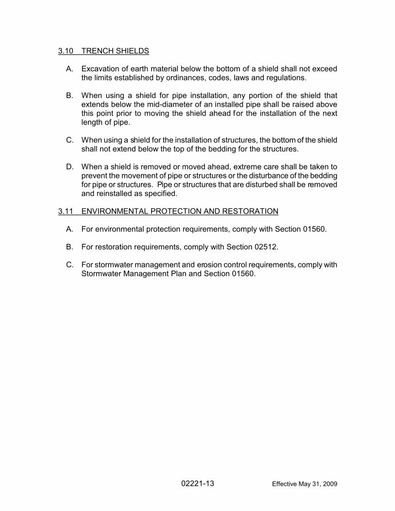
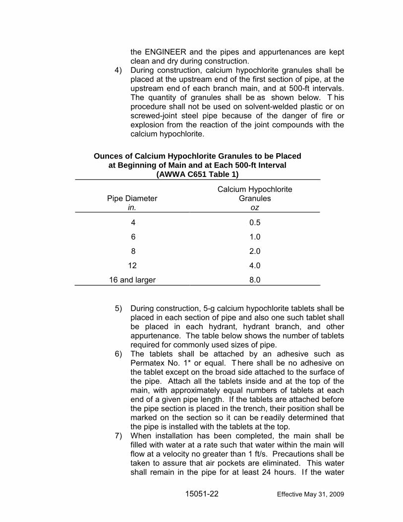
Effective May 31, 2009
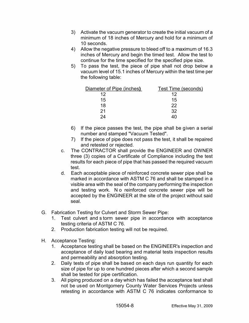
MONTGOMERY COUNTY ENVIRONMENTAL SERVICES MONTGOMERY COUNTY, OHIO BID SUBMITTAL DOCUMENT FOR PROJECT LOCATION PROJECT TITLE PROJECT NO. ********* CONTRACT NO. *** MONTH, YEAR JUDY DODGE ............................................................... COUNTY COMMISSIONER DAN FOLEY .................................................................. COUNTY COMMISSIONER DEBORAH A. LIEBERMAN .......................................... COUNTY COMMISSIONER JOSEPH P. TUSS ........................................................ COUNTY ADMINISTRATOR PATRICK TURNBULL, P.E. ............................. DIRECTOR/SANITARY ENGINEER DESIGN ENGINEER COMPANY NAME BID DATE: _____________________
TOC-1 Effective May 31, 2009
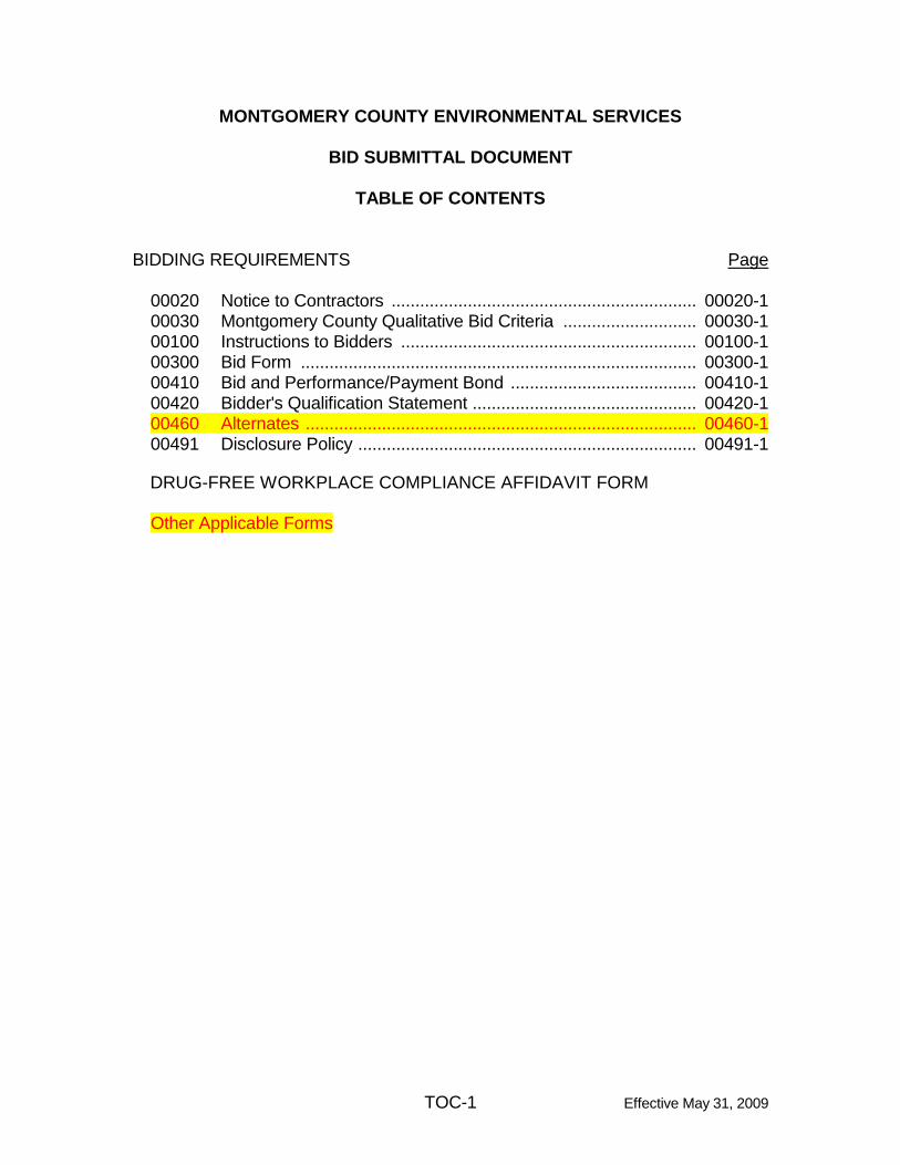
MONTGOMERY COUNTY ENVIRONMENTAL SERVICES
BID SUBMITTAL DOCUMENT
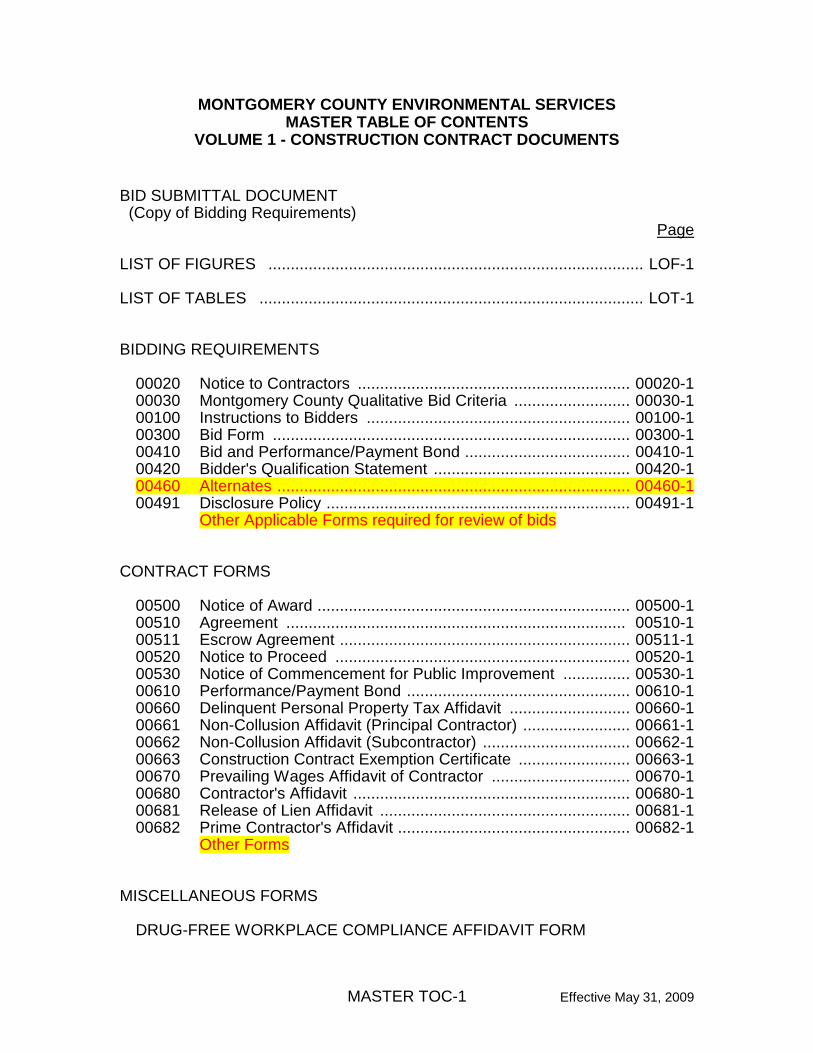
TABLE OF CONTENTS BIDDING REQUIREMENTS Page
00020 Notice to Contractors ................................................................ 00020-1 00030 Montgomery County Qualitative Bid Criteria ............................ 00030-1 00100 Instructions to Bidders .............................................................. 00100-1 00300 Bid Form ................................................................................... 00300-1 00410 Bid and Performance/Payment Bond ....................................... 00410-1 00420 Bidder's Qualification Statement ............................................... 00420-1 00460 Alternates .................................................................................. 00460-1 00491 Disclosure Policy ....................................................................... 00491-1 DRUG-FREE WORKPLACE COMPLIANCE AFFIDAVIT FORM
Other Applicable Forms
00020-1 Effective May 31, 2009
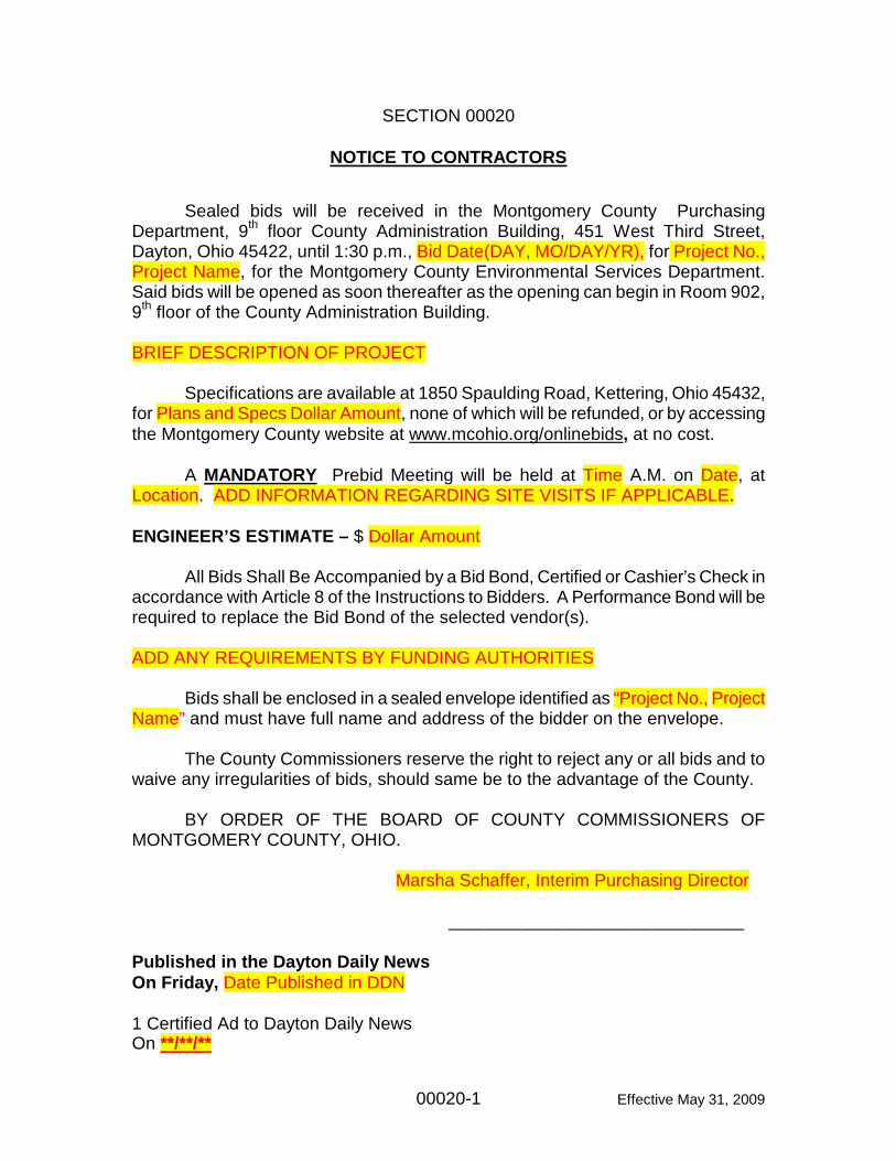
SECTION 00020
NOTICE TO CONTRACTORS Sealed bids will be received in the Montgomery County Purchasing Department, 9th floor County Administration Building, 451 West Third Street, Dayton, Ohio 45422, until 1:30 p.m., Bid Date(DAY, MO/DAY/YR), for Project No., Project Name, for the Montgomery County Environmental Services Department. Said bids will be opened as soon thereafter as the opening can begin in Room 902, 9th floor of the County Administration Building. BRIEF DESCRIPTION OF PROJECT Specifications are available at 1850 Spaulding Road, Kettering, Ohio 45432, for Plans and Specs Dollar Amount, none of which will be refunded, or by accessing the Montgomery County website at www.mcohio.org/onlinebids, at no cost. A MANDATORY Prebid Meeting will be held at Time A.M. on Date, at Location. ADD INFORMATION REGARDING SITE VISITS IF APPLICABLE. ENGINEER’S ESTIMATE – $ Dollar Amount All Bids Shall Be Accompanied by a Bid Bond, Certified or Cashier’s Check in accordance with Article 8 of the Instructions to Bidders. A Performance Bond will be required to replace the Bid Bond of the selected vendor(s). ADD ANY REQUIREMENTS BY FUNDING AUTHORITIES Bids shall be enclosed in a sealed envelope identified as “Project No., Project Name” and must have full name and address of the bidder on the envelope. The County Commissioners reserve the right to reject any or all bids and to waive any irregularities of bids, should same be to the advantage of the County. BY ORDER OF THE BOARD OF COUNTY COMMISSIONERS OF MONTGOMERY COUNTY, OHIO. Marsha Schaffer, Interim Purchasing Director ______________________________ Published in the Dayton Daily News On Friday, Date Published in DDN 1 Certified Ad to Dayton Daily News On **/**/**
00030-1 Effective May 31, 2009
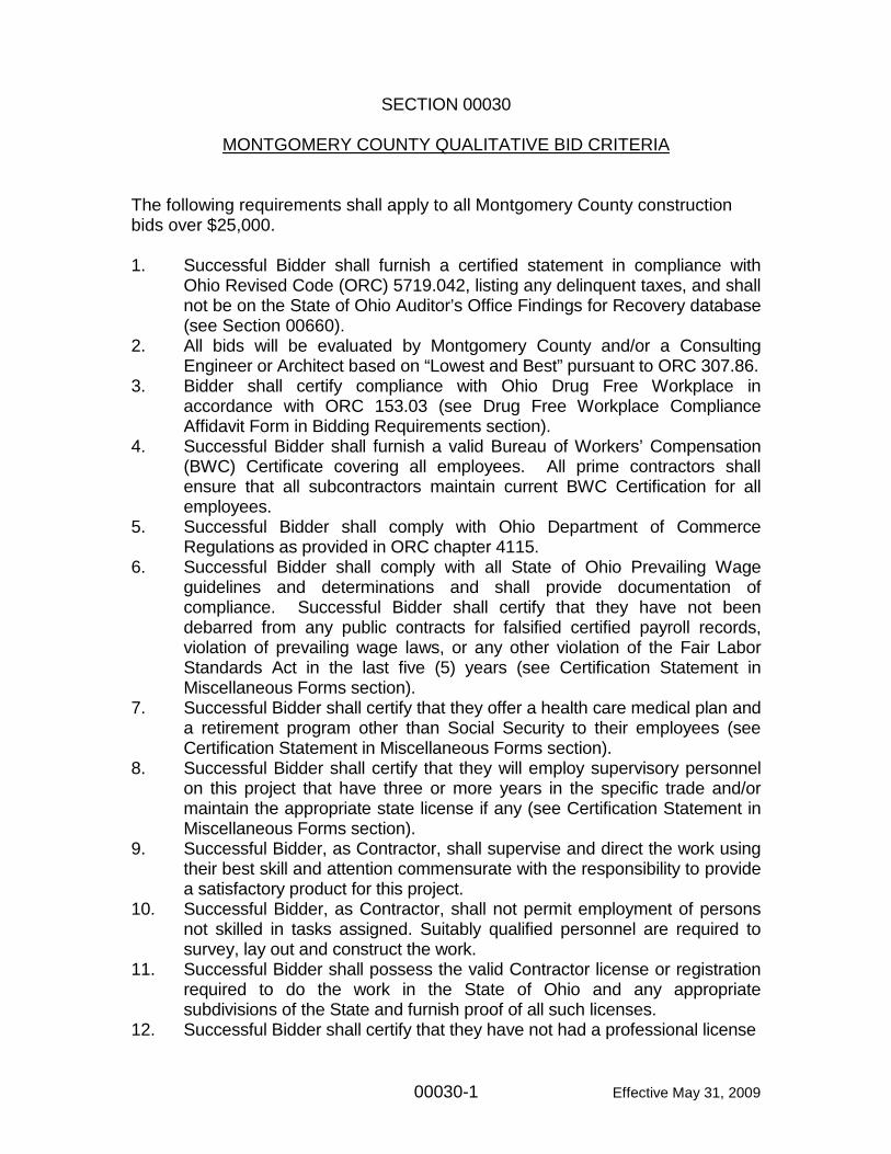
SECTION 00030
MONTGOMERY COUNTY QUALITATIVE BID CRITERIA
The following requirements shall apply to all Montgomery County construction bids over $25,000.
1. Successful Bidder shall furnish a certified statement in compliance with
Ohio Revised Code (ORC) 5719.042, listing any delinquent taxes, and shall not be on the State of Ohio Auditor’s Office Findings for Recovery database (see Section 00660).
2. All bids will be evaluated by Montgomery County and/or a Consulting Engineer or Architect based on “Lowest and Best” pursuant to ORC 307.86.
3. Bidder shall certify compliance with Ohio Drug Free Workplace in accordance with ORC 153.03 (see Drug Free Workplace Compliance Affidavit Form in Bidding Requirements section).
4. Successful Bidder shall furnish a valid Bureau of Workers’ Compensation (BWC) Certificate covering all employees. All prime contractors shall ensure that all subcontractors maintain current BWC Certification for all employees.
5. Successful Bidder shall comply with Ohio Department of Commerce Regulations as provided in ORC chapter 4115.
6. Successful Bidder shall comply with all State of Ohio Prevailing Wage guidelines and determinations and shall provide documentation of compliance. Successful Bidder shall certify that they have not been debarred from any public contracts for falsified certified payroll records, violation of prevailing wage laws, or any other violation of the Fair Labor Standards Act in the last five (5) years (see Certification Statement in Miscellaneous Forms section).
7. Successful Bidder shall certify that they offer a health care medical plan and a retirement program other than Social Security to their employees (see Certification Statement in Miscellaneous Forms section).
8. Successful Bidder shall certify that they will employ supervisory personnel on this project that have three or more years in the specific trade and/or maintain the appropriate state license if any (see Certification Statement in Miscellaneous Forms section).
9. Successful Bidder, as Contractor, shall supervise and direct the work using their best skill and attention commensurate with the responsibility to provide a satisfactory product for this project.
10. Successful Bidder, as Contractor, shall not permit employment of persons not skilled in tasks assigned. Suitably qualified personnel are required to survey, lay out and construct the work.
11. Successful Bidder shall possess the valid Contractor license or registration required to do the work in the State of Ohio and any appropriate subdivisions of the State and furnish proof of all such licenses.
12. Successful Bidder shall certify that they have not had a professional license
00030-2 Effective May 31, 2009
revoked in the past 5 years in Ohio or any other state (see Certification Statement in Miscellaneous Forms section).
13 Successful Bidder shall certify that they have implemented a Safety Program compliant with OSHA and all other laws and regulations and will provide evidence of such upon request. (see Certification Statement in Miscellaneous Forms section).
14. Contractor, within ten (10) days after award of the Contract, shall furnish in writing to Montgomery County the names of persons or entities (including those who are to furnish materials or equipment fabricated to a special design) proposed for each principal portion of the Work. The Board will promptly reply to the Contractor in writing after due investigation stating the Board has, or does not have any objection to any such proposed person or entity.
15. The following shall be conditions of bidding: a. Montgomery County may reject any or all Bids, may waive any and all
informalities not involving price, time or changes in the Work and may reject all nonconforming, nonresponsive or conditional Bids.
b. Montgomery County may reject any Bid not accompanied by specified documentation and Bid security.
c. Montgomery County may reject any Bid if it shows any omissions, alterations of form, additions not required or requested, conditions or qualifications, or irregularities of any kind.
d. Montgomery County may reject any Bid that, in it’s sole discretion, is considered to be unbalanced or unreasonable as to the amount bid for any lump sum or unit price item.
e. In evaluating Bids, Montgomery County will consider the qualifications of Bidders; whether or not the Bids comply with the prescribed require-ments; the alternatives, if any; the times or times for completion as stated in the Bid Form and the lump sum and unit prices, if requested in the Bid Form.
f. Montgomery County may consider the qualifications and experience of Subcontractors, Suppliers and other persons and organizations (including those who are to furnish the principal items of material or equipment) proposed for those portions of the Work as to which the identity of Subcontractors, Suppliers and other persons and organizations must be submitted as provided in the Supplementary Conditions.
g. Montgomery County may conduct such investigation as Montgomery County deems necessary to assist in the evaluation of any Bid and to establish the responsibility, qualifications and financial ability of the Bidders, proposed Subcontractors, Suppliers and other persons and organizations to perform and furnish the Work in accordance with the Contract Documents. Montgomery County reserves the right to reject the Bid of any Bidder who does not pass any such evaluation to Montgomery County’s satisfaction.
+ + END OF SECTION + +
00100-1 Effective May 31, 2009
SECTION 00100 INSTRUCTIONS TO BIDDERS (ALL CONTRACTS) TABLE OF ARTICLES
1. Defined Terms 2. Bids Received 3. Location and Description of Project 4. Copies of Bidding Documents 5. Qualifications of Bidders 6. Examination of Contract Documents and Site 7. Interpretations and Addenda 8. Bid Security 9. Contract Time 10. Liquidated Damages 11. Substitute Materials and Equipment 12. Subcontractors and Others 13. Basis for Bids 14. Preparation of Bid 15. Submission of Bid 16. Modification or Withdrawal of Bid 17. Opening of Bids 18. Disqualification of Bidders 19. Bids to Remain Open 20. Award of Contract 21. Contract Securities 22. Contractor's Insurance 23. Execution of Agreement 24. Notice to Proceed 25. Special Requirements 26. Engineer's Estimate
00100-2 Effective May 31, 2009
ARTICLE 1 - DEFINED TERMS 1.1 Terms used in these Instructions to Bidders, which are defined in the
General Conditions and Supplementary Conditions, have the meanings assigned to them in the General Conditions and Supplementary Conditions. The term "Successful Bidder" means the Bidder to whom OWNER (on the basis of OWNER's evaluation as hereinafter provided) makes an award.
1.2 Certain additional terms used in these Instructions to Bidders have the
meanings indicated below which are applicable to both the singular and plural thereof.
1.2.1 Bidder: One who submits a Bid directly to OWNER as distinct
from a sub-bidder, who submits a Bid to a Bidder.
1.2.2 Issuing Office: The office from which the Bidding Documents are to be issued and where the Bidding procedures are to be adminis-tered.
1.2.3 Successful Bidder: The lowest, responsible and responsive
Bidder to whom OWNER (on the basis of OWNER's evaluation as hereinafter provided) makes an award.
1.2.4 Bid Submittal Document: Separately bound set of documents
which must be submitted in its entirety by the Bidder with its Bid and which includes the following:
· Notice to Contractors · Instructions to Bidders · Bid Forms (with Bidder's Affidavit if corporation) · Bid Security · Bidder's Qualification Statement · Disclosure Policy · Drug-Free Workplace Compliance Affidavit Form · Alternates · Other Applicable Forms
ARTICLE 2 - BIDS RECEIVED 2.1 Refer to Notice to Contractors for information on receipt of Bids. ARTICLE 3 - LOCATION AND DESCRIPTION OF PROJECT 3.1 Refer to Section S-01010 or S-01011 of the General Requirements for the
location and description of the Project.
00100-3 Effective May 31, 2009
ARTICLE 4 - COPIES OF BIDDING DOCUMENTS 4.1 Refer to Notice to Contractors for information on examination and procure-
ment of Bidding Documents. 4.2 Complete sets of Bidding Documents shall be used in preparing Bids;
neither OWNER nor ENGINEER assumes any responsibility for errors or misinterpretations resulting from the use of incomplete sets of Bidding Documents.
4.3 OWNER and ENGINEER in making copies of Bidding Documents available
on the above terms do so only for the purpose of obtaining Bids for the Work and do not confer a license or grant for any other use.
ARTICLE 5 - QUALIFICATIONS OF BIDDERS 5.1 Bidders shall be experienced in the kind of work to be performed, shall have
the necessary equipment therefor, and shall possess sufficient capital to properly execute the Work within the time allowed. Bids received from Bidders who have previously failed to complete work within the time required, or who have previously performed similar work in an unsatisfactory manner, may be rejected. A Bid may be rejected if Bidder cannot show that he has the necessary ability, plant and equipment to commence the Work at the time prescribed and thereafter to prosecute and complete the Work at the rate or within the time specified. A Bid may be rejected if Bidder is already obligated for the performance of other work which would delay the commencement, prosecution or completion of the Work.
5.2 As evidence of Bidder's qualifications to perform the Work, Bidder shall
complete and submit with his Bid the Bidder's Qualification Statement which is bound in the Bidding Documents and Bid Submittal Document. Low Bidders may be asked to furnish additional data to demonstrate their qualifications.
5.3 The Bid must contain evidence of Bidder's qualification to do business in
the State of Ohio or covenant to obtain such qualification prior to execution of Agreement.
5.4 Bids will be received only from ______________ contractors who are
registered by the State of Ohio. (Use where required for MBE/WBE contractors, asbestos abatement contractors, etc.)
00100-4 Effective May 31, 2009
ARTICLE 6 - EXAMINATION OF CONTRACT DOCUMENTS AND SITE 6.1 It is the responsibility of each Bidder before submitting a Bid.
6.1.1 To examine thoroughly the Contract Documents and other related data identified in the Bidding Documents (including "technical data" referred to below);
6.1.2 To visit the site to become familiar with and satisfy Bidder as to the
general, local and site conditions that may affect cost, progress, performance or furnishing of the Work;
6.1.3 To consider federal, state and local laws, ordinances, rules and
regulations that may affect cost, progress, performance or furnishing of the Work;
6.1.4 To examine the Contract Documents for other work to be
performed on the Project that relates to the Work for which the Bid is to be submitted
6.1.5 To study and carefully correlate Bidder's knowledge and
observations with the Contract Documents such other related data; and
6.1.6 To promptly notify ENGINEER in writing or at the mandatory Pre-
Bid Meeting of all conflicts, errors, ambiguities or discrepancies which Bidder has discovered in or between the Contract Documents and such other related documents.
DELETE EITHER "6.2" OR "6.3" TEXT, WHICHEVER IS NOT APPLICABLE. FOR SECTION THAT DOES NOT APPLY, REPLACE TEXT WITH “Not used.” TO MAINTAIN NUMBERING. Review the distribution of soil reports with the Project Manager. Decide if the reports are to be bound with the sets, sold separately on request only, etc. 6.2 Reference is made to the Supplementary Conditions for the identification of
those reports of investigations and tests of subsurface and latent physical conditions at the site or those reports that otherwise may affect cost, progress, performance or furnishing of the Work which have been utilized by ENGINEER in preparation of the Drawings and Specifications. Copies of such reports are included as a separately bound document and are furnished with each set of the Bidding Documents (modify if necessary). These reports are not intended to constitute any explicit or implicit representation as to the nature of the subsurface and latent physical conditions which may be encountered at the site or to constitute explicit or
00100-5 Effective May 31, 2009
implicit representations as to any other matter contained in any report. Such reports are not guaranteed as to completeness and are not part of the Contract Documents. Before submitting Bid, Bidder will, at its own expense, make such investigations and tests as the Bidder may deem necessary to determine its Bid for performing and furnishing the Work in accordance with the Contract Documents.
6.3 Neither the OWNER nor the ENGINEER has performed any subsurface
investigation in connection with the design of this Project nor have they utilized any investigation which may have been performed by others. Before submitting its Bid, Bidder will at its own expense, make such investigations and tests as the Bidder may deem necessary to determine its Bid for performing and furnishing the Work in accordance with the Contract Documents.
6.4 On request and by appointment, OWNER will conduct a site visit during
OWNER's normal business hours for any Bidder requesting such a visit. All visits shall be scheduled through an OWNER's representative at 1850 Spaulding Road, Dayton, Ohio 45432, phone no.: 937-781-2500.
6.5 On request, OWNER will provide each Bidder access to the site to conduct
such investigations and tests as each Bidder deems necessary for submission of its Bid. Bidder must fill all holes and clean up and restore the site to its former conditions upon completion of such explorations, investigations, tests and studies.
IF CERTAIN LANDS OR RIGHTS-OF-WAY WILL NOT BE AVAILABLE WHEN NOTICE TO PROCEED IS GIVEN, NOTE BELOW AND PROVIDE CROSS REFERENCE TO DOCUMENT WHERE SAID LANDS ARE DESCRIBED. 6.6 The lands upon which the Work is to be performed, rights-of-way for access
thereto and other lands designated for use by CONTRACTOR in performing the Work are identified in the Supplementary Conditions, General Requirements or Drawings.
6.7 Reference is made to the Supplementary Conditions for the identification of
the general nature of work that is to be performed at the site by OWNER or others (such as utilities and other prime Contractors) that relates to the Work for which a Bid is to be submitted. On request, OWNER will provide to each Bidder for examination access to or copies of Contract Documents (other than portions thereof related to price) for such work.
6.8 The submission of a Bid will constitute an incontrovertible representation by
Bidder that it has complied with every requirement of this Article 6, that without exception the Bid is premised upon performing and furnishing the Work required by the Contract Documents and applying the specific means, methods, techniques, sequences or procedures of construction (if any) that
00100-6 Effective May 31, 2009
may be shown or indicated or expressly required by the Contract Documents, that Bidder has given ENGINEER written notice of all conflicts, errors, ambiguities and discrepancies that Bidder has discovered in the Contract Documents and the written resolutions thereof by ENGINEER is acceptable to Bidder, and that the Contract Documents are generally sufficient in scope and detail to indicate and convey understanding of all terms and conditions for performing and furnishing the Work.
6.9 The provisions of Paragraphs 6.2 through 6.8, inclusive of the Instructions
to Bidders, do not apply to Asbestos, Polychlorinated biphenyls (PCBs), Petroleum, Hazardous Waste or Radioactive Material covered by Paragraphs 4.11 through 4.15 of the General Conditions.
ARTICLE 7 - INTERPRETATIONS AND ADDENDA 7.1 All questions about the meaning or intent of the Bidding Documents or the
Contract Documents shall be submitted to ENGINEER in writing. In order to receive consideration, questions must be received by ENGINEER at least eight (8) days prior to the date fixed for the opening of Bids. Any interpretations of questions so raised, which in the opinion of ENGINEER require interpretations, will be issued by Addenda mailed or delivered to all parties recorded by ENGINEER as having received the Bidding and Contract Documents for receipt not later than three (3) days prior to the date fixed for the opening of Bids. Only questions answered by formal written Addenda will be binding. Oral and other interpretations or clarifications will be without legal effect.
7.2 OWNER may issue such additional Addenda as may be necessary to
clarify, correct or change the Bidding Documents or the Contract Documents. Such Addenda, if any, will be issued in the manner and within the time period stated in Paragraph 7.1 of the Instructions to Bidders.
ARTICLE 8 - BID SECURITY 8.1 Each Bid must be accompanied by either a Bid Bond for the full amount of
the Bid issued by a bonding company authorized to do business in the State of Ohio; or by a certified check, cashier's check, or letter of credit pursuant to Chapter 1305 of the Ohio Revised Code from a solvent bank in Montgomery County, Ohio, in the sum of 10 percent of the amount of the Bid, satisfactory to the OWNER. The required Bid Bond(s) shall be made payable to the Board of County Commissioners, the County of Montgomery, State of Ohio, and certified checks, cashier's checks, or letters of credit shall be made payable to the Board of County Commissioners of Montgomery County.
00100-7 Effective May 31, 2009
8.2 Bid Bond shall be on the form bound in the Bidding Documents and Bid Submittal Document or on another form which satisfies the requirements of Section 153.54 and 153.571 of the Ohio Revised Code. Bid Bond shall be issued by a surety meeting the requirements of Paragraph 5.1 of the General Conditions.
8.3 The Bid security of the Successful Bidder will be retained until such Bidder
has executed the Agreement, furnished the required contract security, and met the other conditions of the Notice of Award whereupon the Bid security will be returned. If the Successful Bidder fails to execute and deliver the Agreement and furnish the required contract security within ten (10) days of the Notice of Award, OWNER may annul the Notice of Award and may retain from the Bid security an amount equal to the damages which OWNER may suffer by reason of such failure. Such amount not to exceed the Bid security amount.
8.4 The Bid security of other Bidders whom OWNER believes to have a
reasonable chance of receiving the award may be retained by OWNER until the seventh (7th) day after the Effective Date of the Agreement by the Successful Bidder, where upon Bid security furnished by such Bidders will be returned. Bid security with Bids which are not competitive of other Bidders will be returned within seven (7) days after the Bid opening.
8.5 The successful Bidder shall be required to file performance/payment bond
in the full amount of the Contract pursuant to Section 153.54 (C) of the Ohio Revised Code and Paragraphs 5.1 and 5.2 of the General Conditions.
8.6 All Bid guarantees above must comply with applicable sub-sections of
Section 153.54 of the Ohio Revised Code. ARTICLE 9 - CONTRACT TIMES 9.1 The number of days within which the Work is to be substantially completed,
the Contract Completion Date and the Contract Expiration Date (the Contract Time) are defined by the Milestones set forth in the Agreement.
9.2 If the Contract Substantial Completion Date, Contract Completion Date and
the Contract Expiration Date are not defined in the Agreement, Bidder shall provide time periods as allowed on the Bid Form.
ARTICLE 10 - LIQUIDATED DAMAGES 10.1 Provisions for liquidated damages, if any, are set forth in the Agreement.
00100-8 Effective May 31, 2009
ARTICLE 11 - SUBSTITUTE MATERIAL AND EQUIPMENT 11.1 Whenever it is indicated in the Drawings or specified in the Specifications
that a substitute or "or-equal" item of material or equipment may be furnished or used by CONTRACTOR if acceptable to ENGINEER, application for such acceptance will not be considered by ENGINEER until after the Effective Date of the Agreement unless otherwise stated in Section 00460 Alternates (if included in the Bidding Documents). The procedure for submittal of any such application by CONTRACTOR and consideration by ENGINEER is set forth in Paragraph 6.7 of the General Conditions which may be supplemented in the General Requirements and Section 00460 Alternates.
11.2 As more fully discussed in Section 00460, "or equal" or substitute
proposals for items listed by ENGINEER in Section 00460 must be included with Bid Document Submittal and will not be considered after the Bids are opened. If Bidder desires ENGINEER to consider "or equal" or substitute proposals for items listed by ENGINEER in Section 00460, Bidder shall comply with the requirements of Section 00460.
11.3 For items not listed in Section 00460 Alternates, refer to Section S-01630 of
the General Requirements (if included in the Bidding Documents) for the period of time after the Effective Date of the Agreement during which the ENGINEER will accept applications for substitute or "or-equal" items of material or equipment.
ARTICLE 12 - SUBCONTRACTORS AND OTHERS 12.1 If the Supplementary Conditions require the identity of certain
Subcontractors and other persons and organizations (including those who are to furnish the principal items of material and equipment) to be submitted to OWNER in advance of a specified date prior to the Effective Date of the Agreement, apparent Successful Bidder, and any other Bidder so requested, will within five (5) days after Bid opening submit to OWNER a list of all such Subcontractors, Suppliers and other persons and organizations proposed for those portions of the Work for which such identification is required. Such list shall be accompanied by an experience statement with pertinent information regarding similar projects and other evidence of qualification for each such Subcontractor, Supplier, person or organization if requested by OWNER. The OWNER or ENGINEER who after due investigation has reasonable objection to any proposed Subcontractor, Supplier, other person or organization, may before giving the Notice of Award request the apparent Successful Bidder to submit an acceptable substitute without an increase in Bid price. If apparent Successful Bidder declines to make any such substitution, OWNER may award contract to the next lowest Bidder that proposes to use acceptable Subcontractors,
00100-9 Effective May 31, 2009
Suppliers and other persons and organizations. The declining to make requested substitutions will not constitute grounds for sacrificing the Bid security of any Bidder. Any Subcontractor, Supplier, other person or organization listed and to whom OWNER or ENGINEER does not make written objection prior to the giving of the Notice of Award will be deemed acceptable to OWNER and ENGINEER subject to revocation of such acceptance after the Effective Date of the Agreement as provided in Paragraphs 6.10 and 6.11 of the General Conditions.
12.2 If the CONTRACTOR requests approval of a Subcontractor, Supplier or
other persons or organizations after the Effective Date of the Agreement, the request shall be accompanied by an experience statement with pertinent information regarding similar projects ad other evidence of qualification for each such Subcontractor, Supplier, person or organization. An OWNER or ENGINEER, who after due investigation has reasonable objection to any proposed Subcontractor, Supplier, other person or organization, may require the CONTRACTOR to submit an acceptable substitute. The CONTRACTOR shall propose a suitable substitution for his proposed Subcontractor, Supplier or other persons or organizations without an increase in Contract Price.
12.3 No CONTRACTOR shall be required to employ any Subcontractor, other
person or organization against whom he has reasonable objection. ARTICLE 13 - BASIS FOR BIDS DELETE BELOW IF ALTERNATIVES NOT USED. 13.1 Bids must be priced on a unit price or lump sum basis for the base contract
and include a separate price for each alternate described in the Specifications as provided for in the Bid Form. Bids will be evaluated and Contract awarded using base bid prices only.
DELETE BELOW IF ALLOWANCES NOT USED. 13.2 The Bid price shall include such amounts as the Bidder deems proper for
overhead and profit on account of cash allowances named in the Contract Documents as provided in paragraph 11.8 of the General Conditions.
(Include statement indicating how bids will be evaluated if 13.1 or 13.2 do not apply).
ARTICLE 14 - PREPARATION OF BID 14.1 A Bid must be made on the separately bound Bid Submittal Document
00100-10 Effective May 31, 2009
purchased from the OWNER with the Bidding Documents. The Bid Submittal Document shall not be altered in any way.
14.2 The Bid Form and other forms, policies, and statements must be completed
by printing in ink or by typewriter. Blank spaces in the Bid Form must be filled in correctly where indicated, and the Bidder must state, both in words and numerals, the prices proposed for each and every item of Work. Ditto marks shall not be used.
14.3 Alterations to completed information on the forms must be initialed by the
individual who has signed the Bid Forms. 14.4 One original plus two copies of the complete executed Bid Submittal
Document must be submitted by the Bidder with its Bid. 14.5 Bid shall be executed as stated below.
A. Bids by an individual shall show the Bidder's name and official address.
B. Bids by partnerships must be executed in the partnership name and signed by a partner, whose title must appear under the signature and the official address of the partnership shall be shown below the signature.
C. Bids by corporations must be executed in the corporate name by an officer
of the corporation and must be accompanied by the affidavit provided with Bid Form or a certified copy of a resolution of the board of directors authorizing the person signing the Bid to do so on behalf of the corporation. The corporate seal shall be affixed and attested by the secretary or an assistant secretary. The state of incorporation and the official corporate address shall be shown below the signature.
D. Bids by joint ventures must be executed in the joint venture name by an
officer of each joint venture party. The requirements for each party (individual, partnership or corporation) of the joint venture shall be as defined in paragraphs 14.5 A., 14.5 B. and 14.5 C. above.
E. All names must be typed or printed in ink below the signature.
F. Contractor's license or registration number shall be entered in the space
provided on the Bid Form. Evidence of authority to conduct business as an out-of-state corporation in the State of Ohio shall be provided in accordance with Article 5 above.
G. The address and telephone number for communications regarding the Bid
shall be shown. 14.6 The Bid shall contain an acknowledgement of the receipt of all Addenda in
00100-11 Effective May 31, 2009
the space provided on the Bid Form. The addenda numbers must be filled in on the Bid Form.
14.7 In addition to the Bid Form, the following listed documents, which will be
purchased from the OWNER and is contained in the Bid Submittal Document, shall be executed in the manner described in Paragraph 14.5 unless another manner is indicated.
A. Bid Security. B. Bidder's Qualification Statement. C. Disclosure Policy. D. If Bidder is a corporation, Bidder's Affidavit included with the Bid Form or
signatory authorization resolution of corporation. E. Drug-Free Workplace Compliance Affidavit Form.
F. Base Bid Equipment/Materials List.
G. Alternate Bid Equipment/Materials List. H. Other Applicable Forms.
ARTICLE 15 - SUBMISSION OF BIDS 15.1 Bids shall be submitted at the time and place indicated in the Notice to
Contractors. 15.2 Bid shall be enclosed in an opaque sealed envelope plainly marked on the
outside with the name and address of the Bidder, its license or registration number if applicable, the name of the Project, the contract name or number and the name of the person who signed the Bid Form. Bid shall be submitted with Bid security and other required documents. One original plus two copies of the complete executed Bid Submittal Document must be submitted by the Bidder with its Bid.
15.3 If the Bid is sent through the mail or other delivery system, the sealed
envelope containing the Bid shall be enclosed in another envelope plainly marked on the outside with the notation "Bid Enclosed". Mailed Bids shall be addressed to: Board of County Commissioners, Montgomery County, Administration Building, 451 West 3rd Street, Dayton, Ohio 45422. Attention: Purchasing Director. The name of the person who signed the Bid Form shall be written on the outside envelope.
00100-12 Effective May 31, 2009
15.4 If Bids are forwarded by U.S. Postal Service, delivery shall be by registered or certified mail.
ARTICLE 16 - MODIFICATION OR WITHDRAWAL OF BID 16.1 Withdrawal Prior to Bid Opening:
A. A Bidder may withdraw its Bid before the time fixed for the opening of Bids by communicating his purpose in writing to the OWNER. Upon receipt of such written notice signed by the person who signed the Bid Form, the unopened Bid will be returned to the Bidder.
16.2 Modification Prior to Bid Opening:
A. If a Bidder wishes to modify its Bid, it must withdraw its initial Bid in the manner specified in Paragraph 16.1 A and submit a new Bid.
ARTICLE 17 - OPENING OF BIDS 17.1 Bids will be opened as indicated in the Notice to Contractors. 17.2 Bids received by mail or otherwise after the time specified for the opening of
Bids will not be accepted and will be returned to the Bidder unopened. ARTICLE 18 - DISQUALIFICATION OF BIDDERS 18.1 More than one (1) Bid for the same Work from an individual, or a firm,
partnership, corporation or an association under the same or different names will not be considered. Reasonable grounds for believing that any Bidder is interested in more than one (1) Bid for the Work may be cause for disqualification of that Bidder and the rejection of all Bids in which that Bidder is interested, unless the Bidding Documents specifically invite or permit combination Bids.
ARTICLE 19 - BIDS TO REMAIN SUBJECT TO ACCEPTANCE 19.1 All Bids shall remain subject to acceptance for sixty (60) days after the day
of the Bid opening, but OWNER may, in its sole discretion, release any Bid and return the Bid security prior to that date.
00100-13 Effective May 31, 2009
ARTICLE 20 - AWARD OF CONTRACT 20.1 OWNER reserves the right to reject any or all Bids, to waive any and all
informalities not involving price, time or changes in the Work and the right to reject all nonconforming, nonresponsive or conditional Bids.
20.2 OWNER reserves the right to reject any Bid not accompanied by specified
documentation and Bid security. 20.3 OWNER reserves the right to reject any Bid if it shows any omissions,
alterations of form, additions not called for, conditions or qualifications, or irregularities of any kind.
20.4 OWNER reserves the right to reject any Bid that, in his sole discretion, is
considered to be unbalanced or unreasonable as to the amount bid for any lump sum or unit price item.
20.5 In evaluating Bids, the following criteria will be used: Discrepancies
between the indicated sum of any row of figures and the correct sum thereof will be resolved in favor of the correct sum; discrepancies in the multiplication of estimated quantities and unit cost prices will be resolved in favor of the unit cost prices; discrepancies between the indicated sum of any column of figures and the correct sum thereof will be resolved in favor of the correct sum; for costs or prices described in both words and figures, discrepancies between words and figures will be resolved in favor of words.
20.6 In evaluating Bids, OWNER will consider the qualifications of Bidders;
whether or not the Bids comply with the prescribed requirements; the alternatives, if any; the times or times for completion as stated in the Bid Form and the lump sum and unit prices, if requested in the Bid Form.
20.7 OWNER may consider the qualifications and experience of Subcontractors,
Suppliers and other persons and organizations (including those who are to furnish the principal items of material or equipment) proposed for those portions of the Work as to which the identity of Subcontractors, Suppliers and other persons and organizations must be submitted as provided in the Supplementary Conditions.
20.8 OWNER may conduct such investigation as OWNER deems necessary to
assist in the evaluation of any Bid and to establish the responsibility, qualifications and financial ability of the Bidders, proposed Subcontractors, Suppliers and other persons and organizations to perform and furnish the Work in accordance with the Contract Documents. OWNER reserves the right to reject the Bid of any Bidder who does not pass any such evaluation to OWNER's satisfaction.
20.9 If a contract is to be awarded, it will be awarded to the lowest responsive
00100-14 Effective May 31, 2009
and responsible Bidder who has neither been disqualified nor rejected pursuant to Article 18 or this Article 20.
20.10 The estimate of quantities of work, if included in the Bid Form, is
approximate only, and will not become the basis for calculating the final payment for the Work. However, the estimated quantities shall be used by the OWNER in calculating the total amount of the Bid for comparison with other Bids.
For projects to be bid by multiple primes, add the following paragraph and prepare the Bid Form as required. 20.11 It is intended that separate contracts will be awarded to the lowest
responsive Bidders on each Contract or to the Bidder who submits a combined Bid on two or more contracts which is lower than the total of separate Bids on such contracts.
ARTICLE 21 - CONTRACT SECURITIES 21.1 The amount of and other requirements for the Performance/Payment Bond
are stated in Paragraph 5.1 of the General Conditions. The requirements for delivery of Bonds are stated in Paragraph 2.1 of the General Conditions. Additional requirements may be stated in the Supplementary Conditions.
21.2 The Successful Bidder shall within ten (10) days from the date of the Notice
of Award deliver to OWNER, for his review and approval, the Performance Bond/Payment Bond he proposes to furnish at the time of the execution of the Agreement. The bond shall be made on the form included in the Bidding Documents or on another form which satisfies the requirements of Section 153.54 and 153.57 of the Ohio Revised Code. If the bid security was furnished in the form of a Bid and Performance/Payment Bond, an additional Performance/Payment Bond will not be required provided it meets all the requirements of the Performance/Payment Bond.
ARTICLE 22 - CONTRACTOR'S INSURANCE 22.1 The requirements for CONTRACTOR'S insurance are stated in Article 5 of
the General Conditions and in the Supplementary Conditions. The requirements for delivery of certificates of insurance are stated in Paragraph 2.1 of the General Conditions.
22.2 The Successful Bidder shall within ten (10) days from the date of the Notice
of Award deliver to OWNER, workers' compensation certificates and certificates of insurance as required to comply with the Contract Documents.
00100-15 Effective May 31, 2009
ARTICLE 23 - EXECUTION OF AGREEMENT 23.1 The Successful Bidder, or its authorized representative, will be required to
execute the Agreement within thirty (30) days from the date of receipt of the Agreement, prior to execution of the Agreement by OWNER.
ARTICLE 24 - NOTICE TO PROCEED 24.1 Issuance of the Notice to Proceed shall be as stated in Article 2 of the
General Conditions. ARTICLE 25 - SPECIAL REQUIREMENTS 25.1 Particular attention is called to the statutory requirements of the State of
Ohio relative to licensing of corporations organized under the laws of any other state. These requirements include, but are not necessarily limited to, the stipulations contained in Section 1703.04 of the Ohio Revised Code.
25.2 The Successful Bidder shall execute the Delinquent Personal Property Tax
Affidavit, which is bound into the Bidding Documents and Bid Submittal Document, in accordance with Section 5719.042 of the Ohio Revised Code. The Affidavit shall be submitted to the Montgomery County Treasurer and a copy shall be incorporated into the Contract.
25.3 The Bidder shall disclose, in writing, on the Disclosure Policy form included
in the Bidding Documents and Bid Submittal Document, the knowledge of any business relationship or interest that any Montgomery County employee, an employee's immediate family, or any other contractor or subcontractor of said Bidder may have with Bidder. This policy is in accordance with Resolution No. 88-1276 adopted by the Board of County Commissioners, Montgomery County, Ohio on July 6, 1988.
25.4 The Bidder shall certify, by notarized statement, on the Drug-Free
Workplace Compliance Affidavit Form, that it is enrolled and in good standing with the Ohio Bureau of Workers’ Compensation Drug-Free Workplace Program, or enrolled and in good standing with a comparable program, which has been approved by the Bureau of Workers’ Compensation, prior to providing any labor at the project site of the public improvement, which is the subject of this bid, pursuant to O.R.C. § 153.03 and § 153.031.
The Bidder shall also agree, on the same affidavit, that it will be
contractually responsible for ensuring that all subcontractors of any tier shall be enrolled and in good standing with the Ohio Bureau of Workers’ Compensation, or with a comparable Bureau approved program, prior to the
00100-16 Effective May 31, 2009
provision of any labor at the subject public project site by any such subcontractor.
25.5 A mandatory Pre-Bid Meeting will be held at the time and place stated in the
Notice to Contractors. The Pre-Bid attendance will determine who will be allowed to submit proposals. Bids from Contractors not in attendance at the Pre-Bid Meeting will be rejected as non-responsive. The purpose of the Pre-Bid Meeting will be to answer questions related to the Bidding Documents from interested Bidders. It is paramount that Bidders recognize that the purpose of the Pre-Bid Meeting is to resolve ambiguities, inconsis-tencies, errors, or omissions in the Bidding Documents.
25.6 OWNER is organized and exists as a political subdivision under the laws of
the State of Ohio and maintains an exempt status relative to sales tax for equipment and materials incorporated into this Work. The price or prices bid, whether unit price or lump sum, shall be exclusive of such taxes and will be so construed. An Exemption Certificate, which is bound into the Bidding Documents, will be executed and provided to the Successful Bidder following execution of the Agreement.
25.7 All construction activity in or near a stream shall be performed in
accordance with the terms of Nationwide Permit 33 CFR 331 (12) and Statewide permit 401. The conditions and requirements of these permits are included in these contract documents for use by the Contractor. Tree planting requirements shall be bid as part of the restoration costs for each parcel.
25.8 The Successful Bidder will be required to obtain permit coverage from the
Ohio Environmental Protection Agency under permit OHC000002. Coverage will require the Successful Bidder to submit a Notice of Intent (NOI), a site map (8 1/2 ” x 11”), a permit fee (expected fee between $200 and $500) and prepare a Storm Water Pollution Prevention Plan. See Miscellaneous Forms for the NOI form and instructions.
25.9 Refer to Supplementary Conditions for further requirements.
00100-17 Effective May 31, 2009
ARTICLE 26 - ENGINEER'S ESTIMATE
Contract No. G - General $____________ Contract No. H - Heating, Ventilating and
Air Conditioning $____________ Contract No. P - Plumbing $____________ Contract No. E - Electrical $____________
DESIGN ENGINEER: Name Address Address Phone: ***-***-****
+ + END OF SECTION + +
00300-1 Effective August 1, 2007
SECTION 00300
BID FORM BID FOR:
MONTGOMERY COUNTY, OHIO
PROJECT NAME CONTRACT NO. ***
PROJECT NO. *********
BID TO:
BOARD OF COUNTY COMMISSIONERS MONTGOMERY COUNTY, OHIO
MONTGOMERY COUNTY ADMINISTRATION BUILDING 451 WEST THIRD STREET
(Print or Type Name of Bidder) (A Corporation/A Partnership/An Individual/A Joint Venture)
[Bidder to strike out inapplicable terms.] Commissioners:
1. The undersigned Bidder offers and agrees, if this Bid is accepted, to enter into an Agreement with OWNER in the form included in the Contract Documents to perform and furnish all Work as specified or indicated in the Contract Documents for the Bid Price and within the Bid Times indicated in this Bid and in accordance with other terms and conditions of the Contract Documents.
2. Bidder accepts all of the terms and conditions of the Notice to
Contractors and Instructions to Bidders, including without limitation those dealing with the disposition of Bid security. This Bid will remain subject to acceptance for sixty (60) days after the day of Bid opening. Bidder will sign and deliver the required number of counterparts of the Agreement with the Bonds and other documents required by the Bidding Requirements within ten (10) days after the date of OWNER's Notice of Award.
3. In submitting this Bid, Bidder represents, as more fully set forth in the
Agreement, that:
00300-2 Effective August 1, 2007
a. Bidder has examined and carefully studied the Bidding Documents and the following Addenda receipt of all which is hereby acknowl-edged:
Addendum No. Date Received __________________ __________________ __________________
b. Bidder has visited the site and become familiar with and is satisfied
as to the general, local and site conditions that may affect cost, progress, performance and furnishing of the Work.
c. Bidder is familiar with and is satisfied as to all federal, state and
local Laws and Regulations that may affect cost, progress, performance and furnishing of the Work.
d. Bidder has carefully studied all reports of explorations and tests of
subsurface conditions at or contiguous to the site and all drawings of physical conditions in or relating to existing surface or subsurface structures at or contiguous to the site (except underground Facilities) which have been identified in the Supplementary Conditions as provided in paragraph 4.2 of the General Conditions. Bidder acknowledges that such reports and drawings are not Contract Documents and may not be complete for Bidder's purposes. Bidder acknowledges that OWNER and ENGINEER do not assume responsibility for the accuracy or completeness of information and data shown or indicated in the Bidding Documents with respect to Underground Facilities at or contiguous to the site. Bidder has obtained and carefully studied (or assumes responsibility for having done so) all such additional or supplementary examinations, investigations, explorations, tests, studies and data concerning conditions (surface, subsurface and Underground Facilities) at or contiguous to the site or otherwise which may affect cost, progress, performance or furnishing of the Work or which relate to any aspect of the means, methods, techniques, sequences and procedures of construction to be em-ployed by Bidder and safety precautions and programs incident thereto and has included all such in the bid. Bidder does not con-sider that any additional examinations, investigations, explorations, tests, studies or data are necessary for the determination of this Bid for performance and furnishing of the Work in accordance with the times, price and other terms and conditions of the Contract Docu-ments.
00300-3 Effective August 1, 2007
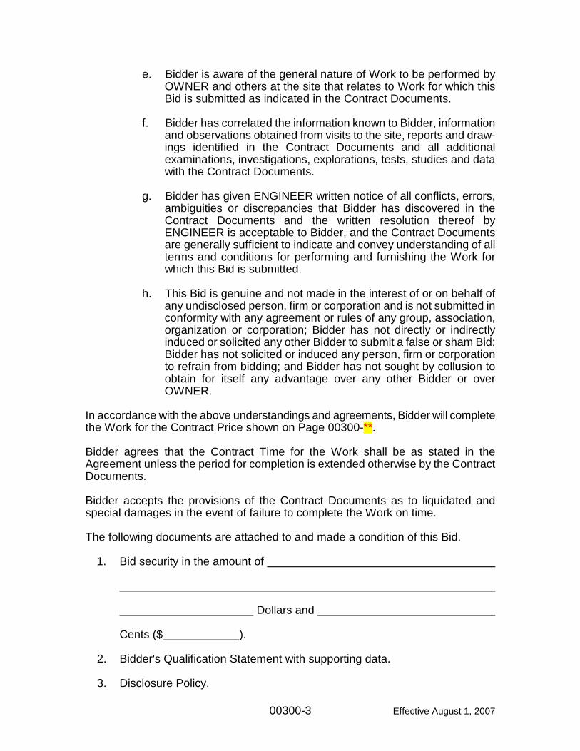
e. Bidder is aware of the general nature of Work to be performed by OWNER and others at the site that relates to Work for which this Bid is submitted as indicated in the Contract Documents.
f. Bidder has correlated the information known to Bidder, information
and observations obtained from visits to the site, reports and draw-ings identified in the Contract Documents and all additional examinations, investigations, explorations, tests, studies and data with the Contract Documents.
g. Bidder has given ENGINEER written notice of all conflicts, errors,
ambiguities or discrepancies that Bidder has discovered in the Contract Documents and the written resolution thereof by ENGINEER is acceptable to Bidder, and the Contract Documents are generally sufficient to indicate and convey understanding of all terms and conditions for performing and furnishing the Work for which this Bid is submitted.
h. This Bid is genuine and not made in the interest of or on behalf of
any undisclosed person, firm or corporation and is not submitted in conformity with any agreement or rules of any group, association, organization or corporation; Bidder has not directly or indirectly induced or solicited any other Bidder to submit a false or sham Bid; Bidder has not solicited or induced any person, firm or corporation to refrain from bidding; and Bidder has not sought by collusion to obtain for itself any advantage over any other Bidder or over OWNER.
In accordance with the above understandings and agreements, Bidder will complete the Work for the Contract Price shown on Page 00300-**. Bidder agrees that the Contract Time for the Work shall be as stated in the Agreement unless the period for completion is extended otherwise by the Contract Documents. Bidder accepts the provisions of the Contract Documents as to liquidated and special damages in the event of failure to complete the Work on time. The following documents are attached to and made a condition of this Bid.
1. Bid security in the amount of Dollars and Cents ($ ).
2. Bidder's Qualification Statement with supporting data.
The terms used in this Bid, which are defined in the General and Supplementary Conditions, have the meanings assigned to them in the General and Supplementary Conditions.
00300-5 Effective August 1, 2007
Respectfully submitted on , 20 . If BIDDER is: An Individual By
(Individual's Signature)
(Printed or Typed Name of Individual) Doing business as License or Registration Number: Business Address: Phone No.: A Partnership By
(Firm Name)
(Partner's Signature)
(Printed or Typed Name and Title of Partner) License or Registration Number: Business Address: Phone No.:
00300-6 Effective August 1, 2007
A Corporation (Bidder shall complete attached Affidavit) By (Corporation Name) By (Signature of Officer Authorized to Sign) (Printed or Typed Name and Title of Officer Authorized to Sign) (State of Incorporation) (CORPORATE SEAL) Attest (Secretary) License or Registration Number: Business Address: Phone No.:
00300-7 Effective August 1, 2007
A Joint Venture (If Bidder is a corporation, complete the attached Affidavit) By (Joint Venture Name) (Signature of Authorized Representative) (Printed or Typed Name of Authorized Representative) (Signature of Authorized Representative) (Printed or Typed Name of Authorized Representative) License or Registration Number: Business Address: Phone No.: CORPORATE SEAL(S) Attest (Secretary) License or Registration Number: Business Address: Phone No.: Each party of the joint venture must sign. The manner of signing for each individual, partnership and corporation that is a party to the joint venture shall be as indicated above.
00300-8 Effective August 1, 2007
BIDDER'S AFFIDAVIT (To be filled in and executed if Bidder is a Corporation) COUNTY OF )
)ss: STATE OF ) , being duly sworn, deposes and says that he is Secretary of a Corporation organized and existing under and by virtue of the laws of the State of , and having its principal office at (Street and Number) (City) (County) (State) Affiant further says that he is familiar with the records, minute books and by-laws of .
(Name of Corporation) Affiant further says that (Officer's Name) as of the Corporation, is duly authorized to sign the Contract for , for said Corporation by virtue of
(State whether a provision of by-laws or a Resolution of the Board of Directors and if by Resolution, give date of adoption.)
00300-9 Effective August 1, 2007
Signed: (Affiant)
Typed or printed name
Title: ___________________________ Sworn to and subscribed in my presence this ________________day of ________________, 20____.
(written signature)_____________________________
(typed or printed name) ________________________ Notary Public, State of Ohio My commission expires ___________________ (month, day, year)
Notary Seal
00300-10 Effective August 1, 2007
INSERT BID PRICE SHEETS
00300-** Effective August 1, 2007
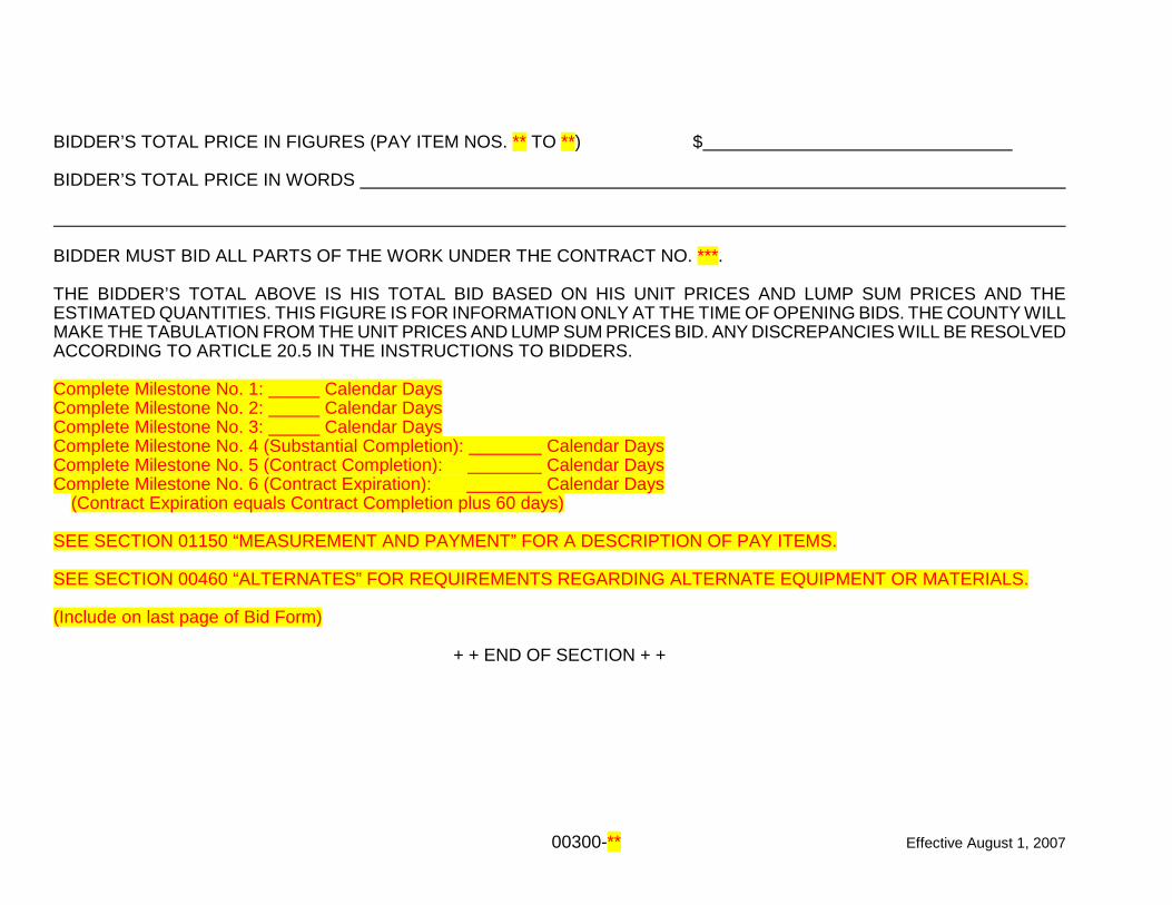
BIDDER’S TOTAL PRICE IN FIGURES (PAY ITEM NOS. ** TO **) $ BIDDER’S TOTAL PRICE IN WORDS BIDDER MUST BID ALL PARTS OF THE WORK UNDER THE CONTRACT NO. ***. THE BIDDER’S TOTAL ABOVE IS HIS TOTAL BID BASED ON HIS UNIT PRICES AND LUMP SUM PRICES AND THE ESTIMATED QUANTITIES. THIS FIGURE IS FOR INFORMATION ONLY AT THE TIME OF OPENING BIDS. THE COUNTY WILL MAKE THE TABULATION FROM THE UNIT PRICES AND LUMP SUM PRICES BID. ANY DISCREPANCIES WILL BE RESOLVED ACCORDING TO ARTICLE 20.5 IN THE INSTRUCTIONS TO BIDDERS. Complete Milestone No. 1: Calendar Days Complete Milestone No. 2: Calendar Days Complete Milestone No. 3: Calendar Days Complete Milestone No. 4 (Substantial Completion): Calendar Days Complete Milestone No. 5 (Contract Completion): Calendar Days Complete Milestone No. 6 (Contract Expiration): Calendar Days (Contract Expiration equals Contract Completion plus 60 days) SEE SECTION 01150 “MEASUREMENT AND PAYMENT” FOR A DESCRIPTION OF PAY ITEMS. SEE SECTION 00460 “ALTERNATES” FOR REQUIREMENTS REGARDING ALTERNATE EQUIPMENT OR MATERIALS. (Include on last page of Bid Form)
+ + END OF SECTION + +
00410-1 Effective August 1, 2007
SECTION 00410
BID AND PERFORMANCE/PAYMENT BOND (Sec. 153.571 Ohio Revised Code) KNOW ALL MEN BY THESE PRESENTS, that we, the undersigned a Principal, and as Surety, are hereby held and firmly bound unto Montgomery County Board of County Commissioners hereinafter called the Obligee, in the penal sum of the dollar amount of the bid submitted by the Principal to the Obligee on , 20 , to undertake the project known as the Project Name. The penal sum referred to herein shall be the dollar amount of the Principal's bid to the Obligee, incorporating any additive or deductive alternate proposals made by the Principal on the date referred to above to the Obligee, which are accepted by the Obligee. In no case shall the penal sum exceed the amount of _________________________________________ dollars ($ ). (If the foregoing blank is not filled in, the penal sum will be the full amount of the Principal's bid, including alternates. Alternatively, if the blank is filled in, the amount stated must not be less than the full amount of the bid, including alternates, in dollars and cents. A percentage is not acceptable.) For the payment of the penal sum well and truly to be made, we hereby jointly and severally bind ourselves, our heirs, executors, administrators, successors, and assigns. THE CONDITION OF THE ABOVE OBLIGATION IS SUCH, that whereas the above named Principal has submitted a bid for the above referred to project: NOW, THEREFORE, if the Obligee accepts the bid of the Principal and the Principal fails to enter into a proper contract in accordance with the bid, plans, details, specifications, and bills of material; and in the event the Principal pays to the Obligee the difference not to exceed ten (10) percent of the penalty hereof between the amount specified in the bid and such larger amount for which the Obligee may in good faith contract with the next lowest bidder to perform the work covered by the bid; or in the event the Obligee does not award the contract to the next lowest bidder and resubmits the project for bidding, the Principal pays to the Obligee the difference not to exceed ten (10) percent of the penalty hereof between the amount specified in the bid, or the costs, in connection with the
00410-2 Effective August 1, 2007
resubmission, of printing new contract documents, required advertising and printing and mailing notices to prospective bidders, whichever is less, then this obligation shall be void, otherwise to remain in full force and effect. If the obligee accepts the bid of the Principal and the Principal within ten (10) days after the awarding of the contract, enters into a proper contract in accordance with the bid, plans, details, specifications, and bills of material, which said contract is made a part of this bond the same as though set forth herein; and IF THE SAID Principal shall well and faithfully perform each and every condition of such contract; and indemnify the Montgomery County Board of County Commissioners against all damage suffered by failure to perform such contract according to the provisions thereof and in accordance with the plans, details, specifications, and bills of material therefor; and shall pay all lawful claims of subcontractors, materialmen, and laborers, for labor performed and materials furnished in the carrying forward, performing, or completing of said contract, we agreeing and assenting that this undertaking shall be for the benefit of any materialmen or laborer having a just claim, as well as for the Obligee herein; then this obligation shall be void; otherwise the same shall remain in full force and effect; it being expressly understood and agreed that the liability of the Surety for any and all claims hereunder shall in no event exceed the penal amount of this obligation as herein stated. THE SAID Surety hereby stipulates and agrees that no modifications, omissions, or additions, in or to the terms of the said contract or in or to the plans and specifications therefor shall in any wise affect the obligations of said Surety on this bond, and it does hereby waive notice of any such modifications, omissions or additions to the terms of the contract or to the work or to the specifications. SIGNED AND SEALED this _____ day of ____________________, A.D. 20___. PRINCIPLE: BY: (Signature)
(Typed or Printed Name) TITLE: SURETY: BY: (Attorney/Attorney-in-Fact Signature*)
(Typed or Printed Attorney/Attorney-in-Fact Name*)
00410-3 Effective August 1, 2007
* Attach certified and effective dated copy of power of attorney showing authority of attorney-in-fact to execute in behalf of corporation. Sec. 9.32 of the Ohio Revised Code requires awarding authorities to simulta-neously with notice of award to contractor, to give written notice to Surety and Agent. Show name and mailing addresses of both Agent and Surety. SURETY COMPANY ADDRESS: SURETY AGENT'S NAME AND ADDRESS:
+ + END OF SECTION + +
00420-1 Effective August 1, 2007
SECTION 00420 BIDDER'S QUALIFICATION STATEMENT (Completion of this statement is required and must be submitted with the Bid in order to qualify for consideration for award of contract.) SUBMITTED TO: BOARD OF COUNTY COMMISSIONERS MONTGOMERY COUNTY, OHIO MONTGOMERY COUNTY ADMINISTRATION BUILDING 451 WEST THIRD STREET DAYTON, OHIO 45422 SUBMITTED FOR: MONTGOMERY COUNTY, OHIO
PROJECT NAME CONTRACT NO. ***
PROJECT NO. *********
SUBMITTED BY:
Name: ________________________________________________________________ (Print or Type Name of Bidder)
A Corporation/A Partnership/An Individual
Address: ________________________________________________________________ ________________________________________________________________ Commissioners: The undersigned certifies under oath the truth and correctness of all statements and of all answers to questions made hereinafter. (Note: Attach Separate Sheets as Required)
00420-2 Effective August 1, 2007
1.0 How many years has your organization been in business as a contractor?
__________________________________ 2.0 How many years has your organization been in business under its present
name? _____________________________ 3.0 Has any construction contract to which you have been a party been
terminated by the owner; have you ever terminated work on a project prior to its completion for any reason; has any surety which issued a performance bond on your behalf ever completed the work in its own name or financed such completion on your behalf; has any surety expended any monies in connection with a contract for which they furnished a bond on your behalf? If the answer to any portion of this question is "yes", please furnish details of all such occurrences including name, address, phone number, and contact person of owner, architect or engineer, and surety, and name and date of project.
No ____________
Yes ____________, If yes, attach details described above.
4.0 Has any officer or partner of your organization ever been an officer or partner
of another organization that had any construction contract terminated by the owner; terminated work on a project prior to its completion for any reason; had any surety which issued a performance bond complete the work in its own name or financed such completion; or had any surety expend any monies in connection with a contract for which they furnished a bond? If the answer to any portion of this question is "yes", please furnish details of all such occurrences including name, address, phone number, and contact person of owner, architect or engineer, and surety, and name and date of project.
No ____________
Yes ____________, If yes, attach details described above.
00420-3 Effective August 1, 2007
5.0 List name of project, owner, architect or engineer, contract amount, percent complete and scheduled completion of the major construction projects your organization has in process on this date.
6.0 List name of project, owner, architect or engineer, contract amount,date of
completion and percent of work with own forces of the major projects of the same general nature as this project which your organization has completed in the past five years.
7.0 List name, address and telephone number of a reference for each project
listed under Items 5.0 and 6.0, above. 8.0 List name and construction experience of the principal individuals of your
organization.
00420-4 Effective August 1, 2007
9.0 List the states and categories of construction in which your organization is legally qualified to do business.
10.0 List name, address and telephone number of an individual who represents
each of the following and whom OWNER may contact for a financial reference:
10.1 A surety:
Name
Contact
Address
Phone No.
Financial Reference
10.2 A bank:
Name
Contact
Address
Phone No.
Financial Reference
00420-5 Effective August 1, 2007
10.3 A major material supplier:
Name
Contact
Address
Phone No.
Financial Reference 11.0 Dated at , this
day of , 20 __ .
_________________________________ (Print or Type Name of Bidder)
(Seal, if corporation) By ______________________________ ______________________________
(Title) ------------------------------------(Affidavit for Individual)------------------------------------------ _____________________________ being duly sworn, deposes and says that all of the foregoing qualification information is true, complete, and accurate. ------------------------------------(Affidavit for Partnership)--------------------------------------- ________________________________ being duly sworn, deposes and says that he/she is a member of the partnership of ___________________________ __________________________________________ and that all of the foregoing qualification information is true, complete, and accurate.
00420-6 Effective August 1, 2007
------------------------------------(Affidavit for Corporation)--------------------------------------- ________________________________ being duly sworn, deposes and says that he/she is ______________________ of __________________________
(Full name of Corporation) __________________________________________ and that all of the foregoing qualification information is true, complete, and accurate. ------------------------------------(Affidavit for Joint Venture)------------------------------------- ____ and being duly sworn, deposes and says that they are members of and that all of the foregoing (Full name of Joint Venture) qualification information is true, complete, and accurate. ------------------------------------(Acknowledgment)----------------------------------------------- ________________________________ being duly sworn, deposes and says that he/she is _________________________ of _________________________
(Name of Bidder) _________________________________________; that he/she is duly authorized to make the foregoing affidavit and that he/she makes it on behalf of ( ) himself/herself; ( ) said partnership; ( ) said corporation.
00420-7 Effective August 1, 2007
Signed: (Affiant)
Typed or printed name:
Title: Sworn to and subscribed in my presence this ________________day of ________________, 20____.
(written signature)
(typed or printed name) Notary Public, State of Ohio My commission expires __________ (month, day, year)
Notary Seal
+ + END OF SECTION + +
00460-1 Effective August 1, 2007
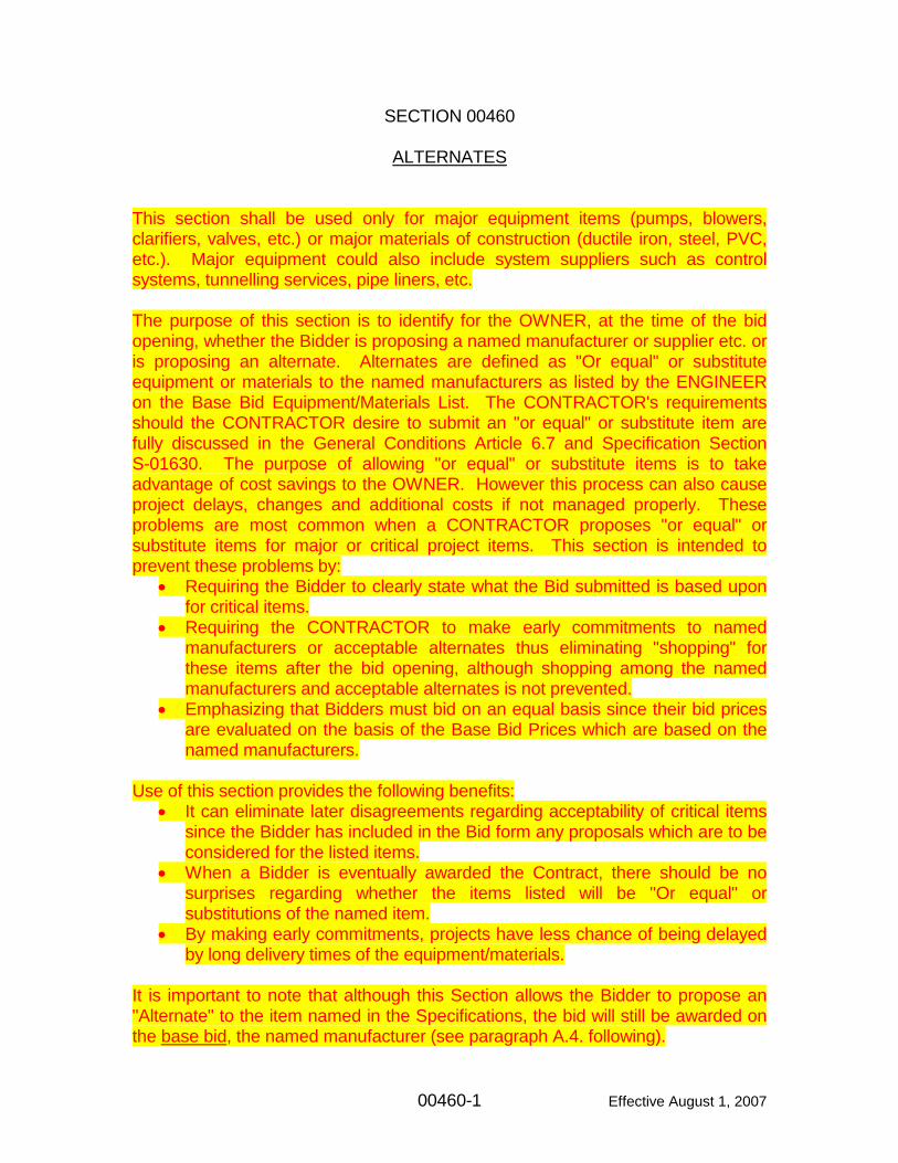
SECTION 00460 ALTERNATES This section shall be used only for major equipment items (pumps, blowers, clarifiers, valves, etc.) or major materials of construction (ductile iron, steel, PVC, etc.). Major equipment could also include system suppliers such as control systems, tunnelling services, pipe liners, etc. The purpose of this section is to identify for the OWNER, at the time of the bid opening, whether the Bidder is proposing a named manufacturer or supplier etc. or is proposing an alternate. Alternates are defined as "Or equal" or substitute equipment or materials to the named manufacturers as listed by the ENGINEER on the Base Bid Equipment/Materials List. The CONTRACTOR's requirements should the CONTRACTOR desire to submit an "or equal" or substitute item are fully discussed in the General Conditions Article 6.7 and Specification Section S-01630. The purpose of allowing "or equal" or substitute items is to take advantage of cost savings to the OWNER. However this process can also cause project delays, changes and additional costs if not managed properly. These problems are most common when a CONTRACTOR proposes "or equal" or substitute items for major or critical project items. This section is intended to prevent these problems by:
• Requiring the Bidder to clearly state what the Bid submitted is based upon for critical items.
• Requiring the CONTRACTOR to make early commitments to named manufacturers or acceptable alternates thus eliminating "shopping" for these items after the bid opening, although shopping among the named manufacturers and acceptable alternates is not prevented.
• Emphasizing that Bidders must bid on an equal basis since their bid prices are evaluated on the basis of the Base Bid Prices which are based on the named manufacturers.
Use of this section provides the following benefits:
• It can eliminate later disagreements regarding acceptability of critical items since the Bidder has included in the Bid form any proposals which are to be considered for the listed items.
• When a Bidder is eventually awarded the Contract, there should be no surprises regarding whether the items listed will be "Or equal" or substitutions of the named item.
• By making early commitments, projects have less chance of being delayed by long delivery times of the equipment/materials.
It is important to note that although this Section allows the Bidder to propose an "Alternate" to the item named in the Specifications, the bid will still be awarded on the base bid, the named manufacturer (see paragraph A.4. following).
00460-2 Effective August 1, 2007
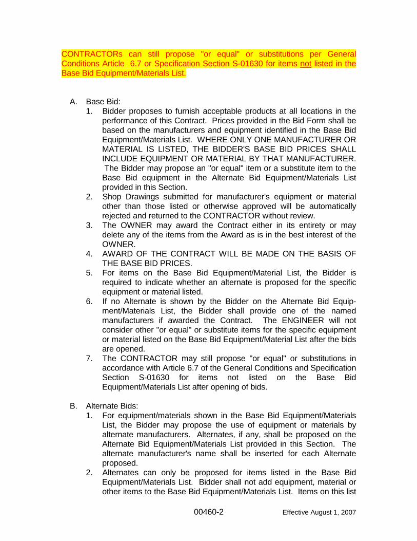
CONTRACTORs can still propose "or equal" or substitutions per General Conditions Article 6.7 or Specification Section S-01630 for items not listed in the Base Bid Equipment/Materials List.
A. Base Bid: 1. Bidder proposes to furnish acceptable products at all locations in the
performance of this Contract. Prices provided in the Bid Form shall be based on the manufacturers and equipment identified in the Base Bid Equipment/Materials List. WHERE ONLY ONE MANUFACTURER OR MATERIAL IS LISTED, THE BIDDER'S BASE BID PRICES SHALL INCLUDE EQUIPMENT OR MATERIAL BY THAT MANUFACTURER. The Bidder may propose an "or equal" item or a substitute item to the Base Bid equipment in the Alternate Bid Equipment/Materials List provided in this Section.
2. Shop Drawings submitted for manufacturer's equipment or material other than those listed or otherwise approved will be automatically rejected and returned to the CONTRACTOR without review.
3. The OWNER may award the Contract either in its entirety or may delete any of the items from the Award as is in the best interest of the OWNER.
4. AWARD OF THE CONTRACT WILL BE MADE ON THE BASIS OF THE BASE BID PRICES.
5. For items on the Base Bid Equipment/Material List, the Bidder is required to indicate whether an alternate is proposed for the specific equipment or material listed.
6. If no Alternate is shown by the Bidder on the Alternate Bid Equip-ment/Materials List, the Bidder shall provide one of the named manufacturers if awarded the Contract. The ENGINEER will not consider other "or equal" or substitute items for the specific equipment or material listed on the Base Bid Equipment/Material List after the bids are opened.
7. The CONTRACTOR may still propose "or equal" or substitutions in accordance with Article 6.7 of the General Conditions and Specification Section S-01630 for items not listed on the Base Bid Equipment/Materials List after opening of bids.
B. Alternate Bids:
1. For equipment/materials shown in the Base Bid Equipment/Materials List, the Bidder may propose the use of equipment or materials by alternate manufacturers. Alternates, if any, shall be proposed on the Alternate Bid Equipment/Materials List provided in this Section. The alternate manufacturer's name shall be inserted for each Alternate proposed.
2. Alternates can only be proposed for items listed in the Base Bid Equipment/Materials List. Bidder shall not add equipment, material or other items to the Base Bid Equipment/Materials List. Items on this list
00460-3 Effective August 1, 2007
were selected by the ENGINEER and are not subject to revision or change by the Bidder.
3. If the Bidder proposes Alternates, it shall include with its Bid, three (3) copies of sufficient technical data to compare the Alternate with the Specifications and Drawings, and to identify any modification to the Design that would be required as a result of the OWNER accepting the Alternate pursuant to General Conditions Article 6.7 and Section S-01630. The Bidder shall also submit three (3) copies of documentation on financial ability of the manufacturer, past history of the manufacturer, locations of successful installations of the proposed alternate, or other documentation as specified in the Bidding Documents for the proposed alternate. The manufacturer of the proposed alternate shall certify in writing and the Bidder shall submit with its bid the following documentation: a. The equipment or material is suitable for the intended application
and duty. b. That equipment or material can and will conform to the
requirements of the specification pertaining to it. 4. Unit or lump sum prices shall be expressed in figures as an add (+) or
deduct (-) to the Base Bid prices. Individual unit or lump sum prices for labor and material shall govern over totals. Failure of the Bidder to submit with its bid the documentation outlined in Paragraph B.2 of this section, or judgment by the ENGINEER that the Alternate is not an "equal" or an acceptable substitute or the documentation submitted with the bid is not complete or inadequate for the ENGINEER to make a determination, one of the named manufacturers shown on the Base Bid Equipment/Materials List shall be furnished. Failure of the Bidder to submit with its bid all the documentation required by Paragraph B.2, of this section or General Conditions Article 6.7 and Section S-01630 will be cause for rejection of the Alternate.
5. The Alternate Cost shall include all modifications necessary to accommodate the Alternate equipment including the cost of redesign and the cost of coordination with other contractors.
6. The Bidder may copy the Alternate Bid Equipment/Materials List page and insert the additional pages in the Bid Submittal Document if required.
7. After review by ENGINEER is complete, OWNER shall make final determination as to the acceptability of all "or equal" or substitution proposals.
00460-4 Effective August 1, 2007
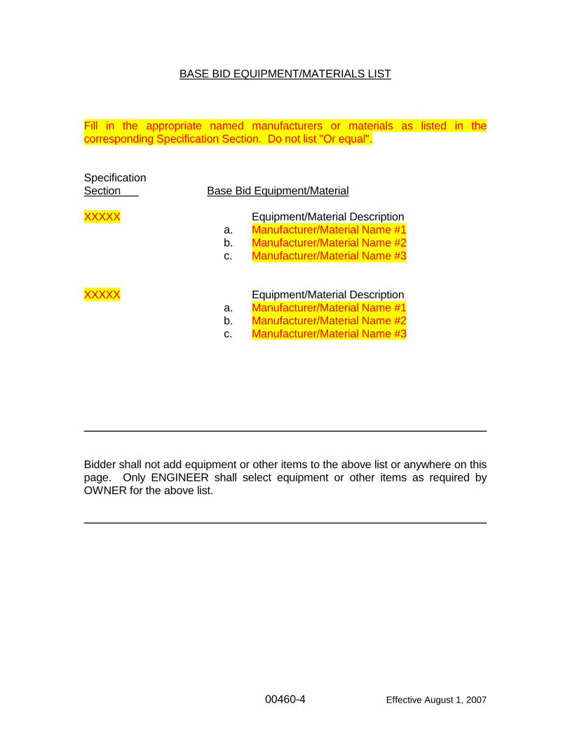
BASE BID EQUIPMENT/MATERIALS LIST Fill in the appropriate named manufacturers or materials as listed in the corresponding Specification Section. Do not list "Or equal". Specification Section Base Bid Equipment/Material XXXXX Equipment/Material Description a. Manufacturer/Material Name #1 b. Manufacturer/Material Name #2 c. Manufacturer/Material Name #3 XXXXX Equipment/Material Description a. Manufacturer/Material Name #1 b. Manufacturer/Material Name #2 c. Manufacturer/Material Name #3 Bidder shall not add equipment or other items to the above list or anywhere on this page. Only ENGINEER shall select equipment or other items as required by OWNER for the above list.
00460-5 Effective August 1, 2007
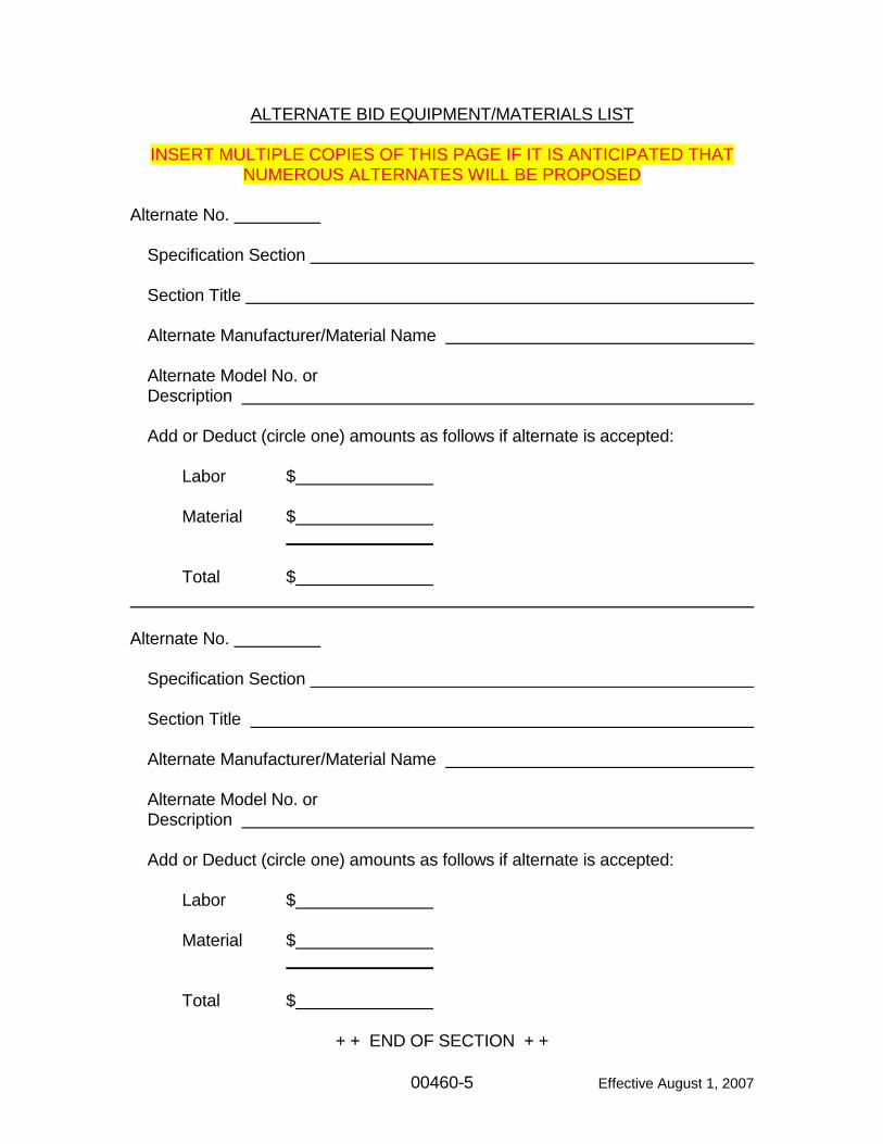
ALTERNATE BID EQUIPMENT/MATERIALS LIST
INSERT MULTIPLE COPIES OF THIS PAGE IF IT IS ANTICIPATED THAT NUMEROUS ALTERNATES WILL BE PROPOSED
Alternate No.
Specification Section Section Title Alternate Manufacturer/Material Name Alternate Model No. or Description Add or Deduct (circle one) amounts as follows if alternate is accepted: Labor $ Material $ Total $ Alternate No.
Specification Section Section Title Alternate Manufacturer/Material Name Alternate Model No. or Description Add or Deduct (circle one) amounts as follows if alternate is accepted: Labor $ Material $ Total $ + + END OF SECTION + +
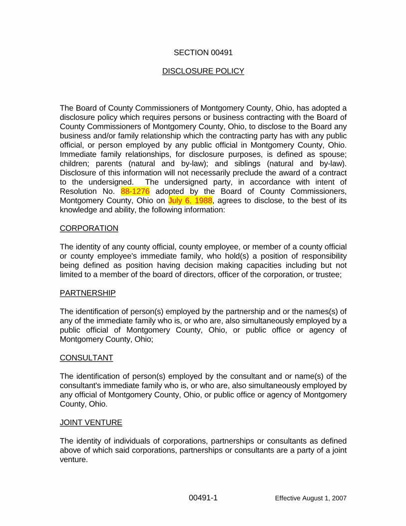
00491-1 Effective August 1, 2007
SECTION 00491 DISCLOSURE POLICY The Board of County Commissioners of Montgomery County, Ohio, has adopted a disclosure policy which requires persons or business contracting with the Board of County Commissioners of Montgomery County, Ohio, to disclose to the Board any business and/or family relationship which the contracting party has with any public official, or person employed by any public official in Montgomery County, Ohio. Immediate family relationships, for disclosure purposes, is defined as spouse; children; parents (natural and by-law); and siblings (natural and by-law). Disclosure of this information will not necessarily preclude the award of a contract to the undersigned. The undersigned party, in accordance with intent of Resolution No. 88-1276 adopted by the Board of County Commissioners, Montgomery County, Ohio on July 6, 1988, agrees to disclose, to the best of its knowledge and ability, the following information: CORPORATION The identity of any county official, county employee, or member of a county official or county employee's immediate family, who hold(s) a position of responsibility being defined as position having decision making capacities including but not limited to a member of the board of directors, officer of the corporation, or trustee; PARTNERSHIP The identification of person(s) employed by the partnership and or the names(s) of any of the immediate family who is, or who are, also simultaneously employed by a public official of Montgomery County, Ohio, or public office or agency of Montgomery County, Ohio; CONSULTANT The identification of person(s) employed by the consultant and or name(s) of the consultant's immediate family who is, or who are, also simultaneously employed by any official of Montgomery County, Ohio, or public office or agency of Montgomery County, Ohio. JOINT VENTURE The identity of individuals of corporations, partnerships or consultants as defined above of which said corporations, partnerships or consultants are a party of a joint venture.
00491-2 Effective August 1, 2007
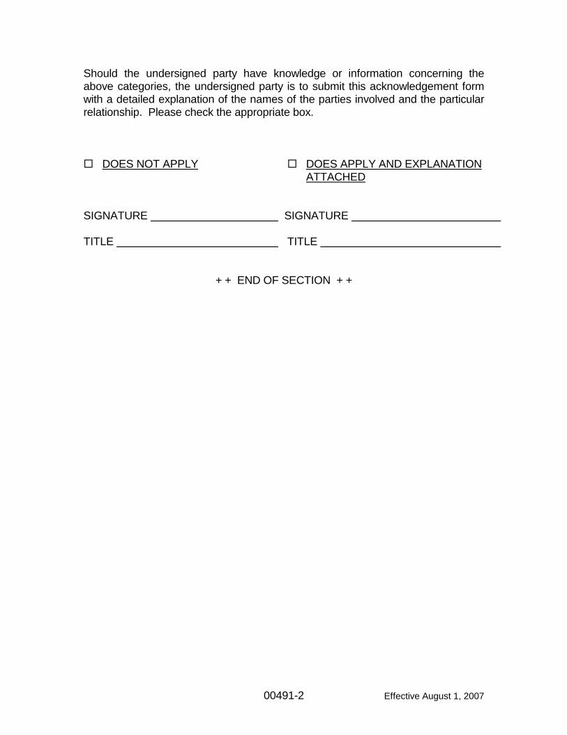
Should the undersigned party have knowledge or information concerning the above categories, the undersigned party is to submit this acknowledgement form with a detailed explanation of the names of the parties involved and the particular relationship. Please check the appropriate box.
DOES NOT APPLY DOES APPLY AND EXPLANATION ATTACHED SIGNATURE SIGNATURE TITLE TITLE + + END OF SECTION + +
MONTGOMERY COUNTY ENVIRONMENTAL SERVICES MASTER TABLE OF CONTENTS
VOLUME 1 - CONSTRUCTION CONTRACT DOCUMENTS
MASTER TOC-1 Effective May 31, 2009
BID SUBMITTAL DOCUMENT (Copy of Bidding Requirements) Page LIST OF FIGURES .................................................................................... LOF-1 LIST OF TABLES ...................................................................................... LOT-1 BIDDING REQUIREMENTS
00020 Notice to Contractors ............................................................. 00020-1 00030 Montgomery County Qualitative Bid Criteria .......................... 00030-1 00100 Instructions to Bidders ........................................................... 00100-1 00300 Bid Form ................................................................................ 00300-1 00410 Bid and Performance/Payment Bond ..................................... 00410-1 00420 Bidder's Qualification Statement ............................................ 00420-1 00460 Alternates ............................................................................... 00460-1 00491 Disclosure Policy .................................................................... 00491-1
Other Applicable Forms required for review of bids CONTRACT FORMS
00500 Notice of Award ...................................................................... 00500-1 00510 Agreement ............................................................................ 00510-1 00511 Escrow Agreement ................................................................. 00511-1 00520 Notice to Proceed .................................................................. 00520-1 00530 Notice of Commencement for Public Improvement ............... 00530-1 00610 Performance/Payment Bond .................................................. 00610-1 00660 Delinquent Personal Property Tax Affidavit ........................... 00660-1 00661 Non-Collusion Affidavit (Principal Contractor) ........................ 00661-1 00662 Non-Collusion Affidavit (Subcontractor) ................................. 00662-1 00663 Construction Contract Exemption Certificate ......................... 00663-1 00670 Prevailing Wages Affidavit of Contractor ............................... 00670-1 00680 Contractor's Affidavit .............................................................. 00680-1 00681 Release of Lien Affidavit ........................................................ 00681-1 00682 Prime Contractor's Affidavit .................................................... 00682-1
Other Forms MISCELLANEOUS FORMS
DRUG-FREE WORKPLACE COMPLIANCE AFFIDAVIT FORM
MONTGOMERY COUNTY ENVIRONMENTAL SERVICES MASTER TABLE OF CONTENTS
VOLUME 1 - CONSTRUCTION CONTRACT DOCUMENTS
MASTER TOC-2 Effective May 31, 2009
MISCELLANEOUS FORMS (continued) CERTIFICATION STATEMENT MONTGOMERY COUNTY VENDOR APPLICATION FIELD ORDER FORM CERTIFICATE OF SUBSTANTIAL COMPLETION
OTHER FORMS CONDITIONS OF THE CONTRACT Page
Index to General Conditions ................................................... IGC-1 00700 General Conditions ................................................................ 00701-1 00800 Supplementary Conditions ..................................................... 00800-1 00830 Prevailing Rates of Wage ...................................................... 00830-1
WPCLF FORMS STORMWATER PERMIT FORMS
01000-1 Effective May 31, 2009
SECTION 01000 GENERAL REQUIREMENTS PART 1 – GENERAL 1.1 DEFINITIONS
A. The following definitions are provided for use with the Montgomery County Water Services Standard Specifications. I f a set of Contract Documents directly includes or makes an indirect reference or appeal to the Montgomery County Water Services Standard Specifications, the definitions contained in those Contract Definitions shall supersede the definitions contained in this section. Note that capitalization of entire words or individual letters is not intended to convey any information other than the typical meaning of the word or phrase as used throughout the Montgomery County Water Services Standard Specifications.
B. Bid Form: The document used to outline payment quantities and methods
included with the Contract Documents and signed by the CONTRACTOR. C. Contract Documents: Documents including all drawings, specifications, bid
data, forms, agreements, contract conditions, addenda, etc. governing the terms, conditions and scope of the work and providing the required detail for construction as well as administration of the work and def ined in the agreement signed by the CONTRACTOR.
D. Contract Drawings: Information contained, referenced and in any way made
a part of the Contract Documents provided in the form of drawings to describe the required work for a specific project.
E. CONTRACTOR: The person, firm or corporation performing work under an
agreement with the OWNER or under an agreement with another party (e.g. the Montgomery County Engineer, a township, etc.) and whose work, or any part thereof, must by ordinance, law, or regulation comply with the latest version of the Montgomery County Water Services Standard Specifications and the Montgomery County Water Services Rules and Regulations.
F. Details: Sketches, figures and tables included in the Montgomery County
Water Services Standard Specifications. Details may also include sketches and figures shown on the drawings to describe work that is specific to a certain project.
G. Drawings: See Contract Drawings.
01000-2 Effective May 31, 2009
H. ENGINEER: The Sanitary Engineer of Montgomery County, Ohio or the OWNER's duly authorized representative.
I. OWNER: The Board of County Commissioners, Montgomery County, Ohio.
J. Specifications: T he Montgomery County Water Services Standard and
Supplemental Specifications. Specifications is further defined as those portions of the Contract Documents consisting of written technical descriptions of materials, equipment, construction systems, standards, and workmanship as applied to the work and c ertain administrative details applicable thereto. S pecifications shall also include written technical descriptions including detail drawings that are included, referenced and in any way made part of the Contract Documents.
K. Project: An identifying name, title, number or similar description assigned to
reference the work.
L. Work: Any work performed by a CONTRACTOR that modifies, expands or otherwise impacts the Montgomery County water supply or sewage collection and treatment facilities and r equired to be f urnished under the Contract Documents.
M. PROVISIONAL APPROVAL: The Sanitary Engineer of Montgomery County
or duly authorized designee shall have the authority to grant Provisional Approval for modification of the specifications herein. T he Provisional Approval shall be subject to and limited by the conditions contained therein.
1.2 COORDINATION WITH OWNER'S WORKING HOURS
A. All work requiring inspection, attention or presence for any reason of OWNER's personnel shall be performed during Montgomery County Water Services regular working hours. Regular working hours are 7:30 a.m. to 4:00 p.m. Monday through Friday.
B. If CONTRACTOR wishes to perform regular Work at times other than regular
working hours, CONTRACTOR shall be required to pay the OWNER for the services of the Resident Project Representative and the ENGINEER at established rates on record in the office of Montgomery County Water Services.
C. Payment to the OWNER for the above services shall be for a minimum of
eight (8) hours, unless another amount is mutually agreed to by ENGINEER and CONTRACTOR, and be paid by check before 12:00 noon the working day before the planned work is to occur.
D. In the event of an emergency or other unplanned event due to the CON-
TRACTOR's work, negligence or otherwise attributable to the CONTRAC-
01000-3 Effective May 31, 2009
TOR, CONTRACTOR shall submit payment for exact hours of overtime worked by OWNER's personnel the next working day.
E. The CONTRACTOR shall give a minimum of forty-eight (48) hours notice of
intent to work at times other than regular working hours to the Resident Project Representative and ENGINEER.
F. ENGINEER has the right to deny permission, with due cause, for the
CONTRACTOR to work at times other than regular working hours. G. When working within the existing public right-of-way, the CONTRACTOR
shall erect construction signage at limits of work at least ten days in advance of commencement of any work advising of the start date and length of construction.
+ + END OF SECTION + +
01043-1 Effective May 31, 2009
SECTION 01043 COORDINATION WITH OWNER'S OPERATIONS PART 1 – GENERAL 1.1 GENERAL
A. The Montgomery County Water Services, Engineering, Field, and Water Reclamation Services groups, has sole responsibility and authority over the control and operation of all County owned and operated facilities including water mains and services, sewer mains and laterals, pumping stations, water reclamation facilities, valves, meters and other related devices and appurtenances. Operation of existing valves, gates and other items of OWNER's facilities shall only be performed by the OWNER's Engineering, Operations, and Water Reclamation personnel.
B. No work shall be undertaken which would jeopardize the minimum required
operations of County facilities. 1. Bypassing of sewage is strictly prohibited. 2. Connection to or contact with the Montgomery County water supply
system, other than by permit and through devices approved by Montgomery County, is strictly prohibited.
3. All work shall conform to the Montgomery County Water Services Rules and Regulations, latest revision.
C. All work necessary to complete modifications, connections, tie-ins, etc. to
existing Montgomery County facilities shall be done in accordance with permits issued by Montgomery County Water Services. See additional information in Section 01046.
D. CONTRACTOR shall allow full access for OWNER's personnel to all
facilities.
E. All CONTRACTORs shall perform all construction activities so as to avoid interference with operations of the OWNER's facilities and the work of others.
F. OWNER shall have the authority to stop or prohibit Work which would
interfere or jeopardize the continuous and reliable operation of OWNER's facilities.
G. Disturbances to Operations:
1. It is required that the existing and new facilities (as they come on line) operate continuously. Scheduled interruptions of any facility's opera-tions, when allowed by permit, shall be coordinated with the Montgom-
01043-2 Effective May 31, 2009
ery County Water Services, Engineering, Field, and Water Reclamation personnel. Frequency and duration of disturbance to these operations shall be minimized.
2. Unscheduled interruption of operation of OWNER's facilities resulting from construction work under the CONTRACTOR's responsibility are strictly prohibited. If such unscheduled interruption occurs, operation of OWNER's facilities shall be returned at once to normalcy through temporary or permanent means. Temporary corrections shall be made permanent at the next scheduled interruption to operations if practica-ble, or as soon as practicable. All permanent corrections shall meet applicable requirements of OWNER.
3. Equipment and materials to be used for temporary purposes need not be new, but shall be in serviceable condition and installed in a safe manner.
4. Temporary facilities shall be installed so as to minimize interference with construction and to meet OSHA, NEC and any other applicable laws', codes' or regulations' requirements.
5. Relocation of such temporary facilities may be required as construction progresses, the cost of which shall be paid for by the CONTRACTOR.
6. CONTRACTOR shall be liable for all costs and fines resulting from unscheduled interruption of the operation of the OWNER's facilities.
1.2 SEQUENCING AND OPERATIONS
A. General: 1. All new facilities shall be tested and in operating condition before the
final tie-ins are made connecting the new facilities to the existing facilities. Comply with the requirements of Section 01046.
1.3 SUBMITTALS
A. Submit detailed schedule of proposed modifications and connections, including proposed bypasses, shutdowns and tie-ins.
B. Submittal shall include the proposed time and date as well as the anticipated
duration. + + END OF SECTION + +
01045-1 Effective May 31, 2009
SECTION 01045 CUTTING AND PATCHING PART 1 - GENERAL 1.1 SCOPE
A. This Section includes all cutting and patching of all existing Montgomery County facilities, all Work under construction and completed Work in order to: repair damage facilities, accommodate the coordination of Work, install other Work, uncover Work for access, inspection or testing, or similar purposes. CONTRACTOR shall execute all cutting and patching, including excavation, backfill and fitting required to: 1. Remove and r eplace defective Work or Work not acceptable to
OWNER. 2. Remove samples of installed Work as required for testing. 3. Remove all constructions required to provide for specified alteration or
addition to existing Work. 4. Uncover Work to provide for ENGINEER's observation of covered Work
or observation by regulatory agencies having jurisdiction. 5. Connect to completed Work that was not accomplished in the proper
sequence. 6. Remove or relocate existing utilities and pipes which obstruct the Work
in locations where connections must be made. 7. Make connections or alterations to existing or new facilities if approved
by OWNER. 8. Refer to Section 01043, Coordination with OWNER's Operations, and
Section 01046, Connections to Existing Facilities, for Work associated with requirements for keeping facilities in operation.
B. Restore all existing Work to a state equal to that existing prior to cutting but
not less than current standards required by local codes, ordinances, standards or regulations, and restore new Work to the standards of these Specifications.
C. Submittals:
1. Prior to cutting which may affect integrity and function of OWNER'S operations and f acilities or of the Work, submit written notice to the ENGINEER requesting consent to proceed with cutting. Request shall include: a. Identification of Project or Work to be done, including a detailed
location. b. Description of affected Work of CONTRACTOR and W ork of
others. c. Necessity for cutting.
01045-2 Effective May 31, 2009
d. Effect on other Work and on s tructural integrity of the Work and nearby structures.
e. Description of proposed Work. Designate: 1) Scope of cutting and patching. 2) CONTRACTOR, Subcontractor or trade to execute Work. 3) Products proposed to be used. 4) Extent of refinishing. 5) Schedule of operations.
f. Alternatives to cutting and patching, if any. g. Designation of party responsible for cost of cutting and patching.
2. Should conditions of Work, or schedule, indicate change of materials or methods, submit written recommendation to ENGINEER, including: a. Conditions indicating change. b. Recommendations for alternative materials or methods. c. Submittals as required for substitutions.
3. Submit written notice to ENGINEER, designating time Work will be uncovered, to provide for observation. Do not begin cutting or patching operations until authorized by ENGINEER.
4. Obtain required permits from OWNER and c omply with all permit requirements regarding cutting and pat ching or otherwise impacting OWNER's facilities.
D. Provide shoring, bracing and support as required to maintain structural
integrity of OWNER's facilities and Project and protect adjacent Work and structures from damage during cutting and patching. All excavations shall comply with latest requirements of OSHA Standard 29 CFR 1926.650.
E. Conform to the Montgomery County Water Services Standard Specifications
and the Contract Documents for application and installation of materials used for patching.
+ + END OF SECTION + +
01046-1 Effective August 1, 2007
SECTION 01046 CONNECTIONS TO EXISTING FACILITIES PART 1 – GENERAL 1.1 GENERAL
A. Perform all construction necessary to complete connections and tie-ins to existing facilities.
B. Keep existing facilities in operation unless otherwise specifically permitted by
OWNER. Comply with the requirements of Section 01043.
C. All CONTRACTORs shall perform all construction activities so as to avoid interference with operations of OWNER's facilities and the work of others.
D. It is the responsibility of each CONTRACTOR to maintain continuous
operation of existing facilities while working in, on or around these facilities. Each CONTRACTOR shall protect the existing facilities by any means required including sheeting, shoring, bracing, patching, temporary piping, etc., however all means shall comply with OWNER's minimum standards.
1.2 BYPASSING
A. All facilities must remain in operation at all times unless otherwise permitted by OWNER. Bypassing of sewage out of the Montgomery County sanitary sewer system is strictly prohibited. A ll bypasses involving sewage must return sewage to the Montgomery County sanitary sewer system without allowing the sewage to enter the environment. CONTRACTOR shall be liable for all costs and f ines resulting from release of sewage out of the Montgomery County sewer system.
B. If a bypass is required to complete certain segments of Work or to make a
tie-in, the CONTRACTOR shall be responsible for all methods, means and costs including provision of all necessary labor and materials to perform the operation.
C. Unless otherwise specifically permitted or approved by the OWNER, no
interruption in service will be permitted during bypasses or tie-ins. + + END OF SECTION + +
01070-1 Effective August 1, 2007
SECTION 01070 ABBREVIATIONS AND SYMBOLS PART 1 - GENERAL 1.1 ABBREVIATIONS
A. Common abbreviations which may be found in the Specifications are: alternating current A-C ante meridian am ampere A average avg brake horsepower bhp British thermal unit Btu carbonaceous biochemical oxygen demand CBOD Centigrade °C company Co cubic inch cu in cubic foot cu ft cubic yard cu yd cubic feet per minute cfm cubic feet per second cfs decibel dB degrees Celsius (say) 20°C degrees Fahrenheit (say) 68°F diameter dia direct current D-C dollars $ each ea efficiency eff Fahrenheit °F feet ft feet per hour fph feet per minute fpm feet per second fps figure Fig flange flg foot-pound ft-lb gallon gal gallons per minute gpm
gallons per second gps gram g Hertz Hz hour hr horsepower hp inch in. inch-pound in.-lb inside diameter ID kilopascals kPA kilovolt-ampere kVA kilowatt kW kilowatt-hour kWh linear foot lin ft liter l maximum max measure of acidity or alkalinity pH mercury Hg milligram mg milligrams per liter mg/l milliliter ml millimeter mm million gallon mil million gallons per day mgd minimum min National Pipe Threads NPT net positive suction head npsh number No. ounce oz outside diameter OD
01070-2 Effective August 1, 2007
parts per million ppm post meridian pm pound or pounds lb pounds per square foot psf pounds per square inch psi pounds per square inch absolute psia pounds per square inch gage psig revolutions per minute rpm second sec specific gravity sp gr square sq square foot sq ft
square inch sq in square yard sq yd standard std standard cubic feet per minute scfm thousand pounds kip total dynamic head TDH totally-enclosed- fan cooled TEFC volt V wastewater treatment plant wwtp
1.2 ORGANIZATION ABBREVIATIONS A. Abbreviations of organizations which may be used in these Specifications
are:
AASHTO American Association of State Highway and Transportation Officials
ACS American Chemical Society ACI American Concrete Institute AFBMA Anti Friction Bearing Manufacturers Association AGMA American Gear Manufacturers Association AIChE American Institute of Chemical Engineers AISC American Institute of Steel Construction AISI American Iron and Steel Institute ANSI American National Standards Institute APHA American Public Health Association API American Petroleum Institute AREA American Railway Engineering Association ASTM American Society for Testing and Materials ASCE American Society of Civil Engineers ASME American Society of Mechanical Engineers ASHRAE American Society of Heating, Refrigerating and
Air Conditioning Engineers AWWA American Water Works Association AWS American Welding Society CMS Construction and Materials Specifications,
Ohio Department of Transportation CRSI Concrete Reinforcing Steel Institute DIPRA Ductile Iron Pipe Research Association EPA Environmental Protection Agency FM Factory Mutual HEW Department of Health, Education and Welfare
01070-3 Effective August 1, 2007
HUD Department of Housing and Urban Development IEEE Institute of Electrical and Electronic Engineers IRI Industrial Risk Insurance ISA Instrument Society of America ISO Insurance Services Office JIC Joint Industrial Council MCD Miami Conservancy District MIL (STD) Military Standard NAAMM National Association of Architectural Metal
Manufacturers NARUC National Association of Railroad and Utilities
Commissioners NEC National Electric Code NEMA National Electrical Manufacturers Association NFPA National Fire Protection Association NPI National Petroleum Institute NSF National Sanitation Foundation ODOT Ohio Department of Transportation OSHA Occupational Safety and Health Act PCI Precast Concrete Institute SMACNA Sheet Metal and Air Conditioning National
Association SSPC Steel Structures Painting Council UL Underwriters' Laboratories, Inc. USGS United States Geological Survey USPHS United States Public Health Service WEF Water Environment Federation WPCF Water Pollution Control Federation WWEMA Water and Wastewater Equipment Manufacturers
Association 1.3 SYMBOLS A. Refer to symbols used on the Drawings. PART 2 - PRODUCTS (NOT USED)
+ + END OF SECTION + +
PART 3 - EXECUTION (NOT USED)
01072-1 Effective May 31, 2009
SECTION 01072 REFERENCE STANDARDS PART 1 - GENERAL 1.1 SCOPE
A. When a reference standard is specified, comply with requirements and recommendations stated in that standard, except when they are modified by the Montgomery County Water Services Standard Specifications or the Contract Documents, or when applicable laws, ordinances, rules, regulations or codes establish stricter standards. The latest provisions of applicable standards shall apply to the Work, unless otherwise specified. Reference standards include, but are not necessarily limited to, the following: 1. American Association of State Highway and Transportation Officials. 2. American Concrete Institute. 3. American Gear Manufacturers Association. 4. American Institute of Steel Construction. 5. American Iron and Steel Institute. 6. American National Standards Institute. 7. American Petroleum Institute. 8. American Society of Heating, Refrigerating and A ir Conditioning
Engineers. 9. American Society of Mechanical Engineers. 10. American Society for Testing and Materials. 11. American Water Works Association. 12. American Welding Society. 13. Architectural Aluminum Manufacturer's Association. 14. Concrete Reinforcing Steel Institute. 15. Factory Mutual Association. 16. Institute of Electrical and Electronics Engineers. 17. Joint Industrial Council. 18. Miami Conservancy District. 19. National Association of Architectural Metal Manufacturers. 20. National Electrical Code. 21. National Electrical Safety Code. 22. National Electrical Manufacturer's Association. 23. National Fire Protection Association. 24. National Petroleum Institute. 25. Occupational Safety and Health Act. 26. Ohio Basic Building Code. 27. Ohio Department of Transportation, Construction and Material Specifi-
cations. 28. Ohio Revised Code. 29. Prestressed Concrete Institute.
01072-2 Effective May 31, 2009
30. Steel Structures Painting Council. 31. Underwriters' Laboratories, Inc. 32. All other applicable standards listed in the Specifications, and t he
standards of utility service companies, where applicable. PART 2 - PRODUCTS (NOT USED) PART 3 - EXECUTION (NOT USED)
+ + END OF SECTION + +
01150-1 Effective May 31, 2009
SECTION 01150 MEASUREMENT AND PAYMENT PART 1 - GENERAL 1.1 DESCRIPTION
A. CONTRACTOR shall furnish all labor, materials, tools, equipment, appurtenances and all services necessary to perform all Work required at the CONTRACTOR's lump sum or unit prices listed herein and/or on the Bid Form.
B. No direct or separate payment will be made for providing miscellaneous
temporary or accessory work, plants, services, CONTRACTOR's field offices, layout surveys, job signs, sanitary requirements, testing, safety devices, approval and record drawings, water supplies, power, maintaining traffic, removal of waste, watchmen, bonds, insurance, etc. unless specifically listed on the Bid Form, this Section or requested by the ENGINEER. Compensa-tion for all such services, items and m aterials shall be i ncluded in the CONTRACTOR's prices bid for the lump sum and unit price pay items listed herein and/or on the Bid Form.
C. Each lump sum and uni t bid price will be deemed to include an amount
considered by CONTRACTOR to be adequate to cover CONTRACTOR's overhead and profit for each separately identified item.
1.2 ENGINEER'S ESTIMATE OF QUANTITIES
A. ENGINEER's estimated quantities for unit price pay items, as listed in the Bid Form, are approximate only. OWNER does not expressly or by implication agree that the nature of the materials encountered below the surface of the ground or the actual quantities of material encountered or required will correspond therewith and reserves the right to increase or decrease any quantity or to eliminate any quantity as OWNER may deem necessary.
1.3 UNIT PRICE WORK
A. General: All payments shall be based on the as-built measurements.
B. Rock Excavation: Unless otherwise shown on the Bid Form, the payment for rock excavation, as defined in the Montgomery County Water Services Standard Specification Section 02211, shall be made on the actual number of cubic yards measured along the centerline of the pipe and as described in Section 02211. The unit price bid shall include all work as required by Section 02211. Should rock be encountered and no estimated quantities
01150-2 Effective May 31, 2009
were shown on the Bid Form, payment will be made at $60.00 per cubic yard (which shall be considered adequate for all work required by Section 02211 including all overhead and profit).
C. Unsuitable Soil: If, as determined by the ENGINEER, the material at or
below the grade of the bottom of a trench or other excavation is unsuitable as a foundation for its intended purpose, it shall be removed to such depths and widths as ENGINEER may direct and be r eplaced by the CONTRACTOR with approved materials. Payment for this work will be made on a lineal foot price bid on one (1) foot increments of fill for various size pipe unless otherwise stated in the Bid Form. I f not listed on t he Bid Form, CONTRACTOR shall be paid a negotiated amount.
D. Pressure Pipe and Services (Water):
1. Valves: Unless otherwise shown on the Bid Form, main line valves shall be inventoried separately for each size and type for payment and the unit price bid for a valve shall include furnishing and installing the valve, valve keys and valve box in conformity with Montgomery County Water Services specifications.
2. Fire Hydrants: Unless otherwise shown on the Bid Form, the unit price bid for a fire hydrant shall include the cost of furnishing and installing the fire hydrant in accordance with Montgomery County Water Services specifications and payment shall be m ade on t he actual number of hydrants installed.
3. Pressure Water Service Lines: a. Accessories: Unless otherwise shown on the Bid Form, the unit
price for accessories for a water service shall include the cost of furnishing and installing a corporation stop in the main line under pressure and furnishing and installing a curb stop with a curb box. The water service accessory unit shall be inventoried for payment as to the number of units actually installed in the various size classifications. 1) Taps: All taps to existing water mains are to be made under
the authority of the required permit issued by the authority having jurisdiction. Taps can be made by Montgomery County or the CONTRACTOR at the CONTRACTOR's option and expense, however service line and f ire line taps are to be made by the City of Dayton if in the City of Dayton's jurisdic-tion. All taps are to be pai d for by the CONTRACTOR at prevailing established prices on f ile at the County or City offices. This cost shall be included in the CONTRACTOR's unit price bid for accessories unless otherwise shown on the Bid Form. Note that some pipe materials such as concrete pressure pipe require special manufacturer's services for tapping. CONTRACTOR shall include all costs for such services in the price bid for accessories.
01150-3 Effective May 31, 2009
b. Pipe: Unless otherwise shown on the Bid Form, the unit price for water service pipe shall include the cost of furnishing and installing the water service pipe and the restoration of all surfaces, areas or other items disturbed by the construction of the water service pipe. Payment shall be made on the actual number of lineal feet of water service pipe installed in the various size classifications as measured along the restored ground profile from the centerline of the main to the curb stop. 1) Excavation and Backfill: Unless otherwise shown on the Bid
Form, the unit price for a water service pipe shall include the cost of excavation (other than rock) and bac kfilling of the trench with excavated material. If the water service is within a dedicated right-of-way, roadway, drive or parking area, the unit price for water service pipe shall include the cost of excavation, disposing of excavated material and backfilling the trench with gravel backfill or controlled density fill as shown on the drawings or otherwise required.
2) Testing and Disinfection: Unless otherwise shown on the Bid Form, the cost of testing and disinfection of the service line shall be included in the testing and disinfection costs for the Water Main pipe.
4. Pressure Water Mains: a. Pipe: Unless otherwise shown on the Bid Form, the unit price bid
for each type, size and class of water main pipe shall include the cost of furnishing and installing the water main pipe including all pipe fittings, restraint systems, or anchoring products specified, or shown on the drawings or otherwise required. The length of water main to be used as a basis of payment shall be the actual field measurement taken along the centerline of each type, size and class of pipe as measured along the restored ground profile. The measurement shall be through all valves and fittings installed in the pipe line. 1) Excavation and Backfill: Unless otherwise shown on the Bid
Form, the unit price for each type, size and class of water main pipe shall include the cost of excavation (other than rock) and backfilling with excavated material; or excavation and disposal of excavated material and bac kfilling with gravel backfill or controlled density fill as specified, or shown on the drawings or otherwise required.
2) Testing and Disinfection: Unless otherwise shown on the Bid Form, the cost of testing and disinfection of the pipe shall be included in the unit price bid for the pipe.
b. Taps: All taps to existing water mains are to be made under the authority of the required permit issued by the authority having jurisdiction. T aps can be made by Montgomery County or the CONTRACTOR at the CONTRACTOR's option and ex pense, however service line and fire line taps are to be made by the City of
01150-4 Effective May 31, 2009
Dayton if in the City of Dayton's jurisdiction. All taps are to be paid for by the CONTRACTOR at prevailing established prices on file at the County or City offices. This cost shall be included in the CONT-RACTOR's unit price bid unless otherwise shown on the Bid Form. Note that some pipe materials such as concrete pressure pipe require special manufacturer's services for tapping. CONTRACTOR shall include all costs for such services in the price bid.
E. Gravity Pipe and Services (Sewer):
1. Gravity Sewer Service Lines: a. Service Connections: Unless otherwise shown on the Bid Form,
the unit price for a service wye branch or tee shall be the extra cost over the main line cost to furnish and install the wye branch or tee and stopper. T he CONTRACTOR shall be pai d for the actual number of each size wye branch or service tee and s topper installed based on the unit prices stated on the Bid Form.
b. Pipe: Unless otherwise shown on the Bid Form, the unit price for gravity service line pipe shall include the cost of furnishing and installing the pipe and restoration of all surfaces, areas or other items disturbed by the construction of the gravity service line. Payment shall be made on the actual number of lineal feet installed for the various size classifications. The measurement for payment shall be the distance measured along the restored ground profile between the centerline of the main line sewer to a point one (1) foot beyond the road right-of-way limit or easement as shown on the drawings or any other extremity as designated by the ENGINEER. 1) Excavation and Backfill: Unless otherwise shown on the Bid
Form, the unit price for a gravity service line pipe shall include the cost of excavation (other than rock) and backfilling of the trench with pipe bedding and with excavated material. If the gravity service is within a dedicated right-of-way, roadway, drive or parking area, the unit price for gravity service pipe shall include the cost of excavation, disposing of excavated material and bac kfilling the trench with gravel backfill or controlled density fill as shown on the drawings or otherwise required.
2) Testing: Unless otherwise shown on the Bid Form, the cost of testing the service line shall be included in the testing costs for the gravity sewer pipe.
2. Gravity Sewer Pipe: a. Pipe: Unless otherwise shown on the Bid Form, the unit price for
each size and type of gravity sewer pipe shall include the cost of all labor and material required to furnish, install and test the sewer pipe and fittings. Measurement for payment shall be made along the centerline of the sewer along the restored ground profile. The
01150-5 Effective May 31, 2009
measurement shall be continuous through all special fittings, manholes, and other structures requiring channel pipe. 1) Testing: The cost of testing the pipe shall be included in the
unit price bid for the pipe. b. Excavation and Backfill: Unless otherwise shown on the Bid Form,
the unit price for trench excavation and backfill shall include the cost of excavation (other than rock) and bac kfilling with pipe bedding and with excavated material. Payment shall be made on the actual number of lineal feet of trench excavated as measured along the trench centerline for the various pipe sizes and depth classifications stated on the Bid Form. 1) Unless otherwise shown on the Bid Form or otherwise stated in
the Contract Documents, the depth of the sewer trench excavation shall be measured from the profile of the surface of the original ground to the bottom of the excavation as specified and shall include the depth (thickness) of rock excavation in the trench. The depth of rock excavation shall be included in the payment for rock excavation as specified in this Section.
2) Unless otherwise shown on the Bid Form, sewer pipe trench excavation shall be classified in two (2) feet increments from initial depth, unless the construction of the sewers are a portion of a lump sum type bid.
3) Unless otherwise shown on the Bid Form, the unit price for sewer pipe trench excavation and backfill shall also include all costs for disposal of excavated material and backfilling the trench with gravel backfill or controlled density fill as required by the Specifications, where shown on t he drawings or otherwise required.
3. Encasement: a. Unless otherwise shown on the Bid Form, the measurement for
concrete pipe encasement shall be the actual number of lineal feet measured along the centerline of the pipe as specified at the width and depth and height as shown on the construction drawings for each pipe encasement. The unit cost shall include furnishing and placing the pipe encasement. The CONTRACTOR shall be paid for the actual lineal feet of encasement at the unit price quoted on the Bid Form.
F. Lump Sum Items:
1. Whenever a construction item that requires excavation and backfill is bid on a lump sum basis, the price shall include all work specified to be done on an itemized basis.
2. When a pressure or gravity system is a par t of a l ump sum type proposal, the price quoted shall include the cost of furnishing all labor and material to construct the pressure or gravity system in accordance with these specifications.
01150-6 Effective May 31, 2009
G. Casing Pipe or Tunnel Liner: 1. Unless otherwise shown on the Bid Form, the payment for installation of
casing pipe or tunnel liner, bulkheads and all work required by Section 02600 (including all material installed between the casing pipe or tunnel liner and the carrier pipe) will be made on the actual number of lineal feet of the various type product installed. The unit price per foot for casing pipe or tunnel liner shall include furnishing all materials and installing the pipe by either jacking, boring or tunneling. T he construction of the approach pits with all necessary sheeting, shoring, dewatering, etc. and all other incidentals required to complete the installation including any soil stabilization work shall also be included in the unit price.
H. Manhole:
1. Unless otherwise shown on the Bid Form, the unit price for a standard manhole shall include the cost of all labor and m aterial required to complete the standard manhole as specified and s hown on the drawings. The CONTRACTOR shall be paid for the actual number of standard manholes installed at the unit price bid on the Bid Form.
2. Unless otherwise shown on the Bid Form, the unit additional cost for a watertight manhole shall include furnishing and installing a watertight manhole frame and cover with cover bolts, gaskets and frame anchor bolts in place of the standard manhole frame and cover as specified. The CONTRACTOR shall be paid for the actual number of watertight manholes installed at the unit price bid on the Bid Form.
3. Unless otherwise shown on the Bid Form, the unit price for manhole drop connections shall include the cost of furnishing and installing the riser pipe and bends, the concrete encasement and any excavation and backfill required to complete the drop connection and the cost of the mainline tee, all in accordance with the specifications. T he CONTRACTOR will be paid for the actual number of drop connections installed at the unit price bid on the Bid Form. There may be more than one (1) drop connection on a single manhole.
4. Unless otherwise shown on the Bid Form, the unit price for a manhole vent pipe assembly shall include the cost of furnishing and installing the pipe and fittings and all excavations and backfilling as specified and to the lengths and heights shown or required for proper installation and operation of the assembly. The CONTRACTOR shall be paid for the actual number of manhole vent pipe assemblies installed at the unit price bid on the Bid Form.
5. Unless otherwise shown on the Bid Form, the unit price for a manhole groundwater level monitoring pipe assembly shall include the cost of furnishing and installing the pipe and f ittings and all excavations and backfilling as specified and to the lengths and heights shown or required for proper installation and operation of the assembly. The CONTRAC-TOR shall be paid for the actual number of manhole groundwater level
01150-7 Effective May 31, 2009
monitoring pipe assemblies installed at the unit price bid on the Bid Form.
6. Testing: Unless otherwise shown on the Bid Form, the cost of testing each manhole shall be included in the unit price bid for each type and size of manhole.
+ + END OF SECTION + +
01201-1 Effective August 1, 2007
SECTION 01201 PRECONSTRUCTION CONFERENCE PART 1 - GENERAL 1.1 SCOPE
A. Date, Time and Location: Conference will be held after execution of the Agreement and before construction is started at the site. The ENGINEER will fix the date, time and l ocation of the meeting in accordance with Paragraph 2.7 of the General Conditions.
B. The ENGINEER shall prepare agenda, preside at meeting, and pr epare
and distribute a transcript of proceedings to all parties. C. All prime CONTRACTORS shall provide data required, contribute
appropriate items for discussion, and be pr epared to discuss all items on agenda.
1.2 REQUIRED ATTENDANCE
A. CONTRACTOR(S) and major Subcontractors. B. ENGINEER. C. ENGINEER's Consultants. D. Representatives of governmental agencies and ut ilities having any degree
of regulatory authority, control or responsibility, if available. 1.3 AGENDA
A. Agenda will include, but will not necessarily be limited to, the following: 1. Project Administration:
a. Designation of responsible personnel. List all names, titles, affiliations, work phone numbers and emergency phone numbers.
b. Role of OWNER and ENGINEER in supervising project. c. Define communication flow.
2. Status of Contracts: a. Agreements executed. b. Bonds submitted and approved. c. Notice to proceed. d. Establish completion date.
3. Subcontractors. 4. Coordination with other contractors.
01201-2 Effective August 1, 2007
5. Coordination with OWNER's operations. 6. Construction schedule. 7. Processing of Shop Drawings.
a. Discuss submission of samples. 8. Schedule of Shop Drawing submittals. 9. Testing:
a. Factory witness tests required by CONTRACTOR, paid by OWNER.
b. Factory witness tests required by CONTRACTOR, paid by CONTRACTOR.
c. Frequency and schedule of field tests; equipment, pipe, etc. d. Frequency and schedule of material tests; concrete, soil,
compaction, etc. 10. Processing of Field Orders and Amendments. 11. Requirements for copies of Contract Documents. 12. Insurance in force. 13. Schedule of values. 14. Processing of progress payments.
a. Submittal of Prevailing Wage Rate reports. b. Submittal of affidavits of payment to employees, subcontractors
and suppliers. 15. Record Documents:
a. CONTRACTOR to keep record drawing set current at site and available to Inspector, ENGINEER, OWNER, etc.
b. CONTRACTOR to deliver record set at end of project. c. CONTRACTOR shall be responsible for record drawing informa-
tion. 16. CONTRACTOR(S)' responsibility for safety and f irst aid procedures.
CONTRACTOR to provide list of all emergency contacts and phone numbers.
17. Security: a. Review approved Security Plan (if required by Section S-01540). b. Identify effective dates of Security Plan. c. Identify personnel (OWNER, CONTRACTOR, subcontractor, etc.)
authorized to enter project site. d. Identify site entrance points and exit points if applicable.
18. Use of premises. 19. Clean-up/housekeeping considerations.
a. Daily clean-up is required in Section 01710. 20. Field Offices. 21. Facilities provided by CONTRACTOR:
a. Restroom facilities, drinking water. b. Telephone. c. Temporary Electric. d. Emergency and safety facilities.
22. Utility Considerations: a. Coordination with Electric Utilities.
01201-3 Effective August 1, 2007
b. Coordination with Water Utilities. c. Future utilities that must cross site. d. Coordination with Telephone, Gas, Cable, etc.
23. Staking and Layout: a. Reference points, benchmarks provided by OWNER. b. Method of staking and layout to be employed by CONTRACTOR. c. Discuss staking and clearing procedures. d. Anticipated schedule for clearing procedures.
24. Earthwork excavation: a. Plan for compliance with OSHA standards (see Section 02221 for
references, submittals, etc.). b. Trench excavations impacting streets, driveways and roadways
must be completed as stated in Section 02221. c. Cut/Fill balance. d. Submission of materials from another site, approval of site. e. Discharge of dewatering flows (See Section 02221). f. Debris removal.
25. Utilization of the site for storage, vehicle parking, access routes and other site requirements.
26. Required Permits: a. Earthmoving; ODNR permits. b. Roadway permits. c. Other permits.
27. Proposed haul routes, access routes, traffic control plans, etc. 28. Stream Protection Measures (if applicable):
a. Impacts of site utilization (Item 25) and traffic/haul concerns (Item 27).
b. Protection of vegetation, trees, etc. c. Proposed stream crossing construction plan. d. Proposed temporary culverts, bridges, etc., if any. e. Restoration procedures, staged to minimize impact. f. Other issues as necessary.
29. Stormwater Management Plan: a. Erosion control measures. b. Status of permit. c. Other issues as necessary.
PART 2 - PRODUCTS (NOT USED) PART 3 - EXECUTION (NOT USED)
+ + END OF SECTION + +
01202-1 Effective August 1, 2007
SECTION 01202 PROGRESS MEETINGS PART 1 - GENERAL 1.1 SCOPE
A. Date and Time: 1. Regular Meetings: As mutually agreed upon by the ENGINEER and
CONTRACTOR. 2. Other Meetings: On call.
B. Place: General CONTRACTOR's office at Project site or other mutually
agreed upon location.
C. The ENGINEER shall prepare agenda, preside at meetings, and prepare and distribute a transcript of proceedings to all parties.
D. Each CONTRACTOR shall provide data required and be prepared to
discuss all items on agenda. 1.2 MINIMUM ATTENDANCE
A. Prime CONTRACTORS: 1. When needed f or the discussion of a par ticular agenda item, Prime
CONTRACTORS shall require representatives of Subcontractors or suppliers to attend a meeting.
B. ENGINEER.
C. ENGINEER's Consultants. D. Others as appropriate. E. Representatives present for each party shall be authorized to act on their
behalf. 1.3 AGENDA
A. Agenda will include, but will not necessarily be limited to, the following: 1. Transcript of previous meeting. 2. Progress since last meeting. 3. Planned progress for next period. 4. Problems, conflicts and observations.
01202-2 Effective August 1, 2007
5. Change Orders. 6. Applications for payment. 7. Status of Shop Drawings. 8. Quality standards and control. 9. Schedules, including off-site fabrication and del ivery schedules.
Corrective measures required. 10. Coordination between parties. 11. Safety. 12. Other business.
PART 2 - PRODUCTS (NOT USED) PART 3 - EXECUTION (NOT USED)
+ + END OF SECTION + +
01310-1 Effective August 1, 2007
SECTION 01310 CONSTRUCTION SCHEDULES PART 1 - GENERAL 1.1 GENERAL
A. Provide construction schedule which conforms to the requirements below, unless otherwise approved by the ENGINEER.
B. Update schedules every one ( 1) month unless otherwise specified or
directed by the ENGINEER. C. In the preparation of the schedule, the CONTRACTOR shall take into
consideration Shop Drawing submittal and approval time, the delivery times of equipment and materials, Subcontractors' work, availability and abilities of workmen, weather conditions, any restrictions in operations at the Work site, and al l other items that may affect completion of the Work within the time requirements of the Contract Documents.
1.2 CONTENT
A. Shop Drawing submittal dates and required approval dates. B. Product delivery dates. C. Factory and field testing dates. D. Dates for beginning and completing each phase of the Work by activity and
by trades. Include all milestone dates. E. Other data as required by the ENGINEER.
1.3 FORMAT
A. Type: Horizontal bar chart. B. Sheet Size: 24-inches by 36-inches. C. Time Scale: Indicate first date in each work week. D. Organization:
1. Show construction work by activity as the major schedule. 2. Indicate critical activities which dictate rate of progress. 3. Indicate Shop Drawing submittal dates by Specification Number.
01310-2 Effective August 1, 2007
4. Indicate product delivery period after Shop Drawing approval and critical delivery date (latest date that does not impede the rate of work).
E. Activity Designations: Show title and related Specification Section number.
1.4 SUBMITTALS
A. Submit six (6) copies of initial schedule to the ENGINEER at least twenty (20) days prior to submitting first application for a progress payment but no later than twenty-one (21) days after the effective date of the Notice to Proceed.
B. Submit six (6) copies of updated schedules at progress meetings. I f a
schedule remains unchanged from one period to the next, submit a written notice to that effect.
C. Attach a l etter of transmittal to each submittal and i nclude the following
information in the letter: 1. A listing of items which have changed since the last submittal. 2. Discussion of problems causing delays, anticipated length of delays,
and proposed countermeasures.
+ + END OF SECTION + +
01341-1 Effective May 31, 2009
SECTION 01341 SHOP DRAWING PROCEDURES PART 1 - GENERAL 1.1 GENERAL
A. Shop Drawing procedures shall conform to requirements of Paragraphs 6.30 and 6.37 of the General Conditions and as described in this Section.
B. Submit Shop Drawings to the ENGINEER.
C. CONTRACTOR shall furnish required submittals with complete information
and accuracy in order to achieve required approval of an item within three (3) submittals.
D. Shop Drawings shall be s ubmitted well in advance of the need for the
material or equipment for construction and with ample allowance for the time required to make delivery of material or equipment after data covering such is approved. CONTRACTOR shall assume the risk for all materials or equipment which are fabricated or delivered prior to the approval of Shop Drawings. Materials or equipment will not be included in periodic progress payments until approval thereof has been obtained in the specified manner.
E. ENGINEER will review and process all submittals promptly, but a reasonable
time should be allowed for this, for the Shop Drawings being revised and resubmitted, and for time required to return the approved Shop Drawings to CONTRACTOR. The CONTRACTOR should allow thirty (30) days for each submittal review and/or response.
F. It is the CONTRACTOR's responsibility to review submittals made by
CONTRACTOR's suppliers and Subcontractors before transmitting them to the ENGINEER to assure proper coordination of the Work and to determine that each submittal is in accordance with CONTRACTOR's desires and that there is sufficient information about materials and equipment for ENGINEER to determine compliance with the Specifications and with other Contract Documents. I ncomplete or inadequate submittals will be returned for revision without review.
G. In the event the CONTRACTOR obtains the ENGINEER's approval for the
use of equipment or material other than that which is shown or specified, the CONTRACTOR shall, at CONTRACTOR's own expense and using methods approved by the ENGINEER, make all changes to the Work, including structures, piping, electrical, equipment and controls, that may be necessary to accommodate this equipment or material.
01341-2 Effective May 31, 2009
H. Approval of Shop Drawings shall not relieve the CONTRACTOR from the responsibility of furnishing materials and equipment of proper dimension, size, quality, quantity, and performance characteristics to efficiently perform their intended purposes and the requirements and intent of the Specifications and other Contract Documents. A pproval shall not relieve the CONTRACTOR from responsibility for errors of any sort on t he Shop Drawings. A pproval, when provided by ENGINEER, only indicates conformance with the Specifications and other Contract Documents and the design concept of the Project. E ach CONTRACTOR is responsible for dimensions which shall be confirmed and correlated at the job site. Each CONTRACTOR is also responsible for information that pertains solely to the fabrication processes or to the technique of construction and f or the coordination of the Work of all trades.
1.2 PROCEDURE
A. A letter of transmittal shall accompany each submittal. If data for more than one Section of the Specifications is submitted, a separate transmittal letter shall accompany the data submitted for each Section.
B. At the beginning of each letter of transmittal provide a reference heading
indicating the following: 1. Montgomery County Water Services. 2. Project Name . 3. Project No. . 4. Contract No. . 5. Transmittal No. . 6. Specification Section No. .
C. If a Shop Drawing deviates from the requirements of the Specifications or
other Contract Documents, CONTRACTOR shall specifically note each variation in his letter of transmittal.
D. All Shop Drawings submitted for approval shall have a t itle block with
complete identifying information satisfactory to ENGINEER.
E. All Shop Drawings submitted shall bear the stamp of approval and signature of CONTRACTOR as evidence that they have been reviewed by CONTRACTOR. Submittals without this stamp of approval will not be reviewed by ENGINEER and w ill be r eturned to CONTRACTOR. CONTRACTOR's stamp shall contain the following minimum information:
F. CONTRACTOR shall initially submit to ENGINEER three (3) copies plus the number of copies to be returned of all submittals that are on 8-1/2-inch by 11-inch sheets. He shall submit one (1) unfolded sepia or other reproducible film and three (3) prints made from that reproducible for all submittals on sheets larger than 8-1/2-inch by 11-inch.
G. CONTRACTOR shall restrict his submittals to the following sizes:
1. 8-1/2-inch by 11-inch. 2. 11-inch by 17-inch. 3. 24-inch by 36-inch. Other sizes will be returned to the CONTRACTOR without being reviewed.
H. After ENGINEER completes his review, Shop Drawings will be marked with
one of the following notations: 1. No Exceptions Noted 2. Revise and Resubmit 3. Furnish as Corrected
01341-4 Effective May 31, 2009
4. Rejected I. If a submittal is acceptable, it will be m arked "No Exceptions Noted" or
"Furnish as Corrected". Two (2) copies of the submittal will be returned to CONTRACTOR for all submittals on 8-1/2-inch by 11-inch size sheets. One (1) reproducible plus one (1) print will be returned to the CONTRACTOR for all sheets larger than 8-1/2-inch by 11-inch.
J. Upon return of a submittal marked "No Exceptions Noted" or "Furnish as
Corrected", CONTRACTOR may order, ship or fabricate the materials in-cluded on the submittal, provided it is in accordance with the corrections indicated.
K. Submittals that are for information only will be m arked "No Exceptions
Noted". Two (2) copies of the submittal will be r eturned to the CONTRACTOR for all submittals on 8-1/2-inch by 11-inch size sheets. One (1) reproducible plus one (1) print will be returned to the CONTRACTOR for all sheets larger than 8-1/2-inch by 11-inch.
L. If a submittal is unacceptable, it will be returned to CONTRACTOR with one
of the following notations: 1. "Revise and Resubmit". 2. "Rejected". Two (2) copies of the submittal will be returned to the CONTRACTOR for all submittals on 8-1/2-inch by 11-inch size sheets. One (1) reproducible plus one (1) print will be returned to the CONTRACTOR for all sheets larger than 8-1/2-inch by 11-inch.
M. Upon return of a submittal marked "Revise and Resubmit", CONTRACTOR
shall make the corrections indicated and r epeat the initial approval procedure. The "Rejected" notation is used to indicate material or equipment that is not acceptable. U pon return of a s ubmittal so marked, CONTRACTOR shall repeat the initial approval procedure utilizing acceptable material or equipment. Submittals lacking adequate details or information to allow the ENGINEER to determine whether or not the submittal meets the Contract shall be marked "Revise and Resubmit" and returned without further comment.
N. Shop Drawings or other submittals not bearing the ENGINEER's "No
Exceptions Noted” or “Furnish as Corrected” notations shall not be issued to Subcontractors nor utilized for construction purposes. No Work shall be performed or equipment installed without a drawing or submittal bearing one of these notations. All such work performed shall be at the sole responsibility of the CONTRACTOR.
01341-5 Effective May 31, 2009
+ + END OF SECTION + +
□ NO EXCEPTIONS NOTED □ REVISE AND RESUBMIT □ REJECTED □ FURNISH AS CORRECTED
Corrections or comments made on the shop drawings during this review do not relieve contractor from compliance with requirements of the drawings and specifications. This check is only for review of general conformance with the design concept of the project and general compliance with the information given in the contract documents. The contractor is responsible for confirming and correlating all quantities and dimensions; selecting fabrication processes and techniques of construction; coordinating his work with that of all other trades; and performing his work in a safe and satisfactory manner.
MONTGOMERY COUNTY WATER SERVICES
1850 SPAULDING ROAD KETTERING, OHIO 45432
DATE BY
01342-1 Effective August 1, 2007
SECTION 01342 SAMPLES PART 1 – GENERAL 1.1 GENERAL
A. The submittal of Samples shall conform to the requirements described in this Section.
B. Samples and Shop Drawings which are related to the same unit of Work or
Specification Section shall be submitted at the same time. If related Shop Drawings and Samples are submitted at different times, they cannot be re-viewed until both are furnished to the ENGINEER.
C. Samples or job mock-ups shall be required where indicated in the individual
specification sections. 1.2 PROCEDURE
A. CONTRACTOR shall review, approve, and submit all Samples promptly. Samples shall be identified with correct reference to Specification Section, page, article and paragraph number, and D rawing No. when applicable. Samples shall clearly illustrate functional characteristics of the product and all related parts and attachments, and full range of color, texture, pattern and material. Samples shall be furnished so as not to delay fabrication, allowing the ENGINEER reasonable time for the consideration of the Samples submitted.
B. Each CONTRACTOR shall submit at least three (3) Samples of each item
required for the ENGINEER'S approval. S ubmission of Samples shall conform to all applicable provisions under Shop Drawing Submittal and Correspondence Procedure. The Samples shall be del ivered to the ENGINEER's office unless otherwise authorized by the ENGINEER. If the CONTRACTOR requires a Sample for his use he shall notify the ENGINEER in writing.
C. The ENGINEER will review and take action regarding Samples with
reasonable promptness so as to cause no delay, but only for conformance with the product's intended use and w ith the information given in the Specifications and other Contract Documents. The ENGINEER's approval of a separate item shall not indicate approval of an assembly in which the item functions.
01342-2 Effective August 1, 2007
D. The CONTRACTOR shall make all corrections required and shall resubmit the required number of new Samples until approved.
E. The ENGINEER's approval of Samples shall not relieve the CONTRACTOR
of responsibility for any deviation from the requirements of the Specifications and other Contract Documents. The ENGINEER's approval shall not relieve the CONTRACTOR from responsibility for errors or omissions in the Samples.
F. No portion of the Work requiring a Sample submission shall be commenced
until the submission has been appr oved by the ENGINEER. A ll such portions of the Work shall be in accordance with approved Samples.
1.3 SAMPLES FOR TESTS
A. CONTRACTOR shall furnish such Samples of material as may be required for examination and test. All Samples of materials for tests shall be taken according to standard methods and as required by the Specifications and other Contract Documents.
+ + END OF SECTION + +
01343-1 Effective May 31, 2009
SECTION 01343 INSTALLATION DATA PART 1 – GENERAL 1.1 GENERAL
A. Installation data are defined as written instructions; drawings; illustrative wiring and schematic diagrams; diagrams identifying external connections, terminal block numbers, and i nternal wiring; physical location; electronic information; and al l other such information pertaining to installation of materials and equipment. Included are all printed manufacturers installation instructions, including those that may be attached to equipment.
1.2 SUBMITTAL
A. CONTRACTOR shall submit all such data to the ENGINEER for each piece of equipment which he furnishes and for all other construction products for which such information is available from manufacturer. D ata shall be acceptably identified and shall be submitted with the Shop Drawings for each piece of equipment or other construction products.
B. CONTRACTOR shall submit all such data to the ENGINEER describing the
physical location of water and/or sewer installations and all appurtenant structures (i.e. valves, hydrants, manholes) in written and electronic format. 1. Information submittal shall be c oordinated with the Water Services
Database Administrator. 2. Information shall include horizontal and vertical location referenced to
the State Plane Coordinate System (NAD 83) and descriptive data as required to fully describe the system installed for the Montgomery County Water Services utility database.
3. Information shall be submitted in spreadsheet format as coordinated with the Database Administrator.
4. Information submitted shall be certified by a professional surveyor or professional engineer registered in the State of Ohio.
+ + END OF SECTION + +
01410-1 Effective August 1, 2007
SECTION 01410
TESTING LABORATORY SERVICES PART 1 – GENERAL 1.1 GENERAL
A. The OWNER may employ and pay for an independent testing laboratory to perform the specified services. OWNER may elect to perform certain tests themselves to determine general compliance of the Work to the Specifica-tions and other Contract Documents.
B. The OWNER will pay for testing as may be required in the Specifications and
other Contract Documents and as stated to be t he responsibility of the OWNER except for repeat testing which results from the CONTRACTOR's negligence or his repeated failure to meet Specification and other Contract Document requirements.
C. CONTRACTOR shall pay for:
1. Tests made for the CONTRACTOR's convenience. 2. Repeat tests required because of the CONTRACTOR's negligence or
repeated failure to meet Specification requirements.
D. The testing laboratory is not authorized to approve or accept any portion of the Work; rescind, alter or augment the requirements of the Specifications and other Contract Documents; or perform any duties of the CONTRACTOR.
1.2 QUALIFICATIONS OF LABORATORY
A. Where applicable, the testing laboratory will meet "Recommended Require-ments for Independent Laboratory Qualification", latest edition, published by American Council of Independent Laboratories and the basic requirements of ASTM E 329 " Standards of Recommended Practice for Inspection and Testing Agencies for Concrete and Steel as Used in Construction".
B. Testing equipment used by the laboratory will be calibrated at maximum
twelve (12) month intervals by devices of accuracy traceable to either National Bureau of Standards or accepted values of natural physical constants.
1.3 LABORATORY DUTIES
A. The testing laboratory will: 1. Cooperate with ENGINEER and CONTRACTOR and provide qualified
personnel promptly on notice.
01410-2 Effective August 1, 2007
2. Perform specified inspections, sampling and testing of materials and methods of construction; comply with applicable standards; ascertain compliance with requirements of the Specifications and other Contract Documents.
3. Promptly notify ENGINEER of irregularities or deficiencies of Work which are observed during performance of services.
4. Promptly submit one ( 1) copy to the ENGINEER of reports of inspections and tests including: a. Date issued. b. Project title and number. c. Testing laboratory name and address. d. Date of inspection or sampling. e. Record of temperature and weather. f. Date of test. g. Identification of product and Specification Section. h. Location in Project. i. Type of inspection or test. j. Results of tests and obs ervations regarding compliance with
Contract Documents. 5. Perform additional tests and services as required by OWNER.
1.4 CONTRACTOR'S RESPONSIBILITIES
A. The CONTRACTOR shall: 1. Cooperate with laboratory personnel, provide access to Work and to
manufacturer's operations. 2. Provide to laboratory, preliminary representative samples of materials to
be tested, in required quantities. 3. Furnish copies of product test reports. 4. Provide to the laboratory the preliminary design mix proposed for
concrete, and other material mixes that require testing by the testing laboratory.
5. Furnish labor and facilities: a. To provide access to Work to be tested. b. To obtain and handle samples at the site. c. To facilitate inspections and tests. d. For laboratory's exclusive use for storage and c uring of test
samples. 6. Notify laboratory and ENGINEER sufficiently in advance of operations to
allow for assignment of personnel and scheduling of tests. 7. Arrange with laboratory and pay for, additional samples and tests
required for CONTRACTOR's convenience. 8. Provide all necessary materials for testing.
+ + END OF SECTION + +
01560-1 Effective August 1, 2007
SECTION 01560 TEMPORARY CONTROLS AND REGULATORY REQUIREMENTS FOR ENVIRONMENTAL PROTECTION PART 1 - GENERAL 1.1 GENERAL
A. Each CONTRACTOR shall provide and maintain methods, equipment, and temporary construction, as necessary to provide controls over environmental conditions at the construction site and adj acent areas. Remove physical evidence of temporary facilities at completion of Work.
B. Each CONTRACTOR shall adhere to all federal, state, and l ocal laws,
permits, and regulations concerning environmental pollution and its control and all other controls required by this Section and the Contract Documents.
C. CONTRACTOR shall cease operations determined by ENGINEER to be in
noncompliance with the requirements of this Section. The CONTRACTOR shall make every effort to take corrective action promptly. The ENGINEER shall issue an order to stop all or part of the Work should the CONTRACTOR fail to comply promptly. No part of time loss due to such stoppage shall be us ed for claims for extension of time and addi tional monetary compensation.
D. Disposals: Construction wastes, excess excavated material, unsalvageable
materials, devices, and equipment not required to be t urned over to OWNER shall not be allowed to remain on construction site except for clean fill dirt. Construction waste to be disposed of shall include, but is not limited to, wood, wallboard, support steel, packing, roofings, floorings, oils, pesticides, herbicides, paints, thinners, cleaners, etc. C omply with the disposal requirements stated in Section 01710, Cleaning.
1.2 NOISE CONTROL
A. CONTRACTOR's vehicles and eq uipment shall be oper ated and maintained to minimize noise to the greatest degree practicable. N oise levels shall conform to the latest OSHA standards and shall not exceed maximum permitted levels established by local codes, ordinances, standards and regulations. In no case will noise levels be permitted which interfere with the work of the OWNER or others.
B. Motorized equipment shall be equipped with intake silencers and mufflers.
01560-2 Effective August 1, 2007
1.3 DUST CONTROL
A. Each CONTRACTOR shall maintain work areas free from dust which would contribute to air pollution or otherwise be objectionable or a nuisance. Approved temporary methods of stabilization consisting of water sprinkling or similar methods will be per mitted to control dust. S prinkling, to be approved, must be repeated at such intervals as to keep all parts of the disturbed area at least damp at all times, and t he CONTRACTOR must have sufficient competent equipment on t he job to accomplish this task. Dust control shall be performed as the work proceeds and whenever a dust nuisance or hazard occurs. 1. Do not use calcium chloride on paved surfaces.
1.4 PEST AND RODENT CONTROL
A. Each prime CONTRACTOR shall provide rodent and pest control as necessary to prevent infestation of construction or storage area. 1. Employ methods and us e materials which will not adversely affect
conditions at the site or on adjoining properties. 2. Comply with all Ohio EPA and federal regulations.
1.5 POLLUTION CONTROL
A. Provide methods, means and facilities required to prevent pollution of soil, groundwater, surface water or atmosphere with fuels, oils, bitumens, calcium chloride, construction wastes, and other harmful substances from construction operations. 1. Pollution is defined as the presence of chemical, physical, or biological
elements or agents which adversely affect human health or welfare; unfavorably alter ecological balances of importance to human life; or unfavorably affect other species of importance.
B. Spills, Discharges and Releases:
1. Provide necessary equipment and personnel and perform emergency measures required to contain any spillages, discharges and releases and to remove contaminated soils or liquids.
2. Excavate and dispose of any contaminated earth offsite and r eplace with suitable compacted fill and topsoil.
3. Take all action necessary to prevent harmful substances from entering surface waters or groundwater. P revent release of soil, sediment, wastes, effluents, chemicals, and ot her such substances adjacent to and in streams, sanitary sewers and storm sewers.
4. CONTRACTOR shall report all fuel/chemical spills, discharges and releases that occur to the appropriate regulatory agency regardless of who is responsible. The spills, discharges and releases shall also be reported to the ENGINEER with the report made immediately following awareness of the incident.
01560-3 Effective August 1, 2007
5. The CONTRACTOR shall clean up al l spills, discharges and releases caused by the CONTRACTOR's negligence of faulty equipment. The cleanup methods shall be as required by or acceptable to the ENGINEER.
6. The CONTRACTOR shall reimburse the OWNER for all materials and assistance provided by the OWNER and us ed in containment or cleanup of those spills, discharges and r eleases caused by the CONTRACTOR's negligence or faulty equipment.
C. Provide systems for control of atmospheric pollutants.
1. Prevent toxic concentrations of chemicals. 2. Prevent harmful dispersal of pollutants into the atmosphere.
D. Burning. No open burning of any construction waste and/or unsalvageable
materials shall be allowed. E. Litter. Litter shall be controlled and containerized at all times. Care will be
exercised to ensure that no l itter is lost from any vehicle while in transit to and from the construction site.
F. All CONTRACTOR's equipment used during construction shall conform to
all current federal, state and local laws and regulations. 1.6 EROSION CONTROL
A. CONTRACTOR shall comply with all requirements of local, state and
federal storm water regulations. B. CONTRACTOR shall comply with all requirements of Ohio EPA Permit
number OHC000002 - “Authorization for Storm Water Discharges Associated with Construction Activity under the National Pollutant Discharge Elimination System”.
C. CONTRACTOR shall obtain permit coverage from the Ohio Environmental
Protection Agency under permit OHC000002. CONTRACTOR shall submit to the Ohio EPA a Notice of Intent (NOI), a site map (8 1/2” x 11”), a permit fee (expected fee between $200 and $500) , prepare a Storm Water Pollution Prevention Plan, and perform and s ubmit all other items necessary to achieve coverage under the permit. S ee Miscellaneous Forms for the NOI form and instructions.
D. CONTRACTOR shall avoid, to the greatest extent possible and in
accordance with the Contract Documents and t he Storm Water Pollution Prevention Plan, disturbance to the stream bank and s treambed and prevent erosion and sediment runoff.
01560-4 Effective August 1, 2007
E. Each CONTRACTOR shall plan and execute construction and earth work by methods to control surface water drainage from the entire construction site including from cuts and fills, and from borrow and waste disposal areas, to prevent erosion and s edimentation in compliance with the approved Storm Water Pollution Prevention Plan and as follows: 1. Reduce by the greatest extent practicable the area and dur ation of
exposure of readily erodible soils. 2. Protect the soils by use of temporary vegetation, or seeding and mulch,
or by accelerating the establishment of permanent vegetation. Complete and protect segments of work as rapidly as is consistent with approved construction schedules.
3. Provide temporary measures such as berms, dikes, erosion control fences, silt barriers, geotextiles, drains, etc. to protect storm sewers, streams, and al l water conveying systems from water-borne sediment and to control surface water drainage.
4. Control fill, grading and ditching to direct surface water drainage away from excavations, pits, tunnels and ot her construction areas; and t o direct drainage to proper runoff courses so as to prevent any erosion, damage or nuisance.
5. Trap sediment resulting from the construction site and control disposal of surface water drainage.
6. Provide temporary measures for the control of erosion in the event construction operations are suspended for any appreciable length of time.
7. Provide protection against discharge of pollutants such as chemicals, fuel, lubricants, sewage, etc. into any stream, sewer and water drainage course.
8. For slopes greater than 2 to 1 ( two feet of horizontal distance to one foot of vertical rise), provide water diversion berms, sod or jute or excelsior blankets at a minimum.
F. Provide, operate and maintain equipment and facilities of adequate size to
control surface water drainage. G. Dispose of drainage water in a manner to prevent flooding, erosion, or other
damage to any portion of the site or to adjoining areas and in conformance with all environmental requirements.
H. Construct fills and waste areas by selective placement to eliminate surface
silts or clays which will erode. I. Periodically inspect earthwork to detect any evidence of the start of erosion
and apply corrective measures as required to control erosion.
A. CONTRACTOR shall take all action necessary to minimize damage to
1.7 STREAM CROSSING/ RIPARIAN ZONE CONSTRUCTION
01560-5 Effective August 1, 2007
vegetation and trees in the riparian zone adjacent to streams. 1. Definitions: T he latest definition of similar terms or concepts by the
Ohio Environmental Protection Agency shall supercede the definitions following: a. Riparian zone is defined to extend a minimum distance of two and
one half times the stream width, from top of bank to top of bank, on each side of the stream.
b. Streams are defined as any water course draining an area equal to one half square mile or greater.
B. General CONTRACTOR shall prepare a det ailed work plan including but
not limited to the following information: 1. Locations of haul roads, stockpile sites, and staging areas. 2. Protection of existing vegetation. 3. Types of erosion control measures to be employed. 4. Places where erosion control measures will be used. 5. Methods to be used for stream crossing work. 6. Types of temporary bridges, culverts, etc. proposed to be used for haul
roads crossing streams. 7. Restoration of disturbed areas in stages to match work progress and
minimize impacts.
C. General CONTRACTOR shall present the work plan in draft form at the pre-construction conference. F inal work plan incorporating review comments shall be submitted to ENGINEER prior to the start of construction in impacted areas.
D. As directed by ENGINEER, General CONTRACTOR shall prepare and
submit a videotape record of pre-construction condition of stream crossing and riparian zone construction areas.
E. Each CONTRACTOR's practices during construction in stream crossings
and riparian zones shall include but not be limited to the following: 1. Limit clearing and g rubbing activities within easements to only that
needed for actual construction. 2. Perform clearing and grubbing work (and site restoration) in stages to
limit soil exposure and sediment runoff. 3. Properly install and maintain erosion control devices along the limits of
construction and w herever required by work plan. M aintain erosion control devices until permanent vegetative cover has been established.
4. Place all dredged material at an upl and site in such a w ay that sediment runoff to the waterway is controlled and minimized.
5. Restrict any stream crossing work to low flow periods. 6. Preserve all streambank vegetation at crossing sites, except that
necessary for actual excavation and eq uipment passage, to help maintain bank stability. P rotect as many trees as possible from construction activity. Do not stockpile any material within tree driplines.
01560-6 Effective August 1, 2007
7. Ensure bank stability at all times, including, but not limited to, placement of riprap or bank seeding.
8. Divert stream flow around the work site during stream crossing work to minimize bank erosion. a. Flow Diversion: Div ert flows so as to prevent discharge of any
spoil materials, sediment, construction debris and excavated materials into the stream waters.
9. Employ extreme care throughout the course of work to avoid the creation of unnecessary sediment or debris in the water which may degrade water quality or adversely affect aquatic life outside the work area.
10. Discharge any dewatering flows in such a m anner so as to avoid causing soil erosion or stream siltation. a. Direct discharge of dewatering flows is strictly prohibited.
Sediment shall be r emoved from dewatering flows by use of siltation basins or filters.
b. After sediment has been r emoved, dewatering flows can be discharged to stable sites such as streams or storm sewers, however, they shall not be di scharged to exposed soils, stream banks, or any other site where flows could cause erosion.
11. Repair immediately any damages to the immediate environment caused by construction or hauling equipment.
12. Do not alter natural stream courses.
F. The completed stream crossing shall not impede the flow of water or create an impoundment of water upstream except as allowed by appropriate permits.
G. Indiscriminate, arbitrary or capricious operation of any equipment in a
stream corridor, wetland, or surface water is strictly prohibited.
+ + END OF SECTION + +
01570-1 Effective August 1, 2007
SECTION 01570 MAINTENANCE AND PROTECTION OF TRAFFIC PART 1 - GENERAL 1.1 GENERAL
A. All streets and trafficways shall be kept open for the passage of traffic and pedestrians during the construction period unless otherwise approved by the ENGINEER and authority having jurisdiction over same. 1. CONTRACTOR shall obtain all permits required by Federal, State or
local authorities. 2. CONTRACTOR shall maintain access for emergency vehicles at all
times.
B. When required to cross, obstruct or temporarily close a street or trafficway, CONTRACTOR shall provide and maintain suitable bridges, detours or other approved temporary expedient for the accommodation of traffic. Closings, when permitted by Federal, State or local authorities having jurisdiction, shall be for the shortest time practical, and pas sage shall be restored immediately after completion of backfill and t emporary paving or bridging.
C. CONTRACTOR shall be r esponsible to contact all local authorities and
utilities at least two (2) weeks prior to commencement of work. Local authorities include but are not limited to police, fire, gas, electric, telephone, TV cable, water, sewer, traffic and street department. CONTRACTOR shall be responsible to keep all above appraised of Work schedule, actual progress, etc.
D. CONTRACTOR shall give reasonable notice to owners or tenants of private
property and c ommercial or industrial facilities who may be affected by CONTRACTOR's operations.
E. CONTRACTOR shall take all means necessary to prevent accidents.
CONTRACTOR shall provide signs, signals, barricades, flares, lights and all other equipment, service and personnel required to regulate and protect all traffic, and warn of hazards. All such work shall conform to requirements of the OWNER or authority having jurisdiction and be provided in accordance with ODOT Manual of Uniform Traffic Control Devices, Construction and Maintenance Operations. R emove temporary equipment and facilities when no l onger required, restore grounds to original, or to specified conditions.
01570-2 Effective August 1, 2007
F. CONTRACTOR shall provide dust control in accordance with Section 01560.
1.2 TRAFFIC SIGNALS AND SIGNS
A. Provide and operate traffic control and directional signals required to direct and maintain an orderly flow of traffic in all areas under CONTRACTOR's control or affected by CONTRACTOR's operations.
B. Provide traffic control and di rectional signs, mounted on barricades or
standard posts: 1. At each change of direction of a roadway and at each crossroad. 2. At detours and hazardous areas. 3. At parking areas. 4. As required by approved permit or authority having jurisdiction.
1.3 FLAGMEN
A. Provide qualified and suitably equipped flagmen, including STOP/SLOW paddles, when construction operations encroach on traffic lanes or prevent adequate sight distance, as required for regulation of traffic and i n accordance with the requirements of the authority having jurisdiction.
1.4 FLARES AND LIGHTS
A. Provide flares and lights during periods of low visibility: 1. To clearly delineate traffic lanes, to guide traffic and to warn of
hazardous areas. 2. For use by flagmen in directing traffic.
B. Provide illumination of critical traffic and parking areas.
1.5 PARKING CONTROL
A. Control all construction related vehicular parking within the limits of the Work to preclude interference with public traffic or parking, access by emergency vehicles, OWNER's operations, or construction operations. Provide temporary parking facilities for the public as may be r equired because of construction or operations.
B. Monitor parking of all construction and private vehicles:
1. Maintain free vehicular access to and through parking areas. 2. Prohibit parking on or adjacent to access roads or in non-designated
areas.
01570-3 Effective August 1, 2007
1.6 HAUL ROUTES
A. Use haul routes which have been des ignated by authorities having jurisdiction and/or shown on the Drawings for construction traffic.
B. Confine construction traffic to designated haul routes. C. Provide traffic control at critical areas of haul routes to expedite traffic flow
and to minimize interference with normal public traffic.
+ + END OF SECTION + +
01710-1 Effective August 1, 2007
SECTION 01710 CLEANING PART 1 - GENERAL 1.1 GENERAL
A. Each prime CONTRACTOR shall execute cleaning during progress of the Work, at completion of the Work, and as required by the General Conditions.
B. Requirements of Regulatory Agencies:
1. In addition to the requirements herein, maintain the cleanliness of the Project site, the construction area, the surrounding premises, all temporary storage yards and staging areas so as to comply with federal, state, and l ocal fire and s afety laws, ordinances, codes and regulations.
2. Comply with all federal, state and local anti-pollution laws, ordinances, codes and regulations when disposing of any material, waste materials, debris and rubbish.
C. Waste Disposal:
1. Dispose of all waste materials, surplus materials, debris and rubbish off the project site.
2. Do not burn or bury rubbish and waste materials on the project site. 3. Do not dispose of volatile compounds or hazardous wastes such as
fuels, cleaning agents, mineral spirits, oil, paint thinner, etc. in storm drains, sanitary sewers, streams, waterways and any other conveyance system.
4. Do not discharge wastes into streams or waterways. 5. Do not discharge wastes into plant drains or process units. In no case
can wastes be allowed to enter County operated systems.
D. Cleaning Materials: 1. Use only cleaning materials recommended by manufacturer of surface
to be cleaned. 2. Use each type of cleaning product on onl y those surfaces recom-
mended by the cleaning product manufacturer. 3. Use only materials which will not create hazards to health or property.
1. Schedule such operations so that dust, wash water or other contaminants generated during such operations do not damage or mar
1.2 SCHEDULING
A. Scheduling of Cleaning and Disposal Operations:
01710-2 Effective August 1, 2007
painted or finished surfaces. 2. Schedule such operations to prevent accumulation of dust, dirt, debris,
rubbish and waste materials on or within the Work or on the premises surrounding the Work.
B. Cleaning and di sposal operations shall be performed once a day at a
minimum and as required to accomplish the requirements of this Section: 1. During Construction:
a. Keep the Project site, the construction area, the surrounding premises, all temporary storage yards and s taging areas and surrounding premises free of accumulations of dirt, dust, waste materials, debris and rubbish.
b. Keep dust generating areas wetted down. The requirements for dust control is further defined in Section 01560.
c. Provide suitable containers for storage of waste materials, debris and rubbish until time of disposal.
d. Dispose of waste, debris and r ubbish off site at legal disposal areas.
2. When Project is Completed: a. Remove and dispose of all excess or waste materials, debris,
rubbish, and t emporary facilities from the site, structures and all facilities.
b. Remove spatter, grease, stains, fingerprints, dirt, dust, labels, tags, packing materials and other foreign items or substances from interior and exterior surfaces, equipment, signs and lettering.
c. Repair, patch and touch up chipped, scratched, dented or other-wise marred surfaces to match specified finish.
d. Remove paint, clean and restore all equipment and m aterial nameplates, labels and other identification markings.
e. Wash and shine mirrors, glazing and polished surfaces. f. Clean all floors, slabs, pavements, and ground surfaces. g. Maintain cleaning until acceptance and occupation by OWNER.
PART 2 - PRODUCTS (NOT USED) PART 3 - EXECUTION (NOT USED)
+ + END OF SECTION + +
01720-1 Effective May 31, 2009
SECTION 01720 RECORD DOCUMENTS PART 1 - GENERAL 1.1 GENERAL
A. CONTRACTOR shall maintain and provide record documents as specified in paragraph 6.25 of the General Conditions and her ein, except where otherwise specified or modified in Divisions 2-16. T he General CONTRACTOR shall have the responsibility of ensuring that each of the other prime CONTRACTORs maintains the record documents specified herein.
B. Maintenance of Documents:
1. Maintain in each prime CONTRACTOR's field office in clean, dry, legible condition complete sets of the following: Drawings, Specifica-tions, Addenda, approved Shop Drawings, Samples, photographs, Change Orders, other modifications of Contract Documents, test records, survey data, Field Orders, and all other documents pertinent to CONTRACTOR's Work.
2. Provide files and racks for proper storage and eas y access. F ile in accordance with filing format of Construction Specification Institute (CSI), unless otherwise approved by the ENGINEER.
3. Make documents available at all times for inspection by the ENGINEER, and OWNER.
4. Record Documents shall not be used for any other purpose and shall not be removed from the CONTRACTOR's office without ENGINEER's approval.
C. Marking System: P rovide colored pencils or felt tipped pens for marking
changes, revisions, additions and deletions, to the record set of Drawings. 1. Use following color code for all structures and s ystems except
underground utilities, unless otherwise approved by the ENGINEER. a. Process and Mechanical: Red . b. Architectural: Blue. c. Structural: Purple. d. Plumbing: Brown. e. HVAC: Green. f. Electrical: Orange. g. Other Printed Notations: Black.
01720-2 Effective May 31, 2009
2. For underground utilities use the Montgomery County standard Underground Protection Service color coding system.
Sanitary Sewer – Green Phone - Orange Storm Sewer - Green CATV –Orange Electric - Red Water - Blue Gas – Yellow
D. Recording 1. Label each document "PROJECT RECORD" in 2-inch high printed
letters. 2. Keep record documents current. 3. Do not permanently conceal any Work until required information has
been recorded. 4. CONTRACTOR shall utilize dimensional measurements, state plane
coordinates, and elevations to provide survey accurate data for all sanitary sewer and water appurtenances and facilities installed for this project. This information shall be incorporated into the as-built drawings of the Work. Any point that will be covered, such as lateral wyes/tees, ends of casings, and deflection points for water mains, shall be located prior to being covered by three horizontal reference points approximately 120 degrees apart. The points shall be nails, stakes, or other fixed points that will enable the reestablishment of the horizontal location of the point after the item is covered. Elevations of each point shall be determined prior to covering the point.
1.2 DRAWINGS
A. Comply with the Montgomery County Water Services Rules and Regulations and legibly mark to record actual construction including but not limited to: 1. Depths of various elements of foundation/construction in relation to
NAD 83 datum. 2. Horizontal location of all underground utilities and appur tenances
referenced to permanent surface improvements. 3. Horizontal locations referenced to the State Plane Coordinate System. 4. Prepare additional drawings as necessary. 5. Information to be recorded shall include but not be limited to:
a. physical location of manholes, bends, hydrants, and v alves by horizontal control to two permanent surface objects and by State Plane Coordinates,
b. angles between lines, c. lengths of spans, and d. elevations of all pipe inverts and tops of manholes.
6. Location of internal utilities and appur tenances concealed in construction referenced to visible and accessible features of structure.
7. Field changes of dimensions and details.
01720-3 Effective May 31, 2009
8. Changes made by Amendment or Field Order. 9. Material description of each pipe installed. 10. Details not on original Drawings. 11. All sanitary manholes, lampholes and w ater valves shall be located
with a m inimum of two (2) horizontal dimensions. The two (2) dimensions shall not be on the same line to the appurtenance or on the same line on ei ther side of the appurtenance. The angles between dimension lines should be between 20 and 160 degrees.
12. All record location dimensions shall be measured in feet and tenths of a foot and shall not exceed 100 feet in length. a. the character height of numbers shall be between 0.125 inches
minimum and 0.5 inches maximum. b. Dimension lines shall be s hown on eac h drawing except where
they would add substantial confusion in interpreting the drawing. In those cases, a det ail shall be i ncluded on t he same plan sheet. The detail shall include the dimensions and an ar row pointing to the area of the drawing represented by the detail.
c. Dimensions shall be f rom centerline to centerline of each object except for house corners and catch basins (see paragraph 6 below).
13. Dimensions shall be level distances unless noted under special conditions.
14. The following shall be required on all record drawings: a. Measured distance between valves within each intersection and at
each tee and cross. These dimensions shall be in addition to the two (2) required dimension locations.
b. Measured distance between fire hydrants and fire hydrant valves. c. Measured distances between sanitary manholes, and between a
sanitary sewer and a lamphole, shall be shown on the plan. Length of span, grade size of pipe, pipe material and i nvert elevations shall be shown in the profile.
d. The plan view of pipe length and location on the plan and profile drawing shall be changed for any constructed span length or horizontal location that differs more than five (5) feet from the design. The span length on both the plan and profile shall labeled with the constructed length.
e. The profile view on the plan and profile drawing shall be changed for any constructed sanitary or storm sewer invert elevation that differs more than 0.5 feet from the design elevation. The invert elevations shall be labeled with the constructed invert elevations.
f. The plan view of a constructed water main shall be changed for any horizontal location that differs more than five (5) feet from the design location.
15. The following is a list of objects that are acceptable for as-built dimension references, in order of preference: a. Fire Hydrant. b. Curb. All curb dimensions shall be t o the back of the curb and
01720-4 Effective May 31, 2009
shall not be to any curb or extended curb lines with a radius. c. Catch basins. Dimensions shall be t o the nearest corner of the
street edge on t he street side. The street name and reference corner on the catch basin shall be indicated.
d. Sanitary Manhole may be used for valve locations. e. Permanent Utility Pole (pole number shall be included). f. House Corner. The house street address shall be indicated when
a dimension to a house corner is used. Show the entire outline of the house and des ignate the reference corner for the measured dimension.
g. Corner of a drive. The house street address shall be i ndicated when a dimension to a driveway corner is used.
16. Electronic drawing files shall be provided in AutoCadd 14. 1.3 SPECIFICATIONS AND ADDENDA
A. Legibly mark up each Section to record: 1. Manufacturer, trade name, catalog number, and supplier of each
product and item of equipment actually installed. 2. Changes made by Amendment or Field Order. 3. Other matters not originally specified.
1.4 DATABASE
A. See Section S-01050, Field Engineering/Surveying for additional requirements related to database submission.
1.5 GRADE CERTIFICATION
A. Grade Certification: Grade certifications shall be pr epared, signed, dated and sealed by a S tate of Ohio Registered Surveyor or Engineer. The certifications shall be in a tabular format. Rows shall be manhole numbers. Columns shall include: 1. Upstream Manhole Number 2. Inlet Pipe diameter (inches) 3. Invert elevation (feet) 4. Elevation difference (feet) 5. Span length (feet) 6. Grade (%) 7. Top of Casting elevation (feet) 8. Northing (state plane coordinate) 9. Easting (state plane coordinate) 10. Comments
01720-5 Effective May 31, 2009
PART 2 - PRODUCTS 2.1 SUBMITTAL
A. Upon Substantial Completion of the Work, deliver Record Documents to the ENGINEER. F inal payment will not be m ade until satisfactory Record Documents are received by the ENGINEER. Record Documents shall include the following: 1. One marked paper copy of the design drawings with as-built
information. 2. One (1) original signed copy of the grade certification. 3. One database table as specified in Section S-01050.
B. Accompany submittal with transmittal letter containing:
1. Date. 2. Project title and number. 3. CONTRACTOR's name and address. 4. Title and number of each record document. 5. Certification that each document as submitted is complete and
accurate. 6. Signature of CONTRACTOR, or his authorized representative.
+ + END OF SECTION + +
01740-1 Effective August 1, 2007
SECTION 01740 WARRANTIES AND BONDS PART 1 - GENERAL 1.1 GENERAL
A. Each CONTRACTOR shall provide warranties and bonds required by the Contract Documents, including manufacturers' standard warranties on products and special warranties. 1. Refer to paragraphs 6.39 and 6. 40 of Article 6 of the General
Conditions for the CONTRACTOR's General Warranty and Guarantee. 2. Refer to paragraph 5.1 of Article 5 of the General Conditions for the
CONTRACTOR's Performance/Payment Bond. 3. General closeout requirements are included in Section 01770, Project
Closeout. 4. Specific requirements for warranties for the Work and pr oducts and
installations that are specified to be w arranted, are included in the individual Sections of Division 2 through 16. If not specifically specified otherwise, all equipment and products specified in Sections of Division 2 through 16 s hall be pr ovided with the CONTRACTOR's General Warranty and Guarantee.
5. Certifications and ot her commitments and ag reements for continuing services to OWNER shall be as specified elsewhere in the Contract Documents.
B. Disclaimers and Limitations: Manufacturer's disclaimers and limitations on
product warranties do not relieve the CONTRACTOR of the warranty on the products nor on the Work that incorporates the products, nor does it relieve suppliers, manufacturers, and s ubcontractors required to countersign special warranties with the CONTRACTOR.
1.2 WARRANTY REQUIREMENTS
A. Related Damages and Losses: When correcting warranted Work that has failed, remove and replace other work that has been damaged as a result of such failure or that must be removed and replaced to provide access for correction of warranted Work.
B. Reinstatement of Warranty: When Work covered by a warranty has failed
and been corrected by replacement or rebuilding, reinstate the warranty by written endorsement. The reinstated warranty shall be equal to the original warranty with an equitable adjustment for depreciation.
01740-2 Effective August 1, 2007
C. Replacement Cost: Upon determination that Work covered by a warranty has failed, replace or rebuild the Work to an acceptable condition complying with requirements of Contract Documents. T he CONTRACTOR shall be responsible for the cost of replacing or rebuilding defective Work regardless of whether the OWNER has benefitted from use of the Work through a portion of its anticipated useful service life.
D. OWNER's Recourse: W ritten warranties made to the OWNER are in
addition to implied warranties and shall not limit the duties, obligations, rights and remedies otherwise available, nor shall warranty periods be interpreted as limitations on time in which the OWNER can enforce such other duties, obligations, rights, or remedies. 1. Rejection of Warranties: T he OWNER reserves the right to reject
warranties and t o limit selections to products with warranties not in conflict with requirements of the Contract Documents.
E. The OWNER reserves the right to refuse to accept Work for the Project
where a special warranty, certification, or similar commitment is required on such Work or part of the Work, until evidence is presented that entities required to countersign such commitments have done so.
C. Form of Submittal: At Project Closeout, compile two (2) copies of each required warranty and bond properly executed by the CONTRACTOR or by the CONTRACTOR, subcontractor, supplier, or manufacturer. Organize the warranty documents into an or derly sequence based on t he table of
1.3 SUBMITTALS
A. Submit written warranties to the ENGINEER as required to receive approval of equipment or material and as required to be approved prior to Substantial Completion. If the Certificate of Substantial Completion designates a commencement date for warranties other than the date of Substantial Completion for the work, or a designated portion of the Work, submit written warranties upon request of the ENGINEER. 1. When a designated portion of the Work is completed and occupied or
used by the OWNER, by separate agreement with the CONTRACTOR during the construction period, submit properly executed warranties to the ENGINEER within fifteen days of completion of that designated portion of the Work.
B. When a special warranty is required to be executed by the CONTRACTOR,
or the CONTRACTOR and a s ubcontractor, supplier or manufacturer, prepare a w ritten document that contains appropriate terms and identification, ready for execution by the required parties. Submit a draft to the OWNER through the ENGINEER for approval prior to final execution. 1. Refer to individual Sections of Division 2 through 16 for specific content
requirements for warranties or bonds.
01740-3 Effective August 1, 2007
contents of the Contract Documents. D. Bind warranties and bonds in heavy-duty, commercial quality, durable 3-ring
vinyl covered loose-leaf binders, thickness as necessary to accommodate contents, and sized to receive 8-1/2" by 11" paper. 1. Provide heavy paper dividers with celluloid covered tubs for each
separate warranty. Mark the tab to identify the product or installation. Provide a typed description of the product or installation, including the name of the product, and the name, address and telephone number of the installer.
2. Identify each binder on the front and the spine with the typed or printed title "WARRANTIES AND BONDS”, the Project title or name, and the name of the CONTRACTOR.
3. When operating and maintenance manuals are required for warranted construction, provide additional copies of each required warranty, as necessary, for inclusion in each required manual. See Section S-01730, Operation and Maintenance Data.
+ + END OF SECTION + +
01770-1 Effective August 1, 2007
SECTION 01770 PROJECT CLOSEOUT PART 1 - GENERAL 1.1 GENERAL
A. Administrative and procedural requirements for project closeout include but are not limited to: 1. Substantial completion. 2. Final inspection, payment and acceptance.
1.2 SUBSTANTIAL COMPLETION
A. In addition to the requirements of Article 14 of the General Conditions, CONTRACTOR shall comply with following paragraphs and notify ENGINEER of any exceptions.
B. Preliminary Procedures: B efore requesting inspection for certification of
Substantial Completion, complete the following: 1. Application for Payment that coincides with, or first follows, date
Substantial Completion is claimed. Include supporting documentation for completion as indicated in these Contract Documents and statement showing accounting of changes to Contract Amount, if any.
2. Where Substantial Completion has not been at tained, include list of incomplete items, value of incomplete construction, and reasons Work is not complete.
3. Advise OWNER of pending insurance change over requirements. 4. Submit specific warranties, workmanship bonds, maintenance
agreements, final certifications, inspections by authorities (building, electrical, plumbing, boilers, fire marshall, elevators and similar items) and similar documents. R efer to Section 01740, Warranties and Bonds, if that Section is included in the Contract Documents.
5. Obtain and submit releases enabling OWNER unrestricted use of Work and access to services and utilities; include occupancy permits, operating certificates and similar releases.
6. Submit record drawings, maintenance manuals, final project photographs and negatives, damage or settlement survey, property survey, and similar final record information. CONTRACTOR shall also comply with the requirements of the following Sections if the Section is included in the Contract Documents: a. Section 01720, Record Documents. b. Section S-01380, Construction Photographs. c. Section S-01730, Operation and Maintenance Data.
01770-2 Effective August 1, 2007
7. Deliver tools, spare parts, extra stock, and s imilar items. CONTRACTOR shall also comply with the requirements of the following Sections if the Section is included in the Contract Documents: a. Section S-01760, Spare Parts and Maintenance Materials.
8. Make final change over of permanent locks and t ransmit keys to OWNER. Advise OWNER's personnel of change over in security provisions.
9. Complete start up t esting of systems, and i nstruction of OWNER's operating and m aintenance personnel. C ONTRACTOR shall also comply with the requirements of the following Sections if the Section is included in the Contract Documents: a. Section S-01661, Field Tests of Equipment. b. Section S-01663, Starting and Placing Equipment in Operation. c. Section S-01662, Instruction of Operation and M aintenance
Personnel. 10. Discontinue or change over and remove temporary facilities from site,
along with construction tools, mock-ups, and similar elements. 11. Complete final clean up requirements, including touch-up painting.
Provide touch-up painting and ot herwise repair and r estore marred exposed finishes. C ONTRACTOR shall also comply with the requirements of the following Sections if the Section is included in the Contract Documents: a. Section 01710, Cleaning. b. Section S-09900, Painting.
C. Inspection procedures: On receipt of request for certification, ENGINEER
will make an inspection to determine the status of completion as described in Article 14.8 of the General Conditions.
1. Submit releases and supporting documentation not previously submitted and accepted. Include certificates of insurance for products and completed operations where required.
1.3 FINAL INSPECTION, PAYMENT AND ACCEPTANCE
A. In addition to the requirements of Article 14 of the General Conditions, CONTRACTOR shall comply with the following paragraphs and not ify ENGINEER of any exceptions.
B. Preliminary Procedures: Before submitting a Final Application for Payment,
CONTRACTOR shall request a Final Inspection as described in Article 14 of the General conditions, paragraph 14.11. A fter all corrections are complete, CONTRACTOR shall submit final application for payment.
C. In addition to the requirements of Article 14 of the General Conditions,
Paragraph 14.12, CONTRACTOR shall include the following with the Final Application for Payment:
01770-3 Effective August 1, 2007
2. Submit updated final statement, accounting for final additional changes
to Contract Amount, if any. 3. Submit certified list of items to be completed or corrected, developed
during certification of Substantial Completion and amended as necessary.
4. Submit final meter readings for utilities, measured record of stored fuel, and similar data as of date of Substantial Completion or when OWNER took possession of and responsibility for corresponding portions of Work.
5. Submit consent of surety to final payment and Contractor's Affidavit of Payment.
6. Submit final liquidated damages settlement statement, if any. 7. Submit evidence of final, continuing insurance coverage complying with
insurance requirements of Article 5 of the General Conditions. T his shall include as a minimum, but not be limited to: a. Status of CONTRACTOR's liability insurance. b. Status of CONTRACTOR's property insurance. c. Status of CONTRACTOR's Performance/Payment Bond. d. Status of CONTRACTOR's maintenance agreements and s imilar
continuing commitments required by the Contract Documents.
D. ENGINEER will recommend Final Payment and Acceptance in accordance with Article 14 of the General Conditions, paragraph 14.13.
+ + END OF SECTION + +
02110-1 Effective August 1, 2007
SECTION 02110 CLEARING PART 1 - GENERAL 1.1 DESCRIPTION
A. Scope: CONTRACTOR shall furnish all labor, materials, equipment and incidentals required to perform all clearing and g rubbing as shown and specified.
B. Related Work Specified Elsewhere:
1. Section 02221, Trench Excavation and Backfill. 2. Section 02512, Restorations and Site Demolition. 3. Section 02986, Topsoil. 4. Section 02990, Trees, Shrubs and Ground Cover Plants. 5. Section 02998, Tree and Shrub Protection and Trimming.
1.2 QUALITY ASSURANCE
A. Codes and Standards: State and local laws and code requirements shall govern the hauling and disposal of trees, shrubs, stumps, roots, rubbish, debris and other matter.
1.3 JOB CONDITIONS
A. Protection: 1. Streets, roads, adjacent property, property outside the construction
limits and other works and structures shall be protected throughout the entire project. C ONTRACTOR shall return to original condition, satisfactory to the ENGINEER, damaged facilities caused by the CONTRACTOR's operations.
2. Trees, shrubs and grassed areas which are to remain shall be protected by fences, barricades, wrapping or other methods as shown, specified or approved by the ENGINEER. Equipment, stockpiles, etc. shall not be permitted within tree dripline. T rees shall not be r emoved without approval of the ENGINEER unless shown or specified.
1.4 GUARANTEE
A. CONTRACTOR shall guarantee that Work performed under this Section will not permanently damage trees, shrubs, turf or plants designated to remain, or other adjacent work or facilities. If damage resulting from CONTRAC-TOR's operations appears during the Contract Time and t he Correction
02110-2 Effective August 1, 2007
Period specified in the General Conditions, CONTRACTOR shall replace damaged items as specified in Section 02998 at no expense to OWNER.
PART 2 - PRODUCTS
(Part 2 omitted this Section) PART 3 - EXECUTION 3.1 CLEARING AND GRUBBING
A. Limits of clearing shall be all areas within the Contract limit lines except as otherwise shown. Damage outside these limits caused by the CONTRAC-TOR's operations shall be corrected at the CONTRACTOR's expense.
B. CONTRACTOR shall remove from the site and satisfactorily dispose of all
trees, shrubs, stumps, roots, brush, masonry, rubbish, scrap, debris, pavement, curbs, fences and miscellaneous other structures not covered under other Sections as shown, specified or otherwise required to permit construction of the new Work.
C. No cleared or grubbed material may be buried, used in backfills or used in
structural embankments.
D. Burning on s ite shall not be done unless approved by authorities having jurisdiction. All authorized burning, on or off the site, shall be in complete accordance with rules and regulations of local authorities having jurisdiction.
E. Trees and shrubs shall be trimmed as specified in Section 02998 when doing
so will avoid removal or damage. T rimmed or damaged trees shall be treated and r epaired as specified in Section 02998. Trees and shrubs intended to remain which are damaged beyond repair or removed, shall be replaced by the CONTRACTOR.
3.2 TOPSOIL REMOVAL
A. Topsoil is defined as friable clay loam surface soil found in a depth of not less than 4 inches. Topsoil shall be substantially free of subsoil, clay lumps, stones, and other objects over 2 inches in diameter, and without weeds, roots, and other objectionable material as determined by the ENGINEER.
B. Strip topsoil which is satisfactory to ENGINEER to whatever depths are
encountered, and in such manner as to prevent intermingling with the under-lying subsoil, rocks, stones or other objectionable material. Remove heavy growths of grass from areas before stripping.
02110-3 Effective August 1, 2007
1. Where trees or shrubs are shown or directed to be left standing, stop topsoil stripping a sufficient distance from such trees to prevent damage to the main root system as specified in Section 02998.
C. Stockpile topsoil in storage piles in areas shown or where otherwise
approved by ENGINEER. Construct storage piles to freely drain surface water. Cover storage piles if required to prevent windblown dust. Topsoil in excess of quantity required shall be properly stockpiled and disposed of as directed by ENGINEER.
3.3 ENVIRONMENTAL PROTECTION AND RESTORATION
A. The CONTRACTOR shall take all measures necessary or required to protect streams, ditches, drainage structures and designated wetland areas subject to potential runoff and silting in or near the work area. The CONTRACTOR shall provide all equipment and materials necessary to provide the above protection at no a dditional cost to the OWNER as specified in Section 01560.
B. Control air pollution caused by dust and di rt and comply with governing
regulations. Comply with Section 01560.
+ + END OF SECTION + +
02211-1 Effective August 1, 2007
SECTION 02211 ROCK EXCAVATION PART 1 - GENERAL 1.1 DESCRIPTION
A. Scope: CONTRACTOR shall furnish all labor, materials, equipment, incidentals, and compliance with all laws and regulations necessary for rock excavation for construction of structures and pipelines as shown and speci-fied. Hauling and disposal of excavated rock material is included.
B. Related Work Specified Elsewhere:
1. Section 02221, Trench Excavation and Backfill.
C. Definition of Rock: 1. Rock is defined as solid ledge rock, boulders, or buried concrete
structure which requires drilling and bl asting or means other than normal excavating equipment for its removal (use of “rock teeth” and/or a larger machine are considered normal).
2. The following material will not be measured nor allowed for payment as rock excavation: a. Soft, weathered or disintegrated rock which can be removed by
normal excavation equipment. b. Loose or previously blasted rock. c. Broken stone in rock fills. d. Any rock which may fall into the excavation trench from outside the
limits of excavation specified. e. Boulders which can be removed without drilling and blasting. f. Concrete, asphalt or masonry pavements, walks and gutters.
PART 2 - PRODUCTS
(Part 2 omitted this Section) PART 3 - EXECUTION 3.1 ROCK UNCOVERED FOR PAYMENT MEASUREMENT
A. Rock shall be unc overed prior to removal in sections acceptable to the ENGINEER so that it may be measured. Rock shall not be blasted, broken in any manner or excavated before measurement is made and approval
02211-2 Effective August 1, 2007
given by the ENGINEER. Payment for rock excavation shall be as specified in Section 01150 unless otherwise specified.
3.2 LIMITS OF ROCK EXCAVATION
A. Limits of rock excavation shall be as follows: 1. Structures: The limit for all structures shall be bounded by:
a. The bottom of the footing, drainage course material, or compacted backfill.
b. The original surface of the rock. c. And vertical planes located 12-inches outside the footing.
2. Pipe Trenches: T he width of trenches shall be es tablished as the outside diameter of the pipe plus 12 inches minimum, 16 inches maximum, exclusive of bells, branches, hubs, spurs or cradles. The sides of the trench shall be considered as vertical. a. The depth of the trench shall be established as a point 6 inches
below the outside of the pipe. b. The length shall be eq ual to the laid length of pipe, measured
horizontally. c. Additional width in pipe trenches at field joints or beyond the lines
described above will be considered outside the pay limits described. 3.3 BLASTING
A. All blasting operations shall be conducted in strict accordance with existing applicable Federal, State and Local laws, ordinances and regulations relative to rock blasting and the storage and use of explosives. Submit notification plans to ENGINEER for review.
B. Rock excavation adjacent to existing utilities, if allowed by utility owner, shall
be done with utmost care and only after proper notification and coordination with the utility owner and regulatory authority.
C. Blasting shall be conducted so as not to endanger persons or property nor to
damage or weaken adjacent foundations, structures, sheeting, bracing, or other facility. Blasting shall be covered or otherwise suitably confined.
D. CONTRACTOR shall be wholly responsible for damage caused by
CONTRACTOR's blasting, and shall repair or replace all damage immedi-ately.
E. CONTRACTOR shall keep records of all blasts including date, location,
depth, number, and diameter of drill holes, type and amount of explosive and other pertinent data. Records shall be furnished to the ENGINEER when requested.
F. Blasting will only be allowed with the approval of the ENGINEER.
02211-3 Effective August 1, 2007
3.4 HAND REMOVAL
A. Where hazardous conditions exist, or clearances with existing piping or structure are very small, or strong possibility of damage to persons or property exists, blasting shall not be used. CONTRACTOR shall remove rock in these areas by hand methods (no blasting).
3.5 UNAUTHORIZED ROCK EXCAVATION
A. All rock excavation outside the limits described and which is not approved by the ENGINEER, together with its removal, disposal and refill will be at the CONTRACTOR's expense.
B. Unauthorized excavation below pipe or foundation shall be r efilled with
compacted gravel backfill or concrete, as directed by the ENGINEER. Other unauthorized excavation shall be backfilled with material as specified in Section 02221.
+ + END OF SECTION + +
02221-1 Effective May 31, 2009
SECTION 02221 TRENCH EXCAVATION AND BACKFILL PART 1 - GENERAL 1.1 DESCRIPTION
A. Scope: 1. CONTRACTOR shall provide all labor, materials, equipment and
incidentals required to perform all excavating, backfilling, filling and grading, and di sposing of earth materials as shown, specified, and required for constructing pipelines as required to complete the Work in every respect.
2. Also included is earthwork for roads, walks, grading, structures and other facilities which are required to complete the Work as shown and specified.
3. All necessary preparation of subgrade is included. 4. All temporary means needed to prevent discharge of sediment to water
courses caused by erosion or dewatering systems are included. 5. No classification of excavated materials will be m ade. Excavation
includes all materials regardless of type, character, composition, moisture, or condition thereof, except rock which is under Section 02211.
B. Related Work Specified Elsewhere:
1. Section 02110, Clearing. 2. Section 02211, Rock Excavation. 3. Section 02271, Riprap. 4. Section 02512, Restorations and Site Demolition. 5. Section 02985, Turf. 6. Section 02986, Topsoil. 7. Section 02990, Trees, Shrubs and Ground Cover Plants. 8. Section 02998, Tree and Shrub Protection and Trimming. 9. Section 03000, Concrete. 10. Section 03010, Controlled Density Fill. 11. Section 15051, Buried Piping Installation.
C. Schedule of Operations:
1. No more than 100 feet of trench may be opened i n advance of pipe laying at any one time. Trenches in rock shall be fully opened 30 feet in advance of any place where pipe is being laid.
2. Where trench occurs parallel to any street or roadway centerline (parallel defined as the sewer making an ang le of between 0 t o 40 degrees with the centerline), CONTRACTOR shall at end of each work week restore trench to finished grade and pr ovide permanent or
02221-2 Effective May 31, 2009
temporary pavement suitable for normal vehicular traffic. Pavements shall be as specified in Section 02512.
3. Where a trench occurs perpendicular to any street or roadway centerline (perpendicular defined as the sewer making an angle of between 41 to 90 degrees with the centerline), CONTRACTOR shall restore trench to finished grade and provide permanent or temporary pavement suitable for normal vehicular traffic by the end of the work day on which the trench was initially opened. Pavements shall be as specified in Section 02512.
4. Where a trench occurs across a driveway to a private residence or other property, the driveway shall be restored by the end of the work day for use by residences and owners.
5. CONTRACTOR, at CONTRACTOR's option, may leave open t he immediate work area at trench (not to exceed 30'), however the CONTRACTOR shall at all times comply with good safety practices, applicable laws, ordinances and regulations and these specifications regarding safety and open excavations.
6. CONTRACTOR shall coordinate required pipe testing so as to not interfere with the above requirements.
1.2 QUALITY ASSURANCE
A. Tests: 1. OWNER may engage the services of a qualified testing laboratory to
make tests and determine acceptability of all soil material.
B. Permits and Regulations: 1. CONTRACTOR shall obtain all necessary permits for work in roads,
rights-of-way, railroads, etc. Comply with Sections 01570 and S-01044. 2. CONTRACTOR shall obtain permits as required by local, state and
federal agencies for discharging water from excavations to drainage structures, rivers and streams. Comply with Section 01560.
3. CONTRACTOR shall perform excavation work in compliance with applicable requirements of governing authorities having jurisdiction.
C. Reference Standards: Comply with applicable provisions and recommen-
dations of the following except as otherwise shown or specified. 1. ASTM A 36, Specification for Structural Steel. 2. ASTM A 328, Specification for Steel Sheet Piling. 3. ASTM D 698-58T, Standard Proctor Test. 4. AISC Specifications for the Design, Fabrication, and E rection of
Structural Steel for Buildings. 5. OSHA Standard, Title 29, Code of Federal Regulations, Part 1926,
Section .650 (Subpart P - Excavations).
02221-3 Effective May 31, 2009
1.3 SUBMITTALS
A. Excavation Plan: Prior to start of excavation operations, submit written plan to demonstrate compliance with OSHA Standard 29 CFR 1926.650. As a minimum, excavation plan shall include: 1. Name of competent person. 2. Excavation method(s) and protective system(s) to be used. 3. Copies of "manufacturer's data" or other tabulated data if protective
system(s) are designed on the basis of such data.
B. CONTRACTOR shall prepare drawings for the items listed below. The draw-ings shall be prepared by a professional engineer recognized as expert in the specialty involved. The drawings shall be submitted to the ENGINEER for record purposes only. Include clearances and types of temporary structures, insofar as they affect the character of the finished Work, and details of steel sheeting to be left in place if applicable. Calculations shall not be submitted. Drawing submittals will not be checked and will not imply approval by the ENGINEER of the work involved. CONTRACTOR shall be solely responsible for designing, installing, operating, and maintaining whatever system is necessary to satisfactorily accomplish all necessary sheeting, bracing, protection, underpinning and dewatering. 1. Sheeting, bracing, and other protective system(s). 2. Dewatering system. 3. Cofferdams. 4. Underpinning.
C. Samples: Submit samples of all select fill, gravel and base materials required
and notify ENGINEER in writing of the sources. 1.4 JOB CONDITIONS
A. Existing structures: Comply with the requirements of Section S-01545. B. Use of Explosives:
1. Do not bring explosives onto site or use in the Work without prior written permission from authorities having jurisdiction. Comply with Section 02211 for rock excavation by blasting.
2. CONTRACTOR is solely responsible for handling, storage, and use of explosive materials when their use is permitted.
C. Protection of Persons and Property:
1. Barricade open excavations occurring as part of this Work and post with warning lights as required by Section S-01545.
2. Comply with the requirements of Section S-01545.
D. Dust Control: Comply with the requirements of Section 01560.
02221-4 Effective May 31, 2009
E. Use of Roadways and Walks: 1. Unless otherwise approved by ENGINEER, deposit excavated material
and materials of construction and conduct Work so as to leave walks open and free for pedestrian traffic and leave roadways not less than 10 feet in width for vehicular traffic.
2. All hydrants, valves, fire alarm boxes, letter boxes, and other facilities which may require access during construction shall be kept accessible for use.
3. During the progress of the Work CONTRACTOR shall maintain such crosswalks, sidewalks, and roadways in satisfactory condition and the Work shall at all times be so conducted as to cause a m inimum of inconvenience to public travel, and t o permit safe and c onvenient access to private and public property along the line of the Work.
4. Comply with the requirements of Sections 01570 and S-01044. PART 2 - PRODUCTS 2.1 SOIL MATERIALS
A. General: All fill materials shall be free of toxic contaminants. B. Gravel Backfill:
1. Gravel backfill shall be placed where shown or specified below and around structures, roads, walks, driveways, etc.
2. Gravel backfill shall meet the requirements for Type II materials specified under ODOT Item 703.11, Type 2.
C. Backfill and Fill Materials: Provide approved soil materials for backfill and fill,
free of clay lumps, rock or gravel larger than 6 inches in any dimension, debris, waste, frozen materials, vegetable and other deleterious matter.
D. Pipe Bedding Materials:
1. Water pipe shall be bedded with washed, crushed stone, slag or gravel meeting the gradation requirements of ODOT Table 703-1 for size No. 57 aggregate. Bedding material shall be placed in accordance Part 3 of this Section.
2. Sewer pipe (rigid) shall be bedded with washed, crushed stone, slag or gravel meeting the gradation requirements of ODOT Table 703-1 for size No. 57 aggregate. Bedding material shall be placed in accordance with Part 3 of this Section.
3. Sewer force mains shall be bedded with washed, crushed stone, slag or gravel meeting the gradation requirements of ODOT Table 703-1 for size No. 57 aggregate. Bedding material shall be placed in accordance with Part 3 of this Section.
4. PVC and Polyethylene (where allowed) shall be bedded with washed, 100% crushed stone, slag or gravel meeting the gradation requirements
02221-5 Effective May 31, 2009
of ODOT Table 703-1 for size Nos. 7, 8, 67, or 57 as determined by pipe diameter as shown on the detail at the end of this Section. Bedding material shall be placed in accordance with Part 3 of this Section.
E. Base Material: Naturally or artificially graded mixture of natural or crushed
gravel, crushed stone, crushed slag, natural or crushed sand, approved by ENGINEER conforming to the gradation requirements of ODOT Item 304.
F. Drainage Fill: W ashed, uniformly graded mixture of crushed stone, or
crushed or uncrushed gravel conforming to the gradation requirements for size No. 57 gravel.
PART 3 - EXECUTION 3.1 INSPECTION
A. Provide ENGINEER with sufficient time and means to examine the areas and conditions under which excavating, filling, and grading are to be performed. ENGINEER will notify the CONTRACTOR if conditions are found that are detrimental to the proper and timely completion of the Work. Do not proceed with the Work until unsatisfactory conditions have been corrected in a manner acceptable to ENGINEER.
B. All trench excavations shall be inspected by ENGINEER prior to laying pipe.
Notify ENGINEER in advance of excavating, bedding and pi pe laying operations.
3.2 TEST PITS
A. Where shown or ordered by ENGINEER, CONTRACTOR shall excavate and backfill, in advance of construction, test pits to determine conditions or location of existing facilities. CONTRACTOR shall perform all Work required in connection with excavating, stockpiling, maintaining, sheeting, shoring, backfilling and replacing pavement for the test pits. Payment for this Work will be included in the unit or lump sum price bid for the excavation Work.
B. Payment will not be m ade for test pits made by CONTRACTOR at
CONTRACTOR's option. 3.3 EXCAVATION
A. Perform all excavation required to complete the Work as shown and specified. Excavations shall include earth, sand, clay, gravel, hardpan, boulders and ledge not requiring drilling and blasting to remove, decomposed rock, pavements, rubbish and all other materials within the excavation limits, except rock. Where the excavation is in rock, the rock shall be removed as
02221-6 Effective May 31, 2009
specified under Section 02211. B. Excavations for structures and pipelines shall be open excavations unless
otherwise shown. P rovide excavation protection system(s) required by ordinances, codes, law and regulations to prevent injury to workers and to prevent damage to new and existing structures or pipelines. Unless shown or specified otherwise, protection system(s) shall be ut ilized under the following conditions: 1. Excavation Less Than 5 Feet Deep: Excavations in stable rock or in soil
conditions where there is no potential for a cave-in may be made with vertical sides. Under all other conditions, excavations shall be sloped and benched, shielded, or shored and braced.
2. Excavations More Than 5 Feet Deep: Excavations in stable rock may be made with vertical sides. Under all other conditions, excavations shall be sloped and benched, shielded or shored and braced.
3. Excavation protection system(s) shall be installed and maintained in accordance with drawings submitted under Paragraph 1.3 of this Section.
C. Where the pipeline, utility or structure is to be placed below the ground water
table, wellpoints or other methods acceptable to the ENGINEER shall be used to permit construction under dry conditions. Dry conditions shall prevail until concrete has reached sufficient strength to withstand earth and hydrostatic loads and unt il the pipelines are properly jointed, tested and backfilled. 1. See paragraph 3.5 Drainage and Dewatering in this Section.
D. Pumping in excavations shall be done in such a manner so as to prevent
damage to the existing subgrade and t o prevent the carrying away of unsolidified concrete materials.
E. Pipe Trench Preparation:
1. No more than 100 feet of trench may be opened in advance of pipe laying at any one time. Trenches in rock shall be fully opened 30 feet in advance of any place where pipe is being laid.
2. Trench width shall be minimized to greatest extent practical but shall conform to the following: a. Sufficient to provide room for installing, jointing, bedding, and
inspecting piping as shown in the detail at the end of this Section. b. Enlargements at pipe joints may be made if required and approved
by ENGINEER. c. Sufficient for sheeting, bracing, sloping, and dewatering. d. Sufficient to allow thorough compacting of backfill adjacent to
bottom half of pipe. e. Do not use excavating equipment which requires the trench to be
excavated to excessive width. f. Trench may be wider at manholes, chambers or other structures
02221-7 Effective May 31, 2009
connected to the work. g. All trenches for piping 4 i nches in diameter and l arger shall be
excavated to a depth below the bottom of the pipe as shown in the detail at the end of this Section and backfilled with pipe bedding material as specified in this Section. Excavation below this level is unauthorized and shall be replaced as specified below.
3. Depth of trench shall be as shown on the drawings. I f required and approved by ENGINEER depths may be revised.
F. Material Storage: Stockpile satisfactory excavated materials in approved
areas, until required for backfill or fill. Place, grade and shape stockpiles for proper drainage. 1. Locate and retain soil materials away from edge of excavations. 2. Dispose of excess soil material and waste materials as specified
hereinafter. 3. If all of the excavated material cannot be suitably stored on the street or
project site in such a m anner as to maintain the traffic conditions specified, the surplus shall be removed from the work area and suitably stored. After laying of pipe in the trench or completion of structure to be built, so much of this material as is of satisfactory quality and necessary for the purpose shall be brought back and used for backfilling the trench.
G. Where the existing material beneath the bedding material is unsuitable, the
CONTRACTOR shall remove and r eplace it with gravel backfill. The additional excavation and f ill material, when ordered in writing by the ENGINEER, shall be installed in accordance with this Section. Payment for this work shall be as stated in Section 01150 unless otherwise specified.
H. Trees, shrubs or plantings requiring trimming or protection shall be
addressed well in advance of trench excavations to minimize damage to tree, shrub or planting. Comply with Section 02998.
3.4 UNAUTHORIZED EXCAVATION
A. All excavation outside the lines and grades shown and not approved by ENGINEER, together with the removal and di sposal of the associated material shall be at CONTRACTOR's expense. Unauthorized excavations shall be filled as directed by ENGINEER with compacted gravel backfill or concrete at the CONTRACTOR's expense. Claims and damages resulting from CONTRACTOR's unauthorized excavation will be the CONTRACTOR's sole responsibility.
3.5 DRAINAGE AND DEWATERING
A. General: 1. Prevent surface and subsurface water from flowing into excavations and
from flooding adjacent areas.
02221-8 Effective May 31, 2009
2. Remove water from excavations as fast as it collects. 3. Maintain the ground water level below the bottom of the excavation to
provide a stable surface for construction operations and t o prevent damage to the Work during all stages of construction.
4. Provide and maintain pumps, sumps, suction and discharge lines and other dewatering system components necessary to convey water away from excavations. Adequate standby equipment in operating condition shall be maintained on the site.
5. Provide approved sediment traps when water is conveyed into water courses. Comply with Section 01560.
6. Obtain ENGINEER's approval before shutting down dewatering system for any reason.
7. The CONTRACTOR shall provide and deliver to property owners clean potable water in quantities sufficient to supplement any wells affected by his dewatering operations at no extra cost to the OWNER.
B. Disposal of Water Removed by Dewatering System:
1. Dispose of all water removed from the excavation in such a manner as not to endanger public health, property, or any portion of the Work under construction or completed and in accordance with all applicable federal, state and local laws, regulations and ordinances. a. Comply with Section 01560.
2. Dispose of water in such a manner as to cause no inconvenience to the OWNER, or others on or adjacent to the site.
3. Convey water from the excavation in a closed conduit. Do not use trench excavations or any portion of the Work including pipe for temporary drainage.
3.6 SHEETING, SHORING AND BRACING
A. General: 1. All municipal, county, state and federal ordinances, codes, regulations
and laws shall be observed. 2. Used material shall be in good condition, not damaged or excessively
pitted. All steel or wood sheeting designated to remain in place shall be new. New or used sheeting may be used for temporary work.
3. All timber used for breast boards (lagging) shall be new or used, meeting the requirements for Douglas Fir Dense Construction grade with a bending strength not less than 1500 ps i or Southern Pine No. 2 Dense.
4. All steel work for sheeting, shoring, bracing, cofferdams etc., shall be designed in accordance with the provisions of the "Specifications for the Design, Fabrication and Erection of Structural Steel for Buildings", of the AISC except that field welding will be permitted.
5. Steel sheet piling shall be manufactured from steel conforming to ASTM A 328. Steel for soldier piles, wales and braces shall be new or used and shall conform to ASTM A 36.
02221-9 Effective May 31, 2009
6. Maintain shoring and bracing in excavations regardless of time period excavations will be open. C arry down shoring and br acing as excavation progresses.
7. Safe and satisfactory sheeting, shoring and bracing shall be the entire responsibility of CONTRACTOR.
8. Provide permanent steel sheet piling or pressure creosoted timber sheet piling wherever subsequent removal of sheet piling might permit lateral movement of soil under adjacent structures. Cut off tops as required and leave permanently in place.
9. The clearances and types of the temporary structures, insofar as they affect the character of the finished work, and t he design of steel sheeting to be left in place, will be s ubject to the approval of ENGINEER; but CONTRACTOR shall be s olely responsible for the adequacy of all sheeting, shoring, bracing, coffer-damming, etc.
10. Unless otherwise shown, specified, or ordered, all materials used for temporary construction shall be removed when work is completed. Such removal shall be made in a manner not injurious to the pipelines or structures.
B. Sheeting Left in Place:
1. Steel sheet piling shall be left in place where conditions are such that the removal of sheeting will endanger the Work or adjacent pipes or structures or when ordered in writing to be left in place by ENGINEER. It shall consist of rolled sections of the continuous interlocking type unless otherwise approved. T ype and des ign of the sheeting and bracing shall conform to the above specifications for all steel work for sheeting and bracing. Steel sheeting shown or ordered to be installed but not removed shall be new.
2. Steel sheet piling to be left in place shall be driven straight to the lines and grades as shown or directed. The piles shall penetrate into firm materials with secure interlocking throughout the entire length of the pile. D amaged piling having faulty alignment shall be pulled and replaced by new piling.
3. The type of guide structure used and method of driving for steel sheet piling to be left in place shall be subject to the approval of ENGINEER. Jetting will not be permitted.
4. CONTRACTOR shall cut off piling left in place at least 2 feet below road surface or to the grades shown or ordered by ENGINEER and shall remove the cut offs from the site.
5. Portions of sheeting or soldier piles and breast boards which are in contact with concrete shall be left in place.
C. Removal of Sheeting and Bracing: R emove sheeting and br acing from
excavation unless otherwise ordered in writing by ENGINEER. Removal shall be done so as to not cause injury to the Work.
02221-10 Effective May 31, 2009
3.7 BACKFILL AND COMPACTION
A. All backfill required for trenches and structures and required to provide the finished grades shown and as described herein shall be furnished, placed and compacted by the CONTRACTOR. U nless otherwise specified or required, fill shall be obtained from the excavated materials. All materials used for filling and backfilling shall be soil of acceptable quality, free from boulders, frozen lumps, wood, stumps, sludge, organic matter or other deleterious materials. Excavated materials meeting these requirements may be used as backfill.
B. Backfill excavations as promptly as Work permits, but not until completion of
the following: 1. Acceptance by ENGINEER of all Work within the excavation. 2. Inspection, testing approval, and recording of locations of underground
utilities, connections, branches, structures and other facilities. 3. Removal of shoring and bracing, and backfilling of voids with satisfactory
materials. Cut off temporary sheet piling driven below bottom of structures and remove in manner to prevent settlement of the structure or utilities, or leave in place if required.
4. Removal of trash and debris.
C. Excavation shall be kept dry during backfilling operations. Backfills around piping and structures shall be brought up evenly on all sides.
D. Pipe Bedding and Trench Backfill:
1. Buried Piping Installation shall be in accordance with Section 15051. 2. Pipe bedding and trench backfill materials shall be placed in accordance
with the following procedures and the details at the end of this Section. 3. Pipe Bedding:
a. Place pipe bedding material as specified in this Section in bottom of trench.
b. Depth of material shall be as shown in the details at the end of this Section.
c. Place material to grade and in such a manner as to completely support the pipe for its entire length.
d. Thoroughly compact pipe bedding material using hand-operated tamping equipment.
e. Immediately after the joint has been made, bring the balance of the pipe bedding material up to the spring line of the pipe.
f. The material shall be placed in uniform lifts of six (6) inch layers on each side of the pipe, and thoroughly compacted by hand spading and tamping.
g. Care shall be taken to ensure that the material is thoroughly consolidated under the haunches of the pipe.
4. Trench Backfill: a. From the spring line of the pipe, place backfill material as specified
02221-11 Effective May 31, 2009
below by hand or approved mechanical methods. b. Place material in a maximum of six (6) inch lifts to the extreme
outer limits of the trench and thoroughly compact by hand tamping and spading or mechanical means as approved by the ENGINEER.
c. Special care shall be used so that the pipe is neither damaged nor displaced during this operation. Material shall not be shoveled, dumped or pushed from the top of the trench onto the pipe.
d. Backfill Material: 1) For thermoplastic pipe (including composite PVC pipe), backfill
material shall be approved pipe bedding material as specified in this Section placed to a depth of 6" over the crown of the pipe.
2) For rigid pipe (concrete pressure pipe, reinforced concrete, or vitrified clay), backfill material shall be as specified in Paragraph 3.7.D.4.e. below.
3) For rigid pipe (ductile iron pipe), backfill material shall be gravel backfill as specified in this Section, placed to a depth of 6" over the crown of the pipe.
e. The balance of the backfill to the top of the trench shall be as follows: 1) Roadways and paved areas (including gravel drives) shall be
backfilled with Gravel Backfill as specified in Part 2 of this Section in twelve (12) inch lifts.
2) Trenches under roadways, driveways, water mains, and parking areas and areas immediately adjacent thereto shall be backfilled with Controlled Density Fill, as specified in Section 03010, where shown on the drawings or otherwise required.
3) Trenches within the right-of-way and outside paved areas shall be backfilled with gravel backfill to within two (2’) feet of final grade. The final two (2’) feet shall be backfilled with eighteen (18”) inches of excavated material and six (6”) inches of topsoil.
4) Trenches in other areas may be bac kfilled with excavated material if approved by the ENGINEER, provided such material is free from rock, boulders, large stones, sticks, organic material and other similar undesirable materials as specified in Part 2 of this Section. Backfill shall be installed in twelve (12) inch lifts maximum.
f. In unpaved areas, trenches backfilled with excavated material shall be brought up evenly to grade. When the top of the trench is at a proposed grade, the material shall be neatly rounded over the top of the trench to allow for settlement. In areas of sodding or seeding, the last six (6) inches of backfill material shall be topsoil as specified in Section 02986.
E. Compaction: All fill materials, fill, backfill, gravel backfill and pipe bedding,
shall be compacted to one of the following limits:
02221-12 Effective May 31, 2009
1. Pipe Bedding: Thoroughly compact by hand tamping. 2. Pipe Trenches in open undev eloped areas: 90% Standard Proctor
(ASTM D 698). 3. Pipe Trenches below or within 1:1 influence limits of pavement or other
structures: 95% Standard Proctor (ASTM D 698). 4. Excavations for Structures, Chambers, Valves, Hydrants or as directed
by the ENGINEER: 95% Standard Proctor (ASTM D 698). 5. All excavation bottoms shall be compacted to 95% Standard Proctor
(ASTM D 698) prior to placing new work. 6. Jetting as a means of compaction is only acceptable upon approval of
the ENGINEER. 3.8 GRADING
A. General: Uniformly grade areas within limits of grading under this Section and as shown on the Drawings, including adjacent transition areas. Smooth subgrade surface within specified tolerances, compact with uniform levels or slopes between points where elevations are shown, or between such points and existing grades. After grading, compact subgrade surfaces to the depth and percentage of maximum density required.
B. Topsoil and Turf Areas: Finish areas to receive topsoil and turf to within not
more than 1 i nch above or below the required subgrade elevations. Coordinate with the Work in Sections 02985 and 02986.
C. Walks: Shape surface of areas under walks to line, grade and cross-section,
with finish surface not more than 1 i nch above or below the required subgrade elevation. Coordinate with the Work in Section 02512.
D. Pavements: Shape surface of areas under pavements to line, grade and
cross-section, with finish surface not more than 1/2 inch above or below the required subgrade elevation. Coordinate with the Work in Section 02512.
E. Slabs: Grade smooth and even, free of voids, compacted as specified, and
to required elevation. Provide final grades within a tolerance of 1/4 inch when tested with a 10 foot straightedge. Coordinate with Section 03000.
F. The bottom and sides of all swales and ditches constructed as part of the
Work shall be compacted to the satisfaction of the ENGINEER. 3.9 DISPOSAL OF EXCAVATED MATERIALS
A. Material removed from the excavations which does not conform to the requirements for fill or backfill or is in excess of that required for backfill shall be hauled away by the CONTRACTOR and disposed of in compliance with municipal, county, state, federal or other applicable regulations at no additional cost to the OWNER.
02221-13 Effective May 31, 2009
3.10 TRENCH SHIELDS
A. Excavation of earth material below the bottom of a shield shall not exceed the limits established by ordinances, codes, laws and regulations.
B. When using a shield for pipe installation, any portion of the shield that
extends below the mid-diameter of an installed pipe shall be raised above this point prior to moving the shield ahead for the installation of the next length of pipe.
C. When using a shield for the installation of structures, the bottom of the shield
shall not extend below the top of the bedding for the structures. D. When a shield is removed or moved ahead, extreme care shall be taken to
prevent the movement of pipe or structures or the disturbance of the bedding for pipe or structures. Pipe or structures that are disturbed shall be removed and reinstalled as specified.
3.11 ENVIRONMENTAL PROTECTION AND RESTORATION
A. For environmental protection requirements, comply with Section 01560. B. For restoration requirements, comply with Section 02512. C. For stormwater management and erosion control requirements, comply with
Stormwater Management Plan and Section 01560.
02271-1 Effective August 1, 2007
SECTION 02271 RIPRAP PART 1 - GENERAL 1.1 DESCRIPTION
A. Scope: 1. CONTRACTOR shall furnish and place riprap at locations shown and
specified.
B. Related Work Specified Elsewhere: 1. Section 02211, Rock Excavation. 2. Section 02221, Trench Excavation and Backfill.
PART 2 - PRODUCTS 2.1 MATERIAL
A. Riprap shall consist of sound and durable rock or stone excluding broken concrete in compliance with ODOT Item 601.07. The stones shall be free of dirt, debris, and deleterious material. Stones salvaged from excavation and meeting the above requirements may be used for riprap if approved by the ENGINEER.
B. Riprap provided shall meet the requirements for rock channel protection in
accordance with ODOT Item 601.08 for Type A, B and C rock, Fig. 1122-1 of the ODOT Location and Design Manual provided at the end of this Section, and as shown on the Drawings.
C. Filter fabric provided shall meet all requirements for Type B filter blanket in
ODOT Item 712.09. PART 3 - EXECUTION 3.1 PLACING
A. Minimum total thickness of the riprap layer shall be 18 inches.
B. Riprap shall be placed on 6 inch deep compacted sand bed, filter fabric blanket or a combination of both or as shown on the Drawings.
02271-2 Effective August 1, 2007
C. The stones shall be placed so that the weight of the stone is carried by the underlying material and not by the adjacent stones. On slopes, the largest of stones shall be at the bottom. R iprap shall be of proper size to form a compact solid blanket to protect the slopes.
D. Riprap shall be placed so as to conform as closely as practicable in size and
character to existing riprap, if any.
E. Riprap may be placed in location by equipment, however, care shall be taken in placing to obtain a good gradation of materials so that the riprap will be firm and solid. S urfaces shall be l eveled to the required alignment and slopes by hand placing the stone so as to fill large voids and to make the surface even. Care shall be taken during placement so the sand bed and filter fabric are not unnecessarily displaced.
02275-1 Effective August 1, 2007
SECTION 02275 GABIONS PART 1 - GENERAL 1.1 DESCRIPTION
A. Scope: 1. Furnish all labor, materials, equipment, and i ncidentals required to
provide PVC coated gabions as specified and at locations shown on the drawings.
2. The Contractor shall coordinate construction and pl acement of the gabions with Section 02280, Geotextile Fabric. The Contractor shall not place or construct the gabions on the geotextile fabric without reviewing and following the loading requirements for the geotextile fabric specified in Section 02280.
A. Reference Standards: Comply with the latest editions of the following: 1. ASTM A 90, Test Method for Weight of Coating on Z inc-Coated
(Galvanized) Iron or Steel Articles. 2. ASTM A 641, Specification for Zinc-Coated (Galvanized) Carbon Steel
Wire. 3. ASTM A 974, Welded Wire Fabric Gabions and Gabion Mattresses
(Metallic-Coated or Polyvinyl Chloride (PVC) Coated). 4. ASTM A 975, Double-Twisted Hexagonal Mesh Gabions and Revet
Mattresses (Metallic-Coated Steel Wire or Metallic-Coated Steel Wire With Poly(Vinyl Chloride)(PVC Coating).
5. ASTM B 117, Method of Salt Spray (Fog) Testing. 6. ASTM C 131, Test Method for Resistance to Degradation of Small-Size
Coarse Aggregate by Abrasion and Impact in the Los Angeles Machine. 7. ASTM D 412, Test Methods for Rubber Properties in Tension. 8. ASTM D 792, Test Method for Specific Gravity (Relative Density) and
Density of Plastics by Displacement. 9. ASTM D 1203, Test Methods for Volatile Loss from Plastics Using
Activated Carbon Methods. 10. ASTM D 1242, Test Methods for Resistance of Plastic Materials to
Abrasion.
02275-2 Effective August 1, 2007
11. ASTM D 1499, Recommended Practice for Operating Light- and Water- Exposure Apparatus (Carbon-Arc Type) for Exposure of Plastics.
12. ASTM D 2240, Test Method for Rubber Property - Durometer Hardness. 13. ASTM D 2287, Specification for Nonrigid Vinyl Chloride Polymer and
Copolymer Molding and Extrusion Compounds. 14. ASTM G 23, Practice for Operating Light- and Water-Exposure Appara-
tus (Carbon-Arc Type) for Exposure of Nonmetallic Materials. 15. BSS 2782 - 104A. 16. BSS 2782 - 150B. 17. Federal Specification QQ-W-461H.
1.3 SUBMITTALS
A. Submit a sample of proposed wire to be used showing final finish, method of tying meshes together, etc. Submit samples of all types wire to be used including mesh, lacing wire, stiffening wire, etc.
B. All data on mesh size, wire diameter, finish, coating, etc. for all wire to be
used. Data shall be sufficient to verify compliance with the requirements of this Section.
C. Submit samples of stone, including a representative sample of facing stone. D. Submit certified copies of elongation tests conducted on a sample twelve
inches long. Elongation shall not be less than 12%. PART 2 - PRODUCTS 2.1 GENERAL
A. The PVC-coated gabions shall be fabricated so as to be of a single unit construction. Base, lids and sides shall be woven into a single unit and the ends connected to the base section in such a manner that strength and flexibility of the point of connection is at least equal to that of the mesh.
B. Each gabion shall be divided by diaphragms into cells whose length shall not
be greater than one and one half times the horizontal width of the gabion. 1. The diaphragms shall be secured in their proper position on the base in
such a manner that strength and flexibility of the point of connection is at least equal to that of the mesh.
C. Mesh: The mesh shall be hexagonal woven mesh with joints formed by
twisting each pair of wires through three half turns. Nominal mesh size shall be 3-1/4 by 4-1/2 inches for gabions conforming to ASTM A 975.
02275-3 Effective August 1, 2007
2.2 MATERIALS
A. Wire: 1. All wire used in the fabrication of the gabions and i n the wiring
operations during construction shall conform to or exceed the requirements of Federal Specification QQ-W-461H, latest revision, for carbon steel wire Class 3, Finish 5 soft.
2. Wire shall have an average tensile strength in accordance with ASTM A 641, measured before extrusion of the PVC coating and fabrication of the netting.
3. The nominal diameter of the steel wire core, used in the fabrication of the netting, shall be 0.1063 inches (approximately 11 gauge). The PVC coating, extruded onto the wire core shall have a nom inal coating thickness of 0.02165 inches to obtain an overall nominal finished wire diameter of 0.1496 inches.
B. Zinc Coating (Galvanizing)
1. All wire used in the fabrication of the gabions and the wiring operations during construction shall be coated in accordance with ASTM A 641.
2. The minimum weight of the coating shall be according to the table below when tested in accordance with ASTM A 90:
Nominal Diameter Minimum Weight of Wire of Coating 0.0866 inches 0.70 oz./sq. ft. 0.1063 inches 0.80 oz./sq. ft. 0.1338 inches 0.80 oz./sq. ft.
3. The adhesion of the zinc coating to the wire should be such that, when the wire is wrapped six turns around a mandrel of 4 times the diameter of the wire, it does not flake or crack to such an extent that any zinc can be removed by manually rubbing.
C. PVC Coating:
1. All wire used in the fabrication of the gabions and in the wiring operations during construction shall, after zinc coating, have extruded onto it a coating of polyvinyl chloride.
2. The coating shall be grey in color. 3. The nominal thickness shall be 0.02165 inches. 4. The coating shall be capable of resisting deleterious effects of natural
weather exposure, immersion in salt water and s hall not show any material difference in its initial characteristics as specified below: a. Initial Properties of PVC Used in Coating:
1) Specific Gravity: Shall be 81 to 84 pcf, in accordance with ASTM D 2287, Table 1 when tested as specified in ASTM D 792.
02275-4 Effective August 1, 2007
2) Durometer Hardness: Shall be 50 to 60 Shore D, in accordance with ASTM D 2287, Table 1 when tested as specified in ASTM D 2240.
3) Volatile Loss: Shall not be higher than 2% after 24 hours at 105 degrees C and shall not be hi gher than 6% after 240 hour s at 105 degrees C in accordance with ASTM D 2287 when tested as specified in ASTM D 1203.
4) Tensile Strength: Shall not be less than 2,985 psi in accordance with ASTM D 412.
5) Elongation: Shall not be less than 200% nor higher than 280% in accor-dance with ASTM D 2287 when tested as specified in ASTM D 412.
6) Modulus of elasticity at 100% elongation: Shall not be less than 2,700 psi when tested as specified in ASTM D 412.
7) Resistance to abrasion: The loss of weight shall not be more than 0.19 g in accordance with ASTM D 1242.
8) Brittleness Temperature: Cold bend temperature shall not be higher than -30 degrees C in accordance with BSS 2782-104A. Cold flex temperature shall not be higher than +15 degrees C in accordance with BSS 2782-150B.
9) Creeping Corrosion: Maximum penetration of corrosion of the wire core from a square cut end shall be 1 i n. when the specimen has been immersed for 2000 hours in a 50% solution HCl (hydrochloric acid 12 Bc).
b. Variation of the initial properties will be al lowed, as specified hereafter, when the specimen is submitted to the following acceler-ated aging tests: 1) Salt Spray Test in accordance with ASTM B 117. 2) Exposure to ultraviolet rays in accordance with ASTM D 1499
and ASTM G 23 using apparatus type E or as otherwise ap-proved.
3) Exposure at high temperature in accordance with to ASTM D 1203 and ASTM D 2287.
Period of test shall be 240 hours at 105 degrees C. c. After the above tests have been performed the PVC compound
shall show the following properties. 1) Appearance of Coated Mesh:
The vinyl coating shall not crack, blister, or split and shall not show any remarkable change in color.
2) Specific Gravity:
02275-5 Effective August 1, 2007
Shall not show change higher than 6% of its initial value. 3) Durometer Hardness: Shall not show change higher than 10% of its initial value. 4) Tensile Strength: Shall not show change higher than 25% of its initial value. 5) Elongation: Shall not show change higher than 25% of its initial value. 6) Modulus Elasticity: Shall not show change higher than 25% of its initial value. 7) Resistance to abrasion: Shall not show change of more than 10% of its initial value. 8) Brittleness Temperature:
Cold Bend Temperature shall not be higher than -20 degrees C. Cold Flex Temperature shall not be higher than +18 degrees C.
D. Mesh:
1. Mesh opening of the gabions shall be approximately 3-1/4 inches by 4-1/2 inches and shall be fabricated in a uniform hexagonal shaped, non-raveling pattern, and each pair of wires shall, as a minimum, twisted through three half turns.
2. All cut edges of the mesh shall be securely attached to the selvage wire by a minimum of two complete turns of the mesh wires around the selvage wire.
E. Selvages:
1. All edges of the PVC coated gabions including end panel s and t he diaphragms, if any, shall be mechanically selvaged in such a way as to prevent raveling of the mesh and to develop the full strength of the mesh.
2. The wire used for the selvage shall have a nominal diameter of 0.1338 inches or greater (approximately 9 gauge).
F. Lacing Wire:
1. Where required by the manufacturer, sufficient PVC-coated wire shall be supplied with the gabions for all lacing and connecting wiring operations carried out in the construction of the gabion work.
2. The nominal diameter of lacing wire shall be 0.0866 inches (13 gauge), excluding the PVC coating, and shall conform to the requirements for wire specified above.
3. No other wire except that which is supplied with the gabions shall be used for any purpose.
G. Hog Rings:
1. Hog rings shall be installed in the sizes and location in accordance with the gabion manufacturer.
02275-6 Effective August 1, 2007
2. Rings shall be stainless steel supplied by Spenax Corporation, product ref. IISS40 (or approved equal).
H. Gabion Rock:
1. The rock (gabion stone) shall have a specific gravity of at least 2.25 and shall have a percent of wear not more than 40 when tested by the Los Angeles Abrasive Test, ASTM C 131.
2. Rock shall be hard, durable and resistant to the action of air and water; freeze and thaw.
3. Native white rock limestone, flaking, and/or fragmental rock, bricks, or broken concrete shall not be permitted.
4. Gabion rock shall be a nominal 4 inch to 8 inch size with no more than 15% passing a 4 inch screen.
5. Facing stone for vertical walls shall be large stone and shall be hand selected for best appearance.
I. Geotextile Fabric: Geotextile fabric for use as a filter media shall be placed
along the gabion structure as shown on the plans. The fabric to be used shall be as specified in Section 02280.
J. Dimensions of Gabion: The dimensions of the gabions shall be as selected
by the Contractor, within the following dimensions. Nominal Length = 6 feet, 9 feet, or 12 feet Nominal Width = 3 feet Nominal Height = 1 foot, 1 foot-6 inches or 3 feet.
K. Tolerances: 1. Wire: Tolerance on the diameter of all wire in the above specifications
shall be permitted in accordance with ASTM A 641 Table 3. 2. Gabions: Tolerance of +/- 5% on the width, height and length of the
gabions shall be permitted. 2.3 MANUFACTURER
A. Maccaferri Gabions Inc. B. C. E. Shepherd Co. C. Terra Aqua Gabions, or D. Approved Equal.
PART 3 - EXECUTION 3.1 GENERAL
A. Construction and installation of the gabions shall be as recommended by the manufacturer and in accordance with the specifications.
02275-7 Effective August 1, 2007
B. After excavation to grade has been performed and the geotextile fabric has
been placed, the gabions shall be set in accordance with the size and type as shown on the plans and approved by the ENGINEER. The placement shall be in close conformity to the line and grade shown on the plans and cross-section and shall be in strict accordance with these specifications.
3.2 INSTALLATION
A. Gabion baskets shall be assembled by unfolding the baskets on a hard flat surface and stamping out all kinks. Fold up the front, back and end panels and fasten together with the projecting heavy gauge wire by twisting around the selvage wire two (2) complete turns. Fold the diaphragms up and secure in the same manner. All end panels and diaphragms shall be tied to the sides.
B. Connecting of gabions in each step of construction shall be done in one of
the following manners: 1. Cut a minimum 5 foot length of lacing wire. Secure the wire at one end
by looping and twisting together, then proceed tying with a double loop (made at the same point) every 4 inches to 5 inches apart, pulling the basket pieces tightly together. Secure the end of the wire by again looping and twisting.
2. Ring fasteners shall be installed at the top and bottom connection points of the ends and interior diaphragms. The minimum ring spacing intervals along the edges shall be no less than three fasteners per foot of seam.
C. Gabion baskets shall then be placed in position empty and shall be t ied
together each to its neighbor along all contacting edges in order to form a continuous connecting structural unit. 1. Gabions 3 feet high, that are to be placed in a straight row are to be
stretched in the following manner before being tied to the adjacent gabions. Tie together approximately 100 feet of gabion baskets and fill one gabion cell to the end to hold the row in place or tie the end gabion to an existing gabion already filled and then stretch the row of baskets with a come along or other suitable means until the row of baskets is stretched sufficiently to remove the kinks. Do not over stretch. While maintaining tension, tie each basket to its neighbor.
D. When the assembled empty gabion baskets have been installed, the gabion
stone shall then be placed as follows: 1. The gabions baskets may be f illed by machine in 12 inch layers;
however, the rock must be m anipulated by hand t o accomplish a maximum density and a minimum amount of voids.
2. Gabion baskets 3 feet high are to be filled in 12 inch layers in order to install a looped tie wire in each cell connecting to front and back faces and any unsupported face every 12 inches of vertical height. Individual
02275-8 Effective August 1, 2007
cells may not be f illed more than 12 inches above any adjacent cell unless looped inner tie wires run in both directions.
3. Care shall be taken when placing the stone into baskets to ensure that the baskets are not damaged or bent.
4. Edges of baskets and di aphragms may be pr otected by tying steel reinforcement to the baskets or other suitable means.
5. Walls shall have the rock in vertical outside surfaces placed by hand with large select stone in order to achieve the best appearance. Care shall be taken that the individual cells do not bulge outward and that the rows are straight, level, and have square corners.
E. When each basket has been filled to its maximum, which is slightly higher
than the sides, and the surface leveled with a minimum amount of voids, the lids shall be closed as follows: 1. The lids shall be pried down and over with a bar or lid closing tools until
the edge of the lid and the edge of the basket are together. It should require a light stretching in order to bring the two basket pieces together.
2. The heavy projecting wire on the lid shall then be twisted around the heavy wire on the sides two (2) complete turns and the lid shall then be tied to the sides and tops of the diaphragms in the same manner as the baskets are assembled.
3. The lids of the gabion baskets shall also be tied together, each to its neighbor along all contacting edges to ensure the formation of a continuous connecting structural unit. Special attention shall be given that all projecting sharp ends of wire are turned in.
F. For placement of the gabions and stones in the gabions, care shall be taken
to avoid puncturing or tearing geotextile fabric. The gabions should be placed over the fabric in sufficient time to prevent UV damage to the fabric as specified by the manufacturer. However, in no case will the fabric remain uncovered more than one w eek without written permission from the ENGINEER.
G. If loading the gabions with stones weighing more than 100 pounds , the
stones shall be rolled on the fabric. The height of drop of the stone shall be less than three feet, unless a field trial supervised by the ENGINEER demonstrates no damage to the fabric for higher drop heights.
+ + END OF SECTION + +
02280-1 Effective August 1, 2007
SECTION 02280 GEOTEXTILE FABRIC PART 1 - GENERAL 1.1 DESCRIPTION
A. Scope: 1. Provide all labor, materials, equipment, and i ncidentals required to
provide and install geotextile fabric as specified and where shown on the drawings.
2. The geotextile fabric shall be a w oven monofilament or non-woven fabric, that provides proven erosion control, is easy to place, and meets Corps of Engineers' specifications for filter fabrics.
A. Reference Standards: Comply with the latest editions of the following: 1. ASTM D 3786, Test Method for Hydraulic Bursting Strength of Knitted
Goods and N onwoven Fabrics: D iaphram Bursting Strength Tester Method.
2. ASTM D 4355, Test Method for Deterioration of Geotextiles from Exposure to Ultraviolet Light and Water (Xenon-Arc Type Apparatus)
3. ASTM D 4491, Test Method for Water Permeability of Geotextiles by Permitivity.
4. ASTM D 4533, Test Method for Trapezoid Tearing Strength of Geotextiles.
5. ASTM D 4632, Test Method for Breaking Load and E longation of Geotextiles (Grab Method).
6. ASTM D 4751, Test Method for Determining the Apparent Opening Size of a Geotextile.
7. ASTM D 4833, Test Method for Index Puncture Resistance of Geotextiles, Geomembranes and Related Products.
1.3 SUBMITTALS
A. Submit a sample of proposed fabric, minimum size 36 inches by 36 inches, with sufficient data to confirm compliance with the requirements of this Section.
02280-2 Effective August 1, 2007
1.4 DELIVERY, STORAGE, AND HANDLING
A. Store fabric in accordance with manufacturer's recommendations. At a minimum, adequately cover all fabric to protect it from ultra-violet light.
PART 2 - PRODUCTS 2.1 MATERIALS
A. The geotextile fabric shall meet the following criteria:
Properties
Test Method
Approximate Test Results
WOVEN
Approximate Test Results NON-WOVEN
Grab Tensile Strength (lbs.) Machine Direction Cross Direction
ASTM D 4632
370 250
380
Mullen Burst (psi) ASTM D 3786 480 750
Trapezoid Tear (lbs.) Machine Direction Cross Direction
ASTM D 4533
100 60
145
Puncture (lbs.) ASTM D 4833 135 240
Ultraviolet Stability (Strength retained %)
ASTM D 4355 (Xenon Arc) 500 Hours Exposed
90
70
Permeability-k (cm/sec)
ASTM D 4491 Falling Head (8 to 2 cm)
0.01
0.25
Apparent Opening Size (U.S. Sieve No. Equivalent)
ASTM D 4751
70
100
B. Manufacturer and Products:
1. Linq Industrial Fabrics, Inc. GTF/400E (Woven) 2. Linq Industrial Fabrics, Inc. GTF/350 EX (Non-Woven), or 3. Approved Equal.
PART 3 - EXECUTION 3.1 INSTALLATION
A. The fabric shall be placed on a smooth and level graded surface. The fabric shall be loosely laid without folds or wrinkles.
B. Adjacent rolls of fabric shall be overlapped a minimum of 18 inches.
02280-3 Effective August 1, 2007
1. Overlaps shall be pinned using steel security pins 3/16-inch in diameter, 18 inches long, pointed at one end, and fitted with a 1.5-inch diameter metal washer on the other end.
2. Pins shall be spaced along all overlap alignments at approximately 3 feet center-to-center.
3. The fabric shall be pinned in a loose condition so that it easily conforms to the ground surface and will give to inward movement of the stone.
+ + END OF SECTION + +
02512-1 Effective May 31, 2009
SECTION 02512 RESTORATIONS AND SITE DEMOLITION PART 1 - GENERAL 1.1 SCOPE
A. The work in this Section shall include the demolition and restoration of pavement, curbs, walks, vegetation and turf where such items are to be or have been removed for any reason in the course of the Work.
B. CONTRACTOR shall include the furnishing of all the labor, materials and
equipment required to restore the pavement, curbs, walks, vegetation and turf as provided in these specifications.
C. Demolition and removal of any pavement, curbs, walks, vegetation and turf is
strictly limited to the areas delineated on the drawings, directed by the ENGINEER and otherwise specified. CONTRACTOR's attention is directed to trees, vegetation, structures, utilities and other facilities that are shown on the drawings or otherwise specified to be protected and not shown to be specifically demolished or removed.
D. The CONTRACTOR shall provide for protection of existing streets and
structures; the maintenance of streets, driveways, sidewalks, curbs, gutters, reseeding and resodding; protection of trees; restoration of agricultural land; the maintenance of the construction area during progress of the Work. Unless otherwise shown on the drawings, specified elsewhere, or allowed by the ENGINEER, the CONTRACTOR shall maintain streets and driveways open and passable at all times.
E. The standards for restoration work included in this Section are the minimum
acceptable standards of Montgomery County Water Services. However the CONTRACTOR shall also provide all Work in conformance with the standards required by the local governing authority, whichever is more stringent, at no additional compensation.
F. Standard Pavement Restoration Details:
1. Pavement Restoration Details are provided at the end of this Section but are not intended to address every possible type of pavement that may be encountered during the progress of the Work.
2. It is the intent of these specifications that the existing depth of pavement be replaced to its full depth (including all intermediate layers, base courses, finish courses, etc.) to the minimum standards of Montgomery County Water Services included in this Section, but in no case shall the Work be less than the minimum standards of the local authority having
02512-2 Effective May 31, 2009
jurisdiction. The cost of complying with all such standards shall be paid for by the CONTRACTOR.
3. The drawings may show pavement and surface restoration details for a specific project. The ENGINEER shall provide the necessary interpreta-tion of any conflicts or discrepancies between this Section and the drawings.
4. Unless otherwise shown on the drawings, specified elsewhere or directed by the ENGINEER, driveways shall be restored with the type of pavement that was removed.
G. Schedule of Restoration Work:
1. Restoration of all surfaces disturbed by CONTRACTOR's operations shall be restored to the standards contained in these specifications and to those of the local authority having jurisdiction within sixty (60) days of the date the surface was initially disturbed. a. ENGINEER shall allow for reasonable extension of the sixty day
time frame due to weather-related concerns. However restoration work shall restart as soon as weather permits.
2. For restoration work over pipe trenches, coordinate pavement, sod, seed and all restoration work with the scheduling of trench restoration work stated in Section 02221.
H. Related Work Specified Elsewhere:
1. Section 02221, Trench Excavation and Backfill. 2. Section 02985, Turf. 3. Section 02986, Topsoil. 4. Section 02990, Trees, Shrubs and Ground Cover Plants. 5. Section 02998, Tree and Shrub Protection and Trimming.
1.2 QUALITY ASSURANCE
A. Reference Standards: Comply with applicable provisions and recommenda-tions of the latest editions of the following, except where otherwise shown or specified: 1. Ohio Department of Transportation (ODOT) "Construction and Material
Specifications". 2. ASTM D 698, Test methods for Moisture-Density Relations of Soils and
Soil-Aggregate Mixtures, Using 5.5-lb (2.49-kg) Rammer and 12-in. (304.8-mm) Drop.
B. The CONTRACTOR shall provide the services of a professional landscaper
to restore residential and/or commercial lawn areas and specific areas designated or specified as gardens or landscaping to be restored. The landscaper selected shall have a minimum of 5 years of verifiable local experience and show evidence of at least five satisfactory installations.
02512-3 Effective May 31, 2009
1.3 SUBMITTALS
A. Evidence satisfactory to ENGINEER of compliance with paragraph 1.2 B. regarding professional landscaper qualifications.
B. For material(s) provided in accordance with other Section(s), submit all
applicable information required by other Section(s).
C. For material(s) required by this Section to meet requirements of ODOT, submit source or supplier identification and sufficient information and certification by source or supplier to establish compliance with the applicable ODOT standard(s).
PART 2 - PRODUCTS 2.1 GENERAL
A. See Paragraph 1.1 for a definition of the Scope of work of this Section. 2.2 EARTHWORK
A. Fill and Backfill Materials: 1. Material: Provide material meeting the requirements of Section 02221.
Provide Gravel Backfill where required by these specifications, the drawings and where directed by the ENGINEER.
2. Install as stated in Part 3 of this Section.
B. Unsuitable Soil: 1. Material: Provide material meeting the requirements of Gravel Backfill
material in Section 02221. 2. Install as stated in Part 3 of this Section.
2.3 REPLACEMENT PAVEMENT, CURBS AND WALKS
A. Asphalt Concrete Pavement: 1. Material: Provide material conforming to ODOT Item 448. 2. Thickness: Install asphalt concrete pavement in 1-1/2 inch or 2 inch
thick courses to the total depth required as shown on the details at the end of this section, the drawings and as required by the local authority having jurisdiction.
a. Provide thickness of base course as shown on the details at the end of this section, the drawings and as required by the local authority having jurisdiction.
7. Base Course: ODOT Item 301 bituminous aggregate base course. a. Provide thickness of base course as shown on the details at the
end of this section, the drawings and as required by the local authority having jurisdiction.
8. Install as stated in Part 3 of this section and as shown on the details at the end of this Section.
B. Concrete Pavement:
1. The concrete pavement shall consist of a single course of plain concrete pavement complying with the standards of ODOT Item 452.
2. Thickness: Provide depth of pavement to the depth required to match existing pavement and the details at the end of this Section but not less than the minimum required by the local authority having jurisdiction.
3. Material: Comply with the requirements of ODOT Item 499 Class C. 4. Strength: Minimum twenty-eight (28) day compressive strength of 4000
psi. 5. Base Course: Where shown on the drawing, provide ODOT Item 304
aggregate base course. a. Provide thickness of base course as shown on the drawings and as
required by the local authority having jurisdiction. 6. Where shown on the drawings or otherwise required, provide a finish
course of ODOT Item 448 of the required thickness. 7. Install as stated in Part 3 of this section and as shown on the details at
the end of this Section.
C. Gravel Pavement: 1. Material: ODOT Item 411. 2. Gravel paved areas shall be restored to a minimum thickness of 12-
inches. 3. Install as stated in Part 3 of this section.
D. Temporary Pavement:
1. Provide temporary pavement using 2" of ODOT Item 448. 2. Use a minimum of 12 inch thickness ODOT Item 304 temporary
pavement in cold weather if no supplies of ODOT Item 448 are available.
3. Install as stated in Part 3 of this section.
E. Concrete Curbs: 1. Material: Comply with the requirements of ODOT Item 499 Class C. 2. Curb cross section shall match that of existing curb. 3. Joint Filler: Provide one-half inch ODOT 705.03 preformed joint filler at
the following locations:
02512-5 Effective May 31, 2009
a. Every 40 linear feet, or less if required by local authority having jurisdiction.
b. All curb returns. c. All sides of inlets and catch basins. d. Wherever new curb abuts existing concrete. e. Where shown on the drawings. f. Where directed by the ENGINEER.
F. Concrete Walks:
1. Material: Comply with the requirements of ODOT Item 499 Class C. 2. Joint Filler: Provide one-half inch ODOT 705.03 preformed joint filler at
the following locations: a. Every 40 linear feet of walk or as required by local authority having
jurisdiction. 3. Finish: Match existing using steel trowels for final finish. 4. Concrete walks shall be replaced to the original lines and grade to the
limits of excavation saw cut unless otherwise shown on the drawings or directed by the ENGINEER.
2.4 TURF RESTORATION AND TREE/SHRUB PROTECTION
A. The CONTRACTOR shall restore all lawns, gardens, and landscaping disturbed by CONTRACTOR's operations to its original condition.
B. Topsoil:
1. Provide topsoil and soil amendments for restorations in accordance with Section 02986 of the Specifications.
2. CONTRACTOR shall provide a minimum of 6" of top soil unless otherwise shown on the drawings.
C. Turf:
1. Turf areas shall be established by seeding and mulching or sodding in accordance with Section 02985.
2. The extent of seeding, mulching and sodding shall be as shown on the drawings or otherwise specified or directed by the ENGINEER.
D. The CONTRACTOR shall employ the services of a local registered landscap-
ing professional to provide, restore and maintain all turf, trees and landscap-ing required under this work.
E. Tree and shrub protection and trimming shall be provided in accordance with
Section 02998.
02512-6 Effective May 31, 2009
PART 3 - EXECUTION 3.1 GENERAL
A. CONTRACTOR shall provide the OWNER and any other party who will eventually be responsible for restored areas with explicit written instructions for maintaining restored areas, including shrubs, seed, sod and landscaping.
B. Water:
1. CONTRACTOR shall provide all water and watering equipment neces-sary to start and maintain plant growth.
2. Water obtained from OWNER's facilities shall be metered. 3. Cost of water obtained from OWNER's facilities shall be paid by
CONTRACTOR to OWNER at OWNER's standard rates.
C. Existing pavement, gutters, curbs, walks, driveways and roadways disturbed or damaged by the CONTRACTOR's operations shall be restored or replaced as specified in this Section.
3.2 EARTHWORK
A. Fill and Backfill: 1. Install to lines and grades required to accommodate the specified
restoration work. B. Subgrade:
1. Subgrade shall be brought up to final elevations using approved excavated material.
2. Subgrade preparation shall be limited by prevailing weather and field conditions.
C. Compaction of subgrades and finished grades:
1. Compact all fill and backfill to a firm foundation with compactor. Minimum density shall be 95% of the maximum density as determined in accordance with ASTM-D 698.
2. Compaction shall be done in lifts. A lift shall not be placed until the lower lift has achieved the required density. a. Maximum lift thickness: 12 inches. b. For trench backfill installation see Section 02221.
D. Unsuitable Soil:
1. Replace soil material unsuitable for its intended purpose as determined by ENGINEER with Gravel Backfill as specified in Section 02221.
2. Replace soft spots that develop during compaction and are otherwise detected. The unsuitable materials shall be removed as directed by the ENGINEER and replaced with Gravel Backfill as specified in Section 02221.
02512-7 Effective May 31, 2009
E. Preparation of subgrade and subbase over pipe trenches shall be as specified in Section 02221.
3.3 RESTORATION OF EXISTING PAVEMENT, CURBS AND WALKS
A. CONTRACTOR shall place permanent pavement at finished grades immediately after backfilling trenches in paved roadways, driveways, sidewalks or other existing paved facility. 1. Comply with the schedule in Section 02221 for pavement to be restored
over pipe trenches. 2. If permanent pavement cannot be installed, CONTRACTOR shall place
temporary pavement as specified in this Section.
B. Compaction: 1. Vibratory compactors shall not weigh less than ten (10) tons. 2. Density: Pavement densities shall be as required by the appropriate
ODOT specification. 3. Compaction of pavement base courses shall include berms to a
minimum width of two (2) feet on each side of the paved area.
C. Restoration of Pavement Over Trenches: Comply with the schedule in Section 02221 regarding restoration of trenches. 1. CONTRACTOR shall maintain in good and safe condition during
progress of the entire Work the surface of the paved area over the trench, and shall promptly fill all depressions over and adjacent to the trench caused by settlement of backfilling.
D. Asphalt Concrete Pavement:
1. Comply with details at the end of this Section and on the drawings (if provided).
2. Provide an application of 0.5 gallons/square yard prime coat between the base course and the asphalt concrete course.
3. Precede each asphalt concrete layer with an application of 0.15 gallons/square yard tack coat.
4. Variation in the surface tolerances shall be corrected in a manner satisfactory to the ENGINEER.
5. Pavement Joints: Hot seal all vertical joint surfaces between new and existing pavements (to include pavement, curbs, gutters, and sidewalks). Hot seal and sand all horizontal joint surfaces between new and existing pavements (to include pavement, curbs, gutters, and sidewalks).
E. Concrete Pavement:
1. Comply with details at the end of this Section and the drawings (if provided).
2. Forms shall be used on open sides so that the completed pavement has its original shape.
02512-8 Effective May 31, 2009
3. Provide anchor bolts to tie the existing pavement to the new pavement as shown in the detail at the end of this Section.
F. Gravel Pavement:
1. Compact gravel pavement in 6 inch lifts to match existing grade. 2. CONTRACTOR shall provide at no additional cost to the OWNER gravel
to refill gravel paved areas if settlement has taken place prior to final acceptance by the OWNER.
3.4 TEMPORARY PAVEMENT AND RESTORATION OF CROSSINGS OF
PAVEMENT, CURB AND WALKS
A. CONTRACTOR shall place temporary pavement at finished grades immediately after backfilling trenches in paved roadways, driveways, sidewalks or other existing paved facilities. 1. Comply with the schedule in Section 02221 for temporary pavement to
be placed over pipe trenches. 2. Temporary Pavement: Temporary means shall consist of temporary
pavement as specified in this Part 2 of this Section. Steel plates, gravel, and similar means may be used if allowed by the ENGINEER and the authority having jurisdiction over the pavement.
B. Perpendicular Crossings: Perpendicular crossings of all pavements due to
trenching or other operations shall be restored the same day the cut is made using temporary or permanent means as stated in Section 02221. 1. Perpendicular is defined as a trench cut that makes an angle of between
41 to 90 degrees with the pavement centerline. 2. For concrete pavement that is to receive a surface course of ODOT Item
448, the surface course shall be placed the same day the concrete is poured. If this is not possible, CONTRACTOR shall provide temporary pavement as described in this Section.
C. CONTRACTOR shall maintain temporary pavement until the final pavement
is installed. D. Immediately prior to construction of permanent pavement and base,
CONTRACTOR shall remove and dispose of temporary pavement. Provide permanent pavement in accordance with the requirements of this Section.
3.5 DEMOLITION AND REMOVAL
A. Saw cut all pavement and curbs to full depth of material prior to removal. Limits of sawing for removal shall be a minimum of 24-inches beyond the maximum trench width, 12-inches on either side of trench, unless otherwise noted on the Drawings.
02512-9 Effective May 31, 2009
B. Where pavement cuts are parallel to roadway centerline, remove the pavement remaining outside the pavement cut limits if the remaining existing pavement measures less than 3 feet in width. No additional payment will be made for this pavement removal or restoration.
C. Remove demolished material and dispose of off site unless otherwise
directed by the ENGINEER.
D. Pavements, trees, shrubbery, fences, poles or other property and surface structures which have been damaged, removed or disturbed by the CONTRACTOR, whether deliberately or through failure to carry out the requirements of the contract documents, state laws, municipal ordinances, or the specific direction of the ENGINEER, or through failure to employ usual and reasonable safeguards shall be replaced at the expense of the CONTRACTOR.
02600-1 Effective May 31, 2009
SECTION 02600 JACKING, BORING AND TUNNELING PART 1 - GENERAL 1.1 DESCRIPTION
A. Scope: C ONTRACTOR shall provide all labor, materials, equipment, supervision and incidentals required to excavate, dewater, protect existing structures and furnish and install casing pipe and tunnel liners as shown on the Plans and s pecified. A lso included is the provision of pipe support structures, grout, construction bulkheads, disposal of waste material and the installation of the water or sewer carrier pipe.
B. CONTRACTOR shall provide all temporary means needed t o prevent
discharge of sediment to drainage courses or structures from dewatering systems or due to construction operations.
C. No classification of excavated or tunneled material will be made. Excavation
and tunneling includes all materials regardless of type, character, composi-tion, moisture, or condition thereof.
D. Installation of casing pipes or liner plates shall be performed by the boring,
jacking or tunneling method.
E. Related Work Specified Elsewhere: 1. Section 02221, Trench Excavation. 2. Section 02512, Restoration and Site Demolition. 3. Division 15 - Pipe Specifications.
1.2 QUALITY ASSURANCE
A. Manufacturer Qualifications: 1. Provide steel casing pipe or steel liner plates and accessories manufac-
tured by a single firm specializing in the production of this Work and complying with all applicable standards of American Railway Engineering Association (A.R.E.A.) and American Association of State Highway and Transportation Officials (A.A.S.H.T.O.).
B. Installer's Qualifications and Experience:
1. Installer shall be a specialist in the construction of casing pipes by jacking or boring or liner plates by tunneling and shall have at least five years experience in this specialty. Installer shall have satisfactorily constructed completely in Installer's own name, during the past five years, not less than ten similar installations which are comparable in
02600-2 Effective May 31, 2009
diameter and length to that shown and specified herein or as approved by the ENGINEER.
2. Installer shall use only personnel thoroughly trained and experienced in the skills required. T he field supervisor of the operations and any machine operator shall have not less than 12 months experience in the operations of the equipment being used.
3. Welds shall be made only by welders, tackers and welding operators who have been pr eviously qualified by tests as prescribed by the Structural Welding Society to perform the type of work required. Installer shall show proof of certification when requested by the Owner's Representative.
C. Requirements of Regulatory Agencies:
1. CONTRACTOR shall perform tunneling work in compliance with applicable requirements of governing authorities having jurisdiction and obtain all necessary permits for work. CONTRACTOR shall also obtain permits as required by local, state and federal agencies for discharging water from excavations. T he CONTRACTOR shall comply with all provisions of these permits at CONTRACTOR's own expense.
2. The CONTRACTOR shall, in addition to 1. above, obtain all additional permits, provide insurance, bonds, and guarantees, and all else required by the governing authorities at CONTRACTOR's own expense. The CONTRACTOR's responsibility under this paragraph includes, but is not limited to, the following: a. Constructing and removing temporary facilities or structures. b. Providing details of construction methods. c. Providing detailed construction schedules. d. Reimbursing the applicable authority for all expenses incurred by
them in connection with the work, including inspection costs. e. Traffic maintenance. f. Coordination of scheduling with the authority. g. Necessary clean-up and restoration.
3. Materials and m ethods of construction used on railroad company property shall be subject to the approval of the railroad company and the CONTRACTOR shall at all times conduct work and oper ations fully within the railroad company's rules, regulations and requirements. The CONTRACTOR must ascertain from the railroad company its rules, regulations and requirements, and what, if any, costs and/or delays may be encountered. Such delays or costs are to be i ncluded in the CONTRACTOR's bid and s hall not be the basis for additional compensation or time extension. If required by the railroad company, the CONTRACTOR must submit for approval specific details of the methods of construction CONTRACTOR intends to utilize together with any sketches or drawings.
02600-3 Effective May 31, 2009
D. Design Criteria: 1. The tunnel lining plates or tunnel casing pipe shall provide strength
commensurate for the tunnel diameter, depth of cover and all loads imposed during construction and the service life in accordance with the design requirements of A.A.S.H.T.O. and A.R.E.A. and in addition shall be at least equal to the minimum thickness shown on the drawings and included in the detail at the end of this Section.
2. The liner plate or casing pipe and c arrier pipe shall be installed in conformity with the line and grade shown on the Contract Drawings.
3. CONTRACTOR shall be wholly responsible for designing, installing and operating the jacking, boring or tunneling system CONTRACTOR selects as is necessary to satisfactorily accomplish all operations.
4. Tolerances: a. The casing pipes shall be installed on the lines and grades shown
on the Plans and within tolerances required to allow the gravity sewer main, force main or water main to be installed in accordance with the lines and grades shown on the Plans.
b. Allowable vertical tolerance as follows: Railroad Crossing = 0.06 ft ± Road Crossing = 0.06 ft ± c. Allowable Horizontal Tolerance = 0.50 ft (all crossings)
E. Reference Standards:
1. AASHTO, Interim Specification for Steel Tunnel Liner Plates. 2. AREA Chpt. 1, Part 4, "Jacking Culvert Pipe through Fills." 3. AREA Chpt. 1, Part 5, "Specification for Pipelines Conveying Non-
Flammable Substances." 4. ASTM A 53, Specification for Pipe, Steel Black and Hot-Dipped, Zinc
Coated Welded and Seamless. 5. ASTM A 139, Grade B; ASTM A 252, Grade 2 for Welded Steel Casing
Pipe. 6. ASTM A 153, Zinc-Coating (Hot Dip) on Iron and Steel Hardware. 7. ASTM A 307, Low-Carbon Steel Externally and I nternally Threaded
Standard Fasteners. 8. ASTM A 569, Hot-Rolled Carbon Steel Sheets and Strip, Commercial
Quality. 9. ASTM C 109, Compressive Strength of Hydraulic Cement Mortars
(using 2-in. or 50 mm. Cube Specimens). 10. ASTM C 150, Portland Cement. 11. AWS D1.1, Structural Welding Code.
1.3 SUBMITTALS
A. Within 30 days of Notice to Proceed submit for approval the following: 1. Method of installation and evidence of CONTRACTOR's experience in
tunneling.
02600-4 Effective May 31, 2009
2. Drawings and details showing the liner plate or casing pipe proposed. Drawings shall give location of grout holes and all pertinent design criteria.
3. Calculations demonstrating that the liner plate or casing pipe provides adequate strength commensurate with the dead l oad, live load and depth of cover.
4. Liner plate or casing pipe and c arrier pipe installation procedure including equipment and manpower schedule.
5. Details of access or jacking pit, sheeting and bracing and analysis of soil capacity behind backstop to sustain maximum jacking load. All details and calculations shall be stamped by a professional engineer licensed in Ohio.
6. Description of tunneling, jacking or boring method; procedure; equipment; manpower schedule; design of leading edge shield and method of directional control; bulkheading procedures and breasting jacks to support excavation face; and a certificate from manufacturer or professional engineer that casing pipe can withstand maximum jacking forces imposed, if applicable.
7. Grouting system including equipment, procedure and schedule. 8. Dewatering system. 9. Protection methods. 10. During tunneling operation, submit daily reports indicating progress, line
and grade of installed work.
B. Technical data, work schedules and any other information required by the authority having jurisdiction.
C. Certificates: Certificate of Conformance in accordance with paragraph 21.1
of ASTM A 139.
D. Record Documents: During progress of the Work, keep an up-to-date set of Drawings showing field and S hop Drawing modifications. Submit record drawings at a scale satisfactory to the ENGINEER that show the actual in-place installation of casing pipe or tunnel liners and all piping installed under this Section. The drawings shall show all piping on plans and in sections and grouting details, with all reference dimensions and elevations required for complete record drawings of the Work. The record drawings shall be furnished not later than 30 days after Substantial Completion of the Work.
1.4 PRODUCT DELIVERY, STORAGE, AND HANDLING
A. Delivery: 1. Exercise special care during delivery not to damage the casing pipe and
carrier pipe. 2. Damaged materials will be rejected by the ENGINEER and replaced by
the CONTRACTOR at his expense. 3. Deliver materials to such locations so as to avoid excessive handling.
02600-5 Effective May 31, 2009
B. Storage: 1. Store casing pipe or liner plates and carrier pipe on approved blocking
for protection from corrosion until incorporation into the Work in accordance with manufacturer's recommendation.
2. Store in areas shown on the Plans or as approved by the ENGINEER. 3. The ENGINEER shall be permitted access to inspect the materials in
storage areas.
C. Handling: 1. Handle materials in a manner so as to avoid damage. 2. Materials damaged during handling shall be repaired or replaced as
ordered by the ENGINEER. 1.5 JOB CONDITIONS
A. Existing Structures: Shown on t he Drawings are certain surface and underground structures adjacent to the Work. This information has been obtained from existing record drawings and ground survey. It is shown for the convenience of the CONTRACTOR. C ONTRACTOR shall explore ahead of the required excavation to determine the exact location of all structures. They shall be s upported and pr otected from injury by CONTRACTOR. If they are broken or damaged, they shall be restored immediately by CONTRACTOR at CONTRACTOR's expense. Comply with Section S-01545.
B. Existing Utilities: Locate existing underground utilities in the areas of Work.
If utilities are to remain in place, provide adequate means of protection during tunneling operations. Comply with Section S-01545. 1. Should uncharted or incorrectly charted piping or other utilities be
encountered during excavation, consult the ENGINEER immediately for directions as to procedure. Cooperate with OWNER and owner of the utility service in keeping respective services and facilities in operation. Repair damaged utilities to satisfaction of utility owner.
2. Do not interrupt existing utilities serving facilities occupied and used by OWNER or others, except when permitted in writing by ENGINEER and then only after acceptable temporary utility services have been provided.
C. Protection: Guardrails, fences, signs, lights, barricades, barrels, and all other
protective items necessary shall be pr ovided in accordance with the requirements of all applicable permits, laws, regulations, and ordinances, and as necessary to prevent damage or injury to private or public property or to workers or the general public.
D. Adequately support and protect structures, utilities, pavements and facilities
that are encountered in, or may be af fected by, the work from damage caused by settlement, lateral movement, undermining, washout and other hazards created by tunneling operations.
02600-6 Effective May 31, 2009
E. The CONTRACTOR must observe all necessary and appr opriate safety precautions when working on railroad right-of-way or property. To this end, the CONTRACTOR shall provide persons familiar with the work being performed and the safety hazards of the site to warn workers of the approach of any train or other moving equipment and to keep all workers or other persons, equipment and m aterials from the tracks including any power, communication, and signal wires, so that there will be no contacts with trains, rolling equipment, or wires. CONTRACTOR shall comply with all railroad requirements.
F. All excavations shall be sheeted, shored and braced as required to prevent
subsurface subsidence as specified in Section 02221, Trench Excavation and Backfill.
G. Access and j acking pits shall be k ept dewatered, and pum ps shall be
attended on a 24 -hour basis, if conditions so require. Close observation shall be maintained to detect any settlement or displacement of facilities during dewatering operations. Dewater into a sediment trap and comply with applicable environmental protection criteria.
H. Maintain the air in the excavation in a condition suitable for the health of
workers at all times.
I. Subsurface Information: 1. Refer to Special Conditions for availability of soils reports and informa-
tion. J. Use of explosives shall not be permitted. 1.6 GUARANTEE
A. Guarantee of work completed by the CONTRACTOR shall be as specified in the General Conditions of these specifications, except that longer periods may be required where noted in the permits or specified by applicable authorities.
PART 2 - PRODUCTS 2.1 MATERIALS
A. Steel Casing Pipe: 1. Casing pipe shall be steel pipe meeting the requirements of ASTM
A 139, Grade B, leakproof construction capable of withstanding Cooper E-80 loading. Pipe shall be seamless or have not more than one (1) longitudinal weld.
02600-7 Effective May 31, 2009
2. Minimum wall thickness shall be des igned by CONTRACTOR from design criteria specified in paragraph 1.2.C. and any other applicable loads. M inimum wall thickness for railroad crossings shall be in accordance with railroad authority standards.
3. Unless shown otherwise on the drawings, the inside diameter of casing pipe shall be selected by CONTRACTOR and approved by ENGINEER and shall be a m inimum of 6 inches larger than the greatest outside dimension of the carrier pipe.
4. Casing pipe shall be furnished with plain ends, mill beveled for field butt welding. Field welded joints shall be full penetration single-vee groove, butt type welds around the entire circumference of the pipe.
5. 1-1/2-inch or 2-inch holes shall be drilled with a maximum spacing of 15 feet on center alternating 30 degrees with a vertical plane through the casing pipe, before installation to check for voids after the casing pipe is installed. The holes shall be tapped for plugs. Plugs shall be furnished and installed by the CONTRACTOR.
6. Refer to Casing Pipe Detail at the end of this section.
B. Carrier Pipe: 1. The carrier pipe material, joint type, class, thickness, coating, finish, etc.
shall be as shown on the drawings and shall conform to the Montgomery County Water Services Standard Specifications.
2. The carrier pipe shall be furnished with restrained joints throughout the tunnel or casing pipe and 5 feet beyond each end. a. Truss pipe, if allowed by the ENGINEER, may have joints solvent
welded if approved by the ENGINEER.
C. Tunnel Liner Plates: 1. Style:
a. Preformed, cylindrical in shape, consisting of easy to handle plates, bolted together when installed.
b. Reinforced by corrugated deformations, panelled out, or formed in a manner to strengthen each plate.
c. Flanged on four or two sides. 2. Size, Gages: C ONTRACTOR shall design and s elect liner plate of
adequate strength, thickness and section to carry all loads that may be applied to it including shield jacking loads and t he requirements of paragraph 1.2.C. a. Minimum finished size 16 -inch x 37-11/16-inch plus or minus
standard. b. The liner plate thickness be selected by the CONTRACTOR shall
c. Maximum weight per plate prior to galvanizing, 83 pounds.
3. Material: Structural quality, hot rolled, carbon steel conforming to ASTM A 569.
4. Diameter: Clear inside diameter of assembled liner shall be as shown on the Drawings minus not more than 5-inch allowance for inside flanges, metal thickness, corrugations, etc.
5. Grout Holes: a. Provide liner plates with 2-inch pipe size grout couplings with plugs
spaced 90 degrees apart around perimeter. b. Space longitudinally every 60 inches (min.).
6. Finish: a. Galvanize plates after fabrication with minimum of (2) ounces per
square foot and conform to ASTM A 53. 7. Tunnel Liner Plate Fasteners:
a. Plate design shall permit complete installation of panels from inside the already completed portion of the liner without requiring fastener application outside the liner.
b. Bolts and nuts shall have a quick acting coarse 5/8 inch, galvanized, and conforming to ASTM A 507 Grade A requirements.
D. Carrier Pipe Spacers and Blocks:
1. Provide oak spacers strapped to pipe or spacers made from stainless steel, polyethylene, or precast nonmetallic composite/polypropylene with self adhesive backing.
2. Spacers shall be installed a maximum of 8 feet center to center along the length of the casing pipe, top and bottom.
3. Oak block spacers may be fabricated or provide spacers manufactured by one of the following: a. Cascade Waterworks Mfg. Co. b. Advanced Products and Systems, Inc. c. Power Lone Star, Inc. d. Or equal.
4. Attach spacers to pipe with high strength steel bands or mechanically clamp to pipe with built-in clamping features of spacers.
02600-9 Effective May 31, 2009
2.2 MIXES
A. Grout for outside tunnel liner plates or casing pipes: 1. Use 1 part cement to approximately 3 par ts sand. Adjust ratio as
required to obtain 3,000 psi minimum strength.
B. Grout for inside tunnel liner plates or casing pipes: 1. Grout shall have a cementiticious base with a maximum strength of 200
psi at 28 days and a minimum strength of 50 psi at 48 hours. Flowability shall be between 9 and 13 seconds when measured using a standard Marsh Cone. CONTRACTOR shall submit a mix design for review and approval.
PART 3 - EXECUTION 3.1 GENERAL
A. Installation of the crossings shall be by jacking or boring or by tunneling and
shall conform in all respects to the requirements contained herein and other applicable standards.
B. Lines and Grades: The CONTRACTOR is responsible for establishing and
maintaining proper line and grade at each crossing. 1. The CONTRACTOR shall daily check line and grade to assure confor-
mance with line and grade shown on the Plans and within the tolerances indicated in this Section.
2. Work required because of the CONTRACTOR's failure to maintain the proper line and grade shall be performed by the CONTRACTOR at no additional cost to the OWNER.
3. CONTRACTOR shall submit daily reports, in a format approved by the ENGINEER, for recording progress and results of line and grade checks.
3.2 INSPECTION
A. As required by the ENGINEER, OWNER or Regulatory Authority.
B. CONTRACTOR will examine the areas and conditions under which tunneling is to be performed and notify the ENGINEER of conditions he may find that are detrimental to the proper and timely completion of the Work. Do not proceed with the Work until unsatisfactory conditions have been corrected in an acceptable manner.
3.3 PREPARATION
A. Access pits at each end of the crossings shall be sufficiently large to permit satisfactory installation of the casing pipe or tunnel liner plate. A ll
02600-10 Effective May 31, 2009
excavation, backfill, sheeting, shoring, bracing, and dewatering shall comply with the applicable requirements of Section 02221, Trench Excavation and Backfill, of these Specifications and t he requirements of the applicable authorities.
B. The CONTRACTOR shall provide control points for the tunnel liner or casing
installation. CONTRACTOR shall protect and safeguard such control points from damage or movement, and utilize the control points to install the casing within the line and grade tolerance specified. As a minimum for vertical control, CONTRACTOR shall set a vertical control benchmark and set points, PK nails at 25 f eet spacing along the alignment, for daily settlement measurements.
3.4 INSTALLATION
A. General: 1. Tunneling method shall be by boring and jacking a steel casing pipe or
installation of tunnel liner plates by hand or mechanical excavation. Method used shall be the option of CONTRACTOR.
2. Adequate methods of dewatering shall be provided to produce satisfac-tory and safe working conditions.
3. Stabilize soils at the excavation face using chemical grout or other approved means where necessary to advance the excavation without loss of ground.
4. Use bentonite slurry or other lubricant to facilitate jacking operation. 5. Installation of the carrier pipe shall be performed so as not to damage
the pipe or joints. 6. Any pit necessary in the performance of the Work shall be located as
approved by the Engineer and adequately sheeted and s hored to protect the work, all persons and adjacent property.
B. Installation of Steel Casing Pipe by Jacking:
1. Install in accordance with current State of Ohio D.O.T. requirements and American Railroad Engineering Association Specifications and l ocal authority requirements.
2. Design bracing and backstops and use jacks of sufficient rating such that jacking can be ac complished in a c ontinuous manner until the leading edge of the pipe reaches the final positions shown on the Plans.
3. If voids develop around the casing pipe as it is jacked, pump cement grout to fill all such voids, or fill by other means acceptable to the ENGINEER.
4. Fill all voids as specified hereafter as soon as possible after completion of jacking operation.
5. Provide casing pipe with a minimum yield strengh of 35,000 PSI and in accordance with the details and table at the end of this section.
02600-11 Effective May 31, 2009
C. Installation of Steel Casing Pipe by Boring: 1. The boring method shall consist of pushing the pipe into the fill with a
boring auger rotating inside the pipe to remove the soil. 2. Provide the front of the casing pipe with suitable mechanical arrange-
ments or devices that will positively prevent the auger and cutting head from leading the pipe so that there will be no unsupported excavation ahead of the pipe.
3. The equipment and mechanical arrangements or devices used to bore and remove the earth shall be removable from within the casing pipe in the event an obstruction is encountered.
4. The face of the cutting edge shall be arranged to provide reasonable obstruction to the free flow of soft or poor soil.
5. Do not use water or other liquids to facilitate casing emplacement or spoil removal.
6. If voids develop around the casing pipe as it is bored, pump cement grout to fill all such voids, or fill by others means acceptable to the ENGINEER.
7. Fill all voids as specified hereinafter as soon as possible after completion of boring operation.
8. Provide casing pipe with a minimum yield strength of 35,000 PSI and in accordance with the details and table at the end of this section.
D. Installation of Tunnel Liner Plates:
1. The installation of liner plates shall consist of hand or mechanical excavation of material and i nstallation of bolted liner plates in the excavated void.
2. Excavation ahead of the placement of liner plates shall be limited to no more than two liner plate widths.
3. Progression of the excavation and installation of liner plates shall be a continuous operation until tunneling is complete.
4. The CONTRACTOR shall be responsible for providing all ventilation, material removal systems access, shafts and safety systems as required by all applicable codes and regulations governing tunneling methods and operations.
5. As the tunneling operation progresses, the tunnel shall be grouted to fill all voids between the tunnel liner plates and insitu material. CONTRAC-TOR shall not progress further than a maximum length of four rings without grouting.
E. Grouting: The following requirements apply to steel casing pipe or tunnel
liner plate installations: 1. Start at the lowest middle hole of each section to be grouted, grout holes
above to remain open, and pr oceed upward progressively and, if possible, simultaneously on both sides of the casing or tunnel until all voids are completely filled with grout.
2. Provide grout holes in addition to those specified where directed by the ENGINEER to insure filling of all voids.
02600-12 Effective May 31, 2009
3. At any given location, grouting pressures shall not exceed one-half (1/2) PSI for each foot of overburden in earth.
4. Grouting shall be done as near the end of the tunnel as practicable and if required by ENGINEER, grout stops shall be pl aced behind the sections at or near the end of the tunnel to permit grouting to or near the end.
F. Obstructions: If an obstruction is encountered during installation stopping
the forward action of the casing pipe, and i t becomes evident that it is impossible to advance the pipe, the CONTRACTOR shall remove obstruction at the leading end of the casing pipe. No blasting shall be permitted.
G. Installation of the Gravity Sewer, Force Main or Waterline Carrier Pipe:
1. After completion of the steel casing pipe or tunnel liner plates, the carrier pipe shall be installed and pressure tested by an approved method.
2. Care shall be taken to prevent undue disturbances of the joints. 3. Pipe shall be laid to the line and grade shown on the Plans. 4. The pipe shall be blocked in place using approved blocks or spacers at
a maximum spacing of 8 feet center to center along the length of the casing pipe, top and bottom in accordance with the details at the end of this section.
5. The CONTRACTOR shall repair, replace or take whatever action is deemed necessary by the ENGINEER to correct all disturbed joints at no additional cost to the OWNER.
H. Bulkheads (Carrier Pipe Installation Only):
1. After the carrier pipe is installed in the steel casing pipe or tunnel liner plates and s uccessfully pressure tested, construct brick and mortar bulkheads.
2. Prior to the installation of bulkheads, the carrier pipe shall be properly and sufficiently secured against flotation and ag ainst all movement which would disturb joints. a. The CONTRACTOR shall be responsible for maintaining all joints. b. The CONTRACTOR shall repair, replace, or take whatever action is
deemed necessary by the ENGINEER to correct all disturbed joints at no additional expense to the OWNER.
c. The annular space in the casing shall be filled with grout. Grout shall be pumped through a tremmie pipe delivering grout material from the higher end of the casing to the face of the lower end bulkhead.
I. Dispose of by-products of operations in accordance with all applicable codes,
regulations, ordinances, laws, etc. By-products shall be hauled off-site to final disposal on a daily basis.
02721-1 Effective May 31, 2009
SECTION 02721
STORM MANHOLES AND DRAINAGE STRUCTURES PART 1 - GENERAL 1.1 DESCRIPTION
A. Scope: CONTRACTOR shall provide all labor, materials, equipment and incidentals as shown, specified and required to furnish and install all precast and masonry drainage structures including drain inlets, catch basins, head-walls and similar structures.
B. General:
1. Structures shall conform in shape, size, dimensions, materials, and other respects to the details shown or as ordered by ENGINEER.
2. Cast iron frames, grates and covers shall be the standard frame and grate or cover unless otherwise shown.
3. All concrete shall conform to the requirements specified under Section 03000.
4. Inverts shall be as shown and shall conform accurately to the size and elevation of the adjoining pipes.
C. Related Work Specified Elsewhere:
1. Division 2 Sections on Sitework. 2. Section 03000, Concrete. 3. Section 05540, Castings. 4. Division 15 Sections on Piping.
1.2 QUALITY ASSURANCE
A. Reference Standards: 1. ASTM C 32, Specification for Sewer and Manhole Brick (made from
Clay or Shale). 2. ASTM C 139, Specification for Concrete Masonry Units for Construction
of Catch Basins and Manholes. 3. ASTM C 140, Method of Sampling and Testing Concrete Masonry Units. 4. ASTM C 207, Specification for Hydrated Lime For Masonry Purposes. 5. ASTM C 478, Specification for Precast Reinforced Concrete Manhole
Sections. 1.3 SUBMITTALS
A. Samples: Submit for approval samples of brick, block, gaskets and accessories, if any, for the structures.
02721-2 Effective May 31, 2009
B. Shop Drawings: Submit for approval the following: 1. Drawings showing design and construction of all precast concrete.
PART 2 - PRODUCTS 2.1 PRECAST PRODUCTS
A. Except where shown or otherwise approved by ENGINEER, precast concrete shall be used for items such as manholes, area drains, catch basins, splash pads, etc. Layout and details shall be as shown and specified. Design shall be adequate to withstand all loads imposed including earth pressure, vehicle loads and construction loading.
B. Precast concrete sections shall conform to ASTM C 478, where applicable.
C. Where precast structures are made up of various precast components such
as base sections, riser sections and top sections, the joint between sections shall be the tongue and groove type.
2.2 MASONRY STRUCTURES
A. Only where shown or otherwise approved by the ENGINEER drainage structures of masonry construction shall be provided.
B. Masonry shall conform to the following:
1. Brick: Brick shall conform to the requirements of ASTM C 32, Grade SS for sewer brick and Grade MS for manhole brick.
2. Concrete Blocks: Concrete blocks shall be machine-made, solid segmental blocks not less than 8 inches wide and shaped so that the completed structure in which they are used will conform to the details shown or otherwise approved. Blocks shall be of compact texture and like blocks shall be uniform in shape and size.
3. Concrete blocks shall conform to ASTM C 139. Testing of blocks shall be done in accordance with ASTM C 140.
4. Mortar: The mortar shall be composed of portland cement, hydrated lime, and sand, in which the volume of sand shall not exceed three times the sum of the volumes of cement and lime.
5. Cement shall be Type II portland cement as specified for concrete masonry.
6. Hydrated lime shall be Type S conforming to ASTM C 207. 7. The sand shall comply with the Specifications for "Fine Aggregate" for
concrete except that all of the sand shall pass a No. 8 sieve.
C. Bases shall be cast-in-place concrete unless otherwise shown. A precast or cast-in-place top slab shall be provided, where shown or required. Slab shall
02721-3 Effective May 31, 2009
be of sufficient strength to safely support an H-20 loading and all earth or other loads imposed. Concrete shall conform to Section 03000.
2.3 MISCELLANEOUS METALS
A. Metal frames, covers, grates, troughs, steps and similar required items shall be provided as shown and in accordance with Montgomery County Water Services Standards or as shown on the Drawings but not less than local codes and regulations.
PART 3 - EXECUTION 3.1 LAYING MASONRY
A. Brick shall be satisfactorily wet when being laid and each brick shall be laid in mortar so as to form full bed, end and side joints in one operation. The joints shall not be wider than 3/8-inch, except when the bricks are laid radially, in which case the narrowest part of the joint shall not exceed 1/4-inch. Masonry work shall be kept moist for a period of three days after completion, and precautions shall be taken to prevent freezing during cold weather.
B. For concrete block, the vertical keyways shall be completely filled with
mortar.
C. Each grading ring shall be laid in a full bed of mortar and shall be thoroughly bonded.
3.2 GRADING RINGS
A. Grading rings or brick stacks shall be used for all precast and masonry structures where required. They shall be constructed on the top slab on which the frame will be placed. The height of the stack shall be such as is necessary to bring the frame to the proper grade but in no case greater than 12 inches.
3.3 PRECAST ITEMS
A. Precast products shall be placed on a concrete or crushed stone bed as shown or required, set at the proper grade and carefully leveled and aligned.
B. Backfill shall be carried up evenly on all sides of the structures to prevent
overturning forces.
02721-4 Effective May 31, 2009
3.4 PIPE JOINT IN STRUCTURE BASE
A. An approved joint shall be provided between each pipe entering and exiting the structure. Joint may be accomplished by the installation in the structure base of the bell end of a short pipe or by other means subject to approval of ENGINEER.
B. Pipes shall not protrude inside the structure, but shall be cut in an approved
manner to be flush with the inside wall of the structure. 3.5 PLASTERING
A. The outside of brick manholes, brick stacks and grading rings shall be neatly plastered with 1/2 inch of cement mortar as the Work progresses. Plaster interior of manhole stack grade rings or brick with 1/2 inch of cement mortar extending over all joints between precast riser and cover frame.
+ + END OF SECTION + +
02722-1 Effective May 31, 2009
SECTION 02722 SANITARY MANHOLES PART 1 - GENERAL 1.1 DESCRIPTION
A. Scope: CONTRACTOR shall provide all labor, materials, equipment and incidentals as shown, specified and required to furnish and install all precast and cast-in-place manholes.
B. General:
1. Manholes shall conform in shape, size, dimensions, material, and other respects to the details shown or as ordered by ENGINEER in accordance with Montgomery County Water Services Standard Specifications.
2. Cast-iron frames, grates and covers shall be the Montgomery County standard frame and grate or cover specified in Section 05540 unless otherwise shown on the Drawings.
3. Concrete for cast-in-place manholes and for inverts in precast and masonry manholes shall conform to the requirements specified under Section 03000.
for Water and Other Liquids. 2. ASTM A 240, Heat Resisting Chromium and Chromium-Nickel Stainless
Steel Plate, Sheet, and Strip for Pressure Vessels. 3. ASTM A 615, Deformed and Plain Billet-Steel Bars for Concrete
Reinforcement. 4. ASTM C 443, Rubber Gasket Joints. 5. ASTM C 478, Specification for Precast Reinforced Concrete Manhole
Sections. 6. ASTM C 923, Resilient Connectors. 7. Corps of Engineers Specification C-200.
02722-2 Effective May 31, 2009
1.3 SUBMITTALS
A. Shop Drawings: Submit for approval the following: 1. Drawings showing design and c onstruction details of all precast
concrete and cast-in-place manholes including details of joints between the manhole bases and riser sections, drops, slides, lifting method, and stubs or openings for the connection of sewers.
PART 2 - PRODUCTS 2.1 PRECAST CONCRETE MANHOLES A. Precast manholes shall conform to the details shown. Provide cast-in-place
concrete bases where shown. B. Except where otherwise specified precast manhole components shall consist
of reinforced concrete pipe sections designed for manhole construction and manufactured and t ested in accordance with ASTM C 478 except as modified herein.
C. Precast, reinforced concrete manhole bases, riser sections, flat slabs and
other components shall be m anufactured using forms which will provide smooth surfaces free from irregularities, honeycombing or other imperfec-tions.
D. Joints between manhole components shall be the tongue and groove type
employing a single, continuous rubber gasket and shall conform to ASTM C 443 and ASTM C 478.
E. All precast manhole components shall be of approved design and of
sufficient strength to withstand the loads imposed upon them. They shall be designed for a minimum 4 foot depth of earth cover at a soil density of 130 pounds per cubic foot and an H-20 wheel loading with an allowance of 30 percent in roadways and 15 percent in rights-of-way for impact. Manhole bases shall have two cages of reinforcing steel in their walls, each of the area equal to that required in the riser sections. Wall thickness shall not be less than 5 inches. Concrete top slabs shall not be less than 8-inches thick.
F. Provide recessed lifting shoulders with no m ore than two cast in each
section. Recesses shall be grouted flush following installation of manhole sections. Lifting holes are not acceptable.
G. Mark date of manufacture and nam e or trademark of manufacturer on outside of sections.
02722-3 Effective May 31, 2009
H. Bases: Unless otherwise shown on the drawings, manhole base diameters shall be provided as follows: 1. Inside diameter of manhole base shall be 48 inches minimum when all
connected pipes are less than 21 inches in diameter. 2. Inside diameter of manhole base shall be 60 inches minimum when the
largest connected pipe diameter is between 21 t hrough 36 i nches inclusively.
3. Provide integrally cast concrete pipe tee sections with an integral 48" diameter riser for the manhole base section when the largest connected pipe diameter is between 42 inches through 48 inches inclusively. a. Changes in pipe size and/or alignment shall be made by installation
of an eccentric reducer and/or bend of the same diameter as the main line pipe installed on t he upstream side and i mmediately adjacent to the manhole tee section.
4. Provide integrally cast concrete pipe tee sections with the main line sewer pipe diameter being the "run" of the tee and an integrally cast 48 inch diameter riser as the "branch" of the tee when the largest connected pipe diameter is 54 inches in diameter or larger. a. The 48" inch riser shall be an integrally cast offset stub in line with
the inside wall of the mainline pipe at the springline. b. Changes in pipe size and/or alignment shall be made by installation
of an eccentric reducer and/or bend of the same diameter as the main line pipe installed on t he upstream side and i mmediately adjacent to the manhole tee section.
5. Openings in the base section for sewers or drop connections shall not be closer than 6 i nches from the nearest joint or other opening. Increase diameter of manhole base or provide specifically designed base section if required to provide the minimum 6 i nches between openings specified or if required to provide proper installation of flexible pipe joint in manhole wall.
6. Inside diameter of manhole base shall be 72 inches minimum when the fall across the manhole is twenty inches (20") or greater (i.e., a slide).
I. The barrel of the manhole shall be constructed of various lengths of riser
pipe manufactured in increments of 16 inches to provide the correct height with the fewest joints. Openings in the barrel of the manholes for sewers or drop connections shall not be per mitted closer than 6 inches from the nearest joint or other opening.
J. A precast or cast-in-place slab, or precast eccentric cone, as shown or
approved, shall be provided at the top of the manhole barrel to receive the cast iron frame and cover. Manholes with rim elevations more than 24 inches above finished grade shall have a flat slab to receive the manhole casting. 1. Flat slab tops shall have a minimum 24-inch diameter opening offset
such that a point inside of the opening conforms to a point on the inside of the manhole section.
02722-4 Effective May 31, 2009
2. Provide a minimum of four (4) 1/2 inch diameter Type 304 stainless steel all thread rods to secure the casting frame to the cone or slab as specified in this Section.
2.2 INTERIOR LINING
A. Factory coat interior of manhole from and including the concrete bench to top of casting with two coats of coal tar epoxy paint with a total dry film thickness of 16 mils on manholes with a connected pipe of 15” inches diameter or larger.
B. The lining shall consist of a coal tar epoxy paint. All surfaces shall cure a
minimum of 30 days prior to lining. Prior to lining, the inside surfaces of the manhole shall be prepared by removing all efflorescence, chalk, dust, dirt, grease, oils, soaps, and other foreign matter. All measurable protrusions and spilled or excess concrete from mortar shall be ground smooth.
C. Application of the lining material shall be in accordance with the material
manufacturer's recommendations. 1. Coal Tar Epoxy shall comply with Corps of Engineers Specification C-
200. 2. Acceptable Manufacturers:
a. Kop-Coat: 1) Primer: Bitumastic No. 300-M; 1 coat, 8 to 10 dry mils (11 to
14 wet mils). 2) Finish: Bitumastic No. 300-M; 1 coat, 8 to 10 dry mils (11 to 14
wet mils). b. Glidden:
1) Primer: Glid-Guard Coal Tar Epoxy Finish No. 5270/5271; 1 coat, 8 to 10 dry mils (11 to 14 wet mils).
2) Finish: Glid-Guard Coal Tar Epoxy Finish No. 5270/5271; 1 coat, 8 to 10 dry mils (11 to 14 wet mils).
c. M.A.B.: 1) Primer: Ply-Tile Epoxy Tar Coating: 1 coat, 8 to 10 dry mils
(11 to 14 wet mils). 2) Finish: Ply-Tile Epoxy Tar Coating; 1 coat, 8 to 10 dry mils (11
to 14 wet mils). d. Or equal.
D. The CONTRACTOR shall provide the ENGINEER a s tatement from the
manhole manufacturer certifying that the lining material conforms to these specifications and that the lining material has been applied in accordance with the requirements of the lining material manufacturer.
E. CONTRACTOR shall field apply touch-up coats after installation as directed
by the ENGINEER.
02722-5 Effective May 31, 2009
2.3 GROUNDWATER LEVEL MONITORING PIPE
A. Only where shown on the Drawings, each manhole shall have a ground water level monitoring pipe installed adjacent to it. Monitoring pipes shall not be installed in paved areas. Monitoring pipes shall be fabricated from 3 inch diameter perforated schedule 80 PVC pipe and fittings and shall be wrapped in a single layer of non-woven geotextile fabric. Install top of pipe flush with finished grade and equip with a removable threaded PVC cap. Monitoring pipe shall conform to the detail at the end of this Section.
2.4 MANHOLE VENT PIPE ASSEMBLY
A. Provide manhole vent pipe assembly where shown on the Drawings. Vent pipe assembly shall conform to the detail at the end of this Section. 1. Vent pipe installation beyond manhole excavation shall conform to
Sections 02221 and 15051. 2.5 MANHOLE STEPS
A. No manhole steps are be installed in manholes. 2.6 MISCELLANEOUS METALS
A. Metal frames, covers and similar required items shall be provided as shown and in accordance with Montgomery County Standards, Specifications and Details, and Section 05540.
2.7 DROP CONNECTIONS
A. Drop connections for manholes shall be constructed where shown or ordered and shall conform to the design and details shown. Provide a drop pipe for each pipe entering a manhole at an elevation of 30 inches or more above the manhole invert. Where the difference in elevation between the incoming sewer and the manhole invert is less than 30 inches, the invert shall be filleted to prevent solids deposition.
B. Drop connection pipe and fittings shall be ductile iron or reinforced concrete
as specified and as shown or otherwise approved. Plastic pipe and fittings (PVC, SDR-35 or 26) may be used if integrally cast with manhole at the factory. Concrete for pipe encasement shall be Class B as specified under Section 03000. Concrete shall be bonded to manhole in the manner shown or otherwise approved by ENGINEER.
C. Manholes with drop connections 30 inches or more above the outlet shall be
constructed as a standard drop connection as shown in the details. Pipe connections less than 30 inches above the outlet shall be constructed as a slide connection (i.e., slope pipe to match manhole invert).
02722-6 Effective May 31, 2009
D. Encase the entire outside drop connection in concrete.
E. Acceptable Drop Manholes: Provide drop manholes by one of the following methods:
1. Pre-cast drop manhole assembly. 2. Field constructed per specifications.
2.8 FLEXIBLE PIPE JOINT AT MANHOLE
A. An approved flexible joint shall be provided at each pipe entering and exiting the manhole. The joint into the manhole base shall be completely watertight and flexible enough to permit a maximum movement of seven degrees (7°) from the centerline of the joint and compensate for differential settlement between pipe and manhole and still remain watertight.
B. The connector shall be i nstalled in strict conformance with the
manufacturer's recommendations.
C. Acceptable Joints: Provide manhole flexible pipe joints manufactured by one of the following in accordance with ASTM C 923: 1. Kor-N-Seal, Price Brothers. 2. Z-Lock/A-Lock. 3. Or equal.
2.9 MANHOLE SEALS
A. Provide all manholes with a flexible chimney seal system for the casting-to-manhole cone section/slab joint. 1. Mechanical Chimney Seal
a. Chimney seals shall be a f lexible rubber sleeve extruded from a high grade rubber compound meeting applicable requirements of ASTM C 923. The sleeve shall be double pleated with a minimum thickness of 3/16-inch, and shall expand not less than 2-inches vertically when installed. Top and bottom shall contain an integrally formed expansion band recess and m ultiple sealing fins. A ny splices shall be hot vulcanized and shall withstand a 180° bend with no visible separation.
b. Expansion bands for compressing the sleeve and extension against the manhole surfaces shall be 16 g auge, minimum 1-3/4 inches wide, and stainless steel meeting the requirements of ASTM A 240, Type 304. The expansion mechanism shall have the capacity to develop the pressure necessary to make a watertight seal and shall have a minimum adjustment range of not less than two (2) diameter inches.
2. Urethane Liner Application a. The urethane resin seal shall consist of a t hickened flexible
urethane coating, brush or trowel applied to achieve a thickness of
02722-7 Effective May 31, 2009
120 to 200 mils. It shall be applied from 3 inches above the bottom of the frame to cover the entire adjustment ring area and shall extend to 3 inches below the bottom adjustment ring or the top of the interior seal coating.
A. Adjustment to grade of manhole casting shall be accomplished using grade rings conforming to the specifications of the Infra-Riser rubber spacer by GNR Technologies (non-paved applications only) or pre-cast concrete conforming to the requirements of Section 03000. Masonry products or concrete bricks shall not be used.
B. Provide suitable sleeves for anchor bolts used to anchor casting to manhole
cone or slab. 2.11 REPAIR PRODUCTS
A. Manholes failing the specified tests shall be repaired using the following, if approved by the ENGINEER: 1. Avanti AV-220 Flexible Grout.
2.12 LAMPHOLES A. Lampholes are prohibited.
PART 3 - EXECUTION 3.1 GENERAL
A. Provide watertight manhole construction where shown on the drawings or otherwise required. Watertight construction shall include but not be limited to watertight frame and c over as specified in Section 05540 anchored to manhole top section as specified in this Section.
3.2 MANHOLE BASES
A. Cast-in-place bases shall be placed on suitable foundations after the pipes are laid. They shall be cast monolithically to an elevation at least 12-inches above the top of the highest pipe entering the manhole, except where a drop connection is to be installed. Base, walls and bottom shall be at least of the
02722-8 Effective May 31, 2009
thickness shown and reinforced to withstand the loads to be ex pected. Connections for sewer pipes shall conform to the details shown.
B. Precast bases shall be set on a 6” thick bedding stone foundation. Precast
bases shall be set at the proper grade and carefully leveled and aligned. 3.3 PRECAST MANHOLE SECTIONS
A. Set sections vertical and in true alignment to match all incoming. Raised or rough joint finishes will not be accepted.
B. Install sections, joints and g askets in accordance with manufacturers
recommendations. C. Recessed lifting shoulders shall be g routed flush with manhole wall and
painted to match manhole interior finish. 3.4 MANHOLE CHANNELS
A. All invert channels through manholes shall be c onstructed of Class B concrete as specified in Section 03000. Channels shall be properly formed to the sizes, cross sections, grades and shapes shown on the drawings or as ordered. Benches shall be built up to the heights shown or as ordered and given a uniform wood float finish. Care shall be taken to slope all benches for proper drainage to the invert channel. Manholes at changes in direction and at pipe intersections shall have channels formed using the largest radius possible. The height of the channels shall be to the crown of the largest pipe connected to the manhole.
3.5 GRADING RINGS
A. Grading rings or cast-in-place concrete stack shall be used for all precast and masonry manholes where required. Stack or grade rings shall be a maximum of 12 inches in height, but no more than two grade rings total, constructed on the roof slab or cone section on which the manhole frame and cover shall be placed. The height of the stack or grade rings shall be such as is necessary to bring the manhole frame to the proper grade. Grading rings shall not be used above grade.
B. Install stainless steel anchors through stack or grade ring and epoxy anchor
into top slab or cone as specified below. 1. Stainless steel anchors shall be 1/2 inch diameter 304 stainless steel all-
thread rod epoxy cemented into slab or cone top section. CONTRAC-TOR shall take all necessary precautions in drilling holes into top or grade rings and s hall replace any damaged cones or grade rings. Anchors shall extend through cast in place stack. E mbedment for anchors in slab or cone shall be a minimum of 3-1/2 inches. Provide
02722-9 Effective May 31, 2009
304 stainless steel washers and nuts to fasten the frame to the top of grade rings or stack.
C. All manholes shall be sealed between the cover frame and cone top with a
flexible chimney seal system. 1. Chimney seals shall be i nstalled to provide an i nterior flexible seal
between the manhole frames and adjusting feature, and cone sections. Chimney seals shall be installed in strict accordance with the manufac-turer's instructions. The installation of the chimney seal and extension shall include the preparation of the wall surfaces in the chimney area and the adjustment of the frame as required by the manufacturer's instructions. All manufacturer's warranties shall apply and not be voided.
2. Chimney seal extension shall be installed as required and directed by the ENGINEER.
3. Provide seals as specified in Part 2 of this Section. 3.6 GRADING AT MANHOLES
A. All manholes in unimproved areas (areas that are not paved or maintained as a lawn) shall be built as shown or directed to an elevation higher than the original ground. The ground surface shall be graded to drain away from the manhole.
B. Manholes in paved and lawn areas shall be constructed to meet the final
surface grade. Manholes shall not project above finished roadway pavements to prevent damage from snowplows.
C. CONTRACTOR shall be s olely responsible for the proper height of all
manholes necessary to reach the final grade at all locations. CONTRACTOR is cautioned that ENGINEER'S review of Shop Drawings for manhole components will be general in nature and CONTRACTOR shall provide an adequate supply of random length precast manhole riser sections to adjust any manhole height to meet field conditions for final grading.
D. Following completion of final grade construction, CONTRACTOR shall install
plugs in watertight manhole covers as specified in Section 05540. 3.7 MANHOLE TESTING
A. All manholes shall be free of visible leakage. Each manhole shall be vacuum tested in accordance with paragraph 3.7.B. All leaks shall be repaired in a manner subject to ENGINEER'S approval.
B. Vacuum Testing:
1. Plug all pipe connections to the manhole and brace as required. 2. The surface seal of the test equipment shall be configured such that the
integrity of the grading rings and casting are included in the test.
02722-10 Effective May 31, 2009
3. The CONTRACTOR shall provide and install manhole vacuum test equipment and conduct testing in the presence of the ENGINEER.
4. A vacuum of 10 inches of mercury shall be applied to each manhole, the pump shut off and valves on vacuum lines closed.
5. The manhole shall pass the test if the time required for the measured vacuum to drop from 10 inches to 9 inches of mercury is greater than 60 seconds for a 48 inch diameter, 75 seconds for 60 inch diameter and 90 seconds for 72 inch diameter.
6. If the manhole fails to pass the initial test the CONTRACTOR shall repair the manhole. Retesting shall be performed and repairs made until a satisfactory test is obtained. All repairs, tests and retests shall be at the CONTRACTOR's expense using only materials specified in Part 2.
02985-1 Effective August 1, 2007
SECTION 02985 TURF PART 1 - GENERAL 1.1 DESCRIPTION
A. Scope: 1. CONTRACTOR shall provide all labor, materials, equipment and in-
cidentals as shown, specified and required to furnish and install turf Work.
2. The extent of the turf Work is shown on the Drawings. 3. The types of turf Work required include the following:
a. Seeded lawns. b. Sodded lawns. c. Seeded crownvetch. d. Soil amendments. e. Mulch. f. Recondition existing turf areas. g. Replant unsatisfactory or damaged turf. h. Guarantees.
B. Coordination:
1. Review installation procedures under other Sections and coordinate the installations of items that must be installed with the turf.
C. Related Work Specified Elsewhere:
1. Section 02110, Clearing. 2. Section 02512, Restorations and Site Demolition. 3. Section 02986, Topsoil. 4. Section 02990, Trees, Shrubs and Ground Cover Plants.
1.2 QUALITY ASSURANCE
A. Professional Landscaper Qualifications: CONTRACTOR shall provide the services of a professional landscaper for all Turf Work. Qualifications of landscaper are stated in Section 02512.
B. Source Quality Control:
1. General: Ship turf materials with certificates of inspection as required by governmental authorities. Comply with governing regulations applicable to turf materials.
2. Analysis and S tandards: Package standard products with manufac-turer's certified analysis. F or other materials, provide analysis by
02985-2 Effective August 1, 2007
recognized laboratory made in accordance with methods established by the Association of Official Analytical Chemists, wherever applicable or as further specified.
3. Provide sod procured from areas having growing conditions similar to those areas on which the sod is to be used.
4. Machine-cut sod into rectangular sections, exercising care to retain the native soil on the roots of the sod, during stripping, transportation and planting.
5. Cut and move sod only when soil moisture conditions are such that favorable results can be expected.
6. Rectangular sections of sod may vary in length but shall be equal in width and of a size that permits the sod to be lifted and rolled without breaking.
C. Reference Standards: Comply with applicable provisions and recommen-
dations of the following, except where otherwise shown or specified: 1. Association of Official Analytical Chemists, Official Methods of Analysis. 2. American Joint Committee on Horticultural Nomenclature, Standardized
Plant Names. 3. ASTM D 977, Emulsified Asphalt. 4. ASTM C 602, Agricultural Liming Materials. 5. ASTM D 2487, Classification of Soils for Engineering Purposes. 6. FSO-F-241D, Fertilizer, Mixed, Commercial. 7. FSO-P-166E, Peat Moss; Peat, Humus; and Peat, Reed-sedge. 8. Official Seed Analysts of North America, Standards of Quality.
1.3 SUBMITTALS
A. Shop Drawings: Submit for approval the following: 1. Planting schedule for turf installation showing scheduled planting dates
for each type of turf complying with planting recommendations of seed and/or sod supplier.
2. Manufacturer's specifications and i nstallation instructions for all materials required.
3. Before delivery of sod, provide a written statement giving the locations of the property from which the sod is to be obtained and the names and addresses of the supplier.
B. Samples: Submit for approval 12-inch by 12-inch sheet of erosion control
fabric with manufacturers selections of standard biodegradeable filler papers, and yarns.
C. Certificates: Submit for approval the following:
1. Certificates of inspection as may be r equired by governmental authorities to accompany shipments, and manufacturer's or vendors certified analysis for soil amendments and f ertilizer materials. F or
02985-3 Effective August 1, 2007
standard products submit other data substantiating that materials comply with specified requirements.
2. Certificates from seed vendors for each seed mixture required, stating botanical and common name, percentage by weight and percentages of purity, germination, and weed seed for each species.
3. Certificates of inspection substantiating that sod contains no noxious weeds or other material that might be det rimental to the proposed planting.
D. Maintenance Data: Submit for approval typewritten instructions recommend-
ing procedures to be used by OWNER and all property owners receiving turf work for maintenance of the turf work. Also, submit for approval a sample "Notification" to be issued to all property owners receiving turf work informing them when the maintenance responsibilities of the turf work will pass to them, in accordance with the requirements of this Section. Submit prior to expiration of CONTRACTOR's required maintenance period.
E. Submit for approval a written guarantee, in terms specified under "Guaran-
tee" provisions of this Section, signed by CONTRACTOR, and turf installer. Indicate which party has assumed the responsibility for maintenance and replacement of defective turf Work.
1.4 PRODUCT DELIVERY, STORAGE AND HANDLING
A. Delivery of Materials: 1. Do not deliver seed or sod until site conditions are ready for planting. 2. Deliver packaged materials in containers showing weight, analysis and
name of manufacturer. P rotect materials from deterioration during delivery.
3. Furnish seed in sealed, standard containers. 4. Notify ENGINEER of delivery schedule in advance so turf material may
be inspected upon arrival at job site. 5. Remove unacceptable material immediately from job site.
B. Storage of Materials:
1. Store and cover materials to prevent deterioration. Remove packaged materials which have become wet or show deterioration or water marks from the project site.
2. Seed that is wet or moldy or that has been otherwise damaged in transit or storage is not acceptable. Replace at no further cost to OWNER.
3. Protect sod against drying and breaking of rolled strips. 4. If sod is stacked place roots to roots or grass to grass. 5. Protect sod from exposure to wind and sun and from freezing.
C. Handling of Materials: Do not dump sod from vehicles.
02985-4 Effective August 1, 2007
1.5 JOB CONDITIONS
A. Environmental Requirements: 1. Proceed with and complete the turf Work as rapidly as portions of the
site become available, working within the seasonal limitations for each type of turf required as recommended for this geographical area by the seed and/or sod supplier.
2. Do not spread seed when wind velocity exceeds 5 miles per hour. 3. Do not plant turf when drought, or excessive moisture, or other unsatis-
factory conditions prevail.
B. Scheduling: 1. Plant or install materials only during normal planting seasons. Correlate
planting to provide maintenance as specified in the Guarantee provisions of this Section.
2. Plant turf after trees and shrubs have been installed. 1.6 ALTERNATIVES
A. Do not make substitutions. If specified turf material is not obtainable, submit to ENGINEER proof of non-availability and proposal for use of equivalent material.
1.7 GUARANTEE
A. In addition to the CONTRACTOR's General Warranty and Guarantee and the Correction Period specified in the General Conditions, the CONTRACTOR shall be responsible for establishing and maintaining turf work as specified in Part 3 of this Section. S ubmit data as listed in Paragraphs 1.3.D. and 1.3.E.
PART 2 - PRODUCTS 2.1 MATERIALS
A. Grass Materials: 1. Grass Seed Mixture: Provide fresh, clean, new-crop seed complying
with the tolerance for purity and germination established by the Official Seed Analysts of North America. Provide seed of the grass species, proportions and minimum percentages of purity, germination, and maximum percentage of weed seed, as specified.
02985-5 Effective August 1, 2007
2. The "Schedule of Grass Seed Requirements" is as follows:
% by Weight Name Purity Germination
Urban Rural Of Grass
35
30
PennFine – Fine Lawn Turf-Type Fescue
97%
85%
30
Kentucky Blugrass (Poa pratensis)
95%
80%
35
30
Perennial Rye Grass (Lolium perenne)
98%
90%
40
Kentucky 31Fescue (Festuca arundinacea var. Ky. 31)
97%
85%
Application 5 Lbs/KFt2
a. Weed seed content not over 0.25 percent and free of noxious weeds.
b. Provide bluegrass blend consisting of half of each of the following: 1) Adelphi. 2) Glade.
c. All seed shall be rejected if the label lists any of the following grasses: 1) Timothy. 2) Orchard. 3) Sheep Fescue. 4) Meadow Fescue. 5) Canada Blue. 6) Alta Fescue. 7) Bent Grass.
3. Sod: Provide strongly rooted machine-cut sod, not less than 2 years old
and free of weeds and undesirable native grasses. Provide only sod capable of growth and development when planted (viable, not dormant) and in strips minimum 3/4-inch thick (excluding top growth and thatch). Provide sod composed principally of the following: a. Kentucky Bluegrass (Poa pratensis).
02985-6 Effective August 1, 2007
B. Crownvetch Materials: 1. Crownvetch Seed Mixture: Standard grade seed of the current or latest
season's crop. S eed which has become wet, moldy, or otherwise damaged is not acceptable. Provide seed mixture as follows:
% by Weight Name Of Grass Purity Germination
33
Crownvetch
85%
85%
67
Perennial Rye Grass (Lolium perenne)
98%
90%
Application 2 Lbs/KFt2
2. Inoculant: F resh and k ept cool as possible until used. Do not use
inoculant above 80 F. 3. Nutrient Adhesive: Use a commercial brand of molasses diluted as
specified. 4. Cornstarch: A commercial brand as selected by CONTRACTOR.
C. Soil Amendments:
1. Lime: Natural limestone containing not less than 85 percent of total carbonates, ground so that not less than 90 percent passes a 10-mesh sieve and not less than 50 percent passes a 100-mesh sieve.
2. Peat Humus: Provide peat humus which is a natural product of either sphagnum moss, reed, or sedge peat, taken from a fresh water site. Supply shredded material, free from lumps, roots, stones and other extraneous foreign matter, capable of passing through a 1/ 2-inch screen, which can easily be incorporated with the topsoil. Supply material which has been conditioned in storage piles after excavation for at least 6 months, including one freezing and thawing period. Supply peat humus with the following analysis: a. Not less than 90 percent organic matter by weight on an oven-dry
basis. b. pH range 5 to 7.5. c. Moisture content 35 percent at time of incorporation into soil. d. Water absorbing ability 150 percent to 350 percent by weight.
D. Fertilizers:
1. Commercial Fertilizer: Complete fertilizer of neutral character, with a minimum of 75 percent nitrogen derived from natural organic sources or ureaform; 40-50 percent of the nitrogen shall be w ater soluble. Available phosphoric acid derived from superphosphate, bone, or tankage. Potash derived from muriate of potash, containing 60 percent potash. Uniform in composition, freeflowing and suitable for application
02985-7 Effective August 1, 2007
with approved equipment. P rovide fertilizer with the following percentages of available plant nutrients: a. For lawns, provide fertilizer with coverage not less than, five (5)
pounds per 1000 square feet of lawn area. Provide nitrogen in a form that will be available to the lawn during the initial period of growth. As a minimum, provide fertilizer comprised of commercially available 12-12-12 or 19-19-19 mixtures.
b. For crownvetch areas provide 0-20-20 farm grade fertilizer and ureaform 38-0-0.
2. Superphosphate: S oluble mixture of treated minerals; 20 percent available phosphoric acid.
E. Mulch:
1. Anti-Erosion Mulch: Provide clean threshed straw of wheat, rye, oats or barley, free from noxious weeds. Materials which are low grade and unfit for farm use such as "U.S. Sample Grade" are acceptable.
2. Seed Mulch: Provide peat moss in natural, shredded or granulated form, of fine texture, with a pH of 4 to 6 and a water absorbing capacity of 1100 to 2000 percent.
3. Wood Cellulose Fiber Pulp: a. Provide specially prepared wood cellulose fiber, processed to
contain no growth or germination inhibiting factors, and dyed an appropriate color to facilitate visual metering of application of the materials.
b. Supply in packages having a gross weight not in excess of 60 pounds.
c. Moisture content not to exceed 10 percent air dry weight, manufac-tured so that after addition and agitation in slurry tank the fibers become uniformly suspended to form a homogeneous slurry that when hydraulically sprayed on the ground the material will form a blotter like ground cover impregnated uniformly with seed and which after application allows the absorption of moisture, either rainfall or mechanical watering, to percolate to the underlying soil.
d. Product and Manufacturer: Provide one of the following: 1) Conwed Virgin Wood Fiber Mulch by Conwed Incorporated. 2) Silva Fiber by Weyerhaeuser Company. 3) Or equal.
4. Hydromulch Adhesive: (Hydromulch application methods shall not be used unless approved by the ENGINEER.) a. On areas and slopes graded between 1:3 and 1:5 provide 8.25
pounds of adhesive per 1000 square yards of seedbed incorporated into the hydroseed slurry.
b. Provide the following: 1) A non-ionic galatomannan polysaccharide that forms a
colloidal dispersion. Once adhesive film is formed and has been allowed to dry or cure, its resistance to solubility
02985-8 Effective August 1, 2007
increases. Adhesive film shall be biodegradable, so that it eventually is broken down by water and/or by microbial action.
F. Erosion Control Fabric: Provide erosion control fabric fabricated from 840
denier polypropylene yarn interwoven with paper strips. Provide hold down staples 6-inches long by 1-inch wide at the throat. P rovide a c omplete selection of manufacturers standard biodegradable filler papers and yarns.
G. Emulsified Asphalt: S upply a hom ogeneous material which shows no
separation of asphalt after thorough mixing. Provide the slow setting variety for fine graded aggregate mixes, conforming to ASTM D 977 Grade SS-1.
H. Water: Only potable water shall be used for turf installation and mainte-
nance. Water shall be provided by CONTRACTOR and, if obtained from OWNER's facilities, shall be metered. Cost of water obtained from OWNER's facilities shall be paid by CONTRACTOR to OWNER at OWNER's standard rates.
PART 3 - EXECUTION 3.1 INSPECTION
A. CONTRACTOR and hi s installer shall examine the topsoil, verify the elevations, and depth of topsoil, observe the conditions under which Work is to be performed, and notify ENGINEER of unsatisfactory conditions. Do not proceed with the Work until unsatisfactory conditions have been corrected in a manner acceptable to ENGINEER.
3.2 SOIL PREPARATION
A. Approved Landscaper shall test pH of soil and submit results to ENGINEER. Apply ground limestone or other product recommended by approved Landscaper and accepted by ENGINEER, by machine, over all areas to receive turf as required to bring the soil to a neutral pH. Work lightly into the top 3 inches of topsoil at least five days before applying the commercial fertilizers.
B. Apply commercial fertilizers in the following quantities:
1. For grass apply only at a rate sufficient to supply 1.5 pounds of nitrogen per 1000 square feet.
2. Apply crownvetch fertilizers at a rate of 20 pounds per 1000 square feet.
02985-9 Effective August 1, 2007
C. Apply commercial fertilizers within 10 days of planting.
D. Apply commercial fertilizers in 2 operations. First application shall be 3/4 of total amount.
E. Thoroughly and evenly incorporate commercial fertilizers with the soil to
depth of 3 inches by discing, or other approved method. 1. In areas inaccessible to power equipment, use hand tools. 2. Adjacent to existing trees, adjust depth to avoid disturbing roots.
F. Apply superphosphate for turf areas at the rate of 20 pounds per 1000
square feet and incorporate into the top 3 inches of topsoil.
G. Spread peat humus at rate of twelve 18 inch by 18 inch by 36 inch bales per 1000 square feet and incorporate into top 4 inches of topsoil.
H. Grade planting areas to smooth, even surface with loose, uniformly fine
texture. Remove all stones and extraneous foreign material in excess of 1-inch diameter. Roll and rake and remove ridges and fill depressions, as required to meet finish grades. Limit fine grading to areas which can be planted immediately after grading.
I. Apply a second dressing of fertilizer. Use 1/4 of the total required amount.
J. Moisten prepared planting areas before seeding or sodding if soil is dry.
Water thoroughly and allow surface moisture to dry before planting. Do not create a muddy soil condition.
K. Restore planting areas to specified condition if eroded or otherwise disturbed
after fine grading and prior to seeding.
L. Preparation of Undisturbed Areas: 1. Prior to preparation of undisturbed areas, remove existing grass,
vegetation and turf. D ispose of such material outside of OWNER'S property in a legal manner; do not turn over into soil being prepared for turf.
2. Where turf is to be pl aced in areas that have not been altered or disturbed by excavating, grading, or stripping operations, prepare soil for turf planting as follows: a. Till to a depth of not less than 6 inches. b. Apply soil amendments and initial fertilizers as specified. c. Remove high areas and fill in depressions. d. Till soil to a homogenous mixture of fine texture, free of lumps,
clods, stones, roots and other extraneous matter.
02985-10 Effective August 1, 2007
3.3 INSTALLATION
A. Seeding Lawns: 1. Sow seed using a spreader or seeding machine. Hydromulching shall
not be used unless approved by the ENGINEER. 2. Distribute seed evenly over entire area by sowing equal quantity in 2
directions at right angles to each other. 3. Sow not less than the quantity of seed specified. 4. Brillion seeder, or approved similar equipment, shall be used to cover
the seed and to firm the seedbed in one operation. In areas inaccessible to seeder: a. Rake the seed lightly into top 1/8 inch of soil, roll in two directions
with a water ballast roller, weighing not less than 100 pounds per linear foot.
b. Take care during raking that seed is not raked from one spot to another.
5. Protect seeded areas against erosion by spreading specified lawn mulch after completion of seeding operations. a. Protect seeded areas against hot, dry weather or drying winds by
applying peat moss mulch not more than 24 hours after completion of seeding operations. Presoak and scatter evenly to a depth of from 1/8-inch to 3/16-inches thick and roll to a smooth surface. Do not mound.
b. Spread anti-erosion mulch to form a continuous blanket not less than 1-1/2-inch loose measurement over seeded areas with continuous coverage and no bar e spots. P rovide mulch with a partial coating of emulsified asphalt. Place mulch using either of the following methods: 1) Anchor mulch by spraying with asphalt emulsion at the rate of
10 to 13 gallons per 1000 square feet. 2) Place mulch with equipment that will blow or eject, by means of
a constant air stream, controlled quantities of the mulch and asphalt in a uni form pattern over the specified area. I f the mulch is excessively cut or broken take measures to reduce the cutting or breakage to a l imit approved by ENGINEER. Introduce the asphalt into the air stream by means of a spray arranged so that it will partially coat the mulch with a spotty asphalt tack prior to the depositing of the mulch covering. Rate of application not less than 75 gallons per ton of mulch.
c. Install erosion control fabric as follows: 1) Vertically down slope without stretching fabric. 2) Install hold down staples 3 per square yard minimum in center
of fabric or as required to hold and shape the fabric to the contours of the slope. Install hold down staples along edges and overlaps of fabric at 9 inches on centers minimum, or as
02985-11 Effective August 1, 2007
required to hold and shape the fabric to the contours of the slope.
3) Lap fabric 4 inches minimum and turn edges of fabric into 8 inch deep by 16 i nch wide earth trench and fill trench with earth.
6. Do not leave seeded areas unmulched for longer than 3 days. Reseed areas which remain without mulch for longer than 3 days.
7. Prevent damage or staining of construction or other plantings adjacent to mulched areas.
8. Prevent foot or vehicular traffic, or the movement of equipment, over the mulched area. Reseed areas damaged as a result of such activity.
9. Water seeded areas thoroughly with a fine spray.
B. Seeding Crownvetch Areas: 1. Apply bacterial inoculant at the time of sowing using one of the following
methods: a. Manual Method of Inoculating for Dry Seeding:
1) Spread seed on tarpaulin. 2) Sprinkle lightly with a mixture of 9 parts water, 1 part molasses.
One-half pint of mixture should adequately moisten 100 pounds of seed.
3) Roll to alternate corners until all seeds are sticky-moist, not sloppy-wet.
4) Spread seed, scatter inoculant, roll again until each seed has black coating.
5) Spread seed, scatter cornstarch (1/2 pound to 100 pounds seed) roll again to dry seeds for free-flowing quality.
b. Mechanical Method of Inoculating for Dry Seeding Using Small Cement Mixer: 1) Load seed into mixer, agitate continuously. 2) Sprinkle with a m ixture of 9 par ts water, 1 par t molasses.
One-half pint to 100 pounds seed. 3) Sprinkle inoculant. 4) When all seeds are coated black, sprinkle cornstarch (1/2
pounds to 100 pounds seed). c. Hydroseeding:
1) Use quadruple rate of inoculant required for dry seeding. 2. CONTRACTOR may apply the seed using one of the following methods:
a. Apply seed dry, and mulch, as specified for grass seed. b. Use hydraulic equipment for spreading a slurry of seed, fertilizer,
limestone and wood cellulose fiber pump as follows: 1) Use seeder equipped with a pow er driven built-in agitation
system with an oper ating capacity sufficient to agitate, suspend and homogeneously mix a s lurry containing the specified materials plus 200 pounds per acre of wood cellulose fiber pulp.
02985-12 Effective August 1, 2007
2) Spray the slurry over the area to be crownvetched so that a uniform thickness of slurry is deposited on the soil.
3) Immediately apply mulch. Mulch may be c lean straw or timothy hay (with asphalt tack) at 2 tons per acre, or wood celluose pulp at 1,200 pounds per acre. Long exposure between steps 1 and 2 will permit the sun and wind to kill the inoculating bacteria which may result in failure.
4) Prevent damage or staining of construction or other planting adjacent to hydro seeded and mulched areas.
5) Prevent foot or vehicular traffic, or the movement of equipment over the mulched area. Reseed areas damaged as a result of such activity.
3. Water seed applied by the dry method thoroughly with a fine spray as specified.
C. Sodding Lawns:
1. Do not lay sod on ground that is frozen, dust dry or that has not been uniformly prepared as specified.
2. Lay sod to form a solid mass with tightly fitted joints. Butt ends and sides of sod strips; do not overlap. Stagger strips to offset joints in adjacent courses. Work from boards to avoid damage to subgrade or sod.
3. Place sod strips in straight lines parallel to one another. 4. Immediately upon completion of a section of sodding, tamp, roll lightly
and water, to ensure contact with subgrade and el imination of air pockets.
5. Work sifted soil into minor cracks between pieces of sod; remove excess to avoid smothering of adjacent grass.
6. Peg sod on slopes as required to prevent slippage. Use 1-inch by 1-inch by 6-inch wooden pegs with one end sharpened.
7. Water sod thoroughly with a fine spray immediately after planting. Water sufficiently to insure penetration of moisture to bottom of prepared topsoil layer not just to bottom of sod blanket.
8. Provide a neat cut edge for transition to existing sod.
D. Reconditioning Existing Turf: 1. Recondition existing turf areas damaged by CONTRACTOR'S opera-
tions including storage of materials or equipment and m ovement of vehicles. Also recondition existing turf areas where minor regrading is required.
2. Recondition other existing turf areas as shown. 3. Provide fertilizer, seed or sod and soil amendments as specified for new
turf and as required to provide a satisfactorily reconditioned turf. Provide new planting soil as required to fill low spots and meet new finish grades.
4. Cultivate bare and compacted areas thoroughly to provide a good, deep planting bed.
02985-13 Effective August 1, 2007
5. Remove diseased or unsatisfactory turf areas; do not bury into soil. Remove topsoil containing foreign materials resulting from CONTRAC-TOR'S operations including oil drippings, stone, gravel and ot her construction materials.
6. In areas approved by ENGINEER, where substantial turf remains (but is thin), mow, rake, aerate if compacted, fill low spots, remove humps and cultivate soil, fertilize, and seed. Remove weeds before seeding or if extensive, apply selective chemical weed killers as required. Apply a seedbed mulch, if required, to maintain moist condition.
7. Water newly planted areas and keep moist until new turf is established. 3.4 MAINTENANCE
A. Begin maintenance immediately after planting.
B. Maintain turf for not less than the period stated below, and longer as required to establish an acceptable stand, as determined by ENGINEER. 1. Grass seed lawns, not less than 90 days. 2. Seeded crownvetch, not less than 90 days. 3. Sodded lawns, not less than 90 days. 4. If planted in fall and not given full 90 days of maintenance, or if not
considered acceptable by ENGINEER at that time, continue mainte-nance the following spring until acceptable turf is established.
C. Maintain lawns by watering, fertilizing, weeding, mowing, trimming and other
operations such as rolling, regrading and replanting as required to establish a smooth, acceptable lawn, free of eroded or bare areas. 1. Cutting Height: Mow lawns at least once as soon as there is enough top
growth to cut with mower set at the specified height for the principal species planted. R epeat mowing as required to maintain specified height. Do not remove more than 1/3 of grass height. Do not mow when grass is wet. Time initial and subsequent mowings as required to maintain the following grass height: a. Mow grass at 1-1/2-inch to 2-inch height. Do not mow lower than
1-1/2 inches. 2. Apply fertilizer after first mowing and when the grass is dry. Use fertilizer
which will provide not less than 1.0 pound of actual nitrogen per 1000 square feet of lawn area.
3. As soon as sod evidences drying, water to wet the transplanted sod through to the bottom and through at least 2 inches of the topsoil as well.
4. After grass has started, reseed repeatedly all areas greater than 8 inches square which fail to show a uniform stand of grass for any reason whatsoever until all areas are covered with a satisfactory stand of grass is achieved, as determined by ENGINEER.
02985-14 Effective August 1, 2007
D. Maintain crownvetch areas by watering, repairing all erosion, and reseeding, as necessary to establish a uniform stand of crownvetch and continue until final acceptance. 1. After crownvetch has started reseed repeatedly all areas greater than 1
foot square which fail to show a uniform stand of crownvetch, for any reason whatsoever until a satisfactory stand as determined by ENGI-NEER, is achieved.
E. Watering: Provide and maintain temporary piping hoses and lawn watering
equipment as required to convey water from water sources and to keep lawn areas uniformly moist as required for proper growth.
F. For seeded lawns lay out temporary lawn watering system and ar range
watering schedule to avoid walking over muddy and newly seeded areas. Use equipment and water to prevent puddling and w ater erosion and displacement of seed or mulch (if any).
G. After ENGINEER has accepted turf work and all maintenance activities of
CONTRACTOR, notify OWNER's personnel and all property owners, using Notification form previously approved by the ENGINEER, that maintenance of turf work is to pass to them.
H. Instruct OWNER'S personnel and all property owners in the proper mainte-
nance of turf Work. R eview the Maintenance Data sheet, previously approved by ENGINEER, with OWNER's personnel and all property owners and be sure all instructions are clearly understood.
3.5 CLEANUP AND PROTECTION
A. During turf Work, store materials and eq uipment where directed. Keep pavements clean and work area in an orderly condition.
B. Protect turf Work and materials from damage due to operations by other
contractors and trades and t respassers. M aintain protection during installation and maintenance periods. Treat, repair or replace damaged turf Work as directed.
C. Take all precautions to insure that hydroseed slurry, is only placed on the
areas designated. Completely clean any overspray, on areas not designated to receive slurry, to the satisfaction of ENGINEER.
D. Remove all rubbish, equipment and rejected materials from the project site.
E. Protection includes all temporary fences, barriers and signs and other work
incidental to proper maintenance.
02985-15 Effective August 1, 2007
3.6 INSPECTION AND ACCEPTANCE
A. When the turf Work is completed, including maintenance, ENGINEER will, make an inspection to determine acceptability.
B. Seeded lawns will be ac ceptable provided all requirements, including
maintenance, have been complied with, and a healthy, uniform, close stand of the specified grass is established, free of weeds, bare spots and surface irregularities.
C. Sodded lawns will be ac ceptable provided all requirements, including
maintenance, have been complied with, and a heal thy, well-rooted, even-colored, viable lawn is established, free of weeds, open joints and bare areas.
D. Seeded crownvetch will be acceptable provided all requirements, including
maintenance, have been complied with, and a healthy, uniform, close stand of crownvetch is established, free of weeds, bare spots and surface irregularities.
E. Where inspected turf Work does not comply with the requirements, replace
rejected Work and c ontinue specified maintenance until reinspected by ENGINEER and found to be acceptable.
+ + END OF SECTION + +
02986-1 Effective August 1, 2007
SECTION 02986 TOPSOIL PART 1 - GENERAL 1.1 DESCRIPTION
A. Scope: 1. CONTRACTOR shall provide all labor, materials, equipment and
incidentals as shown, specified and required to furnish and install topsoil Work.
2. The types of topsoil Work required include the following: a. Topsoil stockpiled for reuse under Section 02110, Clearing. b. Topsoil from off-site sources. c. Topsoil testing to provide certified acceptability of topsoil for
landscape Work. d. Topsoil amendments, as may be required by test results to provide
topsoil acceptable for landscape Work. e. Spreading topsoil. f. Maintenance Work.
B. Coordination:
1. Review installation procedures under other Sections and coordinate the installation of items that must be installed with the topsoil.
C. Related Work Specified Elsewhere:
1. Section 02110, Clearing. 2. Section 02512, Restorations and Site Demolition. 3. Section 02985, Turf. 4. Section 02990, Trees, Shrubs and Ground Cover Plants.
1.2 QUALITY ASSURANCE
A. Source Quality Control: 1. Off-Site Topsoil: Obtain topsoil only from naturally welldrained sites
where topsoil occurs in depth of not less than 4-inches; do not obtain from bogs or marshes.
2. Topsoil Stockpiled for Reuse: Topsoil will be inspected by ENGINEER before reuse. At the time of inspection ENGINEER shall require representative soil samples to be tested for physical properties, hydro-gen-ion value organic matter, and available phosphoric acid and potassium. Supply twenty pound samples and make tests at no additional expense to OWNER.
3. Analysis and Standards: Package standard products with manufac-turers' certified analysis. For other materials, provide analysis by
02986-2 Effective August 1, 2007
recognized laboratory made in accordance with methods established by the Association of Official Analytical Chemists wherever applicable or as further specified.
B. Reference Standards: Comply with applicable provisions and recommen-
dations of the following, except where otherwise shown or specified: 1. ASTM C 602, Agricultural Liming Materials. 2. ASTM D 2487, Classifications of Soils for Engineering Purposes. 3. Association of Official Analytical Chemists, Official Methods of Analysis.
1.3 SUBMITTALS
A. Shop Drawings: Submit for approval the following: 1. Before delivery of off-site topsoil, written statement giving the location of
the properties from which the topsoil is to be obtained, the names and address of the suppliers, the depth to be stripped and the crops grown during the past 2 years.
2. Manufacturer's specifications and application instructions for all soil amendments required.
B. Test Reports: Before delivery of off-site topsoil submit for approval a soil
analysis made by an approved soil testing laboratory stating porosity, the percentages of silt, clay, sand, and organic matter, the pH and the mineral and plant nutrient content of the topsoil.
C. Certificates: Submit for approval certificates of inspection as may be
required by governmental authorities to accompany shipments, and manufacturer's or vendors certified analysis for soil amendments. For standard products submit other data substantiating that materials comply with specified requirements.
1.4 JOB CONDITIONS
A. Environmental Requirements: Do not spread topsoil if condition is unsuitable due to frost, excessive moisture or other conditions. Cease Work until the topsoil is in a suitable condition as determined by ENGINEER.
PART 2 - PRODUCTS 2.1 MATERIALS
A. Off-Site Topsoil: 1. Fertile, friable, natural loam, surface soil, capable of sustaining vigorous
plant growth, free of any admixture of subsoil, clods of hard earth, plants or roots, sticks or other extraneous material harmful to plant growth. Supply topsoil with the following analysis:
02986-3 Effective August 1, 2007
a. 3/4-inch mesh: 100 percent passing #4 sieve: 90 to 100 percent passing #200 sieve: 0 - 10 percent passing b. Clay content of material passing #200 sieve not greater than 60
percent, as determined by hydrometer tests. c. pH 5.0 to pH 6.5. If approved by ENGINEER, natural topsoil not
having the hydrogen-ion value specified may be amended by CONTRACTOR at his own expense.
d. Organic content not less than 5 percent, as determined by ignition loss.
e. Free of pests and pest larvae.
B. Soil Amendments: 1. Lime: Natural limestone containing not less than 85 percent of total
carbonates, ground so that not less than 90 percent passes a 10-mesh sieve and not less than 50 percent passes a 100-mesh sieve.
2. Ferrous Sulfate: Commercial grade and unadulterated. PART 3 - EXECUTION 3.1 INSPECTION
A. CONTRACTOR and his installer shall examine the subgrade, verify the
elevations, observe the conditions under which Work is to be performed, and notify ENGINEER of unsatisfactory conditions. Do not proceed with the Work until unsatisfactory conditions have been corrected in a manner acceptable to ENGINEER.
3.2 PREPARATION
A. Remove existing grass, vegetation and turf. Dispose of such material outside of OWNER's property in a legal manner; do not turn over into soil being prepared for topsoiling.
B. Loosen subgrade of areas to receive topsoil to a minimum depth of 4 inches
by discing, harrowing or other approved method to permit bonding of the topsoil to the subgrade. Operate the equipment used to scarify the subsoil so the ridges and depressions are parallel to the contours.
C. Remove stones over 1-1/2-inches in any dimension and sticks, roots, rubbish
and other extraneous matter.
02986-4 Effective August 1, 2007
3.3 INSTALLATION
A. Place and spread topsoil, over the areas shown, to a minimum depth of 6-inches after natural settlement and light rolling, in a manner that the completed work conforms to the lines and grades shown.
B. Do not spread topsoil while in a frozen condition or when moisture content is
so great that excessive compaction will occur nor when so dry that dust will form in the air or that clods will not break readily.
C. Do not compact topsoil.
D. After the topsoil is spread, remove all large, stiff clods, rocks, roots or other
foreign matter over 2-inches.
E. Apply soil amendments, as required by machine over all areas receiving topsoil, to bring the soil to a neutral pH. Work lightly into the top 3 inches of topsoil.
F. Manipulate topsoil to attain a properly drained surface.
G. Grade topsoil areas to smooth, even surface with loose, uniform, fine texture.
H. Roll and rake and remove ridges and fill all depressions, ruts, low spots or
unsuitable areas which result after settlement so that the area is suitable for subsequent work.
3.4 MAINTENANCE
A. Maintain topsoiled areas by filling in erosion channels and correcting drainage as required.
B. Maintain the topsoil in a loose, friable condition until the Work under other
Sections begins. 3.5 CLEAN UP AND PROTECTION
A. During topsoiling Work, store materials and equipment where directed. Keep pavements clean and areas in an orderly condition.
B. Protection includes all temporary fences, barriers and signs and other Work
incidental to proper protection.
C. Comply with the requirements of Section 01560.
02986-5 Effective August 1, 2007
3.6 INSPECTION AND ACCEPTANCE
A. When the topsoiling Work is completed, including maintenance, ENGINEER will make an inspection to determine acceptability.
B. Where inspected topsoil Work does not comply with the requirements,
regrade rejected Work and maintain until reinspected by ENGINEER and found to be acceptable.
+ + END OF SECTION + +
02990-1 Effective August 1, 2007
SECTION 02990 TREES, SHRUBS AND GROUND COVER PLANTS PART 1 - GENERAL 1.1 DESCRIPTION
A. Scope:
1. CONTRACTOR shall provide all labor, materials, equipment and incidentals as shown, specified and required to furnish and install trees, shrubs and ground cover plants Work.
2. The extent of the tree, shrub and ground cover plants Work shall be performed as shown on the drawings and as specified in schedules.
3. The types of trees, shrubs and ground cover plants Work required include the following: a. Trees, shrubs and other nursery stock. b. Stakes, or guys, mulches, and al l other material necessary to
complete the planting job as specified. c. Maintenance Work as specified until completion of the
CONTRACT. d. Soil amendments. e. Miscellaneous landscape materials. f. Guarantees.
B. Coordination:
1. Review installation procedures under other Sections and coordinate the installation of items that must be installed with the tree, shrub and ground cover plants.
C. Related Work Specified Elsewhere:
1. Section 02110, Clearing. 2. Section 02221, Trench Excavation and Backfill. 3. Section 02512, Restorations and Site Demolition. 4. Section 02985, Turf. 5. Section 02986, Topsoil. 6. Section 02998, Tree and Shrub Protection and Trimming.
1.2 QUALITY ASSURANCE
A. Tree, Shrub and Ground Cover Plant Installer's Qualifications: CONTRAC-TOR shall provide the services of a professional landscaper for all Work of this Section. Qualifications of landscaper are stated in Section 02512.
B. Source Quality Control:
1. General:
02990-2 Effective August 1, 2007
a. Ship tree, shrub and ground cover materials with certificates of inspection as required by governmental authorities.
b. Comply with governing regulations applicable to tree, shrub and ground cover, materials.
2. Analysis and Standards: Package standard products with manufac-turer's certified analysis. F or other materials, provide analysis by recognized laboratory made in accordance with methods established by the Association of Official Analytical Chemists, wherever applicable or as further specified.
3. Provide trees, shrubs and ground covers grown in a commercial nursery acceptable to the ENGINEER in accordance with good horticultural practice, with healthy root systems developed by transplanting or root pruning. P rovide healthy, vigorous stock grown for at least 2 years under climatic conditions similar to conditions in the locality of the Project and free of disease, insects, eggs, larvae, and defects such as knots, sun-scald, injuries, abrasions or disfigurement. a. Sizes: Provide trees, shrubs and ground covers of the sizes shown
or specified. T rees and s hrubs of larger size may be us ed if acceptable to ENGINEER, and i f sizes of roots or balls are increased proportionately.
4. Requirements for Balled and Burlapped Stock: a. Where shown or specified to be bal led and bur lapped, provide
trees and shrubs dug with a firm, natural ball of earth in which they are grown.
b. Provide ball size of not less than the diameter and depth recom-mended by ANSI Z60.1 for the type and size of tree or shrub required. Increase ball size or modify ratio of depth to diameter as required to encompass the fibrous and feeding root system neces-sary for full recovery of trees or shrubs subject to unusual or atypical conditions of growth, soil conditions or horticultural practice.
c. Wrap and tie earth ball as recommended by ANSI Z60.1 for the size of balls required. Drum-lace balls with a diameter of 30 inches or greater.
5. Requirements for Container Grown stock: a. Where specified as acceptable, provide healthy, vigorous,
well-rooted trees or shrubs established in the container in which they are sold. Provide balled and burlapped stock, when required trees or shrubs exceed maximum size recommended by ANSI Z60.1 for container grown stock.
b. Established container stock is defined as a tree or shrub transplanted into a container and grown in the container for a length of time sufficient to develop new fibrous roots so that root mass will retain its shape and hol d together when removed from the container.
c. Containers: Use rigid containers which will hold ball shape and protect root mass during shipping. P rovide trees and shrubs established in containers of not less than the minimum sizes
02990-3 Effective August 1, 2007
recommended by ANSI Z60.1 for the kind, type and size of trees and shrubs required.
6. Measurements: Measure trees and shrubs with branches and trunks or canes in their normal position. Do not prune to obtain required sizes. Take caliper measurements 6 i nches above ground for trees up t o 4-inch caliper size, and 12-inch above ground for larger sizes. Measure main body of tree or shrub for height and spread dimensions, do not measure from branch or root tip-to-tip.
7. Inspection: E NGINEER may inspect trees and shrubs either at the place of growth or at the site before planting for compliance with the requirements for name, variety, size and quality. ENGINEER retains the right to further inspect trees and shrubs for size and condition of balls and root systems, insects, injuries and latent defects, and to reject unsatisfactory or defective material at any time during the progress of the Work. R emove rejected trees of shrubs immediately from the Project site.
C. Reference Standards: Comply with applicable provisions and recommen-
dations of the following, except where otherwise shown or specified. 1. ANSI Z60.1, American Standard for Nursery Stock. 2. Association of Official Analytical Chemists, Official Methods of Analysis. 3. American Joint Committee on Horticultural Nomenclature, Standardized
A. Shop Drawings: Submit for approval the following: 1. Planting schedule showing scheduled dates for each type of planting in
each area of site. 2. Manufacturer's specifications and installation instructions for all
materials required.
B. Samples: Submit for approval 12-inch by 12-inch sheet of erosion control fabric with manufacturer's selections of standard biodegradable filler papers and yarns.
C. Test Reports: Before delivery of peat humus, submit for approval an
analysis made by an appr oved laboratory stating the mechanical and chemical analysis of the peat humus proposed for use.
D. Certificates: Submit for approval certificates of inspection as may be
required by governmental authorities to accompany shipments, manufacturer's or vendors certified analysis for soil amendments and fertilizer materials. For standard products, submit other data substantiating that materials comply with specified requirements.
02990-4 Effective August 1, 2007
E. Maintenance Data: Submit for approval typewritten instructions
recommending procedures to be used by OWNER and all property owners receiving tree, shrub and ground cover plant Work for maintenance of the tree, shrub and ground cover plant Work. Also, submit for approval a sample "Notification" to be issued to all property owners receiving tree, shrub and ground cover plant Work informing them when the maintenance responsibilities of the tree, shrub and ground cover plant Work will pass to them, in accordance with the requirements of this Section. Submit prior to expiration of CONTRACTOR's required maintenance period.
F. Submit for approval a written guarantee, in terms specified under "Guaran-
tee" provisions of this Section, signed by CONTRACTOR, and landscaper. Indicate which party has assumed the responsibility for maintenance and replacement of defective tree, shrub and ground cover plant Work.
1.4 PRODUCT DELIVERY, STORAGE AND HANDLING
A. Delivery of Materials: 1. Do not deliver plants until site conditions are ready for planting. 2. Deliver packaged materials in containers showing weight, analysis and
name of manufacturer. P rotect materials from deterioration during delivery.
3. Trees, Shrubs and Ground Cover Plants: Provide freshly dug trees, shrubs and ground cover plants. Do not use trees or shrubs which have been in cold storage or heeled-in. Do not prune prior to delivery. Do not bend or bind-tie trees or shrubs in such manner as to damage bark, break branches or destroy natural shape. Provide protective covering during delivery. a. Deliver trees, shrubs and ground cover plants after preparations for
planting have been completed and plant immediately. b. Label all bundles or flats of plants and all separate plants with a
securely attached waterproof tag, bearing legible designation of botanical and common name, written with waterproof ink.
4. Notify ENGINEER of delivery schedule in advance so plant material may be inspected upon arrival at job site.
5. Remove unacceptable material immediately from project site.
B. Storage of Materials: 1. If planting is delayed more than 6 hours after delivery, set trees, shrubs,
and ground cover plants in shade, protect from weather and mechanical damage, and keep roots moist.
2. Set balled stock on ground and cover ball with soil, peat moss or other acceptable material.
3. Do not remove container grown stock from containers until planting time.
02990-5 Effective August 1, 2007
4. Store and cover materials to prevent deterioration. Remove packaged materials which have become wet or show deterioration or water marks from the site. Replace at no additional cost to OWNER.
C. Handling of Materials:
1. Handle balled and burlapped trees and shrubs so that the ball will not be loosened or broken. R emove split, broken or loosened balled and burlapped material from the site immediately and r eplace with new material at no further cost to OWNER.
2. Do not remove container grown stock from containers until planting time. 1.5 JOB CONDITIONS
A. Environmental Requirements: P roceed with and c omplete the Work as rapidly as portions of the site become available, working within the seasonal limitations for each kind of tree, shrub and ground cover Work required.
B. Scheduling:
1. Plant or install materials only during normal planting seasons for each type of tree, shrub and ground cover Work required. Correlate planting with specified maintenance periods to provide maintenance until occupancy by OWNER.
2. Plant trees, shrubs and g round cover plants after final grades are established and prior to planting of lawns, unless otherwise acceptable to ENGINEER. I f planting of trees, shrubs and ground cover plants occurs after lawn Work, protect lawn areas and promptly repair damage to lawns resulting from planting operations.
1.6 ALTERNATIVES
A. Do not make substitutions. Submit to ENGINEER proof of non-availability and proposal for use of equivalent material.
1.7 GUARANTEE
A. Guarantee trees, shrubs and ground cover plants for a period of one year after date of final payment, against defects including death and unsatisfac-tory growth, except for defects resulting from neglect by OWNER other property owners, residents, etc., abuse or damage by others, or unusual phenomena or incidents which are beyond CONTRACTOR's control.
B. Remove and replace trees, shrubs, and ground cover plants found to be
dead or in unhealthy condition during guarantee period. Plant missing trees, shrubs and ground cover plants. Make replacements during growth season following end of guarantee period. Furnish and plant replacements which comply with requirements shown and specified. Also, replace trees and shrubs which are in doubtful condition at end of guarantee period; unless, in
02990-6 Effective August 1, 2007
the opinion of ENGINEER, it is advisable to extend guarantee period for a full growing season. ENGINEER will make another inspection at end of extended guarantee period, if any, to determine acceptance or rejection. Only one replacement will be required at end of guarantee period, except for losses or replacements due to failure to comply with specified requirements.
C. In addition to the CONTRACTOR's General Warranty and Guarantee, the
Correction Period specified in the General Conditions and the guarantee provision of this Section, the CONTRACTOR shall be responsible for maintaining trees, shrubs, and ground cover plants work as specified in Part 3 of this Section. Submit data as listed in Paragraphs 1.3.E. and 1.3.F.
PART 2 - PRODUCTS 2.1 MATERIALS
A. Plant Materials: 1. Provide plant materials true to name and variety established by the
American Joint Committee on Horticultural Nomenclature, Standardized Plant Names. Provide trees, shrubs, and other plants complying with the recommendations and requirements of ANSI Z60.1, American Standard for Nursery stock, and as further specified:
2. Where formal arrangements or consecutive order of trees or shrubs are shown, select stock for uniform height and s pread, and l abel with number to assure symmetry in planting.
3. Deciduous Trees: Provide trees of height and caliper listed or shown and with branching configuration recommended by ANSI Z60.1 for type and species required. a. Where shade trees are required, provide single stem trees with
straight trunk and intact leader, free of branches to a point about 60 percent of their height, as recommended by ANSI Z60.1 for the size and kind of trees required.
b. Where small trees of upright or spreading type are required, provide trees with single stem, branched or pruned naturally according to species and type, and with the relationship of caliper and branching recommended by ANSI Z60.1, unless otherwise shown. 1) Where shown as "bush form", provide trees with branching
starting close to the ground in the manner of a shrub. 2) Where shown as "clump", provide trees with 3 or more main
stems starting from the ground. c. Provide balled and burlapped deciduous trees. Container grown
deciduous trees will be acceptable in lieu of balled and burlapped deciduous trees, subject to the specified limitations for container stock.
02990-7 Effective August 1, 2007
4. Deciduous Shrubs: Provide shrubs of the height shown or listed and with not less than the minimum number of canes required by ANSI Z60.1 for the type and height of shrub required. a. Where shown as "clump", provide deciduous shrubs with at least
twice the number of canes required for standard shrubs. b. Provide balled and burlapped deciduous shrubs. Container grown
deciduous shrubs will be acceptable in lieu of balled and burlapped deciduous shrubs subject to specified limitations for container grown stock.
5. Coniferous and Broadleafed Evergreens: Provide evergreens of the sizes shown or listed. D imensions indicate minimum spread for spreading and semi-spreading type evergreens and height for other types, such as globe, dwarf, cone, pyramidal, broad up-right, and columnar. Provide evergreens with well-balanced form complying with requirements for other size relationships to the primary dimension shown. a. Form:
1) Provide normal quality evergreens unless shown as "speci-men".
2) Where shown as "specimen", provide exceptionally-heavy, well-shaped evergreens of the following grade: a) Heavy Grade "X".
b. Provide balled and burlapped evergreens. c. Container grown evergreens will be ac ceptable subject to the
specified limitations for container grown stock.
B. Soil Amendments: 1. Peat Humus: Provide peat humus which is a natural product of either
sphagnum moss, reed, or sedge peat, taken from a fresh water site. Supply shredded material, free from lumps, roots, stones and other extraneous foreign matter, capable of passing through a 1/ 2-inch screen, which can easily be i ncorporated with the topsoil. S upply material which has been conditioned in storage piles after excavation for at least 6 months, including one freezing and thawing period. Supply peat humus with the following analysis: a. Not less than 90 percent organic matter by weight on an ovendry
basis. b. pH range 5 to 7.5. c. Moisture content 35 percent at time of incorporation into soil. d. Water absorbing ability 150 percent to 350 percent by weight.
3. Superphosphate: S oluble mixture of treated minerals; 20 percent available phosphoric acid.
4. Commercial Fertilizer: Complete fertilizer of neutral character, with a minimum of 75 percent nitrogen derived from natural organic sources or urea form; 40-50 percent of the nitrogen shall be w ater soluble.
02990-8 Effective August 1, 2007
Available phosphoric acid derived from superphosphate, bone, or tankage. Potash derived from muriate of potash, containing 60 percent potash. Uniform in composition, freeflowing and suitable for application with approved equipment. For trees, shrubs and ground cover plants provide fertilizer with not less than 10 percent available phosphoric acid and from 3 to 5 percent total nitrogen and from 3 to 5 percent soluble potassium.
5. Lime: Natural limestone containing not less than 85 percent of total sieve and not less than 50 percent passes a 100-mesh sieve.
6. Ferrous Sulfate: Commercial grade and unadulterated. 7. Sand: Washed, of fine to medium texture.
C. Ground Cover Plants: Provide plants established and w ell rooted in
removable containers or integral peat pots and with not less than the minimum number and length of runners required by ANSI Z60.1 for the pot size shown or listed.
D. Mulch:
1. Anti-Erosion Mulch: Provide clean, seed-free salt hay, or threshed straw of wheat, rye, oats or barley, free from noxious weeds. Materials which are low grade and unfit for farm use such as "U.S. Sample Grade" are acceptable.
2. Planting Bed Mulch: Provide either hardwood or softwood chips as produced by any standard chipping machine containing no w ood shavings, sawdust or foreign material such as stones. Chip size larger than 3-inches in greatest dimension is not acceptable.
E. Stakes and Guys: Provide 2-inch by 2-inch by 10 foot-0 inch long stakes and
6-inch by 6-inch by 4 foot-0 inch long deadmen of sound new hardwood, treated softwood, or redwood, free of knot holes and other defects. Provide wire ties and guys of 2-strand, twisted, pliable galvanized iron wire not lighter than 12 gage with zinc- coated turnbuckles. Provide new 2-ply garden hose not less than 5/8-inch hose size, cut to required lengths to protect tree trunks from damage by wires. Provide wood warning flaps for each guy wire, not less than 2-inches wide by 1/2-inch thick by 12-inches long. P aint with alternate diagonal black and white stripes approximately 1-inch wide or with luminescent white paint.
F. Miscellaneous Tree, Shrub and Ground Cover Plant Material:
1. Anti-Dessicant: Emulsion type, film-forming agent, designed to permit transpiration but retard excessive loss of moisture from plants. a. Product and Manufacturer: Provide one of the following:
1) Dowax by Dow Chemical Company. 2) Wilt-Pruf by Nursery Specialty Products, Incorporated. 3) Or equal.
2. Water: Only potable water shall be used for trees, shrubs and ground cover plants installation and maintenance. Water shall be provided by
02990-9 Effective August 1, 2007
CONTRACTOR and, if obtained from OWNER's facilities, shall be metered. Cost of water obtained from OWNER's facilities shall be paid by CONTRACTOR to OWNER at OWNER's standard rates.
3. Wrapping: P rovide a s tandard manufactured tree wrapping paper, brown in color, two layers cemented together by asphaltum, crepe surface. Provide twine for tying, lightly tarred, medium coarse sisal (lath) yarn.
4. Rabbit Repellent: A commercial brand as approved by ENGINEER. 5. Wound Dressings: Provide wound dressing which is waterproof,
adhesive and elastic with an antiseptic, free from kerosene, coal tar, creosote or by other materials injurious to the life of the plant.
6. Erosion Control Fabric: Provide erosion control fabric fabricated from 840 denier polypropylene yarn interwoven with paper strips. Provide hold down staples 6-inches by 1-inch wide at the throat. Provide a complete selection of manufacturer's standard biodegradable filler papers and yarns.
2.2 MIXES
A. Preparation of Planting-Soil: 1. Before mixing, clean topsoil of roots, plants, sods, stones, clay lumps,
and other extraneous materials harmful or toxic to plant growth. 2. Mix specified soil amendments and fertilizers with topsoil at the rates
required to produce the pH needed for that particular planting and as specified herein. D elay mixing of fertilizer if planting will not follow placing of planting soil within a few days.
3. Provide planting soil mixture proportions as follows:
4. Add 5 pounds 5-10-5 commercial fertilizer per cubic yard. 5. Mix specified planting soil proportions with 3 pounds of bonemeal per
cubic yard. 6. For pit and trench type backfill, mix planting soil prior to backfilling, and
stockpile at the site. 7. For planting beds, mix planting soil either prior to planting or apply on
surface of topsoil and mix thoroughly before planting. 8. Mix lime with dry soil prior to mixing of fertilizer. P revent lime from
contacting roots of acid-loving plants. 9. Apply phosphoric acid fertilizer (other than that constituting a portion of
complete fertilizers) directly to subgrade before applying planting soil and tilling.
02990-10 Effective August 1, 2007
PART 3 - EXECUTION 3.1 INSPECTION
A. CONTRACTOR and hi s installer shall examine the subgrade, verify the elevations, observe the conditions under which Work is to be performed, and notify ENGINEER of unsatisfactory conditions. Do not proceed with the Work until unsatisfactory conditions have been corrected in a manner acceptable to ENGINEER.
B. Inspect trees, shrubs, and ground cover plants for injury, insect infestation,
and trees and shrubs for improper pruning.
C. Do not begin planting or wrapping of trees until deficiencies are corrected, or plants replaced.
3.2 PREPARATION
A. Layout individual tree and shrub locations and areas for multiple plantings. Stake locations and out line areas and secure ENGINEER's acceptance before start of planting work. Make minor adjustments as may be requested. Refer to Paragraph 1.1.B. herein for the requirements of coordination by others.
B. Preparation of Planting Beds:
1. Remove all existing soil from planting beds, to the depth required, but not less than 12-inches, so that finished plantings are level with adjacent final lines, grades and elevations after addition of planting soil and after light rolling and natural settlement.
2. Loosen subgrade of planting bed areas to a minimum depth of 6-inches using a c ultimulcher or similar equipment. R emove stones over 1-1/2-inches in any dimension, and sticks, stones, rubbish and other extraneous matter.
3. Place approximately 1/2 of total amount of planting soil required. Apply 10 pounds of superphosphate per 1000 square feet of bed. Work into top of loosened subgrade to create a transition layer, then place remainder of the planting soil.
C. Planters:
1. Place not less than 4-inch layer of gravel in bottom of planters and fill with planting soil mixture. Place soil in lightly compacted layers to an elevation 1-1/2-inch below top of planter allowing for natural settlement.
D. Preparation of Pits and Trenches:
1. Excavate pits and t renches with vertical sides and with bottom of excavation slightly raised at center to provide proper drainage. Loosen hard subsoil in bottom of excavation.
02990-11 Effective August 1, 2007
a. For balled and burlapped trees and shrubs, make excavations at least twice as wide as the ball diameter and equal to the ball depth, plus the following allowance for setting of ball on a layer of com-pacted backfill: 1) Allow for a 6-inch setting layer of planting soil mixture.
b. For container grown stock, excavate as specified for balled and burlapped stock, adjusted to size of container width and depth.
2. Dispose of subsoil removed from tree, shrub and ground cover plant excavations. Do not mix with planting soil or use as backfill.
3. Fill excavations for trees and shrubs with water and allow to percolate out before planting.
E. Indication of whether bed, pit or trench planting shall be used is shown on
the Drawings. 3.3 INSTALLATION
A. Determine location of underground utilities and perform Work in a manner which will avoid possible damage. Hand excavate, as required, to minimize possibility of damage to underground utilities. Maintain grade stakes until removal is mutually agreed upon by all parties concerned.
B. Planting Trees and Shrubs:
1. Balled and Burlapped Stock: a. Remove burlap from sides of balls; retain on bottoms. b. Set balled and burlapped stock on layer of compacted planting soil
mixture, plumb, and hold rigidly in center of pit or trench with top of ball at same elevation as adjacent finished landscape grades.
c. When set, place additional planting soil backfill around base and sides of ball, and work each layer to settle backfill and eliminate voids and air pockets.
d. When excavation is approximately 1/2-full, water thoroughly before placing remainder of planting soil backfill. Repeat watering until no more is absorbed. Water again after placing final layer of planting soil backfill.
e. Perform complete sequence of planting steps for each plant within the same day.
2. Container Grown Stock: a. Set container grown stock as specified for balled and burlapped
stock, except cut cans on 2 sides with an approved can cutter. b. Remove bottoms of wooden boxes after partial backfilling so as not
to damage root balls. c. After removal of plant from container or sides from box superficially
cut edge-roots with knife on three sides and tease out feeder roots to assure positive contact and embedment into planting soil.
02990-12 Effective August 1, 2007
3. Dish top of backfill to allow for mulching. Provide dish 4 feet in diameter approximately 4 inches deep around each tree with planting soil berm around edge of excavations to form shallow saucer to collect water.
4. Mulch pits, trenches and planted areas. Provide not less than 2-inches of planting bed mulch and finish level with adjacent finish grades.
5. After watering, any settlement within basins shall be refilled to required grade with planting soil mix.
6. Apply anti-desiccant using power spray to provide an adequate film over trunks, branches, stems, twigs and foliage. a. One week before evergreen trees and decicuous trees and shrubs
in full leaf are to be dug, spray with anti-dessicant at nursery before moving and again 2 weeks after planting.
b. Apply anti-dessicant to evergreens, again, immediately after the first frost.
7. Prune, thin out and shape trees and shrubs in accordance with standard horticultural practice. Prune trees to retain required height and spread. Unless otherwise directed by ENGINEER, do not cut tree leaders, and remove only injured or dead branches from ornamental flowering trees, if any. Prune shrubs to retain natural character and accomplish their use in the landscape design. Required shrub sizes are the size after pruning.
8. Remove and replace excessively pruned or misformed stock resulting from improper pruning.
9. Paint cuts over 1/2-inch in size with standard tree wound compound, covering exposed, living tissue.
10. Wrap tree trunks of 2-inch caliper and larger. Start at ground and cover trunk to height of first branches and securely attach. Inspect tree trunks for injury, improper pruning and insect infestation and take corrective measures required before wrapping.
11. Guy and stake trees immediately after planting. a. Stake trees of less than 4-inch caliper. Use stakes of the length
required to penetrate at least 18-inches below bottom of backfilled excavation and to extend to at least 4 feet-0 inches above grade. Set stakes vertically and space to avoid penetrating balls or root masses. Support trees with two strands of wire encased in hose sections at contact points with tree trunk and twist securely. Provide not less than two stakes for trees 10 feet to 12 feet high and 2-inches or less in caliper, except not less than three shorter stakes may be used for low-branched trees. Use not less than three stakes for trees over 12 feet high and less than 4-inch caliper size. Space stakes equally around trees.
b. Guy trees 4-inches and larger caliper located in lawn or planting areas and at least 10 feet away from pavement. Use not less than three guys for trees of 4-inch to 6-inch caliper and securely attach to not less 2-inch by 4-inch by 30-inches long stakes driven to grade. For trees over 6-inch caliper, anchor guys to deadmen not less than 6-inch diameter by 4 foot-0 inches long buried at least 36
02990-13 Effective August 1, 2007
inches below grade. Provide turnbuckles for each guy wire and tighten securely. 1) Attach wood warning flaps to each guy wire located 30 inches
above finished grades. 2) Paint turnbuckles with luminescent white paint.
12. Coat all species of Malus and Prunus with an approved rabbit repellent. Treat trees in the fall and only when the bark is dry. Apply by hand paint brush or with an approved sprayer. Paint trees from ground level to a point 6 feet above finished grade.
C. Planting Ground Cover Plants:
1. Space ground cover plants as scheduled on the Drawings. 2. At time of transplanting the flat, soil shall contain sufficient moisture so
that soil does not fall apart when lifting plant from flat. 3. Dig holes large enough to allow for spreading of roots and backfill with
planting soil. Work soil around roots to eliminate air pockets and leave a slight saucer indentation around plants to hold water. Water thoroughly after planting, taking care not to cover crowns of plants with wet soils.
4. Protect from hot sun and wind for several days using anti-erosion mulch specified. Remove protection when plants show evidence of recovery from transplanting shock.
5. Mulch areas between ground cover plants with planting bed m ulch, place not less than 2-inches thick.
6. Install erosion control fabric as follows: a. Vertically down slope without stretching fabric. b. Install hold down staples 3 per square yard minimum in center of
fabric or as required to hold and shape the fabric to the contours of the slope. Install hold down staples along edges and overlaps of fabric at 9 inches on center maximum, or as required to hold and shape the fabric to the contours of the slope.
c. Lap fabric 4 inches minimum and turn edges of fabric into 8-inch deep by 16-inch wide earth trench and fill trench with earth.
d. Allow fabric to lie in place for two days or longer to "settle-in" and assume the shape of the ground below.
e. Plant ground cover as specified by burning a minimal size hole with a hand held propane torch.
3.4 MAINTENANCE
A. Begin maintenance immediately after planting.
B. Maintain trees, shrubs and ground cover plants until final payment but in no case less than 90 days after planting. If planted in fall or otherwise not given full 90 days of maintenance, or if not considered acceptable by ENGINEER at that time, continue maintenance through the following spring until acceptable growth is established.
02990-14 Effective August 1, 2007
C. Maintain trees, shrubs and g round cover plants by pruning, watering, cultivating and weeding as required for healthy growth. Restore planting saucers. Tighten and repair stake and guy supports and reset trees and shrubs to proper grades or vertical position as required. Restore or replace damaged wrappings. Spray as required to keep trees and shrubs free of insects and disease.
D. Keep planting saucers and beds free of weeds, grass, and other undesired
vegetation growth.
E. Inspect plants at least twice a week and perform maintenance promptly.
F. Remove soil ridges from around watering basins prior to end of maintenance period, as directed by ENGINEER.
3.5 CLEANUP AND PROTECTION
A. During tree, shrub and ground cover planting Work, store materials and equipment where directed. Keep pavements clean and work area in an orderly condition.
B. Protect tree, shrub and ground cover plants and materials from damage due
to tree, shrub and ground cover operations, operations by other contractors and trades and t respassers. Maintain protection during installation and maintenance periods. Treat, repair or replace damaged tree, shrub and ground cover Work as directed.
C. Remove all rubbish, equipment and rejected materials from the site.
D. Protection includes all temporary fences, barriers and signs and other Work
incidental to proper maintenance. 3.6 INSPECTION AND ACCEPTANCE
A. When tree, shrub and g round cover plant Work is completed, including maintenance, ENGINEER will make an inspection to determine acceptability.
B. Where inspected tree, shrub and ground cover plant Work does not comply
with the requirements, replace rejected Work and continue specified maintenance until reinspected by ENGINEER and found to be acceptable. Remove rejected plants and materials promptly from the Project site.
+ + END OF SECTION + +
02998-1 Effective August 1, 2007
SECTION 02998 TREE AND SHRUB PROTECTION AND TRIMMING PART 1 - GENERAL 1.1 DESCRIPTION
A. Scope: 1. CONTRACTOR shall provide all labor, materials, equipment and in-
cidentals as shown, specified and required to furnish and perform tree and shrub protection and trimming Work.
2. The extent of plantings to remain is shown on the Drawings. 3. The types of tree and shrub protection and trimming Work required
include the following: a. Protection barriers for existing planting. b. Trimming existing planting. c. Hand tunneling. d. Tree wells. e. Miscellaneous materials such as, but not limited to, tree bandages,
tree wound dressing, drain tile, stone and topsoil. f. Maintenance Work as specified until Contract Completion.
B. Coordination:
1. Review installation procedures under other Sections and coordinate the installation of items that must be installed within the drip line or affecting existing grade in areas where existing planting is to remain.
C. Related Work Specified Elsewhere:
1. Section 02221, Trench Excavation and Backfill. 2. Section 02512, Restorations and Site Demolition. 3. Section 02986, Topsoil. 4. Section 02990, Trees, Shrubs and Ground Cover Plants.
1.2 QUALITY ASSURANCE
A. Tree Surgeon Qualifications: Engage an accredited tree surgeon as approved by ENGINEER to perform the Work. The tree surgeon shall have performed similar Work as required in this Specification for a period of five years previous to the award of this Contract.
1.3 SUBMITTALS
A. Maintenance Data: Submit for approval typewritten instructions recommending procedures to be used by OWNER and all property owners
02998-2 Effective August 1, 2007
receiving tree and shrub work for maintenance of the trees and shrubs after completion of construction operations.
B. Certificates: Submit for approval written certification by a qualified tree
surgeon that trees and shrubs shown to remain have been protected during the course of construction in accordance with recognized standards of the industry. Also, where damage did occur, trees were promptly and properly treated. Indicate which damaged trees, if any, are incapable of retaining full growth potential and are recommended to be replaced.
1.4 JOB CONDITIONS
A. Environmental Requirements: 1. Provide temporary fencing, barricades or guards to protect trees and
other plants, which are to remain, from damage. 2. Protect root systems. Do not store construction materials, debris or
excavated material within drip line (outer perimeter of branches). Do not permit vehicles within drip line. Restrict foot traffic to prevent excessive compaction of soil over root systems.
PART 2 - PRODUCTS 2.1 MATERIALS
A. Tree Wound Dressing: Provide tree wound dressing which is waterproof, adhesive and elastic with an antiseptic, free from kerosene, coal tar, creosote or any other material injurious to the life of the plant.
B. Drainage Fill: As specified in Section 02221.
C. Drain Tile: Provide 4-inch standard strength, perforated PVC or polyethylene
pipe.
D. Burlap: Jute not less than 7.2 ounces per square yard. PART 3 - EXECUTION 3.1 PERFORMANCE
A. Protect tree and shrub root systems from damage due to noxious materials in solution caused by run-off or spillage during mixing and placement of construction materials, or drainage from stored materials. Protect root systems from flooding, erosion or excessive wetting resulting from dewatering operations.
02998-3 Effective August 1, 2007
B. No fires are allowed for any purpose under or adjacent to trees or other plants which are to remain.
C. Remove branches from trees, only with the approval of ENGINEER, from
trees which are to remain, if required to clear construction.
D. Extend pruning operation to restore natural shape of entire tree where pruning is approved by ENGINEER.
E. Cut branches and roots, if required, with sharp pruning instruments; do not
break or chop. Paint cuts over 1/2 inch in size with tree wound dressing.
F. Excavate within drip line of trees only where shown.
G. Where trenching for utilities is required within drip line, tunnel under or around roots by hand digging. Do not cut main lateral roots or tap roots; cut smaller roots which interfere with installation of new Work. Cut roots with sharp pruning instruments; do not break or chop.
H. Where excavating for construction is required within drip line of trees, hand
excavate to minimize damage to root systems. Provide sheeting at excavations if required. Use narrow tine spading forks and comb soil to expose roots.
I. Relocate roots in backfill areas wherever possible. If large, main lateral roots
are encountered, expose beyond excavation limits as required to bend and relocate without breaking. If encountered immediately adjacent to location of construction and relocation is not practical, cut roots approximately 3 inches back from construction.
J. Do not allow exposed roots to dry out before permanent backfill is placed;
provide temporary earth cover. Water and maintain in moist condition and temporarily support and protect from damage until permanently relocated and covered with earth. Prune branches to balance loss to root system caused by damage or cutting of root system.
K. Maintain existing grade within drip line of trees, unless otherwise shown.
L. Lowering Grades:
1. Where existing grade is above new finish grade shown around trees, carefully hand excavate within drip line to new finish grade.
2. Cut roots exposed by excavation or provide permanent protections as recommended by tree surgeon.
3. Compensate for loss of roots and prune branches to stimulate root growth.
4. Provide subsequent maintenance during the contract period as recommended by tree surgeon.
02998-4 Effective August 1, 2007
M. Raising Grades: 1. Minor Fills:
a. Where existing grade is 6 inches or less below elevation of finish grade shown, use a topsoil fill material.
b. Place in single layer and do not compact. c. Hand grade to required finish elevations.
2. Moderate Fills: a. Where existing grade is more than 6 inches but less than 12
inches, below finish grade elevation, place a layer of drainage fill on existing grade prior to placing topsoil.
b. Carefully place against trunk of tree approximately 2 inches above finish grade elevation and extend not less than 18 inches from tree trunk on all sides.
c. For balance of area within drip line perimeter, place drainage fill to an elevation 6 inches below grade and complete fill with a layer of topsoil to finish grade elevation.
d. Do not compact stone or gravel or topsoil layers; hand grade to required elevations.
3. Deep Fills: a. Provide an open dry circular well of durable stone, without mortar,
situated at least 24 inches from the tree trunk. b. To facilitate proper drainage place, eight to ten, 4-inch drain tiles
horizontally on the original grade under the complete spread of the branches in a radial pattern around the tree.
c. Slope drains away from tree. d. Place drainage fill on the ground for a depth of 2-inches under and
6 inches over the drain tile. e. Place straw over drainage fill. f. Place eight to ten 4-inch drain tiles vertically in a radial pattern
around the tree at a distance of 5 feet from the tree. g. Hold drains in place with fill. h. Extend vertical drain tiles from the straw layer above the horizontal
drain to the finished grade. i. Hand grade to required elevation.
N. Repair and Replacement of Damaged Trees and Shrubs and Plantings:
1. Cavity Repair (when shown or required by ENGINEER): a. Remove decayed areas to depth which exposes healthy tissue. b. Shape cavities to provide drainage. c. Paint inside of cavity with accepted antiseptic tree wound paint. d. Do not fill cavities. e. When cavity cross section exceeds 60 percent of cross section of
tree, remove tree upon authorization of ENGINEER. 2. Repair trees or shrubs damaged by construction operations, in a
manner acceptable to ENGINEER. Make repairs promptly after damage occurs to prevent progressive deterioration of damaged trees or shrubs.
02998-5 Effective August 1, 2007
3. Remove and replace dead and damaged trees or shrubs or plantings which are determined by the tree surgeon to be incapable of restoration to normal growth pattern.
4. Cut removed trees 12 inches below finished grade and fill hole with topsoil with allowance for settlement.
5. Provide new trees, shrubs or plantings of same size and species as those removed, and plant and maintain as specified under Section 02990, Trees Shrubs and Ground Cover Plants.
3.2 CLEAN UP
A. Burning of removed trees and other plants and branches is not permitted.
B. Remove excess excavation, displaced trees, trimmings, shrubs and plantings and dispose of in compliance with all federal, state and local laws, regulations and ordinances.
C. Do not remove temporary protection barriers until directed by ENGINEER.
+ + END OF SECTION + +
03000-1 Effective August 1, 2007
SECTION 03000 CONCRETE PART 1 - GENERAL 1.1 DESCRIPTION
A. Scope:
1. CONTRACTOR shall provide all labor, materials, equipment and incidentals as shown, specified and required to furnish and install cast-in-place concrete reinforcement and related materials.
B. Coordination:
1. Review installation procedures under other Sections and coordinate the installation of items that must be installed in the concrete.
2. Notify other contractors in advance of the placing of concrete to provide the other contractors with sufficient time for furnishing of items included in their contracts that must be installed in the concrete.
C. General:
1. Class "A" concrete shall be steel reinforced and includes the following: a. Cast-in-place manholes. b. Precast manholes. c. Other reinforced concrete structures. d. Curbs and gutters. e. Sidewalks. f. Pavement.
2. Class "B" concrete shall be placed without forms or with simple forms, with little or no reinforcing, and includes the following: a. Concrete fill. b. Encasements, thrust block, etc.
3. Steel Reinforcement: Includes bars, ties, supports and welded wire fabric.
D. Related Work Specified Elsewhere:
1. Section 03010, Controlled Density Fill. 2. Section 02721, Storm Manholes and Drainage Structures. 3. Section 02722, Sanitary Manholes.
1.2 QUALITY ASSURANCE
A. Source Quality Control: 1. Concrete Testing Service:
a. CONTRACTOR shall employ acceptable testing laboratory to perform materials evaluation, testing and design of concrete mixes.
03000-2 Effective August 1, 2007
b. OWNER will employ a separate testing laboratory to evaluate concrete delivered to and placed at the site.
2. Certificates, signed by concrete producer and CONTRACTOR, may be submitted in lieu of material testing when acceptable to ENGINEER.
3. Quality Control: Perform sampling and testing during concrete place-ment, as follows:
4. Quality Control: OWNER'S testing laboratory will perform sampling and testing during concrete placement, as follows: a. Sampling: ASTM C 172. b. Slump: ASTM C 143, one test for each load at point of discharge. c. Air Content: ASTM C 31, one for each set of compressive strength
specimens. d. Compressive Strength: ASTM C 39. Provide one set of four (4)
test specimens for each 50 cubic yards or fraction thereof of each class of concrete; 1 specimen tested at 7 days, 2 specimens tested at 28 days, 1 spare specimen at 56 days. 1) When the total quantity of concrete is less than 50 cubic yards,
the strength tests may be waived by ENGINEER if field experi-ence indicates evidence of satisfactory strength.
5. Report test results in writing to ENGINEER on same day tests are made.
B. Reference Standards: Comply with the applicable provisions and recom-mendations of the following, except as otherwise shown or specified. 1. ACI 301, Specifications for Structural Concrete for Building (includes
ASTM Standards referred to herein except ASTM A 36). 2. ACI 347, Recommended Practice for Concrete Formwork. 3. ACI 304, Recommended Practice for Measuring, Mixing, Transporting,
and Placing Concrete. 4. ACI 315, Manual of Standard Practice for Detailing Reinforced Concrete
Structures. 5. ACI 305, Recommended Practice for Hot Weather Concreting. 6. ACI 306, Recommended Practice for Cold Weather Concreting. 7. ASTM A 36, Structural Steel. 8. Concrete Reinforcing Steel Institute, Manual of Standard Practice,
include ASTM Standards referred herein. 1.3 SUBMITTALS
A. Samples: Submit samples of materials as specified and may be requested by ENGINEER, including names, sources and descriptions.
B. Shop Drawings: Submit for approval the following:
1. Copies of manufacturer's specifications with application and installation instructions for proprietary materials and items, including admixtures and bonding agents.
03000-3 Effective August 1, 2007
2. Drawings for fabrication, bending, and placement of concrete rein-forcement. Comply with ACI 315, Chapters 1 thru 8. For walls, show elevations to a minimum scale of 1/4 inch to 1 foot. Show bar schedules, stirrup spacing, diagrams of bent bars, arrangements and assemblies, as required for the fabrication and placement of concrete reinforcement.
3. List of concrete materials and concrete mix designs proposed for use. Include the results of all tests performed to qualify the materials and to establish the mix designs in accordance with ACI 301, 3.9. Submit written report to ENGINEER for each proposed concrete mix at least 30 days prior to start of Work. Do not begin concrete production until mixes have been reviewed and are acceptable to ENGINEER. Mix designs may be adjusted when material characteristics, job conditions, weather, test results or other circumstances warrant. Do not use revised concrete mixes until submitted to and accepted by ENGINEER.
1.4 PRODUCT DELIVERY, STORAGE AND HANDLING
A. Deliver concrete reinforcement materials to the site bundled, tagged and marked. Use metal tags indicating bar size, lengths, and other information corresponding to markings shown on placement diagrams.
B. All materials used for concrete must be kept clean and free from all foreign
matter during transportation and handling and kept separate until measured and placed in the mixer. Bins or platforms having hard clean surfaces shall be provided for storage. Suitable means shall be taken during hauling, piling and handling to insure that segregation of the coarse and fine aggregate particles does not occur and the grading is not affected.
PART 2 - PRODUCTS 2.1 CONCRETE MATERIALS
A. Portland Cement: ASTM C 150, Type I.
B. Aggregates: ASTM C 33. 1. Fine Aggregate: Clean, sharp, natural sand free from loam, clay, lumps
or other deleterious substances. Dune sand, bank run sand and manufactured sand are not acceptable.
2. Coarse Aggregate: Clean, uncoated, processed aggregate containing no clay, mud, loam, or foreign matter, as follows: a. Crushed stone, processed from natural rock or stone. b. Washed gravel, either natural or crushed. Use of slag and pit or
bank run gravel is not permitted.
03000-4 Effective August 1, 2007
C. Coarse Aggregate Size: Size to be ASTM C 33, Nos. 57 or 67, unless permitted otherwise by ENGINEER.
D. Water: Clean, drinkable. E. Air-Entraining Admixture: ASTM C 260.
F. Water-Reducing Admixture: ASTM C 494. Only use admixtures which have
been tested and accepted in mix designs. 2.2 FORM MATERIALS
A. Provide form materials with sufficient stability to withstand pressure of placed concrete without bow or deflection.
B. Exposed Concrete Surfaces: Acceptable panel-type to provide continuous,
straight, smooth, as-cast surfaces. Use largest practical sizes to minimize form joints.
C. Unexposed Concrete Surfaces: Suitable material to suit project conditions.
D. Provide 3/4-inch chamfer at all exposed corners.
2.3 REINFORCING MATERIALS
A. Reinforcing Bars: ASTM A 615, Grade 60.
B. Welded Wire Fabric: ASTM A 185.
C. Steel Wire: ASTM A 82.
D. Supports for Reinforcement: Provide bolsters, chairs, spacers and other devices for spacing, supporting and fastening reinforcement in place. 1. Use wire bar type supports complying with CRSI recommendations,
except as specified below. Do not use wood, clay brick, or other un-acceptable materials.
2. For slabs on grade, use solid concrete brick supports. 3. For all concrete surfaces, where legs of supports are in contact with
forms, provide supports complying with CRSI, Manual of Standard Practice as follows: a. Either hot-dip galvanized, plastic protected or stainless steel legs.
4. Over waterproof membranes, use precast concrete chairs. 2.4 RELATED MATERIALS
A. Waterstops: 1. Flat dumbbell or centerbulb type, size to suit joints, of Polyvinyl Chloride.
03000-5 Effective August 1, 2007
a. Manufacturer: Provide waterstops of one of the following: 1) W.R. Meadows, Incorporated. 2) W.R. Grace and Company. 3) Or equal.
2. Carbon steel complying with ASTM A 36.
B. Concrete Curing Materials: 1. Absorptive Cover: Burlap cloth made from jute or kenaf, weighing
approximately 10 ounces per square yard and complying with AASHTO M 182, Class 3.
2. Moisture-Retaining Cover: One of the following, complying with ASTM C 171. a. Waterproof Paper:
1) Regular or white consisting of two sheets of kraft paper ce-mented together.
2) Paper shall be light in color, shall be free from visible defects, and shall have a uniform appearance.
3) White paper shall have a white surface on at least one side. b. Polyethylene Film:
1) Film shall consist of a single sheet of polyethylene with a minimum thickness of 4 mils.
2) Film shall be free of visible defects and shall have a uniform appearance.
3) Clear or white opaque type is acceptable. c. White Burlap-Polyethylene Sheet:
1) Sheet shall consist of burlap not less than 10 ounces per linear yard, 40 inches wide, impregnated on one side with white opaque polyethylene 4 mils minimum thickness.
2) The polyethylene material shall be securely bonded to the burlap so that there will be separation of the materials during handling or curing of the concrete.
3. Curing Compound: Curing compound shall not be used unless approved by the ENGINEER and if allowed shall comply with ASTM C 309 Type 1-D (water retention requirements): a. Product and Manufacturer: Provide one of the following:
1) Aqua-Care by The Euclid Chemical Company. 2) Sealtight 1100 by W.R. Meadows, Incorporated. 3) Or equal.
b. Provide fugitive dye when requested by ENGINEER.
C. Epoxy Bonding Agent: 1. Two-component epoxy resin bonding agent. 2. Product and Manufacturer: Provide one of the following:
a. Sikadur Hi-Mod by Sika Chemical Corporation. b. Epoxtite Binder (Code #2390) by A.C. Horn, Incorporated. c. Or equal.
03000-6 Effective August 1, 2007
D. Joint Fillers: 1. Provide preformed expansion joint filler in conformance with the
following: a. Cork: ASTM D 1752. b. Asphalt Impregnated Fiberboard: ODOT Item 705.03. c. Elastomeric: ODOT Item 705.11.
2.5 GROUT
A. Nonshrink, Nonmetallic Grout: 1. Premixed nonstaining cementitious grout requiring only the addition of
water at the job site. 2. Product and Manufacturer: Provide one of the following:
a. Euco N-S by the Euclid Chemical Company. b. Masterflo 713 by Master Builders Company. c. Five Star by U.S. Grout Corporation. d. Or equal.
B. Ordinary Cement-Sand Grout:
1. Except where otherwise specified use 1 part cement to 3 parts sand complying with the following: a. Cement: ASTM C 150, Type I. b. Sand: ASTM C 33.
PART 3 - EXECUTION 3.1 INSPECTION
A. CONTRACTOR and his installer shall examine the substrate and the condi-tions under which Work is to be performed and notify ENGINEER of un-satisfactory conditions. Do not proceed with the Work until unsatisfactory conditions have been corrected in a manner acceptable to ENGINEER.
B. CONTRACTOR shall have copies on-site of the latest edition of all applicable
ACI Standards for reference by the ENGINEER including, as a minimum, ACI 304, 305, and 306.
3.2 FORMWORK
A. Formwork: Construction so that concrete members and structures are correct size, shape, alignment, elevation and position, complying with ACI 347.
B. Provide openings in formwork to accommodate Work of other trades and to
facilitate cleaning and inspection. Accurately place and securely support items built into forms.
03000-7 Effective August 1, 2007
C. Clean and adjust forms prior to concrete placement. Apply form release
agents or wet forms, as required. Retighten forms during and after concrete placement if required to eliminate mortar leaks.
3.3 REINFORCEMENT, JOINTS, AND EMBEDDED ITEMS
A. Comply with the applicable recommendations of specified codes and stan-dards, and CRSI, Manual of Standard Practice, for details and methods of reinforcement placement and supports.
B. Clean reinforcement to remove loose rust and mill scale, earth, ice, and other
materials which reduce or destroy bond with concrete.
C. Position, support, and secure reinforcement against displacement during formwork construction or concrete placement. Locate and support rein-forcing by metal chairs, runners, bolsters, spacers, solid concrete brick and hangers as required. 1. Place reinforcement to obtain the minimum concrete coverages as
shown below:
Location Minimum Cover a. Concrete cast against earth 3 inches b. Concrete exposed to earth or liquid 2 inches c. All other concrete 1-1/2 inches
2. Arrange, space, and securely tie bars and bar supports together with 16
gage wire to hold reinforcement accurately in position during concrete placement operations. Set with ties so that twisted ends are directed away from exposed concrete surfaces.
3. Reinforcing steel shall not be secured to forms with wire, nails or other ferrous metal. Metal supports subject to corrosion shall not touch formed or exposed concrete surfaces.
D. Provide sufficient numbers of supports of strength required to carry
reinforcement. Do not place reinforcing bars more than 2 inches beyond the last leg of any continuous bar support. Do not use supports as bases for runways for concrete conveying equipment and similar construction loads.
E. Splices:
1. Provide standard reinforcement splices by lapping ends, placing bars in contact, and tying tightly with wire. Comply with requirements shown for minimum lap of spliced bars.
F. Install welded wire fabric in as long lengths as practical, lapping at least one
mesh.
03000-8 Effective August 1, 2007
G. Concrete shall not be placed until the reinforcing steel is inspected and permission for placing concrete is granted by ENGINEER. All concrete placed in violation of this provision will be rejected.
H. Joints: Provide construction, isolation, and control joints as indicated or
required. Locate construction joints so as to not impair the strength and appearance of the structure. Place isolation and control joints in slabs on ground to stabilize differential settlement and random cracking. Additional construction joints shall be located as follows: 1. In walls locate joints at a spacing of 40 feet maximum. 2. In foundation slabs and slabs on grade locate joints at a spacing of
approximately 40 feet. 3. In mats and structural slabs and beams, at a spacing of approximately
40 feet. Locate joints in compliance with ACI 301, Chapter 6.
I. Installation of Embedded Items: Set and build into the Work anchorage devices and embedded items required for other Work that is attached to, or supported by cast-in-place concrete. Use setting diagrams, templates and instructions provided under other Sections and other contracts for locating and setting. Refer also to Paragraph 1.1.B., Coordination, above.
3.4 CONCRETE AND PLACEMENT
A. Proportioning and Design of Mix for Class "A" Concrete: 1. Minimum compressive strength at 28 days: 4000 psi. 2. Maximum water cement ratio by weight: 0.45. 3. Minimum cement content: 564 pounds per cubic yard. 4. Normal weight: 145 pounds per cubic foot. 5. Use air-entraining admixture in all concrete: provide not less than 4
percent nor more than 6 percent entrained air for concrete exposed to freezing and thawing, and from 2 percent to 4 percent for other concrete.
6. Calcium Chloride: Do not use calcium chloride in concrete, unless otherwise authorized in writing by ENGINEER. Do not use admixtures containing calcium chloride.
7. Slump: 4 inches ± 1 inch.
B. Proportioning and Design of Mix for Class "B" Concrete: 1. Minimum compressive strength at 28 days: 4000 psi. 2. Maximum water cement ratio by weight: 0.45. 3. Minimum cement content: 564 pounds per cubic yard. 4. Normal weight: 145 pounds per cubic foot. 5. Calcium Chloride: Do not use calcium chloride in concrete, unless
otherwise authorized in writing by ENGINEER. Do not use admixtures containing calcium chloride.
6. Slump: 4 inches ± 1 inch.
03000-9 Effective August 1, 2007
C. Job-Site Mixing: Use drum type batch machine mixer, mixing not less than 1-1/2 minutes for one cubic yard or smaller capacity. Increase mixing time at least 15 seconds for each additional cubic yard or fraction thereof.
D. Ready-Mixed Concrete: ASTM C 94.
E. Concrete Placement: Comply with ACI 304, placing concrete in a continuous
operation within planned joints or sections. Do not begin placement until work of other trades affecting concrete is completed.
F. Consolidate placed concrete using mechanical vibrating equipment with hand
rodding and tamping, so that concrete is worked around reinforcement and other embedded items and into all parts of forms.
G. Protect concrete from physical damage or reduced strength due to weather
extremes during mixing, placement, and curing. 1. In cold weather comply with ACI 306. 2. In hot weather comply with ACI 305.
3.5 QUALITY OF CONCRETE WORK
A. Make all concrete solid, compact and smooth, and free of laitance, cracks and cold joints.
B. All concrete for liquid retaining structures, and all concrete in contact with
earth, water, or exposed directly to the elements shall be watertight.
C. Cut out and properly replace to the extent ordered by ENGINEER, or repair to the satisfaction of ENGINEER, surfaces which contain cracks or voids, are unduly rough, or are in any way defective. Patches or plastering will not be acceptable.
D. Repair, removal, and replacement of defective concrete as ordered by
ENGINEER shall be at no additional cost to OWNER. 3.6 CONCRETE CURING AND PROTECTION
A. General: 1. Protect freshly placed concrete from premature drying and excessive
cold or hot temperature, and maintain without drying at a relatively constant temperature for the period of time necessary for hydration of the cement and proper hardening of the concrete.
2. Start initial curing after placing and finishing concrete as soon as free moisture has disappeared from the concrete surface. Keep con-tinuously moist for not less than 7 days.
03000-10 Effective August 1, 2007
B. Curing Methods: 1. Perform curing of concrete by moist curing, absorptive cover, by
moisture-retaining cover curing, or by curing compound. Use curing compound only in cold weather and only when permitted by ENGINEER. a. For curing, use water that is free of impurities which could etch or
discolor exposed, natural concrete surfaces. 2. Provide moisture curing by any of the following methods:
a. Keeping the surface of the concrete continuously wet by covering with water.
b. Continuous water-fog spray. c. Covering the concrete surface with the specified absorptive cover,
thoroughly saturating the cover with water, and keeping the absorp-tive cover continuously wet with sprinklers or porous hoses. Place absorptive cover so as to provide coverage of the concrete surfaces and edges, with a 4-inch lap over adjacent absorptive covers.
3. Provide moisture-retaining cover curing as follows: a. Cover the concrete surfaces with the specified moisture-retaining
cover for curing concrete, placed in the widest practical width with sides and ends lapped at least 3 inches and sealed by waterproof tape or adhesive. Immediately repair any holes or tears during the curing period using cover material and waterproof tape.
4. Provide liquid curing compound as follows: a. Apply the specified curing compound to all concrete surfaces when
permitted by ENGINEER. Slabs to receive chemical resistant heavy duty concrete topping shall not be cured with liquid curing compound, but shall be moisture cured. The compounds shall be applied immediately after final finishing in a continuous operation by power spray equipment in accordance with the manufacturer's directions. Recoat areas which are subjected to heavy rainfall within 3 hours after initial application. Maintain the continuity of the coating and repair damage to the coat during the entire curing period. For concrete surfaces which will be in contact with potable water, the manufacturer shall certify that the curing compound used is EPA approved.
C. Curing Formed Surfaces:
1. Cure formed concrete surfaces, including the undersides of girders, beams, supported slabs and other similar surfaces by moist curing with the forms in place for the full curing period or until forms are removed. If forms are removed, continue curing by methods specified above, as applicable.
D. Curing Unformed Surfaces:
1. Cure unformed surfaces, such as slabs, floor topping, and other flat surfaces by using the appropriate method specified above.
03000-11 Effective August 1, 2007
E. Temperature of Concrete During Curing: 1. When the atmospheric temperature is 40°F and below, maintain the
concrete temperature between 50°F and 70°F continuously throughout the curing period. When necessary, make arrangement before concrete placing for heating, covering, insulation or housing as required to maintain the specified temperature and moisture conditions continuously for the concrete curing period. Provide cold weather protection complying with the requirements of ACI 306.
2. When the atmospheric temperature is 80°F and above, or during other climatic conditions which will cause too rapid drying of the concrete, make arrangements before the start of concrete placing for the installa-tion of wind breaks or shading, and for fog spraying, wet sprinkling, or moisture-retaining covering. Protect the concrete continuously for the concrete curing period. Provide hot weather protection complying with the requirements of ACI 305, unless otherwise specified.
3. Maintain concrete temperature as uniformly as possible, and protect from rapid atmospheric temperature changes. Avoid temperature changes in concrete which exceed 5°F in any one hour and 50°F in any 24 hour period.
F. Protection from Mechanical Injury:
1. During the curing period, protect concrete from damaging mechanical disturbances including load stresses, heavy shock, excessive vibration, and from damage caused by rain or flowing water. Protect all finished concrete surfaces from damage by subsequent construction operations.
3.7 FINISHES
A. Finish: 1. After placing concrete slabs, do not work the surface further until ready
for floating. Begin floating when the surface water has disappeared or when the concrete has stiffened sufficiently. Check and level the surface plane to a tolerance not exceeding 1/4 inch in 10 feet when tested with a 10 foot straightedge placed on the surface at not less than 2 different angles. Cut down high spots and fill all low spots. Uniformly slope surfaces to drains. Immediately after leveling, refloat the surface to a uniform, smooth, granular texture.
2. After floating, begin final troweling when the surface produces a ringing sound as the trowel is moved over the surface.
3. Consolidate the concrete surface by the final hand troweling operation. Finish shall be free of trowel marks, uniform in texture and appearance, and with a surface plane tolerance not exceeding 1/8 inch in 10 feet when tested with a 10-foot straight edge. Grind smooth surface defects which would telegraph through applied floor covering system.
4. Use trowel finish for the following: a. All slabs unless otherwise shown or specified.
03000-12 Effective August 1, 2007
5. Apply non-slip broom finish to exterior concrete walkways, driveways and elsewhere as shown on the Drawings.
3.8 GROUT PLACEMENT
A. General: 1. Place grout as shown and in accordance with manufacturer's instruc-
tions. If manufacturer's instructions conflict with the Specifications do not proceed until ENGINEER provides clarification.
2. Drypacking will not be permitted. 3. Manufacturers of proprietary products shall make available upon 72
hours notification the services of qualified, full-time employee to aid in assuring proper use of the product under job conditions.
4. Placing grout shall conform to the temperature and weather limitations described in Article 3.4 above.
03010-1 Effective August 1, 2007
SECTION 03010 CONTROLLED DENSITY FILL PART 1 - GENERAL 1.1 DESCRIPTION
A. Scope: 1. CONTRACTOR shall provide all labor, materials, equipment and
incidentals as shown, specified and required to furnish and i nstall controlled density fill where shown on the drawings.
A. Source Quality Control: 1. Concrete Testing Service:
a. CONTRACTOR shall employ acceptable testing laboratory to perform materials evaluation, testing and des ign of controlled density fill mixes.
b. OWNER will employ a s eparate testing laboratory to evaluate controlled density fill delivered to and placed at the site.
2. Certificates, signed by controlled density fill producer and CONTRAC-TOR, may be submitted in lieu of material testing when acceptable to ENGINEER.
3. Quality Control: Perform sampling and testing during controlled density fill placement, as follows:
4. Quality Control: OWNER'S testing laboratory will perform sampling and testing during controlled density fill placement, as follows: a. Sampling: ASTM C 172. b. Compressive Strength: ASTM C 39, one set for each 100 cubic
yards or fraction thereof of controlled density fill; 1 specimen tested at 7 days, 2 specimens tested at 28 days. 1) When the total quantity of controlled density fill is less than 100
cubic yards, the strength tests may be waived by ENGINEER if field experience indicates evidence of satisfactory strength.
5. Report test results in writing to ENGINEER on same day tests are made.
B. Reference Standards: Comply with the applicable provisions and recom-mendations of the following, except as otherwise shown or specified. 1. ASTM C 33, Standard Specifications for Concrete Aggregates. 2. ASTM C 150, Standard Specification for Portland Cement.
03010-2 Effective August 1, 2007
3. ASTM C 618, Standard Specification for Fly Ash and Raw or Calcined Natural Pozzolan for Use as a Mineral Admixture in Portland Cement Concrete.
1.3 SUBMITTALS
A. Samples: S ubmit samples of materials as specified and as may be requested by ENGINEER, including names, sources and descriptions.
B. List of materials and controlled density fill mix designs proposed for use as
may be requested by ENGINEER. Include the results of all tests performed to qualify the materials and to establish the mix designs.
1.4 PRODUCT DELIVERY, STORAGE AND HANDLING
A. All materials used for controlled density fill must be kept clean and free from all foreign matter during transportation and handling and kept separate until measured and placed in the mixer. Bins or platforms having hard clean surfaces shall be provided for storage. Suitable means shall be taken during hauling, piling and handling to insure that segregation of the coarse and fine aggregate particles does not occur and the grading is not affected.
PART 2 - PRODUCTS 2.1 CONTROLLED DENSITY FILL MATERIALS
A. Portland Cement: ASTM C 150, Type I.
B. Aggregates: ASTM C 33. 1. Fine Aggregate: Clean, sharp, natural sand free from loam, clay, lumps
or other deleterious substances. D une sand, bank run sand and manufactured sand are not acceptable.
C. Fly Ash: ASTM C 618.
D. Water: Clean, drinkable.
PART 3 - EXECUTION 3.1 INSPECTION
A. CONTRACTOR and his installer shall examine the substrate and the condi-tions under which Work is to be performed and notify ENGINEER of un-satisfactory conditions. Do not proceed with the Work until unsatisfactory conditions have been corrected in a manner acceptable to ENGINEER.
03010-3 Effective August 1, 2007
3.2 CONTROLLED DENSITY FILL AND PLACEMENT
A. Proportioning and Design of Mix for Controlled Density Fill (lbs/cy): 1. Compressive Strength at 28 Days: 50 psi. 2. Maximum Amount of Water: 500 pounds. 3. Fly Ash Content: 250 pounds. 4. Cement Content: 50 pounds. 5. Fine Aggregate Content: 2910 pounds. 6. Calcium Chloride: Do not use calcium chloride in controlled density fill,
unless otherwise authorized in writing by ENGINEER. D o not use admixtures containing calcium chloride.
B. Job-Site Mixing: Use drum type batch machine mixer, mixing not less than
1-1/2 minutes for one cubic yard or smaller capacity. Increase mixing time at least 15 seconds for each additional cubic yard or fraction thereof.
C. Ready-Mixed: ASTM C 94.
D. Placement: C omply with ACI 304, placing controlled density fill in a
continuous operation within planned joints or sections. D o not begin placement until work of other trades affecting controlled density fill is completed.
+ + END OF SECTION + +
05540-1 Effective August 1, 2007
SECTION 05540 CASTINGS PART 1 - GENERAL 1.1 DESCRIPTION
A. Scope: 1. CONTRACTOR shall provide all labor, materials, equipment and
incidentals as shown, specified and required to furnish castings. 2. Castings include metal items which are not a part of the miscellaneous
metal fabrications or metal systems in other Sections of these Specifica-tions.
B. Castings shall be for the following types of construction:
1. Section 02721, Storm Manholes and Drainage Structures. 2. Section 02722, Sanitary Manholes. 3. Section 15099, Hydrants, Valves and Appurtenances.
1.2 QUALITY ASSURANCE
A. Reference Standards: Comply with applicable provisions and recommen-dations of the following, except as otherwise shown or specified. 1. ASTM A 48, Standard Specification for Gray Iron Castings. 2. ASTM B 26, Standard Specification for Aluminum-Alloy Sand Castings.
B. Shop Assembly:
1. Preassemble items in the shop to the greatest extent possible, so as to minimize field splicing and assembly of units at the site. Disassemble units only to the extent necessary for shipping and handling limitations. Clearly mark units for reassembly and coordinated installation.
1.3 SUBMITTALS
A. Shop Drawings: Submit for approval the following:
05540-2 Effective August 1, 2007
1. Fabrication and er ection of all casting assemblies. Include plans, elevations, and details of sections and connections. Show anchorage and accessory items. a. Include setting drawings for location and installation of castings and
grams, anchor details and installation instructions. PART 2 - PRODUCTS 2.1 MATERIALS
A. Gray Iron Castings: ASTM A 48, Class 35. 2.2 WATERTIGHT MANHOLE FRAMES AND COVERS
A. Frames and covers shall have a rubber gasket seal and four (4) one-half (1/2) inch minimum diameter hexagonal head bronze or stainless steel cap screws and washers.
B. Manhole covers shall be a s olid type with countersunk holes for the cap
screws and shall be watertight.
C. To allow for air monitoring tests prior to confined space entry operations, watertight manhole covers shall be modified as follows: 1. Each cover shall be provided with a single one inch diameter hole. Hole
shall be located near the center of the cover but shall not impinge on cover's structural ribs.
2. After manhole assembly and f inished grade construction (such as paving) are complete, CONTRACTOR shall install a solid oak or rubber plug. Plug shall be sized to provide watertight closure of the hole.
D. Covers shall be furnished with a closed or concealed notch or pick hole for
easy removal of the cover. The notch or pick hole shall not penetrate the full depth of the cover. The cover shall have the words “MONTGOMERY COUNTY SANITARY SEWER” cast into it in raised relief.
E. Frames shall be provided with four (4) holes at quarter points to anchor
frame to manholes as specified in Section 02722.
F. Acceptable Manufacturers and Products: 1. East Jordan Iron Works, Model 1600 WT. 2. Neenah Foundry, Model 1916-D.
05540-3 Effective August 1, 2007
2.3 STANDARD (VENTED) MANHOLE FRAMES AND COVERS
A. Provide vented covers with a single one (1) inch diameter vent hole. B. The cover shall be solid except for the single vent hole and the rim of the
casting properly prepared to achieve a full contact bearing of the cover. The vent hole shall be placed approximately halfway between the center and edge of the cover but shall not impinge on cover's structural ribs. The cover shall have the words “MONTGOMERY COUNTY SANITARY SEWER” cast into it in raised relief.
C. Frames shall be provided with four (4) holes at quarter points to anchor
frame to manholes as specified in Section 02722. D. Acceptable Manufacturers and Products:
1. East Jordan Iron Works, Model 1600. 2. Neenah Foundry, Model 1767.
2.4 LOW PROFILE FRAME A. Low profile frames may be used when approved by the ENGINEER. B. The acceptable frame is model 3020Z as manufactured by East Jordan Iron Works. It shall be used with the model 1600 cover. 2.5 GRADE ADJUSTMENT RINGS
A. Grade adjustment rings shall be solid cast rings sized to specifically fit the
manhole frame being adjusted. B. Acceptable Manufacturers and Products:
1. East Jordan Iron Works, Model 1600H 2. Or, Approved Equal.
2.6 VALVE BOXES AND COVERS
A. General: 1. Provide each buried valve with a valve box and cover. 2. Boxes and covers shall be made of heavy pattern cast iron. 3. Cover shall have the word "WATER" cast into it and s hall have a
minimum 1 ½ inch “stay put” type skirt. 4. Boxes shall be adj ustable screw type with integrally cast threads.
Welded-on thread devices are not acceptable. Inside diameter shall be 5-1/4 inches minimum.
5. Lower section shall enclose operating nut and stuffing box and rest on bonnet.
05540-4 Effective August 1, 2007
6. Provide extension stem and operating nut. Extend nut to within 3'-0" of finished grade.
B. Valve Boxes for Gate Valves 12-Inch Diameter and Smaller and Gate Valves
for Hydrants: 1. Valve box shall be a three (3) piece assembly with cover. 2. Acceptable Manufacturer and Product:
a. Bingham & Taylor, Figure No. 4906 with a No. 6 Round Base. b. Or equal.
C. Valve Boxes for Butterfly Valves:
1. Valve box shall be a two (2) piece assembly (with built in bonnet). 2. Acceptable Manufacturer and Product:
a. Bingham & Taylor, Figure No. 4905. b. Or equal.
2.7 SERVICE BOXES
A. Each curb stop shall be provided with a service box as follows: 1. Made of heavy pattern cast iron, 2 piece screw type with integrally cast
threads. Welded-on thread devices are not acceptable. 2. Capable of extension from 42-inch to 60-inch length. 3. Lower section shall straddle the curb stop valve. 4. Cover shall be heavy duty cast iron marked "WATER" and secured with
a five-sided head brass bolt. 5. The inside diameter shall be 2-1/2-inch minimum. 6. Manufacturer:
a. Mueller Company. b. Bingham & Taylor. c. Or equal.
2.8 MISCELLANEOUS CASTINGS
A. Inlet frames and gratings, as shown on the Drawings.
B. Catch basin frames and gratings, as shown on the Drawings.
C. Trench frames with covers, as shown on the Drawings.
D. Manufacturer: Provide castings of one of the following (except as otherwise noted): 1. Neenah Foundry. 2. East Jordon Iron Works. 3. Or equal.
05540-5 Effective August 1, 2007
2.9 DESIGN AND FABRICATION
A. Design round frames and covers to prevent rocking and rattling under traffic.
B. Fabricate castings true to pattern so that component parts fit together. 2.10 FINISH
A. Iron: Coat with asphaltic paint. CONTRACTOR shall apply touch-up coats
as required to restore full coverage of casting. PART 3 - EXECUTION 3.1 INSTALLATION
A. Follow manufacturer's printed instructions and approved Shop Drawings.
B. Set castings accurately to required location, alignment and elevation, plumb, level, true and f ree of rack, measured from established lines and levels. Brace temporarily or anchor temporarily in formwork.
15051-1 Effective May 31, 2009
SECTION 15051 BURIED PIPING INSTALLATION PART 1 - GENERAL 1.1 DESCRIPTION
A. Scope: 1. CONTRACTOR shall provide all labor, materials, equipment and
incidentals as shown, specified and required to install and test all buried piping, fittings, and specials. The Work includes, but is not limited to, the following: a. All types and sizes of buried piping, except those specified under
other Sections. b. Piping beneath structures. c. Supports, restraints, and thrust blocks. d. Pipe encasements. e. Work on or affecting existing piping. f. Cleaning and disinfecting. g. Installation of all jointing and g asketing materials, specials,
flexible couplings, mechanical couplings, harnessed and flanged adapters, sleeves, tie rods, and all other Work required to complete the buried piping installation.
h. Incorporation of valves, meters and special items shown or specified into the piping systems as required and as specified in the appropriate Division 15 Sections.
i. Unless otherwise specifically shown, specified, or included under other Sections, buried piping installation includes all buried piping Work required, beginning at the outside face of manholes or structures.
2. All work shall comply with the Montgomery County Water Services Rules and Regulations, latest edition.
B. Coordination:
1. Review installation procedures under other Sections and coordinate with the Work that is related to this Section.
2. Section 15051 specifies the installation of all buried piping materials specified in Division 15. Coordinate with these Sections.
C. Related Work Specified Elsewhere:
1. Section 02211, Rock Excavation. 2. Section 02221, Trench Excavation and Backfill. 3. Section 02600, Jacking, Boring and Tunneling. 4. Section 02721, Storm Manholes and Drainage Structures. 5. Section 02722, Sanitary Manholes.
A. Requirements of Regulatory Agencies: 1. Comply with requirements of NFPA Standard No. 24 for "Outside
Protection" where applicable to water pipe systems which are used for fire protection.
2. Comply with requirements of UL, FM and other jurisdictional authorities, where applicable.
3. Refer to the General and Supplementary Conditions regarding permit requirements for this Project.
B. Reference Standards: C omply with applicable provisions and
recommendations of the following, except as otherwise shown or specified. 1. ANSI B31.1, Power Piping. 2. ASTM B 32, Solder Metal. 3. ASTM C 12, Practice for Installing Vitrified Clay Pipe Lines. 4. ASTM C 425, Compression Joints for Vitrified Clay Pipe and Fittings. 5. ASTM C 923, Resilient Connectors Between Reinforced Concrete
Manhole Structures and Pipes. 6. ASTM D 2321, Recommended Practice for Underground Installation
of Flexible Thermoplastic Sewer Pipe. 7. ASTM D 2774, Recommended Practice for Underground Installation
of Thermoplastic Pressure Piping. 8. AWWA C105, Polyethylene Encasement for Ductile-Iron Piping for
Water and Other Liquids. 9. AWWA C111, Rubber-Gasket Joints for Ductile-Iron and Gray-Iron
Pressure Pipe and Fittings. 10. AWWA C206, Field Welding of Steel Water Pipe. 11. AWWA C600, Installation of Ductile-Iron Water Mains and Their
Appurtenances. 12. AWWA C606, Grooved and Shouldered Joints. 13. AWWA C651, Disinfecting Water Mains. 14. AWWA M9, Concrete Pressure Pipe. 15. AWWA M11, Steel Pipe - A Guide for Design and Installation. 16. AWWA M23, PVC - Design and Installation.
15051-3 Effective May 31, 2009
17. ASCE MOP No. 37, Design and Construction of Sanitary and Storm Sewers.
18. Concrete Pipe Handbook, American Concrete Pipe Association. 19. NFPA No. 24, Private Fire Service Mains and Their Appurtenances. 20. NFPA No. 54, National Fuel Gas Code.
1.3 SUBMITTALS
A. Shop Drawings: Submit for approval the following: 1. Laying schedules for all pipe. 2. Full details of piping, specials, manholes, joints, harnessing and thrust
blocks (if allowed), and also connections to existing piping, structures, equipment and appurtenances.
3. Manufacturer's recommended installation techniques, including manufacturer's recommended sealants, lubricants, etc.
B. Tests: Submit description of proposed testing methods, procedures and
apparatus. Prepare and submit report for each test.
C. Certificates: Submit certificates of compliance with referenced standards. 1.4 PRODUCT DELIVERY, STORAGE AND HANDLING
A. Deliver materials to the site to ensure uninterrupted progress of the Work. Materials received from factory shall be i n new, undamaged condition. Materials cracked, gouged, chipped, dented or otherwise damaged will not be acceptable and shall be removed from the site immediately.
B. Handle all pipe, fittings, specials and accessories carefully with approved
handling devices. Do not drop or roll material off trucks. Do not otherwise drop, roll or skid piping. Materials cracked, gouged, chipped, dented or otherwise damaged will not be acceptable and shall be removed from the site immediately.
C. Unload pipe, fittings and specials opposite to or as close to the place
where they are to be installed as is practical to avoid unnecessary handling. K eep pipe interiors completely free from dirt and foreign material.
D. Provide covered storage for all thermoplastic and ultraviolet sensitive
piping and accessories.
E. All gaskets, seals and other resilient materials shall be stored in a protective environment in accordance with manufacturers' recommen-dations.
15051-4 Effective May 31, 2009
PART 2 - PRODUCTS 2.1 PIPE MATERIALS
A. Pipe materials required are listed in the “Buried Piping Schedule” at the end of this Section. Refer to applicable Sections for pipe materials Specifications.
B. General:
1. Pipe Marking: a. Clearly mark each piece of pipe or fitting with a designation which
conforms with those shown on the laying schedule. b. Cast or paint material, type and class designation on each piece
of pipe or fitting 4 inches in diameter and larger. c. Pipe and fittings smaller than 4 inches in diameter shall be clearly
marked by manufacturer as to material, type and rating. 2.2 PIPE TRENCH AND BEDDING MATERIALS
A. Pipe trench and bedding materials shall be provided as specified and shown in Section 02221, Trench Excavation and Backfill.
2.3 BURIED PIPING SCHEDULE
A. Attached at the end of this Section is the "Buried Piping Schedule." Conform to requirements of the Schedule, unless otherwise specified or approved by ENGINEER.
PART 3 - EXECUTION 3.1 GENERAL
A. Pipe trench and bedding installation details shall be provided as specified and shown in Section 02221, Trench Excavation and Backfill.
B. Install piping as shown, specified and as recommended by the
manufacturer.
C. Request instructions from ENGINEER before proceeding if there is a conflict between the manufacturer's recommendations and the Drawings or Specifications.
D. All trench excavations shall be inspected by ENGINEER prior to laying
pipe. Notify ENGINEER in advance of excavating, bedding and pipe laying operations.
15051-5 Effective May 31, 2009
E. Pipe, fittings, specials and accessories that are cracked, damaged or in poor condition or have damaged linings will be rejected.
F. Minimum cover over piping shall be as follows unless otherwise shown or
approved by ENGINEER: 1. Water Service: 3 .5 feet (Montgomery County); 4.0 feet (City of
Dayton). 2. Water or Sewer Force Main: 4.5 feet. 3. Sanitary Sewers: 3.5 feet (3.0 feet for ductile iron pipe).
G. Maximum depth of bury for PVC pipe is 24.0 feet unless otherwise
approved by ENGINEER.
H. All pipelines connecting to structures shall be provided with a flexible pipe joint connection within two (2) feet of the structure.
I. At all buried pipe terminations, laterals or other services, CONTRACTOR
shall provide a wood stake marker, 36" minimum above grade. Markers for water lines shall be painted blue, while markers for sewer lines shall be painted green.
J. Whenever pipe slope is greater than 20%, pipe material shall be Ductile
Iron and shall be securely anchored to slope.
K. Connections to Existing Sewers and Water Mains: 1. All taps to existing water mains or lines are to be m ade under the
authority of the required permit issued by the authority having jurisdic-tion.
2. Taps can be made by Montgomery County or the CONTRACTOR at the CONTRACTOR's option and ex pense, however taps are to be made by the City of Dayton, if in that jurisdiction.
3. All taps are to be paid for by the CONTRACTOR at prevailing estab-lished prices on file at the County or City offices. This cost shall be included in the CONTRACTOR's unit price bid for accessories.
4. Note that some pipe materials such as concrete pressure pipe require special manufacturer's services for tapping. C ONTRACTOR shall include all costs for such services in the price bid for accessories.
5. CONTRACTOR shall test any existing system valves being connected to, prior to connection to a new water main. The test pressure shall be the same as the test pressure for the new main for a duration of 5 minutes.
L. Connections to Valves and Hydrants: 1. Install valves and hydrants as shown. 2. Provide suitable adapters when valves or hydrants and piping have
different joint types.
15051-6 Effective May 31, 2009
3. Provide thrust restraint at all hydrants and at valves at pipeline terminations. P iping between the water main and hy drant shall be anchoring pipe.
M. Transitions from One Type of Pipe to Another:
1. Provide all necessary adapters, specials and c onnection pieces required when connecting different types and sizes of pipe or connecting pipe made by different manufacturers.
N. Closures: P rovide all closure pieces shown or required to complete the
Work. 3.2 MANUFACTURER'S INSTALLATION SPECIALIST
A. CONTRACTOR shall provide the services of a competent installation specialist of the pipe manufacturer when pipe laying commences when requested by the ENGINEER.
B. Retain installation specialist at the job site for a minimum of 1 day or until
competency of the pipe laying crew has been satisfactorily demonstrated. 3.3 PIPE SEPARATION
A. Regardless of service or condition of pipe, a minimum vertical separation of eighteen (18) inches shall be maintained between all pipe trenches that intersect to any degree except as discussed below for potable water mains and services. 1. If the minimum cannot be m aintained, the CONTRACTOR shall
submit details to the ENGINEER for approval to support the pipe crossing and prevent any long-term settlement and damage to either pipe. At a minimum, cradles shall be used to support upper pipe.
2. All costs to maintain this specified separation shall be at the CONTRACTOR's expense.
B. Separation of Potable Water Mains from Sewer Mains and Services:
1. Parallel installations shall comply with the following: a. Normal Conditions: Water mains shall be at least ten (10) feet
horizontally from any sanitary sewer, storm sewer or sewer manhole, whenever possible. T he distance shall be m easured edge-to-edge.
b. Unusual Conditions: If local conditions prevent a h orizontal separation of ten (10) feet or greater and the ENGINEER approves the installation, the horizontal distance between a water main and a storm or sanitary sewer may be l ess than ten (10) feet provided that: 1) The bottom of the water main is at least eighteen (18) inches
above the top of the sewer for the entire length required;
15051-7 Effective May 31, 2009
a) Where this vertical separation cannot be provided, the sewer shall be c onstructed (or reconstructed) of materials and joints meeting Montgomery County Water Services standard specifications for water main standards for the entire length required. T he sewer shall be pressure-tested to assure water-tightness prior to backfilling in compliance with Montgomery County Water Services standard specifications.
2. Crossing installations shall comply with the following: a. Normal Conditions: Water mains crossing house sewers, storm
sewers or sanitary sewers shall be laid to provide a separation of at least eighteen (18) inches between the bottom of the water main (above) and the top of the sewer (below), whenever possible.
b. Unusual Conditions: If local conditions prevent a v ertical separation as described above, and the ENGINEER approves the installation, the following construction shall be used: 1) Sewers passing over water mains shall be constructed (or
reconstructed) of the materials and joints meeting Montgomery County Water Services standard specifications for water main standards for the entire length required. The sewer shall be pr essure-tested to assure water-tightness prior to backfilling in compliance with Montgomery County Water Services standard specifications.
2) Water mains passing under sewers shall, in addition to the above, be protected by providing: a) A vertical separation of at least eighteen (18) inches
between the bottom of the sewer (above) and the top of the water main (below);
b) Adequate structural support for the sewers to prevent excessive deflection of joints and settling on and breaking the water mains;
c) A water main layout such that a full length section of water main piping is centered at the point of crossing so that the joints will be equi-distant and as far as possible from the sewer.
C. Separation of Water Service Lines: Along the route of the water service
pipe from the water main to the water meter, the following criteria shall be met: 1. Water and sewer service lines shall have ten (10) feet minimum
horizontal separation or eighteen (18) inches vertical separation. 2. When installed in the same trench, water service shall be above the
sewer service (shelved in trench) and separated by the minimum vertical separation.
3. Fire and domestic water service lines shall have a minimum three (3) feet horizontal separation.
15051-8 Effective May 31, 2009
3.4 PLUGS
A. Temporarily plug installed pipe at the end of each day's work or other interruption to the installation of any pipe line. Plugging shall be adequate to prevent the entry of animals, liquids or persons into the pipe or the entrance or insertion of deleterious materials.
B. Install standard plugs into all bells at dead ends, tees or crosses. Cap all
spigot ends.
C. Fully secure and block all plugs and caps installed for pressure testing to withstand the specified test pressure.
D. Where plugging is required for contract division or phasing of the Work for
later connection, install watertight, permanent-type plugs. 3.5 BACKFILL AND BEDDING OF PIPE
A. Trench excavation, backfill and b edding materials shall conform to the requirements of Section 02221.
B. Where the existing trench bottom is deemed unsuitable by ENGINEER,
remove and replace it with approved gravel backfill. P ayment for the additional excavation and gravel backfill will be made at the unit prices bid if provided in the Bid Form. See Section 02221.
C. Where pipe is installed in rock excavation, provide a minimum of 6-inches
of crushed stone or gravel.
D. Excavate trenches below the pipe bottom by an am ount shown and specified. R emove all loose and unsuitable material from the trench bottom.
E. Do not lay pipe until the ENGINEER approves the bedding condition. If a
conflict exists obtain clarification from ENGINEER before proceeding.
F. No pipe shall be brought into position until the preceding length has been bedded and secured in its final position.
3.6 LAYING PIPE
A. Conform to manufacturer's instructions and requirements of the standards listed below, where applicable: 1. Ductile Iron Pipe: AWWA C600, AWWA C105. 2. Concrete Pipe: AWWA M9, Concrete Pipe Handbook. 3. Thermoplastic Pipe: ASTM D 2774. 4. Vitrified Clay Pipe: ASTM C 12.
15051-9 Effective May 31, 2009
B. Install all pipe accurately to line and grade shown unless otherwise approved by ENGINEER. R emove and r elay pipes that are not laid correctly.
C. Slope piping uniformly between elevations shown. D. Ensure that ground water level in trench is at least 6 inches below bottom
of pipe before laying piping. Do not lay pipe in water. Maintain dry trench conditions until jointing and backfilling are complete.
E. Start laying pipe at lowest point and proceed towards the higher
elevations, unless otherwise approved by ENGINEER.
F. Place bell and spigot pipe so that bells face the direction of laying, unless otherwise approved by ENGINEER.
G. Place concrete pipe containing elliptical reinforcement with the minor axis
of the reinforcement in a vertical position.
H. Excavate around joints in bedding and l ay pipe so that only the barrel receives bearing pressure from the trench bottom.
I. Deflections at joints shall not exceed 75 percent of the amount allowed by
the pipe manufacturer unless specified in the joint deflection tables at the end of this Section.
J. For copper tubing and thermoplastic piping, snake piping in trench to
compensate for thermal expansion.
K. Carefully examine all pipe, fittings and s pecials for cracks, damage or other defects while suspended above the trench before installation. Immediately remove defective materials from site.
L. Inspect interior of all pipe and fittings and completely clean all dirt, gravel,
sand, debris or other foreign material from pipe interior before it is moved into the trench. Bell and spigot mating surfaces shall be thoroughly wire brushed and wiped clean and dry immediately before the pipe is laid.
M. Field cut pipe, where required, with a m achine specially designed for
cutting piping. Make cuts carefully, without damage to pipe or lining, and with a smooth end at right angles to the axis of pipe. Cut ends on push-on joint shall be tapered and sharp edges filed off smooth. Flame cutting will not be allowed.
N. Blocking under piping will not be permitted unless specifically approved by
ENGINEER for special conditions. I f permitted, conform to requirements of AWWA C600.
15051-10 Effective May 31, 2009
O. Touch up protective coatings in a satisfactory manner prior to backfilling. P. Provide polyethylene encasement for ductile iron piping to prevent contact
between the pipe and surrounding bedding material and backfill when specifically required by the plans and specifications.
Q. Provide a 12 gauge solid copper insulated tracer wire, terminated at each
valve, to allow electronic detection of PVC or polyethylene force mains while not damaging the force main in any way. Wire shall be secured to the outside top of the pipe at a minimum 5 foot spacing. Splices in the wire shall be made using watertight connectors. Tracer wire shall be installed on all PVC or polyethylene force mains.
R. CONTRACTOR shall notify E NGINEER in advance of backfilling
operations schedule.
S. On steep slopes take measures acceptable to ENGINEER to prevent movement of the pipe during installation.
T. Thrust Restraint: D uring the installation of the pipe, thrust restraint
systems shall be provided wherever required for thrust restraint. Thrust restraint shall conform to the applicable requirements of paragraph 3.9.
U. Exercise care to avoid flotation when installing pipe in cast-in-place
concrete.
V. Field welding for any purpose shall not be permitted unless approved by the ENGINEER.
3.7 JOINTING PIPE
A. Ductile Iron Mechanical Joint Pipe: 1. Completely clean all jointing surfaces and adjacent areas immediately
before making joint. 2. Lubricate the bell socket and insert the gasket, making sure that it
faces the proper direction and is correctly seated. 3. Lubricate the gasket and the plain end of the pipe. 4. Clean and lubricate bolt threads. 5. Center the plain end and push into the bell. A fter the gasket is
compressed and be fore pipe is brought fully home, carefully check the gasket for proper position around full circumference of the joint. If correct, the pipe shall be shoved home. The gland shall then be slid to the bell for bolting. A ll bolts shall be al ternately tightened 180 degrees opposite to each other in incremental steps up to the maximum torque in accordance with the pipe manufacturer's recommendations to seat the gasket evenly. The bolt torque shall be as follows:
15051-11 Effective May 31, 2009
Bolt Size Applied Torque Length of Wrench (inches) (ft-lbs) (inches)
5/8 50 8 3/4 80 10 1 90 14 1-1/4 110 16
6. Conform to requirements of AWWA C111 and t he manufacturer's
recommendations pertaining to jointing pipe. 7. Deflect pipe joints where required to effect bends in the pipeline
alignment. P ipe joint deflection and offset shall be limited to values given in the Mechanical Joint Pipe Deflection Table at the end of this Section.
B. Ductile Iron Push-On Joint Pipe:
1. Prior to assembling the joints, the last 8 inches of the exterior surface of the spigot and the interior surface of the bell shall be t horoughly cleaned with a wire brush, except where joints are lined or coated with a special protective lining or coating.
2. Rubber gaskets shall be wiped clean and flexed until resilient. Refer to manufacturer's instructions for procedures to be us ed to ensure gasket resiliency when assembling joints in cold weather.
3. Smooth out the entire circumference of the gasket to remove bulges and to prevent interference with the proper entry of the spigot of the entering pipe.
4. Immediately prior to joint assembly, a thin film of approved lubricant shall be appl ied to the surface of the gasket which will come in contact with the entering spigot end of pipe. CONTRACTOR may, at his option, apply a thin film of lubricant to the outside of the spigot of the entering pipe.
5. For assembly, center spigot in the pipe bell and pus h pipe forward until it just makes contact with the rubber gasket. A fter gasket is compressed and before pipe is pushed or pulled all the way home, carefully check the gasket for proper position around the full circumference of the joint. F inal assembly shall be made by forcing the spigot end of the entering pipe past the rubber gasket until it makes contact with the base of the bell. When more than a reasonable amount of force is required to assemble the joint, the spigot end of the pipe shall be removed to verify the proper positioning of the rubber gasket. Gaskets which have been scoured or otherwise damaged shall not be used.
6. Maintain an adequate supply of gaskets and joint lubricant at the site at all times when pipe jointing operations are in progress.
7. Use wood blocking between the end of pipe and the mechanical application of force to seat the pipe joint. Do not apply mechanical force directly to the end of the pipe.
15051-12 Effective May 31, 2009
8. Deflect pipe joints where required to effect bends in the pipeline alignment. P ipe joint deflection and offset shall be limited to values given in the Push-On Joint Pipe Deflection Table at the end of this Section.
C. Proprietary Joints:
1. Pipe which utilizes proprietary joints such as Fastite, by American Cast Iron Pipe Company, Tyton by U.S. Pipe Incorporated, Style 44 by Victaulic, restrained joints described under Paragraph 3.9., or other such joints shall be i nstalled in strict accordance with the manufacturer's instructions. CONTRACTOR shall provide a minimum three copies of manufacturer’s instructions to the ENGINEER prior to the start of construction.
D. Flanged Joints:
1. Assemble flanged joints using 1/8-inch thick gaskets. Gaskets shall be suitable for the service intended in accordance with the manufacturer's ratings and instructions. Gaskets shall be pr operly centered.
2. Provide bolts in accordance with ASTM C 307 a nd tighten in a sequence which will insure equal distribution of bolt loads. T orque bolts in incremental steps up to the following limits:
3. The length of bolts shall be uniform, and they shall not project beyond
the nut more than 1/4 inch or fall short of the nut when fully taken up. The ends of bolts shall be machine cut so as to be neatly rounded. No washers shall be used.
4. Bolt threads and gasket faces for flanged joints shall be lubricated.
15051-13 Effective May 31, 2009
E. Prestressed Concrete Cylinder Pipe Joints: 1. Immediately before making the joint, completely clean the bell and
spigot surfaces to be jointed. 2. Apply a l ubricant supplied by the pipe manufacturer to the sealing
surfaces of the bell and spigot an the gasket. After lubrication install the gasket in the spigot groove and ens ure that the stretch in the gasket is equalized.
3. After the pipe is lowered into place, align the spigot and bel l so that the spigot will squarely enter the bell.
4. Before the joint is fully assembled, check the position of the gasket in the bell using methods recommended by the pipe manufacturer and approved by the ENGINEER. The CONTRACTOR shall provide depth gauges as required to test the joint in accordance with the manufacturer's recommendations.
5. If the gasket is found to be in the correct position around the entire circumference of the bell, remove temporary joint stoppers, if used, and shove the pipe completely home. If the gasket is not in the proper location, the joint shall be opened and reinstalled using a new gasket.
6. Where a joint opening is required to make a grade or alignment adjustment, the joint shall be i nstalled completely closed first, then opened as necessary on one s ide. J oint openings shall not be greater than 75 percent of the maximum opening recommended by the pipe manufacturer.
7. Strap a diaper to the outside of the completed joint straddling the external joint recess. Pour a grout mix consisting of Portland cement and sand in proportions recommended by the pipe manufacturer to completely fill the external joint recess. I n lieu of the joint diaper, CONTRACTOR may, with written approval of the pipe manufacturer and ENGINEER, use a pol yurethane foam joint protector with unhydrated Portland cement dispersed throughout the protector. The protector shall have the cross-sectional shape required for the type of joint being installed and shall be formed in a loop to fit the size of pipe on which it is to be used.
8. Protect the interior exposed surfaces of the steel joint rings in one of the following ways: a. For piping conveying sanitary sewage:
1) Manufacturer to coat exposed surfaces with 8 m ils coal tar epoxy.
2) Point interior joint recess with Portland cement/sand mortar mixed in proportions recommended by the pipe manufacturer.
3) Apply a butyl rubber joint filler to the bell socket just prior to joining the pipe such that the mastic squeezes out to fill the internal joint recess.
b. Interior joint recesses for potable water lines shall be mortared unless the exposed surfaces of the joint rings have been z inc metalized to 0.004 inches minimum thickness.
15051-14 Effective May 31, 2009
9. Coat all exposed steel portions of the pipe, flanges, couplings, bolts and nuts with one 8 mil coat of bituminous coating as specified in paragraph 3.11.
10. Maintain a sufficient quantity of joint lubricant, gaskets, joint diapers and joint fillers at the site of the Work at all times.
11. Do not use gaskets which have been scored or otherwise damaged.
F. Reinforced Concrete Pipe 1. The contractor shall handle the pipe with care and av oid chipping,
cracking or damaging the pipe or the pipe joints. 2. Under no c ircumstances shall concrete pipe be laid in water and no
pipe shall be l aid during time of unsuitable weather or trench conditions.
3. Completely clean all jointing surfaces and adjacent areas immediately before making joint.
4. The gasket and joint surfaces shall be lubricated with a l ubricant recommended by the manufacturer. The lubricant shall be applied in accordance with manufacturer’s recommendations. Method of application may include use of a brush, cloth pad, sponge or glove.
5. For all gaskets not cemented to the pipe, a s mooth round object should be inserted under the gasket and run around the circumference two or three times to equalize stretch in the gasket.
6. The laying of pipe shall proceed upgrade, with spigot or tongue ends pointing in the direction of flow.
7. Methods of pushing/pulling the pipe home include inserting protective wood material on the pipe end, opposite the joint, and pushing against the protective material with a back hoe bucket; a bar driven into the bedding and wedged against the protective material; an exterior mounted mechanical puller connected to the two pieces of pipe to be joined; interior mounted mechanical puller connected to a wood beam wedged inside the previously installed pipe and a second wood beam pressing against the protective material on the pipe end opposite the joint.
8. Before pushing or pulling the pipe home, ensure the pipes are aligned to minimize the angle between the two pipes at the joint. Pipes shall be carefully pushed/pulled home to compete the jointing prior to back fill. Ensure the gasket does not roll or is not damaged while pushing the pipe spigot into the bell of the previously installed pipe.
9. When more than a reasonable and/or normal amount of force is required to assemble the joint, the spigot end of the pipe shall be removed to verify the proper positioning of the gasket. Remove and replace gaskets that have been scoured or otherwise damaged.
G. Thermoplastic Pipe Joints:
1. Push-On Joints: a. Bevel all field-cut pipe, remove all burrs and provide a reference
mark the correct distance from the pipe end.
15051-15 Effective May 31, 2009
b. Clean the pipe end and the bell thoroughly before making the joint. Insert the O-ring gasket, making certain it is properly oriented. Lubricate the bell, spigot and gasket well with an approved lubricant. Do not allow lubricated spigot to contact bedding material and become contaminated. I nsert the spigot end of the pipe carefully into the bell until the reference mark on the spigot is flush with the bell.
2. For PVC composite (truss) pipe and PVC large diameter, closed profile double wall pipe, whenever pipe is cut in the field or any other circumstance when a cross-section of the pipe is exposed, the exposed cross-section shall be s ealed using the manufacturer's recommended sealant and procedures.
3. Use butt fusion welded or couplers for polyethylene pipe as specified in Section 15064.
H. Vitrified Clay Pipe Joints:
1. Use compression-type joints conforming to ASTM C 425 f or vitrified clay pipe.
2. Clean joint contact surfaces immediately prior to jointing. Use lubri-cants, primers or adhesives as recommended by the pipe or joint manufacturer.
I. Copper Tubing Joints: All joints shall be flare.
3.8 CORROSION CONTROL
A. Provide polyethylene encasement corrosion control for all iron piping and iron or steel appurtenances associated with concrete piping when specifically required by the plans and specifications.
B. Provide polyethylene encasement for piping to prevent contact between
the pipe (or exposed iron/steel) and surrounding bedding material and backfill. 1. Polyethylene shall be supplied in tubes or in sheet material. 2. Polyethylene encasement materials and installation shall be in accor-
dance with the requirements of AWWA C105.
C. Provide cathodic protection, test stations and bonding straps across joints in accordance with the Drawings. F ield welded bonding straps shall not be used unless approved by the ENGINEER.
3.9 THRUST RESTRAINT
A. Provide thrust restraint on al l pressure piping systems and where otherwise shown and specified.
15051-16 Effective May 31, 2009
B. Thrust restraint may be accomplished by means of restrained pipe joints. Concrete thrust blocks shall not be allowed unless permission is granted for a s pecific application by ENGINEER. Thrust restraints shall be designed for the thrust exerted by the test pressure specified in the "Buried Piping Schedule" at the end of this Section.
C. Restrained Pipe Joints:
1. Pipe joints shall be restrained by means suitable for the type of pipe being installed. a. Concrete pipe joints shall be restrained utilizing harnessed,
clamp type or snap ring-type restrained joints as specified in Section 15054.
b. Restrain ductile iron push-on joints and mechanical joints utilizing a restrained joint system as specified in Section 15053 and approved by ENGINEER.
c. Where push-on type or other non-restrained joints are utilized for thermoplastic piping, CONTRACTOR shall provide restraint system as specified in Section 15064 and approved by the ENGINEER.
D. Provide restrained joints where shown on t he drawings. If none are
shown, provide joint restraint for all pressure systems according to the details provided at the end of this Section.
3.10 WORK AFFECTING EXISTING PIPING
A. Location of Existing Piping: 1. Locations of existing piping shown should be considered approximate. 2. CONTRACTOR is responsible for determining the true location of
existing piping to which connections are to be made, and location of other facilities which could be di sturbed during earth moving opera-tions, or which may be a ffected by CONTRACTOR's Work in any way.
3. Conform to applicable requirements of Division 1 w hich pertain to cutting and patching and connections to existing facilities.
B. Connecting to Existing Piping
1. Buried piping may not be restrained in accordance with existing regulations. If the installation is per older regulations: a. thrust restraint may be accomplished by:
1) replacing non–restrained fittings and pipe with restrained fittings back to the required distance or
2) when replacement is not practical, due to not being able to take the line out of service or the existing valves not shutting down the line, up to a t welve (12”) inch line, use three-quarter (3/4”) inch stainless steel threaded rods with stainless steel nuts and washers. The restraint must be
15051-17 Effective May 31, 2009
either connected in two places to a restrained portion of the system or the two rods connected to a fixture using a perpendicular member of the system to restrain the new system. The rods would be connected to an appropriate restraint on t he new system. I f pipe is larger than twelve (12”) inches engineering approval is required.
3.11 FINISHES/COATINGS
A. Buried or submerged pipe coatings and finishes, both interior and exterior of the pipe, shall be provided as specified in the appropriate Section and as scheduled in the “Buried Piping Schedule” at the end of this Section. For situations where piping is exposed inside structures, pits, etc., paint the pipe exterior as specified below.
B. Exposed Piping Painting:
1. Paint all exposed piping, supports, and appurtenances shown on the Drawings in accordance with methods approved by the paint manufacturer and the minimum surface preparation stated below. The CONTRACTOR shall submit color chip samples for approval prior to construction.
2. Surface Preparation: a. Ferrous Metals: SSPC-SP 6 Commercial Blast Cleaning. b. Galvanized and Non-Ferrous Metal: S SPC-SP 1 Solvent
Cleaning. 3. Product and Manufacturer: Provide one of the following:
a. Kop-Coat: 1) Primer: 34 0 Gold - 2 coats, 2.0 dry mils per coat, 527
square feet per gallon per coat. 2) Intermediate: H i-Gard - 1 coat, 2.0-3.0 dry mils, 250-370
per coat, 720 square feet per gallon per coat. 2) Intermediate: Ply-Tile 520 HB Epoxy - 1 coat, 3.0 dry mils,
870 square feet per gallon. 3) Finish: P ly-Thane 800 Urethane - 1 coat, 1.8-2.2 dry mils,
770 square feet per gallon.
15051-18 Effective May 31, 2009
d. Or approved equal. C. Bituminous Coating: Shall be coal tar epoxy applied in accordance with
the material manufacturer's recommendations. 1. Coal Tar Epoxy shall comply with Corps of Engineers Specification C-
200. 3.12 CLEANING AND DISINFECTION
A. Cleaning: 1. Thoroughly clean all piping and f lush prior to inspection in a manner
approved by ENGINEER at no addi tional cost to OWNER. J et or mechanical cleaning shall be used as a minimum and flushing will not be allowed in gravity sewer pipes.
2. All piping shall be inspected by CONTRACTOR and ENGINEER from the inside using closed circuit television when pipe diameter limits direct inspection. All debris, dirt and foreign matter shall be removed. CONTRACTOR shall provide all equipment necessary for inspection.
3. If piping which requires disinfection has not been k ept clean during storage, CONTRACTOR shall clean pipe as described above and swab each section individually before installation with a five percent hypochlorite solution.
4. If piping which requires disinfection has not been k ept clean during installation, CONTRACTOR shall clean pipe as described above and swab each section and joint individually with a five percent hypochlorite solution.
5. Remove dirt and debris from all joints and do not force dirt or debris into pipe joints during cleaning.
B. Disinfection:
1. Disinfect all water piping. a. Procedures for accomplishing complete and satisfactory disinfec-
tion for pipe up to 16 inch diameter are specified below. Disinfec-tion of larger diameter shall be ac complished by an al ternate procedure submitted by the CONTRACTOR. A lternate procedures must be approved by the ENGINEER.
2. Water for initial flushing, testing and chlorination will be furnished by the OWNER. CO NTRACTOR shall provide all temporary piping, hose, valves, appurtenances and services required. C ost of water required for redisinfection due to failed tests will be pai d by CONTRACTOR to OWNER at OWNER'S standard rates.
3. Chlorine will be supplied by CONTRACTOR. 4. Bacteriologic tests will be p erformed by OWNER. A certified test
laboratory report will be available to CONTRACTOR, if requested. 5. Care shall be taken to ensure disinfection of the piping in all its parts.
The disinfection operation shall be repeated as necessary to provide
15051-19 Effective May 31, 2009
complete and satisfactory disinfection as determined by the ENGINEER.
6. Heavily chlorinated water and all flushing water shall be disposed of in a manner previously submitted to and approved by the ENGINEER. The CONTRACTOR shall be responsible for final disposal of all such water and the protection of ditches, streams and lawns from erosion and chemical effects of the chlorinated water. CONTRACTOR shall be responsible for all permits and compliance with all federal, state and local rules, regulations, laws and ordinances.
7. Flushing: a. Prior to disinfection, fill the main to eliminate all air pockets and
flush the main to remove particulates. The flushing velocity in the main shall not be less than 2.5 ft/s unless otherwise directed by the ENGINEER. The table following provides recommended flushing parameters.
b. Instead of flushing, for mains 24 inches in diameter and greater, CONTRACTOR may broom-sweep the main, carefully removing all sweepings, dirt and debris prior to chlorination.
c. Do not flush main if Tablet Method of disinfection is allowed since
main must be kept clean and dry at all times prior to disinfection. CONTRACTOR to employ whatever means or techniques neces-sary to clean main prior to disinfection to satisfaction of ENGI-NEER.
REQUIRED FLOW AND OPENINGS TO FLUSH PIPELINES (40 psi Residual Pressure in Water Main - AWWA C651 Table 3)
Flow Required Size of Tap to Produce in.
Pipe 2.5 ft/s (approx.) 1 1-1/2 2 Number Diameter Velocity in Main Number of of 2-1/2-in. in. gpm Taps on Pipe Hydrant Outlets*
* With a 40-psi pressure in the main with the hydrant flowing to atmosphere, a 2-1/2-in. hydrant
outlet will discharge approximately 1000 gp m and a 4 -1/2-in. hydrant outlet will discharge approximately 2500 gpm.
# Number of taps on pipe based on discharge through 5 ft of galvanized iron pipe with one 90Β elbow.
8. Acceptable Disinfection Methods: a. Continuous-Feed Method of disinfecting shall be us ed unless
Tablet Method specified below is allowed by ENGINEER.
15051-20 Effective May 31, 2009
b. Continuous-Feed Method: 1) Conform to procedures described in AWWA C651 and
below. 2) Thoroughly flush piping prior to disinfection with water. 3) Water from the existing distribution system or other
approved source of supply shall be m ade to flow at a constant, measured rate into the newly laid water main. In the absence of a meter, the rate may be a pproximated by methods outlined in AWWA C651.
4) At a point not more than 10 ft downstream from the beginning of the new main, water entering the new main shall receive a dose of chlorine fed at a constant rate such that the water will have not less than 25 mg/l free chlorine as measured at regular intervals. The following tables provide amounts of chlorine required for a 25 m g/l concentration in 1000 ft of pipe.
5) During the application of chlorine, valves shall be positioned so that the strong chlorine solution in the main being treated will not flow into water mains in active service. C hlorine application shall not cease until the entire main is filled with heavily chlorinated water. The chlorinated water shall be retained in the main for at least 24 hours, during which time all valves and hy drants in the treated section shall be operated to ensure disinfection of the appurtenances. At the end of this 24-hour period, the treated water in all portions of the main shall have a residual of not less than 10 mg/l free chlorine.
6) Direct-feed chlorinators, which operate solely from gas pressure in a chlorine cylinder, shall not be us ed for application of liquid chlorine. All connections shall be checked for tightness before the solution is applied to the main.
15051-21 Effective May 31, 2009
Chlorine Required to Produce 25-mg/l Concentration in 1000 ft of Pipe - by Diameter
(AWWA C651 Table 4 - Modified to 1000')
Pipe Diameter
In
100-percent
Chlorine lb
1-percent
Chlorine Solution gal
4
0.13
1.6
6
0.3
3.6
8
0.54
6.5
10
0.85
10.2
12
1.2
14.4
16
2.17
26.0
The Amount of 1% Chlorine Solution Required for
25 mg/l Chlorine in 1,000 Feet of Various Size Water Mains
Pipe Diameter in Inches
Gallons
of Water
Pounds of High-test
Calcium Hypochlorite (65% to 70% Cl.)
Gallons of Liquid Laundry Bleach
(5.25%)
6
4
0.53
0.94
8
7
0.93
1.65
10
10
1.33
2.35
12
15
2.00
3.53
16
26
3.46
6.12
20
40
5.33
9.41
24
60
8.00
14.11
30
90
12.00
21.18
c. Tablet Method:
1) Conform to the procedure of AWWA C651 and below. 2) Do not flush the main prior to disinfection. 3) The tablet method consists of placing calcium hypochlorite
granules and tablets in the water main as it is being installed and filling the main with potable water when installation is completed. This method may be used only if approved by
15051-22 Effective May 31, 2009
the ENGINEER and the pipes and appurtenances are kept clean and dry during construction.
4) During construction, calcium hypochlorite granules shall be placed at the upstream end of the first section of pipe, at the upstream end of each branch main, and at 500-ft intervals. The quantity of granules shall be as shown below. T his procedure shall not be used on solvent-welded plastic or on screwed-joint steel pipe because of the danger of fire or explosion from the reaction of the joint compounds with the calcium hypochlorite.
Ounces of Calcium Hypochlorite Granules to be Placed at Beginning of Main and at Each 500-ft Interval
(AWWA C651 Table 1)
Pipe Diameter
in.
Calcium Hypochlorite
Granules oz
4
0.5
6
1.0
8
2.0
12
4.0
16 and larger
8.0
5) During construction, 5-g calcium hypochlorite tablets shall be placed in each section of pipe and also one such tablet shall be placed in each hydrant, hydrant branch, and other appurtenance. The table below shows the number of tablets required for commonly used sizes of pipe.
6) The tablets shall be attached by an adhesive such as Permatex No. 1* or equal. There shall be no adhesive on the tablet except on the broad side attached to the surface of the pipe. Attach all the tablets inside and at the top of the main, with approximately equal numbers of tablets at each end of a given pipe length. If the tablets are attached before the pipe section is placed in the trench, their position shall be marked on the section so it can be readily determined that the pipe is installed with the tablets at the top.
7) When installation has been completed, the main shall be filled with water at a rate such that water within the main will flow at a velocity no greater than 1 ft/s. Precautions shall be taken to assure that air pockets are eliminated. This water shall remain in the pipe for at least 24 hours. I f the water
15051-23 Effective May 31, 2009
temperature is less than 41°F (5°C), the water shall remain in the pipe for at least 48 hours. Valves shall be positioned so that the strong chlorine solution in the treated main will not flow into water mains in active service.
NUMBER OF 5-g CALCIUM HYPOCHLORITE TABLETS
REQUIRED FOR DOSE OF 25 mg/l (AWWA C651 TABLE 2) (MINIMUM AVAILABLE CHLORINE PER TABLET SHALL BE 3.5g OR MORE)
PIPE
DIAMETER in.
LENGTH OF PIPE SECTION - ft.
13
or less
18
20
30
40
NUMBER OF 5-g CALCIUM HYPOCHLORITE TABLETS
4
1
1
1
1
1
6
1
1
1
2
2
8
1
2
2
3
4
10
2
3
3
4
5
12
3
4
4
6
7
16
4
6
7
10
13
15051-24 Effective May 1, 2009
Buried Piping Schedule Service Material Interior Lining Exterior Coating Test Pressure Remarks Lateral
Connections Water Ductile Iron
Pipe Cement Lined Bituminous
Coating. Polyethylene Wrap when specifically
required.
Hydrostatic pressure test at
150% of working pressure, 150 psi
min.
Test duration 2 hrs. See Section 15075 for allowable leakage rates.
Disinfection
required.
AWWA C301 Concrete
- -
ASTM B 88 Copper
- -
Gravity Sanitary Sewer
Ductile Iron Pipe
Ceramic Epoxy Bituminous Coating.
Polyethylene Wrap when specifically
required.
Leakage test by exfiltration,
infiltration, or air test (thermoplastic pipe criteria). See Section 15075 for allowable leakage
rates, test pressures, and
durations.
Ductile Iron Fitting
AWWA C301 Concrete
Coal Tar Epoxy - Factory Manufactured
ASTM C 76 Concrete
Coal Tar Epoxy (15” Ø and
larger)
- Inserta Tee or Kor-N-Tee
PVC (up to 15” dia.)
- - Deflection test required.
PVC Fitting
PVC (greater than 15” dia.)
- - Inserta Tee or Kor-N-Tee
15051-25 Effective May 1, 2009
Buried Piping Schedule Service Material Interior Lining Exterior
Coating Test Pressure Remarks Lateral
Connections Gravity
Sanitary Sewer
(continued)
PVC Composite - - Leakage test by exfiltration,
infiltration, or air test (thermoplastic pipe criteria). See Section 15075 for allowable leakage
rates, test pressures, and durations.
Deflection test required (may be waived if depth of bury less than 12
feet).
Composite Pipe Fitting
AWWA C900 and C905 PVC
- - Ductile Iron Fitting
HDPE - - Electrofusion Coupling
Corrugated PE Drainage Pipe
- - For storm sewer or temporary sanitary
sewer use only.
Manufactured Fitting
Vitrified Clay - - Leakage test by exfiltration,
infiltration, or air test (vitrified clay pipe criteria). See Section 15075 for allowable leakage
rates, test pressures, and durations.
Vitrified Clay Fitting
Sewer Force Main
Ductile Iron Pipe
Ceramic Epoxy Bituminous Coating.
Polyethylene Wrap when specifically
required.
Hydrostatic pressure test at
150% of working pressure.
Test duration 2 hrs. See Section
15075 for allowable leakage
rates.
15051-26 Effective May 1, 2009
Buried Piping Schedule
Service Material Interior Lining Exterior Coating
Test Pressure Remarks Lateral Connections
Sewer Force Main
(continued)
AWWA C301 Concrete
Coal Tar Epoxy - Hydrostatic pressure test at
150% of working pressure.
Test duration 2 hrs. See Section
15075 for allowable leakage
rates.
AWWA C900 PVC
(4” to 12” dia.)
- -
HDPE
- -
15051-27 Effective May 1, 2009
MECHANICAL JOINT PIPE DEFLECTION TABLE
(Ductile Iron Pipe)
SIZE OF PIPE
inches
MAXIMUM PERMISSIBLE DEFLECTION PER LENGTH -
inches
12-ft. Length
16-ft.
Length
18 ft.
Length
20 ft.
Length
3
20-1/2
27-1/2
31
35
4
20-1/2
27-1/2
31
35
6
18
24
27
30
8
13
18
20
22
10
13
18
20
22
12
13
18
20
22
14
9
12
13-1/2
15
16
9
12
13-1/2
15
18
7-1/2
10
11
12
20
7-1/2
10
11
12
24
6
8
9
10
30
6
8
9
10
36
5-1/2
7
8
9
42
5
6-1/2
7-1/2
8
48
5
6-1/2
7-1/2
8
15051-28 Effective May 1, 2009
PUSH-ON JOINT DEFLECTION TABLE
(Ductile Iron Pipe)
SIZE OF PIPE
inches
MAXIMUM PERMISSIBLE DEFLECTION PER LENGTH -
inches
12-ft. Length
16-ft.
Length
18 ft.
Length
20 ft.
Length
3
12
17
19
21
4
12
17
19
21
6
12
17
19
21
8
12
17
19
21
10
12
17
19
21
12
12
17
19
21
14
7-1/2
10
11
12
16
7-1/2
10
11
12
18
7-1/2
10
11
12
20
7-1/2
10
11
12
24
7-1/2
10
11
12
30
7-1/2
10
11
12
36
7-1/2
10
11
12
42
5
6-1/2
7-1/2
8
48
5
6-1/2
7-1/2
8
54
3-1/2
4-1/2
5-1/2
6
15053-1 Effective August 1, 2007
SECTION 15053 DUCTILE-IRON PIPE PART 1 - GENERAL 1.1 DESCRIPTION
A. Scope: 1. CONTRACTOR shall provide all labor, materials, equipment and in-
cidentals as shown, specified and required to furnish ductile- iron pipe and fittings.
2. The extent of the piping is shown on the Drawings and in the schedules included in Sections 15051.
A. Manufacturer's Qualifications: 1. Manufacturer shall have a minimum of 5 years of experience of produc-
ing ductile iron pipe and fittings, and shall show evidence of at least 5 installations in satisfactory operation.
2. Ductile iron pipe and fittings shall be the product of one manufacturer.
B. Reference Standards: Comply with applicable provisions and recommen-dations of the following, except as otherwise shown or specified. 1. ANSI B16.1, Cast Iron Pipe Flanges and Flanged Fittings. 2. ANSI B18.2.1, Square and Hex Bolts and Screws Inch Series, Including
Hex Cap Screws and Lag Screws. 3. ANSI B18.2.2, Square and Hex Nuts. 4. AWWA C104, Cement-Mortar Lining for Ductile-Iron Pipe and Fittings
for Water. 5. AWWA C105, Polyethylene Encasement for Ductile-Iron Piping for
Water and Other Liquids. 6. AWWA C110, Ductile-Iron and Gray-Iron Fittings, 3 in. through 48 in.,
for Water and Other Liquids. 7. AWWA C111, Rubber-Gasket Joints for Ductile-Iron and G ray-Iron
Pressure Pipe and Fittings. 8. AWWA C115, Flanged Ductile-Iron and Gray-Iron Pipe with Threaded
Flanges. 9. AWWA C150, Thickness Design of Ductile-Iron Pipe.
15053-2 Effective August 1, 2007
10. AWWA C151, Ductile-Iron Pipe, Centrifugally Cast in Metal Molds or Sand-Lined Molds, for Water or Other Liquids.
11. AWWA C153, Ductile-Iron Compact Fittings, 3 in. through 16 in., for Water and Other Liquids.
12. ASTM A304, Alloy Steel Bars Subject to End Quench Hardenability Requirements.
13. ASTM A307, Standard Specification for Carbon Steel Bolts and Studs, 60,000 psi Tensile Strength.
14. ASTM A354, Standard Specification for Quenched and Tempered Alloy Steel Bolts, Studs and Other Externally Threaded Fasteners.
15. ASTM G62, Test Methods for Holiday Detection in Pipeline Coatings. 1.3 SUBMITTALS
A. Shop Drawings: Submit for approval the following: 1. Detailed drawings and data on pipe, fittings, gaskets and appur te-
nances. Submit these with Shop Drawings required under Sections 15051.
B. Certificates: Submit certificates of compliance with referenced standards.
1.4 PRODUCT DELIVERY, STORAGE AND HANDLING
A. Refer to Sections 15051. PART 2 - PRODUCTS 2.1 MATERIALS
A. General: Joints shall be as specified in piping schedules in Sections 15051. If not specified, provide flanged joints for exposed piping and restrained push-on or mechanical joints for buried piping. Couplings may be provided on pipe with plain or grooved ends where shown on the Drawings or where approved by ENGINEER.
B. Ductile-Iron Pipe and Fittings:
1. Flanged Pipe: a. Fabricate in accordance with requirements of AWWA C151. b. Thickness: Use Thickness Class 51 f or 24” Ø and smaller.
Use pressure class design criteria for larger than 24” Ø with approval of ENGINEER.
2. Non-Flanged Pipe: a. Conform to AWWA C151 for material, dimensions, tolerances,
tests, markings and other requirements.
15053-3 Effective August 1, 2007
b. Thickness: Use Thickness Class 51 for 24” Ø and smaller. Use pressure class design criteria for larger than 24” Ø with approval of ENGINEER.
3. Joints: a. Flanged Joints: Conform to AWWA C110 capable of meeting,
working and test pressure specified in Section 15051. 1) Gaskets: 1/8-inch thick, full face.
a) Water lines: Natural or synthetic rubber. b) Sewer lines: EPDM or Buna-N.
2) Bolts and Nuts: Conform to ANSI B18.2.1 and ANSI B18.2.2, respectively. Exposed bolts and nuts shall be ASTM A 307, Grade B. B uried or submerged bolts and nut s shall be Type 304 stainless steel.
b. Mechanical Joints: Conform to AWWA C111. 1) Glands: Ductile iron – Restraining type. 2) Gaskets: Plain Tip.
a) Water lines: Conform to AWWA C111. b) Sewer lines: EPDM or Buna-N.
3) Bolts and Nuts: High strength, low alloy steel. c. Push-On Joints: Conform to AWWA C111.
1) Gaskets: a) Water lines: Conform to AWWA C111. b) Sewer lines: EPDM or Buna-N.
2) Stripes: Each plain end shall be painted with a circular stripe such that it provides a guide for visual check to determine when the joint is properly assembled.
d. Restrained Joints: 1) Restrained joints for mechanical joint piping shall be:
a) MJ Field Lok gasket by US Pipe and Foundry Co. b) Megalug as manufactured by Ebaa Iron Inc. c) Or equal.
2) Restrained joints for push-on joint piping shall be: a) TR Flex restrained joint pipe and fittings by US Pipe and
Foundry Co. b) Lok-Ring Joint as manufactured by American Cast Iron
Pipe Company. c) Field Lok gasket (identify joint by wrapping the pipe within
one (1) foot on each side of joint with 2-inch wide plastic tape noting “FIELD LOK RESTRAINED JOINT” in 1-inch high letters).
d) Or equal. 3) The length of restrained joint piping on either side of a fitting
shall be provided in accordance with the Drawings. If restra-ined joints are not shown on the drawings, provide restrained joints for all bends and fittings where a change in the direction of flow occurs and f or all upstream and downstream joints within the lengths shown in the details at the end of Section
15053-4 Effective August 1, 2007
15051. The length of restrained pipe on either side of a valve shall be the same as a plug. All valves with mechanical joint ends shall have restraining type glands.
4) Field fabrication of restrained joints shall not be permitted. 4. Flanged fittings: Conform to AWWA C110. Compact fittings may be
acceptable if allowed by the ENGINEER. a. Pressure Rating: 250 unless otherwise noted. b. Material: Ductile iron or cast iron except compact fittings if allowed
shall be ductile iron only. c. Gaskets: As specified above for joints. d. Bolts and Nuts: As specified above for joints.
5. Mechanical Joint Fittings: Conform to AWWA C110. AWWA C153 fittings may be acceptable if allowed by the ENGINEER. a. Pressure Rating: 250 unless otherwise noted. b. Material: Ductile iron or cast iron except compact fittings if allowed
shall be ductile iron only. c. Glands: Use cast-iron glands with cast-iron fittings and ductile-iron
glands with ductile iron fittings. Glands to be restraining type only. d. Gaskets: As specified above for joints. e. Bolts and Nuts: As specified above for joints. f. Mechanical Joint Bolt Holes: Orient bolt holes to straddle vertical
centerline of fittings.
C. Couplings: 1. Refer to Section 15099, Hydrants, Valves and Appurtenances.
D. Specials:
1. Bell and Spigot (Caulked Joint) Fittings: provide where shown on the Drawings.
2. Transition Pieces: a. Furnish suitable transition pieces (adapters) for connections to
existing piping. b. Unless shown on Drawings, CONTRACTOR shall expose existing
piping to determine material, dimensions and other data required for transition pieces.
3. Taps: Provide taps where shown or required for small pipe connections. Where pipe or fitting wall thickness is too small to provide required number of threads, pipe saddle shall be installed.
4. Field Installed Flanges: a. Provide Series 400 flange adapters by "Uni-Flange" Corporation. b. Install flanges only in locations shown, specified or approved by the
ENGINEER. 2.2 MARKING FOR IDENTIFICATION
A. All pipeline materials shall be s tamped, marked or identified with the following:
15053-5 Effective August 1, 2007
1. Name or trade mark of the manufacturer. 2. Pipe class. 3. Size and length dimensions. 4. Date and place of manufacture.
2.3 FINISHES, COATINGS AND LININGS
A. Clean and prime coat surfaces of exposed piping in the shop in accordance with the requirements of Section 15051. 1. Field painting and coverage is under Section 15051.
B. Buried pipe and fittings shall be shop-coated on the outside with a bitumi-
nous coating, approximately 1-mil thick conforming to AWWA C110.
C. Pipe and fittings shall also be encased in a polyethylene tube meeting the requirements of AWWA C105 when specifically required by the plans and specifications.
D. Pipe and fittings shall be lined with a bituminous seal coated cement-mortar
lining in accordance with AWWA C104 unless otherwise specified or shown.
E. Ductile iron pipe and fittings used for sanitary sewers and force mains shall be coated on the interior with a ceramic epoxy lining. Delete cement lining for sanitary sewers and force mains. 1. Pipe and f ittings shall have an interior lining of ceramic epoxy with
sufficient additives to resist ultraviolet exposure during above-ground storage.
2. Prior to the application of the lining, each length of pipe and fitting shall be cleaned by grinding and shot blasting to assure that a clean metal surface is available for a proper bonding of the lining.
3. The lining shall cover the surface from the plain or beveled end to the gasket recess in the bell.
4. An overcoat of mastic shall be appl ied to the exterior of the plain or beveled end and to the bell socket.
5. Nominal thickness of the lining shall be 40 mils, and minimum shall be 35 mils. Lining thickness may taper for a distance of 2" to a minimum thickness of 30 mils at ends of pipe and fittings.
6. Each length of lined pipe or fitting shall be visually inspected by a qualified inspector, and shall be systematically tested for holidays in accordance with ASTM G62, using a high voltage testing device. Any lining failing the holiday test shall be repaired and retested.
7. The lining material shall be Protecto 401 or approved equal.
15053-6 Effective August 1, 2007
PART 3 - EXECUTION 3.1 INSTALLATION
A. For buried piping installation, see Section 15051. 3.2 INSPECTION
A. CONTRACTOR shall inspect all piping to assure that piping is free from defects in material and workmanship. The compatibility of all pipe, fittings and coatings shall be verified by the CONTRACTOR.
B. OWNER reserves right to reject workmanship tolerances, out-of-round, or
defective lining of all pipe, fittings and specials delivered to the site.
C. CONTRACTOR shall bear all costs to demonstrate tolerances are acceptable to the OWNER.
+ + END OF SECTION + +
15054-1 Effective May 31, 2009
SECTION 15054 CONCRETE PIPE PART 1 - GENERAL 1.1 DESCRIPTION
A. Scope: 1. CONTRACTOR shall provide all labor, materials, equipment and inci-
dentals as shown, specified and required to furnish concrete pipe and fittings.
2. The extent of concrete pipe to be furnished is shown on the Drawings and in the schedules included in Section 15051.
A. Manufacturer's Qualifications: 1. Manufacturer shall have a minimum of 5 years of experience in the
production of concrete pipe and fittings, and shall show evidence of satisfactory service in at least 5 installations.
2. Each type of concrete pipe and f ittings shall be t he product of one manufacturer.
B. Reference Standards: Comply with applicable provisions and recommen-
dations of the following, except as otherwise shown or specified. 1. AWWA C300, Standard for Reinforced Concrete Pressure Pipe, Steel
Cylinder Type, for Water and Other Liquids. 2. AWWA C301, Standard for Prestressed Concrete Pressure Pipe, Steel
Cylinder Type, for Water and Other Liquids. 3. AWWA C302, Reinforced Concrete Pressure Pipe, Noncylinder Type,
for Water and Other Liquids. 4. AWWA C303, Reinforced Concrete Pressure Pipe, Steel Cylinder Type,
Pretensioned for Water and Other Liquids. 5. AWWA C304, Design of Pre-Stressed Concrete Cylinder Pipe. 6. AWWA C800, Underground Service Line Valves and Fittings. 7. ASTM A 27, Standard Specification for Steel Castings, Carbon, for
General Application. 8. ASTM A 82, Standard Specification for Steel Wire, Plain for Concrete
Reinforcement. 9. ASTM A 185, Welded Steel Wire Fabric for Concrete Reinforcement.
15054-2 Effective May 31, 2009
10. ASTM A 283, Standard Specification for Low and Intermediate Tensile Strength Carbon Steel Plates.
11. ASTM A 497, Steel Welded Wire Fabric, Deformed for Concrete Reinforcement.
12. ASTM A 569, Standard Specification for Steel, Carbon, Hot-Rolled Sheet and Strip Commercial Quality.
13. ASTM A 570, Standard Specification for Steel, Sheet and Strip, Carbon, Hot-Rolled, Structural Quality.
14. ASTM A 615, Standard Specification for Deformed and Plain Billet Steel Bars for Concrete Reinforcement.
15. ASTM A 648, Specification for Steel Wire, Hard Drawn for Prestressing Concrete Pipe.
16. ASTM C 14, Standard Specification for Concrete Sewer, Storm Drain and Culvert Pipe.
17. ASTM C 76, Standard Specification for Reinforced Concrete Culvert, Storm Drain and Sewer Pipe.
18. ASTM C 150, Standard Specification for Portland Cement. 19. ASTM C 361, Reinforced Concrete Low-Head Pressure Pipe. 20. ASTM C 443, Specifications for Joints for Circular Concrete Sewer and
Culvert Pipe, using Rubber Gaskets. 21. ASTM C 444, Standard Specification for Perforated Concrete Pipe. 22. ASTM C 507, Standard Specification for Reinforced Concrete Elliptical
Culvert, Storm Drain and Sewer Pipe. 23. ASTM C 789, Standard Specification For Precast Reinforced Concrete
Box Sections for Culverts, Storm Drains and Sewers. 24. ANSI B 16-1. 25. ANSI B 16-2.
C. Inspection: The quality of all materials, process of manufacture and the
finished pipe shall be subject to the inspection and approval of the ENGI-NEER. 1. CONTRACTOR shall notify ENGINEER three (3) weeks prior to pipe
fabrication so that arrangements can be made to witness fabrication and testing.
1.3 SUBMITTALS
A. Shop Drawings: Submit for approval the following: 1. Detailed drawings and data on pi pe, fittings, gaskets, and appur te-
nances. Submit these with Shop Drawings required under Section 15051.
2. Pipe laying schedule showing all mark numbers, laying sequence, location of fittings, special connections, valves and couplings.
3. Details and instructions on installing couplings, closure pieces and joint preparation procedures.
15054-3 Effective May 31, 2009
B. Certificates: Submit certificates of compliance with referenced standards and the requirements of this Section.
1.4 PRODUCT DELIVERY, STORAGE AND HANDLING
A. Refer to Section 15051. PART 2 - PRODUCTS 2.1 SERVICE CONDITIONS
A. General: 1. In addition to operating and test loads, pipe shall be designed for an
external live loading, including impact, equal to AASHTO, H20 truck loading with earth cover as shown on the Drawings.
2. Pipe shall be provided to accommodate cover shown on the Drawings plus an additional 4 foot of cover for potential varying conditions.
3. Pipe provided shall be c apable of withstanding all loadings due t o operations, testing, backfill, construction and cover loads.
2.2 CONSTRUCTION AND MATERIALS, PRESSURE PIPE
A. General: 1. Pipe and fittings shall conform to the requirements of AWWA C301. 2. Pipe shall have the following features:
a. A welded steel cylinder with steel joint rings welded to its ends; steel cylinder encased in or lined by a concrete core;
b. Reinforcement consisting of high-tensile wire wound around the outside of the core in one or more layers at a predetermined stress and securely fastened at its ends;
c. A coating of dense mortar or concrete covering the core and wire, except surfaces of the joint rings;
d. A self-centering joint with a watertight preformed rubber gasket; 3. For embedded cylinder pipe, at least one third of the total core thickness
shall be outside of the cylinder. 4. Embedded cylinder pipe shall be used for all sizes 54-inches and larger.
For pipe sizes 48-inches and smaller, lined cylinder pipe shall be used with a core of concrete lining the inside of the steel cylinder.
5. The CONTRACTOR shall provide pipe designed to meet the require-ments for the loading and operating pressure plus surge allowance as shown on t he drawings and/or specified but not less than minimum design pressures required by AWWA C301.
B. Pipe Materials:
1. Cement for concrete work per ASTM C 150, Type I or Type II, minimum 28-day compressive strength: 4500 psi.
15054-4 Effective May 31, 2009
2. Aggregates for concrete work per ASTM C 33. 3. Steel for cylinders, joint and f ittings per ASTM A 570, ASTM A 569,
ASTM A 283 or ASTM A 36, minimum yield strength: 30,000 psi. 4. Steel for reinforcements per ASTM A 306, Grade 80; ASTM A 615,
Grade 40; or ASTM A 497, minimum yield strength: 30,000 psi. 5. Prestressing wire per ASTM A 648, minimum ultimate tensile strength:
252,000 psi. 6. Rubber for gaskets shall meet the requirements of AWWA C301 and
shall contain not less than 50 percent by volume of first-grade natural crude or first-grade synthetic rubber. The remainder of the compound shall consist of pulverized fillers free from rubber substitutes, reclaimed rubber, and other deleterious substances.
C. Design:
1. The pipe shall be designed to withstand an internal pressure equal to the working pressure (150 psi minimum) plus an allowance for water hammer. The allowance for water hammer shall be as stipulated in AWWA C301, as shown on the drawings or specified in other sections of the specifications.
2. The pipe shall also be designed to withstand maximum external loading as determined from the proposed surface profile plus or minus four feet over the line shown on the Drawings.
3. Design steel cylinders and welds between cylinders and joint rings for the axial thrust exerted by full working pressure.
4. Base calculations of thrust on a friction factor between pipe and soil of 0.3.
D. Layout: In addition to the requirements of Section 15051, CONTRACTOR
shall comply with the following: 1. All standard pipe shall be furnished in 20 foot lengths. 2. All horizontal and vertical curves shall be of sufficiently long radius to
complete the installation of the pipe within the indicated right-of-way and to maintain the required depth of excavation as specified and shown on the Drawings.
3. Pipe layout submitted by the manufacturer shall reflect CONTRACTOR's planned schedule for operations and the schedule of construction.
E. Fittings, Connections and Special Fabrications:
1. Fittings shall be of the type shown on the Drawings. 2. The CONTRACTOR shall provide detailed drawings of all special fittings
for approval before fabrication of the special fittings. 3. All outlets for connections to existing water mains shall be mechanical
joint bells or shouldered ends for Victaulic Coupling Style 44 as shown on the drawings. Where shown on the drawings, pipe ends connected to valves shall have shouldered ends for Victaulic Coupling connection, Style 44. CONTRACTOR shall coordinate pipe end connections with
15054-5 Effective May 31, 2009
valve or other appurtenance connections to verify compatibility and pay all costs for work related to providing compatible connections.
4. Areas of pipe not wrapped with wire shall have a pipe cylinder thickness of 3/16-inches minimum or thicker if required by design pressures.
5. The CONTRACTOR shall provide all fittings and special pieces required for closures, curves, bends, branches, manholes, air valves, blow-offs, and connections to main line valves, and other pipe as specified, or shown on the Drawings or otherwise required.
6. Outlets for future main line connections to the pipe shall be mechanical joint anchor spigot with a valve and plug (butterfly valves shall have spigot and plug on dry side).
7. Flanges shall be Class 125 to the dimensions specified in ANSI B-16.1; Class 250 to ANSI B-16.2 as required by the drawings.
8. Pipe shall be supplied with threaded outlets of the size and locations shown on the drawings. Threads shall be Mueller Thread per AWWA C800. All threaded outlets shall have solid brass plugs provided by the pipe manufacturer.
F. Closures:
1. Pipe closures shall be designed by the manufacturer for the pressure required and shall be located in straight runs of pipe.
2. The number, design and location of all closure pieces shall be as shown or, if not shown, shall be subject to the approval of the ENGINEER.
3. Closures pieces shall have double end bells and be restrained where shown or required. Lengths shall be bas ed on exact field measurements.
4. No extra payment will be made for closures, including the cost of con-crete required for protection of the cylinder and joint rings.
G. Restrained Joints:
1. Restrained joints shall be either bell bolt type, clamp type, or snap ring type flexible joints.
2. At dead ends use clamp type joint. 3. If allowed by ENGINEER, manufacturer may utilize longitudinal reinforc-
ing bars in addition to a steel cylinder to develop the required cylinder area. When longitudinal bars are used, equally space a minimum of eight (8) bars around the cylinder, and weld to the bell and spigot ring. Use a minimum ten (10) gauge cylinder thickness with reinforcing bars. When reinforcing bars are utilized, submit detail drawings showing the pipe design for approval by the ENGINEER.
4. If not shown on the drawings, restrain sufficient number of joints on both sides of fittings to make the total friction between the pipes and the soil safely exceed the longitudinal force developed as a r esult of the operating pressure plus 100 PSI.
15054-6 Effective May 31, 2009
H. Fabrication Testing: 1. Test steel cylinder for pipe as specified in AWWA C301, Section 3.5.3,
latest revision. 2. Test fittings per AWWA C301, Section 4.2.1, latest revision after the
steel has been fabricated and prior to the application of concrete lining and coating.
I. Painting:
1. Coat all machined surfaces with a zinc rich paint. Portions of the joint rings which are exposed after the pipe is manufactured shall be protected by a 0. 004 inch minimum thickness corrosion resistant metallic coating applied by an appr oved means. T his shall be accomplished using zinc metalizing by the electro spray method.
2. Coat all exposed steel surfaces on closure pieces, pipe ends, flanges, outlets, lugs, etc. with a coal tar primer to conform to AWWA C203, latest revision.
J. Acceptable Manufacturer:
1. Price Brothers, Inc. 2. Or equal.
2.3 CONSTRUCTION AND MATERIALS, REINFORCED CONCRETE CUL-
VERT, STORM DRAIN AND SEWER PIPE
A. Sanitary sewer pipe and fittings shall conform to all requirements of ASTM C 76, "C" Wall pipe. ASTM C 76, "B" wall pipe, manufactured with minimum 5000 PSI concrete may be used on a preapproved basis by the ENGINEER where "C" wall piping is not available. Pipe shall be free of fractures and surface roughness. Ends of pipe shall be normal to the walls and center of the pipe. Joints shall be designed so that when sections are laid together they will make a continuous line of pipe with a smooth interior free from irregularities in the flow line.
B. Storm sewer pipe and f ittings shall conform to all requirements of ASTM
C 76 with tongue-and-groove pipe. Storm sewer pipe shall not require lining, vacuum testing, or “C” wall.
C. Pipe Materials:
1. Cement for concrete work, ASTM C 150 or ASTM C 595. 2. Aggregates shall conform to ASTM C 33. 3. Steel wire bar reinforcement per ASTM A 82 or ASTM A 496. 4. Steel wire fabric reinforcement per ASTM A 185 or ASTM A 497.
D. Pipe Joints:
1. The pipe joints for reinforced concrete sanitary sewer pipe shall meet the requirements of ASTM C 361 and C 443. The CONTRACTOR shall
15054-7 Effective May 31, 2009
submit the pipe manufacturer's certification that the joint conforms to the provisions of ASTM C 361 and C 443.
2. All gaskets used in storm and culvert pipe shall conform to the require-ments of ASTM C 443. Lubricants required for joint assembly shall be furnished in sufficient quantities and applied according to manufacturer’s recommendations.
3. To reduce the risk of joint shear failures, circumferential reinforcement shall be extended into the bell of the reinforced concrete pipe. a. For single cage pipe, joint reinforcement in the bell shall be at least
equal in area to that required for an equivalent length of pipe wall. b. For a double-cage and triple-cage pipe, joint reinforcement shall be
at least equal in area to that required for an equivalent length of the outer cage when placed in the bell, and at least equal to that required for an equivalent length of the inner cage when placed in the spigot.
E. Pipe shall be manufactured to the class shown on the Drawings. Quality of
materials, process of manufacturer and the finished pipe shall be subject to inspection and approval by the ENGINEER.
F. Fabrication Testing for Sanitary Sewer Pipe:
1. Pipe joints shall be tested in accordance with ASTM C 361 and C 443. One hydrostatic and joint leakage test shall be made for each class of pipe manufactured for each pipe diameter 12-inch and above.
2. Each piece of reinforced concrete sewer pipe 24-inch and smaller in diameter shall be subjected to a vacuum test by the pipe manufacturer at the plant prior to installation of the interior lining. The vacuum testing of the pipe shall include a procedure to test the spigot and the bell of each piece to ensure acceptable pipe quality. Each piece of pipe shall be individually tested and documentation of the results of the test for each piece shall be available for inspection by the ENGINEER or OWNER. a. A bulkhead representing the maximum bell and minimum spigot
diameters of the tolerance allowance for a bell or a spigot allowable under ASTM C 361 shall be used to close the ends of each piece of pipe being tested. The bulkhead representing the spigot of an adjoining pipe shall contain a properly lubricated gasket of the type to be used on the pipe when field installed. The spigot of the pipe being tested shall have a gasket installed and properly lubricated prior to attaching the bulkhead representing the bell of an adjoining pipe.
b. The procedure for testing each piece of pipe shall be as follows: 1) Prepare each pipe section for testing, making sure that the bell
and spigot ends are clean and free of cracks, debris, voids or other imperfections which will prevent the development of a proper bulkhead seal.
2) Position the bulkheads on the pipe.
15054-8 Effective May 31, 2009
3) Activate the vacuum generator to create the initial vacuum of a minimum of 18 inches of Mercury and hold for a minimum of 10 seconds.
4) Allow the negative pressure to bleed off to a maximum of 16.3 inches of Mercury and begin the timed test. Allow the test to continue for the time specified for the specified pipe size.
5) To pass the test, the piece of pipe shall not drop below a vacuum level of 15.1 inches of Mercury within the test time per the following table:
Diameter of Pipe (inches) Test Time (seconds)
12 12 15 15 18 22 21 32 24 40
6) If the piece passes the test, the pipe shall be given a serial
number and stamped "Vacuum Tested". 7) If the piece of pipe does not pass the test, it shall be repaired
and retested or rejected. c. The CONTRACTOR shall provide the ENGINEER and OWNER
three (3) copies of a Certificate of Compliance including the test results for each piece of pipe that has passed the required vacuum test.
d. Each acceptable piece of reinforced concrete sewer pipe shall be marked in accordance with ASTM C 76 and shall be stamped in a visible area with the seal of the company performing the inspection and testing work. N o reinforced concrete sewer pipe will be accepted by the ENGINEER at the site of the project without said seal.
G. Fabrication Testing for Culvert and Storm Sewer Pipe:
1. Test culvert and s torm sewer pipe in accordance with acceptance testing criteria of ASTM C 76.
2. Production fabrication testing will not be required.
H. Acceptance Testing: 1. Acceptance testing shall be based on the ENGINEER's inspection and
acceptance of daily load bearing and material tests inspection results and permeability and absorption testing.
2. Daily tests of pipe shall be based on each days run quantity for each size of pipe for up to one hundred pieces after which a second sample shall be tested for pipe certification.
3. All piping produced on a day which has failed the acceptance test shall not be used on Montgomery County Water Services Projects unless retesting in accordance with ASTM C 76 indicates conformance to
15054-9 Effective May 31, 2009
acceptable standards and approved by the ENGINEER and documented as meeting the acceptance testing criteria and certification.
4. Each piece of pipe delivered shall be labeled in accordance with paragraph 2.5 of this specification. A test certification letter shall be forwarded to the ENGINEER confirming that each piece of pipe was tested and passed.
5. Piping not adequately certified or produced on failed test day without certification to document retesting shall be rejected and returned to the manufacturer at no cost to the OWNER.
6. Each pipe testing sequence shall be witnessed by the ENGINEER at the ENGINEER's option. The Contractor shall coordinate the pipe manufac-turing and t esting with the ENGINEER before the start of pipe production. The CONTRACTOR shall pay for all costs necessary for the ENGINEER to witness the pipe testing to include travel, food and lodging expenses.
7. All testing shall be conducted in conformance with ASTM C 76.
I. Acceptable Manufacturers: 1. Hanson Concrete of Ohio, Inc. 2. Cincinnati Concrete Pipe Co. 3. Or approved equal.
2.4 INTERIOR LINING
A. All interior surfaces including the joint surfaces of concrete gravity or force main sewer pipe and fittings shall be lined in accordance with the “Buried Piping Schedule”, Section 15051.
B. The required minimum dry film thickness shall be 16 mils.
C. Application of the lining material shall be in accordance with the material
manufacturer's recommendations. 1. Coal Tar Epoxy shall comply with Corps of Engineers Specification C-
200. 2. Acceptable Manufacturers:
a. Kop-Coat: 1) Primer: Bitumastic No. 300-M; 1 coat, 8 to 10 dry mils (11 to
14 wet mils). 2) Finish: Bitumastic No. 300-M; 1 coat, 8 to 10 dry mils (11 to 14
wet mils). b. Glidden:
1) Primer: Glid-Guard Coal Tar Epoxy Finish No. 5270/5271; 1 coat, 8 to 10 dry mils (11 to 14 wet mils).
1) Primer: Ply-Tile Epoxy Tar Coating; 1 coat, 8 to 10 dry mils (11 to 14 wet mils).
2) Finish: Ply-Tile Epoxy Tar Coating; 1 coat, 8 to 10 dry mils (11 to 14 wet mils).
d. Or equal.
D. Prior to lining, the pipe shall cure a minimum of 30 days; or reach a moisture content less than the level recommended by the lining manufacturer. The pipe manufacturer shall test and certify pipe moisture content prior to lining. The inside surface of the concrete pipe shall be prepared by removing all efflorescence, chalk, dust, dirt, grease oils, salts, soaps, and other foreign matter. All measurable protrusions, mortar fins, concrete spatter, and other protrusions shall be removed.
E. All spun and cast concrete surfaces to be c oated shall be uni formly
sandblasted to remove all loose and uns ound concrete and laitance, however, excessive sandblasting resulting in gouges and uneven surface shall be avoided. All spent abrasive material and residue shall be removed by airblasting, following which the concrete surface shall have the texture of medium sandpaper.
F. All air pockets over 1/4" in diameter and 1/8" deep appearing on the surface
after the cleaning operation described above shall be filled with an approved epoxy-sand patching material in accordance with manufacturer's recommen-dations for use with the specified coating material.
G. The lining shall be applied by the pipe manufacturer, in accordance with the
interior lining manufacturer's requirements, prior to shipment of the pipe to the project site.
H. The CONTRACTOR shall provide the ENGINEER a statement from the pipe
manufacturer certifying that the lining material has been applied in accor-dance with the requirements of the lining material manufacturer.
2.5 MARKING FOR IDENTIFICATION
A. All pipeline materials shall be s tamped, marked or identified with the following information: 1. Name or trademark of the manufacturer. 2. Pipe class and specification designation. 3. Size and length dimensions. 4. Date and place of manufacture. 5. Pipe 48-inches and l arger shall also be m arked on i ts interior as
described above.
B. Additional Marking Requirements for Concrete Pressure Pipe (AWWA C301):
15054-11 Effective May 31, 2009
1. Each pipe shall be marked as required above on the inside of the bell end.
2. Pipe with heavy gauge cylinders and/or restrained joints shall be marked with a complete description of the pipe.
3. Each identification shall include the initials, “M.C.W.S.” 4. If bevel pipe is allowed by ENGINEER, each bevel pipe, bevel adapter
and bend shall be marked on the inside of the bell showing the degree of deflection, laying length, nominal diameter and description. The long and short sides of the piece shall be marked on the face of the spigot with a center punch and a paint stripe.
5. All special connection fittings shall be marked on the inside at the bell end with approximately three (3) inch letters showing nominal diameter and description.
PART 3 - EXECUTION 3.1 INSTALLATION
A. For buried piping installation, see Section 15051.
B. For exposed piping installation, see Section 15051.
+ + END OF SECTION + +
15063-1 Effective August 1, 2007
SECTION 15063 COPPER PIPE PART 1 - GENERAL 1.1 DESCRIPTION
A. Scope: Furnish all labor, materials, equipment, and incidentals required to provide copper pipe systems complete and oper ational with all appurte-nances as shown and specified.
A. Regulatory Agency Requirements: 1. Underwriters Laboratories, Inc. 2. National Fire Protection Association. 3. ASME, Boiler and Pressure Vessel Code. 4. Ohio Basic Building Code.
B. Reference Standards: Comply with the latest editions of the following:
1. ASTM B 32, Solder Metal. 2. ASTM B 88, Seamless Copper Water Tube. 3. ASTM A 307, Carbon Steel Externally Threaded Standard Fasteners. 4. ASTM D 1330, Rubber Sheet Gaskets. 5. ANSI B16.22, Wrought Copper and Bronze Solder Joint Pressure Fit-
tings. 6. ANSI B2.1, Pipe Threads. 7. ANSI B18.2.1, Square and Hex Bolts and Screws Inch Series Including
Hex Cap Screws and Lag Screws. 8. ANSI B18.2.2, Square and Hex Nuts. 9. FS WW-U-516, Unions Brass or Bronze 250 Pound.
1.3 SUBMITTALS
A. Submit detailed drawings and data showing type and size of pipe and fittings
for each copper pipe. 1.4 DELIVERY, STORAGE, AND HANDLING
A. Refer to Section 15051.
15063-2 Effective August 1, 2007
PART 2 – PRODUCTS 2.1 COPPER PIPE
A. Copper Water Tube: 1. Tube:
a. Reference: ASTM B 88. b. Underground: Type K only. c. Temper: Soft-annealed.
2. Joints: a. General: Provide flared joints only. b. Acceptable Manufacturers:
1) Ford Meter Incorporated. 2) Mueller Incorporated.
B. Requirements: Water service tubing from the water main to the service valve
or outside meter setting and to the inside meter from the service valve shall be copper. The minimum size of service tubing between the corporation stop and the service valve or outside meter yoke shall be one i nch (1"). The service shall conform to the dimensions, weights, and tolerances stated in Table No. II of ASTM B 88, "Copper Water Tube", for Type "K". The copper tube shall be heavy wall for underground installations and furnished with a bending temper which will permit its being bent cold 180 degrees around a pin of a diameter one and one-half (1-1/2) times the inside diameter of the pipe without cracking. It shall be free from cracks, seams, scales, slivers, and other defects and meet weights and dimensions:
A. Mark or label all items with the following information: 1. Metal or alloy designation. 2. Temper. 3. Size and schedule. 4. ASTM specification number. 5. Name and location of supplier.
15063-3 Effective August 1, 2007
PART 3 - EXECUTION 3.1 INSTALLATION
A. For buried piping installation, see Section 15051.
B. For exposed piping installation, see Section 15052 if provided. Otherwise, see Section 15051.
+ + END OF SECTION + +
15064-1 Effective August 1, 2007
SECTION 15064 THERMOPLASTIC PIPE PART 1 - GENERAL 1.1 DESCRIPTION
A. Scope: 1. Furnish all labor, materials, equipment and incidentals for PVC, PVC
composite and polyethylene pipe systems. 2. The extent of thermoplastic piping is shown on the Drawings and in the
schedules in Section 15051.
B. Coordination: 1. Review installation procedures under other Sections and coordinate the
Work that must be i nstalled with the materials specified herein and which is related to this Section.
A. Reference Standards: Comply with the latest edition of the following: 1. AASHTO M294, Corrugated Polyethylene Pipe, 12- to 24-inch Diameter. 2. ANSI B2.1, Pipe Threads. 3. ASTM F 714, Standard Specification for Polyethylene Plastic Pipe
Based on Outside Diameter. 4. ASTM D 1784, Rigid Poly(vinyl Chloride) (PVC) Compounds and Chlori-
tings, Schedule 80. 8. ASTM D 2467, Socket-Type Poly(vinyl Chloride) (PVC) Plastic Pipe and
Fittings, Schedule 80. 9. ASTM D 2513, Thermoplastic Gas Pressure Pipe, Tubing and Fittings. 10. ASTM D 2564, Solvent Cements for Poly(vinyl Chloride) (PVC) Plastic
Pipe and Fittings, Schedule 80. 11. ASTM D 2680, Specification for Acrylonitrile - Butadiene - Styrene (ABS)
and Poly(vinyl Chloride) (PVC) Composite Sewer Piping.
15064-2 Effective August 1, 2007
12. ASTM D 2774, Standard Practice for Underground Installation of Thermoplastic Pressure Piping.
13. ASTM D 3034, Type PSM Poly(vinyl Chloride) (PVC) Sewer Pipe and Fittings.
14. ASTM D 3139, Specifications for Joints for Plastic Pressure Pipes Using Flexible Elastomeric Seals.
15. ASTM D 3212, Joints for Drain and Sewer Plastic Pipes Using Flexible Elastomeric Seals.
16. ASTM D3261, Specification for Butt Heat Fusion Polyethylene Plastic Fittings for Polyethylene Plastic Pipe and Tubing.
17. ASTM D 3350, Specification for Polyethylene Plastic Pipe and Fittings Materials.
18. ASTM F 477, Elastomeric Seals (Gaskets) for Joining Plastic Pipe. 19. ASTM F 679, Standard Specification for Poly(Vinyl Chloride)(PVC)
Large-Diameter Plastic Gravity Sewer Pipe and Fittings 20. ASTM F 794, Poly (Vinyl Chloride) (PVC) Profile Gravity Sewer Pipe and
Fittings Based on Controlled Inside Diameter. 21. ASTM F 1803, Standard Specification for Poly (Vinyl Chloride)(PVC)
Closed Profile Gravity Pipe and F ittings Based on Controlled Inside Diameter.
22. AWWA C900, Polyvinyl Chloride (PVC) Pressure Pipe, and Fabricated Fittings, 4 In. – 12In.
23. AWWA C905, Polyvinyl Chloride (PVC) Pressure Pipe and Fabricated Fittings, 14 In. – 48 In.
1.3 SUBMITTALS
A. Shop Drawings: 1. Submit drawings and manufacturer's data showing details of each piping
system to include material composition of pipe and f ittings, pressure ratings, nominal size and wall dimensions, fittings and interfacing with equipment and appurtenances in conjunction with the Shop Drawings required under Section 15051.
1.4 DELIVERY, HANDLING AND STORAGE
A. Refer to Section 15051. PART 2 - PRODUCTS 2.1 GENERAL
A. Specifically design, construct and i nstall piping systems for the services intended to comply with the design conditions specified in the schedule in Section 15051.
15064-3 Effective August 1, 2007
2.2 PIPING MATERIALS
A. Polyvinyl Chloride (PVC) Gravity Sanitary Sewer 1. Small and Large Diameter (4"-36") Pipe:
a. Pipe Material: 1) 4" through 6” Diameter (SDR 26): ASTM D 3034 and
ASTM D 1784. 2) 8" through 15” Diameter (SDR 26): ASTM D 3034 and
ASTM D 1784. 3) 18” through 36” Diameter: ASTM F 679, PS 46.
b. Fittings (SDR 26) shall be gasketed in accordance with ASTM D 3034.
c. PVC Sewer Pipe joints shall be bell and spigot type conforming to ASTM D 3212, with gaskets conforming to ASTM F 477.
d. Manufacturer: 1) Certainteed. 2) Ipex. 3) Or approved equal.
2. Large Diameter (18" through 60") Pipe: a. Pipe Material:
1) ASTM F 1803, Closed Profile, double wall, PS 46. 2) Material complying with ASTM F 789 or containing carbon
binders or fillers or which is open profile shall not be used. b. Fittings shall be, fabricated from pipe using miter joints reinforced
by fusion heat welding in conformance with ASTM F 1803. c. Joints shall be bell and spigot type conforming to ASTM D 3212. d. Gaskets shall be factory installed and chemically bonded to the bell
end of the pipe and shall conform to ASTM F 477. e. Manufacturer and Product:
1) Carlon Vylon HC. 2) Or approved equal.
3. Water Type Pipe (Gravity Sewer use only): a. Pipe Material:
1) 4" Diameter and Larger: ASTM D 1784 and AWWA C900/905 in cast iron pipe diameters.
b. Joints: 1) Pipe joints shall be bell and spigot type conforming to ASTM
D 3139, with gaskets conforming to ASTM F 477. c. Pressure Class: 150 ps i (DR-18) unless otherwise shown or
specified. d. Manufacturer:
1) Certainteed. 2) The JM Pipe Co. 3) The Harrington Corporation. 4) Or approved equal.
4. Sanitary Force Main: a. Pipe Material:
15064-4 Effective August 1, 2007
1) 4” to 12” Diameter: AWWA C900 in cast iron pipe diameters. b. Fittings: Ductile Iron. Refer to Specification Section 15053. c. Joints:
1) Pipe joints shall be bell and spigot type conforming to ASTM D 3139, with gaskets conforming to ASTM F 477.
d. Restrained Joints: 1) Fittings: Mechanical Joint Restraint for PVC Pipe, Series
2000PV, as manufactured by EBAA Iron. 2) Bells: Bell Restraint Harness for C900 PVC Pipe, Series 1600,
as manufactured by EBAA Iron. e. Pressure Class: DR-14 unless otherwise shown or specified. f. Manufacturer:
1) Certainteed. 2) The JM Pipe Co. 3) The Harrington Corporation. 4) Or approved equal.
5. PVC Composite (Truss) Pipe (8"-15" Diameter): a. Truss System Material: Polyvinyl Chloride (PVC) ASTM D 1784
and ASTM D 2680. b. Filler Material: Lightweight concrete. c. Minimum Pipe Stiffness: 200 psi. d. Fittings: ASTM D 2680 with ASTM D 3212 gasket. e. Installation: ASTM D 2321. f. Manufacturer:
1) ConTech. 2) Or approved equal.
B. Polyethylene (PE) Gravity Sewer and Force Main 1. High Density Polyethylene (HDPE)
a. Material 1) Gravity Sewer: SDR 11 2) Force Main: SDR 9 3) Shall meet the applicable requirements of ASTM F 714,
D 3261, and D 3350. 4) Manufacturer:
a) Plexco. b) Or approved equal.
b. Joints: Butt fusion welded in accordance with D 3261. c. Fittings shall be electrofusion couplings in accordance with ASTM
D 3261 and all other applicable ASTM standards. 1) Manufacturer:
a) Friatec. b) Central Plastics. c). Or approved equal.
2. Corrugated Polyethylene Drainage Pipe (when allowed by ENGINEER): a. For storm sewer or temporary sanitary sewer use only.
15064-5 Effective August 1, 2007
b. General: Corrugated polyethylene drainage pipe shall conform to AASHTO M294, ODOT Supplemental Specification 944. The pipe shall be smooth walled on the interior and suitable for use under H20 live loads.
c. Joints: The pipe joints for corrugated polyethylene drainage pipe shall be by the use of a preformed coupler and be provided by the pipe manufacturer. The joint or coupler shall be c apable of supporting the superimposed loading without leakage.
d. Inspection: All pipe shall be subjected to visual inspection by the ENGINEER for size and dimension, straightness and imperfections. Pipe shall be rejected for any defects that are observed.
e. Certification: The pipe manufacturer shall submit to the ENGINEER three (3) certified copies that the pipe and fittings conform to AASHTO M294.
2.3 RESTRAINED JOINTS
A. Where shown on t he drawings or otherwise required, provide restrained joints for all bends and fittings where a change in the direction of flow occurs and provide restrained joints upstream and downstream of such bends and fittings as shown or otherwise required. 1. If approved by the ENGINEER, truss pipe installed as a carrier pipe in a
casing pipe shall have solvent welded joints.
B. If restrained joints are not shown on the drawings, provide restrained joints on pressurized pipe lines for all bends and fittings where a change in the direction of flow occurs and for all upstream and downstream joints within the lengths shown in the polywrap joint restraint figures at the end of Section 15051.
2.4 MARKING REQUIREMENTS
A. Intervals: 5 feet maximum.
B. Designation: 1. Pipe nominal size. 2. Pipe schedule. 3. Plastic material specification. 4. Plastic type and grade. 5. National Sanitation Foundation seal or mark (potable water piping only). 6. DWV (drain, waste and vent piping only). 7. ASTM, SDR designation (sewer piping).
15064-6 Effective August 1, 2007
PART 3 - EXECUTION 3.1 INSTALLATION
A. Comply with Section 15051.
+ + END OF SECTION + +
15069-1 Effective August 1, 2007
SECTION 15069 VITRIFIED CLAY PIPE PART 1 - GENERAL 1.1 DESCRIPTION
A. Scope: 1. Furnish all labor, materials, equipment and i ncidentals required to
provide extra strength vitrified clay pipe with all fittings and specials required as shown on the drawings and specified.
A. Reference Standards: Comply with applicable provisions and recommen-dations of the following, except as otherwise shown or specified. 1. ASTM C 12, Installing Vitrified Clay Pipe Lines. 2. ASTM C 301, Standard Method of Testing Vitrified Clay Pipe. 3. ASTM C 425, Compression Joints for Vitrified Clay Pipe and Fittings. 4. ASTM C 700, Vitrified Clay Pipe, Extra Strength, Standard Strength, and
Perforated. 5. ASTM C 828, Low Pressure Air Test of Vitrified Clay Pipe Line. 6. Clay Pipe Engineering Manual, National Clay Pipe Institute. 7. ASTM C 896, Standard Definitions of Terms Relating to Clay Products.
B. Shop Tests:
1. Unless required by the ENGINEER or otherwise modified in this specification, pipe tests shall conform to the requirements of ASTM C 301.
2. The following tests shall be performed: a. Crushing strength, 3-edge bearing, using minimum strengths
specified in this Section. b. Absorption or hydrostatic pressure test.
3. Samples: The number of samples selected for the crushing test shall be no less than 0.5 percent of the number of pipe sections to be supplied in each size, but in no case shall less than two samples be tested. One sample of each pipe size broken in the strength test shall be tested for absorption.
15069-2 Effective August 1, 2007
C. Inspection: 1. All pipe and fittings shall be visually inspected at point of delivery. Only
pipe that has been marked by the inspector as accepted shall be used. All pipe rejected shall be returned to the manufacturer for replacement. Pipe shall be subjected to the following inspection. a. Size and dimension. b. Straightness. c. Blisters. d. Fractures and cracks. e. Finish of ends.
1.3 SUBMITTALS
A. Shop Drawings: 1. Submit drawings and manufacturer's data showing details of each piping
system to include material composition of pipe and f ittings, pressure ratings, nominal size and wall dimensions, joint details including gasket, fittings and specials, and complete laying schedules and drawings in conjunction with the Shop Drawings required under Section 15051.
2. Test Data: a. The manufacturer shall submit results of tests specified in para-
graph 1.2.B. and state that pipe complies with ASTM C 700 and this specification.
b. Submit test results within 15 days of date of test. c. Submit three (3) certified copies of each set of test data.
1.4 PRODUCT DELIVERY, STORAGE AND HANDLING
A. Refer to Section 15051. PART 2 - PRODUCTS 2.1 GENERAL
A. Pipe system furnished in this Section shall be designed, constructed, and installed for the service intended as shown on the Drawings and as specified in the schedule in Section 15051.
B. Design Conditions:
1. Vitrified clay sewer pipe and fittings shall be extra strength and conform to the requirements of ASTM C 700, latest revision.
2. Test specimens must meet the average strength requirements for the Three Edge Bearing method.
15069-3 Effective August 1, 2007
2.2 DETAILS OF MANUFACTURE A. Vitrified clay pipe shall be manufactured from fire clays, shale, surface clays,
or from a combination of these materials. The pipe shall be formed under high pressures. After forming and drying, pipe shall be fired to about 2000°F. Vitrification of the clay mineral particles shall produce a s trong, inert, chemical-proof, stable compound, durable and free of objectionable defects. Pipe shall meet all requirements of ASTM C 700, latest revision.
B. Jointing:
1. Vitrified clay pipe shall be manufactured with a f actory fabricated compression type joint in accordance with the requirements of ASTM C 425.
2. Material and test requirements of the resilient joint shall be in accor-dance with the requirements of ASTM C 425.
3. Provide adapters as required to transition to another type of pipe, manhole or structure.
C. Fittings and Specials:
1. Provide fittings and s pecials to meet project requirements and in accordance with requirements for clay pipe joints.
2. Provide service connections and associated fittings as required. Connections made by breaking into a straight section of pipe are not allowed.
D. Glazing: Pipe may be glazed or unglazed.
E. Manufacturer:
1. The Logan Clay Products Company. 2. Superior Clay, Incorporated. 3. Or approved equal.
2.3 IDENTIFICATION
A. All pipe and fittings shall be stamped, marked, or labeled with the following: 1. Name of manufacturer and plant location. 2. Date of manufacture. 3. Size, class, and load rating. 4. ASTM designation.
SECTION 15075 PIPE TESTING PART 1 - GENERAL 1.1 DESCRIPTION
A. Scope: 1. CONTRACTOR shall provide all labor, materials, equipment and
incidentals as shown, specified and required to carry out testing of all sewer and water lines, force mains, trunk lines, laterals and service connections as directed by the ENGINEER.
2. Air test only those sewers designated for air testing as shown, specified or directed by the ENGINEER. See the “Buried Piping Schedule” in Section 15051 for pipe tests and pressures.
1. Coordinate test requirements with specified procedures in Section 15051, “Buried Piping Schedule.”
1.2 QUALITY ASSURANCE
A. Reference Standards: Comply with applicable provisions and recommenda-tions of the following, except as otherwise shown or specified. 1. ASTM C 76, Standard Specification for Reinforced Concrete Culvert,
Storm Drain and Sewer Pipe. 2. ASTM C 361, Standard Specification for Reinforced Concrete Low-Head
Pressure Pipe. 3. ASTM C 828, Standard Test Method for Low-Pressure Air Test of
Vitrified Clay Pipe Lines. 4. ASTM C 924, Standard Practice for Testing Concrete Pipe Sewer Lines
by Low-Pressure Air Test Method.
B. Inspection: All tests and procedures shall be performed in the presence of the ENGINEER. Document test procedures and results and provide a copy to the ENGINEER using an approved format.
15075-2 Effective August 1, 2007
1.3 SUBMITTALS
A. Submit copies of test procedures documentation format, and testing schedule to be used.
B. Submit details of repair method for failed test sections of sewer. Include
manufacturer's literature for clamps, sleeves or couplings to be used. PART 2 - PRODUCTS (NOT USED) PART 3 - EXECUTION 3.1 TESTING OF PIPING
A. General: 1. Test all piping except as otherwise authorized by ENGINEER. 2. Notify ENGINEER 48 hours in advance of testing. 3. Provide all testing apparatus, including pumps, hoses, gages, and
fittings. 4. Unless otherwise noted, the duration of tests shall be as noted in this
section. 5. Repair and retest pipelines which fail to hold specified test pressure or
which exceed the allowable leakage rate, per paragraph 3.2 of this section.
6. Unless otherwise specified, test pressures required are at the lowest elevation of the pipeline section being tested.
7. Conduct all tests in the presence of ENGINEER. 8. Advise local authorities having jurisdiction if their presence is required
during testing. 9. Clean pipeline prior to beginning test. 10. CONTRACTOR shall furnish test plugs, test gages, stop watches, weirs,
air compressors, and personnel and all required miscellaneous equip-ment to complete the test in a manner acceptable to ENGINEER. a. CONTRACTOR shall provide certification of calibration of all
gauges, watches and ot her similar devices when requested by ENGINEER.
b. CONTRACTOR shall provide weirs for Infiltration Test leakage measurement in good condition and acceptable to the ENGINEER. CONTRACTOR shall provide certification of calibration of weir when requested by ENGINEER.
11. During sewer construction all service laterals, stubs, and fittings into the sewer test section shall be properly capped or plugged so as not to allow for air or fluid loss that could cause an erroneous test result.
12. Gravity service lines shall be tested as part of the main line leakage test.
15075-3 Effective August 1, 2007
B. Schedule of Pipeline Tests: 1. Test piping at the test pressure listed in the “Buried Piping Schedule” in
Section 15051. 2. For piping not included in the schedule, the ENGINEER will notify the
CONTRACTOR in writing of the test pressure to be used.
C. Hydrostatic Pressure Test: 1. Complete backfill and compaction at least to the pipe centerline before
testing, unless otherwise required or approved by ENGINEER. 2. CONTRACTOR is responsible for all labor and material required to
restrain pipe during all testing procedures. Note that restrained joint systems that do not use thrust blocks for joint restraint must be com-pacted and backfilled as specified to full depth or use temporary blocking during pipe testing.
3. Allow concrete for thrust blocks (if allowed) to reach design strength before testing.
4. Fill section to be tested slowly with water and ex pel all air. I nstall corporation stops, if necessary, to remove all air.
5. Test: a. Water Main and Sanitary Force Main: Between consecutive valves,
bulkheads or 2000 lineal feet of pipe whichever is less. 6. Apply specified test pressure for two hours and observe pressure gage.
Check carefully for leaks while test pressure is being maintained. 7. Leakage Test Procedure:
a. Examine exposed pipe, joints, fittings and valves. Repair visible leakage or replace the defective pipe, fitting or valve prior to beginning test.
b. Allow concrete pipe to remain full of water at least 12 hours prior to starting leakage test.
c. Refill the line under test to reach the required test pressure. d. Provide a new clean test container filled with a known quantity of
water at the start of the test. Attach the test pump suction to the test container.
e. Pump water from the test container into the line with the test pump to hold the specified test pressure for the test period. W ater remaining in the container shall be accurately measured and the amount used during the test shall be recorded on the test report.
f. Perform all repair, replacement, and retesting required because of failure to meet testing requirements at no addi tional cost to the OWNER.
8. Allowable Leakage Rates (gallons per hour per 1,000 feet per inch diameter): a. Ductile Iron Pipe (Push-On or Mechanical Joints), PVC: 0.1. b. Concrete, Prestressed Cylinder: 0.2. c. Copper, HDPE: None.
15075-4 Effective August 1, 2007
9. All visible leaks shall be repaired by the CONTRACTOR even if the amount of leakage is within the allowable amount.
10. CONTRACTOR shall submit description of test procedures and equipment to the ENGINEER for approval.
D. Hydrostatic Exfiltration Test:
1. Plug and bulkhead the section of pipe to be tested at both ends and admit water until the pipe is full.
2. Bring water level to a height of not less than 4 feet above the exterior crown of pipe (or 4 feet above the exterior groundwater level whichever is greater) at the upstream end.
3. Measure leakage from the pipe through drop in water surface in a manhole or other column used to maintain pressure, provided the part of the riser above the sewer where the water level is monitored is not less than 6 inches in diameter.
4. Duration of test shall not be less than one (1) hour. 5. See Allowable Leakage Table at the end of this section. The tables are
based on m easuring pipe leakage using the water level drop in the manhole itself.
6. All visible leaks shall be repaired by the CONTRACTOR even if the amount of leakage is within the allowable amount.
E. Infiltration Test:
1. The ENGINEER will establish when an infiltration test will be required. The infiltration test generally will be conducted on the portion of the sewage collection system where the ground water table is above the elevation of the sanitary sewer.
2. The infiltration test shall be made by installing a weir or other measuring device approved by the ENGINEER in the lower end of the sewer section to be tested.
3. The incoming sewer or sewers in the upper end of the test section shall be securely sealed.
4. The quantity of ground water infiltrating into the test section shall be measured.
5. The allowable leakage for sanitary sewers shall not exceed fifty (50) gallons per day per mile of pipe per inch of sewer diameter.
F. Air Test for Section 15054 - Concrete Pipe (If allowed by ENGINEER):
1. The minimum time duration allowed for a pressure drop between two (2) consecutive manholes shall not be less than that shown in the table at the end of this Section.
2. Introduce air to the section to be tested until the air stabilizes between 4.0 and 3.5 psi greater than the average groundwater back pressure.
3. Duration of test is specified in the table at the end of the Section and is determined by the pipe diameter and length of span.
4. The pressure drop shall not exceed 1.0 psi during the duration of the test.
15075-5 Effective August 1, 2007
5. If the groundwater is above the sewer line being tested, the initial air test pressure shall be increased 0.433 psi for each foot the groundwater is above the invert of the pipe.
G. Air Test for Section 15064 - Thermoplastic Pipe (If allowed by ENGINEER):
1. The minimum time duration allowed for a pressure drop between two (2) consecutive manholes shall not be less than that shown in the tables at the end of this Section.
2. The pressure drop shall not exceed 1.0 psi (or 0.5 psi, depending on the table used), starting between 4.0 psi and 3. 5 psi greater than the average groundwater back pressure.
3. Duration of test is specified in the tables at the end of the Section and is determined by the pipe diameter and length of span.
4. If the groundwater is above the sewer line being tested, the initial air test pressure shall be increased 0.433 psi for each foot the groundwater is above the invert of the pipe.
H. Vertical Deflection Test for Section 15064 - Thermoplastic Pipe (Mandrel
Test): 1. After completion of backfill to final grade and at least 30 days after
installation, CONTRACTOR shall hand-pull a "go, no g o" mandrel through all main line pipe. No mechanical devices are to be used. Mandrel shall be provided by the CONTRACTOR and sized so that if vertical deflection of pipe exceeds 5 percent, it will stop. a. For PVC composite pipe with depth of bury equal to or less than
twelve (12) feet, the Vertical Deflection Test may be waived by the ENGINEER.
b. Mandrel: The "go, no go" mandrel shall have a minimum of nine (9) evenly spaced blades and shall permit 5% or less deflection in the installed pipe. Dimensions for the mandrels are listed below:
15075-6 Effective August 1, 2007
Mandrel Diameter
Allowing 5% Deflection Pipe
Diameter
ASTM F 679
ASTM D3034, SDR 26 and
ASTM F 1803
AWWA C900/905
D 2680 PVC Truss
Pipe
Length
8 7.715 7.329
7.92 7.52
7.75 7.36 8
10 9.644 9.162
9.72 9.23
9.75 9.26 10
12 11.480 10.906
11.56 10.98
11.75 11.16 12
15 14.053 13.350 14.75
14.01 15
18 17.564 16.686
17.595 16.715
17.07 16.22
18
24 23.296 22.131
23.430 22.259
22.59 21.46
24
30 29.582 28.103
29.410 27.940
28.02 26.62
30
36 36.977 35.128
35.395 33.625
36
42 41.375
39.306
42
48 47.360 44.992
48
ALL DIMENSIONS IN INCHES
Mandrel Table Notes:
ASTM F 679 – I.D.’s are average I.D.’s from ASTM standard. Out-of-roundness tolerance not considered.
ASTM D 3034 – I.D.’s are average I.D.’s from ASTM standard. Out-of-roundness tolerance not considered.
I.D. 95%
15075-7 Effective August 1, 2007
ASTM F 1803 – I.D.’s are minimum I.D.’s from ASTM standard. Out-of-roundness tolerance not considered. AWWA C900/905 – I.D.’s are calculated using the average O.D.’s and the minimum wall thicknesses (with tolerances) from the AWWA standard. ASTM D 2680 – I.D.’s are minimum average I.D.’s from ASTM standard.
I. Air Test for Section 15069 - Vitrified Clay Pipe: 1. During sewer construction all service laterals, stubs, and fittings into the
sewer test section shall be properly capped or plugged so as not to allow for air loss that could cause an erroneous air test result.
2. The pipe walls may be wetted to temporarily reduce the porosity of the material.
3. After a complete span of pipe has been installed and backfilled, the plugs shall be placed in the line at each manhole and secured.
4. When the plugs are being placed, the pipe adjacent to the manhole shall be visually inspected to detect any evidence of shear in the pipe due to differential settlement between the pipe and the manhole.
5. Safety Considerations: a. No one shall be allowed in the manholes during testing. b. Extend air supplies and pressure gages with hoses to allow air
pressure control and pr essure observations from outside of manhole.
c. Install all plugs securely. d. When lines are to be tested, it may be necessary that the plugs be
braced as an added safety factor. e. Do not overpressurize the lines.
6. Low pressure air shall be slowly introduced into the sealed line until the internal air pressure reaches 4 psig or 4 psig greater than the average back pressure of any ground water above the pipe, but not greater than 9.0 psig. After a constant pressure of 4.0 psig is reached, the air supply shall be throttled to maintain the internal pressure for at least 2 minutes. This time permits the temperature of the entering air to equalize with the temperature of the pipe wall.
7. When temperatures have been equalized and the pressure stabilized at 4.0 psig the air hose from the control panel to the air supply shall be cut off or disconnected. The continuous monitoring pressure gauge shall then be observed while the pressure is decreased to no less than 3.5 psig. At a reading of 3.5 psig, or any convenient observed pressure reading between 3.5 psig and 4.0 psig, timing shall commence using an accurate timing device.
8. If the time shown in the table at the end of this section for the designated pipe size and length, elapses before the air pressure drops 1.0 psig, the section undergoing test shall have passed and shall be presumed to be free of defects.
15075-8 Effective August 1, 2007
9. If the pressure drops 1.0 psig before the appropriate time shown in the accompanying table has elapsed, the air loss rate shall be considered excessive and the section of pipe has failed the test.
J. CONTRACTOR or developer shall be responsible for the cleaning of the new
sanitary sewers and any existing sanitary sewers where debris has been deposited as a result of the CONTRACTOR’s Work. The ENGINEER shall witness the cleaning. Upon notification by the CONTRACTOR that the lines are ready for internal inspection, the ENGINEER shall televise and videotape the sanitary sewers. Any defects or unsatisfactory conditions discovered and resulting from the CONTRACTOR’s Work shall be remedied by the CONTRACTOR.
3.2 REPAIR OF FAILED PIPE SECTIONS
A. Failed Pressure, Exfiltration, Infiltration, Air or Mandrel Test Pipe Repair: 1. The CONTRACTOR shall remove and replace, at no extra cost to the
OWNER, all sections of pipe which fail any of the tests specified in this section in accordance with the following procedures: a. Excavate failed sections of pipe in accordance with Sections 02221
and 15051 of these specifications. b. Cut out and remove failed sections and relay new pipe beginning at
nearest joint. c. Close pipe at upstream end of replaced sections with an approved
closure coupling or "Fernco", rubber coupling with 300 s eries stainless steel shear ring or equal. Two couplings may be required if pipe section is not replaced beginning at an existing pipe joint. Follow coupling manufacturer's recommendations for installation procedures.
d. The CONTRACTOR shall retest the repaired section for leakage and deflection, if applicable, 30 days or more after completion of the repair.
2. The CONTRACTOR shall provide all materials, labor and equipment necessary to repair the failed test section in accordance with methods approved under Section 1.3 of these specifications.
3. If allowed in writing by ENGINEER, concrete pipe may be repaired by pressure injection of the following: a. Avanti AV-220 Flexible Grout.
15075-9 Effective August 1, 2007
HYDROSTATIC EXFILTRATION TEST
MAXIMUM ALLOWABLE DROP IN FEET IN 1 HOUR IN A 4 FOOT DIAMETER MANHOLE (Based on 50 gallons per day / inch diameter / mile)
LENGTH (LF)
DIAM. (in)
50
100
150
200
250
300
350
400
450
4
0.0008
0.0017
0.0025
0.0034
0.0042
0.0051
0.0059
0.0067
0.0076
0.0084
8
0.0017
0.0034
0.0051
0.0067
0.0084
0.0101
0.0118
0.0135
0.0152
0.0169
10
0.0021
0.0042
0.0063
0.0084
0.0105
0.0126
0.0148
0.0169
0.0190
0.0211
12
0.0025
0.0051
0.0076
0.0101
0.0126
0.0152
0.0177
0.0202
0.0228
0.0253
15
0.0032
0.0063
0.0095
0.0126
0.0158
0.0190
0.0221
0.0253
0.0285
0.0316
18
0.0038
0.0076
0.0114
0.0152
0.0190
0.0228
0.0266
0.0304
0.0341
0.0379
21
0.0044
0.0089
0.0133
0.0177
0.0221
0.0266
0.0310
0.0354
0.0398
0.0443
24
0.0051
0.0101
0.0152
0.0202
0.0253
0.0304
0.0354
0.0405
0.0455
0.0506
27
0.0057
0.0114
0.0171
0.0228
0.0285
0.0341
0.0398
0.0455
0.0512
0.0569
30
0.0063
0.0126
0.0190
0.0253
0.0316
0.0379
0.0443
0.0506
0.0569
0.0632
33
0.0070
0.0139
0.0209
0.0278
0.0348
0.0417
0.0487
0.0556
0.0626
0.0696
36
0.0076
0.0152
0.0228
0.0304
0.0379
0.0455
0.0531
0.0607
0.0683
0.0759
42
0.0089
0.0177
0.0266
0.0354
0.0443
0.0531
0.0620
0.0708
0.0797
0.0885
48
0.0101
0.0202
0.0304
0.0405
0.0506
0.0607
0.0708
0.0809
0.0911
0.1012
54
0.0114
0.0228
0.0341
0.0455
0.0569
0.0683
0.0797
0.0911
0.1024
0.1138
60
0.0126
0.0253
0.0379
0.0506
0.0632
0.0759
0.0885
0.1012
0.1138
0.1265
15075-10 Effective August 1, 2007
HYDROSTATIC EXFILTRATION TEST
MAXIMUM ALLOWABLE DROP IN FEET IN 1 HOUR IN A 5 FOOT DIAMETER MANHOLE (Based on 50 gallons per day / inch diameter / mile)
LENGTH (LF)
DIAM. (in)
50
100
150
200
250
300
350
400
450
500
4
0.0007
0.0013
0.0020
0.0027
0.0034
0.0040
0.0047
0.0054
0.0061
0.0067
8
0.0013
0.0027
0.0040
0.0054
0.0067
0.0081
0.0094
0.0108
0.0121
0.0135
10
0.0017
0.0034
0.0051
0.0067
0.0084
0.0101
0.0118
0.0135
0.0152
0.0169
12
0.0020
0.0040
0.0061
0.0081
0.0101
0.0121
0.0142
0.0162
0.0182
0.0202
15
0.0025
0.0051
0.0076
0.0101
0.0126
0.0152
0.0177
0.0202
0.0228
0.0253
18
0.0030
0.0061
0.0091
0.0121
0.0152
0.0182
0.0212
0.0243
0.0273
0.0304
21
0.0035
0.0071
0.0106
0.0142
0.0177
0.0212
0.0248
0.0283
0.0319
0.0354
24
0.0040
0.0081
0.0121
0.0162
0.0202
0.0243
0.0283
0.0324
0.0364
0.0405
27
0.0046
0.0091
0.0137
0.0182
0.0228
0.0273
0.0319
0.0364
0.0410
0.0455
30
0.0051
0.0101
0.0152
0.0202
0.0253
0.0304
0.0354
0.0405
0.0455
0.0506
33
0.0056
0.0111
0.0167
0.0223
0.0278
0.0334
0.0390
0.0445
0.0501
0.0556
36
0.0061
0.0121
0.0182
0.0243
0.0304
0.0364
0.0425
0.0486
0.0546
0.0607
42
0.0071
0.0142
0.0212
0.0283
0.0354
0.0425
0.0496
0.0567
0.0637
0.0708
48
0.0081
0.0162
0.0243
0.0324
0.0405
0.0486
0.0567
0.0648
0.0728
0.0809
54
0.0091
0.0182
0.0273
0.0364
0.0455
0.0546
0.0637
0.0728
0.0819
0.0911
60
0.0101
0.0202
0.0304
0.0405
0.0506
0.0607
0.0708
0.0809
0.0911
0.1012
15075-11 Effective August 1, 2007
HYDROSTATIC EXFILTRATION TEST
MAXIMUM ALLOWABLE DROP IN FEET IN 1 HOUR IN A 6 FOOT DIAMETER MANHOLE (Based on 50 gallons per day / inch diameter / mile)
LENGTH (LF)
DIAM. (in)
50
100
150
200
250
300
350
400
450
500
4
0.0006
0.0011
0.0017
0.0022
0.0028
0.0034
0.0039
0.0045
0.0051
0.0056
8
0.0011
0.0022
0.0034
0.0045
0.0056
0.0067
0.0079
0.0090
0.0101
0.0112
10
0.0014
0.0028
0.0042
0.0056
0.0070
0.0084
0.0098
0.0112
0.0126
0.0141
12
0.0017
0.0034
0.0051
0.0067
0.0084
0.0101
0.0118
0.0135
0.0152
0.0169
15
0.0021
0.0042
0.0063
0.0084
0.0105
0.0126
0.0148
0.0169
0.0190
0.0211
18
0.0025
0.0051
0.0076
0.0101
0.0126
0.0152
0.0177
0.0202
0.0228
0.0253
21
0.0030
0.0059
0.0089
0.0118
0.0148
0.0177
0.0207
0.0236
0.0266
0.0295
24
0.0034
0.0067
0.0101
0.0135
0.0169
0.0202
0.0236
0.0270
0.0304
0.0337
27
0.0038
0.0076
0.0114
0.0152
0.0190
0.0228
0.0266
0.0304
0.0341
0.0379
30
0.0042
0.0084
0.0126
0.0169
0.0211
0.0253
0.0295
0.0337
0.0379
0.0422
33
0.0046
0.0093
0.0139
0.0185
0.0232
0.0278
0.0325
0.0371
0.0417
0.0464
36
0.0051
0.0101
0.0152
0.0202
0.0253
0.0304
0.0354
0.0405
0.0455
0.0506
42
0.0059
0.0118
0.0177
0.0236
0.0295
0.0354
0.0413
0.0472
0.0531
0.0590
48
0.0067
0.0135
0.0202
0.0270
0.0337
0.0405
0.0472
0.0540
0.0607
0.0674
54
0.0076
0.0152
0.0228
0.0304
0.0379
0.0455
0.0531
0.0607
0.0683
0.0759
60
0.0084
0.0169
0.0253
0.0337
0.0422
0.0506
0.0590
0.0674
0.0759
0.0843
15075-12 Effective August 1, 2007
AIR TEST FOR SECTION 15054 - CONCRETE PIPE
Pipe Dia. (in.)
Minimum Required Test Time in Minutes:Seconds for
Pressure Drop of 1.0 psig for Pipe Length L (feet)
L=100 (min. test duration)
150
200
250
300
350
400
450
12
1:48
2:42
3:36
4:30
5:24
6:18
7:12
8:06
15
2:06
3:09
4:12
5:15
6:18
7:21
8:24
9:27
18
2:24
3:36
4:48
6:00
7:12
8:24
9:36
10:48
21
3:00
4:30
6:00
7:30
9:00
10:30
12:00
13:30
24
3:36
5:24
7:12
9:00
10:48
12:36
14:24
16:12
30 4:48 7:12 9:36 12:00 14:24 16:48 19:12 21:36
36 6:00 9:00 12:00 15:00 18:00 21:00 24:00 27:00
The pressure test and time table above are based on ASTM Specification C 924.
15075-13 Effective August 1, 2007
AIR TEST FOR SECTION 15064 – THERMOPLASTIC PIPE
MINIMUM SPECIFIED TIME REQUIRED FOR A 1.0 PSIG PRESSURE DROP
FOR SIZE AND LENGTH OF PIPE INDICATED FOR Q=0.0015
Pipe Diameter
Minimum Time
Pipe Length
for Minimum
Time
Time for Longer Length
Specification Time for Length (L) Shown (min:sec)
(in) (m:s) (ft) (sec) 100 ft 150 ft 200 ft 250 ft 300 ft 350 ft 400 ft 450 ft 4 3:46 597 .380L 3:46 3:46 3:46 3:46 3:46 3:46 3:46 3:46 6 5:40 398 .854L 5:40 5:40 5:40 5:40 5:40 5:40 5:42 6:24 8 7:34 298 1.520L 7:34 7:34 7:34 7:34 7:36 8:52 10:08 11:24
Pressure Drop of 1.0 psig for Pipe Length L (feet)
L=100
150
200
250
300
350
400
450
4
0:18
0:27
0:36
0:45
0:54
1:03
1:12
1:21
6
0:42
1:03
1:24
1:45
2:06
2:27
2:48
3:09
8
1:12
1:48
2:24
3:00
3:36
4:12
4:48
5:24
10
1:30
2:15
3:00
3:45
4:30
5:15
6:00
6:45
12
1:48
2:42
3:36
4:30
5:24
6:18
7:12
8:06
15
2:06
3:09
4:12
5:15
6:18
7:21
8:24
9:27
18
2:24
3:36
4:48
6:00
7:12
8:24
9:36
10:48
21
3:00
4:30
6:00
7:30
9:00
10:30
12:00
13:30
24
3:36
5:24
7:12
9:00
10:48
12:36
14:24
16:12
The pressure test and time table above are based on ASTM Specification C828.
++ END OF SECTION ++
15099-1 Effective May 31, 2009
SECTION 15099 HYDRANTS, VALVES AND APPURTENANCES PART 1 - GENERAL 1.1 DESCRIPTION
A. Scope: CONTRACTOR shall furnish all labor, materials, equipment and incidentals required to provide all hydrants, valves and appurtenances as shown and specified. The Work includes but is not limited to the following: 1. All types of valves required for buried piping. 2. All hydrants and hydrant valves.
B. Coordination:
1. Review installation procedures under other Sections and other contracts and coordinate with the Work which is related to this Section including buried piping installation.
C. Related Work Specified Elsewhere:
1. Section 02221, Trench Excavation and Backfill. 2. Section 03000, Concrete. 3. Section 05540, Castings. 4. Division 15, Sections on Piping and Piping Installation.
1.2 QUALITY ASSURANCE
A. Manufacturer's Qualifications: 1. Hydrants, valves and appurtenances provided under this Section shall
be the standard product in regular production by manufacturers whose products have proven reliable in similar service for at least two years.
2. Insofar as possible, hydrants, butterfly and gate valves shall be t he product of one manufacturer.
B. Reference Standards: Comply with applicable provisions and recommenda-
tions of the following, except as otherwise shown or specified. 1. AWWA C500, Gate Valves for Water and Sewerage Systems. 2. AWWA C502, Dry-Barrel Fire Hydrants. 3. AWWA C509, Resilient-seated Gate Valves, 3-inch through 12-inch
NPS - For Water and Other Liquids. 4. AWWA C504, Rubber-Seated Butterfly Valves. 5. AWWA C508, Swing-Check Valves for Waterworks Service, 2 i n.
through 24 in. NPS. 6. AWWA C800, Underground Service Line Valves and Fittings.
C. All products shall be new, except for specified shop tests.
15099-2 Effective May 31, 2009
1.3 SUBMITTALS
A. Shop Drawings: Submit for approval detailed drawings, data and descriptive literature on all hydrants, valves and appur tenances. I nclude proposed direction of opening for review.
B. Operation and Maintenance Data: Submit detailed operation and mainte-
nance data for all hydrants, valves and appurtenances provided under this Section.
C. Submit certification that required tests on materials of construction and on
the completed hydrant have been made and t he results conform to the requirements of AWWA C502 and this specification.
1.4 PRODUCT DELIVERY, STORAGE AND HANDLING
A. Do not ship hydrants until ENGINEER has approved submittal information required above.
B. Handle all hydrants, valves and appurtenances very carefully. Hydrants and
valves which are cracked, dented or otherwise damaged or dropped will not be acceptable.
C. Store all hydrants, valves and appurtenances in approved enclosed shelter
and off the ground, unless otherwise acceptable to ENGINEER.
D. Provide covered storage for all resilient gaskets, seals or other ultraviolet sensitive materials.
PART 2 - PRODUCTS 2.1 MATERIALS
A. General: 1. All valves shall have manufacturer's name and working pressure cast in
raised letters on valve body. 2. All hydrants shall have manufacturer's name cast in raised letters on
hydrant body. 3. Valves shall indicate the direction of operation. 4. Unless otherwise specified all flanged valves shall have ends
conforming to ANSI B16.1, Class 125. 5. Buried valves shall be provided with cast iron adjustable valve boxes,
extension stems (for extension to within 6.0' of grade), operating nuts and covers. Boxes are specified in Section 05540. Extension stems and operating nuts are detailed at the end of this Section.
15099-3 Effective May 31, 2009
6. All bolts, nuts and studs on or required to connect buried or submerged valves shall be of stainless steel, ductile cast iron or Kor-10 alloy steel.
7. All other bolts, nuts and studs shall, unless otherwise approved, conform to ASTM A 307, Grade B; or ASTM A 354.
8. Bolts and nuts shall have hexagon heads and nuts or Tee style bolts with hexagon nuts.
9. Gasket material and i nstallation shall conform to manufacturer's recommendations.
10. All manual valve operators shall operate as follows: a. Buried Force Main Sewage Valves: Turn left to open. b. Buried Water Line Valves: Turn right to open. c. Buried Water Line Valves (Montgomery County Water Reclamation
Facility Site): Turn left to open. d. All Others: Turn left to open. e. Tapping Valves: Turn right to open.
11. Provide one (1) valve key or operating wrench for every twenty (20) valves provided. If less than twenty (20) valves are provided, no valve key or operating wrench shall be provided.
B. Hydrants:
1. Type: Compression. 2. Construction:
a. Cast iron body. b. Bronze mounted. c. Test Pressure: 150 psi in accordance with AWWA C502.
3. Connections/Features: a. Main Valve:
1) Seat: Rubber. 2) Opening: 5 inches (minimum).
b. Pumper Connections: 1) Number: One integral Storz nozzle with cap. Nozzle shall meet
or exceed the requirements of AWWA C502. 2) Diameter: 4 inches. 3) Nozzle shall have a brass waterway and m etal face seal.
Nozzle and cap shall be constructed of dark gray 6061-T6 anodized aluminum.
4) Cap shall have a minimum pressure rating of 250 psi and be fastened with vinyl coated aircraft cable. Cap shall require a Storz spanner wrench for installation and removal.
5) Manufacturer: a) Harrington, Inc. b) Kocheck Co. Inc.
c. Hose Connection: 1) Number: Two with chained caps. 2) Diameter: 2-1/2 inches.
d. Thread Type: Dayton Standard.
15099-4 Effective May 31, 2009
e. Nozzles: Bronze with "O"-ring type seals. Lead caulking will not be allowed.
f. Inlet: 1) Type: Mechanical joint. 2) Size: 6 inches.
4. Miscellaneous Features: a. Chained 2 ½” caps and operating nut shall be square, tapered from
7/8 inches at the top to one-inch at the bottom and shall turn to the right to open.
b. Provide barrel extension sections with stem extensions as required to set hydrant at grade level.
c. Provide ground (grade) line breakable component to protect the hydrant barrel from impact.
d. Provide cast iron safety stem coupling to keep the main valve closed if barrel and s tem are damaged or separated from the hydrant.
e. Depth of Bury (Grade to top of inlet pipe): 4.5 feet (minimum). f. Lubricant: U.S.E.P.A. approved food-grade grease. Oil will not be
allowed. g. Main stem and valve assembly shall be r emovable from top of
hydrant for maintenance of valve seat. h. Provide drain openings (minimum 3/8 inch diameter) to drain barrel
standpipe completely when main valve is closed. Drain openings shall close completely with no leakage when main valve is opened.
5. Paint: a. Use the manufacturer's standard paint system. b. Color:
1) Body: Yellow. 2) Bonnet: White.
6. Product and Manufacturer: a. Clow Company, Eddy Compression Type No. F2640 with bronze
double "O"-ring stuffing box packing. b. Kennedy Guardian, Fig. K81A. c. Or approved equal.
C. Gate Valves for Hydrants; 6-inch Valve:
1. All gate valves shall conform to AWWA standard C509. 2. Gate valves shall be installed in each hydrant installation between the
hydrant and main line in accordance with the details at the end of Section 15051 and the Contract Drawings.
3. Valves shall be iron body, bronze mounted with modified wedge disc, resilient seat.
4. O-ring seals and non-rising stems to withstand working pressure of 200 psi and test pressure of 400 psi.
5. The valves shall be eq uipped with mechanical joint ends and be provided with all required bolts, glands and rubber gaskets.
15099-5 Effective May 31, 2009
6. A valve box with cover shall be provided for each buried valve. Boxes are specified in Section 05540.
7. Manufacturer: a. American Darling. b. Or approved equal.
D. Gate Valves 12-inch Diameter and Smaller:
1. All gate valves shall conform to AWWA Standard C509. 2. Valves shall be iron body, bronze-mounted with modified wedge disc,
resilient seat. 3. O-ring stem seals and non-rising stems to withstand working pressure of
200 psi and test pressure of 400 psi. 4. The valves shall be eq uipped with mechanical joint ends and be
provided with all required bolts, glands and rubber gaskets. 5. A valve box with cover shall be provided for each buried valve. Boxes
are specified in Section 05540. 6. Manufacturer:
a. American Darling. b. Or approved equal.
E. Butterfly Valves 4-inch Diameter and Larger:
1. General: a. Provide iron body rubber seated drip tight-closure butterfly valves
conforming to AWWA C504. b. Valves shall be designed for a minimum shut-off pressure of 150
pounds per square inch or the test pressure specified for the section of water main adjacent to the valve, whichever is higher, and a maximum pipe line velocity of 16 fps.
c. Provide valves to meet the requirements of the intended service as shown on the Drawings.
d. Manufacturer shall certify that tests on materials of construction and on the completed valve have been made and that the results of all tests conform the requirements of this specification and AWWA C504.
2. Material: a. Body: All valve bodies shall be constructed of close grain cast iron,
conforming to ASTM A 126, Class B. Valve body thickness to be as required in AWWA C504 latest revision.
b. Discs: Valve discs shall be constructed of close grain ductile iron conforming to ASTM A 536, Grade 65-45-12 with seating edges of stainless steel, monel or bronze covering the full width of the disc and polished.seating edge. All seating edges shall be machined finished smooth
c. Shaft: AISI, Type 304, 18-8. d. Discs and shaft connections: Stainless steel pins conforming to
AISI, Type 304, 18-8.
15099-6 Effective May 31, 2009
e. Seats: Valve discs shall seat perpendicular to the pipe axis. Seat may be natural or synthetic rubber with reinforcing as required by manufacturer. S eats shall be r etained by stainless steel nuts, screws and metal ring, conforming to ASTM A 479, Type 316.
3. End Connections: a. Provide mechanical joint (buried service) or flanged ends when
valve is used with ductile iron pressure pipe. b. Where shown on the Drawings or otherwise required, provide
shouldered ends for a Victaulic Coupling connection, Style 44 for use with concrete pressure pipe. P rovide Victaulic couplings, gaskets, bolts and nuts complete. 1) Submit verification from valve manufacturer that shouldered
ends on the valve bodies are compatible with the adapters provided for use with the pipe ends.
2) Couplings and s houlders on v alve bodies shall conform to AWWA C606 latest revision and meet the design requirements of the Victaulic Company of America.
3) Victaulic Couplings shall meet the requirements of the follow-ing material specifications: a) Ductile Iron Housing: ASTM A 536 Grade 65-45-12. b) Gasket Material: A STM D 2000/AWWA C606 latest
revision, Section 2.3.1. 4. Packing: Provide valves with self adjusting "V" type packing. 5. Operators and Extension Stems:
a. Operators shall be capable of seating and uns eating the valve against the full design pressure of 150 ps i or the test pressure specified for the section of water main adjacent to the valve, whichever is higher, and also a velocity of 16 feet per second into a dry downstream pipe. T he operator shall transmit a m inimum torque to the valve shaft as specified in Table 4 of AWWA C504, latest revision for Class 150-B.
b. Provide each valve with a totally enclosed lever case, bonnet and operator equipped with an AWWA square nut. Operators for valves 16-inches and larger shall be enclosed, manual and submersible with a 2-inch square operating nut.
c. Painting shall conform to AWWA C504 Section 4.2 latest revision. d. For buried valves, extension stems shall be provided to extend to
an elevation of 6.0 feet below finished ground level as shown on the drawings. All extension stems shall meet all requirements of AWWA Standards.
e. Valves for exposed installation shall be provided with handwheels. 6. Valve Boxes meeting the requirements of Section 05540 shall be
provided for all buried valves. 7. Buried valves shall be installed with the shaft in the horizontal position.
15099-7 Effective May 31, 2009
8. Testing: a. Leakage tests shall be conducted for test pressures specified for
the section of water main adjacent to the valve for the full test duration.
9. Manufacturers: a. M-H Valve Company. b. Clow. c. Kennedy. d. Or approved equal.
F. Plug Valve:
1. Type: Non-lubricated eccentric plug with resilient plug faces. a. Construction:
1) Body and Plug Material: Cast iron, ASTM A 126, Class B. 2) Bearings: Permanently lubricated, stainless steel or bronze. 3) Plug Facing: Buna N or neoprene bonded to plug. 4) Seat: 1/8" thick nickel welded to body. 5) Packing: Buna (VEE).
b. Required Features: 1) Valve rated for drip tight shutoff at 150 psi differential pressure. 2) Valve packing adjustable and replaceable without disassembly
of valve. 3) Provide for buried valves: O perators with 2 inch nuts,
extension stems and v alve boxes. Boxes are specified in Section 05540.
4) Valves for exposed installation shall be pr ovided with handwheel actuators.
5) Adjustable plug stop for maintaining zero leakage seating without disassembly of the valve.
c. Manufacturer: 1) Dezurik Corp., Fig. 118. 2) Or approved equal.
G. Check Valves:
1. Diameter as Shown on the Drawings: a. All check valves shall conform to AWWA C508. b. Check valves shall be cast iron body, horizontal swing type, bronze
mounted with bronze gate and seat rings machined to watertight finish.
c. Swing gate shall be mounted with a stainless steel shaft and heavy bronze hinge.
d. The check valve design shall provide full nominal pipe diameter through opening when gate is fully open. The design shall incorpo-rate even distribution of seat wear and maintain gate alignment with body seat.
e. Check valve bodies shall be provided with a removable handhole cover for inspection and in-line maintenance.
15099-8 Effective May 31, 2009
f. Where shown or specified, provide check valves with Underwriters Laboratory (UL) approval inspection seal with special taps and bosses as required.
g. Provide check valves with lever spring, outside lever and weights where shown on the Drawings or specified elsewhere.
h. Unless specified otherwise provide check valves with flanged ends. Special end conditions shall be s ubmitted for approval by the ENGINEER.
i. All check valves shall be hydrostatically tested by the manufacturer to 300 psi.
j. Check valves in buried pipe lines shall be installed in an approved enclosure with access cover and m anhole steps as required. Submit details of enclosure for approval by the ENGINEER.
k. Manufacturers: 1) GA Industries. 2) Valve and Primer Corporation. 3) Or approved equal.
H. Tapping Valve and Sleeve:
1. Tapping Valve: a. Valve shall be cast iron body, resilient seated type, bronze mounted
with non-rising stem. b. Valve shall conform to the requirements of AWWA C509. c. The valve shall be designed for a test pressure of 150 psi. d. The tapping valve shall be provided with extra heavy ends designed
for tapping services. The flange on the sleeve end of the valve shall be drilled and faced to insure proper alignment with the saddle.
e. The other end connection shall be mechanical joint and suitable for bolting to the tapping machine.
f. Manufacturer: 1) American Darling. 2) Or approved equal.
2. Sleeve: a. Tapping sleeve shall be ductile iron, mechanical joint with a Class
125 pound outlet flange. b. Manufacturer:
1) American Darling. 2) Or approved equal.
3. A valve box with cover shall be provided for each buried valve. Provide boxes specified for gate valves in Section 05540.
I. Air Release Valves:
1. Water Service (Size as shown on the Drawings): a. The valve body shall be a single compact stainless steel design. b. Floats shall be constructed of HDPE or other non-corrosive
materials.
15099-9 Effective May 31, 2009
c. The valve shall have an integral Anti-Shock/Surge mechanism. d. The valve shall be field connected to a tee with an isolation valve. e. Manufacturers:
1) Vent O Mat 2) Or approved equal.
2. Sewage Service: a. Valves shall have a minimum pressure rating of 150 psi. b. The valve body shall be all stainless steel construction with
corrosion resistant floats. c. The valve body shall be provided with a pressure relief/drain port
with stainless steel ball valve. d. The valve shall be field connected to a tee with an isolation valve. e. Manufacturers:
1) Vent O Mat 2) Or approved equal.
3. Combination Air and Vacuum: a. Valves shall be designed to expel accumulated air in pipe lines and
relieve negative pressure differentials. b. Valve size and capacity shall be designed for the specific operating
conditions of the system. c. The valve body shall consist of all stainless steel construction with
floats constructed of HDPE or other non-corrosive materials. d. The valve shall be field connected to a tee with an isolation valve. e. Manufacturers:
1) Vent O Mat 2) Or approved equal.
J. Service Valves:
1. Corporation Stops: a. Provide ball type corporation stops conforming to AWWA C800 and
of all bronze construction. b. Corporation stop diameter shall be a minimum 1-inch up to 2-inch
as required or shown on the Drawings. c. Threaded tap end of stop shall have AWWA (Mueller) standard
taper threads with the service line connection end for flared fitting copper tubing.
d. Manufacturers: 1) Ford Co. Model FB 600. 2) Mueller 300 Ball Corporation Valve, B-25000. 3) Or approved equal.
2. Curb Stops: a. Provide ball type curb stops conforming to AWWA C800. b. Curb stop diameter shall be a m inimum 1-inch up to 2-inch as
required or shown on the Drawings. c. Both ends of curb stop shall be fitted for flared fitting copper tubing. d. Valves shall have a tee head key top with quarter turn stops.
15099-10 Effective May 31, 2009
e. Each curb stop shall be provided with a service box as specified in Section 05540.
f. Acceptable Manufacturer: 1) Ford Co. Model B22. 2) Mueller 300 Ball Curb Valve, B-25204. 3) Or approved equal.
3. Water Meter Pit (1-1/2" and 2" meters) Service Valves: a. Provide ball type service valves conforming to AWWA C800. b. Valve Diameter: Full port to match meter size. c. End Connections: Female pipe thread. d. Provide a tee head key top without stops and with padlock wings. e. Manufacturer:
1) Ford Co. Model B11. 2) Or approved equal.
K. Saddles
1. Saddles shall be required on all water service taps greater than 1”. a. Saddle body shall be stainless steel or coated ductile iron meeting
ASTM A 536. b. Saddle shall be provided with double stainless steel straps. c. Gasket shall be made from Nitrile Butadiene Rubber (NBR). d. Pressure Rating: 250 psi minimum. e. Manufacturers:
1) Powerseal 2) Ford Meter Box Company
L. Water Meters and Pits: Comply with the details at the end of this section.
2.2 FINISH
A. Painting: All hydrant and valve ferrous surfaces shall be shop primed and painted with manufacturer's standard paint system for buried or submerged services. Submit paint system for review and approval by ENGINEER.
PART 3 - EXECUTION 3.1 INSPECTION
A. All hydrants and valves will be inspected by the ENGINEER or ENGINEER’s REPRESENTATIVE prior to installation.
B. Damaged or defective materials will be rejected whether previously
incorporated into the Work or not, and all expenses of repairing or removing and replacing such defective materials shall be paid by the CONTRACTOR.
15099-11 Effective May 31, 2009
3.2 INSTALLATION
A. Install all hydrants, valves and appurtenances in accordance with manufac-turer's instructions.
B. Unless otherwise approved install all valves plumb and level and in a closed
position. Valves shall be installed free from distortion and strain caused by misaligned piping, equipment or other causes.
C. Valve boxes shall be set plumb, and centered with the bodies directly over
the operating nuts. T he valve box shall be s et so traffic loads are not transmitted to the valve. Any valve box set too high or too low shall be adjusted at the CONTRACTOR's expense.
D. Fire Hydrants:
1. Hydrants shall be set on a solid concrete block unit 1'-6" x 8" x 1'-4" and backfilled with No. 57 gravel.
2. The hydrant shall be set with the center of the lowest nozzle at least 15-inches, but not more than 18-inches above the finished grade and/or as approved by the ENGINEER. The Storz nozzle shall be oriented normal to the edge of pavement.
3. The hydrant shall be harnessed to the gate valve and the gate valve shall be harnessed to the main line by using suitable tie anchor pipe and fittings to suit the installation shown on the Drawings and S tandard Details in Section 15051. The gate valves required for hydrants shall be in accordance with Paragraph 2.1.C.
3.3 FIELD TESTS AND ADJUSTMENTS
A. Adjust all parts and components as required to provide correct operation.
B. Conduct functional field test of each valve in presence of ENGINEER to demonstrate that each part and all components together function correctly. All testing equipment required shall be provided.