Standard Test Method forThermal Performance of Building Materials and EnvelopeAssemblies by Means of a Hot Box Apparatus1
This standard is issued under the fixed designation C 1363; the number immediately following the designation indicates the year oforiginal adoption or, in the case of revision, the year of last revision. A number in parentheses indicates the year of last reapproval. Asuperscript epsilon (e) indicates an editorial change since the last revision or reapproval.
1. Scope
1.1 This test method establishes the principles for the designof a hot box apparatus and the minimum requirements for thedetermination of the steady state thermal performance ofbuilding assemblies when exposed to controlled laboratoryconditions. This method is also used to measure the thermalperformance of a building material at standardized test condi-tions such as those required in material Specifications C 739,C 764, C 1224 and Practice C 1373.
1.2 This test method is used for large homogeneous ornon-homogeneous specimens. This test method applies tobuilding structures or composite assemblies of building mate-rials for which it is possible to build a representative specimenthat fits the test apparatus. The dimensions of specimenprojections or recesses are controlled by the design of the hotbox apparatus. Some hot boxes are limited to planar or nearlyplanar specimens. However, larger hot boxes have been used tocharacterize projecting skylights and attic sections. See 3.2 fora definition of the test specimen and other terms specific to thismethod.
NOTE 1—This test method replaces Test Methods C 236, the GuardedHot Box, and C 976, the Calibrated Hot Box which have been withdrawn.Test apparatus designed and operated previously under Test MethodsC 236 and C 976 will require slight modifications to the calibration andoperational procedures to meet the requirements of Test Method C 1363.2
1.3 A properly designed and operated hot box apparatus isdirectly analogous to the Test Method C 177 guarded hot platefor testing large specimens exposed to air induced temperaturedifferences. The operation of a hot box apparatus requires asignificant number of fundamental measurements of tempera-tures, areas and power. The equipment performing thesemeasurements requires calibration to ensure that the data areaccurate. During initial setup and periodic verification testing,each measurement system and sensor is calibrated against astandard traceable to a national standards laboratory. If the hot
box apparatus has been designed, constructed and operated inthe ideal manner, no further calibration or adjustment would benecessary. As such, the hot box is considered a primary methodand the uncertainty of the result is analyzed by direct evalua-tion of the component measurement uncertainties of theinstrumentation used in making the measurements.
1.3.1 In an ideal hotbox test of a homogenous material thereis no temperature difference on either the warm or coldspecimen faces to drive a flanking heat flow. In addition, therewould be no temperature differences that would drive heatacross the boundary of the metering chamber walls. However,experience has demonstrated that maintaining a perfect guard/metering chamber balance is not possible and small correctionsare needed to accurately characterize all the heat flow pathsfrom the metering chamber. To gain this final confidence in thetest result, it is necessary to benchmark the overall result of thehot box apparatus by performing measurements on specimenshaving known heat transfer values and comparing those resultsto the expected values.
1.3.2 The benchmarking specimens are homogeneous pan-els whose thermal properties are uniform and predictable.These panels, or representative sections of the panels, have hadtheir thermal performance measured on other devices that aredirectly traceable or have been favorably compared to anational standards laboratory. For example, a Test MethodC 177 Hot Plate, a Test Method C 518 Heat Meter or anotherTest Method C 1363 Hot Box will provide adequate specimens.Note that the use of Test Method C 518 or similar apparatuscreates additional uncertainty since those devices are calibratedusing transfer standards or standard reference materials. Byperforming this benchmarking process, the hot box operator isable to develop the additional equations that predict themagnitude of the corrections to the net heat flow through thespecimen that account for any hot box wall loss and flankingloss. This benchmarking provides substantial confidence thatany extraneous heat flows can be eliminated or quantified withsufficient accuracy to be a minor factor of the overall uncer-tainty.
1.4 In order to ensure an acceptable level of result uncer-tainty, persons applying this test method must possess aknowledge of the requirements of thermal measurements andtesting practice and of the practical application of heat transfer
1 This test method is under the jurisdiction of ASTM Committee C16 on ThermalInsulation and is the direct responsibility of Subcommittee C16.30 on ThermalMeasurements.
Current edition approved May 1, 2005. Published June 2005. Originallyapproved in 1997. Last previous edition approved in 1997 as C 1363 – 97.
2 Footnotes in the text are supplied to clarify the discussion only, and as such, arenot mandatory.
Copyright by ASTM Int'l (all rights reserved);Reproduction authorized per License Agreement with Gary DeMasi (); Fri Mar 10 15:41:04 EST 2006
theory relating to thermal insulation materials and systems.Detailed operating procedures, including design schematicsand electrical drawings, shall be available for each apparatus toensure that tests are in accordance with this test method.
1.5 This test method is intended for use at conditions typicalof normal building applications. The naturally occurring out-side conditions in temperate zones range from approximately−48 to 85°C and the normal inside residential temperatures isapproximately 21°C. Building materials used to construct thetest specimens shall be pre-conditioned, if necessary, basedupon the material’s properties and their potential variability.The preconditioning parameters shall be chosen to accuratelyreflect the test samples intended use and shall be documentedin the report. Practice C 870 may be used as a guide for testspecimen conditioning. The general principles of the hot boxmethod can be used to construct an apparatus to measure theheat flow through industrial systems at elevated temperatures.Detailed design of that type of apparatus is beyond the scope ofthis method.
1.6 This test method permits operation under natural orforced convective conditions at the specimen surfaces. Thedirection of airflow motion under forced convective conditionsshall be either perpendicular or parallel to the surface.
1.7 The hot box apparatus also is used for measurements ofindividual building assemblies that are smaller than the meter-ing area. Special characterization procedures are required forthese tests. The general testing procedures for these cases aredescribed in Annex A11.
1.8 Specific procedures for the thermal testing of fenestra-tion systems (windows, doors, skylights, curtain walls, etc.) aredescribed in Test Method C 1199 and Practice E 1423.
1.9 The hot box has been used to investigate the thermalbehavior of non-homogeneous building assemblies such asstructural members, piping, electrical outlets, or constructiondefects such as insulation voids.
1.10 This test method sets forth the general design require-ments necessary to construct and operate a satisfactory hot boxapparatus, and covers a wide variety of apparatus construc-tions, test conditions, and operating conditions. Detailed de-signs conforming to this standard are not given but must bedeveloped within the constraints of the general requirements.Examples of analysis tools, concepts and procedures used inthe design, construction, characterization, and operation of ahot box apparatus is given in Refs (1-34).3
1.11 The hot box apparatus, when constructed to measureheat transfer in the horizontal direction, is used for testingwalls and other vertical structures. When constructed to mea-sure heat transfer in the vertical direction, the hot box is usedfor testing roof, ceiling, floor, and other horizontal structures.Other orientations are also permitted. The same apparatus maybe used in several orientations but may require special designcapability to permit repositioning to each orientation. What-ever the test orientation, the apparatus performance shall firstbe verified at that orientation with a specimen of knownthermal resistance in place.
1.12 This test method does not specify all details necessaryfor the operation of the apparatus. Decisions on materialsampling, specimen selection, preconditioning, specimenmounting and positioning, the choice of test conditions, and theevaluation of test data shall follow applicable ASTM testmethods, guides, practices or product specifications or govern-mental regulations. If no applicable standard exists, soundengineering judgment that reflects accepted heat transfer prin-ciples must be used and documented.
1.13 This test method applies to steady-state testing anddoes not establish procedures or criteria for conducting dy-namic tests or for analysis of dynamic test data. However,several hot box apparatuses have been operated under dynamic(non-steady-state) conditions after additional characterization(1). Additional characterization is required to insure that allaspects of the heat flow and storage are accounted for duringthe test. Dynamic control strategies have included both peri-odic or non-periodic temperature cycles, for example, to followa diurnal cycle.
1.14 This test method does not permit intentional masstransfer of air or moisture through the specimen duringmeasurements. Air infiltration or moisture migration can alterthe net heat transfer. Complicated interactions and dependenceupon many variables, coupled with only a limited experience intesting under such conditions, have made it inadvisable toinclude this type testing in this standard. Further considerationsfor such testing are given in Appendix X1.
1.15 This standard does not purport to address all of thesafety concerns, if any, associated with its use. It is theresponsibility of the user of this standard to establish appro-priate safety and health practices and determine the applica-bility of regulatory limitations prior to use.
2. Referenced Documents
2.1 ASTM Standards: 4
C 168 Terminology Relating to Thermal Insulating Materi-als
C 177 Test Method for Steady-State Heat Flux Measure-ments and Thermal Transmission Properties by Means ofthe Guarded-Hot-Plate Apparatus
C 236 Test Method for Steady-State Thermal Performanceof Building Assemblies by Means of a Guarded Hot Box
C 518 Test Method for Steady-State Heat Flux Measure-ments and Thermal Transmission Properties by Means ofthe Heat Flow Meter Apparatus
C 739 Specification for Cellulosic Fiber (Wood Base)Loose-fill Thermal Insulation
C 764 Specification for Mineral Fiber Loose-fill ThermalInsulation
C 870 Practice for Conditioning of Thermal Insulating Ma-terials
C 976 Test Method for Steady-State Thermal Performanceof Building Assemblies by Means of a Calibrated Hot Box
3 The boldface numbers in parentheses refer to the list of references at the end ofthis standard.
4 For referenced ASTM standards, visit the ASTM website, www.astm.org, orcontact ASTM Customer Service at [email protected]. For Annual Book of ASTMStandards volume information, refer to the standard’s Document Summary page onthe ASTM website.
C 1363 – 05
2Copyright by ASTM Int'l (all rights reserved);Reproduction authorized per License Agreement with Gary DeMasi (); Fri Mar 10 15:41:04 EST 2006
C 1045 Practice for Calculating Thermal TransmissionProperties from Steady-State Heat Flux Measurements
C 1058 Practice for Selecting Temperatures for Reportingand Evaluating Thermal Properties of Thermal Insulations
C 1114 Test Method for Steady-State Thermal TransmissionProperties by Means of the Thin-Heater Apparatus
C 1130 Practice for Calibrating Thin Heat Flux TransducersC 1132 Practice for Calibration of the Heat Flow Meter
ApparatusC 1199 Test Method for Measuring the Steady State Ther-
mal Transmittance of Fenestration Systems Using Hot BoxMethods
C 1224 Specification for Reflective Insulation for BuildingApplications
C 1373 Practice for Determination of Thermal Resistanceof Attic Insulation Systems Under Simulated Winter Con-ditions
C 1558 Guide for Development of Standard Data Recordsfor Computerization of Thermal Transmission Test Datafor Thermal Insulation
E 230 Standard Temperature-Electromotive Force (EMF)Tables for Thermocouples
E 283 Test Method for Rate of Air Leakage ThroughExterior Windows, Curtain Walls and Doors
E 1423 Practice for Determining the Steady State ThermalTransmittance of Fenestration Systems
E 1424 Test Method for Determining the Rate of Air Leak-age Through Exterior Windows, Curtain Walls, and DoorsUnder Specified Pressure and Temperature DifferencesAcross the Specimen
2.2 Other Documents:ASHRAE Handbook of Fundamentals, Latest Edition,
American Society of Heating, Refrigerating and Air Con-ditioning Engineers, Inc.5
ISO Standard 8990 Thermal Insulation Determination ofSteady State Thermal Properties—Calibrated and GuardedHot Box, ISO 8990-1994(E)6
ISO Standard 12567 Thermal Performance of Windows andDoors—Determination of Thermal Transmittance by HotBox Method, ISO 12567-20006
3. Terminology
3.1 Definitions—The definitions of terms relating to insu-lating materials and testing are governed by TerminologyC 168, unless defined below. All terms discussed in this testmethod are those associated with thermal properties of thetested specimen, unless otherwise noted.
3.2 Definitions of Terms Specific to This Standard:3.2.1 building element—a portion of a building assembly,
selected for test, in the expectation that it will exhibit the samethermal behavior as the larger building assembly that itrepresents. Guidance for the selection process is given in
Section 7. For purposes of this method, a single material whoseproperties are being evaluated is also defined as a buildingelement.
3.2.2 metered specimen—the element that fills the boundaryof the metering chamber opening. The metered specimen canbe: (1) the entire building element when it is the same size asthe metering chamber opening dimensions; (2) the buildingelement and the surround panel in the case when the buildingelement is smaller than the opening; (3) a portion of thebuilding element when the building element is larger than theopening.
3.2.3 test specimen—that portion of the metered specimenfor which the thermal properties are to be determined. The testspecimen can be: (1) the entire building element when it is thesame size as the metering chamber dimensions; (2) the buildingelement only in the case when the building element is smallerthan the opening; (3) that portion of the building element thatis within the metered area when the building element is largerthan the opening.
3.2.4 surround panel—the surround panel, often called themask, is a uniform structure having stable thermal propertiesthat supports the building element within the metering area.The material shall be homogeneous and low thermal conduc-tivity that both supports the test specimen and provides auniform, reproducible heat flow pattern at the edges of themetering chamber perimeter.
3.2.5 self-masking—a hot box configuration which occurswhen the metering chamber opening is less than the buildingelement dimensions. This configuration may be used when thethermal behavior of the building element is such that it is“self-masking.” This means that the lateral heat flow at theedges of the metering chamber can be minimized. With properdesign and control of the metering chamber, this condition iseasily obtained for test specimens that are homogeneous, orwhile not homogeneous, do not contain highly conductiveelements that extend beyond the boundary of the meteringchamber. This configuration was previously known as a“guarded hot box.”
3.2.6 masked—a hot box configuration which occurs whenthe metering chamber opening is the same or greater than thetest specimen dimensions. This configuration must be usedwhen the test specimen cannot be “self-masking.” Here, theperimeter of the test specimen requires a separate mask, calleda surround panel, constructed to eliminate lateral heat flow.Note that the hot box wall acts as a mask when the testspecimen and the metering chamber dimensions are the same.The case where the hot box walls act as the mask waspreviously known as a “calibrated hot box.”
3.2.7 heat transfer—the energy transfer that takes placebetween material bodies as a result of a temperature difference.
3.2.8 metering box wall loss, Qmw—the time rate of heatexchange through the walls of the metering box.
3.2.8.1 Discussion—The metering box wall loss must besubtracted from, or added to, the heat input to the meteringchamber as part of the determination of the net heat flowthrough the metered specimen. A more complete discussion ofthe Metering Box Wall Loss is provided in Annex A3.
5 Available from American Society of Heating, Refrigerating, and Air-Conditioning Engineers, Inc. (ASHRAE), 1791 Tullie Circle, NE, Atlanta, GA30329.
6 Available from American National Standards Institute (ANSI), 25 W. 43rd St.,4th Floor, New York, NY 10036.
C 1363 – 05
3Copyright by ASTM Int'l (all rights reserved);Reproduction authorized per License Agreement with Gary DeMasi (); Fri Mar 10 15:41:04 EST 2006
3.2.9 flanking loss, Qfl—the time rate of heat exchange fromthe metering chamber to the climatic chamber and or guardchamber that is due to the two-dimensional heat transfer at theinterface of the test specimen and the surround panel ormetering box wall.
3.2.9.1 Discussion—The flanking loss must also be sub-tracted from, or added to, the heat input to the meteringchamber as part of the determination of the net heat flowthrough the metered specimen. A more complete discussion ofthe Flanking Loss is provided in Annex A4.
3.3 Symbols—The following are symbols, terms, and unitsused in this test method.
3.3.1 Some of these symbols can be modified for a particu-lar application by the subscript attached.
A = metering box opening area, m2
Aeff = effective area of the metering box wall, m2
Ain = inside surface area of the metering chamber, m2
As = effective area of the test specimen, m2
C = surface to surface thermal conductance,W/(m2·K)
E = voltage output of heat flux transducer or thermo-couple, V
hc,env = surface to environment heat transfer coefficient,cold side, W/(m2·K)
hconv = convective surface heat transfer coefficient,W/(m2·K)
hh,env = surface to environment heat transfer coefficient,hot side, W/(m2·K)
hrad = radiative surface heat transfer coefficient,W/(m2·K)
HC = equivalent heat capacity of an object, (W·h)/(kg·K)
L = length of the heat flow path (usually, the thick-ness of the test panel), m
m = the slope of the metering box thermopile equa-tion, W/V
M = mass of an object, kgq = time rate of heat flow through a unit area, W/m2
Q = time rate of net heat flow through the meteringbox opening, W
Qcp = time rate of heat flow through a known calibra-tion panel, W
Qconv = time rate of heat flow to a surface by convection,W
Qcool = time rate of heat input to the metering chamberby the cooling coils, W
Qf = time rate of heat input to the metering chamberby the fans, W
Qfl = time rate of heat flow from the metering chamberto the climatic chamber, other than that throughthe metering box walls or metered specimen, W
Qh = time rate of heat input to the metering chamberby the heaters, W
Qin = the net time rate of heat flow into the meteringchamber, equals the algebraic sum of the heatfrom the fans, heaters and cooling coils, W
Qmw = time rate of heat flow from the metering chamberto the guard chamber through the metering boxwalls, W
Qrad = time rate of heat flow to a surface by radiation, WQs = time rate of heat flow through the metered
specimen, WQsp = time rate of heat flow through the surround
panel, WR = surface to surface thermal resistance, m2·K/WRc,env = surface to environment thermal resistance, cold
side, (m2·K)/WRh,env = surface to environment thermal resistance, hot
side, (m2·K)/WRs = surface to surface thermal resistance, (m2·K)/WRu = overall thermal resistance, m2·K/WS = heat flux transducer calibration factor (a function
of temperature), W/(m2·V)ta = volume averaged temperature of ambient air, K
or °Ctb = area weighted average temperature of the baffle
surface, K or °Ctc = volume averaged air temperature 75 mm or more
from the cold side surface, K or °Ctenv = the effective environmental temperature includ-
ing radiation, conduction, and convection effects,K or °C (see Annex A9)
th = space averaged air temperature 75 mm or morefrom the hot side surface, K or °C
tm = average specimen temperature, average of twoopposite surface temperatures, K or °C
t1 = area weighted average temperature of specimenhot surface, K or °C
t2 = area weighted average temperature of the speci-men cold surface, K or °C
th = panel thickness at the location of the flankingloss path, m
Dt = temperature difference between two planes ofinterest, K or °C
Dta-a = temperature difference—air to air, K or °CDts-env = temperature difference—surface to the environ-
ment, K or °CDts-s = temperature difference—surface to surface, K or
sionless)s = Stefan-Boltzmann Constant for Thermal Radia-
tion, 5.673 3 10-8 W/( m2·K4)teff = effective thermal time constant of the combined
apparatus and specimen, sSei = total edge length on the inside walls of the
metering chamber, m3.3.2 Subject Modifiers:
1 = hot side surface2 = cold side surfacea = ambient condition
C 1363 – 05
4Copyright by ASTM Int'l (all rights reserved);Reproduction authorized per License Agreement with Gary DeMasi (); Fri Mar 10 15:41:04 EST 2006
a-a = air to air differenceap = apparatusb = bafflec = coldconv = convectioncool = cooling energyeff = effective or equivalent propertyenv = environmentfl = flanking pathh = hoti = indexin = insidem = mean or average valuemw = metering box wallo = null or zero conditionout = outsiderad = radiations = surfacesp = surround panels-a = surface to air differences-env = surface to the environment differences-s = surface to surface differencet = testu = overall
3.4 Equations—The following equations are listed here tosimplify their use in the Calculations section of this testmethod.
3.4.1 Overall Thermal Resistance, Ru—The overall thermalresistance is equal to the sum of the resistances of the specimenand the two surface resistances. It is calculated as follows:
Ru 5A · ~tenv,h 2 tenv,c!
Q 5 Rc 1 R 1 Rh (1)
3.4.2 Thermal Transmittance, U—(sometimes called overallcoefficient of heat transfer). It is calculated as follows:
U 5Q
A · ~tenv,h 2 tenv,c!(2)
I/U 5 ~1/hh! 1 ~1/C! 1 ~1/hc! (3)
NOTE 2—Thermal transmittance, U, and the corresponding overallthermal resistance, Ru, are reciprocals, that is, their product is unity.
3.4.3 Thermal Resistance, R:
R 5A · ~t1 2 t2!
Q (4)
3.4.4 Thermal Conductance, C:
C 5Q
A · ~t1 2 t2!(5)
NOTE 3—Thermal resistance, R, and the corresponding thermal con-ductance, C, are reciprocals; that is, their product is unity. These termsapply to specific bodies or constructions as used, either homogeneous orheterogeneous, between two specified isothermal surfaces.
3.4.5 Surface Resistance, Ri,env—The surface resistance isthe resistance, at the surface, to heat flow to the environmentcaused by the combined effects of conduction, convection andradiation. The subscripts h and c are used to differentiatebetween hot side and cold side surface resistances respectively.Surface resistances are calculated as follows:
Rh,env 5A · ~tenv,h 2 t1!
Q (6)
Rc,env 5A · ~t2 2 tenv,c!
Q (7)
3.4.6 Surface Heat Transfer Coeffıcient, hi,env—Often calledsurface conductance or film coefficient. The subscripts h and care used to differentiate between hot side and cold side surfaceheat transfer coefficients respectively. The coefficients arecalculated as follows:
hh,env 5Q
A · ~tenv,h 2 t1!(8)
hc,env 5Q
A · ~t2 2 tenv,c!(9)
NOTE 4—The surface heat transfer coefficient, hi,env, and the corre-sponding surface resistance, Ri,env, (see 3.4.5) are reciprocals, that is, theirproduct is unity.
3.4.7 Surface Coeffıcient Determination—An expanded dis-cussion of the interactions between the radiation and convec-tive heat transfer at the surfaces of the test specimen is includedin Annex A9. The material presented in Annex A9 must be usedto determine the magnitude of the environmental temperatures.These temperatures are required to correct for the radiationheat flow from the air curtain baffle.
3.4.8 Whenever the heat transfer is greatly different fromone area to another or the surface area of one surface of the testspecimen is significantly larger than the projected area, or thedetailed temperatures profiles are unknown, only the net heattransfer through the specimen is meaningful. In these cases,only the calculation of the overall resistance, Ru, and transmis-sion coefficient, U, are permitted.
3.4.9 Apparent Thermal Conductivity of a HomogeneousSpecimen, l:
l 5Q · L
A · ~t1 2 t2!(10)
NOTE 5—Materials are considered homogeneous when the value of thethermal conductivity is not significantly affected by variations in thethickness or area of the specimen within the range of those variablesnormally used.
4. Summary of Test Method
4.1 This test method establishes the principles for the designof a hot box apparatus and the minimum requirements for thedetermination of the steady state thermal performance ofbuilding assemblies when exposed to controlled laboratoryconditions. At the minimum, the hot box apparatus shall beable to measure the rate of heat flow through a buildingelement of known area for known test conditions while limitingextraneous heat flows. The apparatus is required to establishand maintain a desired steady temperature difference across thetest specimen for the period of time. The elapsed time requiredis that necessary to ensure constant heat flow and steadytemperatures, and, for an additional period adequate to measurethese quantities to the desired accuracy.
4.2 To determine the conductance, C, the transmittance, U,or the resistance, R, of any specimen, it is necessary to knowthe area, A, the net heat flow,Q and the temperature differences,Dt, all of which shall be determined under such conditions thatthe flow of heat is steady.
4.3 The area and temperatures are measured directly. Theent heat flow Q, however, cannot be directly measured. To
C 1363 – 05
5Copyright by ASTM Int'l (all rights reserved);Reproduction authorized per License Agreement with Gary DeMasi (); Fri Mar 10 15:41:04 EST 2006
determine the net heat flow through the metered specimen, afive-sided metering box is placed with its open side against oneface of the metered specimen.
4.4 If there were no net heat exchange across the walls thatof the metering box and the flanking loss around the meteredspecimen is negligible, then the heat input from the fan andheaters minus any cooling coil heat extraction from themetering box is a measure of the net heat flow through themetered specimen.
4.5 Since it is difficult to achieve the condition described in4.4, the hot box apparatus must be designed to obtain anaccurate measure of the net metered specimen heat flow. Thenet heat transfer through the metered specimen is determinedfrom the net measured heat input to the metering chamber,corrected for the heat flow through the metering chamber wallsand flanking loss for the specimen at the perimeter of themetering area. Where the metering chamber opening containsa building element smaller than the opening masked by asurround panel, the net heat transfer through the surround panelis subtracted from the metered specimen heat flow in order todetermine the net heat flow through the building element.
4.6 The heat flow rate through the metering chamber wallsis limited by the use of highly insulated walls, by control of thesurrounding ambient temperature, or by use of a temperature-controlled guard chamber.
4.7 The portion of the building element or specimen frameoutside the boundary of the metering area, exposed to theguarding space temperature, constitutes a passive guard tominimize flanking heat flow in the building element near theperimeter of the metering area (see Annex A2).
4.8 Both the metering chamber wall flow and the flankingloss corrections are based upon a series of characterizationtests, using specimens of known thermal properties. These testscover the range of anticipated performance levels and testconditions. While it is possible to estimate the magnitude ofthese corrections using numerical techniques and materialproperties of the components, the accuracy of those correctionsmust be verified by characterization measurements. (See An-nex A2 through Annex A11 for details.)
5. Significance and Use
5.1 A need exists for accurate data on heat transfer throughinsulated structures at representative test conditions. The dataare needed to judge compliance with specifications and regu-lations, for design guidance, for research evaluations of theeffect of changes in materials or constructions, and for verifi-cation of, or use in, simulation models. Other ASTM standardssuch as Test Methods C 177 and C 518 provide data onhomogeneous specimens bounded by temperature controlledflat impervious plates. The hot box test method is more suitablefor providing such data for large building elements, usually ofa built-up or composite nature, which are exposed totemperature-controlled air on both sides.
5.2 For the results to be representative of a building con-struction, only representative sections shall be tested. The testspecimen shall duplicate the framing geometry, material com-position and installation practice, and orientation of construc-tion (see Section 7).
5.3 This test method does not establish test conditions,specimen configuration, or data acquisition details but leavesthese choices to be made in a manner consistent with thespecific application being considered. Data obtained by the useof this test method is representative of the specimen perfor-mance only for the conditions of the test. It is unlikely that thetest conditions will exactly duplicate in-use conditions and theuser of the test results must be cautioned of possible significantdifferences. For example, in some specimens, especially thosecontaining empty cavities or cavities open to one surface, theoverall resistance or transmittance will depend upon thetemperature difference across the test specimen due to internalconvection.
5.4 Detailed heat flow analysis shall precede the use of thehot box apparatus for large, complex structures. A structure thatcontains cavity spaces between adjacent surfaces, for example,an attic section including a ceiling with sloping roof, may bedifficult to test properly. Consideration must be given to theeffects of specimen size, natural air movement, ventilationeffects, radiative effects, and baffles at the guard/meter inter-face when designing the test specimen.
5.5 For vertical specimens with air spaces that significantlyaffect thermal performance, the metering chamber dimensionshall match the effective construction height. If this is notpossible, horizontal convection barriers shall be installed insidethe specimen air cavities at the metering chamber boundaries toprevent air exchange between the metering and guarding areas.The operator shall note in the report any use of convectionbarriers. The report shall contain a warning stating that the useof the barriers might modify the heat transfer through thesystem causing significant errors. For ceiling tests with lowdensity insulations, the minimum lateral dimension of thespecimen shall be at least several times the dimension of theexpected convection cells.
5.6 Since this test method is used to determine the total heatflow through the test area demarcated by the metering box, it ispossible to determine the heat flow through a building elementsmaller than the test area, such as a window or representativearea of a panel unit, if the parallel heat flow through theremaining surrounding area is independently determined. SeeAnnex A8 for the general method.
5.7 Discussion of all special conditions used during the testshall be included in the test report (see Section 12).
6. Apparatus
6.1 Introduction—The design of a successful hot box appa-ratus is influenced by many factors. Before beginning thedesign of an apparatus meeting this standard, the designer shallreview the discussion on the limitations and accuracy, Section13, discussions of the energy flows in a hot box, Annex A2, themetering box wall loss flow, Annex A3, and flanking loss,Annex A4. This, hopefully, will provide the designer with anappreciation of the required technical design considerations.
6.2 Definition of Location and Areas—The major compo-nents of a hot box apparatus are (1) the metering chamber onone side of the specimen; (2) the climatic chamber on the other;(3) the specimen frame providing specimen support andperimeter insulation; and (4) the surrounding ambient space.These elements shall be designed as a system to provide the
C 1363 – 05
6Copyright by ASTM Int'l (all rights reserved);Reproduction authorized per License Agreement with Gary DeMasi (); Fri Mar 10 15:41:04 EST 2006
desired air temperature, air velocity, and radiation conditionsfor the test and to accurately measure the resulting net heattransfer. A diagram of the relative arrangement of those spacesis shown in Fig. 1.
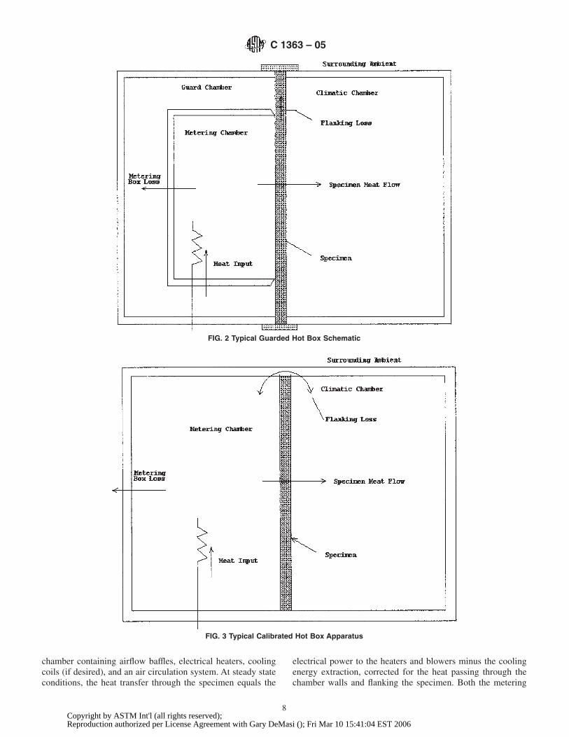
6.2.1 The basic hot box apparatus has been assembled in awide variation of sizes, orientations and designs. Two configu-rations have been historically used for a majority of thedesigns. The first is the self-masking hot box which has acontrolled “guard” chamber surrounding the metering box. Anexample of this configuration is presented in Fig. 2.
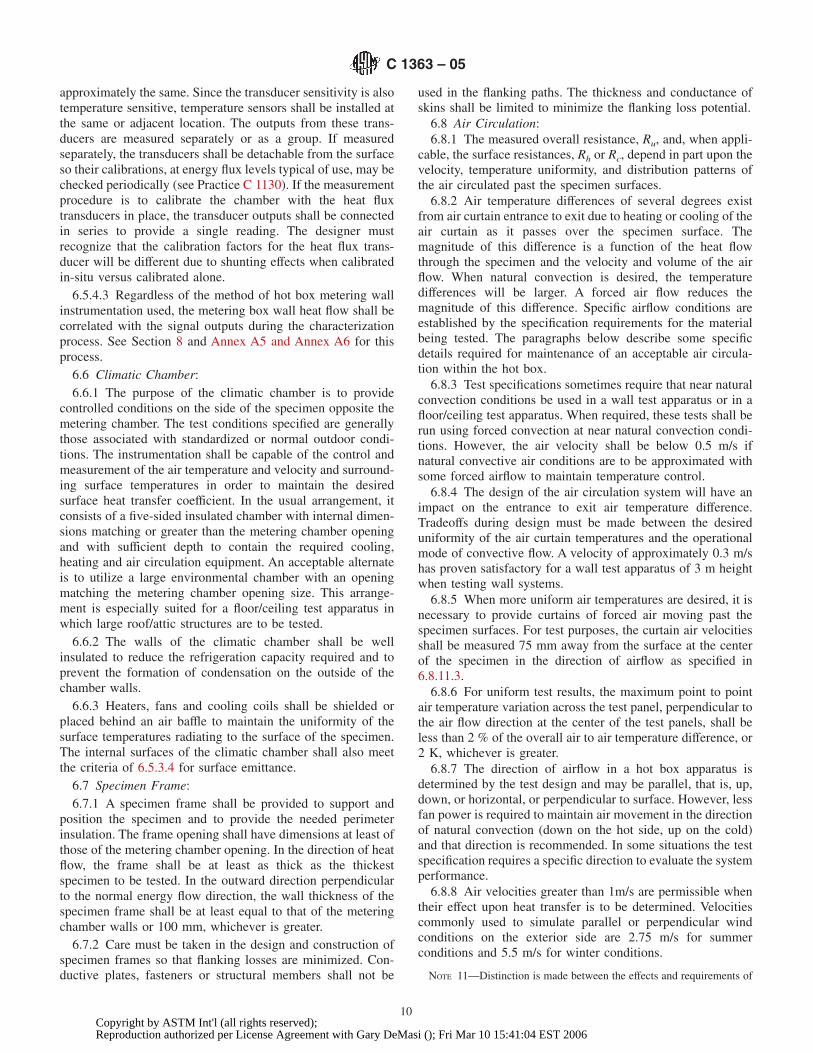
6.2.2 The second configuration is the masked hot box. Thisconfiguration can also be considered as a special case of theguarded hot box in which the surrounding ambient is used asthe guard chamber. An additional design consideration for themasked hot box design is that the metering chamber walls shallhave sufficient thermal resistance to reduce the metering boxwall loss to an acceptable level. The masked design is generallyused for testing of large specimens. Fig. 3 shows an example ofa masked apparatus for horizontal heat transfer.
NOTE 6—The two opposing chambers or boxes are identified as themetering chamber and the climatic chamber. In the usual arrangement, thetemperature of the metering chamber is greater than that of the climaticchamber and the common designations of “hot side” and “cold side”apply. In some apparatus, either direction of heat flow may apply.
6.3 Apparatus Size—The overall apparatus shall be sized tomatch the type of specimens anticipated for testing (see 7.2).For building assemblies, it shall accommodate representativesections. Generally, the maximum accuracy is obtained whenthe specimen size matches that of the metering chamber whilethe climatic chamber also matches or is larger.
NOTE 7—A large apparatus is desirable in order to minimize perimetereffects in relation to the metered area, but a large apparatus may alsoexhibit longer equilibrium times, thus, a practical compromise must bereached. Typical heights for wall hot boxes are 2.5 to 3 m with widthsequal to or exceeding the height. Floor/ceiling hot boxes up to 4 by 6 mhave been built.
6.4 Construction Materials—Materials used in the con-struction of the hot box apparatus shall have a high thermal
resistivity, low heat capacity and high air flow resistance.Polystyrene or other closed cell foam materials have been usedsince they combine both high thermal resistivity, good me-chanical properties, and ease of fabrication. One potentialproblem with some foam is that they exhibit time dependentthermal properties that would adversely affect the thermalstability of the apparatus. Problems associated with the use ofthese materials are avoided by using materials that are initiallyaged prior to assembly, or by periodic chamber verification, orby using impermeable faced foam materials with sealed edgesto greatly minimize the aging effects.
6.5 Metering Chamber:6.5.1 The minimum size of the metering box is governed by
the metering area required to obtain a representative test areafor the specimen (see 7.2) and for maintenance of reasonabletest accuracy. For example, for specimens incorporating airspaces or stud spaces, the metering area shall span an integralnumber of spaces (see 5.5). The depth of the metering box shallbe no greater than that required to accommodate the air curtain,radiation baffle and the equipment required to condition andcirculate the air. Measurement errors in testing with a hot boxapparatus are, in part, proportional to the length of theperimeter of the metering area and inverse to metering area.The relative influence of the perimeter length diminishes asmetering area is increased. Experience on testing homogeneousmaterials, has demonstrated that for the “guarded,” self-masking hot box configuration, the minimum size of themetering area is 3 times the square of the metered specimenthickness or 1 m2, whichever is larger (18). From the sameexperience base, for the “calibrated,” masked box configura-tion, a minimum metering area size is 1.5 m2. For non-homogeneous specimens, the size requirements are moresignificant.
6.5.2 The purpose of the metering chamber is to provide forthe control and measurement of air temperatures and surfacecoefficients at the face of the specimen under prescribedconditions and for the measurement of the net heat transferthrough specimen. The usual arrangement is a five-sided
FIG. 1 Typical Hot Box Apparatus Schematic—Definition of Locations and Areas
C 1363 – 05
7Copyright by ASTM Int'l (all rights reserved);Reproduction authorized per License Agreement with Gary DeMasi (); Fri Mar 10 15:41:04 EST 2006
chamber containing airflow baffles, electrical heaters, coolingcoils (if desired), and an air circulation system. At steady stateconditions, the heat transfer through the specimen equals the
electrical power to the heaters and blowers minus the coolingenergy extraction, corrected for the heat passing through thechamber walls and flanking the specimen. Both the metering
FIG. 2 Typical Guarded Hot Box Schematic
FIG. 3 Typical Calibrated Hot Box Apparatus
C 1363 – 05
8Copyright by ASTM Int'l (all rights reserved);Reproduction authorized per License Agreement with Gary DeMasi (); Fri Mar 10 15:41:04 EST 2006
box wall loss and flanking loss are determined from character-ization measurements (see Section 8 and Annex A2-AnnexA9).
6.5.3 To minimize measurement errors, several require-ments are placed upon the metering chamber walls and theadjoining ambient space:
6.5.3.1 The metering chamber heat flow corrections, whichare estimated for design purpose using the equations of AnnexA2-Annex A4, must be kept small, by making the metering boxwall area small, keeping its thermal resistance high or byminimizing the temperature difference across the wall (seeNote 8).
6.5.3.2 With proper design, the metering box wall loss arecontrolled to be as low as 1 or 2 % of the heat transfer throughthe specimen. The metering box wall loss shall never be greaterthan 10 % of the specimen heat transfer. In any case, theminimum thermal resistance of the metering chamber wallsshall be greater than 0.83 m2K/W.
NOTE 8—The 10 % limit is based upon design analysis of existing hotboxes. The choice of construction of the metering chamber can only bemade after review of the expected test conditions in which metering boxwall loss and associated uncertainties are considered in relation to theanticipated energy transfer through the metered specimen and its desiredmaximum uncertainty. The influence of the guarding temperature upon theability to maintain steady temperatures within the metering chamber mustalso be considered in choosing between highly insulated walls and atightly controlled guard space conditioning.
6.5.3.3 However large the metering box wall loss is, theuncertainty of the resulting metering box wall loss correction tothe net heat flow shall not exceed 0.5 % of the net heat flowthrough the specimen. In some designs, it has been necessaryto use a partial guard to reduce the metering chamber box wallloss.
6.5.3.4 For best results, the heat transfer through the meter-ing chamber walls shall be uniform so that a limited number ofheat flux transducers or differential thermocouples can be usedto characterize the heat flow from each representative area.This goal is best approximated by the use of a monolithic,uniform insulation uninterrupted by highly conducting struc-tural members, and by eliminating any localized hot or coldsources from the adjoining space. No highly conductivestructural members shall be within the insulation. Thermalbridges, structural cracks, insulation voids, air leaks andlocalized hot or cold spots from the conditioning equipmentinside the metering chamber walls shall be avoided.
NOTE 9—One method of constructing satisfactory chamber walls is bygluing together large blocks of an aged, uniform low thermal conductivitycellular plastic insulation such as extruded polystyrene foam. A thincovering of reinforced plastic or coated plywood is recommended toprovide durability, moisture and air infiltration control. In addition tousing a high thermal resistance, the designer must also recognize that wallheat storage capacity is also a governing factor in hot box wall design.
6.5.3.5 To ensure uniform radiant heat transfer exposure ofthe specimen, all surfaces which exchange radiation with thespecimen shall have a total hemispherical emittance greaterthan 0.8.
6.5.3.6 In applications where the metering chamber contactsthe specimen, an airtight seal between the specimen andmetering wall shall be provided. The cross section of the
contact surface of the metering chamber with the specimenshall be narrowed to the minimum width necessary to hold theseal. A maximum width of 13 mm, measured parallel to thespecimen surface plane, shall be used as a guide for design.Periodic inspection of the sealing system is recommended inorder to confirm its ability to provide a tight seal under testconditions.
6.5.4 Since one basic principle of the test method is tomeasure the heat flow through the metering box walls, ad-equate controls and temperature-monitoring capabilities areessential. Small temperature gradients through the walls occurdue to the limitations of controllers. Since the total wall area ofthe metering box is often more than twice the metering area ofthe specimen, these small temperature gradients through thewalls cause substantial heat flows totaling a significant fractionof the heat input to the metering box. For this reason, themetering box walls shall be instrumented to serve as a heatflow transducer so that heat flow through them can beminimized and measured. A correction for metering chamberwall loss shall be applied in calculating test results. The use ofone of the following methods is required for monitoringmetering box wall loss.
NOTE 10—The choice of transducer types and mounting methods usedto measure the heat flow through the metering chamber walls is guided bythe hot box design. However, they must provide adequate coverage andoutput signal to quantify the metering box wall loss during testing (see6.5.3.3).
6.5.4.1 The walls may be used as heat flow transducers byapplication of a large number of differential thermocouplesconnected between the inside and outside surfaces of themetering chamber walls. Care must be taken when determininglocations of the differential thermocouples, as temperaturegradients on the inside and outside of the metering box wallsare likely to exist and have been found to be a function ofmetering and climatic chamber air velocities and temperatures.Care must also be taken when determining the number ofdifferential thermocouples. Based upon a survey of hot boxoperators (18), a minimum of five differential thermocouplepairs per m2 of metering box wall area shall be used. Thethermocouple junctions shall be located directly opposite eachother and, preferably, located at the centers of approximatelyequal areas. Small pieces of foil, having surface emittancematching the remainder of the box walls, may be attached tothe thermocouples to facilitate the thermal contact with thewall surface. The junctions and the attached thermocouplewires shall be flush with, and in thermal contact with, thesurface of the wall for at least a 100 mm distance from thejunctions. The thermocouple pairs are connected in series toform a thermopile in which the individual voltages are summedto give a single output or read out individually in cases wheresignificant differences may occur or be expected in the localheat flow levels.
6.5.4.2 As an alternative, separate heat flux transducers areplaced on the metering chamber walls. Care must be taken inchoosing and installing the transducers to ensure that thethermal resistance of the wall and its surface emittance remainessentially unchanged. The transducers shall be initially cali-brated separately to ensure that the relative sensitivities are
C 1363 – 05
9Copyright by ASTM Int'l (all rights reserved);Reproduction authorized per License Agreement with Gary DeMasi (); Fri Mar 10 15:41:04 EST 2006
approximately the same. Since the transducer sensitivity is alsotemperature sensitive, temperature sensors shall be installed atthe same or adjacent location. The outputs from these trans-ducers are measured separately or as a group. If measuredseparately, the transducers shall be detachable from the surfaceso their calibrations, at energy flux levels typical of use, may bechecked periodically (see Practice C 1130). If the measurementprocedure is to calibrate the chamber with the heat fluxtransducers in place, the transducer outputs shall be connectedin series to provide a single reading. The designer mustrecognize that the calibration factors for the heat flux trans-ducer will be different due to shunting effects when calibratedin-situ versus calibrated alone.
6.5.4.3 Regardless of the method of hot box metering wallinstrumentation used, the metering box wall heat flow shall becorrelated with the signal outputs during the characterizationprocess. See Section 8 and Annex A5 and Annex A6 for thisprocess.
6.6 Climatic Chamber:6.6.1 The purpose of the climatic chamber is to provide
controlled conditions on the side of the specimen opposite themetering chamber. The test conditions specified are generallythose associated with standardized or normal outdoor condi-tions. The instrumentation shall be capable of the control andmeasurement of the air temperature and velocity and surround-ing surface temperatures in order to maintain the desiredsurface heat transfer coefficient. In the usual arrangement, itconsists of a five-sided insulated chamber with internal dimen-sions matching or greater than the metering chamber openingand with sufficient depth to contain the required cooling,heating and air circulation equipment. An acceptable alternateis to utilize a large environmental chamber with an openingmatching the metering chamber opening size. This arrange-ment is especially suited for a floor/ceiling test apparatus inwhich large roof/attic structures are to be tested.
6.6.2 The walls of the climatic chamber shall be wellinsulated to reduce the refrigeration capacity required and toprevent the formation of condensation on the outside of thechamber walls.
6.6.3 Heaters, fans and cooling coils shall be shielded orplaced behind an air baffle to maintain the uniformity of thesurface temperatures radiating to the surface of the specimen.The internal surfaces of the climatic chamber shall also meetthe criteria of 6.5.3.4 for surface emittance.
6.7 Specimen Frame:6.7.1 A specimen frame shall be provided to support and
position the specimen and to provide the needed perimeterinsulation. The frame opening shall have dimensions at least ofthose of the metering chamber opening. In the direction of heatflow, the frame shall be at least as thick as the thickestspecimen to be tested. In the outward direction perpendicularto the normal energy flow direction, the wall thickness of thespecimen frame shall be at least equal to that of the meteringchamber walls or 100 mm, whichever is greater.
6.7.2 Care must be taken in the design and construction ofspecimen frames so that flanking losses are minimized. Con-ductive plates, fasteners or structural members shall not be
used in the flanking paths. The thickness and conductance ofskins shall be limited to minimize the flanking loss potential.
6.8 Air Circulation:6.8.1 The measured overall resistance, Ru, and, when appli-
cable, the surface resistances, Rh or Rc, depend in part upon thevelocity, temperature uniformity, and distribution patterns ofthe air circulated past the specimen surfaces.
6.8.2 Air temperature differences of several degrees existfrom air curtain entrance to exit due to heating or cooling of theair curtain as it passes over the specimen surface. Themagnitude of this difference is a function of the heat flowthrough the specimen and the velocity and volume of the airflow. When natural convection is desired, the temperaturedifferences will be larger. A forced air flow reduces themagnitude of this difference. Specific airflow conditions areestablished by the specification requirements for the materialbeing tested. The paragraphs below describe some specificdetails required for maintenance of an acceptable air circula-tion within the hot box.
6.8.3 Test specifications sometimes require that near naturalconvection conditions be used in a wall test apparatus or in afloor/ceiling test apparatus. When required, these tests shall berun using forced convection at near natural convection condi-tions. However, the air velocity shall be below 0.5 m/s ifnatural convective air conditions are to be approximated withsome forced airflow to maintain temperature control.
6.8.4 The design of the air circulation system will have animpact on the entrance to exit air temperature difference.Tradeoffs during design must be made between the desireduniformity of the air curtain temperatures and the operationalmode of convective flow. A velocity of approximately 0.3 m/shas proven satisfactory for a wall test apparatus of 3 m heightwhen testing wall systems.
6.8.5 When more uniform air temperatures are desired, it isnecessary to provide curtains of forced air moving past thespecimen surfaces. For test purposes, the curtain air velocitiesshall be measured 75 mm away from the surface at the centerof the specimen in the direction of airflow as specified in6.8.11.3.
6.8.6 For uniform test results, the maximum point to pointair temperature variation across the test panel, perpendicular tothe air flow direction at the center of the test panels, shall beless than 2 % of the overall air to air temperature difference, or2 K, whichever is greater.
6.8.7 The direction of airflow in a hot box apparatus isdetermined by the test design and may be parallel, that is, up,down, or horizontal, or perpendicular to surface. However, lessfan power is required to maintain air movement in the directionof natural convection (down on the hot side, up on the cold)and that direction is recommended. In some situations the testspecification requires a specific direction to evaluate the systemperformance.
6.8.8 Air velocities greater than 1m/s are permissible whentheir effect upon heat transfer is to be determined. Velocitiescommonly used to simulate parallel or perpendicular windconditions on the exterior side are 2.75 m/s for summerconditions and 5.5 m/s for winter conditions.
NOTE 11—Distinction is made between the effects and requirements of
C 1363 – 05
10Copyright by ASTM Int'l (all rights reserved);Reproduction authorized per License Agreement with Gary DeMasi (); Fri Mar 10 15:41:04 EST 2006
air velocity parallel to the specimen surface and those for velocityperpendicular to it. Parallel velocities simulate the effect of the crosswinds, and may be achieved by moving a small amount of air confined ina narrow baffle space and therefore require relatively little blower power.Perpendicular velocities, simulating direct wind impingement, requiremoving larger amounts of air with corresponding larger power require-ments. The baffles in the second case must be placed further from thespecimen surface and should have a porous section (a set of screens or ahoneycomb air straightener) that directs the air stream to the specimensurface. Fig. 4 shows an example of climatic chamber arrangement forperpendicular flow.
6.8.9 Air Baffles—For parallel flow, a baffle, parallel to thespecimen surface, shall be used to confine the air to a uniformchannel, thus aiding in maintaining an air curtain with uniformvelocities.
6.8.9.1 The baffle thermal resistance shall be adequate toshield the specimen surface from radiative heat exchange withany energy sources located behind it. A baffle thermal resis-tance of 1 (m2 K /W) is recommended for this purpose. Otherbaffle designs that maintain temperature uniformity of thebaffle surface seen by the test specimen are acceptable.
6.8.9.2 An adjustable baffle-to-specimen spacing is onemeans of adjusting the airflow velocity. For purpose ofmaintaining a well-mixed and characterized air curtain, aspacing of 140 to 200 mm is recommended.
6.8.9.3 A baffle also serves as a radiation exchange surfacewith a uniform temperature only slightly different than that ofthe air curtain. The baffle surface facing the specimen shallhave an emittance greater than 0.8.
6.8.10 Air Velocity Uniformity—Uniform air flow profileacross the specimen width, perpendicular to the air flowdirection, is achieved by use of multiple fans or blowers or byuse of an inlet distribution header across one edge of the baffle
and an outlet slot across the opposite. The inlet header shallincorporate adjustable slots or louvers to aid in obtaininguniform distribution.
6.8.10.1 After construction of an air circulation system, theair velocity profile shall be measured across the area perpen-dicular to the direction of airflow in the proximity of thespecimen. The test shall be conducted with a flat, homogeneouspanel in place so that the surface of the test panel has minimumeffect on the velocity profile. The air velocity profile shall bedefined as uniform if all measurements from the profile scanare within 10 % of the mean of all measurements. For parallelair curtains, the air flow measurements shall be made at 0.3 mintervals across the specimen face, perpendicular to the air flowdirection, at the centerline of the metering chamber. For airflow perpendicular to the specimen face, the air flow measure-ments shall be made in the radial direction at a density of oneper every 30 degrees around the outlet of the diffuser at adistance from the center of the metering area equal to the outletdiameter of the air supply diffuser. If the profile is not uniform,additional adjustments shall be made to the inlet header slot orlouvers or in the placement of fans or blowers to achieve an aircurtain with uniform velocity across the face of the specimen.The velocity profiles shall be verified, whenever modificationor repairs of the distribution system are made that might causea change in flow patterns. Also, the profiles shall be verifiedduring characterization checks.
NOTE 12—Linear air diffusers designed for ceiling air distributionsystems have been found satisfactory to use as distribution headers. Forlarge floor/ceiling testers it may be necessary to use more than one set offans or inlet and outlet headers creating opposing zones to obtain therequired temperature uniformity. Tangential fans have also been found toprovide uniform temperatures.
FIG. 4 Hot Box Arrangement for Perpendicular Air Flow
C 1363 – 05
11Copyright by ASTM Int'l (all rights reserved);Reproduction authorized per License Agreement with Gary DeMasi (); Fri Mar 10 15:41:04 EST 2006
6.8.11 Air Velocity Measurement—The apparatus designshall provide a means for determining mean air velocity pastboth the hot and cold faces of the specimen during each test.Acceptable methods are as follows:
6.8.11.1 One method is to measure the volumetric airflow inthe duct to the inlet distribution header by using a calibratedorifice or other flow-measuring device. The average bafflespace velocity is then calculated from the volume flow and thesize of the space between the specimen and the parallel baffle.The baffle must be well sealed for this technique to work.
6.8.11.2 Another method is to calculate the velocity from anenergy balance. The rate of loss, or gain, of heat by the air asit moves through the baffle space, as indicated by its tempera-ture change, will match the rate of heat transfer through themetering chamber opening, average values of which can bedetermined from the test data.
6.8.11.3 The best method is to locate velocity sensorsdirectly in the air curtain. For test purpose, wind velocity shallbe measured at a fixed location that represents the average freestream condition. For both perpendicular and parallel flowpatterns, this location shall be a distance out in the air streamsuch that the wind speed sensor is not in the test specimensurface boundary layers or wakes. A distance of 75 to 150 mmout from the test specimen surface at the center point istypically used. On the room side, where low circulationvelocities are generally used, a properly located sensor is alsorequired. The operator’s experience and knowledge of the airdistribution system obtained in the profiles from 6.8.10 shall beused to determine the optimum sensor location.
6.9 Air Temperature Control:6.9.1 The temperature of the air entering the air curtains
shall be within 6 1 K of the setpoint temperature across itswidth and, for steady-state tests, shall not change during themeasurement period.
6.9.2 One method of providing controlled, heated air is toinstall open wire, low thermal mass electrical heaters in aninsulated, low emittance section of the blower duct or otherpart of the air circulation system and to control these heatersusing a sensor located at the inlet to the air curtain.
NOTE 13—Another method of heater control is to use several individualheaters that are switched on to provide fixed levels of energy. Fine-tuningis provided by an additional heater modulated by a controller. Anothersatisfactory method is to use a controller that varies the power to all theheaters.
6.9.3 Methods for cooling the climatic chamber include theinstallation of a refrigeration system evaporator inside thechamber, ducting in chilled air from an external source orinjecting liquid nitrogen. Usually the evaporator or externalchilled air is controlled at a constant temperature a few degrees(typically < 5°C) below the desired setpoint. Then, a reheat andcontrol system, similar to that for obtaining heated air (see6.9.2) is used to achieve fine control of the temperature at theinlet to the specimen air curtain. When liquid nitrogen is useda valve regulating its flow is pulsed or modulated to obtain finetemperature control.
NOTE 14—One proven configuration for a climatic chamber utilizestwo air circuits created by suitable baffles. The evaporator fan creates onecirculation path that includes a mixing chamber from which air is
circulated by a separate blower to the specimen air curtain and returned.An air reheat and control system provides fine control of air temperatureat the distribution header inlet. Other proven configurations utilize only asingle air circuit containing both cooling and reheat elements. Undercertain conditions, a desiccant may be needed to remove moisture fromthe air stream.
6.9.4 Metering chamber blowers shall be small and efficientsince, without cooling, they determine the least possible netenergy input to the metering chamber. If large fans or blowersare necessary, then compensatory cooling with inherent loss inaccuracy shall be used. Some heat is removed by locating theblower motor outside of the metering chamber and accuratelymeasuring the heat equivalent of the shaft power. Precautionsshall be taken to prevent air leakage around the shaft.
6.9.5 When cooling of the metering chamber is required, itmust be done in a manner in which the amount of heatextracted can be measured accurately. One method is tocirculate a chilled liquid through a heat exchanger located inthe metering chamber air circuit. The rate of heat extraction iscontrolled by the inlet to chamber air temperature difference,the airflow rate, the liquid properties, and the heat exchangerefficiency. The amount of cooling used shall be limited to thatnecessary to overcome any excess blower or other heatingloads since test accuracy will be lost if excessive heating mustbe used to compensate for large cooling. For example, assumethat the heater input was 400 Btu/h out of an overall heatercapacity of 2000 Btu/h and is known to within 1 % of capacityor 6 20 Btu/h. Also assume a concurrent cooling load of 320Btu/h out of an overall cooling capacity of 1600 Btu/h whichis known to within 1 % of capacity or 6 16 Btu/h. Since theseloads oppose each other, the net load is 80 Btu/h but theuncertainty of the net could be as large as 6 36 Btu/h or 45 %of the net load. For this reason, care must be observed inobtaining the correct test setup.
6.9.6 Special Considerations, Humidity Control—Moisturemigration, condensation, and freezing within the specimen canalso cause variations in heat flow. To avoid this, the warm siderelative humidity shall be kept below 15 %.
6.10 Temperature Measurement:6.10.1 When surface temperatures are required, specimen
surface temperature sensors shall typically be located oppositeeach other on the two faces of the specimen. However, whenplacement opposite each other is not possible, the sensors shallbe placed to represent the correct area weighting for eachsurface. These sensors shall be chosen and applied to thesurface in a manner such that the indicated temperature iswithin 6 0.2 K of the temperature that would exist if the sensorhad not been applied. This requirement is met by thermo-couples if: (1) the wire is no larger in diameter than 0.25 mm(No. 30 AWG.); (2) the wire meets, or is calibrated to, thespecial limits of error as specified in the Tables E 230; (3) thejunctions, not larger than two times the wire diameter, aretwisted and welded or soldered; (4) 100 mm of adjoining wireare taped, cemented or otherwise held in thermal contact withthe surface using materials of emittance close (6 0.05) to thatof the surface; and (5) they are electrically insulated, orotherwise protected, so that the electrical junction is at thelocation of the thermocouple bead. Application of alternate
C 1363 – 05
12Copyright by ASTM Int'l (all rights reserved);Reproduction authorized per License Agreement with Gary DeMasi (); Fri Mar 10 15:41:04 EST 2006
temperature sensor systems may be used if comparativemeasurements or calculations show that the basic requirementsare met.
NOTE 15—Metal foil tape, which has been painted to make theemittance greater than to 0.80, is an effective means to attach thermo-couple sensors to most high emittance test specimens.
6.10.2 If the specimen construction, and therefore its ther-mal resistance, is uniform over its entire area, then a minimumnumber of sensors, spaced uniformly and symmetrically overthe surface, are sufficient. The required minimum number ofsensors per side shall be at least two per square meter ofmetering area but not less than nine (24).
6.10.2.1 If each element of the specimen construction isrelatively uniform in thermal resistance and is repeated severaltimes over the entire surface, the number of sensors specified in6.10.2 may still be sufficient. In this case, the sensors shall belocated to obtain the average surface temperature over eachtype of construction element and, for each type of element,shall be distributed approximately uniformly and symmetri-cally over the specimen area. The average surface temperatureof the specimen shall be calculated by area weighting of theaverages for the different types of construction elements.
6.10.2.2 If the surface temperatures are expected to be, orfound to be, greatly non-uniform, additional sensors shall berequired. Often a great number, such as three or more times thenormal amount as determined by trial and error, is required toadequately sample the different temperature areas so that areliable area weighted mean surface temperature may beobtained. Some research has been published on the subject oftesting highly conductive member that might be used asguidance for this determination. For example, see the work onsteel framed buildings (29).
6.10.2.3 If an accurate determination of the average surfacetemperatures cannot be obtained, the hot box apparatus canaccurately measure only the thermal transmittance, U, or theoverall thermal resistance, Ru. The average panel resistance, R,of the specimen can be estimated by subtracting off thepreviously determined surface film thermal resistances estab-lished using a transfer standard of equal thermal resistance,size, surface configuration and roughness. Note that the geom-etry, average temperatures, and energy exchange conditionsmust be similar for the calibration transfer standard (CTS) andtest panel for this technique to have reasonable accuracy. (SeeTest Method C 1199 for discussion on CTS design.)
NOTE 16—Tests on specimens containing thermal bridges requirespecial care because of the possible great differences in thermal resistanceand temperatures between the thermal bridge areas and those of surround-ing insulated structures. Added complications arise when tests are run athigher air velocities since temperatures and energy transfer can dependsignificantly upon bridge geometry relative to the overall sample as wellas the velocity and direction of air movement. If test results are to becomparable for competing systems, they must be run under similarconditions. This method does not attempt to standardize such conditions.
6.10.3 The temperature of the air on each side of thespecimen shall be measured by thermocouples, temperaturesensitive resistance wires, or similar temperature sensors.
6.10.3.1 The minimum number and locations of sensorsused to measure air temperatures shall be that specified for
surface temperature sensors in 6.10.2. These sensors must beradiation shielded or otherwise protected to provide an accurateindication of the temperature of the air curtain. Sensors shall besmall to ensure fast response to changing temperatures. Resis-tance wires, if used, shall be distributed uniformly in the aircurtain.
NOTE 17—One suitable radiation shield is made by using 12 mmdiameter, 75 mm long pieces of thin walled plastic tubing covered on theoutside with aluminum foil tape. The air thermocouple is placed at thecenter of the tube to measure the air stream temperature and yet beshielded from radiation sources.
6.10.3.2 The best location for temperature sensors dependsupon the type of air curtain convection (natural or forced). Innatural convection situations, it is usually possible to identifythe temperature of still air outside the boundary layer. Conse-quently, when natural convection is established, air tempera-ture sensors shall be located in a plane parallel to the specimensurface and spaced far enough away from it that they areunaffected by temperature gradients of the boundary layer. Forminimum velocities required to attain temperature uniformities(see 6.8 and Note 12), the minimum spacing from the specimensurface is 75 mm. At velocities greater than 1 m/s, the requiredminimum spacing is greater. The boundary layer thicknessincreases sharply at the transition from laminar to turbulentflow. With fully developed turbulent flow, the boundary layeroccupies the full space between the specimen and the baffle.When forced convection is established and the flow is fullydeveloped, the sensors shall be located at a distance from thespecimen surface corresponding to 2⁄3 up to 3⁄4 of the specimen-to-baffle distance. This is to detect a temperature approachingthe airflow bulk temperature.
6.10.3.3 Thermocouple sensors used for measurement of airtemperatures shall meet the requirements of Items (1), (2), (3),and (5) in 6.10.1. Other sensors are acceptable if they havesimilar time response and are calibrated so that the measure-ments are accurate within 6 0.5 K.
6.10.4 The surface temperature of the baffles in the meteringand climatic chambers, where required, shall be measured byplacing sensors on all surfaces seen by the specimen. Aminimum area density of three sensors per square meter ofbaffle area, but not less than one sensor per baffle surface, isrequired. These data (1) can be used to determine any differ-ence between the baffle surface and air curtain temperatures;(2) permits corrections to be made to the radiation componentof the surface film conductance due to differences in thesetemperatures; and (3) is a necessary component of the dataanalysis for specimens such as windows which have a highthermal conductance. (See the discussion on the environmentaltemperature determination in Annex A9.)
6.11 Specimen Pressure Difference:6.11.1 For some tests, it is necessary to establish and
measure the air pressure differential between the faces of thetest specimen. This is especially important for window andother samples where the airflow resistance between the speci-men surfaces is low. The specimen pressure difference isdefined as the difference in the local static pressure, on eitherside of the specimen, measured at a location at the geographic
C 1363 – 05
13Copyright by ASTM Int'l (all rights reserved);Reproduction authorized per License Agreement with Gary DeMasi (); Fri Mar 10 15:41:04 EST 2006
center of the metered area, at a distance 75 mm from thesurfaces of the sample.
6.12 Instruments:6.12.1 All signal conditioning and data logging instruments
shall be located outside of the apparatus. All instruments shallbe calibrated to the specified accuracy, traceable to a nationalstandards laboratory, and shall meet the following additionalrequirements:
6.12.1.1 All instrumentation shall have adequate sensorresponse so that the scanning speed does not adversely effectthe measurement results.
6.12.1.2 Temperatures shall be readable to 6 0.05 K and beaccurate within 6 0.5 K.
6.12.1.3 Heat flux transducer outputs shall be measured tothe precision required to limit the error in estimation of themetering box wall loss to less than 6 0.5 % of the specimenenergy transfer. This requires a heat flux transducer calibrationaccuracy of 5 percent or better.
6.12.1.4 Many methods of air velocity measurement arepossible depending on the specific box design and test condi-tions. However, an accuracy of 6 5 % of the reading isrequired. A sensor whose signal can be processed by automaticdata acquisition equipment is recommended.
6.12.1.5 Pressure difference measurements shall be accurateto within 6 5 % of reading or 6 1 Pa, whichever is greater.
6.12.1.6 Total average power (or integrated energy over aspecified time period) to the metering box shall be accurate towithin 6 0.5 % of reading under conditions of use. Powermeasuring instruments shall be compatible with the powersupplied whether ac, dc, on off, proportioning, etc. Voltagestabilized power supplies are strongly recommended. Meteredcooling instruments shall be calibrated together as a system tosimilar accuracy.
6.12.1.7 Temperature controllers for steady-state tests shallbe capable of controlling temperatures constant to within 6
0.25 K (see 6.9).
7. Sampling and Test Specimens
7.1 Building elements shall be representative of typical fieldassemblies. As such, the metered specimen is usually a portionof a building assembly that has been selected for test due to theexpectation that it will exhibit the same thermal behavior as thelarger building element that it represents. Tests on apparatusrequiring smaller than representative specimens shall beavoided. The construction details of the building elements to beinvestigated may be modified but only if necessary for testpurposes. It must be recognized that modifications to theconstruction result in conditions that do not represent true fieldconditions. Conduction and convection paths that have consid-erable effect on the performance of the building elements mustbe left intact. During specimen design the following shall beconsidered.
NOTE 18—Reduced scale elements shall not be tested with the intent ofextrapolating results to larger elements unless detailed modeling analysisclearly shows the validity of the extrapolations.
7.2 Building Element Sizing:
7.2.1 The building element shall be sized for the apparatus.Normally the outside dimensions of the building element shallmatch the dimensions of the metering chamber opening.
7.2.2 Wherever possible, the percent framing and insulatedcavity space dimensions of the building element shall be thesame as the building assembly it represents.
7.2.3 For elements such as an opaque envelope section, thebuilding element is defined by an integral number of structuralsections. For example, a residential wall section constructed of0.41 m on center framing by 2.44 m wall height, would have aspecimen size of at least 1.22 m wide by 2.44 m high. Metalbuilding sections shall have a specimen width equal to theframing dimension, often 1.52 m.
7.2.4 If smaller elements must be tested, a surround panelshall be used to fill out the required size. The surround panelaperture for test purpose shall be sufficiently small relative tothe metering area such that the minimum distance between themetering area boundary and the aperture boundary is greater orequal to 100 mm (see Annex A5).
7.2.5 For building elements having limited dimensions suchas windows, doors, etc., the test specimen shall be the completecomponent plus the necessary surround panel.
7.2.6 For a building element having thermal behavior that ismostly independent of its horizontal and vertical dimensions,the test specimen size is at least that necessary to obtain anaverage performance for the material system. For example,insulated systems such as foam sandwich structure panels, arerelatively uniform in the cross directions but may be non-uniform through the thickness. The test specimen for this typeof material shall be large enough to obtain an average valuewhich accounts not only for manufacturing variability but alsoincludes the effect of joint details between adjacent panelswhen tested as a system.
7.2.7 For the characterization of homogeneous or nearlyhomogeneous materials that are self-supporting, the test speci-men shall consist of a single layer of material. However,specimen assembly precautions such as sealing the surfacesshall be observed.
7.2.8 Three-dimensional structures may be tested if theapparatus size permits.
7.3 Sensors—The temperature sensors for the measurementof surface temperatures shall be installed as directed in 6.10.Additional sensors may be installed throughout the interior ofthe specimen for special investigations of local temperaturevariations.
7.4 Mounting—The building element shall be located in thesame position in test frames as the specimen was duringcharacterization tests so that flanking geometry is duplicated.
7.5 Sealing—The building element shall be gasketed,caulked, taped, or otherwise sealed in place to prevent airmovement around its perimeter. The procedures and materialfor sealing shall be chosen to minimize flanking loss. If thebuilding element is suspected of being porous so that asignificant energy transfer results from air infiltration throughthe building element, then tests shall be run before and aftersealing both faces. If the overall resistance changes signifi-cantly, then the building element does not possess uniqueproperties independent of the imposed conditions. Results from
C 1363 – 05
14Copyright by ASTM Int'l (all rights reserved);Reproduction authorized per License Agreement with Gary DeMasi (); Fri Mar 10 15:41:04 EST 2006
all tests must be reported. Thin, air impervious sheets of paperor plastic, may be glued on to seal surfaces without signifi-cantly affecting thermal conduction. Some building elementsare sealed with suitable paint. In all cases, the surface emit-tance of the sealed building element shall be within 6 0.1 ofthe emittance of the original unsealed building element.
7.6 Perimeter Insulation—Insulation shall be used at thebuilding element perimeter. This insulation normally is incor-porated into the re-usable specimen frame but may be newlyinstalled for each building element. If newly installed, it shallbe fully characterized in order to account for the surroundpanel flanking loss.
7.7 Internal Air Barriers—Testing of a building element,with uninterrupted internal air cavities that extend beyond theboundaries of the metering section is not permitted. Tocharacterize building elements having uninterrupted air cavi-ties that are larger than the metering chamber, it is necessary toalter the element by placing an internal convection barrier ineach cavity where it crosses the boundary of the meteringchamber. These barriers are required to prevent undesired airexchange between the metering and guard areas of the speci-men. For example, such barriers are required for vertical wallcavities extending above or below the metered area when thecavity is insulated with reflective insulation having no internalair barriers. Any modifications to the building element shall bereported.
7.8 High Lateral Conductance Building Elements—For allbuilding elements, it is necessary to maintain a near zero lateralenergy flow between any guard and the metering areas of thespecimen. This can be achieved by maintaining a near zerotemperature difference on the building element surface be-tween the metering and guard areas. However, in buildingelements incorporating an element of high lateral conductance,such as a metal sheet, it is necessary to separate the highlyconductive element with a thermal break. One form of thermalbreak is a narrow gap caused by a saw cut at the meteringchamber boundary.
7.9 When testing high thermal resistance specimens that aresmaller than the metering area using a surround panel, the heatloss through the surround panel may approach or exceed theheat loss through the specimen. In this case, the operator shalldetermine the uncertainty of the test result and include thatuncertainty value in the report.
8. Apparatus Characterization
8.1 All fundamental measurement devices used in the hotbox control and data acquisition systems shall be individuallymaintained and calibrated to meet their design accuracyspecifications. In general, this requires that each device betraceable to standards obtained from a national standardslaboratory. Records of this calibration and periodic calibrationverification checks shall be maintained in the laboratory files.Frequency of validation checks will be dependent on thepurpose, style and stability of the equipment used.
8.2 Hot box apparatus characterization is necessary sincethe measured net heat input to the metering chamber includesnot only the heat transfer through the specimen, but alsometering box wall loss, flanking loss, and other such heat flowsas through gaskets, penetrations for wires or pipes, mechanical
fasteners, or other less obvious heat flow paths. Thus, the netmetered specimen heat transfer shall be determined from themeasured heat input by applying a correction for these flows.This correction, which is determined by characterization pro-cedures, is different for each set of operating conditions and formetered specimens of different thickness or thermal resistance.The accuracy of the test results depends upon the accuracy ofthis correction. In a properly designed apparatus, however, theflows are a relatively small fraction of the metered specimenheat transfer under steady-state conditions and any error in thecorrection is reduced by a similar fraction in its effect upon thefinal result.
NOTE 19—A discussion of the characterization for the metering cham-ber walls is presented in Annex A3. A discussion of Flanking Losscharacterization for one apparatus is given by Lavine et al. (12) and inAnnex A7. The overall test matrix for the characterization is discussed inAnnex A6. Examples of typical characterization matrices are presented inthat section.
8.3 In principle, if all details of the hot box construction andall material thermal properties are known, it is possible tocalculate all extraneous flows for a particular set of testconditions and then apply this calculated correction to mea-sured data for unknown test specimens. However, because ofthe uncertainties involved, a wholly calculational characteriza-tion procedure, without experimental verification at the testconditions, shall not be used for this method. In general, suchcalculations are practical only with monolithic walls made ofhomogeneous material. If calculated corrections, after initialexperimental verification, are used, then the chamber wall heatflow meter or thermopile outputs are used as a check to indicateany future changes in wall material properties. Calculations areuseful in estimating the magnitude of the major heat flows sothat characterization procedures may be better directed. Indeed,the most practical characterization technique uses correctionsdetermined experimentally for a limited set of conditions, butmodified on the basis of calculated estimates for use undersomewhat different conditions of test. In general, the charac-terization procedure of 8.5, using a correction developedstatistically from tests on standard reference materials shall beused. The choice of the characterization procedure details shallbe made only after a review of the expected accuracy judgedagainst the accuracy needed and against the practicability ofthe various procedures available.
8.4 Characterization Specimens—The accuracy of the char-acterization specimen measurements will depend upon thevariability of the material, the means of sampling and theaccuracy of the apparatus used to measure it. The accuracyrequired will depend upon the contemplated use. For highestaccuracy, a characterization specimen having a known thermalresistance over the range of test mean temperatures is required.Such specimens shall be impervious to air and thermal radia-tion transfer, shall be free of internal air spaces that wouldaffect the thermal resistance or allow internal convection, andshall be stable over the time period of use. Additionally, suchspecimens shall possess a thermal resistance that is essentiallyconstant over all areas of the specimen so that propertiesdetermined on smaller areas will be representative of those ofthe whole area. Any joints necessary in large specimens shall
C 1363 – 05
15Copyright by ASTM Int'l (all rights reserved);Reproduction authorized per License Agreement with Gary DeMasi (); Fri Mar 10 15:41:04 EST 2006
be designed to minimize deviations in thermal resistance (asverified by small scale tests of specimens with and withoutjoints). Characterization specimens shall be self-supportingand capable of being transported, repeatedly mounted andtested, and stored for future use without change in thermalresistance. These properties are also required for specimensused in inter-laboratory comparison tests (round robins). Thethermal resistance of characterization specimens shall bedetermined by measurements in proven apparatus conformingto Test Methods C 177 or C 518 or another hot box that hasbeen verified or calibrated by specimens traceable to a nationalstandards laboratory. Generally, the hot box characterizationspecimen will be larger than the apparatus used in thesemeasurements; thus, it will be necessary to measure smallerrepresentative pieces. Such pieces are cut from the character-ization specimen if they can be replaced without change in theaverage thermal properties, or they are selected from compan-ion pieces of the same lot of material used to fabricate thespecimen.
NOTE 20—Suitable characterization specimens have been constructedfrom molded glass fiberboard of approximately 100 to 125 kg/m3 densityor aged cellular polystyrene (XPS) board. During the tests both surfaces ofthe characterization panel shall be faced with an air impervious skinshaving an emittance greater than 0.8.
8.5 Metering Box Wall Characterization—An Overview—Since significant heat flows may exist which are not directlyrelated to heat flow through the chamber walls and thereforenot related to the voltage output of the wall energy flow metersor thermopiles, a full experimental characterization is neces-sary. This characterization involves running a series of testsover the expected operating temperature range using a charac-terization specimen of known thermal resistance (see 8.3). Foreach test, determination is made of the difference between themeasured heat input to the metering chamber and the heattransfer through the characterization specimen, calculated fromthe measured temperature drop across it and its known resis-tance. It is impractical to run a sufficient number of tests tocover all possible sets of operating conditions. Since some ofthe extraneous heat flows included in the measurement are notmetered separately (and indeed may be unknown), it isnecessary to utilize statistical techniques to develop a usablecorrelation between the corrections and the test conditions. Auseful procedure is to relate the correction to the test variablesusing a multiple linear regression. The significant test vari-ables, or combinations of test variables, can often be deter-mined from physical models. Those variables may include themean temperature of the specimen and of the metering cham-ber walls, the temperature difference across the specimen, andacross the metering chamber walls (related to the output of thechamber heat meters or thermopiles) and the temperaturedifference across any partial guards used. The regressioncorrelation coefficients can be used to judge the statisticalquality of the regression relation and the choice of variables.For greatest accuracy, it is necessary to run characterizationspecimens covering the expected range of specimen thicknessand thermal resistance and to include these variables in theregression analysis.
NOTE 21—Examples of characterization procedures are given by
Rucker and Mumaw (9), by Lavine, et al (12) and in Annex A3 throughAnnex A7.
8.6 In addition to the initial characterization sequence, it isnecessary to repeat selected measurements at times dictated byeither the known aging characteristics of the materials used inthe metering chamber wall construction or, more often, asrequired by contractual or certification regulations. A singletest may often be sufficient to verify that properties have notchanged. The maximum time between verification of charac-terization shall be one year.
8.7 It is recommended that the performance of an apparatusbe periodically confirmed by successful measurements onspecimens traceable to a national standards laboratory, previ-ously measured building specimens of known thermal perfor-mance or as part of a laboratory accreditation program.Participation in inter-laboratory round robin programs andcomparisons with another proven hot box apparatus are othermethods to demonstrate continued satisfactory operation.
9. Conditioning
9.1 Conditioning requirements specified by code or con-struction specifications shall govern for the test, where avail-able. Normally pre-test conditioning shall be in ambient air, fora period long enough to come to practical equilibrium. If therequester does not provide specific conditioning instructions,use Practice C 870 as a guide for conditioning. The recom-mended condition is in air at 24 6 2°C with 50 6 5 % relativehumidity. To avoid abnormally long conditioning periods,building materials may be preconditioned at laboratory condi-tions prior to specimen assembly. Other conditioning may beused as, for example, long term exposure to cold dry (outsidewinter) air on one side and warm, moderately humid (inside)air on the other to investigate the effects of moisture or icebuild up.
10. Test Procedure
10.1 Detailed written operating procedures for each testapparatus shall be developed and shall be available to ensurethat the tests are conducted in accordance with the require-ments of this test method.
10.2 Test Conditions:10.2.1 Whenever available, product or system specifications
or applicable code requirements for all test conditions shall beused.
10.2.2 Specimen orientation and direction of heat transfer,hot-side and cold-side air temperature and velocities anddifferential pressure, when not specified, shall be chosen tomeet requirements of the building element investigation, usu-ally to match in-use conditions.
10.2.3 When not otherwise directed, the air velocities shallbe the minimum required to achieve the desired temperatureuniformity under the requirements of 6.8.4, be in the directionof natural convection, and the metered specimen pressuredifferential shall be essentially zero.
10.2.4 Whenever the temperature conditions are not other-wise specified, Practice C 1058 shall be used as a guide forselecting the appropriate test temperature conditions.
C 1363 – 05
16Copyright by ASTM Int'l (all rights reserved);Reproduction authorized per License Agreement with Gary DeMasi (); Fri Mar 10 15:41:04 EST 2006
10.2.5 When testing fenestration products, Test MethodC 1199 and Practice E 1423 shall be used as a guide forselecting the appropriate test environmental conditions.
10.3 Construct the building element in the specimen frameopening as specified in Section 7 including installation of allrequired sensors.
10.3.1 Some metered specimens require adequate time tocome to thermal and moisture equilibrium after assembly.These shall be conditioned at laboratory conditions as long asnecessary to establish equilibrium, that is, constant weight.One example would be concrete walls or wet applied insula-tions in a frame wall.
10.4 Place the test frame, with the metered specimeninstalled, in the opening between the climatic and meteringchambers.
10.5 Make all necessary electrical connections and checkout the data acquisition system for measurement continuity.
10.6 Complete sealing of the hot box system in preparationfor the test. Check the installed metered specimen for airleakage, if possible (see 7.5 and Note 24).
10.7 Start conditioning systems and set temperature controlsto the appropriate temperature set points to yield the desiredtemperature conditions.
10.8 Begin data acquisition scanning of the test apparatusand continue the operation until the steady conditions de-scribed in 10.10 are obtained.
10.9 As specified in 6.9.6, avoid test conditions that causecondensation on the metered specimen surfaces during the test.This requirement becomes more difficult to satisfy whentesting building elements with highly conductive componentssuch as steel stud walls or single glazed windows. For example,the National Fenestration Rating Council (NFRC) window testoperators have observed that the relative humidity in themetering chamber must be below 15 % to prevent the forma-tion of frost on highly conductive window frames tested at−18°C cold side and 21°C hot side air temperatures.
10.10 Stabilization and Test Times:10.10.1 Thermal Steady-State—For purpose of this test
procedure the definition of thermal steady-state is identical tothat described as steady-state (thermal) in Terminology C 168.
10.10.2 The required time to reach stability for a steady-state test depends upon the properties of both the meteredspecimen and of the apparatus as well as upon the initial andfinal conditions of the test. Since these factors can vary overwide ranges, a single specification of required stabilizationtime and the test period for data acquisition couldn’t beprovided. A combined apparatus and metered specimen timeconstant, teff, calculated from dimensions and estimated physi-cal properties, can be helpful in estimating stabilization times.
NOTE 22—The thermal time constant, teff, of the system is the timerequired to come to within 1/e (37 %) of the final value of the thermalresistance after a step temperature disturbance of the system. This time isstrongly dependent on the mode of operation. Two modes of operationhave been used for a hot box operation. They are (1) constant power to themetering chamber and (2) constant temperature control of the meteringchamber. The constant temperature operation mode is usually used sinceit has a considerably shorter time constant because it is not significantlydependent on the thermal mass of the metering chamber. For the constantpower mode, the thermal time constant is the time required to come within
37 % of the final temperatures. The thermal time constant of the constanttemperature mode is the time required to come to within 37 % of the finalpower level. The thermal time constant of a simple system can beestimated from knowledge of the thermal diffusivities of the componentsof the system, but it is more readily determined experimentally forcomplex systems.
10.10.3 Annex A10 contains a suggested procedure forestimating the thermal time constant of a test system.
10.10.4 Normally, the thermal capacity of either the appa-ratus or metered specimen will be the controlling factor.However, since this test method is applicable to low conduc-tance specimens, the time to reach steady state is on the orderof hours. Even with this information, it may be difficult tojudge whether stability has been reached and the operator shallrely upon previous test experience and observations or uponcomputer assisted statistical prediction of trends. The follow-ing guidelines are recommended but shall not be regarded assufficient criteria in all cases.
10.11 Test Data Acquisition and Completion:10.11.1 Data Acquisition—After the final test temperature
conditions are reached, five successive repeated data acquisi-tion sets shall be obtained. These sets shall be obtained at a dataset time interval equal to the approximate time constant, teff, ofthe measured system but not less than 30 minutes. In somelaboratories, an individual data set is developed from theaverage value for each variable obtained from multiple, evenlyspaced, data scans during the permitted time interval.
10.11.2 Test Completion Criteria—This combination of fivedata acquisition runs shall constitute a valid test if the datumobtained for each measured variable differs from its mean byno more than the uncertainty of that variable. If the dataobtained during this period is changing monotonically withtime, the test shall also be considered incomplete and furtherrepeated runs shall be conducted until the steady drift is nolonger observed. Such a drift, even at low levels, indicates thatthe specimen characteristics are changing or that the system isnot at steady state within its test capabilities. In either event,serious errors may result. (See Note 23 for an example of thecriteria for stabilization.)
10.11.3 Continued Testing—For the purpose of determiningtest completion, it is necessary to repeat the testing in five timeconstant blocks (5 · teff) until all the required criteria have beensatisfied. For test analysis, a sliding 5 · teff time range shall beused. Upon acquisition of each additional data set, an analysisof the last five sets shall be performed to see if the criteria of10.11.2 are met. As soon as these criteria are met, the test isjudged complete and the reported result is determined from theaverages of the last five readings.
NOTE 23—Operator experience on different types of wall sections hasshown that the time to stabilized conditions can range from several hoursfor lightweight building components to several days for thick massiveconstructions. Specific test practices have been written and used thatreference the hot box test procedure. In these cases, alternate procedureshave been written that specify specific requirements for steady statedetermination and frequency of data collection intended to meet the intentof these sections. An example of a modified stabilization proceduredeveloped for fenestration testing is presented below:
“After essentially steady state temperature and heat flow conditionshave been reached, a measurement period of five continuous timeconstants shall produce five successive measured data sets in which the
C 1363 – 05
17Copyright by ASTM Int'l (all rights reserved);Reproduction authorized per License Agreement with Gary DeMasi (); Fri Mar 10 15:41:04 EST 2006
following conditions exist:(1) The average room side and exterior test specimen individual surface
temperatures (if measured) do not change by more than 6 0.25°C over theentire test period.
(2) The average metering box ambient air temperatures do not vary bymore than 6 0.25°C over the test period.
(3) The average metering box wall heat flow does not vary more than6 1 % of the specimen heat flow and does not change monotonically overthe entire test period.
(4) The net energy input to the metering box shall be recorded byautomated data acquisition equipment at five minute intervals or less andshall not deviate more than 6 1 % from the average net energy readingsat any time during the entire test period. The net energy input to themetering box also shall not change monotonically during the test period.
(5) The thermal transmittance, as calculated from the data, for thesample shall not vary more than 6 1 % when comparing any time periodwith any other period within the five data sets. The data sets shall notoverlap.
(6) The final, calculated test result shall be the average result calculatedfor the last five time constant periods of the stabilized test period.”
10.12 Recorded Test Data:10.12.1 The data acquired during the testing period shall
include, but not be restricted to, the following items.10.12.1.1 The total net energy or average power transferred
through the metered specimen, during a measurement interval.This includes all metering box heating and cooling, power tofans or blowers, any significant power to transducers, correc-tions for metering chamber wall energy transfer and flankingloss, any other extraneous flow, and corrections for the en-thalpy of infiltration air entering the metering chamber.
10.12.1.2 All air and surface temperatures specified in 6.10.10.12.1.3 The average air velocity on each side of the
metered specimen (see 6.8.11).10.12.1.4 The pressure differential across the metered speci-
men, if different from zero, (see 6.11), and the infiltration flowrate required to maintain it.
NOTE 24—For either parallel or perpendicular forced air velocityconditions, care shall be taken to quantify the amount of air leakagebetween the climatic and metering chambers. This may be done by severaltechniques, including: (1) tracer gas methods or (2) calibration of theairflow rate as a function of the pressure difference using Test MethodE 1424.
10.12.1.5 The effective test specimen dimensions and me-tered area (the projected area perpendicular to the direction ofenergy flow). It may also be helpful to determine and report thehot and cold side surface areas if they are different from theprojected areas. For example, detailed windows have surfaceareas as much as 50 % greater than the projected areas.
10.12.1.6 The metering area of the hot box.10.12.1.7 Any other conditions specific to this test such as
modifications to the normal specimen design required toassemble the test specimen for test purpose.
11. Calculations
11.1 For steady-state tests, the average thermal transmissionproperties appropriate for metered specimen are calculated byusing one of the equations given in 3.4.2, using the averagedata obtained in 10.10 and 10.11. Practice C 1045 should beused to resolve the test results for variable temperaturedifference testing.
11.2 Average Temperature Determination:
11.2.1 When operated under steady-state conditions withtemperatures held constant during a test, the results shall beexpressed as thermal resistance R, thermal conductance C,overall thermal resistance Ru, or thermal transmittance U. Thismethod permits use of either of two procedures for determiningthe average surface temperatures used in the calculations. Thechoice between the two procedures depends, to some extent,upon the uniformity of the specimen and thus upon whethersufficiently uniform surface temperatures exist that can bemeasured by temperature sensors and a representative averageobtained. For some specimens, the choice shall be arbitrary andmust be made by the user of the method, by the sponsor of thetest, or it may be specified in applicable regulations orspecifications. In all cases, the procedure used shall be fullyreported. The two procedures are:
11.2.1.1 For uniform and nearly uniform metered specimensthe average surface temperatures shall be determined fromarea-weighted measurements from the temperature sensorsinstalled as directed in 6.10. The thermal resistance, R, is thencalculated using the measured energy transfer and the differ-ence in the average temperatures of the two surfaces.
11.2.1.2 For very non-uniform metered specimens (see6.10.2.3), meaningful average surface temperatures will notexist. In this case the thermal resistance, R, is estimated bysubtracting the surface resistances for the two surfaces from themeasured overall thermal resistance, Ru. These surface resis-tances shall be determined from tests conducted under similarconditions (see Note 25), but using a uniform metered speci-men of approximately the same overall thermal resistance.
NOTE 25—Surface resistances have been found to depend significantlyon the magnitude of the energy flux as well as the ambient conditionsaffecting the surface. When using the procedure of 11.2.1.2, it is importantthat the energy flux for the uniform metered specimen be similar to thatthrough the non-uniform metered specimen and that air temperature, airvelocity, and the temperature of surfaces that exchange radiation with thespecimens also be similar.
11.3 Calculation of Thermal Properties:11.3.1 Generally, the overall thermal resistance, Ru, or the
thermal transmittance, U, shall be determined for the specimenunder the conditions of interest.
11.3.2 For very non-uniform specimens where the energytransfer is greatly different from one area to another, forexample, metal frame building section or windows, and ifdetailed temperatures profiles are not known, only the netenergy transfer through the specimen (see 10.11) shall bemeaningful. In these cases, only the overall resistance, Ru, andtransmission coefficient, U, are permitted.
11.3.3 For a relatively uniform specimen having only minorthermal bridging such as wood framed walls, floors, ceilings,etc., the thermal properties that shall be calculated are: theresistance R, conductance C, overall resistance Ru, transmit-tance U, surface resistances Rc,env and Rh,env, and surfaceconductances hc,enc and hh,env.
11.3.4 For a homogeneous specimen of insulation material,the apparent thermal conductivity, l, shall also be calculated ifthe specimen meets the uniformity requirements of Terminol-ogy C 168. Available test data shall demonstrate that thethermal resistance of the material under test is linearly propor-tional to thickness within the range of temperatures and
C 1363 – 05
18Copyright by ASTM Int'l (all rights reserved);Reproduction authorized per License Agreement with Gary DeMasi (); Fri Mar 10 15:41:04 EST 2006
thicknesses under consideration. An expected error of theseassumptions shall be assigned to the thermal conductivityresult as part of the report.
11.3.4.1 Where there is a question as to the uniformity of thetested material, multiple tests at the same temperature condi-tions but at different thicknesses shall be made. If the materialhas been tested at thicknesses greater than the representativethickness, the calculation of the apparent thermal conductivityfor those tests will yield the same result within the uncertaintyof the measurements. If the result is not the same within theuncertainty for these tests, then the test results are applicableonly at the thickness of the test at that thickness. This fact shallbe included as part of the report.
11.3.5 For a specimen smaller than the metering chamberopening, the properties that apply to that specimen, as per thedistinctions of 11.3.1 through 11.3.4, shall be calculated ifsurround panel calibration tests have been run that permit thespecimen energy transfer to be determined. Annex A8 presentsconsiderations for these calculations.
11.3.6 When directed by applicable agreements or regula-tions, the overall resistance at standardize conditions, Ru, shallbe determined from the estimate of the thermal resistance, R,obtained as directed in 11.2.1.2 by adding standardized surfaceresistances. One source of standardized resistances is theASHRAE Handbook of Fundamentals.
NOTE 26—Overall resistances, Ru, obtained from measured resistances,R, by adding standardized surface resistances typical of different condi-tions, may not agree with overall resistances that would be measureddirectly under those conditions. Discrepancies are especially likely fornon-uniform specimens with high conductance surface elements con-nected to thermal bridges when measured resistances, R, are obtainedunder nearly still air conditions on one or both sides, and the standardizedoutside surface resistances are typical of high wind velocities. The user iscautioned to be aware of such possible discrepancies.
12. Report
12.1 The report shall include information on the following:
NOTE 27—The primary units used in this method are SI, but either SIor inch-pound units may be used in the report, unless otherwise specified.Table 1 provides conversion factors between inch-pound and SI units.
12.1.1 Identification of the test laboratory with address andtelephone number, the responsible person in charge, the testoperator (optional), the date and duration of test, and the testsponsor, if appropriate.
12.1.2 Name, and any other identification or description ofthe test construction, including if necessary, a drawing showingimportant details, dimensions, and all modifications made tothe construction, if any, and specimen orientation. Photographsand drawings are helpful as are statements explaining how thespecimen represents or differs from typical constructions. It isalso desirable to include in the description of the test construc-tion a complete and detailed description of all materials. Thisincludes the generic names of all construction materials andtheir densities. For hygroscopic materials, such as concrete andwood, the moisture content shall also be given. If the thermalconductivity of these materials, at the test conditions, has beenmeasured, these values shall also be included.
NOTE 28—A detailed description of the test materials in addition to thebrand name shall be reported, where possible. For example: preformed,cellular polystyrene, Type II with a density of 22 kg/m3; spruce-pine-firwith moisture content of 12 % and a dry density of 486 kg/m3.
12.1.3 Any pertinent information regarding the specimenpreconditioning.
12.1.4 Information shall be provided that describes the testapparatus, apparatus number, test configuration, mode of op-eration, etc. including the dimensions of the metered area andits relationship to the overall test specimen dimensions and toprinciple elements of the specimen.
12.1.5 Test specimen orientation and the direction of energytransfer during the test.
12.1.6 Average air velocity and direction on both sides ofthe test specimen and air velocity distribution, if non-uniform.
TABLE 1 Thermal Properties Conversion Factors (International Table)
NOTE 1—Conversion factors for thermal resistivity and thermal conductance or transmittance can be found by using these tables in reverse direction.NOTE 2—Units are given in terms of (1) the absolute joule per second or watt; (2) the calorie (International Table) = 4.1868 J; or the British thermal
unit (International Table) = 1055.06 J.NOTE 3—Example of table use: To convert from thermal conductivity of 0.05 W/mK (SI units) to thermal conductivity (IP units), multiply by 6.9330
to yield 0.35 (Btu in./h ft2 F).
Thermal Conductivity
W/m K W/cm K cal/s cm K kcal / h m K Btu / h ft F Btu in/hr ft2 F
W/m K 1.0000 0.0010 2.388E-3 0.8598 0.5778 6.9330W/cm K 100.0000 1.0000 0.2388 85.9800 57.7800 693.3000W/cm K 418.7000 4.1870 1.0000 360.0000 241.9000 2,903.0000cal/s cm K 1.1630 1.163E-2 2.7788E-3 1.0000 0.6720 8.0640Btu/h ft F 1.7310 1.731E-2 4.134E-3 1.4880 1.0000 12.0000Btu in/h ft2 F 0.1442 1.442E-3 3.445E-4 0.1240 8.333E-2 1.0000
Thermal Resistance
K m2/ W K cm2/W K cm2 s/cal K m2 h/kcal F ft2 h/Btu
19Copyright by ASTM Int'l (all rights reserved);Reproduction authorized per License Agreement with Gary DeMasi (); Fri Mar 10 15:41:04 EST 2006
12.1.7 Latest apparatus characterization verification dateand procedure used. References for the characterization re-port(s) shall also be included.
12.1.8 Average pressure differential across the test specimenand the average airflow volume rate, if applicable.
12.1.9 Report temperatures, both air and surface, on eachside of the test specimen as follows:
12.1.9.1 For uniform test specimens, report the averagetemperatures over the test specimen area.
12.1.9.2 For non-uniform test specimens, including testelements, separate measured temperature averages for eachdifferent area or element must be given. Areas for each elementshall also be reported.
12.1.10 The net heat transfer through the test specimen,steady-state average rate. Include values for metering box loss,flanking loss, surround panel heat flow, surround panel openingflanking loss, and other energy flows included in the net energycalculation.
12.1.11 Any thermal transmission properties calculated in11.3, and their estimated uncertainty (see 13.1 and Note 29).
12.1.12 A full description of test procedures and dataanalysis techniques used.
12.1.13 The test-start date and time, the time required toestablish steady temperature conditions, the time to reachsteady state, the data acquisition time period and frequency,and the test-end date and time.
12.1.14 Include a statement of laboratory accreditation ofthe test facility used, if applicable.
12.2 Precaution: Where this test method might be specifi-cally referenced in published test reports and published dataclaims, and where deviations from the specifics of the testmethod existed in the tests used to obtain said data, thefollowing statement shall accompany such published informa-tion: “This test did not fully comply with following provisionsof Test Method C 1363.” (followed by a listing of specificdeviations from this test method and any special test conditionsthat were applied)
13. Precision and Bias
13.1 Uncertainty Estimation—The precision and bias of thismethod depends upon the test equipment and operating proce-dures, and upon the test conditions and specimen properties(24, 34). For this reason, no simple quantitative statement canbe made that will apply to all tests; however, in order to complywith the requirements of 12.1.11, it is necessary to estimate theuncertainty of results for each test to be reported. Suchestimates of uncertainty can be based upon an analysis usingthe propagation of errors theory discussed in textbooks onengineering experimentation and statistical analysis; see forexample Schenck (13) or ISO Standard 8990. These estimatescan be augmented by the results of interlaboratory test com-parisons (round robins), and by the results of experimentsdesigned to determine repeatability of the effect of deviationsfrom design test conditions and by measurements of transferstandards from appropriate standards laboratories. In general,the best overall accuracy will be obtained in apparatus with lowmetering box wall loss and with low flanking loss. Lowmetering box wall loss is achieved by using highly insulatedwalls subjected to low temperature differences. Low flanking
loss, in relation to metering box heat input, is achieved byusing large boxes where the ratio of perimeter to area is less,and by minimizing of any highly conductive layers or skinsflanking the specimen at its perimeter. Also in general, for aparticular apparatus, the uncertainty will decrease as the heattransfer through the specimen increases.
NOTE 29—As an example, an outline of the procedure for an uncer-tainty analysis for thermal resistance, R, is as follows:
From 3.4.3, R = (t1 – t2)A / Q where, Q, is the power through thespecimen. The net energy input to the metering box is, Qin = Qh + Qf +Qcool; the energy into the metering box through its walls is, Qmw; and theflanking loss power is, Qfl; such that Q = Qin + Qmw + Qfl (other terms suchas blower input or cooling may be added as needed). Combining theseequations, the relation for resistance is R = (t1 – t2)A / (Qh + Qf + Qcool +Qmw + Qfl). The individual uncertainty for each item in this equation mustbe estimated. Such estimates shall be made from knowledge of individualinstrument and transducer uncertainty or from the results of characteriza-tion experiments designed to investigate such uncertainties. Then, follow-ing the propagation of errors theory that assumes the errors to beindependent and not systematic, the uncertainties are combined by addingin quadrature (square root of the sum of the squares) the absoluteuncertainties for sums and the relative uncertainties (fractional or percent-age of the variable) for the products or quotients.
NOTE 30—Uncertainty estimates for existing apparatus range from 1 to10 %. Published estimates include 0.75 to 1.0 % according to Mumaw (2)and to Miller et al (4) and from 1.5 to 3 % according to Rucker andMumaw (9). A 5 % agreement with guarded hot boxes was also reportedby Miller et al (4). Unpublished estimates range from less than 2 % for alarge box operated with a temperature difference of 56°C to 10 % whenthe same box is operated with a temperature difference of 14°C for a highresistance (5.3 K m2/W) specimen. Also see Refs (29) and (32) for recentdiscussions of the uncertainty determination.
13.2 Interlaboratory Comparison Results:13.2.1 Background—During the 1980’s, a round robin for
guarded and calibrated hot boxes was conducted with 21laboratories participating, 15 boxes were guarded while 6 werecalibrated hot boxes. The design of the round robin is describedby Powell and Bales (14). Data were reported for 100 mm thickhomogenous specimens of expanded polystyrene board. Eachlaboratory received material from a special lot whose produc-tion was specially controlled to ensure a uniform productdensity. At a mean temperature of 24°C, the average R-valuewas determined to be 2.81 K m2/W. The regression equationfor each data set was:
Rguarded 5 3.146 2 0.016 · Tmean (11)
Rcalibrated 5 3.265 2 0.016 · Tmean (12)
over a mean temperature range of 4 to 43°C. The meanspecimen density ranged from 20.2 to 23.9 kg/m3. The reportof this round robin was prepared by Bales (19).
NOTE 31—These results are for hot boxes built to C 236 and C 976specifications. These two standards were combined in the development ofthis test method. Additional refinements were added here in hopes ofimproving testing performance.
13.2.2 Precision—At a specimen thermal resistance of R =2.81 K m2/W and on the basis of test error alone, the differencein absolute value of the test results obtained from twolaboratories on this same specimen material lot will be ex-pected to exceed the reproducibility interval only 5 % of thetime. The reproducibility intervals based upon this round robinare presented in Table 2. For example, measurements from two
C 1363 – 05
20Copyright by ASTM Int'l (all rights reserved);Reproduction authorized per License Agreement with Gary DeMasi (); Fri Mar 10 15:41:04 EST 2006
different laboratories using a calibrated hot box on this samespecimen lot would be expected to differ less than 14.4 % at amean temperature of 24°C, 95 % of the time.
13.2.3 Bias—Based on guarded hot plate data, (see TestMethod C 177), from the National Institute of Standards andTechnology and supported by measurements from other labo-ratories, the average value for the round robin specimen is athermal resistance of 2.81 K m2/W at an average density of20.8 kg/m3 (19). The mean value as measured by the compositeof the calibrated hot boxes was 2.88 (K m2/W) or 2.7 % greaterthan expected from the hot plate tests. The mean value asmeasured by the composite of the guarded hot boxes was 2.78(K m2/W) or 1.1 % less than the expected value. All measure-ments were made at a mean temperature of 24°C.
NOTE 32—Both round robins used quasi-homogeneous specimens as-sembled from multiple pieces of the polystyrene board stock. While thisspecimen approximates an ideal wall section, it cannot be represented bythe homogeneous board stock material due to the presence of joints andsurface treatment. The precision and bias statement above gives anindication of those values expected for this specimen lot only and may notrepresent the values expected for either a non-homogeneous wall section(that is, real walls) or for a specimen that is truly uniform in density andmaterial properties.
13.2.4 The precision and bias of the hot box apparatus hasnot been confirmed for building sections, such as a metal
building panel, which contains large thermal bridges. Theaccuracy of the results of the overall thermal transmission, U,at the test conditions are expected to be equal to that of otherspecimens. The problem is with the determination of thesurface-to-surface thermal resistance, R, which is expected tohave greater uncertainty due to problems with defining the truesurface temperatures (30).
13.2.5 The precision and bias of the hot box apparatus usedfor testing windows has been evaluated and the results pub-lished by the National Fenestration Research Council (NFRC).These results are from their annual round robin testing of theNFRC accredited laboratories which perform testing using theC 1363 and C 1199 test procedures. The results of the mostrecent published survey show an uncertainty (two standarddeviations units) of 6 0.23 W/m2K for a non-thermally broken,aluminum framed, horizontal slider window having an averagethermal transmission of 3.2 W/m2K. The 2001 results on athermally improved, aluminum fixed window with high per-formance glazing (Ust = 2.3 W/m2K, showed a reproducibilitylimit of 13.8 % at 95 % confidence level and a coefficient ofvariance of 4.92 %. Eight testing laboratories participated inthese round robins. No bias was calculated since the “true”value was not known (28, 32).
13.3 No interlaboratory comparison exists for this latestversion of the hot box method. An interlaboratory comparisonof this test method is planned as soon as it is available and thelaboratories have had time to modify their apparatus to meetthe requirements of this test method, if necessary.
14. Keywords
14.1 building assemblies; building materials; hot box; testmethod; thermal properties; thermal resistance
ANNEXES
(Mandatory Information)
A1. INTRODUCTION TO THE ANNEXES
A1.1 This introduction provides a brief description of eachof the Annexes provided.
A1.1.1 Annex A1: Introduction to the Annexes—Provides abrief summary of all the Annexes.
A1.1.2 Annex A2: Heat Balance in a Hot Box Apparatus—Provides a general overview of the heat balance within a hotbox apparatus.
A1.1.3 Annex A3: Estimating the Metering Box Wall Loss—Describes the physics of the metering box wall loss. Alsodescribes the characterization tests required to determine theheat flow through the metering box walls in relation to themetering box wall transducer output.
A1.1.4 Annex A4: Estimating the Flanking Loss—Definesthe concept of the flanking loss. Also describes methods formodeling and model verification of the flanking loss in a hotbox apparatus.
A1.1.5 Annex A5: Preliminary Hot Box Characterization—Outlines the initial testing required for the initial setup of themetering box wall transducers.
A1.1.6 Annex A6: Experimental Determination of theFlanking Loss and Metering Box Wall Loss ModelCoeffıcients—Describes the development of the testing matrixfor establishing the relationships between the hot box heatflows and the instrumentation output signals.
A1.1.7 Annex A7: An Example of a Hot Box Characteriza-tion Test Program—Provides an example of characterizationtest results used to determine the metering box wall transduceroutput and flanking loss coefficients.
TABLE 2 Reproducibility Test Results—HomogeneousSpecimens—ASTM Hot Box Round Robin (19)
MeanTemperature
(°C)
ReproducibilityInterval (%)
Differencein Resistance
(m2K/W)Calibrated Guarded4 13.6 14.6 6 0.22
24 14.4 15.6 6 0.2243 15.4 17.2 6 0.22
C 1363 – 05
21Copyright by ASTM Int'l (all rights reserved);Reproduction authorized per License Agreement with Gary DeMasi (); Fri Mar 10 15:41:04 EST 2006
A1.1.8 Annex A8: Using the Hot Box To Determine the HeatTransfer Through Specimens Smaller Than the MeteringArea—Explains how to use a surround panel to measure thethermal resistance of specimens smaller than the metering areaof the hot box.
A1.1.9 Annex A9: Determination of the Environmental Tem-perature in the Hot Box Environment—Describes how tocalculate the environmental temperature in both chambers ofthe hot box. These values are used to determine the thermalresistance of all specimens.
A1.1.10 Annex A10: Recommended Practice for Estimationof the Testing System Time Constant—Provides a methodologyin which the time constant of the thermal chamber andspecimen can be estimated and measured.
A1.1.11 Annex A11: Design and Construction of the HotBox Characterization and Surround Panels—Specifies how toassemble and instrument characterization and surround panels.These panels are used in the characterization tests specified inAnnex A5 through Annex A7 and in testing specimens smallerthan the metering area as described in Annex A8.
A2. HEAT BALANCE IN A HOT BOX APPARATUS
A2.1 Hot boxes are designed to measure the heat transferthrough a specimen when the environmental conditions on bothsides of the specimen are held constant. Tests are typicallyperformed with a significant temperature difference across thespecimen, and with the air temperatures on both sides beingheld at fixed values. In addition, the air velocities on both sidesof the specimen are measured and held constant during the test.Once the environmental conditions are stable, as defined by thesteady state criteria, the net heat flow into the metering box iscarefully measured.
A2.2 The measured value of heat flow is then adjustedbased on the results from characterization tests described inthese Annexes. Annex A2-Annex A4 describe the basicsrelating to the metering box wall heat flow and the flankingloss, respectfully. Annex A5 outlines the tests necessary toinitialize the metering box wall transducers. Annex A6 de-scribes the development of a testing matrix for characterizationand then Annex A7 provides an example of the use of a textmatrix to obtain the characterization coefficients. Annex A8describes the additional steps required to measure specimenssmaller than the metering area. Annex A11 describes the designand construction of the characterization and surround panels
required for testing in this apparatus.
A2.3 The tests described in Annex A5 through Annex A8depend upon establishing a heat balance between the meteringchamber and the surrounding environment. These tests areperformed using homogeneous characterization panels, whichare instrumented on both sides to determine the surfacetemperature difference across them. A schematic of the heatflows in a hot box and their sources is shown in Fig. A2.1.
A2.3.1 The equation that describes the total heat balance ofthe metering box is:
Qaux 1 Qmw 1 Qfl 5 Q 5 A · Dt / R (A2.1)
where:Qaux = net heat flow due to the fan, heater, and cooling
coil, W,= Qc + Qh + Qf, W,
Qc = net heat removed by the cooling coil, W,Qh = net heat added by the heaters, W,Qf = net heat added by the fans, W,Qmw = metering box wall loss, W,Qfl = flanking loss, W,
= Qfl, m-g + Qfl, m-c, W,
FIG. A2.1 Hot Box Heat Flow Diagram
C 1363 – 05
22Copyright by ASTM Int'l (all rights reserved);Reproduction authorized per License Agreement with Gary DeMasi (); Fri Mar 10 15:41:04 EST 2006
Qfl, m-g = flanking loss from the metering chamber to theguard, W,
Qfl, m-c = flanking loss from the metering chamber to theclimate chamber, W,
Q = heat flow through the specimen, W,R = thermal resistance of the specimen, m2·K/W,A = metered area of heat flow, m2, andDt = surface temperature difference across the speci-
men, K.A2.3.2 Recall that Qmw is a function of the transducer
output, E, described by Eq A2.2. From an operational stand-point, the objective of proper metering box operation is tomake Qmw equal to or nearly zero.
Qmw 5 ƒ ~E! 5 m · E 1 Eo (A2.2)
where:E = thermopile voltage, V,m = slope of the metering box loss versus thermopile
output relationship, andEo = zero offset for the thermopile output, V.
A2.4 Metering Box Wall Loss Determination:
A2.4.1 To quantify m in Eq A2.2, three, or more, test runsshall be performed with differing levels of E. In practice, theadjustment of the value of E is accomplished by adjusting theguard temperature while holding the other temperatures con-stant. The level of change required for analysis of the relation-ship will depend upon the transducer sensitivity and themetering box wall thermal resistance. One of these tests shallbe performed with the guarding temperature above the meter-ing box air temperature. The second test has the guardingtemperature approximately equal to the metering box airtemperature. And finally, one test shall be performed with theguarding temperature below the metering box air temperature.All control parameters shall be held constant during each test.
A2.4.2 Once the value for Qmw is determined for each testusing Eq A2.1; the results are plotted versus the transduceroutput E. The slope of the line, m, and the y-intercept, Eo, asdescribed by Eq A2.2 are determined from the plot or by fittingthe data to Eq A2.2.
A2.4.3 Ideally, a set of tests shall be performed where theheat flow through the specimen was negligible (Dt across thespecimen is zero), and any heat flow measured in the meteringbox is attributed to the metering box wall heat flow. Unfortu-nately, not all hot boxes operate at environmental conditionswhere the temperature differences across the specimen areclose to zero. Therefore, this test method specifies a character-ization methodology in Annex A6 where the coefficientsrepresenting the metering box wall loss and flanking loss arecombined, and may not be individually identified.
A2.4.4 For those hot boxes that have metering boxes withactive metered refrigeration, the thermopile zero offset isdetermined separately from the thermal chamber flanking losscoefficient. Hot boxes with active metered refrigeration candetermine the thermopile zero offset by setting the temperaturedifference across the specimen surface equal to zero (Q = 0).Substituting Eq A2.2 into Eq A2.1 and setting Q = 0 reduces EqA2.1 to:
Qaux 5 2~m · E 1 Eo! (A2.3)
A2.4.4.1 Notice that setting the temperature differenceacross the test specimen to zero also forces the flanking lossQfl, m-c to be equal to zero.
A2.4.5 Those thermal chambers that cannot perform themetering box wall heat flow test with zero temperaturedifference across the specimen, shall use the procedure out-lined in Annex A6 to determine a combined metering box wallheat flow and flanking loss coefficient. The coefficient is validonly at the environmental conditions at which the tests wereperformed. Therefore, separate tests shall be performed at theenvironmental conditions expected during actual testing.
A2.5 Flanking Loss Determination:
A2.5.1 Typically, flanking losses can occur at two locationsin a hot box. One source of flanking loss is the heat transferbetween the metering box and the guard or climate chambersaround the contact point where the metering box wall touchesthe specimen. Examples of this flanking loss are shown in Fig.A2.2, for thermal chambers with a guard chamber, and in Fig.A2.3, for hot boxes where the metering box has the same sized
FIG. A2.2 Guard Chamber/Metering Box Interface
C 1363 – 05
23Copyright by ASTM Int'l (all rights reserved);Reproduction authorized per License Agreement with Gary DeMasi (); Fri Mar 10 15:41:04 EST 2006
aperture as the climate chamber. This extraneous heat flow isconsidered to be the flanking loss associated with that specificmetering chamber at that environmental condition, and deter-mining its value is the primary focus of Annex A4. The secondarea where flanking loss occurs is between the metering boxand the climate chamber through the edge of the aperture of thesurround panel holding a specimen smaller than the meteringarea. This flanking loss only occurs when a test specimensmaller than the metering aperture is mounted in a surroundpanel. Although the specimen flanking loss can be estimated bycomputer simulation or testing, typically the heat flow associ-ated with test specimen flanking loss is included with the testspecimen heat flow, which slightly decreases the measuredthermal resistance of the test specimen (33). See A8.4 for amore detailed discussion of test specimen flanking loss.
A2.5.2 The metering box wall flanking loss is a source oferror when measuring the heat flow through a metered speci-men. This method requires that the flanking loss be determinedusing the tests described in Annex A6. Unfortunately, the heatflow due to flanking loss cannot be measured directly. Inaddition, the flanking loss has been shown to vary with the testconditions. In some of these hot boxes, the flanking loss variesmore with the change in air velocities than with the change inair temperatures. In these circumstances, a series of tests shallbe performed at all the environmental conditions experiencedduring testing to properly quantify the heat flow due to flankingloss.
A2.5.3 As previously mentioned in A2.4.2, many hot boxesare not configured to measure the flanking loss separately fromthe thermopile zero offset. The process used to establish thecombined flanking loss and metering box wall thermopilecoefficients is similar to the procedure used to establish the
metering box wall transducer coefficients when the temperaturedifference across the specimen surface is equal to zero. Whenthe temperature difference across the specimen is not zero, theflanking loss coefficient and the heat flow through the specimenshall be included in Eq A2.3 to produce a new heat balanceequation shown in Eq A2.4. By solving Eq A2.4 at the range oftesting conditions using a variety of panels, temperatures, andwind speeds, the hot box flanking loss can be fully character-ized. As a minimum, solving Eq A2.4 requires a minimum ofthree tests for each characterization panel. At each environ-mental condition, the guarding temperature is set to differentlevels, but all other temperatures remain constant.
~A · Dt / R! 2 Qaux 5 m · E 1 @Eo 1 Qfl# (A2.4)
A2.5.4 The results from performing numerous tests at therange of heat flows, temperatures and wind speeds experiencedduring testing will generate different values of the combinedcoefficient, [Eo + Qfl] in most hot boxes. The slope of the linearequation, m, remains relatively constant throughout these tests,but the flanking loss may vary with changes in the environ-mental conditions or heat flow. The values of m, and [Eo + Qfl]shall be analyzed in relation to the changes in environmentalconditions and heat flow to establish a unified and consistentmethodology to adjust the measured heat flow of actualspecimens based on these tests. Since the actual specimen willhave a significantly different construction than the relativelyhomogeneous characterization panels, the test operator shallhave to make a judgment as to which values of m, and [Eo +Qfl] should be used for a particular test. In some cases, it shallbe necessary to interpolate between different values of m, and[Eo + Qfl] based on the assembly of the specimen or testconditions.
FIG. A2.3 Hot Box Wall or Frame Interface with Specimen
C 1363 – 05
24Copyright by ASTM Int'l (all rights reserved);Reproduction authorized per License Agreement with Gary DeMasi (); Fri Mar 10 15:41:04 EST 2006
A2.5.5 One of the consequences of using the results fromthe characterization tests to adjust the results from testingactual specimens is that any systematic errors present in the hotbox and instrumentation shall be included in the combinedflanking loss and thermopile zero offset coefficient, [Eo + Qfl].For this reason, it is critical to accurately measure the heatinput into the metering chamber by the heaters, fans orinstrumentation, Qaux. Not only is it important to have a
combined coefficient that is relatively small compared to thenet heat flow, but also the test operator should try to understandthe cause of the flanking loss and thermopile zero offset withintheir specific thermal chamber. To help understand the reasonsfor flanking loss, compare the heat flow that is calculated usingthe procedures outlined in A7.4 to the results generated by thetest analysis as shown in Fig. A7.3. The reason for anydifferences shall be identified.
A3. ESTIMATING THE METERING BOX WALL LOSS
A3.1 The heat flow through the metering box walls isestimated by various means, which differ in accuracy and thelevel of effort required. The heat flow of the metering box shallbe estimated during the design of the hot box to refine the finalconstruction. In addition, the predicted heat flow shall then becompared to the actual values measured in Annex A6 as agauge of meeting the design goals. The procedures describedbelow assume that the hot box apparatus is designed to havegenerally uniform airflow and temperatures at each surface ofthe metering chamber walls.
A3.2 Model Prediction:
A3.2.1 The following equations represent one method ofestimating the heat flow through the walls of a five-sidedrectangular metering box made of homogeneous material.Langmuir (15) estimates the metering chamber wall heat flowto be equivalent to one-half that of a closed six sided boxformed by placing two of the open sided boxes together. Theheat flow per unit time for the five-sided box is given by:
q 5leff · Aeff · ~tin 2 tout!
L (A3.1)
where, the effective area normal to heat flow, m2, is given by:
tin = metering chamber inside wall surface temperature,K,
tout = metering chamber outside wall surface temperature,K, and
S ei = sum of all (total of 8) metering chamber interioredge lengths formed where two walls meet, m.
A3.2.2 There are numerous two-dimensional computeranalysis tools that can be used to estimate the heat flow throughthe metering box walls. Typically, these computer programsrequire detailed cross sections of the metering box wall at alllocations that are representative of the metering box wallconstruction. The thermal conductance and emittance of all thebuilding components in those cross sections are input into thecomputer models to determine the heat flow through thosesections. The total heat flow through the metering chamberwalls is determined by area weighting the computed heat flowthrough the various cross sections.
A3.2.3 The most accurate method of calculating the heatflows in and out of the metering box is by using three-dimensional computer analysis tools. These computer pro-grams allow detailed analysis of the convection and radiationenvironments encountered in the hot box. Typically, thesecomputer programs require detailed three-dimensional com-puter drawings of the metering box wall construction, as wellas the thermal conductance and surface heat transfer coeffi-cients of all the building components.
A4. ESTIMATING THE FLANKING LOSS
A4.1 The flanking loss is defined to be the quantity of heat,which flows between the metering and climatic chambersthrough the surround panel or test frame, which holds thespecimen. The flanking loss from the metering chamber to theguard chamber that passes through the specimen, Figs. A2.2and A2.3, have been discussed in A2.5. This analysis isapplicable to the flanking loss through the surround panel at itsinterface with the specimen, Fig. A4.1. This loss also occurs atthe opening when the surround panel thickness is differentfrom the specimen thickness. The flanking loss is expected tobe a function of the construction through which the flankingloss passes, the temperatures, the air velocities in both cham-bers, and the thickness and construction of the specimen.
A4.2 Before the flanking loss tests are performed, apreliminary analysis must be made to predict the magnitude ofthe flanking loss as a function of the appropriate variables. Forexample, the air-to-air temperature difference between thechambers; associated mean temperature; surface heat transfercoefficients; and the specimen construction and thickness allmay be significant.
A4.3 Fig. A4.1 shows a cross-section of the joint betweenthe surrounding panel opening and the specimen. The primarydirection of the flanking heat flow is parallel to the surroundpanel opening surface skin. Since the skin has a fairly highthermal conductivity compared to the internal insulation, it
C 1363 – 05
25Copyright by ASTM Int'l (all rights reserved);Reproduction authorized per License Agreement with Gary DeMasi (); Fri Mar 10 15:41:04 EST 2006
cannot be ignored as a heat flow path. The flanking loss occursthrough both the skin and the insulation beneath. For thisanalysis, the use of a two-dimensional or three-dimensionalfinite element or finite difference model is recommended.
A4.4 Modeling the Flanking Loss:
A4.4.1 By modeling the flanking loss, a better understand-ing of the mechanisms of extraneous heat flows for a particularhot box is achieved. The objective is to characterize theflanking loss using a simplified representation of the extrane-ous heat flow based on actual measurements. Typically, theflanking loss shall be represented using regression equationsbased on known thermodynamic properties.
A4.4.2 For ease of calculation of the flanking loss correc-tion, the heat flow along two paths is lumped together anddescribed as a single path with an effective thermal conductiv-ity, length, and area. The exact form of this equation will beguided by the modeling results. In thermal chambers where theair velocities on both sides are always constant, the flankingloss has been successfully predicted using the followingequation form:
Qfl 5 leff · ~A/L!eff · Dta2a (A4.1)
where:Qfl = flanking loss, W,leff = effective thermal conductivity of base insulation
and the skin material, W/(m · K),(A/L)eff = effective area/path length of entire frame around
its perimeter, m, andDta-a = air-to-air temperature difference, K.
A4.4.3 Strictly speaking, the effective thermal conductivityis a function of temperature, since the thermal conductivity ofthe base insulation and skin vary with temperature. Theeffective path length and area will clearly be a function ofspecimen thickness, since varying the specimen thickness willchange the geometry of the problem. As the specimen thick-ness is increased, the path length for flanking loss will increase.So, the function (A/L)eff will decrease with increasing specimenthickness.
A4.4.4 The model above presupposes one-dimensional heatflow through the specimen. In actuality, the heat flow will betwo-dimensional or three-dimensional near the frame. For thisreason, a two-dimensional or three-dimensional model is
preferred. There are numerous two-dimensional and three-dimensional computer analysis tools that can be used to modeland estimate the flanking loss. These models typically requirethat a representation of the metering box wall construction beinput into the computer including the thermal conductivity,surface emittance, air temperatures and surface heat transfercoefficients of all the appropriate components. Much of thedifficulty in modeling the flanking loss is assigning the properair temperatures and surface heat transfer coefficients to use inthe analysis.
A4.4.5 Once the computer models are operational, a sensi-tivity analysis shall be performed to determine the effects ofvariation in the specimen construction, air temperatures, andsurface heat transfer coefficients on the flanking loss heat flow.
A4.5 Experimental Model Verification:
A4.5.1 Once the relationships between the various factorscontrolling the magnitude of flanking loss is determined, it isnecessary to conduct a series of tests on known specimens inorder to determine the equation coefficients for the variousfactors. An example of this analysis is presented in Annex A7.Each variable shall be tested at its range of expected values.This would include, as a minimum, tests at several thicknesses,mean temperatures, temperature differences and air speeds.
A4.6 Limitations—Consideration shall be given to variouspossible sources of errors in the flanking loss calibrationprocedure (33). The three listed below are highlighted forconsideration.
A4.6.1 The flanking loss equation developed using oneparticular frame may differ slightly for other frames of thesame general construction.
A4.6.2 The data analysis assumed that the specimen heatflow can be calculated as Q = C · A · Dts-s. This presupposesone-dimensional heat flow through the specimen. In reality, theheat flow is two-dimensional near the interface.
A4.6.3 Finally, the testing and analysis are generally per-formed on homogeneous specimens. It is not known whetherflanking loss would be greatly different for a non-homogeneousspecimen. It is conceivable that a multi-layer wall, in which thelayers vary significantly in thermal conductivity, would behavedifferently. The model used in this calibration can be used toinvestigate these concerns for the particular box construction.
26Copyright by ASTM Int'l (all rights reserved);Reproduction authorized per License Agreement with Gary DeMasi (); Fri Mar 10 15:41:04 EST 2006
A5. PRELIMINARY HOT BOX CHARACTERIZATION
A5.1 The procedure given in this section outlines the stepsrequired to verify the proper output of the metering box wallthermopile, and to obtain the initial relationship betweenmetering chamber wall heat flow, metering box loss, and itstransducer output. The latter series of tests addresses thetechnique that will yield the heat flow relationship as a functionof the transducer output including a zero offset, if present. Inaddition to the verification tests described in this Annex, theflanking loss characterization tests described in Annex A6 shallbe performed before testing actual specimens.
NOTE A5.1—Alternate procedures to evaluate the slope and offset ofthe metering box heat flow and flanking loss are acceptable, if documentedand verified experimentally.
A5.2 To perform the required tests, a characterizationpanel, as described in Annex A11, shall be instrumented andinstalled in the hot box. This panel shall fill the availabledimensions of the test frame. The metering wall characteriza-tion cannot be performed using a test specimen smaller than themetering chamber opening.
A5.3 It is essential that the air velocities, power inputs andtemperatures for the metering, guard and climatic chambers beheld constant throughout each test. By holding all the controlparameters constant, the operator decreases the variability ofthe surface heat transfer coefficients on the panel during thetest.
A5.4.1 This procedure outlines a verification test required toconfirm that the metering chamber wall transducer output iszero when there is no heat flow through the metering chamberwalls. This method helps determine if the thermopile used tomeasure the temperature difference (and heat flow) across themetering box wall is wired properly. The construction of themetering box wall thermopile is described in 6.5.4, and theproper operation of the thermopile shall be verified beforeadditional calibration tests are performed.
A5.4.2 Install a characterization panel, as specified in An-nex A11, in the thermal chamber. Do not start any fans, heaters,or instrumentation, which generates heat (that is, hot wireanemometers). Record the ambient laboratory air temperature,the temperatures of the air, baffle surfaces, and surround panelin the hot box, and the output from the metering box walltransducer (thermopile) for at least 24 h after the hot box hasreached steady state conditions with the surrounding laboratoryenvironment.
A5.4.3 Once the hot box has reached steady state conditionswith the ambient environment (this may take days to achieve);the surface and air temperatures in the climate chamber,metering chamber, and guard chamber (if present) should beclose to each other. Therefore, the output from the meteringbox wall transducer should be close to zero. There may be asmall cyclic output from the metering box wall transducerbased on the diurnal fluctuation of temperature in the surround-ing laboratory, but the average output over 24 h shall be nearly
zero. If the average output from the metering box walltransducer is not close to zero, then the wiring of the meteringbox wall thermopile shall be checked and repaired, if neces-sary, before additional tests are performed.
A5.5 Preliminary Characterization of Metering Wall Trans-ducer:
A5.5.1 This describes the process to determine the relation-ship between the output from the metering box wall transducerand the heat flow through the metering box walls when thetemperature difference across the characterization panel isclose to zero. The environmental conditions generated duringthis test are significantly different from actual test conditions,and therefore the results from these tests are only used toestablish the initial value of the coefficient that is multiplied bythe output from the metering box wall transducer to determinethe metering box wall loss. Any offset due to flanking loss orother anomalies is determined by the tests are described inAnnex A6.
A5.5.2 Hot boxes that do not have the capacity to cool themetering chamber with a metered, active refrigeration systemwill have difficulty performing the test described in thissection. For this reason, it is not mandatory to perform this test,but it is recommended. If active metering chamber cooling isnot available, then it is possible to reach steady state conditionsby installing a characterization panel with a low thermalresistance. This panel shall be installed and instrumented asspecified in Annex A11. An alternate procedure to determinethe relationship between the output from the metering box walltransducer and the heat flow through the metering box walls isdescribed in Annex A7.
A5.5.2.1 Perform a minimum of three tests with the meter-ing box air temperature equal to the climate chamber airtemperature, but with the guarding temperature set to differentvalues. If so equipped, the metering box air temperature shallbe controlled with the assistance of a metered refrigerationsystem. Otherwise the metering box controls shall be adjustedsuch that the fans operate at minimum levels and the heatersare barely activated. Use the minimum heat in the metering boxto maintain temperature control. Adjust the climatic chambertemperature to match the metering chamber temperature. Inthis configuration, no heat, Q, is flowing through the specimen,and thereby, all the net heat into the metering box is lost (orgained) through the metering box walls.
A5.5.2.2 As described in A2.4 and A2.5, separate tests shallto be performed with the guarding temperature set at differentvalues, but with the metering room air temperature heldconstant. The fans generating the airflow on both sides of thethermal chamber shall also be set at constant speeds. It isrecommended that, as a minimum, one test be performed withthe guarding temperature above the metering chamber airtemperature, one test with the guarding temperature equal tothe metering room air temperature, and one test be performedwith the guarding temperature below the metering box airtemperature.
C 1363 – 05
27Copyright by ASTM Int'l (all rights reserved);Reproduction authorized per License Agreement with Gary DeMasi (); Fri Mar 10 15:41:04 EST 2006
A5.5.2.3 For the condition where the surface temperaturedifference across the known panel is close to zero, the flankingloss is also zero, and the heat balance can be determined by EqA2.3. By plotting the heat flow versus the output from themetering box wall thermocouple, the slope and the zero offsetas described by A2.2 can be determined.
A5.5.3 The measured metering box wall heat flow shall alsobe compared to the theoretical value calculated in Annex A3. If
there is a significant discrepancy between the measured andcalculated heat flow, conduct an investigation to identify thereason for this discrepancy. If all systems are operatingsatisfactorily, use the measured coefficients when performingthe calibration tests specified in Annex A6.
A6. EXPERIMENTAL DETERMINATION OF THE FLANKING LOSS AND METERING BOX WALL LOSSMODEL COEFFICIENTS
A6.1 Characterization of the hot box apparatus is requiredbefore testing of products can begin. The complete character-ization of the apparatus serves to verify the assumptions madein the design and to quantify the extraneous heat transfer pathsseen during operation of the apparatus. The objective of thisannex is to provide examples for the test condition combina-tions of the metering chamber, surround chamber and climaticchamber temperatures that are required to fully characterize theapparatus. The choice of the test matrix is based upon the styleof apparatus construction, the mode of operation and the testconditions anticipated. The example in Table A6.1 is for awindow test apparatus having a window smaller than themetering chamber opening. The apparatus is to be used only atone set of temperature conditions and only one mode ofoperation but for three different surround panel thicknesses.For this matrix the set of calibration tests is small. For theexample presented in Table A6.1 as few as 6 tests may beadequate. If only one surround panel thickness is used, fewertests are possible. On the other hand, in the example of TableA6.2, for an apparatus used for walls and windows over a widerange of temperatures, air velocities, and specimen and speci-men thicknesses, many more tests are required for full charac-terization. The examples given below are intended to providean outline for the concept only. Each hot box shall have its owncharacterization matrix that will depend upon its design andplanned operation.
A6.2 Of interest here is how to measure the combinedflanking loss and metering box thermopile coefficient. Asdiscussed in Annex A2, the heat flow due to flanking loss isdifficult to measure and quantify. By solving Eq A2.1 at therange of testing conditions using a variety of characterizationpanels, temperatures, and wind speeds, the hot box flankingloss shall be fully characterized. The results from performing a
minimum of three tests at different guarding temperatures canbe used to solve for the coefficients in Eq A2.2 for a simple hotbox. This matrix shall be repeated when operating the hot boxwith different panels and at different environmental conditionsto fully characterize the apparatus at the conditions at whichtesting takes place.
A6.3 It is essential that the air velocities, power inputs andtemperatures for the metering, guard and climatic chambers beheld constant throughout each test. By holding all the controlparameters constant, the operator reduces the variability of thesurface heat transfer coefficients on the specimen during thetest.
A6.4 The first step in characterizing a hot box is to developa matrix identifying all the test conditions and specimensanticipated for testing in the apparatus. If testing includesfenestration products or other specimens that are smaller thanthe metering aperture, all the surround panels constructions andthicknesses to be used shall be identified. Next, arrange thematrix so that the environmental conditions and surroundpanels are ordered from the lowest to highest or least conduc-tive to most conductive. This matrix shall be used to identifythe range of environmental conditions and characterizationpanels that will be used to perform the tests.
A6.5 For the example illustrated in Table A6.1, the appa-ratus is assumed to operate only at a 21.1°C metering chamberair temperature and a −17.8°C climatic chamber air tempera-ture. The air velocities are held constant on both sides asspecified in Test Method C 1199. The fenestration specimensare always mounted in one of three surround panels, but ofdifferent thickness. The thinnest and thickest surround panelshall be tested first, and if the differences between the metering
TABLE A6.1 Test Matrix for Characterization of an ASTM C 1363 Hot Box Hot Box—For Fenestration Testing per ASTM C 1199A
A This matrix does not include the tests required to characterize the surface coefficients needed for window testing as specified in Test Method C 1199.B Guard chamber or surrounding laboratory environment.
C 1363 – 05
28Copyright by ASTM Int'l (all rights reserved);Reproduction authorized per License Agreement with Gary DeMasi (); Fri Mar 10 15:41:04 EST 2006
box wall transducer and flanking loss coefficients are negli-gible, then the middle thickness of surround panel may nothave to be tested. Note that for Test Method C 1199 theflanking loss at the interface between the window or door andthe surround panel is assigned to the U-factor of the fenestra-tion unit and therefore does not need to be evaluated separately.
A6.6 For the test matrix illustrated in Table A6.2, theapparatus is operated over a wide range of temperatures, airvelocities and specimens. This would be the case for a hot boxused for testing walls at one set of temperatures and airvelocities, and then testing windows installed in multiplethicknesses surround panels at different environmental condi-tions. For this configuration, the metering chamber heat flow,and thermal chamber flanking loss shall be evaluated over awide range of test conditions. This is a most complex systemand shall require a matrix of tests up to or exceeding the 36listed in Table A6.2. Completion of all the tests in the matrix isnot necessary if it can be shown that there is no significantvariation in the metering box wall transducer and flanking loss
coefficients seen upon testing at the extremes values of aparticular environmental condition.
A6.7 Hot boxes operating in many commercial laboratoriesneed a testing matrix between these two examples. A carefulexamination of the testing conditions anticipated might limitthe number of tests required. For a research apparatus, fullcharacterization of the apparatus is required since the exactconditions of the test cannot always be anticipated.
A6.8 Perform a test at each of the environmental conditionsin the characterization matrix. As a minimum, one test, in thematrix, is performed with the guarding temperature above themetering chamber air temperature, the second test has theguarding temperature equal to the metering room air tempera-ture, and the third test is performed with the guarding tempera-ture below the metering box air temperature. All other tem-peratures and air velocities shall be held constant during a test.Each test must meet steady state conditions as specified bySection 10.
TABLE A6.2 Test Matrix for Calibration of an ASTM C 1363 Hot Box
Hot box used for general testing at different environmental conditions including multiple air velocities.
A Guard chamber or surrounding laboratory environment.B Or continuous surround panel.
C 1363 – 05
29Copyright by ASTM Int'l (all rights reserved);Reproduction authorized per License Agreement with Gary DeMasi (); Fri Mar 10 15:41:04 EST 2006
A6.9 Solve Eq A2.4 for the metering box wall transducerand flanking loss coefficients at each environmental condition.By plotting the heat flow versus the output from the meteringbox wall thermocouple, determine the slope, m, and they-intercept, [Eo + Qfl].
A6.10 Test the parameter values at the extremes of the testmatrix first. The test laboratory operator can then identify thoseenvironmental conditions that do not have significant influenceon the metering box wall transducer and flanking loss coeffi-cients. Any parameters, which are shown to not significantly
change the metering box wall transducer and flanking losscoefficients can then be removed from the calibration testingmatrix.
A6.11 The measured metering box wall heat flows andflanking loss shall also be compared to the theoretical valuescalculated in Annex A3 and Annex A4. If there is a significantdiscrepancy between the measured and calculated heat flow,conduct an investigation to identify the reason for thisdiscrepancy.
A7. AN EXAMPLE OF A HOT BOX CHARACTERIZATION TESTING PROGRAM
A7.1 The following example of the application of AnnexA4 through Annex A6 to an actual hot box is presented here forillustration purposes. More detailed information is available inthe referenced materials. This is only an example of the processrequired and not a specific guideline for its application.
A7.2 Test Apparatus—This example is based upon theflanking loss discussion by Lavine et al (12) that was used forthe calibrated hot box described by Mumaw (2). That hot boxis a vertical wall tester with a metering area of 2.7 by 4.3 m.The chambers and specimen frame are constructed of urethanefoam (0.5 m thick) with glass fiber reinforced polyester (GRP)skins (1 to 3 mm thick). The example is specific to that facility,however the development procedure and calibration results areuseful as a guide for other hot box users.
A7.3 Perspective—It is informative to note the approximatemagnitude of the flanking loss relative to the heat flow throughthe specimen for some typical conditions. Consider a 110 mmthick wall with an overall thermal resistance of 2.5 m2K/W,tested at a 10°C mean temperature. Under these conditions, forthe example hot box, the flanking loss (Qfl) is estimated to be6 % of the specimen heat flow (Q). This is a small percentage,but is not negligible. If Qfl could be calculated to within 10 %error, then the resultant error in Q would be 0.6 %. Themagnitudes of Qfl and Q are strongly related, since both areproportional to the Dt across the specimen. For this example,the value of 6 % is typical for Qfl relative to Q. This magnitudecould be significantly different for another test construction or
a different specimen area. In contrast to this example, if aplywood skin were used as the skin for the frame, it willprovide a low thermal resistance flanking path for the flankingloss. For a 13 mm thick, continuous plywood skin, the flankingloss would exceed 10 % of the specimen heat flow under manytest conditions.
A7.4 Effect of Specimen Thickness—For the example, thethickness dependence of the flanking loss was investigatedtheoretically using HEATING 5, a finite difference heat con-duction program (17). A cross-section at the joint between theframe and the specimen was modeled. The metering chamber,climatic chamber, and room air temperatures were taken to be24, −4, and 24°C, respectively. Since the metering chamberand room air temperatures were chosen to be equal, there wasno metering box wall loss, and all heat leaving the meteringchamber ended up in the climatic chamber. Thus, the flankingloss was simply the quantity of heat leaving the meteringchamber through the frame, integrated over the perimeter ofthe frame.
A7.4.1 Modeling runs were made on the example facility todetermine the effect of thickness. The thickness of the speci-men ranged from 19 to 300 mm, and the specimen thermalconductivity was held constant. (A few runs were made whichdetermined that varying the specimen thermal conductivity didnot strongly affect the flanking loss.) Fig. A7.1 illustrates theshape of flanking loss per unit temperature difference as afunction of specimen thickness, as predicted by the model.
FIG. A7.1
C 1363 – 05
30Copyright by ASTM Int'l (all rights reserved);Reproduction authorized per License Agreement with Gary DeMasi (); Fri Mar 10 15:41:04 EST 2006
Since Dta-a and leff were constant for these runs, this plot canbe used to define the thickness dependence of the flanking loss,(A/L)eff. Once the functions leff and (A/L)eff had been defined,the predicted flanking loss equation was complete. It couldthen be compared to experimental results to determine theexact coefficients for the equation.
A7.4.2 Using the model, the temperature dependence of thematerials was estimated to have less than a 10 % effect on theflanking loss. Since the flanking loss for the example hot boxwas on the order of 6 % of the specimen heat flow, temperaturedependence of the effective frame thermal conductivity hasonly a minor influence on the specimen heat flow. It was,however, included in the final characterization equations.
A7.5 Characterization Tests—For the example character-ization procedure, a series of hot box tests was run onhomogeneous specimens with known thermal characteristics.Single thickness (35 mm) and triple thickness (105 mm)specimens were constructed for flanking loss as a function ofspecimen thickness. To investigate the temperature dependenceof flanking loss, a series of tests was performed on eachspecimen. Temperature differences across the specimen rangedfrom 28 to 58 K, and mean temperatures varied from −13 to49°C.
A7.6 Variation with Effective Thermal Conductivity—Fromthe tests, a strong linear trend, Fig. A7.2, can be observed forboth of the specimens. Since the flanking loss had beenpredicted to be proportional to the independent variable,straight lines were fit through the data, constrained to gothrough the origin. This was done separately for the single andtriple thickness specimens. A statistical analysis indicatedacceptable agreement between the data and the regressionlines. Thus, the predicted temperature dependence of theflanking loss had been validated. In this series, however, theslopes of the two regression lines indicated two values of(A/L)eff, one for each specimen thickness. This demonstratesthe predicted thickness dependence of the flanking loss.
A7.7 Thickness Variation—Notice that the regression of Qfl
versus leff · Dta-a may also provide an experimental estimate ofthe function (A/L)eff. In Fig. A7.3, the experimental flankingloss and the theoretically predicted flanking loss are now
plotted versus specimen thickness. If the general shape of theexperimental and theoretical results is in agreement, then theappropriate coefficients can be determined by regression. Inthis example, the theoretical model results and the two experi-mental estimates of (A/L)eff do not fall on the theoretical curve,but that the general shape of the curve appears to be correct.Observe that the theoretical curve predicts flanking loss to beinversely proportional to thickness for large thicknesses (150 to300 mm). For smaller thicknesses, the flanking loss curvebecomes very steep. The difference between the tested resultsand the model results was attributed to differences between theassumed and actual physical properties and dimensions.
A7.7.1 From the modeling results, it is probable that theflanking loss dependence on thickness has the general equationform of Eq A7.1:
~A/L!eff, th 5a
~b 1 th!(A7.1)
where:a and b = model constants, andth = the specimen thickness.
A7.7.2 The two constants were solved for using the twoexperimental estimates of (A/L)eff. The regression curve, alsoplotted in Fig. A7.3, gives a reasonable representation offlanking loss as a function of thickness.
A7.8 Final Results—Combining the results of the regres-sions on the individual effects from our experiments yields thefinal equation for correction of the flanking loss as a functionof the experimental variables. Thus, for the example hot box,the flanking loss can be described by an equation of the form:
Qfl 5 leff · ~a / ~b 1 th!! · Dta2a (A7.2)
where:leff = a function of mean temperature.
A7.9 Summary—The results of the analysis for the examplehot box are plotted versus mean specimen temperature for thetwo test specimens, CS1 And CS2, in Fig. A7.4. The knowncurve of conductance versus temperature is also shown. Theroot mean square of the percentage error between the test andknown values was only 0.8 %.
FIG. A7.2
C 1363 – 05
31Copyright by ASTM Int'l (all rights reserved);Reproduction authorized per License Agreement with Gary DeMasi (); Fri Mar 10 15:41:04 EST 2006
A8. USING THE HOT BOX TO DETERMINE THE HEAT TRANSFER THROUGH SPECIMENS SMALLER THAN THEMETERING AREA
A8.1 General Considerations:
A8.1.1 Hot boxes are also used to measure the thermalresistance of specimens that are smaller than the metering area.For this type of testing, the specimen consists of the specimeninstalled and sealed in a surround panel built in accordancewith Annex A11. In this use, the specimen of area As is locatedcentrally in the metering area, A, and is surrounded by ahomogeneous surround panel of area Asp = A – As. The totalheat flow rate, Q, is determined by the hot box measurement.Assuming no interaction between the two heat flow rates inparallel, the relationship between the individual heat flows isdescribed by Eq A8.1:
Q 5 Qs 1 Qsp (A8.1)
where:Qs = the total heat flow through the specimen area As, andQsp = the heat flow through the surround panel area Asp.
A8.1.1.1 To determine Qs, measurement is made of Q, usingthe regular hot box procedure. The surround panel heat flow,
Qsp, is calculated from measurements of the temperaturedifference between the surround panel surfaces and multiplyingthat value by the ratio of the area and thermal resistance of thesurround panel. The surround panel thermal resistance isdetermined by means of hot box tests of the same surroundpanel either before the aperture for the specimen is cut out orwith a blank of identical thermal conductance and thickness asthe surround panel installed in place of the specimen. Thecharacterization tests shall be performed on the surround panelat similar environmental conditions that the specimen is tested.The method of performing characterization tests on surroundpanels is described in Annex A5.
A8.1.2 As specified in Annex A11, the surround panel is thesame thickness or somewhat thicker than the specimen (seeA11.3.4.3). In addition, the materials around the perimeter ofspecimen may have a greater thermal conductance than thesurround panel material. For both of these reasons, specimenwill have a flanking loss associated with its installation in thatparticular surround panel. Flanking loss is shown in Fig. A8.1.
FIG. A7.3
FIG. A7.4
C 1363 – 05
32Copyright by ASTM Int'l (all rights reserved);Reproduction authorized per License Agreement with Gary DeMasi (); Fri Mar 10 15:41:04 EST 2006
Although the heat flow associated with the test specimenflanking loss is typically assigned to the heat flow through thetest specimen, there are means of estimating its magnitude, andadjusting the final measured results. If the heat flow associatedwith test specimen flanking loss is subtracted from the speci-men heat flow to calculate the reported thermal resistance ofthe specimen, that test specimen flanking loss shall be clearlyidentified in the test report.
A8.2 Surround Panel Construction—The construction de-tails for the surround panels are presented in Annex A11.
A8.3 Characterization of the Surround Panel as a HeatFlow Transducer—The need to determine the surround panelheat flow, Qsp, accurately requires that the surround panel bedesigned to act as a heat flux transducer with a temperaturedifference, Dt, proportional to the total heat flow through it.Before surround panels are used for testing actual specimens,the surround panel wall heat flow transducer and flanking losscoefficients shall be determined for that surround panel usingthe characterization tests described in Annex A4 throughAnnex A6. These tests require that the surround panel first beinstrumented and calibrated with the specimen aperture filledwith material of the same thickness, conductance and assemblyas the surround panel as described in Annex A11. After the testsspecified in Annex A6 are performed, then the surround panelopening flanking loss tests described in A8.4 can be performed.
A8.4 Estimating the Surround Panel Opening FlankingLoss:
A8.4.1 As described in Annex A3 and Annex A4, there arenumerous two-dimensional and three-dimensional computeranalysis tools that can be used to model and estimate thesurround panel opening flanking loss. These models typicallyrequire that a representation of the surround panel and thespecimen be input into the computer including the thermalconductivity, emittance, air temperatures and surface heattransfer coefficients of all the appropriate components. Muchof the difficulty in modeling the flanking loss is assigning theproper air temperatures and surface heat transfer coefficients touse in the analysis.
A8.4.2 The surround panel opening flanking loss shall beestimated by performing a test on a transfer standard of knownthermal properties, which is the same thickness as the speci-men to be tested. An example of such a transfer standard isdescribed in detail in Annex A1 of Test Method C 1199. Thetransfer standard of known thermal properties is instrumented,installed and sealed into the hole in the surround panel, and acharacterization test is performed at the same environmentalconditions, as the test specimen will be tested. It is recom-mended that the transfer standard be positioned in the sameposition as the test specimen at the juncture with the surroundpanel aperture. An estimate of the surround panel openingflanking loss is calculated by first subtracting the expected heat
FIG. A8.1 Test Specimen/Surround Panel Interface
TABLE A8.1 Test Matrix for Characterization of an ASTM C 1363 Hot Box for a Single Thickness Surround Panel(Includes Flanking Loss)
A Guard chamber or surrounding laboratory environment.B Installed in the surround panel opening.
C 1363 – 05
33Copyright by ASTM Int'l (all rights reserved);Reproduction authorized per License Agreement with Gary DeMasi (); Fri Mar 10 15:41:04 EST 2006
flow through the transfer standard, as determined by multiply-ing the temperature difference across the panel by its area andthermal conductance, from the measured heat flow through themetering chamber opening. The final result is then determinedby subtracting the heat transfer through the surround panelfrom the first result. An example of a characterization matrixfor a single thickness surround panel is given in Table A8.1.
NOTE A8.1—Additional uncertainty may arise due to the possibleinfluences of the specimen in causing two or three dimensional heat flowat its boundary with the surround panel. The surround panel heat flow,determined under a given set of conditions with a transfer standard inplace, may change when the actual specimen is installed, even though thetest conditions remain unchanged. The user of this procedure shall attemptto evaluate the impact of this uncertainty on the desired accuracy of thetest.
A8.5 Uncertainty Estimation of Measuring SpecimensSmaller Than the Metering Area:
A8.5.1 From Eq A8.1, the uncertainty in Qs is equal to thedifference of the uncertainty in Q and Qsp. The fractionaluncertainty is given by:
DQs / Qs5~DQ 2 DQsp! / ~Q 2 Qsp!
5 @~DQ / Q! 2 ~DQsp / Q!# / ~1 2 Qsp / Q! (A8.2)
where:DQs = the uncertainty in Qs, etc.
A8.5.1.1 An estimate of the fractional uncertainty, DQsp/Q,is dependent upon the method used to calibrate the surroundpanel. If the characterization is made before the aperture for thespecimen is cut out then:
DQsp / Q 5~DQt / Q! 3 ~Asp / A! (A8.3)
where:DQsp = the uncertainty in heat flow measured during the
characterization test.A8.5.1.2 If a blank of known thermal conductance is used to
calibrate the surround panel then:
DQsp / Q 5~DQt 2 DQcp! / Q (A8.4)
where:DQcp = the uncertainty in determination of heat flow
through the characterization panel.A8.5.1.3 Little can be said in general about the magnitudes
of the fractional uncertainties DQt/Q and DQsp/Q since thesedepend on the quality and management of the particular hotbox apparatus and upon the accuracy of determination of heatflow through the blank, but it is evident that the systematicportion of the uncertainty DQs/Qs is reduced as DQsp/Qt ismade small. Also, as Qcp is made small, the term DQcp/Qt ispresumably also made less significant. Thus, the fractionalsystematic uncertainty possible in the determination of Qs isreduced by increasing either the area of the specimen (iffeasible), or the total thermal resistance of the surround panel.
A9. DETERMINATION OF THE ENVIRONMENTAL TEMPERATURE IN A HOT BOX ENVIRONMENT
A9.1 General Considerations:
A9.1.1 Background—The heat transfer environment seenby the specimen surfaces within a hot box apparatus aregenerally controlled by two types of heat transfer, convectionand radiation. The air conduction heat transfer is small and canbe neglected when compared to radiation and convective heattransfer at the surface boundary. For purposes of this method,it is lumped with the convective component. The measuredsurface and air temperatures control the convective heattransfer. The radiation heat transfer is a function of themeasured surface temperatures of the surrounding enclosure,including the baffle. Although it is desirable to have thesurrounding surface temperatures as close to the air tempera-ture as possible, that condition does not always exist, especiallyif the specimen contains highly conductive components (thatis, steel studs, single glazed window, etc.). Therefore, it is moreaccurate to describe the heat flow (or thermal transmittance)through a specimen in terms of the environmental temperaturedifference as opposed to the air temperature difference alone.
A9.1.2 Need—Calculation of the environmental tempera-ture for a hot box test is important where the average surfacetemperature is not easily defined. Generally, this is due to thepresence of thermal bridging within the specimen. The defini-tion of environmental temperature permits the surface coeffi-cient to be defined as a function of one temperature variable,Tenv, which replaces both the air and equivalent radiativesurface temperatures. The determination of environmental
temperature is required to enable the use of this Test Method’s(C 1363) test results in calculating the heat transfer parametersrequired by the equivalent ISO 8990 Hot Box Procedure.
A9.1.3 Introduction—The following equations are ex-pressed in general terms. These equations are used for both theclimatic side and the metering side of the specimen surfaces inthe hot box by inserting the appropriate surface and environ-mental parameters.
NOTE A9.1—Eq A9.2 assumes that the view factor between the bafflesurfaces and the specimen is unity, and therefore the specimen surfaces areassumed to only “view” the baffle and other surfaces in the chamber onwhich surface temperatures are measured. If the specimen views arelatively large areas of the surround panel or itself (that is, the meteringside of a curb mounded skylight), the view factor, the radiation exchangeof specimen and the surfaces in view of the specimen must be determinedby a more detailed analysis. See ISO 12567 for a more detailed analysisof how to determine the radiation exchange between the specimen and thesurround panel edge.
A9.2 Heat Flow Components:
A9.2.1 Convective Heat Transfer—The convective heattransfer is an exchange of heat from the surface to thesurrounding air by convective means. This heat flow is afunction of the system geometry, air flow properties, and airvelocity, and is generally expressed by Eq A9.1:
Qconv 5hconv · As · Dts2a (A9.1)
where:
C 1363 – 05
34Copyright by ASTM Int'l (all rights reserved);Reproduction authorized per License Agreement with Gary DeMasi (); Fri Mar 10 15:41:04 EST 2006
Qconv = heat flow by convection from the specimen sur-face, W,
hconv = convective heat flow coefficient, W/m2 K,As = specimen projected surface area., m2, andDts-a = the temperature difference between the specimen
area weighted average surface temperature (ts),and the surrounding average air temperature (ta);where, for the metering side: Dts-a = (th − t1), andfor the climatic side: Dts-a = (t2 − tc).
A9.2.2 Radiation Heat Transfer—The radiation heat trans-fer is an exchange of heat between the specimen surface andthe surrounding enclosure by radiation. This heat flow, is alsoa function of the system geometry, and the surrounding surfacetemperatures, and is generally expressed by Eq A9.2:
Qrad 5 hrad · As · Dts2b (A9.2)
where:Qrad = heat flow by radiation from the specimen surface to
that of the surrounding enclosure, W,Dts-b = the temperature difference between the average test
specimen surface (ts) and the surrounding enclo-sure surfaces area weighted average temperature(tb), K; where, for the metering side: Dts-b = (tb1 –t1), and for the climatic side: Dts-b = (tb2 – t2), and
hrad = radiation heat transfer coefficient for the surface asdefined in Eq A9.3 if temperatures are in °C, W/m2
K.
hrad 5 eeff · s · @~273.15 1 ts!2 1 ~273.15 1 tb!
2# · @~273.15 1 ts!
1 ~273.15 1 tb!# (A9.3)
or, in Eq A9.4, if temperatures are in absolute K,
K4,eeff = effective emittance of the specimen surface and
surrounding enclosure surface as defined in Eq A9.5,
eeff 51
~1/es 1 1/eb 2 1!(A9.5)
eb = area weighted emittance of the surrounding enclo-sure and baffle surfaces as seen by the specimensurface. For the metering side, eb = eb1, and for theclimatic side, eb = eb2, and
es = area weighted emittance of the specimen surface, orthe metering side, es = e1, and for the climatic side,es = e2.
A9.3 Total Heat Flow:
A9.3.1 Total Heat Flow—The total heat exchange from thespecimen surface is then the sum of the two modes of heat flowfrom the surfaces defined in Eq A9.6.
Qtotal 5 Qconv 1 Qrad (A9.6)
A9.4 Environmental Temperature:
A9.4.1 Calculation of Effective EnvironmentalTemperature—Eq A9.7 defines the effective environmentaltemperature as that temperature that yields the same net heatexchange in the simple convective mode as the combination ofconvective and radiation exchange seen in the test situation.
Qtotal 5 ~hrad 1 hconv! · As · Dts2env (A9.7)
where:Dts-env = temperature difference between the average test
specimen surface (ts) and the effective environ-mental temperature (tenv); where, for the meter-ing side, Dts-env = tenv1 − t1, and for the climaticside, Dts-env = t2 − tenv2.
A9.4.1.1 By substituting Eq A9.1, Eq A9.2, and Eq A9.6into Eq A9.7:
NOTE A9.2—Additional discussion of the environmental temperature isfound in ISO Standard 8990.
A10. RECOMMENDED PRACTICE FOR ESTIMATION OF THE TESTING SYSTEM TIME CONSTANT
A10.1 General Considerations:
A10.1.1 The time required to conduct a hot box test isdetermined, in part, by the speed of response of the testingapparatus and the specimen’s response to changes in itsenvironment. One measure of this response to change is thetime constant, t, of the system. As defined in Note 22, the timeconstant of the system is the time required for the system torespond to within 37 % (1/e) of its final value of response,usually heat flow, after a step change in forcing condition,usually temperature difference. As specified in 10.11, a mini-mum of five time constants of consecutive, uniform data shall
be collected to determine if steady state conditions exist.Therefore, it is necessary that an accurate measure of theeffective time constant, teff, of the operating hot box system bedetermined.
A10.1.2 The operation of the hot box apparatus is an heattransfer problem. Therefore, it appears logical that the timecontrolling factors for the hot box test would include:
(1) The heating and cooling capacity for the apparatus;(2) The air circulation patterns and velocity;(3) The internal heat storage capacity of the test chamber
equipment;
C 1363 – 05
35Copyright by ASTM Int'l (all rights reserved);Reproduction authorized per License Agreement with Gary DeMasi (); Fri Mar 10 15:41:04 EST 2006
(4) The thermal diffusivity and resistance of the materialsused to construct the chambers;
(5) The specimen geometry;(6) The specimen thermal diffusivity and resistance; and(7) The specimen heat storage capacity.
A10.1.2.1 Also, any transient effects such as residual mois-ture change, latent heat effects, or the onset of convectionwithin specimen will increase the time for stabilization for atest.
A10.2 Testing System Time Constant Evaluation—The hotbox apparatus time response is controlled by either the appa-ratus design or the assembled properties of the specimen. Fortest purposes, if the apparatus time constant, tap, is greater thanspecimen time constant, ts, the test will be controlled by thevalue of tap. If however, tap < ts, then the specimen responsewill be the controlling factor in determining whether the test iscomplete. The apparatus time constant, tap, is determined byexperimental measurement as described in A10.3, and thespecimen time constant, ts, is calculated as specified in A10.4.Note, however, that the two time constants may not becompletely distinct and independent.
A10.3 Response of the Apparatus:
A10.3.1 The design of the apparatus shall include consid-eration of the speed of response of the test chambers tochanging test conditions and the thermal lag caused by the heatcapacity of the internal equipment. The speed of response ofthe apparatus, or time constant, tap, is fixed by the design and,for a properly designed system will be less than the specimentime constant. Since the test apparatus is generally complexcompared to the specimen, and since it does not change withthe specimen, the apparatus time constant, tap, can be deter-mined by experimental means.
A10.3.2 Experimental Determination of the Apparatus TimeConstant:
A10.3.2.1 The time constant of the apparatus, tap, can beempirically determined by measuring the speed of response ofthe hot box with a specimen installed. As discussed in A10.1.2,for any experimental setup, the measured system time responseis the sum of the time responses of the individual parts. Anyattempt to measure, experimentally, the effective time constant,teff, will, in fact, be determining the combined response of theapparatus constant, tap, and the specimen time constant, ts.Therefore, if the time constant of the specimen can be forced tobe significantly less than the time constant of the apparatus,then the apparatus time constant, tap, can be approximatedusing the simple experiment outlined in A10.3.3.
A10.3.2.2 Although it is impossible to create a specimenthat has zero specific heat capacity, a specimen can bedeveloped that has a low thermal resistance and low heatcapacity. By examination of Eq A10.1, the specimen samplewill have a lower time constant if the specific heat capacity(Ms · Cs) is kept low, since As and h are fixed by the apparatusdesign. Therefore, to establish a good estimate of the minimumtime constant for the apparatus, one shall use a homogeneous,lightweight, low thermal resistance specimen. This specimendesign shall produce the shortest test time constant for thetesting system.
A10.3.2.3 Therefore, the recommended practice is to mea-sure the apparatus response to a step change in temperatureusing a low mass specimen, and then use those results todetermine the shortest time constant of the system. The timeconstant of the system would then have to be increased if thetime constant of the specimen is determined to be greater thanthe time constant of the apparatus.
A10.3.3 Procedure for Experimental Time ConstantDetermination—The following experimental procedure is rec-ommended for determining the time constant for a hot boxapparatus.
A10.3.3.1 Construct a specimen having the lowest R-valueand the lightest weight that can be tested within the practicallimits of the test apparatus.
A10.3.3.2 Install and seal the specimen in the hot box, closethe system, initiate test conditioning. For the initial testconditions, set the air temperatures in the climate and meteringchambers 5 to 10°C below the typical set point (see NoteA10.1).
A10.3.3.3 Set up the data acquisition system to record alltest parameters at a minimum of 5 min intervals and beginrecording data.
A10.3.3.4 Continue monitoring the test data until steadystate is reached. For this determination use five consecutive 1-htime averages to establish steady state (refer to 10.11.2).
A10.3.3.5 Once steady state conditions have been achieved,quickly change the test conditions in both the climate andmetering chamber so that the air temperatures increase andstabilize at higher values. Record the time at which this changeoccurs, and continue to monitor test data.
A10.3.3.6 Continue monitoring the test data until steadystate is reached. For this determination use five consecutive 1-htime averages to establish steady state.
A10.3.3.7 Plot the time versus temperature and net sampleheat flow rate (for the usual case of constant temperaturecontrol) for the period from shortly before the temperaturechange to the second time the hot box reaches steady state.(See the example, Fig. A10.1.)
A10.3.3.8 Determine the elapsed time from the temperaturechange, in which the 5-min averages of temperatures and heatflow was 63.2 % of the final value.
A10.3.3.9 Determine the elapsed time from the temperaturechange, in which the 5-min averages of temperatures and heatflow was 85.6 % of the final value.
A10.3.3.10 The maximum difference in times for A10.3.3.8and A10.3.3.9 is equal to the time constant for the test system,teff.
NOTE A10.1—For most circumstances, the time constant is independentof the magnitude of the temperature shift or the heat flow of the system.The controlling factor for the time constant will be the heat capacity of theair handling systems and thermal resistance of the thermal chamber wallsand specimen. In thermal chambers that only have one mode of tempera-ture control (that is, a metering chamber with electrical heaters, but noactive mechanism of cooling), the rate of temperature increase may occurfaster than the rate of temperature decrease. In this circumstance, the rateof heat input by the heaters is greater than the rate of heat flow that is lostthrough the metering chamber walls and specimen. When the air tempera-ture in the metering chamber is increased, the metering chamber isconsidered to be in active mode in that the temperature controllers are
C 1363 – 05
36Copyright by ASTM Int'l (all rights reserved);Reproduction authorized per License Agreement with Gary DeMasi (); Fri Mar 10 15:41:04 EST 2006
adding heat to metering chamber by activating the heaters. On the otherhand, when the air temperature in the metering chamber is decreased, themetering chamber is considered to be in passive mode in that thetemperature controllers do not activate the heaters, and the meteringchamber loses heat through the metering chamber walls and specimen.The measured time constant of such a hot box is different depending onwhether the temperature in the metering chamber is increased or decreasedduring the time constant test. Since the chiller and heaters are typicallyactivated during a steady state test, the apparatus time constant shall bedetermined while both the climate and metering chambers have theirtemperature control in active mode, where the heaters or the chiller systemare actively used to change and control the air temperatures. For thisreason, it is best to perform time constant tests where the meteringchamber air temperature is suddenly increased, not decreased.
A10.3.4 An Example for a Typical Hot Box Apparatus—Anexample of an actual time constant test is provided in Fig.A10.1 and Table A10.1. The determination of time constant ofthe climate side baffle temperature is graphically shown. Table
A10.1 presents the results of analysis for all the criticalparameters. In this example, the climate side air temperaturewas suddenly increased 22.2°C (from −12.2 to 10°C), and themetering side air temperature was simultaneously increased11.1°C (from 26.6 to 37.7°C). The specimen used for thisexperiment was a surround panel constructed of 127 mm thickpolystyrene foam faced on both sides with 3 mm high-densitypolystyrene sheet. The time constant for the chamber with thisspecimen was finally considered to be 1 hour. However, the testoperators have chosen to use 6 time constants of steady statedata since the time constant for power was 1 h and 10 min (5t
= 5 h and 50 min ~ 6 h).
A10.4 Calculation of Specimen Time Constants:
FIG. A10.1 Example Data Time Constant Determination
TABLE A10.1 Time Constant Example—133 mm Surround Panel
Description Symbol 63.2 % Time 85.6 % Time Difference
Cold Air Temperature Tc 3:24:00 3:54:00 0:30:00Cold Baffle Temperature Tb2 3:29:00 3:59:00 0:30:00Cold Surround Panel Temperature Tsp2 3:29:00 4:04:00 0:35:00Cold Surround Panel Guard Temperature 3:29:00 4:09:00 0:40:00Warm Air Temperature Th 4:04:00 4:59:00 0:55:00Warm Baffle Temperature Tb1 4:19:00 5:14:00 0:55:00Warm Surround Panel Temperature Tsp1 4:24:00 5:24:00 1:00:00Guard Surround Panel Temperature 4:24:00 5:19:00 0:55:00Guard Air Temperature 3:59:00 4:24:00 0:25:00Total Heat Flow into Metering Chamber Qs 7:44:00 8:54:00 1:10:00
C 1363 – 05
37Copyright by ASTM Int'l (all rights reserved);Reproduction authorized per License Agreement with Gary DeMasi (); Fri Mar 10 15:41:04 EST 2006
A10.4.1 Since the value of the overall time constant, teff,determined in the previous section is for the low thermalresistance, low heat capacity specimen, it is necessary toevaluate the magnitude of the time constants for other speci-men constructions. Of course, one could repeat the experimen-tal procedure of A10.3.3 for every specimen. This approach,however, is expensive.
A10.4.2 One alternative is to calculate the time constant ofthe specimen based upon the simple formula shown in EqA10.1. Fortunately, the time constant of a homogeneoussystem, such as a simple specimen, can be approximated by afirst order equation, Eq A10.1:
ts 5Ms · HCs
h8 · As(A10.1)
where:ts = specimen effective time constant, h,Ms = mass of the composite specimen, kg,HCs = equivalent composite specific heat, W h/kg K; equal
to the sum, for the test specimen, of the product ofthe individual component’s heat capacity andweight, divided by the total weight of the specimen,
As = heat transfer area, m2,h8 = the composite surface coefficient which includes an
estimate of the internal heat flow resistance, W/m2
K,and:
1/h8 5 ~1/hs! 1 ~R! (A10.2)
where:hs = the surface coefficient, W/m2 K, andR = the estimated specimen resistance, m2 K/W.
A10.4.3 This procedure still may be too complex for atypical building construction that has many structural memberswith significantly different heat flow rates. A further simplifi-cation for our purpose is to estimate the time constant for eachof the simple heat flow paths and then combine them into an“averaged” time constant for the complex structure. Review ofthe ASHRAE Fundamentals volume and other resource bookson transient heat transfer, shows that the common method forcombining the heat transfer parameters for a complex structureis to add the system path effects together using a parallel pathtechnique. Applying this principle to the calculation of the timeconstant yields the following:
As / ts 5 A1 / ts1 1 A2 / ts2 1 ... 1 Ai / tsi (A10.3)
where:As = overall specimen area, m2,Ai = component heat path area, m2,ts = specimen composite time constant, h, and
tsi = specimen path component time constant, h.
A10.5 Overall Test Time Constant:
A10.5.1 The effective overall time constant is used to fix thetime periods required for data acquisition and determination offinal system stability. Above, we have established estimates forthe apparatus time constant, tap, and the composite specimentime constant, ts, for our test setup. As outlined in A10.2, theremaining step is to choose the effective overall time constantthat controls our process. This choice is made as follows:
A10.5.1.1 If ts >> tap, then use teff = ts, orA10.5.1.2 If tap >> ts, then use teff = tap, orA10.5.1.3 If tap >> ts, then use the larger of tap or ts.A10.5.2 To simplify the calculations and data logging,
round the scan period time down to the nearest simple fractionof 1 h for the test. For example, if the time constant isdetermined to be 33.5 min, use 30 min; or, if the time constantis 12.5 min, use 10 min. Remember this estimate is a guide fortesting and an exact determination is not required.
A10.6 Alternative Methods—Often a laboratory tests onlyone type of specimen. In these cases, a simplified method ofdetermining the system time constant can be utilized. Thefollowing paragraphs list two possible alternate methods.
A10.6.1 One alternate approach utilizes a high thermalresistance, high heat capacity system to determine the systemtime constant. By a line of analysis similar to that illustratedabove, a well insulated concrete wall, for example, would yielda very long specimen time constant. This time constant wouldsignificantly exceed the time constant of the apparatus. There-fore, this alternate method is to measure the time constant ofthe apparatus with the highest-mass specimen installed, anduse that time constant for all specimens that are less massive.While this would eliminate the need to calculate the timeconstant of massive systems, it also would increase the time oftesting required for less massive specimens.
A10.6.2 A second alternative approach has been used forfenestration testing. Fenestration test specimens are typicallymounted in homogeneous surround panels, which have anaperture cut in them for installation of window products. Sincethe calculation of the time constant of most fenestrationproducts would be time consuming, if not impractical, theresults from measuring the time constant of the thickestcontinuous surround panel is often used as the time constant ofmost fenestration specimens. Using this approach, the timeconstant of the fenestration specimen only needs to be calcu-lated if the thermal resistance is higher than the equivalent areaof surround panel (that was used to measure the time constant),or if the fenestration specimen is excessively massive.
C 1363 – 05
38Copyright by ASTM Int'l (all rights reserved);Reproduction authorized per License Agreement with Gary DeMasi (); Fri Mar 10 15:41:04 EST 2006
A11. DESIGN AND CONSTRUCTION OF THE HOT BOX CHARACTERIZATION AND SURROUND PANELS
A11.1 The procedures outlined in Annex A4-Annex A6specify the steps required to quantify the relationships formetering box wall loss and flanking loss. For the experimentalanalysis of these parameters, a characterization panel that fitsthe metering box opening is required. The surround panelsrequired for measurement of specimens smaller than theopening of the metering chamber are identical in constructionto the characterization panels. The exception is that thecharacterization panel is continuous and the surround panel hasa hole, at its center, large enough to hold the specimen. Sincethe construction, but not necessarily the thickness, is identicalfor both panels, this section presents instructions on thefabrication and instrumentation of both characterization andsurround panels. For purposes of this discussion, the word“panel” shall apply to both types.
A11.2 The need to determine the panel heat flow, Q,accurately requires that the panel be designed to act as a heatflux transducer with an transducer output proportional to thetemperature difference, Dt, which is in turn proportional to thetotal heat flow through it. This consideration is the basis for thespecific recommendations, which follow.
A11.3 Construction and Instrumentation of the Panels:
A11.3.1 The panels shall be constructed from a uniformthickness of a homogeneous and stable material of low thermalconductivity. Suitable materials are high-density glass fiber orpolystyrene boards laminated together as necessary. The as-sembled panel shall be non-hygroscopic to minimize changesin its thermal resistance with ambient humidity conditions.
A11.3.2 Surround panels have also been fabricated bysandwiching layers of homogeneous insulation between layersof rigid materials such as plywood or plastic. Such surroundpanels, though non-homogeneous, are uniform in the directionperpendicular to the direction of heat flow and are character-ized in the same manner as homogeneous panels. Surroundpanels shall have adequate strength to support the weight of thespecimens to be tested.
A11.3.3 If the panel is assembled from multiple pieces ofidentical material, thickness and thermal conductivity, then thejoints between the pieces shall be sealed with tape or caulk thatis at the same emittance (6 0.1) as the panel surface to whichit is attached. Tape shall not be placed more than 50 mm (2.0in.) from the edge of the joint. If rigid insulation is used as thecore material, there is an opportunity to use a “tongue andgrove” or a lapped joints to help minimize the air infiltrationthrough the joint.
NOTE A11.1—A recommended surround panel core material is ex-panded polystyrene (bead board) having a density in excess of 20 kg/m3,which has been aged unfaced in the laboratory for a minimum of 90 days.Polyisocyanurate or other fluorocarbon-expanded cellular foam insula-tions are not recommended as their thermal conductivity has been shownto significantly change over time. Suitable facing materials are approxi-mately 3 mm thick heat-resistant rigid ABS thermoplastic sheets withsmooth or matte finish faces or similar thickness high-impact polystyreneplastic sheets. The surround panel needs to have some horizontal and
vertical saw cuts made in the cold side facing material to minimize theeffects of differential thermal expansion between the cold and hot sidefaces. The thin cuts should be covered with similar emittance tape stripsto provide a smooth surface to the weather and room side air streams.
A11.3.4 Surround Panels:A11.3.4.1 Surround panels are required for testing speci-
mens smaller than the metering area.A11.3.4.2 The surround panel aperture, in which the speci-
men is installed, shall fit the specimen snugly. Cracks, greaterthan 3.2 mm width, shall be filled with insulation and caulkedor taped at the surround panel surfaces to prevent air leakage.It is desirable that the insulation used to fill cracks has the samethermal conductivity and thickness as the surround panelassembly. The edge of the opening in the surround panel shallbe covered with non-metallic tape to minimize surface damageof the exposed core insulation. Surround panels used forcharacterization testing shall have the specimen aperture filledwith the same material, thickness, thermal conductivity andassembly as the adjacent surround panel during the character-ization tests. The joint between the perimeter surround paneland the panel filling the aperture shall be flush and sealed withtape or caulk as described above.
A11.3.4.3 The thickness of the surround panel shall be atleast the maximum thickness of the specimen, and shall be inno circumstances less than 100 mm. Also, the maximumthickness of the surround panel shall be no more than 25 mmgreater than the maximum thickness of the test specimen. Thatis, for test specimen maximum thickness less than or equal to100 mm, the surround panel thickness shall be 100 mm. Fortest specimen maximum thickness greater than 100 mm, thesurround panel thickness should be equal to the specimenthickness rounded to the next higher 25 mm.
A11.3.4.4 The restriction of surround panel thickness is tolimit the flanking loss through the surround panel at theuncovered areas of its aperture. Other special instances, forexample, a building element designed to be set a few centime-ters outward from the plane of the inner surface of a wall,requires special characterization of the surround panel. In thiscase, a panel of known thermal conductance shall be in thesame position at the juncture with the surround panel apertureas the window.
A11.3.4.5 Unless specifically required for test specimenmounting purposes (very high mass test specimens), no ther-mal anomalies (that is, thermal bridges like wood or metal)shall exist in the surround panel. It may be necessary, in somecases, to incorporate framing in the surround panel to supportheavy specimens such as heavy-duty metal frame windows ormasonry sections. Framing members shall be kept away fromthe specimen aperture and away from the point of contact ofthe metering walls so as not to contribute excessively to lateralheat transfer at these locations. Such non-uniform surroundpanels shall be characterized after the hole is cut usingcalibration blanks of the same thickness and thermal conduc-tance as the insulated part of the surround panel. In those
C 1363 – 05
39Copyright by ASTM Int'l (all rights reserved);Reproduction authorized per License Agreement with Gary DeMasi (); Fri Mar 10 15:41:04 EST 2006
specific situations where the surround panel is not homoge-neous, detailed drawings and description of the surround panelconstruction, along with the measured results shall be includedwith the test report.
A11.4 Instrumentation of Characterization and SurroundPanels:
A11.4.1 The surface temperature sensors used to measurethe temperature difference across the panel shall be perma-nently installed uniformly flush with or just under its surfaces.When thermocouples are used, they shall be connected; (1) asa differential thermopile for determination of the surroundpanel temperature difference, or, (2) as individual thermo-couples for exploring temperature distributions on the faces ofthe panel. At a minimum density, there shall be five tempera-ture sensors per square meter installed on each panel surface.The temperature sensors shall be placed in the center of equalsized areas, or their output shall be area weighted to determinethe average temperature of the surround panel surface. As aminimum, there shall be eight temperature sensors on each faceof the surround panel. Four located at positions bisecting thefour lines from the corners of the specimen aperture to thecorresponding corners of the metering area and an additionalfour at positions bisecting the sides of the rectangle having thefirst four thermocouples at its corners. A suitable temperaturesensor arrangement shall be chosen for non-uniform surroundpanels that provide representative average surface tempera-tures. This is particularly important when natural convection isused and air temperatures and film coefficients vary over themetering surface. If framing members are used, an area-weighted average of temperatures measured over the membersand away from them is necessary. The panel, which acts as aheat flow meter, shall be calibrated so that the heat flow isknown as a function of the average temperature difference (orthermopile output voltage) across it or as indicated by thepermanently installed thermocouples.
A11.4.2 Surround panels being used as characterizationpanels (that is, the specimen aperture is filled with a knownspecimen) shall have a uniform layout of temperature sensorsacross the surround panel surfaces and the surfaces of thematerial filling the specimen aperture. It is sometimes moredifficult to uniformly instrument the surround panel when thespecimen aperture is filled with an actual specimen, whichoften has its own instrumentation scheme (that is, as specifiedin Practice E 1423). As a general practice, the hot side surfacetemperature sensors are place directly opposite the cold sidesensors. The array of surface temperature sensors are arrangedto produce the area weighted average surface temperature foreach surface of interest. See 6.10 for details.
A11.4.3 To protect the panel and the permanently installedthermocouples, the surfaces must be impervious to air. Apermanent coating or thin facing on each face of the panel isdesirable. However, the coating or facing shall be of low lateralconductance so that it does not contribute excessively to lateralheat transfer at the juncture with the specimen or at the
boundary of the metering area. The emittance of the panelsurfaces shall be uniform and unchanged after testing. In allcases, the emittance of the panel surfaces shall be high (e >0.8). The adhesive, caulk or tape used to mount the temperaturesensor instrumentation shall have the same emittance as thesurrounding surface (e 6 0.1).
A11.4.4 It is probable that many specimens to be tested areinhomogeneous or non-uniform in construction for structuralreasons, and in consequence that the local thermal conductancediffers considerably at different frontal areas of the element.The variations are inherent, and the result of the test is anaverage conductance or transmittance value for the totalconstruction, provided that the conductance variations at edgesdo not seriously impair the validity of using the surround panelas an adequate heat flow meter. This matter varies with eachcase and therefore must rest on the judgment and technicalexperience of those conducting the test measurement. A usefulguiding principle is that nothing shall be incorporated in, oromitted from, a specimen being tested that would make it notrepresentative of the assembly that would be found in actualinstallation in service. For example, if a metal window ordi-narily is installed with inset wood framing, the test specimenshall include just so much of the wood framing as is properlychargeable to it.
A11.5 Characterization of the Panel as a Heat flow Trans-ducer:
A11.5.1 Characterization of any panel material, whetherused for characterization, surround panel, or as a transferstandard for windows testing (see Test Method C 1199) shallbe made by means of thermal tests on a representative sampleof the assembled panel, their individual components, or tests onthe entire panel. For this reason, it is required that the thermalresistance of a sample assembly of the characterization orsurround panel be measured in an apparatus conforming to TestMethods C 177 or C 518 at a minimum of three temperaturesover the range of conditions at which the panel will be used. Analternative is to measure the thermal resistance of a larger panelin a hot box apparatus and then subsequently reducing thepanel to the size required to fit the surround panel aperture.
A11.5.2 The characterization tests should cover the range ofmean temperatures at which the panel will be operated duringthe testing. At any one surround panel mean temperature, thereshould be little variation of Qsp/Dt with Dt, but Qsp/Dt mayvary slightly with mean temperature due to the change ofthermal conductivity to the surround panel material.
NOTE A11.2—Additional uncertainty may arise due to the possibleinfluences of the specimen in causing two or three-dimensional heat flowat its boundary with the surround panel and thus affecting the surroundpanel heat flow in regions adjacent to the element. Surround panel heatflow, determined under a given set of conditions with a transfer standardin place, may change when the specimen is installed, even though the testconditions remain unchanged. If the specimen is expected to have thisinfluence, an attempt shall be made to evaluate its impact on the desiredaccuracy of the test.
C 1363 – 05
40Copyright by ASTM Int'l (all rights reserved);Reproduction authorized per License Agreement with Gary DeMasi (); Fri Mar 10 15:41:04 EST 2006
APPENDIX
(Nonmandatory Information)
X1. AIR AND MOISTURE MASS TRANSFER
X1.1 General
X1.1.1 Heat transfer through an insulation or insulatedstructure is significantly increased by air infiltration or mois-ture migration into or through the specimen. Since suchphenomena can occur in field applications, it is desirable toduplicate the conditions in the laboratory hot box and to test forheat transfer due to air and moisture transfer combined withthat due to the imposed temperature difference. In principle,such testing is possible and indeed some hot boxes have beendesigned for these tests. Such tests are not included in thescope of this method because of the limited experience withthem and because of the uncertainties of relating the results tothe performance that occurs in field applications. While thismethod does not recommend such tests, the following guidanceis given for those researchers who might attempt such tests.
X1.2 Air Infiltration
X1.2.1 Provisions have been made in some hot box appa-ratus for the measurement of both heat transfer and air flowunder simultaneous temperature and air pressure differentialsimposed across the specimen. In such cases, the apparatus wasconstructed to meet all requirements of Test Method E 1424with recommended capabilities, in either direction, of flowrates up to 0.005 m3/s for each square meter of specimen areaand pressure differentials to 125 Pa. Pressure taps wereinstalled at mid height of the metering chamber and at the sameheight in the climatic chamber.
X1.2.1.1 Caution: Pressure differentials across the speci-men and across box walls shall be limited to values which willnot cause physical damage to the apparatus. Adequate precau-tions shall be taken to prevent excessive pressures and toprotect personnel against possible injury in case of accidentalfailure.
X1.2.1.2 The air supply equipment shall maintain the dewpoint of air entering the hot side below that of the cold sidetemperature in order to prevent condensation within or onspecimen. Air entering the cold chamber shall be dried suffi-ciently to prevent undue frosting of evaporator coils.
X1.2.2 The apparatus and specimen perimeter shall begasketed or otherwise sealed to limit leakage both to theenvironment and around the specimen. Checks using animpervious specimen shall show negligible leakage for themetering chamber. A small leakage for the climatic chamber isallowable but shall be calibrated and corrections made if theflow to or from the climatic chamber is being metered.
X1.2.3 Corrections to the test heat balance for the enthalpyof the infiltration air are necessary. The magnitude of thecorrection will depend upon the temperature of the incomingair and the direction of its movement. If the direction is fromthe metering chamber to the climatic chamber, the heat carriedwith the air entering the metering chamber will directly add to(or subtract from) the metered heat and a correction must be
made which equals the product of the air mass flow rate, itsspecific heat, and the temperature difference between theincoming air and that in the metering chamber. If the directionis from the climatic chamber to the metering chamber, nocorrection is necessary since the heat balance for the climaticchamber is not determined. In either case, the air shall be sointroduced that it is thoroughly mixed to achieve the chamberair temperature before impinging upon the specimen.
X1.2.4 Measurements of heat flow made while a pressuredifferential is imposed can, in some respects, simulate theeffect on thermal performance due to air infiltration caused bywind impingement. It is difficult, however, to relate such datato field conditions of actual wind impingement upon buildingsor specimens because of the variable effects due to size, shape,and orientation and the interaction with surrounding surfaces.It must also be recognized that a wind will not necessarilyimpose a pressure differential across a wall equal to its velocitypressure. Thus, it is only possible to conduct tests underspecified air pressure differentials and to report the resultswithout direct relation to wind velocities. Surface thermalresistance, Rs, as a function of wind velocity may be found inthe literature (see, for example, (16). Such values, when usedfor the added outside surface resistance as directed in 11.3along with the thermal resistance measured under the pressuredifferential and an appropriate inside surface resistance, cangive an estimate of the overall thermal resistance, Ru, andtransmittance, U, under wind impingement.
X1.3 Moisture Migration
X1.3.1 Modifications to the hot box apparatus have beenattempted for the measurement of heat transfer due to thecombined effects of moisture migration and to the imposedtemperature differential (and to an imposed pressure differen-tial, if desired). Moisture driven behavior is complicated tomeasure. It seems reasonable to expect that strict steady-statethermal conditions will be established only if the specimen andthe air on the hot side are completely dry or if a constant rateof moisture is introduced on the hot side under conditions thatit flows through the specimen at that same rate without changein state.
X1.3.2 Non-steady state phenomena may also be of interest.If moisture is introduced on the hot side at an excessive rateand if flow to the cold side is prevented or restricted by vaporbarriers or other impervious or semi-permeable layers, anaccumulation of moisture will occur, either by condensation orby freezing, depending upon conditions. These effects are ofinterest and have been studied in the calibrated hot box. Othermoisture effects are also of interest such as heat transfer duringthe drying of a moist specimen under the influence of atemperature gradient or during the evaporation of moisture orthe melting of ice in a specimen. In all these cases, changesoccur slowly enough that quasi-equilibrium is established for a
C 1363 – 05
41Copyright by ASTM Int'l (all rights reserved);Reproduction authorized per License Agreement with Gary DeMasi (); Fri Mar 10 15:41:04 EST 2006
period sufficiently long enough to obtain the required thermaltest information.
REFERENCES
(1) Burch, D. M., Licitra, B. A., and Zarr, R. R., “A Dynamic Test Methodfor Determining Transfer Function Coefficients for a Wall SpecimenUsing a Calibrated Hot Box,” Insulation Materials, Testing andApplications, ASTM STP 1030, 1990, pp. 345–361.
(2) Mumaw, J. R., “Calibrated Hot Box: An Effective Means for Measur-ing Thermal Conductance in Large Wall Sections,” Heat TransmissionMeasurements in Thermal Insulation, ASTM STP 544, 1974, pp.193-211.
(3) Sabine, H. J., Lacher, M. B., Flynn, D. R., and Quindry, T. L.,Acoustical and Thermal Performance of Exterior Residential Walls,Doors, and Windows, NBS Building Science Series 77, U.S. Depart-ment of Commerce, National Bureau of Standards, Washington DC,November 1975.
(4) Miller, R. G., Perrine, E. L., and Linehan, P. W., “A Calibrated/Guarded Hot Box Test Facility,” Thermal Transmission Measurementsof Insulation, ASTM STP 660, 1978, pp. 329–341.
(5) Mumaw, J. R., “Thermal Research Facility—A Large Calibrated HotBox for Horizontal Building Elements,” Thermal Insulation Perfor-mance, ASTM STP 718, 1980, pp. 195-207.
(6) Achenbach, P. R., “Design of a Calibrated Hot Box for Measuring theHeat, Air, and Moisture Transfer of Composite Building Walls,”Thermal Performance of the Exterior Envelopes of Buildings,ASHRAE SP28, American Society of Heating, Refrigerating, and Air-Conditioning Engineers, Inc., New York, NY, 1981, pp. 308–319.
(7) Fiorato, A. E., “Laboratory Tests of Thermal Performance of ExteriorWalls,” Thermal Performance of the Exterior Envelopes of Buildings,ASHRAE SP28, American Society of Heating, Refrigerating, and Air-Conditioning Engineers, Inc., New York, NY, 1981, pp. 221-236.
(8) Perrine, E. L., Lineham, P. W., Howanski, J. W., and Shu, L. S., “TheDesign and Construction of a Calibrated/Guarded Hot Box Facility,”Thermal Performance of the Exterior Envelopes of Buildings,ASHRAE SP28, American Society of Heating, Refrigerating, andAir-Conditioning Engineers, Inc., New York, NY, 1981, pp. 299-307.
(9) Rucker, J. L., and Mumaw, J. R., “Calibration Procedures and Resultsfor a Large Calibrated Hot Box,” Thermal Performance of the ExteriorEnvelopes of Buildings, ASHRAE SP28, American Society of Heating,Refrigerating, and Air-Conditioning Engineers, Inc., New York, NY,1981, pp. 237-249.
(10) Palfey, A. S., “Thermal Performance of Low Emittance BuildingSheathing,” Journal of Thermal Insulation, Vol 3, January 1980, pp.129-141.
(11) Goss, W. P., and Olpak, A., “Design and Calibration of a RotatableThermal Test Facility,” Thermal Insulations, Materials, and Systemsfor Energy Conservation in the 80’s, ASTM STP 789, 1983, pp.215-233.
(12) Lavine, A. G., Rucker, J. L., and Wilkes, K. E., “Flanking LossCalibration for a Calibrated Hot Box,” Thermal Insulations, Materi-als, and Systems for Energy Consevation in the 80’s, ASTM STP 789,1983, pp. 234-247.
(13) Schenck, H., Theory of Engineering Experimentation, McGraw Hill,New York, NY, Third Edition, 1979, p. 53.
(14) Powell, F. J., and Bales, E. L., “Design of Round-Robin Tests UsingGuarded/Calibrated Hot Boxes—Guarded Hot Plates/Heat FlowMeters,” Thermal Insulations, Materials, and Systems for EnergyConservation in the 80’s, ASTM STP 789, 1983, pp. 248-264.
(15) Langmuir, I., Adams, E. Q., and Meikle, F. S., “Flow of Heat ThroughFurnace Walls,” Transactions American Electromagnetic Society, Vol24, 1913, pp. 53-84.
(17) Turner, W. D., Elrod, D. C., and Siman-Tov, I. I., “HEATING5—AnIBM 360 Heat Conduction Program,” Oak Ridge National Labora-tory, Computer Sciences Division, Documents ORNL/CSD/TM-15,ORNL, Oak Ridge, TN., 1977.
(18) Miller, R. G., “Hot Box Operating Techinques and Procedures: ASurvey,” Journal of Testing and Evaluation, Amercian Society ofTesting and Materials, May 1987, pp. 153-166.
(19) Bales, E., “ASTM/DOE Hot Box Round Robin,” ORNL/Sub/84-97333/2, Oak Ridge National Laboratory, Oak Ridge, TN, November1988.
(20) VanGeem, M. G., “Workshop for Hot Box Operators—Overview,”Journal of Testing and Evaluation, American Society of Testing andMaterials, May 1987, pp. 136-144.
(21) Broderick, T. B., “Design and Calibration of a Guard Added to anExisting Hot Box,” Journal of Testing and Evaluation, AmericanSociety of Testing and Materials, May 1987, pp. 145-152.
(22) Zarr, R. R., Burch, D. M., Faison, T. K., Arnold, C. E., andO’Connell, M. E., “Calibration of the NBS Calibrated Hot Box,”Journal of Testing and Evaluation, American Society of Testing andMaterials, May 1987, pp. 167-177.
(23) VanGeem, M. G., “Measuring Thermal Performance of Wall Assem-blies Under Dynamic Temperature Conditions,” Journal of Testingand Evaluation, American Society of Testing and Materials, May1987, pp. 178-184.
(24) Goss, W. P., and Miller, R. G., “Hot Box Instrumentation, Calibrationand Error Estimation—A Survey,” Insulation Materials: Testing andApplications, 2rd Volume, ASTM STP 1116, 1991, pp 326-354.
(25) Gerace, R. R., Dererian, G. D., Cirignano, P. C., Orlandi, R. D., andShu, L. S., “An Operational Procedure for Guarded Hot BoxTesting,” Journal of Testing and Evaluations, Vol 15, No. 3, May1987, pp. 138-144.
(26) Orlandi, R. D., Howanski, J. W., Derderian, G. D., and Shu, L. S.,“Development of a Testing Procedure for a Guarded Hot BoxFacility,” Symposium on Thermal Insulation Materials and Systemsfor Energy Conservation in the 80’s, ASTM STP 789, 1982, pp.205-214.
(27) Rohsenow, W. M., and Choi, H. I., Heat, Mass and MomentumTransfers, Prentice-Hall, Inc., Englewood Cliffs, NJ, 1961, p. 112.
(28) Wise, D. J., Sixth Annual Inter-laboratory Round Robin Evaluation ofNFRC-Accredited Testing Laboratories, 2000 NFRC Test LaboratoryRound Robin, National Fenestration Rating Council, Silver Spring,MD, 2000.
(29) Kosny, J., and Childs P., “Accuracy of Hot Box Testing of Steel StudWalls,” Insulation Materials: Testing and Applications: 4th Volume,ASTM STP 1426, 2002, pp. 147-158.
(30) Petrie, T. W., Kosny, J., Atchley, J. A., and Desjarlias, A. O., “Effectof Steel Faming in Attic/Ceiling Assemblies on Overall ThermalResistance,” Insulation Materials: Testing and Applications: 4thVolume, ASTM STP 1426, 2002, pp. 159-175.
(31) Yuan, S., Russell, G. A., and Goss, W. P., “Uncertainty Analysis of aCalibrated Hot Box,” Insulation Materials: Testing and Applications:4th Volume, ASTM STP 1426, 2002, pp. 189-202.
(32) Wise, D. J., and Shah, B. V., “An Assessment of InterlaboratoryRepeatability in Fenestration Energy Rating: 2001 NFRC Inter-laboratory Test Round Robin,” Insulation Materials: Testing andApplications: 4th Volume, ASTM STP 1426, 2002, pp. 203-220.
C 1363 – 05
42Copyright by ASTM Int'l (all rights reserved);Reproduction authorized per License Agreement with Gary DeMasi (); Fri Mar 10 15:41:04 EST 2006
(33) Yuan, S., Gatland II, S. D., and Goss, W. P., “Calibration Procedureof a Calibrated Hot Box,” Insulation Materials: Testing and Appli-cations: 4th Volume, ASTM STP 1426, 2002, pp. 221-238.
(34) Gatland II, S. P., Goss, W. P., Baumgardner, R. L., Williams, R. G.,
and Miller, R. G., “A Wall and Edge Guarded Hot Box for ThermalTransmittance Measurements,” Insulation Materials: Testing andApplications, 3rd Volume, ASTM STP 1320, 1997, pp 46-60.
ASTM International takes no position respecting the validity of any patent rights asserted in connection with any item mentionedin this standard. Users of this standard are expressly advised that determination of the validity of any such patent rights, and the riskof infringement of such rights, are entirely their own responsibility.
This standard is subject to revision at any time by the responsible technical committee and must be reviewed every five years andif not revised, either reapproved or withdrawn. Your comments are invited either for revision of this standard or for additional standardsand should be addressed to ASTM International Headquarters. Your comments will receive careful consideration at a meeting of theresponsible technical committee, which you may attend. If you feel that your comments have not received a fair hearing you shouldmake your views known to the ASTM Committee on Standards, at the address shown below.
This standard is copyrighted by ASTM International, 100 Barr Harbor Drive, PO Box C700, West Conshohocken, PA 19428-2959,United States. Individual reprints (single or multiple copies) of this standard may be obtained by contacting ASTM at the aboveaddress or at 610-832-9585 (phone), 610-832-9555 (fax), or [email protected] (e-mail); or through the ASTM website(www.astm.org).
C 1363 – 05
43Copyright by ASTM Int'l (all rights reserved);Reproduction authorized per License Agreement with Gary DeMasi (); Fri Mar 10 15:41:04 EST 2006