Standard Test Methods forDetermination of Fracture Toughness of Advanced Ceramicsat Ambient Temperature1
This standard is issued under the fixed designation C1421; the number immediately following the designation indicates the year oforiginal adoption or, in the case of revision, the year of last revision. A number in parentheses indicates the year of last reapproval. Asuperscript epsilon (´) indicates an editorial change since the last revision or reapproval.
1. Scope
1.1 These test methods cover the fracture toughness, KIc,determination of advanced ceramics at ambient temperature.The methods determine KIpb (precracked beam test specimen),KIsc (surface crack in flexure), and KIvb (chevron-notched beamtest specimen). The fracture toughness values are determinedusing beam test specimens with a sharp crack. The crack iseither a straight-through crack formed via bridge flexure (pb),or a semi-elliptical surface crack formed via Knoop indentation(sc), or it is formed and propagated in a chevron notch (vb), asshown in Fig. 1.
NOTE 1—The terms bend(ing) and flexure are synonymous in these testmethods.
1.2 These test methods are applicable to materials witheither flat or with rising R-curves. Differences in test procedureand analysis may cause the values from each test method to bedifferent. For many materials, such as the silicon nitrideStandard Reference Material 2100, the three methods giveidentical results at room temperature in ambient air.
1.3 The fracture toughness values for a material can befunctions of environment, test rate and temperature. These testmethods give fracture toughness values for specific conditionsof environment, test rate and temperature.
1.4 These test methods are intended primarily for use withadvanced ceramics which are macroscopically homogeneous.Certain whisker- or particle-reinforced ceramics may also meetthe macroscopic behavior assumptions. Single crystals mayalso be tested.
1.5 This standard begins with a main body that providesinformation on fracture toughness testing in general. It isfollowed by annexes and appendices with specific informationfor the particular test methods.Main Body Section
Scope 1Referenced Documents 2Terminology (including definitions, orientation and symbols) 3Summary of Test Methods 4Significance and Use 5
Interferences 6Apparatus 7Test Specimen Configurations, Dimensions and Preparations 8General Procedures 9Report (including reporting tables) 10Precision and Bias 11Keywords 12Summary of Changes
AnnexesTest Fixture Geometries A1Procedures and Special Requirements for Precracked Beam
MethodA2
Procedures and Special Requirements for Surface Crack in Flex-ure Method
A3
Procedures and Special Requirements for Chevron Notch FlexureMethod
A4
AppendicesPrecrack Characterization, Surface Crack in Flexure Method X1Complications in Interpreting Surface Crack in Flexure Precracks X2Alternative Precracking Procedure, Surface Crack in Flexure
MethodX3
Chamfer Correction Factors, Surface Crack in Flexure Method Only X4Crack Orientation X5
1.6 Values expressed in these test methods are in accordancewith the International System of Units (SI) and PracticeIEEE/ASTM SI 10.
1.7 The values stated in SI units are to be regarded asstandard. No other units of measurement are included in thisstandard.
1.8 This standard does not purport to address all of thesafety concerns, if any, associated with its use. It is theresponsibility of the user of this standard to establish appro-priate safety and health practices and determine the applica-bility of regulatory limitations prior to use.
2. Referenced Documents
2.1 ASTM Standards:2
C1161 Test Method for Flexural Strength of AdvancedCeramics at Ambient Temperature
C1322 Practice for Fractography and Characterization ofFracture Origins in Advanced Ceramics
E4 Practices for Force Verification of Testing MachinesE112 Test Methods for Determining Average Grain Size
1 This test method is under the jurisdiction of ASTM Committee C28 onAdvanced Ceramics and is the direct responsibility of Subcommittee C28.01 .
Current edition approved Dec. 1, 2010. Published January 2011. Originallyapproved in 1999. Last previous edition approved in 2009 as C1421 – 09. DOI:10.1520/C1421-10.
2 For referenced ASTM standards, visit the ASTM website, www.astm.org, orcontact ASTM Customer Service at [email protected]. For Annual Book of ASTMStandards volume information, refer to the standard’s Document Summary page onthe ASTM website.
E177 Practice for Use of the Terms Precision and Bias inASTM Test Methods
E337 Test Method for Measuring Humidity with a Psy-chrometer (the Measurement of Wet- and Dry-Bulb Tem-peratures)
E691 Practice for Conducting an Interlaboratory Study toDetermine the Precision of a Test Method
E740 Practice for Fracture Testing with Surface-Crack Ten-sion Specimens
E1823 Terminology Relating to Fatigue and Fracture Test-ing
IEEE/ASTM SI 10 Standard for Use of the InternationalSystem of Units (SI) (The Modern Metric System)
2.2 Reference Material:NIST SRM 2100 Fracture Toughness of Ceramics3
3. Terminology
3.1 Definitions:3.1.1 The terms described in Terminology E1823 are appli-
cable to these test methods. Appropriate sources for eachdefinition are provided after each definition in parentheses.
3.1.2 fracture toughness—a generic term for measures ofresistance of extension of a crack. (E1823)
3.1.3 R-curve—a plot of crack-extension resistance as afunction of stable crack extension.
3.1.4 slow crack growth (SCG)—sub critical crack growth(extension) which may result from, but is not restricted to, suchmechanisms as environmentally-assisted stress corrosion ordiffusive crack growth.
3.1.5 stress-intensity factor, K [FL-3/2]—the magnitude ofthe ideal-crack-tip stress field (stress field singularity) for aparticular mode in a homogeneous, linear-elastic body.
(E1823)3.2 Definitions of Terms Specific to This Standard:3.2.1 back-face strain—the strain as measured with a strain
gage mounted longitudinally on the compressive surface of thetest specimen, opposite the crack or notch mouth (often this isthe top surface of the test specimen as tested)
3.2.2 crack depth, a [L]—in surface-cracked test speci-mens, the normal distance from the cracked beam surface tothe point of maximum penetration of crack front in thematerial.
3.2.3 critical crack size [L]—The crack size at whichmaximum force and catastrophic fracture occur in the pre-cracked beam and the surface crack in flexure configurations.In the chevron-notched test specimen this is the crack size atwhich the stress intensity factor coefficient, Y*, is at a mini-mum or equivalently, the crack size at which the maximumforce would occur in a linear elastic, flat R-curve material.
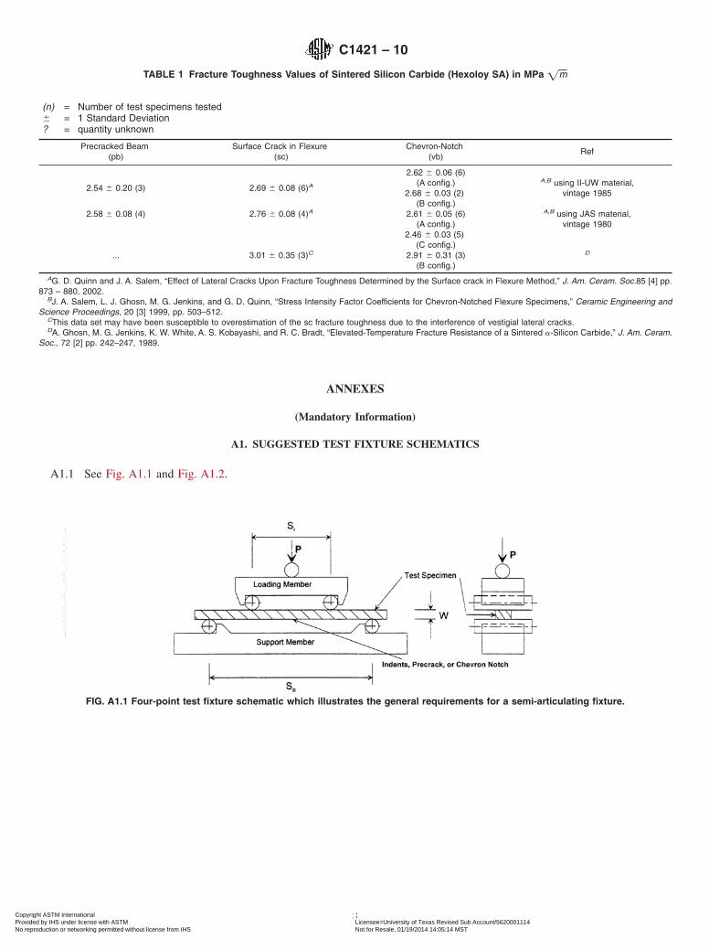
3.2.4 four-point - 1⁄4 point flexure—flexure configurationwhere a beam test specimen is symmetrically loaded at twolocations that are situated one quarter of the overall span, awayfrom the outer two support bearings (see Fig. A1.1) (C1161)
3.2.5 fracture toughness KIc[FL-3/2]—the critical stress in-tensity factor, Mode I, for fracture. It is a measure of theresistance to crack extension in brittle materials.
3.2.6 fracture toughness KIpb[FL-3/2]—the measured stressintensity factor corresponding to the extension resistance of astraight-through crack formed via bridge flexure of a sawnnotch or Vickers or Knoop indentation(s). The measurement isperformed according to the operational procedure herein andsatisfies all the validity requirements. (See Annex A2).
3.2.7 fracture toughness KIsc or KIsc* [FL-3/2]—the mea-sured (KIsc) or apparent (KIsc*) stress intensity factor corre-sponding to the extension resistance of a semi-elliptical crackformed via Knoop indentation, for which the residual stressfield due to indentation has been removed. The measurement isperformed according to the operational procedure herein andsatisfies all the validity requirements. (See Annex A3).
3.2.8 fracture toughness KIvb[FL-3/2]—the measured stressintensity factor corresponding to the extension resistance of astably-extending crack in a chevron-notched test specimen.The measurement is performed according to the operationalprocedure herein and satisfies all the validity requirements.(See Annex A4).
3.2.9 minimum stress-intensity factor coeffıcient, Y*min—theminimum value of Y* determined from Y* as a function ofdimensionless crack length, a = a/W.
3.2.10 pop-in—The sudden formation or extension of acrack without catastrophic fracture of the test specimen,apparent from a force drop in the applied force-displacement
3 Available from National Institute of Standards and Technology (NIST), 100Bureau Dr., Stop 1070, Gaithersburg, MD 20899-1070, http://www.nist.gov.
NOTE 1—The figures on the right show the test specimen cross sections and crack types. Four-point loading may be used with all three methods.Three-point may be used with the pb and vb specimens.
FIG. 1 The Three Test Methods
C1421 – 10
2Copyright ASTM International Provided by IHS under license with ASTM Licensee=University of Texas Revised Sub Account/5620001114
Not for Resale, 01/19/2014 14:05:14 MSTNo reproduction or networking permitted without license from IHS
3.2.12.1 Discussion—The mode of crack extension (stableor unstable) depends on the compliance of the test specimenand test fixture; the test specimen and crack geometries;R-curve behavior of the material; and susceptibility of thematerial to slow crack growth.
3.2.13 three-point flexure—flexure configuration where abeam test specimen is loaded at a location midway betweentwo support bearings (see Fig. A1.2) (C1161)
3.3.41 Yd—stress intensity factor coefficient at the deepestpart of a surface crack, sc method, Eq A3.2
3.3.42 Ys—stress intensity factor coefficient at the intersec-tion of the surface crack with the test specimen surface, scmethod, Eq A3.6
4. Summary of Test Methods
4.1 These methods involve application of force to a beamtest specimen in three- or four-point flexure. The test specimenis very similar to a common flexural strength test specimen.The test specimen either contains a sharp crack initially (pb, sc)or develops one during loading (vb). The equations forcalculating the fracture toughness have been established on thebasis of elastic stress analyses of the test specimen configura-tions. Specific sizes are given for the test specimens and theflexure fixtures. Some are shown in Fig. 2. Annex A2-AnnexA4 have more specific information and requirements for eachmethod.
4.2 Each method has advantages and disadvantages that arelisted in the following three paragraphs. These factors may beconsidered when choosing a test method. Nuances and impor-tant details for each method are covered in the specificannexes. Experience with a method increases the chances ofobtaining successful outcomes. Some trial and error may benecessary with a new material or the first time a method isused, so it is wise to prepare extra test specimens. Backgroundinformation concerning the basis for development of these testmethods may be found in Refs. (1-6).
4.3 Precracked Beam Method—A straight-through precrackis created in a beam test specimen via the bridge-flexuretechnique. In this technique the precrack is extended frommedian cracks associated with one or more Vickers or Knoop
C1421 – 10
3Copyright ASTM International Provided by IHS under license with ASTM Licensee=University of Texas Revised Sub Account/5620001114
Not for Resale, 01/19/2014 14:05:14 MSTNo reproduction or networking permitted without license from IHS
indentations or a shallow saw notch. The fracture force of theprecracked test specimen as a function of displacement oralternative (for example, time, back-face strain, or actuatordisplacement) in three- or four-point flexure is recorded foranalysis. The fracture toughness, KIpb, is calculated from thefracture force, the test specimen size and the measured pre-crack size. Advantages of this method are that it uses a classicfracture configuration and the precracks are large and not toodifficult to measure. A disadvantage is that a special bridgeprecracking fixture is required to pop in a precrack. A welldesigned and well crafted bridge precracking fixture is neededto obtain good precracks. Another disadvantage is that largecompression loads are needed to pop in the precrack. Anotherminor disadvantage is that once precracked, the test specimenmust be handled with care since only a small force is necessaryto break it. The precrack size must be measured. This is notdifficult for most ceramics, but dye penetration techniques maybe needed for some materials (e.g., those with coarse grainmicrostructures) if the precrack does not stand out clearly.
4.4 Surface Crack in Flexure Method—A beam test speci-men is indented with a Knoop indenter and polished (or handground), until the indent and associated residual stress field areremoved. The fracture force to break the test specimen isdetermined in four-point flexure and the fracture toughness,KIsc, is calculated from the fracture force, the test specimensize, and the measured precrack size. An advantage of thismethod is that the precracks are very small and may not bemuch larger the natural strength limiting flaws in the material,so the measured fracture toughness is appropriate for the sizescale of the natural flaws. A disadvantage of this method is thatfractographic techniques are required to measure the smallprecracks and some skill and fractographic equipment isneeded. Another disadvantage is that this method will not work
on very soft or porous ceramics since precracks will not formbeneath the indenter that is used to pop in a precrack. Themethod also will not work in materials whose rough micro-structure prevents the measurement of the precrack.
4.5 Chevron-Notched Beam Method—A chevron-notchedbeam is loaded in either three- or four-point flexure. Appliedforce versus displacement or an alternative (for example, time,back-face strain, or actuator displacement) is recorded in orderto detect unstable fracture, since the test is invalid for unstableconditions. The fracture toughness, KIvb, is calculated from themaximum force applied to the test specimen after extension ofthe crack in a stable manner. The crack forms during theloading sequence. One major advantage of this method is thatit is not necessary to measure the crack size. On the other hand,it is essential that stable crack extension be obtained during thetest. This may be difficult for some ceramics with large elasticmoduli and small fracture toughness values. The chevron notchmust be machined very carefully as described in this method inorder to facilitate stable crack extension and also to satisfy therequirements for a valid test result. A stiff machine/loadtrain/fixture is often necessary to obtain stable crack extension.
NOTE 2—The fracture toughness of many ceramics varies as a functionof the crack extension occurring up to the relevant maximum force. Theactual crack extension to achieve the minimum stress intensity factorcoefficient (Y*min) of the chevron notch configurations described in thismethod is 0.68 to 0.93 mm. This is likely to result in a fracture toughnessvalue in the upper region of the R-curve.
5. Significance and Use
5.1 Fracture toughness, KIc, is a measure of the resistance tocrack extension in a brittle material. These test methods may beused for material development, material comparison, qualityassessment, and characterization.
NOTE 1—Other three-point and four-point spans are permitted for the sc and pb methods.FIG. 2 Primary Test Specimen and Fixture Configurations: General Schematic
C1421 – 10
4Copyright ASTM International Provided by IHS under license with ASTM Licensee=University of Texas Revised Sub Account/5620001114
Not for Resale, 01/19/2014 14:05:14 MSTNo reproduction or networking permitted without license from IHS
5.2 The pb and the vb fracture toughness values provideinformation on the fracture resistance of advanced ceramicscontaining large sharp cracks, while the sc fracture toughnessvalue provides this information for small cracks comparable insize to natural fracture sources. Cracks of different sizes maybe used for the sc method. If the fracture toughness values varyas a function of the crack size it can be expected that KIsc willdiffer from KIpb and KIvb.
6. Interferences
6.1 R-curve—The microstructural features of advanced ce-ramics can cause rising R-curve behavior. For such materialsthe three test methods are expected to result in differentfracture toughness values. These differences are due to theamount of crack extension prior to the relevant maximum testforce, Pmax, or they are due to the details of the precrackingmethods. For materials tested to date the fracture toughnessvalues generally increase in the following order: KIsc, KIpb, KIvb
(7). However, there is insufficient experience to extend thisstatement to all materials. In the analysis of the vb method it isassumed that the material has a flat (no) R-curve. If significantR-curve behavior is suspected, then the sc method should beused for estimates of small-crack fracture toughness, whereasthe vb test may be used for estimates of longer-crack fracturetoughness. The pb fracture toughness may reflect either short-or long-crack length fracture toughness depending on theprecracking conditions. For materials with a flat (no) R-curvethe values of KIpb, KIsc, and KIvb are expected to be the same.NIST Standard Reference Material 2100 has a flat R-curve andKIpb = KIsc = KIvb.
6.2 Time-Dependent Phenomenon and EnvironmentalEffects—The values of KIpb, KIsc, KIvb, for any material can befunctions of test rate because of the effects of temperature orenvironment. Static forces applied for long durations can causecrack extension at KI values less than those measured in thesemethods. The rate of, and level at which, such crack extensionoccurs can be changed by the presence of an aggressiveenvironment, which is material specific. This time-dependentphenomenon is known as slow crack growth (SCG) in theceramics community. SCG can be meaningful even for therelatively short times involved during testing and can lead tomeasured fracture toughness values less than the inherentresistance in the absence of environmental effects. This effectmay be significant even at ambient conditions and can often beminimized or emphasized by selecting a fast or slow test rate,respectively, or by changing the environment. The recom-mended testing rates specified are an attempt to limit environ-mental effects.
6.3 Stability—This standard permits measurements of frac-ture toughness whereby the crack propagates unstably (sc andpb methods) or stably (sc, pb, vb). The stiffness of the testset-up can affect whether the crack grows stably or unstably.There is limited data that suggests a stably propagating crackmay give a slightly lower fracture toughness value than anunstably propagating crack (1-3).
Processing details, service history, and environment mayalter the fracture toughness of the material.
6.4 Processing details, service history, and environmentmay alter the fracture toughness of the material.
7. Apparatus
7.1 Testing—Use a testing machine that has provisions forautographic recording of force applied to the test specimenversus either test specimen centerline deflection or time. Theforce accuracy of the testing machine shall be in accordancewith Practice E4.
7.2 Deflection Measurement—Deflection measurements areoptional, but if determined, measure test specimen deflectionfor the pb and vb close to the crack. The deflection gaugeshould be capable of resolving 1310−3 mm (1 µm) whileexerting a contacting force of less than 1 % of the maximumtest force, Pmax.
NOTE 3—If actuator displacement (stroke) is used to infer deflection ofthe test specimen for the purposes of assessing stability, caution is advised.Actuator displacement (stroke), although sometimes successfully used forthis purpose (9), may not be as sensitive to changes of fracture behaviorin the test specimen as measurements taken on the test specimen itself,such as back-face strain, load-point displacement, or displacement at thecrack plane (10).
7.3 Recording Equipment—Provide a means for automati-cally recording the applied force-displacement or load-time testrecord, (such as a X-Y recorder). For digital data acquisitionsampling rates of 500 Hz or greater are recommended.
7.4 Fixtures—The pb and vb test specimens may be testedin either three-point or four-point fixtures. Annex A2 andAnnex A3 give the recommended span sizes for these twomethods, respectively. sc test specimens shall only be tested infour-point fixtures. Bend fixtures designed for flexural strengthtesting in accordance with Test Method C1161 are suitable, butthis test method allows spans and configurations not in C1161.A bridge precracking fixture is also necessary for the pbmethod. It is described in Annex A2.
NOTE 4—Hereafter in this document the term four-point flexure willrefer to the specific case of 1⁄4-(that is, quarter) point flexure.
7.4.1 The four-point test fixture (see Fig. A1.1) for the pb,vb, or sc methods shall conform to the general fixture require-ments of Test Method C1161. The recommended outer andinner spans are So = 40 mm and Si = 20 mm, respectively, butthis standard allows other span sizes provided that the mini-mum outer and inner spans shall be So = 20 mm and Si = 10mm, respectively. The outer rollers shall be free to rolloutwards and the inner rollers shall be free to roll inwards.Place the rollers initially against their stops and hold them inposition by low-tension springs or rubber bands or magnets.Roller pins shall have a hardness of 40 Rockwell C or greater.
7.4.2 The length of each roller shall be at least three timesthe test specimen dimension, B. The roller diameter shall be 4.56 0.5 mm. The rollers shall be parallel to each other within0.015 mm over either the length of the roller or a length of 3Bor greater.
7.4.3 If the test specimen parallelism requirements set forthin Fig. A2.1 and Fig. A3.1 are not met, use a fully-articulatingfixture as described in C1161.
7.4.4 The fixture shall be capable of maintaining the testspecimen alignment to the tolerances specified in AnnexA2-Annex A4.
7.4.5 A three-point test fixture (see Fig. A1.2) may be usedfor the vb and pb methods. For the pb method, use an outer
C1421 – 10
5Copyright ASTM International Provided by IHS under license with ASTM Licensee=University of Texas Revised Sub Account/5620001114
Not for Resale, 01/19/2014 14:05:14 MSTNo reproduction or networking permitted without license from IHS
span, So, between 16 and 40 mm. Since W = 4 mm (the top tobottom dimension of the test specimen parallel to the cracklength), then the fixture span to specimen size ratio is: 4 #So
W # 10 . For the vb method, W can range from 4 mm to 6.35
mm depending on the specimen type in Annex A4. Choose an
outer span, So, such that 4 #So
W # 10 . The outer two rollers
shall be free to roll outwards to minimize friction effects. Themiddle flexure roller shall be fixed. Alternatively, a roundedknife edge with diameter in accordance with 7.4.2 may be usedin place of the middle roller.
NOTE 5—A stiff test system with displacement control and a stiff loadtrain may be required to obtain stable crack extension for the vb test.Stable crack extension is essential for a valid vb test. A test systemcompliance of less than or equal to 4.43 3 10−5 m/N (including load celland fixtures) is adequate for most vb tests. Stable crack extension is notrequired for the pb test, but if it is desired, then a stiff load train may berequired. See Refs. (8) and (9).
7.5 Dimension-Measuring Devices—Micrometers and otherdevices used for measuring test specimen dimensions shall beaccurate and precise to 0.0025 mm or better. Flat, anvil-typemicrometers with resolutions of 0.0025 or less shall be used fortest specimen dimensions. Ball-tipped or sharp-anvil microme-ters are not recommended as they may damage the testspecimen surface by inducing localized cracking. Non-contacting (for example, optical comparator, light microscopy,etc.) measurements are recommended for crack, pre-crack ornotch measurements, or all of these.
7.6 A conventional hardness testing machine is needed forthe sc method in order to make an indentation-induced pre-crack. A conventional hardness machine may also be used formaking a starter flaw for pb test specimens.
7.7 A bridge precracking fixture is needed for precrackingpb specimens. See Annex A2.
8. Test Specimen Configurations, Dimensions andPreparation
8.1 Test Specimens—Three precrack configurations areequally acceptable: a straight-through pb-crack, a semi-elliptical sc-crack, or a vb-chevron notch. These configurationsare shown in Figs. 1 and 2. Details of the crack geometry, thespecimen dimensions, and preparation requirements are givenin Annex A2 for the pb, Annex A3 for the sc, and Annex A4 forthe vb.
NOTE 6—A typical “plastic” (or deformation) zone, if such exists, is nogreater than a fraction of a micrometer in most ceramics, thus the specifiedsizes are large enough to meet generally-accepted plane strain require-ments at the crack tip from a plasticity viewpoint.
9. General Procedures for Test Methods and Calculations
9.1 Number of Tests—Complete a minimum of five validtests for each material and testing condition. It is prudent toprepare more than 5 test pieces. This will provide specimensfor practice tests to determine the best precracking conditionsand also provide specimens to make up for unsuccessful orinvalid tests. More specimens are needed if environment,testing rate, or precrack sizes will be varied.
9.2 Valid Tests—A valid individual test is one which meetsall the general testing requirements in 9.2.1, and all the specifictesting requirements for a valid test of the particular testmethod as specified in the appropriate annex.
9.2.1 A valid test shall meet the following general require-ments.
9.2.1.1 Test machine shall have provisions for autographicrecording of force versus deflection or time, and the testmachine shall have an accuracy in accordance with Practice E4(7.1).
9.2.1.2 Test fixtures shall comply with specifications of 7.4.9.2.1.3 Dimension-measuring devices shall comply with
specifications of 7.5.9.3 Environmental Effects—If susceptibility to environmen-
tal degradation, such as slow crack growth, is a concern, testsshould be performed and reported at two different test rates, orin appropriately different environments. Testing in an inertenvironment (dry nitrogen, argon, or vacuum) can eliminateenvironmental effects. Susceptibility to slow crack growth canbe assessed by testing at two different testing rates in an air orwater environment. The rates should differ by two to threeorders of magnitude (or greater), however, attainment of stablecrack extension in vb may be difficult at high rates. Alterna-tively, the susceptibility can be assessed by choosing differentenvironments such that the expected effect is small in one case(for example, inert dry nitrogen) and large in the other case(that is, water vapor). If an effect of the environment isdetected, select the fracture toughness values measured at thegreater test rates or in the inert environment. An example of theeffect of environment on the fracture toughness of alumina isgiven in Refs (10 )and (31).
9.4 R-curve—When rising R-curve behavior is to be docu-mented, two different test methods with different amounts ofstable crack extension should be used and the results com-pared. The pb and sc tests typically have less stable crackextension than the vb test.
9.5 Test Specimens and Fracture Experiments— Specifictest specimen measurements, procedures, and calculations arein Annex A2-Annex A4.
9.6 Test Rate—Test the test specimen so that one of the testrates determined in 9.3 will result in a rate of increase in stressintensity factor between 0.1 and 2.75 MPa =m/s. Appliedforce, or displacement (actuator or stroke) rates, or both,corresponding to these stress intensity factor rates are dis-cussed in the appropriate annex. Other test rates are permittedif environmental effects are suspected in accordance with 9.3.
9.7 Humidity and Temperature—Measure the temperatureand humidity according to Test Method E337.
10. Report
10.1 For each test specimen report the following informa-tion:
10.1.1 Test specimen identification,10.1.2 Form of product tested, and materials processing
information, if available,10.1.3 Mean grain size, if available, by Test Method E112 or
other appropriate method,10.1.4 Environment of test, relative humidity, temperature,10.1.5 Test specimen dimensions: B and W,
C1421 – 10
6Copyright ASTM International Provided by IHS under license with ASTM Licensee=University of Texas Revised Sub Account/5620001114
Not for Resale, 01/19/2014 14:05:14 MSTNo reproduction or networking permitted without license from IHS
10.1.5.1 For the pb test specimen crack length, a, and notchthickness, t, if applicable,
10.1.5.2 For the sc test specimen the crack dimensions a and2c,
10.1.5.3 For the vb test specimen the notch parameters, a0
and a11 and a12 and the notch thickness, t,10.1.6 Test fixture specifics,10.1.6.1 Whether the test was in three- or four-point flexure,10.1.6.2 Outer span, So, and inner span (if applicable), Si,10.1.7 Applied force or displacement rate,10.1.8 Measured inclination of the crack plane as specified
in the appropriate annex,10.1.9 Relevant maximum test force, Pmax, as specified in
the appropriate annex,10.1.10 Testing diagrams (for example, applied force vs.
displacement) as required,10.1.11 Number of test specimens tested and the number of
valid tests,10.1.12 Fracture toughness values for each valid test with a
statement confirming that all tests were indeed valid,10.1.13 Additional information as required in the appropri-
ate annex, and10.2 Mean and standard deviation of the fracture toughness
for each test method used.10.3 Crack plane and direction of crack propagation as
appropriate (see Appendix X5).
11. Precision and Bias
11.1 Precision—The precision of a fracture toughness mea-surement is a function of the precision of the various measure-ments of linear dimensions of the test specimen and testfixtures, and the precision of the force measurement. Thewithin-laboratory (repeatability) and between-laboratory (re-
producibility) precisions of some of the fracture toughnessprocedures in this test method have been determined frominter-laboratory test programs (13, 14). More informationabout the precisions of the three test methods are in theAnnexes A2 – A4.
11.2 Bias—Standard Reference Material (SRM) 2100 fromthe National Institute of Standards and Technology may beused to check for laboratory test result bias. The laboratoryaverage value may be compared to the certified reference valueof fracture toughness of 4.57 MPa=m 6 0.11 MPa=m (or 2.3%) at a 95 % confidence level. SRM 2100 is a set of five siliconnitride beam test specimens. Identical results are obtained withthe three test methods in this standard when used with SRM2100.
11.3 Variation in Results with Test Method for OtherMaterials—As discussed in 1.4, 6.1 and 6.2, for some materi-als KIpb, KIsc, and KIvb values may differ from each other (forexample, (15)). Nevertheless, a comparison of test resultsobtained by the three different methods is instructive. Suchcomparisons are shown in Table 1. The experimental proce-dures used in the studies cited in Table 1 varied somewhat andwere not always in accordance with this standard, although thedata are presented here for illustrative purposes. Table 1contains results for sintered silicon carbide, an advancedceramic which is known to be insensitive to environmentaleffects in ambient laboratory conditions. This material is alsoknown to have a fracture toughness independent of crack size(flat R-curve).
AG. D. Quinn and J. A. Salem, “Effect of Lateral Cracks Upon Fracture Toughness Determined by the Surface crack in Flexure Method,” J. Am. Ceram. Soc.85 [4] pp.873 – 880, 2002.
BJ. A. Salem, L. J. Ghosn, M. G. Jenkins, and G. D. Quinn, “Stress Intensity Factor Coefficients for Chevron-Notched Flexure Specimens,” Ceramic Engineering andScience Proceedings, 20 [3] 1999, pp. 503–512.
CThis data set may have been susceptible to overestimation of the sc fracture toughness due to the interference of vestigial lateral cracks.DA. Ghosn, M. G. Jenkins, K. W. White, A. S. Kobayashi, and R. C. Bradt, “Elevated-Temperature Fracture Resistance of a Sintered a-Silicon Carbide,” J. Am. Ceram.
Soc., 72 [2] pp. 242–247, 1989.
FIG. A1.1 Four-point test fixture schematic which illustrates the general requirements for a semi-articulating fixture.
C1421 – 10
8Copyright ASTM International Provided by IHS under license with ASTM Licensee=University of Texas Revised Sub Account/5620001114
Not for Resale, 01/19/2014 14:05:14 MSTNo reproduction or networking permitted without license from IHS
A2. PROCEDURES AND SPECIAL REQUIREMENTS FOR THE PRECRACKED BEAM METHOD
A2.1 Test Specimen
A2.1.1 Test Specimen Size—The test specimen shall be 3 by4 mm in cross section with the tolerances shown in Fig. A2.1.The test specimen may or may not contain a saw-cut notch. Forboth four-point and three-point flexure tests the length shall beat least 20 mm but not more than 50 mm. Test specimens oflarger cross section can be tested as long as the proportionsgiven in Fig. A2.1 are maintained.
A2.1.2 Test Specimen Preparation—Test specimens pre-pared in accordance with the Procedure of Test Method C1161,test specimen Type B, are suitable as summarized in thefollowing paragraphs, A2.1.2.1-A2.1.2.3. Alternative proce-dures may be utilized provided that unwanted machiningdamage and residual stresses are minimized. Report anyalternative test specimen preparation procedure in the testreport.
A2.1.2.1 All grinding shall be done with an ample supply ofappropriate filtered coolant to keep workpiece and wheelconstantly flooded and particles flushed. Grinding shall be in atleast two stages, ranging from coarse to fine rates of materialremoval. All machining shall be in the surface grinding mode
parallel to the test specimen long axis. The stock removal rateshall not exceed 0.02 mm per pass to the last 0.06 mm per face.
A2.1.2.2 Perform finish grinding with a diamond-grit wheelof 320 grit or finer. No less than 0.06 mm per face shall beremoved during the final finishing phase, and at a rate of notmore than 0.002 mm per pass.
A2.1.2.3 The two end faces need not be precision machined.The four long edges shall be chamfered at 45° a distance of0.1260.03 mm, or alternatively, they may be rounded with aradius of 0.15 6 0.05 mm as shown in Fig. A2.1. Edgefinishing shall be comparable to that applied to the testspecimen surfaces. In particular, the direction of the machiningshall be parallel to the test specimen long axis.
A2.1.2.4 The notch, if used, should be made in the 3-mmface, should be less than 0.10 mm in thickness, and shouldhave a length of 0.12 # a/W # 0.30.
A2.1.3 It is recommended that at least ten test specimens beprepared. This will provide test specimens for practice tests todetermine the best precracking parameters. It will also providemake-up test specimens for unsuccessful or invalid tests so asto meet the requirements of 9.1 and 9.2.
FIG. A1.2 Three-point test fixture schematic which illustrates thegeneral requirements of the test fixture.
FIG. A2.1 Dimensions of Rectangular Beam
C1421 – 10
9Copyright ASTM International Provided by IHS under license with ASTM Licensee=University of Texas Revised Sub Account/5620001114
Not for Resale, 01/19/2014 14:05:14 MSTNo reproduction or networking permitted without license from IHS
A2.1.4 Measure the cross section dimensions B and W towithin 0.002 mm near the middle of the test piece.
A2.2 Apparatus
A2.2.1 General—This fracture test is conducted in eitherthree- or four-point flexure. A displacement measurement (oralternative) is required for fracture testing in order to detectsigns of crack extension.
A2.2.2 Bridge Precracking Fixture—The configurationused for precracking is different from that used for the actualfracture test. A bridge compression fixture is used to create aprecrack from an indentation crack or from a sawed notch. Thefixture consists of a square support lower plate with a centergroove (which is bridged by the test specimen) and a toppusher plate with a bonded pusher plate insert (for example,silicon nitride). The lengths of both plates (L1 in Fig. A2.2) areequal to each other and are less than or equal to 18 mm. Thesurfaces that contact the test specimen are of a material with anelastic modulus greater than 300 GPa. The support plate canhave several grooves (L2 in Fig. A2.2) ranging from 2 to 6 mmin width. Alternatively, several parts, each with a differentgroove width can be used. A fixture design is shown in Fig.A2.2. The support and pusher plates shall be parallel within0.01 mm. Alternatively, a self-aligning fixture can be used.
A2.2.3 Fracture Test Fixture—The general principles of thefour-and three-point test fixture are detailed in 7.4 and illus-trated in Fig. A1.1 and Fig. A1.2, respectively. For three-point
flexure, choose the outer support span such that 4 #So
W # 10.
A2.2.3.1 For four-point flexure, the plane of the crack shallbe located within 1.0 mm of the midpoint between the twoinner rollers, Si. Measure the inner and outer spans to within0.1 mm. Align the midpoint of the two inner rollers relative tothe midpoint of the two outer rollers to within 0.1 mm. Seat thedisplacement indicator (if used) close to the crack plane.Alternatively, use actuator (or crosshead) displacement(stroke), back-face strain, or a time sweep.
A2.2.3.2 For three-point flexure, measure the span within0.5 % of So. Align the center of the middle roller so that its lineof action shall pass midway between the two outer rollerswithin 0.1 mm. Seat the displacement indicator close to thecrack plane if used. Alternatively, monitor actuator (or cross-head) displacement, back-face strain, or a time sweep.
NOTE A2.1—For short spans (for example, So = 16 mm) and So/W = 4.0in three-point flexure, errors of up to 3 % in determining the critical modeI stress intensity factor may occur because of misalignment of the middleroller, misalignment of the support span, or angularity of the precrack atthe extremes of the tolerances allowed (11, 12) .
A2.2.3.3 This method permits either unstable or stable crackextension during the fracture test. When the critical stressintensity, KIpb, is reached, the crack propagates unstablythrough the test piece. This is acceptable and the normal waythis test method is performed. If stable extension is desired,extra attention to the test setup is needed and very stiff testfixtures and load train may be necessary. The stability (that is,the tendency to obtain stable crack extension) of the test setupis affected not only by the test system compliance (see Note 7)but also by the test specimen dimensions, the So/W ratio, andthe elastic modulus of the material (8, 9). The degree ofstability can be detected easily with back-face strain.
NOTE A2.2—There is a limited amount of data indicating unstable testsmay result in slightly greater fracture toughness values than those fromtests with stable crack extension (8, 9). If stable crack extension cannot beobtained with four-point flexure, it may be possible to obtain stable crackextension by using a three-point flexure configuration in a stiff test setup.Nonlinearity of the initial part of the applied force-displacement curve(sometimes called “windup”) is usually an artifact of the test setup andmay not be indicative of material behavior. This type of nonlinearity doesnot contribute directly to instability unless such nonlinearity extends to theregion of maximum force.
A2.3 Procedure
A2.3.1 Preparation of Crack Starter—Either the machinednotch (Fig. A2.3a), or one or more Vickers or Knoop indenta-tions, (Fig. A2.3b) act as the crack starter. For a test specimenwithout a notch, create a Vickers indentation in the middle ofthe surface of the 3-mm face (Fig. A2.3b). Additional inden-tations can be placed on both sides of the first indentation,aligned in the same plane and perpendicular to the longitudinalaxis of the test specimen, as shown in Fig. A2.3b. One of thediagonals of each of the indentations shall be aligned parallelto the test specimen length. The indentation force shall notexceed 100 N. While an indentation crack is physicallynecessary for subsequent generation of a pop-in crack, cracksemanating from the corners of the indentation may or may notbe visible depending on the characteristics and finish of the testmaterial. Alternatively, a Knoop indentation may also be usedas a crack starter in which case, the long axis of the indentationshall be perpendicular to the longitudinal axis of the testspecimen. If, for a particular test material, a pop-in crack doesnot form from the indent produced by the 100 N indentation,then it may be necessary to first form a saw notch as a crackstarter.
NOTE A2.3—The 100 N indentation force limit is intended to minimize
potential residual tensile stresses which could influence the fractureresults. If residual stresses from the indentation are suspected to haveaffected the fracture results, the indentations may be removed by polish-ing, hand grinding or grinding after the precrack has been formed(A2.3.2). Annealing may be used provided that the crack tip is not bluntednor the crack tip/planes healed.
A2.3.2 Formation of Precrack—Thoroughly clean the testspecimen and contacting faces of the bridge compressionfixture. Place the test specimen in the compression fixture withthe surface containing the notch or indent(s) over the grooveand the notch or indent(s) centered between the edges of thegroove. Load the test specimen in the compression fixture atrates less than 1000 N/s until a distinct pop-in sound is heardand/or until a pop-in precrack is seen. At high force rates it maynot be possible to discern the force drop in the appliedforce-displacement curve as discussed in 3.2.10. A stethoscopeor other acoustic transducer can also be used to detect thepop-in sound. A traveling microscope is also recommended toview the pop-in crack as the pop-in sound is not alwaysdiscernible. In some materials it is difficult to see a precrack onthe side of the test specimens. Lapping of the side surface oruse of a dye penetrant, or both, (see A2.3.2.1) can helpdelineate the crack. Stop loading immediately after pop-in.Measure the length of the pop-in crack on both side surfaces.The precrack length should be between 0.35 and 0.60W.
NOTE A2.4—For materials with a rising R-curve the KIpb value mightbe artificially high if the precrack is not stopped immediately after pop-in.The force rate during pop-in may influence the crack/microstructureinteraction and may affect the result.
NOTE A2.5—Caution: Use care not to overload the testing machine orload cell.
A2.3.2.1 A drop of the dye penetrant can be placed onindentations or saw notch. Upon formation of the precrack, thepenetrant will be drawn into the crack and will show on theside surface of the test specimen upon unloading.
NOTE A2.6—Caution: Use care to ensure that dye penetrants are dry(for example, by heating the specimen) or do not promote corrosion orslow crack growth, prior to fracture testing to preclude undesired slowcrack growth or undesired crack face bonding.
A2.3.3 Choice of Groove—The pop-in precrack length is aresult of the selected indent force and groove size of thecompression fixture. These two parameters need to be deter-mined by trial and error. It has been shown that the pop-inprecrack length decreases with increasing indent force and withdecreasing groove (span) size (16, 17).
A2.3.4 Fracture Test—Insert the test specimen into theflexure fixture. Align the test specimen so that it is centereddirectly below the axis of the force application. Align the tip ofthe crack with the centerline of the middle roller in thethree-point flexure fixture within 0.5 mm or within 1.0 mm ofthe midpoint between the two inner rollers, Si, of the four-pointflexure fixture. Seat the displacement indicator (if used) closeto the crack plane. Alternatively, monitor actuator (or cross-head) displacement (stroke), back-face strain, or a time sweep.Test the test specimen in actuator displacement (stroke) controlat a rate in agreement with 9.6. Record applied force versusdisplacement or alternative (for example, actuator displace-ment (stroke), load-point displacement, displacement of thetest specimen at the crack plane), back-face strain (10) or time.
NOTE A2.7—Generally, actuator displacement (stroke) rates of 0.0005to 0.01 mm/s for test specimens with a 3 3 4 mm cross section providestress intensity factor rates in accordance with 9.6.
NOTE A2.8—Actuator displacement (stroke) may not be as sensitive tochanges of fracture behavior in the test specimen as measurements takenon the test specimen itself, such as back-face strain, load-point displace-ment, or displacement at the crack plane (10).
NOTE A2.9—The requirement for centering the test specimen is mucheasier to fulfill for a four-point flexure test (18). A three-point flexure testrequires that the crack plane be centered accurately in the test fixture.
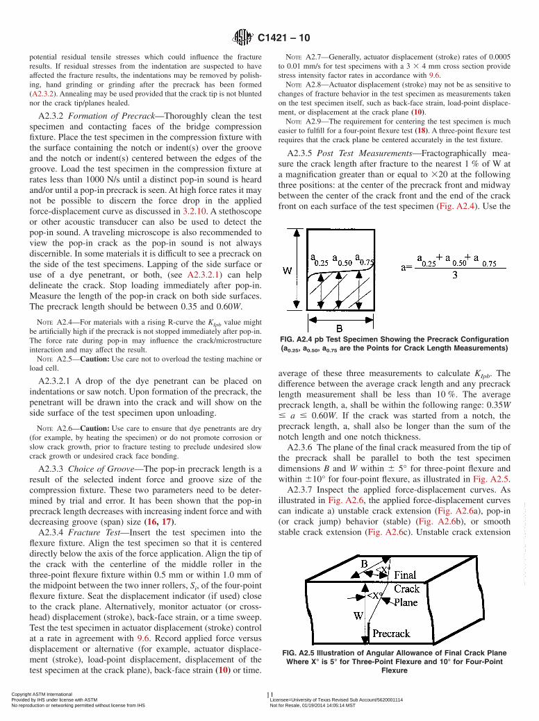
A2.3.5 Post Test Measurements—Fractographically mea-sure the crack length after fracture to the nearest 1 % of W ata magnification greater than or equal to 320 at the followingthree positions: at the center of the precrack front and midwaybetween the center of the crack front and the end of the crackfront on each surface of the test specimen (Fig. A2.4). Use the
average of these three measurements to calculate KIpb. Thedifference between the average crack length and any precracklength measurement shall be less than 10 %. The averageprecrack length, a, shall be within the following range: 0.35W# a # 0.60W. If the crack was started from a notch, theprecrack length, a, shall also be longer than the sum of thenotch length and one notch thickness.
A2.3.6 The plane of the final crack measured from the tip ofthe precrack shall be parallel to both the test specimendimensions B and W within 6 5° for three-point flexure andwithin 610° for four-point flexure, as illustrated in Fig. A2.5.
A2.3.7 Inspect the applied force-displacement curves. Asillustrated in Fig. A2.6, the applied force-displacement curvescan indicate a) unstable crack extension (Fig. A2.6a), pop-in(or crack jump) behavior (stable) (Fig. A2.6b), or smoothstable crack extension (Fig. A2.6c). Unstable crack extension
FIG. A2.4 pb Test Specimen Showing the Precrack Configuration(a0.25, a0.50, a0.75 are the Points for Crack Length Measurements)
FIG. A2.5 Illustration of Angular Allowance of Final Crack PlaneWhere X° is 5° for Three-Point Flexure and 10° for Four-Point
Flexure
C1421 – 10
11Copyright ASTM International Provided by IHS under license with ASTM Licensee=University of Texas Revised Sub Account/5620001114
Not for Resale, 01/19/2014 14:05:14 MSTNo reproduction or networking permitted without license from IHS
may give greater fracture toughness values than those fromtests with stable crack extension.
A2.3.8 If there is evidence of environmentally-assisted slowcrack growth then it is advisable to run additional tests in aninert environment. Alternatively, additional tests may be donein laboratory ambient conditions at faster or slower test ratesthan those specified in this standard in order to determine thesensitivity to test rates. Testing rates that differ by two to threeorders of magnitude or greater than those specified are recom-mended. (See 9.3.)
A2.4 Calculation
A2.4.1 Calculate the fracture toughness, KIpb, for each testspecimen and test configuration.
So = 40.0 mm = 40.0 310−3 m and Si = 20.0 mm = 20.0 310−3
m thena/W = 0.50, f = 0.9382.
where:KIpb = fracture toughness (MPa =m!,f = f(a/W) = function of the ratio a/W for four-point flex-
ure,g = g(a/W) = function of the ratio a/W for three-point
flexure,Pmax = maximum force (N),So = outer span (m),Si = inner span (m),B = side to side dimension of the test specimen
perpendicular to the crack length (depth) asshown in A2.4 (m),
W = top to bottom dimension of the test specimenparallel to the crack length (depth) as shownin A2.4 (m), and
a = crack length as determined in A2.4 (m).
A2.5 Valid Test
A2.5.1 A valid pb test shall meet the following requirementsin addition to the general requirements of these test methods(9.2):
A2.5.1.1 Test specimen size (A2.1.1) shall be 3 by 4 mmwith tolerances as shown in Fig. A2.1 and the length shall beat least 20 mm but not more than 50 mm unless test specimensof larger cross section are used as long as the proportions givenin Fig. A2.1 are maintained.
A2.5.1.2 Test specimen preparation (A2.1.2) shall conformto the procedures of A2.1.2.
A2.5.1.3 Crack starter (A2.3.1) introduced from Vickersindent shall be produced at an indent force # 100 N and oneof the diagonals of each of the indents shall be aligned parallelto the test specimen length.
A2.5.1.4 Pop-in precrack (A2.2.2 and A2.3.2) shall beintroduced using a grooved compression fixture.
A2.5.1.5 Crack length (A2.3.5): difference between averagecrack length and minimum precrack length shall be less than10 % and average precrack length shall be 0.35W < a < 0.6W.
A2.5.1.6 Plane of final crack (A2.3.6) shall be parallel toboth the test specimen dimensions B and W within 6 5° forthree-point flexure and 6 10° for four-point flexure.
A2.6 Reporting Requirements
A2.6.1 In addition to the general reporting requirements of10.1, 10.2 and 10.3 report the following for the pb method.
A2.6.1.1 Mean crack length as measured in A2.3.5 (mm),A2.6.1.2 Each applied force-displacement (time or strain)
diagram,A2.6.1.3 Precracking details, such as the number of indents,
indentation force and the force rate during pop-in.
A2.7 Precision and Bias
A2.7.1 PrecisionThe precision of the pb method depends upon the uncertain-
ties in the measured break load, P; the precrack size, a; thequality of the precrack (e.g., evenness, straightness, residualstresses); the beam dimensions, B and W; the stress intensityfactor coefficient, Y; the quality and alignment of the precrack,and whether any stable crack extension occurs and whether itis detected and measured.
A2.7.1.1 Results from an eighteen-laboratory, internationalround robin conducted under the auspices of the VersaillesAdvanced Materials and Standards (VAMAS) can be used toestimate the precision of the pb method (13, 22, 23) . A gaspressure sintered silicon nitride was tested by procedures thatwere similar to those prescribed in this Test Method. Animportant exception was that specific actuator displacement(stroke) rates were prescribed, rather than stress intensity factorrates. Two actuator displacement (stroke) rates, 0.0166 mm/sand 0.0000833 mm/s were prescribed. This permitted anassessment of whether time-dependent environmental effectswere present. Ten test specimens were tested at each test rate
TABLE A2.1 Coefficients for the Polynomial g(a/W) for Three-point Flexure
TABLE A2.2 Precracked Beam Results from VAMAS Round Robin for Gas-Pressure Sintered Silicon Nitride (13,22,23)
TestRatesmm/sA
Numberof
LaboratoriesB
OverallMean
MPa=m
Repeatability(Within-Laboratory)
Reproducibility(Between-Laboratories)
Std DevMPa=m
95 %limitMPa=m
COVC
%Std DevMPa=m
95 %limitMPa=m
COVC
%0.0166 or(0.0083)
16 5.77 0.26 0.72 4.5 0.51 1.42 8.8
0.000083or
(0.000167,0.000042)
12 5.60 0.26 0.73 4.7 0.40 1.11 7.1
ANumbers in parentheses show alternative test rates that some laboratories used rather than the specified rates.BAt each test rate the results from one laboratory were deleted, due to high within-laboratory (repeatability) scatter.CCoefficient of variation.
C1421 – 10
13Copyright ASTM International Provided by IHS under license with ASTM Licensee=University of Texas Revised Sub Account/5620001114
Not for Resale, 01/19/2014 14:05:14 MSTNo reproduction or networking permitted without license from IHS
by each laboratory. A variety of test fixtures and test rates wereused for precracking. The results were analyzed in accordancewith Practices E177 and E691. The results are given in TableA2.2.
A2.7.1.2 The VAMAS round robin also included pb testingon a zirconia-alumina composite material. Environmentallyassisted crack growth and possible rising R-curve behaviorcaused complications in interpretation of the results as dis-cussed in Ref. (13) .
A2.7.2 Bias
The bias is estimated to be negligible (<1%) when using thepb method for a material with a flat R-curve and which has nosusceptibility to environmentally-assisted slow crack growth.pb data for SRM 2100 are virtually identical agreement with scand vb results.
A2.7.3 A slight loss of accuracy and precision may resultfrom the use of very short 3–point spans as discussed in Ref(12). The precrack angle and middle-roller fixture alignmenttolerances specified in this standard lead to a maximumpossible 3 % error in KI, pb.
A3. PROCEDURES AND SPECIAL REQUIREMENTS FOR THE SURFACE-CRACK IN FLEXURE METHOD
A3.1 Test Specimen
A3.1.1 Test Specimen Size—The test specimen shall be 3 X4 mm in cross section with the tolerances shown in Fig. A3.1.The length shall be 45 to 50 mm. Half length test specimenswith cross-section dimensions of 3 X 4 mm and lengths of 25mm or greater may also be used.
A3.1.2 Test Specimen Preparation—Test specimens pre-pared in accordance with the Procedure of Test Method C1161,test specimen Type B, are suitable as summarized in theA3.1.2.1-A3.1.2.4. Alternative procedures may be utilizedprovided that unwanted machining damage and residualstresses are minimized. Report any alternative test specimenpreparation procedure in the test report.
A3.1.2.1 All grinding shall be done with an ample supply ofappropriate filtered coolant to keep workpiece and wheelconstantly flooded and particles flushed. Grinding shall be in atleast two stages, ranging from coarse to fine rates of materialremoval. All machining shall be in the surface grinding modeparallel to the test specimen long axis. No Blanchard or rotarygrinding shall be used. The stock removal rate shall not exceed0.02 mm per pass to the last 0.06 mm per face. Theseconditions are intended to minimize machining damage orsurface residual stresses which can strongly affect tests using sctest specimens. As the grinding method of Test Method C1161is well established and economical, it is recommended.
A3.1.2.2 For all surfaces except that to be indented performfinish grinding with a diamond-grit wheel of 320 grit or finer.
No less than 0.06 mm per face shall be removed during thefinal finishing phase, and at a rate of not more than 0.002 mmper pass.
A3.1.2.3 The indentation can be placed in either a 3- or4-mm wide flat surface of the beam. The surface need not havean optical quality finish. It need only be flat such that theindentation is not affected by machining striations and marks.For the surface to be indented (either the 3- or 4-mmdimension), a diamond-grit wheel (320 to 500 grit) shall beused to remove the last 0.04 mm at a rate of not more than0.002 mm per pass. Polish, lap or fine grind this face to providea flat, smooth surface for the surface crack. It can alternativelybe ground with a 600-grit or finer wheel, provided that residualstresses are not introduced.
A3.1.2.4 The two end faces need not be precision machined.The four long edges shall be chamfered at 45° a distance of0.12 6 0.03 mm, or alternatively, they may be rounded with aradius of 0.15 6 0.05 mm as shown in Fig. A3.1. Edgefinishing shall be comparable to that applied to the testspecimen surfaces. In particular, the direction of the machiningshall be parallel to the test specimen long axis.
A3.1.3 It is recommended that at least ten and preferablytwenty test specimens be prepared. This will provide testspecimens for practice tests to determine the best indentationforce. It will also provide make up test specimens for unsuc-cessful or invalid tests so as to meet the requirements of 9.1and 9.2.
FIG. A3.1 Dimensions of Rectangular Beam
C1421 – 10
14Copyright ASTM International Provided by IHS under license with ASTM Licensee=University of Texas Revised Sub Account/5620001114
Not for Resale, 01/19/2014 14:05:14 MSTNo reproduction or networking permitted without license from IHS
A3.2.1 General—Conduct this test in four-point flexure. Adisplacement measurement is not required.
A3.2.2 Fracture Test Fixture—The general principles of thefour-point test fixture are detailed in 7.4 and illustrated in A1.1.
A3.3 Procedure
A3.3.1 Precracking—Standard Procedure:A3.3.1.1 Use a Knoop indenter to indent the middle of the
polished surface of the test specimen. Orient the long axis ofthe indent at right angles (within 2°) to the long axis of the testspecimen as shown in Fig. A3.2. Tilt the test specimen 1⁄4 ° to1⁄2 ° as shown in Fig. A3.3. The 1/4° to 1/2° tilt is intended tomake the precrack easier to discern during measurement ofprecrack size after fracture. Use a full-force dwell time of 15 sor more during the indentation cycle. Indentation times longerthan 15 s may be helpful for some materials such as zirconia.A schematic of a resulting precrack is shown in Fig. A3.4 andFig. A3.3.
A3.3.1.2 The indentation force, F, used may have to bedetermined for each different class of material by the use of afew trial test specimens. The force must be great enough tocreate a crack that is greater than the naturally-occurring flawsin the material, but not too great relative to the test specimencross section size, nor so great that extreme impact damageoccurs. Indentation forces of approximately 10 to 20 N aresuitable for very brittle ceramics, 25 to 50 N for medium“tough” ceramics, and 50 to 100 N for very “tough” ceramics.Indentation loads of 100 N –150 N may be necessary formaterials with medium to coarse-grain sizes. In such materials,it is necessary to make large precracks that will stand outagainst the normal microstructural roughness on the fracturesurface. An indentation force of 30 N may be suitable for mostglasses. The Knoop indentation procedure to create a surfacecrack will not be successful on very soft (low hardness) orporous ceramics, since precracks do not form under theindentation. The indentation procedure also may not work onvery “tough” ceramics, since they are resistant to the formationof a crack or the crack is so small that it is removed during thesubsequent material removal step (A3.3.2) to remove theresidual stress and damage zone. A trial specimen may betested to help determine the best indentation load. Indent thenfracture the specimen in the flexure fixtures without removal ofthe indentation and residual stress damage zone. Examine the
fracture surface to confirm that the specimen has fracturedfrom the precrack, that the precrack is discernible, and withinthe prescribed size limits. Do not use the outcome from such atrial test in the final analyses, however, since the residualindentation stresses have not been removed.
A3.3.2 Removal of Indented Zone:A3.3.2.1 Measure the length of the long diagonal, d, of the
Knoop impression to within 0.005 mm. This measurementneed not be done to the precision required for hardnessmeasurements. If Knoop hardness is to be reported, greatercare should be exercised in making the diagonal size measure-ment and in the preparation of the initial test specimen surface.
Calculate the approximate depth, h, of the Knoop impressionas follows:
h 5 d/30 (A3.1)
A3.3.2.2 Measure the initial (pre-polishing) test specimendimension, W, at the indent location to within 0.002 mm. Ahand-held micrometer with a vernier graduation is suitable.
A3.3.2.3 Mark the side of the test specimen with a pencil-drawn arrow in order to indicate the surface with the precrackand its approximate location.
A3.3.2.4 Remove the residual stress damage zone by mildgrinding, hand grinding, or hand polishing with abrasivepapers.
A3.3.2.5 Hand lapping or grinding may be done wet or dry,with the type of procedure reported. Remove an amount ofmaterial that is approximately equal to 4.5 to 5.0 h as shown inFig. A3.5. If there is evidence that this material removal has noteliminated deep lateral cracks, then additional material shouldbe removed as described in A3.3.2.6. The material removalprocess shall not induce residual stresses or excessive machin-ing damage in the test specimen surface. Remove the last 0.005mm with a finer grit (220 to 280 grit) paper with less pressure,so as to minimize polishing damage. Check the test specimendimension, W, frequently during this process. In particular, theevenness of W should be monitored. A hand micrometer shouldbe used to check W at several locations across the specimenwidth B in the vicinity of the indentation. Use a handmicrometer with a resolution of 0.0025 mm or better.
NOTE A3.1—Hand grinding the test specimen with 180 to 220 gritsilicon carbide paper can remove the required amount in 1 to 5 min per testspecimen for many ceramics. Faster removal rates occur when handgrinding dry. Finer-grit (320 to 400 grit) papers are recommended forglasses for both rough- and fine- grinding steps. Diamond impregnatedabrasive disks with 30 µm or finer abrasive may also be used. Handgrinding, hand lapping or hand polishing may not be effective with veryhard ceramics. For very hard ceramics, see A3.3.2.7.
NOTE A3.2—Hand lapping or grinding may make the surface uneven ornot parallel to the opposite test specimen face. This can cause misalign-ments during subsequent testing on test fixtures. If the polished facecannot be maintained parallel to the opposite face within 6 0.015 mm,then fully-articulating fixtures should be used for flexure testing inaccordance with 7.4.3. A slight rounding of the edges of the test specimenfrom hand grinding is usually inconsequential. In a given test specimen,regularly change the orientation of the surface being polished to thelapping disk during material removal steps to minimize unevenness.
NOTE A3.3—Warning: Fine ceramic powders or fragments may becreated if the lapping or hand grinding is done dry. This can create aninhalation hazard if the ceramic contains silica or fine whiskers. Masks orrespirators should be used, or the removal should be done wet.FIG. A3.2 Surface-Crack in Flexure (sc) Test Specimen
C1421 – 10
15Copyright ASTM International Provided by IHS under license with ASTM Licensee=University of Texas Revised Sub Account/5620001114
Not for Resale, 01/19/2014 14:05:14 MSTNo reproduction or networking permitted without license from IHS
NOTE A3.4—Removing 4.5 to 5.0 h eliminates the residual stressdamage zone under the impression, and usually leaves a precrack shapethat has the highest stress intensity factor at the deepest part of theprecrack periphery. The location of the maximum stress intensity can becontrolled by the amount of material removed. The initial precrack underthe Knoop indent is roughly semicircular and Ymax is at the surface. As
material is removed, the precrack becomes more semi-elliptical in shape(or like a section of a circle) and Ymax shifts to the deepest part of theprecrack. If too much material is removed, the remaining precrack will betoo small and fracture will not occur from the precrack. In such casessmaller amounts should be removed, provided that no less than 3 h isremoved. If this step is not adequate to ensure fracture from the precrack,then a greater indent force or the alternative procedure described inAppendix X3 may be used.
A3.3.2.6 After the prescribed amount of material has beenremoved, examine the ground-indented surface for evidence ofremnant lateral cracks. Fig. A3.6 provides guidance. A lowpower reflected light metallurgical optical microscope withmagnifications from 3100 – 3400 may be used to examine theground-indented tensile surface. If there is evidence of rem-nants of lateral cracks, then additional material should beremoved (6h –10h) to ensure that the lateral cracks remnantsare removed. Remnant lateral cracks are more apt to be aproblem with brittle materials (for example, KIsc < 3.0MPa=m) or if larger indentation loads ($ 98 N) are used.
A3.3.2.7 Surface grinding with diamond wheels is alsopermitted as a means to remove the indent and residual stressdamage zone, but it is much more difficult to ensure that thecorrect amount of material has been removed from each testspecimen. There also is a potential for introduction of residualstresses. Machine grinding will be necessary for very hardceramics. If machine grinding is used, use fine wheel grits andsmall removal rates.
A3.3.2.8 If water or a cutting fluid is used, then ensure thatthe test specimen is dry (for example, by heating) prior tofracture testing. There is no consensus on the best conditionsfor drying specimens. Heating in an air or vacuum oven at 100°C – 150 °C for times up to 1 h and then storage in a desiccatorprior to testing may be sufficient.
NOTE 1—The indent and precrack sizes are exaggerated for clarity.FIG. A3.3 The Test Specimen may be Indented at a 1⁄2 ° Tilt in Order to Enhance the Chances of Detecting the Precrack on the
Fractographic Surface During Subsequent Fracture Analysis. The indentation may be introduced in either the narrow 3-mm face or thewide 4-mm face.
FIG. A3.4 a and b Cross Section of sc Test Specimens Showingthe Precrack Configurations for Two Orientations
NOTE 1—Remove 4.5h to 5.0h from the test specimen surface in orderto remove the indent and damage zone.
FIG. A3.5 The Precrack Extends Below the Knoop HardnessImpression, which has Depth, h
C1421 – 10
16Copyright ASTM International Provided by IHS under license with ASTM Licensee=University of Texas Revised Sub Account/5620001114
Not for Resale, 01/19/2014 14:05:14 MSTNo reproduction or networking permitted without license from IHS
A3.3.2.9 Annealing or heat treating to remove the residualstresses under the indent are not permitted by this standard dueto the risk of crack tip blunting, crack healing, or possiblechanges in the microstructure.
A3.3.2.10 Measure and record the final (post-polishing) testspecimen dimensions, B and W, in the vicinity of the precrackto within 0.002 mm.
A3.3.2.11 In some materials a dye penetrant may aidpre-crack detection after the test specimen is fractured. If a dyepenetrant is used, the specimen should be dried thoroughlyprior to fracture.
A3.3.3 Fracture Test—Insert the test specimen into the testfixture as shown in Fig. A3.7, with the surface crack on thetension face, within 1.0 mm of the midpoint between the twoinner rollers, Si, of the four-point test fixture. Align the testspecimen so that it is centered directly below the axis of theforce application. Full length test specimens (45 to 50 mmlength) should be tested on 20 mm X 40 mm test fixtures andhalf length test specimens (~25 mm length) should be tested on10 mm X 20 mm test fixtures. The test specimen may bepreloaded to approximately 25 % of the expected fractureforce. Place cotton, crumbled tissue, or other appropriatematerial under the test specimen to prevent the pieces fromimpacting the fixture upon fracture. Place a thin shield aroundthe fixture to ensure operator safety and to preserve the primaryfracture pieces for subsequent fracture analysis. Test the testspecimen to fracture at rates in accordance with 9.6.
NOTE A3.5—The force rate will range from 10 to 250 N/s for a testspecimen with B=4 mm, W=3 mm, with a precrack size, a, of 100 µm, ona four-point test fixture with So = 40 mm. If the test specimen is tested onedge (B = 3 mm, W = 4 mm), the rates will be 13 - 388 N/s. Rates foralternative geometries and precrack sizes can be estimated from Eq A3.9with an approximation of Y = 1.3. Displacement rates of 0.002 to 0.10mm/s will be suitable for a 3 by 4-mm test specimen with a 100 µmprecrack in the 4-mm (B) face.
A3.3.4 Post Test Measurements—Examine the fracture sur-faces of the test specimen and measure the initial precrackdimensions, a and 2c, as shown in Fig. A3.4 and Fig. A3.3.Fractographic techniques and fractographic skills are neededfor this step (see Appendix X1). If stable crack extension is notdetected, the critical crack size should be the same as theprecrack size. Measure the crack depth, a, to within 0.005 mm(5 µm) or less if possible and the crack width, 2c, to within
0.010 mm (10 µm) or less if possible. If stable crack extensionis detected, measure both the initial and final crack sizes.
A3.3.4.1 The precision of the crack size measurementdepends upon the material and its microstructure, the clarity ofthe crack, and the mode of viewing. In many instances, thecomputed fracture toughness is not very sensitive to theprecision of the crack size measurement as discussed inReferences 14 and 24. Depending upon the crack sizes andspecimen geometries, satisfactory estimates of fracture tough-ness may be obtained even with crack size measurements thatare less precise than suggested above. The optimum procedure
NOTE 1—Remnants of lateral cracks may be visible on the ground tensile surface after removal of the damage zone in some brittle materials. (a) hasno trace of lateral cracks. The Knoop indentation (dashed line) has been removed and the median crack is very tight and not visible. (b) through (e) showexamples of remnants of lateral cracks.
FIG. A3.6 Remnants of Lateral Cracks
NOTE 1—The precrack must be on the tension (bottom) surface.FIG. A3.7 The Flexure Specimen Can be Tested with Either the
Wide or Narrow Face on the Flexure Rollers
C1421 – 10
17Copyright ASTM International Provided by IHS under license with ASTM Licensee=University of Texas Revised Sub Account/5620001114
Not for Resale, 01/19/2014 14:05:14 MSTNo reproduction or networking permitted without license from IHS
will vary from material to material. Either an optical micro-scope or a scanning electron microscope can be used. Lowmagnifications (350-100) can be used to locate the pre-crack,and intermediate magnifications (3100-500) to photograph thepre-crack for measurement. If an optical microscope is used,then variation of the lighting source and direction can be usedto highlight the pre-crack. A stage micrometer shall be used toconfirm the magnifications. If a scanning electron microscopeis used, then it is recommended that a SEM magnificationcalibration standard be used to confirm the magnification. Insome instances dye penetrants may be useful, but care shouldbe taken to ensure that the dyes are completely dry during thefracture test to preclude undesired slow crack growth orundesired crack face bonding.
A3.3.4.2 Additional details on techniques to find and char-acterize the pre-cracks are given in Appendix X1 and AppendixX2 and Ref (24).
A3.3.5 Measure the cross section dimensions B and W ofeach test specimen to within 0.002 mm.
A3.4 Calculation
A3.4.1 Calculate the stress intensity shape factor coeffi-cients for both the deepest point of the precrack periphery, Yd,and for the point at the surface, Ys which will give a maximumerror of 3 % for an “ideal” precrack and an estimated maxi-mum error of 5 % for a “realistic” precrack.
NOTE A3.6—The stress intensity factor coefficients are from Newmanand Raju, Ref (25), and are the same as those used in Practice E740. Thesecoefficients are valid only for a/c # 1. They can be used for a/c ratiosslightly greater than 1 with a slight loss of accuracy.
Example—For W=33 10−3 m, a=50310−6 m and2c=120310−6 ma/c=0.833, a/W=0.017, Yd=1.267 and Ys=1.292
A3.4.1.3 If the test specimens are chamfered, and if thechamfer sizes are larger than 0.15 mm, then the fracturetoughness values should be corrected in accordance withAppendix X4.
A3.4.2 Use the greater value of Yd or Ys for Y and thencalculate the fracture toughness, KIsc, from the followingequation:
KIsc 5 Y F3Pmax@So 2 Si#1026
2BW2 G=a (A3.9)
where:KIsc = the fracture toughness (MPa =m!,Y = the stress intensity factor coefficient (dimension-
less),Pmax = the maximum force (N),So = the outer span (m),Si = the inner span (m),B = the side to side dimension of the test specimen
perpendicular to the crack length (depth) as shownin Fig. A3.2, Fig. A3.3 and Fig. A3.4 (m),
W = the top to bottom dimension of the test specimenparallel to the crack length (depth) as shown in Fig.A3.2, Fig. A3.3 and Fig. A3.4 (m),
a = the crack depth (m) as shown in Fig. A3.3 and Fig.A3.4 and
c = the crack half width (m) as shown in Fig. A3.3 andFig. A3.4.
NOTE A3.7—The term in brackets in Eq A3.9 is the flexural strength (inMPa) of the beam with a surface crack. It is often useful to compare thisvalue with the range of values of the flexural strength of test specimenswithout a precrack, in which fracture occurs from the natural fracturesources in the material.
A3.5 Requirements
A3.5.1 The use of the semi-ellipse to model the precrackshape is an approximation which is most valid for instanceswhere the greatest stress intensity factor coefficient is at thedeepest part of the precrack (Ymax= Yd). If the maximum stressintensity factor coefficient is at the surface (Ymax= Ys), then thesemi-ellipse may not necessarily be an adequate model of theprecrack. In such a case, re-examine the precrack shape. If theprecrack is not semi-elliptical, reject the datum.
A3.5.2 If the precrack form is severely distorted in the thirddimension (i.e. is not flat), or the form of the precrack isincomplete over more than 33 % of its periphery, reject thedatum.
A3.5.3 If hand grinding or machining damage (see A3.3.2)interfere with the determination of the precrack shape and Ys isgreater than Yd, then reject the datum.
A3.5.4 If the precrack shows evidence of excessive exten-sion (corner pop-in) at the intersection of the surface, thenreject the datum (see example in X2.1)
A3.5.5 If the precrack shows evidence of stable extensionprior to instability, then measure both the initial precrack size,and the critical crack size. Stable crack extension may manifestitself as a halo around the precrack. See examples in X2.1 andReference (35) for additional information. Report both theapparent fracture toughness using the initial precrack size, KIsc,and the apparent fracture toughness at instability, KIsc*.
C1421 – 10
18Copyright ASTM International Provided by IHS under license with ASTM Licensee=University of Texas Revised Sub Account/5620001114
Not for Resale, 01/19/2014 14:05:14 MSTNo reproduction or networking permitted without license from IHS
NOTE A3.8—It has been common practice to calculate a nominalfracture toughness value based on the maximum force and the originalcrack dimensions before testing for use as an aid in interpreting sc testresults. If significant stable crack growth occurs, the original crackdimensions may no longer be pertinent. If stable extension is due toenvironmentally-assisted slow crack growth, the nominal fracture tough-ness will underestimate KIsc in the absence of environmental effects.Alternatively, if the stable crack extension is due to rising R-curvebehavior, the calculated fracture toughness using the initial precrack sizewill underestimate the fracture toughness at criticality.
A3.5.6 If there is evidence of environmentally-assisted slowcrack growth then it is advisable to run additional tests in aninert environment. Alternatively, additional tests may be donein laboratory ambient conditions at faster or slower test ratesthan those specified in this standard in order to determine thesensitivity to test rates. Testing rates that differ by two to threeorders of magnitude or greater than those specified are recom-mended. (See 9.3.)
A3.6 Valid Test
A3.6.1 A valid sc test shall meet the following requirementsin addition to the general requirements of this standard (9.2):
A3.6.1.1 Test specimen size (A3.1.1) shall be 3 by 4 mmwith tolerances as shown in Fig. A3.1 and the length shall be45 to 50 mm.
A3.6.1.2 Test specimen preparation (A3.1.2) shall conformto the procedures in A3.1.2.
A3.6.1.3 Precrack (A3.3.1) introduced from a Knoop indentor the alternative procedure with canted Vickers indent (Ap-pendix X3) shall be produced in the middle of the polishedsurface with the long axis of the indent at right angles to thelong axis of the test specimen (A3.3.1.1), shall be semi-elliptical (A3.5.1), shall not be severely distorted or incomplete(A3.5.2), shall not have been affected by removal of theresidual stress field and shall not have Ys greater than Yd
(A3.5.3) and shall not show evidence of excessive extension(corner pop-in) at the intersection of the surface (A3.5.4).
A3.6.1.4 Residual stresses associated with the indentationshall be removed in accordance with A3.3.2. Material removalshall not introduce residual stresses or excessive machiningdamage in the test specimen surface.
A3.7 Reporting Requirements
A3.7.1 In addition to the general reporting requirements of10.1, 10.2, and 10.3, report the following for the sc method:
A3.7.1.1 If the maximum for Y occurred at the test specimensurface (Ys) or at maximum crack depth (Yd),
A3.7.1.2 The precrack indent force, F,A3.7.1.3 If there is evidence for stable crack extension, then
state such in the report and report both KIsc* and KIsc (A3.5.5),A3.7.1.4 The fractographic equipment (optical or SEM)
used to observe and measure the precrack, fractographicobservations, and a photograph of a representative sc precrack,and
A3.7.1.5 The average indentation diagonal length, the pro-cedure used to remove the indentation and residual stresszones, and the depth of material removed.
A3.8 Precision and Bias
A3.8.1 Precision—The precision of the sc method dependsupon uncertainties in the measured break load, P; the measuredcrack dimensions, a and 2c; the stress intensity factor coeffi-cient, Y; the specimens dimensions W and B; the flexuralfixture spans and alignment; chamfer size corrections; thequality of the precrack (e.g., shape uniformity, planarity, lackof interference from residual stresses or lateral cracks); andwhether any stable crack extension occurs and whether it isdetected and measured. The precision depends primarily uponthe quality of the pre-crack and the accuracy and precision ofmeasurement of the pre-crack size. The flexure strength (whichcombined the uncertainties of P, fixture alignment errors, andB and W, and the chamfer sizes) is estimated to be accurate andprecise to within 2 to 3 %. The stress intensity factors coeffi-cients Y for the pre-cracks are expected to be within 3 to 5 %for the instances where fracture initiates at the deepest point ofthe pre-crack periphery. Pre-crack sizes can be measured towithin 5 % with either optical or electron microscopy providedthat the material is conducive to fractographic interpretation.Uncertainties in pre-crack size, a and 2c, are partially amelio-rated by an offsetting influence of the stress intensity factorcoefficient, Y, as discussed in detail in Refs (14) and (26). Insummary, for a material that fractures from the deepest part ofthe pre-crack, and which has a clearly visible, well-shapedpre-crack, the overall precision of the sc method is approxi-mately 6 5 %.
A3.8.1.1 Results from a twenty-laboratory round robin or-ganized under the auspices of the VAMAS project can be foundin Ref (14). Three ceramics were tested with five replicate testsspecified per condition and material. The VAMAS round robin
TABLE A3.1 Surface Crack in Flexure Results from VAMAS Round Robin (14)
Material Numberof
Laboratories
TotalNumber
ofTest Specimens
OverallMean
MPa=mA
OverallStd Dev
MPa=mA
Repeatability(Within-Laboratory)
Reproducibility(Between-Laboratories)
Std DevMPa=m
95 %limitMPa=m
COV%B
Std DevMPa=m
95 %limitMPa=m
COV%B
Hot-pressedsilicon nitrideC
19 102 4.56 0.32 0.24 0.68 5.4 0.31 0.86 6.8
Hot-isopressed
silicon nitrideC
15 100 5.00 0.48 0.38 1.07 7.7 0.45 1.25 8.9
Yttria-stabilizedzirconiaCD
7 29 4.47 0.31 0.29 0.83 6.6 0.29 0.83 6.6
AAverage and standard deviation of all individual test results combined.BCoefficient of variation.CA data set from a single outlier laboratory set was excluded and accounts for a small difference in the numbers quoted in A3.8.2.DThe modified indentation method of Appendix X3 was used.
C1421 – 10
19Copyright ASTM International Provided by IHS under license with ASTM Licensee=University of Texas Revised Sub Account/5620001114
Not for Resale, 01/19/2014 14:05:14 MSTNo reproduction or networking permitted without license from IHS
results were analyzed in accordance with Practices E177 andE691 to evaluate precision. The results are given in Table A3.1.The within-laboratory precision estimates ranged from 5.4 %to 7.7 %. The between-laboratory uncertainties were slightlygreater.
A3.8.2 Bias—The bias is estimated to be negligible (< 1 %)when using the sc method with a material with a flat R-curve
and which has no susceptibility to environmentally-assistedslow crack growth such as SRM 2100. For example, sc data forSRM 2100 are in nearly identical agreement with pb and vbresults. In addition, the grand average of over 100 sc resultsfrom 21 laboratories in an international (VAMAS) round robincited in A3.8.1.1 concurred with the SRM 2100 certified valuesto within 1 %.
A4. PROCEDURES AND SPECIAL REQUIREMENTS FOR THE CHEVRON NOTCH FLEXURE METHOD
A4.1 Test Specimen
A4.1.1 Test Specimen Size—The test specimen has fouracceptable geometries as listed in Fig. A4.1 and as shown inFig. A4.2. Because no generalized, parametric error andsensitivity analysis studies have been conducted on chevron-notched test specimen geometries, this test method focuses onestablished geometries which reflect a base of experience (thatis, those geometries that have been successfully used, studied,and applied under a range of conditions to a variety ofmaterials).
A4.1.2 Test Specimen Preparation—Test specimens pre-pared in accordance with the Procedure of Test Method C1161are suitable as summarized in A4.1.2.1-A4.1.2.3. Any alterna-tive procedure that is deemed more efficient may be utilizedprovided that unwanted machining damage and residualstresses are minimized. Report any alternative test specimenpreparation procedure in the test report.
A4.1.2.1 All grinding shall be done with an ample supply ofappropriate filtered coolant to keep workpiece and wheelconstantly flooded and particles flushed. Grinding shall be in atleast two stages, ranging from coarse to fine rates of materialremoval. All machining shall be in the surface grinding modeparallel to the test specimen long axis. No Blanchard or rotarygrinding shall be used. The stock removal rate shall not exceed0.02 mm per pass to the last 0.06 mm per face. Theseconditions are intended to minimize machining damage orsurface residual stresses which can interfere with tests. As thegrinding method of Test Method C1161 is well established andeconomical, it is recommended.
A4.1.2.2 Perform finish grinding with a diamond-grit wheelof 320 grit or finer. No less than 0.06 mm per face shall beremoved during the final finishing phase, and at a rate of notmore than 0.002 mm per pass.
NOTE 1—Tip of chevron on transverse centerline shall be within 0.02B.NOTE 2—Lengths a11 and a12 shall be within 0.02W. No overcut of the
notch into the topside of the test specimen is allowed.NOTE 3—Planes from either side of beam which form the chevron shall
meet within 0.3t.NOTE 4—Allowable ranges for a11 and a12 are in terms of W for
Configurations A, B and D and but are given in mm for Configuration C.FIG. A4.1 Chevron Notch Flexure (vb) Test Specimen Standard
Proportions and Tolerances
NOTE 1—All dimensions in mm.NOTE 2—Tips of chevrons on transverse centerline within 0.02 B.NOTE 3—Planes on either side which form chevrons shall meet within
0.3t.FIG. A4.2 Illustrations of Chevron Notch Flexure (vb) Test
Specimen Geometries
C1421 – 10
20Copyright ASTM International Provided by IHS under license with ASTM Licensee=University of Texas Revised Sub Account/5620001114
Not for Resale, 01/19/2014 14:05:14 MSTNo reproduction or networking permitted without license from IHS
A4.1.2.3 The two end faces need not be precision machined.No edge treatment (that is, chamfering) of longitudinal edges isallowed on the compression face.
A4.1.3 Chevron Notch—Cut the chevron notch using a180-320 diamond-grit wheel at a rate of not more than 0.002mm per pass for the final 0.06 mm. The notch thickness, t,should be slightly V-shaped and should be less than 0.30 mmat any point of its intersection with the surface and should beless than 0.150 mm at the root radius of the chevron. (See alsorequirements in Fig. A4.1 and Fig. A4.2). Planes of notches cutfrom each side of the test specimen shall meet within 0.3 t. Thetip of the chevron shall be on center within 0.02 B. Specialmachining fixtures for producing chevron notches have beenshown to reduce machining costs while increasing the inci-dence of consistent chevron notches (27). Larger notch thick-nesses are acceptable provided that stable crack extensionoccurs. A V-shaped notch (larger notch width where it inter-sects the test specimen surface than at the root of the notch)rather than a straight notch shape has resulted in moreconsistent results (23)
NOTE A4.1—Because no generalized, parametric error and sensitivityanalysis studies have been conducted on chevron notch geometries, thenotch tolerances given represent those commonly achieved under com-mercial machining conditions on chevron-notched test specimens whichwere ultimately used in valid fracture tests (31).
A4.1.4 Prepare at least ten test specimens. This will provideextra test specimens to determine if stable crack growth can beattained without extra preparation (A4.4.1).
A4.2 Apparatus
A4.2.1 General—This test is conducted in three-point flex-ure for one specimen type (geometry B) and four-point flexurefor three other specimen types (geometries A, C, D). Adisplacement measurement (or estimate of displacement from atime sweep) is required.
A4.2.2 Fracture Test Fixture—The general principles ofthree- and four-point test fixtures are detailed in 7.4 andillustrated in Fig. A1.1 and Fig. A1.2, respectively. Forfour-point flexure the outer and inner spans are So = 40 mm andSi = 20 mm, respectively.
A4.2.2.1 For three-point flexure the support span is So =38-40 mm. Measure the span within 0.5 % of So. Align thecenter of the middle roller so that its line of action shall passmidway between the two outer rollers within 0.1 mm.
A4.2.2.2 For four-point flexure, measure the inner and outerspans to within 0.1 mm. Align the midpoint of the two innerrollers relative to the midpoint of the two outer rollers to within0.1 mm.
A4.3 Procedure
A4.3.1 Test Specimen Measurement and Alignment—Measure the cross section dimensions B and W to within 0.002mm. Measure the notch dimension, ao, from the chevron tip tothe test specimen surface at the notch mouth (that is, oppositethe tip of the chevron). Measure the notch dimensions, a11 anda12, where the notch groove meets the test specimen surfaceand calculate a1, the average of the two values. The differencebetween the average and the individual values shall be no morethan 0.02 W. Place the test specimen in the three- or four-point
flexure fixture. Align the test specimen so that it is centereddirectly below the axis of the force application. Orient thechevron tip toward the outer span (that is, the tip of the chevronsection is toward the tensile surface). Align the chevron notchwith the centerline of the middle roller in the three-pointflexure fixture within 0.5 mm or within 1.0 mm of the midpointbetween the two inner rollers, Si, of the four-point flexurefixture. Seat the displacement indicator close to the crack planeif used. Alternatively, use actuator (or crosshead) displacement,back-face strain, or a time sweep.
A4.3.2 Test Record—Select a combination of load-sensingdevice and recording device such that the forces can beobtained from the test record within an accuracy of 1 %. Eitherload-point displacement, actuator displacement (stroke), dis-placement of the test specimen at the notch plane, back-facestrain or time can be used.
NOTE A4.2—For autographic recording devices choose the sensitivitiesof force (y-axis) and displacement or time (x-axis) to produce an initialelastic loading trace with a slope between 0.7 and 1.5 (ideally a slope of1.0) so as to provide a good indication of stable crack growth.
A4.3.3 Test Rate—Test the test specimen to fracture atactuator displacement (stroke) rates between 0.0003 to 0.005mm/s for all the configurations.
A4.3.4 Post Test Measurements—Examine the chevronnotch at sufficient magnification (;303). The tip of thechevron shall be on center within 0.02 B, and the centerline ofthe notch grooves on either side of the tip shall meet within 0.3t.
A4.3.5 Examine the fracture surface to determine how wellthe crack followed the chevron notch plane and separated thetest specimen into two pieces. If the “crack follow” through thechevron section was poor, the crack will have deviated sub-stantially farther into one half than the other. If the actual cracksurface deviates severely from the intended crack plane asdefined by the chevron notch plane, then the test may beinvalid.
NOTE A4.3—Deviation of the crack from the notch plane can resultfrom one or more of the following:(a) Strong anisotropy, in which the fracture toughness in the intendedcrack plane is substantially larger than the fracture toughness in anothercrack orientation.(b) Coarse-grained or heterogeneous materials.(c) Misalignment of the test specimen in the fixture or an out-of-specification notch.
A4.3.6 Post Test Interpretation—The test record shall ex-hibit a smooth (nonlinear) transition through the maximumforce prior to final fracture. If the test specimen exhibits asudden drop in force from the initial linear portion for the testrecord not followed by a subsequent force increase, the test isunstable and invalid (See Fig. A4.3a). Determine the relevantmaximum test force, Pmax, from the test record. In some casesthe test specimen will overload slightly at crack initiation, asshown in Fig. A4.3b. In the calculations, use the maximumstable force marked Pmax in Fig. A4.3b and Fig. A4.3c.
A4.3.6.1 If there is evidence of environmentally-assistedslow crack growth then it is advisable to run additional tests inan inert environment. Alternatively, additional tests may bedone in laboratory ambient conditions at faster or slower test
C1421 – 10
21Copyright ASTM International Provided by IHS under license with ASTM Licensee=University of Texas Revised Sub Account/5620001114
Not for Resale, 01/19/2014 14:05:14 MSTNo reproduction or networking permitted without license from IHS
rates than those specified in this standard in order to determinethe sensitivity to test rates. Testing rates that differ by two tothree orders of magnitude or greater than those specified arerecommended. (See 9.3.) However, at actuator displacementrates greater than 0.008 mm/s, stability may be difficult todetect. A combination of testing at fast test rates in inertenvironment may be compared to laboratory ambient condi-tions at slow test rates.
A4.4 Recommendations
A4.4.1 In some instances a stable crack will not initiatefrom the tip of the chevron, resulting in test specimen overload(that is, a force greater than that to produce stable fracture) orunderload (that is, a force less than that to produce stablefracture) and catastrophic fracture from the chevron tip, Fig.A4.3a. If this occurs, a simple compression-compression fa-tiguing procedure to damage the chevron tip, thereby promot-ing stable initiation and growth of a crack, can be used. The testspecimen is placed in the test fixture upside down and the cracktip loaded in compression, several times, to approximatelythree times the estimated fracture force expected for the normalposition. On unloading, remove the test specimen and test it asspecified in A4.3.
A4.4.2 Machining of the chevron notch can influence thescatter in the results. Thinner, or more precise notch thick-
nesses seem to decrease scatter and initiate stable crack growthmore readily (15, 28, 29, 30). The notch thickness, t, should bein accordance with A4.1.3.
A4.4.3 Actuator displacement (stroke) may not be as sensi-tive to changes of fracture behavior in the test specimen asmeasurements taken on the test specimen itself, such asback-face strain, load-point displacement, or displacement atthe crack plane (10). In very stiff materials, use of back-facestrain is recommended for detection of stable fracture.
A4.5 Calculation
A4.5.1 Calculate the fracture toughness, KIvb, from thefollowing equation:
KIvb 5 Y*min FPmax@So 2 Si#1026
BW3/2 G (A4.1)
where:KIvb = the fracture toughness
(MPa =m!,Y*min=Y*min(ao/W, a1/W) = the minimum stress inten-
sity factor coefficient as de-termined from Eq A4.2, EqA4.3, Eq A4.4 and Eq A4.5for test specimen geom-etries A, B, C, and D, re-spectively (dimensionless),
Pmax = the relevant maximumforce as determined inA4.3.6 and Fig. A4.3 (N),
So = the outer span (m),Si = the inner span (m),B = the side to side dimension
of the test specimen per-pendicular to the cracklength (depth) as shown inFig. A4.1 and Fig. A4.2(m),
W = the top to bottom dimen-sion of the test specimenparallel to the crack length(depth) as shown in Fig.A4.1 and Fig. A4.2 (m).
A4.5.1.1 The stress intensity factor coefficient, Y*min, forgeometry A and four-point flexure as derived using a straightthrough crack assumption and a subsequent curve fit of itsrelation to a0/W and a1/W (31, 32) is given as:
for 0.382 # ao/W # 0.420 and 0.950 # a1/W < 1.00 and amaximum error of 1 %
Example—For W = 6.35 mm = 6.35 310−3 m, ao= 2.54 mm= 2.54310−3 m anda1= 6.35 mm = 6.35 310−3 m thenao/W = 0.40, a1/W=1.00, Y*min=6.40.
A4.5.1.3 The stress intensity factor coefficient, Y*min, forgeometry C and four-point flexure as derived using Bluhm’sslice model and a subsequent curve fit of its relation to ao/Wand a1/W (31, 32, 33) is given as:
for 0.184 # ao/W # 0.216 and 0.674 # a1/W # 0.727 anda maximum error of 1 %
Example—For W = 6.00 mm = 6.00 310−3 m, ao= 1.20 mm= 1.20310−3 m anda1= 4.20 mm = 4.20 310−3 m thenao/W = 0.20, a1/W=0.70, Y*min=2.80.
A4.5.1.4 The stress intensity factor coefficient, Y*min, forgeometry D and four-point flexure as derived using a straightthrough crack assumption and a subsequent curve fit of itsrelation to a0/W and a1/W (31, 32) is given as:
for 0.322 # ao/W # 0.380 and 0.950 # a1/W < 1.000 and amaximum error of 1 %.
Example—For W = 4.00 mm = 4.00 310−3 m, ao= 1.40 mm= 1.40310−3 m and
a1= 4.00 mm = 4.00 310−3 m thenao/W = 0.35, a1/W=1.00, Y*min=5.85.
A4.6 Valid Test
A4.6.1 A valid vb test shall meet the following requirementsin addition to the general requirements of these test methods(9.2):
A4.6.1.1 Test specimen size (A4.1.1) shall be as listed inFig. A4.1 and as shown in Fig. A4.2.
A4.6.1.2 Test specimen preparation (A4.1.2) shall conformto the procedures in A4.1.2.
A4.6.1.3 Chevron notch (A4.1.3 and A4.3.4) shall haveplanes which meet within 0.3 t, the tip of chevron on thetransverse centerline shall be within 0.02 B, and the differencebetween the average of a11 and a12(that is, a1) and a11 or a12,or both, shall not be more than 0.02 W.
A4.6.1.4 Test record (applied force-displacement/timecurve) (A4.3.6) shall exhibit smooth (nonlinear) transitionthrough the maximum force prior to final fracture which isindicative of stable crack extension.
A4.7 Reporting Requirements
A4.7.1 In addition to the general reporting requirements of10.1, 10.2 and 10.3, report the following for the vb method.
A4.7.2 Each flexure diagram with a statement about stabil-ity (A4.3.6).
A4.7.3 Include statements about the validity of the chevronnotch (A4.3.4) and the crack plane (A4.3.5).
A4.8 Precision and Bias
A4.8.1 PrecisionThe precision of the vb method depends upon the uncertain-
ties in the measured maximum load, P; the quality andgeometry of the chevron notch, the beam dimensions, B and W;the stress intensity factor coefficient, Y* min; and the properattainment of stable crack extension. No round robin results areavailable for the vb procedures in this method.
A4.8.2 BiasThe bias is estimated to be negligible (< 1 %) when using the
vb method with a material with a flat R-curve and which has nosusceptibility to environmentally-assisted slow crack growth.vb data for SRM 2100 are in nearly identical agreement with scand pb results.
APPENDIXES
(Nonmandatory Information)
X1. PRECRACK CHARACTERIZATION, SURFACE CRACK IN FLEXURE METHOD
X1.1 The detectability of precracks will vary considerablybetween ceramic materials. Since precracks are small, of theorder 0.050 to 0.200 mm (50 to 200 µm) in size, fractographicmethods are needed to find and characterize them. Fracto-graphic procedures defined in Practice C1322 and Ref (24) aresuitable. The detectability of precracks depends upon thematerial, the skill of the fractographer, the type of equipmentused, and the familiarity of the examiner with the material. It
may be necessary to test 10 test specimens in order to obtainfive precracks that are distinct. The best mode of viewing willvary from material to material. Sometimes optical microscopyis adequate, whereas, in other cases, scanning electron micros-copy (SEM) is necessary. The magnifications necessary forprecrack characterization are usually 100 to 5003. The supe-rior depth of field of the scanning electron microscope isadvantageous in many instances.
C1421 – 10
23Copyright ASTM International Provided by IHS under license with ASTM Licensee=University of Texas Revised Sub Account/5620001114
Not for Resale, 01/19/2014 14:05:14 MSTNo reproduction or networking permitted without license from IHS
X1.2 Many ceramic materials have clear fractographicmarkings so that the precracks are detectable with either opticalor scanning electron microscopy. Examples are shown in Figs.X1.1-X1.4. Fracture toughness measurements on the same testspecimens using both optical and scanning electron micros-copy precrack measurements are often in good agreement (14,24). The slight differences in size measurements have onlysmall influences on fracture toughness values, due in large partto the square root dependence of fracture toughness onprecrack size.
X1.3 Many coarse-grained or incompletely-densified ce-ramics are not conducive to fractographic analysis. The scmethod may not be suitable for these materials, since nomeaningful estimate of the precrack size can be made.
X1.4 The precrack is easiest to detect if: 1) it is on a slightlydifferent plane (angle) than the final fracture surface; 2) itfractures in a different mode (transgranular) than the finalfracture (intergranular); 3) it leaves an arrest line; 4) it has beendye penetrated or thermally tinted; or 5) it has coarse or finehackle lines which change direction at the boundary. Condi-tions 1, 2, or 4 will cause the precrack to have a slightlydifferent reflectivity or contrast than the rest of the fracturesurface.
X1.5 Dye penetration procedures may be beneficial fordetection of the sc precrack. The optimum penetrant andimpregnation procedure varies with material and some trial anderror experimentation may be necessary. Experience has shownthat penetration procedures work best in “white” or light-colored ceramics such as alumina and zirconia. Fluorescentpenetrants may be needed for dark, opaque ceramics. Dyepenetrants may not work on some materials, however. It may
be difficult for dyes to penetrate the very small, very tightprecracks. On the other hand, if the material has any porosity,the dyes may spread beyond the precrack. Dyes may promoteslow crack growth, and therefore it is essential that they becompletely dry before the fracture test. Some fluorescent dyepenetrants may bleed on the fracture surface after the fracturetest and extend beyond the precrack if the dye is not dry.
X1.6 Although heat treatments may be useful in highlight-ing or “tinting” precracks (especially in silicon carbides), thisapproach shall not be used in this test method since there is a
NOTE 1—No material has been removed after indenting, and portions ofthe Knoop indent are visible (small arrows).FIG. X1.1 Knoop Indent Precrack in a Hot-Pressed Silicon Nitride
as Photographed in a Scanning Electron Microscope
FIG. X1.2 Knoop Indent Precrack in a Hot-Pressed Silicon Nitrideas Photographed in a Scanning Electron Microscope
NOTE 1—The precrack is the same as in Fig. X1.2. (Note that bothhalves of the test specimen are shown “back to back”.)FIG. X1.3 Optical Microscope Photograph of a Knoop Precrack in
Hot-Pressed Silicon Nitride
C1421 – 10
24Copyright ASTM International Provided by IHS under license with ASTM Licensee=University of Texas Revised Sub Account/5620001114
Not for Resale, 01/19/2014 14:05:14 MSTNo reproduction or networking permitted without license from IHS
risk of crack healing, crack tip blunting, or microstructuralchanges.
X1.7 The following paragraphs describe inspection proce-dures that have been effective in discerning precracks. Addi-tional photographs and details can be found in Refs (14, 24).
X1.8 Both fracture surfaces should be examined. Theprecrack may be clearer on one surface than the other.
X1.9 Sometimes it is helpful to aim a light source at a lowangle to create shadows during optical microscopy. A precrackmay have a “halo” seen with either optical or electronmicroscopy if the crack is tilted. This is due to the differentreflectivity of the ridge formed during the crack realignment tothe plane of maximum stress during fracture as illustrated inFig. X1.5. This is a purely geometrical effect. (Such markingsmay also be due to stable crack extension, in which caseinterpretation can be difficult. The guidelines of A3.5.5 are tobe followed.) Reference (35) has additional information onprecrack halos and their interpretation.
X1.10 Fine hackle lines may change direction at a bound-ary, and can be used to interpret the initial precrack shape asshown in Fig. X1.6. These are discernible usually only in thescanning electron microscope.
X1.11 A combination of low- and high-power microscopyis usually very effective. This is true for both optical andelectron microscopy. Lower power (50 to 1003) photographsoften illustrate the precracks quite clearly, but contrast atgreater magnifications is lost in the optical or electron micro-scope, or depth of field is lost in the optical microscope. Thephotograph taken at low magnification is used to find anddelineate the precrack, the photograph taken at higher magni-fication (100 to 5003) is used for measurements of theprecrack size.
X1.12 Precracks often have subtle markings which cannotbe discerned on scanning electron microscope television moni-tors. Photography is essential with the scanning electronmicroscope, and will reveal precracks much better. Thermalprints should be used with caution, since experience has shownthat considerable detail and clarity is lost. The thickness of theconductive coating applied to the fracture surface of theceramic and the SEM excitation voltage may influence thecontrast level between the pre-crack and the fast fractureregion.
X1.13 Test specimen tilting (10 to 20°) is effective duringeither optical and SEM microscopy. (This is distinct from thetest specimen tilt of 1⁄2 ° used during indenting). A photographcan be taken which may show the precrack quite clearly whentilted, but cannot be used for measurement due to the fore-shortening of the precrack dimensions. A separate photographtaken perpendicular to the fracture surface is made for mea-surements, and the two photographs are compared to delineatethe precrack on the latter photograph.
X1.14 Stereo photography with the scanning electronmicroscope is extremely effective in detecting the full topog-raphy of a precrack, and can often discern precracks quiteclearly, when they are undetectable by other means. Take onephotograph perpendicular to the precrack, and a second pho-tograph at 10 to 20° off axis at the same magnification. A stereoviewer can be very helpful. Use the pair of photographs todiscern the precrack, but take size measurements only from theformer photograph.
X1.15 A thin gold-palladium coating, such as is used to coatnonconductive ceramics prior to electron microscope exami-nation, can be very beneficial in optical microscopy ontransparent or translucent “white” ceramics. A thin gold coat-ing may also help with some grey ceramics such as siliconnitride. The coating can mask unwanted internal reflections andscatter. Thick gold-palladium coatings are to be avoided duringcoating prior to scanning electron microscopy since suchcoatings can obscure fine detail. A20 3 10−6 mm (20 nm)
FIG. X1.4 Knoop Indent Precrack in a 99.9 % Sintered Alumina asPhotographed in the Scanning Electron Microscope
FIG. X1.5 The Slight Tilt of the Precrack can Create Shadows orContrast Differences When Viewed in the Optical or Scanning
Electron Microscope
FIG. X1.6 Fine Hackle Lines may Change Direction at thePrecrack Boundary
C1421 – 10
25Copyright ASTM International Provided by IHS under license with ASTM Licensee=University of Texas Revised Sub Account/5620001114
Not for Resale, 01/19/2014 14:05:14 MSTNo reproduction or networking permitted without license from IHS
coating thickness has proved effective for most ceramics. Thegold-palladium coating can be applied at a shallow angle(grazing incidence) to the fracture surface. This will promotecontrast which will enhance fine detail.
X1.16 In some instances, switching to the backscattering
mode in the SEM can enhance detectability.
X1.17 In some cases, simply applying green felt tip markerink to the fracture surface of the specimens (after fracture)helps outline the precrack. This simple step often works wellon translucent or white ceramics.
X2. COMPLICATIONS IN INTERPRETING SURFACE CRACK IN FLEXURE PRECRACKS
X2.1 Precrack interpretation may be complicated by certainfeatures on the fracture surface. Fig. X2.1 provides guidance insuch instances.
FIG. X2.1 Precrack Interpretations
C1421 – 10
26Copyright ASTM International Provided by IHS under license with ASTM Licensee=University of Texas Revised Sub Account/5620001114
Not for Resale, 01/19/2014 14:05:14 MSTNo reproduction or networking permitted without license from IHS
X3. ALTERNATIVE PRECRACKING PROCEDURE, SURFACE CRACK IN FLEXURE METHOD
X3.1 In some very “tough” ceramics, semi-elliptical orsemicircular median cracks may not form under a Knoopindent. The precracks may be very shallow and apt to beremoved during the subsequent material removal steps. Thiscan occur even if very high indent forces (for example, ;500N) are used. In such cases, the following procedure may beused.
X3.2 Indent the polished surface of the test specimen with
a Vickers indenter, taking care to orient the indent at rightangles (within 2° to the test specimen long axis as shown inFig. X3.1. Tilt and cant one end of the test specimen 1⁄2 ° and3°, respectively, as shown in Fig. X3.1. Make the indentslightly offset from the transverse center of the test specimensurface as shown in Fig. X3.2b since the precrack that isretained after material removal is on the side of the indent. Thisprocedure will introduce two Palmqvist cracks on the sides of
FIG. X2.1 Precrack Interpretations (continued)
C1421 – 10
27Copyright ASTM International Provided by IHS under license with ASTM Licensee=University of Texas Revised Sub Account/5620001114
Not for Resale, 01/19/2014 14:05:14 MSTNo reproduction or networking permitted without license from IHS
the Vickers indent. The test specimen cant will cause one to belarger than the other. Use a full-force dwell time of 15 s orlonger during the indentation cycle. Longer indentation timesmay be helpful for some materials such as zirconia.
X3.3 The indentation force used may have to be determinedfor each different class of materials through the use of a fewtrial test specimens. Since this alternative precracking proce-dure is intended for “tough” materials, greater indentationforces will be necessary (for example, 150 to 200 N isrecommended). A single practice test specimen may be in-dented and broken, without the material removal steps de-scribed below in X3.4-X3.8, in order to determine whether aparticular indent force is satisfactory.
X3.4 Measure the diagonals for the indent within 0.005 mm(5 µm). Calculate the average diagonal length, d, whered=(d1+d2)/2.
X3.5 Compute the approximate depth of the Vickers indent,h:
h 5 d/7 (X3.1)
X3.6 Measure the test specimen dimension, W, in themiddle of the test specimen to within 0.002 mm. A handmicrometer with a vernier graduation is suitable.
X3.7 Mark the side of the test specimen with a pencil-drawn arrow in order to indicate the surface with the precrack.
X3.8 Remove the indent and the residual stress damagezone under the indent by polishing or hand grinding to a depthof 2.5h. The procedures of A3.3.2.5 or A3.3.2.7 may be used.The precracks may be less symmetrical than those formed bythe Knoop indenter and may be skewed as shown in Fig. X3.2.Knoop precracks are generally preferable since only onemedian precrack is formed, rather than multiple Palmqvist ormedian cracks associated with Vickers indents.
X4. CHAMFER CORRECTION FACTORS, SURFACE CRACK IN FLEXURE METHOD ONLY
X4.1 The fracture toughness of sc test specimens, AnnexA3, should be corrected for corner chamfers if the chamfer sizeexceeds 0.15 mm. The chamfer size, c, shown in Fig. X4.1,may be measured with a traveling microscope, photo analysis,
or a microscope with a traversing stage. All four chamfersshould be measured and an average value used for thecorrection.
X4.2 The maximum flexural stress may be calculated fromsimple beam theory and it is common to assume that the crosssection is a simple rectangle. The chamfers alter this geometry,however, and the second moment of inertia of the test specimencross-section about the neutral axis is altered as discussed in36. Correction factors, Fc, for four equal chamfers are listed inTable X4.1 for test specimens with a 3 mm X 4 mmcross-section size. The factors are practically identical for thetwo test specimen orientations. The factors are only suitable ifthere are four chamfers that are of approximately equal size.Fracture toughness then may be corrected:
KIsc,cor 5 Fc KIsc (X4.1)
X4.3 Do not correct pb or vb results for chamfers.
FIG. X3.1 The Alternative Precracking Procedure for a VickersIndenter Uses Both a Tilt and a Cant to the Test Specimen
NOTE 1—(a) Shows the Palmqvist type cracks that form on the sides ofa normal Vickers indent. (b) Illustrates the cant which enlarges one sidecrack.
FIG. X3.2 Cross Sectional Views of SC Test SpecimensPrecracked by the Alternative Procedure for “Tough” Ceramics
FIG. X4.1 sc Test Specimen Cross Section
C1421 – 10
28Copyright ASTM International Provided by IHS under license with ASTM Licensee=University of Texas Revised Sub Account/5620001114
Not for Resale, 01/19/2014 14:05:14 MSTNo reproduction or networking permitted without license from IHS
X5.1 The crack orientation is a description of the plane anddirection of a fracture in relation to a characteristic direction ofthe product. At the minimum, record and report the plane offracture. Ideally report both the plane of fracture and thedirection of crack propagation. The characteristic directionmay be associated with the product geometry or with themicrostructural texture of the product.
X5.2 The fracture toughness of a material may depend onthe orientation and direction of the crack in relation to thematerial anisotropy, if such exists. Anisotropy may depend onthe principal pressing directions, if any, applied during greenbody forming (for example, uniaxial or isopressing, extrusion,
pressure casting) or sintering (for example, uniaxial hotpress-ing, hot isostatic pressing).
X5.3 The crack plane is defined by letter(s) representing thedirection normal to the crack plane as shown in Fig. X5.1a andFig. X5.2a. For a rectangular product, R and C may be replacedby rectilinear axes x and y, corresponding to two sides of theplate. Isopressed products, amorphous ceramics, glasses andglass ceramics are often isotropic, and crack plane orientationhas little effect on fracture toughness. Nevertheless, the desig-nation of crack plane relative to product geometry is recom-mended. For example, if the product is isopressed (either coldor hot) denote the crack plane and direction relative to the axial
TABLE X4.1 Correction Factor For 3 mm X 4 mm TestSpecimens
NOTE 1—Precracked beam test specimens are shown as examples. The small arrows denote the direction of crack growth.FIG. X5.1 Crack Plane Orientation Code for Hot-Pressed Products
C1421 – 10
29Copyright ASTM International Provided by IHS under license with ASTM Licensee=University of Texas Revised Sub Account/5620001114
Not for Resale, 01/19/2014 14:05:14 MSTNo reproduction or networking permitted without license from IHS
direction of the product. Use the same designation scheme asshown in Fig. X5.1 and Fig. X5.2, but with the letters “AXL”to denote the axial axis of the product. If there is no primaryproduct direction, reference axes may be arbitrarily assignedbut must be clearly identified.HP = hot-pressing direction (See Fig. X5.1)EX = extrusion direction (See Fig. X5.2)AXL = axial, or longitudinal axis (if HP or EX are not applicable)R = radial direction (See Fig. X5.1, Fig. X5.2)C = circumferential direction (See Fig. X5.1, Fig. X5.2)R/C = mixed radial and circumferential directions
X5.4 The crack direction may also be designated and isdefined by the letter(s) representing the direction parallel to thecharacteristic direction (axis) of the product as illustrated inFig. X5.1b and Fig. X5.2b. The plane and direction of crackextension are denoted by a hyphenated code with the firstletter(s) representing the direction normal to the crack plane,and the second letter(s) designating the expected direction ofcrack extension.
REFERENCES
(1) Salem, J. A., Quinn, G. D., and Jenkins, M. G., “Measuring the RealFracture Toughness of Ceramics — ASTM C1421,” Fracture Me-chanics of Glasses and Ceramics, Eds., R. C. Bradt, D. Munz, M.Sakai, and K. W. White, Klewer/Plenum, NY, Vol. 14, 2005, pp.531 – 554.
(2) Jenkins M. G., Quinn, G. D., Salem, J. A., and Bar-On, I., “Develop-ment, Verification and Implementation of a National Full-ConsensusFracture Toughness Test Method Standard for Advanced Ceramics,”Fracture Resistance Testing of Monolithic and Composite Brittle
Materials, ASTM STP 1409, Eds., J. A. Salem, M. G. Jenkins, and G.D. Quinn, ASTM International, West Conshohocken, PA, 2002, pp.49-75.
(3) Bar-On I., Quinn, G. D., Salem, J. A, and Jenkins, M. G., “FractureToughness Standard Test Method C1421 – 99 for Advanced Ceram-ics,” Fatigue and Fracture Mechanics,Vol. 32, ASTM STP 1406, Ed.,R. Chona, ASTM International, West Conshohocken, PA 2001, pp.315-335.
(4) Quinn, G. D., Jenkins, M. G., Salem, J. A., and Bar-On, I., “Standard-ization of Fracture Toughness Testing of Ceramics in the UnitedStates,” Korean Journal of Ceramics, 4, 4, 1998, pp. 311-322.
(5) Quinn, G. D., Salem, J. A., Bar-On, I., and Jenkins, M. G., “The NewASTM Fracture Toughness of Ceramics Standard: PS 070–97,”Ceram. Eng. and Sci. Proc., Vol. 19, No. 3, 1998, pp. 565-579.
(6) Quinn, G. D., Jenkins, M., Bar-On, I., and Salem, J., “The New ASTMFracture Toughness of Advanced Ceramics Standard,” Key Engineer-ing Materials, Vol. 132–136, Part 3, Proceedings of the EuropeanCeramic Society Conference, Eds., J. Baxter, L. Cot, R. Fordham, V.Gabis, Y. Hellot, M. Lefebvre, H. Le Dousall, A. Le Sech, R. Naslain,and A. Sevagen, June 1997, pp. 2115-2118.
(7) Choi S. R., and Salem, J. A., “Crack-Growth Resistance of InSitu-Toughened Silicon Nitride,” Journal of American CeramicSociety, 77 [4], 1994, pp. 1042-1046.
(8) Baratta F. I., and Dunlay, W. A., “Crack Stability in Simply SupportedFour-Point and Three-point Loaded Beams of Brittle Materials,”Mechanics of Materials, 10, 1990, pp. 149-159.
(9) Bar-On, I., Baratta, F. I., and Cho, K., “Crack Stability and its Effecton Fracture Toughness of Hot Pressed Silicon Nitride Beam Speci-mens,” Journal of American Ceramic Society, 79 [9], 1996, pp.2300-2308.
(10) Salem, J. A., Ghosn, L. J., and Jenkins, M. G., “Back-Face Strain asa Method for Monitoring Stable Crack Extension,” Ceramic Scienceand Engineering Proceedings, Vol. 19, No. 4, pp. 587–594, 1998.
(11) Mizuno M., and Kon J., “VAMAS Round Robin on FractureToughness Measurement of Ceramic Matrix Composite,” VAMASTechnical Report No. 32, Japan Fine Ceramic Center, Nagoya, Japan,September 1997.
NOTE 1—Precracked beam test specimens are shown as examples. The small arrows denote the direction of crack growth.FIG. X5.2 Crack Plane Orientation Code for Extruded Products
C1421 – 10
30Copyright ASTM International Provided by IHS under license with ASTM Licensee=University of Texas Revised Sub Account/5620001114
Not for Resale, 01/19/2014 14:05:14 MSTNo reproduction or networking permitted without license from IHS
(12) Baratta F. I., and Fett, T., “The Effect of Load and Crack Misalign-ment on Stress Intensity Factors for Bend Type Fracture ToughnessSpecimens,” Journal of Testing Evaluation, 28 [2] 2000, pp.96–102.
(13) Quinn, G. D., Salem, J., Bar-On, I., Cho, K., Foley, M., and Ho Fang,“Fracture Toughness of Advanced Ceramics at Room Temperature,”J. Res. Natl. Stand. Technol. 97, 1992, pp. 579-590.
(14) Quinn, G. D., Kübler, J. J., and Gettings, R. J., “Fracture Toughnessof Advanced Ceramics by the Surface Crack in Flexure (SCF)Method: A VAMAS Round Robin,” VAMAS Technical Report No.17, National Institute of Standards and Technology, Gaithersburg,Maryland, June 1994.
(15) J.A. Salem, J.L. Shannon, Jr., and M.G. Jenkins, “Some Observationsin Fracture Toughness and Fatigue Testing with Chevron-NotchedSpecimens,” in Chevron-Notch Test Experience: Metals and Non-Metals, ASTM STP 1172, eds. K.R. Brown and F. I. Baratta, 1992.
(16) Choi, S. R., Chulya, A., and Salem, J. A., “Analysis of PrecrackingParameters for Ceramic Single-Edge-Precracked-Beam Specimens,”Fracture Mechanics of Ceramics, Vol 10, R.C. Bradt, D.P.H.
Hassselman, D. Munz, M. Sakai, and V. Ya. Shevchenko, eds.,Plenum Press, New York, 1992, pp. 73-88.
(17) Bar-On, I., Beals, J. T., Leatherman, G. L., and Murray, C. M.,“Fracture Toughness of Ceramic Precracked Bend Bars,” Journal ofAmerican Ceramic Society, 73 [8] 1990, pp. 2519-2522.
(18) Grendahl, S., Bert, R., Cho, K., and Bar-On I., “Effects of ResidualStress and Loading Geometry on Single Edge Precracked Beam(SEPB) Fracture Toughness Test Results”, Journal of AmericanCeramic Society, 73, 83 [10] 2000, pp. 2625–2627.
(19) Srawley, J. E., “Wide Range Stress Intensity Factor Expressions forASTM E399 Standard Fracture Toughness Specimens,” Interna-tional Journal of Fracture Mechanics, 12, 1976, pp. 475-485.
(20) Freese, C. E. and Baratta, F. I., “Single Edge-Crack Stress IntensityFactor Solutions,” Engr. Fract. Mech., Vol. 73, 2006, pp. 616-625.
(21) Srawley J. E., and Gross, B., “Side-Cracked Plates Subject toCombined Direct and Bending Forces,” Cracks and Fracture, ASTMSTP 601, 1976, pp. 559-579.
(22) Awaji, H., Kon, J., Okuda, H., “The VAMAS Fracture ToughnessRound-Robin on Ceramics,” VAMAS Technical Report No. 9, JapanFine Ceramics Center, Nagoya, Japan, Dec. 1990.
(23) Awaji, H., Yamada, T., and Okuda, H., “Results of the Round RobinFracture Toughness Test on Ceramics - VAMAS Project,” Journal ofJapanese Ceramic Society, International Edition, 4, 1991, pp. 403-408.
(24) Quinn G. D., and Gettings, R. J., “Fractography and the SurfaceCrack in Flexure (SCF) Method for Evaluating Fracture Toughness ofCeramics,” Ceramic Transactions, Vol 64, Third Alfred Conference
on Fractography of Glasses and Ceramics, J.R. Varner, V.D. Fre-chette, G.D. Quinn, eds., American Ceramic Society, Westerville,Ohio, pp. 107-144, 1996.
(25) Newman J. C., and Raju, I. S., “An Empirical Stress Intensity FactorEquation for the Surface Crack,” Engineering Fracture Mechanics15 [1-2] 1981, pp. 185-192.
(26) Quinn, G. D., Gettings, R. J., Kubler, J.J., “Fracture Toughness ofCeramics by the Surface Crack in Flexure (SCF) Method,” inFracture Mechanics of Ceramics, Vol 11, R.C. Bradt, D.P.H.
Hassselman, D. Munz, M. Sakai, and V. Ya. Shevchenko, eds.,Plenum Press, New York, 1996, pp. 203-218.
(27) M. G. Jenkins, T. Chang, and A Okura, “A Simple Machining Jig forChevron-Notched Specimens,” Experimental Techniques, 12 [8]20-22, 1988.
(28) M. Mizuno and H. Okuda “VAMAS Round Robin on FractureToughness of Silicon Nitride at High Temperature,” TechnicalReport No. 16, Japan Fine Ceramics Center, Nagoya, Japan, 1993.
(29) B. J. De Smet, P. W. Bach and P.P.A.C. Pex, “Fracture ToughnessTesting of Ceramics,” in Proceedings of the 2nd European CeramicSociety Conference, Augsburg, Germany, Sept. 11-14, 1991.
(30) B. J. De Smet and P. W. Bach, “Fracture Toughness Testing ofCeramics,” Netherlands Energy Research Foundation, ECN-I-91-070, 1991.
(31) J.A. Salem, L.J. Ghosn, M.G. Jenkins, and G.D. Quinn, “StressIntensity Coefficients for Chevron-Notched Flexure Specimens,”Ceramic Engineering and Science Proceedings, V 20, No. 3, pp.
503–521, 1999.(32) J. Salem, L. Ghosn, and M. Jenkins, “Report on Stress Intensity
Factor Coefficients for Chevron-Notched Flexure Specimens,” Archi-val Files for C28.01 Task Group on Fracture Toughness of AdvancedCeramics, PS070, ASTM, W. Conshohocken, Pennsylvania, 20 April1998.
(33) J. I. Bluhm, “Slice Synthesis of a Three-Dimensional 8Work-of-Fracture’ Specimen for Brittle Material,” Engineering FractureMechanics, 7, 593-604, 1975.
(34) J.A. Salem and S.R. Choi, “Ceramic Technology Bimonthly ProgressReport,” ORNL CF-94/205, Oak Ridge National Laboratory, OakRidge, Tennessee, 1994.
(35) Swab, J.J. and Quinn, G.D., “Effect of “Halos” on KIc Determined bythe Surface Crack in Flexure Method,” Journal of AmericanCeramic Society, 81 [9] 1998, pp. 2261–2268.
(36) Baratta, F.I., Quinn, G.D., and Matthews, W.T., “Errors AssociatedWith Flexure Testing of Brittle Materials,” U.S. Army MaterialsTechnology Laboratory Technical Report MTL TR 87–35, Water-town, MA 02187, July 1987.
ASTM International takes no position respecting the validity of any patent rights asserted in connection with any item mentionedin this standard. Users of this standard are expressly advised that determination of the validity of any such patent rights, and the riskof infringement of such rights, are entirely their own responsibility.
This standard is subject to revision at any time by the responsible technical committee and must be reviewed every five years andif not revised, either reapproved or withdrawn. Your comments are invited either for revision of this standard or for additional standardsand should be addressed to ASTM International Headquarters. Your comments will receive careful consideration at a meeting of theresponsible technical committee, which you may attend. If you feel that your comments have not received a fair hearing you shouldmake your views known to the ASTM Committee on Standards, at the address shown below.
This standard is copyrighted by ASTM International, 100 Barr Harbor Drive, PO Box C700, West Conshohocken, PA 19428-2959,United States. Individual reprints (single or multiple copies) of this standard may be obtained by contacting ASTM at the aboveaddress or at 610-832-9585 (phone), 610-832-9555 (fax), or [email protected] (e-mail); or through the ASTM website(www.astm.org). Permission rights to photocopy the standard may also be secured from the ASTM website (www.astm.org/COPYRIGHT/).
C1421 – 10
31Copyright ASTM International Provided by IHS under license with ASTM Licensee=University of Texas Revised Sub Account/5620001114
Not for Resale, 01/19/2014 14:05:14 MSTNo reproduction or networking permitted without license from IHS