34
Page 1 of 9 Standards and Design Guidelines for Developer Utilities (Updated March 09, 2018)
Page 1 of 9
Standards and Design Guidelines
for
Developer Utilities
(Updated March 09, 2018)

GBRA Standards and Design Guidelines for Customer Water Delivery Points
Page 2 of 9
The following standards are for the design of developer utilities to be dedicated to GBRA and/or
operated by GBRA. Please review the following guidelines carefully and contact GBRA for a
consultation meeting to address any related variances or other construction related matters.
For Owner or Developer information, or for information on provision of services by GBRA and/or to
set an initial meeting, please contact:
Alvin Schuerg
Senior Advisor to the General Manager
Guadalupe-Blanco River Authority
933 East Court Street
Seguin, TX 78155
Phone: 830-379-5822 Ext. 233
Fax: 830-379-9718
Email: [email protected]
Teresa Van Booven
Project & Community Representative
Guadalupe-Blanco River Authority
933 East Court Street
Seguin, TX 78155
Phone: 830-379-5822 Ext. 265
Fax: 830-379-9718
Email: [email protected]
For technical questions, or to request technical information, please contact:
Chris Lewis
Project Manager
Guadalupe-Blanco River Authority
4775 S. Cranes Mill Rd.
Canyon Lake, TX 78132
Phone: 210-825-6472
Fax: 830-885-2564
Email: [email protected]
Charlie Hickman
Manager of Project Engineering
Guadalupe-Blanco River Authority
933 East Court Street
Seguin, TX 78155
Phone: 830-379-5822 Ext. 240
Fax: 830-379-9718
Email: [email protected]

GBRA Standards and Design Guidelines for Developer Utilities
Page 3 of 9
Design and Documents
1. If construction has not commenced within one (1) year of GBRA design approval, that
approval is no longer valid.
2. GBRA design approval is reliant upon the adequacy of the work of the engineer of record. All
responsibility for the adequacy of the design remains with the engineer of record.
3. Provide complete design submittals for GBRA review and approval prior to bidding. Include
master plan, plats, easements, design calculations, specifications, and complete project
drawings sets including roads, grading, storm sewer, sanitary sewer, water, dry utilities, etc.
Provide six (6) printed and bound half size copies and two (2) CD/PDF electronic copies.
Allow 30 calendar days for review.
4. All piping shown on drawings shall be labeled as to the size, type, class, process fluid
contained, and flow direction.
5. Submit easements and preliminary and final plats for GBRA review and approval.
a. Provide dedicated easements in the name of GBRA. Easements shall not overlap or be
within residential lots.
b. Where outside of public right-of-way, provide dedicated easements with a minimum
width equal to pipe outside diameter, rounded up to the nearest foot, plus 10 feet
minimum on each side. For easements with multiple pipes, provide 10 feet minimum
horizontal clearance between pipes. Provide additional width for easements that are not
located adjacent to public right-of-way.
c. Other utilities, structures, grading, drainage, detention/retention ponds, landscaping,
trees, roads, parking lots, fences, walls, construction of any type, or any other
improvements or obstructions, are not allowed within GBRA easements.
d. Designs for any proposed alterations or crossings of GBRA easements must be
approved in writing by GBRA and the installation of such must be inspected and
approved by GBRA.
e. Maintenance of easements is the responsibility of the property owner.
f. The property owner must install 16 foot gates in any fences that cross GBRA
easements; gates must be centered across GBRA utilities.
g. Customer water and wastewater services shall not be installed within fenced areas.
6. Copies of each construction submittal (shop drawings, product data, etc.) shall be provided for
GBRA review and approval prior to fabrication. Use clouds, boxes, arrows, etc., to clearly
mark all proposed options and part numbers. List any proposed deviations on the submittal
cover sheet. Allow 21 calendar days for review.
7. Provide the following materials prior to acceptance of facilities by GBRA. Provide one (1)
hard copy and one (1) CD/PDF copy unless noted otherwise:
a. Engineer’s certification of completion in accordance with approved plans,
specifications, and permits.
b. Copies of all close-out submittals required by regulatory agencies (city, county, TCEQ,
etc.).
c. O&M Manuals: Provide three (3) hard copies and three (3) CD/PDF searchable
electronic copies of each O&M manual. Hard copies shall be printed duplex 8.5”x11”
in color on 24# bond paper with reinforced holes and bound in D-ring binders
(maximum 4” binders per volume) with sheet lifters front and back, table of contents,
GBRA Standards and Design Guidelines for Developer Utilities
Page 4 of 9
and tabbed sections. Drawings and schematics shall be 11”x17” and z-folded. Include
test reports and calibration certificates. O&M description, project name, contractor
name, and specification section shall be printed on the spine and cover of each binder.
All copies shall be manufacturer original quality. Scanned and/or photocopies are not
acceptable. Submit electronic preliminary copies for GBRA review and approval prior
to printing final copies. Submit at least two (2) weeks prior to operator training.
d. Waiver of lien by contractor (and subcontractors, as appropriate).
e. Warranty certificates, both from contractor and from manufacturer(s), valid for one (1)
year from date of project final acceptance. Warranty shall include parts and labor for
removal, repair, and replacement.
f. Executed operating contract or bill of sale transferring facilities to GBRA.
g. As-Built and Record Drawings: Provide complete project drawing sets including dry
utilities, roads, grading, storm sewer, sanitary sewer, water, etc. Submit electronic
preliminary copies for GBRA review and approval prior to printing final copies.
i. Contractor shall provide one (1) printed and bound full size copy of red lined as-
built drawings and one (1) CD/PDF electronic copy, each sheet stamped “as-
built drawing”.
ii. Engineer shall prepare corrected CAD drawings, each sheet stamped “record
drawing”, and submit to GBRA five (5) printed and bound half size copies and
five (5) CD/PDF searchable electronic copies of the corrected CAD drawings.
Scanned and/or photocopies are not acceptable.
h. Recorded plats and easements.
i. Title Company review for release of all liens.
Design Requirements
1. Design and installation shall be in accordance with TCEQ rules and AWWA standards, and in
accordance with GBRA standards as further described in this document (see attachments).
2. Noise and odor impacts shall be considered in design.
3. The designs of wastewater systems shall be based on minimum 300 GPD/EDU average daily
flow, 4.0 peak factor, and 300 GPD/acre inflow and infiltration.
4. Piping friction losses shall be calculated with a Hazen-Williams coefficient no greater than 120
for plastic pipe, and no greater than 100 for concrete or metal pipe.
5. Potable and reclaimed water distribution systems shall be designed to provide 55 PSI minimum
at customer meters.
6. Gravity wastewater main depths shall be limited to 20 feet maximum, as measured from pipe
invert to finish grade.
7. Low pressure sanitary sewer collection systems are not allowed.
8. Sanitary tapping saddles are not allowed.
9. Manhole internal drops are not allowed.
10. Water mains, force mains, valves, hydrants, services, and cleanouts shall be located outside of
roadways, pavement, curbs, driveways, etc., unless specifically approved otherwise. Install 4ft
minimum behind back of curb.

GBRA Standards and Design Guidelines for Developer Utilities
Page 5 of 9
11. Gravity wastewater mains may be installed within roadways. Center mains in one lane of
traffic, not in center of roadway.
12. All piping shall be designed in straight alignment vertically and horizontally. Pipe curvature
and/or deflection are not allowed.
13. Utilize primarily double services installed on lot corners. Minimize the use of single services.
Water services shall be installed on opposite lot corners from wastewater services. Services
shall not be installed within fenced areas.
14. Water and wastewater pipe lengths shall be centered at crossings with all other utilities,
including dry utility services. Both pipes shall be centered at water and wastewater crossings,
including wastewater service laterals and fire hydrant leads.
15. Maintain a minimum of 10 feet horizontal and 12 inches vertical clearance between water and
wastewater and other utilities. Shared trenches are not allowed.
16. Water and wastewater piping (including mains, services, and laterals) shall be sleeved if
located under concrete channels, box culverts, or multiple barrel storm sewer crossings
regardless of size and single barrels 30” or larger.
17. Provide overall utilities plan sheets.
18. Profile all water, wastewater, and storm piping regardless of size. Show all utility crossings in
all profiles. Show wastewater service laterals in storm and water piping profiles. In a lighter
shade, show/overlay water and storm profiles onto wastewater piping profiles. Show all
utilities, including dry utility mains and services, on all utility plan sheets.
19. Drains shall be provided for all water mains regardless of main size.
20. Air release valves shall be provided for all water and force mains regardless of main size.
21. Services are not allowed on water transmission lines. No exceptions.
Materials
1. Buried water piping shall be C900 DR14, blue color for potable, purple color for reclaimed.
Fittings shall be cement lined AWWA C153 compact mechanical joint ductile iron with Ford
Uni-Flange Series 1500 restraints. Pipe bell joint restraints shall be Ford Uni-Flange Series
1300. Fittings for projects near or east of Interstate 35 shall be fusion bonded epoxy coated.
2. Exposed water piping and fittings shall be cement lined flanged ductile iron with field paint
coatings as specified herein.
3. Gravity wastewater pipe and fittings shall be green color gasketed ASTM D3034 SDR26. At
water crossings including fire hydrant leads, white color gasketed ASTM D2241 SDR26 pipe
and fittings shall be used for mains and laterals. Sanitary tapping saddles are not allowed.
4. Force main piping shall be green color C900 DR18 minimum. Fittings shall be epoxy lined
AWWA C153 compact mechanical joint ductile iron with Ford Uni-Flange Series 1500
restraints. Pipe bell joint restraints shall be Ford Uni-Flange Series 1300. Fittings for projects
near or east of Interstate 35 shall be fusion bonded epoxy coated.

GBRA Standards and Design Guidelines for Developer Utilities
Page 6 of 9
5. MJ tee bolts and nuts for buried locations shall be Corten, except for projects near or east of
Interstate 35 use Type 304 stainless steel. Field apply nickel anti-seize compound to threads
prior to assembly.
6. All other fasteners shall be Type 304 stainless steel (e.g. hardware, screws, anchor bolts, rods,
bolts, nuts, etc. for piping, valves, pumps, motors, equipment, etc.) including those for factory
assembly of components. All bolts and nuts shall be heavy hex. Anchor bolts installed within
hydraulic structures shall be epoxy type. Field apply nickel anti-seize compound to threads
prior to assembly. Stainless steel items shall not be painted.
7. Tapping sleeves 24” and smaller shall be American Flow Control Series 2800. Tapping sleeves
24” and smaller shall be fusion bonded epoxy coated for projects near or east of Interstate 35.
Tapping sleeves larger than 24” shall be Smith Blair Model 624. All tapping sleeves shall have
stainless steel hardware and split MJ restraints. Field apply nickel anti-seize compound to
threads prior to assembly. Tapping sleeves shall be installed 24” minimum from the nearest
pipe bell as measured from the edge of the tapping sleeve to taper of bell. Assembly must be
successfully disinfected and pressure tested prior to tapping. Perform 100 PSI air test for 10
minutes duration, no allowable leakage. Concrete blocking to undisturbed earth is required
under and behind tapping sleeves and valves. Install mechanical restraints 60 LF minimum
each way, including on existing piping.
8. All buried metal pipe, fittings, hydrants, and valves shall be wrapped with 8mil poly.
9. Dual pressure reducing valves shall be manufactured by Cla-Val with anti-cavitation trim.
Install inside buried H-20 precast concrete vault with lockable aluminum access hatches,
aluminum ladder, and floor drain or coarse gravel bottom.
10. Pressure gauge assemblies shall include the following items:
a. Stainless steel full port isolation ball valve.
b. Pressure diaphragm seal and plain end bibb sampling valve, both stainless steel.
c. 4” Pressure gauge, complying with ASME B40.1, Grade 1A, with 1% full scale
accuracy, stainless case and stainless steel wetted parts, glycerin filled.
d. Gauges shall read in both ftH2O and PSI. Select range for normal working pressure to
be mid-range.
e. The entire assembly shall be Type 316 stainless steel
11. Flange coupling adapters shall be Smith Blair Model 911. Flange adapters are not allowed
within hydraulic structures.
12. PVC male adapters are not allowed.
13. Paint shall be white color high-build epoxy with topcoat of polyurethane. Topcoat color shall
be safety blue for water, safety green for sewer, safety purple for reclaimed. Do not paint
stainless steel, hot dip galvanized, brass, or aluminum items. Install in accordance with
manufacturer recommendations.
Testing
1. All other utilities must be complete prior to performing any water or wastewater testing.
2. All testing must be complete prior to paving streets.
GBRA Standards and Design Guidelines for Developer Utilities
Page 7 of 9
3. All testing must be complete prior to performing tie-ins to existing water or wastewater
systems.
4. Contractor shall perform pre-testing to verify passing results prior to requesting GBRA
inspection. Provide connection point for GBRA digital test gauge.
5. All testing shall be performed by the contractor and witnessed by GBRA.
6. Perform trench backfill density testing at intervals specified by the design engineer, exact
locations to be designated by inspector. Schedule GBRA to witness testing. Provide copies of
reports to GBRA.
7. Follow AWWA pipe testing procedures and allowable leakage for water lines. Test every
valved section (i.e. test against every valve in closed position). Test pressure shall be the
maximum rating of material installed. Test duration shall be 2 hours.
8. Follow AWWA procedures for flushing and disinfection of water piping. Flushing and
disinfection must be complete prior to performing tie-ins to existing systems.
9. All gravity wastewater piping shall be subject to low pressure air testing in accordance with
TCEQ requirements. Infiltration and exfiltration testing are not allowed.
10. Mandrel testing shall be performed for all gravity wastewater mains prior to installation of
corrosion resistant manhole lining.
11. All manholes, regardless of vehicular traffic detouring, shall be vacuum tested after completion
of backfill, compaction, and final grading of road base but prior to paving streets and prior to
corrosion resistant manhole lining. Vacuum testing shall be performed with a plate type test
head placed on top of completed manhole metal casting ring which has been installed and
encased in concrete at final grade. Manholes shall be tested at 10 inches of mercury for 2
minutes duration. Allowable loss is 1 inch of mercury. Infiltration and exfiltration testing are
not allowed.
12. Perform video inspection and golf ball testing of gravity wastewater piping after corrosion
resistant manhole lining but prior to paving streets. Pipe and manholes must be cleaned free of
dirt, rocks, scale, mud, silt, and any other foreign matter prior to performing video inspection
and golf ball testing. Flood system with water immediately prior to performing video
inspection. Hang and drag a golf ball in front of camera. Pipe grade is out of tolerance if golf
ball becomes fully submerged. Schedule GBRA to witness video inspection. Provide DVD’s
and written reports to GBRA.
13. Follow TCEQ pipe testing procedures and allowable leakage for force mains. Test every
valved section (i.e. test against every valve in closed position). Test pressure shall be the
maximum rating of material installed.
Construction Notes
1. All work shall be in accordance with GBRA standards as published at the following website:
http://www.gbra.org/public/waterwastewaterservices.aspx
2. Copies of each construction submittal (shop drawings, product data, etc.) shall be provided for
GBRA review and approval prior to fabrication. Use clouds, boxes, arrows, etc., to clearly
GBRA Standards and Design Guidelines for Developer Utilities
Page 8 of 9
mark all proposed options and part numbers. List any proposed deviations on the submittal
cover sheet. Allow 21 calendar days for review.
3. All water and wastewater installations must be inspected and approved by GBRA prior to
backfilling or otherwise covering the work. This includes crossings of water and wastewater
by other utilities. GBRA will perform a maximum of one (1) inspection daily for one (1) hour
duration between 8:00am and 5:00pm excluding weekends and holidays. Call 830-379-5822 to
schedule inspections (48 hours advance notice is required for all inspections).
4. Trench excavation and pipe installation will not be permitted until subgrade has been
established. Survey staking must be installed prior to and maintained during trench excavation
and pipe installation. Survey staking shall include horizontal and vertical control at a minimum
of 50 foot station intervals. Horizontal offsets shall be 15 feet maximum. Install property pins
and stakes. Mark finish grade lines with cut/fill on offset stakes and property stakes. All marks
shall face the pipeline. Survey staking shall be performed by the contractor.
5. Backflow prevention in the form of a reduced pressure backflow assembly must be provided
for temporary connections to existing water lines. Backflow devices shall be tested by a
licensed backflow prevention assembly tester. Submit test reports.
6. PVC male adapters are not allowed.
7. Sanitary tapping saddles are not allowed.
8. Manhole internal drops are not allowed.
9. Pipe bells shall be installed in upstream direction.
10. All piping shall be designed in straight alignment vertically and horizontally. Pipe curvature
and/or deflection are not allowed.
11. Install concrete thrust blocking and mechanical restraints for pressure piping systems.
12. Maintain a minimum of 10 feet horizontal and 12 inches vertical clearance between water and
wastewater and other utilities. Shared trenches are not allowed.
13. Water and wastewater pipe lengths shall be centered at crossings with all other utilities,
including dry utility services. Both pipes shall be centered at water and wastewater crossings,
including wastewater service laterals and fire hydrant leads.
14. Water and wastewater piping (including mains, services, and laterals) shall be sleeved if
located under concrete channels, box culverts, or multiple barrel storm sewer crossings
regardless of size and single barrels 30” or larger.
15. Valve boxes, exposed piping and valves, and appurtenances shall be painted. Provide painted
curb cut markings at valves and services.
16. All exposed vertical and horizontal concrete edges shall be formed with ¾” chamfer strips.
17. Existing facilities that are disturbed shall be restored and tested to be in full compliance with
current GBRA standards. The contractor shall adjust existing water and wastewater facilities to
proposed finish grades including but not limited to manholes, cleanouts, valves, hydrants,
appurtenances, etc.
18. Existing manholes that are disturbed shall be restored to be in full compliance with current
GBRA standards including testing, corrosion resistant lining, rings and covers, etc.

GBRA Standards and Design Guidelines for Developer Utilities
Page 9 of 9
19. The contractor shall maintain service to existing water and wastewater systems at all times
during construction. Any work involving power outages, bypass pumping, pump and haul, or
any other interruption of flow must be performed between 8:00am and 5:00pm excluding
weekends and holidays. All necessary temporary power, bypass pumping, pump and haul,
temporary plugs, etc., shall be furnished and performed by the contractor. Coordinate and
schedule any such activities with GBRA at least two (2) weeks in advance.
20. Explosives and blasting are not allowed.

X
X
X
X
DOWNSTREAM LOW PRESSURE FLANGED OUTLET D.I. PIPE
NOTES: 1. ALL BOLTS, NUTS, FASTENERS, AND HARDWARE SHALL BE STAINLESS STEEL (E.G. VALVES, PIPE, FITTINGS, AAAAPPURTENANCES, HATCH, ETC.). 2. PRESSURE REDUCING VALVES SHALL BE CLA-VAL MODEL 90-01G WITH ANTI-CAVITATION TRIM AND AAASTAINLESS STEEL PILOT SYSTEMS. INSTALL PILOT SYSTEMS ON WALL SIDE OF VALVES. STRAINERS ARE AAAREQUIRED IF WATER IS NOT POTABLE. 3. PRESSURE GAUGES SHALL BE 4" OR 4.5" STAINLESS STEEL, GLYCERIN FILLED, SELECT RANGE FOR NORMAL AAAWORKING PRESSURE TO BE MID-RANGE. INSTALL GAUGES ON EACH PRV INLET AND OUTLET. 4. GATE VALVES SHALL BE FLANGED AFC SERIES 2500 RISING STEM WITH HAND WHEELS. 5. ALL PIPING INSIDE VAULT SHALL BE FLANGED DUCTILE IRON. BYPASS PIPING MAY BE THREADED BRASS OR AAAFLANGED DUCTILE IRON. NIPPLES SHALL BE 12" MINIMUM LAY LENGTH. 6. ALL PIPING OUTSIDE VAULT SHALL BE RESTRAINED. 7. SLEEVES SHALL BE INSTALLED ON LOW PRESSURE SIDE ONLY. USE SMITH BLAIR MODEL 911. 8. INSTALL ADJUSTABLE PIPE SUPPORTS WITH FLANGE CONNECTIONS UNDER ALL VALVES (REF. GBRA AAASTANDARD DETAILS). INSTALL CAST-IN-PLACE REINFORCED CONCRETE BASES CAST AGAINST UNDISTRUBED AAAEARTH UNDER SUPPORTS. 9. PRECAST CONCRETE VAULT AND ALUMINUM HATCH SHALL BE H-20 TRAFFIC RATED. HATCH SHALL BE PER AAACITY OF AUSTIN SPL-614A WITH PADLOCK STAPLE. 10. VAULT SHALL BE OPEN BOTTOM INSTALLED ON 6" LAYER OF TXDOT GRADE 4 COARSE AGGREGATE. 11. PROVIDE 24" CLEARANCE FROM BOTTOM OF PIPE TO BOTTOM OF VAULT. DEPTH OF PIPE SHALL MEET AAAPROJECT MINIMUM COVER REQUIREMENTS. 12. FORM AND PLACE NON-SHRINK GROUT IN WALL PIPE PENETRATIONS. 13. TOP OF VAULT SHALL BE 4" ABOVE FINISH GRADE. 14. ALL EXPOSED VERTICAL AND HORIZONTAL CONCRETE CORNERS SHALL HAVE 3/4" CHAMFER. 15. PAINT PIPING, VALVES, AND FITTINGS INSIDE VAULT IN ACCORDANCE WITH GBRA STANDARDS. AAAAAA
DUAL PRV PLAN DETAIL Guadalupe-Blanco River Authority, 01/28/2018
X
PILOT SYSTEM (TYP)
.
.
.
.
.
.
..
PRV 1
PRV 2SMITH BLAIR 911
SMITH BLAIR 911
XFL X FL NIPPLE 12" MIN (TYP)
FL X PE NIPPLE 12" MIN CLEAR
UPSTREAM HIGH PRESSURE FLANGED INLET D.I. PIPE
.FLANGED 90-BEND (TYP)
. .
FLOW

24
24"24"
24"
224"
24"
24"24"
22
24"24"
2
2224 2
24"
2
24"
24"
24"24
24" 24
24"
24
224
24"
24
24
24"
24"
NOTES: 1. ALL BOLTS, NUTS, FASTENERS, AND HARDWARE SHALL BE STAINLESS STEEL (E.G. METERS, VALVES, PIPE, AAAFITTINGS, APPURTENANCES, HATCH, ETC.). 2. CUSTOMER SHALL FURNISH AND INSTALL THE ENTIRE ASSEMBLY AS DETAILED INCLUDING NEPTUNE BRAND AAAWATER METERS WITH STAINLESS STEEL TRIM AND R900i RADIO READING SYSTEM. PROVIDE TRU/FLO AAACOMPOUND METERS FOR POTABLE SERVICE. PROVIDE HP PROTECTUS III METERS FOR FIRE SERVICE WITH AAALOW FLOW METERS INSTALLED ON WALL SIDE OF HIGH FLOW METERS. 3. CUSTOMER SHALL FURNISH AND INSTALL APPROPRIATE BACKFLOW PREVENTION DEVICES IN SEPARATE AAAVAULTS DOWNSTREAM OF METER VAULTS FOR EACH SERVICE TYPE (REF. TCEQ 290.47 APPENDIX F). 4. GATE VALVES INSIDE VAULT SHALL BE FLANGED AFC SERIES 2500 RISING STEM WITH HAND WHEELS. 5. ALL PIPING INSIDE VAULT SHALL BE FLANGED DUCTILE IRON. NIPPLES SHALL BE 12" MINIMUM LAY AAALENGTH. ALL PIPING OUTSIDE VAULT SHALL BE RESTRAINED. 6. BYPASS PIPING SHALL BE SAME SIZE AS METER PIPING. 7. INSTALL ADJUSTABLE PIPE SUPPORTS WITH FLANGE CONNECTIONS UNDER ALL VALVES (REF. GBRA AAASTANDARD DETAILS). INSTALL CAST-IN-PLACE REINFORCED CONCRETE BASES CAST AGAINST UNDISTRUBED AAAEARTH UNDER SUPPORTS. 8. PRECAST CONCRETE VAULT AND ALUMINUM HATCH SHALL BE H-20 TRAFFIC RATED. HATCH SHALL BE PER AAACITY OF AUSTIN SPL-614A WITH PADLOCK STAPLE. 9. INSTALL VAULT ON 6" LAYER OF TXDOT GRADE 4 COARSE AGGREGATE. 10. PROVIDE 24" CLEARANCE FROM BOTTOM OF PIPE TO BOTTOM OF VAULT. DEPTH OF PIPE SHALL MEET AAAPROJECT MINIMUM COVER REQUIREMENTS. 11. FORM AND PLACE NON-SHRINK GROUT IN WALL PIPE PENETRATIONS. 12. TOP OF VAULT SHALL BE 4" ABOVE FINISH GRADE. 13. ALL EXPOSED VERTICAL AND HORIZONTAL CONCRETE CORNERS SHALL HAVE 3/4" CHAMFER. 14. PAINT METERS, PIPING, VALVES, AND FITTINGS INSIDE VAULT IN ACCORDANCE WITH GBRA STANDARDS. 15. DESIGN AND MATERIAL SUBMITTALS MUST BE REVIEWED AND APPROVED BY GBRA. 16. INSTALLATION MUST BE INSPECTED BY GBRA PRIOR TO BACKFILL OR OTHERWISE COVERING ANY WORK. AAAAAAAAA
METER WITH BYPASS PLAN DETAIL Guadalupe-Blanco River Authority, 01/28/2018
FL X FL 90-BEND
TYP
GBRA MAINTENANCE
CUSTOMER MAINTENANCE
CUSTOMER GATE VALVE MJ X MJ
24"
12" MIN FL X FL NIPPLE
TYP
12" MIN CLEAR FL X PE NIPPLE
METER SMITH BLAIR 911
GATE VALVE
FLOW
TEE FL X FL TYP
24"
GATE VALVE
2
224"
12" MIN FL X FL NIPPLE
22
18"
18" TYP
PRO
PERT
Y LI
NE
OR
EDGE
OF
EASE
MEN
T
CUST
OM
ER T
O IN
STAL
L SE
PARA
TE T
APS
& V
AULT
S FO
R EA
CH S
ERVI
CE T
YPE,
RE
F. G
BRA
STAN
DARD
S FO
R RE
QU
IREM
ENTS
WAT
ER M
AIN

12GA COPPER CLAD STEEL TRACING WIRE WITH 30MIL HDPE JACKET AND 3M BRAND MODEL DBR/Y-6 SPLICE KITS. WIRE SHALL BE GREEN FOR WASTEWATER, BLUE FOR POTABLE, PURPLE FOR RECLAIMED. TAPE WIRE TO TOP OF PIPE AT 4FT INTERVALS. PROVIDE COIL SLACK AT ALL VALVES, FITTINGS, SPLICES. WRAP SPLICES WITH TAPE. NOT REQUIRED FOR STAIGHT RUNS BETWEEN MANHOLES.
X X X
TRENCH SAFETY PER OSHA STANDARDS
14GA
6" MIN 12" MAX
6" MIN 12" MAX
CRUSHED STONE BEDDING FROM 6" BELOW PIPE TO 12" ABOVE PIPE GRAVITY = TXDOT GRADE 4 PRESSURE = TXDOT GRADE 8
TYPICAL PIPE TRENCH Guadalupe-Blanco River Authority, 02/05/2018
12"
WITHIN EXISTING PAVEMENT USE FLOWABLE FILL. WHERE UNPAVED OR UNDER NEW ROADWAYS USE SPOIL BACKFILL, NO ORGANIC DEBRIS, NO ROCKS LARGER THAN 4", MAXIMUM 12" LOOSE LIFTS, 95% COMPACTION, JETTING IS NOT ALLOWED.
6" METALLIC WARNING TAPE
TOPSOIL LAYER TO 4" BELOW GRADE, MOUND 6" ABOVE GRADE TO ALLOW FOR FUTURE SETTLING. ROAD BASE AND SURFACE PAVING SHALL BE REPAIRED AS DIRECTED BY THE AUTHORITY WITH JURISDICTION (I.E. HOA/POA, CITY, COUNTY, STATE, ETC.) OR SHALL MATCH EXISTING, WHICHEVER IS MORE STRINGENT.
NOTE: TRACING WIRE TEST STATIONS ARE REQUIRED AT ALL FIRE HYDRANTS OR OTHERWISE TO ACHIEVE 500 LF MAX SPACING. TEST STATIONS SHALL BE COLOR CODED COPPERHEAD MODEL RB14TP. INSTALL WITHIN VALVE BOX CONCRETE COLLARS WITH 6" MINIMUM CONCRETE COVER ON ALL SIDES. LEAVE 12" WIRE SLACK INSIDE TEST STATIONS. NOT REQUIRED FOR STRAIGHT RUNS BETWEEN MANHOLES.
FINISH GRADE
TREN
CH
SA
FETY
PE
R O
SHA
STA
ND
AR
DS
36" MIN
36"
MIN
TR EN CH
SA
48"
MIN

x
x x
x * THE DIMENSION FOR "H" MUST BE GREATER THAN DIAMETER OF THE PIPE. ** LENGTH "L" ALONG THE BEND MUST BE GREATER THAN "H" AND LESS THAN 2 TIMES "H". NOTES: BLOCKING SHALL BE USED IN ADDITION TO MECHANICAL RESTRAINTS. BLOCKING MUST BE PLACED AGAINST UNDISTURBED EARTH. MECHANICAL RESTRAINTS SHALL BE PROVIDED 60 LF EACH WAY FROM ALL FITTINGS, VALVES, DEAD ENDS, ETC. MECHANICAL RESTRAINTS SHALL BE UNIFLANGE SERIES 1300, 1400, 1500.
MECHANICAL RESTRAINTS & THRUST BLOCKING Guadalupe-Blanco River Authority, 01/28/2018
X
12"12"

STANDARD NO.
ADOPTED
THE ARCHITECT/ENGINEER ASSUMESRESPONSIBILITY FOR APPROPRIATE USEOF THIS STANDARD.
ENCASEMENT DETAIL W/CASING SPACERSAUSTIN WATER UTILITY
CASING SPACER(TYP.)
25 mm (1'' )CLEARANCE (MAX.)
NUMBER OF RUNNERSAND CONFIGURATIONSHALL COMPLY WITHMANUFACTURERSAPPROVED SHOPSUBMITTAL.
CASING SPACER(TYP.) 25 mm (1'')
CLEARANCE (MAX.)
CARRIERPIPE
MIN. DIST.FROM ENDS
SPACING SHALLBE IN ACCORDANCE
WITH MANUFACTURER'SPRODUCT SPECIFICATIONS
300 mm-450 mm(12''-18'')
ENCASEMENT PIPE
ENCASEMENT PIPE
APPLICABLE REFERENCES
CARRIER PIPE
INSTALL ENDSEAL ONEACH END
STANDARD SPECIFICATION: ITEM 510S.3 (19) W/WW STANDARD PRODUCTS LIST: SPLWW-575FOR CASING SPACER AND SPLWW-575A FOR END SEAL.
ALL JOINTS INENCASEMENT SHALLBE RESTRAINED FORWATER LINES ONLYUNLESS OTHERWISEDIRECTED BY THEENGINEER
RECORD COPY SIGNEDBY KATHI L. FLOWERS 2/28/05
x
Guadalupe-Blanco River Authorityx
C. LEWISx
JAN. 28, 2018 x
1/2" CLEARANCEFOR EASE OF REMOVAL ANDTO PREVENT FLOATING
X1/2" CLEARANCE
CASING PIPE SHALL BE STRUCTURAL GRADESTEEL WITH A MINIMUM YIELD STRENGTH OF35,000 PSI AND 3/8" MINIMUM WALL THICKNESS.CASING PIPE NOMINAL DIAMETER SHALL BE AMINIMUM OF 6" LARGER THAN OUTSIDEDIAMETER OF CARRIER PIPE JOINT SYSTEM.
CASING END SEALS SHALL BESEAMLESS RUBBER PULL-ONTYPE WITH STAINLESS STEELBAND CLAMPS.
XXXCASING SPACERS SHALL BESTYLE CCS, CCS-ER, ORCCS-JR BY CASCADEWATERWORKSMANUFACTURINGCOMPANY OR APPROVEDEQUAL.
CARRIER PIPE SHALLHAVE RESTRAINEDJOINTS.
A MINIMUM OF THREE CASINGSPACERS ARE REQUIRED PERFULL JOINT OF PIPE. MAXIMUMSPACING 8 FEET (O.C.). INSTALLSPACERS A MAXIMUM OF 2 FEETON EACH SIDE OF BELLS ORMECHANICAL JOINTS.
X24"
MAX. DIST.FROM ENDS
x
xC. LEWIS
xC.LEWIS
xC LEWIS
CASING AND SPACERS DETAIL
ENCASEMENT PIPE.PRESSURE GROUTANNULAR SPACEBETWEEN ENCASEMENTPIPE AND BORE HOLE.
xNOTE:THE MATERIALS SHOWN APPLY TO JACK AND BORE INSTALLATIONS AND STREAM/RIVER CROSSINGS. OPEN CUTSLEEVING OF SUBDIVISION UTILITIES UNDER STORM SEWER MAY BE C900/905 DR18 CASING (COLOR TO MATCHCARRIER PIPE) AND HDPE SPACERS WITH STAINLESS STEEL HARDWARE. THE CLEARANCES AND DIMENSIONSSHOWN APPLY TO ALL INSTALLATIONS.
CASING AND SPACERS DETAIL

xxC. LEWIS AUG. 31, 2017Guadalupe-Blanco
River AuthorityINSTALLATION OF VALVEWITH VALVE BOX AND
EXTENSION
EXTENSION STEM WITH CENTERING RING,REQUIRED FOR ALL VALVE OPERATING NUTSDEEPER THAN 36", TOP OF EXTENSION STEMTO BE WITHIN 18" TO 24" BELOW FINISHGRADE.
6" Min.
XX#4 REBARXX
X
C.I. cap stamped and color coded "WATER"or "SEWER" or "RECLAIMED"
NOTES:1) FOR WATER, USE MJ RESILIENT WEDGE GATE VALVES, AFC SERIES 2500 OR GBRA APPROVED EQUAL.2) FOR SEWER, USE MJ ROUND PORT PLUG VALVES BY CRISPIN, GA, MILLIKEN, OR PRATT WITH 304SS EXTERNALXMBOLTS, NUTS, AND HARDWARE. PLUG VALVES SHALL BE HORIZONTAL SHAFT CLOSING DOWNWARD.3) VALVE MARKERS ARE REQUIRED FOR ALL BURIED VALVES IN UNPAVED AREAS.4) PVC MALE ADAPTERS ARE NOT ALLOWED.
Undisturbed Earth
ALL VALVES OPEN COUNTER-CLOCKWISE, EXCEPT RECLAIMED OPEN CLOCKWISE, DIRECTION OF SEAT END PER GBRA INSPECTOR
MJ restraints
In unpaved areas, top of concretecollar to be 2" above finish grade,square with curb, slope to drain,chamfer exposed vertical andhorizontal edges.
xConcrete collar to be 6" thickand 24" square minimum
6" Min. 6" Min.
Bottom of trench
Bedding Material
6" Min. 6" Min.
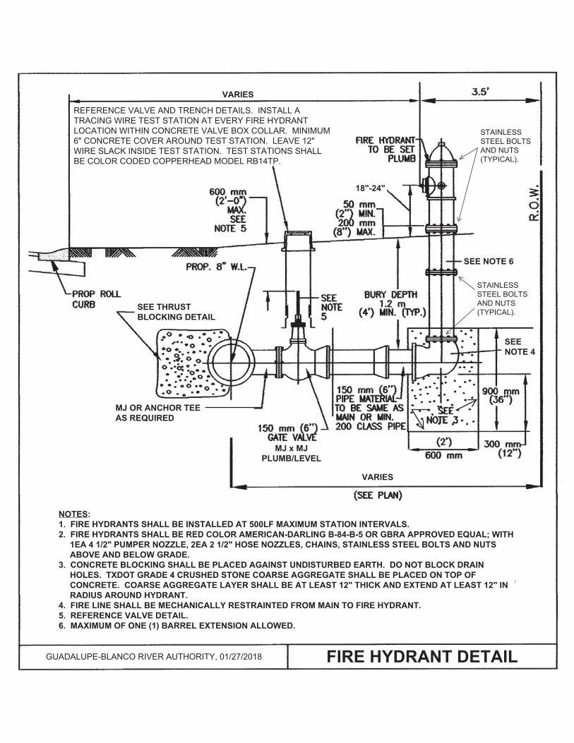
REFERENCE VALVE AND TRENCH DETAILS. INSTALL A TRACING WIRE TEST STATION AT EVERY FIRE HYDRANT LOCATION WITHIN CONCRETE VALVE BOX COLLAR. MINIMUM 6" CONCRETE COVER AROUND TEST STATION. LEAVE 12" WIRE SLACK INSIDE TEST STATION. TEST STATIONS SHALL BE COLOR CODED COPPERHEAD MODEL RB14TP.
GUADALUPE-BLANCO RIVER AUTHORITY, 01/27/2018
X18"-24"
CONCRETE BLOCKING SHALL BE PLACED AGAINST UNDISTURBED EARTH. DO NOT BLOCK DRAIN HOLES. SEWER GRAVEL SHALL BE PLACED ON TOP OF CONCRETE. GRAVEL LAYER SHALL BE AT LEAST 12" THICK AND EXTEND AT LEAST 12" IN RADIUS AROUND HYDRANT.
VARIES
VARIES
STAINLESS STEEL BOLTS AND NUTS (TYPICAL).
X
XXX
MJ x MJ PLUMB/LEVEL
FIRE LINE SHALL BE MECHANICALLY RESTRAINTED FROM MAIN TO FIRE HYDRANT.
MJ OR ANCHOR TEE AS REQUIRED
STAINLESS STEEL BOLTS AND NUTS (TYPICAL).
SEE NOTE 6
SEE NOTE 4
STAINLESS STEEL BOLTS AND NUTS (TYPICAL).
NOTES: 1. FIRE HYDRANTS SHALL BE INSTALLED AT 500LF MAXIMUM STATION INTERVALS. 2. FIRE HYDRANTS SHALL BE RED COLOR AMERICAN-DARLING B-84-B-5 OR GBRA APPROVED EQUAL; WITH XX1EA 4 1/2" PUMPER NOZZLE, 2EA 2 1/2" HOSE NOZZLES, CHAINS, STAINLESS STEEL BOLTS AND NUTS XXABOVE AND BELOW GRADE. 3. CONCRETE BLOCKING SHALL BE PLACED AGAINST UNDISTURBED EARTH. DO NOT BLOCK DRAIN XXHOLES. TXDOT GRADE 4 CRUSHED STONE COARSE AGGREGATE SHALL BE PLACED ON TOP OF XXCONCRETE. COARSE AGGREGATE LAYER SHALL BE AT LEAST 12" THICK AND EXTEND AT LEAST 12" IN XXRADIUS AROUND HYDRANT. 4. FIRE LINE SHALL BE MECHANICALLY RESTRAINTED FROM MAIN TO FIRE HYDRANT. 5. REFERENCE VALVE DETAIL. 6. MAXIMUM OF ONE (1) BARREL EXTENSION ALLOWED.
SEE NOTE 6
SEE THRUST BLOCKING DETAIL
FIRE HYDRANT DETAIL
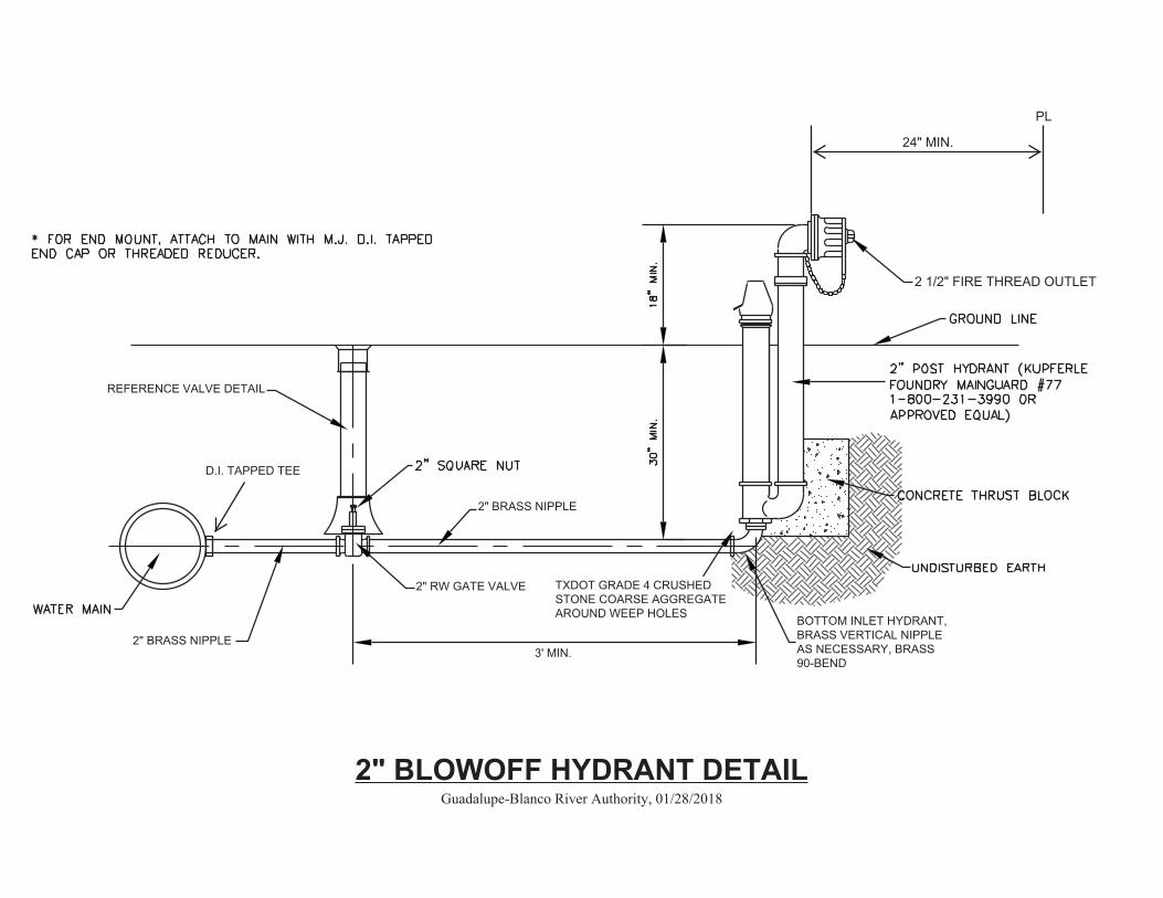
2" BRASS NIPPLE
BOTTOM INLET HYDRANT, BRASS VERTICAL NIPPLE AS NECESSARY, BRASS 90-BEND
X 2 1/2" FIRE THREAD OUTLET
REFERENCE VALVE DETAIL
24" MIN.
PL
2" RW GATE VALVE
3' MIN3' MIN
3' MIN.
D.I. TAPPED TEE
2" BRASS NIPPLE
TXDOT GRADE 4 CRUSHED STONE COARSE AGGREGATE AROUND WEEP HOLES
3' MIN.
2" BLOWOFF HYDRANT DETAIL Guadalupe-Blanco River Authority, 01/28/2018
3' MIN.
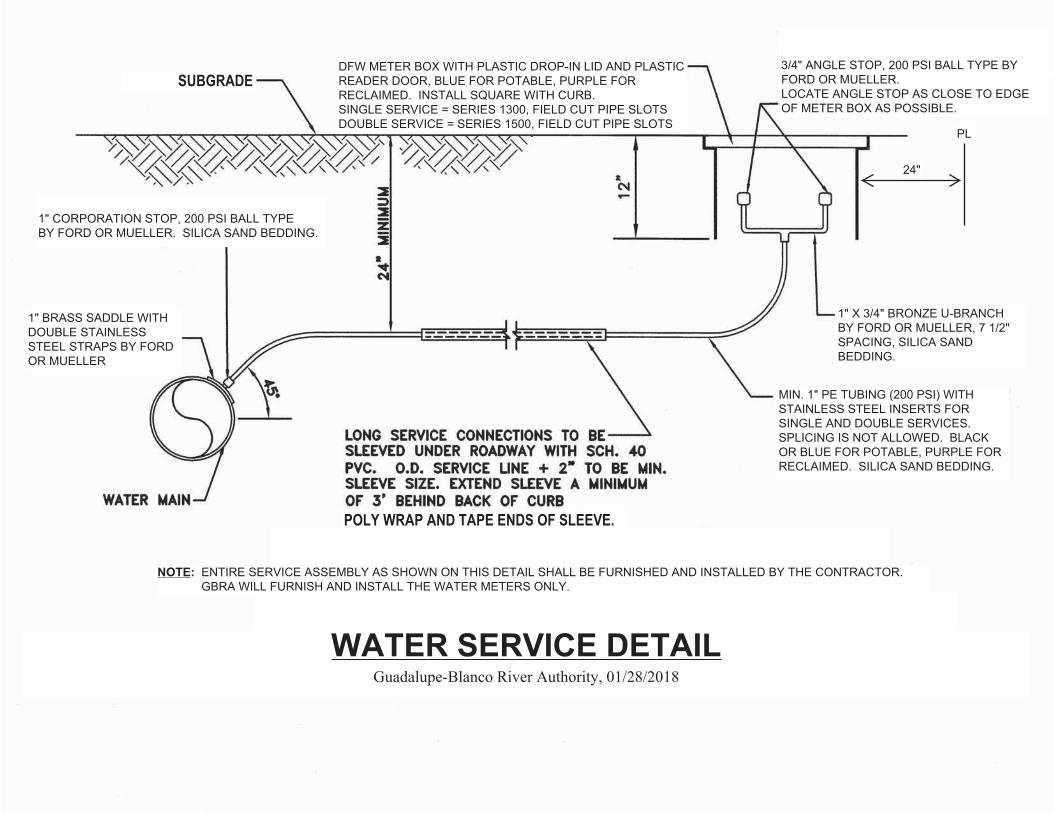
MIN. 1" PE TUBING (200 PSI) WITH STAINLESS STEEL INSERTS FOR SINGLE AND DOUBLE SERVICES. SPLICING IS NOT ALLOWED. BLACK OR BLUE FOR POTABLE, PURPLE FOR RECLAIMED. SILICA SAND BEDDING.
1" X 3/4" BRONZE U-BRANCH BY FORD OR MUELLER, 7 1/2" SPACING, SILICA SAND BEDDING.
X X 3/4" ANGLE STOP, 200 PSI BALL TYPE BY FORD OR MUELLER. LOCATE ANGLE STOP AS CLOSE TO EDGE OF METER BOX AS POSSIBLE.
DFW METER BOX WITH PLASTIC DROP-IN LID AND PLASTIC READER DOOR, BLUE FOR POTABLE, PURPLE FOR RECLAIMED. INSTALL SQUARE WITH CURB. SINGLE SERVICE = SERIES 1300, FIELD CUT PIPE SLOTS DOUBLE SERVICE = SERIES 1500, FIELD CUT PIPE SLOTS
X 1" CORPORATION STOP, 200 PSI BALL TYPE BY FORD OR MUELLER. SILICA SAND BEDDING.
1" BRASS SADDLE WITH DOUBLE STAINLESS STEEL STRAPS BY FORD OR MUELLER
1" PE TUBING WITH STAINLESS SPLICING IS NOT ALLOWED.
24"
PL
POLY WRAP AND TAPE ENDS OF SLEEVE.
X
SUBGRADE
SUBGRADE
NOTE: ENTIRE SERVICE ASSEMBLY AS SHOWN ON THIS DETAIL SHALL BE FURNISHED AND INSTALLED BY THE CONTRACTOR. NOTE: GBRA WILL FURNISH AND INSTALL THE WATER METERS ONLY.
WATER SERVICE DETAIL Guadalupe-Blanco River Authority, 01/28/2018

2" AIR RELEASE VALVE A.R.I. MODEL D-040
2" angle valve, or straight valve as necessary, with pipe thread outlet and 304SS bolts/nuts, 200 psi ball type by Ford or Mueller, install with operator handle on top
NO. 2 C.I. RECTANGULAR METER BOX (2 REQ'D), LID WITH BRACING AND DROP HANDLE, INSTALL SQUARE WITH CURB
2" PE TUBING WITH STAINLESS STEEL INSERTS (200 PSI) AND SILICA SAND BEDDING
brass tapping saddle with double stainless steel straps by Ford or Mueller
X 1 1/2" SCH 80 PVC PIPE
X1 1/2" SCH 80 PVC PIPE
1 1/2" Sch 80 PVC elbow
1 1/2" Sch 80 PVC elbow
3" SCH 40 STEEL PIPE WITH WELDED CAP (REF. PAINTING NOTES)
Install valve marker 2ft from property line
x
x
x
x 18"
2" Sch 80 PVC elbow w/brick
3"x8"x2" BRICK SUPPORT FOR METER BOX (APPROX. 11 REQ'D)
2" Sch 80 PVC nippleSILICA SAND BEDDING
2" corporation stop, 200 psi ball type by Ford or Mueller
1'-0"1'-0"
12" min
Galvanized Vent Cap, Clay and Bailey Mfg. Co. #401, or approved equal
NOTE: PVC MALE ADAPTERS ARE NOT ALLOWED.
VARIES
1 1/2" SCH 80 PVC UNION
PL
(DISTRIBUTION)AIR RELEASE VALVE FOR WATER DISTRIBUTION MAIN
Guadalupe-Blanco River Authority, 01/28/2018

Guadalupe-BlancoRiver Authority
C. LEWIS AUG. 31, 2017
x x
LOCATE AS DIRECTEDBY GBRA INSPECTOR
MAIN
WELDED CAPNOTES:1) VALVE MARKERS ARE REQUIRED FORALL BURIED VALVES IN UNPAVED AREAS.
2) VALVE MARKERS SHALL BE PAINTED 3" SCH 40STEEL PIPE (REFERENCE PAINTING NOTES). x
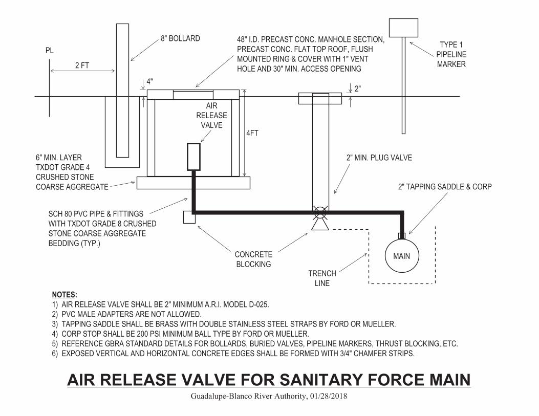
2" TAPPING SADDLE & CORP
CONCRETE BLOCKING
2" MIN. PLUG VALVE
PL8" BOLLARD
2 FT
TYPE 1 PIPELINE MARKER
AIR RELEASE
VALVE
SCH 80 PVC PIPE & FITTINGS WITH TXDOT GRADE 8 CRUSHED STONE COARSE AGGREGATE BEDDING (TYP.)
6" MIN. LAYER TXDOT GRADE 4 CRUSHED STONE COARSE AGGREGATE
48" I.D. PRECAST CONC. MANHOLE SECTION, PRECAST CONC. FLAT TOP ROOF, FLUSH MOUNTED RING & COVER WITH 1" VENT HOLE AND 30" MIN. ACCESS OPENING
4FT
NOTES: 1) AIR RELEASE VALVE SHALL BE 2" MINIMUM A.R.I. MODEL D-025. 2) PVC MALE ADAPTERS ARE NOT ALLOWED. 3) TAPPING SADDLE SHALL BE BRASS WITH DOUBLE STAINLESS STEEL STRAPS BY FORD OR MUELLER. 4) CORP STOP SHALL BE 200 PSI MINIMUM BALL TYPE BY FORD OR MUELLER. 5) REFERENCE GBRA STANDARD DETAILS FOR BOLLARDS, BURIED VALVES, PIPELINE MARKERS, THRUST BLOCKING, ETC. 6) EXPOSED VERTICAL AND HORIZONTAL CONCRETE EDGES SHALL BE FORMED WITH 3/4" CHAMFER STRIPS.
MAIN
TRENCH LINE
2"4"
AIR RELEASE VALVE FOR SANITARY FORCE MAIN Guadalupe-Blanco River Authority, 01/28/2018
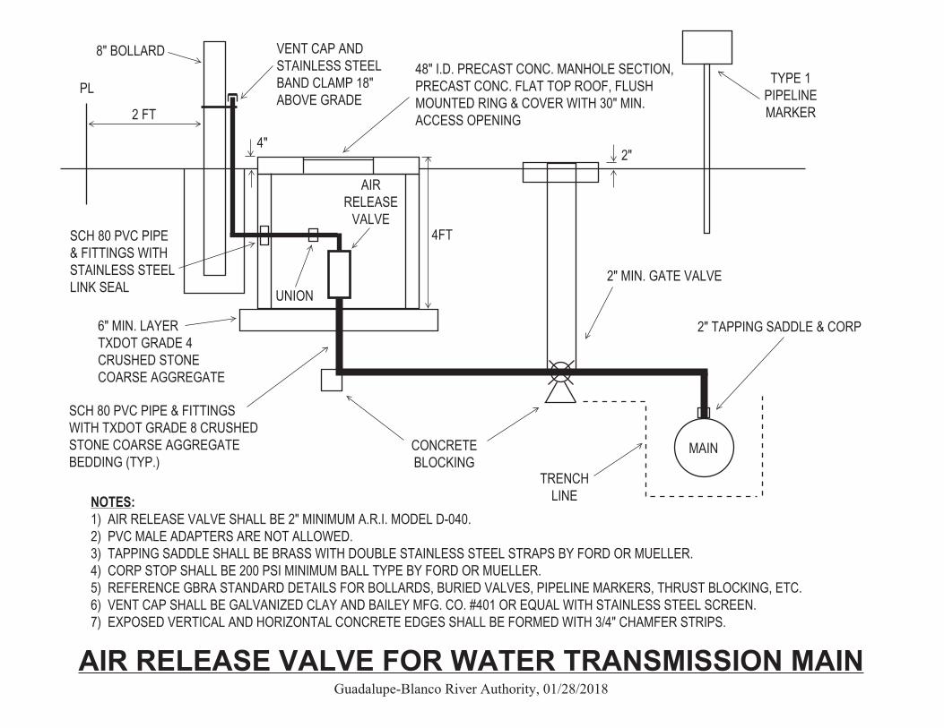
2" TAPPING SADDLE & CORP
CONCRETE BLOCKING
2" MIN. GATE VALVE
PL
8" BOLLARD
2 FT
TYPE 1 PIPELINE MARKER
AIR RELEASE
VALVE
48" I.D. PRECAST CONC. MANHOLE SECTION, PRECAST CONC. FLAT TOP ROOF, FLUSH MOUNTED RING & COVER WITH 30" MIN. ACCESS OPENING
NOTES: 1) AIR RELEASE VALVE SHALL BE 2" MINIMUM A.R.I. MODEL D-040. 2) PVC MALE ADAPTERS ARE NOT ALLOWED. 3) TAPPING SADDLE SHALL BE BRASS WITH DOUBLE STAINLESS STEEL STRAPS BY FORD OR MUELLER. 4) CORP STOP SHALL BE 200 PSI MINIMUM BALL TYPE BY FORD OR MUELLER. 5) REFERENCE GBRA STANDARD DETAILS FOR BOLLARDS, BURIED VALVES, PIPELINE MARKERS, THRUST BLOCKING, ETC. 6) VENT CAP SHALL BE GALVANIZED CLAY AND BAILEY MFG. CO. #401 OR EQUAL WITH STAINLESS STEEL SCREEN. 7) EXPOSED VERTICAL AND HORIZONTAL CONCRETE EDGES SHALL BE FORMED WITH 3/4" CHAMFER STRIPS.
MAIN
TRENCH LINE
2"4"
VENT CAP AND STAINLESS STEEL BAND CLAMP 18" ABOVE GRADE
SCH 80 PVC PIPE & FITTINGS WITH STAINLESS STEEL LINK SEAL UNION
4FT
AIR RELEASE VALVE FOR WATER TRANSMISSION MAIN Guadalupe-Blanco River Authority, 01/28/2018
SCH 80 PVC PIPE & FITTINGS WITH TXDOT GRADE 8 CRUSHED STONE COARSE AGGREGATE BEDDING (TYP.)
6" MIN. LAYER TXDOT GRADE 4 CRUSHED STONE COARSE AGGREGATE
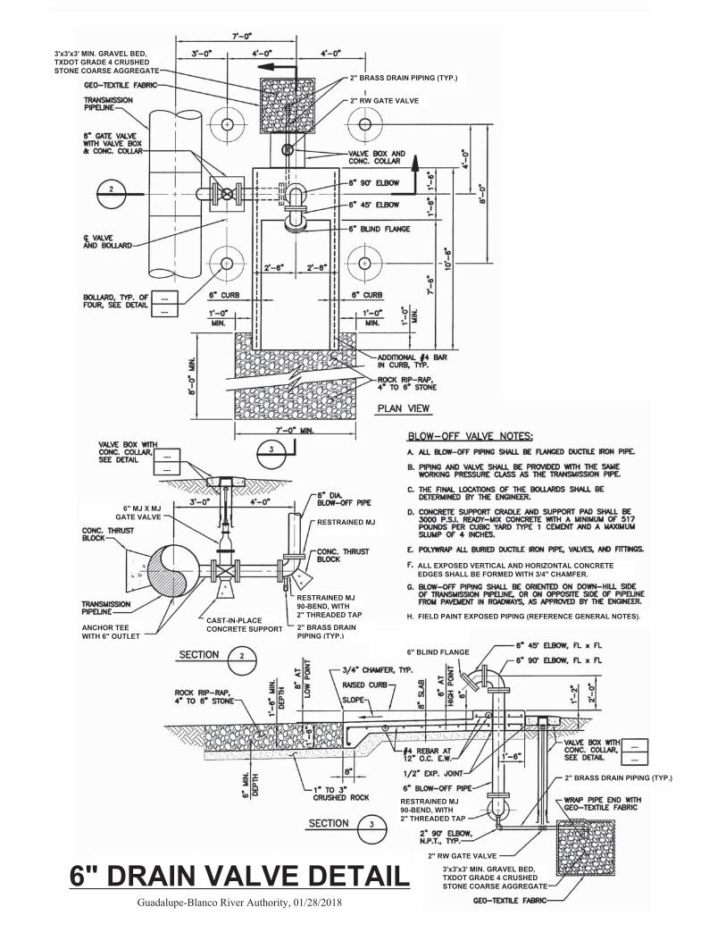
ALL EXPOSED VERTICAL AND HORIZONTAL CONCRETE EDGES SHALL BE FORMED WITH 3/4" CHAMFER.
XX
X
X
X
H. FIELD PAINT EXPOSED PIPING (REFERENCE GENERAL NOTES).
2" RW GATE VALVE
2" BRASS DRAIN PIPING (TYP.)
(FOR MAINS 8" AND LARGER)
RESTRAINED MJ
RESTRAINED MJ 90-BEND, WITH 2" THREADED TAP
ANCHOR TEE WITH 6" OUTLET
6" MJ X MJGATE VALVE
RESTRAINED MJ 90-BEND, WITH 2" THREADED TAP
2" RW GATE VALVE
2" BRASS DRAIN PIPING (TYP.)
2" BRASS DRAIN PIPING (TYP.)
.
.
. 6" BLIND FLANGE
---
---
---
---
---
---
CAST-IN-PLACE CONCRETE SUPPORT
3'x3'x3' MIN. GRAVEL BED, TXDOT GRADE 4 CRUSHED STONE COARSE AGGREGATE
3'x3'x3' MIN. GRAVEL BED, TXDOT GRADE 4 CRUSHED STONE COARSE AGGREGATE
6" DRAIN VALVE DETAIL Guadalupe-Blanco River Authority, 01/28/2018
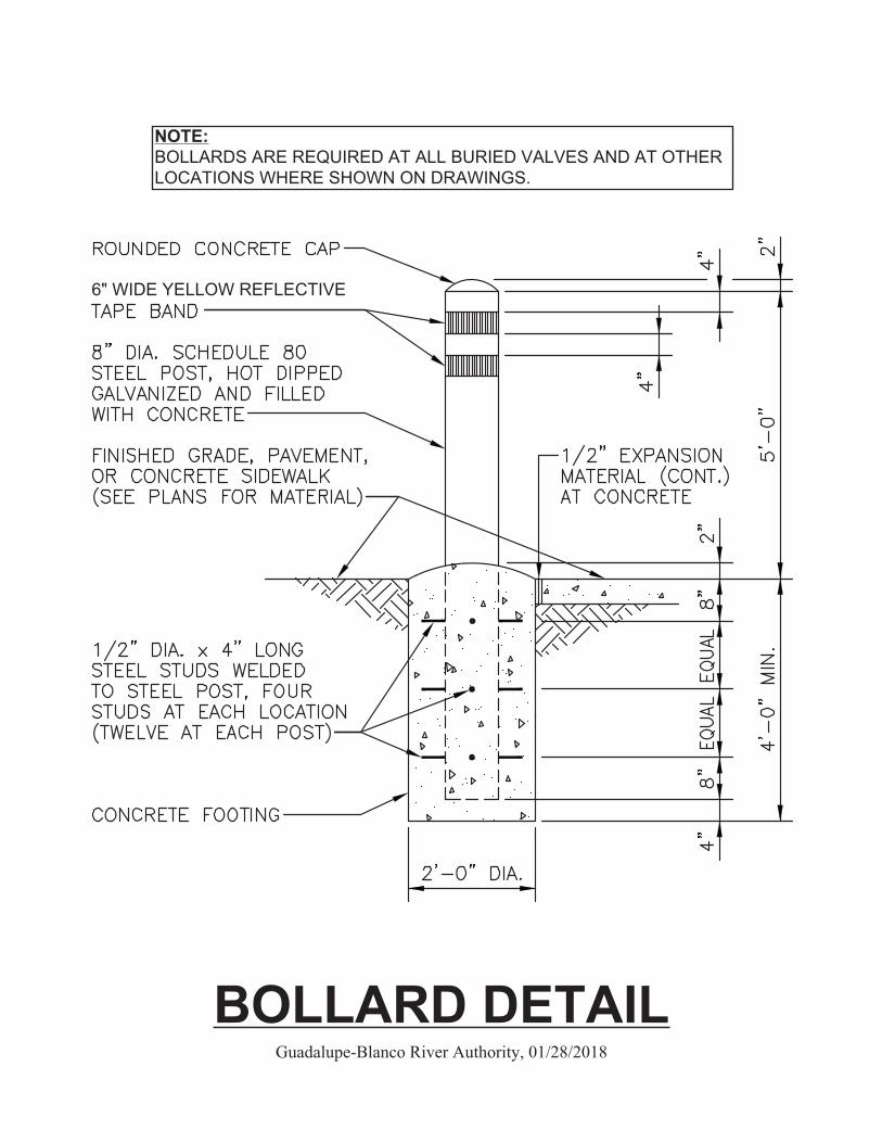
NOTE: BOLLARDS ARE REQUIRED AT ALL BURIED VALVES AND AT OTHER LOCATIONS WHERE SHOWN ON DRAWINGS.
6" WIDE YELLOW REFLECTIVE
XX
X BOLLARD DETAIL
Guadalupe-Blanco River Authority, 01/28/2018
STANDARD NOTES AND DETAILSMECHANICAL
BURIED PIPING DETAILS
TYPE 2 WATERLINE MARKER DETAIL
TYPE 2 WATERLINE MARKER DETAIL
TYPE 2 WATERLINE MARKER DETAIL
CALL 800-413-4130CALL 800-413-4130
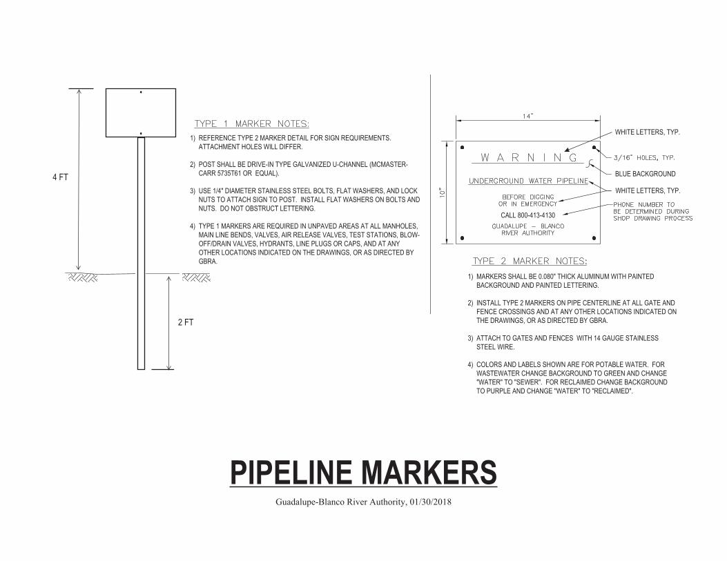
X PIPELINE MARKERS
Guadalupe-Blanco River Authority, 01/30/2018
1) REFERENCE TYPE 2 MARKER DETAIL FOR SIGN REQUIREMENTS. WJATTACHMENT HOLES WILL DIFFER. X 2) POST SHALL BE DRIVE-IN TYPE GALVANIZED U-CHANNEL (MCMASTER-WJCARR 5735T61 OR EQUAL). X 3) USE 1/4" DIAMETER STAINLESS STEEL BOLTS, FLAT WASHERS, AND LOCK WJNUTS TO ATTACH SIGN TO POST. INSTALL FLAT WASHERS ON BOLTS AND WJNUTS. DO NOT OBSTRUCT LETTERING. X 4) TYPE 1 MARKERS ARE REQUIRED IN UNPAVED AREAS AT ALL MANHOLES, WJMAIN LINE BENDS, VALVES, AIR RELEASE VALVES, TEST STATIONS, BLOW-WJOFF/DRAIN VALVES, HYDRANTS, LINE PLUGS OR CAPS, AND AT ANY WJOTHER LOCATIONS INDICATED ON THE DRAWINGS, OR AS DIRECTED BY WJGBRA.
TYPE 2 WATERLINE MARKER DETAIL
TYPE 2 WATERLINE MARKER DETAIL
TY
TY
4 FT
2 FT
BLUE BACKGROUND
WHITE LETTERS, TYP.
. 1) MARKERS SHALL BE 0.080" THICK ALUMINUM WITH PAINTED WJBACKGROUND AND PAINTED LETTERING. X 2) INSTALL TYPE 2 MARKERS ON PIPE CENTERLINE AT ALL GATE AND WJFENCE CROSSINGS AND AT ANY OTHER LOCATIONS INDICATED ON WJTHE DRAWINGS, OR AS DIRECTED BY GBRA. X 3) ATTACH TO GATES AND FENCES WITH 14 GAUGE STAINLESS WJSTEEL WIRE. X 4) COLORS AND LABELS SHOWN ARE FOR POTABLE WATER. FOR WJWASTEWATER CHANGE BACKGROUND TO GREEN AND CHANGE WJ"WATER" TO "SEWER". FOR RECLAIMED CHANGE BACKGROUND WJTO PURPLE AND CHANGE "WATER" TO "RECLAIMED".
WHITE LETTERS, TYP.

Guadalupe-BlancoRiver Authority
C. LEWIS
1%
Service Lateral 6" Dia. Min. SDR26
x
x
x
x xx
x
x
x
x
x
x 4' to 6'
Sewer Main SDR26
45-Bend SDR26
NOTES: 1) Install double services where indicated on design drawings. 2) Cleanout to be installed by customer plumber. 3) Pipe and fittings shall be gasketed. Tees and 90-bends are not allowed. 4) Pressure rated pipe and fittings shall be installed for sewer mains and laterals that cross water lines (use ASTM D2241 XXSDR26). Center both water and sewer pipe lengths at all crossings. Comply with TCEQ Rules. 5) Tapping saddles are not allowed.
x
Cap at Property Line or Across Dry
Utility Easement
Whichever is Further
JAN. 28, 2018
x x
x
x
x
4' to 6' Top of Pipe
Wye or Sanitary Tee, rotated to 10 o'clock or 2 o'clock, with 45-Bend (reference Typical Cleanout Detail)
LLATERAL DETAIL
Pipe Extension as Required
1% Minimum 4% Maximum
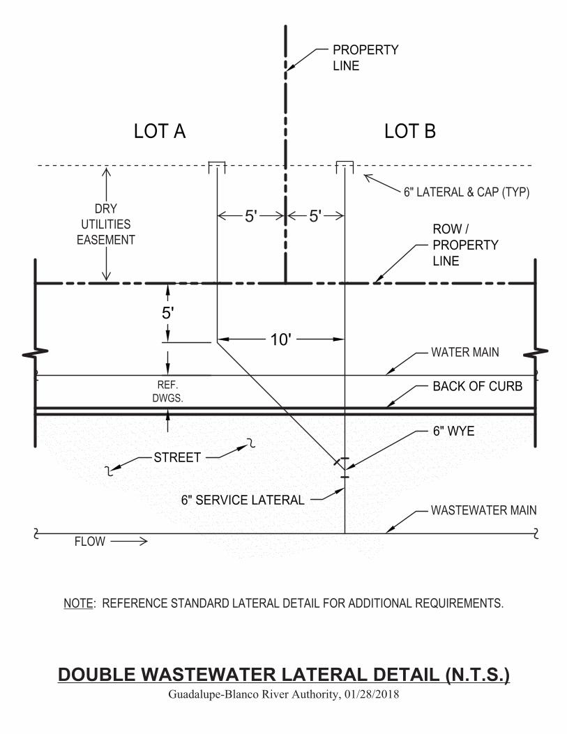
DOUBLE WASTEWATERSERVICE LATERAL
N.T.S.
10'5'
4'
X X
NOTE: REFERENCE STANDARD LATERAL DETAIL FOR ADDITIONAL REQUIREMENTS. X X X X
DOUBLE WASTEWATER LATERAL DETAIL (N.T.S.) Guadalupe-Blanco River Authority, 01/28/2018
WASTEWATER MAIN
WATER MAIN
REF. DWGS.
DRY UTILITIES
EASEMENT
6" LATERAL & CAP (TYP)
5' 5'
FLOW

CL CL
SAND EMBEDMENT
STREET
45° BEND
NO JOINTSALLOWEDIN VERTICALRISER
CONCRETE ENCASEMENTFOR STACK CONNECTION
TYP.
. ... . .
..
. . .. .
.... . ..
.
..
6"
SAND EMBEDMENT
45° BEND
TEE OR WYE ON MAIN
EACH STACK SHALL BESET IN SAND EMBEDMENT
PINNED OR SLEEVED ASNECESSARY TO SUPPORTRISER BEFORE & DURINGBACKFILL OPERATION
USE 2 - 45° BENDS
CLASS A CONCRETE
EARTH FILL
A
A
TRENCH
..
.
.....
..
. .
.
...
.
.
.
..
.. . . .
..
.
.
.
..
. . .
.
. . .
..
...
.
.
.
.
.
.
. .. . .
.
.
..
. ..
..
. .
.... .
..
.
..
. ...
. . ..
..
... .
.
-CL
SECTION A - A
4"MIN.
3"MIN.
BLOCK UP 3"AS NECESSARY
. . . ... .. .
. ... .
.. .
.. .
..
..
.. .
.
..
. .... . .
.. .
.
...
....
. ....
. . . . . . . ...
...... .
.. .
.. .
.. . .... .
..
....
.
CURB
MIN. SLOPE 1 % CL
CL
4' M
IN.
6' M
AX
.
5' M
IN. T
O B
E R
OU
TE
DT
O M
ISS
WA
TE
RM
AIN
VERIFY DEPTH TOENSURE ADEQUATESLOPE (1% MIN.) TOCUSTOMER
. .. ................
. . . ..
.. .
..
. .. .
. .... .. . .. . .... . . . . . . . . ......
PL
NOTE:
FOR DETAILS AT PROPERTYLINE, SEE STANDARD SERVICECONNECTION DETAIL.
DRAWING NO.SHEET:SCALE:
DRAWN BY:
APPROVED BY:
UPDATED:
STANDARD DRAWING:
NEW BRAUNFELS UTILITIESWATER SYSTEMS ENGINEERING
WYE OR SANITARY TEE
CONCRETE ENCASEMENT
SEWER GRAVEL
EACH STACK SHALL BE SET IN SEWER GRAVEL EMBEDMENT
TRENCH BACKFILL
XXXX
CAP AT PROPERTY LINE
S
S
SEWER
C. LEWIS
JAN. 28, 2018
GUADALUPE-BLANCO RIVER AUTHORITY
WASTEWATER LATERAL VERTICAL STACK DETAIL
SEWERSEWESEWE
6" MIN. SDR26
NOTES: 1) CONCRETE ENCASEMENT SHALL BE NNPLACED AGAINST UNDISTURBED EARTH NNTO INCLUDE WYE/TEE AND 45-BEND. 2) TAPPING SADDLES ARE NOT ALLOWED. 3) REFERENCE STANDARD LATERAL DETAIL NNFOR ADDITIONAL REQUIREMENTS.
X 6" MIN.
6" MIN. BLOCK UP AS NECESSARY
X X X SLOPE 1% MINIMUM 4% MAXIMUMU
ND
ER
WA
TER
MA
IN
12" M
IN. C
LEA
RA
NC
E
TXDOT GRADE 4 CRUSHED STONE COARSE AGGREGATE BEDDING
.12" MIN.
.
4' M
IN. T
O 6
' MA
X.
TOP
OF
PIP
E
CAP AT PROPERTY LINE OR ACROSS DRY
UTILITY EASEMENT
WHICHEVER IS FURTHER
Guadalupe-BlancoRiver Authority x
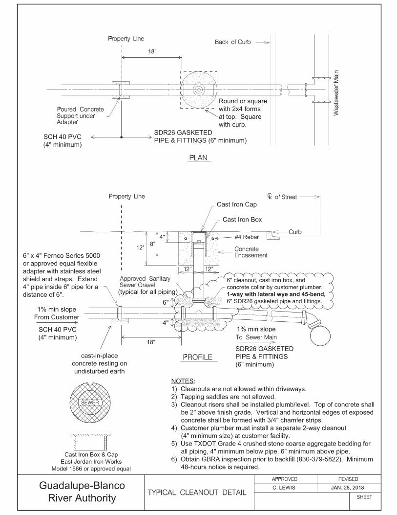
6" x 4" Fernco Series 5000or approved equal flexibleadapter with stainless steelshield and straps. Extend4" pipe inside 6" pipe for adistance of 6".
1% min slopeFrom Customer
SDR26 GASKETEDPIPE & FITTINGS(6" minimum)
NOTES:1) Cleanouts are not allowed within driveways.2) Tapping saddles are not allowed.3) Cleanout risers shall be installed plumb/level. Top of concrete shallxxxbe 2" above finish grade. Vertical and horizontal edges of exposedxxxconcrete shall be formed with 3/4" chamfer strips.4) Customer plumber must install a separate 2-way cleanoutxxx(4" minimum size) at customer facility.5) Use TXDOT Grade 4 crushed stone coarse aggregate bedding forxxxall piping, 4" minimum below pipe, 6" minimum above pipe.6) Obtain GBRA inspection prior to backfill (830-379-5822). Minimumxxx48-hours notice is required.
SCH 40 PVC(4" minimum)
1% min slope
Cast Iron Box
Cast Iron Box & CapEast Jordan Iron Works
Model 1566 or approved equal
Cast Iron Cap
SCH 40 PVC(4" minimum)
cast-in-placeconcrete resting onundisturbed earth
From Customer
#4 Rebar
C. LEWIS JAN. 28, 2018
x
6" cleanout, cast iron box, and concrete collar by customer plumber. 1-way with lateral wye and 45-bend, 6" SDR26 gasketed pipe and fittings.
8"12"
4"
(typical for all piping)6"
4"
SDR26 GASKETEDPIPE & FITTINGS (6" minimum)
Round or squarewith 2x4 formsat top. Squarewith curb.
x
x
x
x
xx
x 18"
x
18"

30" MINIMUM CLEAR ACCESS OPENING
PRECAST SECTIONSPER ASTM C-478
863mm (34")+/-12.5mm (1/2")
1.20m (48")INSIDE DIAMETER MINIMUM
RUBBER GASKETS
PIPE TO MANHOLE BOOTPSX DIRECT DRIVEOR APPROVED EQUAL.FILL WITH NON-SHRINKGROUT. PIPE TOPROJECT INSIDEMANHOLE 1" BEYONDINSIDE FACE OF WALL.
PIPE TO MANHOLE BOOTPSX DIRECT DRIVEOR APPROVED EQUAL.FILL WITH NON-SHRINKGROUT. PIPE TOPROJECT INSIDEMANHOLE 1" BEYONDINSIDE FACE OF WALL.
NON-SHRINK GROUTEXTERIOR JOINTS
INLET 0.10' MIN. ABOVE OUTLET
x"U" SHAPED INVERT.90-DEG MAXIMUM CHANGEIN FLOW DIRECTION.
x1. MANHOLE BASE SHALL BE BEDDED ON A 6" MINIMUM LAYER OF TXDOT GRADE 4 CRUSHED STONE COARSE AGGREGATE.XNBASE SHALL BE LEVEL/PLUMB PRIOR TO INSTALLING RISER SECTIONS.2. SAND BLAST AND LINE ALL INTERIOR SURFACES OF ALL MANHOLES (INCLUDING INVERTS) WITH SEWPERCOAT, REFRATTAXNHAC 100, OR APPROVED EQUAL CALCIUM ALUMINATE MATERIAL. PROPOSED SUBSTITUTES MUST BE EQUAL INXNCOMPOSITION AND MANUFACTURER WARRANTY. PRODUCT MUST BE INSTALLED BY A MANUFACTURER CERTIFIEDXNAPPLICATOR. MINIMUM 1/2" THICKNESS. SMOOTH TROWEL FINISH. SPRAY CURING COMPOUND.
NOTES:
xC. LEWIS
MAR. 29, 2017Guadalupe-BlancoRiver Authority
WASTEWATER MANHOLE ON PRECAST BASE
C. LEWISJAN. 28, 2018
CONCRETE INVERT SHAPEDBY CONTRACTOR
"U" SHAPEDINVERT MIN.3/4 LARGESTPIPE I.D.
12" MINIMUM THICKNESS OFCONCRETE FOUNDATION
TYPICAL 0-RING
PRECAST SECTIONPER ASTM C-478
PLACE 1st SECTIONIN FRESH CONCRETE
STANDARD NEOPRENEPIPE GASKET
A
A
34 1/2"±1/2"
48"INSIDE DIAMETER
CONCRETE, ITEM 403(3000 P.S.I.)
*ALL PVC PIPE SHALL BE REMOVED FROM INVERT
3" THROAT±1/2"
CLASS A
STANDARD RING AND32" COVER
18"
21" MAXCHIMNEY HEIGHT
DRAWING NO.SHEET:SCALE:
DRAWN BY:
APPROVED BY:
UPDATED:
STANDARD DRAWING:
NEW BRAUNFELS UTILITIESWATER SYSTEMS ENGINEERING
x
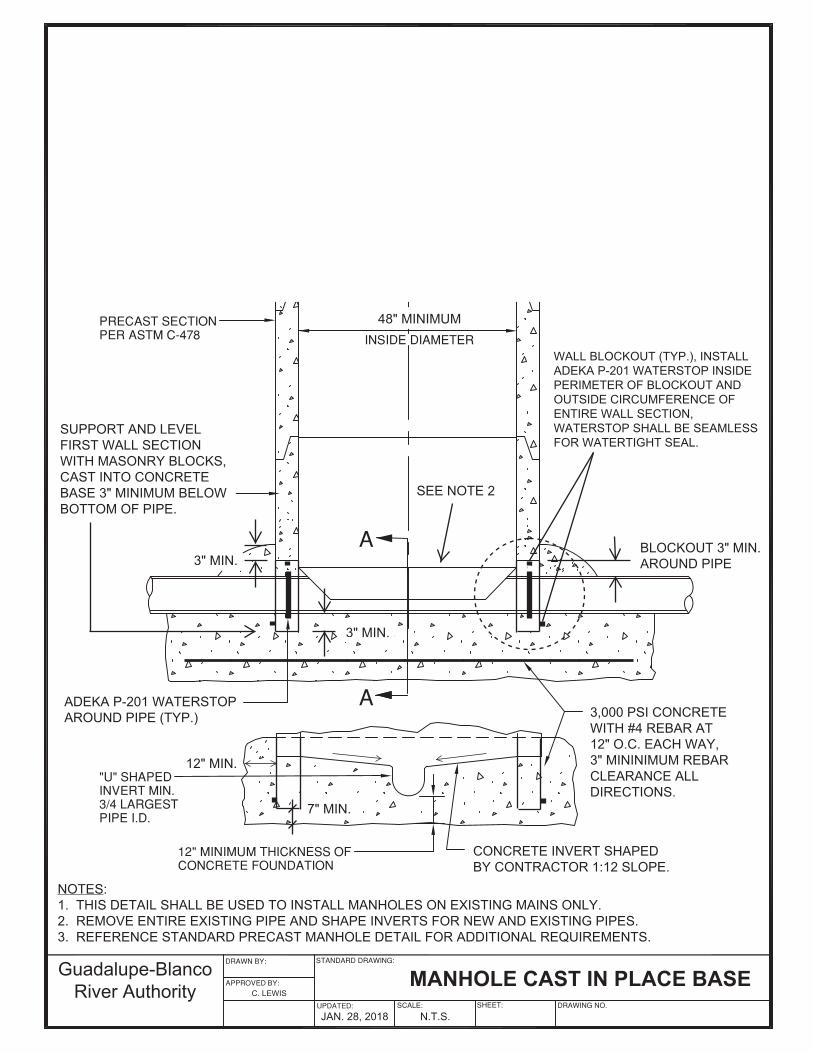
SUPPORT AND LEVELFIRST WALL SECTIONWITH MASONRY BLOCKS,CAST INTO CONCRETEBASE 3" MINIMUM BELOWBOTTOM OF PIPE.
x
ADEKA P-201 WATERSTOPAROUND PIPE (TYP.)
WALL BLOCKOUT (TYP.), INSTALLADEKA P-201 WATERSTOP INSIDEPERIMETER OF BLOCKOUT ANDOUTSIDE CIRCUMFERENCE OFENTIRE WALL SECTION,WATERSTOP SHALL BE SEAMLESSFOR WATERTIGHT SEAL.
3" MIN.
SEE NOTE 2
3,000 PSI CONCRETE WITH #4 REBAR AT 12" O.C. EACH WAY, 3" MININIMUM REBAR CLEARANCE ALL DIRECTIONS.
NOTES:1. THIS DETAIL SHALL BE USED TO INSTALL MANHOLES ON EXISTING MAINS ONLY.2. REMOVE ENTIRE EXISTING PIPE AND SHAPE INVERTS FOR NEW AND EXISTING PIPES.3. REFERENCE STANDARD PRECAST MANHOLE DETAIL FOR ADDITIONAL REQUIREMENTS.
Guadalupe-BlancoRiver Authority
xxJAN. 28, 2018
C. LEWIS
C. LEWIS MANHOLE CAST IN PLACE BASE
3" MIN.
12" MIN.
N.T.S.
CONCRETE INVERT SHAPED BY CONTRACTOR 1:12 SLOPE.
BLOCKOUT 3" MIN. AROUND PIPE
48" MINIMUM
7" MIN.
MANHOLE CAST IN PLACE BASE
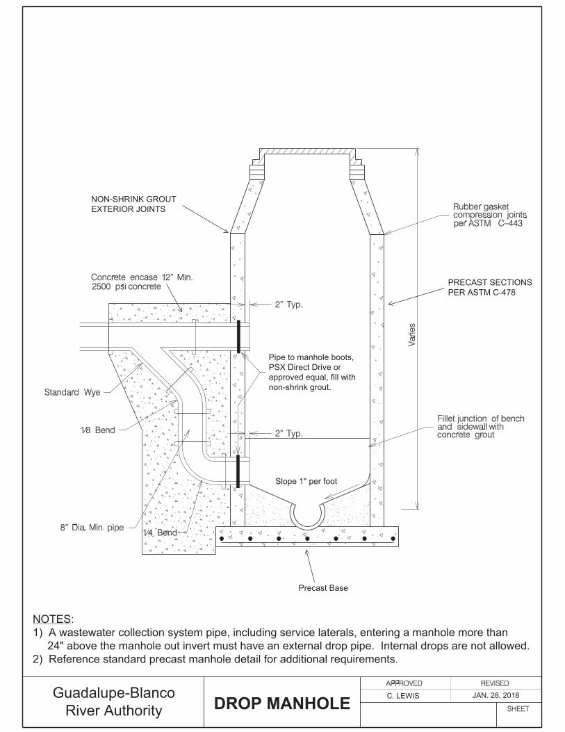
Pipe to manhole boots,PSX Direct Drive orapproved equal, fill withnon-shrink grout.
x x xx
Slope 1" per foot
Guadalupe-BlancoRiver Authority x x
C. LEWIS JAN. 28, 2018
NOTES:1) A wastewater collection system pipe, including service laterals, entering a manhole more thanXX24" above the manhole out invert must have an external drop pipe. Internal drops are not allowed.2) Reference standard precast manhole detail for additional requirements.
Precast Base
DROP MANHOLE
NON-SHRINK GROUTEXTERIOR JOINTS
PRECAST SECTIONSPER ASTM C-478
Guadalupe-BlancoRiver Authority
xx x
Ring O.D.
5'-6"
3,000 psi
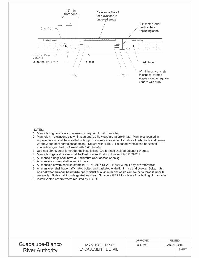
12" min from cone
x
6" minX #4 Rebar
9" minimum concrete thickness, formed edges round or square, square with curb
NOTES: 1) Manhole ring concrete encasement is required for all manholes. 2) Manhole rim elevations shown in plan and profile views are approximate. Manholes located in xxxunpaved areas shall be installed with top of concrete encasement 2" above finish grade and covers xxx2" above top of concrete encasement. Square with curb. All exposed vertical and horizontal xxxconcrete edges shall be formed with 3/4" chamfer. 3) Use non-shrink grout for grade ring installation. Grade rings shall be precast concrete. 4) Manhole rings and covers shall be East Jordan Product Number 42432109W01. 5) All manhole rings shall have 30" minimum clear access opening. 6) All manhole covers shall have pick bars. 7) All manhole covers shall be stamped "SANITARY SEWER" only without any city references. 8) All manholes shall have traffic rated bolted and gasketed watertight rings and covers. Bolts, nuts, xxxand flat washers shall be 316SS, apply nickel or aluminum anti-seize compound to threads prior to xxxassembly. Bolts shall include gasket washers. Schedule GBRA to witness final bolting of manholes. 9) Install vented covers where required by TCEQ.
x
x New PavingExisting Paving
x
C. LEWIS JAN. 28, 2018
21" max interior vertical face, including cone
RingO.D
XX
Reference Note 2 for elevations in unpaved areas
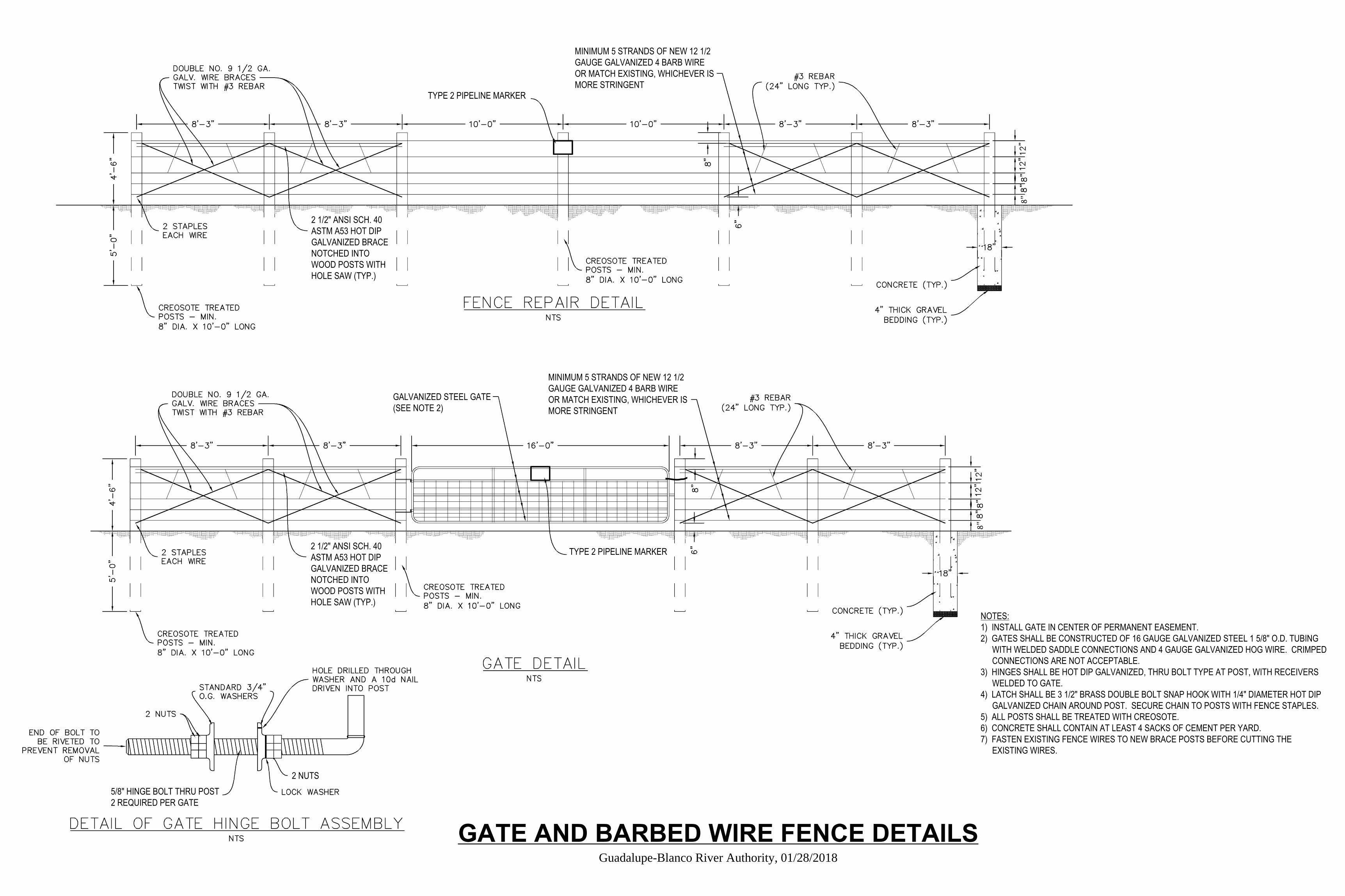
NOTES: 1) INSTALL GATE IN CENTER OF PERMANENT EASEMENT. 2) GATES SHALL BE CONSTRUCTED OF 16 GAUGE GALVANIZED STEEL 1 5/8" O.D. TUBING COWITH WELDED SADDLE CONNECTIONS AND 4 GAUGE GALVANIZED HOG WIRE. CRIMPED COCONNECTIONS ARE NOT ACCEPTABLE. 3) HINGES SHALL BE HOT DIP GALVANIZED, THRU BOLT TYPE AT POST, WITH RECEIVERS COWELDED TO GATE. 4) LATCH SHALL BE 3 1/2" BRASS DOUBLE BOLT SNAP HOOK WITH 1/4" DIAMETER HOT DIP COGALVANIZED CHAIN AROUND POST. SECURE CHAIN TO POSTS WITH FENCE STAPLES. 5) ALL POSTS SHALL BE TREATED WITH CREOSOTE. 6) CONCRETE SHALL CONTAIN AT LEAST 4 SACKS OF CEMENT PER YARD. 7) FASTEN EXISTING FENCE WIRES TO NEW BRACE POSTS BEFORE CUTTING THE COEXISTING WIRES.
2 NUTS5/8" HINGE BOLT THRU POST 2 REQUIRED PER GATE
2 1/2" ANSI SCH. 40 ASTM A53 HOT DIP GALVANIZED BRACE NOTCHED INTO WOOD POSTS WITH HOLE SAW (TYP.)
2 1/2" ANSI SCH. 40 ASTM A53 HOT DIP GALVANIZED BRACE NOTCHED INTO WOOD POSTS WITH HOLE SAW (TYP.)
TYPE 2 PIPELINE MARKER
TYPE 2 PIPELINE MARKER
G GALVANIZED STEEL GATE (SEE NOTE 2)
MINIMUM 5 STRANDS OF NEW 12 1/2 GAUGE GALVANIZED 4 BARB WIRE OR MATCH EXISTING, WHICHEVER IS MORE STRINGENT
MINIMUM 5 STRANDS OF NEW 12 1/2 GAUGE GALVANIZED 4 BARB WIRE OR MATCH EXISTING, WHICHEVER IS MORE STRINGENT
2 NUTS
2 NUTS
2 NUTS
8"
8"
GATE AND BARBED WIRE FENCE DETAILS Guadalupe-Blanco River Authority, 01/28/2018


