STANDING WAKEFIELD ACCELERATOR BASED ON PERIODIC DIELECTRIC STRUCTURES Xuan Wei ∗ , D. Stratakis, G. Andonian, J. B. Rosenzweig, UCLA, Los Angeles, CA, 90095, USA Abstract In recent years dielectric wakefield accelerators (DWA) have attracted significant attention for applications in high energy physics and THz radiation sources. However, one needs sufficiently short driving bunches in order to take advantage of the DWA’s scaling characteristics to achieve high gradient and high frequency accelerating fields. Since a single large charge (Q) driving bunch is difficult to be compressed to the needed rms bunch length (σ z ), a driving bunch train with smaller Q and small emittance, should be used instead for the DWA. In view of this senario, the group velocity of the excited wakefields needs to be decreased to nearly zero, so the electromagnetic energy does not vacate the structure during the bunch train. In this paper we pro- pose a standing wakefield accelerator based on periodic di- electric structures, and address the difference between the proposed structure and the conventional DWA. INTRODUCTION Acceleration of electrons in wakefields set up by a train of drive bunches in a dielectric structure has shown promise as the basis for a linear accelerator in which large accel- erating gradients can be achieved [1-2]. In a conventional DWA, an ultrarelativistic electron bunch travels through the vacuum channel surrounded by an uniform dielectric layer. The electric field of the bunch interacts with the dielec- tric material to excite Cerenkov wakefields in the structure, shown in Fig. 1. By placing a Gaussian pillbox just inside Figure 1: Illustration of a cylindrical DWA. A “driving” bunch excites the wakefields in the dielectric layer, while a following “witness” bunch (not shown) would be acceler- ated by the wakefields (color bands). the dielectric layer and enclosing the drive bunch, one can approximate the decelerating field by [3] E z,dec ≈ eN b πa 0 a + 8π r−1 r σ z (1) ∗ [email protected]where a is the inner radius of the dielectric layer, and r is the relative dielectric constant. From Eq. (1) we see that for very small σ z the decelerating field scales approxi- mately with 1/a 2 . This is a powerful scaling characteristic that enables DWA to achieve high gradient fields (GV/m). Resonant excitation of coherent Cerenkov wakefields [4] and breakdown limits [5] in a uniform DWA has been ex- plored experimentally at BNL and UCLA respectively. The eigenmodes excited by an on-axis driving bunch are azu- muthally symmetric TM 0n modes. The resonant frequen- cies at which the electron bunch excites are found by solv- ing dispersion relation of the electron bunch, given by ω = v b k (2) along with the transcendental dispersion relation for the structure, namely [6] I 1 (k n a) I 0 (k n a) = r k n κ n J 0 (κ n b)Y 1 (κ n a) − Y 0 (κ n b)J 1 (κ n a) J 0 (κ n b)Y 0 (κ n a) − Y 0 (κ n b)J 0 (κ n a) (3) where k n and κ n are the radial wave numbers in the beam channel and dielectric regions, respectively. The group ve- locity (v g ) of the wakefield is much slower than the phase velocity (v φ = v b ≈ c), and it can be computed numeri- cally from v g = P U em (4) where P is the total power and U em is the total electro- magnetic field energy per unit length. We can visually compare v g and v φ of the wakefields from the dispersion relation, shown in Fig. 2. The group velocities of the res- 0 2 4 6 8 10 0 1 2 3 4 k 10 5 m 1 f 10 12 s 1 Dispersion Relation for Uniform DWA Figure 2: Eq. (2) and the first three modes ( TM 01 , TM 02 , and TM 03 ) from Eq. (3) are plotted for an uniform DWA. onant modes are the slopes (2π∂f/∂k) of the dispersion curve at the intersecting points. Fig. 3 illustrates the role of MOP011 Proceedings of 2011 Particle Accelerator Conference, New York, NY, USA 124 Copyright c ○ 2011 by PAC’11 OC/IEEE — cc Creative Commons Attribution 3.0 (CC BY 3.0) Advanced Concepts and Future Directions Accel/Storage Rings 08: Linear Accelerators
Transcript
STANDING WAKEFIELD ACCELERATOR BASED ON PERIODICDIELECTRIC STRUCTURES
Xuan Wei∗, D. Stratakis, G. Andonian, J. B. Rosenzweig, UCLA, Los Angeles, CA, 90095, USA
Abstract
In recent years dielectric wakefield accelerators (DWA)have attracted significant attention for applications in highenergy physics and THz radiation sources. However, oneneeds sufficiently short driving bunches in order to takeadvantage of the DWA’s scaling characteristics to achievehigh gradient and high frequency accelerating fields. Sincea single large charge (Q) driving bunch is difficult to becompressed to the needed rms bunch length (σz), a drivingbunch train with smaller Q and small emittance, should beused instead for the DWA. In view of this senario, the groupvelocity of the excited wakefields needs to be decreased tonearly zero, so the electromagnetic energy does not vacatethe structure during the bunch train. In this paper we pro-pose a standing wakefield accelerator based on periodic di-electric structures, and address the difference between theproposed structure and the conventional DWA.
INTRODUCTION
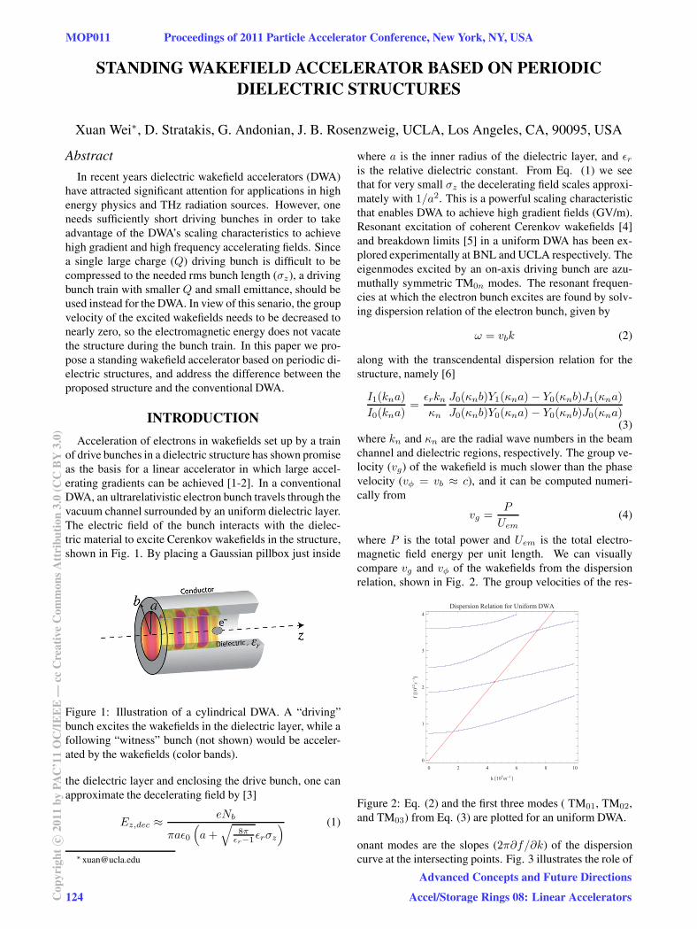
Acceleration of electrons in wakefields set up by a trainof drive bunches in a dielectric structure has shown promiseas the basis for a linear accelerator in which large accel-erating gradients can be achieved [1-2]. In a conventionalDWA, an ultrarelativistic electron bunch travels through thevacuum channel surrounded by an uniform dielectric layer.The electric field of the bunch interacts with the dielec-tric material to excite Cerenkov wakefields in the structure,shown in Fig. 1. By placing a Gaussian pillbox just inside
Figure 1: Illustration of a cylindrical DWA. A “driving”bunch excites the wakefields in the dielectric layer, while afollowing “witness” bunch (not shown) would be acceler-ated by the wakefields (color bands).
the dielectric layer and enclosing the drive bunch, one canapproximate the decelerating field by [3]
where a is the inner radius of the dielectric layer, and εris the relative dielectric constant. From Eq. (1) we seethat for very small σz the decelerating field scales approxi-mately with 1/a2. This is a powerful scaling characteristicthat enables DWA to achieve high gradient fields (GV/m).Resonant excitation of coherent Cerenkov wakefields [4]and breakdown limits [5] in a uniform DWA has been ex-plored experimentally at BNL and UCLA respectively. Theeigenmodes excited by an on-axis driving bunch are azu-muthally symmetric TM0n modes. The resonant frequen-cies at which the electron bunch excites are found by solv-ing dispersion relation of the electron bunch, given by
ω = vbk (2)
along with the transcendental dispersion relation for thestructure, namely [6]
I1(kna)
I0(kna)=
εrknκn
J0(κnb)Y1(κna)− Y0(κnb)J1(κna)
J0(κnb)Y0(κna)− Y0(κnb)J0(κna)(3)
where kn and κn are the radial wave numbers in the beamchannel and dielectric regions, respectively. The group ve-locity (vg) of the wakefield is much slower than the phasevelocity (vφ = vb ≈ c), and it can be computed numeri-cally from
vg =P
Uem(4)
where P is the total power and Uem is the total electro-magnetic field energy per unit length. We can visuallycompare vg and vφ of the wakefields from the dispersionrelation, shown in Fig. 2. The group velocities of the res-
0 2 4 6 8 100
1
2
3
4
k �105m�1�
f�1012 s�1 �
Dispersion Relation for Uniform DWA
Figure 2: Eq. (2) and the first three modes ( TM01, TM02,and TM03) from Eq. (3) are plotted for an uniform DWA.
onant modes are the slopes (2π∂f/∂k) of the dispersioncurve at the intersecting points. Fig. 3 illustrates the role of
MOP011 Proceedings of 2011 Particle Accelerator Conference, New York, NY, USA
124Cop
yrig
htc ○
2011
byPA
C’1
1O
C/I
EE
E—
ccC
reat
ive
Com
mon
sAtt
ribu
tion
3.0
(CC
BY
3.0)
Advanced Concepts and Future Directions
Accel/Storage Rings 08: Linear Accelerators
group velocity in the structure. For a given time t, the elec-tron bunch has travelled a distance vbt, exciting Cerenkovwakefield behind it. The total volume behind the drivingbunch is not completely filled with radiation because dur-ing the same time the wakefield has travelled a distancevgt. In the limit of zero group velocity, both region 1 and2 will be filled with radiation. For nonzero vg , region 1is excluded, leaving only region 2 occupied by wakefields[7]. The primary motivation of our work is to investigate
Figure 3: Illustration of the group velocity for a Cerenkovwakefield pulse excited by a relativistic electron bunch.
the possibility of designing a zero group velocity DWA byintroducing a periodicity in the dielectric function.
THEORY AND SIMULATION
In order to completely fill the volume behind the drivingbunch with wakefields, we introduce a longitudinal period-icity in the dielectric material, namly εr(z) = εr(z + d),where d is the period. The wakefield will undergo mul-tiple reflections and thereby lowering the group velocity.To treat this problem analytically, we need to solve theMaxwell equation in inhomogeneous media given by [8]
[∇2 + εrk2]E +∇ (E · ∇ ln εr) = 0 (5)
the solution to Eq. (5) consists of an infinite sum of spatialharmonics, namely [9]
Ez =∞∑
n=−∞En(y)e
i(kz+nK)z (6)
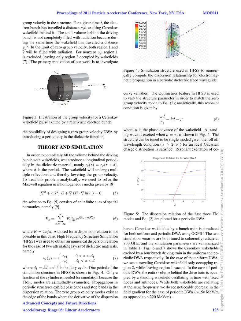
where K = 2π/d. A closed form dispersion relation is notpossible in this case. High Frequency Structure Simulation(HFSS) was used to obtain an numerical dispersion relationfor the case of two alternating layers of dielectric materials,namely
εr(z) =
{εr1 0 < z < d1εr2 d1 < z < d
(7)
where d1 = δd, and δ is the duty cycle. One period of thesimulation structure in HFSS is shown in Fig. 4. Only afraction of the cylinder is needed for simulation because theTM0n modes are azimuthally symmetric. Propagations inperiodic structures exhibit pass bands and stop bands in thedispersion relation. The zero group velocity modes exist atthe edge of the bands where the derivative of the dispersion
Figure 4: Simulation structure used in HFSS to numeri-cally compute the dispersion relationship for electromag-netic propagation in a periodic dielectric lined waveguide.
curve vanishes. The Optimetrics feature in HFSS is usedto vary the structure parameter in order to match the zerogroup velocity mode to Eq. (2); analytically, this resonantcondition is given by
ωd
vb= kd = μ (8)
where μ is the phase advance of the wakefield. A stand-ing wave is excited when μ = π, as shown in Fig. 5. Thestructure can be tuned to be single moded given the roll offwavelength condition (λ ≥ 2πσz) for an ideal Gaussiancharge distribution is satisfied. Resonant excitation of co-
0 1 2 3 4 5 60.7
0.8
0.9
1.0
1.1
kd
f�1012 s�1 �
Dispersion Relation for Periodic DWA
Figure 5: The dispersion relation of the first three TMmodes and Eq. (2) are plotted for a periodic DWA.
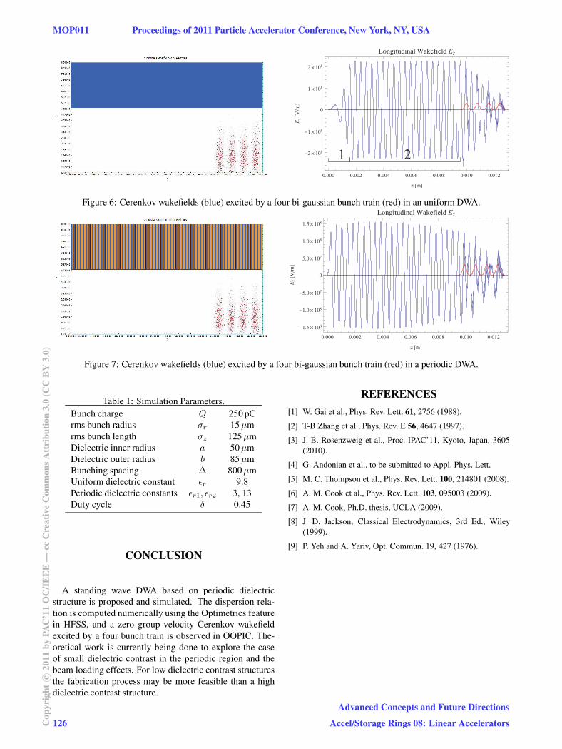
herent Cerenkov wakefields by a bunch train is simulatedfor both uniform and periodic DWA using OOPIC. The twosimulation senarios are both tuned to coherently radiate at750 GHz, and the simulation parameters are summarizedin Table 1. Fig. 6 and 7 shows the Cerenkov wakefieldsexcited by a four bunch driving train in the uniform and pe-riodic DWA respectively. In the case of the uniform DWA,we see a traveling Cerenkov wakefield only occupying re-gion 2, while leaving region 1 vacant. In the case of peri-odic DWA, the entire volume behind the drive train is occu-pied by a standing wakefield oscillating in time with fixednodes and antinodes. While both wakefields are radiatingat the same frequency, we do see noticeable decrease in thefield gradient for the case of periodic DWA (∼150 MeV/mas opposed to ∼220 MeV/m).
Proceedings of 2011 Particle Accelerator Conference, New York, NY, USA MOP011
Advanced Concepts and Future Directions
Accel/Storage Rings 08: Linear Accelerators 125 Cop
yrig
htc ○
2011
byPA
C’1
1O
C/I
EE
E—
ccC
reat
ive
Com
mon
sAtt
ribu
tion
3.0
(CC
BY
3.0)
1 20.000 0.002 0.004 0.006 0.008 0.010 0.012
�2�108
�1�108
0
1�108
2�108
z �m�
E z�V�m�
Longitudinal Wakefield Ez
Figure 6: Cerenkov wakefields (blue) excited by a four bi-gaussian bunch train (red) in an uniform DWA.
0.000 0.002 0.004 0.006 0.008 0.010 0.012
�1.5�108
�1.0�108
�5.0�107
0
5.0�107
1.0�108
1.5�108
z �m�
E z�V�m�
Longitudinal Wakefield Ez
Figure 7: Cerenkov wakefields (blue) excited by a four bi-gaussian bunch train (red) in a periodic DWA.
A standing wave DWA based on periodic dielectricstructure is proposed and simulated. The dispersion rela-tion is computed numerically using the Optimetrics featurein HFSS, and a zero group velocity Cerenkov wakefieldexcited by a four bunch train is observed in OOPIC. The-oretical work is currently being done to explore the caseof small dielectric contrast in the periodic region and thebeam loading effects. For low dielectric contrast structuresthe fabrication process may be more feasible than a highdielectric contrast structure.
REFERENCES
[1] W. Gai et al., Phys. Rev. Lett. 61, 2756 (1988).
[2] T-B Zhang et al., Phys. Rev. E 56, 4647 (1997).
[3] J. B. Rosenzweig et al., Proc. IPAC’11, Kyoto, Japan, 3605(2010).
[4] G. Andonian et al., to be submitted to Appl. Phys. Lett.
[5] M. C. Thompson et al., Phys. Rev. Lett. 100, 214801 (2008).
[6] A. M. Cook et al., Phys. Rev. Lett. 103, 095003 (2009).
[7] A. M. Cook, Ph.D. thesis, UCLA (2009).
[8] J. D. Jackson, Classical Electrodynamics, 3rd Ed., Wiley(1999).
[9] P. Yeh and A. Yariv, Opt. Commun. 19, 427 (1976).
MOP011 Proceedings of 2011 Particle Accelerator Conference, New York, NY, USA