20
Smart IDU Digital Microwave Radio SM Sygnus SHC User’s Manual

Smart IDU Digital Microwave Radio SM Sygnus SHC
User’s Manual

Star Microwave Sygnus Smart IDU
1 CONTENTS
Section Page
1 CONTENTS ..................................................................... 2
2 INTRODUCTION ................................................................. 3
3 INSTALLATION ................................................................. 4
3.1 PACKING LIST ................................................................. 4
4 CONFIGURATION ............................................................... 10
4.1 FUNCTIONAL DESCRIPTION ...................................................... 11
4.2 TRAFFIC PRIORITIZATION ...................................................... 12
4.3 LINK MANAGER MONITORING AND SPECIAL MODES ................................... 13
4.4 SMART IDU WINDOW ............................................................ 14
4.5 TEST MODE ................................................................... 15
4.6 PORTS WINDOW ................................................................ 16
4.7 LOOP MODE ................................................................... 17
5 APPENDIX B: RMA (RETURN MATERIAL AUTHORIZATION) FORM ........................ 18

Star Microwave Sygnus Smart IDU
2 INTRODUCTION
Thank you for purchasing Star Microwave Smart Indoor Unit (S-IDU). Star Microwave S-IDU enables
transmitting TDM (E1/T1) and Ethernet streams over Star Microwave SHC Point-to-Point wireless
backhauls with ultra-low latency, low jitter connectivity, 1+1 backup redundancy and minimal power
consumption.
S-IDU models:
• Ethernet only – Gigabit PoE and 2 Gigabit Ethernet interfaces
• Ethernet + TDM - Gigabit PoE, 2 Gigabit Ethernet interfaces and 1-16 TDM ports
• S-IDU license upgrades:
� 1TDM -> 2TDM -> 4TDM -> 8TDM -> 16TDM.
� 1+1 Hot standby (Ethernet only)
� 1+1 Hot standby (Ethernet + TDM)
Star Microwave PTP and S-IDU Highlights:
• Highest capacity, extremely low latency and interference rejection technologies are optimized for TDM
over IP traffic.
• Efficient protocol ensures high capacity in longest-range links and highest availability.
• Error-free solution via Hitless ACM (Adaptive Coding & Modulation).
• Minimal Jitter via fastest ARQ (Automatic Retransmit reQuest).
• Built in QoS with 8 priority queues.
• 1+1 hot standby with automatic detection of less than 50ms.
• Built in GigE PoE for Star Microwave radios.
• Fully integrated with Star Microwave NMS, SNMP and web-based management.
• Green solution with lowest power consumption in the market.

Star Microwave Sygnus Smart IDU
3 INSTALLATION
3.1 PACKING LIST
When you first open the package, verify that the unit is complete with the following components:
1. Star Microwave S-IDU.
2. Indoor AC-DC power supply.
Figure 2-1: General System View
2.2 Additional part list – required for installation
� Grounding cable.
� Outdoor-to-Indoor shielded CAT5 cable (up to 100 meters).
� Indoor CAT5 cable.
� Indoor TDM cables.
Star Microwave Sygnus Smart IDU
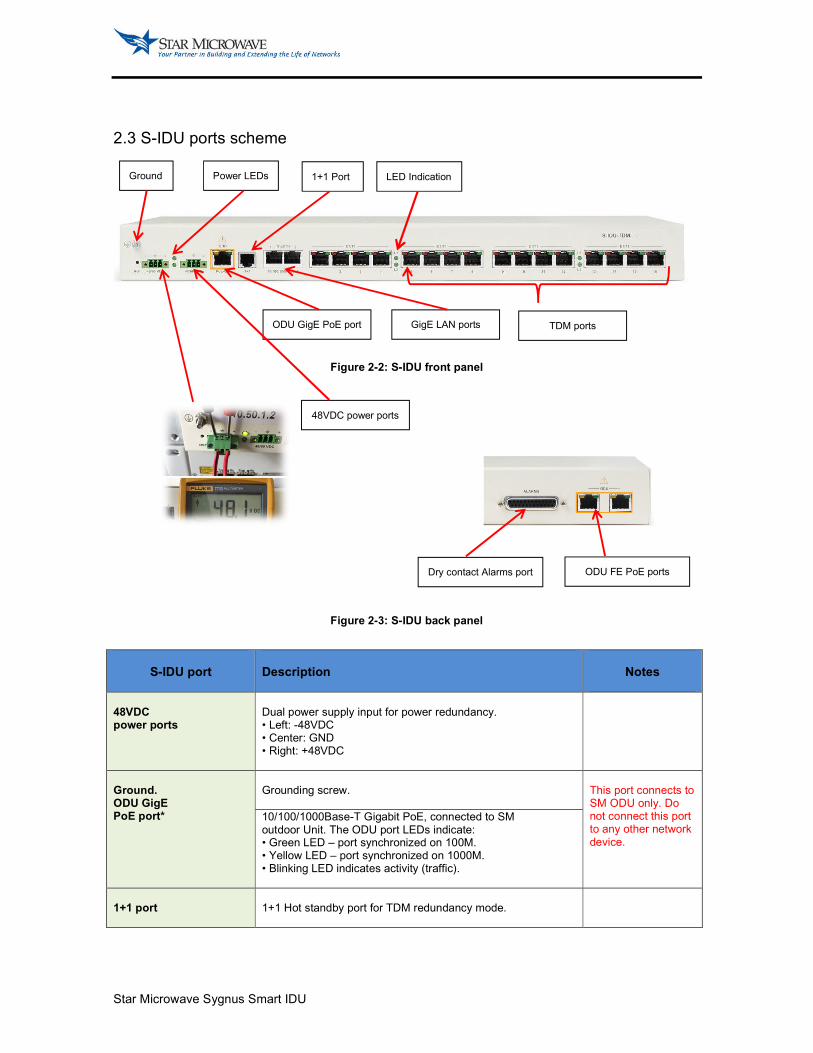
2.3 S-IDU ports scheme
Figure 2-2: S-IDU front panel
Figure 2-3: S-IDU back panel
S-IDU port
Description
Notes
48VDC power ports
Dual power supply input for power redundancy. • Left: -48VDC • Center: GND • Right: +48VDC
Ground. ODU GigE PoE port*
Grounding screw.
This port connects to SM ODU only. Do not connect this port to any other network device.
10/100/1000Base-T Gigabit PoE, connected to SM outdoor Unit. The ODU port LEDs indicate: • Green LED – port synchronized on 100M. • Yellow LED – port synchronized on 1000M. • Blinking LED indicates activity (traffic).
1+1 port
1+1 Hot standby port for TDM redundancy mode.
Ground Power LEDs 1+1 Port LED Indication
48VDC power ports
ODU GigE PoE port GigE LAN ports TDM ports
Dry contact Alarms port ODU FE PoE ports

Star Microwave Sygnus Smart IDU
GigE LAN ports
10/100/1000Base-T Gigabit LAN ports. The port LEDs indicate: • Orange LED (left) – port synchronized on 100M. • Yellow LED (right) – port synchronized on 1000M. • Blinking LED indicates activity (traffic).
TDM ports
E1/T1 ports. The TDM port LEDs indicate: Red LED: • Off – local TDM link is synchronized. • On – local LOS detected. • Blink – External loopback mode enabled. Green LED: • Off – Remote TDM link is synchronized. • On – Remote LOS detected. • Blink – Internal loopback mode enabled.
LOS - Loss of Signal (indicates problem in the connection between the port to the operator TDM device)
LED Indication ODU FE PoE port* [Back panel]
L1: • Off – wireless link offline (MU---SU link is down). • On – wireless link online (MU---SU link is up). • Blink - wireless link online, configuration error. L2: • Off – ODU to S-IDU link is down. • On – ODU to S-IDU link is up. • Blink – S-IDU test mode enabled.
10/100Base-T PoE connected to SM outdoor Unit. The ODU port LEDs indicate activity: • Off – port not connected. • On – port connected no activity (traffic). • Blink - indicates activity (traffic).
This port connects to SM ODU only. Do not connect this port to any other network device.
Dry contact alarms port [Back panel]
4 Outputs + 4 Inputs dry contact alarms.

Star Microwave Sygnus Smart IDU
2.4 Typical installation scheme
S-IDU device is assembled as follows:
1. Plug the outdoor unit (SM) cable to the RJ-45 Jack marked ‘ODU PoE’ using a straight CAT5
Gauge 24-shielded outdoor rated cable (the cable should be UV resistant, flame retardant, UL
listed and contain at least 4 twisted pairs).
Note:
The ‘ODU-PoE’ port is connected to SM radio only. Do not attach standard CAT5 cable from the PC (or other network device) to “ODUPoE” jack. It may damage the PC’s Ethernet interface.
The radio is connected and powered only via the ‘ODU-PoE’ port. Do not connect the radio to any other port.
2. Plug standard CAT5 cable from the PC (or network switch/router) to the RJ-45
Jack marked “GigETH – 10/100/1000 BaseT”.
3. Plug the TDM lines to the RJ-45 jacks marked ‘E1/T1’.
4. Plug the green 48VDC power jack to S-IDU ‘48/60 VDC’ power port.
5. Connect a ground cable between S-IDU and an appropriate grounding point.
6. Plug the AC Input to the power (100-240VAC).
Figure 2-4: Typical installation
SM
Outdoor unit
S-IDU
power
supply
Indoor
CAT5
SM IDU
E1/T1 Cables S-IDU
48 V DC
S-IDU
100 -200 VAC
GROUND
Star Microwave Sygnus Smart IDU
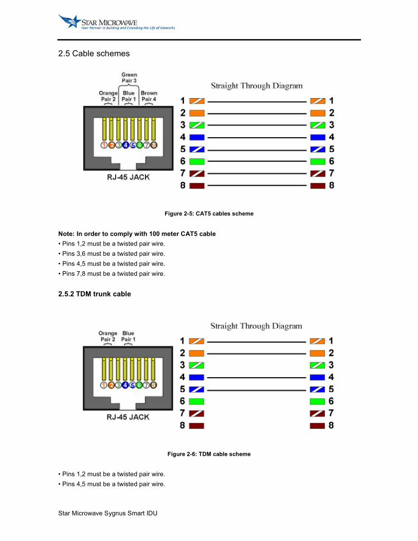
2.5 Cable schemes
Figure 2-5: CAT5 cables scheme
Note: In order to comply with 100 meter CAT5 cable
• Pins 1,2 must be a twisted pair wire.
• Pins 3,6 must be a twisted pair wire.
• Pins 4,5 must be a twisted pair wire.
• Pins 7,8 must be a twisted pair wire.
2.5.2 TDM trunk cable
Figure 2-6: TDM cable scheme
• Pins 1,2 must be a twisted pair wire.
• Pins 4,5 must be a twisted pair wire.

Star Microwave Sygnus Smart IDU
2.6 Grounding
S-IDU unit is connected to Star Microwave outdoor unit, therefore proper grounding is required to protect
against lightning.
It is the operator's responsibility to install and ground S-IDU in accordance with local codes and regulations,
such as ANSI/NFPA No.70-1984
S-IDU earth lug should be connected to the protective earth at all times by a wire with a diameter of 10
AWG or wider.
Units intend to be installed in a Rack should be mounted only in earthed racks and cabinets.
Ground connection should be connected first and disconnected last.
Do not connect telecommunication or any other cables to ungrounded equipment.
Note:
Only experience, trained professionals who are familiar with local building and safety codes and wherever applicable, are licensed by the appropriate regulations should install grounding. Failure to do so may expose the operator to legal and financial liabilities. SM and its resellers or distributors are not liable for injury, damage or violation of regulations associated with the installation of indoor or outdoor units

Star Microwave Sygnus Smart IDU
4 CONFIGURATION
S-IDU parameters are configured via SM radios – the MU and SU.
Figure 3-1: S-IDU WEB configuration
Parameter
Description
Notes
S-IDU mode Jitter Buffer Clock setting Management IP
Select S-IDU TDM interface mode – E1 or T1.
Configure the jitter buffer in msec. Relevant for MU only. Typical configuration = 8msec
Set S-IDU clock configuration: • Loopback-Adaptive (default) • Adaptive-Loopback • Internal-Adaptive • Adaptive-Internal
Relevant for MU only. Default configuration = Loopback-Adaptive
Configure the S-IDU management IP: • In the MU - assign management IP to the S-IDU connected to the MU. • In the SU - assign management IP to the S-IDU connected to the SU.
E1/T1 IP Remote IP
Configure data IP of the TDM payload. • In the MU – configuration must be identical to the ‘Remote IP’ configuration of the SU. • In the SU - configuration must be identical to the ‘Remote IP’ configuration of the MU.
Configure remote data IP of the TDM payload. • In the MU – configuration must be identical to the ‘E1/T1 IP’ configuration of the SU. • In the SU - configuration must be identical to the ‘E1/T1 IP’ configuration of the MU.
S-IDU ports configuration
Port # LOS [port status]
Indicates S-IDU port number.
Display S-IDU port status (for each port): • Black (left) – local TDM link is synchronized. • Red (left) – local LOS detected. • Black (right) – Remote TDM link is synchronized. • Green (right) – Remote LOS detected. • X – port not licensed.
LOS - Loss of Signal (indicates problem in the connection between the port to the operator TDM device)

Star Microwave Sygnus Smart IDU
Enabled Enable/disable S-IDU port.
S-IDU ports status
Max JB Min JB
Maximum Jitter buffer recorded (usec) in the last 2 seconds.
Minimum Jitter buffer recorded (usec) in the last 2 seconds.
Overruns Underruns
Number of port Overruns (must be 0 in normal Operation).
In case value is not 0, try to increase jitter buffer Size.
Number of port Underruns (must be 0 in normal Operation).
In case value is not 0, try to increase jitter buffer Size.
Lost packets TDM over IP lost packets (must be 0 in normal Operation).
In case value is not 0, verify the air link is stable with no PER.
Clear status Clear the counters.
4.1 FUNCTIONAL DESCRIPTION
S-IDU clock settings
TDM traffic is a clocked traffic, where the information (bits) is transmitted at a constant rate. S-IDU converts
the TDM traffic into Ethernet packets and sends it via Star Microwave Point-to-Point link.
The Ethernet traffic is bursty (not constant rate and has variable size), so the main challenge of S-IDU
subsystem is to provide constant rate traffic on both ends, or in other words, producing and transferring the
clock.
There are four clock modes combinations (configured at Star Microwave MU):
S-IDU Clock setting TDM network (User equipment)
MU S-IDU SU S-IDU MU Side SU Side
Loopback Adaptive Internal Adaptive
Adaptive Loopback Adaptive Internal
Internal Adaptive Adaptive Adaptive
Adaptive Internal Adaptive Adaptive
• Loopback-Adaptive - MU S-IDU clock is received via the TDM lines (Loopback) and SU S-IDU recovers it
(Adaptive).
• Adaptive-Loopback - SU S-IDU clock is received via the TDM lines (Loopback) and MU S-IDU recovers it
(Adaptive).
• Internal-Adaptive - The MU S-IDU uses internal clock (Internal) and SU S-IDU recovers it (Adaptive).
• Adaptive-Internal - The SU S-IDU uses internal clock (Internal) and MU S-IDU recovers it (Adaptive).
Star Microwave Sygnus Smart IDU
Page 15 of 24
4.2 TRAFFIC PRIORITIZATION
TDM traffic must be prioritized over Ethernet traffic. For this purpose, SM system includes built in Quality of
Service (QoS) based on 802.1p & 802.1q with 8 priority queues.
Configure SM MU system mode to PTP+TDM to enable Point-to-Point mode optimized for TDM over IP
traffic with built in QoS. This system mode was specifically designed to handle TDM & Ethernet traffic over
the same link, where TDM traffic will be marked with high priority.
The TDM prioritization is done automatically. Star Microwave S-IDU assigns highest priority (7) to the TDM
packets in order to make sure the TDM traffic is prioritized over any other type of traffic.

Star Microwave Sygnus Smart IDU
4.3 LINK MANAGER MONITORING AND SPECIAL MODES
S-IDU parameters and special modes are monitored and configured via the Link
Manager. Connect to S-IDU using the ‘S’ button (start session) in the Link Manager.
Status window
The status window displays basic parameters of S-IDU configuration and GigE ports.
Figure 4-1: Status window
Parameter
Description
Connected Display connection status between S-IDU and SM unit - true/false.
Configured Display configuration status - true/false (indicating whether S-IDU received its Configuration from SM unit).
TDM Test mode Port status
Display TDM status - true/false (indicating S-IDU is ready and air link is up).
Display Test mode configuration – off/master/slave.
Indicates the status of for each GigE port: • Link – port up/down. • Speed – 10/100/1000M • Duplex – Full/half • Flow control – on/off
Star Microwave Sygnus Smart IDU
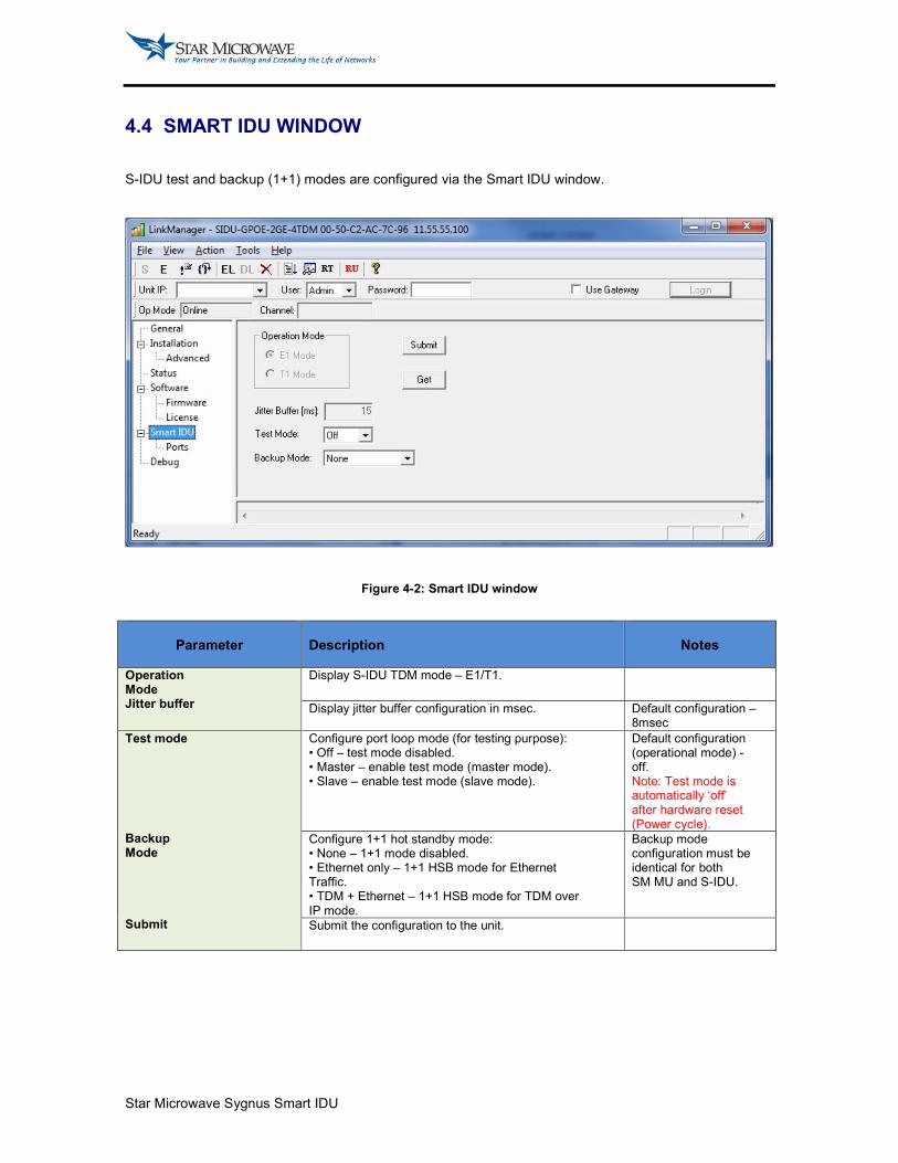
4.4 SMART IDU WINDOW
S-IDU test and backup (1+1) modes are configured via the Smart IDU window.
Figure 4-2: Smart IDU window
Parameter
Description
Notes
Operation Mode Jitter buffer
Display S-IDU TDM mode – E1/T1.
Display jitter buffer configuration in msec. Default configuration – 8msec
Test mode Backup Mode Submit
Configure port loop mode (for testing purpose): • Off – test mode disabled. • Master – enable test mode (master mode). • Slave – enable test mode (slave mode).
Default configuration (operational mode) - off. Note: Test mode is automatically ‘off’ after hardware reset (Power cycle).
Configure 1+1 hot standby mode: • None – 1+1 mode disabled. • Ethernet only – 1+1 HSB mode for Ethernet Traffic. • TDM + Ethernet – 1+1 HSB mode for TDM over IP mode.
Backup mode configuration must be identical for both SM MU and S-IDU.
Submit the configuration to the unit.
Star Microwave Sygnus Smart IDU
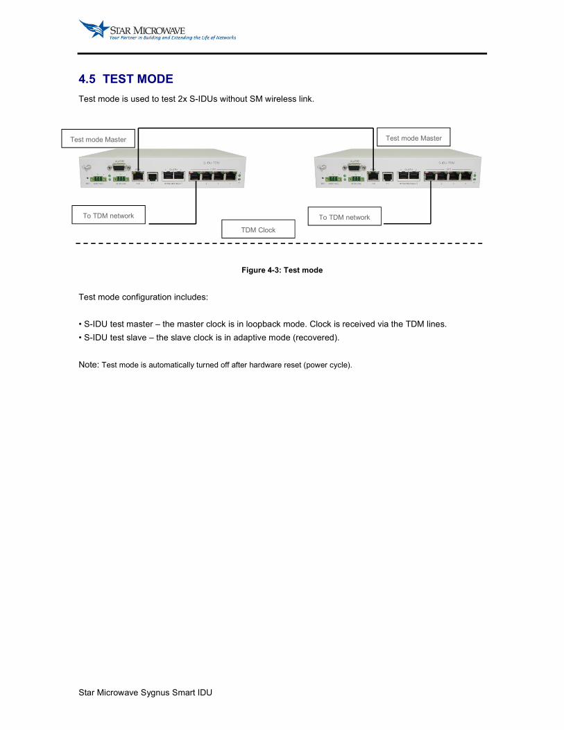
4.5 TEST MODE
Test mode is used to test 2x S-IDUs without SM wireless link.
Figure 4-3: Test mode
Test mode configuration includes:
• S-IDU test master – the master clock is in loopback mode. Clock is received via the TDM lines.
• S-IDU test slave – the slave clock is in adaptive mode (recovered).
Note: Test mode is automatically turned off after hardware reset (power cycle).
Test mode Master Test mode Master
To TDM network To TDM network
TDM Clock

Star Microwave Sygnus Smart IDU
4.6 PORTS WINDOW
The ports window displays S-IDU TDM ports parameters, status and counters.
Figure 4-6: Ports window
Parameter Description
Notes
Ports state Clock mode
Display port configuration – enabled/disabled.
Display clock configuration – loopback/adaptive/internal.
Loop mode Port status
Configure port loop mode (for testing purpose): • Off – loop mode disabled • External – enable external loop. • Internal – enable internal loop. Press ‘submit’ to enable loop mode.
Default configuration (operational mode) - off. Note: loop mode is automatically ‘off’ after unit reset.
Display port counters: • JB max – max Jitter buffer recorded (usec). • JB min – min Jitter buffer recorded (usec). • Underruns – number of port Underruns (must be 0 in normal operation). • Packets Tx – transmitted TDM over IP packets. • Packets Rx – received TDM over IP packets. • Lost packets – TDM over IP lost packets (must be 0 in normal operation).
Underruns – in case value is not 0, try to increase jitter buffer size. Lost packets - in case value is not 0, verify the air link is stable with no PER.
Clear status Clear all status Port tab
Clear the port’s counters.
Clear the counters of all ports.
Display S-IDU port status (for each port): • Black (left) – local TDM link is synchronized. • Red (left) – local LOS (Loss of Signal) detected. • Black (right) – Remote TDM link is synchronized. • Green (right) – Remote LOS (Loss of Signal) detected.
Star Microwave Sygnus Smart IDU
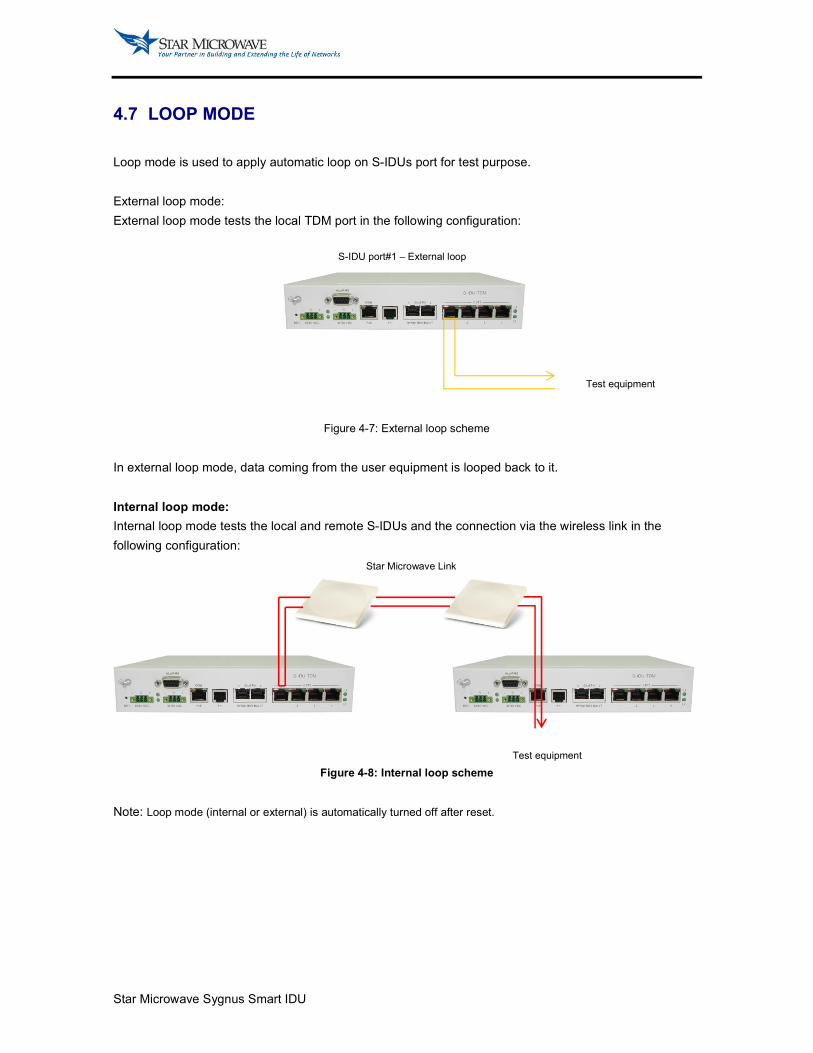
4.7 LOOP MODE
Loop mode is used to apply automatic loop on S-IDUs port for test purpose.
External loop mode:
External loop mode tests the local TDM port in the following configuration:
Figure 4-7: External loop scheme
In external loop mode, data coming from the user equipment is looped back to it.
Internal loop mode:
Internal loop mode tests the local and remote S-IDUs and the connection via the wireless link in the
following configuration:
Figure 4-8: Internal loop scheme
Note: Loop mode (internal or external) is automatically turned off after reset.
S-IDU port#1 – External loop
Test equipment
Star Microwave Link
Test equipment

Star Microwave Sygnus Smart IDU
5 APPENDIX B: RMA (RETURN MATERIAL AUTHORIZATION) FORM
Star Microwave Service Corporation
41458 Christy Street Fremont, CA 94538-6547 Telephone: +1 510.498.7900 Fax +1 510.498.7901
RMA Request Form
Date:
From :
Address :
Tel :
Fax :
E-mail:
ATTN:
Product Information :
Item Model Serial Number Return Category Qty Problem Description
1
2
3
4
5
6
7
8
9
10
Notes:
1. For 'Return Category' column, please select from A: Return of Defective Product, B: Return of Trial Sample, or C: Return
of New and Unused Product.
2. If A or C category of return product is chosen, please give short description of the problem or reason for returning.
Transportation Information:
Location of Product:
Transportation Method:
Shipping Forwarder
Note: Location of Product' must be stated, while 'Transportation Method' or 'Shipping Forwarder' can be left blank if
not determined.
Signature:
Star Microwave Sygnus Smart IDU
--End of Document

Star Microwave Sygnus Smart IDU
Star Microwave Service Corporation
41458 Christy Street
Fremont, CA. 94538
Tel: +1 510.498.7900
Fax: +1 510.498.7901


