32
USER MANUAL STARK400 MOVING HEAD EN

USER MANUAL
STARK400MOVING HEAD
EN

All rights reserved by PROLIGHTS No part of this instruction manual may be reproduced in any form or by any means for any commercial use.
In order to improve the quality of products, PROLIGHTS reserves the right to modify the characteristics stated in this instruction manual at any time and without prior notice.
All revisions and updates are available in the ‘manuals’ section on site www.prolightsamerica.com
REV.002-02/18 - FW 2.0.01
1STARK400
Packing content • STARK400• Mount bracket• User manual
TABLE OF CONTENTS SafetyGeneral instructionsWarnings and installation precautions
1 Introduction1. 1 Description 1. 2 Technical specifications1. 3 Operating elements and connections
2 Installation2. 1 Mounting
3 Functions and settings3. 1 Operation3. 2 Basic3. 3 Menu structure3. 4 Slave Receive mode3. 5 Operation in automatic mode3. 6 Scenes Record mode3. 7 Music mode 3. 8 Sensitivity microphone3. 9 Linking 3. 10 DMX mode3. 11 DMX configuration 3. 12 DMX addressing 3. 13 Connection of the DMX line 3. 14 Construction of the DMX termination 3. 15 DMX control3. 16 Channel Function3. 17 Wireless control settings 3. 18 Fixture settings 3. 19 Lamp settings 3. 20 Display settings 3. 21 Special functions3. 22 Fixture information
4 Maintenance4. 1 Maintenance and cleaning the unit4. 2 Fuse replacement4. 3 Trouble shooting
22
336
7
88911111313131414141416161722232324242525
272728

STARK4002
WARNING! Before carrying out any operations with the unit, carefully read this instruction manual and keep it with cure for future reference. It contains important information about the installation, usage and maintenance of the unit.
SAFETY
General instruction• The products referred to in this manual conform to the European Community Directives and are there-
fore marked with and approved for the North American Market. • The unit is supplied with hazardous network voltage (120V~). Leave servicing to skilled personnel only.
Never make any modifications on the unit not described in this instruction manual, otherwise you will risk an electric shock.
• Connection must be made to a power supply system fitted with efficient earthing (Class I appliance ac-cording to standard EN 60598-1). It is, moreover, recommended to protect the supply lines of the units from indirect contact and/or shorting to earth by using appropriately sized residual current devices.
• The connection to the main network of electric distribution must be carried out by a qualified electrical installer. Check that the main frequency and voltage correspond to those for which the unit is designed as given on the electrical data label.
• This unit is not for home use, only professional applications.• Never use the fixture under the following conditions:
- in places wet;- in places subject to vibrations or bumps;- in places with an ambient temperature of over 45°C.
• Make certain that no inflammable liquids, water or metal objects enter the fixture.• Do not dismantle or modify the fixture.• All work must always be carried out by qualified technical personnel. Contact the nearest sales point for
an inspection or contact the manufacturer directly.• If the unit is to be put out of operation definitively, take it to a local recycling
plant for a disposal which is not harmful to the environment.Warnings and installation precautions• If this device will be operated in any way different to the one described in this manual, it may suffer
damage and the guarantee becomes void. Furthermore, any other operation may lead to dangers like short circuit, burns, electric shock, etc.
• Before starting any maintenance work or cleaning the projector, cut off power from the main supply.• Always additionally secure the projector with the safety rope. When carrying out any work, always com-
ply scrupulously with all the regulations (particularly regarding safety) currently in force in the country in which the fixture’s being used.
• For inside use only. Not designed for outside use.• The minimum distance between the fixture and surrounding walls must be more than 50 cm and the
air vents at the housing must not be covered in any case.• Install the fixture in a well ventilated place.• Keep any inflammable material at a safe distance from the fixture.• The maximum temperature that can be reached on the external surface of the fitting, in a thermally
steady state, is high. After power off, please cool down over 15 minutes.• Shields, lenses or ultraviolet screens shall be changed if they have become damaged to such an extent
that their effectiveness is impaired.• The lamp (LED) shall be changed if it has become damaged or thermally deformed.• Never look directly at the light beam. Please note that fast changes in lighting, e. g. flashing light, may
trigger epileptic seizures in photosensitive persons or persons with epilepsy.
3STARK400
- 1 - INTRODUCTION
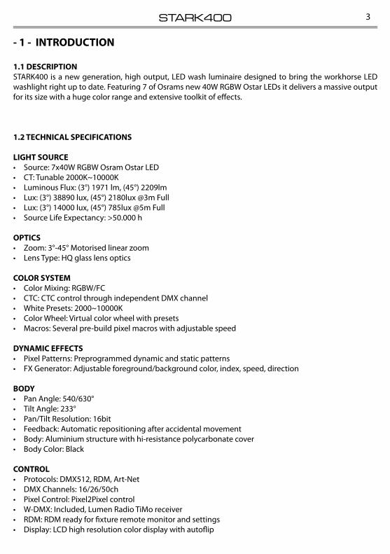
1.1 DESCRIPTIONSTARK400 is a new generation, high output, LED wash luminaire designed to bring the workhorse LED washlight right up to date. Featuring 7 of Osrams new 40W RGBW Ostar LEDs it delivers a massive output for its size with a huge color range and extensive toolkit of effects.
1.2 TECHNICAL SPECIFICATIONS
LIGHT SOURCE• Source: 7x40W RGBW Osram Ostar LED• CT: Tunable 2000K~10000K• Luminous Flux: (3°) 1971 lm, (45°) 2209lm• Lux: (3°) 38890 lux, (45°) 2180lux @3m Full• Lux: (3°) 14000 lux, (45°) 785lux @5m Full• Source Life Expectancy: >50.000 h
OPTICS• Zoom: 3°-45° Motorised linear zoom• Lens Type: HQ glass lens optics
COLOR SYSTEM• Color Mixing: RGBW/FC• CTC: CTC control through independent DMX channel• White Presets: 2000~10000K• Color Wheel: Virtual color wheel with presets• Macros: Several pre-build pixel macros with adjustable speed
DYNAMIC EFFECTS• Pixel Patterns: Preprogrammed dynamic and static patterns• FX Generator: Adjustable foreground/background color, index, speed, direction
BODY• Pan Angle: 540/630°• Tilt Angle: 233°• Pan/Tilt Resolution: 16bit• Feedback: Automatic repositioning after accidental movement• Body: Aluminium structure with hi-resistance polycarbonate cover• Body Color: Black
CONTROL• Protocols: DMX512, RDM, Art-Net• DMX Channels: 16/26/50ch• Pixel Control: Pixel2Pixel control• W-DMX: Included, Lumen Radio TiMo receiver• RDM: RDM ready for fixture remote monitor and settings• Display: LCD high resolution color display with autoflip
STARK4004
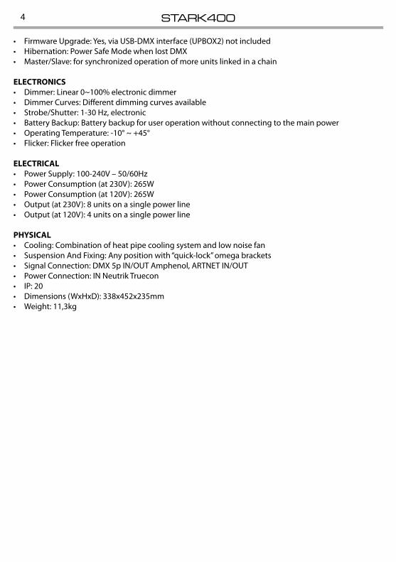
• Firmware Upgrade: Yes, via USB-DMX interface (UPBOX2) not included• Hibernation: Power Safe Mode when lost DMX• Master/Slave: for synchronized operation of more units linked in a chain
ELECTRONICS• Dimmer: Linear 0~100% electronic dimmer• Dimmer Curves: Different dimming curves available• Strobe/Shutter: 1-30 Hz, electronic• Battery Backup: Battery backup for user operation without connecting to the main power• Operating Temperature: -10° ~ +45°• Flicker: Flicker free operation
ELECTRICAL• Power Supply: 100-240V – 50/60Hz• Power Consumption (at 230V): 265W• Power Consumption (at 120V): 265W• Output (at 230V): 8 units on a single power line• Output (at 120V): 4 units on a single power line
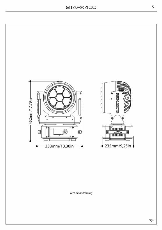
PHYSICAL• Cooling: Combination of heat pipe cooling system and low noise fan• Suspension And Fixing: Any position with “quick-lock” omega brackets• Signal Connection: DMX 5p IN/OUT Amphenol, ARTNET IN/OUT• Power Connection: IN Neutrik Truecon• IP: 20• Dimensions (WxHxD): 338x452x235mm• Weight: 11,3kg
5STARK400
Technical drawing
Fig.1
452m
m/1
7,79
in
338mm/13,30in 235mm/9,25in
ENTER
STARK4006
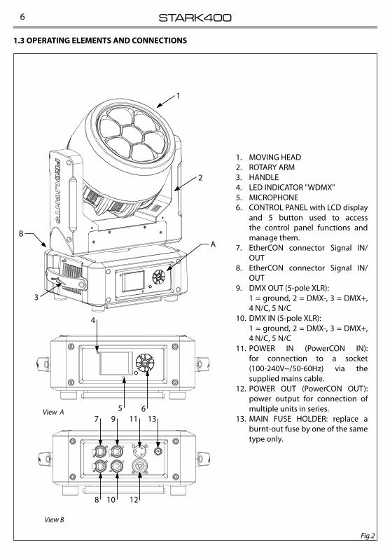
1. MOVING HEAD2. ROTARY ARM3. HANDLE4. LED INDICATOR "WDMX"5. MICROPHONE6. CONTROL PANEL with LCD display
and 5 button used to access the control panel functions and manage them.
7. EtherCON connector Signal IN/OUT
8. EtherCON connector Signal IN/OUT
9. DMX OUT (5-pole XLR):1 = ground, 2 = DMX-, 3 = DMX+, 4 N/C, 5 N/C
10. DMX IN (5-pole XLR):1 = ground, 2 = DMX-, 3 = DMX+, 4 N/C, 5 N/C
11. POWER IN (PowerCON IN): for connection to a socket (100-240V~/50-60Hz) via the supplied mains cable.
12. POWER OUT (PowerCON OUT): power output for connection of multiple units in series.
13. MAIN FUSE HOLDER: replace a burnt-out fuse by one of the same type only.
1.3 OPERATING ELEMENTS AND CONNECTIONS
Fig.2
View A
View B
4
AB
1
2
3
5 67 9 11 13
8 10 12
7STARK400
- 2 - INSTALLATION
Fig.3
Fig.4
ALISCAFFCLAMP
SAFETYCABLE
OMEGABRACKETS
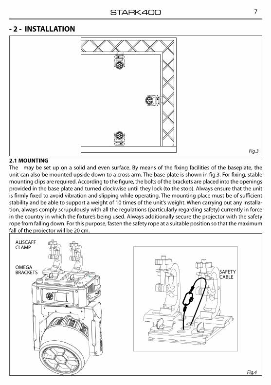
2.1 MOUNTINGThe may be set up on a solid and even surface. By means of the fixing facilities of the baseplate, the unit can also be mounted upside down to a cross arm. The base plate is shown in fig.3. For fixing, stable mounting clips are required. According to the figure, the bolts of the brackets are placed into the openings provided in the base plate and turned clockwise until they lock (to the stop). Always ensure that the unit is firmly fixed to avoid vibration and slipping while operating. The mounting place must be of sufficient stability and be able to support a weight of 10 times of the unit’s weight. When carrying out any installa-tion, always comply scrupulously with all the regulations (particularly regarding safety) currently in force in the country in which the fixture’s being used. Always additionally secure the projector with the safety rope from falling down. For this purpose, fasten the safety rope at a suitable position so that the maximum fall of the projector will be 20 cm.
STARK4008
- 3 - FUNCTIONS AND SETTINGS
3.1 OPERATIONConnect the supplied main cable to a socket (120V~60Hz). The unit will run built-in program to reset all motors to their home position. Shortly after that the STARK400 is ready for operation. To switch off, discon-nect the mains plug from the socket. For a more convenient operation it is recommended to connect the unit to a socket which can be switched on and off via light switch.
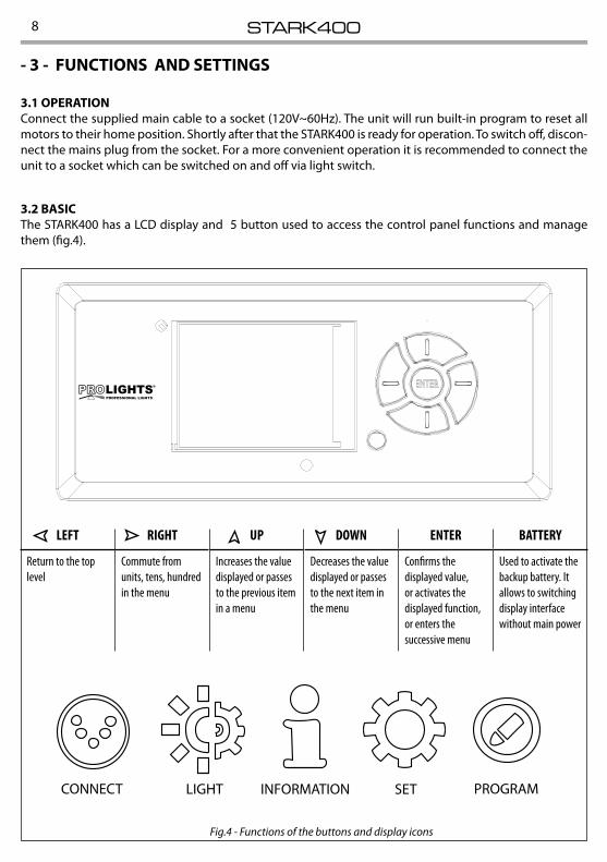
3.2 BASICThe STARK400 has a LCD display and 5 button used to access the control panel functions and manage them (fig.4).
Fig.4 - Functions of the buttons and display icons
CONNECT LIGHT INFORMATION SET PROGRAM
LEFT RIGHT UP DOWN ENTER BATTERY
Return to the top level
Commute from units, tens, hundred in the menu
Increases the value displayed or passes to the previous item in a menu
Decreases the value displayed or passes to the next item in the menu
Confirms the displayed value, or activates the displayed function, or enters the successive menu
Used to activate the backup battery. It allows to switching display interface without main power

9STARK400
3.3 MENU STRUCTURE
MENU
1 CONNECT ð Address ð DMX ð Value (1-512)
W-DMX ð Value (1-512)
Artnet ð Value (1-512)
DMX Mode ð Mode ð WASH / FX / PIXFX
Edit User ð Max Channel/Control/Pan/Pan Fine/Tilt/...
Wireless ð DMX Out ð ON/OFF
Reset Connect ð YES/NO
Ethernet ð DMX Out ð ON/OFF
IP Address ð 2.XX.XX.01
IP Mask ð 255.0.0.0
Universe ð 00000
RDM ID ð Name ð Fixture ID Name
Password ð 050 (unlocks the following settings)
PID Code ð 00001
2 SET UP ð Temperature ð Temperature C/F ð Celsius/Fahrenheit
Max Temperature ð Value (60°-139° C)
Movement ð Pan Reverse ð YES/NO
Tilt Reverse ð YES/NO
Pan Degree ð 540/630
Pan/Tilt Feedbacks ð YES/NO
Pan/Tilt Mode ð Standard/Smooth
Screen ð Backlight ð Always On/Min (01-99)
Flip Display ð YES/NO/AUTO
Display Bright ð Value (00-31)
Key Lock ð ON/OFF
Language ð EN/FR/SP...
Fixture ð Fans Mode ð Auto Speed/High Speed
No Signal ð Close/Hold/Auto/Music
Hibernation ð Disable/Min (01-99)
Theater Mode ð YES/NO
Adjust ð Control, Pan, Pan Fine, Tilt, Tilt Fine, Pan&Tilt Speed, Shutter, Dimmer, Dimmer Fade, [...]
ð Value (000-255) for each function
STARK40010
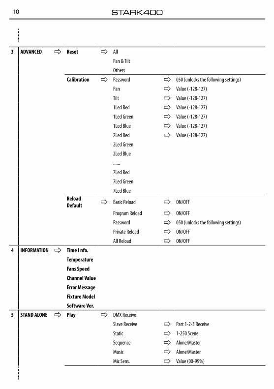
3 ADVANCED ð Reset ð All
Pan & Tilt
Others
Calibration ð Password ð 050 (unlocks the following settings)
Pan ð Value (-128-127)
Tilt ð Value (-128-127)
1Led Red ð Value (-128-127)
1Led Green ð Value (-128-127)
1Led Blue ð Value (-128-127)
2Led Red ð Value (-128-127)
2Led Green
2Led Blue
......
7Led Red
7Led Green
7Led BlueReload Default ð Basic Reload ð ON/OFF
Program Reload ð ON/OFF
Password ð 050 (unlocks the following settings)
Private Reload ð ON/OFF
All Reload ð ON/OFF
4 INFORMATION ð Time I nfo.
Temperature
Fans Speed
Channel Value
Error Message
Fixture Model
Software Ver.
5 STAND ALONE ð Play ð DMX Receive
Slave Receive ð Part 1-2-3 Receive
Static ð 1-250 Scene
Sequence ð Alone/Master
Music ð Alone/Master
Mic Sens. ð Value (00-99%)
11STARK400
3.4 SLAVE RECEIVE MODEThis mode will allow you to link up the units together without a controller. Choose a unit to function as the Master. The unit must be the first unit in line; other units will work as slave with the same effect.A Master unit can send up to 3 different data groups to the Slave units, i.e. a Master unit can start 3 differ-ent Slave units, which run 3 different programs. The Master unit sends the 3 program parts in a continuous loop.The Slave unit receives data from the Master unit according to the group which the Slave unit was as-signed to.For example, if a slave device is set to Receive Part 1, the Master unit Slave unit will send the automated Chase Part 1; if set to Receive Part 2, the Chase Part 2 Slave units will receive from the Master.To set the drive as a slave, proceed as follows:• Press the ENTER button to access the main menu.• Press the UP/DOWN button to scroll the menu, select the Program icon, then press the ENTER button to
enter the next menu.• Press the UP/DOWN button to scroll through the menu, and then select Play and press the ENTER
button to enter the next menu.• Press the UP/DOWN button to scroll through the menu, and select Slave Receive and press ENTER to
confirm.• Press the UP/DOWN button to select the different modes of operation Part 1 Receive/Receive Part 2/Part 3
Receive, and then press the ENTER button to confirm your choice.• Press the LEFT button repeatedly to exit the menu and save changes.Select the desired program on the master unit (described in section 3.5).Use the DMX connectors of the STARK400 and an XLR cable to form a chain of units. Under certain conditions and lengths you want to make a termination as shown on page 17.
3.5 OPERATIONS IN AUTOMATIC MODEThe unit independently runs through its show. Before you send an automatic program you need to set the drive as Master/Alone:• Press the ENTER button to access the main menu.• Press the UP/DOWN button to scroll the menu, select the Program icon, then press the ENTER button to
enter the next menu.• Press the UP/DOWN button to scroll through the menu, select Play and press the ENTER button to enter
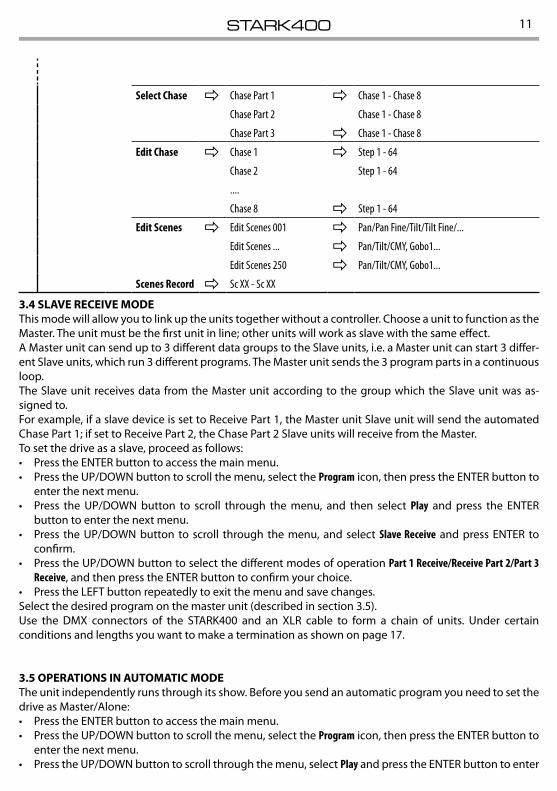
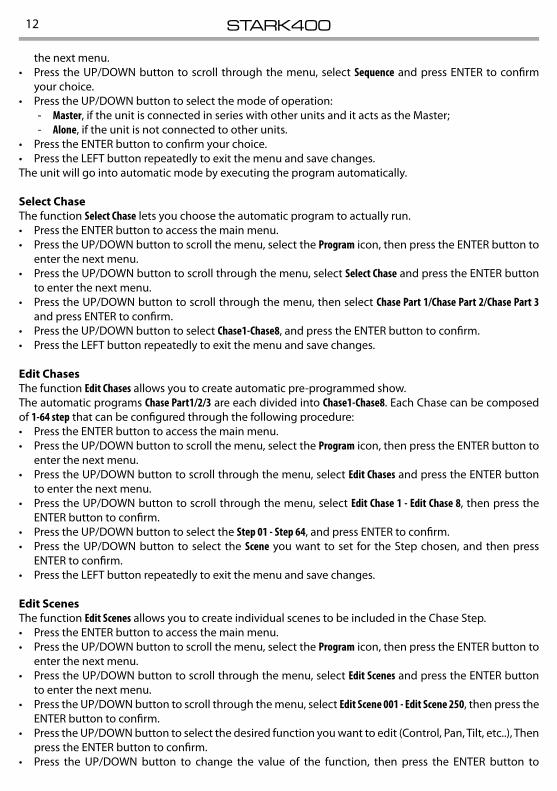
Select Chase ð Chase Part 1 ð Chase 1 - Chase 8
Chase Part 2 Chase 1 - Chase 8
Chase Part 3 ð Chase 1 - Chase 8
Edit Chase ð Chase 1 ð Step 1 - 64
Chase 2 Step 1 - 64
....
Chase 8 ð Step 1 - 64
Edit Scenes ð Edit Scenes 001 ð Pan/Pan Fine/Tilt/Tilt Fine/...
Edit Scenes ... ð Pan/Tilt/CMY, Gobo1...
Edit Scenes 250 ð Pan/Tilt/CMY, Gobo1...
Scenes Record ð Sc XX - Sc XX
STARK40012
the next menu.• Press the UP/DOWN button to scroll through the menu, select Sequence and press ENTER to confirm
your choice.• Press the UP/DOWN button to select the mode of operation:
- Master, if the unit is connected in series with other units and it acts as the Master; - Alone, if the unit is not connected to other units.
• Press the ENTER button to confirm your choice.• Press the LEFT button repeatedly to exit the menu and save changes.The unit will go into automatic mode by executing the program automatically.
Select ChaseThe function Select Chase lets you choose the automatic program to actually run.• Press the ENTER button to access the main menu.• Press the UP/DOWN button to scroll the menu, select the Program icon, then press the ENTER button to
enter the next menu.• Press the UP/DOWN button to scroll through the menu, select Select Chase and press the ENTER button
to enter the next menu.• Press the UP/DOWN button to scroll through the menu, then select Chase Part 1/Chase Part 2/Chase Part 3
and press ENTER to confirm.• Press the UP/DOWN button to select Chase1-Chase8, and press the ENTER button to confirm.• Press the LEFT button repeatedly to exit the menu and save changes.
Edit ChasesThe function Edit Chases allows you to create automatic pre-programmed show.The automatic programs Chase Part1/2/3 are each divided into Chase1-Chase8. Each Chase can be composed of 1-64 step that can be configured through the following procedure:• Press the ENTER button to access the main menu.• Press the UP/DOWN button to scroll the menu, select the Program icon, then press the ENTER button to
enter the next menu.• Press the UP/DOWN button to scroll through the menu, select Edit Chases and press the ENTER button
to enter the next menu.• Press the UP/DOWN button to scroll through the menu, select Edit Chase 1 - Edit Chase 8, then press the
ENTER button to confirm.• Press the UP/DOWN button to select the Step 01 - Step 64, and press ENTER to confirm.• Press the UP/DOWN button to select the Scene you want to set for the Step chosen, and then press
ENTER to confirm.• Press the LEFT button repeatedly to exit the menu and save changes.
Edit ScenesThe function Edit Scenes allows you to create individual scenes to be included in the Chase Step.• Press the ENTER button to access the main menu.• Press the UP/DOWN button to scroll the menu, select the Program icon, then press the ENTER button to
enter the next menu.• Press the UP/DOWN button to scroll through the menu, select Edit Scenes and press the ENTER button
to enter the next menu.• Press the UP/DOWN button to scroll through the menu, select Edit Scene 001 - Edit Scene 250, then press the
ENTER button to confirm.• Press the UP/DOWN button to select the desired function you want to edit (Control, Pan, Tilt, etc..), Then
press the ENTER button to confirm.• Press the UP/DOWN button to change the value of the function, then press the ENTER button to
13STARK400
confirm.• Press the LEFT button repeatedly to exit the menu and save changes.
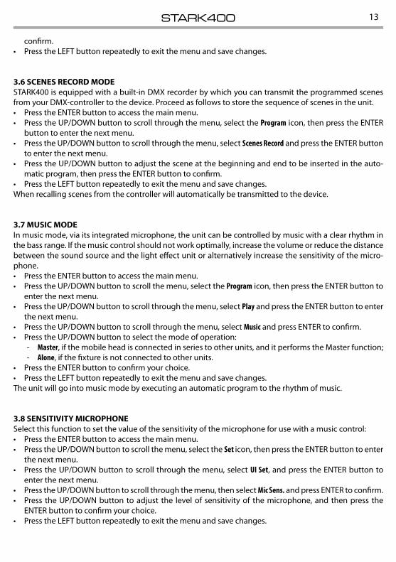
3.6 SCENES RECORD MODESTARK400 is equipped with a built-in DMX recorder by which you can transmit the programmed scenes from your DMX-controller to the device. Proceed as follows to store the sequence of scenes in the unit.• Press the ENTER button to access the main menu.• Press the UP/DOWN button to scroll through the menu, select the Program icon, then press the ENTER
button to enter the next menu.• Press the UP/DOWN button to scroll through the menu, select Scenes Record and press the ENTER button
to enter the next menu.• Press the UP/DOWN button to adjust the scene at the beginning and end to be inserted in the auto-
matic program, then press the ENTER button to confirm.• Press the LEFT button repeatedly to exit the menu and save changes.When recalling scenes from the controller will automatically be transmitted to the device.
3.7 MUSIC MODEIn music mode, via its integrated microphone, the unit can be controlled by music with a clear rhythm in the bass range. If the music control should not work optimally, increase the volume or reduce the distance between the sound source and the light effect unit or alternatively increase the sensitivity of the micro-phone.• Press the ENTER button to access the main menu.• Press the UP/DOWN button to scroll the menu, select the Program icon, then press the ENTER button to
enter the next menu.• Press the UP/DOWN button to scroll through the menu, select Play and press the ENTER button to enter
the next menu.• Press the UP/DOWN button to scroll through the menu, select Music and press ENTER to confirm.• Press the UP/DOWN button to select the mode of operation:
- Master, if the mobile head is connected in series to other units, and it performs the Master function; - Alone, if the fixture is not connected to other units.
• Press the ENTER button to confirm your choice.• Press the LEFT button repeatedly to exit the menu and save changes.The unit will go into music mode by executing an automatic program to the rhythm of music.
3.8 SENSITIVITY MICROPHONESelect this function to set the value of the sensitivity of the microphone for use with a music control:• Press the ENTER button to access the main menu.• Press the UP/DOWN button to scroll the menu, select the Set icon, then press the ENTER button to enter
the next menu.• Press the UP/DOWN button to scroll through the menu, select UI Set, and press the ENTER button to
enter the next menu.• Press the UP/DOWN button to scroll through the menu, then select Mic Sens. and press ENTER to confirm.• Press the UP/DOWN button to adjust the level of sensitivity of the microphone, and then press the
ENTER button to confirm your choice.• Press the LEFT button repeatedly to exit the menu and save changes.
STARK40014
3.9 LINKINGSeveral units may be interconnected in order to control all further slave units to the same effect of the master unit.1. Connect the DMX OUT of the master unit via 5-pole XLR cable to the DMX IN of the first slave unit.2. Connect the DMX OUT of the first slave unit to the DMX IN of the second slave unit, etc. until all units
are connected in a chain.
3.10 DMX MODETo enter the DMX mode, follow these steps:• Press the ENTER button to access the main menu.• Press the UP/DOWN button to scroll the menu, select the Connect icon, then press the ENTER button to
enter the next menu.• Press the UP/DOWN button to scroll through the menu, select the DMX Address and press the ENTER key.• Press the arrow keys to select the desired value (001-512).• Press the ENTER key to confirm the setting.• Press the LEFT button repeatedly to exit the menu and save changes.
3.11 DMX CONFIGURATIONThe STARK400 has 3 DMX channel configurations which can be accessed from the control panel.• Press the ENTER button to access the main menu.• Press the UP/DOWN button to scroll the menu, select the Set icon, then press the ENTER button to enter
the next menu.• Press the UP/DOWN button to scroll through the menu, select Users and press the ENTER button to
enter the next menu.• Press the UP/DOWN button to scroll through the menu, select User Mode and press ENTER to confirm
your choice.• Use the UP/DOWN button to select the desired DMX channel configuration (Wash, FX, PIX-FX, User), then
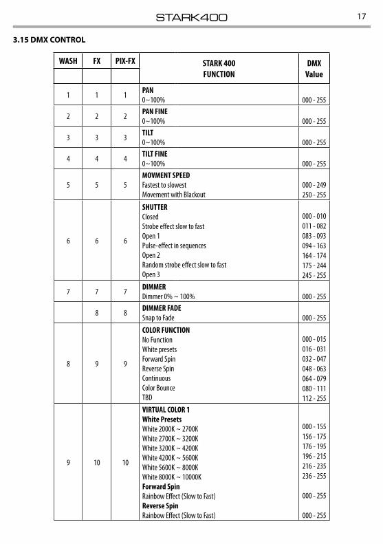
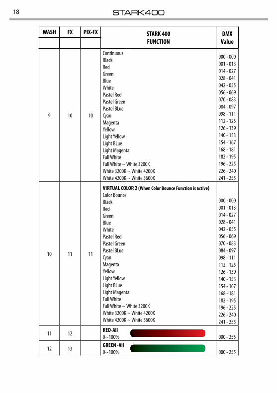
press the ENTER button to confirm your choice.• Press the LEFT button repeatedly to exit the menu and save changes.The tables on page 17 show the mode of operation and their values DMX.The unit is equipped with 5-pole XLR connections.
Edit UserThe Edit User, in the same menu, allows you to create a profile of personalized functions. You can change the parameters of the various functions (Control, Pan, Tilt, etc.). Once you’ve created your custom profile, you can use it by selecting the USER mode as described above.
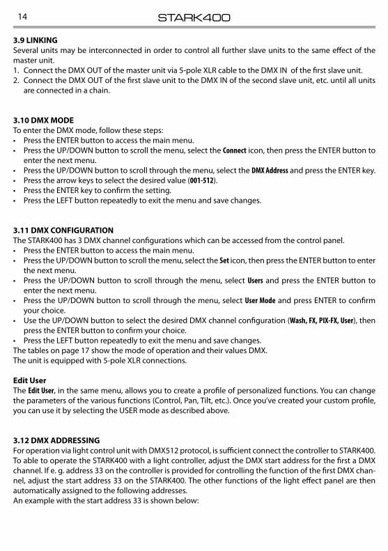
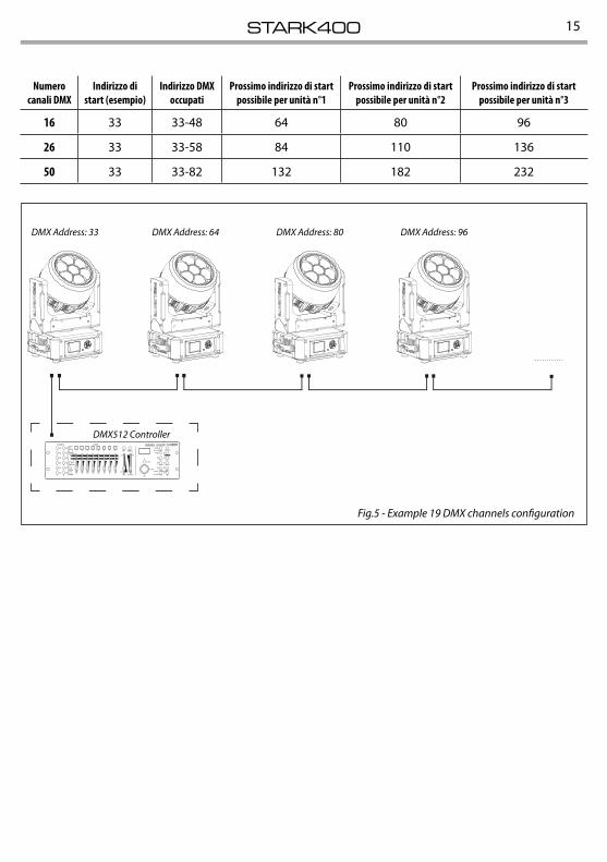
3.12 DMX ADDRESSINGFor operation via light control unit with DMX512 protocol, is sufficient connect the controller to STARK400. To able to operate the STARK400 with a light controller, adjust the DMX start address for the first a DMX channel. If e. g. address 33 on the controller is provided for controlling the function of the first DMX chan-nel, adjust the start address 33 on the STARK400. The other functions of the light effect panel are then automatically assigned to the following addresses.An example with the start address 33 is shown below:
15STARK400
Fig.5 - Example 19 DMX channels configuration
DMX Address: 96DMX Address: 64DMX Address: 33 DMX Address: 80
. . . . . . . . . . . .
DMX512 Controller
Numerocanali DMX
Indirizzo di start (esempio)
Indirizzo DMX occupati
Prossimo indirizzo di start possibile per unità n°1
Prossimo indirizzo di start possibile per unità n°2
Prossimo indirizzo di start possibile per unità n°3
16 33 33-48 64 80 96
26 33 33-58 84 110 136
50 33 33-82 132 182 232
STARK40016
Fig.6
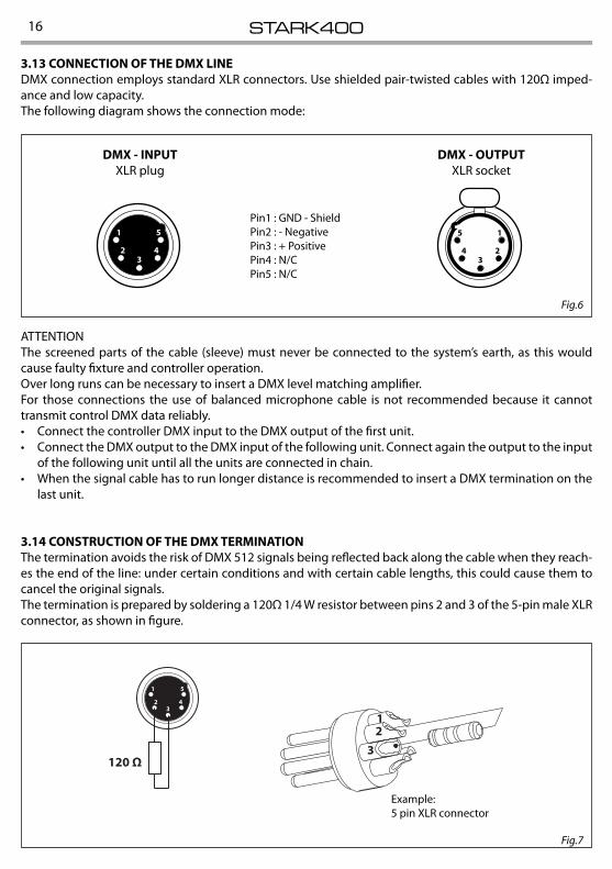
3.13 CONNECTION OF THE DMX LINEDMX connection employs standard XLR connectors. Use shielded pair-twisted cables with 120Ω imped-ance and low capacity.The following diagram shows the connection mode:
ATTENTIONThe screened parts of the cable (sleeve) must never be connected to the system’s earth, as this would cause faulty fixture and controller operation.Over long runs can be necessary to insert a DMX level matching amplifier. For those connections the use of balanced microphone cable is not recommended because it cannot transmit control DMX data reliably. • Connect the controller DMX input to the DMX output of the first unit.• Connect the DMX output to the DMX input of the following unit. Connect again the output to the input
of the following unit until all the units are connected in chain.• When the signal cable has to run longer distance is recommended to insert a DMX termination on the
last unit.
3.14 CONSTRUCTION OF THE DMX TERMINATIONThe termination avoids the risk of DMX 512 signals being reflected back along the cable when they reach-es the end of the line: under certain conditions and with certain cable lengths, this could cause them to cancel the original signals.The termination is prepared by soldering a 120Ω 1/4 W resistor between pins 2 and 3 of the 5-pin male XLR connector, as shown in figure.
DMX - OUTPUTXLR socket
DMX - INPUTXLR plug
Pin1 : GND - ShieldPin2 : - NegativePin3 : + PositivePin4 : N/CPin5 : N/C
Fig.7
Example:5 pin XLR connector
17STARK400
3.15 DMX CONTROL
WASH FX PIX-FX STARK 400FUNCTION
DMXValue
1 1 1 PAN 0~100% 000 - 255
2 2 2 PAN FINE0~100% 000 - 255
3 3 3 TILT0~100% 000 - 255
4 4 4 TILT FINE0~100% 000 - 255
5 5 5MOVMENT SPEEDFastest to slowestMovement with Blackout
000 - 249250 - 255
6 6 6
SHUTTERClosedStrobe effect slow to fastOpen 1Pulse-effect in sequencesOpen 2Random strobe effect slow to fastOpen 3
000 - 010011 - 082083 - 093094 - 163164 - 174175 - 244245 - 255
7 7 7 DIMMERDimmer 0% ~ 100% 000 - 255
8 8 DIMMER FADESnap to Fade 000 - 255
8 9 9
COLOR FUNCTIONNo FunctionWhite presetsForward SpinReverse SpinContinuousColor BounceTBD
000 - 015016 - 031032 - 047048 - 063064 - 079080 - 111112 - 255
9 10 10
VIRTUAL COLOR 1White PresetsWhite 2000K ~ 2700KWhite 2700K ~ 3200KWhite 3200K ~ 4200KWhite 4200K ~ 5600KWhite 5600K ~ 8000KWhite 8000K ~ 10000KForward SpinRainbow Effect (Slow to Fast)Reverse SpinRainbow Effect (Slow to Fast)
000 - 155156 - 175176 - 195196 - 215216 - 235236 - 255
000 - 255
000 - 255
STARK40018
WASH FX PIX-FX STARK 400FUNCTION
DMXValue
9 10 10
ContinuousBlackRedGreenBlueWhitePastel RedPastel GreenPastel BLueCyanMagentaYellowLight YellowLight BLueLight MagentaFull WhiteFull White ~ White 3200KWhite 3200K ~ White 4200KWhite 4200K ~ White 5600K
000 - 000001 - 013014 - 027028 - 041042 - 055056 - 069070 - 083084 - 097098 - 111112 - 125126 - 139140 - 153154 - 167168 - 181182 - 195196 - 225226 - 240241 - 255
10 11 11
VIRTUAL COLOR 2 (When Color Bounce Function is active)Color BounceBlackRedGreenBlueWhitePastel RedPastel GreenPastel BLueCyanMagentaYellowLight YellowLight BLueLight MagentaFull WhiteFull White ~ White 3200KWhite 3200K ~ White 4200KWhite 4200K ~ White 5600K
000 - 000001 - 013014 - 027028 - 041042 - 055056 - 069070 - 083084 - 097098 - 111112 - 125126 - 139140 - 153154 - 167168 - 181182 - 195196 - 225226 - 240241 - 255
11 12 RED-All 0~100%
000 - 255
12 13 GREEN -All0~100% 000 - 255
19STARK400
WASH FX PIX-FX STARK 400FUNCTION
DMXValue
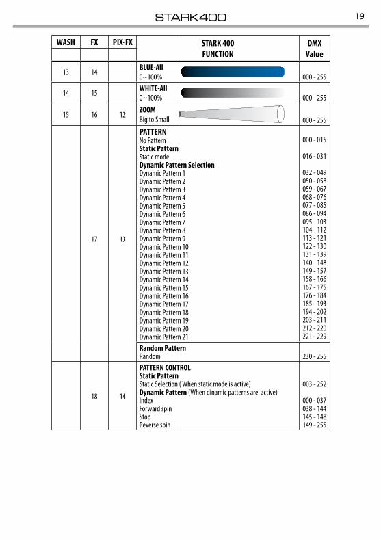
13 14 BLUE-All 0~100% 000 - 255
14 15 WHITE-All 0~100% 000 - 255
15 16 12 ZOOMBig to Small 000 - 255
17 13
PATTERNNo PatternStatic PatternStatic modeDynamic Pattern SelectionDynamic Pattern 1Dynamic Pattern 2Dynamic Pattern 3Dynamic Pattern 4Dynamic Pattern 5Dynamic Pattern 6Dynamic Pattern 7Dynamic Pattern 8Dynamic Pattern 9Dynamic Pattern 10 Dynamic Pattern 11Dynamic Pattern 12Dynamic Pattern 13Dynamic Pattern 14Dynamic Pattern 15Dynamic Pattern 16Dynamic Pattern 17Dynamic Pattern 18Dynamic Pattern 19Dynamic Pattern 20Dynamic Pattern 21
000 - 015
016 - 031
032 - 049050 - 058059 - 067068 - 076077 - 085086 - 094095 - 103104 - 112113 - 121122 - 130131 - 139140 - 148149 - 157158 - 166167 - 175176 - 184185 - 193194 - 202203 - 211212 - 220221 - 229
Random PatternRandom 230 - 255
18 14
PATTERN CONTROLStatic PatternStatic Selection ( When static mode is active)Dynamic Pattern (When dinamic patterns are active)Index Forward spinStopReverse spin
003 - 252
000 - 037038 - 144145 - 148149 - 255
STARK40020
WASH FX PIX-FX STARK 400FUNCTION
DMXValue
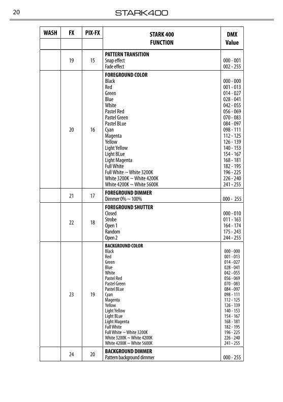
19 15PATTERN TRANSITIONSnap effectFade effect
000 - 001 002 - 255
20 16
FOREGROUND COLORBlackRedGreenBlueWhitePastel RedPastel GreenPastel BLueCyanMagentaYellowLight YellowLight BLueLight MagentaFull WhiteFull White ~ White 3200KWhite 3200K ~ White 4200KWhite 4200K ~ White 5600K
000 - 000001 - 013014 - 027028 - 041042 - 055056 - 069070 - 083084 - 097098 - 111112 - 125126 - 139140 - 153154 - 167168 - 181182 - 195196 - 225226 - 240241 - 255
21 17 FOREGROUND DIMMERDimmer 0% ~ 100% 000 - 255
22 18
FOREGROUND SHUTTERClosedStrobeOpen 1RandomOpen 2
000 - 010011 - 163164 - 174175 - 243244 - 255
23 19
BACKGROUND COLORBlackRedGreenBlueWhitePastel RedPastel GreenPastel BLueCyanMagentaYellowLight YellowLight BLueLight MagentaFull WhiteFull White ~ White 3200KWhite 3200K ~ White 4200KWhite 4200K ~ White 5600K
000 - 000001 - 013014 - 027028 - 041042 - 055056 - 069070 - 083084 - 097098 - 111112 - 125126 - 139140 - 153154 - 167168 - 181182 - 195196 - 225226 - 240241 - 255
24 20 BACKGROUND DIMMERPattern background dimmer 000 - 255
21STARK400
WASH FX PIX-FX STARK 400FUNCTION
DMXValue
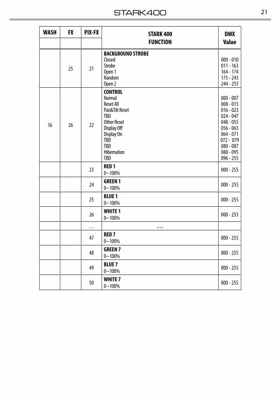
25 21
BACKGROUND STROBEClosedStrobeOpen 1RandomOpen 2
000 - 010011 - 163164 - 174175 - 243244 - 255
16 26 22
CONTROLNormalReset AllPan&Tilt ResetTBDOther ResetDisplay OffDisplay On TBDTBDHibernationTBD
000 - 007008 - 015016 - 023024 - 047048 - 055056 - 063064 - 071072 - 079080 - 087088 - 095096 - 255
23 RED 10~100% 000 - 255
24 GREEN 10~100% 000 - 255
25 BLUE 10~100% 000 - 255
26 WHITE 10~100% 000 - 255
. . . . . .
47 RED 70~100% 000 - 255
48 GREEN 70~100% 000 - 255
49 BLUE 70~100% 000 - 255
50 WHITE 70~100% 000 - 255
STARK40022
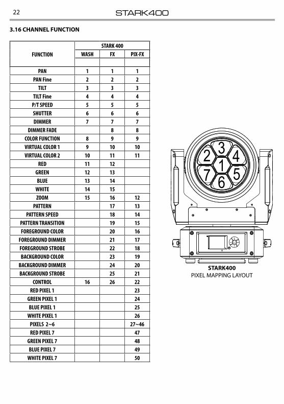
3.16 CHANNEL FUNCTION
12 3 4567
ENTER
STARK400PIXEL MAPPING LAYOUT
FUNCTION STARK 400
WASH FX PIX-FX
PAN 1 1 1PAN Fine 2 2 2
TILT 3 3 3TILT Fine 4 4 4
P/T SPEED 5 5 5SHUTTER 6 6 6DIMMER 7 7 7
DIMMER FADE 8 8COLOR FUNCTION 8 9 9VIRTUAL COLOR 1 9 10 10VIRTUAL COLOR 2 10 11 11
RED 11 12GREEN 12 13BLUE 13 14
WHITE 14 15ZOOM 15 16 12
PATTERN 17 13PATTERN SPEED 18 14
PATTERN TRANSITION 19 15FOREGROUND COLOR 20 16
FOREGROUND DIMMER 21 17FOREGROUND STROBE 22 18BACKGROUND COLOR 23 19
BACKGROUND DIMMER 24 20BACKGROUND STROBE 25 21
CONTROL 16 26 22RED PIXEL 1 23
GREEN PIXEL 1 24BLUE PIXEL 1 25
WHITE PIXEL 1 26PIXELS 2~6 27~46RED PIXEL 7 47
GREEN PIXEL 7 48BLUE PIXEL 7 49
WHITE PIXEL 7 50
23STARK400
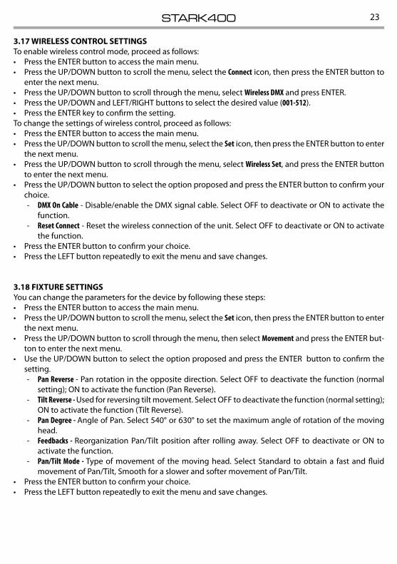
3.17 WIRELESS CONTROL SETTINGSTo enable wireless control mode, proceed as follows:• Press the ENTER button to access the main menu.• Press the UP/DOWN button to scroll the menu, select the Connect icon, then press the ENTER button to
enter the next menu.• Press the UP/DOWN button to scroll through the menu, select Wireless DMX and press ENTER.• Press the UP/DOWN and LEFT/RIGHT buttons to select the desired value (001-512).• Press the ENTER key to confirm the setting.To change the settings of wireless control, proceed as follows:• Press the ENTER button to access the main menu.• Press the UP/DOWN button to scroll the menu, select the Set icon, then press the ENTER button to enter
the next menu.• Press the UP/DOWN button to scroll through the menu, select Wireless Set, and press the ENTER button
to enter the next menu.• Press the UP/DOWN button to select the option proposed and press the ENTER button to confirm your
choice. - DMX On Cable - Disable/enable the DMX signal cable. Select OFF to deactivate or ON to activate the
function. - Reset Connect - Reset the wireless connection of the unit. Select OFF to deactivate or ON to activate
the function.• Press the ENTER button to confirm your choice.• Press the LEFT button repeatedly to exit the menu and save changes.
3.18 FIXTURE SETTINGSYou can change the parameters for the device by following these steps:• Press the ENTER button to access the main menu.• Press the UP/DOWN button to scroll the menu, select the Set icon, then press the ENTER button to enter
the next menu.• Press the UP/DOWN button to scroll through the menu, then select Movement and press the ENTER but-
ton to enter the next menu.• Use the UP/DOWN button to select the option proposed and press the ENTER button to confirm the
setting. - Pan Reverse - Pan rotation in the opposite direction. Select OFF to deactivate the function (normal
setting); ON to activate the function (Pan Reverse). - Tilt Reverse - Used for reversing tilt movement. Select OFF to deactivate the function (normal setting);
ON to activate the function (Tilt Reverse). - Pan Degree - Angle of Pan. Select 540° or 630° to set the maximum angle of rotation of the moving
head. - Feedbacks - Reorganization Pan/Tilt position after rolling away. Select OFF to deactivate or ON to
activate the function. - Pan/Tilt Mode - Type of movement of the moving head. Select Standard to obtain a fast and fluid
movement of Pan/Tilt, Smooth for a slower and softer movement of Pan/Tilt.• Press the ENTER button to confirm your choice.• Press the LEFT button repeatedly to exit the menu and save changes.
STARK40024
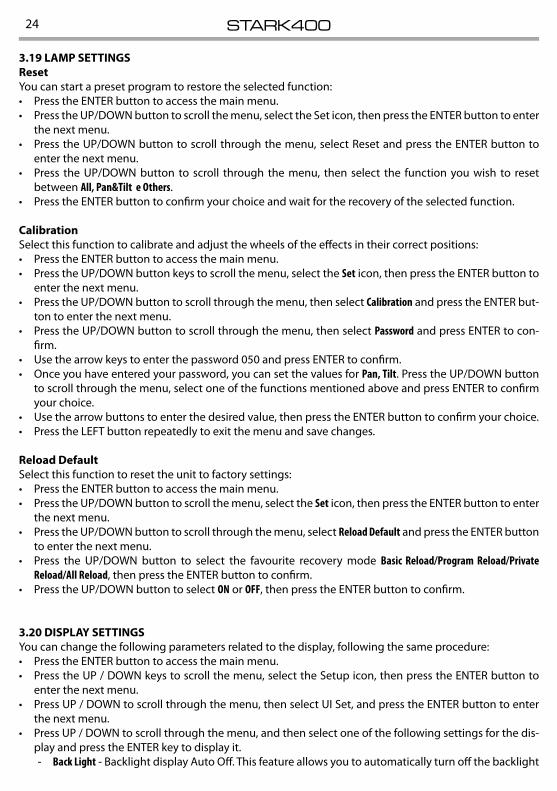
3.19 LAMP SETTINGSResetYou can start a preset program to restore the selected function:• Press the ENTER button to access the main menu.• Press the UP/DOWN button to scroll the menu, select the Set icon, then press the ENTER button to enter
the next menu.• Press the UP/DOWN button to scroll through the menu, select Reset and press the ENTER button to
enter the next menu.• Press the UP/DOWN button to scroll through the menu, then select the function you wish to reset
between All, Pan&Tilt e Others.• Press the ENTER button to confirm your choice and wait for the recovery of the selected function.
CalibrationSelect this function to calibrate and adjust the wheels of the effects in their correct positions:• Press the ENTER button to access the main menu.• Press the UP/DOWN button keys to scroll the menu, select the Set icon, then press the ENTER button to
enter the next menu.• Press the UP/DOWN button to scroll through the menu, then select Calibration and press the ENTER but-
ton to enter the next menu.• Press the UP/DOWN button to scroll through the menu, then select Password and press ENTER to con-
firm.• Use the arrow keys to enter the password 050 and press ENTER to confirm.• Once you have entered your password, you can set the values for Pan, Tilt. Press the UP/DOWN button
to scroll through the menu, select one of the functions mentioned above and press ENTER to confirm your choice.
• Use the arrow buttons to enter the desired value, then press the ENTER button to confirm your choice.• Press the LEFT button repeatedly to exit the menu and save changes.
Reload DefaultSelect this function to reset the unit to factory settings:• Press the ENTER button to access the main menu.• Press the UP/DOWN button to scroll the menu, select the Set icon, then press the ENTER button to enter
the next menu.• Press the UP/DOWN button to scroll through the menu, select Reload Default and press the ENTER button
to enter the next menu.• Press the UP/DOWN button to select the favourite recovery mode Basic Reload/Program Reload/ Private
Reload/All Reload, then press the ENTER button to confirm.• Press the UP/DOWN button to select ON or OFF, then press the ENTER button to confirm.
3.20 DISPLAY SETTINGSYou can change the following parameters related to the display, following the same procedure:• Press the ENTER button to access the main menu.• Press the UP / DOWN keys to scroll the menu, select the Setup icon, then press the ENTER button to
enter the next menu.• Press UP / DOWN to scroll through the menu, then select UI Set, and press the ENTER button to enter
the next menu.• Press UP / DOWN to scroll through the menu, and then select one of the following settings for the dis-
play and press the ENTER key to display it. - Back Light - Backlight display Auto Off. This feature allows you to automatically turn off the backlight
25STARK400
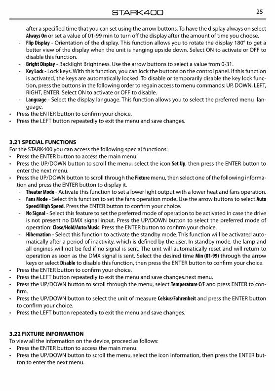
after a specified time that you can set using the arrow buttons. To have the display always on select Always On or set a value of 01-99 min to turn off the display after the amount of time you choose.
- Flip Display - Orientation of the display. This function allows you to rotate the display 180° to get a better view of the display when the unit is hanging upside down. Select ON to activate or OFF to disable this function.
- Bright Display - Backlight Brightness. Use the arrow buttons to select a value from 0-31. - Key Lock - Lock keys. With this function, you can lock the buttons on the control panel. If this function
is activated, the keys are automatically locked. To disable or temporarily disable the key lock func-tion, press the buttons in the following order to regain access to menu commands: UP, DOWN, LEFT, RIGHT, ENTER. Select ON to activate or OFF to disable.
- Language - Select the display language. This function allows you to select the preferred menu lan-guage.
• Press the ENTER button to confirm your choice.• Press the LEFT button repeatedly to exit the menu and save changes.
3.21 SPECIAL FUNCTIONSFor the STARK400 you can access the following special functions:• Press the ENTER button to access the main menu.• Press the UP/DOWN button to scroll the menu, select the icon Set Up, then press the ENTER button to
enter the next menu.• Press the UP/DOWN button to scroll through the Fixture menu, then select one of the following informa-
tion and press the ENTER button to display it. - Theater Mode - Activate this function to set a lower light output with a lower heat and fans operation. - Fans Mode - Select this function to set the fans operation mode. Use the arrow buttons to select Auto
Speed /High Speed. Press the ENTER button to confirm your choice. - No Signal - Select this feature to set the preferred mode of operation to be activated in case the drive
is not present no DMX signal input. Press the UP/DOWN button to select the preferred mode of operation: Close/Hold/Auto/Music. Press the ENTER button to confirm your choice.
- Hibernation - Select this function to activate the standby mode. This function will be activated auto-matically after a period of inactivity, which is defined by the user. In standby mode, the lamp and all engines will not be fed if no signal is sent. The unit will automatically reset and will return to operation as soon as the DMX signal is sent. Select the desired time Min (01-99) through the arrow keys or select Disable to disable this function, then press the ENTER button to confirm your choice.
• Press the ENTER button to confirm your choice.• Press the LEFT button repeatedly to exit the menu and save changes.next menu.• Press the UP/DOWN button to scroll through the menu, select Temperature C/F and press ENTER to con-
firm.• Press the UP/DOWN button to select the unit of measure Celsius/Fahrenheit and press the ENTER button
to confirm your choice.• Press the LEFT button repeatedly to exit the menu and save changes.
3.22 FIXTURE INFORMATIONTo view all the information on the device, proceed as follows:• Press the ENTER button to access the main menu.• Press the UP/DOWN button to scroll the menu, select the icon Information, then press the ENTER but-
ton to enter the next menu.
STARK40026
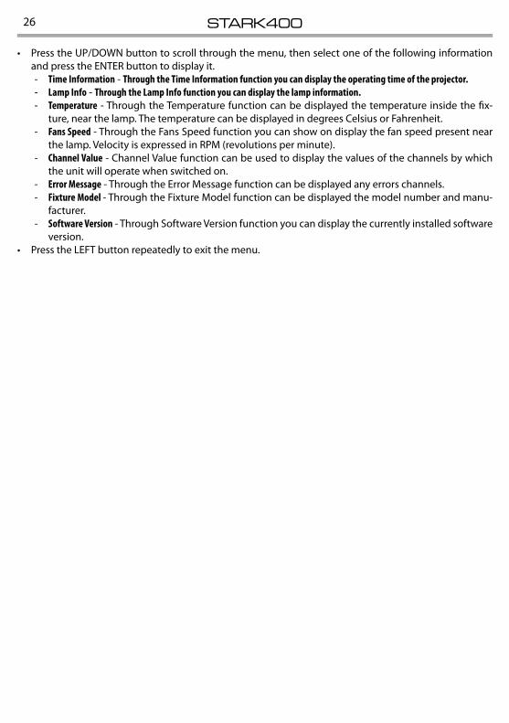
• Press the UP/DOWN button to scroll through the menu, then select one of the following information and press the ENTER button to display it.
- Time Information - Through the Time Information function you can display the operating time of the projector. - Lamp Info - Through the Lamp Info function you can display the lamp information. - Temperature - Through the Temperature function can be displayed the temperature inside the fix-
ture, near the lamp. The temperature can be displayed in degrees Celsius or Fahrenheit. - Fans Speed - Through the Fans Speed function you can show on display the fan speed present near
the lamp. Velocity is expressed in RPM (revolutions per minute). - Channel Value - Channel Value function can be used to display the values of the channels by which
the unit will operate when switched on. - Error Message - Through the Error Message function can be displayed any errors channels. - Fixture Model - Through the Fixture Model function can be displayed the model number and manu-
facturer. - Software Version - Through Software Version function you can display the currently installed software
version.• Press the LEFT button repeatedly to exit the menu.
27STARK400
- 4 - MAINTENANCE
4.1 MAINTENANCE AND CLEANING THE UNIT• Make sure the area below the installation place is free from unwanted persons during setup.• Switch off the unit, unplug the main cable and wait until the unit has cooled down.• All screws used for installing the device and any of its parts should be tightly fastened and should not
be corroded.• Housings, fixations and installation spots (ceiling, trusses, suspensions) should be totally free from any
deformation.• When the lens is visibly damaged due to cracks or deep scratches, it must be replaced.• The main cables must be in impeccable condition and should be replaced immediately even when a
small problem is detected.• In order to protect the device from overheating the cooling fans (if any), and ventilation openings
should be cleaned monthly.To ensure optimal operation and performance for a long time it is essential to periodically clean the parts subject to dust and grease deposits. The frequency with which the following operations are to be carried out depends on various factors, such as the amount of the effects and the quality of the working environ-ment (air humidity, presence of dust, salinity, etc.). Use a soft cloth dampened with any detergent liquid for cleaning glass to remove the dirt from the reflectors, from the lenses and filters.It is recommended that the projector undergoes an annual service by a qualified technician for special maintenance involving at least the following operations:
- General cleaning of internal parts.. - Restoring lubrication of all parts subject to friction, using lubricants specifically. - General visual check of the internal components, cabling, mechanical parts, etc. - Electrical, photometric and functional checks; eventual repairs.
Warning: we strongly recommend internal cleaning to be carried out by qualified personnel!
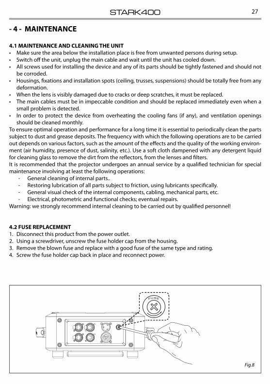
4.2 FUSE REPLACEMENT1. Disconnect this product from the power outlet.2. Using a screwdriver, unscrew the fuse holder cap from the housing.3. Remove the blown fuse and replace with a good fuse of the same type and rating.4. Screw the fuse holder cap back in place and reconnect power.
Fig.8
STARK40028
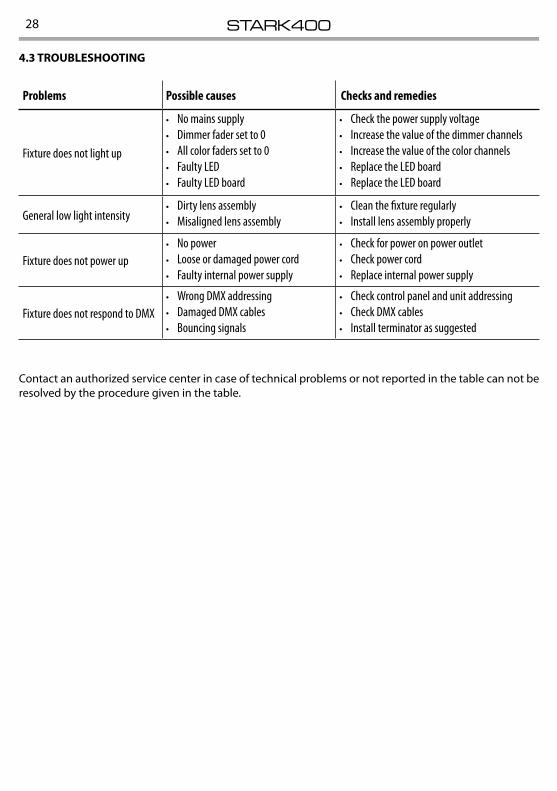
4.3 TROUBLESHOOTING
Problems Possible causes Checks and remedies
Fixture does not light up
• No mains supply• Dimmer fader set to 0• All color faders set to 0• Faulty LED• Faulty LED board
• Check the power supply voltage• Increase the value of the dimmer channels• Increase the value of the color channels• Replace the LED board• Replace the LED board
General low light intensity• Dirty lens assembly• Misaligned lens assembly
• Clean the fixture regularly• Install lens assembly properly
Fixture does not power up• No power• Loose or damaged power cord• Faulty internal power supply
• Check for power on power outlet• Check power cord• Replace internal power supply
Fixture does not respond to DMX• Wrong DMX addressing• Damaged DMX cables• Bouncing signals
• Check control panel and unit addressing• Check DMX cables• Install terminator as suggested
Contact an authorized service center in case of technical problems or not reported in the table can not be resolved by the procedure given in the table.

29STARK400