72
STARPLUS 616ex Electronic Key System

STARPLUS
616ex
Electronic Key System

STARPLUS 616EX ISSUE 2 JULY I,1987
TABLE OF CONTENTS
SECTION 100 INTRODUCTION PAGE 100.1 PURPOSE..............................................l-l 100.2 REGULATORY INFORMATION (FCC) . . . . . . . . . . . . . . l-l
SECTION 200
200.1 200.2 200.3 200.4
GENERAL DESCRIPTION
TECHNOLOGY..........................................2- 1 CAPAClTY..............................................2- 2 SYSTEM COMPONENTS ................................ .2-2 SYSTEM SPECIFICATIONS. .............................. .2-3
SECTION 300
300.1
FEATURE DESCRIPTION
ALPHABETICAL LISTING OF FEATURES. . . . . .3-2
SECTION 400 400.1 400.2 400.3 400.4 400.5 400.6 400.7 400.8 400.9 400.10 400.11 400.12 400.13 400.14 400.15 400.16 400.17 400.18
INSTALLATION
SITE PLANNING ........................................ .4-l UNPACKING THE 616EX KSU ........................... .4-l KSU GROUNDlNG.......................................4- 1 KSU INSTALLATION ..................................... .4-l KSU CABLING ......................................... .4-2 LIGHTNING PROTECTION ................................ 4-2 KEY TELEPHONE INSTALLATION ......................... .4-2 WALL MOUNT KIT INSTALLATION ........................ .4-2 PHONE BOX INSTALLATION .............................. 4-3 EXTERNAL MUSIC SOURCE .............................. 4-3 ALARM INSTALLATION ................................... 4-3 BAlTERY BACK-UP. ..................................... 4-3 EXTERNAL PAGING. ..................................... 4-7 LOUD BELL CONTROL. .................................. 4-7 EMERGENCY TRANSFER ................................ 4-7 HEADSET INSTALLATION. ................................ 4-7 MINI PRINTER INSTALLATION. ............................ 4-8 INSTALLATION AND POWER-UP CHECKLIST ............... 4-8
I
STARPLUS 6’16EX ISSUE 2 JULY I,1987
SECTION 500
500.1 500.2 500.3 500.4 500.5 500.6 500.7 500.8 500.9 500.10 500.11 500.12 500.13 500.14 500.15 500.16 500.17 500.18 500.19 500.20 500.21 500.22 500.23 500.24 500.25 500.26 500.27 500.28 500.29 500.30 500.31 500.32 500.33
SECTION 600
600.1 600.2 600.3 600.4
CUSTOMER DATA BASE PROGRAMMING PAGE
INTRODUCTION ........................................ 5-l CUSTOMER DATA WORKSHEET ......................... 5-2 DATA BASE FIELDS. .................................... 5-2 PROGRAM MODE ENTRY ............................... 5-2 SYSTEM INITIALIZATION. ................................ 5-2 STATION CLASS OF SERVICE. .......................... 5-4 STATION DATA ......................................... 5-4 STA ASSIGNMENTS .................................... 5-5 CO LINE ACCESS. ..................................... 5-6 PAGINGGROUP.. ..................................... 5-6 CO LINE GROUPS. ..................................... 5-6 CO LINE PROGRAMMING ............................... 5-7 CO LINE RINGING- DAY ................................ 5-7 CO LINE RINGING - NIGHT .............................. 5-8 FLASH TIMER ......................................... 5-8 CO RING DETECT. ..................................... 5-8 DIAL PULSE. .......................................... 5-8 SYSTEM CONFIGURATION .............................. 5-10 SYSTEM TIMERS. ...................................... 5-l 1 EXECUTIVE/SECRETARY ASSIGNMENTS. ................. 5-l 2 LOUD BELL CONTROL. ................................. 5-l 2 PBX DIALING CODES ................................... 5-l 2 ATTENDANT POSITION ................................. 5- 12 CALL FORWARD PRESET ............................... 5-l 3 CONFERENCE TIMER .................................. 5-l 3 SMDR.. .............................................. 5-13 SMDRiBAUD RATE ..................................... 5-l 4 DATA BASE PRINTOUT. ................................. 5-l 4 TOLL RESTRICTION TABLES ............................ 5-l 7 STATION SPEED DIAL. .................................. 5-l 8 DIAL PULSE TO TONE SWITCHOVER. .................... 5-l 8 FLASH WITH SPEED DIAL ............................... 5-l 8 NIGHT SERVICE ....................................... 5-l 8
FUNCTIONAL TEST PROCEDURES
PRELIMINARY CHECKLIST .............................. 6-l KEY STATION TESTING ................................. 6-l INTERCOM FUNCTIONS TEST ........................... 6-3 CO LINE FUNCTIONS TEST. ............................. 6-5
II
STARPLUS 616EX ISSUE 2 JULY 1,1987
SECTION 700
700.1 700.2 700.3 700.4 700.5 700.6 700.7 700.8 700.9 700.10 700.11 700.12 700.13 700.14
MAINTENANCE AND TROUBLE SHOOTING
GENERAL INFORMATION. .................... INTRODUCTION. ............................ PREVENTIVE MAINTENANCE ................. TEST EQUIPMENT AND TOOLS ............... SPARE PARTS .............................. FIELD SERVICE ENGINEERING. ............... TROUBLE SHOOTING PROCEDURES .......... FAULT CLASSIFICATION ..................... SYSTEM FAILURE. .......................... POWER FAILURES .......................... KEY TELEPHONE FAILURES .................. CO/PBX LINE FAILURES. ..................... FEATURE OPERATION FAILURES ............. SUMMARY OF FAULT CONDITIONS ...........
INDEX OF FIGURES
FIGURE 1.1 FIGURE 1.2 FIGURE 2.1
FIGURE 2.2 FIGURE 2.3 FIGURE 4.1 FIGURE 4.2 FIGURE 4.3 FIGURE 4.4 FIGURE 5.1 FIGURE 7.1
STARPLUS KEY TELEPHONE. ................. STARPLUS KEY TELEPHONE. ................. STARPLUS 616 SYSTEM WITH ALL EXTERNAL CONNECTIONS .......... KEY SERVICE UNIT-LEFT SIDE ................ KEY SERVICE UNIT-RIGHT SIDE ............... TYPE 630 WALL MOUNT JACK. ............... PROCESSOR OR POWER FAILURE TRANSFER. EXTERNAL CONNECTIONS. ................... RS- 232C CONNECTIONS. .................... TOLL RESTRICTION FLOW CHART. ............ STARPLUS SYSTEM BLOCK DIAGRAM .........
.
. . .
. . . . . .
. . .
. . .
. .
. .
. . .
. . .
. . .
. .
. . .
.
.
.
. . . .
. . .
. . .
. . . . . . . .
. . . . .
. . . . .
7-l . 7-l . 7-1 . 7-1 . 7-1 . 7-l .7-l
7-l 7-2
. 7-2
. 7-2
. 7-2
. 7-2 7-4
PAGE
. . l-2
. . 1-3
. 2-7 . . 2-8 . . 2-9
. 4-l 1 . . 4-12 ’ 4-13 . .4-8
. .5-19
. . 7-3
STARPLUS 616EX ISSUE 2 JULY I,1987
INDEX OF TABLES
PAGE
TABLE 3-l TABLE 4-1 TABLE 4-2 TAGLE 4-3 TABLE 5-1 TABLE 5-2 TABLE 5-3 TAELE 5-4 TABLE 5-5 TABLE 7-l
FEATURE INDEX. ...................................... .3-l GEL-TYPE BAlTERY AMP. HOUR REQUIREMENTS. ......... 4-6 J-l CONNECTING BLOCK LAYOUT ....................... .4-9 J-2 CONNECTING BLOCK LAYOUT ........................ 4-10 DATA FIELDS AND DEFAULT VALUES ..................... .5-3 ACCESS AND RINGING - DAY. ........................... .5-9 ACCESS AND RINGING - NIGHT. ................. : ....... .5-9 NUMBERING PLAN ..................................... .5-l 8 DATA BASE PRINTOUT. .................................. 5-l 5 POWER TEST. ......................................... .7-l 4
IV
STARPLUS 616EX ISSUE 2 JULY I,1987
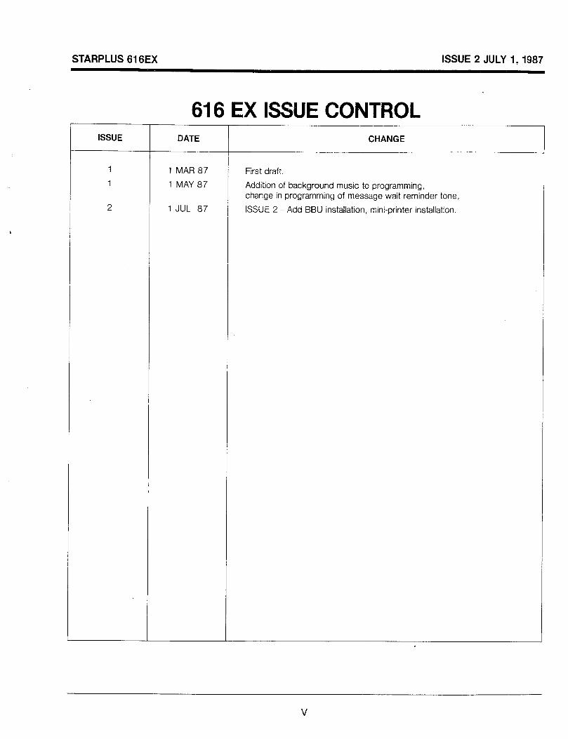
616 EX ISWE CONTROL ISSUE DATE CHANGE
1 MAR 87 First draft.
1 MAY 87 Addition of background music to programming, change in programming of message wait reminder tone,
1 JUL 87 ISSUE 2 - Add BBU installation, mini-printer installation.

STARPLUS 616EX ISSUE 2 JULY I,1987
100 INTRODUCTION
100.1. PURPOSE
This manual provides the information necessary to program, install, operate and maintain the STARPLUS 6 16EX Key Telephone System.
100.2 REGULATORY INFORMATION (FCC)
The Federal Communications Commission (FCC) has established rules which allow the direct connection of the STARPLUS 616EX Key Telephone System to the telephone network. Certain actions must be undertaken or understood before the connection of customer provided equipment is completed.
A.
B.
TELCO NOTIFICATION
Before connecting the STARPLUS 616EX Key Telephone System to the telephone network, the local serving telephone company must be given advance notice of intention to use customer provided equipment (CPE) and provided with the following information:
1.
2.
3.
4.
The telephone numbers to be connected to the system.
The FCC Registration Number located on the Key Service Unit (KSU). DLP82V-72088-KF-E
The Ringer Equivalence Number also located on the Key Service Unit (KSU). 0.2A
The USOC jack required for direct interconnection with the telephone network. RJl lC
INCIDENCE OF HARM
If the telephone company determines that the customer provided equipment (CPE) is faulty and possibly causing harm or interruption to the telephone network, it should be disconnected until repair can be effected. If this is not done, the telephone company may temporarily disconnect service.
C.
D.
E.
F.
CHANGES IN SERVICE
The local telephone company may make changes in its communications facilities or procedures. If these changes should affect the use of the 616EX or compatibility with the network, the the telephone company must give written notice to the user to allow uninterrupted service.
MAINTENANCE LIMITATIONS
Maintenance on the 616EX Key Telephone System is to be performed only by the manufacturer or its authorized agent. The user may may not make any changes and/or repairs except as specifically noted in this manual. If unauthorized alterations or repairs are performed, any remaining warranty may be voided.
NOTICE OF COMPLIANCE
The 616EX Key Telephone complies with rules regarding radiation and radio frequency emission by Class A computing devices. In accordance with FCC Standard 15 (Subpart J) the following information must be supplied to the end user:
“WARNING This equipment generates and uses R.F. energy, and if not installed and used in accordance with the Instruction Manual, it may cause interference to radio communications. It has been tested and found to comply with the limits for a Class A computing device, pursuant to Subpart J of Part 15 of the FCC Rules, which are designed to provide reasonable protection against such interference, when operated in a commercial environment. Operation of this equipment in a residential area is likely to cause interference, in which case the user, at his own expense, will be required to take whatever measures may be required to correct the interference.”
HEARING AID COMPATIBILITY The 616EX Key Telephone is Hearing Aid Compatible, as defined in Section 68.316 of Part 68 FCC Rules.
l-l

STARPLUS 616EX ISSUE 2 JULY I,1987
BASIC MODEL
ENHANCED
STARPLUS KEY TELEPHONE FIGURE 1.1
l-2

STARPLUS 616EX ISSUE 2 JULY I,1987
EXECUTIVE MODEb
‘
STARPLUS KEY TELEPHONE FIGURE 1.2
l-3
STARPLUS 616EX ISSUE 2 JULY 1, 1987
200 GENERAL DESCRIPTION
200.1 TECHNOLOGY
The STARPLUS 616EX Key Telephone System is a microprocessor controlled, solid state electronic switch which distributes communications in a non-blocking format. All control, switching and inter-face circuitry is condensed onto a single printed circuit board (PCB) located inside the key service unit (KSU).
Switching is accomplished through a solid state crosspoint matrix that provides voice path connecticns for six (6) central office lines, sixteen (16) key te!ephones and eight (8) intercom channels.
The central microprocessor is a Z-80 and controls the crosspoints and central office line relays. It also controls communications oetween slave microprocessors located in each key telephone.
The 616EX KSU contains all system memory which is composed of 16K of Read Only Memory (ROM) and 4K of Random Access Memory (RAM). The RAM is subdivided so that 2K is used 2.s CPU working area and 2K is used for customer data base The customer data base memory is protected from loss by a long life lithium battery. A Program Module contains the operating instructions for the system. This module can be easily removed and replaced which allows for upgrading software features.
The system power is regulated by a switching power supply. This technology provides high efficiency with low heat. A shielded transformer converts the 1 17 VAC into logic voltages on a separate power supply PCB, mounted within the KSU cabinet. Each key telephone contains a microprocessor and circuitry to monitor button activity and control lamp (LED) indications. A built in speaker permits voice or tone calling to the station. Executive and Enhanced model telephones have a Busy Lamp Field (BLF) to monitor station activity in the system.
Basic, Enhanced and Executive model key telephone sets are all equipped with eight (8) function buttons and six (6) CO line buttons. In addition Enhanced and Executive model phones are equipped with sixteen (16) Direct Station Selection (DSS) buttons and the Executive telephone is equipped with an LCD as standard equipment. A three-position slide switch is provided for easy selection of INTERCOM signaling modes, along with separate tone ringing and voice volume controls.
For emergency applications, a stand-alone battery assembly may be connected to the battery charging output terminals on the 6! 6EX KSU. This retains system power in the event of commercial power failure.
The system offers automatic cut-thru of central office lines to optionally provided single line telephones. These instruments can make and receive calls during a commercial AC power outage or following a CPU failure.
2-l
STARPLUS 616EX ISSUE 2 JULY 1,1987
200.2 CAPACITY
The 616EX Key Service Unit (KSU) is housed in a wall mountable cabinet that contains the Key Service Board (KSB), power supply and pre-wired connectors for station and CO line interface. The system comes fully configured for 6 CO lines, 16 key telephones and 8 intercom channels. One external page port provides two-way external paging capability. One loud bell control port offers programmable external signaling. One Music-On- Hold input allows connection of an external music source for MOH and background music. Separate MOH and background music adjustments are provided on the KSU. One alarm input allows connection of an external alarm or other sensing device. Low cost phone boxes may be substituted for key telephones on a one-for-one basis.
The sjlstem contains the necessary interface circuitry to enable complete system battery backup operation. In the event of commercial AC power interruption, a 24 volt DC battery assembly provided by the customer will ensure uninterrupted system operation. The battery support units must be provided separately.
200.3 SYSTEM COMPONENTS
The following are the components that make up the 616EX key telephone system:
The Basic KSU or the Enhanced KSU The Key Telephone
(Basic, Enhanced or Executive) Wall Mount Kit Program Module (I or II) Phone Box
616EX BASIC KSU
The KSU is a sealed, self contained unit that has no user-serviceable parts inside. All connections are made externally through amphenol-type plugs and screw terminal connections. A Program Module (I) allows easy expansion of software features.
616EX ENHANCED KSU
Uses Program Module II which provides Station Message Detail Recording and a Real Clock Unit. SMDR allows a customer to track incoming and/or outgoing, local and/or long distance calls by CO line, number dialed, time of day and date, station that placed the call, duration of the call and an account code. The Real Clock Unit provides Executive telephones with LCD to have time and date displayed and the time clock functioning in case of commercial power failure.
BASIC MODEL KEY TELEPHONE
Is a fully modular, multi-line keyset with voice and tone ringing volume controls. Contains 6 central office line buttons, 8 functions buttons, a dial pad and an intercom mode selection switch. All buttons are of the non locking type with easy to see LED’s for quick identification.
ENHANCED MODEL KEY TELEPHONE
Identical to the Basic Key Telephone with the addition of 16 Direct Station Select buttons and a speakerphone to provide full handsfree operation.
EXECUTIVE MODEL KEY TELEPHONE
Identical to the Enhanced Key Telephone with the addition of an interactive LED display. Displayed features include calls to and from other extensions, number dialed, line used, camp-on, etc.
WALL MOUNT KIT
Provides an attractive modular means of attaching the StarPlus key telephone to any vertical surface.
PHONE BOX
Allows handsfree conversations to and from locations that do not need dialing privileges. Phone boxes may be substituted for key stations on a one-for-one basis.
PROGRAM MODULE I
This plug in unit provides the instructions to the system giving feature and operating data.
PROGRAM MODULE II
Provides basic system operating instructions and in addition provides for Station Message Detail Recording and a Real Clock Unit.
2-2
STARPLUS 616EX ISSUE 2 JULY 1,1987
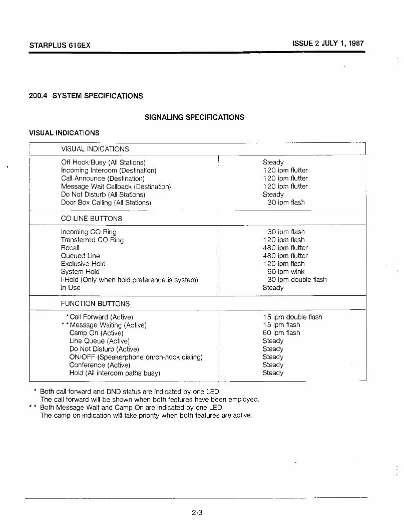
200.4 SYSTEM SPECIFICATIONS
SIGNALING SPECIFICATIONS
VISUAL INDICATIONS
VISUAL INDICATIONS
Off Hook’Busy (All Stations) Incoming Intercom (Destination) Call Announce (Destination) Message Wait Callback (Destination) Do Not Disturb (All Stations) Door Box Calling (All Stations)
Steady 120 ipm flutter 120 ipm flutter 120 ipm flutter Steady
30 ipm flash
CO LINE BUTTONS
Incoming CO Ring Transferred CO Ring Recall Queued Line Exclusive Hold System Hold I-Hold (Only when hold preference is system) In Use
FUNCTION BUTTONS
30 ipm flash 120 ipm flash 480 ipm flutter 480 ipm flutter 120 ipm flash
60 ipm wink 30 ipm double flash
Steady
l Call Forward (Active) * *Message Waiting (Active)
Camp On (Active) Line Queue (Active) Do Not Disturb (Active) ON/OFF (Speakerphone on/on-hook dialing) Conference (Active) Hold (All intercom paths busy)
15 ipm double flash 15 ipm flash 60 ipm flash Steady Steady Steady Steady Steady
l Both call forward and DND status are indicated by one LED. The call forward will be shown when both features have been employed.
l * Both Message Wait and Camp On are indicated by one LED. The camp on indication will take priority when both features are active.
2-3
STARPLUS 616EX ISSUE 2 JULY 1, 1987
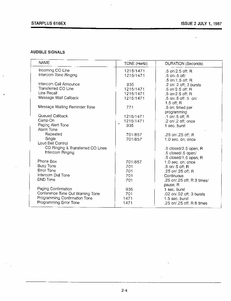
AUDIBLE SIGNALS
NAME
Incoming CO Line Intercom Tone Ringing
Intercom Call Announce Transferred CO Line Line Recall Message Wait Callback
Message Waiting Reminder Tone
Queued Callback Camp-On Paging Alert Tone Alarm Tone
Repeated Single
Loud Bell Control CO Ringing & Transferred CO Lines Intercom Ringing
Phone Box Busy Tone Error Tone Intercom Dial Tone DND Tone
Paging Confirmation Conference Time Out Warning Tone Programming Confirmation Tone Programming Error Tone
TONE (Hertz) DURATION (Seconds)
12151471 .5 oni2.5 off: R 1215/1471 .5 on.5 offi
.5 on/l .5 off; R 935 .2 on’.2 off; 3 bursts
121511471 .5 on’2.5 off: R 1215i1471 .5 oni2.5 off; R 121511471 .5 oni.5 off, .5 on/
1.5 off; R 771 .5 on; timed per
programming 1215/1471 .l on/.5 off; R 1215/1471 .2 or-V.2 off; once I
935 1 sec. burst
7011857 .25 on/.25 off; R 7011857 1 .O sec. on; once
.5 closed/2.5 open; R
.5 closed/.5 open/
.5 closed/l .5 open; R 701 /a57 1 .O sec. on; once 701 .5 on/.5 off; R 701 .25 on/.25 off; R 701 Continuous 701 .25 on/.25 off; R 3 times/
pause; R 935 1 sec. burst 701 .02 or-V.02 off; 3 bursts
1471 1.5 sec. burst 1471 .25 on/.25 off; R 6 times
2-4

STARPLUS 616EX ISSUE 2 JULY 1,1987
ELECTRICAL
,
t
AC Input to PS
Power Consumption Output Voltage
Station Cable Lengths (Maximum) (Twisted pair cable)
Battery Input Connector
Fuse - AC Input
Music Source (Input)
Contact Rating External Page Control Loud Bell Control Alarm
External Page Port Output Impedance Output Power
-,,,,,,,,u,. 60 Hz --/
70 WATTS 28 VDC, 0.5 A
800 ft. of 26 AWG Cable I 1200 ft. of 24 AWG Cable 1500 ft. of 22 AWG Cable / 24 V 0.7 A. 250 V 0.7 A. 250 V
2 K Ohms
1 .O A, 24 VDC 1 1 .O A, 24 VDC
600 Ohms @ 0 dBm 5 mW Maximum
ENVIRONMENTAL
Operating Temperature Optimum Humidity
32to122F 60 to 80 F 5% to 95% (non condensing)
2-5

STARPLUS 616EX ISSUE 2 JULY I,1987
DIALING
DTMF DIALING
Frequency Deviation Rise Time Duration of DTMF Signal Interdigit Time
PULSE DIALING
+ or - 1.5 Hz 5 msec.
70 msec. minimum 130 msec. minimum
Pulse Dialing Rate (programmable) Percent BreakMake (Programmable)
DIALING MEMORY
10to20pps 60140 to 66133
System Speed Dialing Station Speed Dialing Last Number Redial
CO Type
40 numbers (16 digit) any assigned station 10 numbers (16 digit) per key telephone
1 number (32 digit) per key telephone
Loop Start
DIMENSIONS AND WEIGHT
KEY SERVICE UNIT
Height Width Depth Weight
KEY TELEPHONE
22 inches 14 inches
2.5 inches 14 Ibs.
Height Width Depth Weight
PHONE BOX
3 inches 8 inches 9 inches 3 Ibs.
Height Width Depth Weight
1.75 inches 5.5 inches 4 inches 1 lb.
2-6

STARPLUS 616EX ISSUE 2 JULY 1,1987
- x- LLl= (I)=
m ‘DE - = III= Z.ZIZ = - Z
= - - = -
= -
r: a:
lllllll T lllllll I Illllll lllllll
II II -
- lllIllllII ; llIIllIllI 2 IIIIIIIIlll
IIIIIIlIlll
a g 2 v)
IIIIIIIIIIIIIII -7 IIIIIIIIIIIIIII IIIIIIIIIIIIIII
2-7

ISSUE 2 JULY I,1987
STARPLUS 616EX
MDF CON
P 0+
EXTERNAL _O Ill
BATERY BACK-UP CONNECTOR
616EX
LOWER MOUNTlNG BRACKETS
-PROGRAM MODULE
KEY SERVICE UNIT-LEFT SIDE FIGURE 2.2
2-8
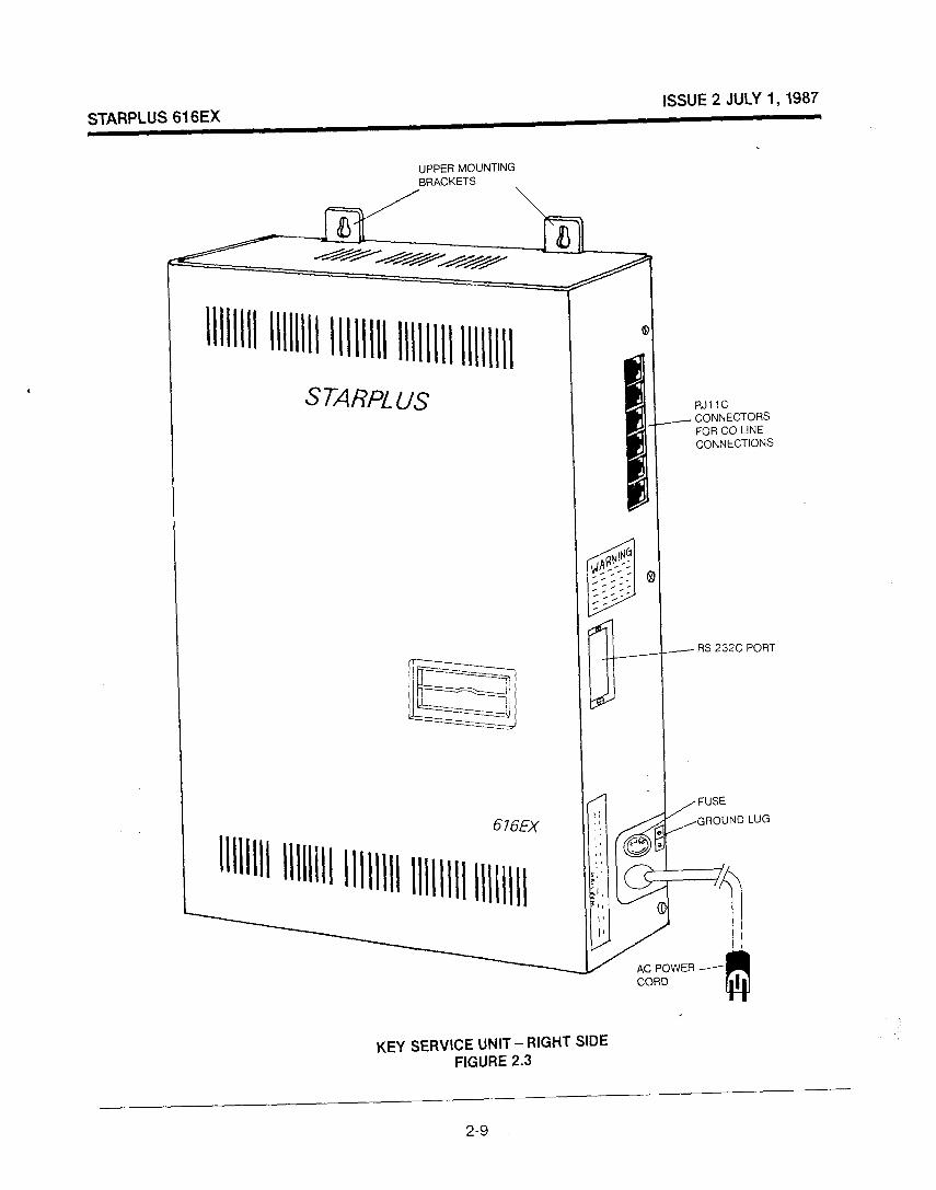
ISSUE 2 JULY I,1987
STARPLUS 616EX
lllllI llllllll 11111111 llllllll lllll
UppER MOUNTING BRACKETS
RJI 1C CONNECTORS FOR CO LINE CONNECTIONS
/ RS 232C PORT
/ FUSE
,GROUND LUG
KEY SERVICE UNIT - RIGHT SIDE FIGURE 2.3
2-9
STARPLUS 616EX ISSUE 2 JULY 1, 1987
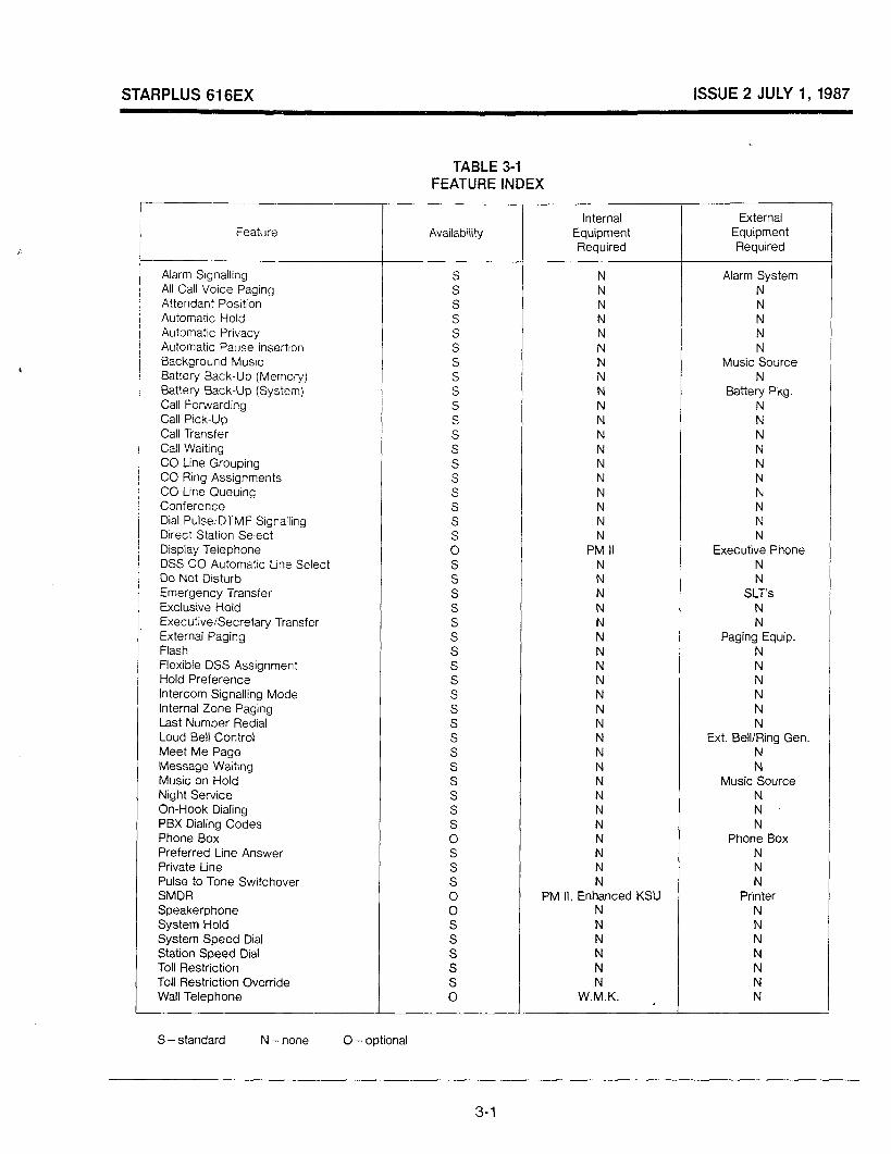
TABLE 3-l FEATURE INDEX
Feature Availability
Alarm Signalling S All Call Voice Paging S Attendant Position S Automatic Hold S Automatic Privacy S Automatic Pause Insertton S Background Music S Battery Back-Up (Memory) S Battery Back-Up (System) S Call Forwarding S Call Pick-Up S Call Transfer S Call Waiting S CO Line Grouping S CO Ring Assignments S CO Line Queuing S Conference S Dial Pulse. DTMF Srgnalling S Direct Station Select S Display Telephone 0 DSS CO Automatic Line Select S Do Not Drsturb S Emergency Transfer S Exclusive Hold S ExecutiveSecretary Transfer S External Paging S Flash S Flexible DSS Assignment S Hold Preference S Intercom Signalling Mode S Internal Zone Paging S last Number Redial S Loud Bell Control S Meet Me Page S Message Waiting S Music on Hold S Night Service S On-Hook Dialing S PBX Dialing Codes S Phone Box 0 Preferred Line Answer S Private Line S Pulse to Tone Switchover S SMDR 0 Speakerphone 0 System Hold S System Speed Dial S Station Speed Dial S Toll Restriction S Toll Restriction Override S Wall Telephone 0
Internal External Equipment Equipment Required Required
N Alarm System N N N N N N N N N N N Music Source N N N Battery Pkg. N N N N N N N N N N N N N N N N N N N N
PM II Executive Phone N N N N N SLT’s N N N N N Paging Equip. N N N N N N N N N N N N N Ext. Bell/Ring Gen. N N N N N Music Source N N N N N N N Phone Box N N N N N N
PM II, Enhanced KSU Printer N N N N N N N N N N N N
W.M.K. N
S - standard N - none 0 -optional
3-1
STARPLUS 616EX ISSUE 2 JULY I,1987
300 FEATURE DESCRIPTION
300.1 ALPHABETICAL LISTING OF FEATURES
ALARM SIGNALING
The system can recognize either an open or closed loop from an external relay and transmit an alarm signal. This signal can be sent to all available (non-busy) stations with either a continuous or single tone. The type of alarm tone is selected in system programming.
ALL CALL VOICE PAGING
Allowed stations may make voice paging announcements to all idle stations, phone boxes and external paging ports of the same time. Paging is a programmable feature and is assigned per station.
ATTENDANT POSITION
The system allows a.ny key telephone station to be assigned as the system attendant. The assigned s)lstem attendant WIII receive unattended line recalls and will initiate NIGt-lT SERVICE.
AUTOMATIC HOLD
Pressing a STATION or CONF key while on an outside line will automatically place the CO (outside) line on hold. This allows quick internal consultation and call transfer.
AUTOMATIC PRIVACY
Privacy is automatically provided on all communications in the system. If desired, the system may be programmed to eliminate privacy, allowing any station to join in on existing CO line conversations.
AUTOMATIC PAUSE INSERTION
If a flash is programmed into system and station speed dial numbers and save redial numbers, a pause will automatically be inserted after the flash. A pause will also be automatically inserted after a PBX dialing code has been used.
BACKGROUND MUSIC
Key telephones may receive music over their speaker when a music source has been connected to the system. The music can be turned on or off and the volume adjusted at each individual station. Maximum loudness level can be adjusted on the 616EX KSU.
BATTERY BACK-UP (MEMORY)
A long life lithium battery is provided in the KSU to retain the system data base in the event of a po’wer outage or the system power being turned off.
BATTERY BACK-UP (SYSTEM)
Optional maintenance free battenes and cabling can be directI\, connected to the STARPLUS 616EX KSU to provide full system operation in the event of a commercial power outage. Calls in progress will continue without interruption when the power fails. The batteries are recharged with an external battery charger when the system returns to normal AC operation.
CALLING STATION INDICATOR (BUSY Lamp Field)
Enhanced and Executive model key telephones are equipped with an LED indicator under each Direct Station Selection (DSS) button to indicate the status of the other keysets in the system.
CALL ANNOUNCING
A slide switch on the telephone allows users to select the way that calls to their phone are voice announced.
CALL FORWARDING-PRESET
System programming allows incoming CO lines, that are programmed to ring a particular station, to be forwarded to another predetermined station. This occurs when the station normally receiving the CO ring is busy or does not answer the call.
CALL PICKUP
Stations can be placed in one or both of 2 pickup groups. Stations within a group can pick up tone ringing intercom calls and recalling or transferred CO line calls for another station in that group.
CALL FORWARDING -STATION
Each key telephone user may direct intercom calls and transferred CO lines to be forwarded to another station in the system. A forwarded call will signal in the TONE mode regardless of the way the intercom signaling switch was set.
3-2
STARPLUS 616EX ISSUE 2 JULY I,1987
CALL TRANSFER
An outside CO line can be transferred from one keyset to another. By pressing the STATION button of the desired party, or pressing TRANS button and then dialing that station number. unscreened transfers or screened transfers with an announcement can be made. The line being transferred rungs on the keyset and gives a ftash indication to the receiving party’s keyset. Several attempts can be made to find someone at different keysets without losing the call. If a line is transferred to a busy station, it will receive muted ringing.
CAMP ON (CALL WAITING)
A station may alert a busy party that an outside line is on hold and waiting for them by use of the Call Waiting feature. To Camp-On a call, transfer the call to the desired busy station, then press the MSG CP.ON button twice. The called station will receive muted ring, hold flash indication on the waiting line. and a flashing “HOLD” button if the camp-on initiator is waiting to talk. The busy party can press the MSGICP.ON button, automatically placing his outside line on hold, to confer with the camp-on initiator. A station may camp-on another busy station without having a CO line connection, if desired. A CO line camped-on a station will recall the camp-on initiator if not picked up after the programmable period of time expires. Only the attendant station can camp-on to a station in the DND mode with a visual indication only. A camp-on cannot be made to a station in conference. The station designated “EXECUTIVE” in an ExecutiveSecretary pair can be camped-on only by the corresponding secretary.
CO LINE GROUPING
CO lines can be in one of up to six (6) groups to separate line types such as local, FX, PBX, etc. Stations are then individually assigned access to these lines and given the ability to dial on particular lines.
CO RING ASSIGNMENTS
CO lines are assigned to ring on a per-station basis according to system programming. Any station may be programmed to ring for any line(s) in the Day and/or during Night service.
CO LINE QUEUING
When CO lines are busy, stations can be placed on a list awaiting that CO line or a CO line in the same line group to become available. When a CO line becomes available, the system signals the waiting station. If the waiting station is busy when the queued CO line becomes available, the staton is placed at the bottom of the queue list. Three attempts will be made to reach a busy station before that station is dropped from the queue list. If a station doesn’t answer the que signal in 6 rings, that station will be dropped from the queue list.
CONFERENCE
A)
‘3
Multi-Line One (I ) internal station can engage in a conference with two (2) external parties. An external party can be dropped from the conference by pressing the CO line button of the party wishing to remain. The internal station may place the conference on HOLD by pressing the “HOLD” button.
Add-on Conference Two (2) internal stations can engage in conference with one (1) external party or 3 internal parties can set up a conferences. There is no limit on the number of add-on conferences, except for the total number of CO lines connected to the system.
COMMON AUDIBLE RINGING (LOUD BELL)
Incoming CO line ringing of a station can be directed to Loud Bell Control contacts. There is one (1) set of dry contacts that may be assigned to a station. An external power source and ringing device is required.
DIAL PULSElDTMF SIGNALING I . Each outside line can be individually programmed to provide dial pulse or tone sending.
DIAL PULSE TO TONE SWITCHOVER -
The signalling on a CO line can be changed from dial pulse to tone (DTMF). This allows dial pulse telephones to use common carriers which require DTMF signalling. This feature can also be stored and used with speed dial numbers.
3-3
STARPLUS 616EX ISSUE 2 JULY 1, 1987
DIRECT STATION SELECTION
Sixteen (16) buttons are dedicated at each Executive and Enhanced Key Telephone for immediate signalling and connection to other stations.
DSSlCO AUTOMATIC LINE SELECT
A DSS or CO line can be selected by pressing the associated button and automatically place the phone in the dialing mode. CO lines will bring up dial tone and DSS stations are automatically signalled.
DO NOT DISTURB (DND)
Placing a keyset in DND will eliminate incoming CO line ringing, intercom calls, CO line transfers, All Call Page announcements and Camp-Ons. The attendant position can override a station in DND, except for “executive” designated stations. The corresponding “secretary” can override the “executive” DND using the Camp-On feature. The station in DND can use the telephone to make normal outgoing calls. By programming, a station can be denied this feature.
EMERGENCY TRANSFER
In the event of commercial power failure or central processor failure, the system will automatically connect the first 3 CO lines to preconnected single line telephones.
EXCLUSIVE HOLD
A line placed on exclusive hold prohibits keysets from picking up a call held by another station.
EXECUTIVE/SECRETARY TRANSFER
Four (4) pairs of key telephones can be designated as executive/secretary. Whenever the “executive” phone is in DND or busy, transferred CO lines and intercom calls will be directed to the “secretary” station. If the secretary station is busy, busy tone will be received by the calling party.
There are three (3) combination types possible.
1 )Four (4) pairs of “Executive-Secretary” pools.
2)One (1) Executive with one-to-four Secretaries.
3)One (1) Secretary for one-to-four Executives.
EXTERNAL PAGING
Any station except one assigned as COS 6 can make voice paging announcements to the external paging port. Two way talkback paging is also possible
FLASH
The Flash button is used to re-establish dial tone or transfer a PBX call.
FLEXIBLE DSS (STA) ASSIGNMENT
The order of appearance of STA buttons assigned to telephones can be changed to meet customer needs.
HOLD PREFERENCE
This allows either exclusive hold or system hold to be the primary hold on the first depression of the hold button.
INCOMING INTERCOM MODE SELECTION
The key telephone user can select the method of receiving intercom calls at that station. A slide switch located on the telephone is used to select the mode. The choices are:
1)
2)
3)
Tone Ringer (T) A standard tone ring notifies the party of an incoming call. The party answers by lifting the handset.
Page (P) The station user receives a short tone burst and a voice announcement over the speaker. The microphone is deactivated, providing privacy. The person who is called must lift the handset to get the call or switch the selector to handsfree.
Handsfree (H) The station user, upon hearing a short tone burst and voice announcement over the integrated speaker, can reply handsfree. (Basic model key telephones do not have this feature.)
INTERNAL ZONE PAGE
Allowed stations can make voice paging announcements to idle stations in both internal zones at the same time or to either of the two internal zones.
3-4
STARPLUS 616EX ISSUE 2 JULY I,1987
LAST NUMBER REDIAL
The system automatically remembers the last number dialed even if the number was in speed dial. This number will be dialed over an outside line on command by the user.
MEET ME PAGE
Allows attendant or station users to call someone on the paging system. The called party then goes to the nearest telephone, dials a code and is connected to the calling party.
MESSAGE WAITING
A station user who calls another station and receives no answer can activate a “message waiting” lamp at that station to indicate this call. The station user who missed the call can then press his MSG/CP.ON button and ring the party leaving the message. Up to 5 messages may be left at each telephone.
MUSIC ON HOLD
An optional music source can be connected directly to the system to provide all held calls with music.
ON-HOOK DIALING
A telephone user who doesn’t have a speakerphone can place calls without lifting the handset, and monitor the call while the called party’s phone is ringing or on hold.
PBX DIALING CODES
Four 2 digit PBX access codes to be programmed into the system. When one of these codes is dialed, toll restriction will be applied at the digit dialed after the code was dialed. If one of the codes is not dialed, this indicates an intercom call and toll restriction does not apply. This allows the dialing of PBX extensions 100, 110, 111, etc.
NIGHT SERVICE
Attendant places system in night service by pressing DND button. CO lines will ring & can be answered according to system programming.
PHONE BOX
A phone box may be substituted for a telephone on a one for one basis. The phone box can be used to receive intercom announcements and also provide handsfree response. There is also a “call” button which will signal all stations programmed tc receive alarm ringing. (Data Field 02) One of these stations can respond to this signal by pressing the DSS button or dialing the intercom number of the phone box station. Two way conversation is then possible. The box is assigned a DSS button and when called, can respond handsfree to the call. A station can be programmed for door box by assigning COS 6 in station programming. (Data Field 01)
PREFERRED LINE ANSWER
A station with preferred line answer can answer any assigned ringing CO line by simply lifting the handset.
PRIVATE LINE
A line can be programmed as a private line. This line will be the only one to receive ringing and a flashing LED on that line. No other station can access this line. A private line can transfer calls to other stations. Night service will have no effect on these lines.
REAL TIME The system clock recording time and date is protected from commercial power failure to the system and continues to function. Available with Enhanced KSU & Program Module II only.
SPEAKERPHONE
Both Enhanced and Executive model telephones are equipped with a unit that enables the telephone to be used handsfree in two-way conversation.
STATION MESSAGE DETAIL RECORDING
An optional feature allowing the system to track both incoming and outgoing, local and long distance calls as determined in programming. It is also possible to print out data base programming with this module. Available with Enhanced KSU & Program Module II only.
3-5

STARPLUS 616EX ISSUE 2 JULY 1,1987
STATION SPEED DIAL
Each station can program 10 individual speed dial numbers of up to 16 digits in length. These numbers may contain pauses (#), with each 2 second pause taking up a digit. The numbers are dialed by going off-hook, pressing the SPEED button and dialing the bin number 00-09 where the number is stored.
SYSTEM SPEED DIAL 6
Forty (40) numbers can be programmed as system speed dial numbers. The numbers can be up to 16 digits in length, with pauses taking up digit space. The numbers are dialed by lifting the handset, pressing the SPEED button and dialing the 2 digit bin number (1 O-49). The last 20 speed dial bins are not monitored by toll restriction. The system speed numbers are entered at the programming station (station 01).
TOLL RESTRICTION
Each station in the system is programmed with a “class of service” level that defines the type of toll restriction that is assigned to that station.
VOLUME CONTROLS
Each keyset user can adjust both speaker and ring volume independently by using the two (2) volume controls located on the right side of the keyset.
WALL TELEPHONE
Any keyset can be adapted for wall mounting. The wall mount kit must be provided for wall mounting.
3-6

STARPLUS 616EX ISSUE 2 JULY I,1987
400 INSTALLATION
400.1 SITE PLANNING The STARPLUS 6 16EX Electronic Key Telephone System, like most electronic office equipment, should not be subjected to harsh environmental conditions. To assure easy servicing and reliable operation, several factors must be considered when planning the system installation. Always consider the following BEFORE installing the KSU and wiring:
4 B)
Cl ‘3
El
F) G)
HI
1)
The KSU is designed for wall-mounting only.
The internal power supply operates with 1 17 VAC, 60 Hz, single-phase electricity. A 3-wire (parallel blade with ground) receptacle must be provided on a dedicated, separately fused 15 AMP circuit.
Location(s) of telephone conduits or cable runs.
The KSU should be within 25 feet of the telephone company (TELCO) RJl 1 C. The KSU should be centrally located and assurances should be made to stay within prescribed cable lengths.
800 ft. 26 AWG Twisted pair Cable 1200 ft. 24 AWG Twisted pair Cable 1500 ft. 22 AWG Twisted pair Cable
A well ventilated area having a recommended temperature range of 60 to 80 degrees Fahrenheit, and a humidity range of 5 to 95% (non condensing).
Accessibility of KSU for servicing and lighting.
Protection from flooding, flammable materials, excessive dust and vibration.
Proximity of radio transmitting equipment, arc-welding devices, copying machines and other electrical equipment that are capable of generating electrical interferences.
Access to a good earth ground such as a metallic COLD water pipe. Inspect the pipe for non-metallic joints.
400.2 UNPACKING THE 616EX KSU
Remove the KSU from the shipping carton and place it on a level working surface, face up. Inspect the KSU for physical damage. The KSU has no serviceable parts.
400.3 KSU GROUNDING To ensure that the system will operate properly. a good earth ground is recommended. A metallic COLD water pipe will usually provide a reliable ground path. Carefully check that the pipe does not contain insulated joints that could isolate the ground. In the absence of the cold water pipe, a ground rod or other source may be used. A No. 8 AWG copper wire should be used between the ground source and the KSU.
THE GROUND WIRE SHOULD BE KEPT AS SHORT AS POSSIBLE AND CAN BE CONNECTED TO THE GROUND LUG LOCATED ON THE SIDE OF THE KSU. (Figure 2.3)
400.4 KSU INSTALLATION
A)
4
Cl
D)
The KSU is designed for wall mounting only. The KSU should NOT be mounted directly on a masonry surface.
If the KSU is to be mounted on a masonry surface, a wooden backboard of sufficient size should be attached to the wall and the KSU mounted on the backboard.
Mount the KSU on the backboard using four fasteners. (The fasteners should be selected carefully so as to be capable of supporting the KSU.) (Refer to Sec. 200.4 for KSU dimensions.)
Install the ground using an insulated 8 AWG copper wire. Attach one end to the grounding lug on the side of the KSU cabinet and fasten the other end to a good earth ground (Refer to Figure 2.3-KSU layout).
The KSU power supply is located within the KSU. Because the KSU is a sealed unit, all electrical connectiohs are provided externally. The power cord exits the KSU on the right side. Also on the right side is a fuse holder that contains a 0.7 Amp. slow-blow fuse. Power for the system is distributed internally (Refer to Figure 2.2 & 2.3). :
4-l
STARPLUS 616EX ISSUE 2 JULY 1,1987
El The power cord should not be used with a 3-wire-2-wire plug adapter. A power line surge protector should be used to protect the power supply from electrical surges. The surge protector should be installed in accordance with the manufacturer’s instructions and applicable local electrical codes.
WARNING: DO NOT PLUG IN THE POWER CORD AT THIS TIME.
400.5 KSU CABLING
Two (2) Amphenol-type connectors are provided on the left side of the KSU (Refer to Figure 2.2).
On the right edge of the front surface are the RJl 1 C connectors which are for CO lines. On the left side surface of the 616EX KSU are two connectors marked J-l and J-2. The J-l connector is located just below the J-2 connector. J-i and J-2 require 180 degree male ended plug cables for proper attachment. When connecting cable tails to the KSU, make sure the designation on the AMP hood matches the designation at the connector’s input on the KSU.
After plugging in the required cables, a “horse shoe” fastener should be placed around the mated AMP connectors to secure the cable to the KSU connector.
Verify that the wires are properly cross-connected. Observe the telephone standard wiring color codes whenever possible.
Some points to be aware of while running the key telephone cabling are: Cabling should be routed to avoid flourescent light fixtures, electric motors and generators, welding equipment and radio transmitters. Additionally, care should be taken to avoid hot locations such as steam pipes and furnaces, and areas where wiring is subject to abrasion.
CAUTION
It is NOT recommended that power be applied to the system during the cable termination process.
400.6 LIGHTNING PROTECTION
The 616EX should have central office lines protected with proper lightning surge arrestors. The central office lines are exposed to damaging surges induced by direct or non-direct lightning strikes.
The protection should contain a complement of 3-element gas discharge tubes which ground high potential surges, and associated circuits to absorb and filter lower-level surge potentials. Care should be taken to ensure that not more than one set of protectors be installed on central office lines at installtion premises, Improper installation of line protection can present a serious safety hazard.
400.7 KEY TELEPHONE INSTALLATION
A maximum of sixteen (16) key telephones may be installed with the 616EX Key System. Each key telephone requires 2 pair (4 wires) for proper wiring. It is recommended that 3 pair twisted pair cable be used to connect the telephones to the system on a “home run” basis. The telephone end of the cable should be terminated on a modular jack. At the MDF end of the home run, the cable should be terminated on a separate station connecting block (66Ml-50) for cross connection to the “J” cables. This method of cabling will allow for easy isolation of station equipment during trouble shooting procedures.
400.8 WALL MOUNT KIT INSTALLATION
All connections to the Key Telephones are fully modular. To wall mount the Key Telephone, it is necessary to have one Wall Mount Kit and one (1) 630-A type modular wall mount jack assembly equipped with two mounting lugs.
A)
W
C)
Remove the mounting cord from the telephone. This cord will no longer be needed.
Substitute the short modular cord on the wall mount baseplate for the mounting cord removed in A above.
Rotate the plastic number retainer upwards to expose the screw underneath. Remove the screw and slide the cover plate under the number retainer towards the hookswitch.
STARPLUS 616EX ISSUE 2 JULY I,1987
Q
El
F)
G)
Replace the cover plate with the handset retainer tab that is mounted in the wall mount base plate, and secure with the screw from C above.
Rotate the plastic number retainer downwards and snap into place.
Align the mounting tab on the outer edges of the wall mount base with the holes on the key telephone base. Snap shut and fasten with the screw.
The telephone can now be mounted to the wall by mating the two keyhole slots on the baseplate with the lugs on the modular cover assembly. Check to make sure that the modular connector on the baseplate has a firm connection with the connection on the wall jack. (Figure 4.1)
400.9 PHONE BOX INSTALLATION
The 6 16EX Phone Box can make calls to preassigned stations as well as receive intercom calls. The unit should be located in weather protected areas where paging or monitoring is required.
The Phone Box consists of a top housing and bottom mounting plate. The top housing has a speaker, mjcrophone, wire terminals and electronic circuitry. The housings are separated by inserting a thin, flat-edged tool at the bottom rim of the assembly. By pressing inwards on the recessed retaining tab, the assembly will open.
The connection of the Phone Box(es) to the KSU is identical to that of the key telephone. Refer to Sec. 400.6.
The bottom plate of the Phone Box assembly is fastened to the wall by mounting with customer supplied No. 8 or larger pan head screws. The cable is routed through the cable-entry holes provided on the bottom plate and is connected to the screw terminal strip on the upper housing. Four (4) screw terminals are identified by wire color on the silk- screened printed circuit board to correspond with the wiring sequence at the punchdown connector at the MDF.
The slack wiring should be pulled back through the bottom mounting plate and the top housing snapped shut. Refer to Sec. 500.6 (station class of service) to program phone boxes.
400.10 EXTERNAL MUSIC SOURCE
MUSIC-ON-HOLD, as well as BACKGROUND MUSIC can be connected using a customer provided tuner, tape deck, etc. Separate Music-on-Hold and background music volume adjustments are provided on the KSU. (Figure 2.3) Background Music (BGM) levels are also adjustable at each key telephone set. Connections are made on the J-l connector, the MOH pair. (Table 4-2)
If background music is desired, go to Section 500 (programming), Data Field 21 and enable background music.
400.11 ALARM INSTALLATION The 616EX system may be used to transmit an alarm signal to each station (except phone boxes) in the system. When activated by an external alarm system, a continuous tone is transmitted to the station speakers. Leads from the external alarm are connected to the 616 terminals ALMT and ALMR (Figure 4.3). See Section 500.7 for programming Alarm states. After the alarm has sounded, the system must be reset by first clearing the alarm condition on the external system and then lifting the handset at any station programmed to receive alarm and dialing 9.
400.12 BATTERY BACK-UP
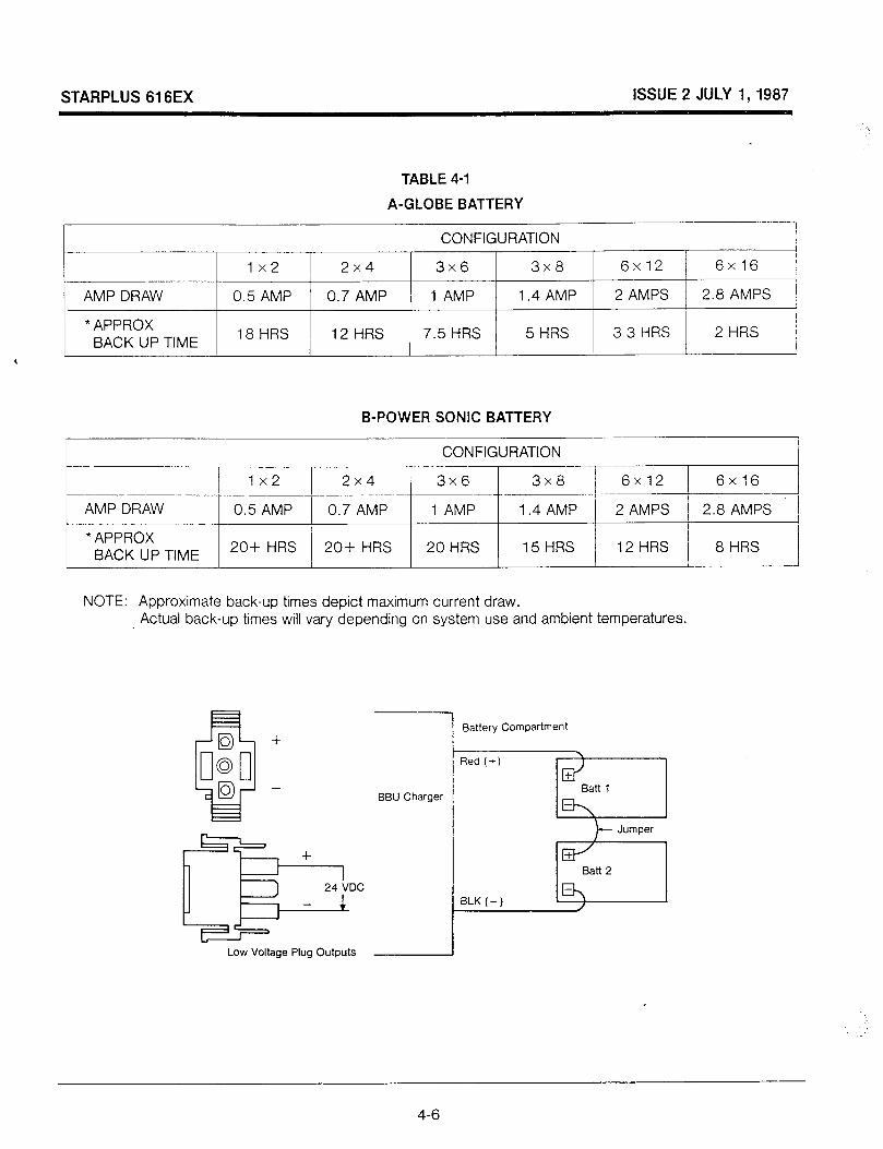
The STARPLUS 616EX can be fully supported for complete operation during a power failure. An externally provided 24 VDC battery package (gel type) and float charger is required. A convenient plug for battery connection is located on the left side of the KSU. (See Figure 2.2). Table 4-1 provides examples of recommended battery sizes for 2, 4 and 8 hour back-up at various system sizes.
4-3
STARPLUS 616EX ISSUE 2 JULY I,1987
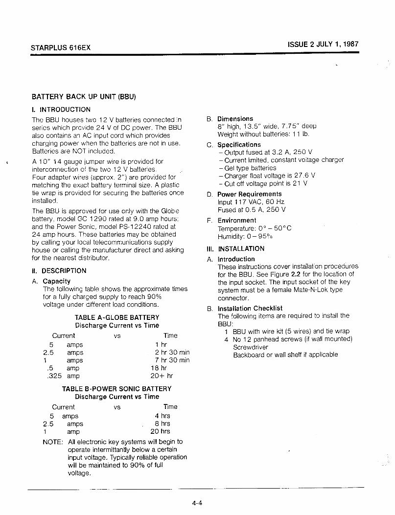
BATTERY BACK UP UNIT (BBU)
I. INTRODUCTION
The BBU houses two 12 V batteries connected in series which provide 24 V of DC power. The BBU also contains an AC input cord which provides charging power when the batteries are not in use. Batteries are NOT included.
6 A 10” 14 gauge jumper wire is provided for interconnection of the two 12 V batteries. Four adapter wires (approx. 2”) are provided for matching the exact battery terminal size. A plastic tie wrap is provided for securing the batteries once installed.
The BBU is approved for use only with the Globe battery, model GC 1290 rated at 9.0 amp hours; and the Power Sonic, model PS-12240 rated at 24 amp hours. These batteries may be obtained by calling your local telecommunications supply house or calling the manufacturer direct and asking for the nearest distributor.
II. DESCRIPTION
A. Capacity The following table shows the approximate times for a fully charged supply to reach 90% voltage under different load conditions.
TABLE A-GLOBE BATTERY Discharge Current vs Time
Current vs Time
5 amps 1 hr 2.5 amps 2 hr 30 min 1 amps 7 hr 30 min
.5 amp 18 hr
.325 amp 20+ hr
TABLE B-POWER SONIC BATTERY Discharge Current vs Time
Current vs Time
5 amps 4 hrs 2.5 amps 8 hrs 1 amp 20 hrs
NOTE: All electronic key systems will begin to operate intermittantly below a certain input voltage. Typically reliable operation will be maintained to 90% of full voltage.
B.
C.
D.
F.
Ill.
A.
B.
Dimensions 8” high, 13.5” wide, 7.75” deep Weight without batteries: 11 lb.
Specifications - Output fused at 3.2 A, 250 V - Current limited, constant voltage charger - Gel type batteries - Charger float voltage is 27.6 V - Cut off voltage point is 21 V
Power Requirements Input 117 VAC, 60 Hz Fused at 0.5 A, 250 V
Environment Temperature: 0’ - 50 o C Humidity: 0 - 95?b
INSTALLATION
Introduction These instructions cover installation procedures for the BBU. See Figure 2.2 for the location of the input socket. The input socket of the key system must be a female Mate-N-Lok type connector.
Installation Checklist The following items are required to install the BBU:
1 BBU with wire kit (5 wires) and tie wrap 4 No 12 panhead screws (if wall mounted)
Screwdriver Backboard or wall shelf if applicable
,
4-4

STARPLUS 616EX ISSUE 2 JULY I,1987
C. Mounting 1. The BBU must be located within 6’ of an AC
receptacle and 3’ of the KSU. 2. The BBU can be placed on a wall shelf or it
can be wall mounted. 3. To wall mount the BBU:
-The BBU is designed to be mounted on a backboard, either the backboard the KSU is mounted on or one specifically for the BBU.
- Mark for screw placement, either by measuring (the 2 top keyhole mounting slots are 8%” on center) or by placing the BBU against the backboard (before installing batteries) and marking the location of the 2 slots.
-Partially insert 2 No. 12 panhead sheet metal screws into the backboard.
- Suspend the BBU on these 2 screws. The large section of the keyhole will allow the unit to easily pass over the screwhead.
-Slowly lower the BBU so the small section of the keyhole is directly behind the screwhead.
-Tighten each screw so the unit fits snugly against the backboard.
- Insert 2 more screws into the bottom of the BBU where 2 more keyhole mounting slots are located.
D. Connections 1. Remove the BBU cover by turning the
4 screw locks and lifting the cover. 2. Install the two 12 V DC batteries in the
battery compartment. Thread the plastic tie wrap through the vent holes in the side of the battery compartment and fasten around both batteries. Cinch the tie wrap tight.
3. Connect one of the adapter wires to the black 10” jumper wire. Now install this jumper wire assembly between the NEG ( - ) terminal of battery 1 and the POS (+) terminal of battery 2.
4. Connect another adapter wire to the BBU red battery wire. Now connect this wire to the POS (+) terminal of battery 1.
5.
6.
7.
Connect the BBU black battery wire to the NEG (- ) terminal of Battery 2. Make sure the key system being connected is turned on. Then connect the BBU DC output cable to the battery input of the key system KSU. Make sure the BBU power switch is in the OFF position. Then plug in the AC power cord.
8. Turn the power switch on the BBU to ON.
Installation of the BBU is now complete.
IV. GENERAL INFORMATION
There is a “power on” LED which is lit when the supply is connected ta the AC power source. There is also a “battery” LED which is lit when the battery back up is in use. The BBU is a filtered battery back up power supply. Both input and output are fuse protected. The charger circuit is floating with respect to ground. The charging circuit provides a constant voltage and is current limited to 350 milliamps to the 2 gel cells.
V. MAINTENANCE
In order to ensure proper operation of the battery supply, the following operation should be performed once a month:
- Unplug the key system and the battery back up unit from the AC power to allow operation from the batteries for 15 minutes.
-Plug the key system and BBU power cord back into the AC outlet.
VI. TROUBLESHOOTING
When trouble is reported, verify that AC power is being supplied to the unit and that there are no blown fuses. Check the LED‘S TO SEE IF THEY are lit.
Assistance in trouble shooting is available from the factory. When calling you should have a VOM and a test set available and be calling from the job site. Call l-800-843-4863.
4-5
STARPLUS 616EX ISSUE 2 JULY 1,1987
TABLE 4-I
A-GLOBE BATTERY 1
CONFIGURATION
1x2 2x4 3x6 3x8 6x12 6x16 I
AMP DRAW 0.5 AMP 0.7 AMP 1 AMP 1.4 AMP 2 AMPS 2.8 AMPS /
* APPROX I BACK UP TIME 18 HRS 12 HRS 7.5 HRS 5 HRS 3.3 HRS 2 HRS j
I
B-POWER SONIC BATTERY
L CONFIGURATION
1x2 2x4 3x6 3x8 / - 6x12 6x16
1 4.- -_i
AMP DRAW 0.5 AMP 0.7 AMP 1 AMP 1.4 AMP 2 AMPS 2.8 AMPS t
l APPROX BACK UP TIME 20+ HRS 20+ HRS 20 HRS 15 HRS 12 HRS 8 HRS
NOTE: Approximate back-up times depict maximum current draw. Actual back-up times will vary depending on system use and ambient temperatures.
D + c 0 0 0 D - + CP 24 VDC
-
Low Voltage Plug Outputs
Battery Compartment
Red (+)
BLK (-)
d + Batt 1
D\
Jumper
+ cl Batt 2
-
4-6

STARPLUS 616EX ISSUE 2 JULY 1,1987
400.13 EXTERNAL PAGING
An amplifier for external paging may be connected to the 616EX Key Telephone System. Any telephone in the system can access this paging equipment by using a dial code. There is one (1) External Paging Zone (without amplifier) provided for in the 616EX System. Two way talkback paging is also possible. The output impedance of the paging zone is 600 Ohms at 0 d6m. The low level voice signal output is specified at 5 milliwatts. Dry contact control is provided to switch “ON” the external amplifier equipment or to momentarily remove background music, if externally supplied to the paging device. All connections are made on the J-l punchdown connector (Refer to Figure 4.3). The voice output from the Key Telephone System is provided on the EPVT & EPVR pair. The “make” contacts are identified as pair EPCTL. After connection is made to the paging port, DTMF tones are generated over the page port for an ancillary zone page unit.
400.14 LOUD BELL CONTROL
The 616EX system provides relay contact closure to activate external signaling equipment when an outside call rings in. The station that will receive this Loud Bell Control is selected in programming, data field 28.
The Loud Bell Control dry contacts will follow the assigned ringing of that station. Locate the LBCT nd LBCR terminals on the connecting block.
Connect two wires to these terminals and route them to a ringing generator or other power source provided by the customer.
All incoming CO lines assigned to ring at the station programmed to receive Loud Bell ringing will activate the Loud Bell Control, causing the LBC contacts to sequence in a .5 second ON/2.5 seconds OFF rate until all lines have been answered. The LBC contacts are current-rated at 1 Amp/24 VDC.
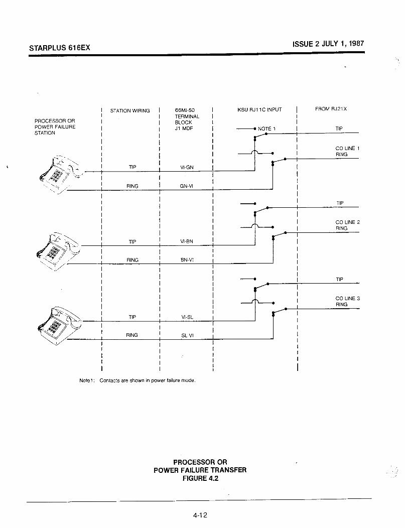
400.15 EMERGENCY TRANSFER
In the event of a commercial AC power interruption, the first three (3) CO/PBX lines will automatically transfer to single line telephones (if installed) for emergency communications. These SLT’s should be equipped with ringers. They can be DTMF type instruments or rotary dial. Connection is done on the Jl block, pairs 23, 24 and 25.
400.16 HEADSET INSTALLATION The STARPLUS Key Telephone has been designed to operate with industry standard modular headset adapters and operator headsets. To modify a Telephone to use an external headset, plug the headset adapter cord into the vacant handset jack on the key telephone base. Plug the telephone handset cord into the headset adapter box where indicated by the headset manufacturer’s instructions.
Then turn to the programming section of this manual, station configuration (data field 03). Enable the headset option for that particular station. Speakerphone operation is automatically disabled and such features as On Hook Dialing and Handsfree speakerphone are rendered inoperable. However, incoming page/voice announcements, tone ringing and background music will still be heard over the keyset speaker.
4-7
STARPLUS 616EX ISSUE 2 JULY 1,1987
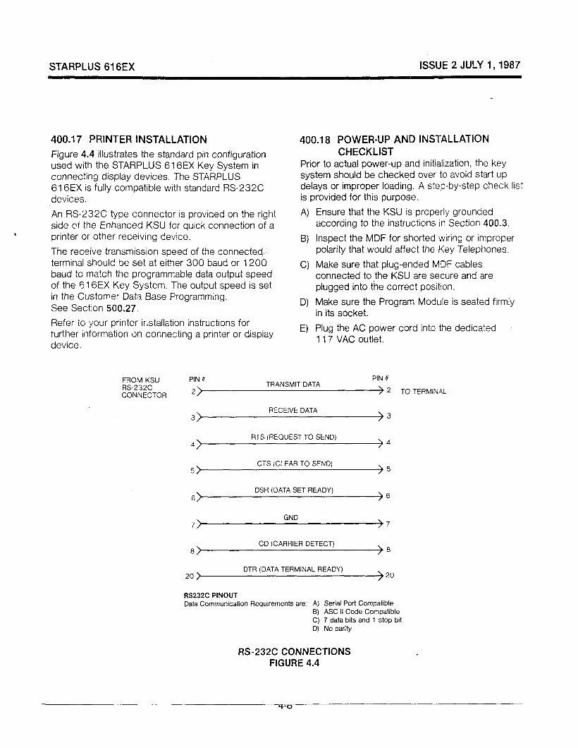
400.17 PRINTER INSTALLATION
Figure 4.4 illustrates the standard pin configuration used with the STARPLUS 616EX Key System in connecting display devices. The STARPLUS 616EX is fully compatible with standard RS-232C devices.
An RS-232C type connector is provided on the right side or the Enhanced KSU for quick connection of a
4 printer or other receiving device.
The receive transmission speed of the connected, terminal should be set at either 300 baud or 1200 baud to match the programmable data output speed of the 616EX Key System. The output speed is set in the Customer Data Base Programming. See Section 500.27.
Refer to your printer irstallation instructions for turther information on connecting a printer or dispiay device.
400.18 POWER-UP AND INSTALLATION CHECKLIST
Prior to actual power-up and initialization, the key system should be checked over to avoid start up delays or improper loading. A step-by-step check list is provided for this purpose.
A)
B)
Cl
D)
E)
Ensure that the KSU is properly grounded according to the instructions in Section 400.3.
Inspect the MDF for shorted wiring or improper polarity that would affect the Key Telephones.
Make sure that plug-ended MDF cables connected to the KSU are secure and are plugged into the correct position.
Make sure the Program Module is seated firmly in its socket.
Plug the AC power cord into the dedicated . 117 VAC outlet.
PIN #
2) TRANSMIT DATA
PIN #
> 2 TO TERMINAL
3) RECEIVE DATA
)3
FITS (REQUEST TO SEND) 4 >4
5) CTS (CLEAR TO SEND)
)5
6) DSR (DATA SET READY)
)6
7) GND
)7
8) CD (CARRIER DETECT)
)8
20 > DTR (DATA TERMINAL READY)
)20
RS232C PINOUT Data Communication Requirements are: A) Serial Port Compatible
5) ASC II Code Compatible C) 7 data bits and 1 stop bit D) No parity
RS-232C CONNECTIONS FIGURE 4.4

STARPLUS 616EX ISSUE 2 JULY 1, 1987
TABLE 4-2 J-l CONNECTING BLOCK LAYOUT
Station # Telephone tine Cord
GREEN
Station IO RED BLACK YELLOW
GREEN Station 11 RED
BLACK YELLOW
GREEN Station 12 RED
BLACK YELLOW
GREEN Station 13 RED
BLACK YELLOW
GREEN Station 14 RED
BLACK YELLOW
GREEN Station 15 RED
BLACK YELLOW
GREEN Station 16 RED
BLACK YELLOW
GREEN Station 17 RED
BLACK YELLOW
MUSIC-ON-HOLD
EXTERNAL PAGE (VOICE)
EXTERNAL PAGE DRY CONTACTS
ALARM
LOUD BELL CONTROL 1
POWER FAILURE 1
POWER FAILURE 2
POWER FAILURE 3
2 pr. Twisted Station Cable
WHIBL BUWH WHIOR ORIWH
WHlBL BUWH WHiOR OR/WH
WH/BL BUWH WHiOR ORIWH
WHIBL BL’WH WHIOR ORIWH
WHIBL BL’WH WHIOR ORIWH
WHIBL BUWH WHIOR ORiWH
WHiBL BL’WH WHIOR ORIWH
WHIBL BUWH WHIOR ORiWH
Function
VT1 VR 1 DT 1 DR 1
V-r2 VR 2 DT 2 DR 2
VT3 VR 3 DT 3 DR 3
V-r4 VR 4 DT 4 DR 4
VI-5 VR 5 DT 5 DR 5
VT6 VR 6 DT 6 DR 6
V-r7 VR 7 DT 7 DR 7
VT8 VR 8 DT 8 DR 8
MOH MOH
EPVT EPVR
EPCTL EPCTL
ALMT ALMR
LBClT LBClR
PFTl T PFTl R
PFT2T PFTPR
PFT3T PFT3R
MDF Connector Cable Pin
WHIBL 26 BL’WH 1 WHIOR 27 ORIWH 2
WHIGN 28 GNIWH 3 WHiBN 29 BNiWH 4
WHiSL 30 SL’WH 5 RDIBL 31 BL’RD 6
RDiOR 32 ORIRD 7 RDiGN 33 GNIRD 8
RDIBN 34. BNIRD 9 RD!SL 35 SL’RD 10
BWBL 36 BL’BK 11 BWOR 37 ORIBK 12
BWGN 38 GNlBK 13 BWBN 39 BNIBK 14
BWSL 40 SL’BK 15 YUBL 41 BUY L 16
YUOR 42 ORIYL 17
YL’GN 43 GNIYL 18
YUBN 44 BNIY L 19
YUSL 45 SUYL 20
VIIBL 46 BUVI 21
VllGN 48 GNIVI 23
VIIBN 49 BN/VI 24
VllSL 50 SUVI 25
4-9

STARPLUS 616EX ISSUE 2 JULY I,1987
TABLE 4-3 &2 CONNECTING BLOCK LAYOUT
I Station # I
Telephone
I 2 pr. Twisted
bne Cord Station Cable
I I GREEN I WHiBL
I Statio;l 18 I
RED ! BL’WH
BLACK WH!OR
I I YELLOW : ORiWH
I GREEN WH;BL
i
Siatlon 19 RED BLACK
1 BL;WH
YELLOW / WHiOR 0R;WH
/ Station 20
I I-
I Statjon 21
!
Station 22 I
Station 23
Statlon 24
Station 25
GREEN WH/BL RED / BUWH BLACK WHiOR YELLOW I OR/WH
.-~ GREEN WH. ,3L RED BL’WH BLACK WH,OR YELLOW OR WH
GREEN WHiGL RED BLWH BLACK WHiOR YELLOW ORIWH
GREEN WHIBL RED BL’WH BLACK WHIOR YELLOW ORIWH
GREEN WHlBL RED BL’WH BLACK WH ‘OR YELLOW ORiWH
GREEN WHiBL RED BVWH BLACK WHIOR YELLOW ORIWH
VT VR DT DR
VT VR DT DR
vr VR DT DR
VT VR DT DR
v-r VR DT DR
V-r VR DT DR
vr VR DT DR
VT VR DT DR
MDF Cable I
Connector Pin
WHIBL 26 BUWH 1 WHIOR 27 ORIWH 2
WH/GN 28 GNIWH 3 WHIBN 29 BNIWH 4
WHISL 30 SL’WH 5 RDIBL 31 BURD 6
RDIOR 32 ORIRD 7 RDIGN 33 GNIRD 8
RDlBN 34 BNIRD 9 RDISL 35 SL’RD IO
BKBL 36 BL’BK 11 BKIOR 37 ORIBK 12
BWGN 38 GNBK 13 BWBN 39 BNIBK 14
BWSL 40 SUBK 15 YL’BL 41 BL’YL 16
4-10

STARPLUS 61613 ISSUE 2 JULY I,1987
CONNECTING , BLOCK
MOUNTING PLATE
WALL MOUNTING THE KEY TELEPHONE
FIGURE 4.1
PLATED STUDS
4-1 1
STARPLUS 616EX ISSUE 2 JULY 1,1987
PROCESSOR OR POWER FAILURE STATION
STATION WIRING
I
66Ml-50 I TERMINAL 1 BLOCK Jl MDF I
I I
KSU RJI 1 C INPUT 1 FROM RJ21X
- NOTE 1 TIP I I
CO LINE 1 RING I
TIP I I VI-GN
I I I I RING I GN-VI ,
I I I I
I
TIP I I
I
1 I CO LINE 2 I RING
I I
I I
I TIP VI-EN I I I
I I I I I I I I RING I BN-VI I
TIP
Note1 : Contacts are shown in power failure mode
PROCESSOR OR POWER FAILURE TRANSFER
FIGURE 4.2
4-12

STARPLUS 616EX ISSUE 2 JULY I,1987
44+-& m ,9 BN/YL l
L--------_A
Jl CONNECTOR
43 YUGN -4 18---1-
45 YUSL
3
2. SUYL
46
-G
21*
EPVT --
EPVR --
EPCTL --
EPCTL --
ALMT --
ALMR --
LBC 1T --
LBC 1R --
MUSIC SOURCE
VOICE ,NP”T IMPEDANCE
= 600 ohms @ Odbm
OUTPUT TO SPEAKERS
MAKE CONTROL e EXTERNAL
ALARM DEVICE
&+=h LOUD BELL
--liz2~~oNTRoL’ CUSTOMER PROVIDED DC
EXTERNAL CONNECTIONS FIGURE 4.3
4-13

STARPLUS 616EX ISSUE 2 JULY I,1987
500 CUSTOMER DATA BASE PROGRAMMING
500.1 INTRODUCTION
The 616EX Key Telephone system can be programmed to meet each customers’ individual needs. All programming is done at station number 10 using either the Executive or Enhanced 616 Electronic Key Telephone as the programming instrument.
Upon entering the program mode. the key telephone no longer operates as a telephone but as a programming instrument with all of the buttons redefined. The keys of the dial pad are used to enter data fields associated with system, station and CO line features. Features offer a wide range of flexibility thru programming. CO line buttons are used to determine CO line access, assign class of service, determine station features, etc. STA buttons indicate stations, line group numbers, CO line configuration, system features, toll tables, etc.
At the time the system is installed, upon entering the program mode, the system MUST be initialized to load default data into memory. See Table 5-l for default data. If this pre-programming suits the customer, initialization is all that is needed.
Any time data is to be changed, the program mode must be entered and then the individual data field. A data field can be accessed to determine current programming or to change a specific feature witilin a field.
During programming other keysets operate normally. If a field is entered but nothing is changed, or data is changed but not entered into memory (pressing HOLD), the previous data wiil remain intact upon leaving the field. Data fields can be accessed at random.
In many of the data fields, programming is sequential, i.e. upon completion the programming of one CO line or one station, the next line or station will automatically light up for programming. If no changes are to be made in the next line(s) or station(s), simply exit the field by either leaving the program mode (by pressing ON/OFF button to OFF) or entering another data field. This is done by pressing * and entering the two digit data field number.
When programming, tones are provided to help the programmer determine correct or incorrect entry of data. A solid one second tone indicates the data was accepted (confirmation tone). An interrupted tone means an error was made (error tone). When this occurs, re-enter the data field and try again. Until new data is entered and accepted. the system will continue to operate under default values.
After pressing the HOLD key to enter data, that data will be stored in the temporary buffer area. Data is not entered into system memory and has no effect on telephone operation until the program mode is exited. This is done by pressing the ON/OFF button to OFF. Then the data in the temporary buffer is copied into permanent memory. It is at this point that programming affects telephone operation. Until the programming mode has been exited, the system will operate under default or previously programmed data.
Customer data base preparation sheets must be filled out before programming. Go through the following instructions and explanations step-by-step and fill out all worksheets before attempting to program the system.
Some features must have more than one data field programmed for that feature to work. Where this is true, it will be stated in the instructions.
5-l
STARPLUS 616EX ISSUE 2 JULY 1,1987
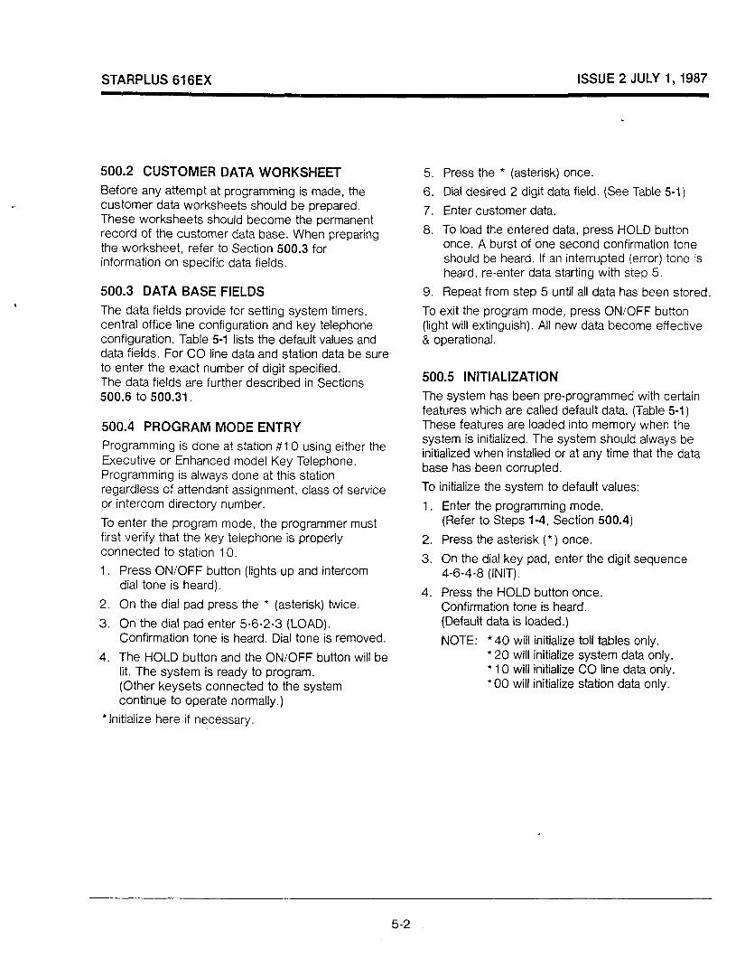
500.2 CUSTOMER DATA WORKSHEET
Before any attempt at programming is made, the customer data worksheets should be prepared. These worksheets should become the permanent record of the customer data base. When preparing the worksheet, refer to Section 500.3 for information on specific data fields.
500.3 DATA BASE FIELDS
The data fields provide for setting system timers, central office line configuration and key telephone configuration. Table 5-1 lists the default values and data fields. For CO line data and station data be sure to enter the exact number of digit specified. The data fields are further described in Sections 500.6 to 500.31.
500.4 PROGRAM MODE ENTRY Programming is done at station #l 0 using either the Executive or Enhanced model Key Telephone. Programming is always done at this station regardless of attendant assignment, class of service or intercom directory number.
To enter the program mode, the programmer must first verify that the key telephone is properly connected to station 10.
1.
2.
3.
4.
Press ON/OFF button (lights up and intercom dial tone is heard).
On the dial pad press the l (asterisk) twice.
On the dial pad enter 5-6-2-3 (LOAD). Confirmation tone is heard. Dial tone is removed.
The HOLD button and the ON/OFF button will be lit. The system is ready to program. (Other keysets connected to the system continue to operate normally.)
5.
6.
7.
a.
9.
Press the * (asterisk) once.
Dial desired 2 digit data field. (See Table 5-1)
Enter customer data.
To load the entered data, press HOLD button once. A burst of one second confirmation tone should be heard. If an interrupted (error) tone is heard, re-enter data starting with step 5.
Repeat from step 5 until all data has been stored.
To exit the program mode, press ON/OFF button (light will extinguish). All new data become effective & operational.
500.5 lNlTlALlZATlON
The system has been pre-programmed with certain features which are called default data. (Table 5-f) These features are loaded into memory when the system is initialized. The system should always be initialized when installed or at any time that the data base has been corrupted.
To initialize the system to default values:
1.
2.
3.
4.
Enter the programming mode. (Refer to Steps l-4, Section 500.4)
Press the asterisk (* ) once.
On the dial key pad, enter the digit sequence 4-6-4-8 (INIT).
Press the HOLD button once. Confirmation tone is heard. (Default data is loaded.)
NOTE: *40 will initialize toll tables only. * 20 will initialize system data only. * 10 will initialize CO line data only. *00 will initialize station data only.
* Initialize here if necessary.
5-2

STARPLUS 616EX ISSUE 2 JULY 1,1987
Field Description Data Field Sub Field
Station Configuration Class of Service DND SYStem Speed Dial Access Alarm/Door Signal Preferred Line Answer Call Forwarding Direct DSS CO Select Headset Paging Access Flexible DSS CO line access Page Group Pickup Group
CO Line Configuration tine Group Lind Type Signalling Toll Override Private Line
CO Line Ring-Day CO Line Ringing-Night Flash Timer CO Ring Detect Dial Pulse System Configuration
CO’Line Queuing Hold Preierence Alarm Detection Alarm Signalling Automatic Privacy Alarm Enable BGM Enable
Exclusive Hold Recall System Hold Recall Transfer Recall Timer Message Reminder Tone Pause Timer Executive/Secretary Loud Bell Control PBX Codes Attendant Position Ring Timer-Preset Station Assign. - Preset Conference Timer SMDR SMDRlBaud Rate Toll Table Allow A Toll Table Deny A Toll Table Allow B Toll Table Deny B
01 02 02 02 02 02 02 03 03 04 05 06 07
11 12 12 12 12 13 14 15 16 17
21 21 21 21 21 21 21 22 23 24 25 26 27 28 30 31 32 33 34 35 36 41 42 43 44
TABLE 5-l DATA FIELDS AND DEFAULT VALUES
I Default Entry
All stations set at COS Enabled for all stations Enabled for all stations Disabled at all stations Disabled at all stations Allowed at all stations Allowed at all stations Disabled Allowed at all stations Sequential, Sta 10 on DSS button 1 All stations access all lines All stations in group 1 All stations in group 1
All CO lines in group 1 All lines assigned as CO lines All CO lines set at DTMF Disabled for all CO lines None assigned All ring at attendant station (10) All ring at attendant station (10) 2 seconds 300 msec. 60/40, 10 pps
Allowed at all stations Primary hold is system Closed loop Continuous Enabled at all stations Disabled Disabled 60 seconds 60 seconds 30 seconds Disabled (00) 2 seconds None assigned None assigned None assigned STA 10 as attendant 15 seconds None assigned 15 minutes Enabled for all lines All call/300 baud None assigned None assigned None assigned None assigned -
5-3

STARPLUS 616EX ISSUE 2 JULY 1,198
500.6 STATION CLASS OF SERVICE (Data Field 01)
Press DSS button of station to be assigned COS.
Press CO line button of class desired (LED is lit): Class 1 =CO line 1 button Class 2=CO line 2 button Class 3=CO line 3 button Class 4=CO line 4 button Class 5=CO line 5 button Class 6=CO line 6 button
Press HOLD button.
500.7 STATION DATA (Data Field 02)
Press STA button for station to be programmed.
Toggle CO line buttons on and off to determine features. If the associated LED is lit, the feature is allowed.
CO 1 =do not disturb CO 2=system speed access CO 3=alarm/door signal CO 4=preferred line answer CO 5=call forward CO 6=auto select
After programming a station, press HOLD button.
The LED for the next station will light for programming.
Toll restriction is assignable on a per station basis. There are 6 possible classes of service:
Class 1 - unrestricted Class 2 - follows entries in Allow & Deny Table A Class 3 -follows entries in Allow & Deny Table B Class 4 - allows 7 digits (8 or 9 if PBX line),
denies 0 & 1 as first dialed digit Class 5 - DSS calls & paging only Class 6 - receive only:phone box
By default all are assigned COS 1 .
When a CO line is marked PBX, COS restrictions apply to the station only if one of 4 codes are dialed first.
Do Not Disturb A yes entry (LED on) indicates this station is allowed the DND feature.
System Speed A yes entry (LED on) indicates this station is allowed access to system speed dial numbers. The last 20 numbers are not montiored and will override toll restriction.
Alarm/Door Signal The system can transmit an alarm signal to all available (non-busy) keysets programmed to receive this signal. A yes entry (LED on) means the station will receive the signal. Also assigns which stations receive alert tone from a phone box.
Perferred Line Answer Allows a station to answer any phones assigned to ring at that station by simply lifting the handset. A yes entry (LED on) allows the station this feature.
Call Forwarding A station allowed this feature (LED on) can have intercom, transferred CO lines and incoming ringing CO lines forwarded to another station.
5-4

STARPLUS 616EX ISSUE 2 JULY 1,1987
Auto Select A station allowed this feature (LED on) can automatically place the telephone in the dialing mode by simply pressing a DSS or CO line button. When the called party answers, the handset must be lifted to converse unless equipped with a speakerphone.
I STATION DATA (Data Field 03)
Press STA button for station to be programmed. ;, Headset
TO change a feature, press appropriate CO line A yes entry (LED on) means that the station has
button so LED lights up or extinguishes. been equipped with a headset. Refer to
CO 1 - headset Section 4.16.
CO 2 - page access Page Access Press HOLD button. A yes entry (LED on) means this station is allowed
to make pages. A no entry restricts the station from initiating any type of page.
500.8 STA ASSIGNMENTS (Data Field 04)
Press STA button of station to be moved.
Press STA button of location it’s being moved to. (A beep tone will be heard.)
Make all entries for all stations being moved. Then press HOLD button.
If error tone is heard, duplicate or unassigned numbers have been entered. Re-enter the data field and try again.
To check which assignments have been made, press a DSS button. If that station has been moved, the button pressed will be lit steady and the location it was moved to will flash. If no changes are to be made, just press HOLD again. If upon pressing the button, it remains flashing, the physical and logical locations remain the same.
By default STA 10 button corresponds with station 10, STA 11 button with station 11, etc.
This can be changed if desired. When STA appearances are changed, all station data follows the station. The original location of station IO always remains the programming location regardless of STA number assigned to it.
This feature allows one person to move from one station to another without changing phone and yet take all individual station data including intercom number with them.
Each station must be assigned a unique circuit number (physical location). For example if 1 1 is moved to 12 then 12 must be moved somewhere. 12 could be moved to 14 and then 14 moved to 11. The system does not allow duplicate or unassigned numbers.
If station data is to be changed for a station that has been moved, the data will be programmed wherever the station has been moved to, not at the original physical location.
5-5
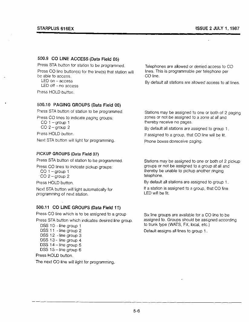
STARPLUS 616EX ISSUE 2 JULY 1,1987
500.9 CO LINE ACCESS (Data Field 05)
Press STA button for station to be programmed.
Press CO line button(s) for the line(s) that station will be able to access.
LED on -access LED off - no access
Press HOLD button.
500.10 PAGING GROUPS (Data Field 06)
Press STA button of station to be programmed
Press CO lines to indicate paging groups: CO 1 -group 1 CO 2 -group 2
Press HOLD button.
Next STA button will light for programming.
PICKUP GROUPS (Data Field 07)
Press STA button of station to be programmed.
Press CO lines to indicate pickup groups: CO 1 -group 1
-CO 2-group 2
Press HOLD button.
Next STA button will light automatically for programming of next station.
500.11 CO LINE GROUPS (Data Field 11)
Press CO line which is to be assigned to a group
Press STA button which indicates desired line group. DSS 10 - line group 1 DSS 11 -line group 2 DSS 12 - line group 3 DSS 13 - line group 4 DSS 14 - line group 5 DSS 1.5 - line group 6
Press HOLD button.
The next CO line will light for programming.
Telephones are allowed or denied access to CO lines. This is programmable per telephone per CO line.
By default all stations are allowed access to all lines.
Stations may be assigned to one or both of 2 paging zones or not be assigned to a zone at all and thereby receive no pages.
By default all stations are assigned to group 1
If assigned to a group, that CO line will be lit.
Phone boxes do receive paging.
Stations may be assigned to one or both of 2 pickup groups or not be assigned to a group at all and thereby be unable to pickup another ringing telephone.
By default all stations are assigned to group 1 .
If a station is assigned to a group, that CO line LED will be lit.
Six line groups are available for a CO line to be assigned to. Groups should be assigned according to trunk type (WATS, FX, local, etc.)
Default assigns all lines to group 1
5-6
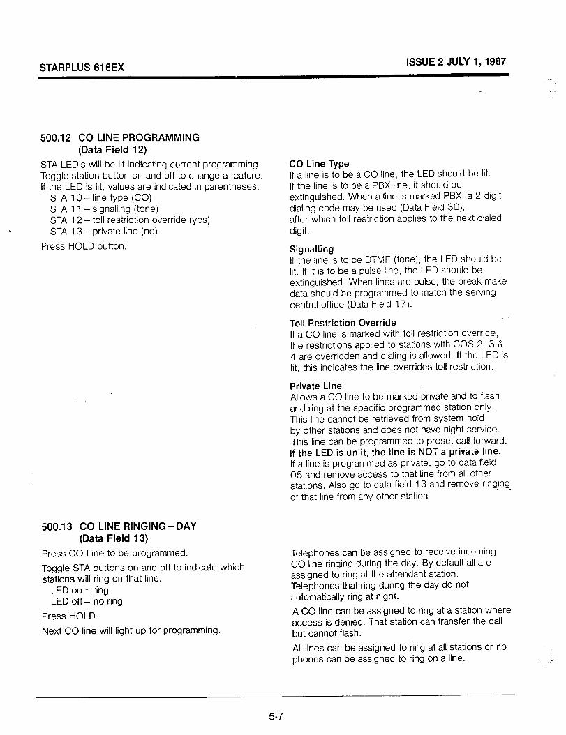
STARPLUS 616EX ISSUE 2 JULY 1,1987
500.12 CO LINE PROGRAMMING (Data Field 12)
STA LED’s will be lit indicating current programming. Toggle station button on and off to change a feature. If the LED is lit, values are indicated in parentheses.
STA 10 - line type (CO) STA 1 1 - signalling (tone) STA 12 - toil restriction override (yes) STA 13 - private line (no)
Press HOLD button.
500.13 CO LINE RINGING -DAY (Data Field 13)
Press CO Line to be programmed.
Toggle STA buttons on and off to indicate which stations will ring on that line.
LED on = ring LED off = no ring
Press HOLD.
Next CO line will light up for programming.
CO Line Type If a line is to be a CO line, the LED should be lit. If the line is to be a PBX line, it should be extinguished. When a line is marked PBX, a 2 digit dialing code may be used (Data Field 30), after which toll restriction applies to the next dialed digit.
Signalling If the line is to be DTMF (tone), the LED should be lit. If it is to be a pulse line, the LED should be extinguished. When lines are pulse, the break, make data should be programmed to match the serving central office (Data Field 17).
Toll Restriction Override If a CO line is marked with toll restriction override, the restrictions applied to stations with COS 2, 3 & 4 are overridden and dialing is allowed. If the LED is lit, this indicates the line overrides toll restriction.
Private Line Allows a CO line to be marked private and to flash and ring at the specific programmed station only. This line cannot be retrieved from system hold by other stations and does not have night service. This line can be programmed to preset call forward. If the LED is unlit, the line is NOT a private line. If a line is programmed as private, go to data field 05 and remove access to that line from all other stations. Also go to data field 13 and remove ringing of that line from any other station.
Telephones can be assigned to receive incoming CO line ringing during the day. By default all are assigned to ring at the attendant station. Telephones that ring during the day do not automatically ring at night.
A CO line can be assigned to ring at a station where access is denied. That station can transfer the call but cannot flash.
All lines can be assigned to ring at all stations or no phones can be assigned to ring on a line.
5-7
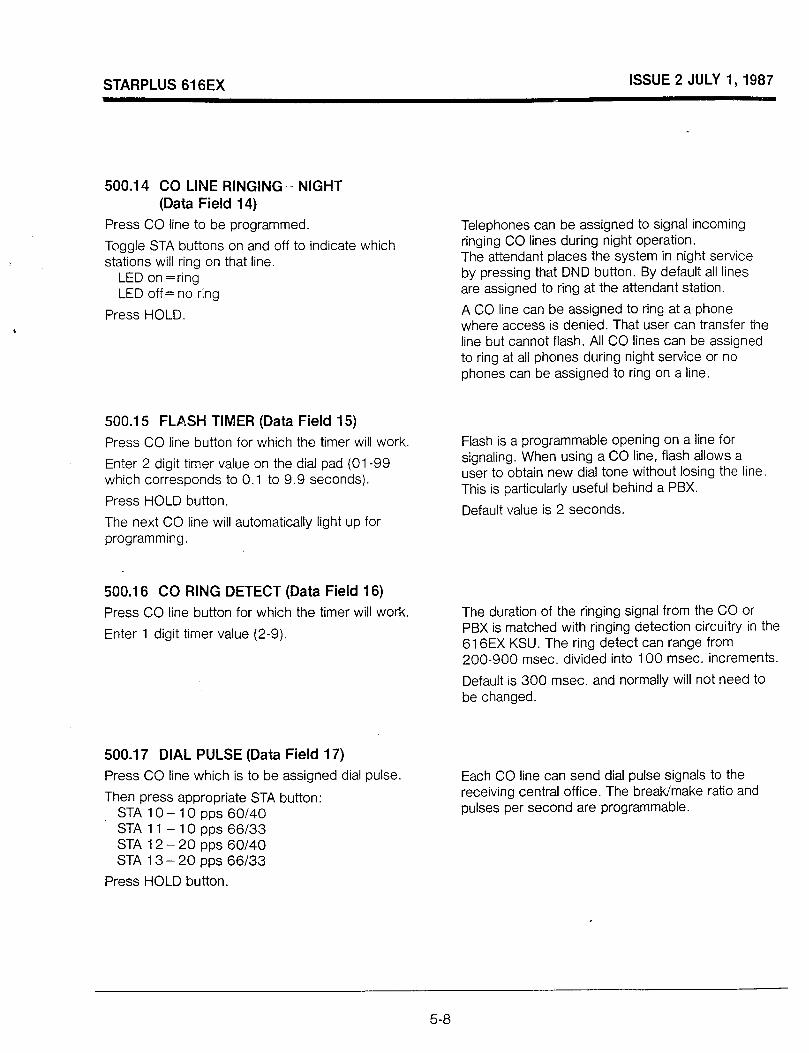
STARPLUS 616EX ISSUE 2 JULY 1,1987
500.14 CO LINE RINGING - NIGHT (Data Field 14)
Press CO line to be programmed.
Toggle STA buttons on and off to indicate which stations will ring on that line.
LED on =ring LED off= no ring
Press HOLD.
500.15 FLASH TIMER (Data Field 15)
Press CO line button for which the timer will work.
Enter 2 digit timer value on the dial pad (01-99 which corresponds to 0.1 to 9.9 seconds).
Press HOLD button.
The next CO line will automatically light up for programming.
500.16 CO RING DETECT (Data Field 16)
Press CO line button for which the timer will work.
Enter 1 digit timer value (2-9).
500.17 DIAL PULSE (Data Field 17)
Press CO line which is to be assigned dial pulse.
Then press appropriate STA button: STAlO-lOpps60/40 STA 11 - 10 pps 66/33 STA 12 - 20 pps 60140 STA 13 - 20 pps 66/33
Press HOLD button.
Telephones can be assigned to signal incoming ringing CO lines during night operation. The attendant places the system in night service by pressing that DND button. By default all lines are assigned to ring at the attendant station.
A CO line can be assigned to ring at a phone where access is denied. That user can transfer the line but cannot flash. All CO lines can be assigned to ring at all phones during night service or no phones can be assigned to ring on a line.
Flash is a programmable opening on a line for signaling. When using a CO line, flash allows a user to obtain new dial tone without losing the line. This is particularly useful behind a PBX.
Default value is 2 seconds
The duration of the ringing signal from the CO or PBX is matched with ringing detection circuitry in the 616EX KSU. The ring detect can range from 200-900 msec. divided into 100 msec. increments.
Default is 300 msec. and normally will not need to be changed.
Each CO line can send dial pulse signals to the receiving central office. The break/make ratio and pulses per second are programmable.
5-8
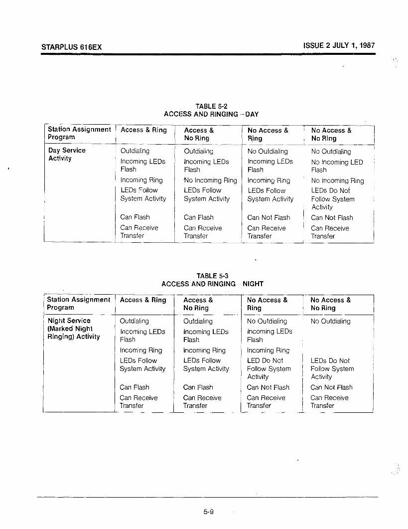
STARPLUS 616EX ISSUE 2 JULY 1,1987
Station Assignment Program
Day Service Activity
Station Assignment Program
Night Service (Marked Night Ringing) Activity
TABLE 5-2 ACCESS AND RINGING -DAY
Access & Ring
~___~ Outdialing
Incoming LEDs Flash
Incoming Ring
LEDs Follow System Activity
Can Flash
Can Receive Transfer
Access & No Ring
Outdialing
Incoming LEDs Flash
No Incoming Ring
LEDs Follow System Activity
Can Flash
Can Receive Transfer
i-
No Access & No Access & R,ing , No Ring
~, / No Outdialing ’ No Outdialing
I
Incoming LEDs /
Flash No Incoming LED j Flash
Incoming Ring No Incoming Ring
LEDs Follow System Activity
Can Not Flash
Can Receive Transfer
.
TABLE 5-3 ACCESS AND RINGING - NIGHT
Access & Ring
Outdialing
Incoming LEDs Flash
Incoming Ring
LEDs Follow System Activity
Can Flash
Can Receive Transfer
Access & No Ring
Outdialing
Incoming LEDs Flash
Incoming Ring
LEDs Follow System Activity
Can Flash
Can Receive Transfer
i
LEDs Do Noi I Follow System i Activity /
Can Not Flash !
Can Receive / Transfer / I
No Access & No Access & Ring No Ring
No Outdialing i No Outdialing
Incoming LEDs Flash
Incoming Ring ;
LED Do Not I LEDs Do Not Follow System ( Follow System Activity / Activity
Can Not Flash 1 I Can Not Flash
Can Receive i Can Receive Transfer Transfer
5-9

STARPLUS 616EX ISSUE 2 JULY 1, 1987
500.18 SYSTEM CONFIGURATION (Data Field 21)
STA LED’s will be lit indicating current programming. STA 10 -queuing STA 1 1 - hold preference STA 12 - alarm detection STA 13 - alarm signaling mode STA 14 - automatic privacy STA 15 -alarm enable STA 16 - BGM enable
Toggle STA buttons on and off to change features STA 10 lit - queuing allowed STA 1 1 lit - system hold STA 12 lit - closed loop STA 13 lit - continuous tone STA 14 lit - privacy enabled STA 15 lit - alarm enabled STA 16 lit - BGM enabled
Press HOLD button.
Queuing If this button is lit, queuing is allowed on a system basis. Stations queuing a line are recalled according to line group queued.
Hold Preference The system may be programmed to have either exclusive hold or system hold preferred. If exclusive hold is preferred, depress HOLD button once for exclusive hold and twice for system hold. If system hold is preferred, depress HOLD button once for system hold and twice for exclusive hold. Transfer and conference calls are always placed on exclusive hold.
Alarm Detection Determines type of alarm signal received. LED lit means closed loop; unlit means open loop.
Alarm Signaling Determines type of signaling received. LED lit means continuous tone; unlit means single tone. Single tone is used for phone box signaling.
Automatic Privacy A yes entry (LED lit) means that privacy is automatically provided on all communications in the system. To eliminate privacy, extinguish the LED.
Alarm Enable A yes entry (LED lit) means the system is programmed for alarm. Stations must then be programmed to receive the alarm signal (Data Field 02). This also determines which stations receive alert tone from phone boxes. You must also choose alarm signaling - STA button 12 and 13.
Background Music If a music source has been installed and background music is desired, toggle this button ON so the LED is lit. If this button is unlit, no background music will be received through telephone speakers.
5-10

STARPLUS 616EX ISSUE 2 JULY I,1987
500.19 SYSTEM TIMERS (Data Fields 22-26)
Exclusive Hold Recall (Data Field 22)
Enter data field and dial 3 digit number between 000 and 255.
Press HOLD button.
System Hold Recall (Data Field 23)
Enter data field and dial 3 digit number between 000 and 255.
Press HOLD button.
Transfer Recall (Data Field 24)
Enter data field and dial 3 digit number between 000 and 25.5.
Press HOLD button.
Message Wait Reminder Tone (Data Field 25)
Enter data field and dial 2 digit number between 00 and 99.
Press HOLD button.
Pause Timer (Data Field 26)
Enter data field and dial 1 digit number between 1 and 9.
Press HOLD button.
Reflects elapsed time before a call placed on exclusive hold will recall the initiating station. If unanswered for the same elapsed time, will recall the attendant and if unanswered by the attendant will recall all phones in the system. Default is 060 seconds.
Reflects time elapsed before an unanswered system hold is recalled to the station that initiated it. If unanswered for the same elapsed time will recall the attendant and if unanswered by the attendant will recall all phones in the system. Default is 060 seconds.
Reflects the time elapsed before an unanswered transfer is recalled to the station that initiated it. If unanswered for the same elapsed time will recall the attendant and if unanswered by the attendant will recall all phones in the system. Default is 030 seconds.
A station with a message waiting can be reminded at a timed interval with a tone. The tone will periodically repeat until all messages have been answered. The interval can be programmed between 00 and 99 minutes. By default the timer is diabled.
When dialing a speed number, a timed pause in digit sending can be inserted into the number. The length of the pause is controlled by the pause timer and can be from 1 to 9 seconds. Default is 2 seconds.
.,’
5-I 1
STARPLUS 616EX ISSUE 2 JULY 1, 1987
500.20 EXECUTIVE/SECRETARY ASSIGNMENTS (Data Field 27)
Upon entering program field, CO line 1 will be lit for entering the first pair.
Press STA button to assign executive. (LED will light steady)
Press second STA button to assign secretary. (LED will flash)
Press HOLD button.
CO line 2 will light for programming the second pair, then CO line 3 for the third pair and CO line 4 for the forth pair. Press HOLD after each pair entered.
There are 4 sets of Executive/Secretary pairs available for assignment. When the Executive is busy or in DND, intercom calls and transfers will be automatically routed to the secretary(ies).
One executive can go to 4 secretaries, 1 secretary can answer for 4 executives, or 1 executive can be assigned 1 secretary.
To cancel an assignment, press CO line button of that assignment and then press any STA button twice. Press HOLD button.
500.21 LOUD BELL CONTROL (Data Field 28)
Enter data field and press station button of station to be assigned ringing. (LED will light)
Press HOLD button.
500.22 PBX DIALING CODES (Data Field 30)
Upon entering data field, CO line 1 will light for programming the first code number.
Enter the 2 digit number on the dial pad. If the number is only 1 digit, enter the pound (#) as the second digit.
Press HOLD button.
Next CO lines will light for programming the other 3 codes.
One loud bell control is available and can be assigned to any station. Loud Bell contacts will follow the assigned CO line and intercom ringing of that station. None are assigned by default.
Four 2 digit PBX access codes can be entered into system memory. When dialed, they signal the system that an access code is being dialed and that toll restriction is to be applied at the next dialed digit. Otherwise toll restriction does not apply. This allows dialing of PBX extensions 100, 1 10, 111, etc.
A one digit code may be used.
500.23 ATTENDANT POSITION (Data Field 31)
Enter data field and press STA station button of the station that is to be the attendant.
Press HOLD button.
One station must be assigned as the attendant for line recalls and entering the system into night service by pressing the DND button. Attendant position does not have DND. System speed numbers are entered at the attendant station.
5-12

STARPLUS 616EX ISSUE 2 JULY 1,1987
500.24 CALL FORWARD PRESET (Data Fields 32 and 33)
Station Assignment (Data Field 33)
Press STA button of station to be automatically Ringing CO lines can be forwarded to another forwarded (LED lights steady). predetermined station if the original station is busy or
Press STA button of station to receive the forwarded does not answer. These lines will ring for a
call (LED flashes). programmed period of time before forwarding.
Make all entries desired. During this time the busy station will hear muted
, ringing. Press HOLD button.
To remove a station from preset forward, press that STA button twice.
Ring Timer for Preset Forward (Data Field 32) Enter data field and dial 2 digit number between 10 and 99 (seconds).
Press HOLD button.
500.25 CONFERENCE TIMER (Data Field 34)
Enter data field and dial 2 digit number between 00 and 99.
Press HOLD button.
Determines the amount of time a call will ring into a station before automatically forwarding to the predetermined station. Default sets the timer at 15 seconds.
Reflects amount of time a conference circuit will remain active if initiator of the conference is no longer actively in the conference. A warning tone will be presented to remaining users 15 seconds prior to shutdown. The initiator cannot make other calls while the conference continues. Default is 15 minutes.
500.26 SMDR (Data Field 35)
Upon entering the data field, all CO lines will be lit and STA 10 button will be lit.
To disable a particular line from recording calls, press that CO line button so the light extinguishes.
Press HOLD button.
Station Message Detail Recording is an optional feature that allows customers to keep track of either all calls or only long distance calls both incoming and outgoing by CO line, number dialed, time of day, date, station that placed the call, duration of call and account code if used.
Requires the Enhanced KSU and Program Module II.
5-13
STARPLUS 616EX ISSUE 2 JULY I,1987
500.27 SMDRlBAUD RATE (Data Field 36)
Station buttons 10 and 1 1 govern these features: 10 - all calls (lit) or long distance only (unlit) 1 1 - 300 baud (lit) or 1200 baud (unlit)
Toggle buttons on or off according to programming desired.
Press HOLD button.
500.28 DATA BASE PRINTOUT (Data Field 37) Press I‘ l 37” on the dial pad. Then press one of the following buttons depending on what information is needed in the printout.
STA 10 - station data STA 1 1 - CO line data STA 12 - system data STA 13 - timers STA 14 - toll tables STA 15 - system speed numbers STA 16 - complete data base STA 17 - abort the program
SMDR can be programmed to record ail calls both incoming and outgoing or it can be programmed to record only outgoing long distance.
The baud rate can be set at 300 or 1200 baud. The mini-printer operates at 1200 baud.
By default all calls are recorded and the baud rate is set at 300.
Requires the Enhansed KSU, Program Module II and a printer to obtain a printout of the data base.
5-14

STARPLUS 616EX ISSUE 2 JULY I,1987
TABLE 5-5 SAMPLE DATA BASE PRINTOUT
STATION CONFIG
CKT NUM COS DND SPD ALM PFL 10 1 1 Y Y N N
CF DSLT CO ACCESS B/NA Y Y 123456
PGGRP PKGRP PGACC HDST < 1 1 Y N
Cl<T =Station port number NUM =Intercom number cos =Class of service DND =Do not disturb SPD =System speed dial access .ALM =Alarm tone PFL = Per-ferred line answer CF =Call forward DSLT = Direct select CO ACCESS=CO lines accessed BiNA =Preset call forward PGGRP = Page group PKGRP =Pickup group PGACC = Page access HDST = Headset operation
CO CONFIG
CO GRP TYPE SIGL TRO PVL FLSH 1 1 co DTMF N N 20
RDT DIAL-PLS PBX CODES SMDR 3 60/40;10 -- -- -- -- Y
DAY RING: 10 __ __ __ __ __ _- --
NIGHT RING: 10 __ __ -_ -- -- -- -- __ __ -- -- -- -- -- --
CO =CO line number GRP =Group line assigned to TYPE=CO or PBX SIGL =DTMF or DP TRO =Toll restrict override PVL =Private line FLSH = Flash time RTD =Ring detect timer
SYS CONFIG
QUE HOLD ALM:DT SIGL ENBL Y SY CL REPT N
PRV BGM Al-TD LBC:l Y N 01
SMDR BAUD ALL 300
EX/SCl EXISC2 EXSC3 EX’SC4
QUE =Line queue HOLD =System or exclusive ALM = Alarm parameters DT =Closed or open SIGL =Once or repeated ENBL = Enabled PRV =Automatic privacy All-D =Assigned attendant LBC: 1 =Loud bell control SMDR =All call or long distance BAUD =300 or 1200 EXISC = Exec./secretary pair
TIMERS
ERCL SRCL TRCL MSG-TNE PAUSE 060 060 030 000 2
RING-FWD CNFTO 15 15
ERCL = Exclusive recall time SRCL =System recall time TRCL =Transfer recall time MSG-TNE =Message wait
Reminder tone RING-FWD=Preset forward time CNFTO =Conference time-out
5-15
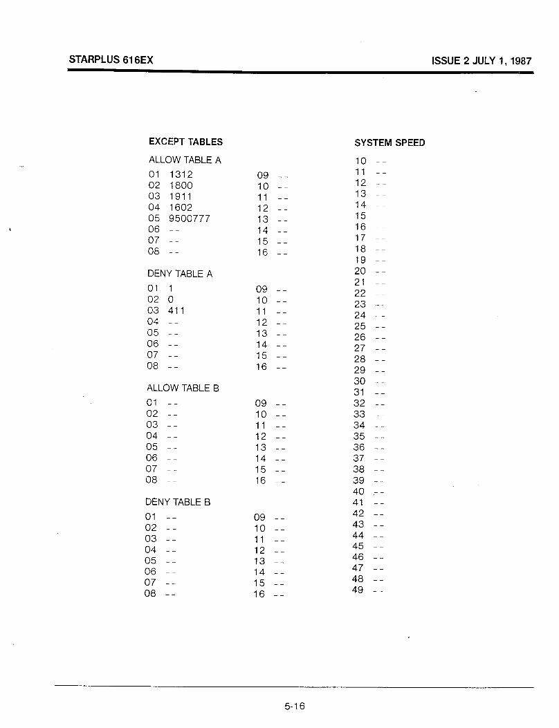
iTl
D
in
cn

STARPLUS 616EX ISSUE 2 JULY 1, 1987
500.29 TOLL RESTRICTION TABLES (Data Field 41 -44)
Use the following Data Fields to program toll tables:
Toll Allow Table A - Field 41 Toll Allow Table B - Field 42 Toll Allow Table B - Field 43 Toll Deny Table B - Field 44
- Upon entering the data field, DSS button #l 0 will be lit.
- Dial the allow/deny number including ‘don’t cares’. (8 digits maximum)
- Press HOLD for entering the data. DSS button #I 1 will then automatically light up.
- Enter the next allow/deny number.
-When all of the numbers needed have been programmed and entered, either enter another data field or leave the program mode.
The Allow/Deny tables are organized into two sets of tables to allow the 616EX system to support 2 different toll plans at one installed site. Allow/Deny Table A is referenced whenever a station is assigned Class of Service 2; and Allow/Deny Table B is reference whenever a station is assigned Class of Service 3. Each table may contain up to 16 numbers of up to 8 digits each. Any number of digits up to 8 maximum may be entered. Less than 8 digits may be entered. For example, the programmer needs only to dial “0” and press HOLD to program operator restriction.
The following rules should be remembered when setting up the Allow/Deny tables: (Figure 5.1)
1.
2.
3.
4.
5.
If nothing is assigned in either the allow or deny table, no restriction is applied.
If entries are made in the allow table and only there, then only the numbers in the table are allowed. (Allow Only Restriction)
If entries are made in the deny table and only there, then only the numbers in the table are denied. (Deny Only)
If there are entries in both tables, the allow table is searched first, and if the dialed number is found, it is allowed. If it is not found in the allow, the deny table is searched. If the number is -found in the deny, it is denied; if it is not found there, it is allowed.
Exchange Codes can be blocked by specific entries in the Deny lists or allowed by specific entries in the Allow lists.
When the pound (X) is used, it enters a don’t care charater. This will allow or deny any digit O-9 in that location.
The Allow & Deny tables are reserved for COS 2 and 3 respectively. See Data Field 01
When a CO Line is marked PBX, COS restrictions apply to the station only if one of 4 PBX codes are dialed first.
A CO line marked Toll Restriction Override is not subject to restriction of COS 2, 3 or 4.
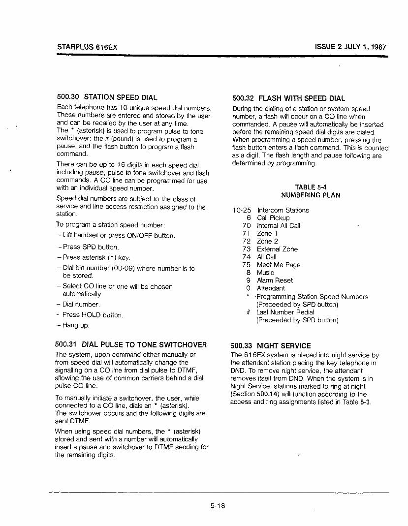
STARPLUS 616EX ISSUE 2 JULY 1,1987
500.30 STATION SPEED DIAL
Each telephone has 10 unique speed dial numbers. These numbers are entered and stored by the user and can be recalled by the user at any time. The * (asterisk) is used to program pulse to tone switchover; the # (pound) is used to program a pause; and the flash button to program a flash command.
There can be up to 16 digits in each speed dial including pause, pulse to tone switchover and flash commands. A CO line can be programmed for use with an individual speed number.
Speed dial numbers are subject to the class of service and line access restriction assigned to the station.
To program a station speed number:
- Lift handset or press ON/OFF button.
- Press SPD button.
- Press asterisk (*) key.
- Dial bin number (00-09) where number is to be stored.
- Select CO line or one will be chosen automatically.
- Dial number.
- Press HOLD button.
- Hang up.
500.31 DIAL PULSE TO TONE SWITCHOVER The system, upon command either manually or from speed dial will automatically change the signalling on a CO line from dial pulse to DTMF, allowing the use of common carriers behind a dial pulse CO line.
To manually initiate a switchover, the user, while connected to a CO line, dials an l (asterisk). The switchover occurs and the following digits are sent DTMF.
When using speed dial numbers, the * (asterisk) stored and sent with a number will automatically insert a pause and switchover to DTMF sending for the remaining digits.
500.32 FLASH WITH SPEED DIAL
During the dialing of a station or system speed number, a flash will occur on a CO line when commanded. A pause will automatically be inserted before the remaining speed dial digits are dialed. When programming a speed number, pressing the flash button enters a flash command. This is counted as a digit. The flash length and pause following are determined by programming.
TABLE 5-4 NUMBERING PLAN
1 O-25 Intercom Stations 6 Call Pickup
70 Internal All Call 71 Zone 1 72 Zone 2 73 External Zone 74 All Call 75 Meet Me Page
8 Music 9 Alarm Reset 0 Attendant * Programming Station Speed Numbers
(Preceeded by SPD button) # Last Number Redial
(Preceeded by SPD button)
500.33 NIGHT SERVICE The 616EX system is placed into night service by the attendant station placing the key telephone in DND. To remove night service, the attendant removes itself from DND. When the system is in Night Service, stations marked to ring at night (Section 500.14) will function according to the access and ring assignments listed in Table 5-3.
5-l 8
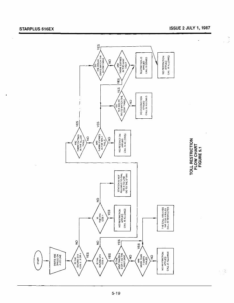
DIG
ITS
A
RE
D
IALE
D
ON
\ A
CO
LIN
E
NO
RE
STR
ICTI
ON
A
PP
LIE
D
CA
LL
6 A
LLO
WE
D
YE
S
NO
R
ES
TRIC
TIO
N
CA
LL
IS A
LLO
WE
D
THE
C
ALL
V
IOLA
TES
TH
E C
OS
4
RU
LES
C
ALL
IS
RE
STR
ICTE
D
TOLL
R
ES
TRIC
TIO
N
FLO
W
CH
AR
T FI
GU
RE
5.
1
I
DO
TH
E
DIA
LED
Y
ES
Y
ES
A
RE
DIG
ITS
M
ATC
H
THE
TH
ER
E
EN
TRIE
S
3
DE
NY
TA
BLE
IN
TH
E
DE
NY
TA
BLE
NO
NO
R
ES
TRIC
TIO
N
RE
STR
JCT~
~N
is
AP
PLI
ED
C
ALL
IS
ALL
OW
ED
C
ALL
IS
DE
NIE
D
NO
RE
STR
ICTI
ON
CA
LL
IS A
LLO
WE
D
,

STARPLUS 616EX ISSUE 2 JULY I,1987
CO LINE PROGRAMMING
Private Line 12 DSS 13 None
Day Ring 13 All Ring Attendant
Night Ring 14
Flash Timer 15
Ring Detect 16
Dial Pulse 17
All Ring Attendant
2 sec.
300 msec.
60/40 10 PPS
5-20

STARPLUS 616EX ISSUE 2 JULY I,1987
‘\
SYSTEM PROGRAMMING
27 Executive/Secretary 4 Pairs Sta #, Sta ff
None
28 Loud Bell Control Sta # None
30 PBX Codes 4 Nos., 1 or 2 Digit
None
31 Attendant Position 1 o-25 Sta 10
32 Ring Timer - Preset Fwd 1 O-99 sec. 15 sec.
33 Station - Preset Fwd Unlimited Sta#, Sta#
None
34 Conference Timer 00-99 min 15 min L
5-21

STARPLUS 616EX ISSUE 2 JULY 1,1987
STATION PROGRAMMING
‘
Class of Service
Do Not Disturb
System Speed
Preferred Line Ans.
Call Fwd
Auto Select
Headset
Page Access
CO Line Access
‘Page Grp
Pickup Grp
STATION
PROGRAMCODE 10 11 12 13 14 15 16 17 DEFAULT
01 cos 1
02 co 1 Yes
02 co 2 Yes
02CO4 No
02 co 5 Yes
02CO6 Yes
03COl No
03CO2 Yes
05 All Sta., All Lines
06 Group 1
07 Group 1
(04) DSS ASSIGNMENTS (Station no. to Station no.)
FROM TO FROM TO FROM TO FROM TO FROM TO FROM TO
FROM TO FROM TO FROM TO FROM TO FROM TO FROM TO
,
5-22

STARPLUS 616EX ISSUE 2 JULY I, 1987
Programmed at Attendant Station. SYSTEM SPEED DIAL DIGITS
1 2 3 4 5 6 7 8 9 IO 11 12 13 14 15 16 10
/ I I I
B22; i ! ! 1,231 j ;
N24/ 1 1 L25j : /
; _+--__I
_ -_/_j_ ,
0, 26 i i I
/ ;I 27 / i I I I
/ I I I / I / i
T28 I / , I I I
I 29 I I I
030 / I I
;31 I- I j --7 32 I
_ ___.~I 33 ! / j I
-1 34 I ’ 35
I / ! I I : I / / I -.
36
37 I i,j ;I;;]
I 38
39 I -.i_ 40 I / i 41
42 I- I
43 44 /
45 1 46
47
48 49
5-23

STARPLUS 616EX ISSUE 2 JULY 1,1987
Code 41 -Allow Table A
11
Bin 12 1
’ I Bin 13 I Bin 14 /
I , I I I I I I I
Bin 15 ! I I I I I I 1 Bin 16 / I I I I I I I I I I I I I I I I I 1
Code 42 -Deny Table A Digits
I I I I I i I
Code 43-Allow Table B Digits
5-24
Code 44-Deny Table B
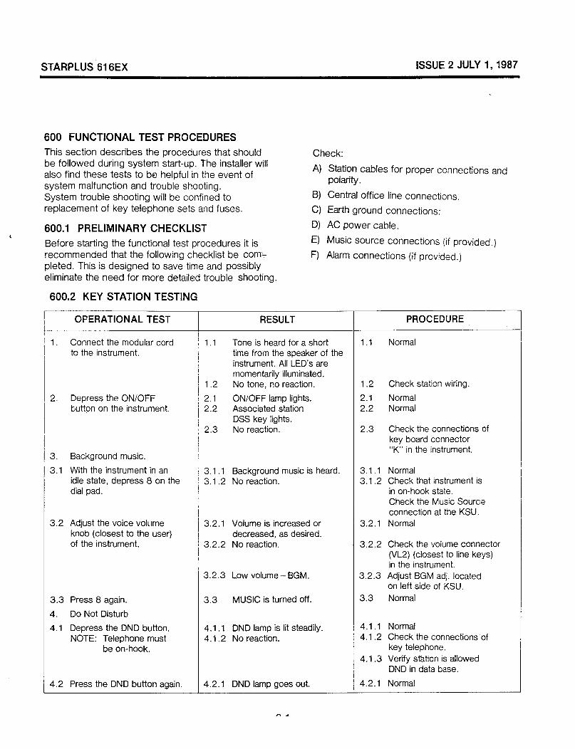
STARPLUS Si SEX ISSUE 2 JULY 1,1987
SO0 FUNCTIONAL TEST PROCEDURES
This section describes the procedures that should be followed during system start-up. The installer will also find these tests to be helpful in the event of system malfunction and trouble shooting. System trouble shooting will be confined to replacement of key telephone sets and fuses.
600.1 PRELIMINARY CHECKLIST ,
Before starting the functional test procedures it is recommended that the following checklist be com- pleted. This is designed to save time and possibly eliminate the need for more detailed trouble shooting.
600.2 KEY STATION TESTING
Check:
A) Station cables for proper connections and polarity.
B) Central office line connections.
C) Earth ground connections:
D) AC power cable.
E) Music source connections (if provided.)
F) Alarm connections (if provided.)
r c OFERATIONAL TEST RESULT PROCEDURE
1. Connect the modular cord 1 1.1 Tone is heard for a short 1 .l Normal to the instrument. I time from the speaker of the
, instrument. All LED’s are I
i 1.2 momentarily illuminated. No tone, no reaction. 1.2 Check station wiring.
2. Depress the ON/OFF ; 2.1 ON/OFF lamp lights. 2.1 Normal button on the instrument. / 2.2 Associated station 2.2 Normal
DSS key iights. I 2.3 No reaction. 2.3 Check the connections of ! key board connector
3. Background music. “K” in the instrument.
3.1 With the instrument in an : 3.1 .l Background music is heard. 3.1 .l Normal idle state, depress 8 on the I 3.1 .2 No reaction. 3.1.2 Check that instrument is dial pad. in on-hook state.
Check the Music Sourc:e I connection at the KSU.
3.2 Adjust the voice volume knob (closest to the user)
1 3.2.1 Volume is increased or 3.2.1 Normal I decreased, as desired.
of the instrument. / 3.2.2 No reaction. 3.2.2 Check the volume connector I (VL2) (closest to line keys)
in the instrument. 3.2.3 Low volume- BGM. 3.2.3 Adjust BGM adj. located
on left side of KSU.
3.3 Press 8 again. 3.3 MUSIC is turned off. 3.3 Normal
4. Do Not Disturb
4.1 Depress the DND button. 4.1 .l DND lamp is lit steadily. 4.1 .l Normal NOTE: Telephone must 4.1.2 No reaction. 4.1.2 Check the connections of
be on-hook. key telephone. 4.1 .3 Verify station is allowed
DND in data base.
4.2 Press the DND button again. 4.2.1 DND lamp goes out. 4.2.1 Normal
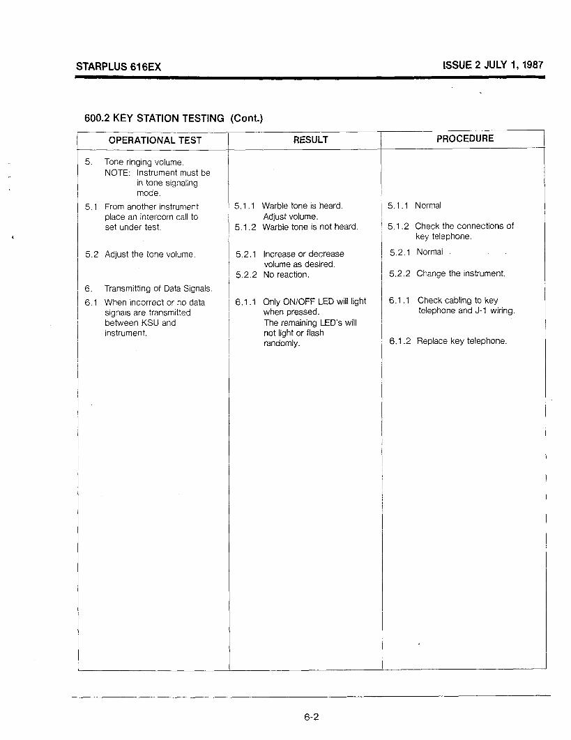
STARPLUS 616EX ISSUE 2 JULY I, 1987
600.2 KEY STATION TESTING (Cont.)
OPERATIONAL TEST
5. Tone ringing volume. NOTE: Instrument must be
in tone signaling mode.
5.1 From another instrument place an intercom call to set under test.
5.2 Adjust the tone volume.
6. Transmitting of Data Signals.
6.1 When incorrect or no data signals are transmitted between KSU and instrument.
RESULT PROCEDURE
5.1 .1 Warble tone is heard. 5.1.1 Normal Adjust volume.
5.1.2 Warble tone is not heard. 5.1.2 Check the connections of key telephone.
5.2.1 Increase or decrease 52.1 Normal volume as desired.
5.2.2 No reaction. , 5.2.2 Change the instrument.
6.1 .l Only ON/OFF LED will light I 6.1 .l Check cabling to key when pressed. telephone and J-l wiring. The remaining LED’s will not light or flash randomly. 6.1.2 Replace key telephone.
,
6-2

STARPLUS 616EX ISSUE 2 JULY I,1987
600.3 INTERCOM FUNCTIONS TEST
OPERATIONAL TEST
Intercom Call
Depress the DSS button for the desired instrument. a. If the called instrument is
a speakerphone and is placed in the handsfree talk back (voice) mode.
If the called station answers by lifting the handset.
Call Pick-Up Lift Handset and depress DSS button for called station. To answer at another station, lift the handset or depress the ON/OFF button. Depress 6 on the dial pad.
T
RESULT 1 PROCEDURE
1 .l .l 1.1.2
1.1.3
1.1.4
1 .1.5
1.1.6
1.1.7
1 .l .a
1 .1.9
ON/OFF lamp lights. DSS lamp of called party is lit. Intercom lamp (HOLD button) of called party is flashing 30 IPM. Busy tone or DND tone is heard.
3 tones are heard (handsfree). Handsfree communication is possible at the called instrument, if it is a speakerphone. HOLD button flashes at called party. Intercom call is not connected. Intercom ringing is heard instead of 3 tones.
1.1.1 OHandsfree conversation at the called instrument is not possible.
1.2. 1 The flashing HOLD lamp of the called instrument lights steadily.
1.2.2 Ring back tone is stopped. 1.2.2 Normal
1.3.a Intercom ringing or CO ringing heard at the called station. Intercom dial tone is heard.
1.3.a Normal
1.3.b 1.3.b Normal
1.3.c Called station returns to idle state. HOLD lamp is extinguished. Intercom conversation between calling instrument and answering station is possible. If answering is not possible.
/ 1 .l.l Normal 1.1.2 Normal
1.1.3 Normal
1 .I .4 If called party is off-hook, in DND mode or not installed; normal.
1.1.5 Normal
1 .1.6 Normal
1 .1.7 Normal
1 .1.8 Consult trouble shooting guide, section 7.
1 .1.9 Confirm whether called station is in P or H mode.
I 1.1.1 OCheck connections of key telephone.
1.1.1 1 Check that called instrument has speakerphone.
1.2.1 Normal
1.3.~ Normal
Normal
Change the instrument.
6-3
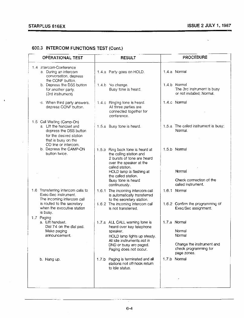
STARPLUS 616EX ISSUE 2 JULY 1,1987
600.3 INTERCOM FUNCTIONS TEST (Cont.) ___
OPERATIONAL TEST RESULT PROCEDURE
1.4 Intercom-Conference a. During an intercom
conversation, depress the CONF button.
b. Depress the DSS button for another party. (3rd instrument)
1.4.a Party goes on HOLD.
1.4.b No change. Busy tone is heard.
1.4.a Normal
1.4.b Normal The 3rd instrument is busy or not installed; Normal.
c. When third party answers, / 1.4.~ Ringing tone is heard. 1.4.~ Normal depress CONF button. All three parties are
connected together for conference.
1.5 Call Waiting (Camp-On) a. Lift the handset and
depress the DSS button for the desired station that is busy on the CO line or intercom.
b. Depress the CAMP-ON button twice.
1 .6 Transferring intercom calls to Exec-Set instrument. The incoming intercom call is routed to the secretary when the executive station is busy.
1.7 Paging a. Lift handset.
Dial 74 on the dial pad. Make paging announcement.
b. Hang up.
1.5.a Busy tone is heard. , 1.5.a ‘The called instrument is busy; Normal.
1.5.b Ring back tone is heard at 1.5.b Normal the calling station and 2 bursts of tone are heard over the speaker at the called station. HOLD lamp is flashing at Normal the called station. Busy tone is heard Check connection of the continuously. called instrument.
1.6.1 The incoming intercom call 1.6.1 Normal is automatically transferred to the secretary station.
1.6.2 The incoming intercom call 1.6.2 Confirm the programming of is not transferred. ExeciSec assignment.
1.7.a ALL CALL warning tone is 1.7.a Normal heard over key telephone speaker. Normal HOLD lamp lights up steady. Normal All idle instruments not in DND or busy are paged. Change the instrument and Paging does not occur. check programming for
page zones.
1.7.b Paging is terminated and all 1.7.b Normal stations not off-hook return to idle status.
6-4
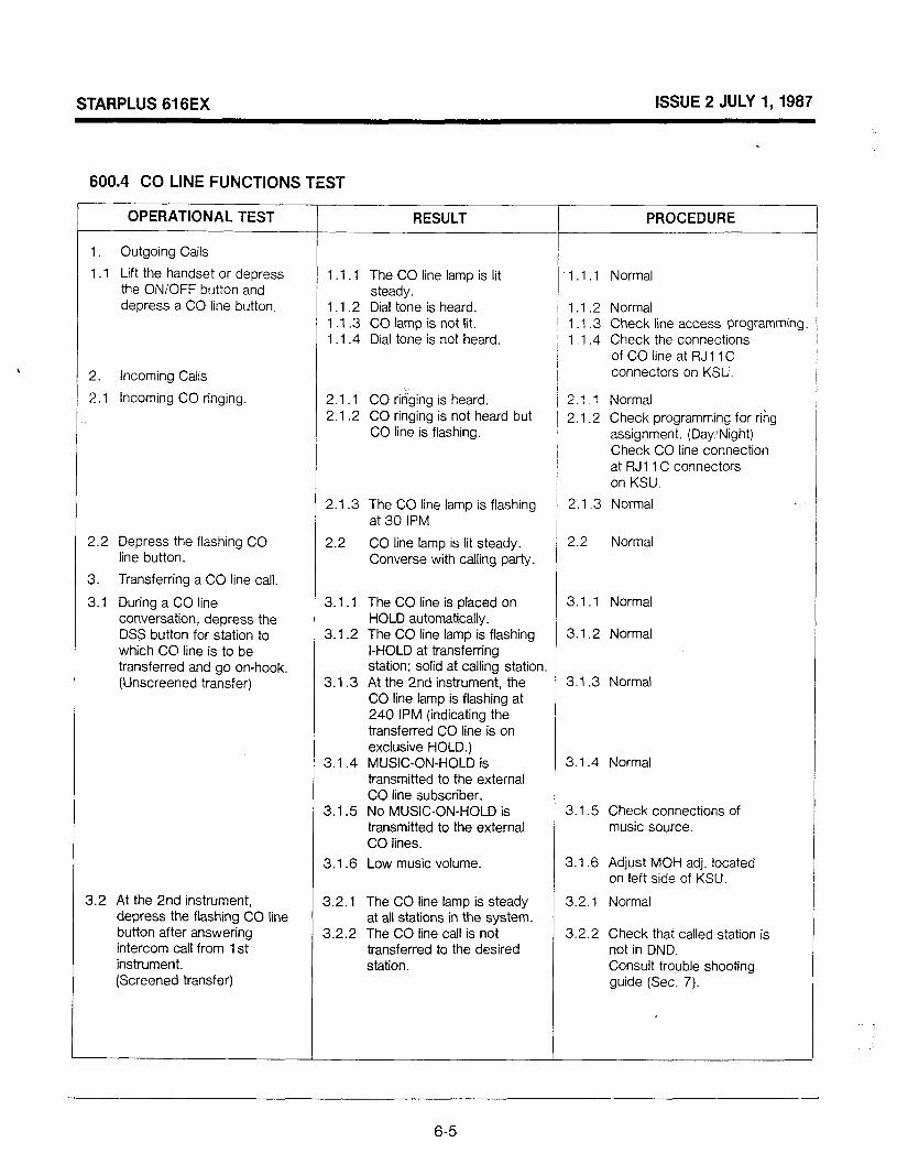
STARPLUS 616EX ISSUE 2 JULY 1,1987
^\
600.4 CO LINE FUNCTIONS TEST
OPERATIONAL TEST RESULT PROCEDURE
1. Outgoing Calls
1.1 Lift the handset or depress the ON/OFF button and depress a CO line button.
2. Incoming Calls
2.1 Incoming CO ringing.
1 .l .1 The CO line lamp is lit 1 .l .l Normal steady.
1 .l .2 Dial tone is heard. / 1.1.2 Normal 1 .1 .3 CO lamp is not lit. I 1 .l .3 Check line access Programming 1 .1.4 Dial tone is not heard. ) 1 .1.4 Check the connections
of CO line at RJl 1 C I 1 connectors on KSU. I
2.1.1 CO ringing is heard. i 2.1.1 Normal 2.1 .2 CO ringing is not heard but
CO line is flashing. / 2.1.2 Check programming for ring
assignment. (Day.‘Night) Check CO line connection at RJl 1 C connectors on KSU.
2.2 Depress the flashing CO line button.
3. Transferring a CO line call.
3.1 During a CO line conversation, depress the DSS button for station to which CO line is to be transferred and go on-hook. [Unscreened transfer)
2.1 .3 The CO line lamp is flashing at 30 IPM
1 2.1.3 Normal
2.2 CO line lamp is lit steady. 2.2 Normal Converse with calling party.
3.1.1 The CO line is placed on 3.1 .1 Normal HOLD automatically.
3.1 .2 The CO line lamp is flashing 3.1.2 Normal I-HOLD at transferring station; solid at calling station.
3.1.3 At the 2nd instrument, the 3.1.3 Normal CO line lamp is flashing at 240 IPM (indicating the transferred CO line is on exclusive HOLD.)
3.1.4 MUSIC-ON-HOLD is 3.1.4 Normal transmitted to the external CO line subscriber.
3.1.5 No MUSIC-ON-HOLD is 3.15 Check connections of transmitted to the external music source. CO lines.
3.1.6 Low music volume. 3.1.6 Adjust MOH adj. located on left side of KSU.
3.2 At the 2nd instrument, depress the flashing CO line button after answering intercom call from 1 st instrument. (Screened transfer)
3.2.1 The CO line lamp is steady at all stations in the system.
3.2.2 The CO line call is not transferred to the desired station.
3.2.1 Normal
3.2.2 Check that called station is not in DND. Consult trouble shooting guide (Sec. 7).
6-5
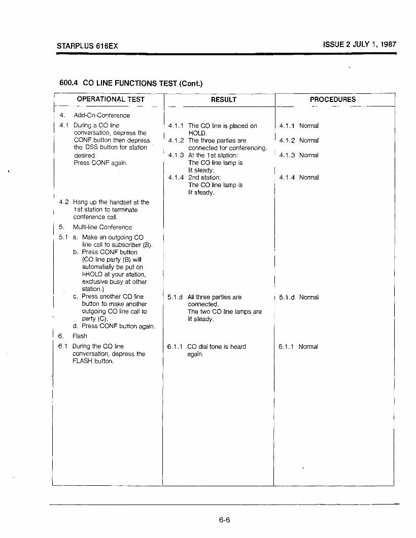
STARPLUS 616EX ISSUE 2 JULY 1,1987
600.4 CO LINE FUNCTIONS TEST (Cont.)
OPERATIONAL TEST RESULT PROCEDURES
4. Add-On-Conference
4.1 During a CO line conversation, depress the CONF button then depress the DSS button for station desired. Press CONF again.
4.1 .l The CO line is placed on HOLD.
4.1.2 The three parties are connected for conferencing.
4.1.3 At the 1 st station: The CO line lamp is lit steady.
4.1.4 2nd station: The CO line lamp is lit steady.
4.1 .l Normal
4.1.2 Normal
4.1.3 Normal
4.1.4 Norma!
4.2 Hang up the handset at the 1 St station to terminate conference call.
5. Multi-line Conference
5.1 a. Make an outgoing CO line call to subscriber (B).
b. Press CONF button (CO line party (B) will automatially be put on I-HOLD at your station, exclusive busy at other station.)
c. Press another CO line button to make another outgoing CO line call to Party (C).
d. Press CONF button again.
6. Flash
5.1 .d All three parties are connected. The two CO line lamps are lit steady.
5.1 .d Normal
6.1 During the CO line conversation, depress the FLASH button.
6.1 .l CO dial tone is heard again.
6.1 .l Normal
6-6
STARPLUS 616EX ISSUE 2 JULY 1,1987
700 MAINTENANCE AND TROUBLESHOOTING
700.1 GENERAL INFORMATION
700.2 INTRODUCTION
This section provides common maintenance, trouble shooting and repair instructions for the STARPLUS Key Telephone System. It is advisable to use the latest issue manual and supporting documentation whenever possible.
< The 616 architecture is designed such that all solid state circuitry is enclosed in the KSU. There are no modular or replaceable type printed circuit cards located inside the KSU. Therefore, the KSU unit is “sealed” and the cover should not be removed. Fault isolation to the replaceable units (KSU, Key Telephones, or external devices) requires no special knowledge of solid state electronics or microprocessor programming techniques. The 6 16 system requires no involved or complicated mechanical procedures for installation or removal of peripherals. In troubleshooting, all cables, plugs and attaching hardware should be removed and installed carefully.
700.3 PREVENTIVE MAINTENANCE
A systematic preventive maintenance program is essential to reduce the possibility of system failures. The routines for general type servicing, which includes cleaning and inspecting, should be done on an annual schedule. More frequent intervals are required where extreme environmental conditions exist such as high temperature, humidity, dust, etc. These routines should include, but are not limited to, the following:
- Hardware and cabling. Check for general mechanical integrity, loose or broken wires, plugs, or connectors. Tighten or repair as necessary.
- KSU. Inspect air vents located in front and on top of the KSU cabinet for unrestricted air passage.
- MDF/cabling. Inspect the MDF for loose wires, obstructions, dust and dirt.
700.4 TEST EQUIPMENT AND TOOLS
The following test equipment and tools are necessary in performing maintenance and repair on the 6 16 system.
-Voltmeter.
- DTMF/dial pulse hand held test telephone.
- Standard telephone repairman’s hand tools.
700.5 SPARE PARTS
The trouble shooting and repair instructions are based on the assumption that spare Key Telephones and KSU are available to the repairman either on-site or at a central warehouse/storeroom location. In addition, spare fuses, jacks, wire and terminal blocks should be available.
700.6 FIELD SERVIDE ENGINEERING
The installation, trouble shooting and repair are described in detail within this manual. However, many field type questions such as application requirements and trouble shooting assistance, arise which require support. Such services are available through Field Service.
700.7 TROUBLE SHOOTING PROCEDURES
700.8 FAULT CLASSIFICATION
Reported problems comes from a variety of people under differing conditions, therefore all trouble reports should be thoroughly examined so that the exact problem is understood. Do not always suspect the 616 equipment. Be sure to check external interface equipment, such as the MDF, inter- connection points, cabling, central office, or programming. To help isolate a fault from the reported description, the following information should be
A)
investigated’to further define the fault source.
Were any changes made recently to the customer data base assignments that could cause the problem?
B)
C)
D)
E)
Were any changes made recently to cabling that could cause the problem?
Is the trouble condition associated with one circuit, a particular section or sections of circuits (i.e. CO lines, stations) or common to all circuits?
Is the trouble intermittent or continuous?
Could the trouble be caused by “cross symptoms” such that two failures mask the symptom associated with a particular fault?
7-1

STARPLUS 616EX ISSUE 2 JULY I,1987
700.9 SYSTEM FAILURES
Various problems will affect the entire system. These are normally related to power failures, central processor failures, or memory failures. Where central processor or memory failures occur, the KSU must be replaced. When loss of power occurs, steps can be taken to localize the problem.
700.10 POWER FAILURES
The loss of commercial power will shut the system down, unless external battery back-up is provided. This loss of power could come from tripped circuit breakers, AC cords unplugged, or a fuse blown. When a power failure occurs, test for voltage working toward the source. The power monitor LED will remain lit when power is present. Since the processor or power failure will cause switch over to the power failure telephone, the LED should be used to determine whether it is a power failure or processor failure. It can be seen through the bottom air vents located on the front cover.
700.11 KEY TELEPHONE FAILURES
The following statements should be considered when isolating and categorizing key telephone failures:
Is the reported fault:
- Present on one telephone only? Check the wiring, programming, telephone and KSU. Move the telephone to a working position to eliminate telephone failure.
- Common to station numbers in pairs (l-2, 3-4, 5-6, etc.) Check the wiring polarity and KSU.
- Common to all station numbers? Check the programming and KSU.
-Associated with a key telephone that was recently moved? Check the wiring, programming, telephone and KSU.
- Associated with programming changes recently made? (Ringing, CO line access, etc.) Check for proper and accurate programming.
- Occurring intermittently? Set up a test to duplicate the problem.
- Accompanying a software feature? Test the feature operation, programming and KSU.
700.12 COlPBX LINE FAILURES
Problems with CO/PBX lines can be isolated and categorized by the following statements:
Is the reported fault:
- Present on one CO line only? Check the affected CO Line, wiring, plug connections and KSU.
-Common to two or more CO lines? Check the CO lines, wiring and KSU.
- Associated with a Key Telephone? . Check the programming, telephone and KSU.
- Associated with signaling (DTMF, dial pulse)? Check the programming, CO line and KSU.
- Associated with CO incoming ringing? Check the programming and KSU.
- Occurring intermittently? Set up test to duplicate problem. Once the problem can be duplicated, check affected programming, telephone, CO line or KSU.
700.13 FEATURE OPERATION FAILURES
All operational features are controlled by software and specific data base assignments. Most features are provided exclusively by the software. However, others require supporting equipment. For this reason, data base assignments should be checked before corrective maintentance is performed. Also check for proper usage by the customer, as feature failures are often the fault of the user. Features that utilize supporting equipment could have faulty equipment. This should be checked.
The following is a list of features that use additional equipment:
7’-2

.
L I
-l---
r
CP
U
MO
DU
LE
1.
CP
U
2.
RA
M’S
3.
R
OM
’S
4.
DE
CO
DE
5.
C
LOC
K
6.
RE
CO
VE
RY
RE
LAY
D
RIV
ER
I~
----
----
-~
LOU
D
BE
LL
CTL
SE
LtC
T I
r C
MO
S
SW
ITC
H
4 , 1
INTE
RC
OM
1
CH
AN
NE
LS
, C6
----
----
----
,6
1 R
ING
D
ETE
CT
1 i
1
1 1
VO
ICE
S
IGN
AL
3 C
HA
NN
EL
PA
RA
LLE
L IN
/OU
T PI
0
SE
LEC
T D
ATA
C
OM
MU
NIC
ATI
ON
P
ATH
M
ULT
IPLE
XE
R
I 16
K
EY
S
TATI
ON
IN
TER
FAC
ES
I
STA
R P
LUS
SY
STE
M B
LOC
K D
IAG
RA
M
FIG
UR
E 7
.1
6C0
LIN
E
INTE
RFA
CE
S
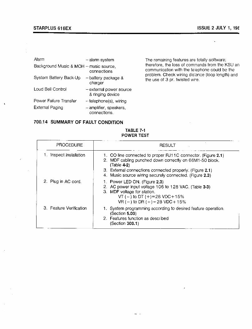
STARPLUS 616EX ISSUE 2 JULY 1,1987
Alarm - alarm system
Background Music & MOH - music source, connections
System Battery Back-Up -battery package & charger
Loud Bell Control -external power source & ringing device
Power Failure Transfer -telephone(s), wiring
External Paging -amplifier, speakers, connections.
The remaining features are totally software; therefore, the loss of commands from the KSU and communication with the telephone could be the problem. Check wiring distance (loop length) and the use of 3 pr. twisted wire.
700.14 SUMMARY OF FAULT CONDITION
TABLE 7-I POWER TEST
PROCEDURE RESULT
1 . Inspect Installation 1. CO line connected to proper RJl 1 C connector. (Figure 2.1) 2. MDF cabling punched down correctly on 66Ml-50 block.
(Table 4-2)
2. Plug in AC cord.
3. Feature Verification
3. External connections connected properly. (Figure 2.1) 4. Music source wiring securely connected. (Figure 2.3)
1. Power LED ON. (Figure 2.3) 2. AC power input voltage 106 to 128 VAC. (Table 3-3) 3. MDF voltage for station.
VT(-)toDT(+)=28VDC+15% VR(-)toDR(+)=28VDC+15%
1. System programming according to desired feature operation. (Section 5.00)
2. Features function as described (Section 300.1)

STARPLUS 6‘16EX ISSUE 2 JULY 1,1987
SP6 1600-00 SP6 1600-O 1 SP6 16 1 O-00 SP6161 O-44 SP6 16 1 O-54 SP6161 O-60 SP61612-00 SP61612-44 SP61612-54 SF61 612-60 SP61614-00 SP61614-44 SP61614-54 SP61614-60 SP61616-44 SP61620-01 SP61620-02 SP61’640-00 SP6 1640-44 SP61650-00 SP6 1652-00 SP61654-00
. SP6 1660-00 SP6 1660-44 SP61660-54 SP61660-60 SP61662-00 SP6 1630-44 SP61666-54 SP6 1666-60 SP61664-00 SP61664-01 VC61101
PART NUMBERS FOR THE STARPLUS 6i6EX
616EX BASIC KSU 616EX ENHANCED KSU BASIC KEY TELEPHONE - BLACK BASIC KEY TELEPHONE - ASH BASIC KEY TELEPHONE - GRAY BASIC KEY TELEPHONE-BURGUNDY ENHANCED KEY TELEPHONE - BLACK ENHANCED KEY TELEPHONE- ASH ENHANCED KEY TELEPHONE-GRAY ENHANCED KEY TELEPHONE - BURGUNDY EXECUTIVE KEY TELEPHONE - BLACK EXECUTIVE KEY TELEPHONE - ASH EXECUTIVE KEY TELEPHONE - GRAY EXECUTIVE KEY TELEPHONE - BURGUNDY PHONE BOX- ASH PROGRAM MODULE I PROGRAM MODULE II WALL MOUNT KIT - BLACK WALL MOUNT KIT- ASH STARPLUS 616EX INSTALLATION MANUAL STARPLUS BASIC STATION USER GUIDE STARPLUS ENHANCED/EXECUTIVE STATION USER GUIDE REPLACEMENT HANDSET - BLACK REPLACEMENT HANDSET - ASH REPLACEMENT HANDSET - GRAY REPLACEMENT HANDSET- BURGUNDY BUl-i-ON CAPS (1 RED, 9 CLEAR) MINI PRINTER - ASH 12 FOOT HANDSET CORD - GRAY 12 FOOT HANDSET CORD - BURGUNDY BtiNK DESIGNATION TABS FOR BASIC TELEPHONE BLANK DESIGNATION TABS FOR ENtiANCED TELEPHONE BAll-ERY BACKUP UNIT


