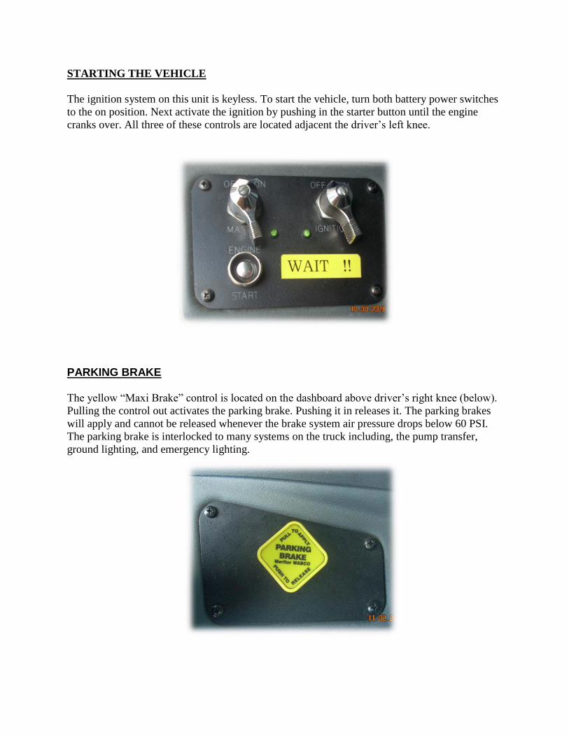
STARTING THE VEHICLE The ignition system on this unit is keyless. To start the vehicle, turn both battery power switches
to the on position. Next activate the ignition by pushing in the starter button until the engine
cranks over. All three of these controls are located adjacent the driver’s left knee.
PARKING BRAKE
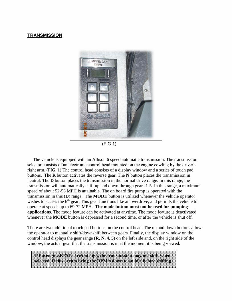
The yellow “Maxi Brake” control is located on the dashboard above driver’s right knee (below).
Pulling the control out activates the parking brake. Pushing it in releases it. The parking brakes
will apply and cannot be released whenever the brake system air pressure drops below 60 PSI.
The parking brake is interlocked to many systems on the truck including, the pump transfer,
ground lighting, and emergency lighting.
TRANSMISSION
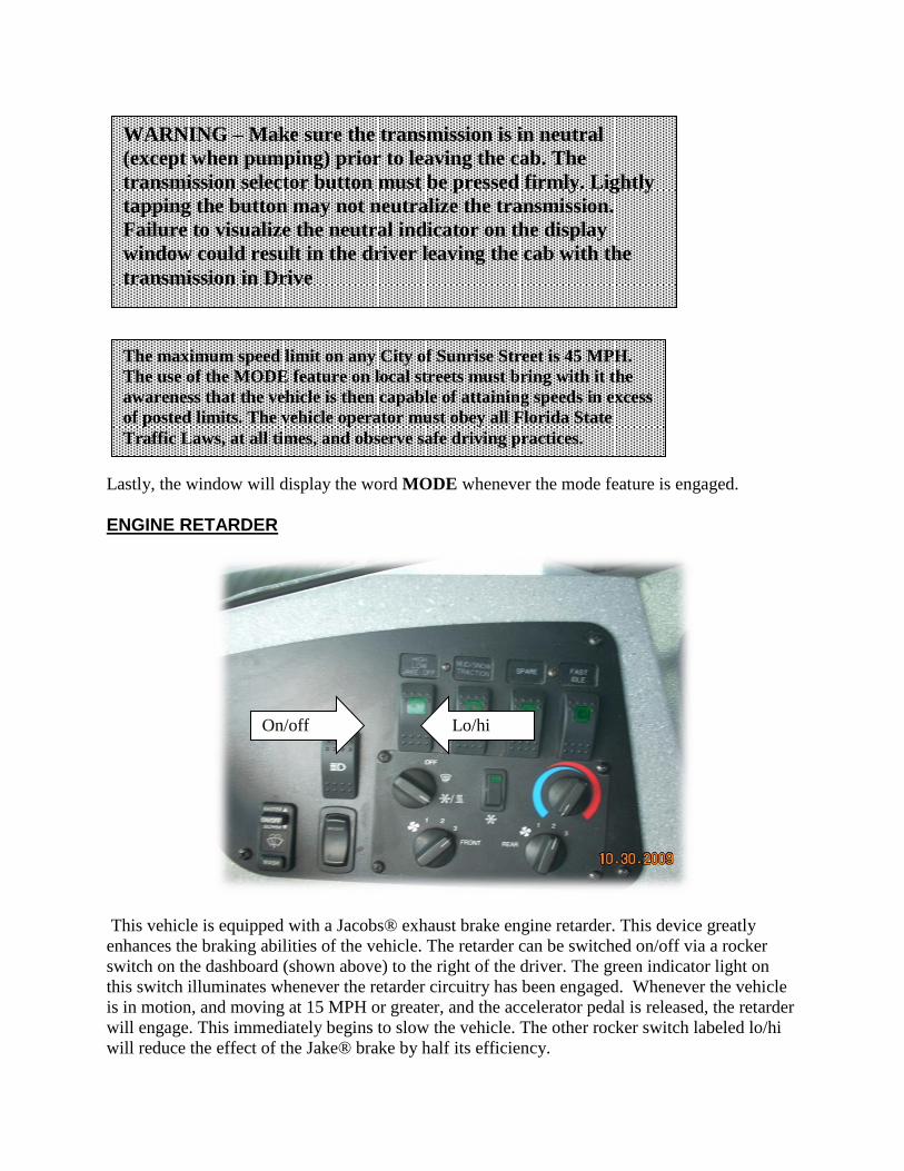
(FIG 1)
The vehicle is equipped with an Allison 6 speed automatic transmission. The transmission
selector consists of an electronic control head mounted on the engine cowling by the driver’s
right arm. (FIG. 1) The control head consists of a display window and a series of touch pad
buttons. The R button activates the reverse gear. The N button places the transmission in
neutral. The D button places the transmission in the normal drive range. In this range, the
transmission will automatically shift up and down through gears 1-5. In this range, a maximum
speed of about 52-53 MPH is attainable. The on board fire pump is operated with the
transmission in this (D) range. The MODE button is utilized whenever the vehicle operator
wishes to access the 6th gear. This gear functions like an overdrive, and permits the vehicle to
operate at speeds up to 69-72 MPH. The mode button must not be used for pumping
applications. The mode feature can be activated at anytime. The mode feature is deactivated
whenever the MODE button is depressed for a second time, or after the vehicle is shut off. There are two additional touch pad buttons on the control head. The up and down buttons allow
the operator to manually shift/downshift between gears. Finally, the display window on the
control head displays the gear range (R, N, 4, 5) on the left side and, on the right side of the
window, the actual gear that the transmission is in at the moment it is being viewed.
If the engine RPM’s are too high, the transmission may not shift when
selected. If this occurs bring the RPM’s down to an idle before shifting
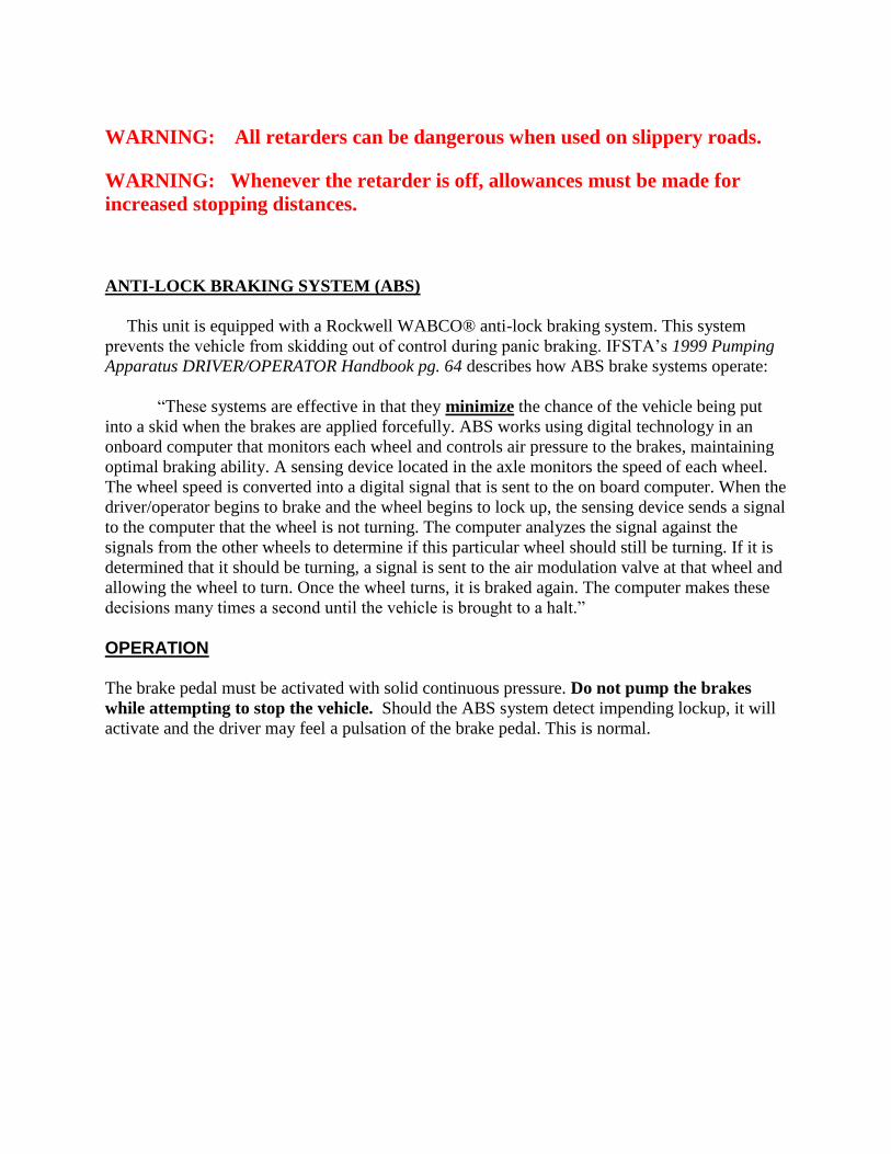
Lastly, the window will display the word MODE whenever the mode feature is engaged. ENGINE RETARDER
This vehicle is equipped with a Jacobs® exhaust brake engine retarder. This device greatly
enhances the braking abilities of the vehicle. The retarder can be switched on/off via a rocker
switch on the dashboard (shown above) to the right of the driver. The green indicator light on
this switch illuminates whenever the retarder circuitry has been engaged. Whenever the vehicle
is in motion, and moving at 15 MPH or greater, and the accelerator pedal is released, the retarder
will engage. This immediately begins to slow the vehicle. The other rocker switch labeled lo/hi
will reduce the effect of the Jake® brake by half its efficiency.
WARNING – Make sure the transmission is in neutral
(except when pumping) prior to leaving the cab. The
transmission selector button must be pressed firmly. Lightly
tapping the button may not neutralize the transmission.
Failure to visualize the neutral indicator on the display
window could result in the driver leaving the cab with the
transmission in Drive
The maximum speed limit on any City of Sunrise Street is 45 MPH.
The use of the MODE feature on local streets must bring with it the
awareness that the vehicle is then capable of attaining speeds in excess
of posted limits. The vehicle operator must obey all Florida State
Traffic Laws, at all times, and observe safe driving practices.
On/off Lo/hi
WARNING: All retarders can be dangerous when used on slippery roads.
WARNING: Whenever the retarder is off, allowances must be made for
increased stopping distances.
ANTI-LOCK BRAKING SYSTEM (ABS) This unit is equipped with a Rockwell WABCO® anti-lock braking system. This system
prevents the vehicle from skidding out of control during panic braking. IFSTA’s 1999 Pumping
Apparatus DRIVER/OPERATOR Handbook pg. 64 describes how ABS brake systems operate:
“These systems are effective in that they minimize the chance of the vehicle being put
into a skid when the brakes are applied forcefully. ABS works using digital technology in an
onboard computer that monitors each wheel and controls air pressure to the brakes, maintaining
optimal braking ability. A sensing device located in the axle monitors the speed of each wheel.
The wheel speed is converted into a digital signal that is sent to the on board computer. When the
driver/operator begins to brake and the wheel begins to lock up, the sensing device sends a signal
to the computer that the wheel is not turning. The computer analyzes the signal against the
signals from the other wheels to determine if this particular wheel should still be turning. If it is
determined that it should be turning, a signal is sent to the air modulation valve at that wheel and
allowing the wheel to turn. Once the wheel turns, it is braked again. The computer makes these
decisions many times a second until the vehicle is brought to a halt.” OPERATION
The brake pedal must be activated with solid continuous pressure. Do not pump the brakes
while attempting to stop the vehicle. Should the ABS system detect impending lockup, it will
activate and the driver may feel a pulsation of the brake pedal. This is normal.
CAB SWITCHES and PUMP SHIFT
FIG 1
The switch consoles located in the driver’s position are all rocker switches (FIG 1). To activate
or deactivate the desired listed function simply toggle the switch, the green light should
illuminate when in the on position. These panels control various emergency lighting as well as
scene lighting.
Class One® Total System Manager™
The Spartan /Saulsbury are equipped with a Class One® Total System Manager™. This device
manages the entire 12 volt electrical system via an on board computer per NFPA 1901
requirements.
All the emergency warning lights are controlled via an emergency/master sequencer (FIG
1). It takes several seconds for all the lights to activate. Similarly, it takes several seconds
for the lights to sequence down. Do not shut the vehicle off until all the lights have
sequenced off. Doing otherwise can damage the circuitry.
Whenever the Parking Brake is on – All forward facing white lights will shut down including the wigwag headlights
The scene lights will not work unless the parking brake is on
The underbody ground lighting will not work unless the Parking Brake is ON.
Compartment lights are always on at night whenever the parking brake is on.
Whenever system voltage drops BELOW 11.9 volts DC, the system manager™ will
automatically engage the high idle (1200 rpm) until such time that the system voltage is
above 13 volts DC at which time it will automatically cut out. The parking brake must be
on for high idle to work.
Master/sequencer
FEDERAL SIGNAL CORPORATION® TRAFFIC MASTER™
The Federal Signal Corporation® Traffic Master™ is the directional traffic light bar located on
the rear of the apparatus. The electronic control head for the Traffic Master™ is located on the
engine cowling near the right arm of the driver/operator. This device allows the driver/operator
to choose a light pattern to direct traffic to the LEFT, RIGHT, and SPLIT out both sides from the
center, and FLASH which places the Traffic Master™ into an alternating wigwag pattern for
additional rear warning. There is also FAST/LOW feature
OIL and FLUID CHECKS
The daily oil checks can be accomplished by opening the access door which in this case is the
front grill. Within this door, the driver/operator will be able to check the transmission, oil, power
steering, and windshield wiper fluid levels, as well as fill the appropriate fluids. If further access
to the engine compartment is needed, the apparatus must be taken to the city garage.
CLASS 1® (CAPTAIN™) ENGINE GOVENOR CONTROL
The Captain operates in one of two modes, Pressure or RPM. In pressure mode the Captain
maintains a constant pump discharge pressure. The discharge pressure is monitored and
compared to the selected pressure setting, the engine RPM is varied to keep the discharge
pressure at the selected setting. In RPM mode the Captain maintains a constant engine RPM. The
pump discharge pressure is monitored and can vary but as a safety feature it will be limited to an
increase of 30 PSI. If the discharge pressure increases 30 PSI the governor will automatically
lower the engine RPM to prevent a high-pressure surge.
RPM (throttle) mode - The driver operator can switch to the RPM mode when pressure surges
cause the pump to keep returning to an idle. When using the Throttle (RPM) mode, the operator
can either watch the RPM display on the engine status monitor to the right of the rotating throttle
or watch the master pump discharge gauge to the right of the governor while rotating the throttle
control knob. PSI (pressure) Mode – The pressure mode will adjust engine speed to maintain a selected
pressure. Regardless of whether incoming pressure changes or discharges are opened and shut,
the pressure governor will maintain the selected PSI. When using the pressure mode the operator
should watch the master pump discharge gauge.
Mode Selection – After engaging the pump the Class 1® Captain ™ head will display the word
MODE. To activate the unit, the operator pushes the pressure switch of desired mode once. Cavitation Protection Feature – The pressure governor includes a cavitation protection feature,
which protects the pump, plumbing, and firefighters from sudden water surges, ingestion of large
amounts of air, or loss of supply pressure. The mode selector must be in the PSI mode for
this feature to be active and the pump pressure must be above 40 PSI. If the water supply is
reduced or interrupted, the governor will first attempt to increase pressure by increasing the
engine speed. If the pump discharge pressure remains less than 25 PSI for more than 5 seconds,
the engine speed will automatically return to an idle. If it is apparent that air or a temporary reduction of suction pressure has been or will be
introduced into the pump, it may be desirable to temporarily switch from the PSI mode to
the RPM mode to reduce the likelihood of sudden RPM changes and the automatic
shutdown of lines due to the anti-cavitation feature. System Shutdown- Pushing the red idle button in for more than one second will cause the
engine governor to return to an idle speed. The red idle button can and should be used to return
the engine speed to idle when operating in low or no water flow conditions. It should not be
used when flowing large amounts of water as this may cause a water hammer. Use the
inc/dec buttons to reduce pressure to reduce this occurrence. Once the red idle button has been activated, the governor leaves the mode sequence. The
MODE button must be depressed again and a mode type selected in order to restore
control of the pump. The Class 1® Engine Status Center also features remote engine monitoring for the following:
Engine oil pressure
Engine water temperature
Engine RPM
Battery voltage
OPERATING THE ON-BOARD GENERATOR
Vehicle 304 is equipped with a 5000 SX Honda four-cycle gasoline fueled air-cooled generator.
The generator is located in the 2nd compartment D/O side of the apparatus. The generator
supplies the wire reel, 120-volt outlets, and various scene lights.
The generator draws its fuel supply from an integrated 4.5-gallon fuel tank (gasoline) and has a
1.2-quart oil reservoir for 10W-30 or 10W-40 oil. The generator weighs 175 lbs. without fluids.
A circuit breaker box is located in the pump panel compartment. This box regulates and controls
electrical power coming from the generator. There is a separate GFI circuit breaker for each of
the six power branches.
NOTE: Two additional 120 V duplex outlet boxes are located in the ALS compartment. These
power outlets do not run off the generator. It is wired to the shoreline connection for on board
charging of ALS equipment.
LADDER STORAGE
The ladder storage for unit 304 is located on the hydraulic ladder rack on top of the apparatus.
The control panel is located on the rear of the apparatus. To operate follow these 3 steps:
1. Turn batteries on
2. Turn power switch to on
3. Toggle switch to desired position and hold.
The ladder rack contains the following ladders:
24 foot extension ladder
14 foot roof ladder with hooks
10 foot folding straight ladder
Care should be taken when storing and retrieving these ladders due to their location.
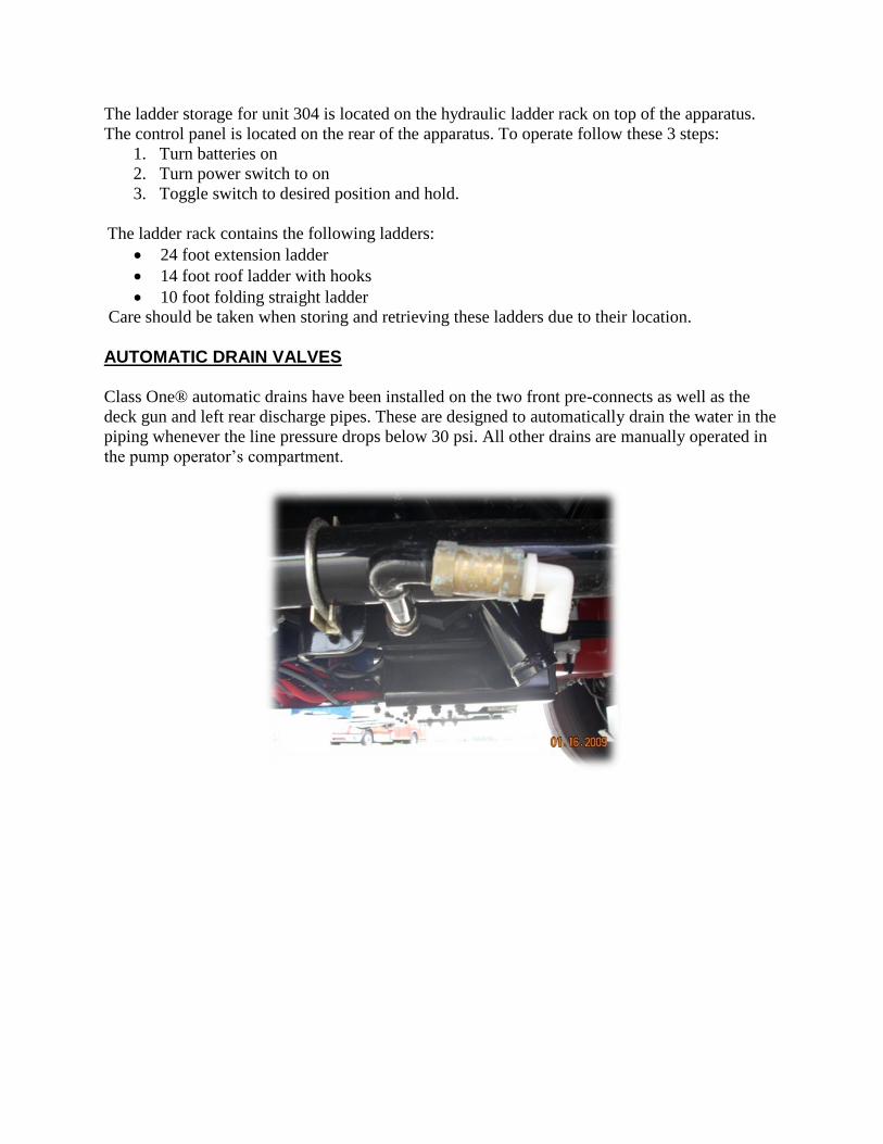
AUTOMATIC DRAIN VALVES Class One® automatic drains have been installed on the two front pre-connects as well as the
deck gun and left rear discharge pipes. These are designed to automatically drain the water in the
piping whenever the line pressure drops below 30 psi. All other drains are manually operated in
the pump operator’s compartment.
PUMP PANEL
The photo above is the actual layout of all switches and controls on unit 304. This panel was
designed to mimic the current pump panels as much as possible to lessen the learning curve.
There are a few changes in control features; however, these controls have been explained
thoroughly in this manual. The rear discharge configuration below also follows our current lay
outs very closely.
Master intake override
Auxiliary intake
CAB TILT
Unit #304’s cab tilt cord/controller is kept @ city garage. In the event that the cab needs to be
tilted the unit will be taken to the garage. The plug for the tilt controller is in the front
compartment on the officers side (FIG 1). Unit #304 is also equipped with a manual cab tilt (FIG
2). The lever extension is located under the officer seat compartment. The actual manual pump is
between the cab and the front compartment on the D/O side of the apparatus.
(FIG 1)
NOTE: This handle is only to be utilized in the failure of the primary pump that tilts the
cab.
(FIG 2)
Lever extension
Controller port
FOAM SYSTEM Unit #304 is equipped with an AKRON® 95 GPM bypass eductor foam system. This will allow
the 30 gallons of on board foam to be proportioned and dispensed through the FRONT 1-3/4”
BUMPER CROSS LAY ONLY. To produce foam, the operator merely opens the tank to pump,
open the eductor valve (pull), open the foam tank suction (rotate), and lastly sets the foam
metering dial to the proper percentage and charges the front discharge line to 200 psi.
Additionally, unit #304 has been equipped with an AKRON® off truck access kit. This kit
allows foam to be drawn into the on board foam system from a source other than the on board
tank (5 gallon jug). To use this function follow the steps described below.
Connect the 6 foot off truck suction hose to the off truck screw on connection on the
pump panel.
Open tank to pump
Open the eductor as described on the previous page (fig 1)
Pull to open
Leave the on-board foam tank closed
Open the auxiliary foam inlet valve
Set the foam proportioner
Set #1 cross lay @ 200 psi Whenever either foam supply source is utilized, the foam system must be flushed for 3 minutes
at 100 psi. To accomplish this, the foam tank valve is closed, the flush valve opened, and the
eductor valve opened.
Should it ever become necessary to drain the foam tank, a foam solution drain valve is located
along the drain valve panel under the pump panel.
Complete operating instructions for the foam system are located on the pump panel by the
metering valve. All foam control valves are color-coded yellow. MASTER INTAKE RELIEF VALVE (MIV) Unit #304 is equipped with a Hale® Master Intake Valve™. The MIV is located on the 6” rear
pump intake. The valve is positioned behind the pump panel. The MIV will dump incoming
pressures in excess of 125 PSI. Moreover, by using the electric valve control switch on the upper
right of the pump, the pump operator can open or close the flow of water into the pump. The
MIV pump panel control switch has position indicator lights to indicate the position of the valve.
An air bleeder is located just to the left of the MIV control switch. The air bleeder is used exactly
like the old screw bleeder on the top of the old PIRV. The air bleeder is used to exhaust air from
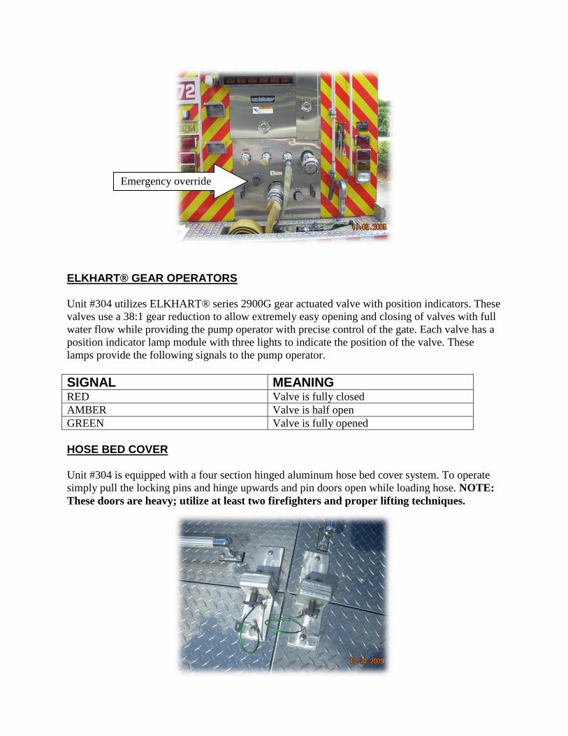
incoming hose lines that could cause cavitation. Above and to the left of the 6” rear pump intake is a 2.5” black knob. This knob is the
EMERGENCY MANUAL OVERRIDE in case of an electrical switch failure. To operate the
override, just turn the knob right to close and left to open (FIG 1).
Foam tank drain
ELKHART® GEAR OPERATORS
Unit #304 utilizes ELKHART® series 2900G gear actuated valve with position indicators. These
valves use a 38:1 gear reduction to allow extremely easy opening and closing of valves with full
water flow while providing the pump operator with precise control of the gate. Each valve has a
position indicator lamp module with three lights to indicate the position of the valve. These
lamps provide the following signals to the pump operator.
SIGNAL MEANING RED Valve is fully closed
AMBER Valve is half open
GREEN Valve is fully opened
HOSE BED COVER Unit #304 is equipped with a four section hinged aluminum hose bed cover system. To operate
simply pull the locking pins and hinge upwards and pin doors open while loading hose. NOTE:
These doors are heavy; utilize at least two firefighters and proper lifting techniques.
Emergency override
TFT® CROSSFIRE™
Unit #304 is equipped with a TFT® Crossfire™ deck gun. This deck gun is mounted to the top
of the apparatus. There is an 18 extend-a-pipe attached to the deck gun for ease of operation.
There is also a ground base stored in the officer’s side rear compartment making the deck gun a
portable unit.
The Crossfire™ can be controlled at the pump panel for quick master stream applications while a
firefighter manually operates the elevation and direction of the master stream nozzle.


![2018 DODGE - barkaucdjr.com€¦ · ESC [5] senses when a vehicle is starting to spin (oversteer) or plow (understeer), and attempts to correct the vehicle s course by automatically](https://static.documents.pub/doc/80x56/5f394e93c959312c2152209a/2018-dodge-esc-5-senses-when-a-vehicle-is-starting-to-spin-oversteer-or-plow.jpg)


