SPEEDTRONIC Mark V Startup Sequence GEEPG A31 Oct01 Taw_StSt_1 1 STARTUP SEQUENCE Power Supply Power supply DC 125V/220V is normal. Power supply AC 115V/230V/400V/6.6KV is normal. All MCC racks are in the position "AUTO". Alarm Messages All critical alarms are cleared and reset. Start Check Signal If A.C. Bus undervoltage is not set L27BN (1) or: A.C. Ext. Bus undervoltage relay is not set L27BZ (1) & Customer permissive to start signal is set L3CP (1) & Compressor inlet thermocouple disagree signal is not set L86TCI (0) & Inlet Guide Vanes (IGV) are in startup pos., 31 < CSGV < 35. L3IGVFLT (0) & Master protective startup lockout signal is not set L86MP (0) Then Start Check signal #0 is set L3STCK0 (1) If Minimum speed signal 14HM (10%) is not set L14HM (0) & Lube oil tank temperature is normal L26QN (1) & Flame detector trouble signal is normal, i.e. no flame signal is set (Alm 059) L28FDSCK (1) & Master select is not in position "OFF" L43O (0) & Control oil pressure switches (63HL-1, -2, -3, 63HG-1, -2, -3) are depressurized and liquid fuel stop valve 20FL-1 is in closed position L86HD (0) Then Start Check signal #1 is set L3STCK1 (1) If Compressor bleed valves #1 to #4 are open, 33CB-1 to 33CB-4 L86CB (0) & Master protective signal "L4" is not set L4Y (1) & Bleed Heat System Not Operational - Trip signal is not set (Master Reset) L3BHFT (0) & Bleed heat feedback normal & Comp Op Limit Bleed Heat Start Ck Perm L3BHSTCK (1) & DLN1 failure to close transfer purge valve is not set L86PGTLO (0) & Ventilation relief damper are not closed L33CPC (0) & Fire protection system trouble condition is not set L30CC (0) & Emergency lube oil pump motor 88QE-1 undervoltage is not set L27QEL (0) & DLN1 failure to close xfer purge valve is not set L86PGTLO (0) & Gen. Breaker earthing switch (Q81) is not closed L4GX (0) Then Start Check signal #2 is set L3STCK2 (1) If Master protective trip signal is not in TRIP condition L4T (0) & Vibration monitoring system (GT and GEN.) is normal (Alm 126) L39VD3 (0) & Loss of Compressor discharge pressure bias signal is not set (Alm 066) L3TFLT (0) Then Start Check signal #3 is set L3STCK3 (1) Common Start Check signal is set L3STCK (1) Note: The normal conditions of the logic signals are set in round brackets ( ) as logic 0 or logic 1.
Transcript
SPEEDTRONIC Mark V Startup Sequence
GEEPG A31 Oct01 Taw_StSt_1 1
STARTUP SEQUENCE
Power Supply
Power supply DC 125V/220V is normal.Power supply AC 115V/230V/400V/6.6KV is normal.All MCC racks are in the position "AUTO".
Alarm Messages
All critical alarms are cleared and reset.
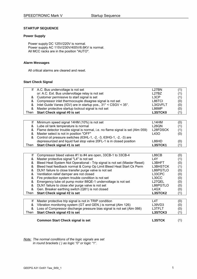
Start Check Signal
If A.C. Bus undervoltage is not set L27BN (1)or: A.C. Ext. Bus undervoltage relay is not set L27BZ (1)
& Customer permissive to start signal is set L3CP (1)& Compressor inlet thermocouple disagree signal is not set L86TCI (0)& Inlet Guide Vanes (IGV) are in startup pos., 31° < CSGV < 35°. L3IGVFLT (0)& Master protective startup lockout signal is not set L86MP (0)
Then Start Check signal #0 is set L3STCK0 (1)
If Minimum speed signal 14HM (10%) is not set L14HM (0)& Lube oil tank temperature is normal L26QN (1)& Flame detector trouble signal is normal, i.e. no flame signal is set (Alm 059) L28FDSCK (1)& Master select is not in position "OFF" L43O (0)& Control oil pressure switches (63HL-1, -2, -3, 63HG-1, -2, -3) are
depressurized and liquid fuel stop valve 20FL-1 is in closed position L86HD (0)Then Start Check signal #1 is set L3STCK1 (1)
If Compressor bleed valves #1 to #4 are open, 33CB-1 to 33CB-4 L86CB (0)& Master protective signal "L4" is not set L4Y (1)& Bleed Heat System Not Operational - Trip signal is not set (Master Reset) L3BHFT (0)& Bleed heat feedback normal & Comp Op Limit Bleed Heat Start Ck Perm L3BHSTCK (1)& DLN1 failure to close transfer purge valve is not set L86PGTLO (0)& Ventilation relief damper are not closed L33CPC (0)& Fire protection system trouble condition is not set L30CC (0)& Emergency lube oil pump motor 88QE-1 undervoltage is not set L27QEL (0)& DLN1 failure to close xfer purge valve is not set L86PGTLO (0)& Gen. Breaker earthing switch (Q81) is not closed L4GX (0)
Then Start Check signal #2 is set L3STCK2 (1)
If Master protective trip signal is not in TRIP condition L4T (0)& Vibration monitoring system (GT and GEN.) is normal (Alm 126) L39VD3 (0)& Loss of Compressor discharge pressure bias signal is not set (Alm 066) L3TFLT (0)
Then Start Check signal #3 is set L3STCK3 (1)
Common Start Check signal is set L3STCK (1)
Note: The normal conditions of the logic signals are setin round brackets ( ) as logic �0� or logic �1�.
SPEEDTRONIC Mark V Startup Sequence
GEEPG A31 Oct01 Taw_StSt_1 2
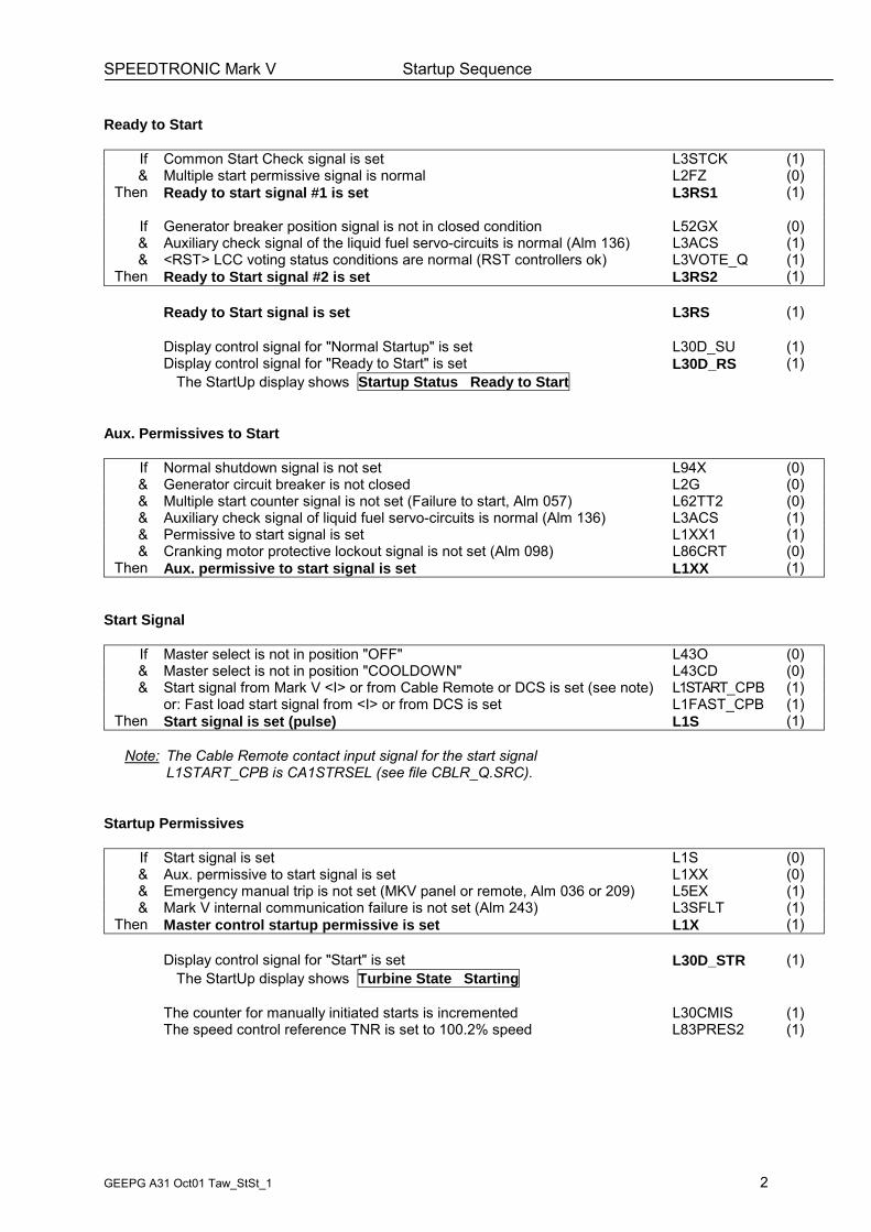
Ready to Start
If Common Start Check signal is set L3STCK (1)& Multiple start permissive signal is normal L2FZ (0)
Then Ready to start signal #1 is set L3RS1 (1)
If Generator breaker position signal is not in closed condition L52GX (0)& Auxiliary check signal of the liquid fuel servo-circuits is normal (Alm 136) L3ACS (1)& <RST> LCC voting status conditions are normal (RST controllers ok) L3VOTE_Q (1)
Then Ready to Start signal #2 is set L3RS2 (1)
Ready to Start signal is set L3RS (1)
Display control signal for "Normal Startup" is set L30D_SU (1)Display control signal for "Ready to Start" is set L30D_RS (1)
The StartUp display shows Startup Status Ready to Start
Aux. Permissives to Start
If Normal shutdown signal is not set L94X (0)& Generator circuit breaker is not closed L2G (0)& Multiple start counter signal is not set (Failure to start, Alm 057) L62TT2 (0)& Auxiliary check signal of liquid fuel servo-circuits is normal (Alm 136) L3ACS (1)& Permissive to start signal is set L1XX1 (1)& Cranking motor protective lockout signal is not set (Alm 098) L86CRT (0)
Then Aux. permissive to start signal is set L1XX (1)
Start Signal
If Master select is not in position "OFF" L43O (0)& Master select is not in position "COOLDOWN" L43CD (0)& Start signal from Mark V <I> or from Cable Remote or DCS is set (see note) L1START_CPB (1)
or: Fast load start signal from <I> or from DCS is set L1FAST_CPB (1)Then Start signal is set (pulse) L1S (1)
Note: The Cable Remote contact input signal for the start signalL1START_CPB is CA1STRSEL (see file CBLR_Q.SRC).
Startup Permissives
If Start signal is set L1S (0)& Aux. permissive to start signal is set L1XX (0)& Emergency manual trip is not set (MKV panel or remote, Alm 036 or 209) L5EX (1)& Mark V internal communication failure is not set (Alm 243) L3SFLT (1)
Then Master control startup permissive is set L1X (1)
Display control signal for "Start" is set L30D_STR (1)The StartUp display shows Turbine State Starting
The counter for manually initiated starts is incremented L30CMIS (1)The speed control reference TNR is set to 100.2% speed L83PRES2 (1)
SPEEDTRONIC Mark V Startup Sequence
GEEPG A31 Oct01 Taw_StSt_1 3
Auxiliary Systems
Fuel gas system
If Fire Indication Trip signal is not set L45FTX (0)Then Fuel gas shut off solenoid valve 20FSX is energized (i.e., valve is open) L20FSX (1)
If Master control startup permissive is set L1X (1)Then Auto vent solenoid valve 20PS can be opened/closed by temp signal FTG L26GLX
If Fuel gas temp. FTG is above value LK26GLX (15degC) L26GLX (1)Then Auto vent solenoid valve 20PS is kept energized (i.e. vent valve is closed) L20PSX (1)
Note: Fuel gas temp. FTG is above min operating temp.Else
If Fuel gas temp. FTG is below value LK26GLX � K26GLX (14degC) L26GLX (0)Then Auto vent solenoid valve 20PS is deenergized (i.e. valve is opened) L20PSX (0)
Note: The vent valve opens to increase fuel gas temp. FTG
Turbine Compartment Ventilation
If All Wheelspace temperature values are below LK69TWW (149degC) L69TWW (1)& Master control startup permissive is set L1X (1)
Then Turbine compartment ventilation permissive signal is set (log. 0) L4BTX (0)
If Turbine compartment ventilation ON signal (1 hour at flame off) is not set L4BTSTP (0)Then The control signal for the turbine compartment ventilation is set L4BT (1)
If The first turbine compartment ventilation fan is selected as lead LAG1BT (0)& The compartment ventilation fan #1 fault signal is not set L30BTX1 (0)
Then Master control signal for the turbine compartment ventilation fan #1 is set L4BTZ1 (1)The selected ventilation fan motor 88BT-1 (or -2) is started.
Note: Master control signal for cooling fan #2 is L4BT2.
SPEEDTRONIC Mark V Startup Sequence
GEEPG A31 Oct01 Taw_StSt_1 4
Auxiliary Systems (cont´d)
COOLDOWN is OFF before Start:
If Master control startup permissive is set L1X (1)Then Master control signal for turb. auxiliaries is enabled (with logic "0") L1Z (0)
Sequence in progress signal is set L3SQ (1)
Display control signal for "Sequence in progress" is set MSG_FLD2The StartUp display shows Start Sequencing Sequence in Progress
Lube oil system:
If Master control signal for turb. auxiliaries is enabled (with logic "0") L1Z (0)Then Aux. control signal for the Auxiliary lube oil pump motor is set (to "0"!) L4QAZ (0)
Master control signal for the Auxiliary lube oil pump motor is set (to "0"!) L4QAZ1 (0)The Auxiliary lube oil pump motor 88QA-1 is started.Auxiliary lube oil pump motor 88QA-1 is running L52QA (1)
If Lube oil pressure is normal (2 of 3) L63QT (0)Then The lube oil mist separator fan motor 88QV-1 is started L4QVZ1A (0)
Generator lift oil pump (Jacking oil pump):
If Lube oil pressure is not low (63QA-2) L63QAL (0)& Speed level signal 14HM is not set L14HM (0)
Then Bearing lift oil pump control signal for motor 88QB-1 is set (log. "0") L4QBZ1 (0)Bearing lift oil pump motor 88QB-1 is started.Bearing lift oil pump motor 88QB-1 is running L52QB (1)
COOLDOWN is ON before Start:
If Cooldown is ON (for K62CD hours, 14hrs, after flames off) L62CD (0)Then Master control signal for turbine auxiliaries is already enabled (with "0") L1Z (0)
Sequence in progress signal is set L3SQ (1)
Display control signal for "Sequence in progress" is already set MSG_FLD2The StartUp display shows Start Sequencing Sequence in Progress
The Auxiliary lube oil pump motor 88QA-1 is running L52QA (1)The lube oil mist Separator fan motor 88QV-1 is running L4QVZ1A (0)The Bearing lift oil pump motor 88QB-1 is running L52QB (1)The Turning gear motor 88TG-1 is running (when normal cooldown is on) L52TG1 (1)
Note: If cooldown had been selected at shutdown condition, 88TG-1 will be off.When 88TG-1 is running, solenoid valve 20TU-1 is energized.
SPEEDTRONIC Mark V Startup Sequence
GEEPG A31 Oct01 Taw_StSt_1 5
Auxiliary Systems (cont´d)
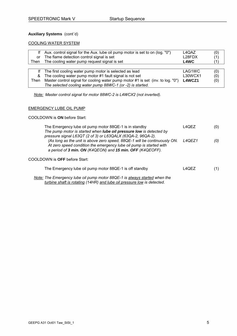
COOLING WATER SYSTEM
If Aux. control signal for the Aux. lube oil pump motor is set to on (log. "0") L4QAZ (0)or The flame detection control signal is set L28FDX (1)
Then The cooling water pump request signal is set L4WC (1)
If The first cooling water pump motor is selected as lead LAG1WC (0)& The cooling water pump motor #1 fault signal is not set L30WCX1 (0)
Then Master control signal for cooling water pump motor #1 is set (inv. to log. "0") L4WCZ1 (0)The selected cooling water pump 88WC-1 (or -2) is started.
Note: Master control signal for motor 88WC-2 is L4WCX2 (not inverted).
EMERGENCY LUBE OIL PUMP
COOLDOWN is ON before Start:
The Emergency lube oil pump motor 88QE-1 is in standby L4QEZ (0)The pump motor is started when lube oil pressure low is detected bypressure signal L63QT (2 of 3) or L63QALX (63QA-2, 96QA-2).
(As long as the unit is above zero speed, 88QE-1 will be continuously ON. L4QEZ1 (0)At zero speed condition the emergency lube oil pump is started witha period of 3 min. ON (K4QEON) and 15 min. OFF (K4QEOFF).
COOLDOWN is OFF before Start:
The Emergency lube oil pump motor 88QE-1 is off standby L4QEZ (1)
Note: The Emergency lube oil pump motor 88QE-1 is always started when theturbine shaft is rotating (14HR) and lube oil pressure low is detected.
SPEEDTRONIC Mark V Startup Sequence
GEEPG A31 Oct01 Taw_StSt_1 6
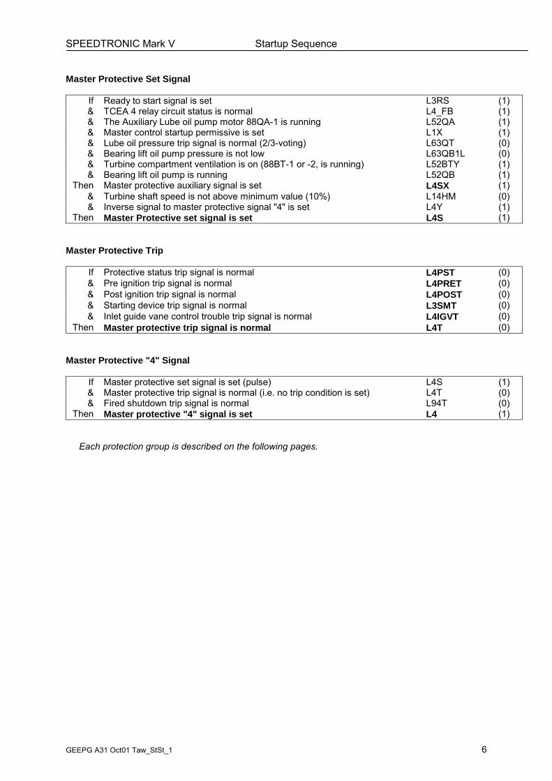
Master Protective Set Signal
If Ready to start signal is set L3RS (1)& TCEA 4 relay circuit status is normal L4_FB (1)& The Auxiliary Lube oil pump motor 88QA-1 is running L52QA (1)& Master control startup permissive is set L1X (1)& Lube oil pressure trip signal is normal (2/3-voting) L63QT (0)& Bearing lift oil pump pressure is not low L63QB1L (0)& Turbine compartment ventilation is on (88BT-1 or -2, is running) L52BTY (1)& Bearing lift oil pump is running L52QB (1)
Then Master protective auxiliary signal is set L4SX (1)& Turbine shaft speed is not above minimum value (10%) L14HM (0)& Inverse signal to master protective signal "4" is set L4Y (1)
Then Master Protective set signal is set L4S (1)
Master Protective Trip
If Protective status trip signal is normal L4PST (0)& Pre ignition trip signal is normal L4PRET (0)& Post ignition trip signal is normal L4POST (0)& Starting device trip signal is normal L3SMT (0)& Inlet guide vane control trouble trip signal is normal L4IGVT (0)
Then Master protective trip signal is normal L4T (0)
Master Protective "4" Signal
If Master protective set signal is set (pulse) L4S (1)& Master protective trip signal is normal (i.e. no trip condition is set) L4T (0)& Fired shutdown trip signal is normal L94T (0)
Then Master protective "4" signal is set L4 (1)
Each protection group is described on the following pages.
SPEEDTRONIC Mark V Startup Sequence
GEEPG A31 Oct01 Taw_StSt_1 7
Protective Status Trip Signal
If Low lube oil pressure trip signal is normal L63QTX (0)& Fire Protection system trip signal is in normal condition (no fire condition) L45FTX (0)& Generator differential protection trip lockout signal is not set L86TGT (0)& TCEA 4 relais circuit status (ext trip) is normal L4_RLYT (0)& Exhaust Pressure High Trip signal is not set L63ETH (0)& Emergency trip pushbutton Mark V panel and remote is not set L5EX (0)& L71PF2H (0)
Then Protective Status Trip #1 is normal L4PSTX1 (1)
If Vibration trip signal is normal L39VT (0)& Startup fuel (gas or liquid) flow excessive trip signal is normal L2SFT (0)& HP speed signal fault of protective speed inputs is not set L12H_FLT (0)& Liquid fuel control fault is not set L3LFLT (0)& On Liquid fuel: Liquid fuel supply pressure low is not set L63FLX1 (0)& On Gas fuel: Gas Scrubber #1 Level High - Trip is not set L71GHHX (0)& Customer trip signal 4CT is not set L4CT (0)
Then Protective Status Trip #2 is normal L4PSTX2 (1)
If HP Conrol speed signal loss trip is not set L12HF (0)& Control speed signal trouble trip signal is not set L12HFD_C (0)& Protective speed signal trouble trip signal is not set L12HFD_P (0)& TCEA HP Overspeed Protection trip signal is not set L12H_P (0)& TCEA HP Excessive Acceleration trip signal is not set L12H_ACC (0)& Gas fuel nozzle purge system trouble trip signal is not set L94PGT (0)
Then Protective Status Trip #3 is normal L4PSTX3 (1)
If Mark V internal communication failure is not set (Alm 243) L3SFLT (0)& Gas control valve "not following reference trip" is not set L86GCVT (0)
Then Protective Status Trip #4 is normal L4PSTX4 (1)
Protective Status Trip signal is not set L4PST (0)
Pre Ignition Trip Signal
If On Liquid fuel: Liquid fuel control fault is not set L3LFLT (0)or On Gas fuel: Gas fuel control fault is not set (for GCV, SRV, GSV, GTV) L3GFLT (0)& Multiple start counter is not set L62TT2 (0)
Then Auxiliary check signal of servo-circuits (liquid or gas fuel) is normal L3ACS (1)
If Emergency lube oil pump motor 88QE-1 undervoltage is not set L27QEL (0)Then Pre Ignition Trip auxiliary signal is normal L4PRETX (0)
& Flame detection signal is not set (before firing) L28FDX (0)Then Pre Ignition Trip signal is normal L4PRET (0)
SPEEDTRONIC Mark V Startup Sequence
GEEPG A31 Oct01 Taw_StSt_1 8
Post Ignition Trip signal
If Control oil press switch signals for liquid fuel (2 of 3) are not low 1) L63HLL (0)& Control oil press switch signals for gas fuel (2 of 3) are not low 1) L63HGL (0)& Lube oil header temp. is not in trip condition (LTTH < K26QT, 79degC) 2) L26QT (0)& Turbine electrical overspeed trip signal is not set L12H (0)& DLN System trouble trip signal is not set (see conditions below) L4DLNT (0)& Compressor press ratio operating limit condition is not set LCPRERR (0)& Bearing metal temperature high high condition is not set (opt.) L30BTT (0)& Bearing drain temperature high high condition is not set (opt.) L30LOT (0)& On gas fuel: Primary gas fuel purge valve is closed L33PGT (0)
Then Post ignition trip auxiliary signal is normal L4POSTX (0)
If Loss of flame trip signal is not set (after firing) L28FDT (0)& High exhaust temperature spread trip signal is not set L30SPT (0)& Exhaust overtemperature trip signal is not set L86TXT (0)& Exhaust thermocouples open trip signal is not set L86TFB (0)& Compressor bleed valves are open during startup (up to 52GX close) L86CBT (0)
Then Post Ignition trip signal is normal L4POST (0)
Note: 1) Conditions are monitored when flame signal is set and firing time is complete.2) Condition is monitored when 14HS speed level is reached.
DLN Trips
If Alarm 311: "FAILURE TO LEAVE SEC TRANSFER-TRIP" is not set L94FX1 (0)& Alarm 314: "FAILURE TO REIGNITE PRIMARY ZONE-TRIP" is not set L94FX2 (0)& Alarm 316: "FAIL TO REIGNITE PRIM-IN SEC L.R.-TRIP" is not set L94FX3 (0)& Alarm 319: "FAILURE TO LEAVE PREMIX XFER - TRIP" is not set L94FX4 (0)
Then DLN-protection circuit 1 ist normal L4DLNT1 (0)
If Alarm 224: "GAS SPLITTER VALVE TROUBLE - TRIP" is not set L86GSVT (0)& Alarm 227: "GAS TRANSFER VALVE TROUBLE - TRIP" is not set L86GTVT (0)& Liqud fuel and Water injection purge common trip signal is not set L86P_FLT (0)& Alarm 066: " LOSS OF COMPR DISCH PRESS BIAS" is not set L3TFLT (0)
Then DLN-protection circuit 2 is normal L4DLNT2 (0)
Then DLN-protection circuit 1 & 2 ist normal L4DLNT (0)
SPEEDTRONIC Mark V Startup Sequence
GEEPG A31 Oct01 Taw_StSt_1 9
Starting Means Trip Signal
If Starting motor running signal is not lost after starting 1) L52CR (1)& Cranking motor protective lockout signal is not set from MCC 1) L86CRT (0)& Starting device bogged down (loss of speed) signal is not detected 2) L60BOG (0)
Then Starting means trip signal is not set L3SMT (0)
Note: 1) This trip condition is possible when the turbine is started and the turbine speed TNH is below speed level 14HA (50%).2) This condition is monitored up to the speed level 14HS (TNH < 95%).
Note: The L3SMT Trip is not possible at STOP condition.
Inlet Guide Vane Control Trouble
Following function is active below 14HS signal:
If The IGV position is following the reference CSRGV (error is < 7.5DGA) 1) L86GVT (0)& The IGV angle CSGV is greater than 50DGA 2) L4IGVTX (0)
Then Inlet Guide Vane control trouble trip signal is not set L4IGVT (0)
Note: 1) This condition is monitored up to the speed level 14HS (TNH < 95%).Note: 2) This condition is monitored above the speed level 14HS (TNH ≥ 95%).
When all protection circuits are normal,the Startup Programme continues.
SPEEDTRONIC Mark V Startup Sequence
GEEPG A31 Oct01 Taw_StSt_1 10
Starting
Master Protective "4" signal is set L4 (1)
Display control signal for "Status Starting" is set L30D_STG (1)The StartUp display shows Startup Status Starting
Auxiliary hydraulic oil pump control signal is set L4HQZ (0)Auxiliary hydraulic oil pump motor 88HQ-1 is running L52HQ (1)
Turning gear motor control signal is reset and motor stopped L4TG1X (0)Turning gear motor 88TG-1 is not running L52TG1 (0)Torque converter max. torque control signal is set (TMKGV_4, 68 DGA) L83TM4 (1)Ref. value for the torque converter guide vane control is set to TMKGV_4 TMGVCV1The torque converter adjuster motor 88FM is started L4TMR (1)The adjuster motor 88FM is stopped when TMKGV_4 is set L4TMR (0)Note: The deadband value for the guide vane control is 3 DGA (TMKGVDB).
On Gas Fuel:
If Gas fuel is selected L43FG (1)& Transfer signal to gas fuel is set L43FTG (1)& Master Protective "4" signal is set L4 (1)
Then Gas Fuel Stop Valve Control Signal is set L20FGX (1)Gas fuel stop valve solenoid 20FG-1 is energized (<P>) L20FG1X (1)
Note: Fuel gas shut off valve 20FSX is always opend whenfire indication trip signal is not set.
On Liquid Fuel:Liquid fuel is selected L43L (1)Transfer signal to gas fuel is not set L43FTG (0)Compressor water washing is not selected L43BWX (0)Fuel forwarding pump control signal is set L4FD (1)
Master Control signal for the selected Fuel forwarding pump is set (#1) L4FD1 (1)HSD fuel forwarding pump 88FD-1 (or -2) is started.The HSD fuel forwarding stop solenoid valve signal is set L20FDX (1)HSD fuel forwarding stop solenoid valve 20FD-1 is energized.
Master Control signal for the atomizing air booster motor is set L4AB (1)Atomizing air booster motor 88AB-1 is started.
SPEEDTRONIC Mark V Startup Sequence
GEEPG A31 Oct01 Taw_StSt_1 11
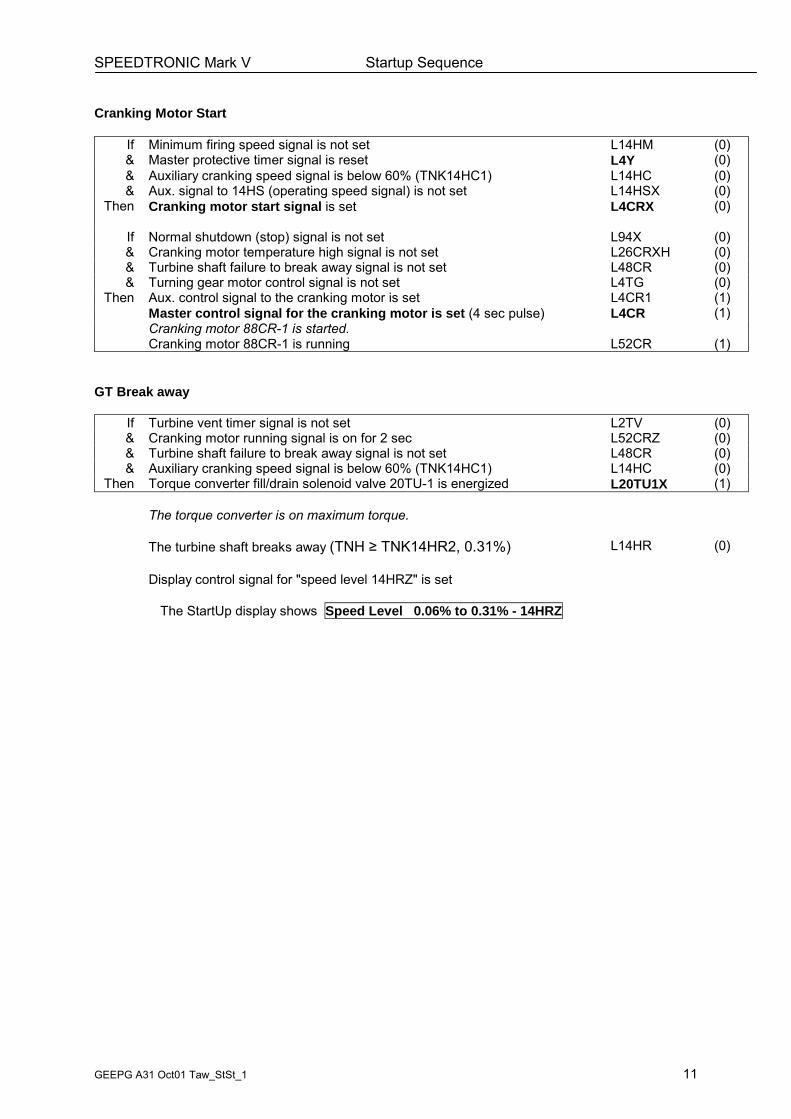
Cranking Motor Start
If Minimum firing speed signal is not set L14HM (0)& Master protective timer signal is reset L4Y (0)& Auxiliary cranking speed signal is below 60% (TNK14HC1) L14HC (0)& Aux. signal to 14HS (operating speed signal) is not set L14HSX (0)
Then Cranking motor start signal is set L4CRX (0)
If Normal shutdown (stop) signal is not set L94X (0)& Cranking motor temperature high signal is not set L26CRXH (0)& Turbine shaft failure to break away signal is not set L48CR (0)& Turning gear motor control signal is not set L4TG (0)
Then Aux. control signal to the cranking motor is set L4CR1 (1)Master control signal for the cranking motor is set (4 sec pulse) L4CR (1)Cranking motor 88CR-1 is started.Cranking motor 88CR-1 is running L52CR (1)
GT Break away
If Turbine vent timer signal is not set L2TV (0)& Cranking motor running signal is on for 2 sec L52CRZ (0)& Turbine shaft failure to break away signal is not set L48CR (0)& Auxiliary cranking speed signal is below 60% (TNK14HC1) L14HC (0)
Then Torque converter fill/drain solenoid valve 20TU-1 is energized L20TU1X (1)
Display control signal for "speed level 14HM" is setThe StartUp display shows Speed Level 9.5% to 10.0% - 14HM
The auxiliary run permission for the oil mist separator fan is set L4QV1X (0)The oil mist separator fan motor 88QV-1 is started L4QVZ1 (0)
Bearing lift oil pump control signal for motor 88QB-1 is reset (log. 1 for off) L4QBZ1 (1)The bearing lift oil pump motor 88QB-1 is stopped L52QB (0)
GT Purge
The torque converter control signal is set L83TM1 (1)The torque converter is set to the turbine purge value TMKGV_1 (50DGA) TMGVCV1The turbine speed TNH is above 10.0% (TNH ≥ TNK14HM1) L14HM (1)The vent timer permissive signal is set L3TVP (1)
The unit is not in Off or Crank mode L43O_C (0)Turbine multiple start and refiring signal is not set L62TT (0)The turbine air purge timer circuit is started (K2TV, 11min.) L2TV
During purge time the turbine speed increases to approx 20%.
If The turbine air purge time is complete (K2TV, 11min.) L2TV (1)Then The master control signal for the torque adjuster drive motor is set L4TM (1)
The control signal for turbine firing torque is set L83TM2 (1)The torque adjuster is set to the turbine firing torque value (15DGA) TMKGV_2The torque converter fill/drain solenoid valve 20TU-1 is deenergized L20TU1X (0)
The turbine speed will drop to the firing value (10 - 12%).
SPEEDTRONIC Mark V Startup Sequence
GEEPG A31 Oct01 Taw_StSt_1 15
Firing
If The turbine speed TNH drops below TNK14TM2 (12%) L14TMF (1)Then The firing speed auxiliary logic signal is set L14TMFZ (1)
The firing permissive signal is set L2TVZ (1)
The torque converter fill/drain solenoid valve 20TU-1 is energized L20TU1X (1)
The ignition permission signal is set L2TVX (1)
The ignition transformers (95SG-11, 12) are energized L2TVX1, 2 (1)The ignition timer is started (K2FGAS is 10sec, K2FLIQ is 30sec) L2F
Display control signal for "Ignition" is set L83SUFI (1)The StartUp display shows Startup Status Firing
Display control signal for "FSR Startup control" is set L30F_SU (1)The StartUp display shows Fuel Control Startup
On Gas fuel:Gas Fuel Stop Valve Open permissive signal is set L3GCV (1)Gas Ratio Valve Open permissive signal is set L3GRV (1)
The reference value FPRGOUT for the SRV is set to the firing value FPRGOUTThe SRV opens and is controlling the pressure FPG2 for firing FPRGV2
FSR is set to the ignition value FSKSU_FI • CQTC L83SUFI (1)The reference value FSROUT for the GCV is set to FSR2 FSROUTThe GCV opens and is controlling the valve position for firing FSROUTV2
The gas splitter valve GSV is in primary position (FSRXSR is 100%) FSRXGSV2
The gas fuel aux. control signal is set (15 sec TD to L3GCV) L20FGZ (1)Control oil pressure switches for gas fuel (63HG-1, -2, -3) are monitored L63HGL_SENSR
On Liquid fuel:The liquid fuel stop valve control signal is set L20FLX (1)The liquid fuel stop solenoid valve signal is set L20FL1X (1)The liquid fuel solenoid valve 20FL-1 is energized (<P>).Liquid fuel pressure is not low L63FL2L (0)Distillate fuel supply pressure low signal is not set L63FLX1 (0)Liquid fuel stop valve (20FL-1, turbine) is in open position L33FL2O (1)Liquid fuel magnetic clutch solenoid is energized L20CF1X (1)
Liquid fuel stop valve (20FL-1, turbine) is not in closed position L33FL1C (0)Fuel flow divider motor (88FM) is started for 5 sec. L4FM (1)
The fuel reference value FQROUT is set to firing value (see note) FQROUTThe LFBV closes dependent on FQROUT FQROUTV2
The liquid fuel aux. control signal is set (15 sec TD to L20FLX) L20FLZ (1)Control oil pressure switches for liquid fuel (63HL-1, -2, -3) are monitored L63HLL_SENSR
Note: FQROUT is set to: FSR1 � TNH/100%. FSR1 = FSKSU_FI� CQTC.
SPEEDTRONIC Mark V Startup Sequence
GEEPG A31 Oct01 Taw_StSt_1 16
Flame Detection
If Prim Flames are detected in two of four comb chambers 1, 2, 3 and 14 L28FDA, B, ... (1)Then Firing is successful (two of four flames are required) L28FD (1)
Display control signals for "Flames" are set L28FDA ... (1)The StartUp GT/Gen schematic display shows two or more flames.
The master flame signal is set L28FDX (1)
Note: Below 14HS speed, flames are allowed to flicker for < 1sec.
The next step in the startup sequence is WARMUPIn case the flame signals are not detected (2 of 4) theunit is in the condition "FAILURE TO IGNITE".See the following chapter.
SPEEDTRONIC Mark V Startup Sequence
GEEPG A31 Oct01 Taw_StSt_1 17
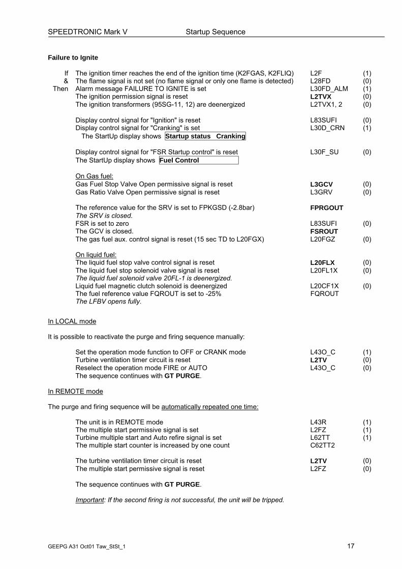
Failure to Ignite
If The ignition timer reaches the end of the ignition time (K2FGAS, K2FLIQ) L2F (1)& The flame signal is not set (no flame signal or only one flame is detected) L28FD (0)
Then Alarm message FAILURE TO IGNITE is set L30FD_ALM (1)The ignition permission signal is reset L2TVX (0)The ignition transformers (95SG-11, 12) are deenergized L2TVX1, 2 (0)
Display control signal for "Ignition" is reset L83SUFI (0)Display control signal for "Cranking" is set L30D_CRN (1)
The StartUp display shows Startup status Cranking
Display control signal for "FSR Startup control" is reset L30F_SU (0)The StartUp display shows Fuel Control
On Gas fuel:Gas Fuel Stop Valve Open permissive signal is reset L3GCV (0)Gas Ratio Valve Open permissive signal is reset L3GRV (0)
The reference value for the SRV is set to FPKGSD (-2.8bar) FPRGOUTThe SRV is closed.FSR is set to zero L83SUFI (0)The GCV is closed. FSROUTThe gas fuel aux. control signal is reset (15 sec TD to L20FGX) L20FGZ (0)
On liquid fuel:The liquid fuel stop valve control signal is reset L20FLX (0)The liquid fuel stop solenoid valve signal is reset L20FL1X (0)The liquid fuel solenoid valve 20FL-1 is deenergized.Liquid fuel magnetic clutch solenoid is deenergized L20CF1X (0)The fuel reference value FQROUT is set to -25% FQROUTThe LFBV opens fully.
In LOCAL mode
It is possible to reactivate the purge and firing sequence manually:
Set the operation mode function to OFF or CRANK mode L43O_C (1)Turbine ventilation timer circuit is reset L2TV (0)Reselect the operation mode FIRE or AUTO L43O_C (0)The sequence continues with GT PURGE.
In REMOTE mode
The purge and firing sequence will be automatically repeated one time:
The unit is in REMOTE mode L43R (1)The multiple start permissive signal is set L2FZ (1)Turbine multiple start and Auto refire signal is set L62TT (1)The multiple start counter is increased by one count C62TT2
The turbine ventilation timer circuit is reset L2TV (0)The multiple start permissive signal is reset L2FZ (0)
The sequence continues with GT PURGE.
Important: If the second firing is not successful, the unit will be tripped.
SPEEDTRONIC Mark V Startup Sequence
GEEPG A31 Oct01 Taw_StSt_1 18
Warmup
The master flame signal is detected L28FDX (1)
Display control signal for "Warmup" is set L83SUWU (1)The StartUp display shows Startup Status Warmup
The warmup timer circuit is started (K2W, 60sec) L2W
The fired hours timer is started L30FT_T (1)
The flame detector timer is set with 2 sec time delay to L28FDX L2WZ (1)The master control torque adjuster signal is reset L4TM (0)
The control signal for maximum converter torque is set L83TM4 (1)The torque adjuster is set to maximum converter torque (68DGA) TMKGV_4The torque converter fill/drain solenoid valve 20TU-1 is already energized.
The ignition timer circuit (K2FGAS, K2FLIQ) is complete L2F (1)The ignition transformer (95SG-11, 12) are deenergized L2TVX1, 2 (0)The fired starts counter is incremented L30CFS (1)
Exhaust frame cooling fansTurbine exhaust frame cooling fan motor 88TK-1 is started L4TKZ1 (0)Exhaust frame cooling fan motor 88TK-2 is started with 10sec time delay L4TKZ2 (0)
Load Compartment VentilationThe load compartment ventilation is enabled with flame signal L4VGZ1 (0)The load compartment fan motor 88VG-1 is started.
Acceleration
The warmup timer circuit (K2W, 60sec) is complete L2W (1)Startup FSR accelerate fuel command is enabled L83SUAR (1)FSRSU is increasing with a rate of FSKSU_IA (0.05%/sec) FSRSUV1
Display control signal for "FSR Startup control" is still on L30F_SU (1)The StartUp display shows Fuel Control Startup
Display control signal for "accelerating" is set L30D_ACN (1)The StartUp display shows Startup Status Accelerating
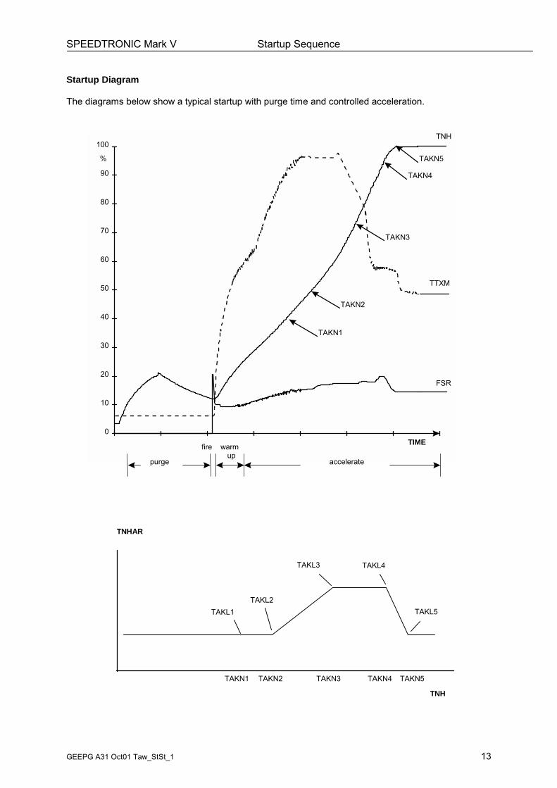
Acceleration control is on when the turbine reaches anacceleration value TNHA of 0.11%/sec (TAKL1).
Fuel stroke reference FSR is controlled by the accel. controller FSRACCV1
Display control signal for "FSR acceleration control" is set L30F_ACN (1)The StartUp display shows Fuel Control Acceleration-HP
The turbine is accelerated with the acceleration rate TNHAR,which is varying with the turbine speed TNH.The initial acceleration value is 0.11 %/sec (TAKL1), the maximumacceleration value is 0.31%/sec (TAKL3, TAKL4).
Display control signal for "speed level 14HS" is setThe StartUp display shows Speed Level 94% to 95% - 14HS
The Auxiliary lube oil pump motor 88QA-1 is switched off L4QAZ (1)The Auxiliary hydraulic oil pump motor 88HQ-1 is switched off L4HQZ (1)
Field FlashingHP speed is at field flashing speed setpoint, 95% (TNH ≥ TNK14HF1) L14HF (1)Field flashing is enabled for 5sec (K2GFF1) L41FX (1)
Combustion monitor function is enabled (14HS + 60s) L83SPM
SPEEDTRONIC Mark V Startup Sequence
GEEPG A31 Oct01 Taw_StSt_1 20
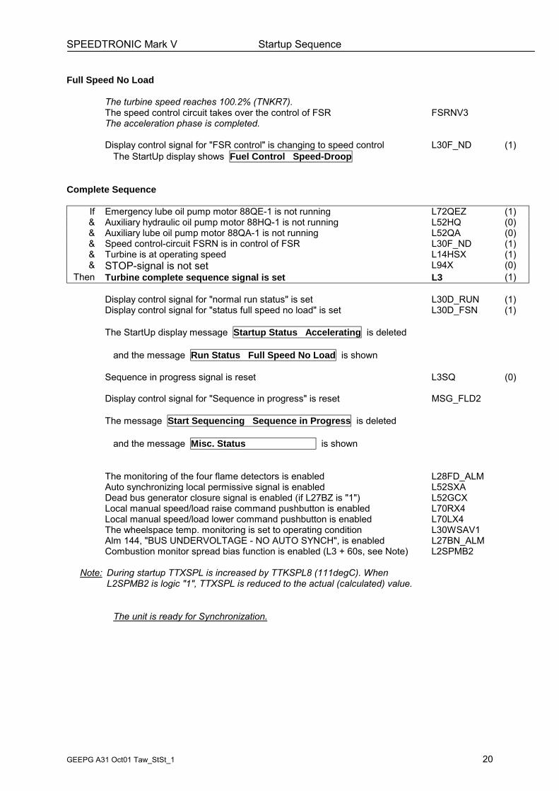
Full Speed No Load
The turbine speed reaches 100.2% (TNKR7).The speed control circuit takes over the control of FSR FSRNV3The acceleration phase is completed.
Display control signal for "FSR control" is changing to speed control L30F_ND (1)The StartUp display shows Fuel Control Speed-Droop
Complete Sequence
If Emergency lube oil pump motor 88QE-1 is not running L72QEZ (1)& Auxiliary hydraulic oil pump motor 88HQ-1 is not running L52HQ (0)& Auxiliary lube oil pump motor 88QA-1 is not running L52QA (0)& Speed control-circuit FSRN is in control of FSR L30F_ND (1)& Turbine is at operating speed L14HSX (1)& STOP-signal is not set L94X (0)
Then Turbine complete sequence signal is set L3 (1)
Display control signal for "normal run status" is set L30D_RUN (1)Display control signal for "status full speed no load" is set L30D_FSN (1)
The StartUp display message Startup Status Accelerating is deleted
and the message Run Status Full Speed No Load is shown
Sequence in progress signal is reset L3SQ (0)
Display control signal for "Sequence in progress" is reset MSG_FLD2
The message Start Sequencing Sequence in Progress is deleted
and the message Misc. Status is shown
The monitoring of the four flame detectors is enabled L28FD_ALMAuto synchronizing local permissive signal is enabled L52SXADead bus generator closure signal is enabled (if L27BZ is "1") L52GCXLocal manual speed/load raise command pushbutton is enabled L70RX4Local manual speed/load lower command pushbutton is enabled L70LX4The wheelspace temp. monitoring is set to operating condition L30WSAV1Alm 144, "BUS UNDERVOLTAGE - NO AUTO SYNCH", is enabled L27BN_ALMCombustion monitor spread bias function is enabled (L3 + 60s, see Note) L2SPMB2
Note: During startup TTXSPL is increased by TTKSPL8 (111degC). WhenL2SPMB2 is logic "1", TTXSPL is reduced to the actual (calculated) value.
The unit is ready for Synchronization.
SPEEDTRONIC Mark V Startup Sequence
GEEPG A31 Oct01 Taw_StSt_1 21
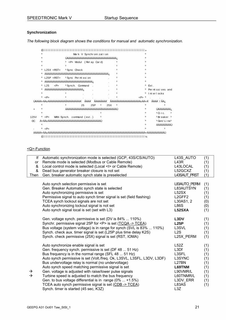
Synchronization
The following block diagram shows the conditions for manual and automatic synchronization.
If Automatic synchronization mode is selected (GCP, 43S/CS/AUTO) L43S_AUTO (1)or Remote mode is selected (Modbus or Cable Remote) L43R (1)& Local control mode is selected (Local <I> or Cable Remote) L43LOCAL (1)& Dead bus generator breaker closure is not set L52GCXZ (1)
Then Gen. breaker automatic synch state is preselected L43SAUT_PRST (1)
Auto synch selection permissive is set L83AUTO_PERM (1)Gen. Breaker Automatic synch state is selected L83AUTSYN (1)Auto synchronizing permissive is set L52SX (1)Permissive signal to auto synch timer signal is set (field flashing) L2GFF2 (1)TCEA synch lockout signals are not set L30AS1, 2 (0)Auto synchronizing lockout signal is not set L86S (0)Auto synch signal local is set (set with L3) L52SXA (1)
Gen. voltage synch. permissive is set (DV is 84% ... 110%) L3DV (1)Synchr. permissive signal 25P for <P> is set (TCQA -> TCEA) L25P (1)Bus voltage (system voltage) is in range for synch (SVL is 83% ... 110%) L3SVL (1)Synch. check aux. timer signal is set (L25P plus time delay K2S) L2S (1)Synch. check permissive (25X) signal is set (RST, IOMA) L25X_PERM (1)
Auto synchronize enable signal is set L52Z (1)Gen. frequency synch. permissive is set (DF 48 ... 51 Hz) L3Df (1)Bus frequency is in the normal range (SFL 48 ... 51 Hz) L3SFL (1)Auto synch permissive is set (Volt./freq. Ok, L3SVL, L3SFL, L3DV, L3DF) L3SYNC (1)Bus undervoltage relay is normal (no undervoltage) L27BN (1)Auto synch speed matching permissive signal is set L69TNM (1)
! Gen. voltage is adjusted with raise/lower pulse signals L90VMR/L (1)! Turbine speed is adjusted to match the bus frequency L60TNMR/L (1)
Gen. to bus voltage differential is in range (0% ... +1.5%) L3DV_ERR (1)TCEA auto synch permissive signal is set (CDB -> TCEA) L83AS (1)Synch. timer is started (45 sec, K3Z) L3Z
SPEEDTRONIC Mark V Startup Sequence
GEEPG A31 Oct01 Taw_StSt_1 22
Synchronization (cont´d)
Display control signal for "Synchronizing" is set L30D_SYN (1)The StartUp display shows Run Status Synchronizing
<Q> IOMA Settings:Phase differential limit is set to < ±10 degrees.Frequency diff limit is set to < ±0.3Hz.IOMA Synch check relay status signal is set (RST to P, internal) L25X
<P>-Function1. Phase- and frequency-difference have to match
the synchronization-window (<0.3Hz, <10 degrees).2. Before the closing command for the Gen. CB is given, the
The Generator has to be overexcited for 10 successive cycles.3. The "on"-command for the Gen. CB will be set for
at least 12 cycles.
The main synchronizing signal "25" in <P> is set L25 (1)
The Generator circuit breaker is closed L52GX (1)
Display control signal for "Start" is reset (30 sec after 52G is closed) L30D_STR (0)The StartUp display message Turbine State is shown
SPEEDTRONIC Mark V Startup Sequence
GEEPG A31 Oct01 Taw_StSt_1 23
Spinning Reserve
After closing of the Gen. circuit breaker the turbine speed is 100%.If no load mode is selected the unit is loaded automatically toSpinning Reserve.
The Generator circuit breaker is closed L52GX (1)Compressor bleed valve control signal is set L20CBX (1)Compressor bleed valve solenoid 20CB-1 is energized L20CB1X (1)The bleed valves are closed.
Atomizing air booster solenoid 20AB-1 is energized L20AB1X (1)
The Generator load is measured with 3 transmitters DWATT MWDWDROOP (load value in %) is calculated with DWATT DWDROOP %The speed reference value TNR is the load reference value TNRV1 %Reference value for the speed-/load control-circuit is TNRL TNRLV3 %FSR is controlled by the speed-/load control FSRN FSRNV3 %
The load control circuit compares DWATT with thespinning reserve value LK90SPIN (typ. 5.0MW) L90LV2
The load control circuit sets the RAISE signal for TNR L90LR (1)The aux. raise signal for setpoint TNR is set L70RX5 (1)The master raise signal for setpoint TNR is set L70R (1)Setpoint TNR is increasing from 100.0% to approx. 100.4% TNRV1 %TNR is increasing with the "AUTO load rate" (typ. 0.33%/min.) TNKR1_4
Note: The load rate is to be seen as "%TNR/min."
Display control signal for "Loading" is set L30D_LD (1)The StartUp display shows Run Status Loading
For all load conditions below base load, FSR is alwayscontrolled by the speed-/load control-circuit FSRN FSRNV3
Display control signal for "FSR control" is still indicated L30F_ND (1)The StartUp display shows Fuel Control Speed-Droop
The Generator load DWATT reaches the minimum load value LK90SPIN.
The aux. raise signal for setpoint TNR is reset L70RX5 (0)The master raise signal for setpoint TNR is reset L70R (0)
The loading is stopped.
Display control signal for "Spinning Reserve" is set L30D_SPN (1)The StartUp display shows Run Status Spinning Reserve
The value for Spinning Reserve can be adjusted viaconstant LK90SPIN (Display Control Constants Adjust).
SPEEDTRONIC Mark V Startup Sequence
GEEPG A31 Oct01 Taw_StSt_1 24
Manual Loading
If A manual raise command is given from the Mark V <I> or from DCS,from the Generator Control Panel (GCP) or from cable remote L70RX4 (1)
Then The master raise signal for setpoint TNR is set L70R (1)
The load control is set to manual mode L83AM (1)TNR is increasing with the "manual load rate" (typ. 0.66%/min.) TNKR1_2
Display control signal for "Loading" is set L30D_LD (1)The StartUp display shows Run Status Loading
When the load adjustment is done:The master raise signal for setpoint TNR is reset L70R (0)
Display control signal for "Part Load" is set L30D_PLD (1)The StartUp display shows Run Status Part Load
Preselected Load
Important:Before activating the load mode "Preselected Load"the actual setting of the load setpoint must be checkedand -if required- adjusted.
Load mode "Preselected Load" is set from <I> or from DCS SC43LOAD
Display control signal for "Preselected Load" is set L83PS (1)The StartUp display shows Turbine State Preselect
The load control is set to automatic L83AM (0)The load control circuit compares DWATT with thepreselected load setpoint value L90PSEL L90LV2The load control circuit sets the RAISE signal for TNR L90LR (1)The aux. raise signal for TNR is set L70RX5 (1)The master raise signal for setpoint TNR is set L70R (1)TNR is increasing with the "AUTO load rate" (typ. 0.33%/min.) TNKR1_4
Display control signal for "Loading" is set L30D_LD (1)The StartUp display shows Run Status Loading
When the adjusted load setpoint value is reached (± LK90DB1, ±0.25MW)the RAISE command is reset.
The aux. raise signal for TNR is reset L70RX5 (0)The master raise signal for setpoint TNR is reset L70R (0)
Display control signal for "Preselect Load" is set L30D_PS (1)The StartUp display shows Run Status Preselect Load
Note: If DWATT deviates from the adjusted load setpoint valuefor > LK90DB2 (2.0MW), RAISE/LOWER signals are setto adjust DWATT to the setpoint value (± LK90DB1, ±0.25MW).
SPEEDTRONIC Mark V Startup Sequence
GEEPG A31 Oct01 Taw_StSt_1 25
IGV Control
Two modes of operation are possible.
Control mode "IGV TEMPERATURE CONTROL OFF" is selected L83TVON_CMD (0)
The IGV are opening during loading from 57° to 84°, when theexhaust temperature has reached 371°C (approx. at 35% load).This control mode is called Simple Cycle (SC) mode.
Control mode "IGV TEMPERATURE CONTROL ON" is selected L83TVON_CMD (1)
The IGV are kept at 57° during loading until the exhaust temperatureTTXM has reached the exhaust temperature limit value TTRXB.When the loading continues, the IGV are opening up to full openposition. At Base load the IGV are fully open to 84°.This control mode is called Combined Cycle (CC) mode.
Important:For all DLN operation modes the IGV temperature control mode shouldalways be set to IGV Temp Control mode "ON".
SPEEDTRONIC Mark V Startup Sequence
GEEPG A31 Oct01 Taw_StSt_1 26
Base Load
Load mode "Base Load" is set from <I> or from DCS SC43LOAD
Display control signal for "Base Load" is set L83B (1)The StartUp display shows Turbine State Base Select
The load control is set to automatic L83AM (0)The signal for MAX load for the AUTO REGULATOR is set L83RMAX (1)
The load control circuit compares DWATT with themaximum load setpoint value LK90MAX L90LV2
The load control circuit sets the RAISE signal for TNR L90LR (1)The aux. raise signal for TNR is set L70RX5 (1)The master raise signal for setpoint TNR is set L70R (1)TNR is increasing with the "AUTO load rate" (typ. 0.33%/min.) TNKR1_4
Display control signal for "Loading" is set L30D_LD (1)The StartUp display shows Run Status Loading
When the exhaust temp. reaches the base load value TTRXB,the Exhaust Temperature Control circuit FSRT is limiting FSR. L70R (0)
FSR is controlled by the Temperature Control circuit FSRT FSRTV3
Display control signal for "Base Load" is set L30D_B (1)The StartUp display shows Run Status Base Load
The load Raise command is reset, when FSRN > FSRT + 3% INHIBIT RAISE (1)The master raise signal for setpoint TNR is reset L70R (0)
The maximum load depends on the compressor inlet temperature CTIM.
The Unit is at Base Load.
SPEEDTRONIC Mark V Startup Sequence
GEEPG A31 Oct01 Taw_StSt_1 27
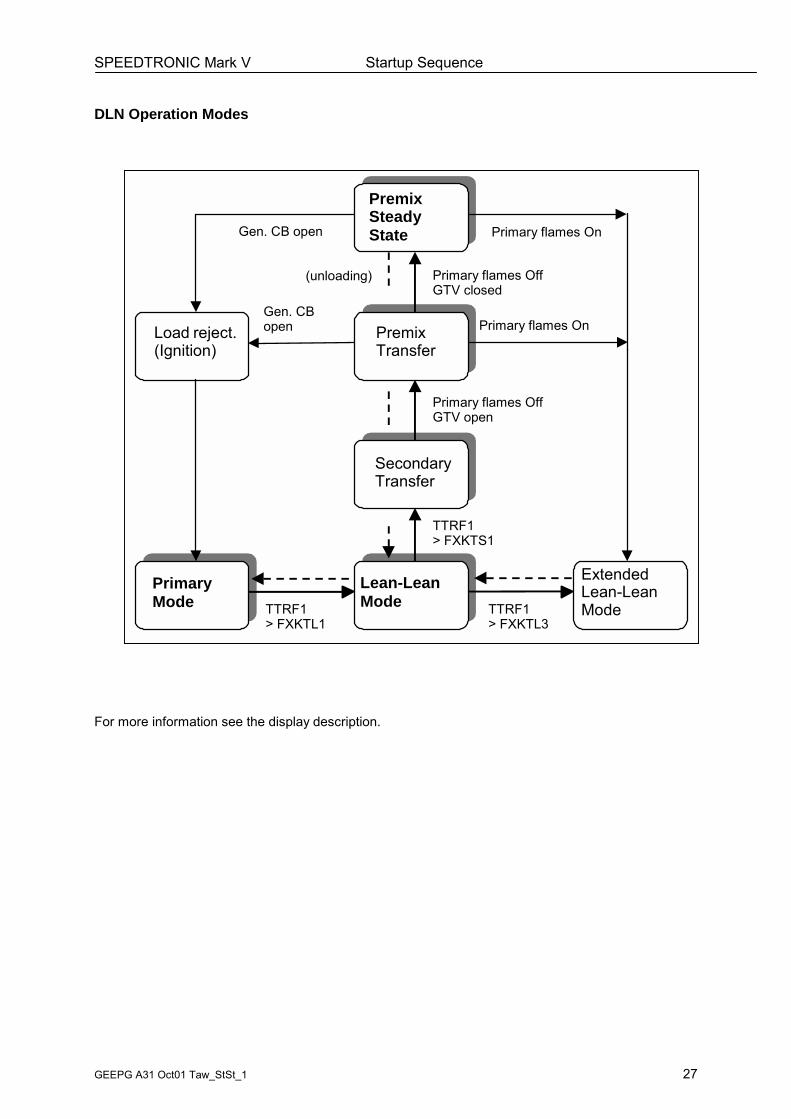
DLN Operation Modes
For more information see the display description.
Primär-Betrieb
Lean-LeanMode
SecondaryTransfer
TTRF1> FXKTS1
TTRF1> FXKTL1
Primary flames OffGTV open
PremixTransfer
PremixSteadyState
Primary flames OffGTV closed
Primary flames OnGen. CB open
Gen. CBopenLoad reject.
(Ignition)Primary flames On
ExtendedLean-LeanModeTTRF1
> FXKTL3
PrimaryMode
(unloading)
SPEEDTRONIC Mark V Startup Sequence
GEEPG A31 Oct01 Taw_StSt_1 28
Notes:
SPEEDTRONIC Mark V Stop Sequence
GEEPG A31 Oct01 Taw_StSt_1 29
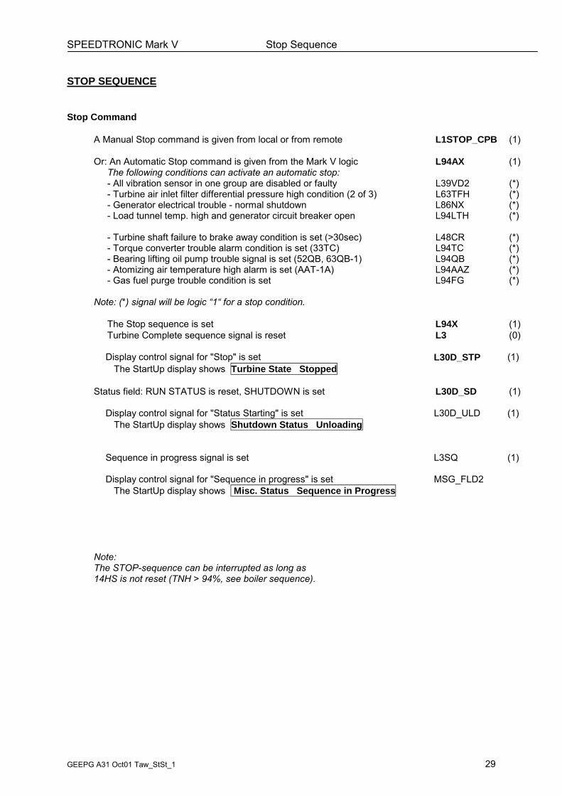
STOP SEQUENCE
Stop Command
A Manual Stop command is given from local or from remote L1STOP_CPB (1)
Or: An Automatic Stop command is given from the Mark V logic L94AX (1)The following conditions can activate an automatic stop:- All vibration sensor in one group are disabled or faulty L39VD2 (*)- Turbine air inlet filter differential pressure high condition (2 of 3) L63TFH (*)- Generator electrical trouble - normal shutdown L86NX (*)- Load tunnel temp. high and generator circuit breaker open L94LTH (*)
- Turbine shaft failure to brake away condition is set (>30sec) L48CR (*)- Torque converter trouble alarm condition is set (33TC) L94TC (*)- Bearing lifting oil pump trouble signal is set (52QB, 63QB-1) L94QB (*)- Atomizing air temperature high alarm is set (AAT-1A) L94AAZ (*)- Gas fuel purge trouble condition is set L94FG (*)
Note: (*) signal will be logic �1� for a stop condition.
The Stop sequence is set L94X (1)Turbine Complete sequence signal is reset L3 (0)
Display control signal for "Stop" is set L30D_STP (1)The StartUp display shows Turbine State Stopped
Status field: RUN STATUS is reset, SHUTDOWN is set L30D_SD (1)
Display control signal for "Status Starting" is set L30D_ULD (1)The StartUp display shows Shutdown Status Unloading
Sequence in progress signal is set L3SQ (1)
Display control signal for "Sequence in progress" is set MSG_FLD2The StartUp display shows Misc. Status Sequence in Progress
Note:The STOP-sequence can be interrupted as long as14HS is not reset (TNH > 94%, see boiler sequence).
SPEEDTRONIC Mark V Stop Sequence
GEEPG A31 Oct01 Taw_StSt_1 30
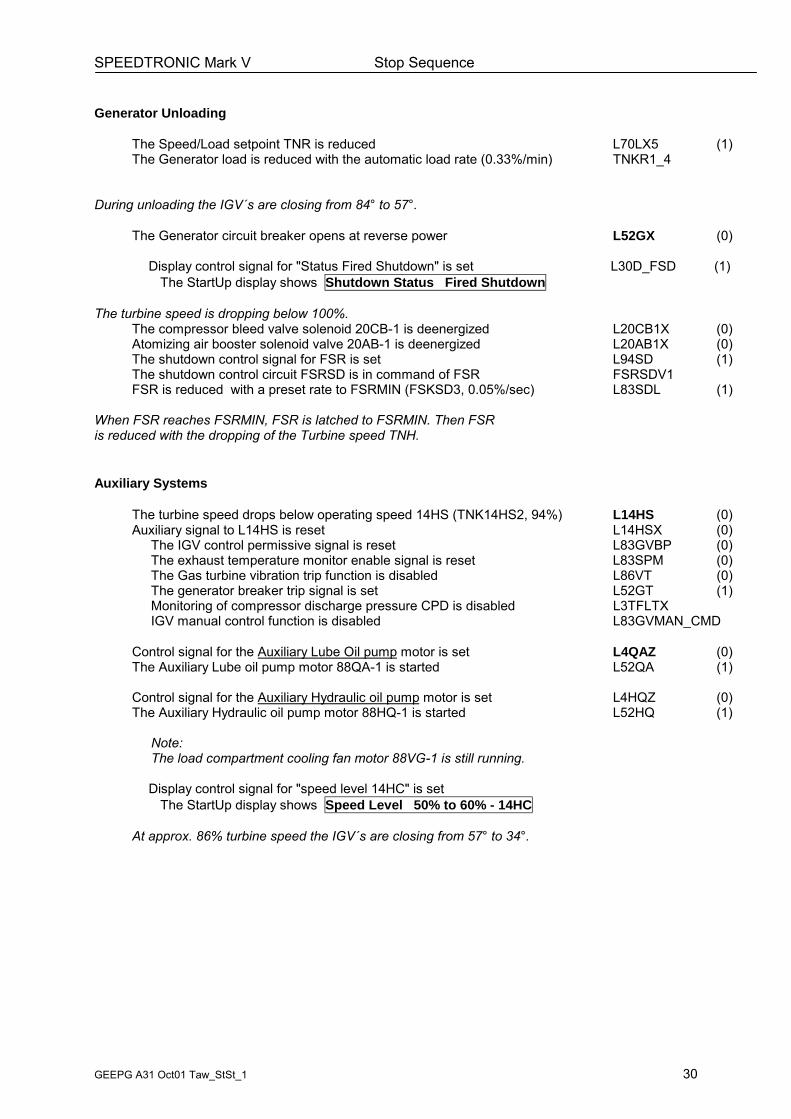
Generator Unloading
The Speed/Load setpoint TNR is reduced L70LX5 (1)The Generator load is reduced with the automatic load rate (0.33%/min) TNKR1_4
During unloading the IGV´s are closing from 84° to 57°.
The Generator circuit breaker opens at reverse power L52GX (0)
Display control signal for "Status Fired Shutdown" is set L30D_FSD (1)The StartUp display shows Shutdown Status Fired Shutdown
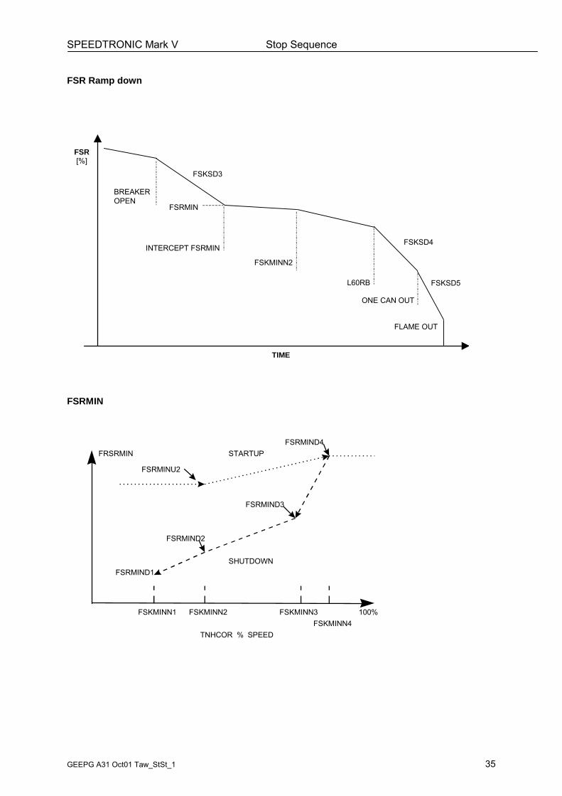
The turbine speed is dropping below 100%.The compressor bleed valve solenoid 20CB-1 is deenergized L20CB1X (0)Atomizing air booster solenoid valve 20AB-1 is deenergized L20AB1X (0)The shutdown control signal for FSR is set L94SD (1)The shutdown control circuit FSRSD is in command of FSR FSRSDV1FSR is reduced with a preset rate to FSRMIN (FSKSD3, 0.05%/sec) L83SDL (1)
When FSR reaches FSRMIN, FSR is latched to FSRMIN. Then FSRis reduced with the dropping of the Turbine speed TNH.
Auxiliary Systems
The turbine speed drops below operating speed 14HS (TNK14HS2, 94%) L14HS (0)Auxiliary signal to L14HS is reset L14HSX (0)
The IGV control permissive signal is reset L83GVBP (0)The exhaust temperature monitor enable signal is reset L83SPM (0)The Gas turbine vibration trip function is disabled L86VT (0)The generator breaker trip signal is set L52GT (1)Monitoring of compressor discharge pressure CPD is disabled L3TFLTXIGV manual control function is disabled L83GVMAN_CMD
Control signal for the Auxiliary Lube Oil pump motor is set L4QAZ (0)The Auxiliary Lube oil pump motor 88QA-1 is started L52QA (1)
Control signal for the Auxiliary Hydraulic oil pump motor is set L4HQZ (0)The Auxiliary Hydraulic oil pump motor 88HQ-1 is started L52HQ (1)
Note:The load compartment cooling fan motor 88VG-1 is still running.
Display control signal for "speed level 14HC" is setThe StartUp display shows Speed Level 50% to 60% - 14HC
At approx. 86% turbine speed the IGV´s are closing from 57° to 34°.
SPEEDTRONIC Mark V Stop Sequence
GEEPG A31 Oct01 Taw_StSt_1 31
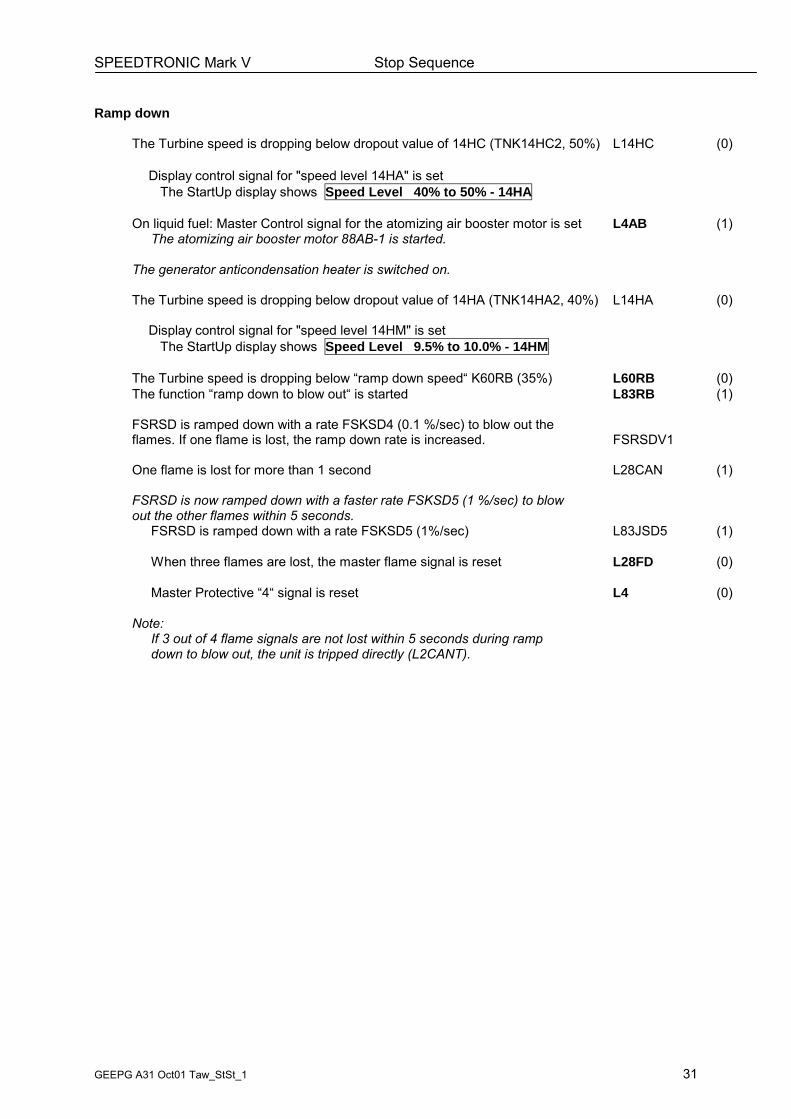
Ramp down
The Turbine speed is dropping below dropout value of 14HC (TNK14HC2, 50%) L14HC (0)
Display control signal for "speed level 14HA" is setThe StartUp display shows Speed Level 40% to 50% - 14HA
On liquid fuel: Master Control signal for the atomizing air booster motor is set L4AB (1)The atomizing air booster motor 88AB-1 is started.
The generator anticondensation heater is switched on.
The Turbine speed is dropping below dropout value of 14HA (TNK14HA2, 40%) L14HA (0)
Display control signal for "speed level 14HM" is setThe StartUp display shows Speed Level 9.5% to 10.0% - 14HM
The Turbine speed is dropping below �ramp down speed� K60RB (35%) L60RB (0)The function �ramp down to blow out� is started L83RB (1)
FSRSD is ramped down with a rate FSKSD4 (0.1 %/sec) to blow out theflames. If one flame is lost, the ramp down rate is increased. FSRSDV1
One flame is lost for more than 1 second L28CAN (1)
FSRSD is now ramped down with a faster rate FSKSD5 (1 %/sec) to blowout the other flames within 5 seconds.
FSRSD is ramped down with a rate FSKSD5 (1%/sec) L83JSD5 (1)
When three flames are lost, the master flame signal is reset L28FD (0)
Master Protective �4� signal is reset L4 (0)
Note:If 3 out of 4 flame signals are not lost within 5 seconds during rampdown to blow out, the unit is tripped directly (L2CANT).
SPEEDTRONIC Mark V Stop Sequence
GEEPG A31 Oct01 Taw_StSt_1 32
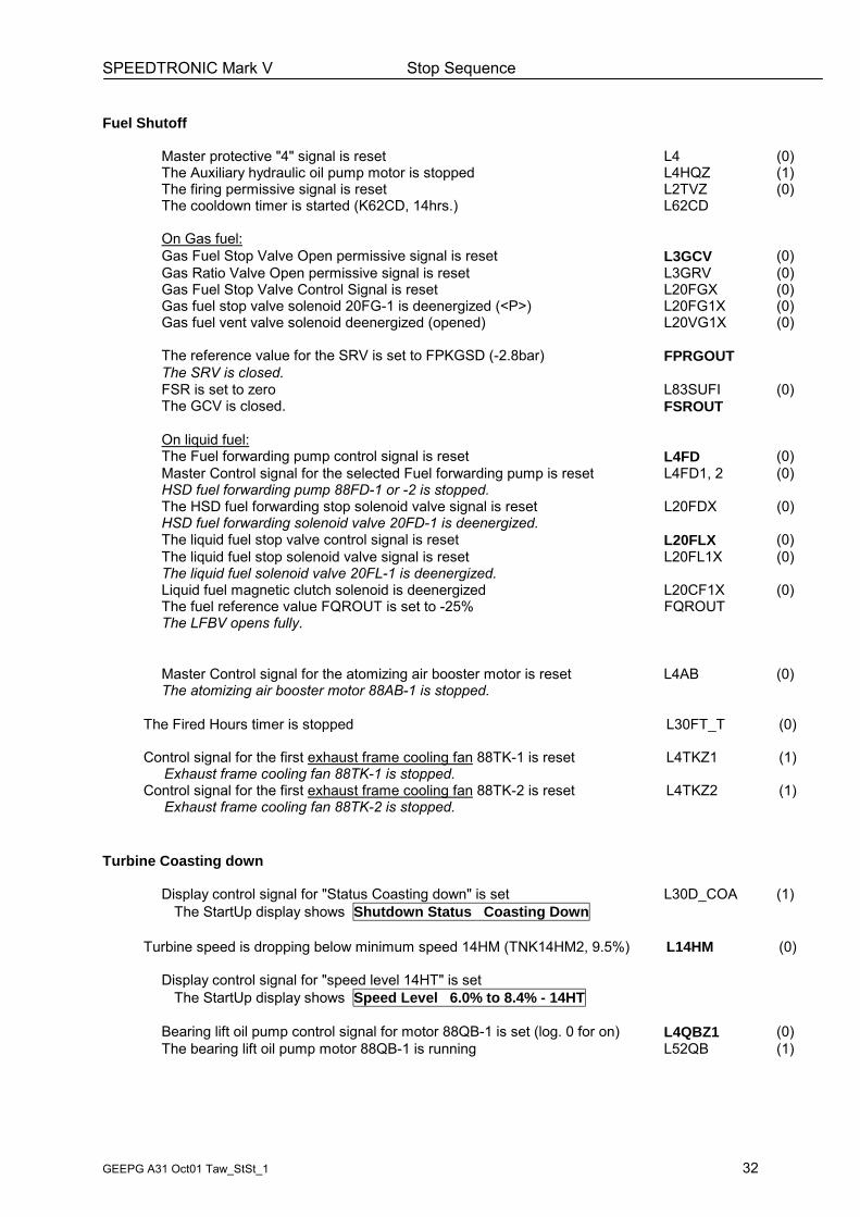
Fuel Shutoff
Master protective "4" signal is reset L4 (0)The Auxiliary hydraulic oil pump motor is stopped L4HQZ (1)The firing permissive signal is reset L2TVZ (0)The cooldown timer is started (K62CD, 14hrs.) L62CD
On Gas fuel:Gas Fuel Stop Valve Open permissive signal is reset L3GCV (0)Gas Ratio Valve Open permissive signal is reset L3GRV (0)Gas Fuel Stop Valve Control Signal is reset L20FGX (0)Gas fuel stop valve solenoid 20FG-1 is deenergized (<P>) L20FG1X (0)Gas fuel vent valve solenoid deenergized (opened) L20VG1X (0)
The reference value for the SRV is set to FPKGSD (-2.8bar) FPRGOUTThe SRV is closed.FSR is set to zero L83SUFI (0)The GCV is closed. FSROUT
On liquid fuel:The Fuel forwarding pump control signal is reset L4FD (0)Master Control signal for the selected Fuel forwarding pump is reset L4FD1, 2 (0)HSD fuel forwarding pump 88FD-1 or -2 is stopped.The HSD fuel forwarding stop solenoid valve signal is reset L20FDX (0)HSD fuel forwarding solenoid valve 20FD-1 is deenergized.The liquid fuel stop valve control signal is reset L20FLX (0)The liquid fuel stop solenoid valve signal is reset L20FL1X (0)The liquid fuel solenoid valve 20FL-1 is deenergized.Liquid fuel magnetic clutch solenoid is deenergized L20CF1X (0)The fuel reference value FQROUT is set to -25% FQROUTThe LFBV opens fully.
Master Control signal for the atomizing air booster motor is reset L4AB (0)The atomizing air booster motor 88AB-1 is stopped.
The Fired Hours timer is stopped L30FT_T (0)
Control signal for the first exhaust frame cooling fan 88TK-1 is reset L4TKZ1 (1)Exhaust frame cooling fan 88TK-1 is stopped.
Control signal for the first exhaust frame cooling fan 88TK-2 is reset L4TKZ2 (1)Exhaust frame cooling fan 88TK-2 is stopped.
Turbine Coasting down
Display control signal for "Status Coasting down" is set L30D_COA (1)The StartUp display shows Shutdown Status Coasting Down
Display control signal for "speed level 14HT" is setThe StartUp display shows Speed Level 6.0% to 8.4% - 14HT
Bearing lift oil pump control signal for motor 88QB-1 is set (log. 0 for on) L4QBZ1 (0)The bearing lift oil pump motor 88QB-1 is running L52QB (1)
SPEEDTRONIC Mark V Stop Sequence
GEEPG A31 Oct01 Taw_StSt_1 33
Turbine Cooldown
The turbine speed drops below 6.0% (TNK14HT2) L14HT (0)
Display control signal for "speed level 14HP" is setThe StartUp display shows Speed Level 3.3% to 4.0% - 14HP
Display control signal for "Status On cooldown" is set L30D_CD (1)The StartUp display shows Shutdown Status On Cooldown
The turbine speed drops below 3.3% (TNK14HP2) L14HP (0)
Display control signal for "speed level 14HRZ" is setThe StartUp display shows Speed Level 0.06% to 0.31% - 14HRZ
Turning gear motor 88TG-1 is started L4TG1X (1)Torque converter solenoid valve 20TU-1 is energized L20TU1X (1)
The turbine speed drops to approx. 120rpm.The turbine rotor is turned by the turning gear motor.
The unit is on cooldown.
Emergency Cooldown
If there is an AC failure during cooldown, all AC motors are stoppedimmediately. The turbine speed drops to zero.The normal cooldown sequence is interrupted and the followingemergency cooldown sequence begins.
The emergency lube oil pump starts when lube oil pressure lowis monitored. At zero speed of the turbine the On/Off timer for theemergency cooldown cycle are enabled:The emergency lube oil pump is on for 3 minutes (K4QEON)and off for 15 minutes (K4QEOFF).
When AC voltage is reastablished, the Auxiliary lube oil pump motorand the Bearing lift oil pump motor is restarted.The cooldown continues without turning of the turbine shaft.
SPEEDTRONIC Mark V Stop Sequence
GEEPG A31 Oct01 Taw_StSt_1 34
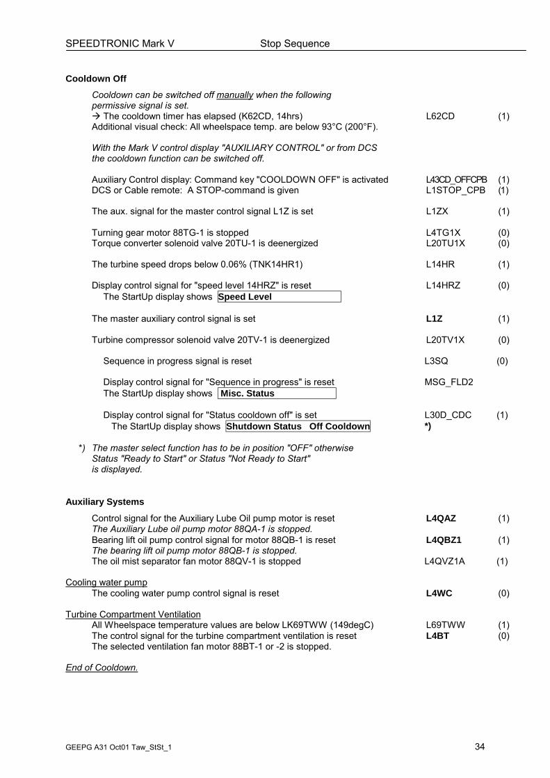
Cooldown OffCooldown can be switched off manually when the followingpermissive signal is set.! The cooldown timer has elapsed (K62CD, 14hrs) L62CD (1)Additional visual check: All wheelspace temp. are below 93°C (200°F).
With the Mark V control display "AUXILIARY CONTROL" or from DCSthe cooldown function can be switched off.
Auxiliary Control display: Command key "COOLDOWN OFF" is activated L43CD_OFFCPB (1)DCS or Cable remote: A STOP-command is given L1STOP_CPB (1)
The aux. signal for the master control signal L1Z is set L1ZX (1)
Turning gear motor 88TG-1 is stopped L4TG1X (0)Torque converter solenoid valve 20TU-1 is deenergized L20TU1X (0)
The turbine speed drops below 0.06% (TNK14HR1) L14HR (1)
Display control signal for "speed level 14HRZ" is reset L14HRZ (0)The StartUp display shows Speed Level
The master auxiliary control signal is set L1Z (1)
Turbine compressor solenoid valve 20TV-1 is deenergized L20TV1X (0)
Sequence in progress signal is reset L3SQ (0)
Display control signal for "Sequence in progress" is reset MSG_FLD2The StartUp display shows Misc. Status
Display control signal for "Status cooldown off" is set L30D_CDC (1)The StartUp display shows Shutdown Status Off Cooldown *)
*) The master select function has to be in position "OFF" otherwiseStatus "Ready to Start" or Status "Not Ready to Start"is displayed.
Auxiliary Systems
Control signal for the Auxiliary Lube Oil pump motor is reset L4QAZ (1)The Auxiliary Lube oil pump motor 88QA-1 is stopped.Bearing lift oil pump control signal for motor 88QB-1 is reset L4QBZ1 (1)The bearing lift oil pump motor 88QB-1 is stopped.The oil mist separator fan motor 88QV-1 is stopped L4QVZ1A (1)
Cooling water pumpThe cooling water pump control signal is reset L4WC (0)
Turbine Compartment VentilationAll Wheelspace temperature values are below LK69TWW (149degC) L69TWW (1)The control signal for the turbine compartment ventilation is reset L4BT (0)The selected ventilation fan motor 88BT-1 or -2 is stopped.