20
STASS “Standard Architecture for Soldier Systems” 15.CAT.OP.071 - STASS Public Executive Summary - Identification: BL 8387 T249 REP Date: 10 Nov. 2016 Revision: 1.03

STASS
“Standard Architecture for Soldier Systems”
15.CAT.OP.071
- STASS Public Executive Summary -
Identification: BL 8387 T249 REP
Date: 10 Nov. 2016
Revision: 1.03
STASS Public Executive Summary
ID: BL 8387 T249 REP Rheinmetall Defence Electronics
DNV GL, Fhg ICT, Larimart
Date: 10 Nov. 2016
Revision: 1.03 Use or disclosure of data contained on this sheet is subject
to restriction on the title page of this document Page 2 of 20
Overview 1
1.1 Architecture Scope
The proposed architecture in this document describes a Reference Power Architecture for Soldier Systems which should be used to derive the target power architecture for a specific system to be procured or built. It may be considered to be standardized or may be used as contribution for standardisation, e.g. by NATO.
As power and data cannot be easily separated, it is however, recommended to finish a complete Soldier System Reference Architecture also covering electronics and data before standardisation.
It is expected that STASS would be standardized and first STASS compliant systems will appear between 2020 and 2025.
1.2 Identification
The proposed architecture was developed between Nov. 2015 and August 2016 under the contract of EDA as study “Standard Architecture for Soldier Systems” (STASS, 15.CAT.OP.071) which explicitly asked for scoping on the power aspects.
The architecture was developed by the integrated project team:
RDE, Rheinmetall Defence Electronics (DEU, prime contractor),
o Dr. Norbert Härle (Contract Manager),
o Mario Sonka
DNV GL (Trade name for KEMA Nederland B.V., NLD)
o Jasper Groenewegen
o Dr. Rianne ´t Hoen
FhG ICT, Fraunhofer-Gesellschaft Institut für Chemische Technologie (DEU),
o Dr. Carsten Cremers
o Dr. Sophie Weixler
Larimart (ITA)
o Fabrizio Parmeggiani
o Dr. Matteo Sedehi
1.3 Background
Since several years Open Architectures or Generic Architectures are seen as a key to make complex systems affordable by
reducing integration effort through standardisation
enhancing competition for sub-systems by making them interchangeable
reducing technical risks by using sub-systems and integration approaches with high Technology Readiness Levels (TRL)
STASS Public Executive Summary
ID: BL 8387 T249 REP Rheinmetall Defence Electronics
DNV GL, Fhg ICT, Larimart
Date: 10 Nov. 2016
Revision: 1.03 Use or disclosure of data contained on this sheet is subject
to restriction on the title page of this document Page 3 of 20
reducing logistic and maintenance efforts by lowering the variety of sub-system and by using a common technical approach
allowing innovation by upgrading sub-systems which can be easily integrated
increasing operational effectiveness by complete networking of all systems
1.3.1 Aim
The Standard Architecture for Soldier Systems (STASS) in general (not only considering power as done in this study) shall represent a comprehensive architecture for soldier systems which shall
promote interoperability and interchangeability for national dismounted soldier programmes both at the system level and the component level,
enable to equip the soldier for each mission with equipment that is readily interchangeable,
consider the data distribution concept with reduced cabling effort,
foster harmonized on-the-man concept of open power architecture for soldier systems,
allow for a modular approach to support different soldier's equipment configurations as required by EU Member States,
consist of operational, system and technical architectural views,
be geared towards standardisation,
be supported by a roadmap to establish a standard,
require much lower integration efforts,
increase component production numbers,
reduce life cycle costs,
guide component developers, and
make best use of commercial-of-the-shelf products (COTS).
This STASS (EDA 15.CAT.OP.071) study shall focus on the power part of STASS. Other parts shall be done in other studies. The study aims to the following aspects
design a Standard Architecture for Soldier Systems with focus on power,
considering approaches and lessons learned from already fielded European systems,
identifying European requirements for such an Architecture,
seeking synchronization with and complement similar activities (e.g. NATO, UK),
conducting of cost-benefit analysis for the development and the implementation of such a standard, and
promoting the architecture to stakeholders.

STASS Public Executive Summary
ID: BL 8387 T249 REP Rheinmetall Defence Electronics
DNV GL, Fhg ICT, Larimart
Date: 10 Nov. 2016
Revision: 1.03 Use or disclosure of data contained on this sheet is subject
to restriction on the title page of this document Page 4 of 20
Findings 2
For STASS implementation, the steady state for soldier system procurement will not be before 2025. Soldier Systems that implement part of or fully comply with STASS, however, may be seen quite before this date, because procurement agencies and companies will already see benefits. Similar approaches have been observed already with other standards.
The result of the STASS study EDA 15.CAT.OP.071 is not a standard but is proposed to be used as basis for a standardisation effort. However, it is recommended to develop a complete Open Soldier System Reference Architecture before standardisation because the power aspect which is the focus of this study should not be separated from the electrical, electronics and IT aspects and should not be standardized alone. Standardisation activities for the topics listed as standardization gaps may start immediately.
Similar activities as STASS are carried out in UK and NATO. While UK is very advanced with such architecture, NATO is rather lacking behind. It is recommended to carefully observe what is happening in UK and to use the results but also to contribute to NATO LCG DSS and influence the Reference Architecture which is currently under development in the C4I and Systems Architecture Team of Experts. Also tight cooperation with the Power Team of Expert should be established.
Especially, the pin assignment of the USB 2.0 connector in the UK standard is very useful and was used as basis for STASS. Other connectors, especially connectors for power and 100MB/s Ethernet, are not considered in UK and are added in STASS.
The analysis of current systems suggests that the architecture should be based on centralized batteries and separate batteries for essential devices. Further, rechargeable batteries (Li-Ion) are still the first choice. For low power devices, an own battery could be more useful in order to save cabling.
Government feedback suggests a minimum core system with voice radio, incl. headset, and position measurement (GPS). The position needs to be transmitted to the whole group for blue force tracking. Depending on the role, the mission, and the situation, additional devices should be added. There is also a need to develop interconnection with the Vetronics of a NGVA compliant vehicle.
The analysis of current connectors showed that there is almost no standard suitable for soldier systems. Standardisation would however, require the availability of second sources as standardisation of a product from a single company is usually not done. The industry workshop showed that connector companies are very willing to standardize on connectors for soldier systems as soon as the exact requirements are formulated. Such efforts should be supported by EDA, e.g. with further studies.
The Capability Vision reflects the assumption for the fundamental requirements for STASS and might be subject for national refinement.
The Operational View gives a reference for formulating operational requirements and shall be used for national definitions. Specifically, the roles need to be defined in each nation and their specific needs. The non-functional requirements represent the non-functional aspects to be considered. For national procurement, numbers for the limits of the non-functional requirements still need to be defined for each aspect.
The Service Oriented View defines the services which the power system shall provide. They need to be further detailed for national developments. An example of a service behaviour is also given in a sequence diagram.
The System View defines a generic concept for soldier systems on a squad and individual level. The individual soldiers power supply is then be enhanced by squad level power devices.
STASS Public Executive Summary
ID: BL 8387 T249 REP Rheinmetall Defence Electronics
DNV GL, Fhg ICT, Larimart
Date: 10 Nov. 2016
Revision: 1.03 Use or disclosure of data contained on this sheet is subject
to restriction on the title page of this document Page 5 of 20
The System View considers core devices and devices as enhancements for specific roles but also devices which are shared within a squad. It defines a power distribution, control and information network to which different devices and power supplies can be connected for this purpose, a few different types of connection are identified for which standardized connectors need to be specified:
Clean Power Source,
Dirty Power Source,
Bulk Charger Input,
Low and Medium Power USB 2.0,
Medium Power 100Mb/s Ethernet,
Central Rechargeable Battery
High Power Consumers.
It is recommended, after the data requirements are specified and confirmed, to initiate a study for the connector industry to suggest the related connector standards.
The System View also defines the power service which the interface needs to provide via data communication. A further study on data should also consider standardisation of the data communication protocols for the power services.
A standardised External Power Adapter shall condition the power such that a wide range of power sources can feed power into the soldier system. An adapter from national batteries to a standard connector is recommended for international exchange of batteries.
Further, a connector for connecting to the Vetronics of a NGVA compliant military vehicle needs to be specified and suggested to the NGVA community. Also a data concept is necessary here which goes beyond this study.
With respect to technologies, it has been found that the currently used rechargeable batteries (Li-Ion) will still be used in the near future. The Lithium-Sulfur (Li-S) or Lithium-Air technologies have a far better energy capacity, but they are not ready yet (maybe 2018).
Other power sources such as mobile power generators (heat engines) and larger scale Energy Harvesting Devices (photovoltaic, wind turbines) can be shared in a squad for charging the batteries when stationary. NLD will use a thermoelectric generator which will be used on the backpack and charge the batteries on the go. Man portable, mobile fuel cells are not there yet and will not be ready in the near future.
For power distribution, E-textiles will play a more significant role. The best approach however, still needs to be found. Wireless power transfer is currently discussed in the soldier power community, however, the impact on the human needs to be considered especially when the position of transmitter and receiver do not exactly match. Research reported from wireless power transfer in seats of vehicles where different sizes of persons need to be considered for higher efficiency and less loss, e.g. in the human body.
There are power management devices for soldier systems. However, STASS thinks that power management needs to be integrated with data communication and cannot been treated separately.
Some standards are discussed especially on safety, testing and interoperability and several tables of potentially relevant standards are given. Finally, technology and standardisation gaps are listed which are suggested to be filled, e.g. with future studies.

STASS Public Executive Summary
ID: BL 8387 T249 REP Rheinmetall Defence Electronics
DNV GL, Fhg ICT, Larimart
Date: 10 Nov. 2016
Revision: 1.03 Use or disclosure of data contained on this sheet is subject
to restriction on the title page of this document Page 6 of 20
The STASS study focuses on the power system only. In order to achieve modularity, flexibility and interoperability also the data aspects need to be considered. Just considering power does not produce a useful business model. The business model therefore considers a complete Open Soldier System Reference Architecture. However, because an architecture for the data aspects has not been developed yet, the business model could only be developed in a brief and qualitative way. The major benefits are for the user (the soldier) who, with a STASS compliant system, uses a flexible, powerful, performant and state of the art system which would otherwise be extremely costly.
A study which develops an Open Soldier System Reference Architecture for the electrical, electronics and IT devices is highly recommended. Such a study should also consider data protocols for the power management and complete the business model from this study. Some of the views derived in this study could immediately be used for such an architecture, especially the Operational View.
Architectural Views 3
3.1 Background View
Currently, there are several open architecture activities at EDA, NATO, UK, and USA which mainly address vehicles. In UK, the initial version of a Generic Soldier Architecture (GSA) was published but the version which will be implemented is still in development. At NATO, work is carried out going on in the C4I and Systems Architecture Team of Experts of LCG DSS, however only draft versions of a few views are currently available inside this group.
Further, the Power Team of Experts of NATO LCG DSS works on standardisation of power connectors for soldier systems (STANAG 4619, under ratification, and STANAG 4695). As STANAG 4695 is considered as a good idea, it is recommended to the group to use this STASS study in order to refine the STANAG. NATO also developed a standard on Powerrail (STANAG 4740) which shall provide power to a device mounted on a weapon.
It is recommended to closely follow the related activities and standardization work at NATO LCG DSS and in UK. Contributions are welcome at NATO and a strong harmonized European approach would steer NATO in the right direction.
Following soldiers systems where briefly analysed:
Finland: Warrior 2020
France: FELIN (Fantassin à Équipements et Liaisons Intégrés)
Germany: IdZ-ES
Italy: Soldato Futuro
Norway: Normans
Poland: Tytan/Uhlan 21
Spain: COMFUT (COMbatiente FUTuro)
Sweden: Leadership Support System Soldier
The Netherlands: VOSS (Improved Operational Soldier System)
United Kingdom: FIST (Future Infantry Soldier Technology)
US: Nett Warrior

STASS Public Executive Summary
ID: BL 8387 T249 REP Rheinmetall Defence Electronics
DNV GL, Fhg ICT, Larimart
Date: 10 Nov. 2016
Revision: 1.03 Use or disclosure of data contained on this sheet is subject
to restriction on the title page of this document Page 7 of 20
The power distribution architectures of these systems can be categorized into systems with
distributed power sources with different batteries of different types,
distributed power sources with different batteries of the same type,
centralized power sources with one or more system batteries, and
centralized power sources with one or more system batteries & batteries for specific devices.
STASS recommends the usage of a centralized power sources with one or more system batteries & batteries for specific devices.
The identified power source technologies are
rechargeable batteries,
refuel generators,
primary batteries, and
renewable energies.
STASS recommend to use rechargeable batteries with the possibility to connect standard primary batteries and use refuel generators and renewable energies for charging the batteries.
3.2 Stakeholder Engagement View
For preparing standardisation of an Open Architecture, it is important to engage with all relevant stakeholders in order to gain their commitment by informing them about the ongoing developments and by giving them the opportunity to influence the result.
In order to achieve this a Government Workshop and an Industry Workshop were organized and a questionnaire was developed and distributed to government representatives. Further, presentations were given for
the “C4I and Systems Architecture” and
the “Power” Team of Experts
of NATO LCG DSS and their feedback was collected. Also the
NATO’s Sensor and Electronics Technology panel on “Energy Generation for Manwearable / Manportable Applications and Remote Sensors (SET-206)
was closely observed. As most of the members of the Study Team are also national delegates in these NATO groups also further informal reporting and information exchange took place.
Several presentations were given at public conferences and workshops
CEDS FSP Dissemination Workshop (Brussels) and
the Power Sources Conference 2016 (Orlando).
After the compilation of this report, another presentation will be given in October 2016 at the
Future Soldier System Conference (Prague).
STASS Public Executive Summary
ID: BL 8387 T249 REP Rheinmetall Defence Electronics
DNV GL, Fhg ICT, Larimart
Date: 10 Nov. 2016
Revision: 1.03 Use or disclosure of data contained on this sheet is subject
to restriction on the title page of this document Page 8 of 20
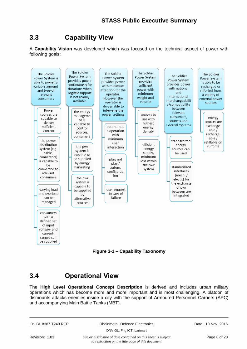
3.3 Capability View
A Capability Vision was developed which was focused on the technical aspect of power with following goals:
Figure 3-1 – Capability Taxonomy
3.4 Operational View
The High Level Operational Concept Description is derived and includes urban military operations which has become more and more important and is most challenging. A platoon of dismounts attacks enemies inside a city with the support of Armoured Personnel Carriers (APC) and accompanying Main Battle Tanks (MBT).

STASS Public Executive Summary
ID: BL 8387 T249 REP Rheinmetall Defence Electronics
DNV GL, Fhg ICT, Larimart
Date: 10 Nov. 2016
Revision: 1.03 Use or disclosure of data contained on this sheet is subject
to restriction on the title page of this document Page 9 of 20
Figure 3-2 –High Level Operational Concept of DSS in Groups with Vehicles
STASS Public Executive Summary
ID: BL 8387 T249 REP Rheinmetall Defence Electronics
DNV GL, Fhg ICT, Larimart
Date: 10 Nov. 2016
Revision: 1.03 Use or disclosure of data contained on this sheet is subject
to restriction on the title page of this document Page 10 of 20
For Germany, the differences between units with dismounted soldiers were extracted and especially, the main characteristics of a light and a mechanized infantry were worked out.
Also, the UK roles and activities were analysed.
It is thus important that a soldier system shows the flexible to serve all these roles and fulfils all the specific requirements.
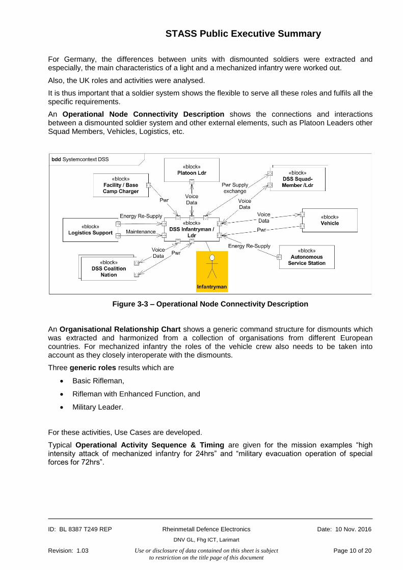
An Operational Node Connectivity Description shows the connections and interactions between a dismounted soldier system and other external elements, such as Platoon Leaders other Squad Members, Vehicles, Logistics, etc.
Figure 3-3 – Operational Node Connectivity Description
An Organisational Relationship Chart shows a generic command structure for dismounts which was extracted and harmonized from a collection of organisations from different European countries. For mechanized infantry the roles of the vehicle crew also needs to be taken into account as they closely interoperate with the dismounts.
Three generic roles results which are
Basic Rifleman,
Rifleman with Enhanced Function, and
Military Leader.
For these activities, Use Cases are developed.
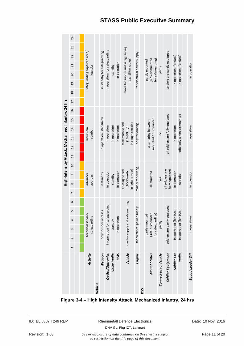
Typical Operational Activity Sequence & Timing are given for the mission examples “high intensity attack of mechanized infantry for 24hrs” and “military evacuation operation of special forces for 72hrs”.
STASS Public Executive Summary
ID: BL 8387 T249 REP Rheinmetall Defence Electronics
DNV GL, Fhg ICT, Larimart
Date: 10 Nov. 2016
Revision: 1.03 Use or disclosure of data contained on this sheet is subject
to restriction on the title page of this document Page 11 of 20
Figure 3-4 – High Intensity Attack, Mechanized Infantry, 24 hrs
12
34
56
78
91
01
11
21
31
41
51
61
71
81
92
02
12
22
32
4
Act
ivit
y
Ve
hic
le
Wea
po
n
Op
tics
/Op
tro
nic
s
Vo
ice
Ra
dio
BM
S
Veh
icle
Eng
ine
DSS
Mo
un
t St
atu
s
Co
nn
ecte
d t
o V
ehic
le
Sold
ier
Equ
ipm
ent
So
ldie
r C
4I
Ra
dio
Squ
ad
Lea
der
C4
I
Hig
h-I
nte
nsi
tiy
Att
ack,
Me
chan
ize
d I
nfa
ntr
y, 2
4 h
rs
tech
nic
al s
ervi
ce/
safe
guar
din
g
adva
nce
/
app
roac
h
incu
rsio
n/
com
bat
safe
guar
din
g ca
ptu
red
are
a/
logi
stic
s
on
ly f
or
spec
ial c
ases
in s
tan
db
yin
op
erat
ion
(st
abili
zed
)in
sta
nd
by
for
safe
guar
din
g
in o
per
atio
n f
or
safe
guar
din
gin
op
erat
ion
in o
per
atio
nin
op
erat
ion
fo
r sa
fegu
ard
ing
stan
db
yst
and
by
in o
per
atio
nst
and
by
in o
per
atio
nin
op
erat
ion
in o
per
atio
nin
op
erat
ion
mo
ve f
or
sup
ply
an
d s
afeg
uar
din
g
(e.g
. 15
km r
adiu
s)
for
elec
tric
al p
ow
er s
up
ply
mai
nly
fo
r d
rivi
ng
on
ly f
or
dri
vin
gfo
r el
ectr
ical
po
wer
su
pp
ly
mo
ve f
or
sup
ply
an
d s
afeg
uar
din
g
cru
isin
g sp
eed
(10
-30
km/h
in li
ght
terr
ain
)
max
imu
m s
pee
d
(10
-30
km/h
in r
ou
gh t
erra
in)
par
tly
mo
un
ted
(30
% d
ism
ou
nte
d
for
safe
guar
din
g)
all m
ou
nte
dal
tern
atin
g b
etw
een
mo
un
ted
/ d
ism
ou
nte
d
sold
iers
are
par
tly
equ
ipp
edal
l so
ldie
rs a
re
fully
eq
uip
ped
all s
old
iers
are
fu
lly e
qu
ipp
edso
ldie
rs a
re p
artl
y eq
uip
ped
par
tly
mo
un
ted
(60
% d
ism
ou
nte
d
for
safe
guar
din
g)
par
tly
yes
no
par
tly
in o
per
atio
n (
for
30
%)
in o
per
atio
nin
op
erat
ion
in o
per
atio
n (
for
60
%)
in o
per
atio
n (
for
30
%)
no
rad
iora
dio
on
ly w
hen
dis
mo
un
ted
in o
per
atio
n (
for
60
%)
in o
per
atio
nin
op
erat
ion
in o
per
atio
nin
op
erat
ion

STASS Public Executive Summary
ID: BL 8387 T249 REP Rheinmetall Defence Electronics
DNV GL, Fhg ICT, Larimart
Date: 10 Nov. 2016
Revision: 1.03 Use or disclosure of data contained on this sheet is subject
to restriction on the title page of this document Page 12 of 20
Finally, Non-Functional Requirements are formulated. Non-functional requirements do normally not belong to the Operational View but were added here in order to capture such requirements which also play an important role when designing a system.
Figure 3-5 – Non-functional requirements taxonomy

STASS Public Executive Summary
ID: BL 8387 T249 REP Rheinmetall Defence Electronics
DNV GL, Fhg ICT, Larimart
Date: 10 Nov. 2016
Revision: 1.03 Use or disclosure of data contained on this sheet is subject
to restriction on the title page of this document Page 13 of 20
3.5 Service Oriented View
Services with respect to power which shall be provided by the system are defined.
Figure 3-6 – Service Taxonomy
3.6 System View
Relevant devices were identified and assigned to be part of a core system, or part of additional enhancements for specific roles, but also devices which are shared within a squad.
Devices for specific roles and those shared within the squad required that the STASS extended the focus from the individual soldier to a squad of soldier. These devices are categorized into
Power Supply
o Power Sources (PS)

STASS Public Executive Summary
ID: BL 8387 T249 REP Rheinmetall Defence Electronics
DNV GL, Fhg ICT, Larimart
Date: 10 Nov. 2016
Revision: 1.03 Use or disclosure of data contained on this sheet is subject
to restriction on the title page of this document Page 14 of 20
o Bulk Charger (BC) for rechargeables
Consumers
o Low Power Consumers (LPC; <2.5W))
o Medium Power Consumers (MPC; 2.5W – 15W)
o High Power Consumers (HPC; >15W)
Power Distribution and Management
o Soldier Power Distribution, Control and Information (SDCI)
The SDCI may consist of separate smaller DCIs which have their own Central Rechargeable Battery (CRB), consumers attached and possibilities to connect further Power Sources (especially other DCIs).
Such smaller DCIs could be
a personal soldier DCI (On-Soldier DCI),
a weapon DCI,
a backpack DCI, and
a helmet DCI.
Figure 3-7 – Central Power Distribution, Information and Control “Cloud” (Connections to power sources (red), consumer devices (green), and
one or two Central Rechargeable Batteries (blue+grey)
The personal soldier DCI shall only support Low and Medium Power Consumers (LPCs and MPCs). Because power consumption of High Power Consumers (HPCs) would be unreasonably high to a personal soldier DCI, they need their own Power Source or, alternatively, a dedicated DCI.
It is essential that Soldier Systems can be provided with extra power in case the Rechargeable Central Battery (CRB) runs out of power. Besides providing fully charged replacement batteries, it is a desire to be also able to connect a wide range of power source, such as
Mobile Power Generators,
Energy Harvesting Devices,

STASS Public Executive Summary
ID: BL 8387 T249 REP Rheinmetall Defence Electronics
DNV GL, Fhg ICT, Larimart
Date: 10 Nov. 2016
Revision: 1.03 Use or disclosure of data contained on this sheet is subject
to restriction on the title page of this document Page 15 of 20
Platform Power (e.g. vehicle power), or even
standard primary batteries (e.g. from local stores).
An External Power Adapter (EPA) is suggested to condition the power and convert it from “dirty” Power (8-36V) to “clean” power within the voltage ranges needed in the DCIs (8-18V).
A Bulk Charger is defined in order to charge the rechargeable batteries and has an EPA functionality for the input such that it is able to connect to a wide range of Power Sources.
A completely equipped Soldier System with its possible connections and interfaces and with focus on power is shown below.
Figure 7-8 – Soldier System - Power
Most importantly, interfaces have been identified and grouped into:
Clean Power Sources,
Dirty power sources (External Power Adapter; EPA),
Bulk charger input,
Low and Medium Power USB 2.0,
Medium Power 100Mb/s Ethernet,
Central Rechargeable Battery,
High Power Consumers.

STASS Public Executive Summary
ID: BL 8387 T249 REP Rheinmetall Defence Electronics
DNV GL, Fhg ICT, Larimart
Date: 10 Nov. 2016
Revision: 1.03 Use or disclosure of data contained on this sheet is subject
to restriction on the title page of this document Page 16 of 20
For these interfaces characteristics, requirements and pin assignments are suggested. As only very few standards for soldier systems connectors exist, standardisation for such connectors incl. finalization of pin assignment is highly recommended and would allow interoperable connectors from multiple suppliers.
As the NATO Generic Vehicle Architecture is becoming more and more common inside vehicles, it would be necessary to define an interface to dismounted soldier systems. NGVA defines a reference architecture for fully networked mission systems inside military vehicles. Especially when a dismounted soldier is mounted, he needs to connect to the vehicle in order
to receive power (charging or charge retention),
to exchange data, and
to communicate by voice.
It is recommended to standardize such a connector which shall be different than the standard NGVA Power Connector. The NGVA Power Connector is suited for vehicles and is much too large for dismounted soldiers. It is also not desired that the dismounted soldier directly connects to the NGVA network as this generally is highly optimized and trimmed for the required performance. There shall be a dismounted soldier bus which is separated by a dismounted soldier gateway.
Figure 3-9 – Extending the Vehicle’s NGVA Network with a Soldier System Network via Internal Gateway
Vehicle’s NGVA Network
Vehicle’s Soldier System Network
Video & Audio
Status & Control
Safety Critical Data
Secured Links
Software Data Bus
Transport Services API + Data Model
Transport Services API + Data Model
Crew Interfaces (incl. C4I) Sensors Weapons &
Effectors
Data
Processing
Data
Storage
Diagnosis,
Maintenance &
Logistics
Training &
Simulation
Legacy System
Adapter
Onboard
Comms
Vehicle Platform
Interface (incl. HUMS)
Internal Gateways
Safety
GW
Cross Domain
GW
otherGW
Offboard
Comms
External
Gateways
Dismounted
Soldiers
Dismounted
Unmanned
Vehicles
Other Vehicles &
Headquarters
Interactive Electro.
Techn. Publications
Data ModelData
Streaming
Vehicle Sub-Systems
Crew Station
Sensors
Effectors
Common
C4I
Data StorageTraining & Simulation
Data Processing
Voice Communication
Data
Power
Mounted
Soldiers
Mounted
Soldiers
STASS Public Executive Summary
ID: BL 8387 T249 REP Rheinmetall Defence Electronics
DNV GL, Fhg ICT, Larimart
Date: 10 Nov. 2016
Revision: 1.03 Use or disclosure of data contained on this sheet is subject
to restriction on the title page of this document Page 17 of 20
3.7 Technical View
3.7.1 Technologies
3.7.1.1 Power Sources
Rechargeable batteries will continue to be the dominant power source for dismounted soldier system. With lithium ion technology, the energy density of secondary batteries has achieved a level that rendered the use of rechargeable batteries a standard today.
Fuel cells can offer higher energy density than batteries with almost the same low signature level. Cell types based on proton exchange membrane technology and using either hydrogen or methanol as fuel are quite mature. Fuel cells using logistic fuels are however on an early stage of development.
In contrast to batteries most fuel cells will require mechanical active components. However, operation at part load will cause significant reduction of efficiencies. As also the load following ability is limited, fuel cells cannot replace batteries in a dismounted soldier system but only act as complimentary power source and for battery charging unless each device is equipped with a backup battery.
Thermoelectric Generators have a low efficiency, but in case of burning high energy fuels such as Diesel, the trade-off between weight and energy becomes attractive. They are planned to be used in the NLD as additional power source.
Heat Engines use a combustion engine to generate power and are rather more suited to recharge a squad’s batteries because they are normally heavy with a larger size. Smaller, man-wearable ones are reported but they do not play a major role yet.
Energy Harvesting Devices come in very different sizes, from wind turbines, solar panels to knee and heel kinetic devices. However, the man wearable versions just do not generate enough power for today’s soldier systems to be even considered. Larger devices are interesting to be used on squad level for charging batteries.
3.7.1.2 Power Distribution
Wired power transfer is the current state of the art. E-textiles could be an interesting alternative reducing weight burden and even more bending resistance in the clothing.
Wireless power transfer seems to be an attractive alternative. However, it will also cause issues with respect to electromagnetic interference EMI as well as possible health implications. Wireless transmission is most beneficial be used to replace connectors avoiding connection failures due to dirt or bended pins and accelerating the connection.
3.7.1.3 Power Management
For Power Management, a very few systems are available. As power is only a part of an electrical, electronic, and IT based soldier system, a box performing power management only is not very useful. A central box to which all devices can be connected and which also supports data communication such as an USB or Ethernet Hub would be a solution. Further, most of the devices which need to be connected to such a box have their own power management already included. An overall management of a distributed power management system should be the ideal solution but cannot be achieved just looking at power only.

STASS Public Executive Summary
ID: BL 8387 T249 REP Rheinmetall Defence Electronics
DNV GL, Fhg ICT, Larimart
Date: 10 Nov. 2016
Revision: 1.03 Use or disclosure of data contained on this sheet is subject
to restriction on the title page of this document Page 18 of 20
For batteries, SMBus technology is used to access characteristics, the charging status, etc. from a battery. Such batteries are called Smart Batteries which are standard in any soldier system today.
3.7.1.4 Integrated Power and Data Transfer
It is important to use Integrated Power and Data Transfer in order to reduce the number of connectors and cables. Most of today’s systems use USB 2.0 and Ethernet with 100Mb/s. However, USB 2.0 does not always provide enough power and Ethernet does not provide power at all in its original standards. For interface standardisation, a combination of power and data transfer is essential.
3.7.2 Standards
In the Technical Standards Profile list potentially applicable standards are collected and listed in tables for
Open Architecture,
Interoperability,
Data Communication,
Safety,
Testing,
Smart Battery,
Power Quality,
Energy / Power Management,
Product Conformity, and
Laws and Regulations.
Although most of the standards are discussed in the background view and system view, other standards for
safety,
testing, and
interoperability
are considered as important and further analysed.
For safety, the protection classes from IEC 61140 are considered. Class 3 covers voltages up to 60VDC which can be installed without isolation to a user. Class 3 also specifies voltages up to 12VDC which is applicable to wet environments. The requirements for soldier systems mostly contain that soldiers need to be able to pass a river and thus being under water up to 1m. Further investigations would be necessary here. For charging, higher voltages are necessary and would be allowed as a soldier shall not be under water when charging.
Also safety standard for batteries are analysed, e.g. IEC 61233. For protective housing IEC 60529 is of relevance. Occupational Health and Safety Standards are listed in the standard profile tables.

STASS Public Executive Summary
ID: BL 8387 T249 REP Rheinmetall Defence Electronics
DNV GL, Fhg ICT, Larimart
Date: 10 Nov. 2016
Revision: 1.03 Use or disclosure of data contained on this sheet is subject
to restriction on the title page of this document Page 19 of 20
Testing standards provide useful requirements as they specify categories which a system needs to fulfil, such as climate and environmental testing (STANAG 4370). Especially, electrochemical batteries are sensitive to extreme temperatures which need to be considered.
Standards relevant for interoperability cover EMC standards and noise limits for Voltage sources. However, there are standards for the Voltage quality for land vehicles and aircrafts but not for soldier systems. This is clearly a gap.
The Advanced Configuration & Power Interface (ACPI) for computers is a standard which might be the basis for a Power Management standard for soldier systems.
Finally, standardisation gaps are identified:
Overall Safety
o Allowable Soldier System Voltages
Power Distribution and Management
o Soldier System Connectors
o Soldier System Power Qualities
o DC/DC-Converter Frequencies for Soldier Systems
o Data Communication Standards for Power Management on Soldier Systems
Power Sources
o Battery Charging
Power Factor Requirements for Soldier System Battery Chargers
o Battery Safety
Allowable Gas Emissions from Secondary Batteries in case of Hazard
Acceptable Lithium Ion Battery Hazard Levels for DSS or Sub-Systems
Harmonised regulation for the transport of damaged batteries
Fast Location and Removal of Worn Batteries for Dismounted Soldier
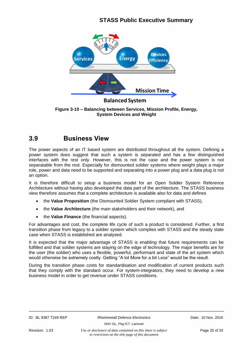
3.8 Target Architecture Design Guideline View
The Target Architecture Design Guideline View briefly discusses the differences between the civilian and the military market and a system design approach. It illustrates the trade-offs which are necessary.
STASS Public Executive Summary
ID: BL 8387 T249 REP Rheinmetall Defence Electronics
DNV GL, Fhg ICT, Larimart
Date: 10 Nov. 2016
Revision: 1.03 Use or disclosure of data contained on this sheet is subject
to restriction on the title page of this document Page 20 of 20
Figure 3-10 – Balancing between Services, Mission Profile, Energy, System Devices and Weight
3.9 Business View
The power aspects of an IT based system are distributed throughout all the system. Defining a power system does suggest that such a system is separated and has a few distinguished interfaces with the rest only. However, this is not the case and the power system is not separatable from the rest. Especially for dismounted soldier systems where weight plays a major role, power and data need to be supported and separating into a power plug and a data plug is not an option.
It is therefore difficult to setup a business model for an Open Soldier System Reference Architecture without having also developed the data part of the architecture. The STASS business view therefore assumes that a complete architecture is available also for data and defines
the Value Proposition (the Dismounted Soldier System compliant with STASS),
the Value Architecture (the main stakeholders and their network), and
the Value Finance (the financial aspects).
For advantages and cost, the complete life cycle of such a product is considered. Further, a first transition phase from legacy to a soldier system which complies with STASS and the steady state case when STASS is established are analysed.
It is expected that the major advantage of STASS is enabling that future requirements can be fulfilled and that soldier systems are staying on the edge of technology. The major benefits are for the user (the soldier) who uses a flexible, powerful, performant and state of the art system which would otherwise be extremely costly. Getting “A lot More for a bit Less” would be the result.
During the transition phase costs for standardisation and modification of current products such that they comply with the standard occur. For system-integrators, they need to develop a new business model in order to get revenue under STASS conditions.


