12
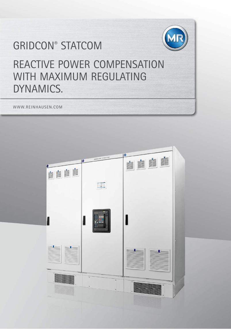
WWW.REINHAUSEN.COM GRIDCON ® STATCOM REACTIVE POWER COMPENSATION WITH MAXIMUM REGULATING DYNAMICS.
1
WWW.REINHAUSEN.COM
GRIDCON® STATCOM
REACTIVE POWER COMPENSATION WITH MAXIMUM REGULATING DYNAMICS.
2
GRIDCON® STATCOM
3
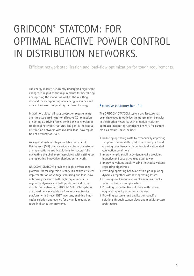
The energy market is currently undergoing significant changes in regard to the requirements for liberalizing and opening the market as well as the resulting demand for incorporating new energy resources and efficient means of regulating the flow of energy.
In addition, global climate protection requirements and the associated need for effective CO2 reduction are acting as driving forces behind the conversion of traditional network structures. The goal is innovative distribution networks with dynamic load-flow regula-tion at a variety of levels.
As a global system integrator, Maschinenfabrik Reinhausen (MR) offers a wide spectrum of customer and application-specific solutions for successfully navigating the challenges associated with setting up and operating innovative distribution networks.
GRIDCON® STATCOM provides a high-performance platform for making this a reality. It enables efficient implementation of voltage stabilizing and load-flow optimizing measures with high requirements for regulating dynamics in both public and industrial distribution networks. GRIDCON® STATCOM systems are based on a scaleable performance electronics platform with 3-level IGBT inverters, enabling inno-vative solution approaches for dynamic regulation tasks in distribution networks.
GRIDCON® STATCOM: FOR OPTIMAL REACTIVE POWER CONTROL IN DISTRIBUTION NETWORKS.
Efficient network stabilization and load-flow optimization for tough requirements.
Extensive customer benefits
The GRIDCON® STATCOM system architecture has been developed to optimize the transmission behavior in distribution networks with a modular solution approach, generating significant benefits for custom-ers as a result. These include: I Reducing operating costs by dynamically improving
the power factor at the grid connection point and ensuring compliance with contractually stipulated connection conditions
I Improving grid stability by dynamically providing inductive and capacitive regulated power
I Improving voltage stability using innovative voltage regulating algorithms
I Providing operating behavior with high regulating dynamics together with low operating losses
I Ensuring low harmonic current emissions thanks to active built-in compensation
I Providing cost-effective solutions with reduced engineering and production expenses
I Providing customer and application-specific solutions through standardized and modular system architecture
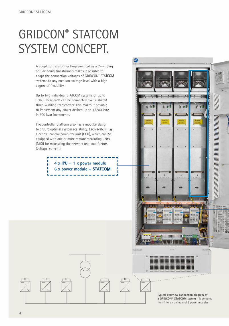
4 x IPU = 1 x power module6 x power module = STATCOM
Typical overview connection diagram of a GRIDCON® STATCOM system – it contains from 1 to a maximum of 6 power modules
GRIDCON® STATCOM
4
GRIDCON® STATCOMSYSTEM CONCEPT.
A coupling transformer (implemented as a 2-winding or 3-winding transformer) makes it possible to adapt the connection voltages of GRIDCON® STATCOM systems to any medium-voltage level with a high degree of fl exibility.
Up to two individual STATCOM systems of up to ±3600 kvar each can be connected over a shared three-winding transformer. This makes it possible to implement any power desired up to ±7200 kvar in 600 kvar increments.
The controller platform also has a modular design to ensure optimal system scalability. Each system has a central control computer unit (CCU), which can be equipped with one or more remote measuring units (MIO) for measuring the network and load factors (voltage, current).
6 x power module = STATCOM
STATCOMSYSTEM CONCEPT.
A coupling transformer (implemented as a 2-winding
STATCOM systems to any medium-voltage level with a high
3600 kvar each can be connected over a shared three-winding transformer. This makes it possible to implement any power desired up to ±7200 kvar
The controller platform also has a modular design to ensure optimal system scalability. Each system has a central control computer unit (CCU), which can be equipped with one or more remote measuring units (MIO) for measuring the network and load factors
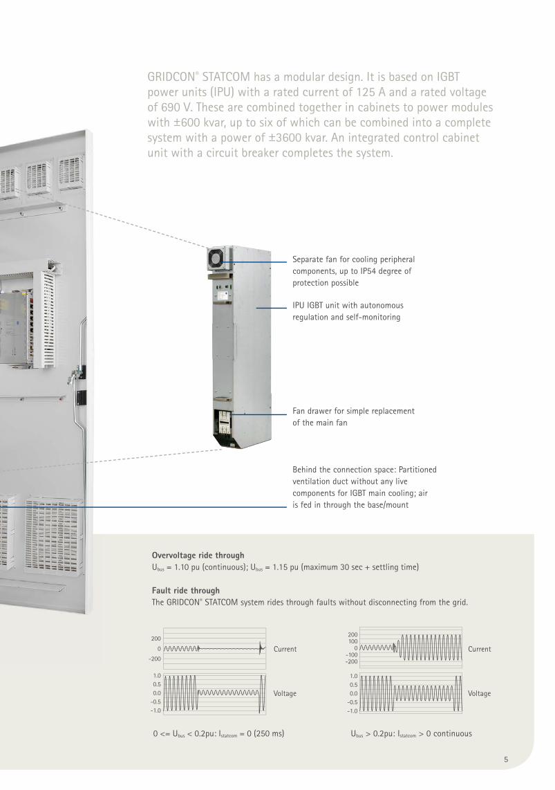
IPU IGBT unit with autonomousregulation and self-monitoring
Fan drawer for simple replacementof the main fan
Behind the connection space: Partitioned ventilation duct without any live components for IGBT main cooling; air is fed in through the base/mount
Separate fan for cooling peripheral components, up to IP54 degree of protection possible
Overvoltage ride through Ubus = 1.10 pu (continuous); Ubus = 1.15 pu (maximum 30 sec + settling time)
Fault ride throughThe GRIDCON® STATCOM system rides through faults without disconnecting from the grid.
200
0
-200
200100
0-100-200
1.00.50.0
-0.5-1.0
1.00.50.0
-0.5-1.0
Current Current
Voltage Voltage
0 <= Ubus < 0.2pu: Istatcom = 0 (250 ms) Ubus > 0.2pu: Istatcom > 0 continuous
5
GRIDCON® STATCOM has a modular design. It is based on IGBT power units (IPU) with a rated current of 125 A and a rated voltage of 690 V. These are combined together in cabinets to power modules with ±600 kvar, up to six of which can be combined into a complete system with a power of ±3600 kvar. An integrated control cabinet unit with a circuit breaker completes the system.
6
GRIDCON® STATCOM
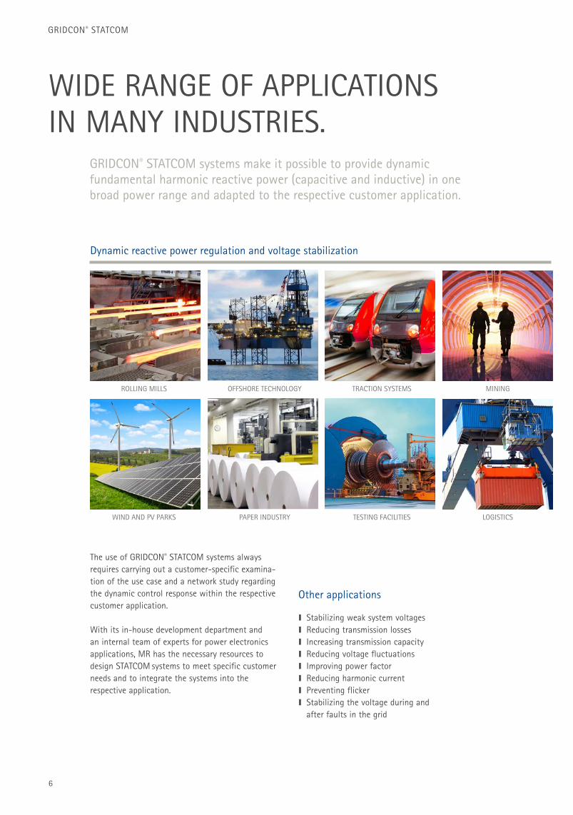
WIDE RANGE OF APPLICATIONS IN MANY INDUSTRIES.
GRIDCON® STATCOM systems make it possible to provide dynamic fundamental harmonic reactive power (capacitive and inductive) in one broad power range and adapted to the respective customer application.
Dynamic reactive power regulation and voltage stabilization
The use of GRIDCON® STATCOM systems always requires carrying out a customer-specific examina-tion of the use case and a network study regarding the dynamic control response within the respective customer application.
With its in-house development department and an internal team of experts for power electronics applications, MR has the necessary resources to design STATCOM systems to meet specific customer needs and to integrate the systems into the respective application.
Other applications
I Stabilizing weak system voltagesI Reducing transmission lossesI Increasing transmission capacityI Reducing voltage fluctuationsI Improving power factorI Reducing harmonic currentI Preventing flickerI Stabilizing the voltage during and
after faults in the grid
ROLLING MILLS
WIND AND PV PARKS
MINING
LOGISTICS
OFFSHORE TECHNOLOGY
PAPER INDUSTRY
TRACTION SYSTEMS
TESTING FACILITIES
7
READY AT ANY TIME – GRIDCON® STATCOM IN OFFSHORE OPERATIONS.
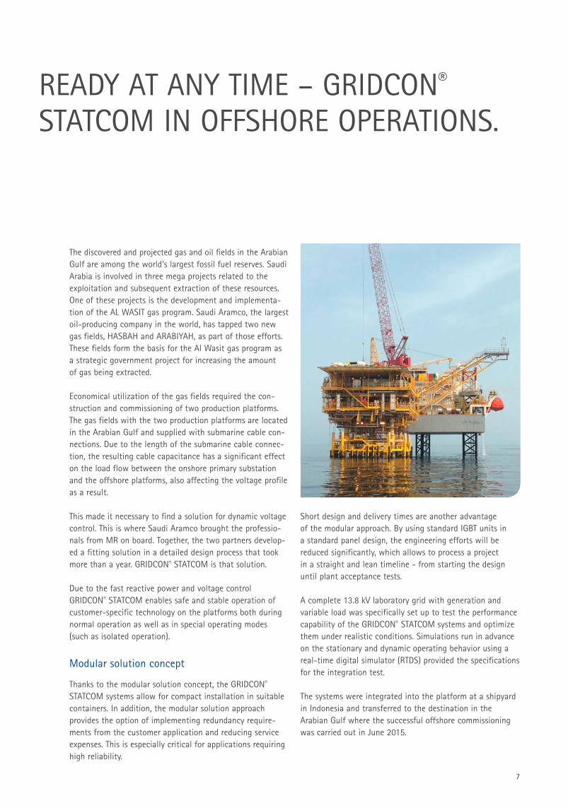
The discovered and projected gas and oil fields in the Arabian Gulf are among the world‘s largest fossil fuel reserves. Saudi Arabia is involved in three mega projects related to the exploitation and subsequent extraction of these resources. One of these projects is the development and implementa-tion of the AL WASIT gas program. Saudi Aramco, the largest oil-producing company in the world, has tapped two new gas fields, HASBAH and ARABIYAH, as part of those efforts. These fields form the basis for the Al Wasit gas program as a strategic government project for increasing the amount of gas being extracted.
Economical utilization of the gas fields required the con-struction and commissioning of two production platforms. The gas fields with the two production platforms are located in the Arabian Gulf and supplied with submarine cable con-nections. Due to the length of the submarine cable connec-tion, the resulting cable capacitance has a significant effect on the load flow between the onshore primary substation and the offshore platforms, also affecting the voltage profile as a result.
This made it necessary to find a solution for dynamic voltage control. This is where Saudi Aramco brought the professio-nals from MR on board. Together, the two partners develop-ed a fitting solution in a detailed design process that took more than a year. GRIDCON® STATCOM is that solution.
Due to the fast reactive power and voltage control GRIDCON® STATCOM enables safe and stable operation of customer-specific technology on the platforms both during normal operation as well as in special operating modes (such as isolated operation).
Modular solution concept
Thanks to the modular solution concept, the GRIDCON® STATCOM systems allow for compact installation in suitable containers. In addition, the modular solution approach provides the option of implementing redundancy require-ments from the customer application and reducing service expenses. This is especially critical for applications requiring high reliability.
Short design and delivery times are another advantage of the modular approach. By using standard IGBT units in a standard panel design, the engineering efforts will be reduced significantly, which allows to process a project in a straight and lean timeline - from starting the design until plant acceptance tests.
A complete 13.8 kV laboratory grid with generation and variable load was specifically set up to test the performance capability of the GRIDCON® STATCOM systems and optimize them under realistic conditions. Simulations run in advance on the stationary and dynamic operating behavior using a real-time digital simulator (RTDS) provided the specifications for the integration test.
The systems were integrated into the platform at a shipyard in Indonesia and transferred to the destination in the Arabian Gulf where the successful offshore commissioning was carried out in June 2015.
GRIDCON® STATCOM
8
IMPRESSIVE TECHNOLOGY – DEPENDABLE PERFORMANCE.
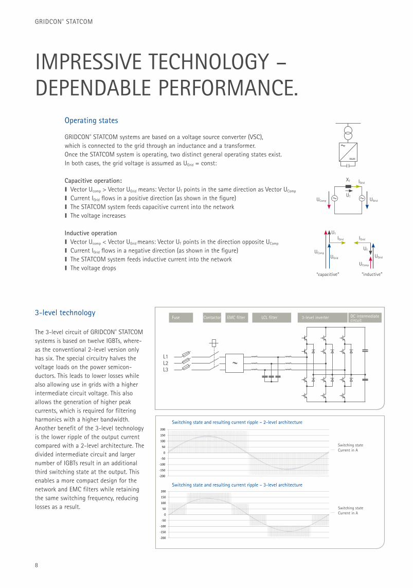
GRIDCON® STATCOM systems are based on a voltage source converter (VSC), which is connected to the grid through an inductance and a transformer. Once the STATCOM system is operating, two distinct general operating states exist. In both cases, the grid voltage is assumed as UGrid = const:
Capacitive operation: I Vector Ucomp > Vector UGrid means: Vector UT points in the same direction as Vector UComp
I Current IGrid flows in a positive direction (as shown in the figure) I The STATCOM system feeds capacitive current into the networkI The voltage increases
Inductive operation I Vector Ucomp < Vector UGrid means: Vector UT points in the direction opposite UComp
I Current IGrid flows in a negative direction (as shown in the figure) I The STATCOM system feeds inductive current into the networkI The voltage drops
The 3-level circuit of GRIDCON® STATCOM systems is based on twelve IGBTs, where-as the conventional 2-level version only has six. The special circuitry halves the voltage loads on the power semicon-ductors. This leads to lower losses while also allowing use in grids with a higher intermediate circuit voltage. This also allows the generation of higher peak currents, which is required for filtering harmonics with a higher bandwidth. Another benefit of the 3-level technology is the lower ripple of the output current compared with a 2-level architecture. The divided intermediate circuit and larger number of IGBTs result in an additional third switching state at the output. This enables a more compact design for the network and EMC filters while retaining the same switching frequency, reducing losses as a result.
Operating states
3-level technology
~ ~
XT
UT
UT
UT
IGrid
IGridIGrid
UGrid
UGridUGrid
UComp
UComp
”capacitive“ ”inductive“
UComp
50
100
150
200Schaltzustand und resultierender Ripple des Stroms ‐ 2 Level Architektur
SchaltzustandStrom in A
‐200
‐150
‐100
‐50
0
50 SchaltzustandStrom in A
‐200
100
150
200Schaltzustand und resultierender Ripple des Stroms ‐ 3 Level Architektur
‐150
‐100
‐50
0
50
100
SchaltzustandStrom in A
‐200
‐150
Switching stateCurrent in A
Switching stateCurrent in A
Switching state and resulting current ripple – 2-level architecture
Switching state and resulting current ripple – 3-level architecture
L1L2L3
~
Fuse Contactor EMC filter LCL filter 3-level inverter DC intermediate circuit
9
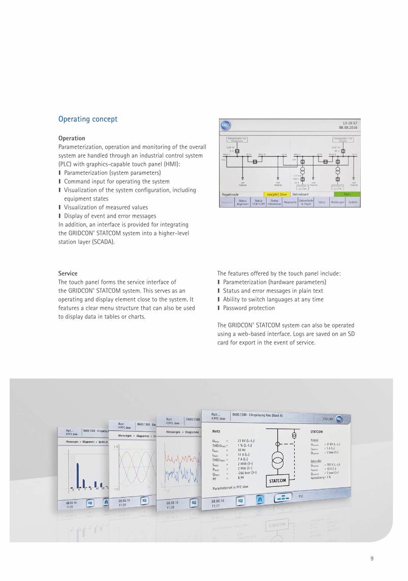
OperationParameterization, operation and monitoring of the overall system are handled through an industrial control system (PLC) with graphics-capable touch panel (HMI):I Parameterization (system parameters)I Command input for operating the system I Visualization of the system configuration, including
equipment statesI Visualization of measured valuesI Display of event and error messagesIn addition, an interface is provided for integrating the GRIDCON® STATCOM system into a higher-level station layer (SCADA).
ServiceThe touch panel forms the service interface of the GRIDCON® STATCOM system. This serves as an operating and display element close to the system. It features a clear menu structure that can also be used to display data in tables or charts.
Operating concept
The features offered by the touch panel include:I Parameterization (hardware parameters)I Status and error messages in plain textI Ability to switch languages at any timeI Password protection
The GRIDCON® STATCOM system can also be operated using a web-based interface. Logs are saved on an SD card for export in the event of service.
10
GRIDCON® STATCOM
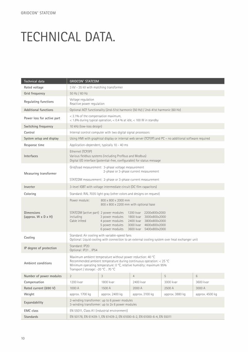
TECHNICAL DATA.
Technical data GRIDCON® STATCOM
Rated voltage 3 kV - 35 kV with matching transformer
Grid frequency 50 Hz / 60 Hz
Regulating functions Voltage regulationReactive power regulation
Additional functions Optional ACF functionality (2nd-51st harmonic (50 Hz) / 2nd-41st harmonic (60 Hz)
Power loss for active part < 2.1% of the compensation maximum, < 1.8% during typical operation, < 0.4 % at idle, < 100 W in standby
Switching frequency 10 kHz (low-loss design)
Control Internal control computer with two digital signal processors
System setup and display Using HMI with graphical display or internal web server (TCP/IP) and PC – no additional software required
Response time Application-dependent, typically 10 - 40 ms
InterfacesEthernet (TCP/IP)Various fi eldbus systems (including Profi bus and Modbus)Digital I/O interface (potential-free, confi gurable) for status message
Measuring transformer
Grid/load measurement: 3-phase voltage measurement 2-phase or 3-phase current measurement
STATCOM measurement: 2-phase or 3-phase current measurement
Inverter 3-level IGBT with voltage intermediate circuit (DC fi lm capacitors)
Coloring Standard: RAL 7035 light gray (other colors and designs on request)
Dimensions(approx. W x D x H)
Power module: 800 x 800 x 2000 mm 800 x 800 x 2200 mm with optional base
STATCOM (active part) 2 power modules 1200 kvar 2200x800x2000including 3 power modules 1800 kvar 3000x800x2000Cable infeed 4 power modules 2400 kvar 3800x800x2000 5 power modules 3000 kvar 4600x800x2000 6 power modules 3600 kvar 5400x800x2000
Cooling Standard: Air cooling with variable-speed fansOptional: Liquid cooling with connection to an external cooling system over heat exchanger unit
IP degree of protection Standard: IP20Optional: IP21 .. IP54
Ambient conditions
Maximum ambient temperature without power reduction: 40 °C Recommended ambient temperature during continuous operation: < 25 °C Minimum operating temperature: 0 °C, relative humidity: maximum 95%Transport / storage: -20 °C .. 70 °C
Number of power modules 2 3 4 5 6
Compensation 1200 kvar 1800 kvar 2400 kvar 3000 kvar 3600 kvar
Rated current (690 V) 1000 A 1500 A 2000 A 2500 A 3000 A
Weight approx. 1700 kg approx. 2400 kg approx. 3100 kg approx. 3880 kg approx. 4500 kg
Expandability 2-winding transformer: up to 6 power modules3-winding transformer: up to 2x 6 power modules
EMC class EN 55011, Class A1 (industrial environment)
Standards EN 50178, EN 61439-1, EN 61439-2, EN 61000-6-2, EN 61000-6-4, EN 55011
11
MORE POWER, MORE VALUE.GRIDCON® STATCOM – Dynamic reactive power compensation for the requirements of tomorrow.
The right solution for every application
I Implementation of customer-specifi c solutionsI Modular system approach enables power scaling up to 7.2 MvarI Comprehensive communications interfaces (MODBUS, Profi bus, IEC 61850)
for exchanging information with the customer’s on-site control systemI Compact design for high installation versatility (indoor, container)I Combinations with passive systems are available for system optimization
Maximum dependability and stability
I Redundancy at several levels (power module and individual IPUs)I Faults with a duration of up to 250 msec do not cause the STATCOM
to shut down (fault ride through)I Full dynamics even in the event that the grid voltage has experienced a
signifi cant drop of up to 20% below the rated voltage (fault ride through)I Compliance with the EMC requirements for industrial environments (EN 55011)
Low life-cycle costs
I Extremely low losses keep energy consumption low and reduce the effort and expense needed for climate control
I The guaranteed availability of spare parts ensures a long service life for the devicesI Long operating duration free of interruptions thanks to high-quality power
electronics components
Easy to service and operate
I Comprehensive MR service: Commissioning, system updating including system consulting as well as a variety of training options in our in-house technology
center for power electronicsI On-site support on short notice thanks to a global network of MR locationsI Integrated web server enables location-independent access to comprehensive
status and service informationI Customer-specifi c operating interface over PLC-based system controllerI Simple service for individual components thanks to modular system approachI Lasting fl exibility thanks to independent parameterization for new or modifi ed tasks
Maschinenfabrik Reinhausen GmbHFalkensteinstrasse 893059 Regensburg, GermanyPhone: +49 941 4090-0Fax: +49 941 4090-7001E-mail: [email protected]
LOW-VOLTAGE SOLUTIONS:Maschinenfabrik Reinhausen GmbHPower QualityWiebestr. 4610553 Berlin, GermanyPhone: +49 30 330915-0Fax: +49 30 330915-25E-mail: [email protected]
MEDIUM-VOLTAGE SOLUTIONS:Maschinenfabrik Reinhausen GmbHPower QualityAlte Chaussee 7399097 Erfurt, GermanyPhone: +49 361 30103-0Fax: +49 361 30103-20E-mail: [email protected]
www.reinhausen.com
THE POWER BEHIND POWER.
Please note:
The data in our publications may differ from
the data of the devices delivered. We reserve
the right to make changes without notice.
IN5040625/00 EN – GRIDCON® STATCOM –
F0339700 – 11/16 – uw
©Maschinenfabrik Reinhausen GmbH 2016


