44
Statecharts (hierarchical FSMs)
| Date post: | 08-Jul-2018 |
| Category: |
Documents |
| Upload: | truongphuc |
| View: | 219 times |
| Download: | 1 times |

Statecharts (hierarchical FSMs)

Hierarchical FSMs (Statecharts)
Introduced by D Harel (1987)
UML notation Stateflow notation

Hierarchical FSMs (Statecharts)
The FSM model presented until now can be extended by allowing
– Guards (conditions) and
– Actions on transitions
The original Statechart proposal added– Hierarchy
– Concurrency
– Communication
– Transition joins
– History and deep history states
Completed with– Entry,
– Exit,
– Do (while)
Actions on states

Transitions, conditions and actions (Stateflow)
• The following example shows the general label format for a transition entering a state:
• When an event occurs (combination of events), the condition for
the transition with a matching event ([condition]) is evaluated.
• If the condition condition evaluates to true, the condition action
condition_action ({condition_action}) is executed.
• If the destination state is determined to be a valid destination,
the transition is taken. State S1 is exited.
– The difference between condition and transition actions is more clear when junctions are involved
• The transition action transition_action is executed when the
transition is taken.
• State S2 is entered.
S1 S2event [condition] {condition_action} / transition_action
1

UML transitions
• UMl transitions are associated with a trigger event (or trigger operation), a guard (optional), an action (optional)

Hierarchical FSMs (Statecharts)
Motivation for hierarchy: a complex system cannot bedescribed naively in a flat, unstratified multitude of states, because of the very large number of such states.
A state-based approach must be modular, hierarchical and well structured, without having to represent explicitly the combination of all states
Need to handle statements as– “in all airborne states, when yellow handle is pulled, the seat will
be ejected” (cluster states into superstates)
– “gearbox change of state is independent from braking system”
(independence or orthogonality)
– “when selection button is pressed, enter selection mode”
(general transitions)
– Display mode consists of time-display, date-display and
stopwatch-display (refinement of states)

Hierarchical FSMs (Statecharts)
OR-clustering of states
A
C
B
D
B
D
α,δ
β
β
α
γ
δA
C
Bβ
α
γ
δ
β
Allows
abstraction
refines …
Same as …
(saves arrows)

Hierarchical FSMs (Statecharts)
Transitions that apply to all the states of a superstate
A
C
K
α
B
D
γ
E
β
δ
εεεε
φφφφ
A
C
K
α
B
D
γ
E
β
δ
φ
φ
φ
φ
φ, ε
ε
ε
ε
ε
Same as …
(saves arrows)
ε and φ apply to all states of K (A B C D E F )
H

Hierarchical FSMs (Statecharts)
AND-clustering of states
B
C
E
Y
α
A
G
F
D
β
α
δγ
µBE
CE
Y
α
BG BF
D
CG CF
βα
βα β
αγ
γ
µ
µ
δ
δ
Same as …
There is a considerable reduction in the
number of states and transitions.
α is taken synchronously!
(UML notation)
The subsystem is explicitly defined as a
number of FSM evolving in parallel

Statecharts: AND (parallel)states
• Stateflow notation for AND states

Hierarchical FSMs (Statecharts)
Transition and action inheritance
Inner states inherit the transitions and actions of parent states
if subS1 is active
events ev1 and ev2 are processed
according to the definitions of the
parent state
All during actions in the hierarchy are
executed

Inner and outer junctions
Difference between inner and outer transitions
• In inner transitions exit and entry statements are not executed
• In outer transitions, the state is exited and re-entered
• UML does not have inner transitions

Default transition, history and deep history state
A default transition is taken when a chart (subchart) is entered first.
Extends the concept of initial state providing an initial transition
Several options are possible for subcharted states
History state (H): the last active state in the current subchart
Deep history state (H*): the last active state in the current subchartand its subcharts (recursively)

State actions
States can have different action types, which include entry, during, exit, bind, and, on event_name actions.
In stateflow, the actions for states are assigned using the following general format:
name/
entry:entry actions
during:during actions
exit:exit actions
bind:data_name, event_name
on event_name:on event_name actions

State actions
Stateflow syntax
actions are preceded by the prefix or the short
prefix, followed by a required colon (:), followed by
one or more actions. Separate multiple actions
with a carriage return, semicolon (;), or a comma
(,). If you enter the name and slash followed
directly by actions, the actions are interpreted as
entry action(s).

State actions
Entry Actions (entry: or en:)
Entry actions are executed for a state when the state is entered(becomes active).
Exit Actions (exit: or ex:)
Exit actions for a state are executed when the state is active and a transition out of the state is taken.
During Actions (during: or du:)
During actions are executed for a state when it is active and anevent occurs and no valid transition to another state is available.
On Event_Name Actions (on event event_name:)
There can be multiple on event_name lines for different events. On event_name actions are executed when the state is active and the event event_name is received by the state. This is also accompanied by the execution of any during actions for the state.

State actions in UML
Entry Action
Exit Actions
Do activity
State invariant
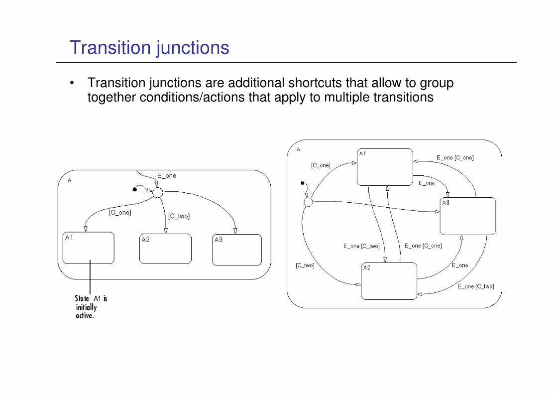
Transition junctions
• Transition junctions are additional shortcuts that allow to group together conditions/actions that apply to multiple transitions

Connective junctions
• To/from AND states

Connective junctions
Other types:
From Mathworks’ definition:
The connective junction enables representation of different possible transition paths for a single transition. Connective junctions are used to help represent the following:
– Variations of an if-then-else decision construct, by specifying conditions on some or all of the outgoing transitions from the connective junction
– A self-loop transition back to the source state if none of the outgoingtransitions is valid

Connective junctions
Other types:
– …
– Variations of a for loop construct, by having a self-loop transition from the connective junction back to itself
– Transitions from a common source to multiple destinations
– Transitions from multiple sources to a common destination
– Transitions from a source to a destination based on common events

Connective junctions
• Connective junctions can be used to define a
program dataflow

Backtracking on junctions
Transitions with junctions may force backtracking.
Initially, state A is active and conditions c1, c2, and c3 are true.
– Condition c1 is true, therefore action a1 is executed.
– Condition c3 is true, therefore action a3 is executed.
– Condition c4 is not true, therefore control flow is backtracked to state A.
– The Stateflow diagram root checks to see if there is another valid transitionfrom state A. There is a valid transition segment marked with the condition c2 from state A to a connective junction.
– Condition c2 is true, therefore action a2 is executed.
– Condition c3 is true, therefore action a3 is executed.
– Condition c4 is not true, therefore control flow is backtracked to state A.
Both a1 and a2 are executed, a3 is executed twice.

Backtracking on junctions
To resolve this problem, consider the following. The previous example is amended with two terminating junctions that allow flow to terminate if either c3 or c4 is not true. This leaves state A active without taking any unnecessary actions.

Transition junctions
Transitions with connective junctions and actions can be used to achieve the same expressive power of dataflows or standard programs (transition graphs).
– This often occurs and it is not recommended (unless truly needed)
Set Ramp Down Rate
{delta = In1 – In1_hist;}
Set Ramp Up Rate
[delta < Tran_Factor]
{ skip_sw_cycle = 0;
rate = (Ts*RAMP_50ms) + In1;}
[skip_sw_cycle = 0 || skip_sw_cycle >= 2]{ skip_sw_cycle = 1;}
Hold Ramp Up
{ skip_sw_cycle = skip_sw_cycle + 1;}
{ rate=(Ts*RAMP_100ms) + In1;}
[CL_CLIM < In1]{rate=(Ts*RAMP_100ms) + CL_CLIM;}
Find Min Rate
Set Output
{ RATE_out=rate;
TRAN_out = delta;
In1_hist=In1;}

Stateflow models
• Comment: not recommended for *many* reasons
– Typically not a specification, but an algorithmic description
– Hides the state view
– Hides side effects
– As difficult to debug and simulate as program!
– Not necessary

Run to completion vs. interruptible
• Simulink does not have a rtc semantics (UML does)
The end result for outval is 0

Stateflow semantics issues
• Possible infinite loop (recursion)
• Possible side effects

Stateflow – safety of models
• Absence of multi-segment loops when using junctions;
• Acyclicity of triggering and emitted events;
– Avoid internal events?
• No assignment of values to variables in intermediate
transition segments;
• Outgoing junction conditions form a cover;
• Outgoing junction conditions are disjoint;
• Assignment of different values to the same variable does
not occur in concurrent states (confluence);
• The model is free of early return logic.
• For more, check the MAAB guidelines…

Statecharts
Harel’s stopwatch

Stateflow
• a summary of the notation ….

SysML diagrams
SysML Diagram
Structure Diagram
Behavior Diagram
Requirement Diagram
Activity Diagrams
State Diagram
Sequence Diagram
Use case Diagram
Package Diagram
Internal Block Diagram
Block Definition Diagram
Parametric Diagram

UML diagrams

State Machine
• Used to represent the life cycle of a block
• event-based behavior (generally asynchronous)
Transition with trigger, guard, action
• State with entry, exit, and do-activity
• Can include nested sequential or concurrent states
• Can send/receive signals to communicate between
blocks during state transitions, etc.
• Event types
– Change event
– Time event
– Signal event

Elements of State Diagrams

Elements of State Diagrams
State: a condition of the
(sub)system typically
characterized by an invariant,
summarizing the history of the
previous inputs and defining its
mode of operation

Elements of State Diagrams
Composite State: contains at
least one region. Each region is
a concurrent superstate

Elements of State Diagrams
Submachine State: A
superstate for which the behavior
is defined by an internal state
machine

Elements of State Diagrams
Composite State: contains at
least one region. Each region is
a concurrent superstate
Orthogonal State: A superstate
for which the behavior is defined
by two or more concurrently
executing submachines, each in
its region

Elements of State Diagrams
Initial (pseudo) State: indicating
the initial state for the system,
there can be at most one in each
region

Elements of State Diagrams
Final state
Entry point
Exit point
Connection
pointreference
A pseudo-state signifying either the leaving state for
an object or the termination of the enclosing region
A reference for the target of a transition
A reference as the source of a transition
Used as a source or target of a transition. They
represent entries into or exits out of the submachinemachine referenced by the superstate.

Elements of State Diagrams
Fork
Join
Choicepoint
Junction
Splits an incoming transition into two or more transitions terminating on orthogonal target vertices
Merge transitions emanating from source vertices in
different orthogonal regions
Split transition paths (OR decomposition)
Chain together multiple transitions

State diagram vs Protocol state diagram

Example of state diagram


