Proceedings of COBEM 2009 Copyright c 2009 by ABCM 20th International Congress of Mechanical Engineering November 15-20, 2009, Gramado, RS, Brazil STATIC ANALYSIS OF THE RISERS-SOIL INTERACTION USING POSITIONAL FORMULATION Rafael Giovane Morini, [email protected]Renato Pavanello, [email protected]State University of Campinas - Unicamp, Cidade Universitária "Zeferino Vaz", Barão Geraldo - Campinas, Brazil, 13083-970. Abstract. One of the critical stages of offshore oil production process into deep water refers to the risers installation and operation. Particularly, for deep water with water layer higher than 2000 m where steel catenary riser may be a good choice. In this case, two nonlinear effects are specialy importants: large geometric non-linearity behavior from the line riser and soil-structure interaction in the seabed contact region. In this way, problems as behavior of risers and contact between the Steel Catenary Risers (SCR) and seabed, in marine studies, still require correct understanding. Thus, soil- fluid-structure interaction studies using a simple and effective tools is important to risers dynamics area. The proposal of this paper is to present one mechanical model to describe initially the static behaviour of SCR and one computational tool capable of representing the SCR contact with the seabed. For this way, a recent formulation named Positional Formulation was used to model a line riser. Positional Formulation is different from commonly used by workers because it is based on positions and not the displacement. It uses Lagrangian reference that is based on starting position of the body. This formulation is relatively simpler than those of custom and its implementation follows the same line. Newton-Raphson was used to solve the nonlinear system and Penalty Method was used to solve the contact problem. It was developed a comparative study about soil-structure interaction where were considered two specific conditions for displacement, linear and nonlinear, and two different soils, linear and bilinear. Always as possible the results obtained with the developed simulator were compared with existing literature. Keywords: risers, finite elements, positional formulation, static, soil. 1. INTRODUCTION Recently, Brazil has discovered a important oil reserve in the pre-salt layer. This discovery suggests large investments to exploit these reserves, among others because the oil reserve is under a water layer higher than 2000 m. The explotation in ultra high depth water layer demands high technology and efforts that allow reducing the cost of operation making it viable. To reduce operations costs is common to use computacional simulation in the design stage. Thus, there are softwares able to simulate some general cases, what is not the best thing to do in some cases like this that are very specifics. Most of then has been implemented using Finite Element Method [Bathe, 1982, Cook et al., 2002]. So, is common to find some dificulty to simulate this kind of problem, where is present non-linearity effect. In this way, this paper propose to use an alternative formulation to describe geometric nonlinear behavior and apply it for risers analysis. Nowadays, there are some formulations used to describe nonlinear problems but they usually are complex. For this reason, one new formulation named Positional Formulation [Coda, 2003a] based Finite Element Method propose to be less complex and more didatic. This work is the first stage of the project that the biggest aim is construct a simple and effective tool able to realize static and dynamic analysis of SCR with or without contact with the ground and including or not others effects. This paper presents a brief description of the Positional Formulation, which can be best assessed through references. In the sequence, a verification of the positional element of the beam is showed. Finally, a comparative study of simplified model proposed to evaluate the soil-structure interaction were done. In this study, the model was validated for a linear case, because it gives analytical solution and, subsequently, was evaluated for situations with large nonlinearities and then ground with linear and bilinear. 2. POSITIONAL FORMULATION The Positional Formulation is a new formulation developed recently aiming atempt difficultys found with geometric non-linearity [Coda, 2003a]. It is a relative simple and didatic formulation used to model engineering problems using finite element method (FEM). In this work, this formulation was used to describe beam elements with four nodes and three degrees of freedom per one. This formulation is basead in the principle of minimum potential energy that can be written using position considerations even displacements. In this way, the conservation law applied to an elastic medium results in Π= U e - P (1)
20th International Congress of Mechanical EngineeringNovember 15-20, 2009, Gramado, RS, Brazil
STATIC ANALYSIS OF THE RISERS-SOIL INTERACTION USINGPOSITIONAL FORMULATION
Rafael Giovane Morini, [email protected] Pavanello, [email protected] University of Campinas - Unicamp, Cidade Universitária "Zeferino Vaz", Barão Geraldo - Campinas, Brazil, 13083-970.
Abstract. One of the critical stages of offshore oil production process into deep water refers to the risers installation andoperation. Particularly, for deep water with water layer higher than 2000 m where steel catenary riser may be a goodchoice. In this case, two nonlinear effects are specialy importants: large geometric non-linearity behavior from the lineriser and soil-structure interaction in the seabed contact region. In this way, problems as behavior of risers and contactbetween the Steel Catenary Risers (SCR) and seabed, in marine studies, still require correct understanding. Thus, soil-fluid-structure interaction studies using a simple and effective tools is important to risers dynamics area. The proposal ofthis paper is to present one mechanical model to describe initially the static behaviour of SCR and one computational toolcapable of representing the SCR contact with the seabed. For this way, a recent formulation named Positional Formulationwas used to model a line riser. Positional Formulation is different from commonly used by workers because it is basedon positions and not the displacement. It uses Lagrangian reference that is based on starting position of the body. Thisformulation is relatively simpler than those of custom and its implementation follows the same line. Newton-Raphsonwas used to solve the nonlinear system and Penalty Method was used to solve the contact problem. It was developed acomparative study about soil-structure interaction where were considered two specific conditions for displacement, linearand nonlinear, and two different soils, linear and bilinear. Always as possible the results obtained with the developedsimulator were compared with existing literature.
Recently, Brazil has discovered a important oil reserve in the pre-salt layer. This discovery suggests large investmentsto exploit these reserves, among others because the oil reserve is under a water layer higher than 2000 m. The explotationin ultra high depth water layer demands high technology and efforts that allow reducing the cost of operation making itviable.
To reduce operations costs is common to use computacional simulation in the design stage. Thus, there are softwaresable to simulate some general cases, what is not the best thing to do in some cases like this that are very specifics. Mostof then has been implemented using Finite Element Method [Bathe, 1982, Cook et al., 2002]. So, is common to findsome dificulty to simulate this kind of problem, where is present non-linearity effect. In this way, this paper proposeto use an alternative formulation to describe geometric nonlinear behavior and apply it for risers analysis. Nowadays,there are some formulations used to describe nonlinear problems but they usually are complex. For this reason, one newformulation named Positional Formulation [Coda, 2003a] based Finite Element Method propose to be less complex andmore didatic.
This work is the first stage of the project that the biggest aim is construct a simple and effective tool able to realizestatic and dynamic analysis of SCR with or without contact with the ground and including or not others effects. This paperpresents a brief description of the Positional Formulation, which can be best assessed through references. In the sequence,a verification of the positional element of the beam is showed. Finally, a comparative study of simplified model proposedto evaluate the soil-structure interaction were done. In this study, the model was validated for a linear case, because itgives analytical solution and, subsequently, was evaluated for situations with large nonlinearities and then ground withlinear and bilinear.
2. POSITIONAL FORMULATION
The Positional Formulation is a new formulation developed recently aiming atempt difficultys found with geometricnon-linearity [Coda, 2003a]. It is a relative simple and didatic formulation used to model engineering problems usingfinite element method (FEM). In this work, this formulation was used to describe beam elements with four nodes andthree degrees of freedom per one. This formulation is basead in the principle of minimum potential energy that can bewritten using position considerations even displacements. In this way, the conservation law applied to an elastic mediumresults in
20th International Congress of Mechanical EngineeringNovember 15-20, 2009, Gramado, RS, Brazil
where Π is the total potential energy, Ue is the strain energy and P is the potential energy of the applied forces.In this case, will be used a linear constitutive relation with conjugate Green-Lagrange finite strain tensor and 2nd
Piola-Krchhof stress tensor. The strain energy can be written for the reference volume Vo as
Ue =∫
V0
ue dV0 (2)
where ue is the especific strain energy.The potencial energy of the applied forces can be calculed as, following:
P = FTi Xi (3)
where Fi is the force applied in each node and Xi is the set of positions independent of each other, it is important to notethat X may be occupied by a point of the body. Other point interisting is the fact that the potencial may not be zero in thereference.
In this way, is possible to write the equation of total potential energy as following:
Π =∫
V0
ue dV0 − FTi Xi (4)
Applying the equilibrium condition in the expression of total potential energy, Eq. (4), we can write:
∂Π∂Xi
=∫
V0
∂ue
∂XidV0 − Fi = 0 (5)
To solve this non linear problem the Newton-Raphson procedure was used. Thus, the Eq. (5) may be written in acompact notation
∂Π∂Xi
= gi(Xi) = fi(Xi)− Fi = 0 (6)
whereXi is a generealized parameter and indices are related to nodal positions by (1, 2, 3, 4, 5, 6, ...) = (X1, Y1,Θ1, X2, Y2,Θ2, ...).The next stage is solve the Eq. (6) using the Newton-Raphson procedure using Taylor expantion truncated in the first
term, thus, we can write
gi(Xi) = 0 ∼= gi(0Xi) +∇gi(0Xi)∆Xi (7)
or
∆Xi = −[∇gi(0Xi)]−1gi(0Xi) (8)
where [∇g(0Xi)] is the Hessian and g(0Xi) is the nodal force vector.In order to calculate the Hessian and the Nodal Force Vector the equations (9) and (10), respectively, are used.
∇gi(0X) =∫
V0
∂2ue
∂Xk∂XjdV0 (9)
and
gi(0X) =∫
V0
∂ue
∂XidV0 − Fi (10)
where Xi, Xj , Xk are nodal variables.More details of the Positional Formulation can be found in [Coda, 2003a, Coda, 2003b, Maciel, 2008].
2.1 Mapping the Beam
To map a beam using positional formulation is necessary to understand that should have a initial and final reference.It’s necessary too, to know that the method is basead in Lagragian Referencial, i.e., the initial reference never changes.An auxiliary non-dimensional space is used to map the beam. The Fig. 1 shows the auxiliary non-dimensional space usedto the mapping the beam.
20th International Congress of Mechanical EngineeringNovember 15-20, 2009, Gramado, RS, Brazil
We define three reference spaces: B0 represent the initial position, (ξ, η) is the isoparametric referencial and B1
represent the actual position. To transforme the quantities from the B0 to the B1 spaces is necessary to use a non-dimensional isoparametric space (ξ, η). So, is necessary to define the gradient operators A0 e A1, [Coda, 2003a].
Figure 1. Auxiliary Non-Dimensional Space
A mathematical combination for the Jacobian operator, A = A1A−10 , allow relate the initial and final states.
Now, is possible to describe the beam basead in position in this paper, Reissner Beam Model was used. Ai is thegradient matrix. The Fig. 2 shows the mapping of the beam.
Figure 2. Mapped of the beam.
The beam geometry may be represented, in the initial reference, by the follow equations
X1 = φiX1i +
h0
2η cos(φiθ
0i ) (11)
Y1 = φiY1i +
h0
2η cos(φiθ
0i ) (12)
and, in the final reference, by the follow equations
X2 = φiX2i +
h0
2η cos(φiθi) (13)
Y2 = φiY2i +
h0
2η cos(φiθi) (14)
where φi is the shape function, h0 is the height of the beam, θi is the rotation. In the initial and final position will be theangle aproximation given by
20th International Congress of Mechanical EngineeringNovember 15-20, 2009, Gramado, RS, Brazil
where i is the number of the shape function and j represents initial and final position. Again, more detail can be found in[Coda, 2003a, Coda, 2003b, Maciel, 2008].
3. VERIFICATION AND VALIDATIION
First of all, the main idea was verify if the element would be able to ensure the nonlinear behaviour which some risercould be submitted. Thus, the beam element was analyzed to assess their performance. The Fig. 3 shows one examplewhich was applied a bending moment at the free end of the beam and clamped another end. The beam was fixed in theleft extremity and the moment was imposed in the right extremity. This was a qualitative test where the beam had 1.5 mlenght, inertia moment equal to 1.08x10⁻⁶ m4 , cross sectional area equal to 3.06x10⁻⁴ m2 and the bending momentapplied was 50 KNm. In this example, 19 load steps and a regular mesh with 5 elements where used.
Figure 3. Beam subjected to a bending moment in the end.
The bending moment was imposed until the body had completed one loop. The Fig. 3 shows the ability of the elementto solve this problem and demonstrated the capability to solve problems with large geometric nonlinear effects.
This element was evaluted with some works presented in literature. So, this is not the proposal of the work and moreinformations can be found in [Maciel, 2008, Morini, 2009].
4. RESULTS
This work propose a study the interaction between SCR and seabed, i.e, soil-structure interaction. The typical andgeneral configuration for 2D-SCR with soil interaction is showed by the Fig. 4. This figure present a suspended catenaryregion of the riser and a region of the pipe interacting with seabed for the global analysis, the seabed is normaly representedby simplified winkler model [Pesce & Martins, 2004, Barros et al., 2009, Aubeny & Biscontin, 2009]
Figure 4. General model for 2D-SCR with soil interaction.
To study the contact region between risers and soil it is possible to adapted a simple model with a straight pipe. Inthis simplified model, was considered a local model that could be compared with analitic results. Thus, half of this pipe is
20th International Congress of Mechanical EngineeringNovember 15-20, 2009, Gramado, RS, Brazil
supported by springs that represent the soil behavior and another half was considered free with the end simply supported.To ensure the weight force was considered a force uniformly distributed along the pipe. The Fig. 5 show the modelassumed.
Figure 5. Model proposed for interaction riser-soil.
It was considered two soil models, linear and bilinear, where the first one once turned on it would not be turned offwhile the second could turn on or off depending on whether the pipe was penetrating the soil. Both cases were solvedusing Penalty Method [Bazaraa & Shetty, 1979, Serpa, 1996, Morini, 2009] which considered known stiffness of the soil.Figure 6 shows both soils, at the left is presented a linear soil where is possible to percieve that springs continue active afterpipe detachment and at the right the bilinear soil is showed where springs do not continue active after pipe detachment.
The properties used to solve this problem are showed in the Tab. 1.
Figure 6. Soil Models - Linear(left) and Bilinear(right)
20th International Congress of Mechanical EngineeringNovember 15-20, 2009, Gramado, RS, Brazil
4.1 Linear Conditions - lower loads conditions
Initially, in order to validate the problem of contact with the ground, the first simulated example considered smalldisplacements and small rotations so that the results could be compared with results obtained by the finite element methodfor linear problems and analytical results. For both, was considered a lower load uniformly distributed load of 13.245Nmand 56 elements. Figure 7 and Fig.8 show the results for the displacement and bending moment, respectively. Threemodels are compared. The first model is a tridimensional continum finite element model to the soil with linear conditionsin the contact region, i.e, the riser and soil nodes are showed (FEM). The second model is a winkler analitical solution[Barros et al., 2009]. The third model is the actual solution based in Positional Formulation (PF).
Figure 7. Interaction Riser-Soil: displacement - linear conditions
Figure 8. Interaction Riser-Soil: bending moment - linear conditions
Through the results for linear conditions can be observed that there is a detachment of the pipe in the region close tozero, i.e, the region in which the touch of riser with the ground. Also, we find a strong gradient of the bending moment in
20th International Congress of Mechanical EngineeringNovember 15-20, 2009, Gramado, RS, Brazil
this region, due to sudden variation of conditions imposed on the riser.It appears that the models show similar results, and thus, the positional formulation can be used to evaluate linear
problems.
4.2 NonLinear Conditions - high loads conditions
In the next study developed was considered the same soil-structure model, but now with nonlinear conditions, i.e,the loading was changed allowing geometric nonlinear condition, thus, was considered a distributed load of 2649 N/m.The Fig. 9 and Fig.10 show displacement and bending moment obtained, respectively. In this case, we consider a linearbehavior of the riser-soil coupling.
Figure 9. Displacement - nonlinear conditions, with linear riser-soil coupling.
Figure 10. Bending Moment - nonlinear conditions, with linear riser-soil coupling.
In this case, it is possible to verify a larger displacement of the pipe in the touch down region and the bending momentbecomes softer and moves to the right, this should occur because the gradient of stiffness that represents the presence ofsoil and because the big loading impose to the pipe.
20th International Congress of Mechanical EngineeringNovember 15-20, 2009, Gramado, RS, Brazil
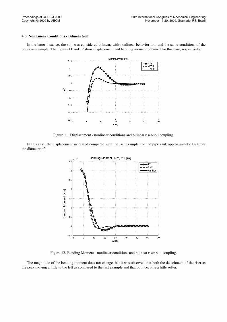
4.3 NonLinear Conditions - Bilinear Soil
In the latter instance, the soil was considered bilinear, with nonlinear behavior too, and the same conditions of theprevious example. The figures 11 and 12 show displacement and bending moment obtained for this case, respectively.
Figure 11. Displacement - nonlinear conditions and bilinear riser-soil coupling.
In this case, the displacement increased compared with the last example and the pipe sank approximately 1.5 timesthe diameter of.
Figure 12. Bending Moment - nonlinear conditions and bilinear riser-soil coupling.
The magnitude of the bending moment does not change, but it was observed that both the detachment of the riser asthe peak moving a little to the left as compared to the last example and that both become a little softer.
20th International Congress of Mechanical EngineeringNovember 15-20, 2009, Gramado, RS, Brazil
5. CONCLUSION
As mentioned in the introduction, the Positional Formulation provides a model relatively simple and intuitive, and canbe implemented with relative facility.
Based on the results obtained in the validation tests, we can conclude that the Positional Formulation can be applied tothe problems involving large geometric non-linearity effects. Furthermore, as expected, it solves linear problems as seenin the example linear.
The Positional Formulation was able to attend nonlinear problems, and has showed consistent results. The sameconclusion can be taken for problems involving effects of soil nonlinear, where the last example showed to be consistent.
Thus, the Positional Formulation is promising for application in the modeling of risers. May become an important toolfor analysis of risers.
Once completed this work, the next steps are: implement a 3D model, considering effects of Vortex Induced Vibrations(VIV), implementing new models of soil, among others.
6. ACKNOWLEDGEMENTS
The authors would like to thank the colaboration of Prof. Dr. Humberto Breves Coda in the technical supports aboutPositional Formulation.
The first author acknowledges the financial support he receives from the National Counsel of Technological andScientific Development (CNPq).
7. REFERENCES
Aubeny, C. P. & Biscontin, G. (2009). Seafloor-riser interaction model. International Journal of Geomechanics - ASCE.Barros, P. L. A., Morooka, C. K., Neto, E. M., & Pavanello, R. (2009). Scr-seafloor interaction modeling with winkler,
pasternak and kerr beam-on-elastic-foundation theories. Proceedings of OMAE09 28th- International Conference onOffshore Mechanics and Arctic Engineering.
Bathe, K. J. (1982). Finite Elements Procedures in Engineering Analysis. Englewood Cliffs - New Jersey: Prentice-Hall.Bazaraa, M. S. & Shetty, C. M. (1979). Nonlinear Programming - Theory and Algorithms. John Wile & Sons.Coda, H. B. (2003a). Análise não linear geométrica de sólidos e estruturas: Uma formulação posicional baseada no mef.
volume ii.Coda, H. B. (2003b). Notas de aula. Não Linearidade Geométrica.Cook, R. D., Malkus, D. S., & Plesha, M. E. (2002). Concepts and Applications of Finite Element Analysis. New York:
John Wile & Sons.Maciel, D. N. (2008). Análise de Problemas Elásticos Não Lineares Geométricos Empregando Método dos Elementos
Finitos Posicional. PhD thesis, Escola de Engenharia de São Carlos.Morini, R. G. (2009). Método dos elementos finitos posicional aplicado à análise estática de Risers. Master’s thesis,
Universidade Estadual de Campinas - Campinas.Pesce, C. P. & Martins, C. A. (2004). Riser-soil interaction: Local dynamics at tdp and a discussion on the eigenvalue and
the viv problems. ASME 23rd Inernational Conference on Offshore Mechanics and Arctic Engineering, (pp. ASMEPaper No. OMAE2004–51268).
Serpa, A. L. (1996). Problema de contato com atrito utilizando o método do lagrangiano aumentado. Master’s thesis,Universidade Estadual de Campinas - Campinas.