Journal of KONES Powertrain and Transport, Vol. 25, No. 1 2018 STATIC ANALYSIS OF THE TIPPER SEMI-TRAILER FRAME Jan Misiak, Sławomir Stachura University of Ecology and Management Olszewska Street 12, 00-792 Warsaw, Poland tel. +48 22 8258032 e-mail: [email protected], [email protected]Abstract The article presents a static analysis of the existing three-axle tipper semitrailer using the finite element method. The tipper trailer frame must be strong enough to carry loads from the load while driving, during an accident and especially when emptying the load box when a very large part of the load is pointing at the rear of the frame. Frames are usually made of low-alloy steel with increased strength, most often of grade S355J2G3; duralumin alloy frames are also used. The currently designed semi-trailer frames are becoming more lightweight while the required load capacity and durability are retained. This is possible thanks to the use of computational methods by the engineers in this finite element method. Static analysis allows for the determination of stress and deformation in the loaded frame and also a possible modification of the frame. The aim of the work was to investigate the influence of the position of the crossbar on the level of stress and deformations for three different load situations of the frame. Keywords: static balance, global static, web local buckling, Finite Element Method 1. Introduction Freight transport of loose materials utilizes tipper’s semitrailer and to increase their payload to 27000 kg (270 kN) and an acceptable loading axle of 80 kN (8000 kg), the chassis of the trailer has three axles. The use of pneumatic cushion in suspension makes easy to construct the beam stringers, transversal force loading the section crosses the centre of gravity and does not cause torsion of the stringer. The semi-trailer frame (Fig. 1) consists of two beam stringers with a fixed web height in the area connected to the three axles and a variable web height in the first crossbar area and the saddle, where the stringers are folded in the plan, are close to each other. The biggest height of the beam is 440 mm, intermediate 326 mm and the smallest 253 mm. In the area of the highest stiffness of the frame there are three axles, this is to cause transfer of the box loading to the road, through axles. The semi-trailer truck is designed to produce the driving force needed to drive the car kit. The loading part of the burden increase truck's driving axle load to 100 kN (10000 kg). The saddle area in the frame is stiffened by the gusset plate and the longitudinal and transverse ribs, this is the place of the trailer hitch in the truck's saddle and the stiffening is intended to prevent deformation, which would affect the safety of the coupling of the truck and the trailer. The cross bars have a complex cross-section, which includes three closed circuits, so they are rigid to twist and transfer torque between stringers. Torques are the effect of stringers bending moments of the longitudinal members, distinct bending stringers cause torsion of crossbars. For the frame was used steel with increased strength and guaranteed weldability S355J2G3, rated ductility limit = 355 and rated breaking strength = 510 . A model of static frame computation was performed using the Robot of the finite element method, with 26590 coating finite elements with unknown generalized displacements of 152030 degrees of freedom. ISSN: 1231-4005 e-ISSN: 2354-0133 DOI: 10.5604/01.3001.0012.2479
Transcript
Journal of KONES Powertrain and Transport, Vol. 25, No. 1 2018
STATIC ANALYSIS OF THE TIPPER SEMI-TRAILER FRAME
Jan Misiak, Sławomir Stachura
University of Ecology and Management Olszewska Street 12, 00-792 Warsaw, Poland
The article presents a static analysis of the existing three-axle tipper semitrailer using the finite element method. The tipper trailer frame must be strong enough to carry loads from the load while driving, during an accident and especially when emptying the load box when a very large part of the load is pointing at the rear of the frame. Frames are usually made of low-alloy steel with increased strength, most often of grade S355J2G3; duralumin alloy frames are also used.
The currently designed semi-trailer frames are becoming more lightweight while the required load capacity and durability are retained. This is possible thanks to the use of computational methods by the engineers in this finite element method. Static analysis allows for the determination of stress and deformation in the loaded frame and also a possible modification of the frame. The aim of the work was to investigate the influence of the position of the crossbar on the level of stress and deformations for three different load situations of the frame.
Keywords: static balance, global static, web local buckling, Finite Element Method
1. Introduction
Freight transport of loose materials utilizes tipper’s semitrailer and to increase their payload to27000 kg (270 kN) and an acceptable loading axle of 80 kN (8000 kg), the chassis of the trailer has three axles. The use of pneumatic cushion in suspension makes easy to construct the beam stringers, transversal force loading the section crosses the centre of gravity and does not cause torsion of the stringer.
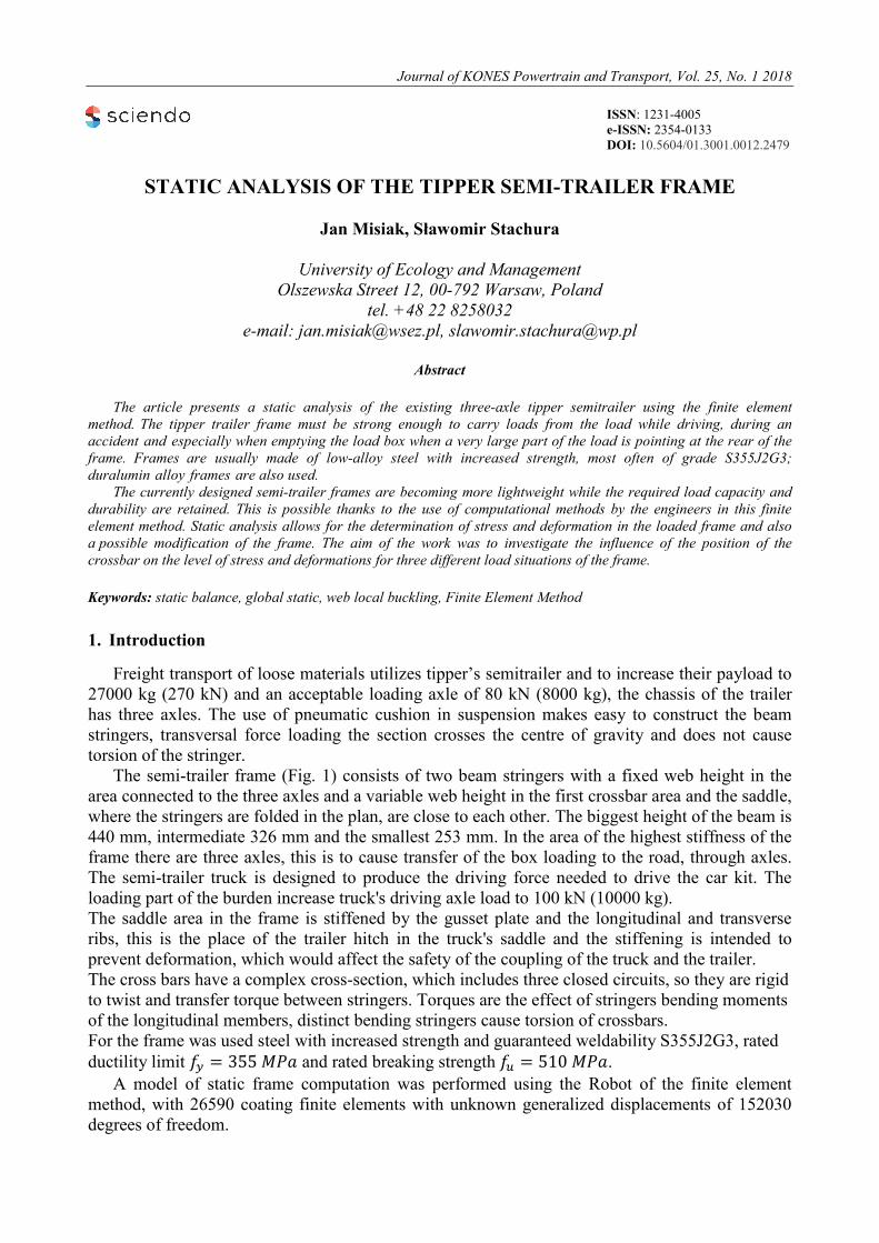
The semi-trailer frame (Fig. 1) consists of two beam stringers with a fixed web height in the area connected to the three axles and a variable web height in the first crossbar area and the saddle, where the stringers are folded in the plan, are close to each other. The biggest height of the beam is 440 mm, intermediate 326 mm and the smallest 253 mm. In the area of the highest stiffness of the frame there are three axles, this is to cause transfer of the box loading to the road, through axles. The semi-trailer truck is designed to produce the driving force needed to drive the car kit. The loading part of the burden increase truck's driving axle load to 100 kN (10000 kg). The saddle area in the frame is stiffened by the gusset plate and the longitudinal and transverse ribs, this is the place of the trailer hitch in the truck's saddle and the stiffening is intended to prevent deformation, which would affect the safety of the coupling of the truck and the trailer. The cross bars have a complex cross-section, which includes three closed circuits, so they are rigid to twist and transfer torque between stringers. Torques are the effect of stringers bending moments of the longitudinal members, distinct bending stringers cause torsion of crossbars. For the frame was used steel with increased strength and guaranteed weldability S355J2G3, rated ductility limit 𝑓𝑦 = 355 𝑀𝑀𝑀 and rated breaking strength 𝑓𝑢 = 510 𝑀𝑀𝑀.
A model of static frame computation was performed using the Robot of the finite element method, with 26590 coating finite elements with unknown generalized displacements of 152030 degrees of freedom.
Fig. 1. Scheme of a semi-trailer frame 2. Static calculations of the loaded frame
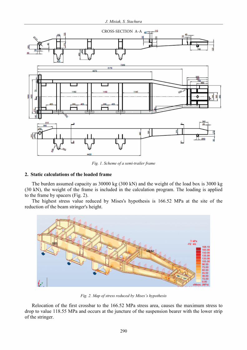
The burden assumed capacity as 30000 kg (300 kN) and the weight of the load box is 3000 kg (30 kN), the weight of the frame is included in the calculation program. The loading is applied to the frame by spacers (Fig. 2).
The highest stress value reduced by Mises's hypothesis is 166.52 MPa at the site of the reduction of the beam stringer's height.
Fig. 2. Map of stress reduced by Mises’s hypothesis
Relocation of the first crossbar to the 166.52 MPa stress area, causes the maximum stress to drop to value 118.55 MPa and occurs at the juncture of the suspension bearer with the lower strip of the stringer.
CROSS-SECTION A-A
290
Static Analysis of the Tipper Semi-Trailer Frame
Fig. 3. Map of stresses reduced by Mises's hypothesis, after changing the position of the first stringer
Moreover, displacement of the crossbar results in a reduction in stress from 166.52 MPa to 114.22 MPa in the same place, height graduation of the stringer, what is triggered by reduced deformation of the stringers, as the inserted crossbar limits this deformation. In the case of interim torsions triggering torsion in regard to the longitudinal axis of the frame, twist-flexural deformation occurs in the weakest area of the frame, between the reinforced side of the saddle and the first crossbar. Repair of this damage consists in removing the deformed parts by cutting off at the points of their joints, resulting from the height gradation of the cross-section of the stringer and replacing it with new parts.
Fig. 4. Deformation of the frame at the old crossbar position
Fig. 5. Deformation of the frame at the new crossbar position
291
J. Misiak, S. Stachura
By comparing the results of the deformation of the frame (Figs. 4 and 5), it is apparent that the value decreases from 3.77 cm to 0.2 cm, because the crossbar has been moved into the area of the biggest deformation (Fig. 5). The crossbar limits twist-flexural deformation of stringers.
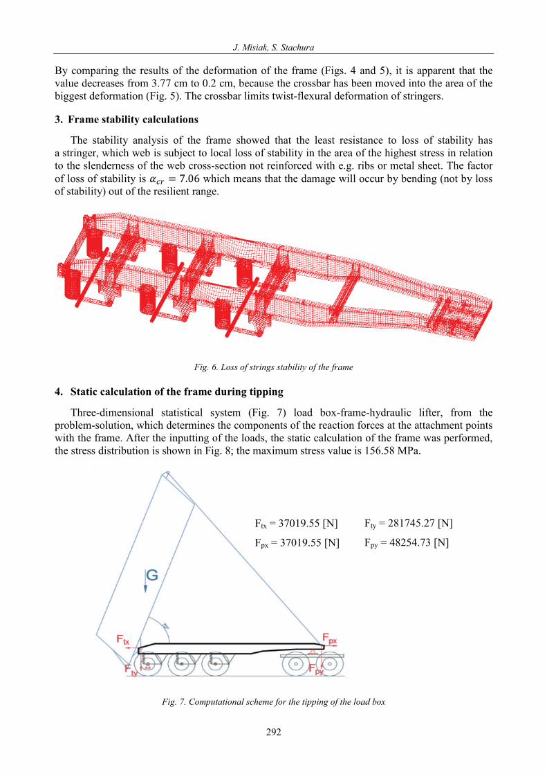
3. Frame stability calculations
The stability analysis of the frame showed that the least resistance to loss of stability hasa stringer, which web is subject to local loss of stability in the area of the highest stress in relation to the slenderness of the web cross-section not reinforced with e.g. ribs or metal sheet. The factor of loss of stability is 𝛼𝑐𝑐 = 7.06 which means that the damage will occur by bending (not by loss of stability) out of the resilient range.
Fig. 6. Loss of strings stability of the frame
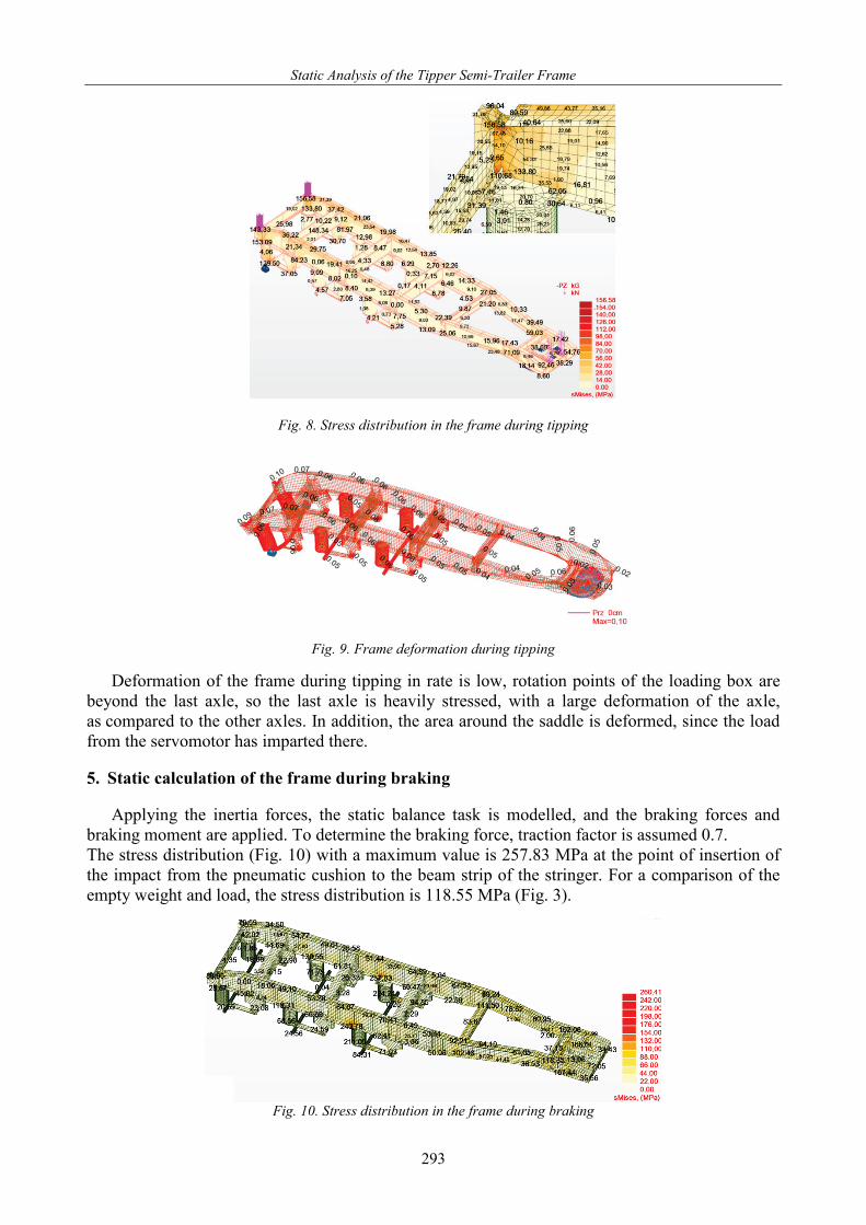
4. Static calculation of the frame during tipping
Three-dimensional statistical system (Fig. 7) load box-frame-hydraulic lifter, from theproblem-solution, which determines the components of the reaction forces at the attachment points with the frame. After the inputting of the loads, the static calculation of the frame was performed, the stress distribution is shown in Fig. 8; the maximum stress value is 156.58 MPa.
Fig. 7. Computational scheme for the tipping of the load box
Ftx = 37019.55 [N]
Fpx = 37019.55 [N]
Fty = 281745.27 [N]
Fpy = 48254.73 [N]
292
Static Analysis of the Tipper Semi-Trailer Frame
Fig. 8. Stress distribution in the frame during tipping
Fig. 9. Frame deformation during tipping
Deformation of the frame during tipping in rate is low, rotation points of the loading box are beyond the last axle, so the last axle is heavily stressed, with a large deformation of the axle, as compared to the other axles. In addition, the area around the saddle is deformed, since the load from the servomotor has imparted there. 5. Static calculation of the frame during braking
Applying the inertia forces, the static balance task is modelled, and the braking forces and
braking moment are applied. To determine the braking force, traction factor is assumed 0.7. The stress distribution (Fig. 10) with a maximum value is 257.83 MPa at the point of insertion of the impact from the pneumatic cushion to the beam strip of the stringer. For a comparison of the empty weight and load, the stress distribution is 118.55 MPa (Fig. 3).
Fig. 10. Stress distribution in the frame during braking
293
J. Misiak, S. Stachura
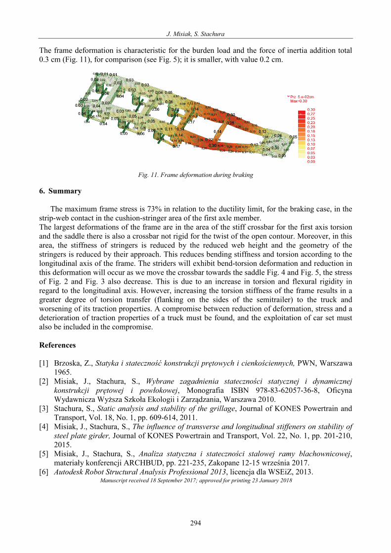
The frame deformation is characteristic for the burden load and the force of inertia addition total 0.3 cm (Fig. 11), for comparison (see Fig. 5); it is smaller, with value 0.2 cm.
Fig. 11. Frame deformation during braking
6. Summary
The maximum frame stress is 73% in relation to the ductility limit, for the braking case, in the strip-web contact in the cushion-stringer area of the first axle member. The largest deformations of the frame are in the area of the stiff crossbar for the first axis torsion and the saddle there is also a crossbar not rigid for the twist of the open contour. Moreover, in this area, the stiffness of stringers is reduced by the reduced web height and the geometry of the stringers is reduced by their approach. This reduces bending stiffness and torsion according to the longitudinal axis of the frame. The striders will exhibit bend-torsion deformation and reduction in this deformation will occur as we move the crossbar towards the saddle Fig. 4 and Fig. 5, the stress of Fig. 2 and Fig. 3 also decrease. This is due to an increase in torsion and flexural rigidity in regard to the longitudinal axis. However, increasing the torsion stiffness of the frame results in a greater degree of torsion transfer (flanking on the sides of the semitrailer) to the truck and worsening of its traction properties. A compromise between reduction of deformation, stress and a deterioration of traction properties of a truck must be found, and the exploitation of car set must also be included in the compromise.
References
[1] Brzoska, Z., Statyka i stateczność konstrukcji prętowych i cienkościennych, PWN, Warszawa 1965.
[2] Misiak, J., Stachura, S., Wybrane zagadnienia stateczności statycznej i dynamicznej konstrukcji prętowej i powłokowej, Monografia ISBN 978-83-62057-36-8, Oficyna Wydawnicza Wyższa Szkoła Ekologii i Zarządzania, Warszawa 2010.
[3] Stachura, S., Static analysis and stability of the grillage, Journal of KONES Powertrain and Transport, Vol. 18, No. 1, pp. 609-614, 2011.
[4] Misiak, J., Stachura, S., The influence of transverse and longitudinal stiffeners on stability of steel plate girder, Journal of KONES Powertrain and Transport, Vol. 22, No. 1, pp. 201-210, 2015.
[5] Misiak, J., Stachura, S., Analiza statyczna i stateczności stalowej ramy blachownicowej, materiały konferencji ARCHBUD, pp. 221-235, Zakopane 12-15 września 2017.
[6] Autodesk Robot Structural Analysis Professional 2013, licencja dla WSEiZ, 2013.
294
Manuscript received 18 September 2017; approved for printing 23 January 2018