36
ELECTRICAL AND ELECTRONINCS MEASUREMENTS
| Date post: | 07-Dec-2015 |
| Category: |
Documents |
| Upload: | anushya-ravikumar |
| View: | 238 times |
| Download: | 0 times |
ELECTRICAL AND ELECTRONINCS MEASUREMENTS
MEASUREMENT
The process of measuring is essentially that of comparing some unknown value with a value which is assumed to be known.
1) latter one in standard. 2) And measuring system is instrument.
Characteristics of INSTRUMENTS
Calibration: All the static characteristics are obtained in one form or another by a process called Calibration.
Calibration procedures involve a comparison of the particular instrument with either
a) a primary standard. b) a secondary standard with a higher
accuracy than the instruments be calibrated. c) an instrument of known accuracy.
Accuracy: Accuracy may be defined as the ability of a device or a system to respond to a true value of a measured variable under reference conditions.
Precision: Precision is defined by the degree of exactness for which an instrument is designed or intended to perform.
Repeatability: It is the closeness of agreement among a number of consecutive measurements of the output for the same value of the input, under the same operating conditions.
Reproducibility: It is the closeness of agreement among repeated measurements of the output for the same value of the input, made under the same operating conditions over a period of time.
Drift: It is an undesired change or a gradual variation in output over a period of time that is unrelated to changes in input and operating conditions.
Span: If in a measuring instrument the highest point of calibration is y units and the lowest point x units.
Then the instrument range y units The instrument span is given by Span=(x-y)units
Sensitivity: Sensitivity can be defined as the ratio of a change in output to the change in input which causes it.
Resolution: The smallest increment in input (the quantity being measured) which can be detected with certainty by an instrument is its resolution.
Dead zone: Dead zone is the largest range of values of a measured variable to which the instrument does not respond.
ERRORTypes of Error
Static Error : the numerical difference between the true value of a quantity and its value as obtained by measurement.
Mistakes: These are errors due to human mistakes such as careless reading, mistakes in observations, incorrect application of a correction, improper application of instruments and computational errors.
Systematic Error: 1)Instrumental Error: Instrumental errors are the
errors inherent in measuring instruments because of their mechanical structure, such as friction in bearings of various moving components, irregular spring tension.
2)Environmental Error: it is due to conditions external to the measuring device including conditions in the area surrounding the instrument such as the effect of change in temp , humidity, barometric pressure , or magnetic or electrostatic fields.
Random Error: the cause of such error is unknown or not determinable in the ordinary process of making measurements. Such errors are normally small and follows the laws of chance.
SOURCES OF ERROR
Insufficient knowledge of process parameters and design conditions.
Poor design. Poor maintenance. Error caused by people who operate
instrument equipment. Certain design limitations.
TYPES OF INSTRUMENTS Absolute Instruments: Absolute instruments are those which give the value of
the electrical quantity to be measured, in terms of the constant of the instruments and their deflection only, e.g. tangent galvanometer.
Secondary Instruments: Secondary instruments are those which have been
precalibrated by comparison with an absolute instrument. The value of the electrical quantity to be measured in these instruments can be determined from the deflection of the instrument.
Without calibration of such an instrument, the deflection is meaningless.
Different types of secondary instruments: 1)Indicating 2)Recording 3)Integrating
1)Indicating: Indicating instruments are those which indicate the
instantaneous value of the electrical quantity being measured, at the time at which it is being measured. Their indications are given by pointers moving over calibrated dials(scale), e.g. ammeters,voltmeters and wattmeters.
2)Recording: Recording instruments are those which give a continuous
record of variations of the electrical quantity over a selected period of time. The moving system of the instrument carries an inked pen which rests tightly on a graph chart. E.g. recording voltmeters used in supply station.
3)Integrating: Integrating instruments are those which measure and
register the total quantity of electricity (in ampere-hour) or the total amount of electrical energy(in watt-hours or kilowatt-hours) supplied to a circuit over a period of time, e.g. ampere-hour meters, energy meters.
ESSENTIALS OF INDICATING INSTRUMENTS
Deflecting Torque(Td): It is the torque which deflects the pointer on a
calibrated scale according to the electrical quantity passing through the instrument. The deflecting torque causes the moving system and hence the pointer attached to it to move from zero position to indicate on a graduated scale the value of electrical quantity being measured.
Controlling Torque(Tc): It is the torque which controls the movement of the
pointer on a particular scale according to the quantity of electricity passing through it. If deflecting torque were acting alone, the pointer would continue to move indefinitely and would swing over to the maximum deflected position irrespective of the magnitude of current (or voltage or power) to be measured.
1) Spring Control: In the spring control method, a hair-spring, usually of
phosphor-bronze, attached to the moving system is used. With the deflection of the pointer, the spring is twisted in the opposite direction. This twist in the spring produces a restoring torque which is directly proportional to the angle of deflection of the moving system. The pointer comes to a position of rest (or equilibrium) when the deflecting torque (Td) and controlling torque (Tc) are equal.
Tc ∞ θTo give a controlling torque which is directly proportional to the
angle of deflection of the moving system, the number of turns of the spring should be fairly large so that the deformation per unit length is small. The stress in the spring must be limited to such a value that there is no permanent set. Springs are made of materials which are
Non magnetic Not subject to much fatigue Low in specific resistance Have low temperature coefficient of resistance.
2) Gravity Control: Gravity control is obtained by attaching a small weight to the
moving system in such a way that it produces a restoring or controlling torque when the system is deflected.
Tc ∞ SinθThus, controlling torque in a gravity control system is proportional
to the sine of the angle of deflection.The degree of control is adjusted by screwing the weight up or
down on the carrying system.Advantages:The advantages of gravity control system, as compared to spring
control, are given below: It is cheap It is unaffected by temperature It is not subjected to fatigue or distortion, with time.Disadvantages:The disadvantages of gravity control system, as compared to
spring control, are given below: It gives a cramped scale. The instrument has to be kept vertical.
Damping Torque: If the moving system is acted upon by deflecting and controlling torques
alone, then pointer, due to inertia, will oscillate about its final deflected position for quite sometime before coming to rest. This is often undesirable because it makes difficult to obtain quick and accurate readings. In order to avoid these oscillations of the pointer and to bring it quickly to its final deflected position, a damping torque is provided in the indicating instruments.
There are three types of damping: Air friction damping: air friction damping uses either aluminium piston or vane, which is
attached to or mounted on the moving system and moves in an air chamber at one end.
Fluid friction damping: In fluid friction damping, a light vane (attached to the moving system) is
dipped into a pot of damping oil. The fluid produces the necessary opposing (or damping) force to the vane. The vane should be completely submereged in the oil.
The disadvantage of this type of damping is that it can only be used in the vertical position.
Eddy Current Damping: Eddy-current damping uses a conducting material which moves in a
magnetic field so as to cut through the lines of force, thus setting up eddy currents. Force always exists between the eddy current and magnetic field which is always opposite to the direction of motion. This is most efficient type of damping and is largely used in permanent magnet moving coil instruments.
TYPES OF INDICATING INSTRUMENTS
PMMC(permanent magnet moving coil) MI(moving iron)
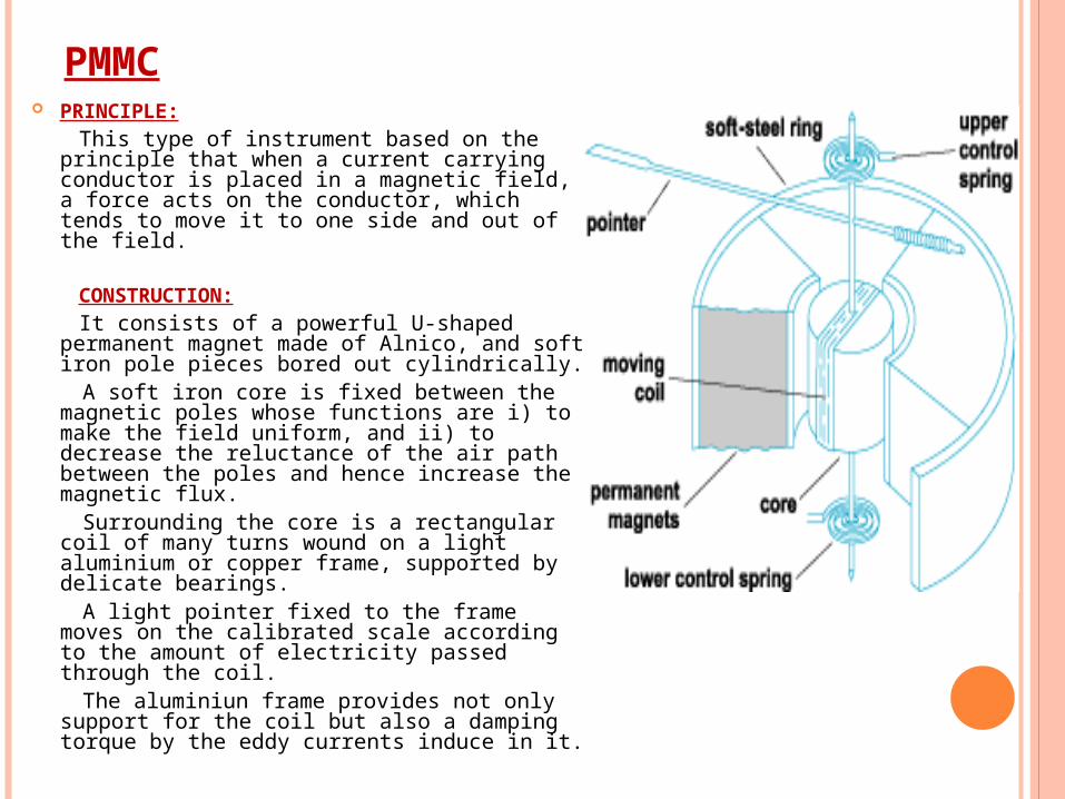
PMMC PRINCIPLE: This type of instrument based on the
principle that when a current carrying conductor is placed in a magnetic field, a force acts on the conductor, which tends to move it to one side and out of the field.
CONSTRUCTION: It consists of a powerful U-shaped
permanent magnet made of Alnico, and soft iron pole pieces bored out cylindrically.
A soft iron core is fixed between the magnetic poles whose functions are i) to make the field uniform, and ii) to decrease the reluctance of the air path between the poles and hence increase the magnetic flux.
Surrounding the core is a rectangular coil of many turns wound on a light aluminium or copper frame, supported by delicate bearings.
A light pointer fixed to the frame moves on the calibrated scale according to the amount of electricity passed through the coil.
The aluminiun frame provides not only support for the coil but also a damping torque by the eddy currents induce in it.
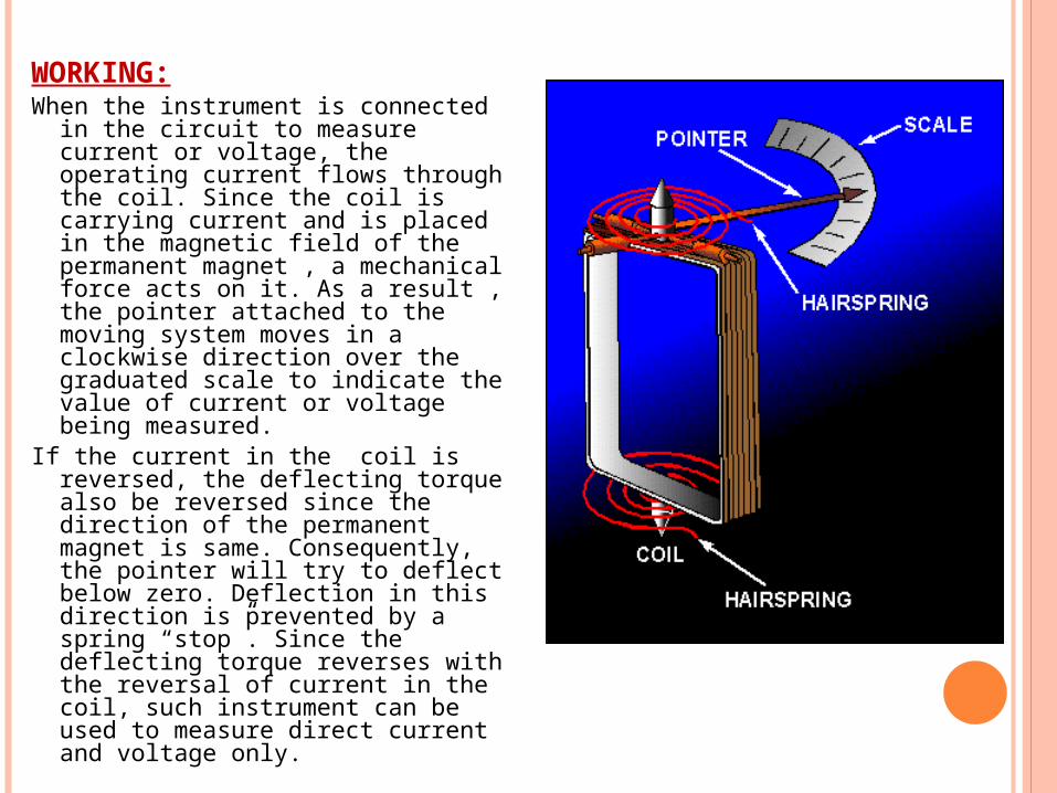
WORKING:When the instrument is connected in
the circuit to measure current or voltage, the operating current flows through the coil. Since the coil is carrying current and is placed in the magnetic field of the permanent magnet , a mechanical force acts on it. As a result , the pointer attached to the moving system moves in a clockwise direction over the graduated scale to indicate the value of current or voltage being measured.
If the current in the coil is reversed, the deflecting torque also be reversed since the direction of the permanent magnet is same. Consequently, the pointer will try to deflect below zero. Deflection in this direction is prevented by a spring “stop”. Since the deflecting torque reverses with the reversal of current in the coil, such instrument can be used to measure direct current and voltage only.
ADVANTAGE: Low power consumption. Uniform scale extendable over an arc of 270º or so. High torque weight ratio. No hysteresis loss. Very effective and efficient eddy current damping. Not effected much by stray and magnetic fields due to strong operating
field.
DISADVANTAGE: Costlier compared to moving iron instruments, due to delicate
construction and accurate machining and assembly of various parts. Some error arise due to the ageing of control springs and the
permanent magnet. Use limited to d.c. only. Scale length of meter can be increased from 120º and 240º or even
270º or 300º.
APPLICATION: PMMC instruments can be used as dc ammeter. And its range can be
increased by using a large number of turns in parallel with the instrument.
The range of this instrument, when used as a dc voltmeter, can be increased by using a high resistance in series with it.
MOVING IRON INSTRUMENTS
Moving Iron instruments depend for their action upon the magnetic effect of current, and are widely used as indicating instruments. In this type of instrument , the coil is stationery and the deflection is caused by a soft-iron piece moving in the field produced by the coil.
There are two types of moving iron instruments:i) Attraction typeii) Repulsion type
Attraction type:
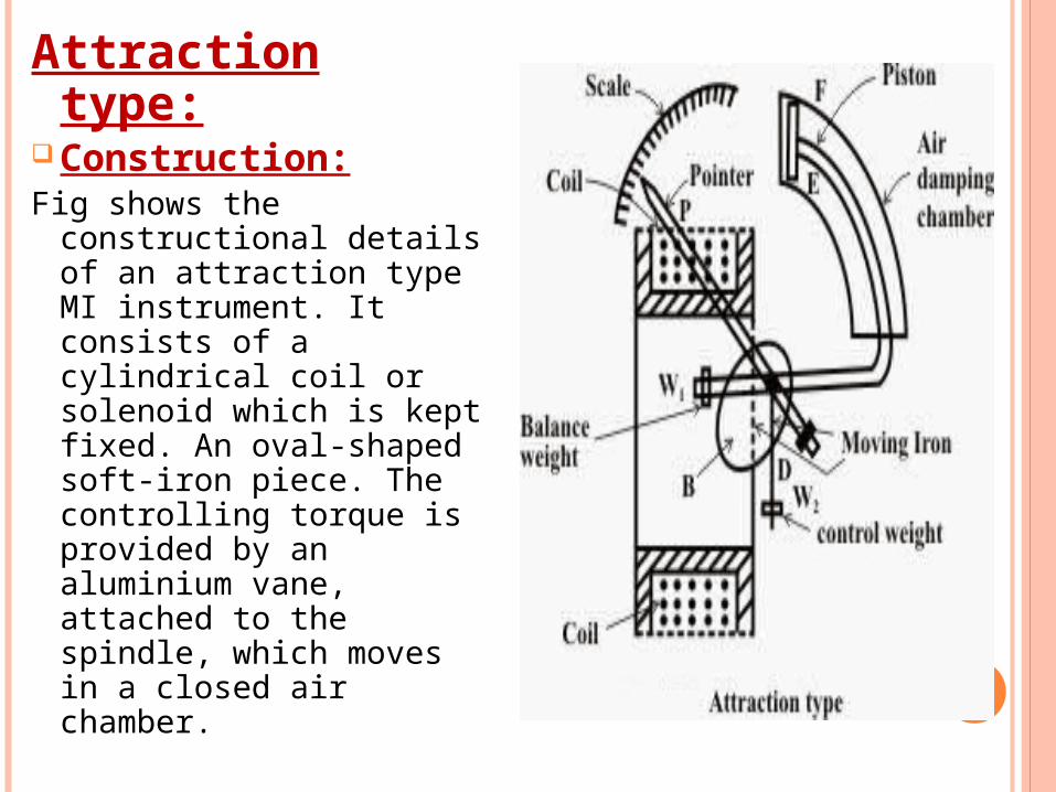
Construction:Fig shows the
constructional details of an attraction type MI instrument. It consists of a cylindrical coil or solenoid which is kept fixed. An oval-shaped soft-iron piece. The controlling torque is provided by an aluminium vane, attached to the spindle, which moves in a closed air chamber.
Working:When the instrument is connected in the circuit to
measure current or voltage, the operating current flowing through the coil sets up a magnetic field. In other words, the coil behaves like a magnet and therefore it attracts the soft iron piece towards it. The result is that the pointer attached to the moving system moves from zero position. The pointer will come to rest at a position where deflecting torque is equal to the controlling torque. If current in the coil is reversed, the direction of magnetic field also reverses and so does the magnetism produce in the soft iron piece. Hence, the direction of the deflecting torque remains unchanged. For this reason, such instruments can be used for both d.c. and a.c. measurements.
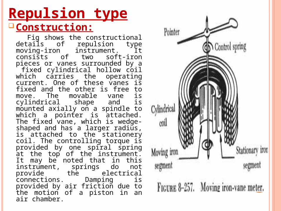
Repulsion typeConstruction: Fig shows the constructional
details of repulsion type moving-iron instrument. It consists of two soft-iron pieces or vanes surrounded by a fixed cylindrical hollow coil which carries the operating current. One of these vanes is fixed and the other is free to move. The movable vane is cylindrical shape and is mounted axially on a spindle to which a pointer is attached. The fixed vane, which is wedge-shaped and has a larger radius, is attached to the stationery coil. The controlling torque is provided by one spiral spring at the top of the instrument. It may be noted that in this instrument, springs do not provide the electrical connections. Damping is provided by air friction due to the motion of a piston in an air chamber.
Working: When current to be measured or current proportional to
the voltage to be measured flows through the coil, a magnetic field is set up by the coil. This magnetic field magnetises the two vanes in the same direction i.e. similar polarities are developed at the same ends of the vanes. Since the adjacent edges of the vanes are of the same polarity, the two vanes repel each other. As the fixed vane cannot move, the movable vane deflects and causes the pointer to move from zero position. The pointer will come to rest at a position where deflecting torque is equal to controlling torque provided by the spring. If the current in the coil is reversed, the direction of deflection remains unchanged. It is because reversal of the field of the coil reverses the magnetisation of both iron vanes so that they repel each other regardless which way current flows through the coil. For this reason, such instruments can be used for both d.c. and a.c. applications.
o Advantages:i) Cheap, robust and give reliable service.
ii) Usable in both a.c. and d.c. circuits.o Disadvantages:i) Have non-linear scale.
ii) Cannot be calibrate with high degree of precision for d.c. on account of the affect of hysteresis in the iron vanes.
iii)Deflection up to 240º only may be obtained with this instrument.
iv)This instrument will always have to be put in the vertical position if it uses gravity control.
o Errors with MI instruments:i) Due to hysteresis when used in a.c. and d.c.
ii) Due to stray magnetic fields when used both in a.c. and d.c.
iii)Due to frequency variation when used in a.c.
iv)Due to waveforms effect when used in a.c.
Applications of MI instruments:As an ammeter:It may be constructed for full-scale deflection of 0.1
to 30A with out the use of shunts or current transformers. To obtain full-scale deflection with currents less than 0.1A, it requires a coil with a large number of fine wire turns, which results in an ammeter with a high impedance.
As an voltmeter:The MI voltmeter is a fairly low impedance
instrument, typically, 50Ω/V for a 100V instrument. The lowest full scale is of the order of 50V.The range of the instrument, when used as a voltmeter, can be extended by using a high non-inductive resistance R connected in series with it. This series resistance is known as ‘multiplier’.
ELECTRODYNAMOMETER
TYPE INSTRUMENT
It works on dynamometer principle i.e. mechanical force exists between two current carrying conductors or coils.
Similar to PMMC Portable, highest precision. Transfer instruments.
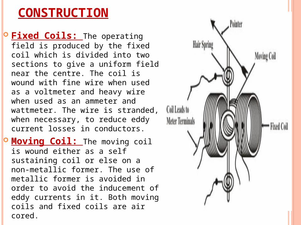
CONSTRUCTION
Fixed Coils: The operating field is produced by the fixed coil which is divided into two sections to give a uniform field near the centre. The coil is wound with fine wire when used as a voltmeter and heavy wire when used as an ammeter and wattmeter. The wire is stranded, when necessary, to reduce eddy current losses in conductors.
Moving Coil: The moving coil is wound either as a self sustaining coil or else on a non-metallic former. The use of metallic former is avoided in order to avoid the inducement of eddy currents in it. Both moving coils and fixed coils are air cored.
Moving System: The moving coil is supported by an aluminium spindle and jewel bearings and carries a pointer moving over a graduated scale. The entire movement is very solid and rigidly constructed in order to keep mechanical dimensions stable and its calibration in tact.
Control system: The controlling torque is provided by two control springs, which also act as leads to the moving coil.
Damping System: Air friction damping is used in these instruments and may be either piston type or vane type. Eddy current damping cannot be used in these instruments as introduction of a permanent magnet for the purpose would distort the working magnetic field of the instrument.
Shielding: The operating magnetic field produced by the fixed coils in these instruments is somewhat weaker (0.005-0.006T) in comparison to that in instruments of other types. So it is essential to provide magnetic shielding to this arrangement.
The complete assembly is surrounded by a laminated steel shield to protect the instrument from external magnetic field which may affect the operation of the instrument.
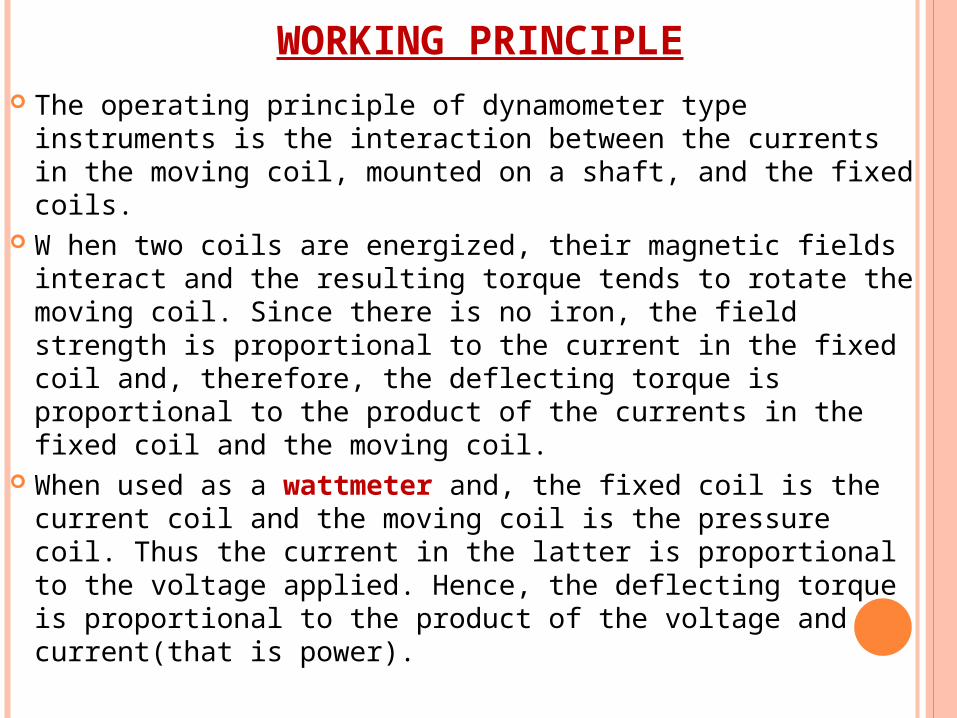
WORKING PRINCIPLE The operating principle of dynamometer type instruments
is the interaction between the currents in the moving coil, mounted on a shaft, and the fixed coils.
W hen two coils are energized, their magnetic fields interact and the resulting torque tends to rotate the moving coil. Since there is no iron, the field strength is proportional to the current in the fixed coil and, therefore, the deflecting torque is proportional to the product of the currents in the fixed coil and the moving coil.
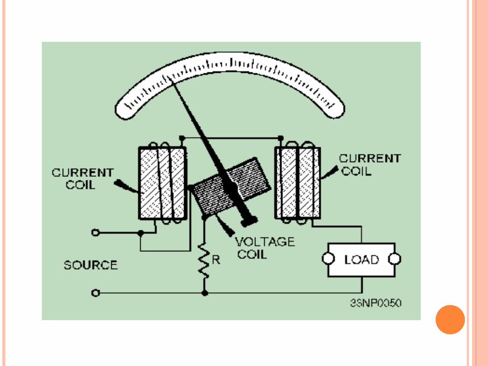
When used as a wattmeter and, the fixed coil is the current coil and the moving coil is the pressure coil. Thus the current in the latter is proportional to the voltage applied. Hence, the deflecting torque is proportional to the product of the voltage and current(that is power).
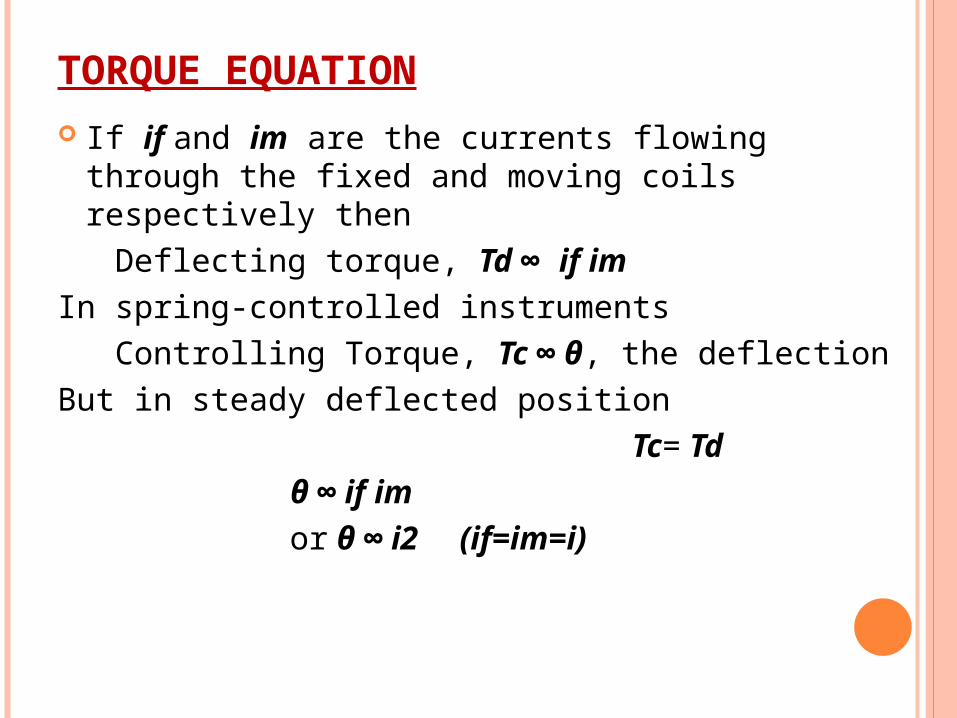
TORQUE EQUATION If if and im are the currents flowing through the
fixed and moving coils respectively then Deflecting torque, Td ∞ if imIn spring-controlled instruments Controlling Torque, Tc ∞ θ, the deflectionBut in steady deflected position Tc= Td θ ∞ if im or θ ∞ i2 (if=im=i)
ERRORS
Frictional Error: Due to Heavy moving parts. Temperature Error: Temperature errors due to
internal heating. Error due to stray magnetic fields Frequency Error:
MERITS As the instrument has square-law response, so
can be used on both dc as well as on ac. These instruments are free from hysteresis and
eddy current errors because of absence of iron in the operating parts of the instrument.
Ammeters up to 10A and voltmeters up to 600V can be constructed with precision grade accuracy.
Dynamometer type voltmeters are very useful for accurate measurement of rms values of voltages irrespective of waveforms.
Because of precision grade accuracy and same calibration for dc and ac measurements these instruments are used as transfer and calibration instruments.
DEMERITS The scale is not uniform as the instrument
has square-law response. The magnetic field strength obtained in these
instruments, being small due to the absence of iron, a large number of ampere turns are required on the moving coil in order to obtain the necessary deflecting torque. As a result, the moving system becomes heavy and power loss becomes high.
Small torque-weight ratio. High frictional losses. Low sensitivity. Expensive.

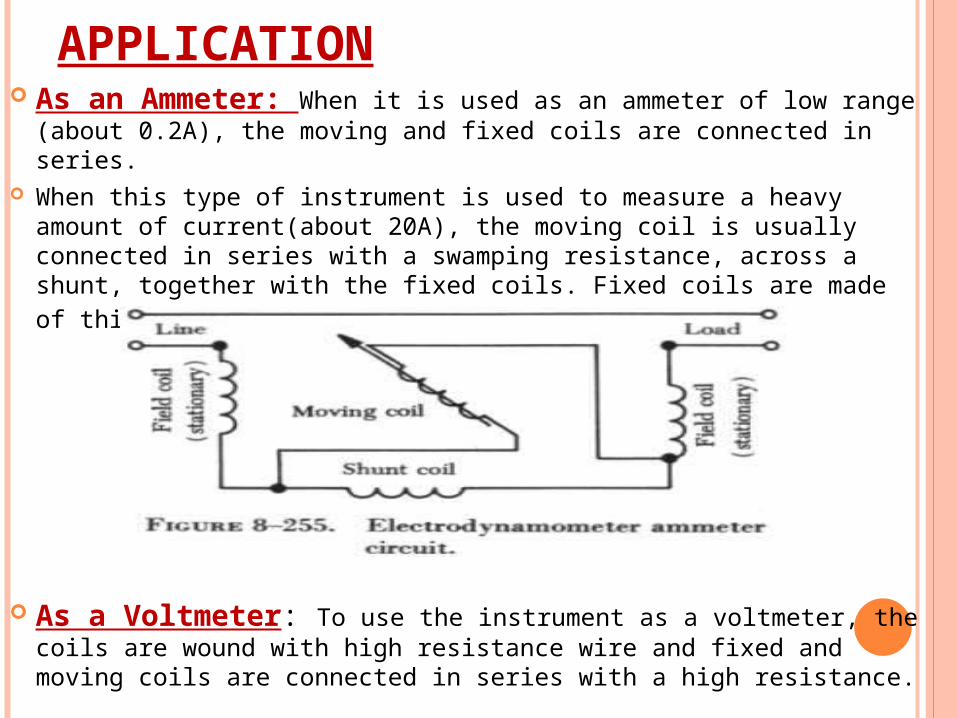
APPLICATION As an Ammeter: When it is used as an ammeter of low range
(about 0.2A), the moving and fixed coils are connected in series. When this type of instrument is used to measure a heavy amount
of current(about 20A), the moving coil is usually connected in series with a swamping resistance, across a shunt, together with the fixed coils. Fixed coils are made of thick wires to carry larger currents.
As a Voltmeter: To use the instrument as a voltmeter, the coils are wound with high resistance wire and fixed and moving coils are connected in series with a high resistance.


