Earth-Rite II RTR Static Earthing System For 12/24 Volt DC Supplies Installation & Operating Instructions READ MANUAL BEFORE COMMENCING WITH INSTALLATION II 2 (1) GD Model: ERII - June 11 The safety of any system incorporating the equipment referred to in this manual is the responsibility of the installer of the system. If the equipment is used in a manner not specified by the manufacturer, the protection provided by the equipment may be impaired. Any warranty is made void if the equipment is not installed, or used, in accordance with the manufacturers instructions. ® www.newson-gale.co.uk EN
Transcript
Earth-Rite II RTR Static Earthing System
For 12/24 Volt DC Supplies
Installation & Operating Instructions
READ MANUALBEFORE COMMENCINGWITH INSTALLATION
II 2 (1) GD
Model: ERII - June 11
The safety of any system incorporating the equipment referred to in this manual is the responsibility of the installer of the system.
If the equipment is used in a manner not specified by the manufacturer, the protection provided by the equipment may be impaired.
Any warranty is made void if the equipment is not installed, or used, in accordance with the manufacturers instructions.
®
www.newson-gale.co.uk
EN
The lid of the Monitoring Unit enclosure is removed by rotating it in an anti-clockwise direction. A pair of tools, which locate in the two holes in the lid, are provided to assist in this operation.
After installation of wiring, secure the cover to the body making sure it is tight.
The system should be connected as per the enclosed installation drawings.
The Earth-Rite II RTR is a Tri-Mode system (capacitive / resistive monitoring), it is intended for use with Road Tankers. It is set to show permissive only when the system detects the presence of a road tanker and when the connection to earth is less than 10 Ohms nominal resistance. Until this condition is achieved, the system remains non-permissive.
Tri-Mode
System using an Exd IIC Control Unit
A device known as the RTR Tester is available to allow the Earth-Rite II RTR to switch to permissive for test purposes when a road tanker is not present.
The Earth-Rite II RTR system operates using “Tri-Mode” technology which uses the electrical capacitance of the road tanker to ensure the presence of an affective Static Earth Point to which the road tanker is connected. It also monitors that the clamp is connected to a road tanker rather than directly to earthed structures or isolated items of metal. Once permissive, the system continues to monitor the resistive loop circuit from tanker to the Static Earth Point.
Installation
The glands should be fitted in such a way as to maintain the ingress protection rating of the enclosure.
The installation shall be carried out by suitably trained personnel in accordance with the relevant sections of IEC 60079 and EN 60079.
All cables entering the monitoring unit must be connected through approved cable glands in accordance with EN 60079-14 .
The Earth-Rite II system should be powered from 12 or 24 Volts DC.
Earth-Rite IIStatic EarthMonitoring System
Terminology used in this manual
The system should be protected using a 2A fast blow fuse mounted in the distribution board / fuse box.
The monitoring unit should be mounted, with the indicator window facing away from direct sunlight, at a convenient location, visible to the operator.
For correct operation, the cable between the Junction Box (or Cable Reel) and the Monitoring Unit must not exceed 3m in length. If the cable is to be less than 3m in length, an approved barrier (compound-filled) gland shall be used. Refer to the latest edition of IEC 60079-14 or EN 60079-14 for more information.
Note: It is recommended that the transfer operation is interlocked with the contacts of the Earth-Rite II unit. This will ensure that the operation is stopped if the earth connection is inadvertently lost.
Maintenance: Periodically check exterior of enclosure for damage.
RTR Tester
A device known as the RTR Tester is available to allow the Earth-Rite II RTR to switch to permissive for test purposes when a road tanker is not present.
IF YOU ARE IN ANY QUERIES REGARDING THE ABOVE POINTS THEN PLEASE CONTACT NEWSON GALE, OR THEIR APPROVED DISTRIBUTOR, WITHOUT DELAY
The Earth-Rite II has been given a SIL (Safety Integrity Level) rating of 2.
Conformity has been proven to BS EN 61000-6-3 andBS EN 61000-6-2.
The Earth-Rite II has been tested and shown conformity to European Directive 2004/108/EC, and FCC Part 15 Emissions.
Functional Safety
Other Approvals
Electromagnetic Compatibility
Cables from ERII Unit to Site Static Earthing Point
The switch allows the ERII system to be used for grounding both road tanker and other items of plant.
Cable Glands
This cable should be 5mm to 7.5mm OD to accommodate the interference suppression ferrite bead.
Please refer to the latest edition of IEC 60079-14 or EN 60079-14 for more information on suitable cable glands and acceptable cable lengths.
21.0mm 2 core cable (do not use a screened cable or metal armoured cable).
Cable from ERII Unit to optional Mode SelectorKey Switch
NOTE: Cables must be secured close to the enclosure in order to prevent them being accidentally pulled out.
21.0mm 2 core cable (IS circuit). Length: 3m or more.
Unused entries must be fitted with approved stopper plugs.
The metal enclosure of the Earth-Rite II system must be connected to an electrical ground.
IF YOU ARE IN ANY DOUBT REGARDING THE INSTALLATION THEN PLEASE CONTACT NEWSON GALE, OR THEIR APPROVED DISTRIBUTOR, WITHOUT DELAY.
Cable from Supply to the ERII Unit
The ferrite bead should be fitted to the cable as close to the monitoring unit as possible.
24mm single core cable with green sheath.
Optional Mode Selector Key Switch
Key Switch Positions
In the normal OFF position (with key removed) the system is designed to operate with road tankers only. This is the safest option for road tankers as it monitors the capacitance and resistance of the road tanker with respect to ground.
In the ON position (with key held in the switch unit) the system is designed to operate with any item of conductive metal plant, e.g. railcars, drums and IBCs, and other items of low conductivity plant (<10 ohms).
This option monitors the resistance of the plant item with respect to the site static bonding bar / tape.
In the normal quiescent state, with clamp stowed on the insulated pin, the Red Negative Ground Connection LED will show.
Attach the earthing clamp onto the tanker, at a suitable position, and ensure that both of the pointed contacts are positively located.
If the connection is healthy then the Green Positive Ground Connection LEDs will flash and the interlock contacts will close.
The product transfer operation can now take place.
RTR (TRI-MODE) Operation
On completion the earthing clamp should be removed from the tanker and stowed on the insulated pin on the front of the junction box. The Red Negative Ground Connection LED will show.
Important Note - The earthing clamp should be fitted prior to any other operation as per the recommendations of IEC TS 60079-32-1, CLC/TR: 60079-32-1, NFPA 77 and API RP 2003. It is important that the clamp is fitted before hoses are connected to the road tanker and before articulated trailer legs are deployed.
If the earth connection is broken during the transfer / mixing operation then the Red Negative Ground Connection LED will show and the interlock contacts will open.
Cable from ERII Monitoring Unit to ERII Junction Box21.0mm 2 core Cable with blue sheath or identifier
(IS Circuit). Length: Please refer to page 2.
Cable from ERII Unit to Pump Starter21.0mm 2 core cable (for DC Pump Starter)21.0mm 2 core + PE cable (for AC Pump Starter)
Certification Label Detail
This label is fitted behind the window of the Earth-Rite II Exd enclosure
Newson Gale LtdNottingham NG4 2JX UK
Sira 09ATEX2047
II 2 (1) GD0518
DO NOT OPEN WHEN AN EXPLOSIVE GASAND/OR DUST ATMOSPHERE MAY BE PRESENT
Earth-Rite II
Um = vvvvv
Model Number mmmmm
Serial Number: YY/XXXXX
Ex d[ia] IIC T6 Gb(Ga)Ex tb IIIC T80°C IP66 Db
Ta = -40°C to +55°CIECEx SIR 09.0018
www.newson-gale.co.ukwww.newson-gale.co.uk
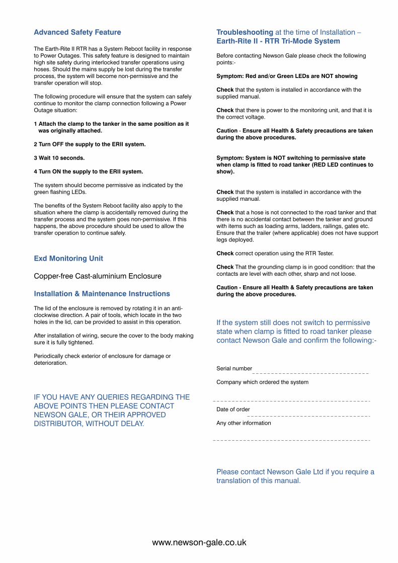
The Earth-Rite II RTR has a System Reboot facility in response to Power Outages. This safety feature is designed to maintain high site safety during interlocked transfer operations using hoses. Should the mains supply be lost during the transfer process, the system will become non-permissive and the transfer operation will stop.
Advanced Safety Feature
1 Attach the clamp to the tanker in the same position as it was originally attached.
The following procedure will ensure that the system can safely continue to monitor the clamp connection following a Power Outage situation:
2 Turn OFF the supply to the ERII system.
3 Wait 10 seconds.
4 Turn ON the supply to the ERII system.
The system should become permissive as indicated by the green flashing LEDs.
The benefits of the System Reboot facility also apply to the situation where the clamp is accidentally removed during the transfer process and the system goes non-permissive. If this happens, the above procedure should be used to allow the transfer operation to continue safely.
Exd Monitoring Unit
Copper-free Cast-aluminium Enclosure
Installation & Maintenance Instructions
After installation of wiring, secure the cover to the body making sure it is fully tightened.
The lid of the enclosure is removed by rotating it in an anti-clockwise direction. A pair of tools, which locate in the two holes in the lid, can be provided to assist in this operation.
Periodically check exterior of enclosure for damage or deterioration.
Troubleshooting at the time of Installation – Earth-Rite II - RTR Tri-Mode System
Check that the system is installed in accordance with the supplied manual.
Check that the system is installed in accordance with the supplied manual.
If the system still does not switch to permissive state when clamp is fitted to road tanker please contact Newson Gale and confirm the following:-
Before contacting Newson Gale please check the following points:-
IF YOU HAVE ANY QUERIES REGARDING THE ABOVE POINTS THEN PLEASE CONTACT NEWSON GALE, OR THEIR APPROVED DISTRIBUTOR, WITHOUT DELAY.
Symptom: Red and/or Green LEDs are NOT showing
Check that there is power to the monitoring unit, and that it is the correct voltage.
Caution - Ensure all Health & Safety precautions are taken during the above procedures.
Symptom: System is NOT switching to permissive state when clamp is fitted to road tanker (RED LED continues to show).
Check that a hose is not connected to the road tanker and that there is no accidental contact between the tanker and ground with items such as loading arms, ladders, railings, gates etc. Ensure that the trailer (where applicable) does not have support legs deployed.
Check correct operation using the RTR Tester.
Caution - Ensure all Health & Safety precautions are taken during the above procedures.
Check That the grounding clamp is in good condition: that the contacts are level with each other, sharp and not loose.
Date of order
Serial number
Company which ordered the system
Any other information
Please contact Newson Gale Ltd if you require a translation of this manual.
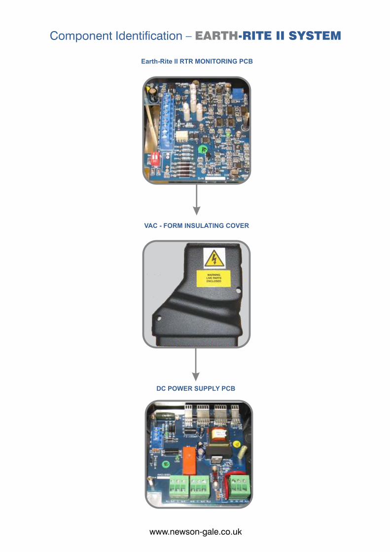
Earth-Rite II RTR MONITORING PCB
Component Identification – -RITE II SYSTEMEARTH
VAC - FORM INSULATING COVER
DC POWER SUPPLY PCB
www.newson-gale.co.ukwww.newson-gale.co.uk
The Earth-Rite II RTR has a System Reboot facility in response to Power Outages. This safety feature is designed to maintain high site safety during interlocked transfer operations using hoses. Should the mains supply be lost during the transfer process, the system will become non-permissive and the transfer operation will stop.
Advanced Safety Feature
1 Attach the clamp to the tanker in the same position as it was originally attached.
The following procedure will ensure that the system can safely continue to monitor the clamp connection following a Power Outage situation:
2 Turn OFF the supply to the ERII system.
3 Wait 10 seconds.
4 Turn ON the supply to the ERII system.
The system should become permissive as indicated by the green flashing LEDs.
The benefits of the System Reboot facility also apply to the situation where the clamp is accidentally removed during the transfer process and the system goes non-permissive. If this happens, the above procedure should be used to allow the transfer operation to continue safely.
Exd Monitoring Unit
Copper-free Cast-aluminium Enclosure
Installation & Maintenance Instructions
After installation of wiring, secure the cover to the body making sure it is fully tightened.
The lid of the enclosure is removed by rotating it in an anti-clockwise direction. A pair of tools, which locate in the two holes in the lid, can be provided to assist in this operation.
Periodically check exterior of enclosure for damage or deterioration.
Troubleshooting at the time of Installation – Earth-Rite II - RTR Tri-Mode System
Check that the system is installed in accordance with the supplied manual.
Check that the system is installed in accordance with the supplied manual.
If the system still does not switch to permissive state when clamp is fitted to road tanker please contact Newson Gale and confirm the following:-
Before contacting Newson Gale please check the following points:-
IF YOU HAVE ANY QUERIES REGARDING THE ABOVE POINTS THEN PLEASE CONTACT NEWSON GALE, OR THEIR APPROVED DISTRIBUTOR, WITHOUT DELAY.
Symptom: Red and/or Green LEDs are NOT showing
Check that there is power to the monitoring unit, and that it is the correct voltage.
Caution - Ensure all Health & Safety precautions are taken during the above procedures.
Symptom: System is NOT switching to permissive state when clamp is fitted to road tanker (RED LED continues to show).
Check that a hose is not connected to the road tanker and that there is no accidental contact between the tanker and ground with items such as loading arms, ladders, railings, gates etc. Ensure that the trailer (where applicable) does not have support legs deployed.
Check correct operation using the RTR Tester.
Caution - Ensure all Health & Safety precautions are taken during the above procedures.
Check That the grounding clamp is in good condition: that the contacts are level with each other, sharp and not loose.
Date of order
Serial number
Company which ordered the system
Any other information
Please contact Newson Gale Ltd if you require a translation of this manual.
Earth-Rite II RTR MONITORING PCB
Component Identification – -RITE II SYSTEMEARTH
VAC - FORM INSULATING COVER
DC POWER SUPPLY PCB
www.newson-gale.co.ukwww.newson-gale.co.uk
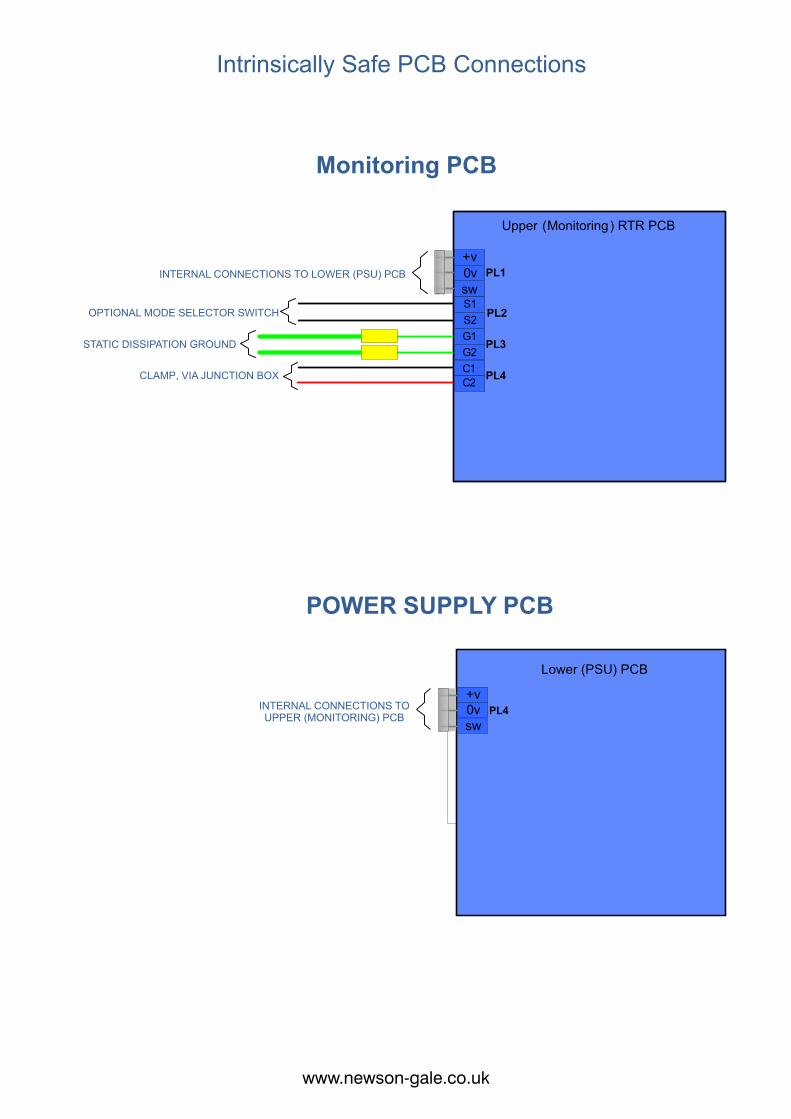
ncDC0
DC+PL1 PL2
PL3
no no ncc cDC0
ncDC0
DC+PL1 PL2
PL3
no no ncc cDC0
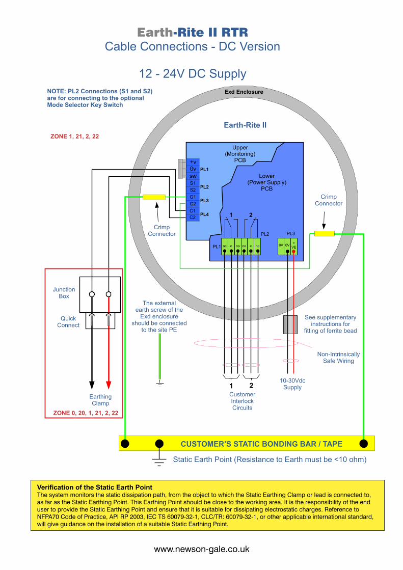
Earth-Rite II RTRCable Connections - DC Version
12 - 24V DC Supply
nc
1 2
2
PL3
1
+vPL1
PL4
PL1
PL2
no no ncc c
G1
C1
0vsw
G2
C2
0V +VE
PL3
0V
S1S2 PL2
NOTE: PL2 Connections (S1 and S2) are for connecting to the optional Mode Selector Key Switch
Upper (Monitoring)
PCB
Lower(Power Supply)
PCB
CrimpConnector
JunctionBox
QuickConnect
EarthingClamp
The externalearth screw of the
Exd enclosure should be connected
to the site PE
See supplementaryinstructions for
fitting of ferrite bead
CrimpConnector
Earth-Rite II
Exd Enclosure
Non-Intrinsically Safe Wiring
CustomerInterlockCircuits
10-30VdcSupply
CUSTOMER’S STATIC BONDING BAR / TAPE
Static Earth Point (Resistance to Earth must be <10 ohm)
Ferrite Bead Fitting Instructionsfor -Rite II Metal DC Systems Earth
CABLE METHOD
DO NOT USE SCREENED ORMETAL ARMOURED CABLE
CONDUIT METHOD
Earth-Rite II Enclosure
Lower (PSU) PCB
Lower (PSU) PCB
Earth-Rite II Enclosure
The Ferrite Bead should be fitted to the cable at a distance of less than 50mm from the enclosure. It should be secured with a cable-tie as shown.
The Ferrite Bead should be fitted just inside the conduit and secured with a cable-tie as shown.
10-30VdcSupplyCable
10-30VdcSupply Wires
in Conduit
ZONE 0, 20, 1, 21, 2, 22
ZONE 1, 21, 2, 22
www.newson-gale.co.ukwww.newson-gale.co.uk
Verification of the Static Earth PointThe system monitors the static dissipation path, from the object to which the Static Earthing Clamp or lead is connected to, as far as the Static Earthing Point. This Earthing Point should be close to the working area. It is the responsibility of the end user to provide the Static Earthing Point and ensure that it is suitable for dissipating electrostatic charges. Reference to NFPA70 Code of Practice, API RP 2003, IEC TS 60079-32-1, CLC/TR: 60079-32-1, or other applicable international standard, will give guidance on the installation of a suitable Static Earthing Point.
ncDC0
DC+PL1 PL2
PL3
no no ncc cDC0
ncDC0
DC+PL1 PL2
PL3
no no ncc cDC0
Earth-Rite II RTRCable Connections - DC Version
12 - 24V DC Supply
nc
1 2
2
PL3
1
+vPL1
PL4
PL1
PL2
no no ncc c
G1
C1
0vsw
G2
C2
0V +VE
PL3
0V
S1S2 PL2
NOTE: PL2 Connections (S1 and S2) are for connecting to the optional Mode Selector Key Switch
Upper (Monitoring)
PCB
Lower(Power Supply)
PCB
CrimpConnector
JunctionBox
QuickConnect
EarthingClamp
The externalearth screw of the
Exd enclosure should be connected
to the site PE
See supplementaryinstructions for
fitting of ferrite bead
CrimpConnector
Earth-Rite II
Exd Enclosure
Non-Intrinsically Safe Wiring
CustomerInterlockCircuits
10-30VdcSupply
CUSTOMER’S STATIC BONDING BAR / TAPE
Static Earth Point (Resistance to Earth must be <10 ohm)
Ferrite Bead Fitting Instructionsfor -Rite II Metal DC Systems Earth
CABLE METHOD
DO NOT USE SCREENED ORMETAL ARMOURED CABLE
CONDUIT METHOD
Earth-Rite II Enclosure
Lower (PSU) PCB
Lower (PSU) PCB
Earth-Rite II Enclosure
The Ferrite Bead should be fitted to the cable at a distance of less than 50mm from the enclosure. It should be secured with a cable-tie as shown.
The Ferrite Bead should be fitted just inside the conduit and secured with a cable-tie as shown.
10-30VdcSupplyCable
10-30VdcSupply Wires
in Conduit
ZONE 0, 20, 1, 21, 2, 22
ZONE 1, 21, 2, 22
www.newson-gale.co.ukwww.newson-gale.co.uk
Verification of the Static Earth PointThe system monitors the static dissipation path, from the object to which the Static Earthing Clamp or lead is connected to, as far as the Static Earthing Point. This Earthing Point should be close to the working area. It is the responsibility of the end user to provide the Static Earthing Point and ensure that it is suitable for dissipating electrostatic charges. Reference to NFPA70 Code of Practice, API RP 2003, IEC TS 60079-32-1, CLC/TR: 60079-32-1, or other applicable international standard, will give guidance on the installation of a suitable Static Earthing Point.
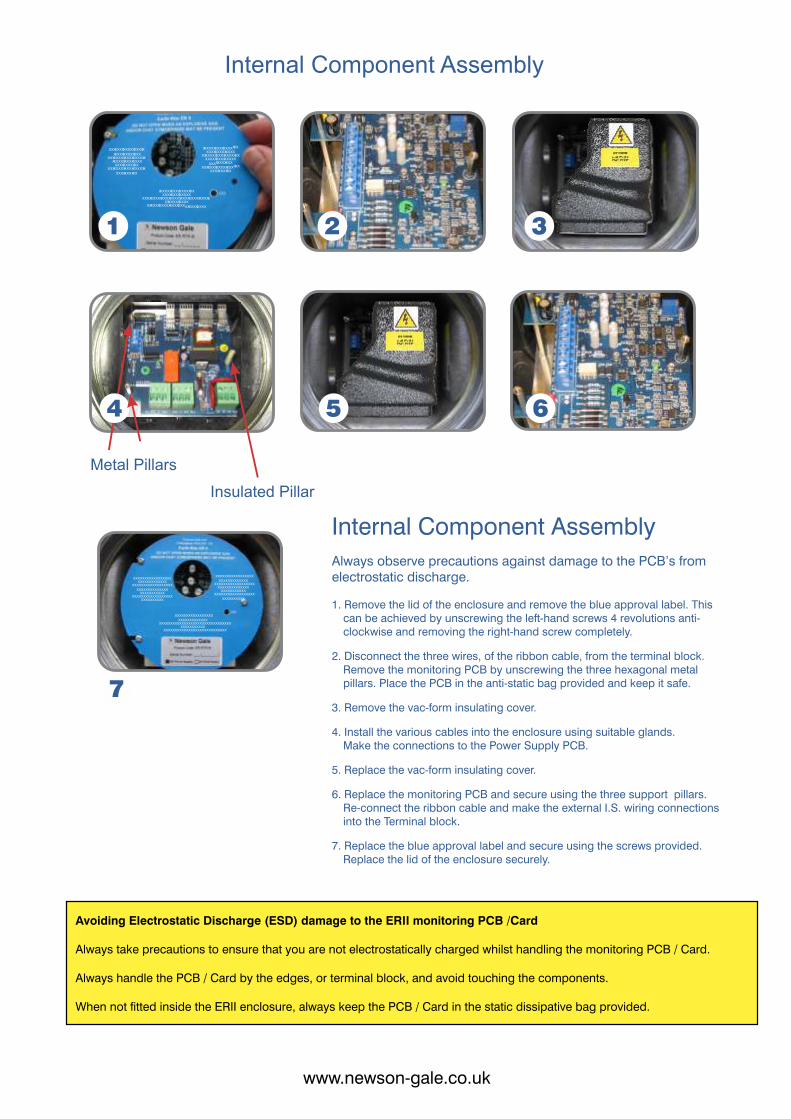
+v0vsw 4. Install the various cables into the enclosure using suitable glands.
Make the connections to the Power Supply PCB.
2. Disconnect the three wires, of the ribbon cable, from the terminal block.Remove the monitoring PCB by unscrewing the three hexagonal metal pillars. Place the PCB in the anti-static bag provided and keep it safe.
1. Remove the lid of the enclosure and remove the blue approval label. This can be achieved by unscrewing the left-hand screws 4 revolutions anti-clockwise and removing the right-hand screw completely.
6. Replace the monitoring PCB and secure using the three support pillars. Re-connect the ribbon cable and make the external I.S. wiring connections into the Terminal block.
Internal Component Assembly
3. Remove the vac-form insulating cover.
5. Replace the vac-form insulating cover.
Always observe precautions against damage to the PCB’s from electrostatic discharge.
7. Replace the blue approval label and secure using the screws provided. Replace the lid of the enclosure securely.
Metal PillarsInsulated Pillar
XXXXXXXXXXXXXXXXXXXXXXXXXXXXXX
XXXXXXXXXXXXXXXXXXXXXXXXXXXXXXXX
XXXXXXXXXXXXXXXXXXXXXXXXXXXXX
XXXXXXXXXX
XXXXXXXXXXXXXXXXXXXXXXXXXXXXXX
XXXXXXXXXXXXXXXXXXXXXXXXXXXXXXXX
XXXXXXXXXXXXXXXXXXXXXXXXXXXXX
XXXXXXXXXX
XXXXXXXXXXXXXXXXXXXXXXXXXXXXXX
XXXXXXXXXXXXXXXXXXXXXXXXXXXXXXXXXXXXXXXXXXX
XXXXXXXXXXXXXXXXXXXXXXXXXXXX
1
5
3
XXXXXXXXXXXXXXXXXXXXXXXXXXXXXX
XXXXXXXXXXXXXXXXXXXXXXXXXXXXXXXX
XXXXXXXXXXXXXXXXXXXXXXXXXXXXX
XXXXXXXXXX
XXXXXXXXXXXXXXXXXXXXXXXXXXXXXX
XXXXXXXXXXXXXXXXXXXXXXXXXXXXXXXX
XXXXXXXXXXXXXXXXXXXXXXXXXXXXX
XXXXXXXXXX
XXXXXXXXXXXXXXXXXXXXXXXXXXXXXX
XXXXXXXXXXXXXXXXXXXXXXXXXXXXXXXXXXXXXXXXXXX
XXXXXXXXXXXXXXXXXXXXXXXXXXXX
7
4
2
6
www.newson-gale.co.ukwww.newson-gale.co.uk
When not fitted inside the ERII enclosure, always keep the PCB / Card in the static dissipative bag provided.
Avoiding Electrostatic Discharge (ESD) damage to the ERII monitoring PCB /Card
Always take precautions to ensure that you are not electrostatically charged whilst handling the monitoring PCB / Card.
Always handle the PCB / Card by the edges, or terminal block, and avoid touching the components.
A. In the normal "rest" state, with the Earthing Clamp
stowed on the insulated pin, the Negative Earth RedCondition LED will be showing.
B. Attach the Earthing Clamp onto the Road Tanker at a
suitable point which is in contact with the tank/frame and ensure that the pointed contacts are positively located.
If the connection to the Road Tanker and Earth is good,
then the Positive Earth Condition LEDs will flash Greenand the interlock contacts will close.
The product transfer operation cannow take place.
D. On completion the Earthing Clamp should be
removed from the road tanker and stowed on the
insulated pin on the front of the junction box. The RedNegative Earth Condition LED will show.
C. If the connection between the Road Tanker and Earth
is broken during the transfer operation, then the
Negative Earth Condition LED will show and the Redinterlock contacts will open.
Operation - RTR Tri-ModeNote: The Earthing Clamp should be fitted prior to fitting hoses, or any other operation.
A. In the normal "rest" state, with the Earthing Clamp
stowed on the insulated pin, the Negative Earth RedCondition LED will be showing.
If the connection to the plant item and Earth is good, then
the Positive Earth Condition LEDs will flash and Greenthe interlock contacts will close.
The product transfer / mixing operation can now take place.
B. Attach the Earthing Clamp onto the conductive plant
item at a suitable point and ensure that the pointed contacts are positively located.
C. If the connection between the plant item and Earth is
broken during the transfer operation, then the
Negative Earth Condition LED will show and the Redinterlock contacts will open.
D. On completion the Earthing Clamp should be
removed from the plant item and stowed on the insulated
pin on the front of the junction box. The Negative RedEarth Condition LED will show.
Note: The Earthing Clamp should be fitted prior to fitting hoses, or any other operation.
OperationWith system switched to Single-Mode using the Mode Selector Key Switch
www.newson-gale.co.ukwww.newson-gale.co.uk
ERIIJunction Box
Clamp
GaleNewson
GaleNewson
ERII Junction Box
Clamp
GaleNewson
GaleNewson
GaleNewson
GaleNewson
GaleNewson
GaleNewson
XERII
Junction Box
Clamp
GaleNewson
GaleNewson
ERII Junction Box
Clamp
GaleNewson
GaleNewson
GaleNewson
GaleNewson
GaleNewson
GaleNewson
X
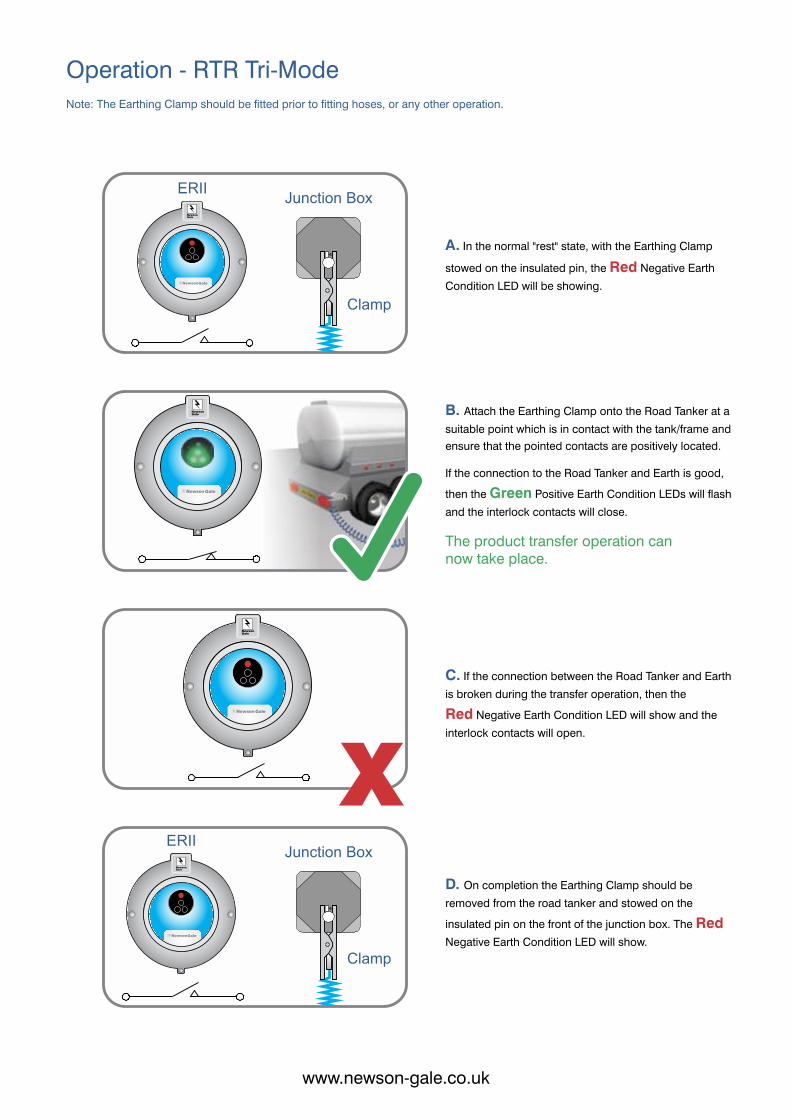
A. In the normal "rest" state, with the Earthing Clamp
stowed on the insulated pin, the Negative Earth RedCondition LED will be showing.
B. Attach the Earthing Clamp onto the Road Tanker at a
suitable point which is in contact with the tank/frame and ensure that the pointed contacts are positively located.
If the connection to the Road Tanker and Earth is good,
then the Positive Earth Condition LEDs will flash Greenand the interlock contacts will close.
The product transfer operation cannow take place.
D. On completion the Earthing Clamp should be
removed from the road tanker and stowed on the
insulated pin on the front of the junction box. The RedNegative Earth Condition LED will show.
C. If the connection between the Road Tanker and Earth
is broken during the transfer operation, then the
Negative Earth Condition LED will show and the Redinterlock contacts will open.
Operation - RTR Tri-ModeNote: The Earthing Clamp should be fitted prior to fitting hoses, or any other operation.
A. In the normal "rest" state, with the Earthing Clamp
stowed on the insulated pin, the Negative Earth RedCondition LED will be showing.
If the connection to the plant item and Earth is good, then
the Positive Earth Condition LEDs will flash and Greenthe interlock contacts will close.
The product transfer / mixing operation can now take place.
B. Attach the Earthing Clamp onto the conductive plant
item at a suitable point and ensure that the pointed contacts are positively located.
C. If the connection between the plant item and Earth is
broken during the transfer operation, then the
Negative Earth Condition LED will show and the Redinterlock contacts will open.
D. On completion the Earthing Clamp should be
removed from the plant item and stowed on the insulated
pin on the front of the junction box. The Negative RedEarth Condition LED will show.
Note: The Earthing Clamp should be fitted prior to fitting hoses, or any other operation.
OperationWith system switched to Single-Mode using the Mode Selector Key Switch
www.newson-gale.co.ukwww.newson-gale.co.uk
ERIIJunction Box
Clamp
GaleNewson
GaleNewson
ERII Junction Box
Clamp
GaleNewson
GaleNewson
GaleNewson
GaleNewson
GaleNewson
GaleNewson
XERII
Junction Box
Clamp
GaleNewson
GaleNewson
ERII Junction Box
Clamp
GaleNewson
GaleNewson
GaleNewson
GaleNewson
GaleNewson
GaleNewson
X
Earth-Rite ERII Dimensions
Ex tb IIIC T80°C IP66 Db Ta = -40°C to +55°C
Construction Copper-free cast-alloy
Monitoring Unit
Output Relay contact rating 2 off voltage free change-over switch contacts,
NB: In line with our policy of continual product development,we reserve the right to alter specifications at any time.
www.newson-gale.co.ukwww.newson-gale.co.uk12 13
Junction Box
B
E
A F
C
FIXING HOLE DIAMETER D
STOWAGE PIN
FIXING HOLES ARE ACCESSIBLE
WHEN THE LIDIS REMOVED
A mm B mm C mm
75 80 57
PRODUCT DESCRIPTION
Junction Box with Stowage Pin
MAIN DIMENSIONS
D mm E mm F mm
4.5 68 45
FIXING DIMENSIONS
192 155 132Exd Earth-Rite II Monitoring Unit 7 140 140
F
Earth-Rite II Exd Monitoring Unit
C
AE
B
FIXING HOLE DIAMETER D
with window
No user adjustment is required.
The equipment contains no user-replaceable parts.
The equipment is not intended to be repaired by the user. Repair of the equipment is to be carried out by the manufacturer, or their approved agents, in accordance with the applicable code of practice.
Instructions for safe selection,installation, use, maintenanceand repair
The equipment may be used in the presence of flammable gases and vapours with apparatus groups IIC or IIB or IIA and with temperature classes T1 or T2 or T3 or T4 or T5 or T6.
Regular periodic inspection of the equipment should be performed by suitably trained personnel in accordance with the applicable code of practice (typically IEC/EN 60079-17) to ensure it is maintained in a satisfactory condition.
The equipment is certified for use in ambient temperatures in o othe range of –40 C to +55 C and should not be used outside
this range.
The equipment is to be installed by suitably trained personnel in accordance with the applicable code of practice (typically IEC/EN 60079-14).
The equipment may be used in zones 1, 2, 21 and 22 with flammable gases and dusts.
The equipment may be used in the presence of flammable dusts, powders and flyings, conductive or non-conductive, the only limitation being the maximum external surface
otemperature of 80 C.
Verification of the Static Earthing Point
The system monitors the static dissipation path, from the object to which the Static Earthing Clamp or lead is connected to, as far as the Static Earthing Point.
It is the responsibility of the end user to provide the Static Earthing Point and ensure that it is suitable for dissipating electrostatic charges. Reference to ATEX 2014/34/EU, ATEX 137, EN 60079-14, IEC TS 60079-32-1, CLC/TR: 60079-32-1, or other equivalent international standard, will give guidance on the installation of a suitable Static Earthing Point.
The above does not apply to any system used to monitor a bond connection only.
IF YOU HAVE ANY QUERIES REGARDING THE ABOVE POINTS THEN PLEASE CONTACT NEWSON GALE WITHOUT DELAY.
Certification Label Detail
User instructions in compliance with
IEC 60079-0:2007 clause 30
The following instructions apply to the Earth-Rite II Earth Monitoring Unit, Ex d[ia], covered by certificate numbers IECEx SIR 09.0018 and Sira 09ATEX2047.
NOTE:vvvvv = UM = 250Vac/dc, Ui = 30Vdcmmmmm = RTRMEDddddd = RTRYY = Year of ManufactureXXXXX = Specific Serial NumberCCCCC = ERII-Q-09239-2 Al
Intrinsically safe output at PL3/PL4 combined:Tri-Mode: Uo = 8.61V, Io = 0.060A, Po = 0.129W, Co = 1.0µF, Lo = 9868µH
Newson Gale LtdNottingham NG4 2JX UK
Sira 09ATEX2047II 2 (1) GDnnnn
DO NOT OPEN WHEN AN EXPLOSIVE GAS AND/OR DUST ATMOSPHERE MAY BE PRESENT
Earth Rite ER II
Ex d[ia] IIC T6 Gb(Ga)Ex tb IIIC T80oC IP66 Db
Ta = -40oC to +55oCIECEx SIR 09.0018
ddddModel Number: mmmmm
Um = vvvvv
Serial Number: YY/XXXXXControl Drg. CCCCCC
www.newson-gale.co.ukwww.newson-gale.co.uk14 15
1 2
3 4
5
ERII
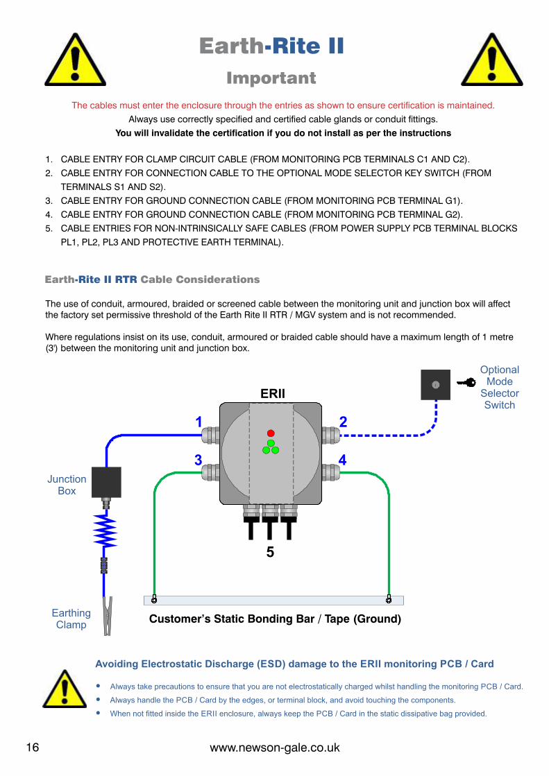
Earth-Rite IIImportant
The cables must enter the enclosure through the entries as shown to ensure certification is maintained.Always use correctly specified and certified cable glands or conduit fittings.
You will invalidate the certification if you do not install as per the instructions
1. CABLE ENTRY FOR CLAMP CIRCUIT CABLE (FROM MONITORING PCB TERMINALS C1 AND C2).2. CABLE ENTRY FOR CONNECTION CABLE TO THE OPTIONAL MODE SELECTOR KEY SWITCH (FROM TERMINALS S1 AND S2).3. CABLE ENTRY FOR GROUND CONNECTION CABLE (FROM MONITORING PCB TERMINAL G1).4. CABLE ENTRY FOR GROUND CONNECTION CABLE (FROM MONITORING PCB TERMINAL G2).5. CABLE ENTRIES FOR NON-INTRINSICALLY SAFE CABLES (FROM POWER SUPPLY PCB TERMINAL BLOCKS PL1, PL2, PL3 AND PROTECTIVE EARTH TERMINAL).
Junction Box
Earthing Clamp
Optional Mode
Selector Switch
Customer’s Static Bonding Bar / Tape (Ground)
Always take precautions to ensure that you are not electrostatically charged whilst handling the monitoring PCB / Card.Ÿ Always handle the PCB / Card by the edges, or terminal block, and avoid touching the components.Ÿ When not fitted inside the ERII enclosure, always keep the PCB / Card in the static dissipative bag provided.Ÿ
Avoiding Electrostatic Discharge (ESD) damage to the ERII monitoring PCB / Card
Where regulations insist on its use, conduit, armoured or braided cable should have a maximum length of 1 metre (3') between the monitoring unit and junction box.
The use of conduit, armoured, braided or screened cable between the monitoring unit and junction box will affect the factory set permissive threshold of the Earth Rite II RTR / MGV system and is not recommended.
Earth Cable Considerations-Rite II RTR
www.newson-gale.co.ukwww.newson-gale.co.uk16 17
Earth ®-Rite II Metal Enclosure Lid Keys
Remove Lid Keys from packaging. Place Lid Keys into the two ERIImetal enclosure lid holes.
With Lid Keys securely located in holes,rotate clockwise to tighten the lid onto
the enclosure.
With Lid Keys securely located in holes,rotate counter-clockwise to loosen the lid
from the enclosure.
1 2
3 4
5
ERII
Earth-Rite IIImportant
The cables must enter the enclosure through the entries as shown to ensure certification is maintained.Always use correctly specified and certified cable glands or conduit fittings.
You will invalidate the certification if you do not install as per the instructions
1. CABLE ENTRY FOR CLAMP CIRCUIT CABLE (FROM MONITORING PCB TERMINALS C1 AND C2).2. CABLE ENTRY FOR CONNECTION CABLE TO THE OPTIONAL MODE SELECTOR KEY SWITCH (FROM TERMINALS S1 AND S2).3. CABLE ENTRY FOR GROUND CONNECTION CABLE (FROM MONITORING PCB TERMINAL G1).4. CABLE ENTRY FOR GROUND CONNECTION CABLE (FROM MONITORING PCB TERMINAL G2).5. CABLE ENTRIES FOR NON-INTRINSICALLY SAFE CABLES (FROM POWER SUPPLY PCB TERMINAL BLOCKS PL1, PL2, PL3 AND PROTECTIVE EARTH TERMINAL).
Junction Box
Earthing Clamp
Optional Mode
Selector Switch
Customer’s Static Bonding Bar / Tape (Ground)
Always take precautions to ensure that you are not electrostatically charged whilst handling the monitoring PCB / Card.Ÿ Always handle the PCB / Card by the edges, or terminal block, and avoid touching the components.Ÿ When not fitted inside the ERII enclosure, always keep the PCB / Card in the static dissipative bag provided.Ÿ
Avoiding Electrostatic Discharge (ESD) damage to the ERII monitoring PCB / Card
Where regulations insist on its use, conduit, armoured or braided cable should have a maximum length of 1 metre (3') between the monitoring unit and junction box.
The use of conduit, armoured, braided or screened cable between the monitoring unit and junction box will affect the factory set permissive threshold of the Earth Rite II RTR / MGV system and is not recommended.
Earth Cable Considerations-Rite II RTR
www.newson-gale.co.ukwww.newson-gale.co.uk16 17
Earth ®-Rite II Metal Enclosure Lid Keys
Remove Lid Keys from packaging. Place Lid Keys into the two ERIImetal enclosure lid holes.
With Lid Keys securely located in holes,rotate clockwise to tighten the lid onto
the enclosure.
With Lid Keys securely located in holes,rotate counter-clockwise to loosen the lid