Journal of Theoretical and Applied Information Technology 10
th March 2016. Vol.85. No.1
© 2005 - 2016 JATIT & LLS. All rights reserved.
ISSN: 1992-8645 www.jatit.org E-ISSN: 1817-3195
50
STATIC STRUCTURE AND DYNAMIC VIEWS OF
PURCHASES PROCESS AND MODELING IT IN ITERATIVE
METHOD BASED ON USE-CASE SCENARIOS
1F. ALAGHBARI,
2N. AKNIN
Information Technology and Modeling Systems Research Group
Computer Science , University Abdelmalek Essaadi, Faculty of Sciences, Tetouan, Morocco
E-mail: [email protected] ,
2 [email protected]
ABSTRACT
Our research comes to supplement the previous researches that have represented business process modeling
languages. The representation performed in this paper is focuses on two most widely used iterative method
based on Use-Case scenarios for purchase processes: static structure and dynamic views. To clarify how to
use this method we applied it in purchase process by some steps. Use-Cases should be kept as simple as
possible. Occasionally, however, we will encounter irreducible complexity and will need to formulate
complex Use-Cases. Rather than trying to capture this complexity with lots of branching and alternative
flows, it is easier, and less error prone, to model the main flows through this branching network as separate
scenarios. The results presented in this paper as some models in UML. In addition, these models that
facilitates the analysis phase of purchase process and make processes clear from perspective of analysts,
managers, employers and also users. On the other hand, the aim in this paper will make the design phase
easier and explained as a future work to complete the design phase of the purchase operations in
implementation and testing phases.
Keywords: Static Structure, Dynamic Views, Scenarios, Use-Case Scenarios, purchase Process, Use-Case
Diagram.
1. INTRODUCTION
An Information system reflects the reality of
business process to static structure and dynamic
activities of organizations. Therefore, the process of
developing an information system begins by
drawing a domain model of the business as part of
the real world, the result is a conceptual design that
does not include aspects that depend on
computation, it serves as a way of communication
and a guide for the next design phase. Researchers
have examined and proposed extending the use of
object-oriented languages such as UML at the
conceptual level [1]. (e.g. [2], [3], [4]). The
conceptual domain modeling in the business
environment has been represented by UML, which
is interested with providing a representation of
things and objects” that exist and processes,
activities and procedures that arise in a business
environment. The problem with extending object-
oriented models and languages is that such
languages possess no real-world business or
organizational meaning; i.e., it is unclear what the
constructs of such languages mean in terms of the
business [5]. Most previous scientific research
mentioned modeling business processes, according
to Douraid et. al. [6], focused on the procurement
process within the manufacturing sector; forasmuch
the good control of procurement is crucial as well it
composes an interesting proportion of costs along
the whole chain. Thus, Douraid et. al. proposed a
flexible model representing the procurement
process of a supplier-manufacturer relationship to
reduce this complexity and to make it easier to
simulate. For this, they have chosen as the tool of
modeling the Unified Modeling Language (UML)
to design the systems structure and describe its
behavior. The designed UML diagrams could be
transformed into a simulation model to be run by
way of a specialized simulation environment. And
according to Sabah Al-Fedaghi [7] proposed a
uniform conceptual methodology that integrates
Journal of Theoretical and Applied Information Technology 10
th March 2016. Vol.85. No.1
© 2005 - 2016 JATIT & LLS. All rights reserved.
ISSN: 1992-8645 www.jatit.org E-ISSN: 1817-3195
51
static and dynamic features to provide a foundation
for system design in the next phase of development
and proposed a new approach to the problem of
conceptual representation of functionality in the
field of object oriented software development.
Instead of the class/object-based description of
requirements, the methodology incorporates the
dynamic aspects of the system by adopting the
notion of flow.
This paper proposes a new method for
modeling of static structure and dynamic view
problem in the field of business processes and
modeling it in iterative method based on Use-Case
scenarios and applied it in purchases process as part
of business processes.
I TERATIVE METHODOLOGY
Iterative method is a logical extension of the
Spiral Model, but it’s more stricter and legalization
[8]. These are achievement phases on the
respectively, The method is divided into four main
phases: Inception, Elaboration, Construction and
Transition. Iterative methodology as mentioned in
Rational Unified Process [9], split the problem into
partial problems and solved every problem in
several phases, There is usually a preliminary step,
the inception phase where user requirements are
gathered, a business case for the project is defined,
and ends with testing phase, passing through
analysis and design phase, so that every part takes a
specific time period of the schedule in advance, so
that the issuance is preliminary solution to the
problem, and then move on to the second part of the
main problem, and so on. Typical artifacts from the
inception phase are the initial revisions of the
project’s Vision, Supplementary Specification,
Use-Case Model, and Glossary. These documents
are further refined during the subsequent
development phases. Following the inception phase
is one or more elaboration phases, during which the
development team will analyze, design, implement,
and test a subset of the user requirements. During
this phase, the development team may also perform
deeper analysis on the user requirements that will
be handled during the next phase. Typical artifacts
from this elaboration phases are updates to the
Vision, Supplementary Specification, Use-Case
Model, and Glossary, and new documentation
specific to analysis and design is generated and
refined: the Domain Model, System Sequence
Diagram Specification, Sequence Diagram
Specification, Operation Contract Specification,
and Class Model [10]. In this paper we used
iterative method in the form of Use-Cases
scenarios, in order to reach clear models of static
structure and dynamic views for business processes
and applied this methodology to purchase processes
as explained in the remaining paragraphs.
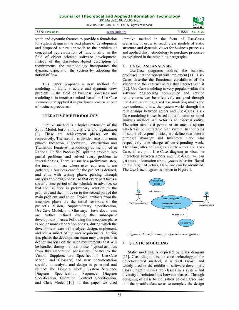
2. U SE-C ASE ANALYSIS
Use-Case diagrams address the business
processes that the system will implement [11]. Use-
Cases describe the functional capabilities of the
system and the external actors that interact with it
[12]. Use-Case modeling is very popular within the
software engineering community and service
requirements can be effectively analyzed through
Use-Case modeling. Use-Case modeling makes the
user understand how the system works through the
relationships between actors and Use-Cases. Use-
Case modeling is user based and a function oriented
analysis method. An Actor is an external entity.
The actor can be a person or an outside system
which will be interactive with system. In the terms
of scope of responsibilities, we define two actors:
purchase manager and Inventory clerk who
respectively take charge of corresponding work.
Therefore, after defining explicitly actors and Use-
Case, if we plot Use-Case diagram to visualize
interaction between actors and Use-Case, we can
get more information about system behavior. Based
on the target of actors, Use-Case can be identified.
The Use-Case diagram is shown in Figure 1.
Figure 1: Use-Case diagram for Need recognition
3. S TATIC MODELING
Static modeling is depicted by class diagram
[13]. Class diagram is the core technology of the
object-oriented method; it is well known and
widely used in the middle of software developers.
Class diagram shows the classes in a system and
diversity of relationships between classes. Through
designing of class to realization of each Use-Case
into the specific class so as to complete the design
Journal of Theoretical and Applied Information Technology 10
th March 2016. Vol.85. No.1
© 2005 - 2016 JATIT & LLS. All rights reserved.
ISSN: 1992-8645 www.jatit.org E-ISSN: 1817-3195
52
of the process of refinement. The analysis of class
is built on the basis of Use-Case [11]. As analyzed
above, we can plot object class diagram of every
module after defining object classes and their
relations, multidimensional and role. The class
diagram of purchases process is shown in Figure 2.
Yet, the class diagram , object diagram or the Use-
Case diagram gives a static vision of the
functionality [14]. For this reason, we have carried
out some dynamic diagrams to show the behavioral
aspects of this mechanism.
Figure 2: static modeling of purchase process by object
diagram.
4. DYNAMIC MODELING
Use-Case and class model belong to the static
models, system dynamic behavior can be described
using UML dynamic modeling. Dynamic model is
used to describe the function of the system [11]. In
the actual application, many diagrams can be used
such as sequence diagram, collaboration diagram,
activity diagram, communication diagram and state
chart diagram; these dynamic modeling diagrams
can describe object behavior and interaction
between objects from different perspectives.
Specifications are generated. For the sake of brevity
of the paper and complication of the system, we
choose purchase process as examples to show the
processes of dynamic modeling.
4.1 Activity Diagram
Activity diagrams describe the dynamic
behavior of a system. The aim to use activity
diagrams is to model the workflow behind the
system being designed. Sequencing of activities can
be controlled by means of conditions [6]. Three
activity diagrams can synchronize their execution
by sending and receiving signals. Activity diagrams
can be subdivided into swim lanes. Each swim lane
represents activities that are performed in a
particular location, department, or by a specific
actor [15]. Fig.3 is an activity diagram explaining
the flow of objects and events in purchase process.
And therefore activity diagram emphasizes the flow
of control among objects and models the functions
of a system [16]. The purchase process activity
diagram is shown in figure 3.
Figure 3: dynamic modeling of purchase
process by activity diagram.
There are three actors in figure 3, each actor has
some activities in purchase process, and the
activities of purchase process include:
1) Inventory clerk verifies of stock level.
Through the audit by the Inventory
Clerk actor, warehouse becomes ready
to receive any goods.
2) If found a lack of inventory in warehouse
,the Inventory Clerk requests an order
and submitted to Purchase Manager.
3) After that, Purchasing Manager decides to
purchase order according to the
company’s policy and also supply and
demand in the market.
4) After taking purchase decision, purchase
Manager works on to place the purchase
Journal of Theoretical and Applied Information Technology 10
th March 2016. Vol.85. No.1
© 2005 - 2016 JATIT & LLS. All rights reserved.
ISSN: 1992-8645 www.jatit.org E-ISSN: 1817-3195
53
order , at the same time he works on to
select the right supplier, according of
information he had at the company, then
sends the request to the supplier.
5) the Supplier works on to receive the order
, fulfill it , place the invoice Based on
order and transport it to company.
6) Thence Inventory Clerk works on to
receive goods, inspecting goods
according to purchase order.
7) If the goods are Matching to specifications
then transfer it to warehouse, if Not
reject the goods and return it to supplier.
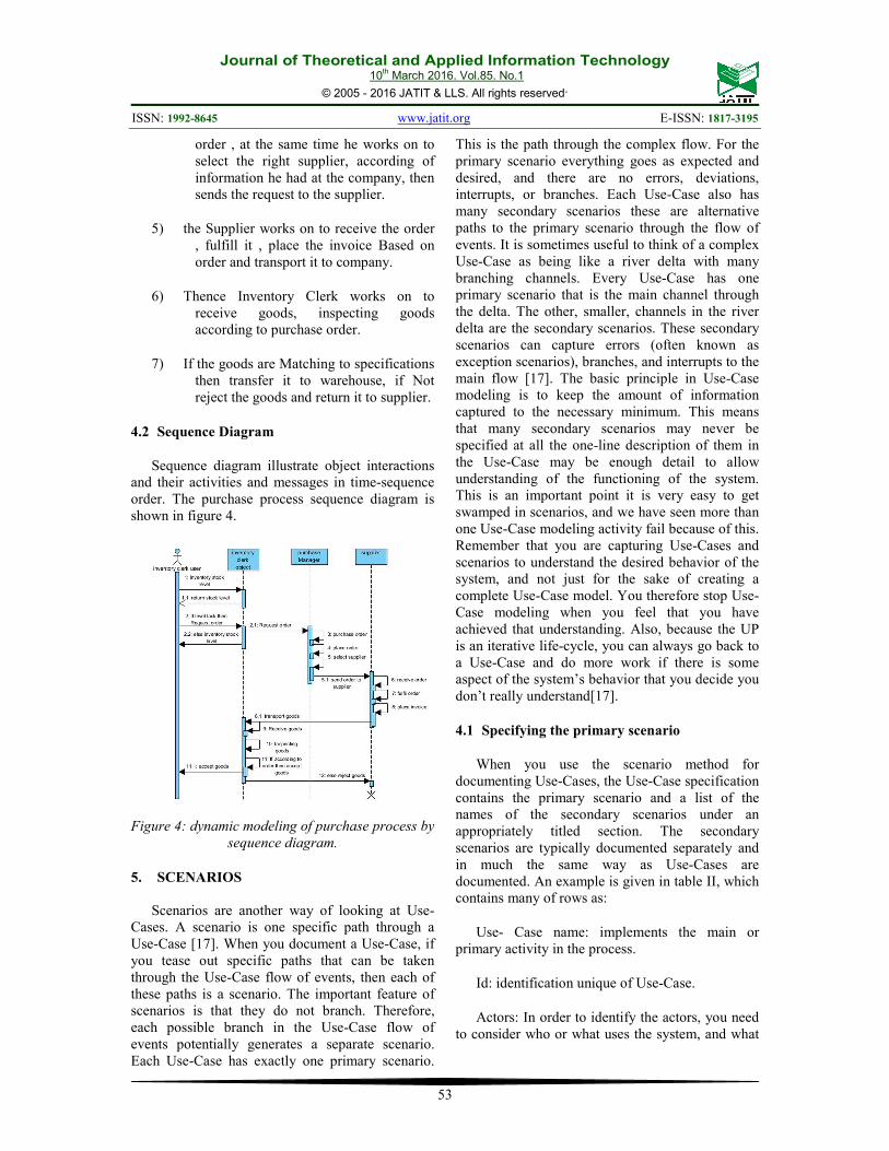
4.2 Sequence Diagram
Sequence diagram illustrate object interactions
and their activities and messages in time-sequence
order. The purchase process sequence diagram is
shown in figure 4.
Figure 4: dynamic modeling of purchase process by
sequence diagram.
5. SCENARIOS
Scenarios are another way of looking at Use-
Cases. A scenario is one specific path through a
Use-Case [17]. When you document a Use-Case, if
you tease out specific paths that can be taken
through the Use-Case flow of events, then each of
these paths is a scenario. The important feature of
scenarios is that they do not branch. Therefore,
each possible branch in the Use-Case flow of
events potentially generates a separate scenario.
Each Use-Case has exactly one primary scenario.
This is the path through the complex flow. For the
primary scenario everything goes as expected and
desired, and there are no errors, deviations,
interrupts, or branches. Each Use-Case also has
many secondary scenarios these are alternative
paths to the primary scenario through the flow of
events. It is sometimes useful to think of a complex
Use-Case as being like a river delta with many
branching channels. Every Use-Case has one
primary scenario that is the main channel through
the delta. The other, smaller, channels in the river
delta are the secondary scenarios. These secondary
scenarios can capture errors (often known as
exception scenarios), branches, and interrupts to the
main flow [17]. The basic principle in Use-Case
modeling is to keep the amount of information
captured to the necessary minimum. This means
that many secondary scenarios may never be
specified at all the one-line description of them in
the Use-Case may be enough detail to allow
understanding of the functioning of the system.
This is an important point it is very easy to get
swamped in scenarios, and we have seen more than
one Use-Case modeling activity fail because of this.
Remember that you are capturing Use-Cases and
scenarios to understand the desired behavior of the
system, and not just for the sake of creating a
complete Use-Case model. You therefore stop Use-
Case modeling when you feel that you have
achieved that understanding. Also, because the UP
is an iterative life-cycle, you can always go back to
a Use-Case and do more work if there is some
aspect of the system’s behavior that you decide you
don’t really understand[17].
4.1 Specifying the primary scenario
When you use the scenario method for
documenting Use-Cases, the Use-Case specification
contains the primary scenario and a list of the
names of the secondary scenarios under an
appropriately titled section. The secondary
scenarios are typically documented separately and
in much the same way as Use-Cases are
documented. An example is given in table II, which
contains many of rows as:
Use- Case name: implements the main or
primary activity in the process.
Id: identification unique of Use-Case.
Actors: In order to identify the actors, you need
to consider who or what uses the system, and what
Journal of Theoretical and Applied Information Technology 10
th March 2016. Vol.85. No.1
© 2005 - 2016 JATIT & LLS. All rights reserved.
ISSN: 1992-8645 www.jatit.org E-ISSN: 1817-3195
54
roles they play in their interactions with Use-Case
[18].
Objects: all objects and classes that interactions
to gathers in the process.
Preconditions: contains some of events or
activities which requires running before do primary
scenario steps.
Primary scenario: contains series of steps as
algorithm in specific Use-Case.
Secondary scenarios: are identified by
inspection of the primary scenarios as possible
alternative flows.
Postconditions: contains some of events or
activities which requires running after do primary
scenario steps. And the rest of details are shown in
table 2.
4.2 Specifying secondary scenarios
You should specify secondary scenarios in the
same way that you specify Use-Cases. You must
always state clearly how the scenario begins and
ensure that it is just one specific path through the
Use-Case flow of events with no branching. Each
secondary scenario must be traceable back to its
UseCase. The simple naming convention shown in
tables III and IV are a good way to do this. Notice
that secondary scenarios can reference the primary
scenario in their flow of events. Secondary
scenarios are identified by inspection of the primary
scenarios [18]. At each step in the primary scenario,
look for:
• Possible alternative flows.
• Errors that might be raised.
• Interrupts that might occur to the flow
things that might happen at any time.
Each of these is a possible source of a secondary
scenario [18].
6. ITERATIVE METHOD BASED ON USE-
CASE SCENARIOS
To present how this method is used in purchases
process, we take a short part of user story and detail
all steps followed from Use-Case Scenarios to
determining Static structure and dynamic views. To
clarify how to develop any kind of business
processes using this method, we move to show
steps followed giving purchases process example
for each one:
Step 1: form user stories In this step a set of
interviews, workshopsetc. must be done to gather
and elicit all functional requirements. Then write
the gathered information in a well formed ordered
text using a developer style (user stories). In this
step we try to capture actor and color in red and
Use-Case and color in blue , for our example we
take a part from the user stories about creating new
purchase process as shown in table 1.
TABLE 1: User Stories Of Purchase Process.
inventory clerk restricts warehouses for knowledge
level of each item in warehouses and report it to the
Purchasing Manager, then purchasing manager
makes a decision to buy, and edit purchase order
and choose supplier , according to supplier
information in the company. After that, the supplier
prepares demand as required, and edit invoice for
that , then transfer goods to the company place by
transporter. Then delivery goods and Receipt it to
inventory clerk , and inspect by inspection
committee, and match the specifications required,
then cash specialist works on to edit payment
document according to purchase invoice, and
finally financial accountant works-in accounting
amount to the supplier account, this purchase
process cycle.
Step 2: Use-Case Diagrams In this step, first we
begin by highlighting Actors, then identifying Use-
Cases one by one and define to which Use-Case
belongs each one, after that, as we said we must
think ”actor”, we capture from the text what must
that actor offer, what use-case must be ran on that
actor to answer users goals, then check the
appropriate use-case from the predefined ones.
While doing this, we project and model the
gathered elements (actor, use-case, connection,
interaction) on a Use-Case diagram by creating the
model, their actors with use-cases. The Use-Case
diagram is shown in figure 5.
Journal of Theoretical and Applied Information Technology 10
th March 2016. Vol.85. No.1
© 2005 - 2016 JATIT & LLS. All rights reserved.
ISSN: 1992-8645 www.jatit.org E-ISSN: 1817-3195
55
Figure 5: Use-Case diagram for Purchase process.
Step 3: Determining primary and secondary
scenarios. In this step we take purchase process
Use-Case be considered the main process as
primary scenario. As noted in step two, which was
to extract the actors and Use-Cases, then converted
into scenarios and also add a new row of objects as
shown in table 2, so that we write all the objects
that have been extracted from the user stories in
step one. We can descript Need recognition Use-
Case as secondary scenario that shown in table 3.
And we can descript Purchase order Use-Case as
secondary scenario that shown in table 4.
TABLE 2: Primary Scenario For Use-Case: purchase
Process
Use-Case
name
Purchase process
ID UC 01
Actors Purchase manager, supplier, inspector
, inventory clerk, transporter,
financial accountant, cash specialist
Objects Items, NeedOrder, PurchaseOrder,
Invoice, Supplier, Warehouse,
PurchaseManager, InventoryClerk
Preconditions Warehouse Items are lack in order to
request order for some items.
Primary
scenario
1) Need recognition
2) Specific need
3) Source options
4) Price and terms
5) Purchase order
6) Delivery
7) Expediting
8) Receipt and inspection of
purchases
9) Invoice approval and payment
10) Record maintenance
Secondary
scenarios • Need recognition
• Purchase order
• Delivery
• Invoice approval and payment
Postconditions After purchase process finished, the
Record maintenance begin
TABLE 3: Secondary Scenario For Use-Case: Need
Recognition.
Use-Case
name
Purchase process
Secondary
scenario
Need recognition
ID UC 02
Actors Inventory Clerk, Specialist Stock
Objects Items, NeedOrder , Warehouse,
PurchaseManager, InventoryClerk.
Preconditions Warehouse Items are lack in order
to request order for some items
Secondary
scenario
1) login the system as Inventory
Clerk.
2) determine the required period to
print report.
3) determine the item category or all
item.
4) write request order for lack items.
5) Up this order to Purchase Manager.
6) Purchase Manager decides to
complete purchase process.
Postconditions Complete the purchase order process.
TABLE 4: Secondary Scenario For Use-Case: Purchase
Order.
Use-Case
name
Purchase process
Secondary
scenario
Purchase order
ID UC 03
Actors Purchase Manager
Objects Items, NeedOrder, PurchaseOrder,
Supplier, Warehouse,
PurchaseManager.
Preconditions 1) write request order for lack items.
2) Up this order to Purchase Manager.
Secondary
scenario
1) login the system as Purchase
Manager.
2) Purchase order processing, as
requested by Inventory Clerk.
3) Placing the purchase order to
suppliers.
4) Select the appropriate supplier.
5) Send the purchase order to the
selected supplier.
6) Tracking the purchase order
until the goods are delivered
to the company’s stores.
Postconditions Receipt and inspection of purchases.
Journal of Theoretical and Applied Information Technology 10
th March 2016. Vol.85. No.1
© 2005 - 2016 JATIT & LLS. All rights reserved.
ISSN: 1992-8645 www.jatit.org E-ISSN: 1817-3195
56
Step 4: extracting Object and modeling class’s
diagrams form table 2 of primary scenario above
we can capture the objects and classes that
implement it, after that modeling class diagram as
show in figure 6.
Figure 5: Class diagram for Purchase process.
Step 5: modeling sequence diagram synchronize
with communication diagram, in this step we can
draw the sequence diagram, based on what was in
the step three, especially in primary scenario row,
which contains a series of steps demonstrate overall
purchase process in general, as shown in figure 7.
And then we can draw communication diagram
according to sequence diagram as shown in figure
8.
Figure 7: sequence diagram for Purchase process.
Figure 8: communication diagram for Purchase
process.
7. CONCLUSION
Our method is the only one employing a formal
primary scenario and a list of the names of the
secondary scenarios. This opens the possibility to
check static and dynamic business process
properties. In this paper, a new method of modeling
Static Structure and Dynamic Views of Purchases
Process is presented by using Iterative Method
based on Use-Case Scenarios. Use-Cases Scenarios
are good at capturing system functionality. They
are poor at capturing system constraints, a scenario
is one specific path through a Use-Case, to clarify
how to use this method we applied it in purchase
process by five steps listed as follows: Step1: form
user stories. Step2 : Use-Case Diagrams. Step3:
Determining primary and secondary scenarios.
Step4: extracting Object and modeling classes
diagrams. Step5: modeling sequence diagram
synchronize with communication diagram. Finally,
the results presented in this paper as some of
models in UML. In addition, these models that
facilitate the analysis phase of purchase process and
make processes clear from perspective of analysts,
managers, employers and also users. On the other
hand, the aim presented in this paper will make the
design phase easier and explained as a future work
to complete the design phase of the purchase
operations in implementation, coding and testing
phases.
REFERENCES
[1] G. Om, “Unified modeling language:
Superstructure version 2.0, formal/05-07-04,”
2005.
Journal of Theoretical and Applied Information Technology 10
th March 2016. Vol.85. No.1
© 2005 - 2016 JATIT & LLS. All rights reserved.
ISSN: 1992-8645 www.jatit.org E-ISSN: 1817-3195
57
[2] J. Br ¨ uning, M. Gogolla, and P. Forbrig,
“Modeling and formally checking workflow
properties using uml and ocl,” in Perspectives
in Business Informatics Research. Springer,
2010, pp. 130–145.
[3] I. Castillo, F. Losavio, A. Matteo, and J. Bøegh,
“Requirements, aspects and software quality:
the reasq model.” Journal of Object
Technology, vol. 9, no. 4, pp. 69–91, 2010.
[4] J. Evermann and Y. Wand, “Towards
ontologically based semantics for uml
constructs,” in Conceptual ModelingER 2001.
Springer, 2001, pp. 354–367.
[5] J. Evermann, “Thinking ontologically:
Conceptual versus design models in uml,”
Ontologies and business analysis. Idea Group
Publishing, 2005.
[6] A. Douraid, S. L. Elhaq, A. Rachid, and H. Ech-
Cheikh, “Modeling procurement process in
manufacturing industry using uml,” in the 1 st
IEEE International Conference on Logistics
Operations Management GOL, 2012.
[7] S. Al-Fedaghi, “Reconceptualization of class
onceptualization of class onceptualization of
class-based representation representation
representation in uml,” 2012.
[8] A. Bajaj, Systems Analysis and Design for
Advanced Modeling Methods: Best Practices:
Best Practices. IGI Global, 2009.
[9] P. Kruchten, The rational unified process: an
introduction. AddisonWesley Professional,
2004.
[10] R. J. Lavey, “Tanager: a case study of iterative
development in object oriented analysis and
design,” Ph.D. dissertation, Citeseer, 2007.
[11] H. Zhu and X. Li, “Modeling of information
system for cluster supply
chain based on uml,” Journal of Computational
Information Systems, vol. 6, no. 9, pp. 2849–
2857, 2010.
[12] L. R. Kopczak and M. E. Johnson, “The supply-
chain management effect,” MIT Sloan
Management Review, vol. 44, no. 3, pp. 27–
34, 2003.
[13] R. R.-m. LI Chuang and W. Li-ping, “Research
on the development of scm system for the
textile and garment industry based on uml,”
Donghua University: ENGLISH, vol. 21, no.
5, pp. 144–149, 2004.
[14] P. Rittgen, Enterprise modeling and computing
with UML. IGI Global, 2006.
[15] J. Rumbaugh, I. Jacobson, G. Booch, E. Burr-
Campillo, V. Campillo, and V. Warion, UML
2: guide de r´ ef´ erence. CampusPress, 2004.
[16] Z. Haibo, “Modeling of the third party reverse
logistics information system based on uml,”
in Computer Science and Information
Technology,
2008. ICCSIT’08. International Conference on.
IEEE, 2008, pp. 327– 331.
[17] J. Arlow and I. Neustadt, UML 2 and the
unified process: practical object-oriented
analysis and design. Pearson Education, 2005.
[18] ——, UML and the unified process: practical
object-oriented analysis and design. Addison-
Wesley, 2002.


![Application Note - 134117 - Open Text eDOCS DM 5[1].1.0.5 and 5.2 Dynamic Views User Functionality Comparison](https://static.documents.pub/doc/80x56/577d20881a28ab4e1e93257b/application-note-134117-open-text-edocs-dm-51105-and-52-dynamic-views.jpg)


