Page 1
8/13/2019 Static Swtich ~ Operating Instructions
http://slidepdf.com/reader/full/static-swtich-operating-instructions 1/16
Technical Documentation:
St a t i c Co n t a c t o r f o r r a p i d sw i t
Technica
Stat ic Con
Rapid sw it
i
324 Konena Agrahara, VimanapuraBangalore 560 017.INDIA
Tel.: +91 80 2522 3736Fax: +91 80 425 8146
c h i n g o f Ca p a c i t o r s i n L o w Vo l t a g e
l Documentat ion
ac tor BEL-T S H 2
ching of capac itors
n LV -gr id
Rev.:1.01
Gr i ds
Page 2
8/13/2019 Static Swtich ~ Operating Instructions
http://slidepdf.com/reader/full/static-swtich-operating-instructions 2/16
Technical Documentation:
St a t i c Co n t a c t o r f o r r a p i d sw i t
c h i n g o f Ca p a c i t o r s i n L o w Vo l t a g e
Rev.:1.01
Gr i ds
Page 3
8/13/2019 Static Swtich ~ Operating Instructions
http://slidepdf.com/reader/full/static-swtich-operating-instructions 3/16
Page 4
8/13/2019 Static Swtich ~ Operating Instructions
http://slidepdf.com/reader/full/static-swtich-operating-instructions 4/16
Technical Documentation:
St a t i c Co n t a c t o r f o r r a p i d sw i t
c h i n g o f Ca p a c i t o r s i n L o w Vo l t a g e
Rev.:1.01
Gr i ds
Page 5
8/13/2019 Static Swtich ~ Operating Instructions
http://slidepdf.com/reader/full/static-swtich-operating-instructions 5/16
Technical Documentation:
St a t i c Co n t a c t o r f o r r a p i d sw i t
1. Impor tant Inf or mation
This documentation points to specia
contactor BEL-TS as well.
Any application of BEL-TS must co
specif ied in this documentation.
Please don’t f or get the ear th-li
2. Application
Static contactors BEL-TS are use
comparison with contactors the stati
inrush current, smooth disconnecti
characteristics will be guaranteed by
and Beluk recommendations.
Static contactors BEL-TS are used
requested without any disadvantageo
These demands could appear at f ollo
- W indmill Plants
- Lifts and Cranes
- Primary pulsed Welding Plants
c h i n g o f Ca p a c i t o r s i n L o w Vo l t a g e
lists enabling them to select and connect t
ply with national rules any time, even th
nk!
d f or switching capacitors in 3-phase-sy
contactor calls special attention to switch i
g procedure and high switching f requenc
f iring unit, basic characteristic of thyristors a
hen rapid, high f requently, switching of cap
us reactions.
ing items, especially:
Rev.:1.01
Gr i ds
he static
ugh not
tems. In
n without
y. These
d diodes
citors is
Page 6
8/13/2019 Static Swtich ~ Operating Instructions
http://slidepdf.com/reader/full/static-swtich-operating-instructions 6/16
Technical Documentation:
St a t i c Co n t a c t o r f o r r a p i d sw i t
3. Components of Static C
Static contactor BEL-TS basicallyThyristors, diodes, heatsink, f iring
Thyristors are semi-conducting un
f rom locked into semi-conducting
in “one way” direction, f rom an
current decreases to zero. To
antiparallel mode are requested,
on-state voltage and f orward slop
cathode at semi-conductors, f inall
The f iring unit becomes signif ican
semi-conducting condition. Firing
– 30 V. To avoid any inrush curre
thyristor(s) in case of voltage bet
capacitors this means, that any c
to avoid any transients during s
resistors!
c h i n g o f Ca p a c i t o r s i n L o w Vo l t a g e
ontactor s
contents components as f ollowing:unit
its, which may be controlled by f iring impuls
condition. Semi-conduction means current
de to cathode. Thyristors will lock again,
con trol alternating current, thyristor and
s provided in BEL-TS. As with all active co
resistance def ine power losses between a
, which results in heat to be diver ted by heat
; it generates f iring impulses to control thyri
impulses will be star ted by an external DC-
nts the impulses will be transmitted to the g
een anode and cathode becomes zero. In
harge voltage must be synchronous to grid’
itching procedure. Capacitor can be disch
Rev.:1.01
Gr i ds
at gate
ay f low
if f lowing
diode in
ponents
ode and
sink.
tors into
oltage 8
te of the
switching
voltage
rged by
Page 7
8/13/2019 Static Swtich ~ Operating Instructions
http://slidepdf.com/reader/full/static-swtich-operating-instructions 7/16
Technical Documentation:
St a t i c Co n t a c t o r f o r r a p i d sw i t
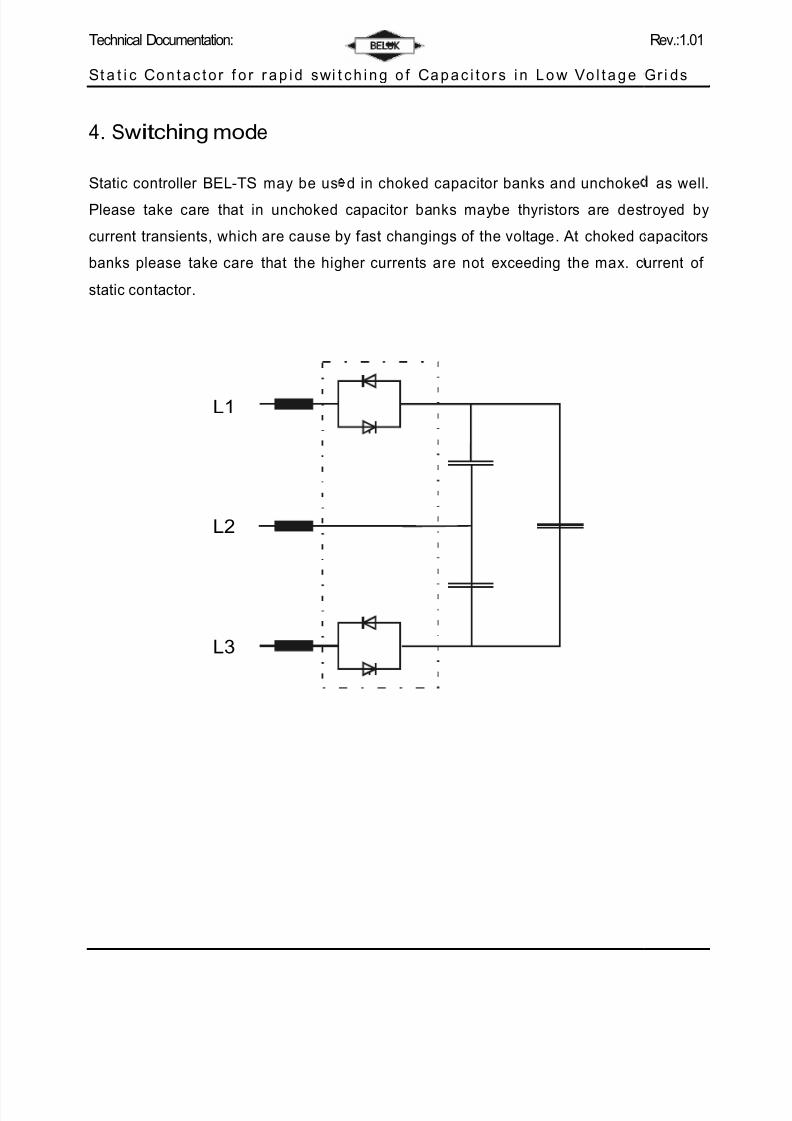
4. Switching mode
Static controller BEL-TS may be us
Please take care that in unchoked
current transients, which are cause b
banks please take care that the hig
static contactor .
L1
L2
L3
c h i n g o f Ca p a c i t o r s i n L o w Vo l t a g e
d in choked capacitor banks and unchoke
capacitor banks maybe thyristors are dest
y f ast changings of the voltage. At choked c
her currents are not exceeding the max. c
Rev.:1.01
Gr i ds
as well.
royed by
apacitors
urrent of
Page 8
8/13/2019 Static Swtich ~ Operating Instructions
http://slidepdf.com/reader/full/static-swtich-operating-instructions 8/16
Technical Documentation:
St a t i c Co n t a c t o r f o r r a p i d sw i t
5. Installation of the static
Thyristor switches of type BEL-TS hais caused. typically this is achieved b
When installing the switc hes it is
generated, which have to be han
continuous operation temperatures u
this the static contactor has to be mo
are damaged because of the high te
Additionally it is prohibited, that co
insulation can melt and shor t circuits
Generally static contactors should be
By assembling them ver tical it must b
the heat sink.
Additionally the switchboard must b
cabinet must not exceed the limit f or
the thyristor manuf acturer .
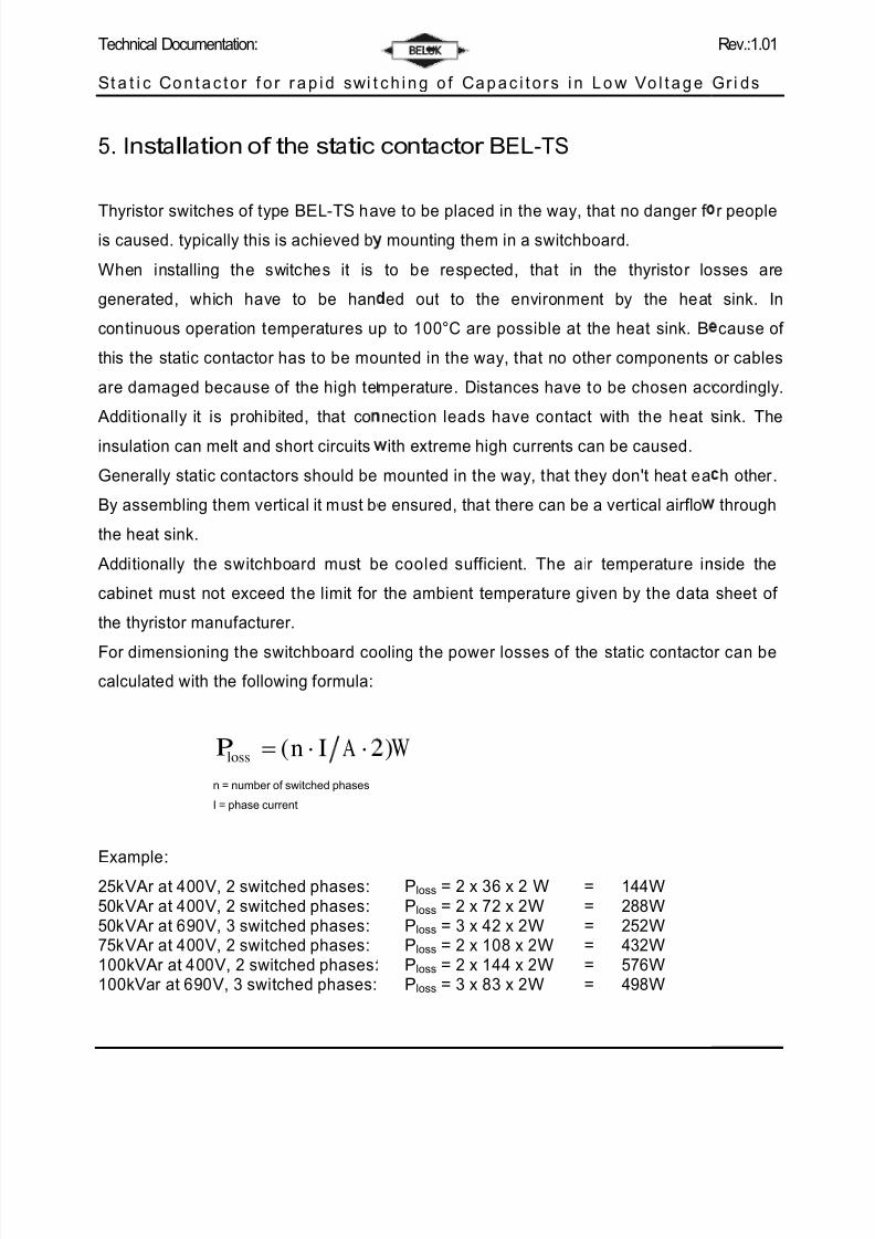
For dimensioning the switchboard co
calculated with the f ollowing f ormula:
Ploss (n I A
n = number of switched phases
I = phase current
Example:
25kVAr at 400V, 2 switched phases:50kVAr at 400V, 2 switched phases:50kVAr at 690V, 3 switched phases:75kVAr at 400V, 2 switched phases:100kVAr at 400V, 2 switched phases:100kVar at 690V, 3 switched phases:
c h i n g o f Ca p a c i t o r s i n L o w Vo l t a g e
contactor BEL-TS
ve to be placed in the way, that no danger f mounting them in a switchboard.
to be respected, that in the thyristor lo
ed out to the environment by the heat
p to 100°C are possible at the heat sink. B
unted in the way, that no other components
mperature. Distances have to be chosen ac
nection leads have contact with the heat
ith extreme high currents can be caused.
mounted in the way, that they don't heat ea
e ensured, that there can be a ver tical air f lo
e cooled suff icient. The air temperature in
the ambient temperature given by the data
oling the power losses of the static contacto
)W
Ploss = 2 x 36 x 2 W = 144WPloss = 2 x 72 x 2W = 288WPloss = 3 x 42 x 2W = 252WPloss = 2 x 108 x 2W = 432WPloss = 2 x 144 x 2W = 576WPloss = 3 x 83 x 2W = 498W
Rev.:1.01
Gr i ds
r people
sses are
sink. In
cause of
or cables
cordingly.
sink. The
h other .
through
side the
sheet of
r can be
Page 9
8/13/2019 Static Swtich ~ Operating Instructions
http://slidepdf.com/reader/full/static-swtich-operating-instructions 9/16
Technical Documentation:
St a t i c Co n t a c t o r f o r r a p i d sw i t
When dimensioning the cabinet cooli
or capacitors, have to be included.
It is advantageous, when the static c
can directly exhaust of the cabinet.
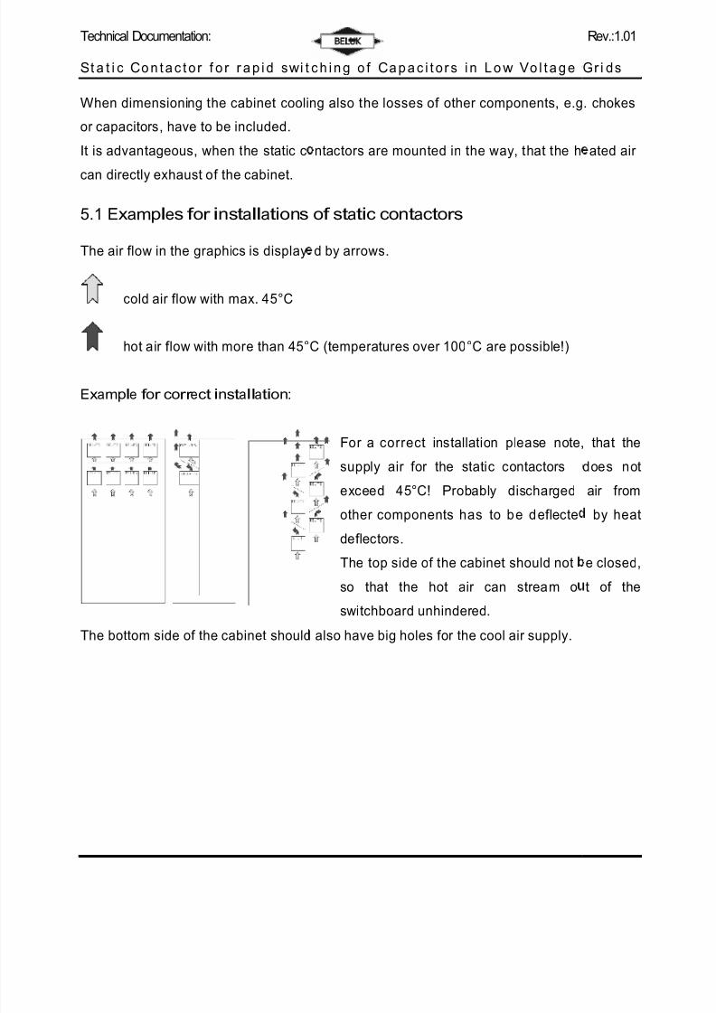
5.1 Examples f or installations
The air f low in the graphics is display
cold air f low with max. 45°C
hot air f low with more than 45°
Example f or corr ect installation:
The bottom side of the cabinet should
c h i n g o f Ca p a c i t o r s i n L o w Vo l t a g e
ng also the losses of other components, e.g
ntactors are mounted in the way, that the h
of static contactor s
d by arrows.
C (temperatures over 100°C are possible!)
For a correct installation please note,
supply air f or the static contactors
exceed 45°C! Probably discharged
other components has to b e d ef lecte
def lectors.
The top side of the cabinet should not
so that the hot air can stream o
switchboard unhindered.
also have big holes f or the cool air supply.
Rev.:1.01
Gr i ds
. chokes
ated air
that the
does not
air f rom
by heat
e closed,
t of the
Page 10
8/13/2019 Static Swtich ~ Operating Instructions
http://slidepdf.com/reader/full/static-swtich-operating-instructions 10/16
Technical Documentation:
St a t i c Co n t a c t o r f o r r a p i d sw i t
Examples f or wr ong installation:
a)
b)
Attention: installatio
The static contactors
generated. Because o
Despite of the corre
suff iciently. This caus
temperature a shor t-
provoked.
c h i n g o f Ca p a c i t o r s i n L o w Vo l t a g e
Attention: installation err or !
The static contactors are placed in the
the cooling air of the bottom switches
switches placed above. This cause
overload and dependent on the
temperature a shor t- or middle-term
of the thyristors can be provoked.
err or !
are placed in the way, that no ver tical a
f this the cooling capacity of the heat sink is
t ambient temperature the thyristors are
es thermal overload and dependent on th
or middle-term demolition of the thyristors
Rev.:1.01
Gr i ds
way, that
heats the
thermal
ambient
emolition
ir f low is
reduced.
't cooled
ambient
can be
Page 11
8/13/2019 Static Swtich ~ Operating Instructions
http://slidepdf.com/reader/full/static-swtich-operating-instructions 11/16
Technical Documentation:
St a t i c Co n t a c t o r f o r r a p i d sw i t
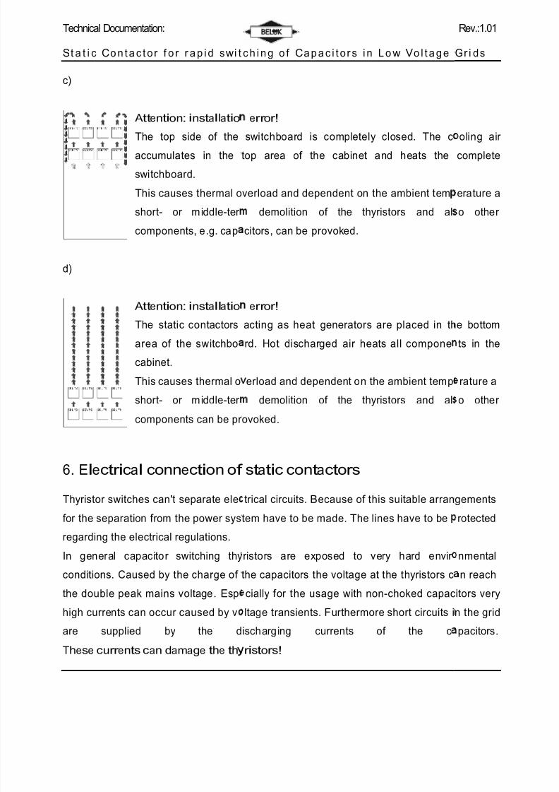
c)
Attention: installatio
The top side of theaccumulates in the
switchboard.
This causes thermal o
shor t- or m iddle-ter
components, e.g. cap
d)
Attention: installatio
The static contactors
area of the switchbo
cabinet.
This causes thermal o
shor t- or m iddle-ter
components can be pr
6. Electr ical connection of
Thyristor switches can't separate ele
f or the separation f rom the power sys
regarding the electrical regulations.
In general capacitor switching thy
conditions. Caused by the charge of
the double peak mains voltage. Esp
high currents can occur caused by v
are supplied by the d
These curr ents can damage the th
c h i n g o f Ca p a c i t o r s i n L o w Vo l t a g e
err or !
switchboard is completely closed. The ctop area of the cabinet and heats the
verload and dependent on the ambient tem
demolition of the thyristors and al
citors, can be provoked.
err or !
acting as heat generators are placed in th
rd. Hot discharged air heats all compone
erload and dependent on the ambient temp
demolition of the thyristors and al
ovoked.
static contactor s
trical circuits. Because of this suitable arran
tem have to be made. The lines have to be
ristors are exposed to very hard envir
the capacitors the voltage at the thyristors c
cially f or the usage with non-choked capac
ltage transients. Fur thermore shor t circuits i
ischarging currents of the c
r istor s!
Rev.:1.01
Gr i ds
oling air complete
erature a
o other
e bottom
ts in the
rature a
o other
gements
rotected
nmental
n reach
itors very
n the grid
pacitors.
Page 12
8/13/2019 Static Swtich ~ Operating Instructions
http://slidepdf.com/reader/full/static-swtich-operating-instructions 12/16
Technical Documentation:
St a t i c Co n t a c t o r f o r r a p i d sw i t
Thus it is recommended to protect t
ref erring values f or the f uses h
semiconductor f uses don't protect th
lines (gL) and f or the thyristors (gR)possible.
7. Maintenance of static c
Generally thyristor switches are mai
be respected:
- Thyristor switches , equippe
f unc tion every 2 years. If a f an
Using another f an with less ai
thyristors.
- Generally the heat sinks have
can be reduced by pollution.
- Pollution between the conne
because of this leakage distan
c h i n g o f Ca p a c i t o r s i n L o w Vo l t a g e
e static contactors in critical cases with f u
ve to be reque sted. Please respect t
lines. Because of this a combination of f us
as to be chosen. The usage of f uses type g
ntactor s
tenance-f ree. But never theless some points
with f an, have to be checked f or the c
is def ective, it has to be replaced by the ori
f low can cause overheating and this can d
o be cleaned regularly, because the cooling
tions of the thyristors have also to be r
es are reduced. This can cause a voltage f l
Rev.:1.01
Gr i ds
es. The
hat pure
s f or the
L is also
have to
rrect f an
inal par t.
stroy the
capacity
emoved,
shover .
Page 13
8/13/2019 Static Swtich ~ Operating Instructions
http://slidepdf.com/reader/full/static-swtich-operating-instructions 13/16
Technical Documentation:
St a t i c Co n t a c t o r f o r r a p i d sw i t
8. Technical Data
Power section max. mainsvoltage
Nominal current
Max. continuous current(IRMS AC) Thyristor/Thyrist(at max. 45°C ambienttemperature)
I2t; T =125°C; 8,3 ... 10 mvj
Discharging of capacitors
Recovery time
Fir ing Unit Auxiliary voltage
Consumption
Voltage level of trigger sig
Consumption trigger sign
Temperature range
DC – supply for external u
Common data Weight / kg:
Dimensions H x W x D /
Cooling:
Protection degreet
Humidity
max. altitude
Ambient tem per ature
c h i n g o f Ca p a c i t o r s i n L o w Vo l t a g e
BEL-TS
25H2
BEL-TS
50H2
BEL-TS
75H2
525V, 50/60 Hz
37 A 72,5 A 110 A
or 45 A 90 A 145 A
sec 3600 A2s 15000 A
2s 15000 A
2s
Discharging resistors
20ms
230/400V +10% -20% 50/60 Hz
9 VA
nal 8 – 30 V DC
l 2 mA bei 12 V DC
-10°C - +60°C (only trigger unit!)
se 12 V DC, 50 mA
5,0 5,0 8,0
m 170x170x230 170x170x230 240x275x181
AN(natural)
AN(natural)
AF(forced)
IP00
10 – 95%, without moisture condensa
1000m above sea level
-10 °C - +45 °C
Rev.:1.01
Gr i ds
BEL-TS
100H2
145 A
193 A
125000 A2s
8,0 kg
40x275x181
AF(forced)
tion
Page 14
8/13/2019 Static Swtich ~ Operating Instructions
http://slidepdf.com/reader/full/static-swtich-operating-instructions 14/16
Technical Documentation:
L 1
L 2
L 3
L a s t
l o a d
P E
A u x i l i a r y v o l t a g e
2 3 0 V
4 0 0 V
2 3 0 V
St a t i c Co n t a c t o r f o r r a p i d sw i t
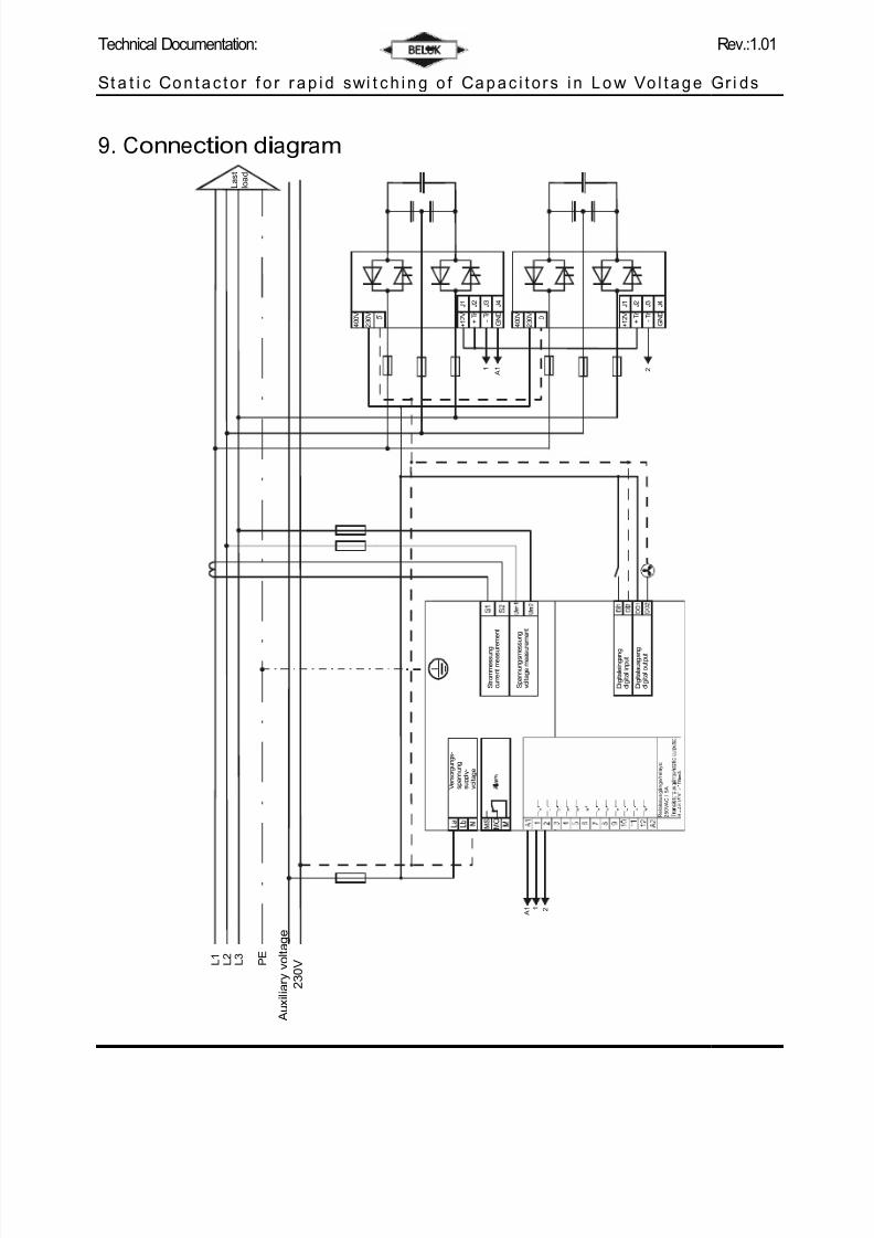
9. Connection diagr am
0
V e r s o r g u n g s -
s p a n n u n g
s u p p l y -
v o l t a g e
+ 1 2 V
J 1
+ T r
J 2
- T r
J 3
G N D
J 4
1 A 1
S t r o m m e s s u n g
c u r r e n t m e a s u
r e m e n t
4 0 0 V
2 3 0 V
0
S p a n n u n g s m e
s s u n g
v o l t a g e m e a s u
r e m e n t
A 1 1 2
D i g i t a l e i n g a n g
d i g i t a l i n p u t
D i g i t a l a u s g a n g
d i g i t a l o u t p u t
+ 1 2 V
J 1
+ T r
J 2
- T r
J 3
G N D
J 4
2
R e l a i s a u s g ä n g e / r e l a y s :
2 5 0 V A C
/ 5 A
c h i n g o f Ca p a c i t o r s i n L o w Vo l t a g e
Rev.:1.01
Gr i ds
Page 15
8/13/2019 Static Swtich ~ Operating Instructions
http://slidepdf.com/reader/full/static-swtich-operating-instructions 15/16
Technical Documentation:
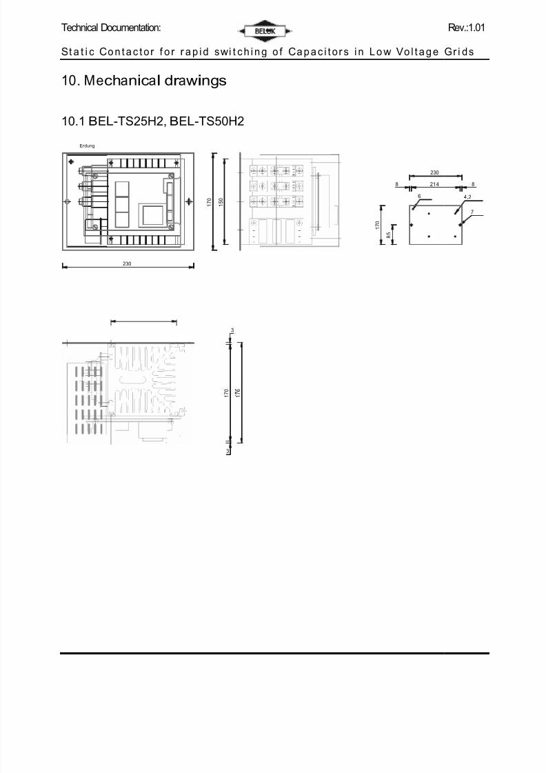
1 7 0
1 5 0
1 7 0
St a t i c Co n t a c t o r f o r r a p i d sw i t
10. Mechanical dr awings
10.1 BEL-TS25H2, BEL-TS50H
Erdung
230
3
3
1 7 6
1 7 0
8
5
c h i n g o f Ca p a c i t o r s i n L o w Vo l t a g e
2
230
8 214
6
Rev.:1.01
Gr i ds
8
4,2
7
Page 16
8/13/2019 Static Swtich ~ Operating Instructions
http://slidepdf.com/reader/full/static-swtich-operating-instructions 16/16
Technical Documentation:
St a t i c Co n t a c t o r f o r r a p i d sw i t
10.2 BEL-TS75H2, BEL-TS100
c h i n g o f Ca p a c i t o r s i n L o w Vo l t a g e
H2
Rev.:1.01
Gr i ds


![The SIGSPATIAL Special · ing. Ridesharing can be either static or dynamic [9, 10]. Most ridesharing systems operating today belong to static ridesharing, which arrange the driver](https://static.documents.pub/doc/80x56/5ed37bb0847f87317f77be5b/the-sigspatial-special-ing-ridesharing-can-be-either-static-or-dynamic-9-10.jpg)


