29
Statistical Characterization of the Multipath Rayleigh-faded Mobile Radio Channels

Statistical Characterization of
the Multipath Rayleigh-faded
Mobile Radio Channels

Technical University of Cluj-Napoca Faculty of Electronics and Telecommunications
Statistical Characterization of the Multipath Rayleigh-faded Mobile Radio Channels 2
Table of contents
Table of contents ...................................................................................................................2
Introduction ...........................................................................................................................3
Doppler shift .....................................................................................................................3
Coherence bandwidth ........................................................................................................4
Doppler spread and coherence time ...................................................................................4
Types of small-scale fading ...............................................................................................5
Flat fading .....................................................................................................................5
Frequency selective fading.............................................................................................5
Fast fading .....................................................................................................................6
Slow fading ...................................................................................................................6
Rayleigh fading distribution ..............................................................................................6
Mathematical modeling of the multipath Rayleigh faded radio channel ..............................7
Channel statistics calculation .................................................................................................8
Theoretical approach .........................................................................................................8
Infinite series for computation of the probability density function of a sum of Rayleigh random variables ...........................................................................................................8
Computation of the global p.d.f.................................................................................... 11 The program .................................................................................................................... 12
Graphical interface ...................................................................................................... 12 The flowchart of the program....................................................................................... 14
Implementation ............................................................................................................ 15 Results............................................................................................................................. 16
Simulation of a Rayleigh fading channel ............................................................................. 19 Theoretical approach ....................................................................................................... 19
The program .................................................................................................................... 19 Implementation ............................................................................................................ 19
Results............................................................................................................................. 20 Comparison of the results .................................................................................................... 21
Possible practical application ............................................................................................... 24
The basic idea .................................................................................................................. 24 The Emulate fading program ........................................................................................... 25
The graphical interface ................................................................................................ 26 Flowchart .................................................................................................................... 27
References ........................................................................................................................... 29

Technical University of Cluj-Napoca Faculty of Electronics and Telecommunications
Statistical Characterization of the Multipath Rayleigh-faded Mobile Radio Channels 3
Introduction
Many physical factors in radio propagation channels influence small-scale fading. These include the following:
• Multipath propagation – The presence of reflecting objects and scatterers in the
channel creates a constantly changing environment that dissipates the signal energy in amplitude, phase, and time. These effects result in multiple versions of the
transmitted signal that arrive at the receiving antenna, displaced with respect to one another in time and spatial orientation. The random phase and amplitudes of the
different multipath components cause fluctuations in signal strength, thereby inducing small-scale fading, signal distortion, or both. Multipath propagation often lengthens
the time required for the baseband portion of the signal to reach the receiver which can cause signal smearing due to intersymbol interference.
• Speed of the mobile – The relative motion between the base station and the mobile results in random frequency modulation due to different Doppler shifts on each of the multipath components. Doppler shift will be positive or negative depending on
whether the mobile receiver is moving toward or away from the base station.
• Speed of surrounding objects – If objects in the radio channel are in motion, they
induce a time varying Doppler shift on multipath components. If the surrounding
objects move at a greater rate than the mobile, then this effect dominates the small-
scale fading. Otherwise, motion of the surrounding objects may be ignored, and only
the speed of the mobile need be considered.
• The transmission bandwidth of the signal – If the transmitted radio signal bandwidth is greater than the bandwidth of the multipath channel, the received signal will be
distorted but the received signal strength will not fade much over a local area. The
bandwidth of the channel can be quantified by the coherence bandwidth which is
related to the specific multipath structure of the channel. The coherence bandwidth is
a measure of the maximum frequency difference for which signals are still strongly
correlated in amplitude. [2]
Doppler shift
Consider a mobile moving at a constant velocity v, along a path segment having
length d between points X and Y, while it receives signals from a remote source S. The
difference in path lengths traveled by the wave from source S to the mobile at points X and Y
is cos cosl d v tθ θ∆ = = ∆ (1), where t∆ is the time required for the mobile to travel from X
to Y, and θ is assumed to be the same at points X and Y since the source is assumed to be
very far away. The phase change in the received signal due to the difference in path lengths is
therefore 2 2
cosl v tπ π
φ θλ λ
∆ ∆∆ = = (2) and hence the apparent change in frequency, or
Doppler shift, is given by df , where
1cos
2d
vf
t
φθ
π λ
∆= =
∆ (3). This equation relates the
Doppler shift to the mobile velocity and the spatial angle between the direction of motion of
the mobile and the direction of arrival of the wave. If the mobile is moving toward the

Technical University of Cluj-Napoca Faculty of Electronics and Telecommunications
Statistical Characterization of the Multipath Rayleigh-faded Mobile Radio Channels 4
direction of arrival of the wave, the Doppler shift is positive, and if the mobile is moving away from the direction of arrival of the wave, the Doppler shift is negative.[2]
Coherence bandwidth
Delay spread and coherence bandwidth are parameters which describe the time
dispersive nature of the channel in a local area. Coherence bandwidth is a statistical measure
of the range of frequencies over which the channel can be considered “flat”. In other words,
coherence bandwidth is the range of frequencies over which two frequency components have
a strong potential for amplitude correlation. Two sinusoids with frequency separation greater
than cB are affected quite differently by the channel. If the coherence bandwidth is defined
as the bandwidth over which the frequency correlation is above 0.9, then the coherence
bandwidth is approximately given by 1
50c
t
Bσ
≈ (4). If the definition is relaxed so that the
frequency correlation function is above 0.5, then the coherence bandwidth is approximately
expressed by 1
5c
t
Bσ
≈ (5). An exact relationship between coherence bandwidth and rms
delay spread does not exist. [2]
Doppler spread and coherence time
Doppler speed and coherence time are parameters which describe the time varying
nature of the channel in a small-scale region.
Doppler spread DB is a measure of the spectral broadening caused by the time rate of
change of the mobile radio channel and is defined as the range of frequencies over which the
received Doppler spectrum is essentially non-zero. When a pure sinusoidal tone of frequency
cf is transmitted, the received signal spectrum, called the Doppler spectrum, will have
components in the range c df f− to
c df f+ , where df is the Doppler shift. If the baseband
signal bandwidth is much greater than DB , the effects of Doppler spread are negligible at the
receiver.
Coherence time cT is the time domain dual of Doppler spread and is used to
characterize the time varying nature of the frequency dispersiveness of the channel in the
time domain. The Doppler spread and coherence time are inversely proportional to one
another. That is, 1
c
m
Tf
≈ (6). Coherence time is actually a statistical measure of the time
duration over which the channel impulse response is essentially invariant, and quantifies the similarity of the channel response at different times. In other words, coherence time is the
time duration over which two received signals have a strong potential for amplitude
correlation. If the coherence time is defined as the time over which the time correlation
function is above 0.5, then the coherence time is approximately 9
16c
m
Tfπ
≈ (7), where mf is
the maximum Doppler shift given by /mf v λ= (8). In practice, a popular rule for modern
digital communications is to define the coherence time as the geometric mean of the

Technical University of Cluj-Napoca Faculty of Electronics and Telecommunications
Statistical Characterization of the Multipath Rayleigh-faded Mobile Radio Channels 5
preceding equations. That is, 2
9 0.423
16c
m m
Tf fπ
= = (9). The definition of coherence time
implies that two signals arriving with a time separation greater than cT are affected
differently by the channel. [2]
Types of small-scale fading
Depending on the relation between the signal parameters (such as bandwidth, symbol
period, etc.) and the channel parameters (such as rms. delay spread and Doppler spread),
different transmitted signals will undergo different types of fading. The time dispersion and
frequency dispersion in mobile radio channels lead to four possible distinct effects, which are manifested depending on the nature of the transmitted signal, the channel, and the velocity.
While multipath delay spread leads to time dispersion and frequency selective fading, Doppler spread leads to frequency dispersion and time selective fading. [3]
Small-Scale Fading (Based on multipath time delay spread)
Flat Fading Frequency selective fading BW of signal < BW of channel BW of signal > BW of channel
Delay spread < Symbol period Delay spread > Symbol period Small-Scale Fading
(Based on Doppler spread)
Fast Fading Slow Fading
High Doppler spread Low Doppler spread Coherence time < Symbol period Coherence time > Symbol period
Channel variations faster than Channel variations slower than baseband signal variations baseband signal variations
Flat fading
If the mobile radio channel has a constant gain and a linear phase response over a
bandwidth which is greater than the bandwidth of the transmitted signal, then the received
signal will undergo flat fading. This type of fading is the most common type of fading
described in the technical literature. In flat fading, the multipath structure of the channel is
such that the spectral characteristics of the transmitted signal are preserved at the receiver. However the strength of the received signal changes with time, due to fluctuations in the gain
of the channel caused by multipath. Flat fading channels are also known as amplitude varying channels and are often referred to as narrowband channels, since the bandwidth of
the transmitted signal is narrow as compared to the channel flat fading bandwidth.
Frequency selective fading
If the channel possesses a constant-gain and linear phase response over a bandwidth
that is smaller than the bandwidth of transmitted signal, then the channel creates frequency
selective fading on the received signal. The channel impulse response has a multipath delay spread which is greater than the reciprocal bandwidth of the transmitted message waveform.
The received signal includes multiple versions of the transmitted waveform which are attenuated and delayed in time, and hence the received signal is distorted. Frequency
selective fading is due to time dispersion of the transmitted symbols within the channel. The

Technical University of Cluj-Napoca Faculty of Electronics and Telecommunications
Statistical Characterization of the Multipath Rayleigh-faded Mobile Radio Channels 6
channel induces intersymbol interference. Viewed in the frequency domain, certain frequency components have greater gains than others. Frequency selective fading channels
are difficult to model since each multipath signal must be modeled and the channel must be considered to be a linear filter. For frequency selective fading, the spectrum of the
transmitted signal has a bandwidth which is greater than the coherence bandwidth of the channel. Frequency selective fading is caused by multipath delays which approach or exceed
the symbol period of the transmitted symbol. Frequency selective fading channels are also known as wideband channels since the bandwidth of the signal is wider than the bandwidth
of the channel impulse response.
Fast fading
In a fast fading channel, the channel impulse response changes rapidly within the
symbol duration. The coherence time of the channel is smaller than the symbol period of the
transmitted signal. This causes frequency dispersion due to Doppler spreading, which leads
to distortion. Viewed in the frequency domain, signal distortion increases with increasing
Doppler spread relative to the bandwidth of the transmitted signal. Fast fading only deals
with the rate of change of the channel due to motion.
Slow fading
In a slow fading channel, the channel impulse response changes at a rate much slower
than the transmitted baseband signal. In this case, the channel may be assumed to be static
over one or several reciprocal bandwidth intervals. In frequency domain, this implies that the
Doppler spread of the channel is much less than the bandwidth of the baseband signal. [2]
Rayleigh fading distribution
In mobile radio channels, the Rayleigh distribution is used to describe the statistical time varying nature of the received envelope of an individual multipath component. The
envelope of the sum of two quadrature Gaussian noise signal is a Rayleigh distribution. The Rayleigh distribution has a probability density function (p.d.f.) given by
2
2 2exp (0 )
( ) 2
0 ( 0)
r rr
p r
r
σ σ
− ≤ ≤ ∞
= <
(10),
where σ is the rms. value of the received signal before envelope detection, and 2σ is the
time-average power of the received signal before envelope detection. The mean value of the
Rayleigh distribution is given by
0
[ ] ( ) 1.25332
meanr E r rp r dr
πσ σ
∞
= = = =∫ (11)
and the variance of the Rayleigh distribution is given by 2
2 2 2 2 2 2
0
[ ] [ ] ( ) 2 0.42922 2
rE r E r r p r dr
σ π πσ σ σ
∞
= − = − = − =
∫ (12).
The median value of r is 1.177medianr σ= (13). [2]

Technical University of Cluj-Napoca Faculty of Electronics and Telecommunications
Statistical Characterization of the Multipath Rayleigh-faded Mobile Radio Channels 7
Mathematical modeling of the multipath Rayleigh faded radio channel
Possible solutions proposed in literature: 1. An infinite series for the computation of the c.d.f. and p.d.f. of sums of random
variables (particular case of Rayleigh variables) [4]
• A number of several thousands of terms are required to obtain a good approximation
of the p.d.f. of sums of random variables.
• It considers only the sum of real random variables – the phase variations induced by
multipath propagation and random phase variations induced by the small scale fading are not considered.
2. Computation of the p.d.f of sums of random vectors, with identically and arbitrarily
distributed lengths and uniformly distributed phases [7]
• Integration of the multipath propagation situation is required (phase distributed
uniformly but with imposed mean value) .
• The p.d.f. obtained can be expressed as a definite integral including Bessel functions
– the obtained p.d.f. of the vector length can be expressed by Hankel transform H0a,
where J0 is the zero order Bessel function and Ex-y is the expectation of the combined
vector
(14)
• The previous p.d.f. can be decomposed as a a series of Laguere polynomial, easier to
compute than the definite integral 3. Closed-form upper-bound for the distribution of the weighted sum of Rayleigh
variables [9]
• An upper-bound is defined for the sum of Rayleigh distributed variables.
• The phase variations due to the multipath propagation and small scale fading are not
considered.
• The proposed upper-bound relies on G Meijer’s functions – very difficult to compute
in the general case. 4. Computing the distribution of sums of random sine waves and of Rayleigh-
distributed random variables by saddle-point integration [8]
• The c.d.f. of a sum of independent random variables can be computed according to
the following integral on a curve, where h(z) is the moment generating function of the
v variable:
(15)
• Saddle point integration is proposed to compute the previous integral; the saddle point which has to be found as well the moment generating function.
• Random phases and Rayleigh distributed amplitudes are considered separately
( ) ( ) ( ) ( ){ } ( ) ( )
⋅⋅=ΛΛ⋅=⋅Λ⋅⋅⋅⋅= ∏∫
=−
∞ n
i
iAAa AJEHadaJaafdpN
1
00
0
0 1;... ξξξξξξξ
( ) ( ) ( ) ( ) ( )( )∫ ±−⋅−=Φ⋅= Φ
C
zzvzzhz
j
dzevfdc lnln;
2...
π

Technical University of Cluj-Napoca Faculty of Electronics and Telecommunications
Statistical Characterization of the Multipath Rayleigh-faded Mobile Radio Channels 8
Channel statistics calculation
Theoretical approach
Infinite series for computation of the probability density function of a sum of Rayleigh random variables
The problem of determining the distribution function, or equivalently the
complementary distribution function, of a sum of independent random variables, each of
which possesses a Rayleigh distribution function has been of interest for the past 90 years.
[4]
A convergent infinite series may be used for the computation of the complementary
probability distribution function (c.d.f.) of a sum of independent Rayleigh random variables.
Let , 1,...,iX i L= be bounded independent random variables each with p.d.f. ( )iX if x such that
( ) 0iX if x = for all L
i ix B< or U
i ix B> . Denote the sum of the L random variables by X,
1
L
i
i
X X=
=∑ , the c.d.f.. X by ( )XG x , and the p.d.f.. of X by ( )Xf x . Then X is lower bounded
by 1
LL
L i
i
B B=
=∑ and upper bounded by 1
LU
U i
i
B B=
=∑ . Let S(x) denote the periodic square wave
given by:
0, / 2 0
( ) 1, 0 / 2
1/ 2, / 2
T x
S x x T
x T
− < <
= < < = ±
(16)
( ) ( ), 0, 1, 2,...S x mT S x m+ = = ± ± (17)
Then:
( ) Pr( ) [ ( )]XG L X L E S X Lε ε ε= > = − (18),
where E[X] denotes the expected value of X. This equation is true for:
{ }/ 2 max ,U LT B L L Bε ε= − − (19).
The Fourier series representation of S(x) is:
1 1( ) ,
2
jn x
n n
nn impar
S x C e Cnj
ω
π
∞
=−∞
= + =∑ , where 2
T
πω = (20).
The combination of the above equations gives:

Technical University of Cluj-Napoca Faculty of Electronics and Telecommunications
Statistical Characterization of the Multipath Rayleigh-faded Mobile Radio Channels 9
( )
( ) ( )
1
1 1
1
( )
1
1( ) [ ]
2
1
2
exp exp1
2
1
2
i
jn X L
X n
nn impar
jn X L jn X L
nn impar
L L
i i
i i
nn impar
Ljn X
i
G L C E e
E e E e
n j
E jn X L E jn X L
n j
E e
ω ε
ω ε ω ε
ω ε
ε
π
ω ε ω ε
π
∞−
=−∞
− − −∞
=
∞= =
=
−
=
= +
− = +
− − − −
= +
= +
∑
∑
∑ ∑∑
( )
1
1
1 1
1
1 11 1
1
1
1
2
exp exp1
2
1
2
sin1 2
2
i
in in
n n
Ljn X
i
nn impar
L Lj j
in in
i i
nn impar
L LL L
in in in in
i ii i
nn impar
j j
n n
nn impar
n n
E e
n j
A e A e
n j
j A j A
n j
A e A e
n j
A
ω ε
θ θ
θ θ
π
π
θ θ
π
π
θ
π
− −
∞=
=
−
∞= =
=
∞= == =
=
−∞
=
−
−
= +
− −
= +
−= +
= +
∏ ∏∑
∏ ∏∑
∑ ∑∏ ∏∑
∑
1nn impar
n
∞
=
∑
(21)
The Rayleigh p.d.f.. is:
2 2/ 2
2, 0
( )
0,
i
i
xii
iX i
xe x
f x
in rest
σ
σ−
≥=
(22),
where ( ) 22 / 2 iπ σ− is the variance of the distribution.
One has:
( ) ( )2 2
2
/ 2
2
0
2 2 2
/ 2
0
cos cos
1cos( ) 1, ,
2 2
i ixi
i i i
i
u ii
xE n X e n x dx
nue n u du F
σω ωσ
ω σωσ
∞−
∞−
=
−= =
∫
∫
(23), and

Technical University of Cluj-Napoca Faculty of Electronics and Telecommunications
Statistical Characterization of the Multipath Rayleigh-faded Mobile Radio Channels 10
( ) ( )2 2
2 2 2
/2
2
0
2 2 2/2
sin sin
3 3, ,
2 2 2 2 2
σ
ω σ
ω ωσ
ω σπ πωσ ωσ
∞−
−
=
−= =
∫ i i
i
xi
i i i
i
nii i
xE n X e n x dx
nn F n e
(24)
where F(.,.,.) is the hypergeometric function.
Combining these two equations gives:
2 2 2
2 2 2
2 2 2
22 2 2
2 2 2
2 2 2/ 22
1
2 2 2/ 22
11, ,
2 2 2
1cos( ) 1, , sin( )
2 2 2tan
11, , cos( ) sin( )
2 2 2
i
i
i
niin i
n ii
in
nii
nA F n e
nn e n F n
nF n n e n
ω σ
ω σ
ω σ
ω σ πω σ
ω σπωσ ωε ωε
θω σ π
ωε ωσ ωε
−
−
−
−
−= +
−−
= − +
(25)
Using a Kummer transformation one has:
1 1 11, , , ,
2 2 2
aF a e F a
− − = −
(26)
for which the confluent hypergeometric function on the right side has infinite series
expansion:
2 3
2 3
1 1 1 1 1 3
1 1 2 2 2 2 2 2, , 1 ...
1 1 3 1 3 52 22! 3!
2 2 2 2 2 2
1 ...3 2! 5 3!
a a a
F a
a aa
− − −
− = + + + +
= − − − −⋅ ⋅
(27)
This series converges much more rapidly than one obtained without applying the
Kummer transformation.
The error from truncation after N terms is given by:
1 (2 1) !
i
N
i N
aR
i i
∞
= +
= −−
∑ (28), and
( )
1
1 0
1
1
2 1 ! 2 1 ( 1)! 2
( 2)
(2 1)( 1)!( 2 )
ii N
N
i N i
N
a a aR
i i N N N
a N
N N N a
+∞ ∞
= + =
+
= <
− + + +
+=
+ + + −
∑ ∑, for a<N+2 (29).

Technical University of Cluj-Napoca Faculty of Electronics and Telecommunications
Statistical Characterization of the Multipath Rayleigh-faded Mobile Radio Channels 11
Therefore,
( )0
11, ,
2 2 1 !
ia
i
aF a e
i i
∞−
=
− = −
− ∑ (30)
and the magnitude of the truncation error is upper bounded by:
1( 2)
(2 1)( 1)!( 2 )
Na a N
error eN N N a
+− +
<+ + + −
(31)
Based on the c.d.f. the p.d.f. may be calculated:
( ) ( )∑∞
=∞→
⋅⋅=
oddnn
nnT
X AT
xf1
cos4
lim θ (32) [4]
Computation of the global p.d.f.
The computation of the p.d.f. of the the amplitude of a signal affected by multipath
propagation and Rayleigh fading may be done by decomposing the signal on two axes, sine
and cosine, computation of the p.d.f. of the signal on both axes and then by the combination
of the two p.d.f. – see fig. 1. If we have a multipath propagation profile with N different
paths, characterized by the attenuation of the paths, ai, and the delays of the paths, τi, and if
each path has fading Rayleigh, than the received signal will be:
( ) ( ) ( )( ) ( ) ( )
( ) ( )( ) ( ) ( )( )∑ ϕ⋅⋅⋅⋅ω+∑ ϕ⋅⋅⋅⋅ω=
=∑ ϕ−⋅ω⋅⋅=∑ τ−⋅ω⋅⋅=
−
=
−
=
−
=
−
=
1N
0iiitc
1N
0iiitc
1N
0iicit
1N
0iicitr
2sinaAFtsin2cosaAFtcos
tcos2aAFtcos2aAFts
(33)
It is considered that the Rayleigh fading does not affect the phase of the signal, only the
amplitude of the signal with multipath propagation.
On both axes we will obtain a sum of Rayleigh distributed variables. This method
proposes the usage of the finite series for the computation of the c.d.f.. Based on the c.d.f.,
the p.d.f. can be calculated. The p.d.f. is calculated only in points εL, which means that we
will obtain a sampled function, with a sampling step ∆L. The sampling step will be the same
on both axes. The sums of the random variables on the axes form two random variables Xcos
and Xsin, their module will form a random variable, Xv, which is uniformly distributed
according to a p.d.f. function fV(x). This is the function of interest. The probability that the
variable Xv is in a square of area (∆L)2 , square delimited by [eL , (e+∆)L] on the cosine axe
and [dL , (d+∆)L] on the sine axe, if the step ∆L is sufficiently small, is given by:
( ) ( )( )( )
( ) ( ) ( ) ( ) ( )2222
sincossincos LLdefLdLfeLfdydxyfxfp XvXX
Le
eL
Ld
dL
XXde ∆⋅⋅+=∆⋅⋅≈= ∫ ∫∆+ ∆+
−
(34)

Technical University of Cluj-Napoca
Faculty of Electronics and Telecommunications
Statistical Characterization of the Multipath Rayleigh-faded Mobile Radio Channels 12
Considering all the squares from the area delimited by the segments considered on the
cosine and sine axes the function which gives the probability that XV takes the values of
Lde ⋅+ 22 (35) may be determined – see fig. 1. Using a corresponding quantization we
can obtain the probability distribution that the value XV is on arches with radius L∆⋅2
(36). [1]
The program
The method described above was implemented in Borland C++ Builder 6. The user
interface of the mentioned software is presented in fig. 2
The graphical user interface
In the graphical user interface we can define different parameters of the multipath
channel.
• The attenuation of the reference path in dB
• The number of paths of a multipath channel
• The multipath propagation profile: we can introduce in a table the attenuation
and the delay of each path
• The central frequency of the channel
They are three checkboxes in the interface, using them we can select what the
application does:
• Calculate statistics of the channel
Figure 1 Combination of sine and cosine terms

Technical University of Cluj-Napoca
Faculty of Electronics and Telecommunications
Statistical Characterization of the Multipath Rayleigh-faded Mobile Radio Channels 13
• Simulate channel
• Calculate combined c.d.f. and p.d.f.
There is a window used o display the c.d.f.. and the p.d.f.. of each component.
The results of the calculus are saved in text files. There are 12 buttons to select which
graph we want to display. Pushing the button the results are read from the text file and
displayed in the window.
The buttons are the following:
For the statistics of the channel:
• c.d.f._cos – the c.d.f. of the cosine term
• c.d.f._sin – c.d.f. of the sine term
• c.d.f._vect – combined c.d.f.
• p.d.f._cos – p.d.f. of the cosine term
• p.d.f._sin – p.d.f. of the sine term
• p.d.f._vect – combined p.d.f.
For the channel simulation:
• c.d.f._cosc – the c.d.f. of the cosine term
• c.d.f._sinc – c.d.f. of the sine term
• c.d.f._vectc – combined c.d.f.
• p.d.f._cosc – p.d.f. of the cosine term
• p.d.f._sinc – p.d.f. of the sine term
• p.d.f._vectc – combined p.d.f.
We can also define the number of terms after which the series is truncated, the step
and the calculus domain.
In the graphical interface can be introduced the number of simulation terms.
Figure 2 The graphical user interface of the application

Technical University of Cluj-Napoca
Faculty of Electronics and Telecommunications
Statistical Characterization of the Multipath Rayleigh-faded Mobile Radio Channels 14
The flowchart of the program
Figure 3 The flowchart of the program

Technical University of Cluj-Napoca
Faculty of Electronics and Telecommunications
Statistical Characterization of the Multipath Rayleigh-faded Mobile Radio Channels 15
Implementation
Each multipath component has two terms in quadrature, a sinusoidal wave and a
cosinusoidal wave. These terms are obtained in the following way: First the attenuation is
transformed from decibels (amp_cale) and the delay from nanoseconds to seconds (int_cale).
Then a cosine wave is generated cos(2*pi*frecv_s*int_cale). This cosine is multiplied with
amp_cale, so we obtain the attenuation of the cosine term. For the sine term the procedure is
the same, except that we generate a sine wave sin(2*pi*frecv_s*int_cale).
If the checkbox for channel statistics calculation is checked and the button execute is
pushed, the program will execute the statistics computation. First the text files are opened.
The number of display points is calculated as computation domain / step. The computation
domain and the step are specified in the graphical interface of the program. Then the values
of upper and lower bound are read from the graphical interface. Future implementations of
the program may find an algorithm to calculate these values. Then the program calculates
{ }/ 2 max ,U LT B L L Bε ε= − − (37), and after that 2
T
πω = (38). In the graphical interface we
can specify the number of terms after which the series in truncated (n_term). The program
executes some computations for each sine and cosine term at the number of the series terms
times. These computations represent the following formulas:
2 2 2
2 2 2
2 2 2
22 2 2
2 2 2
2 2 2/ 22
1
2 2 2/ 22
11, ,
2 2 2
1cos( ) 1, , sin( )
2 2 2tan
11, , cos( ) sin( )
2 2 2
i
i
i
niin i
n ii
in
nii
nA F n e
nn e n F n
nF n n e n
ω σ
ω σ
ω σ
ω σ πω σ
ω σπωσ ωε ωε
θω σ π
ωε ωσ ωε
−
−
−
−
−= +
−−
= − +
(39)
We can identify for the cosine term the variables n=j, ω=p_om_c, σi=amp_cale_c,
ε=v_e_c. After this, the c.d.f... of each term is calculated, and based on the c.d.f. is obtained
the p.d.f.. of each term. These values are written in text files. After that the value of v_e_c is
incremented with a value equal to step/number of paths. For the sine term are executed the
same computations, only the names of the variables are different.
The program verifies if the checkbox for the combined statistics is checked. If it is,
the program will calculate the step size and the product of the sine term p.d.f.. and cosine
term p.d.f.. The values of the same interval are added and a histogram is generated. After that
the combined c.d.f.. is calculated. These values are written in text files.
When you push a button, the values are read from the corresponding text files and
then displayed in the display window.

Technical University of Cluj-Napoca
Faculty of Electronics and Telecommunications
Statistical Characterization of the Multipath Rayleigh-faded Mobile Radio Channels 16
Results
There were done simulations with different parameters for different multipath
channels.
In the following we will consider a channel with four multipath components. The
attenuations for this channel are 0, 3, 6, 9 dB and the delays are 0, 200, 400, 600 ns. The
series is truncated after 12000 terms.
The c.d.f. for the sin and cos components are the following:
Figure 4 Cosine c.d.f.
Figure 5 Sine c.d.f.

Technical University of Cluj-Napoca
Faculty of Electronics and Telecommunications
Statistical Characterization of the Multipath Rayleigh-faded Mobile Radio Channels 17
The combined c.d.f. will be:
Figure 6 Combined c.d.f.
The p.d.f. of the two terms will be:
Figure 7 Cosine p.d.f.

Technical University of Cluj-Napoca
Faculty of Electronics and Telecommunications
Statistical Characterization of the Multipath Rayleigh-faded Mobile Radio Channels 18
Figure 8 Sine p.d.f.
The combined p.d.f. (the envelope of the received signal) will be:
Figure 9 Combined p.d.f.

Technical University of Cluj-Napoca
Faculty of Electronics and Telecommunications
Statistical Characterization of the Multipath Rayleigh-faded Mobile Radio Channels 19
Simulation of a Rayleigh fading channel
Theoretical approach
A multipath Rayleigh faded channel can be modeled by adding Rayleigh fading to
each multipath component.
The Rayleigh distribution can be generated using two random variables with
Gaussian distribution.
A Box-Muller transform is a method for generating pairs of independent standard
normally distributed (zero expectation, unit variance) random numbers, given a source of
uniformly distributed random numbers.
Suppose 1U and
2U are independent random variables that are uniformly distributed
in the interval ( ]0,1 . Let
( )
( )
0 1 2
1 1 2
cos 2 ln cos 2
sin 2ln sin 2
Z R U U
Z R U U
θ π
θ π
= = −
= = − (40)
Then Z0 and Z1 are independent random variables with a normal distribution of
standard deviation 1. [5]
The program
Implementation
To simulate a mobile radio channel with fading Rayleigh we can use the same program, described above.
In the application interface can be defined the number of simulation terms. If the checkbox of the channel simulation is checked and the button execute is
pushed, the program will simulate a radio channel with Rayleigh fading. First are opened the text files, in these files will be written the p.d.f.. and c.d.f.. values. The number of terms of
simulation is read from the graphical interface. For each sine and cosines term will be generated a Rayleigh distribution using the Box-Muller transformation. This will be added to
the terms. This procedure will be repeated for each simulation term. After that the p.d.f. and
c.d.f. is computed and written in files.
If the checkbox for combined p.d.f. and c.d.f. is checked the program will calculate
these values and write them into text files.

Technical University of Cluj-Napoca Faculty of Electronics and Telecommunications
Statistical Characterization of the Multipath Rayleigh-faded Mobile Radio Channels 20
Results
Using the same multipath channel with four components we obtain the following
results:
Figure 10 Combined c.d.f.
Figure 11 Combined p.d.f.
Technical University of Cluj-Napoca Faculty of Electronics and Telecommunications
Statistical Characterization of the Multipath Rayleigh-faded Mobile Radio Channels 21
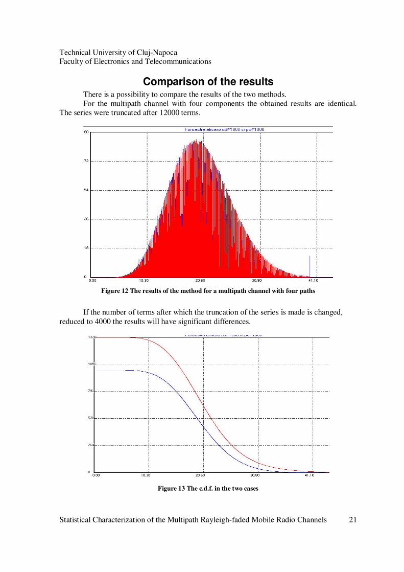
Comparison of the results There is a possibility to compare the results of the two methods.
For the multipath channel with four components the obtained results are identical.
The series were truncated after 12000 terms.
Figure 12 The results of the method for a multipath channel with four paths
If the number of terms after which the truncation of the series is made is changed,
reduced to 4000 the results will have significant differences.
Figure 13 The c.d.f. in the two cases

Technical University of Cluj-Napoca Faculty of Electronics and Telecommunications
Statistical Characterization of the Multipath Rayleigh-faded Mobile Radio Channels 22
The two p.d.f. functions will be also different, the envelope has different amplitude in the case of simulation and the case of statistics computation.
Figure 14 The p.d.f. in both cases
For a WP5 suburban macro channel, with 18 multipath components the results are the
following:
Figure 15 C.d.f.
Technical University of Cluj-Napoca Faculty of Electronics and Telecommunications
Statistical Characterization of the Multipath Rayleigh-faded Mobile Radio Channels 23
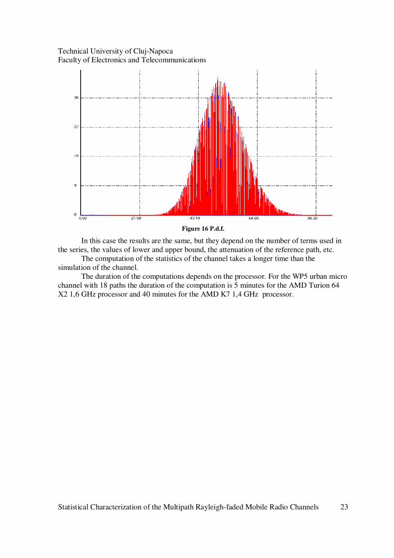
Figure 16 P.d.f.
In this case the results are the same, but they depend on the number of terms used in
the series, the values of lower and upper bound, the attenuation of the reference path, etc.
The computation of the statistics of the channel takes a longer time than the
simulation of the channel.
The duration of the computations depends on the processor. For the WP5 urban micro
channel with 18 paths the duration of the computation is 5 minutes for the AMD Turion 64
X2 1,6 GHz processor and 40 minutes for the AMD K7 1,4 GHz processor.
Technical University of Cluj-Napoca Faculty of Electronics and Telecommunications
Statistical Characterization of the Multipath Rayleigh-faded Mobile Radio Channels 24
Possible practical application
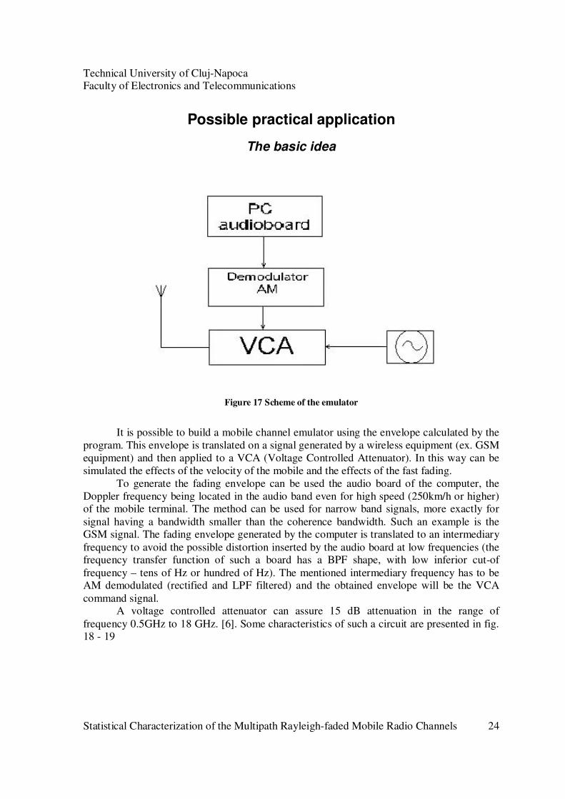
The basic idea
Figure 17 Scheme of the emulator
It is possible to build a mobile channel emulator using the envelope calculated by the
program. This envelope is translated on a signal generated by a wireless equipment (ex. GSM
equipment) and then applied to a VCA (Voltage Controlled Attenuator). In this way can be
simulated the effects of the velocity of the mobile and the effects of the fast fading.
To generate the fading envelope can be used the audio board of the computer, the
Doppler frequency being located in the audio band even for high speed (250km/h or higher) of the mobile terminal. The method can be used for narrow band signals, more exactly for
signal having a bandwidth smaller than the coherence bandwidth. Such an example is the GSM signal. The fading envelope generated by the computer is translated to an intermediary
frequency to avoid the possible distortion inserted by the audio board at low frequencies (the frequency transfer function of such a board has a BPF shape, with low inferior cut-of
frequency – tens of Hz or hundred of Hz). The mentioned intermediary frequency has to be AM demodulated (rectified and LPF filtered) and the obtained envelope will be the VCA
command signal. A voltage controlled attenuator can assure 15 dB attenuation in the range of
frequency 0.5GHz to 18 GHz. [6]. Some characteristics of such a circuit are presented in fig. 18 - 19

Technical University of Cluj-Napoca Faculty of Electronics and Telecommunications
Statistical Characterization of the Multipath Rayleigh-faded Mobile Radio Channels 25
Figure 18 Attenuation vs. control voltage
Figure 19 Attenuation vs. frequency
The Emulate fading program
A program, Emulate_fading may be used to generate a signal affected by fading or
only the envelope of the signal affected by fading. The fading envelope and the signal affected by fading are generated, and after then these signals may be saved as *.wav file. One
can open these files to visualize or analyze the fading envelope and it is possible to play these files. Once the file is played, it can go through to the audio board of the pc. On the output we
will have the signal translated to an intermediary frequency. To generate fading envelope distributed according different p.d.f. one can use the first
program.

Technical University of Cluj-Napoca Faculty of Electronics and Telecommunications
Statistical Characterization of the Multipath Rayleigh-faded Mobile Radio Channels 26
The graphical interface
Figure 20 Graphical interface of the emulate fading program
In the graphical interface of the application the user can define the following parameters:
• the carrier frequency in MHz
• the carrier amplitude in V, this amplitude should be smaller than 0.5 V
• the speed of the mobile in km/h
• the intermediate frequency to which the signal is translated in Hz
• the duration of the signal in s If the button Generate fading is pushed, the program will generate an envelope with
Rayleigh distribution and a sine signal with this envelope. The program will calculate the channel coherence time (= 0.423* 3e8/ speed/ carrier frequency [ms]) and the Doppler
frequency (= speed* carrier frequency/ 3e8 [Hz]). The user can also specify the parameters of the *.wav file: sampling frequency, number
of channels, the number of bits/sample. The generated signal can be saved in a *.wav file. Once this file is opened, the generated
signal can be played, or the envelope of the signal can be displayed / analyzed. The number of points of the histogram can be introduced in the graphical interface.

Technical University of Cluj-Napoca Faculty of Electronics and Telecommunications
Statistical Characterization of the Multipath Rayleigh-faded Mobile Radio Channels 27
Flowchart
Figure 21 The flowchart of the application

Technical University of Cluj-Napoca Faculty of Electronics and Telecommunications
Statistical Characterization of the Multipath Rayleigh-faded Mobile Radio Channels 28
Results
A signal generated using the program is presented in the following figure:
Figure 22 Sine signal with fading
The configuration used to generate this signal was: the speed of the mobile terminal
250km/h, signal duration 60s, carrier frequency 900Hz, carrier amplitude 0.5V, intermediary frequency 3500Hz. The Doppler frequency in this case will be 208.33Hz.
The envelope of the generated signal will be:
Figure 23 The envelope of the signal
In Fig.24 we can see the envelope of the signal and the envelope of a signal generated with
the same parameters, but the carrier amplitude reduced to 0.25V.
Figure 24 The envelopes of the original signal and the signal generated with the reduced carrier
amplitude

Technical University of Cluj-Napoca Faculty of Electronics and Telecommunications
Statistical Characterization of the Multipath Rayleigh-faded Mobile Radio Channels 29
References
1. Zsolt Alfred Polgar, Vasile Bota, Mihaly Varga: Modeling the Rayleigh-faded Mobile
Radio Channel
2. Theodore S. Rappaport: Wireless Communications, Prentice Hall, New Jersey, 2001
3. Bernard Sklar: Rayleigh Fading Channels in Mobile Digital Communications System,
IEEE Communications Magazine, July 1997
4. Norman C. Beaulieu: An Infinite series for the Computation of the Complementary
Probability Distribution Function of a Sum of Independent Random Variables and Its
Application to the Sum of Rayleigh Random Variables, IEEE Transactions on
communications, vol. 38, no. 9, September 1990
5. http://en.wikipedia.org/wiki/Box-Muller_transform
6. http://www.americanmicrowavecorp.com/amc/toc/attenuators/agtn.htm
7. A. Abdi, H. Hashemi, S. Nader-Esfahani, “On the P.D.F. of the Sum of Random
Vectors”, http://web.njit.edu/~abdi/srv.p.d.f.
8. C. W. Helstrom, “Computing the Distribution of Sums of Random Sine Waves and of Rayleigh-Distributed Random Variables by Saddle-Point Integration”, IEEE Trans.
On Communications, Vol. 45, No. 11, November 1997
9. G. K. Karagiannidis, T. A. Tsiftsis, N. C. Sagias, “A Closed-Form Upper-Bound for
the Distribution of the Weighted Sum of Rayleigh Variates”, IEEE Trans. Letters,
Vol. 9, No. 7, July 2005.


