Magyar Kutatók 7. Nemzetközi Szimpóziuma 7 th International Symposium of Hungarian Researchers on Computational Intelligence 95 Stator-Field-oriented Control of the Variable-excited Synchronous Motor: Numerical Simulation Mária Imecs, Csaba Szabó, János Jób Incze Technical University of Cluj-Napoca, PO 1, Box 99, RO-400750 Cluj-Napoca, Romania, [email protected]Abstract: The paper deals with the modelling of the synchronous motor with exciting and damper windings and its vector control system based on the stator-field orientation and working with capacitive, i.e. leading stator current at imposed power factor with controlled angular speed and controlled stator flux. There are presented simulation results for starting and speed reversing and also aspects regarding practical implementation using dSPACE DS1104 controller card. 1 Introduction The applications of AC drives cannot dispense the synchronous machines, not only for energy saving purposes, but also for their high control performance. The first paper with the field-oriented control of the excited synchronous motor was published in 1971 [1]. Since the power factor control implies the stator quantities, in the most cases the stator flux is used for orientation [2], [3]. If the longitudinal reaction is cancelled in control schemes with orientation according to the air-gap flux, the motor will operate with less-inductive stator current [1], [4], [5]. The exciting-field-oriented, i.e. the rotor-oriented synchronous machine (based on Park’s equations) is analogue to a non-compensated DC motor. It is suitable for the simulation of the machine, but the control of the power factor can be realized only approximately. The rigorous control of the power factor may be made with the resultant stator field-orientation, which is corresponding to a compensated DC motor [5], [6], [7]. The combination between the type of the static frequency converter (SFC) including the PWM procedure, the orientation field (stator, air-gap, rotor or exciting flux) and its identification method determine the structure of the vector control system [8]. In high power drives instead cyclo-converters may be used hybrid DC-link SFCs realized with current-source inverter (CSI) and a voltage- source one (VSI) for active filtering of the currents [9], [10].
Transcript
Magyar Kutatók 7. Nemzetközi Szimpóziuma 7th International Symposium of Hungarian Researchers on Computational Intelligence
95
Stator-Field-oriented Control of the Variable-excited Synchronous Motor: Numerical Simulation
Mária Imecs, Csaba Szabó, János Jób Incze Technical University of Cluj-Napoca, PO 1, Box 99, RO-400750 Cluj-Napoca, Romania, [email protected]
Abstract: The paper deals with the modelling of the synchronous motor with exciting and damper windings and its vector control system based on the stator-field orientation and working with capacitive, i.e. leading stator current at imposed power factor with controlled angular speed and controlled stator flux. There are presented simulation results for starting and speed reversing and also aspects regarding practical implementation using dSPACE DS1104 controller card.
1 Introduction
The applications of AC drives cannot dispense the synchronous machines, not only for energy saving purposes, but also for their high control performance. The first paper with the field-oriented control of the excited synchronous motor was published in 1971 [1]. Since the power factor control implies the stator quantities, in the most cases the stator flux is used for orientation [2], [3]. If the longitudinal reaction is cancelled in control schemes with orientation according to the air-gap flux, the motor will operate with less-inductive stator current [1], [4], [5].
The exciting-field-oriented, i.e. the rotor-oriented synchronous machine (based on Park’s equations) is analogue to a non-compensated DC motor. It is suitable for the simulation of the machine, but the control of the power factor can be realized only approximately. The rigorous control of the power factor may be made with the resultant stator field-orientation, which is corresponding to a compensated DC motor [5], [6], [7].
The combination between the type of the static frequency converter (SFC) including the PWM procedure, the orientation field (stator, air-gap, rotor or exciting flux) and its identification method determine the structure of the vector control system [8]. In high power drives instead cyclo-converters may be used hybrid DC-link SFCs realized with current-source inverter (CSI) and a voltage-source one (VSI) for active filtering of the currents [9], [10].
M. Imecs et al. Stator-Field-oriented Control of the Variable-escited Synchronous Motor: Numerical Simulation
96
2 Mathematical Model of the Synchronous Motors
The armature windings of the synchronous machine usually are similar to the induction motor ones. In salient pole machines the magnetic circuit geometry is depending on the rotor position. There are two axes of symmetry: the longitudinal (dθ) direct axis, oriented in the magnetizing direction of the rotor and the quadrature (qθ) axis, which has an inter-polar position [5].
Based on the general equations the mathematical model as state equations of the excited synchronous motor with damping circuits may be written as follows:
⎪⎪⎪⎪⎪⎪⎪⎪
⎩
⎪⎪⎪⎪⎪⎪⎪⎪
⎨
⎧
⎥⎦⎤
⎢⎣⎡ −⋅Ψ−⋅Ψ⋅=
⋅−=Ψ
⋅−=Ψ
⋅−=Ψ
Ψ⋅−⋅−=Ψ
Ψ⋅+⋅−=Ψ
,)(23
;
;
;
Lsdsqsqsdptot
p
AAAA
AAAA
eeee
sd θsq θssq θsq θ
sq θsd θssd θsd θ
miizJz
dtd
;iRudt
d
;iRudt
d
iRudt
d
ωiRudt
d
ωiRudt
d
qqq
q
ddd
q
θθθθω
(1)
The exciting and damper windings will be referred to the armature number of turns and number of phases: in the armature there are three ones, contrary to the single-phase exciting winding; the proper two-phases of the damping bars are also transformed into another two-phase equivalent one, corresponding to a fictitious three-phase winding, like that of the stator [5]. Only in such a conditions the output current variables, which are depending on the flux state variables, may be expressed by the following equations, according the longitudinal rotor dθ axis:
⎪⎪⎪⎪
⎩
⎪⎪⎪⎪
⎨
⎧
Ψ+Ψ−Ψ−=
Ψ−Ψ+Ψ−=
Ψ−Ψ−Ψ=
−−
−−
−−
ee
AAem
sdesdm
e
eAem
AA
sdAsdm
A
eesdm
AAsdm
sdsd
sd
LLLi
LLLi
LLLi
d
d
d
d
dd
d
d
d
'''')(
'')(
'')(
'''')(
'')(
'')(
''
111
111
111
θθ
θθ
θθθθ
(2)
Magyar Kutatók 7. Nemzetközi Szimpóziuma 7th International Symposium of Hungarian Researchers on Computational Intelligence
97
and according the rotor quadrature qθ axis:
⎪⎪⎪
⎩
⎪⎪⎪
⎨
⎧
⎟⎟⎠
⎞⎜⎜⎝
⎛Ψ−Ψ=
⎟⎟
⎠
⎞
⎜⎜
⎝
⎛Ψ−Ψ=
θ
θθ
sqsq
mqAq
AqA
AA
mqsq
sqsq
LL
Li
LL
Li
q
q
q
''
''
1
1
(3)
If is defined the following expression
mdAesmdAesdd LLLLLLLLdd
32 )( −++⋅−⋅⋅=Δ σσσ , (4)
the sub-transient inductivities for the longitudinal windings can be written as:
mdAe
dsd
LLLL
d
2''
−⋅Δ
= ;mdAsd
de LLL
Ld
2''
−⋅Δ
= ;mdesd
dA
LLLL d 2
''
−⋅Δ
= (5)
and for the mutual inductivities
;
;
;
)(''
)(''
)(''
)(''
)(''
)(''
smd
deAmAem
emd
dsdAmAsdm
Amd
dsdemesdm
LLLL
LLLL
LLLL
dd
dd
d
σ
σ
θθ
σ
θθ
⋅Δ
==
⋅Δ
==
⋅Δ
==
−−
−−
−−
(6)
The sub-transient inductivities of the quadrature axis are:
;
;
''
''
qqqq
q
q
q
Asqmqs
mqsA
sq
mqAA
sqsqmqA
mqAs
A
mqsqsq
LLLLL
LLLLL
LLLLL
LLLLL
⋅=+⋅
+=−=
⋅=+
⋅+=−=
σ
σ
σ
σσ
σ
σσ
2
2
(7)
In the above expressions the inductivities are including also the leakage fluxes
⎪⎩
⎪⎨
⎧
+=+=
+=+=+=+=
);1(
);1();1(
emdmdee
sqmdmqssq
sdmdmdssd
LLLL
LLLLLLLL
σ
σσ
σ
σ
σ
(8)
M. Imecs et al. Stator-Field-oriented Control of the Variable-escited Synchronous Motor: Numerical Simulation
98
and also for the damping bars:
⎪⎩
⎪⎨⎧
+=+=
+=+=
);1(
);1(
qqq
ddd
AmdmqAA
AmdmdAA
LLLL
LLLL
σ
σ
σ
σ (9)
The integration of the state equation is made directly from the derivatives of the angular speed and fluxes, then the currents are computed from the fluxes and the electro-magnetic torque from the armature current. On the other hand the motor currents and the motor torque are input variables of the state equation system (1).
3 Principle of the Stator-Field Orientation
The stator-field orientation assures the most suitable procedure for the control of the power factor and the resultant stator flux. The power factor is maximum, when the stator voltage and stator current are in phase, as is shown in Fig. 1. Consequently, the stator-flux vector Ψs results perpendicular onto the current space phasors is1,2,3. each corresponding to another load torque.
1ssΨ 2ssΨ 3ssΨ
1meΨ 3meΨ< <REGULATED EXCITATION
torque rises
( ) 31 ss iσ+( ) 21 ss iσ+( ) 11 ss iσ+
2meΨ
1ss iR2ss iR
3ss iR
sλq
sλd
A0
.ct=Ψs
CONTROLLEDSTATORFLUX:
2ei 3ei1ei
e.m.f. - sj Ψω
1su 2su3su - terminal voltages
msi
0
1δ2δ
3δ
ARMATURE REACTION
Figure 1
Stator-field-oriented space-phasor diagram of the synchronous motor with adjustable exciting field and controlled stator flux operating at unity power factor for three different values of the load torque
In order to achieve the unity power factor the top of the stator resultant flux Ψs must be situated on the semi-circle, which diameter is the space phasor of the exciting flux Ψme. given by the exciting current in the air gap. This statement results from the stator-voltage equation, written with space phasors, if the
Magyar Kutatók 7. Nemzetközi Szimpóziuma 7th International Symposium of Hungarian Researchers on Computational Intelligence
99
derivative of this flux (it is controlled or the machine is in steady state) is zero. In rotor-oriented diagram, if the top of Ψs is inside the circle, the synchronous motor will operate with capacitive current [5].
The diagram from Fig. 1 also shows, that not only the stator voltage, but also the exciting current must be adjusted according to the load torque in order to keep constant both the resultant stator field (ims the corresponding magnetizing current, too) and the power factor at unity value.
4 Stator-Field-orientated Vector-Control System
In Figure 2 is presented the structure of the stator-field-oriented control system.
Figure 2
Vector control system of the adjustable excited synchronous motor fed by a static frequency converter with current feedback PWM and stator-field orientation, operating with leading stator current with
controlled stator flux and imposed power factor
The SFC will command the frequency and the amplitude of the armature voltage and the phase-controlled rectifier the exciting current. It means that in the control system it is possible to impose three quantities, one mechanical (active) and two ones with magnetical (reactive) character. One of them is the module Ψs of the resultant stator flux space phasor and the other the power factor cosφ.
M. Imecs et al. Stator-Field-oriented Control of the Variable-escited Synchronous Motor: Numerical Simulation
100
In the control structure there may be distinguished the three control loops with reference values, but only two controllers (for the stator flux and angular speed of the rotor), because the power factor is not controlled by a proper controller, it is commanded simply by imposing its value.
The two stator-field-oriented components of the stator current are [5]:
ϕλ2cos1−⋅−= ssd ii
s and
sM
esq K
mi
s Ψ⋅=λ . (10)
The field component isdλs is depending on the power factor and it is negative for a capacitive leading current. For the maximum power factor, i.e. the unity value, the reactive current component results zero and consequently the active component will be equal to is the module of the stator-current space phasor. Based on the first equation (10) Fig. 3 shows the computation of the capacitive stator-current reactive component.
-1power
factor
statror-currentmodule
-
0
ssdλi
0sin >ϕ
0<ssdλi
IRCReactivecurrent
computation
is
cosϕ
capacitive(leading)current
component
Figure 3
Reactive component computation of a capacitive (leading) stator current for an imposed power factor
The active component isqλs, i.e. the torque producing one, is depending on the motor torque and the resultant stator-flux Ψs, according to expression (10).
In the scheme from Fig. 2 the torque is indirectly controlled (without controller) in cascade with the speed. The control variable of the active current component isdλ
Ref is generated from the torque reference value me
Ref , by dividing it with the module of the resultant stator field, according to the second expression (10).
The control variables of the natural three-phase stator current are computed by means of matrix operator [DA(λs)]-1 a reverse Park transformation, which is given by expression (11) and it combines a co-ordinate- (CooT) and a phase-transformation (PhT) of the field-oriented components. The Park transformation is especially characteristic for the synchronous machine. It appears also in the simulation structure for interfacing the three-phase SFC with the two-phase motor
Magyar Kutatók 7. Nemzetközi Szimpóziuma 7th International Symposium of Hungarian Researchers on Computational Intelligence
101
model [11], [12], but there it needs as input variable θ the rotor position, instead of the stator-flux position λs from the following expression [5]:
[ ]
⎥⎥⎥⎥⎥⎥⎥
⎦
⎤
⎢⎢⎢⎢⎢⎢⎢
⎣
⎡
⎟⎠⎞
⎜⎝⎛ +⎟
⎠⎞
⎜⎝⎛ +
⎟⎠⎞
⎜⎝⎛ −⎟
⎠⎞
⎜⎝⎛ −=−
32sin
32cos
32sin
32cos
sincos
)DA( 1
πλπλ
πλπλ
λλ
λ
ss
ss
ss
s (11)
The exciting current, like the armature one, has an active ieqλs and a reactive iedλs component [5]. They can be calculated based on the flux expressions divided by the three-phase useful inductances, according to the following expressions:
( )( )⎪⎩
⎪⎨⎧
+=−−+=−
ssqsqseq
Refmsssdsdsed
iiiii
λλ
λλ
σσ
11
(12)
where the stator-flux based magnetizing current is a derived control variable. It is defined by expression:
,md
sms L
i Ψ= (13)
and it is proportional with Ψs having the same direction.
Fig. 4 shows block IeC for the computing of the exciting current from its stator-field-oriented components.
Figure 4
Exciting current computation based on the stator-field-oriented current model
M. Imecs et al. Stator-Field-oriented Control of the Variable-escited Synchronous Motor: Numerical Simulation
102
The reactive exciting-current component is resulting from the reactive quantities ims
Ref and isdλsRef. The active one is proprtional to isqλs
Ref [5]. The exciting circuit supply voltage ue results from the exciting current controller, as is shown in Fig. 2.
The stator flux is identified in block CΨs based on the integration of the stator voltage equation in natural two-phase coordinates, which needs the sensing of the three-phase stator current and voltage, like in the case of an induction motor [13].
Because the orientation flux is identified without the rotor-oriented Park equations and the control is made with a field-oriented structure, the measurement of the rotor position is not required [5].
5 Simulation Results
For validation of the proposed control structure, computer simulation was performed, using MATLAB/Simulink dynamic simulation environment for a salient-pole synchronous motor with damper windings. The motor rated data are: UsN = 380 V, IsN = 1.52 A, PN = 800 W, fN=50 Hz, nN = 1500 [rpm], cosφ= 0.8 (capacitive). Its parameters were identified in [12].
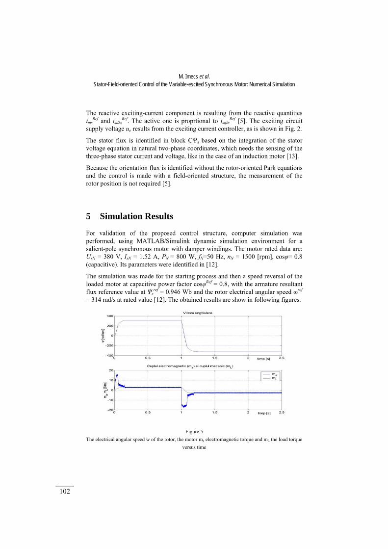
The simulation was made for the starting process and then a speed reversal of the loaded motor at capacitive power factor cosφRef = 0.8, with the armature resultant flux reference value at Ψs
ref = 0.946 Wb and the rotor electrical angular speed ωref
= 314 rad/s at rated value [12]. The obtained results are show in following figures.
Figure 5
The electrical angular speed w of the rotor, the motor me electromagnetic torque and mL the load torque versus time
Magyar Kutatók 7. Nemzetközi Szimpóziuma 7th International Symposium of Hungarian Researchers on Computational Intelligence
103
In Figs. 5 and 6 it can be observed an adequate response of the control system.
Figure 6
The mechanical characteristics of the load and motor under dynamic operation corresponding to Fig. 5
The reference value of the stator-field-oriented longitudinal armature reaction (isdλs i.e. the direct component of the armature current) is imposed with negative sign in order to determine a capacitive armature current [12].
In Fig. 7 a sudden variation of the exciting current can be observed during the starting, that may be caused by the exciting current control loop, which is very fast and the flux achieves rapidly its imposed reference value, consequently it determines a high acceleration of the motor [12].
Figure 7
The exciting current versus time
M. Imecs et al. Stator-Field-oriented Control of the Variable-escited Synchronous Motor: Numerical Simulation
104
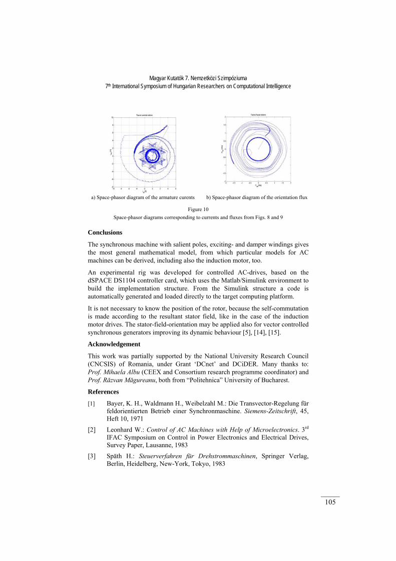
In Figs. 8 and 9 it can be observed the increase of the frequency at the motor starting and then, near moment 1s, change of the sequence when the speed reversing is realized.
Figure 8 The armature three-phase currents
Figure 9 The orientation flux in the three phases of the motor
Magyar Kutatók 7. Nemzetközi Szimpóziuma 7th International Symposium of Hungarian Researchers on Computational Intelligence
105
a) Space-phasor diagram of the armature curents b) Space-phasor diagram of the orientation flux
Figure 10 Space-phasor diagrams corresponding to currents and fluxes from Figs. 8 and 9
Conclusions
The synchronous machine with salient poles, exciting- and damper windings gives the most general mathematical model, from which particular models for AC machines can be derived, including also the induction motor, too.
An experimental rig was developed for controlled AC-drives, based on the dSPACE DS1104 controller card, which uses the Matlab/Simulink environment to build the implementation structure. From the Simulink structure a code is automatically generated and loaded directly to the target computing platform.
It is not necessary to know the position of the rotor, because the self-commutation is made according to the resultant stator field, like in the case of the induction motor drives. The stator-field-orientation may be applied also for vector controlled synchronous generators improving its dynamic behaviour [5], [14], [15].
Acknowledgement
This work was partially supported by the National University Research Council (CNCSIS) of Romania, under Grant ‘DCnet’ and DCiDER. Many thanks to: Prof. Mihaela Albu (CEEX and Consortium research programme coordinator) and Prof. Răzvan Măgureanu, both from “Politehnica” University of Bucharest.
References
[1] Bayer, K. H., Waldmann H., Weibelzahl M.: Die Transvector-Regelung für feldorientierten Betrieb einer Synchronmaschine. Siemens-Zeitschrift, 45, Heft 10, 1971
[2] Leonhard W.: Control of AC Machines with Help of Microelectronics. 3rd IFAC Symposium on Control in Power Electronics and Electrical Drives, Survey Paper, Lausanne, 1983
[3] Späth H.: Steuerverfahren für Drehstrommaschinen, Springer Verlag, Berlin, Heidelberg, New-York, Tokyo, 1983
M. Imecs et al. Stator-Field-oriented Control of the Variable-escited Synchronous Motor: Numerical Simulation
106
[4] Vauhkonen V.: A Cycloconverter-fed Synchronous Motor Drive having Isolated Output Phases. Proceedings of International Conference on Electrical Amchines, ICEM ’84, Lausanne, Switzerland, 1984
[5] Kelemen Árpád, Imecs Mária: Vector Control of AC Drives, Vol. 2: Vector Control of Synchronous Machine Drives. Ecriture Publisher, Budapest, 1993, ISBN 963 593 140 9
[6] Kelemen Á., Imecs M.: Analogy between DC- and Synchronous Machine for Field-oriented Control, Proceedings of Beijing International Conference on Electrical Machines BICEM ’87, China Academic Publishers, 1987
[7] Imecs M.: Vector Control Systems For Positioning of Induction Motors Fed By Static Converters (in Romanian), PhD Thesis, Supervisor Prof. Árpád Kelemen, Technical University of Cluj-Napoca, 1989
[8] Imecs Maria: How to Correlate the Mechanical Load Characteristics, PWM and Field-Orientation Methods in Vector Control Systems of AC drives, Bulletin of the Polytechnic Institute of Iassy, Tomul XLVI (L), Fasc. 5, Romania, pp. 21-30
[9] Imecs Maria, Trzynadlowski A. M., Incze I. I., Szabó Cs.: Vector Control Structures of the Tandem Converter Fed Induction Motor, IEEE Transactions on Power Electronics, March 2005, Vol. 20, Nr. 2, ITPEE8, pp. 493-501
[10] Imecs M., Szabó Cs., Incze I. I.: New Topology for Sine-Wave Current Filtering of Induction Motor Drives Fed by Tandem Frequency Converter, Acta Electrotehnica, Cluj-Napoca, Romania, Volume 44, Number 3, 2004, pp. 145-150, ISSN 1224-297
[11] Kelmen A., Imecs M.: Mathematical Model and Digital Simulation of a Current-Coverter Fed Synchronous Motor. ICEM ’84, Lausanne, 1984
[12] Szabó Csaba: Implementation of Scalar and Vector Control Structures for Synchronons Motors (in Romanian), PhD Thesis, Supervisor Prof. Maria Imecs, Technical University of Cluj-Napoca, Romania, 2006
[13] Incze I. I.: Implementation of Scalar and Vector Control Structures for Induction Motors (in Romanian), PhD Thesis, Supervisor Prof. Maria Imecs, Technical University of Cluj-Napoca, Romania, 2004
[14] Kelmen A., Imecs M.: Procedure and Driving Device for Unitary Automatic Vector Control of the Active and Reactive Power of Synchronous Generators by Means of Frequency and Voltage Regulation (In Romanian) Patent of Invention Nr. 104278/30.10.1989, Romania
[15] Kelmen A., Imecs M.: Vector Control System for Frequency and Voltage of Synchronous Generators. Proceedings of International Conference on Electrical Machines, ICEM ‘90, Cambridge, Massachusetts, USA, 1990