Abstract—This paper proposes an improved decoupling scheme of stator flux-oriented control for three-phase induction motor. The simulation software used in this paper is MATLAB Simulink®. The result of the simulation indicates that this stator flux-oriented control can control the speed of the rotor angle and stator magnetization current successfully. The angular velocity of 120 rad/s achieved by settling time 2 seconds in critically-damped response and steady-state error 0.083%. The controller can overcome the external disturbance in the form of load torque of 5 Nm which has been simulated in this paper. The proposed stator voltage decoupling scheme which is used in this simulation is correct and become one of success factor of this control method.
Keywords-Induction Motor;SFOC; Decoupling Model; Stator Flux Model
I. INTRODUCTION
Induction motor is a type of AC motor that is often used by industrial field because it has good self-starting ability, simple structure, low cost of production and maintenance, and reliable [1]. One of the problem of induction motor is that it is difficult to control. Further developments of power electronics and microelectronics open the issue of research and development of induction motor vector control. Some vector controlling techniques that have been proposed before are divided into two, direct vector control and indirect vector control based on field orientation vector. Direct vector control obtains the field orientation vector by using the quantity of stator terminal. In the other hand, indirect vector control obtains the field orientation vector by using slip frequency of machine.
Stator flux-oriented control of induction motor is a type of direct vector control because it uses the quantity of stator terminal. This method has several parts that can be developed, such as decoupling scheme and stator flux model.
This paper describes the simulation of three phase squirrel cage induction motor speed control based on stator flux orientation by using the proposed decoupling stator voltage scheme.
II. IM MODEL AND DRIVE OPERATING PRINCIPLE
To simulate the three-phase squirrel cage induction motor control, the dynamic model of induction motor is needed. The fundamental behavior of squirrel cage induction motor is usually based on a set of dynamical equations that can be
expressed in different reference frame. In this section, the induction machine model is defined by the stator currents and stator flux as state variables in the stationary α-β reference frame. The dynamic model that is used in this paper is same as in [4]. The following is the dynamic model of three phase squirrel cage induction motor: = ( − −− − )
(1)
= ( − −− − )
(2)
= −( − −− − )
(3)
= −( − −− − )
(4)
= 1− (5)
Where: , = Stator voltages α-β in stationary
reference frame (Volt) , = Stator currents α-β in stationary
reference frame (Volt)
= Stator resistance (Ohm)
= Rotor resistance (Ohm)
= Stator inductance (Henry)
= Rotor inductance (Henry)
= Mutual inductance (Henry)
= Rotor angle speed (rad/s)
= Number of pole pair
Figure 1 below shows the three-phase squirrel cage induction motor speed control based on stator field orientation block diagram with the proposed control algorithm.
Proceeding of EECSI 2018, Malang - Indonesia, 16-18 Oct 2018
Figure 1 The three phase squirrel cage induction motor speed control based on stator field orientation block diagram
The algorithm inputs are reference rotor speed ∗and stator
magnetizing current ∗. Main control loop consists of the speed IP regulator, the magnetizing current PI regulator, and the current controllers. The feedback signals of stator magnetizing current and rotor speed , needed for closed-loop control are provided by stator flux model and rotor speed sensor, respectively. The stator flux model utilizes the stator currents and voltages as the input variables. Decoupling scheme that is proposed in this paper is described later.
III. IMPROVED DECOUPLING SCHEME AND STATOR FLUX
MODEL
A. Improved Decoupling Scheme
Decoupling scheme is a very important part of stator field oriented control. By using an appropriate decoupling scheme, the torque component and flux component can be separated and controlled respectively. In modelling the decoupling equation of induction motor stator voltage, it can be started from the equation of rotor voltage as in the following equation (6) = (− )( )
(6)
In equation (6) there is still a rotor current component, where the component mus be eliminated by substituting equation (18) into equation (6), and by assuming the rotor coil of the squirrel cage type is a short circuit then = 0, then a new rotor voltage equation is obtain as follows.
0 = | | − | | − | | −
(7)
Then, it is necessary to separate the real and imaginary components from equation (7) to obtain the equation (8) and (9) as follows
| | | | = − (8)
| | − = (9)
To obtain the stator voltage equation in the x and y axes it is necessary to substitute equations (22) and (10) into equations (8) and (9) | | = −
(10)
The three phase squirrel cage induction motor stator voltage equation in the x and y axesarepresented by the following equations (11) and (12)
= ′ ′′ − −− ′ ′
(11)
= ′ ′ ′ ′ (12)
In equations (11) and (12), it can be seen that there is coupling between the x and y components that can cause nonlinearity. Therefore, we can obtain the stator voltage decoupling equation as in the following equations (13) and (14)
= ′ ′ − (13)
= − ′ (14) The given stator voltage must satisfy the following equations (15) and (16) ∗ = (15)
∗ = (16)
Figure 2 below is the decoupling scheme proposed in this paper.
Proceeding of EECSI 2018, Malang - Indonesia, 16-18 Oct 2018
250
Figure 2 The improved decoupling scheme of three phase squirrel cage
induction motor stator voltage
B. Stator Flux Model
Stator flux model is one of the important parts of stator field oriented control of induction motor. By using the appropriate stator flux model, the calculation results of the parameters required in the control objective will be more accurate and precise. In an attempt to model the statof flux model of three-phase squirrel cage induction motor, it can be started from the three phase squirrel cage induction motor stator voltage as in the following equation (17) =
(17)
In equation (17), there is still a rotor current component. As it is known that in the three phase squirrel cage induction motor, rotor current component is very difficult to obtain. Therefore, the rotor current component of the equation (17) must be eliminated by substituting the rotor current equation shown in equation (18) = | | − (18)
Substituting equation (18) into equation (17), equation (19) is obtained as the stator voltage equation of the three phase squirrel cage induction motor in which no rotor current component is present. = | | | | (19)
Then, simplify equation (19) to its real and imaginary component and make it in the x-y stator current equation as in the following (20) and (21) equations.
= − | |
(20)
= − | |
(21)
To obtain the equation of stator flux model, equation (20) and (21) must be processed to obtain the stator flux model as follows. | | = −
(22)
= 1| | − (23)
= (24) =
(25)
Equations (22) – (25) are the basic equations of stator flux model which are used to calculate the parameters of the three phase squirrel cage induction motor used for control. The representation of the stator flux model in a block diagram can be made from equations (22) – (25). Figure 3 below shows a diagram of the stator flux model of three phase squirrel cage induction motor that is used in this research.
Figure 3 Stator flux model of three pase squirrel cage induction motor
IV. SIMULATION RESULT
The proposed simulation of three phase squirrel cage induction motor in this paper is simulated by C-MEX S-Function block diagram in MATLAB Simulink. The simulation was run for 10 seconds. Figure 4 below is the simulation block diagram in MATLAB Simulink.
Figure 4 CMEX S-Function Simulation Diagram in MATLAB Simulink
Proceeding of EECSI 2018, Malang - Indonesia, 16-18 Oct 2018
251
The test was done within two condition testing. For the first segment, system was tested by stating the load torque as 0 Nm, the stator magnetizing current as 1.45 A and the rotor speed as 120 rad/s. This is shown as a no load testing. The second segment was tested by stating the load torque as 5 Nm after 5 seconds of the simulation, the stator magnetizing current as 1.45 A and the rotor speed as 120 rad/s. This is shown as load testing.
The parameter and rating of a three-phase induction motor that is used in this simulation shown in the table below
Table 1 Induction Motor Parameters and Ratings
Vrated 220 V Rr 1.7979 Ω
Irated 5.1 A Ls 0.4633 H
Nrated 1433 rpm Lr 0.4633 H
Rs 2.4057 Ω Lm 0.4531 H
A. No Load Testing
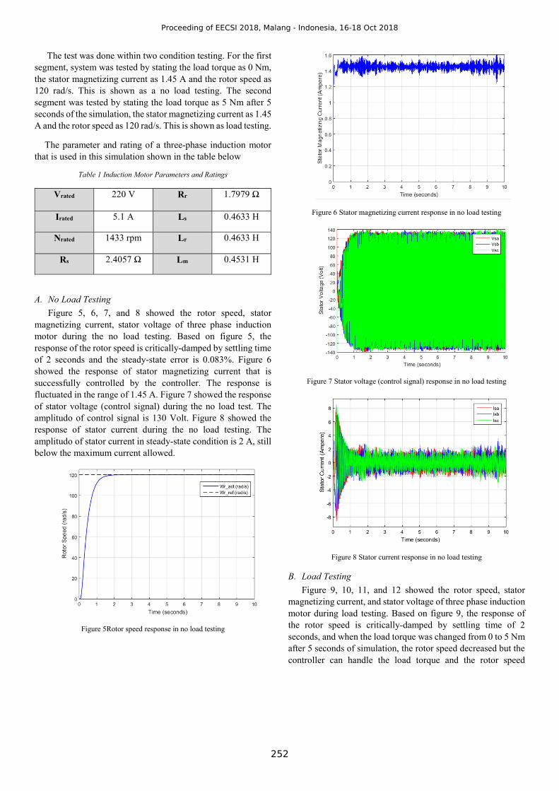
Figure 5, 6, 7, and 8 showed the rotor speed, stator magnetizing current, stator voltage of three phase induction motor during the no load testing. Based on figure 5, the response of the rotor speed is critically-damped by settling time of 2 seconds and the steady-state error is 0.083%. Figure 6 showed the response of stator magnetizing current that is successfully controlled by the controller. The response is fluctuated in the range of 1.45 A. Figure 7 showed the response of stator voltage (control signal) during the no load test. The amplitudo of control signal is 130 Volt. Figure 8 showed the response of stator current during the no load testing. The amplitudo of stator current in steady-state condition is 2 A, still below the maximum current allowed.
Figure 5Rotor speed response in no load testing
Figure 6 Stator magnetizing current response in no load testing
Figure 7 Stator voltage (control signal) response in no load testing
Figure 8 Stator current response in no load testing
B. Load Testing
Figure 9, 10, 11, and 12 showed the rotor speed, stator magnetizing current, and stator voltage of three phase induction motor during load testing. Based on figure 9, the response of the rotor speed is critically-damped by settling time of 2 seconds, and when the load torque was changed from 0 to 5 Nm after 5 seconds of simulation, the rotor speed decreased but the controller can handle the load torque and the rotor speed
Proceeding of EECSI 2018, Malang - Indonesia, 16-18 Oct 2018
252
increased back to 120 rad/s.Figure 10 showed that the response of stator magnetizing current in the load testing is same as in the no load testing. Figure 11 showed the response of control signal (stator voltage) during the load testing. The amplitudo of control signal increased from 130 Volt to 150 Volt after the load torque was applied to the system. Figure 12 showed the response of stator current during load testing. The amplitudo of stator current increased from 2 A to 4 A after the load torque was applied to the system.
Figure 9 Rotor speed response in load testing
Figure 10 Stator magnetizing current response in load testing
Figure 11 Stator voltage (control signal) response in load testing
Figure 12 Stator current response in load testing
V. CONCLUSION
The result of the simulation indicates that this stator flux oriented control with improved stator voltage decoupling scheme is capable to control both speed of the rotor angle and stator magnetization current successfully. The angle velocity of 120 rad/s achieved by settling time 2 seconds in critically-damped response and steady-state error 0.083%. The controller can overcome the external disturbance in the form of load torque of 5 Nm which has been simulated in this paper.The proposed stator voltage decoupling scheme which are used in this simulation is correct and also become one of success factor of this control method.
ACKNOWLEDGMENT
This research is funded by Universitas Indonesia research grant of the Publikasi Internasional Terindeks untuk Tugas Akhir Mahasiswa UI (PITTA) 2018 Nomor: 2439/UN2.R3.1/HKP.05.00/2018
REFERENCES
[1] M. Baishan and J. Feng, "Study on Stator Flux Oriented
Sensorless Induction Motor Control System," IEEE, pp. 758-762, 2014.
[2] S. Lee, G. Park and M. Jung, "Sensorless Stator Flux Oriented Control of Induction Motors using PLPF with Flux Error Compensator," IEEE, 2014.
[3] V. Staudt and A. Steimel, "Stator-Flux-Oriented Control for Traction Drives," IEEE, pp. 779-786, 2015.
[4] F. Yusivar dan S. Wakao, “Minimum Requirements of Motor Vector Control Modeling and Simulation Utilizing C MEX S-function in MATLAB/SIMULINK,” IEEE, 2001.
[5] J. Cherian and J. Mathew, "Parameter Independent Sensorless Vector Control of Induction Motor," IEEE, 2012.
Proceeding of EECSI 2018, Malang - Indonesia, 16-18 Oct 2018


![INDUCTION MOTOR DRIVE BASED ON THE STATOR FLUX …vukosavic.etf.bg.ac.rs/djs1.pdfThe concept of Direct Torque Control (DTC) [1]-[3] algorithms for the induction motor was introduced,](https://static.documents.pub/doc/80x56/5f70317d3425cd0d46083582/induction-motor-drive-based-on-the-stator-flux-the-concept-of-direct-torque-control.jpg)


