274
IAEA-TECDOC-CD-1614 Status and Prospects for Gas Cooled Reactor Fuels Proceedings of two IAEA meetings held in June 2004 and June 2005 April 2009

IAEA-TECDOC-CD-1614
Status and Prospects for Gas Cooled Reactor Fuels
Proceedings of two IAEA meetings
held in June 2004 and June 2005
April 2009

The originating Section of this publication in the IAEA was:
Nuclear Fuel Cycle and Materials Section International Atomic Energy Agency
Wagramer Strasse 5 P.O. Box 100
A-1400 Vienna, Austria
STATUS AND PROSPECTS FOR GAS COOLED REACTOR FUELS
IAEA, VIENNA, 2009
ISBN 978–92–0–152809–4
ISSN 1684–2073 © IAEA, 2009
Printed by the IAEA in Austria April 2009

FOREWORD
Recently, efforts to develop high temperature gas cooled reactors with an aim to building futuristic
nuclear energy systems with advanced nuclear fuel cycles in the context of the Generation IV
International Forum have increased significantly. In addition, several development projects are
ongoing, focusing on the burning of weapons grade plutonium, including civil plutonium and other
transuranic elements using the ‘deep-burn concept’, or ‘inert matrix fuels’, especially in the form of
coated particles in gas cooled reactor systems. There is also considerable global interest in developing
‘nuclear hydrogen’ energy systems using high temperature gas cooled reactors. Apart from these
developments, the value of preserving the large technology base developed in Germany, the United
Kingdom and the United States of America, as well as information developed in other countries, has
also been a subject of interest to the IAEA.
At the second annual meeting of the ‘technical working group on nuclear fuel cycles options and spent
fuel management’ (TWG-NFCO), held in Vienna from 28–30
May 2003, it was recommended to hold
a technical meeting on Current Status and Future Prospects of Gas Cooled Reactor Fuels. The meeting
should cover the technological progress that has been made in the last three years and plan future
fabrication and qualification facilities for GCR/HTR fuel. TWG-NFCO considered it timely that this
progress should be presented and discussed in the interested community. Recognizing the numerous
activities being pursued in many Member States, the IAEA convened the technical meeting on this
topic in June 2004 in Vienna. Consequently, an update meeting was held in June 2005, which was
hosted by the Kharkov Institute of Physics and Technology of Ukraine to review and integrate the
latest developments. This publication combines the results of the technical meeting of June 2004 and
the meeting of June 2005. The proceedings presented here contain 25 in depth papers on the following
topics: overview of recent developments in nine countries; power and limitations of coated particle
fuel modelling; Fuel performance technology; and novel ideas/applications/disposal questions. The
meeting critically reviewed advanced fuel designs, including conventional ones, fabrication
technology, quality assurance/quality control of fuel, fuel irradiation qualification, fuel performance,
fuel modelling for transport and performance and overall fuel cycle issues.
The IAEA is grateful to the experts who contributed to this publication. M.B. Tyobeka of the Division
of Nuclear Power gave a critical review of thispublication. The IAEA officer responsible for this
publication was H.P. Nawada of the Division of Fuel Cycle and Waste Technology.

EDITORIAL NOTE
This CD-ROM has been prepared from the original material as submitted by contributors. Neither the IAEA nor its Member States assume any responsibility for the information contained on this CD-ROM. The use of particular designations of countries or territories does not imply any judgement by the publisher, the IAEA, as to the legal status of such countries or territories, of their authorities and institutions or of the delimitation of their boundaries. The mention of names of specific companies or products (whether or not indicated as registered) does not imply any intention to infringe proprietary rights, nor should it be construed as an endorsement or recommendation on the part of the IAEA.

CONTENTS
Summary
Session 1: Country overview
Overview of the DOE advanced gas reactor fuel development and qualification program and gas
reactor R&D
M.A. Feltus The current state of the HTGR core component fabrication technologies in the Ukraine
and some properties of materials and products
M.P. Odeychuk, V.F. Zelenskiy, V.A. Gurin, V.K. Yakovlev Progress in the PBMR fuel development laboratories
F. Venter Overview on HTR coated particle fuels development in Russia
A.S. Chernikov, S.D. Kurbakov Present status of HTTR project in Japan
K. Sawa, S. Fujikawa, M. Ogawa Research and development activities on high temperature reactor fuel in Indonesia
Suwardi, Sudarmadi, Karyono Hs Coated particle fuels for high temperature reactors – Indian programme
V.N. Vaidya CEA and AREVA R&D on HTR fuel technology
P. Guillermier, M. Phélip Overview of R&D activities of HTR fuel in China
Tang Chunhe Session 2: Coated particle fuel modelling
TRISO particle fuel performance code benchmarking activities performed under
the IAEA 6th coordinated research programme on advances in HTR fuel technology
M. Phelip, I. Kadarmetov, D. Petti, H. Nabielek, K. Verfondern, T. Abram Can we predict coated particle failure? A conversation on CONVOL, PANAMA
and other codes
H. Nabielek, K. Verfondern, H. Werner Some fundamental considerations pertaining to modelling the mechanical behaviour
of coated fuel particles during irradiation
D.G. Martin Fuel chemistry and co formation in gas cooled reactor fuel
U. Colak, O.Ö. Gülol High temperature materials – The challenge for future advanced gas cooled reactors
W. Hoffelner
Session 3: Fuel performance and technology
Post-irradiation testing of HTR-fuel elements under accident conditions
H. Kostecka, J. Ejton, W. De Weerd, E.H. Toscano Prediction of metallic fission product release behavior in the 220 MW(TH)
FAPIG-HTGR during normal operation and core heatup accident
K. Verfondern, H. Mikami, F. Okamoto TRISO-coated particle fuel phenomenon identification and ranking tables (PIRTS)
for fission product transport due to manufacturing, operations and accidents
S.D. Rubin
Post-irradiation examination of HTR-10 fuel
Tang Chunhe, Fu Xiaoming, Zhu Junguo, K. Koshcheev, A.V. Kozlov , O.G. Karlov, Y.G. Degaltsev Research and development program of HTGR fuel in Japan
K. Sawa, S. Ueta, T. Iyoku Session 4: Novel ideas and application related to coated particle fuel
A deep burn fuel management strategy for the transmutation of light water reactorswaste in the gas
turbine–modular helium reactor
A. Talamo, W. Gudowski Fuel requirements for the advanced high–temperature reactor: Graphite coated–particlefuel and molten
fluoride salt coolant
C.W. Forsberg, M.A. Feltus The international GT–MHR fuel development program
N. Kodochigov, Yu.P. Sukharev, N. Ponomarev-Stepnoy, Yu. Degaltsev, V. Novikov, I. Kadarmetov, V. Makarov, V. Sulaberidze, A. Chernikov, D. McEachern, R. Noren Images of HTGR fuel cycle and view points important
Y. Tsuchie State of the gas turbine–modular helium reactor development
N.G. Kodochigov, Yu.P. Sukharev, A.G. Chudin
List of participants

SUMMARY
Currently there is increased interest in gas cooled reactor (GCR) technology owing to a growing recognition of the potential of GCRs; namely a) improved inherent safety attributes, b) high efficiency, c) small modular type, e) environmentally acceptable, and f) future application of process heat such as hydrogen production. Gas cooled reactors have been built in China, France, Germany, the United States of America, and the United Kingdom for the purpose of reactor research as well as demonstration of power generation. The electricity company ESKOM (Electricity supply commission), and the Pebble bed modular reactor (PBMR) of South Africa are pursuing the building of a 165 MW(e) pebble-bed demonstration power plant. In the context of building futuristic nuclear fuel cycles for Generation IV international forum (Gen-IV) and RAPHEL (Reactor for process heat, hydrogen and electricity generation), there are increased efforts in developing gas cooled high-temperature reactors. In addition there are several developmental programmes that focus on burning both weapon-grade and civil plutonium and other transuranic elements using ‘deep-burn concept’ or ‘inert matrix fuels’ especially in the form of coated particles in gas cooled reactor systems. There is also considerable global interest in developing ‘nuclear hydrogen’ energy systems using high temperature gas cooled reactors. High temperature gas cooled reactors (HTGRs) have demonstrated their high temperature process heat capabilities by attaining reactor outlet coolant temperatures up to 950°C. the Russian Federation and the USA have a project to develop a modular HTGR to burn excess plutonium which is no more required for the defence programme. Development of fast reactor with gas coolant is also under consideration for the future generation reactors in France and the Gen-IV. Apart from these developments, preserving the large technology base developed in Germany, the United Kingdom and the USA, as well as information developed in other countries, is a subject of global interest. In addition to dedicated GCRs, several materials test reactors for testing HTGR fuels and materials were utilized globally; for example: Belgian reactor 2 (BR2), SILOE1 (a pool type research reactor located in Grenoble, France), research reactor DIDO1 in Germany, Japan materials testing reactor (JMTR), high flux reactor (HFR) in the Netherlands, the IVV-2M reactor (a pool-type water cooled and -moderated reactor with 15 MW•th in the Russian Federation), South African research reactor (SAFARI), Research reactor No 2 (R21) in Sweden and high flux isotope reactor & advanced test reactor (HFIR & ATR) in the USA. The success of advanced HTGRs depends on the safety and quality of its fuel, namely the coated particle fuel. Considering the numerous activities being pursued in many Member States and the suggestion of the second annual meeting on Nuclear Fuel Cycle Options and Spent Fuel Management (TWG-NFCO), the IAEA convened a technical meeting (TM) on Current Status and Future Prospects of Gas Cooled Reactor Fuels from 7 to 9 June 2004 in Vienna. The meeting was attended by 31 experts from 16 Member States and one expert from an international organization, Institute for transuranium elements/European Commission (ITU/EC). Subsequent to the technical meeting in Vienna, an update meeting was held in June 2005 in Kharkov, Ukraine, which was hosted by the National Science Centre of the Kharkov Institute of Physics and Technology (NSC-KIPT), to review and integrate the latest developments into the current document. Twenty-three experts attended the update-meeting from 10 Member States. The proceedings of both meetings generated 25 in-depth papers which were presented in four technical sessions; I) Country overviews; II) Coated particle fuel modelling; III) Fuel performance and technology; and IV) Novel ideas and application related to coated particle fuel.
___________________________________________________________________________ 1 indicates currently shut down.
SESSION-1: COUNTRY OVERVIEW
Nine papers were presented in the first session which was devoted to country overviews of the development of coated particle fuel and other associated components in developing gas cooled reactors. To ensure the performance of GCR fuel from the standpoint of safety, reliability, and economics, it is necessary to rely not only on proper materials selection and design but also on manufacture of a consistent high quality product. Several proven large-scale processes are currently available for the production of coated particles. Fuel technology for gas cooled reactors has been demonstrated, but has not yet been commercialized. General Atomics Company (GA) from the USA and NUKEM from Germany, mastered this coated particle fuel technology, but stopped manufacturing the fuels since 1980. Subsequently, the ‘Institute of nuclear engineering technology’ (INET) at Tsinghua University, China and ‘Nuclear energy corporation of South Africa’ (NECSA), South Africa as well as ‘Japan atomic energy research institute’ (JAERI,2) and ‘nuclear fuel industries (NFI) from Japan have pursued the development of the fuels. The first paper of this session illustrated the US DOE ‘advanced gas reactor fuel development and qualification’ (AGRFDQ) program that supports the ‘Generation IV very high temperature gas reactor next generation nuclear plant’. The objectives and current status of the AGRFDQ programme were described, as well as the future plans for tri-isotropic (TRISO) fuel research and development and irradiation capsule tests at the Idaho national engineering and environmental laboratory (INEEL). The paper from NSC-KIPT, Ukraine described the status of work on spherical pyrocarbon (PyC)-bound fuel elements for HTGRs, with the fuel based on uranium dioxide, uranium carbonitride and thorium dioxide at NSC-KIPT. It describes the basic technological schemes of production of fuel microspheres, coated particles and spherical fuel elements. Consideration is given to some special features of fabricating carbon-graphite materials and products by volume gas-phase impregnation of porous substances with pyrocarbon. Results of tests of the basic characteristics of spherical fuel elements and their components as well as the materials and products with a pyrocarbon binder, including irradiation conditions are discussed. An overview of the progress made in the ‘fuel development laboratories' at the ‘pebble bed modular reactor’ (PBMR) was provided in the paper from NECSA, South Africa. The establishment of a PBMR-FDL at NECSA is well advanced. The laboratory includes all the facilities required to manufacture uranium dioxide kernels, TRISO coated particles and PBMR spherical fuel elements in accordance with specifications. It also has a quality control (QC) laboratory to perform the chemical, physical and dimensional tests necessary to control the manufacturing processes and to verify conformance to specified requirements. In advance of construction and start-up of the PBMR fuel plant, the latest German high temperature reactor TRISO fuel manufacturing technology has been reproduced on laboratory scale. The purpose of the laboratory is to develop and validate the QC methods, select and qualify material suppliers, gain experience and understanding of the manufacturing processes, and train staff for the PBMR fuel plant. Development of the manufacturing and QC processes progressed significantly. About 50 kg of UO2 kernels were produced for QC testing and trial runs in the existing laboratory chemical vapour deposition (CVD) coater. A production–scale CVD coater (5 kg UO2 charge) was designed. The production–scale coater is representative of the coaters to be installed in the PBMR pilot fuel plant. Experience of manufacturing of the first uranium-containing fuel spheres is described. Approximately 90 % of experimental work required to establish the main product QC tests required for PBMR fuel has been completed. After commissioning and testing of the production–scale coater, the laboratory fuel manufacturing facilities will be a good simulation of the processes to be applied in the PBMR pilot fuel plant. Investigations in the field of TRISO coated particle fuels development for Russian HTGRs, with pebble bed core were presented. Requirements for UO2 kernels with a 500 μm diameter and for
___________________________________________________________________________ 2 renamed as Japan atomic energy agency; JAEA after 2007.

Page 3
coatings on them as well as the achieved characteristics of coated particle fuels are discussed in the paper. Requirements for coated particle fuels based on kernels of 200 μm in diameter for modular high temperature reactors (HTRs) with prismatic cores are also described. It provides the first results of investigations on manufacture of such coated particle fuels on laboratory scale. An outline of the Japanese HTGR project; history, operation experiences including recent achievement of 950 °C outlet temperature are presented. Progress of the introduction of hydrogen production technology is also presented. Questions regarding the irradiation program and capability in the High Temperature Engineering Test Reactor (HTTR) and other related issues are addressed. A compact high temperature reactor (CHTR) is proposed to be taken up soon in India. This reactor uses coated particle fuel in the form of compacts packed in tubes with BeO as moderator and Pb-Bi as coolant with highest coolant temperatures of 950 °C. An internal gelation process has been studied in Indian laboratories for making UO2, UC, UC2, (U, Pu)O2 microspheres and a flow-sheet for production and disposal of aqueous waste has been developed. Work on coating technology has started. After studying high temperature reactor (HTR) technology and its potential application in Indonesia, the Indonesian HTR team expanded the scope of its program studies to cover: reactor technology, safety, environment, coal liquefaction, desalination, instrumentation and control, and the HTR fuel cycle. Research on HTR fuel was designed to be performed in at least two centres. Yosyabark nuclear centre is studying coated particle fuel fabrication and Serpong nuclear centre is studying HTR fuel element fabrication, irradiation and post-irradiation examinations (PIE), and HTR-Fuel modelling. Over the past 6 years, with a limited budget and equipment, 15 publications related to HTR fuel study, both bibliographic and experimental, have been produced by the HTR team. The publications cover two areas: the sol-gel process for kernel production and modelling for safety of spherical fuel failure. The probability of coating failure during irradiation has been evaluated by using a fission product code and an analytical method. Research and development on HTR fuel technology in ‘Commissariat à l’Energie Atomique’ (CEA) and French nuclear industry named AREVA were summarized. In the framework of the French HTR programme, the CEA in relationship with AREVA and FRAMATOME-ANP (now called as AREVA NP) conducts R&D projects on HTR fuel. These projects are aimed at: • Mastering the UO2 TRISO particle fuel fabrication technology; • Irradiating new fuels coming from French new facilities; • Performing post-irradiation examinations on these fuels; and • Developing a simulation code, this will be supplied with this programme. These four topics constitute the basis of a fuel development and qualification programmes. The objective of this programme is the design and the qualification of a fuel which will fulfil the very high temperature reactor (VHTR) requirements. A review of existing technologies and initial laboratory-scale work has been conducted with the aim of recovering the know-how of the HTR coated particle manufacture. In parallel, a future experimental manufacture line named GAÏA has been designed and is under construction at CEA Cadarache to produce HTR TRISO particle fuel representative of what should be an industrial fuel. This fuel will be irradiated at the French material testing reactor named OSIRIS at CEA-Saclay in France. The foreseen fuel irradiation programme named SIROCCO will provide data on fuel performance under irradiation, support fuel process development, qualify fuel under normal operating, non-operating and accidental conditions and support development and validation of fuel performance and fission product transport models and codes. PIE will be performed in the active fuel examination facility named LECA at Cadarache, France. In parallel, a simulation code named ‘advanced thermal mechanical analysis software’ (ATLAS) is under development with

the objectives to quantify, by a statistical approach, the failed particle fraction and the fission product released fraction of a loading in normal and accidental conditions.
An overview of the previous work at the ‘Institute of nuclear energy technology’ (INET), of Tsinghua University, Peoples’ Republic of China, current tasks and planned activities in coated particle fuel development was presented. The fabrication process for the HTR-10 spherical fuel developed by INET includes UO2 kernel preparation through the modified gel precipitation process, PyC and silicon carbide (SiC) coatings on the UO2 kernel surface by chemical vapour deposition and the manufacture of the spherical fuel element by the quasi-isostatic process. The fabrication of HTR-10 fuel had been finished before July 2002. Over 20 000 spherical fuel elements for HTR-10 have been successfully fabricated. The irradiation testing of 4 spherical fuel elements, sampled randomly from the first and second product batches respectively, started on 13 July 2000 in the Russian IVV-2M reactor. This testing was finished in February 2003. Maximum burnup and fast neutron fluence of the irradiated fuel elements reached 107 000 MWd/tU and 1.3×10²¹ n/cm2 at a constant temperature of 1000 °C, respectively. The performance of the fabricated fuel elements meets the design requirement of HTR-10 fuel. INET plans to build a prototype HTR (HTR-PM) with output of 100 MW(e) in People’s Republic of China. Therefore further activities will be conducted to provide technical support for the fuel plant, and to make efforts to advance HTGR fuel technology such as study of the oxidation resistant coating for the matrix graphite of the fuel element and reactor reflector graphite, study of zirconium carbide (ZrC) coating instead of SiC coating of TRISO coated fuel particles and study of the coated particle performance modelling. SESSION-2: COATED PARTICLE FUEL MODELLING Five papers on coated particle fuel modelling encompassing several aspects of fuel were presented. Sophisticated design models are being developed that take into account a multiplicity of factors including particle dimension, internal gas pressure and irradiation-induced dimensional change and creep of PyC coatings. These models are utilized in understanding the mechanical behaviour of particles, failure analysis of particles, temperature analysis within particles, for both pebble and block fuels, as well as fission product release behaviour.
A key part of the IAEA 6th Coordinated Research Program on Advances in HTGR Fuel Technology includes benchmarking of fuel performance models under normal and accident conditions. The normal operation and accident behaviour benchmarks have been structured in two phases. In the first phase, a series of simplified analytical benchmarking problems have been established for both normal and accident conditions as a way to “calibrate” all of the codes and/or models. In the second phase, the codes and/or models will be used to calculate fuel behaviour in past and future irradiation experiments and heating tests. Current participants in the benchmark include England, France, Germany, the Russian Federation and the USA. The paper presents a status of this international code benchmarking activity.
A detailed paper on prediction of coated particle failure with models such as CONVOL (Convolution Faltungsintegral), PANAMA (Particle modelling according to Nabielek and Martin) and other codes was presented.
Some consideration of the fundamentals pertaining to modelling the mechanical behaviour of coated particle fuel (CFP) during irradiation considering kernel-coating mechanical interaction is presented in the paper from the United Kingdom.
Typical internal gas pressures for CFPs were calculated as a function of temperature and burnup and presented in a study from the Turkish Atomic Energy Authority. Fission product concentrations as a function of burnup were calculated using the well-known depletion code ORIGEN. The amount of pressure build-up was estimated using two components; noble gas contribution from fission products and CO contribution. CO formation is attributed to migration to the buffer layer of free oxygen

Page 5
released upon fission and not yet bound with any fission product. The results of this study are assessed in terms of coated fuel particle CFP integrity.
The availability of materials for near term VHTR-type plants with direct cycle He-turbine and high temperature hydrogen production was analyzed (reactor pressure vessel, internals, turbine and piping) in a presentation by Paul Scherer Institute (PSI), Switzerland. The current situation can be summarized as follows: Reactor pressure vessel (RPV)-temperature currently limited to 490 ºC (no creep accepted); SiC/C, C/C, SiC/SiC for control rod eventually feasible; no metallic materials for temperatures higher than 950 ºC and 6 years operation available and ASME codes still to be improved. Therefore, it is fair to say that VHTRs envisaged to be in operation within the next 15 years will most probably operate in a temperature regime of 900 ºC to 950 ºC. Nevertheless, new materials oxide dispersed strengthened (ODS) type steel materials, inter-metallics, super-plastic ceramics, refractory materials, fibber-reinforced materials) must be developed together with new design concepts for the time beyond 2017, preferentially in close collaboration with the gas cooled fast reactor (GFR) developments. SESSION-3: FUEL PERFORMANCE AND TECHNOLOGY Continued use of very sophisticated and sensitive characterization techniques should not only improve the understanding of the microstructure but also should provide more insight into the influence of the deposition conditions, the resultant physical properties and the subsequent irradiation behaviour of coating layers. In general, statistical and design criteria are established to ensure a very low probability of failure of coated particle fuel under all normal conditions and anticipated transients. The coating materials are specified to ensure that particle performance is not limited by the properties of coating materials themselves. The general factors that limit coated particle fuel performance can be identified as: coating layer rupture owing to fuel swelling or internal pressure build-up viz., CO gas build-up or temperature increase at transient condition or anisotropic shrinkage of coating layer; or chemical interaction between the coating layer and fission product or kernel migration (known as Amoeba effect). Several HTR fuel irradiation tests are being carried out with the following objectives: • Data on fuel performance under irradiation; – In-pile gaseous fission product release; – End-of-Life metallic fission product release; – End-of-Life fuel condition & material properties; • Dimensional, density changes; • Particle & matrix physical condition (metallography); • Chemical attack and fission product location; • Irradiated specimens for post-irradiation testing. Previously defined good fuel is now measured by different standards from the seventies: while 3x10⁻⁴ of initial free heavy metal was acceptable for THTR, today an order of magnitude below this value is insisted upon. Half a percent of particle failure at the end-of-irradiation by another ancient standard, but today is not acceptable even for the most severe accidents.
A comprehensive description of the installation of the ‘cold finger apparatus’ (KÜFA) at the Institute for transuranium elements, European Commission together with the calibration procedures and the future experimental programme for post-irradiation of HTR fuel elements under accident conditions is described in the first paper of this session.
The objective of the study from research centre Jülich (FZJ), Germany, is a first approach to assessing the metallic fission product release behaviour in the HTGR core of the ‘first atomic power industry

group’ FAPIG-HTGR using the methodology as was developed and recommended at FZJ. The computer codes FRESCO and PANAMA were applied to assess the release of the radiologically relevant fission products Cs-137, Sr-90, and Ag-110m from the FAPIG-HTGR during the fuel lifetime under normal operation and core heatup accident conditions. The results show that under the given thermal hydraulic boundary conditions, the release remains on a very low level for all radio-nuclides investigated, for the specified operating conditions of the reactor design considered and for the typical German reference spherical fuel element,
A comprehensive review of the IAEA’s safety related works on GCR was presented. The presentation encompassed the following subjects: IAEA Safety Standards; IAEA Publications Related to Accident Analysis viz.: Safety fundamentals, requirements and guides as well as points of interest in HTGR.
The motivation for the development of ‘particle fuel phenomenon identification and ranking tables’ (PIRT) and its planned uses in study of fission product transport, was presented by the USA Nuclear Regulatory Commission (US-NRC). Recently, the NRC has articulated six basic principles of evaluation model development and assessment. The first principle is to ‘determine the requirements for the evaluation model’. Central to this step is identification of the components, phenomena, physical processes, and parameters needed to evaluate event behaviour. This PIRT methodology can be used to support several important decision-making processes. For example, the information can be used to support either the definition of requirements for related experiments and analytical tools or the adequacy and applicability of existing experiments and analytical tools. This information is important because it is neither cost effective nor required to assess each feature of an experiment or analytical tool in a uniform fashion. The PIRT methodology brings into focus the phenomena that dominate, while identifying all plausible effects to demonstrate completeness. Each PIRT panel must determine the appropriate phenomenological levels to include in its list of identified phenomena. Insights into the levels to be included can often be derived by considering the data needs for analytical methods and the level at which experimental data are collected. Usually, there is no need to proceed further down the phenomenological hierarchy than: (a) the level at which physical processes are modelled with analytical methods; or (b) the level at which data, either direct or indirect, are acquired.
In the HTGRs, refractory CFPs are employed as fuel to permit high outlet coolant temperature. The HTTR employs TRISO coated particle fuel in the prismatic fuel assembly. Research and development on the HTTR fuel has been carried out over about 30 years in the following areas; in fuel fabrication technologies, fuel performance under normal operation, transient and accident conditions, fission product behaviour and so on. Furthermore, for upgrading of HTGR technologies, an extended burnup TRISO-CFP and an advanced type of CFP viz., ZrC-CFP in order to keep the integrity at higher operating temperatures has been developed. The present paper provides experiences and current status of research and development work for the HTGR fuel in the HTTR Project. Some of the questions that are examination are: selection of Br process for ZrC coatings, inspection methods for coated ZrC.
The final paper in this session introduced the results of the post irradiation examination of HTR-10 fuel at the INET in Peoples’ Republic of China. The irradiation testing of fuel for HTR-10 in the Russian test reactor, IVV-2M, was finished in February 2003. Maximum burn up and fast neutron fluence of the irradiated fuel elements reached 107 000 MWd/tU and 1.3x10²¹n/cm2 at a constant temperature of 1000 °C, respectively. The high temperature tests of the irradiated fuel elements at 1200 °C, 1250 °C and 1600 °C were carried out during the irradiation test. In the first half of 2004, the post irradiation examination was carried out. The post irradiation examination included the visual inspection, dimension and weight measurement of the irradiated spherical fuel elements, the disintegration of the fuel balls and the determination of content of solid fission products in matrix graphite. The coated fuel particles from fuel ball disintegration were analyzed by ‘irradiated microsphere gamma analyzer’ (IMGA), and ceramography examination of some particles was performed. The distribution of the solid fission products in the coatings was also determined.

Page 7
SESSION-4: NOVEL IDEAS AND APPLICATION RELATED TO COATED PARTICLE FUEL There were five papers in the final session, covering new ideas of using coated fuel particle and application of GCRs for building future nuclear energy systems. The design of today’s coated fuel particle has evolved gradually over the last four decades from a single layer of anisotropic carbon, to BISO (buffered isotropic pyrolytic carbon) to the current TRISO design. To overcome the limitations of current SiC coating, new coating options such as ZrC coating instead of SiC layer or UO2* (ZrC layer on kernel of UO2 TRISO) are being investigated. GCRs have the advantage of being able to accommodate a wide variety of mixtures of fissile and fertile materials without any significant modification of the core design. Utilizing these advantages, there are several developmental programmes focusing on burning weapons-grade plutonium and other transuranic elements (that primarily constitute very-long term radioactive nuclear waste) using the coated particles in gas cooled reactor systems (which is known also as ‘deep-burn’ concept) as well as building proliferation-resistant fuel cycles.
The first paper in this session was from the Swedish Royal Institute of Technology, Sweden, entitled “A deep burn fuel management strategy for the transmutation of light water reactor waste in the gas turbine modular helium reactor”. The study investigated the waste actinide burn-up capabilities within the core of a gas turbine modular helium reactor (GT-MHR) similar to that being designed by General Atomics (US) and ‘Russian ministry for atomic energy’ (MINATOM now called as ROSATOM) for weapons grade plutonium disposition. The fuel forms involved TRISO coated fuel particles in compacts inserted into prismatic graphite blocks. In this regard, the GT-MHR can be powered by a variety of fuels such as thorium, uranium or plutonium. When used in the transmutation mode the GT-MHR is called the ‘deep burn modular high temperature reactor’ (DB-MHR). The study involved the use of the ‘Monte Carlo continuous energy burn-up code (MCB). The MCB code is an extension of the Monte Carlo N-particle transport code (MNCP), which was developed at the Royal institute of Technology in Stockholm, Sweden and the University of Mining and Metallurgy in Krakow, Poland. In the deep burn fuel management study the DB-MHR was fuelled with transuranic actinides contained in the spent fuel discharged from a LWR. The purpose of the fuel management study was to determine the maximum extent to which the transuranic actinides could be burned. In the current study, the fissile isotopes (e.g. 239Pu, 241Pu) from LWR spent fuel were assumed to fuel DB-MHR as the driver fuel (DF), which maintains critical conditions in the reactor. The conditions for simulation are follows. After an assumed irradiation of three years in DB-MHR, the discharged spent DF is assumed to be reprocessed and subsequently the remaining actinides were re-manufactured into fresh transmutation fuel (TF). The transmutation fuel mainly contains non-fissile actinides, which undergo neutron capture and transmutation during the next three-year irradiation in the DB-MHR. The TF provides for reactor control and negative reactivity feedback. This study predicts that 94% of the 239Pu and other geologically problematic actinides species could be transmuted. The fuel management study showed that the GT-MHR can be effectively used to reduce nuclear waste and enhance proliferation resistance. This study also shows the potential to couple by utilization of the spent fuel from a LWR for fuelling a GT-MHR to keep constant the world-wide inventory of plutonium for a reactor fleet producing 400 TWe/yr in addition to reducing minor actinides accumulation from LWR spent fuel.
As an example of new ideas in using coated particle fuel, a paper, based on a study of the Department of Energy (DOE) in the USA, entitled “Fuel requirements for the advanced high temperature reactor: graphite coated particle fuel and molten fluoride salt coolant” was presented. The presentation discussed the research into a new advanced high temperature reactor (AHTR) concept being jointly conducted by Oak Ridge National Laboratory (ORNL), Sandia National Laboratory and the University of California at Berkeley. The reactor concept is based on graphite moderated and molten fluoride salt
cooled with fuel consisting of TRISO coated particles within a graphite matrix. As with other advanced high temperature reactor concepts involving TRISO coated particles in a graphite matrix, the fuel in the reactor is designed to operate at temperatures approaching 1250 oC with allowed accident temperatures approaching 1600 oC. The molten salt is transparent and has a boiling point near 1400 oC. The recent studies have led to a conceptual design for a 2 400 MWt AHTR. Two outlet cooling temperatures of 800 oC and 1000 oC have been evaluated. The design pressure of the reactor is low whilst the high process heat output temperature meets the needs for high efficiency electrical power generation or hydrogen production using thermo-chemical production techniques. The reactor would use the same coated particle fuel as that planned for use in helium cooled high temperature reactors. However the differences in coolant characteristics and reactor design will likely alter some of the fuel design requirements. The improved heat transfer characteristics of liquid molten salts compared to gaseous helium reduces the peak fuel operating temperatures. Additionally the decay heat cooling system would reduce the peak accident temperature by several hundred degrees Celsius compared to passive advanced HTGRs. The ability of molten salts to absorb fission products from failed fuel particles reduces the defective particle quality standard and particle failure performance standards for operation and accident conditions necessary to meet dose criteria compared to coated fuel particles in an HTGR application. However, if the fuel has the same geometry and power densities as HTGRs, more fuel elements must be removed and replaced in the reactor concept resulting in longer refuelling outages compared to advanced HTGRs. Accordingly, there are economic incentives to increase power density, increase fuel burnup and modify the fuel geometry to reduce the impacts of refuelling times. Neutronic requirements could also require additional modifications from the assumptions used in the current studies.
The paper by OKBM (OKB Mechanical Engineering) in the Russian Federation explains the fuel development programme for the international gas turbine modular helium reactor (GT-MHR) fuel in detail. The presentation described the programme to develop coated particle fuel for disposal of excess weapons grade plutonium using a gas turbine modular helium reactor. The fuel has quality requirements similar to those of commercial coated particle fuel with equivalent irradiation service conditions. The programme, which is being conducted by a Russian nuclear laboratory and other Russian nuclear organizations, is a joint effort of the Federal Agency for Atomic Energy of the Russian Federation and the National Nuclear Security Administration of the United States of America. Current programme activities are focusing on the completion of a fuel fabrication bench-scale facility (BSF) at the Bochvar Institute. The facility will be used to fabricate plutonium coated particle fuel and to prepare reactor equipment and irradiation samples for testing the fuel at the Research Institute for Atomic Reactors. The BSF program involves fabrication process development for both a reference fuel type and an alternative (backup) fuel type. The reference fuel involves a TRISO coated 200 μm diameter kernel consisting of a mixture of PuO2 and Pu2O3 with an O/Pu ratio of ≤ 1.7. The alternative fuel types being considered are based on plutonium oxides diluted with inert or fertile materials and a ZrC layer as the principle fission product barrier. Both fuel types will be included in the initial irradiation testing and accident condition testing programs which will be used to make the final choice between the fuel types. An overview of the two fuel designs and specifications, the manufacturing process flow diagrams and the in-service requirements are given in the paper. Construction of the BSF and process equipment is well advanced with initial operation scheduled for the summer of 2004.
A paper entitled “Images of HTGR fuel cycle and the viewpoints” by the Japanese research association of HTGR plant (RAHP); provides several specific concepts in the GCR fuel cycle. A premise of the paper is that nuclear energy is one of the practical solutions for meeting world energy needs and environmental problems based on its energy production scale, sustainability, cleanliness, etc. In particular, small modular HTGRs and very high temperature reactors (VHTRs) are being actively pursued and evaluated internationally because of their energy efficiency, cleanliness, hydrogen production potential, scalability to match supply with demand and global market potential.

Page 9
In this regard it is noted that HTGR development programs are well under way in Japan, China, South Africa, the US and the Russian Federation for deployment in the next decade. The paper notes that the HTGR fuel cycle can generally involve either fuel recycling or once-through approaches. Recycling would involve reprocessing the spent fuel to recover the fissionable and fertile U and Pu for burning in either HTGRs or fast breeder reactors. Once through cycle approach would involve long term disposal of high burnup spent fuel. Also noted is that technologies have already been developed in Japan, France, etc. for recycling (including de-coating) with high decontamination factors such as with the PUREX process (plutonium uranium extraction process) as well as low decontamination factors like the pyro-process which are under development. The paper describes and suggests concepts involving the development of a cooperative, coordinated and controlled international and institutional fuel management strategy for HTGRs as a means of achieving effective and efficient fuel utilization while protecting against proliferation and providing for adequate physical protection.
The final paper of the final session presented developments regarding state of the gas turbine modular helium reactor development (GT-MHR) at the OKBM. The international GT-MHR project started in 1995 by the MINATOM and the General Atomics Company, with FRAMATOM and Fuji Electric joining later. In 1997 the GT-MHR concept design was developed. A review conducted by experts in the Russian Federation and the USA, along with other international experts from France, Germany, Japan, the Russian Federation and the USA, was successful and concluded that there were no insurmountable obstacles to its implementation. A major part of the design work is being conducted by Russian entities with project participants from the USA (GA, ORNL, EPRI) contributing with the development of the plant design concept, the transfer of technology, providing computer analysis codes and the sharing of Fort Saint Vrain operating experience. Currently, project activities are focused on the development of the fuel and the helium turbo-machinery as well as, development of codes for engineering analysis and fission product transport. The ideas and applications covered in this session related to coated particle fuel are all new or beyond new, but are important examples suggesting flexible reactor development strategy, waste management, and nuclear non-proliferation. SUMMARY OF PANEL DISCUSSIONS Four panel discussions in conjunction with the technical sessions were held covering the topical subjects:
• Requirements regarding coated particle fuel characteristics for hydrogen generation; • Creation of an IAEA central data book; • Measures for improving international cooperation in coated particle fuel development; • Training and education necessary for the new generation of scientists and engineers in coated particle fuel. Short summaries of these panel discussions are given below.
Panel Discussion-1: Requirements regarding Coated Particle Fuel characteristics for Hydrogen Generation:
Panellists for the 1st panel discussion were Ms. Madeline Anne Feltus of US-DOE, Mr. V.N. Vaidya of BARC, Mr. K. Sawa of JAERI, Mr. Y.W. Lee of KAERI and Mr. Y. Sukharev of OKBM. The panel discussed illustrated the technical challenges for coated particle fuel for hydrogen generation applications. Some of the key-points are:
• In comparison of the block-type fuel element and the spherical fuel element (as noted in NGNP by Feltus), it is needed to be aware of different fuel behaviour in these elements, which are caused by difference of temperature gradient. Temperature gradient, of which the block-type

fuel is generally larger than the spherical fuel, significantly affects on not only kernel migration but also chemical attack by palladium (fission product). Degree of these effects is mutually interrelated depending on temperature gradient, fuel temperature and burnup. Adoption of UCO is one idea to mitigate the kernel migration.
• Realization of high temperature gas (exceeding 950 °C) needed for hydrogen production, as Sawa mentioned, may require development of reliable high temperature resistant alloy for pressure vessel and pipes, and which may need a vast of development costs and time. Also, development of new coated particle fuel suitable for hydrogen production will be necessary. For avoiding such costs and time for development, an idea is to make efforts to develop the hydrogen production process with lower temperature gas as the same level as conventional temperature.
• Care might be taken in hydrogen production to avoid mixing of tritium in hydrogen, which is born in graphite core of the HTGR and migrates easily from the primary circuit gas to secondary gas through piping material wall at high temperature.
• ZrC has very high temperature melting point over 2800 °C that gives a possibility of high temperature utilization as the coating layer, possibly replacing with the SiC coating layer for VHTR. However, it should be noticed that ZrC is easily oxidized resulting its destruction under oxidized condition such as fire at the core, reminded of the Chernobyl accident, which would give a catastrophic release of radioactive materials such as fission products and nuclear materials to the circumstance. The SiC coating layer is chemically stable under oxidized condition by forming SiO2 layer on the SiC coating layer protecting its destruction. Also, physical properties of ZrC under high temperature neutron irradiation are not known in detail. According to the JAERI’s preliminary irradiation experiment, ZrC behaved to show significant crystal growth and ballooning effects by the inner gas pressure in the ZrC coated particles. Therefore, application of the ZrC coating layer to replace the SiC coating layer needs more investigations on its performance.
Panel Discussion-2: Desirability of creating a central data-book for coated particle fuel data by the IAEA:
Mr. D.G. Martin from the UK, Mr. Y.W. Lee from KAERI, South Korea, Mr. Karl Verfondern and Mr. W. Wenner from the Research Center Jülich, Germany were the panel members in the 2nd panel discussion. The panel raised several questions on the technical feasibility, technical scope and operability of the databank on the coated particle fuel by the IAEA as well as review of the existing databanks in the world.
• There is somewhat difficulty from the viewpoint of consistency of the CPF database as pointed out by Mr. Verfondern. This is because, there is a tendency that the attributes and qualities of coated particle fuel strongly depend on fabrication equipments or process such as fluidized bed furnace, kernel fabrication equipments and compacting processes, even if fabrication is conducted in the same conditions. For instance, fission product diffusion coefficients in SiC having the same qualities but produced in different fluidized beds are more or less different. Therefore, when the precise data of CPF are required for a certain HTGR design, it is essential to obtain them from the CPF, which is produced for the fuel facility installed for this HTGR.
• Knowledge management on Magnox type GCR and AGR as well as HTGR and its fuels at early age becomes significant.
Panel Discussion-3: Measures for improving international cooperation in Coated Particle Fuel development:
Mr. Yasuo Tsuchie of JAPC/Japan, Mr. E. Toscano of ITU/EC, Mr. K. Bakker of NRG/the Netherlands, Mr. (Prof.) U. Colak of Hacettepe Universitesi/Turkey, Mr. K. Fukuda and Mr. H.P. Nawada of the IAEA acted as panellists in the 3rd panel discussion. The panel debated possible subject-topics for the future cooperation. It examined several aspects to improve international cooperation in coated particle fuel development. The panel discussed at the existing international

Page 11
cooperation in the European Commission as well as the IAEA’s current coordinated research projects (CRP) on coated particle fuel and potential new cooperation opportunities in isotopic analysis. The panel expressed that IAEA’s CRP is most suitable for immediate international cooperation prospects. Some of the areas discussed are given below:
• Incentive is increasing to establish the international cooperation on HTGR fuel. Japan and China who are operating HTGR are the key countries for the international cooperation. South Africa, France as well as EC, Turkey, Indonesia, India, USA and the Russian Federation are interested countries for this collaboration. USA is seeking the next generation reactor including HTGR, France envisaging to develop GCFR, and the Russian Federation has a technology for Pu disposition in HTGR. Therefore, only IAEA among the international organizations is expected to coordinate the international cooperation.
• Challenges to be considered for the International cooperation on HTGR fuel, if it is envisaged, are so many as follows for instance; ⇒ the fuel cycle of the HTGRs, particularly taking account of its economy, and fuel cycle
costs for the cases of once-through and recycle, ⇒ enhanced safety of HTGR and its fuel cycle, ⇒ security technology for sensitive nuclear materials at CPF, ⇒ development of high performance CPF or innovative CPF for advanced HTGRs, ⇒ consideration of development of proliferation-resistant CPF, ⇒ spent CPF treatment particularly taking account of 14C, ⇒ disposition of plutonium and minor actinides in CPF, ⇒ application of HTGR such as hydrogen production process/
• W-Pu disposition is principally implemented in an US-Russian bilateral cooperation which is out of the international cooperation. However, the international cooperation on enhancing proliferation resistance of spent fuel (particularly, Pu born in CPF) is possible. One idea to enhance proliferation resistance of Pu in the framework of international cooperation is to apply the Protected Plutonium Production (PPP) proposed by addition of small amount of minor actinide (MA such as 237Np and/or Am-Cm) in the flesh fuel (~several %). During irradiation, MA is transmuted to 238Pu (HL; 87 years). If the isotopic content of 238Pu is over 6~8% in the Pu vectors of spent CPF, the Pu material can not be used as weapon materials for at least several hundred years. This duration is enough long for storage of protected Pu until a technology for incineration of protected Pu by fast neutron like ADS is developed. The PPP secures not only the safety storage of Pu, but also contributes for reduction of MA. Such international cooperation is significant for proliferation resistance of not only HTGR fuel but other reactor fuels.
Panel Discussion-4: Training and education necessary for the new generation of scientists and engineers in coated particle fuel:
The final panel discussion was held at NSC-KIPT, Kharkov with participation of all experts who attended the meeting. Appropriate awareness programs may support education. Thus, public perception will be improved and the young generation will be more attracted to educational programs. International organizations should organize workshops covering the different aspects of coated particle fuel. Such workshops may be organized in three levels; introductory targeting young scientists and engineers, intermediate for somewhat experienced people to provide “train the trainers” activities and finally advanced for management level. Such training programs should be equipped with necessary audio-visual tools as well as demonstration software for better understanding. The following items have priority in training programs: a) Physics and chemistry relevant to coated particle fuel, and some statistical techniques; b) The CVD technique; c) Fluidized bed technology; d) QA/QC in coated particle fuel manufacturing; e) In-pile behaviour of coated particle fuel; f) Swelling and creep, and other irradiation effects; g) PyC, SiC and matrix graphite; h) Gas release; i) Failure analysis; j) Coated particle fuel behaviour modelling; and k) Characterization techniques. It is also suggested that the
IAEA should play a lead-role by preparing and publishing relevant pamphlets or booklets on HTR technology. It can help improving public awareness and perception. Local workshops may be encouraged to provide such training materials to the participants of workshops. FINAL REMARKS/CONCLUSIONS The following areas of coated particle fuel have been examined: - Designs, materials, and manufacturing technologies; - Irradiation and accident performance; - Requirements: strong, reliable, retentive, affordable coated particle. It is recognized that there is no unique way to classify all aspects of this coated particle fuel development in one single scheme. The meeting noted a brief outline of the nascent achievement in the HTTR project on the 19th of April 2004 in Japan which was the first time in the world. The technical meeting gathered some details on fuel performance during the high temperature test operation of the HTTR with an outlet coolant temperature of 950 °C. The meeting noted the high temperature performance required in future for the coated particles and the balance of plant (BOP) materials; the latter probably being the bigger problem. In addition, it was recognized that a convincing GCR waste management plan would be required for future growth of the GCR concept. The meeting also recorded world-wide interest in proposals for new CRP work on HTR fuel in several areas, but particularly converging on the generation of a new and actual set of modern coated particle materials data, e.g. SiC strength and strength distribution, PyC creep and shrinkage etc.
The participants of the meeting suggested new development works on coated particle fuel in several areas:
1. Training and education of the new generation of scientists and engineers in coated particle technology, high temperature material behaviour, fission product transport and release measurement technology and modelling; 2. Generation of a new set of data for coated particle materials, e.g. SiC strength and strength distribution, PyC creep and shrinkage, etc.; 3. Irradiation and accident testing of modern coated particle fuel.

Session 1
COUNTRY OVERVIEW
Chairman
G. Marsh United Kingdom
Co-chairman
U. Colak Turkey


Overview of the DOE advanced gas reactor fuel development and qualification program and gas reactor R&D
M.A. Feltus U.S. Department of Energy, Washington, D.C., USA
Abstract. Overview of the Generation IV very high temperature gas cooled reactor (VHTR) - next generation nuclear plant (NGNP) development and the details about the US Department of Energy’s advanced gas reactor fuel development and qualification program supporting the deployment of tri-isotropic (TRISO) fuel. This project will also demonstrate the economic feasibility of producing hydrogen for alternate energy applications. The details of the fuels program’s approach to developing improved gas reactor TRISO ceramic fuel technology and its irradiation and safety performance testing activities are described. Additional fuel development and irradiation testing will be required to demonstrate that TRISO fuel can be used for the higher operating temperatures envisioned for the VHTR design and meet safety margin requirements. The program will provide the necessary fundamental scientific understanding of fuel performance and seek to improve TRISO fuel manufacturing process.
1. Introduction In the coming decades, the United States, the other industrialized countries, and the entire world will need energy supplies and an upgraded energy infrastructure to meet growing demands for electric power and transportation fuels. The Generation IV project identified reactor system concepts for producing electricity that excelled at meeting the goals of superior economics, safety, sustainability, proliferation resistance, and physical security. One of these reactor system concepts, the very high temperature gas cooled reactor system (VHTR), is also uniquely suited for producing hydrogen without the consumption of fossil fuels or the emission of greenhouse gases. The Department of Energy (DOE) has selected this system for the next generation nuclear plant (NGNP) project, a project to demonstrate emissions-free nuclear-assisted electricity and hydrogen production by 2015. The NGNP reference concept will be a helium-cooled, graphite moderated, thermal neutron spectrum reactor with a design goal outlet temperature of 900-1000 °C. The reactor core could be either a prismatic graphite block type core or a pebble bed core; the final selection of a reference core concept will be made following completion of the pre-conceptual designs for each. The NGNP will be able produce both electricity and hydrogen. The process heat for hydrogen production will be transferred to the hydrogen plant through an intermediate heat exchanger. The reactor thermal power of about 600 MWth and core configuration will be designed to assure passive decay heat removal without fuel damage during hypothetical accidents. The fuel cycle will be a once-through very high burnup low-enriched uranium fuel cycle. DOE developed the advanced gas reactor fuel development and qualification (AGRFDQ) Program Plan to address the following overall goals: • Provide a baseline fuel qualification data set in support of the licensing and operation of the
NGNP. Gas-reactor fuel performance demonstration and qualification comprise the longest duration research and development task for NGNP feasibility. The baseline fuel form is to be demonstrated and qualified for a peak fuel centre-line temperature of 1250 °C.
• Support near-term deployment of an NGNP by reducing market entry risks posed by technical uncertainties associated with fuel production and qualification.
15
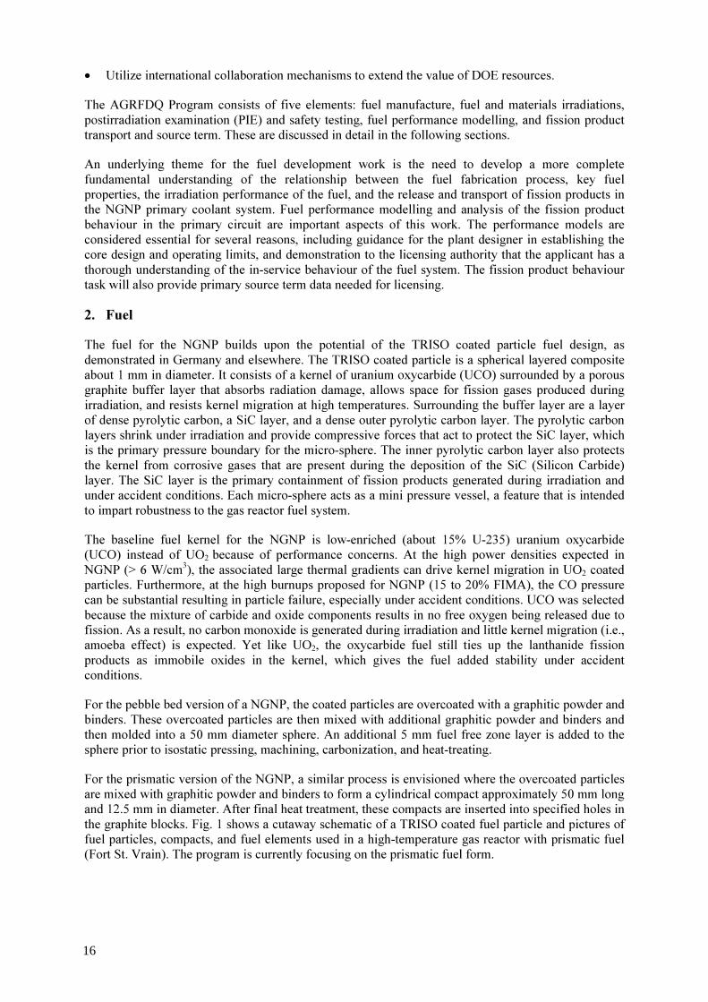
• Utilize international collaboration mechanisms to extend the value of DOE resources. The AGRFDQ Program consists of five elements: fuel manufacture, fuel and materials irradiations, postirradiation examination (PIE) and safety testing, fuel performance modelling, and fission product transport and source term. These are discussed in detail in the following sections. An underlying theme for the fuel development work is the need to develop a more complete fundamental understanding of the relationship between the fuel fabrication process, key fuel properties, the irradiation performance of the fuel, and the release and transport of fission products in the NGNP primary coolant system. Fuel performance modelling and analysis of the fission product behaviour in the primary circuit are important aspects of this work. The performance models are considered essential for several reasons, including guidance for the plant designer in establishing the core design and operating limits, and demonstration to the licensing authority that the applicant has a thorough understanding of the in-service behaviour of the fuel system. The fission product behaviour task will also provide primary source term data needed for licensing. 2. Fuel The fuel for the NGNP builds upon the potential of the TRISO coated particle fuel design, as demonstrated in Germany and elsewhere. The TRISO coated particle is a spherical layered composite about 1 mm in diameter. It consists of a kernel of uranium oxycarbide (UCO) surrounded by a porous graphite buffer layer that absorbs radiation damage, allows space for fission gases produced during irradiation, and resists kernel migration at high temperatures. Surrounding the buffer layer are a layer of dense pyrolytic carbon, a SiC layer, and a dense outer pyrolytic carbon layer. The pyrolytic carbon layers shrink under irradiation and provide compressive forces that act to protect the SiC layer, which is the primary pressure boundary for the micro-sphere. The inner pyrolytic carbon layer also protects the kernel from corrosive gases that are present during the deposition of the SiC (Silicon Carbide) layer. The SiC layer is the primary containment of fission products generated during irradiation and under accident conditions. Each micro-sphere acts as a mini pressure vessel, a feature that is intended to impart robustness to the gas reactor fuel system. The baseline fuel kernel for the NGNP is low-enriched (about 15% U-235) uranium oxycarbide (UCO) instead of UO2 because of performance concerns. At the high power densities expected in NGNP (> 6 W/cm3), the associated large thermal gradients can drive kernel migration in UO2 coated particles. Furthermore, at the high burnups proposed for NGNP (15 to 20% FIMA), the CO pressure can be substantial resulting in particle failure, especially under accident conditions. UCO was selected because the mixture of carbide and oxide components results in no free oxygen being released due to fission. As a result, no carbon monoxide is generated during irradiation and little kernel migration (i.e., amoeba effect) is expected. Yet like UO2, the oxycarbide fuel still ties up the lanthanide fission products as immobile oxides in the kernel, which gives the fuel added stability under accident conditions. For the pebble bed version of a NGNP, the coated particles are overcoated with a graphitic powder and binders. These overcoated particles are then mixed with additional graphitic powder and binders and then molded into a 50 mm diameter sphere. An additional 5 mm fuel free zone layer is added to the sphere prior to isostatic pressing, machining, carbonization, and heat-treating. For the prismatic version of the NGNP, a similar process is envisioned where the overcoated particles are mixed with graphitic powder and binders to form a cylindrical compact approximately 50 mm long and 12.5 mm in diameter. After final heat treatment, these compacts are inserted into specified holes in the graphite blocks. Fig. 1 shows a cutaway schematic of a TRISO coated fuel particle and pictures of fuel particles, compacts, and fuel elements used in a high-temperature gas reactor with prismatic fuel (Fort St. Vrain). The program is currently focusing on the prismatic fuel form.
16

FIG. 1. Cutaway schematic of a TRISO coated fuel particle and pictures of prismatic fuelled high-temperature gas reactor fuel particles, compacts, and fuel elements. 3. Historical review: The starting point A recent review [1] has concluded that there has historically been a difference in the quality of US and German fuel. This difference has been traced to technical differences in the fabrication processes used in Germany and the US as well as different philosophies used to implement the irradiation and testing programs in the two countries. A review of the fabrication processes used in Germany and the US to make coated particle fuel indicates that the scale of fuel fabrication and development efforts in the last 25 years were quite different. German fabrication was at an industrial/production scale supporting the German Arbeitsgemeinschaft Versuchreaktor (AVR) and thorium high temerature reactor (THTR). Only about 100 defects were measured in 3.3 million particles produced. The post Fort St. Vrain US program was a mixture of lab scale and larger scale fabrication. The initial defect levels varied greatly and were much greater than those produced in Germany. A comparison of the fabrication processes has revealed many differences in the overall process. There are three specific technical differences in the coating layers produced by the respective fabrication processes that have important impacts in terms of performance under irradiation and accident conditions: pyrocarbon (PyC) anisotropy and density, IPyC/SiC (inner pyro-carbon/ silicon carbide) interface structure, and SiC microstructure. 3.1. Pyrocarbon coating rate The density and anisotropy of PyC is determined by the conditions in the coater [2]. German PyC is deposited at a higher coating gas concentration, which in turn results in a higher coating rate (~ 4-6 mm/minute). This PyC is very isotropic and thus survives irradiation quite well. However, the conditions appear to lead to somewhat greater surface porosity than in U.S. PyC. U.S. PyC has been coated under a variety of conditions. In many cases, it was coated at very low coating gas concentrations, which results in a lower coating rate (1-4 mm/minute), and leads not only to a very dense and impermeable IPyC layer, which is important to preventing attack of the kernel by the
UCO KernelPorous Carbon BufferSilicon CarbidePyrolytic Carbon
PARTICLES COMPACTS FUEL ELEMENTS
TRISO Coated fuel particles (left) are formed into fuelrods (center) and inserted into graphite fuel elements(right).
17
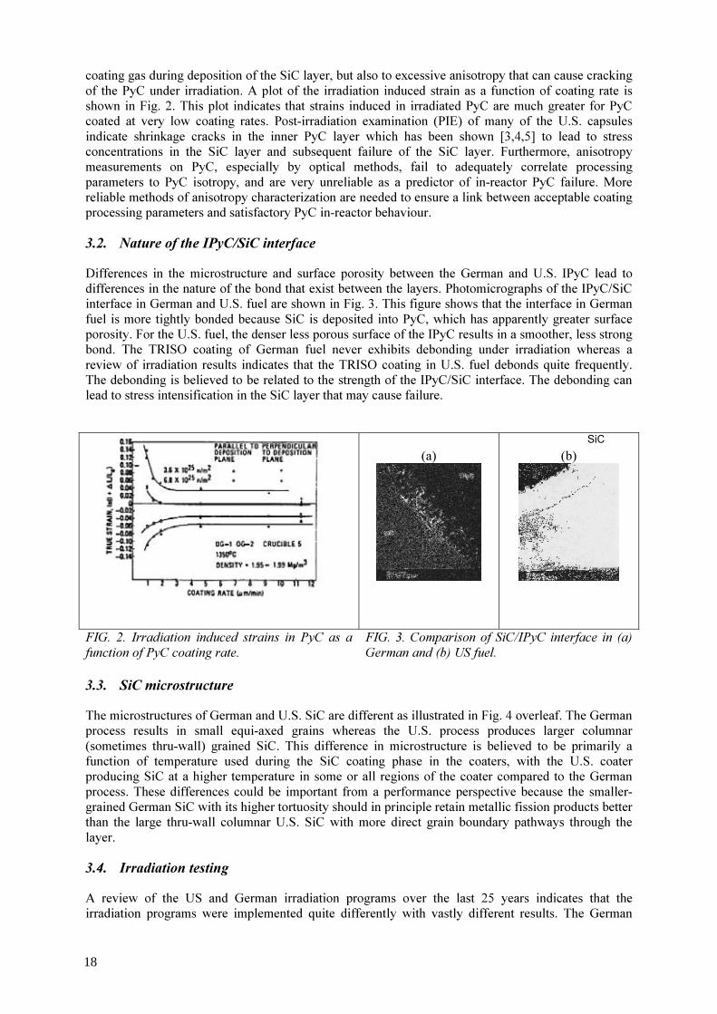
coating gas during deposition of the SiC layer, but also to excessive anisotropy that can cause cracking of the PyC under irradiation. A plot of the irradiation induced strain as a function of coating rate is shown in Fig. 2. This plot indicates that strains induced in irradiated PyC are much greater for PyC coated at very low coating rates. Post-irradiation examination (PIE) of many of the U.S. capsules indicate shrinkage cracks in the inner PyC layer which has been shown [3,4,5] to lead to stress concentrations in the SiC layer and subsequent failure of the SiC layer. Furthermore, anisotropy measurements on PyC, especially by optical methods, fail to adequately correlate processing parameters to PyC isotropy, and are very unreliable as a predictor of in-reactor PyC failure. More reliable methods of anisotropy characterization are needed to ensure a link between acceptable coating processing parameters and satisfactory PyC in-reactor behaviour. 3.2. Nature of the IPyC/SiC interface Differences in the microstructure and surface porosity between the German and U.S. IPyC lead to differences in the nature of the bond that exist between the layers. Photomicrographs of the IPyC/SiC interface in German and U.S. fuel are shown in Fig. 3. This figure shows that the interface in German fuel is more tightly bonded because SiC is deposited into PyC, which has apparently greater surface porosity. For the U.S. fuel, the denser less porous surface of the IPyC results in a smoother, less strong bond. The TRISO coating of German fuel never exhibits debonding under irradiation whereas a review of irradiation results indicates that the TRISO coating in U.S. fuel debonds quite frequently. The debonding is believed to be related to the strength of the IPyC/SiC interface. The debonding can lead to stress intensification in the SiC layer that may cause failure.
(a)
(b)
FIG. 2. Irradiation induced strains in PyC as a function of PyC coating rate.
FIG. 3. Comparison of SiC/IPyC interface in (a) German and (b) US fuel.
3.3. SiC microstructure The microstructures of German and U.S. SiC are different as illustrated in Fig. 4 overleaf. The German process results in small equi-axed grains whereas the U.S. process produces larger columnar (sometimes thru-wall) grained SiC. This difference in microstructure is believed to be primarily a function of temperature used during the SiC coating phase in the coaters, with the U.S. coater producing SiC at a higher temperature in some or all regions of the coater compared to the German process. These differences could be important from a performance perspective because the smaller-grained German SiC with its higher tortuosity should in principle retain metallic fission products better than the large thru-wall columnar U.S. SiC with more direct grain boundary pathways through the layer. 3.4. Irradiation testing A review of the US and German irradiation programs over the last 25 years indicates that the irradiation programs were implemented quite differently with vastly different results. The German
SiC
18
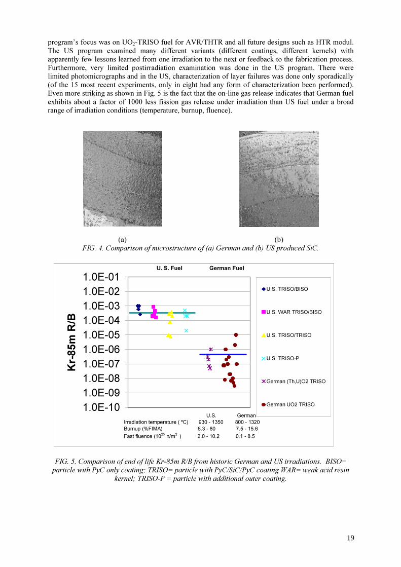
program’s focus was on UO2-TRISO fuel for AVR/THTR and all future designs such as HTR modul. The US program examined many different variants (different coatings, different kernels) with apparently few lessons learned from one irradiation to the next or feedback to the fabrication process. Furthermore, very limited postirradiation examination was done in the US program. There were limited photomicrographs and in the US, characterization of layer failures was done only sporadically (of the 15 most recent experiments, only in eight had any form of characterization been performed). Even more striking as shown in Fig. 5 is the fact that the on-line gas release indicates that German fuel exhibits about a factor of 1000 less fission gas release under irradiation than US fuel under a broad range of irradiation conditions (temperature, burnup, fluence).
(a) (b)
FIG. 4. Comparison of microstructure of (a) German and (b) US produced SiC.
FIG. 5. Comparison of end of life Kr-85m R/B from historic German and US irradiations. BISO=
particle with PyC only coating; TRISO= particle with PyC/SiC/PyC coating WAR= weak acid resin kernel; TRISO-P = particle with additional outer coating.
1.0E-101.0E-091.0E-081.0E-071.0E-061.0E-051.0E-041.0E-031.0E-021.0E-01
Kr-8
5m R
/B
U.S. TRISO/BISO
U.S. WAR TRISO/BISO
U.S. TRISO/TRISO
U.S. TRISO-P
German (Th,U)O2 TRISO
German UO2 TRISO
U. S. Fuel German Fuel
U.S. GermanIrradiation temperature ( ºC) 930 - 1350 800 - 1320Burnup (%FIMA) 6.3 - 80 7.5 - 15.6Fast fluence (1025 n/m2 ) 2.0 - 10.2 0.1 - 8.5
19

Furthermore, the postirradiation examination confirms the more extensive gas release data. German fuel is excellent. Out of ~ 340 000 particles tested there were no in-pile failures and a few “damaged” particles due to experimental anomalies. Gas release was attributed only to as-manufactured defects and heavy metal contamination. US fuel did not perform very well. Percent level failures of fuel and in many cases very high levels of failures of individual layers of the TRISO coated were observed following irradiation in most experiments (see Fig. 6). A variety of failure mechanisms were noted related to effects of accelerated irradiation and attributes of the fabrication process. This comparison strongly supports the need for process improvement studies for fuel manufactured using the traditional US methods and potential scoping irradiations to demonstrate the effectiveness of any changes in the process.
0.1
1
10
100 IPyC LayerSiC LayerOPyC Layer
FIG. 6. Failures observed during postirradiation examination of US coated particle fuel over the past 25 years. 4. Fuel manufacture This program element addresses the work necessary to produce coated-particle fuel that meets fuel performance specifications and includes process development for kernels, coatings, and compacting; quality control (QC) methods development; scale-up analyses; and process documentation needed for technology transfer. This effort will produce fuel and material samples for characterization, irradiation, and accident testing as necessary to meet the overall goals. There will also eventually be work to develop automated fuel fabrication technology suitable for mass production of coated-particle fuel at an acceptable cost; that work will be conducted during the later stages of the program in conjunction with co-sponsoring industrial partners. Near term activities are focused on production of UCO kernels and coating of particles in a continuous process using a small (two inch) lab scale coater. The goal of these initial coating studies are to provide coatings produced under a range of coating conditions. The goal is to produce coatings like those produced by the German program in the late 1980s. However, coating variants are planned that will confirm the understanding of the historical coating fabrication database and some will then be irradiated in the first irradiation test, AGR-1. The coating rates and temperatures for the coating variants that are planned for the AGR-1 fuel fabrication campaign are listed in Table 1. Coating conditions that span the range from producing highly anisotropic/high density PyC to highly isotropic/low density PyC are planned. Two different SiC coating temperatures (1510 and 1580 °C)
20

are planned to determine an acceptable window for producing the desired fine-grained SiC. An interrupted run is also planned to more quantitatively characterize fuel produced in both interrupted and uninterrupted modes. Additionally, a variant in which Argon gas is used during SiC coating is planned since the UK Dragon project and current microelectronics production has demonstrated that good SiC can be produced at much lower temperatures when this gas is used. TABLE 1. COATING VARIANTS FOR AGR-1
Coating Variant
IPyC Conditions SiC Conditions Comment 1 1300 ºC,
4.5 mm/min 1510 ºC 0.2-0.25 mm//min
German Baseline 2 1300 ºC,
4.5 mm/min 1580 ºC 0.2-0.25 mm//min
Higher SiC deposition temp 3 1300 ºC,
2.0 mm/min 1510 ºC 0.2-0.25 mm//min
Low IPyC coating rate - anisotropic
4 1300 ºC, 2.0 mm/min
1580 ºC 0.2-0.25 mm//min
Low IPyC coating rate - anisotropic
5 1300 ºC, 6 mm/min
1510 ºC 0.2-0.25 mm//min
High IPyC coating rate 6 1300 ºC,
6 mm/min 1580 ºC 0.2-0.25 mm//min
Higher SiC deposition temp 7 1300 ºC,
4.5 mm/min 1510 ºC 0.2-0.25 mm//min
Interrupted variant of case 1 8 1300 ºC,
4.5 mm/min ~ 1300 ºC with Argon
The coated particles will then be molded into cylindrical compacts consisting of carbon based thermosetting resin. This compact matrix material is the same as used in the German program. The second phase of coating development involves scale up of the continuous coating process to production size (e.g. six inch coater) coaters. The goal is to produce high quality coatings for performance demonstration and ultimate qualification. In parallel with the fuel fabrication, additional effort is being expended in the area of fuel characterization with the goal of providing more advanced and more robust techniques to measure key attributes of the fuel that can be integrated into a continuous production scale coating process. Initial activities are focused on developing improved anisotropy, and sphericity measurement techniques. Advanced tomography techniques to measure layer thicknesses and densities are also under consideration. 5. Fuel and materials irradiation The fuel and materials irradiation activities will provide data on fuel performance under irradiation as necessary to support fuel process development, to qualify fuel for normal operation conditions, and to support development and validation of fuel performance and fission product transport models and codes. The irradiations will also provide irradiated fuel and materials as necessary for post irradiation examination (PIE) and ex-core high-temperature furnace safety testing. A total of eight irradiation capsules will be used to provide the necessary data and sample materials. Details on each irradiation are listed in the Table 2. AGR-1 is a shakedown capsule. The purpose is to test a number of variants of fuel produced under different processing conditions from laboratory scale coating equipment. AGR-2 will be a performance demonstration irradiation with fuel fabricated from a production scale coater. Feedback to the fabrication process is expected following both AGR-1 and AGR-2. AGR-3 is devoted to obtaining data on fission gases and fission metals under normal
21

irradiation conditions. In AGR-4, fission product behaviour in fuel compact matrix and graphite materials will be studied. Given the statistical nature of coated particle fuel, a large number of fuel specimens are needed to fully qualify the fuel and demonstrate compliance with the fuel failure specification. AGR-5 and AGR-6 are identical irradiations that will be used to qualify the fuel for the NGNP. AGR-7 and AGR-8 are irradiations designed to provide data with which to verify and validate fuel performance and fission product transport models. TABLE 2. PLANNED AGR IRRADIATION CAPSULES
Capsule Task AGR-1 Shakedown and early fuel AGR-2 Performance test fuel AGR-3 Fission product transport - 1 AGR-4 Fission product transport - 2 AGR-5 Fuel qualification - 1 AGR-6 Fuel qualification - 2 AGR-7 Fuel performance model validation AGR-8 Fission product transport -3
Each capsule will be a highly instrumented multi-cell capsule capable of irradiating six different fuel forms to different thermal conditions if required. Flux wires will be used to measure the thermal and fast neutron fluences. Thermocouples in graphite bodies surrounding the fuel will be used to monitor temperatures during the irradiation. The graphite bodies may contain boron carbide to control power generation during the irradiation and prevent large power swings historically experienced when irradiating fuel to high burnup. During the irradiation, a low flow of inert sweep gas is used to provide the correct thermal conductance to allow the fuel to be irradiated at the proper temperature. Usually this sweep/ thermal control gas is helium. Small amounts of neon are used to change the overall conductance to compensate for depletion of uranium due to burnup and still keep the fuel at the required temperature. A schematic of a test train used for AGR-1 is shown in Fig. 7.
FIG. 7. Schematic of AGR-1 multi-cell capsule.
22
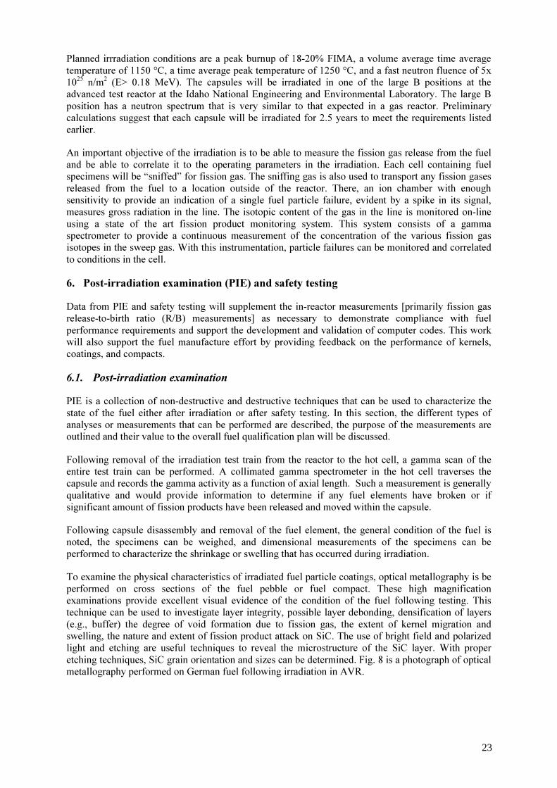
Planned irrradiation conditions are a peak burnup of 18-20% FIMA, a volume average time average temperature of 1150 °C, a time average peak temperature of 1250 °C, and a fast neutron fluence of 5x 1025 n/m2 (E> 0.18 MeV). The capsules will be irradiated in one of the large B positions at the advanced test reactor at the Idaho National Engineering and Environmental Laboratory. The large B position has a neutron spectrum that is very similar to that expected in a gas reactor. Preliminary calculations suggest that each capsule will be irradiated for 2.5 years to meet the requirements listed earlier. An important objective of the irradiation is to be able to measure the fission gas release from the fuel and be able to correlate it to the operating parameters in the irradiation. Each cell containing fuel specimens will be “sniffed” for fission gas. The sniffing gas is also used to transport any fission gases released from the fuel to a location outside of the reactor. There, an ion chamber with enough sensitivity to provide an indication of a single fuel particle failure, evident by a spike in its signal, measures gross radiation in the line. The isotopic content of the gas in the line is monitored on-line using a state of the art fission product monitoring system. This system consists of a gamma spectrometer to provide a continuous measurement of the concentration of the various fission gas isotopes in the sweep gas. With this instrumentation, particle failures can be monitored and correlated to conditions in the cell. 6. Post-irradiation examination (PIE) and safety testing Data from PIE and safety testing will supplement the in-reactor measurements [primarily fission gas release-to-birth ratio (R/B) measurements] as necessary to demonstrate compliance with fuel performance requirements and support the development and validation of computer codes. This work will also support the fuel manufacture effort by providing feedback on the performance of kernels, coatings, and compacts. 6.1. Post-irradiation examination PIE is a collection of non-destructive and destructive techniques that can be used to characterize the state of the fuel either after irradiation or after safety testing. In this section, the different types of analyses or measurements that can be performed are described, the purpose of the measurements are outlined and their value to the overall fuel qualification plan will be discussed. Following removal of the irradiation test train from the reactor to the hot cell, a gamma scan of the entire test train can be performed. A collimated gamma spectrometer in the hot cell traverses the capsule and records the gamma activity as a function of axial length. Such a measurement is generally qualitative and would provide information to determine if any fuel elements have broken or if significant amount of fission products have been released and moved within the capsule. Following capsule disassembly and removal of the fuel element, the general condition of the fuel is noted, the specimens can be weighed, and dimensional measurements of the specimens can be performed to characterize the shrinkage or swelling that has occurred during irradiation. To examine the physical characteristics of irradiated fuel particle coatings, optical metallography is be performed on cross sections of the fuel pebble or fuel compact. These high magnification examinations provide excellent visual evidence of the condition of the fuel following testing. This technique can be used to investigate layer integrity, possible layer debonding, densification of layers (e.g., buffer) the degree of void formation due to fission gas, the extent of kernel migration and swelling, the nature and extent of fission product attack on SiC. The use of bright field and polarized light and etching are useful techniques to reveal the microstructure of the SiC layer. With proper etching techniques, SiC grain orientation and sizes can be determined. Fig. 8 is a photograph of optical metallography performed on German fuel following irradiation in AVR.
23
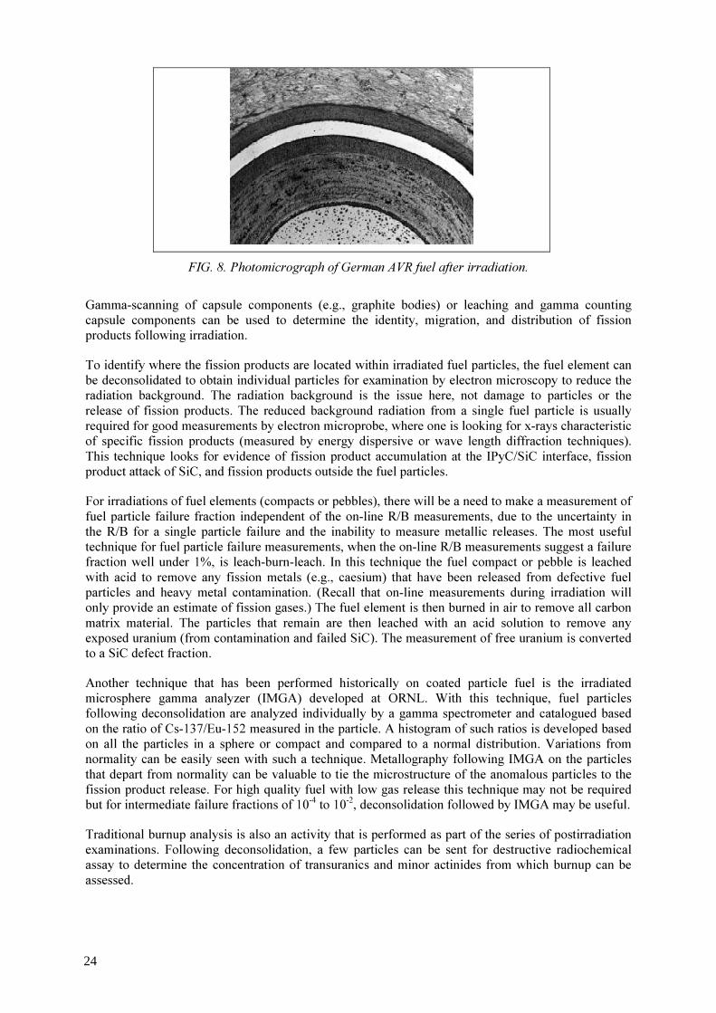
FIG. 8. Photomicrograph of German AVR fuel after irradiation.
Gamma-scanning of capsule components (e.g., graphite bodies) or leaching and gamma counting capsule components can be used to determine the identity, migration, and distribution of fission products following irradiation. To identify where the fission products are located within irradiated fuel particles, the fuel element can be deconsolidated to obtain individual particles for examination by electron microscopy to reduce the radiation background. The radiation background is the issue here, not damage to particles or the release of fission products. The reduced background radiation from a single fuel particle is usually required for good measurements by electron microprobe, where one is looking for x-rays characteristic of specific fission products (measured by energy dispersive or wave length diffraction techniques). This technique looks for evidence of fission product accumulation at the IPyC/SiC interface, fission product attack of SiC, and fission products outside the fuel particles. For irradiations of fuel elements (compacts or pebbles), there will be a need to make a measurement of fuel particle failure fraction independent of the on-line R/B measurements, due to the uncertainty in the R/B for a single particle failure and the inability to measure metallic releases. The most useful technique for fuel particle failure measurements, when the on-line R/B measurements suggest a failure fraction well under 1%, is leach-burn-leach. In this technique the fuel compact or pebble is leached with acid to remove any fission metals (e.g., caesium) that have been released from defective fuel particles and heavy metal contamination. (Recall that on-line measurements during irradiation will only provide an estimate of fission gases.) The fuel element is then burned in air to remove all carbon matrix material. The particles that remain are then leached with an acid solution to remove any exposed uranium (from contamination and failed SiC). The measurement of free uranium is converted to a SiC defect fraction. Another technique that has been performed historically on coated particle fuel is the irradiated microsphere gamma analyzer (IMGA) developed at ORNL. With this technique, fuel particles following deconsolidation are analyzed individually by a gamma spectrometer and catalogued based on the ratio of Cs-137/Eu-152 measured in the particle. A histogram of such ratios is developed based on all the particles in a sphere or compact and compared to a normal distribution. Variations from normality can be easily seen with such a technique. Metallography following IMGA on the particles that depart from normality can be valuable to tie the microstructure of the anomalous particles to the fission product release. For high quality fuel with low gas release this technique may not be required but for intermediate failure fractions of 10-4 to 10-2, deconsolidation followed by IMGA may be useful. Traditional burnup analysis is also an activity that is performed as part of the series of postirradiation examinations. Following deconsolidation, a few particles can be sent for destructive radiochemical assay to determine the concentration of transuranics and minor actinides from which burnup can be assessed.
24
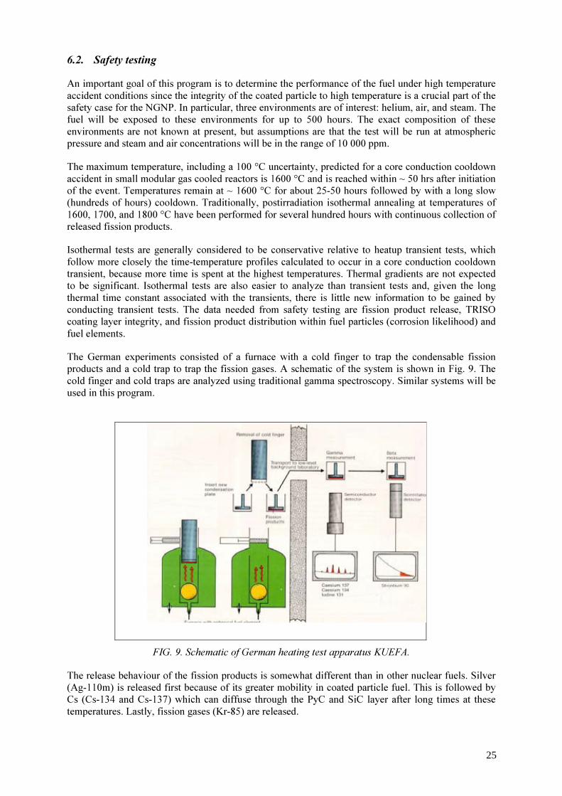
6.2. Safety testing An important goal of this program is to determine the performance of the fuel under high temperature accident conditions since the integrity of the coated particle to high temperature is a crucial part of the safety case for the NGNP. In particular, three environments are of interest: helium, air, and steam. The fuel will be exposed to these environments for up to 500 hours. The exact composition of these environments are not known at present, but assumptions are that the test will be run at atmospheric pressure and steam and air concentrations will be in the range of 10 000 ppm. The maximum temperature, including a 100 °C uncertainty, predicted for a core conduction cooldown accident in small modular gas cooled reactors is 1600 °C and is reached within ~ 50 hrs after initiation of the event. Temperatures remain at ~ 1600 °C for about 25-50 hours followed by with a long slow (hundreds of hours) cooldown. Traditionally, postirradiation isothermal annealing at temperatures of 1600, 1700, and 1800 °C have been performed for several hundred hours with continuous collection of released fission products. Isothermal tests are generally considered to be conservative relative to heatup transient tests, which follow more closely the time-temperature profiles calculated to occur in a core conduction cooldown transient, because more time is spent at the highest temperatures. Thermal gradients are not expected to be significant. Isothermal tests are also easier to analyze than transient tests and, given the long thermal time constant associated with the transients, there is little new information to be gained by conducting transient tests. The data needed from safety testing are fission product release, TRISO coating layer integrity, and fission product distribution within fuel particles (corrosion likelihood) and fuel elements. The German experiments consisted of a furnace with a cold finger to trap the condensable fission products and a cold trap to trap the fission gases. A schematic of the system is shown in Fig. 9. The cold finger and cold traps are analyzed using traditional gamma spectroscopy. Similar systems will be used in this program.
FIG. 9. Schematic of German heating test apparatus KUEFA.
The release behaviour of the fission products is somewhat different than in other nuclear fuels. Silver (Ag-110m) is released first because of its greater mobility in coated particle fuel. This is followed by Cs (Cs-134 and Cs-137) which can diffuse through the PyC and SiC layer after long times at these temperatures. Lastly, fission gases (Kr-85) are released.
25

Post heating test activities include the characterization of TRISO coating layer integrity by optical metallography, looking for evidence of SiC layer thinning and decomposition, chemical attack of SiC, and mechanical condition and microstructures of the SiC and PyC layers. Detailed test matrices will be developed as the program evolves. 7. Fuel performance and modelling Computer codes and models will be further developed and validated as necessary to support fuel fabrication process development and plant design and licensing. The fuel performance modelling will address the structural, thermal, and chemical processes that can lead to coated-particle failures. The models will address the release of fission products from the fuel particle and the effects of fission product chemical interactions with the coatings, which can lead to degradation of the coated-particle properties. Compared to light water reactor and liquid metal reactor fuel forms, the behaviour of coated-particle fuel is inherently more multidimensional. Moreover, modelling of fuel behaviour is made more difficult because of statistical variations in fuel physical dimensions and/or component properties, from particle to particle due to the nature of the chemical vapour deposition fabrication process. Previous attempts to model this fuel form have attacked different pieces of the problem. Simplified one-dimensional models exist to describe the structural response of the fuel particle. Models or correlations exist to describe the fission product behaviour in the fuel, though the database may not be complete owing to the changes in fuel design that have occurred over the last 25 years. Significant effort has gone into modelling the statistical nature of fuel particles. However, under pressure to perform over one million simulations with the computing power available in the 1970s and 1980s, the structural response of the particle was simplified to improve the speed of calculation. New models are currently being developed in the US that represent a first-principles-based mechanistic, integrated, thermal-mechanical-physio-chemical-irradiation performance model for particle fuel, which has the proper dimensionality, yet captures the statistical nature and loading of the fuel. The mechanistic model for coated-particle fuel considers both the structural and physio-chemical behaviour of particle-coated fuel system during irradiation. The following important phenomena are included: • Anisotropic response of the pyrolytic carbon layers to irradiation (shrinkage, swelling, and creep
that are functions of temperature, fluence, and orientation/direction in the carbon); • Failure of a SiC ceramic in the coating system (using the classic Weibull formulation for a brittle
material), either by traditional pressure vessel failure criteria or by mechanisms such as asphericity, layer debonding, or cracking;
• Chemical changes of the fuel kernel during irradiation (changes in carbon/oxygen, carbon/metal and/or oxygen/metal ratio depending on the kernel fuel type, production of CO/CO2 gas) and its influence on fission product and/or kernel attack on the particle coatings;
• Thermo-mechanical response of the kernel and buffer as a result of buffer densification, kernel swelling, and gas generation (fission gases and CO), including the development of gaps between the buffer and the TRISO-coating layers as a function of burnup, fast fluence and temperature;
• Attack of the SiC layer by Pd and other fission products, and by kernel migration; • Transport of key fission products (Kr, Ag, Sr, Cs) from the kernel and through each layer of the
particle; and • Statistical variations of key properties of the particle associated with the production process,
requiring Monte Carlo analysis of a very large number of particles to understand the aggregate behaviour. Fabricated particles will exhibit statistical distributions for not only the physical dimensions of the individual coatings, but also for the mechanical properties of these layers.
26
These models have had some success in developing an understanding of fuel failure mechanisms in US fuel over the last decade. Such a tool can be very useful as both pretest and posttest predictions for any experiment performed in this program. In addition, sensitivity studies with the model can be used to identify critical materials properties data and constitutive relations whose uncertainty needs to be reduced because they drive the predicted performance of the coated fuel particle. Furthermore, the use of piggyback cells in the irradiation capsules can be used to study those key individual phenomena in coated particles that have high uncertainty (e.g., shrinkage and swelling of PyC, fission product release behaviour in a purposely defective or initially failed particle). Moreover, some of the PIE techniques can provide maps of fission products through the particle, which can be compared with model predictions on fission product transport through the coatings. All of this type of data will eventually be needed to validate the overall performance model. Such fuel performance models will eventually be needed to provide some understanding of fuel behaviour inside the operations and safety envelope defined by the irradiation and safety testing (i.e. interpolation) and outside these envelopes where the margins of failure of the fuel may be approached (i.e., extrapolation). Finally, a validated fuel performance model can be used to help evaluate and guide potential future changes in the next generation coated particle fuel. The importance of fuel performance modelling has been recognized internationally. The US is part of an IAEA coordinated research project on coated particle fuel technology. A key task is associated with benchmarking coated particle fuel performance models under both normal and off-normal conditions. The fuel behaviour models under development by the AGR program are part of the international benchmark. 8. Fission product transport and source term The transport of fission products produced within the coated particles will be modelled to provide a technical basis for source terms for advanced gas reactors under normal and accident conditions. The design methods (computer models) will be validated by experimental data, as necessary to support plant design and licensing. The NRC will require validated computer models that predict accurately the following phenomena: • Fission product release from the kernel; • Transport through failed coatings; • Deposition fraction of the released fission products in the compact or sphere matrix; • Deposition fraction of what gets through the compact on fuel element graphite (prismatic variant
only); • Deposition fraction of what gets out of the fuel element to metallic surfaces in the primary circuit; • Re-entrainment of deposited fission products during an elevated temperature accident, or
depressurization event; and • Transport of fission products on dust particles, and subsequent release to the environment if the
primary circuit is breached. Each of the phenomena listed above is complex, and difficult to model. It is also difficult to design and conduct experiments that can cover the multitude of variables that affect the physical situation. The AGR program has developed a research and development plan that, when the work is successfully completed, will produce a technical basis for source terms under normal and accident conditions for advanced gas-cooled reactors. The program consists of irradiations to provide data on fission gas and fission metal release from the kernel and transport through failed coatings (AGR-3), fission product transport behaviour in the fuel element matrix and graphite block (AGR-4), out of pile experiments to characterize plateout and reentrainment of fission products during accident conditions. The program also contains an irradiation (AGR-8) that will be used to validate the computer models that describe the in-vessel gas reactor source term.
27

9. Summary and conclusions The DOE AGR Fuel Development and Qualification consists of five elements: fuel manufacture, fuel and materials irradiations, safety testing and PIE, fuel performance modelling, and fission product transport and source term. The goal is to qualify the fuel form for use in the NGNP (burnup of 18-20% FIMA, a volume average time average temperature of 1150 °C, a time average peak temperature of 1250 °C, and a fast neutron fluence of 5 x 1025 n/m2 (E> 0.18 MeV), high fission product retentiveness for hundreds of hours at 1600 °C). The fuel form is based on reference UCO, SiC TRISO particles in thermosetting resin, incorporating past German fabrication experience. An underlying theme for the fuel development work is the need to develop a more complete fundamental understanding of the relationship between the fuel fabrication process, key fuel properties, the irradiation performance of the fuel, and the release and transport of fission products in the NGNP primary coolant system. The logic of the program is structured such that there are multiple feedback loops and opportunities for improvement in the fabrication process based upon early results. Fuel performance modelling and analysis of the fission product behaviour in the primary circuit are important aspects of this work. The performance models are considered essential for several reasons, including guidance for the plant designer in establishing the core design and operating limits, and demonstration to the licensing authority that the applicant has a thorough understanding of the in-service behaviour of the fuel system. The fission product behaviour task will also provide primary source term data needed for licensing.
REFERENCES [1] PETTI, D.A., BUONGIORNO, J., MAKI, J.T., HOBBINS, R. R., and MILLER, G.K.,
“Key Differences in the Fabrication, Irradiation and High Temperature Accident Testing of U.S. and German TRISO-coated Particle Fuel and Their Implications on Fuel Performance,” Nuclear Engineering and Design, 222 (2003) pp. 281-297.
[2] INTERNATIONAL ATOMIC ENERGY AGENCY, “Irradiation Damage in Graphite due to Fast Neutrons in Fission and Fusion Systems, IAEA-TECDOC-1154, (2000).
[3] BALDWIN, C.A., et al., “The New Production Reactor Post Irradiation Examination Data Report for Capsules NPR-1, NPR-2 and NPR-1A,” ORNL/M-2849, ORNL, TN, (1993).
[4] MAKI, J.T., et al., “NP-MHTGR Fuel Development Program Results,” INEEL/EXT-2002-1268, Idaho National Engineering and Environmental Laboratory,Bechtel BWXT Idaho, LLC (2002). http://www.inl.gov/technicalpublications/Documents/2699518.pdf
[5] MILLER, G.K., PETTI, D.A., VARACALLE, D.J., MAKI, J.T., “Consideration of the Effects on Fuel Particle Behaviour from Shrinkage Cracks in the Inner Pyrocarbon Layer,” J. Nucl. Materials, Vol. 295,(2001) pp. 205-212.
28

The current state of the HTGR core component fabrication technologies in the Ukraine and some properties of materials and products
M.P. Odeychuk, V.F. Zelenskiy, V.A. Gurin, V.K. Yakovlev National Science Centre KIPT-“Kharkov Institute of Physics & Technology” Kharkov, Ukraine
Abstract. A review of the status of work on spherical pyrocarbon (PyC)-bounded fuel elements on the basis of uranium dioxide, uranium carbonitride and thorium dioxide for high-temperature gas-cooled reactors HTGR is given. The process flow diagram for production of fuel microspheres, coated particles and spherical fuel elements are described. In the paper are considered some special features of fabricating carbon-graphite materials and products using the methods of volume gas-phase impregnation of porous materials withPyC. Results of tests of the characteristics of spherical fuel elements and their components, the materials and products with a PyC binder, including irradiation conditions, are discussed.
1. Introduction High-temperature gas-cooled reactors (HTGR) are a new development in atomic power engineering. They differ from other types of reactors making an opportunity for combined production of electric and thermal power for industrial and public utility uses. So, it is possible to reduce substantially the part of oil and gases, being in very short supply, in the thermal energy production. Besides, these reactors possess a high safety, economic fuel cycle, high thermal efficiency (40%) and so on. For HTGRs developed in the former USSR, the concept of spherical fuel element (SFE), such as those applied in the AVR and THTR-300 reactors (Germany), was accepted. Planned were multiple passes of fuel elements and absorber elements through the reactor core, and for the VGR-50 plant also through the channels of the external gamma-irradiation source, intended for conducting radiation-chemical processes. Thus, the requirements to the strength characteristics, in particular the wear resistance, are very stiffened. A special feature of HTGR unlike other reactor modes is the wide graphite application in the reactor core. Therein it acts both as a neutron moderator and a reflector. In fabricating carbon-graphite components of the HTGR core, the industrial fabrication methods for the graphite materials are principally used, which did not change much since the half of the last century. They are based on pressing or extrusion of coke powder with a binder and a subsequent carbonizing and graphitizing annealing of the produced blocks [1]. Though in the last years, new trends in the carbon technology were developed (pressing on the carbonizing annealing stage, thermal treatment and machining on the graphitizing stage, application of row and semi-annealed cokes, isostatic compaction, high-temperature catalysis, etc.), only few from them were suitable for solving the problems of large-sized blocks of reactor graphite [2]. In the last few decades, in the carbon-graphite material technology there have appeared at least two radically new trends, which make it possible to improve essentially their operating characteristics. Here we mean gas-phase (CVD= chemical vapour deposition) methods and the development of carbon fiber (CF) and carbon-carbon composites (CCC) with these CF as a base. Both trends have been actively developed just for the solution of HTGR problems [3,4]. However, they have not found wide
29
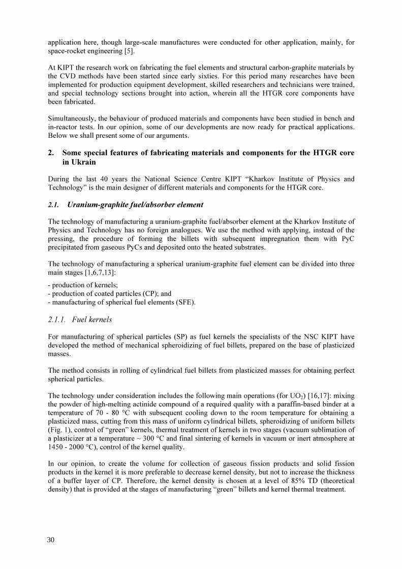
application here, though large-scale manufactures were conducted for other application, mainly, for space-rocket engineering [5]. At KIPT the research work on fabricating the fuel elements and structural carbon-graphite materials by the CVD methods have been started since early sixties. For this period many researches have been implemented for production equipment development, skilled researchers and technicians were trained, and special technology sections brought into action, wherein all the HTGR core components have been fabricated. Simultaneously, the behaviour of produced materials and components have been studied in bench and in-reactor tests. In our opinion, some of our developments are now ready for practical applications. Below we shall present some of our arguments. 2. Some special features of fabricating materials and components for the HTGR core
in Ukrain During the last 40 years the National Science Centre KIPT “Kharkov Institute of Physics and Technology” is the main designer of different materials and components for the HTGR core. 2.1. Uranium-graphite fuel/absorber element The technology of manufacturing a uranium-graphite fuel/absorber element at the Kharkov Institute of Physics and Technology has no foreign analogues. We use the method with applying, instead of the pressing, the procedure of forming the billets with subsequent impregnation them with PyC precipitated from gaseous PyCs and deposited onto the heated substrates. The technology of manufacturing a spherical uranium-graphite fuel element can be divided into three main stages [1,6,7,13]: - production of kernels; - production of coated particles (CP); and - manufacturing of spherical fuel elements (SFE).
2.1.1. Fuel kernels For manufacturing of spherical particles (SP) as fuel kernels the specialists of the NSC KIPT have developed the method of mechanical spheroidizing of fuel billets, prepared on the base of plasticized masses. The method consists in rolling of cylindrical fuel billets from plasticized masses for obtaining perfect spherical particles. The technology under consideration includes the following main operations (for UO2) [16,17]: mixing the powder of high-melting actinide compound of a required quality with a paraffin-based binder at a temperature of 70 - 80 °C with subsequent cooling down to the room temperature for obtaining a plasticized mass, cutting from this mass of uniform cylindrical billets, spheroidizing of uniform billets (Fig. 1), control of “green” kernels, thermal treatment of kernels in two stages (vacuum sublimation of a plasticizer at a temperature ~ 300 °C and final sintering of kernels in vacuum or inert atmosphere at 1450 - 2000 °C), control of the kernel quality. In our opinion, to create the volume for collection of gaseous fission products and solid fission products in the kernel it is more preferable to decrease kernel density, but not to increase the thickness of a buffer layer of CP. Therefore, the kernel density is chosen at a level of 85% TD (theoretical density) that is provided at the stages of manufacturing “green” billets and kernel thermal treatment.
30
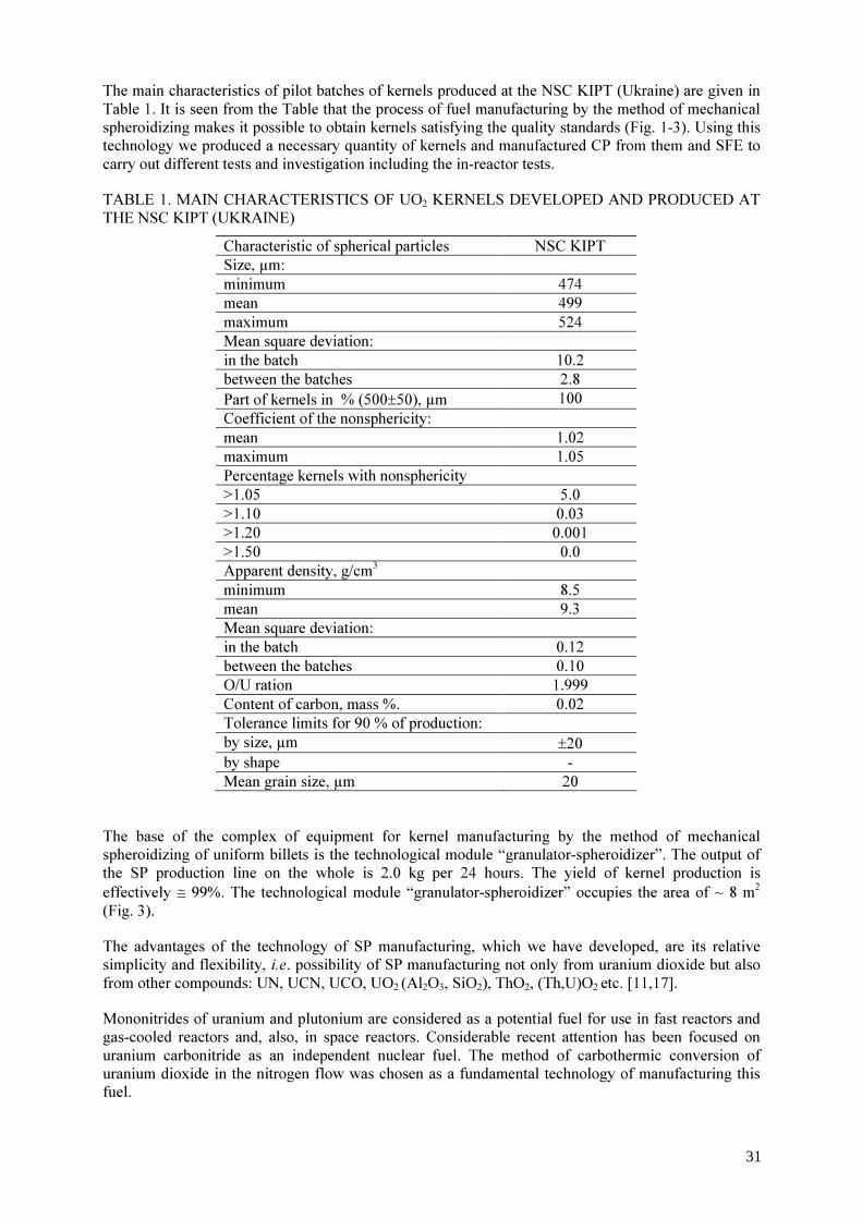
The main characteristics of pilot batches of kernels produced at the NSC KIPT (Ukraine) are given in Table 1. It is seen from the Table that the process of fuel manufacturing by the method of mechanical spheroidizing makes it possible to obtain kernels satisfying the quality standards (Fig. 1-3). Using this technology we produced a necessary quantity of kernels and manufactured CP from them and SFE to carry out different tests and investigation including the in-reactor tests. TABLE 1. MAIN CHARACTERISTICS OF UO2 KERNELS DEVELOPED AND PRODUCED AT THE NSC KIPT (UKRAINE)
Characteristic of spherical particles NSC KIPT Size, µm: minimum 474 mean 499 maximum 524 Mean square deviation: in the batch 10.2 between the batches 2.8 Part of kernels in % (500±50), µm 100 Coefficient of the nonsphericity: mean 1.02 maximum 1.05 Percentage kernels with nonsphericity >1.05 5.0 >1.10 0.03 >1.20 0.001 >1.50 0.0 Apparent density, g/cm3 minimum 8.5 mean 9.3 Mean square deviation: in the batch 0.12 between the batches 0.10 O/U ration 1.999 Content of carbon, mass %. 0.02 Tolerance limits for 90 % of production: by size, µm ±20 by shape - Mean grain size, µm 20
The base of the complex of equipment for kernel manufacturing by the method of mechanical spheroidizing of uniform billets is the technological module “granulator-spheroidizer”. The output of the SP production line on the whole is 2.0 kg per 24 hours. The yield of kernel production is effectively ≅ 99%. The technological module “granulator-spheroidizer” occupies the area of ~ 8 m2
(Fig. 3). The advantages of the technology of SP manufacturing, which we have developed, are its relative simplicity and flexibility, i.e. possibility of SP manufacturing not only from uranium dioxide but also from other compounds: UN, UCN, UCO, UO2 (Al2O3, SiO2), ThO2, (Th,U)O2 etc. [11,17]. Mononitrides of uranium and plutonium are considered as a potential fuel for use in fast reactors and gas-cooled reactors and, also, in space reactors. Considerable recent attention has been focused on uranium carbonitride as an independent nuclear fuel. The method of carbothermic conversion of uranium dioxide in the nitrogen flow was chosen as a fundamental technology of manufacturing this fuel.
31

The processes of producing UN (UCN) in the presence of methane and carbon oxides were investigated at carbothermic conversion of UO2 in nitrogen and nitrogen-hydrogenous atmospheres (P = 0.1 MPa at 1400-1800 °C). The conditions of producing uranium nitride (carbonitride) in the form of powder or compact products were investigated, and the feasibility of direct conversion of UO2 microspheres into UN microspheres was demonstrated (Fig. 4). The heat treatment in a nitrogen-hydrogen atmosphere at 1400-1600 °C ensures an efficient removal of carbon from UCxN1-x with the formation of uranium mononitride. The results of the present studies show that the two-stage process, i.e., carbothermic reduction of UO2 to UCxN1-x in the nitrogen-hydrogen atmosphere with a subsequent hydrogenation, appears to be the most preferable for producing uranium mononitride in the form of compact products, e.g., microspheres. The rate of carbothermic UCxN1-x synthesis grows with an increased porosity of initial UO2 microspheres owing to the arising mechanism of gas-phase transport of carbon. The technology of manufacturing nitride (carbonitride) fuel was developed in the NSC KIPT and the results of its tests, including reactor tests, allow to recommend it for using in nuclear power plants. The outcomes of additional researches will allow to realize potential capabilities of the developed technology for manufacturing the nitride fuel based on the isotope of nitrogen-15 [11]. 2.1.2. Coated particles For deposition of coating layers onto fuel kernels, the specialists of NSC KIPT applied the well-known method of “boiling layer” [13]. The process of manufacturing CP differs from the foreign analogues by the kind of used gases and conditions of protecting layer deposition. In particular, instead of the internal and external dense PyC layers we use combined (PyC + SiC) coatings with a density of ~ 2.4 g/cm3 (this special coating layer is also sometimes called “SiC alloyed PyC”): The conditions of deposition of coatings and their main characteristics are given in Table 2. The data of Table 2 show that in comparison with the known foreign [6,7] prototypes, thickness of the buffer PyC layer in the CP under consideration is decreased approximately by a factor of 2 and the internal and external dense PyC layers are changed by the combined (PyC + SiC) layers with a density ≥ 2.4 g/cm3. This change allowed us to decrease the fission gas release rate in loose particle irradiation tests from circa 6x10⁻⁵ down to 10-6. Besides, the rate of (PyC + SiC) layer deposition is higher by a factor of 3-4 than the rate of dense PyC layer deposition. This factor considerably upgrades the economics of particle manufacture. TABLE 2. DEPOSITION CONDITIONS AND MAIN CHARACTERISTICS OF PROTECTING COATINGS
Characteristics of coatings Coating layer Gas mixture Temperature, C Density, g/cm3 Thickness,
µm PyC buf. PB – Ar 1400 1.1±0.1 40-60 PyCtrans. PB – Ar 1300 1.5±0.1 10-20 PyC+SiC PB – MTCS – Н2 – Ar 1500 ≥ 2.4 50-60 SiC MTCS – Н2 – Ar 1500 ≥ 3.16 60-70 PyC+SiC PB – MTCS – Н2 – Ar 1500 ≥ 2.4 40-50
Note: PB- propane+butane, MTCS- methyltrichlorosilane CH3SiCl3
32

2.1.3. Fabrication of fuel and absorbing elements Fuel particles and commercial-grade graphite are used as basic materials for FE fabrication. An easily removable (no coke residue) plasticizer, e.g., glycerin, oil, is introduced into the graphite powder. The stock obtained is used to mould the FE cladding billets. To mould core billets, the charge material is incorporated with the necessary amount of coated particles. From this charge the billet for a core of 40 mm in diameter is formed. Then the billet of the core and two billets of claddings are formed together. Thus, the spherical billets for fuel elements of 60 mm are made. The diagram of moulding the FE billets is shown in Fig. 5 [6,7,13]. On moulding, we do not set as a goal to obtain a high density of billets. Generally, it is between 1.1 and 1.3 g/cm3 and this ensures a sufficient strength to withstand subsequent technological procedures. The billets, so molded, are placed in close rows in a porous form, then they are filled with a powder of graphite, coke, quarts, etc. (to retain the shape of the products after plasticizer evaporation) and are impregnated in the pyrolysis installations to the density required (usually up to 1.8 to 1.95 g/cm3). After the impregnation procedure is completed, the FE are grinded to get the necessary surface finish (Fig. 6). The fabrication process of absorber elements is the same except that in the core stock incorporated are not fuel particles but B4C powder or any other absorbing material [20]. Compared to the case of spherical FE, the fabrication of FE in the block form (Fig. 7) or rod fuel composites, etc., by the gas-phase technology appears to be simpler. Here, a mixture of fuel particles with a graphite powder is charged into the porous forms made of commercial-grade graphite or carbon cloth. The half-finished products are impregnated with PyC and then their surfaces are machined. 2.2. Manufacture of PyC-bound graphite blocks For GSP 1 production, we also use commercial-grade graphite powders [14]. After sieving, the required, mainly, fine-grained (the particle size being up to 630 µm) fraction is taken. The powder is charged into the porous forms and is compacted by vibration to an apparent density of 0.8 to 1.0 g/cm3, and then is impregnated in pyrolysis installations to a density of 1.7 to 1.95 g/cm3 (1.97 g/cm3
being the upper limit for us). In this way we can produce GSP blocks of different sizes (Fig. 8), ranging from small ones to 2500 mm in length and diameter (in pyrolysis installation GF-3). 2.3. Fabrication of constructions and products from carbon-carbon composites CCC The advantages of volume gas-phase impregnation are most successfully realized when fillers of carbon fibers or fabrics are used. In this case, the moulding of required-size structures is substantially simplified. It is carried out without binders by using such known methods as winding, weaving, etc. The products obtained have a minimum of allowance for subsequent machining or even, after impregnating with PyC, can be used without any surface treatment. By this technology we produce blocks, plates, pipes, cylinders and other structures (Fig. 8), which may have extensive applications in the HTGR core [10]. As mentioned above, we have a possibility of fabricating CCC cylinders up to 2500 mm in diameter and 2600 mm in height (in pyrolysis installation GF-3). Up to now we have had no need of larger sizes, but if necessary, there are no technical or economic barriers to the construction of the 1 GSP is the Russian abbreviation for PyC-bound graphite.
33
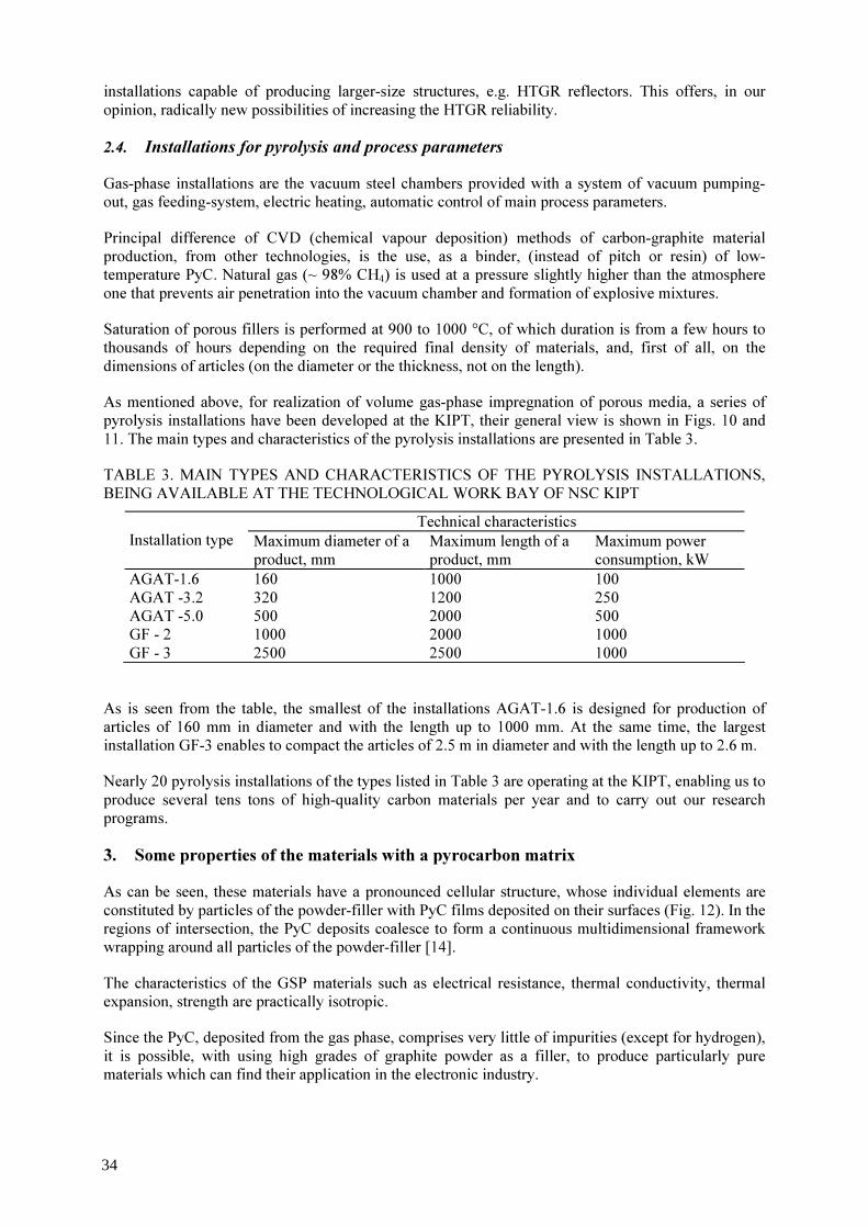
installations capable of producing larger-size structures, e.g. HTGR reflectors. This offers, in our opinion, radically new possibilities of increasing the HTGR reliability. 2.4. Installations for pyrolysis and process parameters Gas-phase installations are the vacuum steel chambers provided with a system of vacuum pumping-out, gas feeding-system, electric heating, automatic control of main process parameters. Principal difference of CVD (chemical vapour deposition) methods of carbon-graphite material production, from other technologies, is the use, as a binder, (instead of pitch or resin) of low-temperature PyC. Natural gas (~ 98% CH4) is used at a pressure slightly higher than the atmosphere one that prevents air penetration into the vacuum chamber and formation of explosive mixtures. Saturation of porous fillers is performed at 900 to 1000 °C, of which duration is from a few hours to thousands of hours depending on the required final density of materials, and, first of all, on the dimensions of articles (on the diameter or the thickness, not on the length). As mentioned above, for realization of volume gas-phase impregnation of porous media, a series of pyrolysis installations have been developed at the KIPT, their general view is shown in Figs. 10 and 11. The main types and characteristics of the pyrolysis installations are presented in Table 3. TABLE 3. MAIN TYPES AND CHARACTERISTICS OF THE PYROLYSIS INSTALLATIONS, BEING AVAILABLE AT THE TECHNOLOGICAL WORK BAY OF NSC KIPT
Technical characteristics Installation type Maximum diameter of a
product, mm Maximum length of a product, mm
Maximum power consumption, kW
AGAT-1.6 160 1000 100 AGAT -3.2 320 1200 250 AGAT -5.0 500 2000 500 GF - 2 1000 2000 1000 GF - 3 2500 2500 1000
As is seen from the table, the smallest of the installations AGAT-1.6 is designed for production of articles of 160 mm in diameter and with the length up to 1000 mm. At the same time, the largest installation GF-3 enables to compact the articles of 2.5 m in diameter and with the length up to 2.6 m. Nearly 20 pyrolysis installations of the types listed in Table 3 are operating at the KIPT, enabling us to produce several tens tons of high-quality carbon materials per year and to carry out our research programs. 3. Some properties of the materials with a pyrocarbon matrix As can be seen, these materials have a pronounced cellular structure, whose individual elements are constituted by particles of the powder-filler with PyC films deposited on their surfaces (Fig. 12). In the regions of intersection, the PyC deposits coalesce to form a continuous multidimensional framework wrapping around all particles of the powder-filler [14]. The characteristics of the GSP materials such as electrical resistance, thermal conductivity, thermal expansion, strength are practically isotropic. Since the PyC, deposited from the gas phase, comprises very little of impurities (except for hydrogen), it is possible, with using high grades of graphite powder as a filler, to produce particularly pure materials which can find their application in the electronic industry.
34
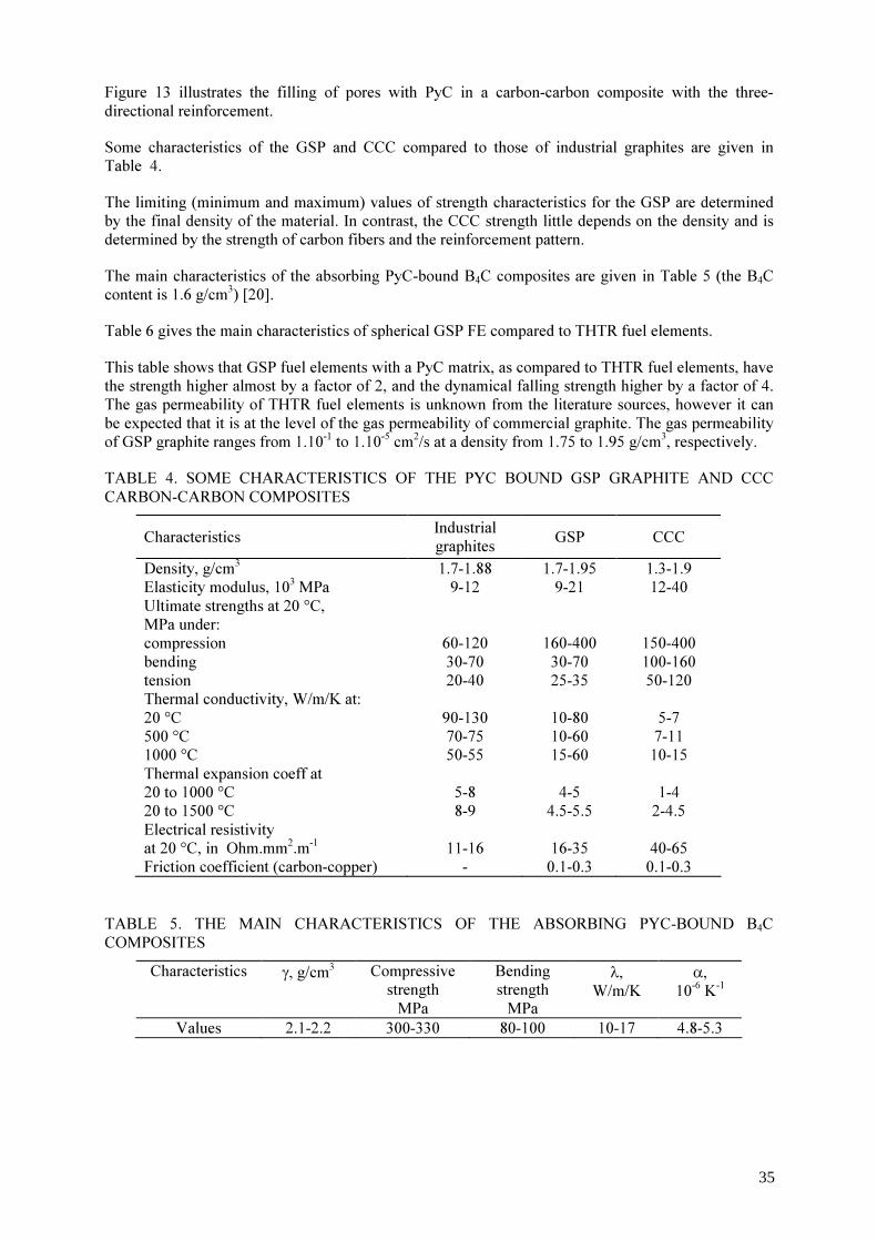
Figure 13 illustrates the filling of pores with PyC in a carbon-carbon composite with the three-directional reinforcement. Some characteristics of the GSP and CCC compared to those of industrial graphites are given in Table 4. The limiting (minimum and maximum) values of strength characteristics for the GSP are determined by the final density of the material. In contrast, the CCC strength little depends on the density and is determined by the strength of carbon fibers and the reinforcement pattern. The main characteristics of the absorbing PyC-bound B4C composites are given in Table 5 (the B4C content is 1.6 g/cm3) [20]. Table 6 gives the main characteristics of spherical GSP FE compared to THTR fuel elements. This table shows that GSP fuel elements with a PyC matrix, as compared to THTR fuel elements, have the strength higher almost by a factor of 2, and the dynamical falling strength higher by a factor of 4. The gas permeability of THTR fuel elements is unknown from the literature sources, however it can be expected that it is at the level of the gas permeability of commercial graphite. The gas permeability of GSP graphite ranges from 1.10-1 to 1.10-5 сm2/s at a density from 1.75 to 1.95 g/cm3, respectively. TABLE 4. SOME CHARACTERISTICS OF THE PYC BOUND GSP GRAPHITE AND CCC CARBON-CARBON COMPOSITES
Characteristics Industrial graphites GSP CCC
Density, g/cm3 1.7-1.88 1.7-1.95 1.3-1.9 Elasticity modulus, 103 MPa 9-12 9-21 12-40 Ultimate strengths at 20 °C, MPa under:
compression 60-120 160-400 150-400 bending 30-70 30-70 100-160 tension 20-40 25-35 50-120 Thermal conductivity, W/m/K at: 20 °C 90-130 10-80 5-7 500 °C 70-75 10-60 7-11 1000 °C 50-55 15-60 10-15 Thermal expansion coeff at 20 to 1000 °C 5-8 4-5 1-4 20 to 1500 °C 8-9 4.5-5.5 2-4.5 Electrical resistivity at 20 °C, in Ohm.mm2.m-1 11-16 16-35 40-65 Friction coefficient (carbon-copper) - 0.1-0.3 0.1-0.3
TABLE 5. THE MAIN CHARACTERISTICS OF THE ABSORBING PYC-BOUND B4C COMPOSITES
Characteristics γ, g/cm3 Compressive strength MPa
Bending strength MPa
λ, W/m/K
α, 10-6 K-1
Values 2.1-2.2 300-330 80-100 10-17 4.8-5.3
35

TABLE 6. THE MAIN CHARACTERISTICS OF SPHERICAL FUEL ELEMENTS Characteristics GSP fuel
elements THTR-300 fuel elements
Graphite matrix density, g/cm3 1.75-1.95 1.72 Graphite matrix strength, MPa under: compression 100 44.7/45.7 bending 45 20.4/18.6 Dynamic elasticity modulus of graphite MPa, х 104 1.0 0.99/1.03 Thermal conductivity at 290 К, W/m/K Without additional heat treatment 50 - With additional heat treatment 70 67/37 ТCLE (290..1270 K), 10-6 K-1 5.0 3.59/3.92 Static strength, in kN ≥ 40 17 Dynamic strength (average number of falls onto the pebble bed from a 4m height without destruction) > 3000 750 Abrasive wear, mg/cm2.g 1-3 3 Degree of anisotropy 1.03-1.05 1.08-1.10
Note: numerator - parallel to the axis of pressing; denominator - perpendicular to this axis. 4. In-reactor test results 4.1. Coated particles In our in-reactor test programms, we nearly always made tests of loose particles in parallel to tests of spherical FE, where CPs of a particular batch were used [9,13,18,19]. In total, by the present time we have tested more than 50 batches of coated particles of different constructions. Coated particles differed in the material of the fuel core (U02, U02 with additions of Al2O3-SiO2, (Th,U)O2, UCN, etc.) and in the construction (thickness, alternation and the number of PyC (PyC- or SiC coatings). In recent years, in the coated particle manufacture we have used a coating from PyC and silicon carbide (PyC+SiC) deposited simultaneously instead of dense PyC layers. In-reactor tests of coated particles were carried out mainly at a temperature of 1250 °C and burnups to 8% fima. General regularities in the behaviour of coated particles under in-reactor irradiation were observed to be the following. We observed no effect of the fuel core material on the gaseous fission product (GFP) release; the latter depends only on the coated particle construction and the quality of protective coatings. No destruction of coated particles was observed during irradiation, even at Tirr = 1600 °C and fuel burnups of 16% fima. The rate of GFP release (R/B) from coated particles ranged from 10-4 to 0.9x10⁻⁶; in recent years its stable value has been at ∼ 10-6. The post-irradiation examinations revealed that the first layer of a low-density PyC nearly always brakes down. In most cases, the PyC layer, following the first layer, showed serious damages. The replacement of dense PyC coatings with combined PyC-SiC coatings has proved to be very efficient. With this replacement and with other conditions remaining the same, the GFP release rate was reduced by factors of 10 to 15. Moreover, the deposition of combined coatings is a simple and economical process as compared to the deposition of high-quality dense PyC coatings.
36

4.2. Spherical fuel and absorbing elements, GSP and CCC (carbon-carbon composites) Investigation of the radiation resistance (more than 130 experiments) of the SP fuel based on UO2, UO2(Al2O3,SiO2), UCN, (Th,U)O2 was carried out in the composition of CP having different design-technological modifications in the state of free charging in the temperature range from 900 to 1600 °C up to burn-up ~ 13,4 % fima, as well as, in the composition of matrix fuel composites, mock-up and full-scale spherical fuel elements from GSP on the base of coated particles having different design-technological modifications in the temperature range from 900 to 1500 °C up to burn-up ~ 13,4% fima and fast (E > 0.1 MeV) neutron fluence up to 3.0.1021 cm-2. Some experiments were performed for fuel burn-up of 30 - 33 % fima, this being a few times higher than the design value [13,17,18]. During in-reactor testing in the experimental range of temperatures and fluences there were not observed any differences in CP of a new structure (PyC+SiC)- SiC-(PyC+SiC), manufactured on the base of developed SP fuel: UO2, UO2(Al2O3,SiO2), UCN, (Th,U)O2. We have carried out long-duration working efficiency tests under irradiation of CP based on carbon-nitride fuel in the composition of SP fuel elements at a temperature 1250 °C up to the burn-up of 18.5 % fima and at a temperature 1500 °C up to the burn-up of 18 % fima. The tests have shown a high working efficiency of the developed type of fuel (R/B no more than 6.0x10⁻⁶ for the I-type CP and 3.5x10⁻⁶ for the III-type CP) that is more than twice higher than the required planned values for the burn-up. The working efficiency of CP based on carbon-nitride fuel in the composition of the full-scale spherical fuel element at 1250 °C up to burn-up of 8.9% fima (campaign VGM – 8.0% fima) was substantiated. The in-reactor service- life tests were performed on the mixed oxide uranium-thorium fuel. Loose particles performed well at an irradiation temperature 1600 °C up to the burnup of 13.4% fima. The performance of particles based on uranium-thorium fuel at 1250 °C up to a burn-up of 9.8% fima was substantiated. As could be expected, the gas release from SFE was always lower than from fuel loose particles of the same batch. In other words, the GSP matrix serves as an additional barrier, which reduced the gas release rate; the efficiency being the greater the higher is the matrix density. Thus, the increase of the GSP density in FE from 1.65 g/cm3 up to 1.85 g/cm3 reduces the gas release by factors of 10 to 20 [8,9]. With a further increase in the density, this effect becomes still more prominent. The gas release from SFE depends also on the thickness of the fuel-free GSP shell. To verify this, we have performed special experiments, namely, in which the UO2 pellets, 3 nm in diameter, were "packed" into GSP shells of different thicknesses and were irradiated at 1100 °C to a fuel burn-up of ∼ 8 % fima. The experiments have shown that with the increase in the thickness of the fuel-free GSP shell from 3 to 7 am, the GPP release rate decreased from 1.3.10-3 down to 5.10-4, i.e., by a factor of 2.6. Figure 14 shows the GFP release from the GSP fuel elements under irradiation at 1250 °C. Here we can see, firstly, positive effects resulting from the replacement of one or two dense PyC layers by combined layers of PyC+SiC deposited simultaneously (see above); and, secondly, jumps in the GFP release rate. These jumps are typical only of the GSP fuel elements. They are always observed after fuel burnups of 4-5% fima and are independent of Tirr, neutron spectrum, fuel enrichment. We attribute the jumps in the GFP release to damages caused by fission fragments and to loss of sealing by thin PyC films (Fig. 15), deposited during FE impregnation with PyC, on the particles of the fissile material, impurities, which cannot be removed, in practice. Figure 15 shows the dimensional changes of spherical fuel and absorbing elements as functions of fast neutron fluence at different irradiation temperatures. The characteristic property in the behaviour of FE, absorbing elements and GSP under irradiation is an insignificant isotropic shrinkage (not above 2%) at fast fluences of (0.5-1.5) x 1021 fn/cm2. The rate of
37

the shrinkage and its absolute values are practically independent of the irradiation temperature. The shrinkage increases with the PyC content in the material. After fluences of 1.5x10² n/cm2 are attained, the shape changes are no longer observed, at least, up to fast fluences of (1-2)x1022 fn/cm2 (the highest fluences attained in our experiments). The strength characteristics of the materials vary little, but they do not deteriorate. On the contrary, they rather show tendency to improvement after irradiation. The thermal conductivity of FE and GSP also slightly increases after irradiation [10]. The results of in-reactor test analysis are used for optimization of main parameters of the fuel:
type of coating structure: (PyC+SiC) - SiC - (PyC+SiC); fuel: UO2, UO2(Al2O3,SiO2), UCN, UN, (Th,U)O2 kernel density - 85 % theoretical density; kernel diameter - 500 µm; (the conditions of manufacturing the fuel having a size ranging from 300 to 1700 µm with a step 100 µm were optimized in the case of necessity)
spread of diameter is ± 20 µm ; nonsphericity is 1.02 (for CP of a new structure the nonsphericity up to 1.05 is permitted); O/U ratio is 1.98-2.00 (for oxide fuel); Coating properties: values of the thickness of CP protecting coatings:
РуСbuf. = 50±10 µm; РуСtrans. = 15±5 µm; (PyC+SiC)intern. = 55±5 µm; SiC = 65±5 µm; (PyC+SiC)extern. = 45±5 µm; density of layers of CP protecting coatings: РуСbuf. : 1.1 g/сm3 ; РуСtrans.: 1.5 g/сm3 ; (PyC+SiC)intern. : 2.4 g/сm3 ; SiC : 3.16 g/сm3 ; (PyC+SiC)extern. : 2.4 g/сm3 .
The spherical absorbing elements,and the absorbing composites based on B4C dispersions in the GSP with a B4C (natural ) content up to 1.6 g/cm3 were also tested in wide ranges of temperatures (from 300 °C to 1200 °C) and fluences (see Fig. 15) [15,20]. 5. Conclusions All the materials have exhibited an extremely high radiation resistance. Even the materials containing 1.6 g/cm3 of B4C, irradiated in the temperature range of 1200 °C to 1250 °C to burn-up of 90% in boron-10 showed dimensional changes of no more than 1%, while it is commonly known that the hot-pressed boron carbide exhibits swelling at a level of 10% for a 10B burn-up of 1%. It should be noted that during irradiation of B4C - base dispersions in the GSP, the damages are mainly caused not by fast neutrons but rather by heavy fragments of He and Li produced on 10B nuclei as a
38
result of (n,α) reactions. In the number of the displacements per atom (dpa), the damage level of the matrix in the B4C - GSP composite is much higher than that one might expect in the most critical HTGR and are higher than that attained in our tests of GSP at fast fluences of (l-2)x1022 n/cm2. Therefore, in our opinion, in the case when GSP is used in the HTGR core, even in the most stressed places of the lateral reflector, there is no problem of its radiation resistance at temperatures at least from 1200 to 1250 °C. The radiation resistance of CCC with a PyC matrix has not been studied so extensively as in the GSP case. Tests were made mainly with 3D-structure composites only at 300 °C and 600 °C to fast fluences of 1021 n/cm2. After irradiation, we investigated dimensional changes of the samples, as well as, changes in strength properties, thermal conductivity and thermal expansion. The behaviour of CCC under reactor irradiation is in many ways similar to the behaviour of GSP (Fig. 17), and the results obtained give us grounds for optimistic estimations of the prospects of these materials in HTGR applications (Fig. 18).
REFERENCES [1] FIALKOV, A.S., Carbon-graphite materials, Energiya, Moscow, (1979), 320 pages (in
Russian). [2] PLATONOV, P.A., SHTROMBAKH, Ya.I., KARPUKHIN, V.I., Radiation effect on
HTGR graphite, Atomno-Vodorodnaya Ehnergetika I Tekhnologiya,, Energoatomizdat publ., Moscow Issue .6 (1984) pp.77-128 (in Russian).
[3] CARLEY – MACAULY, K.W., and MACKENZIE, W., United Kingdom, Patent № 914776, Intern. Class. - C01b, G21, United Kingdom (1963).
[4] BUNDESREPUBLIK DEUTSCHLAND PATENTSCHRIFT N 1203657 (1965). [5] FITZER, F., The future of carbon-carbon composites, Carbon (1987), v.25, № 2, pp.163-
190. [6] IVANOV, V.E., et al., Dispersion fuel and absorbing elements based on pyrocarbon bound
graphite for HTGR, in Proceedings of the International Conference on Radiation Materials Science, Alushta, USSR, 29 May -1 June, 1978), Moscow, TsHIIAI publ., v.6 (1978) pp.308-325 (in Russian).
[7] GURIN, V.A., et al., "Development of monolithic-type pyrocarbon bound fuel and absorber elements for HTGR", in ‘Nuclear-hydrogen energetics and technology, Moscow, Ehnergoatomizdat (1983), Isssue.5, pp.213-225 (in Russian), HTGR Knowledge Base http://www.iaea.org/inisnkm/nkm/aws/htgr/fulltext/iwggcr8_12.pdf
[8] PONOMAREV-STEPNOY, N.N., et. al., Microfuel elements and fuel elements studies with the use of pre-irradiation, in Proc. of International Working Group on Gas Cooled Reactors meeting on ‘Specialists' Meeting on Gas-Cooled reactor fuel development and spent fuel treatment’, Moscow, 18-21 October, 1983, IWRGCR8, pp.212-225, International Atomic Energy Agency, IAEA, Vienna, HTGR Knowledge Base web-page, http://www.iaea.org/inisnkm/nkm/aws/htgr/abstracts/abst_iwggcr8.html
[9] GURIN, V.A., et. al., Radiation resistance of pyrocarbon bonded fuel and absorbing elements for HTGR, In Proc.of IAEA Technical committee meeting on Gas-cooled reactor technology safety and sitting, Dimitrovgrad, USSR, 21-23 June, 1989, IAEA, Vienna, Austria (1990), E-1 http://www.iaea.org/inisnkm/nkm/aws/htgr/abstracts/abst_389_26.html
[10] ZELENSKIY, V.F., et. al., The effect on neutron irradiation on carbon-graphite materials with a pyrocarbon matrix, in Proc. of the International Confernce on Radiation Materials Science, Alushta, USSR, 23-25 May, 1990, Kharkov-1990, MAEhP SSSR, v.3 (1990) pp.160-171 (in Russian).
[11] ODEYCHUK, N.P., High-temperature fuel based on uranium nitride., in Proc. of the fifth International conference "Nuclear power in space", Podolsk, NPO, Luch, (1999), pp.55.
[12] GURIN, V.A., ZELENSKY, V.F., Gas-phase methods of producing carbon and carbon-
39

carbon materials, Voprosy At. Nauki i Tekhniki. Ser. Fiz. Rad. Povrezhden. i Rad. Materialoved., Kharkov, NSC KIPT publ., Issue.3(69),(1998), pp.83-85 (in Russian).
[13] ZELENSKY, V.F., GURIN, V.A., KONOTOP, Yu.F., ODEYCHUK, N.P., et al. Spherical fuel and absorber elements for HTGR. - Vopr. At. Nauki i Tekhn. Ser.: Fiz. Rad. Povrezhden. i Rad. Materialoved., Kharkov, NNTs KhFTI publ., Issue. 4(76) (2000), pp.56-66 (in Russian).
[14] V.F.ZELENSKY, V.A.GURIN, Yu.F.KONOTOP, N.P.ODEYCHUK et al. GSP graphite. - Voprosy At. Nauki i Tekhniki. Ser. Fiz. Rad. Povrezhden. i Rad. Materialoved., Kharkov, NSC KIPT publ., Issue. 4(76) (2000), pp.67-78 (in Russian).
[15] ZELENSKY, V.F., Radiation resistance of absorber composites with a pyrocarbon binder, Proc. of the International Conference on Radiation Materials Science, Alushta, 22-25 May, 1990, Kharkov, KIPT publ., 1991, v.8, pp.68-76 (in Russian).
[16] VOLOSHRHUK, A.J., GURIN, V.A., ODEYCHUK, K.P., CHAIKA, S.S., Preparation of microspherical fuel kernels for high-temperature gas-cooled reactors using mechanical spheroidisation, in Proc. of International Working Group on Gas Cooled Reactors meeting on ‘Specialists' Meeting on Gas-Cooled reactor fuel development and spent fuel treatment’, Moscow, 18-21 Oct., 1983, pp. 133-137, IAEA, Vienna, (1983) HTGR Knowledge Base web-page, http://www.iaea.org/inisnkm/nkm/aws/htgr/abstracts/abst_iwggcr8.html,
[17] ZELENSKY, V.F., et al., Fuel compositions for HTGR, in Proc. of International Conference on Radiation Materials Science Alushta, 22-25 May, 1990, Kharkov, KIPT publ. (1990), v.4, pp.73-82 (in Russian).
[18] ODEYCHUK, N.P., ZELENSKY, V.F., GURIN, V.A., KONOTOP, Yu.F., Some peculiarities of thorium dioxide-based fuel production at NSC KIPT, in IAEA Tecdoc on ‘Thorium fuel utilization: Options and trends. Proceedings of three IAEA meetings held in Vienna in 1997, 1998 and 1999’, IAEA, Vienna, Austria, November IAEA-TECDOC-1319, pp.280-285, IAEA, Vienna (2002),
[19] ODEYCHUK, N.P., LEVENETS, V.V., KRASNORUTSKY, V.S., Advanced methods of process/quality control in nuclear reactor fuel manufacture, in IAEA TECDOC on Advanced methods of process/quality control in nuclear reactor fuel manufacture. Proceedings of a technical committee meeting, Proceedings of a Technical Committee meeting held in Lingen, Germany, 18-22 October 1999, IAEA-TECDOC-1166, Vienna, IAEA (2000), p.79-84.
[20] ODEYCHUK, N.P., ZELENSKY, V.F., GURIN, V.A., KONOTOP, Yu.F., NSC KIPT’s experience in production of absorber materials, composites and products for control mechanisms of various nuclear reactor types, in IAEA TECDOC on Control assembly materials for water reactors: Experience, performance and perspectives, Proceedings of a Technical Committee meeting held in Vienna 12-15 October 1998, IAEA-TECDOC-1132, Vienna, IAEA (2000), pp.113-120.
40

41

42

Fig. 6. Spherical fuel and absorber elements.
Fig. 7. Prismatic fuel and absorber elements.
43
a)
b)
Fig. 8. GSP billets and products: a) Different purpose products ;
b) GSP block, circa 900 mm diameter and circa 2600 mm length (without machining).
44
45
46
47

48
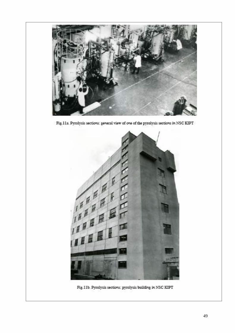
49
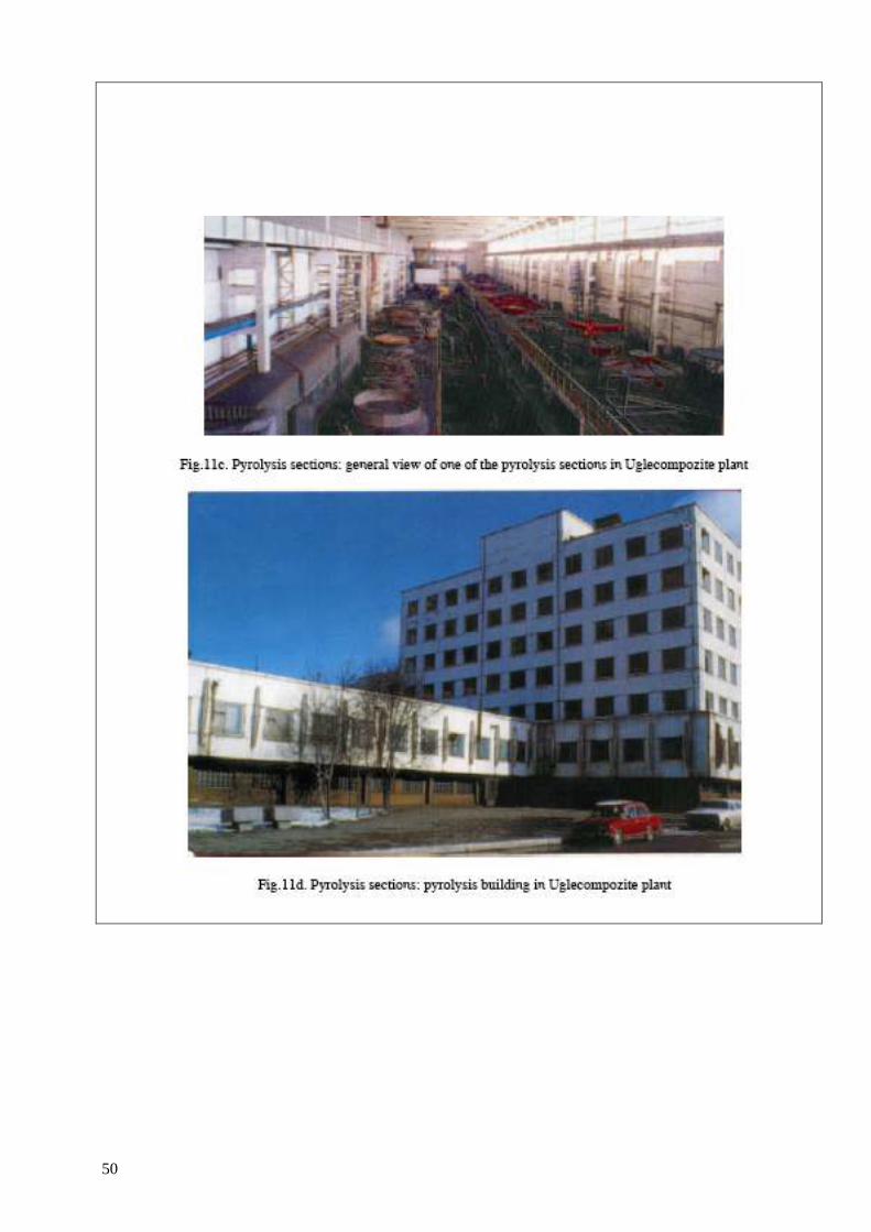
50
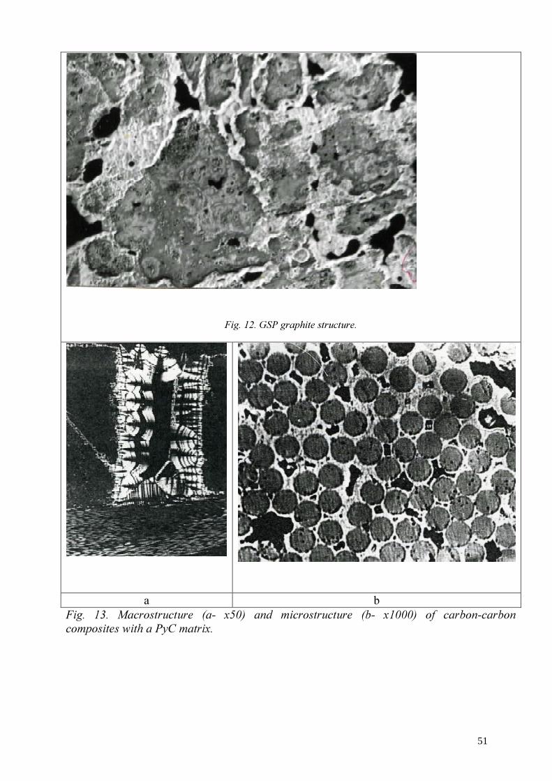
Fig. 12. GSP graphite structure.
a b
Fig. 13. Macrostructure (a- x50) and microstructure (b- x1000) of carbon-carbon composites with a PyC matrix.
51

52

53

Progress in the PBMR fuel development laboratories
F. Venter
NECSA, PBMR Fuel Development Laboratory, Pretoria, South Africa Abstract. The establishment of a pebble bed modular reactor (PBMR) fuel development laboratory at Nuclear Energy Corp. of South Africa (NESCA) is well advanced. The laboratory includes all the facilities required to manufacture uranium dioxide kernels, TRISO coated particles and PBMR spherical fuel elements in accordance with specifications, as well as a QC laboratory to perform the chemical, physical and dimensional tests necessary to control the manufacturing processes and to verify conformance to specified requirements. The latest German HTR - TRISO fuel manufacturing technology has been reproduced on laboratory scale, in advance of construction and start-up of the PBMR fuel plant. The purpose of the laboratory is to develop and validate the quality control (QC) methods, select and qualify material suppliers, gain experience and understanding of the manufacturing processes, and manufacture coated particles and fuel elements for testing and characterization of product as required by PBMR. Conforming UO2 kernels have been made in kilogram quantities. A laboratory CVD (chemical vapor deposition) furnace with a capacity of 1kg UO2 is being used to study TRISO coating parameters systematically. Matrix material has been manufactured in the laboratory and graphite sphere samples pressed, carbonized and annealed. The majority of the methods needed for QC in the future fuel plant have been installed and validated. The remaining QC methods will be available for the development work over the coming months. An overview of the available and planned laboratory development facilities and work will be given.
1. Introduction The pebble bed modular reactor (PBMR) fuel development laboratories at NESCA’s Pelindaba site include the following laboratory scale facilities for development of the expertise required to manufacture PBMR Fuel:
• The kernel laboratory for uranium dioxide kernels; • The coating laboratory for TRISO coated particles; • The graphite laboratory for PBMR spherical fuel elements (fuel spheres); and • The QC laboratory to perform the prescribed chemical, physical and dimensional
tests. This paper provides an overview of the development facilities and work, with emphasis on progress made during the last year. 2. Background The following background is provided in order to put the purpose and objectives of the laboratory work into perspective:
• PBMR fuel configuration; • PBMR pilot fuel plant; and • Manufacturing technology basis.
2.1. PBMR fuel configuration The PBMR fuel is based on TRISO coated particles with low-enriched uranium (LEU) which are contained in spherical fuel elements, as was used in Germany.
54

2.2. PBMR pilot fuel plant The pilot fuel plant will be constructed in the fuel buildings at Necsa which were previously used for manufacture of PWR fuel for Koeberg. The capacity of the pilot fuel plant will be about 270 000 fuel spheres per annum. The pilot fuel plant is currently in the detailed design stage. Key programme milestones include the following:
• Plant installation and cold commissioning (without uranium) complete:
January 2007
• Manufacturing test programme (hot commissioning with uranium) complete:
January 2008
• Qualification lot fuel (enriched uranium) ready for taking of samples for irradiation testing:
April 2008
• Start of fuel production:
May 2008
• Reactor load date:
April 2010
2.3. Manufacturing technology basis The reference fuel is the latest LEU UO2 TRISO fuel made in Germany, and PBMR has access to the documented German HTR fuel manufacturing know-how. This includes the following documents, amongst others:
• Specifications for direct materials (matrix graphite constituents); • Specifications for products and intermediate products; • Testing and acceptance requirements; • Fabrication and inspection procedures; • Product information; and • Plant licensing information.
The above-mentioned documentation has been used to draw up PBMR fuel technical package documents that include product, inspection and material specifications. The fuel technical package documents include the same values and/or limits of quantifiable product characteristics as the reference fuel. The PBMR fuel manufacturing process steps and principles have been specified to be the same as those that were used in Germany. The QC of PBMR fuel will be applied to the same parameters as those of reference fuel. The previous material suppliers to the German HTR programme can still supply natural graphite powder, electro-graphite powder and phenolic resin in accordance with the reference specifications. 3. Purpose of the laboratory work The purpose of the laboratory work is to accomplish the following, amongst other things, in advance of commissioning of the pilot fuel plant:
• Reproduce on laboratory scale the latest German HTR TRISO fuel manufacturing technology (the reference fuel for PBMR) and thereby gain experience and understanding of the processes and materials that will be used in the pilot fuel plant;
55

• Develop the QC test methods, perform capability studies and qualify the QC test methods in order to provide a QC testing service for both the process development work and later for the pilot fuel plant;
• Establish methods to process the effluent and waste streams; • Establish and qualify suppliers of materials; • Produce product for early characterization tests, including preliminary irradiation
tests; • Support the design of the pilot fuel plant; and • Train core staff for the pilot fuel plant.
Thereafter the laboratories and the specialist staff will focus on supporting the hot commissioning and qualification of the pilot fuel plant. 4. Kernel laboratory The laboratory kernel production facility is based on the same process outline and process principles as the reference technology for the external gelation process, as well as the same process parameter values but with changes as necessary to accommodate the laboratory-scale equipment. The process outline for kernel production is shown in Fig. 1. Over the past 3 years the technology has been fully established to manufacture on laboratory scale small amounts of sintered kernels that conform to specification values. To date about 260 casting runs have been carried out, containing about 120 kg of depleted uranium. About 50 kg of UO2 kernels have been produced during the past year for QC testing and trial runs in the existing laboratory coater. Over the past year the main emphasis has been to improve the process set-up and at the same time produce sintered UO2 kernels for coating trials. The process changes have been aimed at:
• Optimizing the process parameters, with due consideration of the German HTR fuel manufacturing experience;
• Reviewing and improving the engineered safety conditions in the facility; and • Increasing the manufacturing capacity in the facility from 1 kg to 2 kg of UO2
kernels per week. The capacity will soon be further increased to 5 kg per week. A new 4-nozzle casting column has been designed, built and commissioned to increase the production rate in the laboratory. After commissioning, 68 runs have been carried out on the new casting column to optimize process parameters and to produce feedstock for coating trials. The old single nozzle casting column will also be used for limited parameter testing. The vibration table for sorting of odd-shaped kernels has been modified, commissioned and operational parameters established. Sintered kernels can now be sorted (after sieving). The numerous process improvements and optimizations carried out during the past year have included the following:
• Increasing the capacity of the casting solution make-up equipment; • Better control of pre-neutralization of the uranyl nitrate solution; • Improved control of the concentration of NH3 in the precipitation solution
and optimization of the concentration in the ageing solution; • Optimization of the calcining temperature-time programme; and
56

• Improved engineered safety of the facilities, processes and handling.
5. Coating laboratory The four coating layers are deposited on kernels in a heated furnace by a process called chemical vapour deposition (CVD). A CVD laboratory coater was designed and constructed at Necsa prior to access being gained to the reference technology. The laboratory coater was designed for a 1 kg UO2 charge and not 5 kg UO2 as for a production coater. The process outline to coat kernels with the 4 layers is shown in Fig. 2. Over the past three years the know-how required to operate and maintain the CVD coater has been fully established. 121 coater runs have been carried out; 18 runs using alumina kernels, 40 runs using stabilized zirconia kernels, and 63 runs using UO2 kernels. Over the past year the laboratory coater has been extensively modified to:
• Flatten the axial temperature profile in the furnace. A full temperature profile analysis showed that the profile was much better than the profiles previously measured on the laboratory coater and was similar to that which had been obtained on the German reference coaters;
• Further improve the gas distribution; • Provide more flexibility in the coater control program; and • Improve the engineered safety of the facilities, processes and handling.
After recommissioning of the modified laboratory coater, 18 full coater runs have been carried out to establish the process parameter values and to produce product for development of the QC test methods and the fuel sphere manufacturing methods. A vibrating sieve system has been fully commissioned and operating parameters determined. A vibration table to remove odd-shaped particles is being designed. A particle cracker to remove the coatings from coated particles, and so recover kernels for re-use in further coater runs, has been designed, built and tested. Good recoveries of unbroken UO2 kernels have been demonstrated, but practical methods to remove shards from the recovered product are still being evaluated. The thicknesses of all four coating layers, the anisotropy factors of the two dense pyrolytic carbon layers, and the densities of the dense pyrolytic carbon and SiC layers have been mostly within the specification values. The density of the low-density buffer layer has, for the first time, been within specification. A production-scale CVD coater (5 kg UO2 charge) has been designed over the past year. The production-scale coater is equivalent to the German HTR reference technology and is representative of the coaters to be installed in the pilot fuel plant. The coater is being manufactured and the area in the existing building is being prepared. The plan is to install and commission the production coater by the end of October 2005. Thereafter the production coater will be hot commissioned and tests carried out until conforming product can be manufactured routinely. The objective is to optimize the coating process parameters by mid 2006. 6. Graphite laboratory The laboratory facility for the preparation of matrix graphite powder, overcoating of coated particles, and manufacture of fuel spheres is based on the same principle process steps as those used in Germany. The process outline to manufacture fuel spheres is shown in Fig. 3.
57
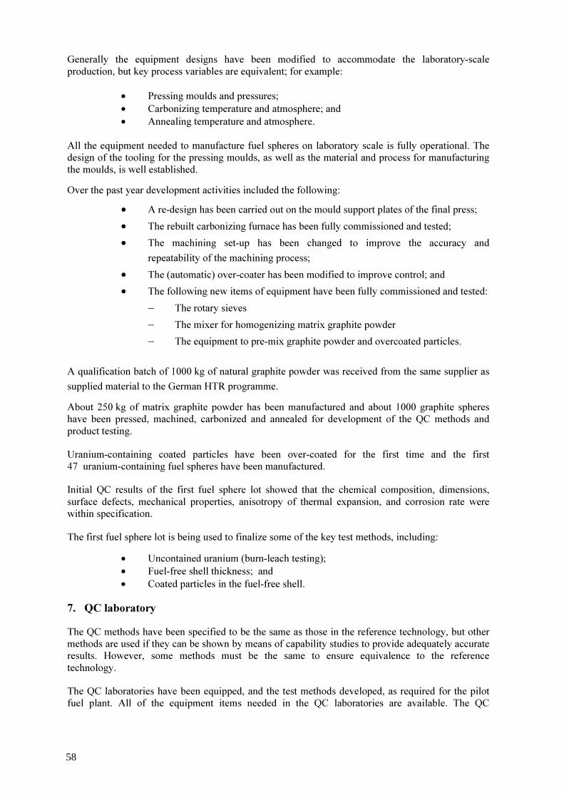
Generally the equipment designs have been modified to accommodate the laboratory-scale production, but key process variables are equivalent; for example:
• Pressing moulds and pressures; • Carbonizing temperature and atmosphere; and • Annealing temperature and atmosphere.
All the equipment needed to manufacture fuel spheres on laboratory scale is fully operational. The design of the tooling for the pressing moulds, as well as the material and process for manufacturing the moulds, is well established. Over the past year development activities included the following:
• A re-design has been carried out on the mould support plates of the final press; • The rebuilt carbonizing furnace has been fully commissioned and tested; • The machining set-up has been changed to improve the accuracy and
repeatability of the machining process; • The (automatic) over-coater has been modified to improve control; and • The following new items of equipment have been fully commissioned and tested:
− The rotary sieves − The mixer for homogenizing matrix graphite powder − The equipment to pre-mix graphite powder and overcoated particles.
A qualification batch of 1000 kg of natural graphite powder was received from the same supplier as supplied material to the German HTR programme. About 250 kg of matrix graphite powder has been manufactured and about 1000 graphite spheres have been pressed, machined, carbonized and annealed for development of the QC methods and product testing. Uranium-containing coated particles have been over-coated for the first time and the first 47 uranium-containing fuel spheres have been manufactured. Initial QC results of the first fuel sphere lot showed that the chemical composition, dimensions, surface defects, mechanical properties, anisotropy of thermal expansion, and corrosion rate were within specification. The first fuel sphere lot is being used to finalize some of the key test methods, including:
• Uncontained uranium (burn-leach testing); • Fuel-free shell thickness; and • Coated particles in the fuel-free shell.
7. QC laboratory The QC methods have been specified to be the same as those in the reference technology, but other methods are used if they can be shown by means of capability studies to provide adequately accurate results. However, some methods must be the same to ensure equivalence to the reference technology. The QC laboratories have been equipped, and the test methods developed, as required for the pilot fuel plant. All of the equipment items needed in the QC laboratories are available. The QC
58

laboratories routinely perform the QC tests required by the process development laboratories. Necsa’s analytical laboratories are being used for isotopic and impurity analyses of uranic materials. 3994 QC tests have been carried out over the past 12 months in support of the process development work. Apart from this, good progress has also been made with respect to establishing new test facilities and methods. Approximately 90% of experimental work required to establish the 67 main product QC tests required for PBMR fuel has been completed. The development work during the past year has included the completion of the following QC test facilities and methods:
• A semi-automated sphere drop test facility; • A comprehensive X-ray fuel sphere inspection facility with full tomographic
reconstruction capability; • A sphere corrosion test facility; • A dilatometer for determining the anisotropy of thermal expansion of spheres • A new universal tensile testing machine (for, amongst other things, determining
the crushing strength of spheres); and • A simultaneous thermal analyser (for determining the stoichiometry of uranium
oxides and the analysis of moisture content in uranium oxide powder). The following facilities have been commissioned and experimental development work on the test methods has progressed well:
• Particle sorting tables (for QC purposes); • A burn-leach test facility as well as the associated methods for determination of
low levels of uranium; and • A laser flash thermal diffusivity measuring device (for determining thermal
conductivity).
A micro-radiography facility has been set up and tests to optimize the test parameters have started. 8. Staffing The present numbers of full-time staff in the PBMR fuel development group in the laboratories at Necsa are as follows:
FUNCTION No. OF PERSONS Kernel laboratory 6 Coating laboratory 6 Fuel sphere laboratory 6 QC laboratory 11 Buildings and infrastructure 9 Management and staff specialists 5 Administrative and secretarial 4 TOTAL 47
59

9. Conclusions Reproducing the latest German HTR TRISO fuel manufacturing technology, and establishment of a QC laboratory, is well advanced. A production coater (5 kg UO2 charge) has been designed and will be installed, commissioned and tested by mid 2006. After commissioning and testing of the production-scale coater, the laboratory fuel manufacturing facilities will be a good simulation of the processes to be applied in the PBMR pilot fuel plant. Development of the manufacturing and QC processes has progressed significantly over the past year and good product should be available towards mid 2006 for characterization and preliminary irradiation testing. By the start of the manufacturing test programme (hot commissioning with uranium) in the PBMR pilot fuel plant (February 2007):
• Fuel plant staff will have gained considerable experience and understanding of the processes and materials that will be used in the fuel plant;
• The coating process parameters will have been optimized; • The QC test equipment and methods will be available and qualified; • Suppliers of materials will have been established and qualified; and • The core staff for the fuel plant will have been trained.
60

FIG. 1. UO2 kernel production.
Ammonium hydroxide solution
Water
Alcohol
CALCINE
REDUCE & SINTER
Remove NH4NO3, NH4OH and additives
Remove moisture
Remove residual moisture and vaporise remaining alcohol
In hydrogen up to 1600°C Reduce UO3 to UO2Form dense, stoichiometric UO2
AGE
DRY
WASH
WASH
PREPARE CASTING SOLUTION
CAST ADU MICROSPHERES
U3O8 powder
Nitric acid
Ammonium hydroxide
Organic additives
PREPARE URANYL NITRATE SOLUTION
SIEVE
In air up to 430°C Crack organic additiveConvert ADU to UO3
QC TESTS
Remove over- and undersize particles
Remove odd-shaped particlesSORT(VIBRATION TABLE)
STOREUO2 KERNELS
Ammonium hydroxide solution
Ammonium hydroxide solutionAmmonium hydroxide solution
WaterWater
AlcoholAlcohol
CALCINECALCINE
REDUCE & SINTERREDUCE & SINTER
Remove NH4NO3, NH4OH and additives
Remove moisture
Remove residual moisture and vaporise remaining alcohol
In hydrogen up to 1600°C Reduce UO3 to UO2Form dense, stoichiometric UO2
AGE
DRY
WASH
WASH
AGE
DRY
WASH
WASH
PREPARE CASTING SOLUTION
PREPARE CASTING SOLUTION
CAST ADU MICROSPHERESCAST ADU
MICROSPHERES
U3O8 powder
Nitric acidNitric acid
Ammonium hydroxideAmmonium hydroxide
Organic additivesOrganic additives
PREPARE URANYL NITRATE SOLUTIONPREPARE URANYL NITRATE SOLUTION
SIEVESIEVE
In air up to 430°C Crack organic additiveConvert ADU to UO3
QC TESTSQC TESTS
Remove over- and undersize particles
Remove odd-shaped particlesSORT(VIBRATION TABLE)
SORT(VIBRATION TABLE)
STOREUO2 KERNELS
STOREUO2 KERNELS
Ammonium hydroxide solutionAmmonium hydroxide solution
61

FIG. 2. Coating process.
DEPOSIT BUFFER LAYER
DEPOSIT OUTER
DEPOSIT INNER
DEPOSIT SiC LAYER
SIEVE
STORE COATED PARTICLES
QC TESTS
CVD FURNACE
AcetyleneArgon
PropyleneAcetyleneArgon
MethyltrichlorosilaneHydrogen
PropyleneAcetyleneArgon
UO2 KERNELS
SORT (VIBRATION TABLE)
Porous low-density carbon
Dense, isotropic silicon carbide
Remove over- and undersize particles
Remove odd-shaped particles(To be installed)
PyC LAYER
High-density pyrolytic carbon
High-density pyrolytic carbon
PyC LAYER
62

FIG. 3. Fuel sphere (FS) manufacturing.
OVERCOAT THE COATED PARTICLES
WITH FINE MGP
CORE MOULD MANUFACTURE
FS MOULD MANUFACTURE MGP
MIX IN CORE MOULD
PRESS FUEL CORE IN MOULD
PACK FUEL-FREE SHELL OF MGP
AROUND FS CORE
PRE-MIX
PRESS COMPLETE FS IN MOULD
MACHINE FS TO SIZE
CARBONISE
ANNEAL
STORE FS
QC TESTS
Argon 800°C
Vacuum 1950°C
FINE-MILLMANUFACTURE
MATRIX GRAPHITE POWDER (MGP)
OVERCOAT THE COATED PARTICLES
WITH FINE MGPOVERCOAT THE
COATED PARTICLES WITH FINE MGP
CORE MOULD MANUFACTURECORE MOULD MANUFACTURE
FS MOULD MANUFACTURE
FS MOULD MANUFACTURE MGPMGP
MIX IN CORE MOULD
MIX IN CORE MOULD
PRESS FUEL CORE IN MOULD
PRESS FUEL CORE IN MOULD
PACK FUEL-FREE SHELL OF MGP
AROUND FS COREPACK FUEL-FREE SHELL OF MGP
AROUND FS CORE
PRE-MIXPRE-MIX
PRESS COMPLETE FS IN MOULD
PRESS COMPLETE FS IN MOULD
MACHINE FS TO SIZE
MACHINE FS TO SIZE
CARBONISECARBONISE
ANNEALANNEAL
STORE FSSTORE FS
QC TESTSQC TESTS
Argon 800°C
Vacuum 1950°C
FINE-MILLFINE-MILLMANUFACTURE
MATRIX GRAPHITE POWDER (MGP)MANUFACTURE
MATRIX GRAPHITE POWDER (MGP)
63

PHOTOGRAPH 1. Casting columns
PHOTOGRAPH 2. Rotary AWD vessel
64

PHOTOGRAPH 3. Kernel micrographs
Cast
Aged
Dried
Calcined
Sintered
65

PHOTOGRAPH 4. Laboratory CVD coater
PHOTOGRAPH 5. Coated particle ceramograph
66
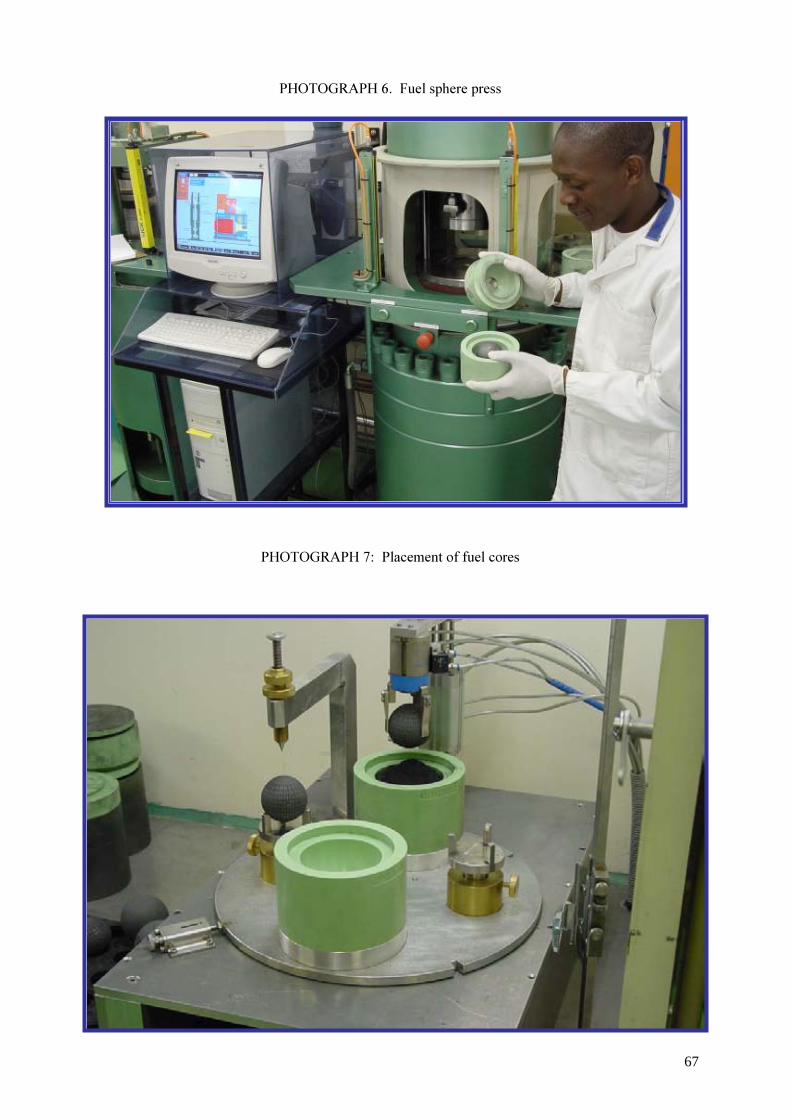
PHOTOGRAPH 6. Fuel sphere press
PHOTOGRAPH 7: Placement of fuel cores
67

PHOTOGRAPH 8. Particle size and diameter analyser
PHOTOGRAPH 9. Optical anisotropy factor determination system
68
Overview on HTR coated particle fuels development in Russia
A.S. Chernikov, S.D. Kurbakov SIA–Lutch, Podolsk, Moscow Region, Russian Federation
Abstract. A short information on Russian investigations in the field of tri-isotropic (TRISO) coated particle fuels development for high temperature reactor system (HTR) with pebble bed core (VGR – 50, VG – 400, VGM reactors) is presented. Requirements for UO2 kernels with a 500 µm diameter and for coatings on them as well as the achieved characteristics of coated particle fuels are discussed. In the report requirements for coated particle fuels on the base of kernels of 200 µm in diameter for Modular High-Temperature Gas-cooled Reactor (MHTGR) with a prismatic core are also described. The first results of investigations on manufacture of such coated particle fuels in the laboratory scale are given.
1. Introduction The concept of pebble bed cores of high temperature gas cooled reactor system namely VGR-50, VG-400 and VGM reactors designed in Russia in 1970-1980 was based on the use of spherical fuel elements 60 mm in diameter in which particles of uranium dioxide 500 microns in diameter are coated by pyrocarbon (PyC) and silicon carbide (SiC) layers and evenly spaced in a graphite matrix. Such fuel elements requirements and service conditions are presented in Table 1. The analysis of fuel element operating conditions has allowed to determine the basic fuel kernel and coated fuel particle requirements. TABLE 1. SPHERICAL FUEL ELEMENTS SPECIFICATIONS AND SERVICE CONDITIONS OF RUSSIAN HTGR No Characteristics VGR-50 VG-400 VGM
modular pebble-bed
1 Fast neutron fluence (E>0.18Mev)·1021 cm-2
1.2 1.7 1.3
2 Burnup, % fima 10-15 ≤8 10 (max) 3 Maximal temperature of fuel, °C
• Nominal • Accident
1300 1600(5-10h)
1250 1600(5-10h)
1250 1600(100h)
4 Operating time, h 5400 8200 23 040 5 Number of thermal cycles during lifetime ≤2000 ≤200 up to 15 6 235U content in a fuel element, g 0.5 0.4 0.56 7 Enrichment, % 21 6.5 8 8 Compressive stress, kN ≤15 ≤20 ≤20 9 Allowable decrease of a fuel element diameter, mm ≤3 ≤0.6 ≤0.6 10 Average erosion rate, mg/cm2·h ≤4·10-2 ≤6·10-3 - 11 Permissible fission gas products release (R/B) ≤10-4 ≤10-5 ≤10-5
2. Fuel kernels High stipulations to fission product retention in coated fuel particles dictate corresponding initial kernel specifications (Table 2).
69
TABLE 2. URANIUM DIOXIDE FUEL KERNEL SPECIFICATIONS (DIAMETER 500 MICRONS)
Characteristic Value Density, g/cm3 > 10.4 Coefficient of non-sphericity ≤ 1.05 Deviation from the nominal diameter, µm ± 50
Investigations have shown that the quality of fuel kernels depends not only on coefficient of non-sphericity, size, deviation from nominal size, density, and grain and pores size, but also on distribution of the latter in a volume, surface relief, as well as on phase and chemical composition. Fluctuations of these characteristics essentially influence the quality of deposited protective coatings and eventually the key parameter of coated fuel particle quality - retention of fission products. Various ways of fuel kernel manufacture have been investigated taking into consideration of these specifications: pelletizing of uranium dioxide powder or preliminary compacted powder and milled of them for preparations into spherical particles with use of vibration, as well as ways based on the physicochemical effect of surface tension on drop hardening: sol-gel process and spheroidizing by slip casting method. The best compliance of complex of characteristics with requirements (Table 3) was achieved with use of the last two methods. Fuel kernels have acceptable uniformity of size 500 ± 50 micron, mean non-sphericity coefficient ≤1.05, density close to theoretical and grain size 5 - 40 microns in dependence on heat treatment temperature. TABLE 3. BASIC CHARACTERISTICS OF UO2 KERNELS MANUFACTURED BY PHYSICOCHEMICAL METHODS
Slip method Sol-gel process Characteristic x x
S xS x xS xS
Size, µm 499 5 24 497 3 14 Coefficient of non-sphericity 1.05 0.03 1.02 0.01 Fraction of kernels with non-sphericity coefficient, %: > 1.0 - - - 1.6 - - > 1.1 7.3 - - 0 - - Density, g/cm3: geometrical 10.6 0.2 - 10.6 0.2 - pycnometric 10.6 0.06 - 10.6 0.06 - O/U ratio ≤2.00
4 - - ≤2.005 - -
Mass fraction of carbon, % ≤0.05 - - ≤0.01 - - 3. Coated fuel particles The coated fuel particle design (Table 4) accepted in the Russian projects have been unified for all spherical fuel elements based on the calculation and experimental researches in which the basic operational factors (fission gas pressure, anisotropic irradiation-induced dimensional changes of coating layers, creep, thermal stresses) were taken into account. Realization of required coated fuel particle characteristics has demanded performance of a complex research on thermodynamics and kinetics of: i) hydrocarbon pyrolysis (acetylene, methane, propylene) for deposition of PyC; ii) chlorine derivative silane and silicon tetrachloride for deposition of SiC, as well as; iii) development of methods and means of quality control. Coating deposition is carried out in a fluidized-bed apparatus with conic gas distribution device. Crystal lattice parameters, macro- and micro-structure, anisotropy (for high density PyC coating), density and other characteristics vs. pyrolysis conditions in a fluidized bed were investigated as a function of temperature, concentration of reagents, gas mixture flow, modes of fluidizing, etc.
70
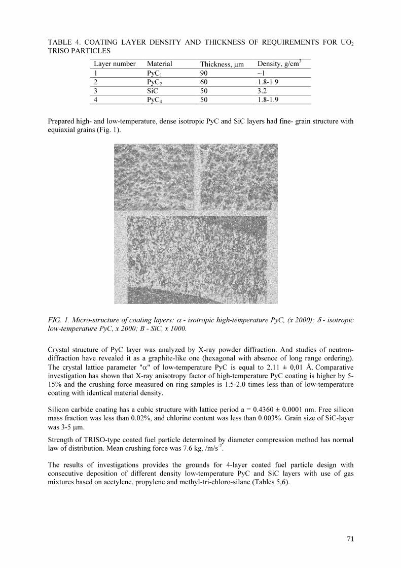
TABLE 4. COATING LAYER DENSITY AND THICKNESS OF REQUIREMENTS FOR UO2 TRISO PARTICLES Layer number Material Thickness, µm Density, g/cm3 1 РуC1 90 ~1 2 РуC2 60 1.8-1.9 3 SiC 50 3.2 4 PуC4 50 1.8-1.9
Prepared high- and low-temperature, dense isotropic PyC and SiC layers had fine- grain structure with equiaxial grains (Fig. 1). FIG. 1. Micro-structure of coating layers: α - isotropic high-temperature PyC, (x 2000); δ - isotropic low-temperature PyC, x 2000; B - SiC, x 1000. Crystal structure of PyC layer was analyzed by X-ray powder diffraction. And studies of neutron-diffraction have revealed it as a graphite-like one (hexagonal with absence of long range ordering). The crystal lattice parameter "α" of low-temperature PyC is equal to 2.11 ± 0,01 Å. Comparative investigation has shown that X-ray anisotropy factor of high-temperature PyC coating is higher by 5-15% and the crushing force measured on ring samples is 1.5-2.0 times less than of low-temperature coating with identical material density. Silicon carbide coating has a cubic structure with lattice period a = 0.4360 ± 0.0001 nm. Free silicon mass fraction was less than 0.02%, and chlorine content was less than 0.003%. Grain size of SiC-layer was 3-5 µm. Strength of TRISO-type coated fuel particle determined by diameter compression method has normal law of distribution. Mean crushing force was 7.6 kg. /m/s-2. The results of investigations provides the grounds for 4-layer coated fuel particle design with consecutive deposition of different density low-temperature PyC and SiC layers with use of gas mixtures based on acetylene, propylene and methyl-tri-chloro-silane (Tables 5,6).
71
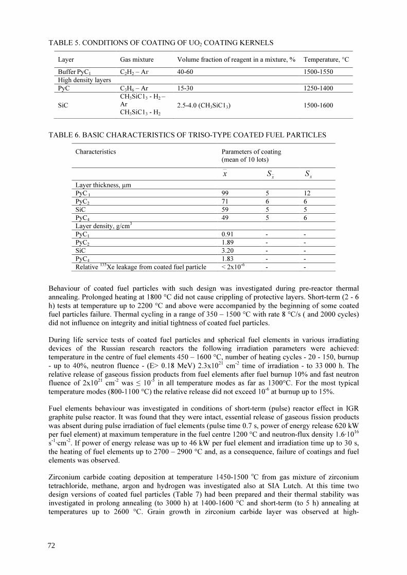
TABLE 5. CONDITIONS OF COATING OF UO2 COATING KERNELS Layer Gas mixture Volume fraction of reagent in a mixture, % Temperature, °C Buffer РyC1 C2Н2 – Аг 40-60 1500-1550 High density layers РуC С3Н6 – Аr 15-30 1250-1400
SiC СН3SiС13 - Н2 – Ar СН3SiС13 - Н2
2.5-4.0 (СН3SiС13) 1500-1600
TABLE 6. BASIC CHARACTERISTICS OF TRISO-TYPE COATED FUEL PARTICLES
Characteristics Parameters of coating (mean of 10 lots)
x xS xS
Layer thickness, µm PyC 1 99 5 12 РуС2 71 6 6 SiC 59 5 5 РуС4 49 5 6 Layer density, g/cm3 РуС1 0.91 - - PуC2 1.89 - - SiC 3.20 - - РуС4 1.83 - - Relative 135Хе leakage from coated fuel particle < 2x10⁻⁶ - -
Behaviour of coated fuel particles with such design was investigated during pre-reactor thermal annealing. Prolonged heating at 1800 °C did not cause crippling of protective layers. Short-term (2 - 6 h) tests at temperature up to 2200 °C and above were accompanied by the beginning of some coated fuel particles failure. Thermal cycling in a range of 350 – 1500 °C with rate 8 °C/s ( and 2000 cycles) did not influence on integrity and initial tightness of coated fuel particles. During life service tests of coated fuel particles and spherical fuel elements in various irradiating devices of the Russian research reactors the following irradiation parameters were achieved: temperature in the centre of fuel elements 450 – 1600 °C, number of heating cycles - 20 - 150, burnup - up to 40%, neutron fluence - (Е> 0.18 MeV) 2.3x1021 cm-2 time of irradiation - to 33 000 h. The relative release of gaseous fission products from fuel elements after fuel burnup 10% and fast neutron fluence of 2x1021 cm-2 was ≤ 10-5 in all temperature modes as far as 1300°C. For the most typical temperature modes (800-1100 °C) the relative release did not exceed 10-6 at burnup up to 15%. Fuel elements behaviour was investigated in conditions of short-term (pulse) reactor effect in IGR graphite pulse reactor. It was found that they were intact, essential release of gaseous fission products was absent during pulse irradiation of fuel elements (pulse time 0.7 s, power of energy release 620 kW per fuel element) at maximum temperature in the fuel centre 1200 °C and neutron-flux density 1.6·1016 s-1·cm-2. If power of energy release was up to 46 kW per fuel element and irradiation time up to 30 s, the heating of fuel elements up to 2700 – 2900 °C and, as a consequence, failure of coatings and fuel elements was observed. Zirconium carbide coating deposition at temperature 1450-1500 oС from gas mixture of zirconium tetrachloride, methane, argon and hydrogen was investigated also at SIA Lutch. At this time two design versions of coated fuel particles (Table 7) had been prepared and their thermal stability was investigated in prolong annealing (to 3000 h) at 1400-1600 °C and short-term (to 5 h) annealing at temperatures up to 2600 °C. Grain growth in zirconium carbide layer was observed at high-
72
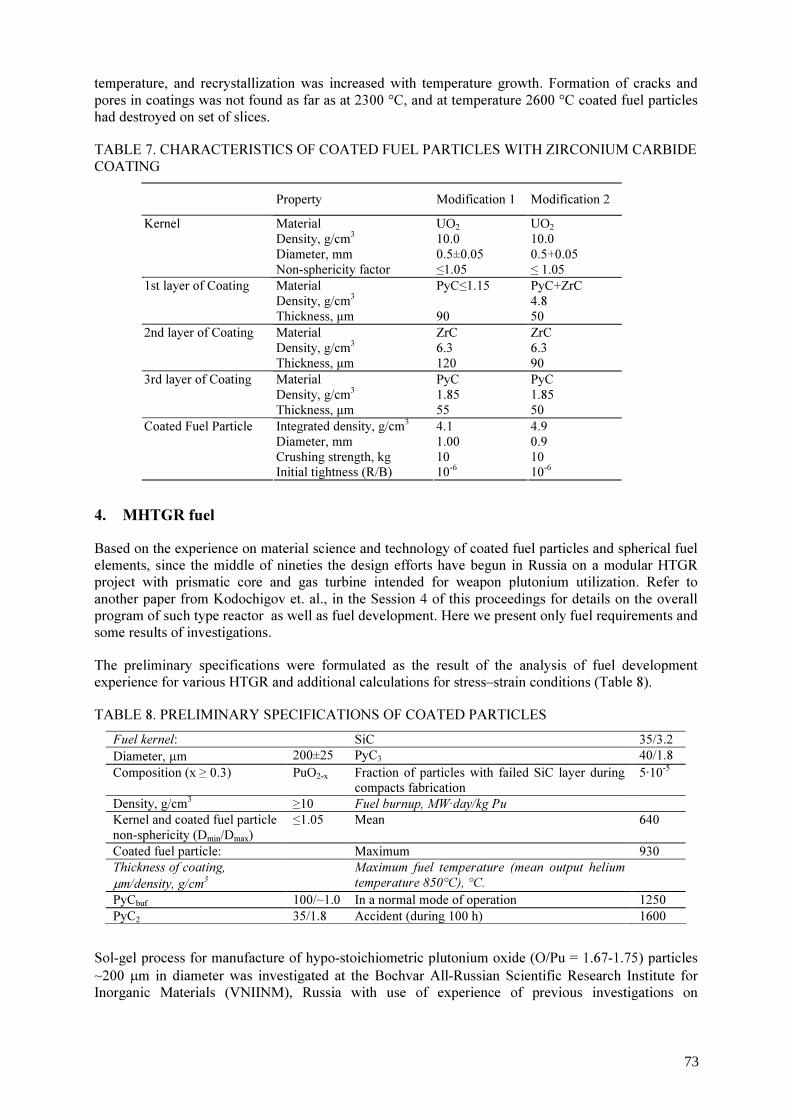
temperature, and recrystallization was increased with temperature growth. Formation of cracks and pores in coatings was not found as far as at 2300 °C, and at temperature 2600 °C coated fuel particles had destroyed on set of slices. TABLE 7. CHARACTERISTICS OF COATED FUEL PARTICLES WITH ZIRCONIUM CARBIDE COATING
Property Modification 1 Modification 2 Material UО2 UО2 Density, g/cm3 10.0 10.0 Diameter, mm 0.5±0.05 0.5+0.05
Kernel
Non-sphericity factor ≤1.05 ≤ 1.05 Material Density, g/cm3
PyC≤1.15 PyC+ZrC 4.8
1st layer of Coating Thickness, µm 90 50 Material Density, g/cm3
ZrC 6.3
ZrC 6.3
2nd layer of Coating Thickness, µm 120 90 Material Density, g/cm3
PyC 1.85
PyC 1.85
3rd layer of Coating Thickness, µm 55 50 Integrated density, g/cm3 4.1 4.9 Diameter, mm 1.00 0.9 Crushing strength, kg 10 10
Coated Fuel Particle
Initial tightness (R/B) 10-6 10-6 4. MHTGR fuel Based on the experience on material science and technology of coated fuel particles and spherical fuel elements, since the middle of nineties the design efforts have begun in Russia on a modular HTGR project with prismatic core and gas turbine intended for weapon plutonium utilization. Refer to another paper from Kodochigov et. al., in the Session 4 of this proceedings for details on the overall program of such type reactor as well as fuel development. Here we present only fuel requirements and some results of investigations. The preliminary specifications were formulated as the result of the analysis of fuel development experience for various HTGR and additional calculations for stress–strain conditions (Table 8). TABLE 8. PRELIMINARY SPECIFICATIONS OF COATED PARTICLES
Fuel kernel: SiC 35/3.2 Diameter, µm 200±25 РуС3 40/1.8 Composition (x ≥ 0.3) PuO2-x Fraction of particles with failed SiC layer during
compacts fabrication 5·10-5
Density, g/cm3 ≥10 Fuel burnup, MW·day/kg Pu Kernel and coated fuel particle non-sphericity (Dmin/Dmax)
≤1.05 Mean 640
Coated fuel particle: Maximum 930 Thickness of coating, µm/density, g/cm3
Maximum fuel temperature (mean output helium temperature 850°C), °C.
РуСbuf 100/~1.0 In a normal mode of operation 1250 РуС2 35/1.8 Accident (during 100 h) 1600
Sol-gel process for manufacture of hypo-stoichiometric plutonium oxide (О/Pu = 1.67-1.75) particles ~200 µm in diameter was investigated at the Bochvar All-Russian Scientific Research Institute for Inorganic Materials (VNIINM), Russia with use of experience of previous investigations on
73

preparation of uranium dioxide kernels. PuО2-x kernels with the following characteristics were prepared in laboratory experiments: diameter 200±25 micron, density 10.2-10.4 g/cm3. Coating of simulators (particles from natural enrichment uranium dioxide) is under investigation on a fluidized-bed laboratory installation of SIA Lutch. Because of essential difference of particles diameter from the previous Russian designs, fluidized-bed apparatus design required improvement (Fig. 2).
FIG. 2. General view of fluidized-bed apparatus.
The preliminary coating flow chart was proposed and TRISO-type coated fuel particles with kernels 200 microns in diameter were prepared. Fig. 3 and 4 presents some characteristics of such coated fuel particles.
FIG. 3. Distribution of coating thickness: a) РуСbuf, ~0.95 g/cm3; b) РуС1, 1.9 g/cm3; c) SiC, 3.19 g/cm3; d) РуС2, 1.83 g/cm3 FIG. 4. Microstructure of coated fuel
particle, x100.
74

5. Conclusion Investigations are now in progress in the following directions:
� Optimization of the flow chart and conditions of coating taking into consideration features of the small sizes of fuel particles and loading;
� Study of structural features and presence of defects in SiC layer. Besides, the work on designing is on the final stage and the equipment manufacture for fuel kernels, coatings and compacts preparation in laboratory conditions was started. This equipment will be mounted in the bench scale facility (BSF) at VNIINM and it will be put into operation in the current year first with uranium fuel with the subsequent transition to plutonium fuel.
75
Present status of HTTR project in Japan
K. Sawa, S. Fujikawa, M. Ogawa Oarai Research Establishment, Japan Atomic Energy Agency Niibori, Narit-cho, Oarai-machi, Higashiibaraki-gun, Ibaraki, Japan
Abstract. The high temperature engineering test reactor (HTTR) achieved the reactor outlet coolant temperature of 950 oC on April 19, 2004. Research and developments of the high temperature gas-cooled reactor (HTGR) that has merits of supplying high temperature heat, inherent safety features, high thermal efficiency, high burnup of fuel, and so on are particularly important for diversification of energy supply in the future. In addition, progress of innovative basic research is expected by utilizing capacity of the HTGR for irradiation of large-scale test specimens under high temperature conditions. In this paper, we describe present status of operation and tests of the HTTR, and research on nuclear heat application.
1. Introduction The high temperature gas-cooled reactor (HTGR) has the capability of producing high temperature heat of about 1000 °C that can expand the nuclear energy utilization to various fields. Also, it has the inherent safety features that can simplify safety systems and eventually enhance economical advantages over the other systems. History and future plan of the high temperature engineering test reactor (HTTR) project is shown in Fig. 1. Japan Atomic Energy Research Institute (JAERI; currently called as Japan Atomic Energy Agency JAEA) has carried out the research and development on the HTGR and high temperature heat applications since 1960s. Based on the long-term program for research, development and utilization of nuclear energy revised by the Atomic Energy Commission of Japan in 1987, the construction of the HTTR was determined and initiated at the Oarai research establishment of JAERI in 1991. The major specifications of the HTTR are summarized in Fig. 2. The HTTR attained the first criticality on November 10, 1998, and achieved the full power of 30 MW with the reactor outlet coolant temperature of 850 °C and 950 °C on December 7, 2001 and April 19, 2004, respectively. After series of safety demonstration tests, it will be used for the heat source of a hydrogen production system by 2015. The purpose of the HTTR project is to establish HTGR and nuclear heat utilization technologies and to carry out basic research on high temperature irradiation.
76

FIG. 1. History and future plan of the HTTR project.
FIG. 2. Major specifications of the HTTR.
77

JAERI has stressed the importance of research and development on the hydrogen production considering significance of hydrogen as an energy carrier for energy security and prevention of global climate change. To achieve early deployment of hydrogen society benign for the human health and environment, JAERI is acting as the prominent organization for the HTGR and hydrogen production technologies, and the HTTR is used as a centre facility for the development of these technologies in the world. The HTTR project enables the HTGR and related nuclear heat application technologies to be deployed after 2015. As a result, the nuclear heat will be applicable to various fields such as chemical industries, which currently emit large amount of carbon dioxide. The hydrogen production using the nuclear heat will completely cut the emission of carbon dioxide and make it possible to realize an ultimate clean hydrogen society. The system for generating electricity with high thermal efficiency of about 46% is expected to be safe and economically competitive system in 2010s. The HTGR and related heat application technologies can contribute to the environmental preservation by reducing dependence on fossil fuels and effectively using the nuclear energy. 2. R&D programs for HTTR The major R&D programs carried out for the HTTR construction are shown in Fig. 3.
2.1. Fuel Fabrication technology of high quality coated fuel particles with low failure fraction and high irradiation resistance was developed. Irradiation tests on the fuel performance under normal operating conditions were conducted using the OGL-1 (Oarai gas loop No. 1), the gas-swept capsules and the closed capsules at the JMTR (Japan Materials Testing Reactor), and the closed capsules at the JRR-2 (Japan research reactor-2). Fuel behaviour under accident conditions was also investigated in out-of-pile ramped and isothermal heating tests on irradiated coated fuel particles.
FIG. 3. The major R&D facilities for the HTTR construction.
78

2.2. Graphite High-grade graphite IG-110 with high strength, corrosion and irradiation resistance was developed and graphite structural design guideline was established. The studies on mechanical properties and non-destructive test of the nuclear grade graphite were performed to support the design and acceptance inspection for the HTTR core and core support components. 2.3. Metallic materials Heat and corrosion resistant superalloy Hastelloy XR was developed, which can be used at temperatures as high as 950 °C at normal operation and 1000 °C in accidents, and high temperature structural design guideline for high temperature metallic components was established. Comprehensive qualification tests such as creep, fatigue, corrosion, etc. on Hastelloy XR were carried out to accumulate the test data for structural design and safety evaluation. R&D on a long-term target alloy, Ni-Cr-W superalloy, was carried out for application at service temperatures around 1000 °C. 2.4. Reactor physics Reactor physics experiments were conducted using a very high temperature reactor critical assembly (VHTRC). Seven different cores having radial and axial reflectors were assembled at the VHTRC to study the detailed neutronic characteristics of the HTTR core. The VHTRC-1 and –2 cores were loaded mainly with 4wt%-enriched fuel and the VHTRC-3 core was loaded mainly with 6wt%-enriched fuel. These three cores had an axially uniform loading pattern. On the other hand VHTRC-4, -5, -6 and –7 cores were loaded with 2. 4 and 6wt%-enriched fuel rods in axially zoning patterns. 2.5. Components and structures at high temperature The helium engineering demonstration loop (HENDEL) was constructed for performing full-scale demonstration tests on the core internals and high temperature components for the HTTR. In the fuel stack test section (T1) of the HENDEL, thermal and hydraulic performances of helium gas flowing through a fuel rod channel and a fuel stack were investigated for the HTTR core thermal design. In addition, functioning reliability of a control rod drive mechanism and a control rod assembly was confirmed using a mock-up model. On the other hand, demonstration tests were conducted to verify thermal and hydraulic characteristics and structural integrity related to the core bottom structure using a full-scale test facility named as the in-core structure test section (T2). For example, sealing performance tests revealed that leakage of low-temperature helium gas through gaps between the permanent reflector blocks to the core is at very low level compared with the HTTR design value and no change of the leakage flow rate were observed after a long term operation. 3. HTTR project 3.1. HTGR reactor technology Based on the HTTR operational data, the HTGR reactor performance has been evaluated and analytical computer codes are verified or modified for predicting realistic reactor performance under steady state and operational transient conditions. The evaluation is focused on: (a) Core physics in relation with thermal response and control system, (b) Thermal analysis for fuel, reactor internals and high temperature components, (c) Fuel performance on fission product release and degradation of the coating layers to contain the fission products, (d) Structural integrity of reactor internals and high temperature components, (e) Decay heat and residual heat removal characteristics, and so forth. The fruits from the HTTR operational data and their evaluation are expected to be utilized for the commercial HTGR designs underway in South Africa, Russia, USA, etc. as well as for the design of the future Japanese advanced HTGR.
79

R&D on reactor technology is aiming at construction of a commercial HTGR power plant, such as gas turbine high temperature reactor 300 (GTHTR300) by industrial circles in the 2010s. On the basis of the reactor technology in the GTHTR300 that would attain competitive economy, high safety and sustainability, a commercial H2-HTGR would be constructed by industry circles in the 2030’s. For this purpose, R&D on hydrogen production technology and system integration is being carried out in parallel with the R&D on reactor technology in the HTTR program. 3.2. Safety demonstration test It is well known that the HTGR has inherent safety features characterized by no risk of reactor core meltdown even if the forced core cooling systems does not function with failure of reactor shutdown system. It is one of the best ways for the wide public acceptance to demonstrate such inherent safety of the HTGR using an actual HTGR. It is, therefore, planned in the HTTR to conduct a safety demonstration test. The safety demonstration test is divided into two phases. The first phase test, which simulates the anticipated operational occurrences without a reactor scram, includes primary coolant flow reduction test and a control rod withdrawal test at power operation. These tests are being conducted from 2002 to 2005. On the contrary, the second phase test simulating the severe accident conditions will be conducted after completion of the first phase tests. The second phase tests include the loss of cooling, all blackout, depressurization, reactivity insertion and etc. An example of the test result is shown in Fig. 4.
3.3. System integration of HTTR hydrogen production system HTGR and a hydrogen production system are connected by the helium loop. Chemical reactor in the hydrogen production system can cause the temperature fluctuation of helium gas by the fluctuation of the reaction during start-up and shut down as well as malfunction or accident of the process gas line. The reactor cannot continue the operation if the temperature fluctuation exceed the acceptable limit. Hydrogen production system is not classified for nuclear system from viewpoint of economy.
FIG. 4. An example of the safety demonstration test.
80

Redundant system to reduce the possibility of malfunction occurrence is not reasonable way. Thus, control technology between HTGR and hydrogen production system has to be developed to mitigate the fluctuation of helium gas temperature returning from hydrogen production system to the reactor and to prevent the reactor shut down. JAERI has planned to connect a hydrogen production system to the HTTR to establish the system integration technology. Figure 5 shows the schematic drawing of the HTTR hydrogen production system [1]. Prior to the connection, the pilot plant test of hydrogen production system has been carried out [2]. The steam-methane reforming process is selected as a coupling process to HTTR because it is mature chemical process and control technology for this process has been well developed.
Safety related technologies such as tritium permeation from core into produced hydrogen and explosion near the nuclear plant are significant issues as well as the control technology. It is well known that hydrogen isotopes can easily permeate through solid metals in high-temperature components such as heat exchanger tubes of intermediate heat exchanger and chemical reactor. Hydrogen produced in this system will be used as fuel of fuel cell vehicles and tritium water will be released to environment. Therefore tritium contamination in the hydrogen should be reduced to be sufficiently low. A hydrogen and deuterium permeation test was carried out to evaluate the tritium permeation rate through heat exchanger tubes. Explosion of hydrogen or other combustibles should be taken into account in the design of the HTGR hydrogen production system because HTGR and the hydrogen production system will be constructed side by side. In an existing nuclear power plant a large amount of combustibles is not stored and treated so that a large scale of fire and explosion is not considered in the current safety evaluation. Safety design concept for the H2-HTGR should universally be based on the defense in depth concept to achieve a high degree of safety. This consists of preventing occurrence of accident, preventing enlargement of accident and mitigating consequence of accident in adequate balance. Some reasonable measures should be employed to prevent the leak of combustibles, to detect the leakage and to mitigate the blast overpressure on reactor building by explosion.
FIG. 5. HTTR hydrogen production system.
81

3.4. Thermochemical water splitting IS process Thermal decomposition of water requires very high temperature heat more than 4000 °C. Electrolysis can also decompose water at atmospheric temperature but it requires much electric power. Thus, many other methods to separate hydrogen form water have been developed. Thermochemical methods were proposed to decompose water by heat of around 900 °C supplied from a HTGR. JAERI has been conducting R&D on the iodine-sulfur (IS) process since 1986 [3]. The IS process is composed of three chemical reactions as shown in Fig. 6. The raw material of water reacts with sulfur dioxide (SO2) and iodine to produce hydrogen iodine (HI) and sulfur acid (H2SO4) in the Bunsen reaction. HI is thermally decomposed to produce hydrogen. Thermal decomposition of H2SO4 to produce oxygen has favourable characteristics to use high temperature helium gas around 900 °C supplied from an HTGR. The R&D on the IS process consists of three research fields; experimental verification of continuous hydrogen production, process improvement and corrosion resistant material development.
A closed loop test had conducted using a glass-made test apparatus to identify the fundamental reactions and separations of the IS process. The continuous and stable hydrogen production of 0.001Nm3/h with stoichiometric ratio of water decomposition reaction was carried out for 48 hours. Based on this experiment, a scaled-up glass-made apparatus with 0.05Nm3/h of hydrogen production rate was set up. Newly devised pumps and sensors for monitoring the process parameters such as the flow rate and the liquid level are equipped. And residual HI and H2SO4 are recycled within the HI decomposition process and the H2SO4 decomposition process respectively. Process solution of high iodine concentration can be handled at elevated temperature with better separation rate of HI and H2SO4 expected. After operation tests of each reaction, combined operation test has been performed since 2003. Continuous hydrogen production operation with 0.032Nm3/h for 20 hours was attained in December 2003 as shown in Fig. 7. Process improvement has been pursed on the HI decomposition process, where HI is separated from HIx solution supplied from the Bunsen reaction and decomposed to produce hydrogen. Simple way to realize the chemical change is distillation of HIx solution and thermal decomposition of gaseous HI. However, the presence of azeotropic composition in HI-H2O solution requires much thermal energy to distil it. JAERI was tried to solve this problem and proposed an application of membrane techniques.
FIG. 6. The diagram of IS process.
82
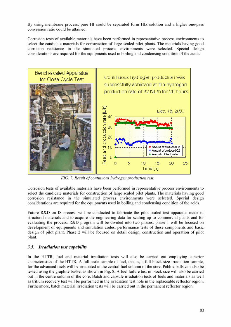
By using membrane process, pure HI could be separated form HIx solution and a higher one-pass conversion ratio could be attained. Corrosion tests of available materials have been performed in representative process environments to select the candidate materials for construction of large scaled pilot plants. The materials having good corrosion resistance in the simulated process environments were selected. Special design considerations are required for the equipments used in boiling and condensing condition of the acids.
Corrosion tests of available materials have been performed in representative process environments to select the candidate materials for construction of large scaled pilot plants. The materials having good corrosion resistance in the simulated process environments were selected. Special design considerations are required for the equipments used in boiling and condensing condition of the acids. Future R&D on IS process will be conducted to fabricate the pilot scaled test apparatus made of structural materials and to acquire the engineering data for scaling up to commercial plants and for evaluating the process. R&D program will be divided into two phases; phase 1 will be focused on development of equipments and simulation codes, performance tests of these components and basic design of pilot plant. Phase 2 will be focused on detail design, construction and operation of pilot plant. 3.5. Irradiation test capability In the HTTR, fuel and material irradiation tests will also be carried out employing superior characteristics of the HTTR. A full-scale sample of fuel, that is, a full block size irradiation sample, for the advanced fuels will be irradiated in the central fuel column of the core. Pebble balls can also be tested using the graphite basket as shown in Fig. 8. A fuel failure test in block size will also be carried out in the centre column of the core. Batch and capsule irradiation tests of fuels and materials as well as tritium recovery test will be performed in the irradiation test hole in the replaceable reflector region. Furthermore, batch material irradiation tests will be carried out in the permanent reflector region.
FIG. 7. Result of continuous hydrogen production test.
83
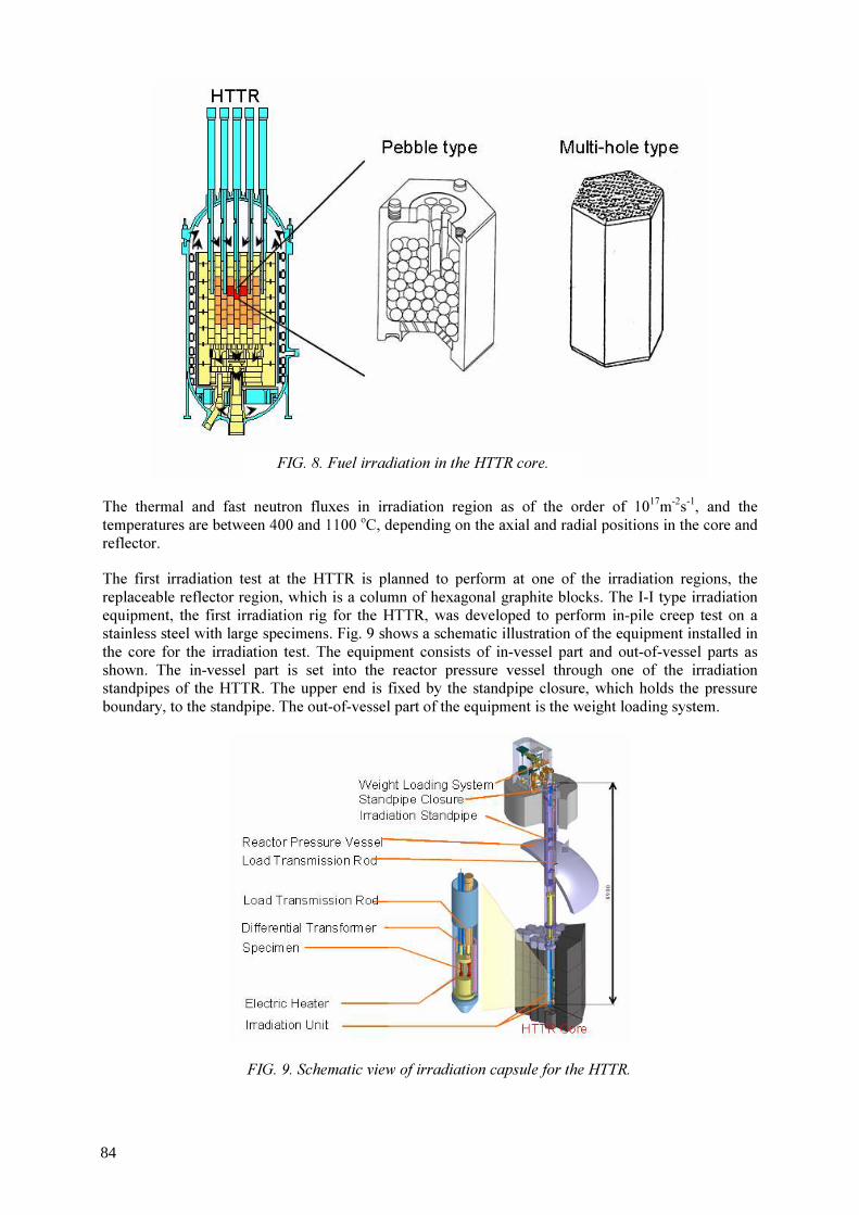
The thermal and fast neutron fluxes in irradiation region as of the order of 1017m-2s-1, and the temperatures are between 400 and 1100 oC, depending on the axial and radial positions in the core and reflector. The first irradiation test at the HTTR is planned to perform at one of the irradiation regions, the replaceable reflector region, which is a column of hexagonal graphite blocks. The I-I type irradiation equipment, the first irradiation rig for the HTTR, was developed to perform in-pile creep test on a stainless steel with large specimens. Fig. 9 shows a schematic illustration of the equipment installed in the core for the irradiation test. The equipment consists of in-vessel part and out-of-vessel parts as shown. The in-vessel part is set into the reactor pressure vessel through one of the irradiation standpipes of the HTTR. The upper end is fixed by the standpipe closure, which holds the pressure boundary, to the standpipe. The out-of-vessel part of the equipment is the weight loading system.
FIG. 8. Fuel irradiation in the HTTR core.
FIG. 9. Schematic view of irradiation capsule for the HTTR.
84

REFERENCES
[1] NISHIHARA, T., et. al., 2003, Development of control technology for the HTGR hydrogen production system, Proc. of International Conference on Future Nuclear Systems (Global -2003), Nov., 10-13, 2003, New Orleans,LA, Amercian Nuclear Soc., USA (2003) pp320-324.
[2] OHASHI, H., et al., Performance test results of mock-up test facility of HTTR hydrogen production system, Proc. Eleventh International Conference On Nuclear Engineering "Nuclear Energy - Dawn of a New Era" (ICONE-11), 20-23 April, 2003, Tokyo, Japan, Japan Society of Mechanical Engineers (JSME) and American Society of Mechanical Engineers (ASME), ICONE11-36059 (2003). http://www.jsme.or.jp/pes/icone11/index.html
[3] ATOMIC ENERGY COMMISSION OF JAPAN (AECJ), Long-term Program for Research, Development and Utilization of Nuclear Energy (2000).
85
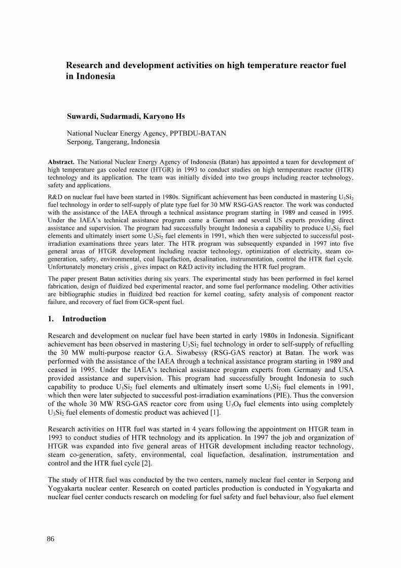
Research and development activities on high temperature reactor fuel in Indonesia
Suwardi, Sudarmadi, Karyono Hs National Nuclear Energy Agency, PPTBDU-BATAN Serpong, Tangerang, Indonesia
Abstract. The National Nuclear Energy Agency of Indonesia (Batan) has appointed a team for development of high temperature gas cooled reactor (HTGR) in 1993 to conduct studies on high termperature reactor (HTR) technology and its application. The team was initially divided into two groups including reactor technology, safety and applications. R&D on nuclear fuel have been started in 1980s. Significant achievement has been conducted in mastering U3Si2 fuel technology in order to self-supply of plate type fuel for 30 MW RSG-GAS reactor. The work was conducted with the assistance of the IAEA through a technical assistance program starting in 1989 and ceased in 1995. Under the IAEA’s technical assistance program came a German and several US experts providing direct assistance and supervision. The program had successfully brought Indonesia a capability to produce U3Si2 fuel elements and ultimately insert some U3Si2 fuel elements in 1991, which then were subjected to successful post-irradiation examinations three years later. The HTR program was subsequently expanded in 1997 into five general areas of HTGR development including reactor technology, optimization of electricity, steam co-generation, safety, environmental, coal liquefaction, desalination, instrumentation, control the HTR fuel cycle. Unfortunately monetary crisis , gives impact on R&D activity including the HTR fuel program. The paper present Batan activities during six years. The experimental study has been performed in fuel kernel fabrication, design of fluidized bed experimental reactor, and some fuel performance modeling. Other activities are bibliographic studies in fluidized bed reaction for kernel coating, safety analysis of component reactor failure, and recovery of fuel from GCR-spent fuel.
1. Introduction Research and development on nuclear fuel have been started in early 1980s in Indonesia. Significant achievement has been observed in mastering U3Si2 fuel technology in order to self-supply of refuelling the 30 MW multi-purpose reactor G.A. Siwabessy (RSG-GAS reactor) at Batan. The work was performed with the assistance of the IAEA through a technical assistance program starting in 1989 and ceased in 1995. Under the IAEA’s technical assistance program experts from Germany and USA provided assistance and supervision. This program had successfully brought Indonesia to such capability to produce U3Si2 fuel elements and ultimately insert some U3Si2 fuel elements in 1991, which then were later subjected to successful post-irradiation examinations (PIE). Thus the conversion of the whole 30 MW RSG-GAS reactor core from using U3O8 fuel elements into using completely U3Si2 fuel elements of domestic product was achieved [1]. Research activities on HTR fuel was started in 4 years following the appointment on HTGR team in 1993 to conduct studies of HTR technology and its application. In 1997 the job and organization of HTGR was expanded into five general areas of HTGR development including reactor technology, steam co-generation, safety, environmental, coal liquefaction, desalination, instrumentation and control and the HTR fuel cycle [2]. The study of HTR fuel was conducted by the two centers, namely nuclear fuel center in Serpong and Yogyakarta nuclear center. Research on coated particles production is conducted in Yogyakarta and nuclear fuel center conducts research on modeling for fuel safety and fuel behaviour, also fuel element
86

fabrication, experimental study for kernel fabrication, design and installation of laboratory scale fluidized bed reactor for kernel coating. Research activities have been conducted that covers these areas: kernel fabrication, kernel coating, recovery of fuel from GCR-spent fuel, coating particles, modeling of particle safety and behaviour, mechanical performance of spherical fuel of HTR. Modeling fission product release under the loss of coolant accident (LOCA) was also carried out. 2. Research and development activities 2.1. Fuel kernel production by Sol-gel and other processes 2.1.1 Comparative study on preparation of UO2 micro-spheres using proposed method and KEMA process Based on some methods for preparation of UO2 micro-spheres that have been applied in the laboratory and in the pilot scale, an alternative of more simple process flow sheet was prepared. In order to examine some steps of processes in the flow sheet, some experimental works were carried out. The optimum conditions of the processes have been obtained. The experimental optimum conditions were compared to the result of KEMA processes (developed by Dutch Royal Institute for Testing Electrical Material Research Arnhem; KEMA). The experimental results show that the proposed process route can be applied to prepare UO2 micro-spheres with sufficient confidence. The optimum experiment results were such that uranyl nitrate used was 200-250 g/l, with 80 g/L addition. This chemical solution then was gelled using column containing U. Subsequently the, formed gel was washed with dilute ammonia (5%), dried at 275 °C and calcinated at 800 °C. Micro-spheres then were reduced using H2 gas at 900 °C [3]. 2.1.2. Kernel particles and coating process for HTR fuel Bibliographic study of kernel fuel particles and coating process for HTR fuel has been made. Production of pyrocarbon and SiC coatings were done by thermal decomposition of hydrocarbon molecules and methyltrichlorosilane, respectively. Besides using methyltrichlorosilane, the SiC coating can be produced using esther silicide acid. For producing SiC coating from esther silicide acid, high temperature vacuum furnace is used [4]. 2.1.3. The influence of uranium content and PVA/U ratio on physical properties of PVA-U gel and its oxide Fifty milliliters of uranyl nitrate solution containing 5 g U was neutralized using 1M NH4OH. The solution was converted into polyvinyl alcohol (PVA)-U sol by adding 9.18% PVA while mixing and heating at 80 °C for 20 minutes. In order to form spherical gel, the sol solution was dropped into a 5 M NH4OH solution at room temperature. The gels are formed in spherical shape. The gels were filtered, washed and heated at 120 °C. After that, the gels were calcined at 800 °C for 4 hours to form U3O8 particles. Using the above method, the influence of uranium content in the range 150 - 400 g/l and the influence of PVA/U ratio in the range 6.5 - 12.5% in 100 g U/l were studied. Physical properties of the gel and its oxide in the form of density using pycnometer, surface area using surface areameter with N2 as absorbent and particles size/shape using a loop and optical microscope were measured. The experimental results indicates that both uranium content and PVA/U ratio affects the physical properties of the kernel. The best optimized result occurred at uranium content of 100 g/l and PVA/U 9.18%. The resulted gel had indicated solid content of 89.17%, density of 3.36 g/l and size of 124 µm. The resulted oxide U3O8 had density of 7,98 g U/l, surface area of specific of 0,449 m2/g and grain size of 810 µm [5]. 2.1.4. The influence of [NH4
+]/[NO3-] on the formation of sol and calcination temperature on
U3O8 gel by complexe agent polyvinyl alcohol
87

The research on the influence of [NH4+]/[NO3
-] percentage on tire-resulted sol and calcination temperature on the U3O8 gel. The variation of [NH4
+]/[NO3-] percentage, were 20, 30, 40, 50, 60 and
70%. The calcination was carried out at 200, 400, 600, 700 and 800 °C. The variation of calcination temperature in combination of parametric variation of [NH4
+]/[NO3-] was researched. The good U3O8
gel and optimum density of sol process was resulted at 60% [NH4+]/[NO3
-] and at fixed calcination temperature of 800 °C .The highest density resulted at the calcination temperature of 700 °C and the percentage parameter of 50%. The density was 7.8869 g/ml [6]. 2.1.5. The effect of washing and calcination on the properties of thorium-uranium gel and ThO2~U308 Precipitation of mixed Th(OH)4 and (NH4)2U2O7 was made by reacting mixed solution of Th(NO3)4 and UO2(NO3)2 with 8 M of NH4OH at pH 7 and temperature of 80 °C. This mixed solutions contained 2 mole Th/1 and the uranium content was 15% of Th. Th-U sol was prepared by dissolving the precipitate ion into 0,1 M of HNO3, stirred and heated at 80 °C. Its acidity was arranged at pH of 3.8. Fifty milliliter of PVA solution was added into hot sol and stirred for 20 minutes. In order to find Th-U gel in the spherica1 shape, this Th-U sol was dropped into 3 M of HNO3 at ambient temperature. The formed gel was micro-spheres in shape; they were filtered, washed and dried. The effect of washing time (5 - 30 minutes), calcination times (0,5 - 5 hours) and the calcination temperature (300 - 800 °C). The product quality was characterized from the gel and particle properties such as gel density, and particle size. The results showed that washing and calcination processes influenced the gel and thorium-uranium oxides density and particle size. The optimum conditions occurred at washing time of 15 minutes, calcination time of 3-4 hours and calcination temperature of 700 - 800 °C. After drying at 120 °C for 4 hours, gel density was 3,83 g/ml and its average size was 1615 um. Thus formed ThO2-U308 have an average density of 8.73 g/ml and average diameter of 997 um [7]. 2.1.6. Sintering investigation of UO2 gel The gel was prepared through two ways. The first gel was produced using PVA point of view as additive agent. The second gel was produced using hexamethylene tetraamine (HMTA) and urea as additive agent. From the preparation of gel, the PVA method is better than the urea-HMTA method, because cooling is not necessary for sol preparation and also heating is not necessary for gelation process. The percentage of intact sintered gel produced by the gel through PVA method is higher than one produced from HMTA method [8]. 2.1.7. The influence of oxidation on quality of UO3 kernels The influence of time and temperature at oxidation of Uranyl-4(ammonia)-2(polyvinyl alcohol) gel on surface area, pore radius, pore volume, porosity and diameter size of UO2 kernel. The spherical gel of uranyl-4(ammonia)-2(polyvinyl alcohol) containing 150 g-U/L were oxidized at 200 - 800 °C for 2 - 24 hours, formed UO2 kernel. The quality of UO2 kernel was measured by their physical properties i.e. the surface area and pore radius using surface area meter with N2 gas as absorbent. The pore volume and porosity using picno-meter with ‘aqua-bidest’ of water as a solvent, diameter size using an optical microscope. The experiment results showed that the time and temperature of oxidation of uranyl-4(ammonia)-2(polyvinyl alcohol) grain will influence the quality of UO2 rarely the surface area, pore radius, pore volume , and diameter size of UO2 kernel. The best results observed for conditions oxidation temperature 600 - 800 °C and oxidation times around 2-5 hours. The resulted quality of UO2 kernel was with surface area of 10.84 - 5.99 m2/g, pore volume of 10.35 x 10⁻² - 3.23x10⁻³ ml/g, pore radius was 21.05 - 24.62 A, diameter size around 1264 – 1456 um and porosity around 49.49 - 21.36 %vol. with cumulative analysis error 8.55 vol.% [9]. 2.1.8. SiC coating using CVD method Study of SiC coating on carbon coated particle using CVD method in fluidized reactor has been carried out. The objective is to determine the mass transfer coefficient in coating process. Carbon
88

feeds according to specified size were put into a crucible in the reactor. The equipment was arranged and was inspected from leaking. Heater was run and the reactor was flowed with inert gas until it reached the definite temperature, then the spent coatings were flowed. After the process was finished, the coating gas current was stopped, but the inert gas current was continued. After sufficient cooling of the reactor, the reactor was opened; product of process was taken out for analysis using microscope optic equipment. The studied variables were temperature in the range 70 – 1000 °C and rate of hydrogen gas in the range between 63 - 140 ml/minutes. The investigation found that mass transfer coefficient was not influenced by variation of temperature, but influenced with the gas rate [10]. 2.1.9. The influences of time and velocity of inert gas on the quality of graphite matrix on baking step The research on the synthesis of matrix graphite on the step of baking process was conducted, by focusing on the inffluence of time and velocity of the inert gas. The investigation on baking times ranging from 5 to 55 minutes and the velocity of inert gas marging from 0.30 l /minutes to 3.60 l/minutes, resulted in the product of different matrix. Optimizing the time of operation and the flow rate of argon gas indicated that the baking time for 30 minutes and the flow rate of argon gas of 2.60 l/ minute would give best matrix graphite which has a hardness value of 11 kg / mm2 and the ductility of 1800 Newton [11]. 2.2. Modeling for HTR fuel safety and behaviour 2.2.1. Model for strength evaluation of coating layers of fuel particle in restraint of internal gas pressure Coated fuel particles contained in graphite matrix are used in high temperature reactor. The main purpose of coating layer is to retain fission products within the fuel particles. Therefore, the safety and the performance of reactor operation depend on the mechanical integrity of the coating layers. A calculation model for strength evaluation of coating layer to restrain internal gas pressure is presented in this paper. In the model, coating layer is assumed as thick walled – spherical pressure vessel. And some parameters such based on internal pressure are used to evaluate the integrity of coating layer. Based on this model, strength evaluation of coating layers of fuel particle for high temperature test reactor (Japan) was carried out and the results show that all coating layers of fuel particle are able to restrain the build up of internal gas pressure [12]. 2.2.2. Failure probability prediction of TRISO coated fuel particle TRISO coated fuel particles contained in graphite matrix are used as fuel in modern high temperature reactor. The main purpose of coating layer is to retain fission products within the fuel particles and to minimize their release to primary reactor coolant below the acceptable level. Therefore, the safety and performance of reactor operation depend on the mechanical integrity of the coating layers. This part of paper presents a calculation model to predict a failure probability of coating layer due to internal gas pressure (fission gases and CO gas). In the model, calculation of failure probability is based on maximum stress acting on each coating layer caused by the internal gas pressure. To calculate the stress, the coated fuel particle is modelled as thick-walled spherical pressure vessel. Based on this model, calculation of failure probability of coated fuel particle for the first loading fuel of the Japanese high temperature test reactor (HTTR) was carried out [13]. 2.2.3. Reliability analysis of high temperaturer reactor This part of paper presents the results of reliability analysis of the TRISO coated fuel particles for the high temperature test reactor (HTTR), Japan. The reliability of fuel particle was evaluated based on the failure probability of each coating layer, and only the failure due to internal gas pressure and shrinkage of pyrolitic carbon (PyC) layer was considered The analysis results show that, no significant failure occurs up to about 45 MWd/kgU for the first core fuel particle and up to about 75 MW d/kgU for the reload core fuel particle. The fuel particle is predicted to fail completely at about 50 MWd/kgU
89
for the first core fuel particle and at about 85 MWd/kgU for the reload core fuel particle. This results show that the TRISO coated fuel particle for the HTTR to have high reliability. No failure occurs up to the maximum burnup design level, i.e. 33 MWd/kgU for the first core fuel particle and 60 MWd/kgU for the reload core fuel particle. The analysis results show also that the fuel particle reliability (coating layers) depends on the irradiation temperature. The failure occurs at lower burnup if the irradiation temperature increases [14]. 2.2.4. Stress evolution in spherical fuel element during irradiation in high temperature reactor The stress-strain induced by thermal and irradiation behaviour of nuclear fuel during in-core irradiation may be used as an important reference for evaluation of fuel safety and reliability. The paper presents the prediction of stress-strain evolution of spherical fuel during in-core irradiation in steady-state conditions both thermal and neutronics. The spherical fuel is cooled by cooling gas environment and under fast neutrons irradiation and thermal generation by nuclear fission that the axial distributions are considered as steady state. The fuel flows from the top to the bottom of reactor core. A mathematical solution is demonstrated and then followed by the computer implementation in Mathcad environment. A test run of the computer implementation has been carried out by using a dummy input data. The results are presented as tabulated and graphical data. More realistic input data and calculation has been cited that may be used for benchmarking the developed code for further development. At initial stage the dose rate increases rapidly and deteriorates the material strength and causes the stress to decrease. But then the dose rate gradually decreases and the total stress increases about 3 times of thermal stress at 9.0E+21 accumulation dose. This data may be used for benchmarking [15]. 2.2.5. Study on fission product releases from HTR fuel element Simulation study was carried out initially at JAERI, Japan on HTTR fuel element which was modelled using bulk mass transfer method. The results shows that an alteration on the fuel coating system due to the change of very high temperature, particularly on the loss of coolant accident, cause fission products release such as Kr-85, Cs-134 and Cs-137. In addition to the changes of temperature, corrosion on the coating material can also lead to the release of fission products [16]. 2.2.6. Study on advanced reactor fuel production of (U,Th)O2 Utilization of uranium-233 - thorium cycle insures long-term fuel supply, makes the nuclear energy production more flexible and enables the self-provision regime to be realized in future. Flow sheet of mixed oxide fuel production for advanced reactor of (U, Th)O2 is a combination of existing manufacturing equipment and quality assurance program from commercial LWR and HTR. The front-end of flow-sheet uses the sol-gel process. The external sol-gel process is chosen due to simple equipment with anticipation of re-fabrication of U-233 which contains a few hundred of ppm of U-232 and its gamma-emitting daughters, besides yielding smaller waste. The decision to choose the external sol-gel process encourages developing external gelation thorium (EGT). In order to get higher density and relatively low compaction pressures (i.e. for advanced LWR) adopted flow sheet EGT is developed to be ‘sol-gel micro-sphere pelletization’ (SGMP). Using the optimal parameters, SGMP become established flow sheet for producing mixed oxide fuel of (U, Th)O2 for advanced reactor [17]. 3. Summary Batan has started research activities on HTR in 1993. HTR technology and it’s potential application in Indonesia. The team was initially divided into two groups including reactor technology and safety and applications. The HTR program was subsequently expanded in 1997 into five general areas of HTGR development including reactor technology and optimization of electricity and steam co-generation, safety and environmental, coal liquefaction and desalination, instrumentation and control and the HTR fuel cycle.
90

At the time when Batan began to study HTR fuel, the technology has already been developed by a half of dozen industrial countries, with about 30 years experience in HTR development. During the first six years activities in HTR fuel, two groups of studies have been performed. First group studied the basic process fabrication of fuel kernel and kernel coating, meanwhile second group studied modeling for fuel safety and behaviour. Some laboratory experiments have been carried out to produce kernel of oxide fuel. The objective of the activities is to achieve a better understanding of the HTR fuel technology that has already been developed by some countries. By referring the key development to achieve a good coated fuel particles for high temperature reactor fuel element, that is: • High density oxide kernel; • Low density buffer layer derived from ethyne; • TRISO coating, i.e., the sequence pyrocarbon, silicon carbide, and pyrocarbon; • Low-temperature isotropic pyrocarbon derived from propane; • High-quality SiC of near theoretical density derived from methyltrichlorosilane. Batan has started some researches of the first step. Despite a little number of researcher, utilizing simple apparatus and limited budget to complete their knowledge and capability in preparing kernels for coated particles, more than ten topics of research have been published. Most of these studies are about UO2 kernel fabrication and dispersed study on preparation on particles coating; U recovery from coated particle fuel. In fuel modelling a number of studies have been conducted on coated particles fuel modelling, mechanical sphere coat and failure probability.
ACKNOWLEDGEMENTS
The authors would like to express their appreciation to the division of nuclear fuel cycle and waste technology of the IAEA for the support given to the author for attending the technical meeting.
REFERENCES
[1] ASMEDI SURIPTO, SIGIT, ABDUL MUTALIB, ADIWARDOYO SUPARDJO, “RERTR-Related Program In Indonesia”, Proceedings of the 25th International Meeting on Reduced Enrichment for Research and Test Reactors, RERTR, Chicago, USA, 5-10 October 2003, RERTR Department, 9700 South Cass Ave., Argonne, IL 60439-4814, USA, http://www.rertr.anl.gov/RERTR25/index.html
[2] HASTOWO, H., Proceeding of 5th Seminar on High Temperature Reactor Technology and Application, Yogyakarta, 22 November 2000, ISSN: 0854 –8803 (2000).
[3] SUKARSONO, WARDAYA, BANGUN WASITO, INDRA SURYAWAN, “Comparison Study On Preparation Of UO2 Microspheres Using Proposed Process And KEMA'S PROSESS”, Prosiding Pertemuan dan Presentasi I/miah P3TM-BATAN, Yogyakarta 14-15 July 1999, pp 191-197 Buku II Teknologi Proses, (1999) ISSN 0216-3128.
[4] KUSNANTO, et al., “Fabrication of UO2 kernels”, Proceeding of 3th Seminar on High Temperature Reactor Technology and Application, Yogyakarta, 1997, ISSN: 0854–8803 (1997).
[5] INDRA SURYAWAN, DAMUNIR DAN SETYO SULARDI, “The Influence Of [NH4
+]/[NO3-] Percentage On The Result Of Sol And Calcination Temperature On The
U3O8 GEL By Complexs Agent Poly Vinil Alcohol”, Pros.Pertemuan dan Presentasilimiah Penelltlan Dasar IImu Pengetahuan dan Teknologl Nukllr, 27 June 2002, P3TM-BATAN
91

Yogyakarta, (2002), ISSN 0216-3128. [6] DAMUNIR, BANGUN, W., INDRA SURYAWAN, ENDANG NAWANGSIH, “The
influence of uranium content and PVA/U ratio on physical properties of PVA-U gel and its oxide”, Prosiding Pertemuan dan Presentasi Ilmiah Penelitian Dasar Ilmu Pengetahuan dan Teknologi Nuklir, 25-26 July 2000 P3TM-BATAN Yogyakarta, (2000) ISSN 0216-3128, pp262-267.
[7] DAMUNIR, SUKARSONO, BANGUN WASITO, “The effect of washing and calcination on the properties of thorium-uranium gel and ThO-U308”, Prosiding Pertemuan dan Presentasi I/miah P3TM-BATAN, 14-15 July 1999, Yogyakarta (1999) pp 198-202 Buku II Teknologi Proses, ISSN 0216-3128.
[8] SUKARSONO, DWI HERU SUCAHYO, HIDAYATI, EVI HERTIVIANA, BAMBANG SUGENG, “Sintering of Kernel UO2 For High Temperature Reactor Fuel”, Pros.Pertemuan dan Presentasilimiah Penelltlan Dasar IImu Pengetahuan dan Teknologl Nukllr, 27 June 2002, P3TM-BATAN Yogyakarta, (2002) ISSN 0216-3128.
[9] DAMUNIR, SUKARSONO, INDRA SURYAWAN, “The influence of oxidation on quality of UO3 kernels”, Pros.Pertemuan dan Presentasilimiah Penelltlan Dasar IImu Pengetahuan dan Teknologl Nukllr, 27 June 2002, P3TM-BATAN Yogyakarta, (2002) ISSN 0216-3128, pp 267-274.
[10] DWIRETNANI SUDJOKO, IMAM DAHRONI, HIDAYATI, “SiC Coating Using CVD Methode”, Prosiding Pertemuan dan Presentasi Ilmiah P3TM-BATAN, 14 -15 July 1999, Yogyakarta (1999) pp 142-146 Buku II Teknologi Proses ISSN 0216-3128.
[11] IMAM DAHRONI, DWI HERWIDHI, KASILANI NS, “The Enfluences of Time and Velocity of Inert Gas on The Quality of The Processing Pruduct of Graphite Matrix on the Baking Step”, Prosiding Pertemuan dan Presentasi Ilmiah Penelitian Dasar Ilmu Pengetahuan dan Teknologi Nuklir, 25-26 July 2000 P3TM-BATAN Yogyakarta, (2000) ISSN 0216-3128, pp231-235.
[12] BAMBANG HERUTOMO DAN TRI YULIANTO, “Model Evaluasi Kemampuan Lapisan Pelindung pada Partikel Bahan Bakar dalam Menahan Tekanan Gas Internal” Presentasi Ilmiah Daur Bahan Bakar Nuklir V, 22 Feb., 2000, Jakarta.(2000).
[13] HERUTOMO, B., “Analisis Keandalan Bahan Bakar Reaktor Temperatur Tinggi”, Presentasi Ilmiah Daur Bahan Bakar Nuklir V, 22 Feb., 2000.,Jakarta (2000).
[14] HERUTOMO, B., “Reliability Analisys of High Temperature Reactor Fuels”, Proceeding of 5th Seminar on High Temperature Reactor Technology and Application, 22 November 2000Yogyakarta, ,.(2000) ISSN: 0854–8803.
[15] SUWARDI, “Mathematical analysis of stress in spherical nuclear fuel element during irradiation in high temperature reactor”, Proceeding of Scientific Forum on 2003 Fuel Cycle, Serpong Jakarta, (2003).
[16] WAHYUNI, “Fission Product Releases from HTR Fuel element”, Proceeding of 3th Seminar on High Temperature Reactor Technology and Application, Yogyakarta, (1997), ISSN: 0854–8803.
[17] BUSRON MASDUKI, DAMUNIR, PRISTI HARTATI, SUKARSONO, R., BANGUN WASITO, “Study of Advanced Reactor Mixed Oxide Fuel Production of (U,Th)O2”, Proceeding of 5th Seminar on High Temperature Reactor Technology and Application, 22 November 2000,Yogyakarta, .(2000). ISSN: 0854 –8803.
92
Coated particle fuels for high temperature reactors – Indian programme
V.N. Vaidya Fuel Chemistry Division, Bhabha Atomic Research Centre, BARC Trombay, Mumbai, India
Abstract. India is embarking upon a programme to develop ‘compact high temperature reactor’ (CHTR). The fuel for this reactors is proposed to be TRISO coated UO2, (Th,U)O2,UC2 and (Th,U)C2 microspheres. The TRISO coated fuel after mixing with graphite will be extruded in form of rods and will be encased in graphite tubes. Work on the preparation of fuel in the form of microspheres has been in progress in India for last two decades. Internal Gelation Process has been developed for the preparation of 100 to 800 micron microspheres of UO2, ThO2, (U,Pu)O2, (Th,U)O2, UC, (U,Ce)C, UN etc. Study of the chemical parameters, process conditions, heat treatment schemes have been completed. An R&D programme on the preparation of fuel pellets using Sol-Gel Microsphere Pelletisation Process (SGMP) has been successfully completed for UO2, (U-ThO)2, (U,Pu)O2,and ThO2, pellets of desired quality required for various industrial application. Technological development for the disposal/recycle of low level liquid is almost complete and flow sheet has been made for the same. Development of a flow sheet for the preparation of coated particle fuel is in progress. Initial work has been undertaken to study the conditions for CVD coatings of carbon on spherical particles and to evolve suitable reactor tube designs for obtaining smooth defect free coatings of desired densities and mechanical properties. It is also proposed to use ZrC coating in place of SiC. This programme is expected to commence in near future.
1. Introduction Coated particle fuels have gained importance again with the revival of high temperature reactors. India has three stage nuclear power programme [1]. In the first stage deployment of PHWRs is being undertaken. The second stage will use U-Pu fuel cycle for fast breeder reactors. Advanced heavy water reactor (AHWR) is being designed to use U-Th fuels. A programme for U-Th based coated particle fuel for compact high temperature reactor (CHTR) is being undertaken to deploy small size reactors as power sources in remote areas. Third stage of development of the nuclear power programme is based on Th-233U fuel cycle. The current version of the design is shown in Fig. 1. The design features consists of BeO blocks. Nineteen BeO blocks contain 19 fuel tubes which are centrally located. Each fuel tube also serves as a coolant channel. Other details given in Figure 1 are reflector blocks of BeO and graphite. The reactor is cooled by liquid lead-bismuth alloy and is housed inside two stainless steel shell reactor vessel and outer container. Other important design details of CHTR are given in Table 1. The reactor aims at producing heat (100 kWth) at high temperature (~1000 oC) which can be used as a power source or for demonstration of high temperature application such as hydrogen generation.
93
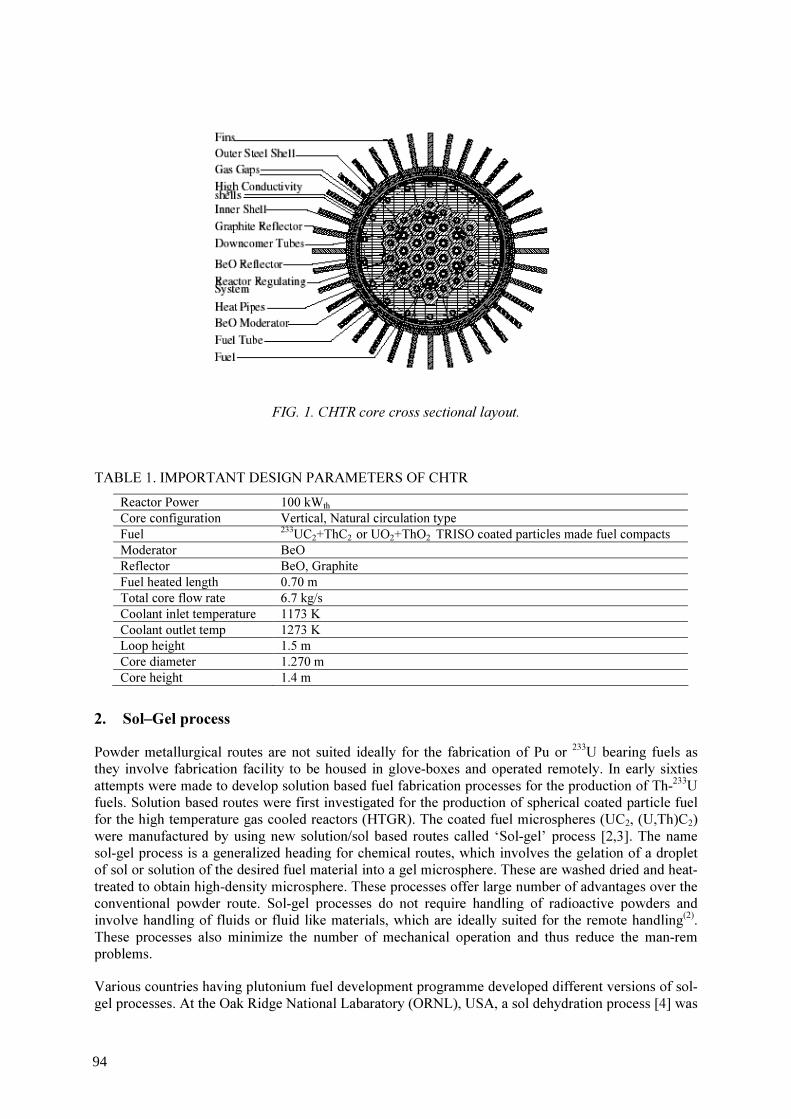
FIG. 1. CHTR core cross sectional layout.
TABLE 1. IMPORTANT DESIGN PARAMETERS OF CHTR Reactor Power 100 kWth Core configuration Vertical, Natural circulation type Fuel 233UC2+ThC2 or UO2+ThO2 TRISO coated particles made fuel compacts Moderator BeO Reflector BeO, Graphite Fuel heated length 0.70 m Total core flow rate 6.7 kg/s Coolant inlet temperature 1173 K Coolant outlet temp 1273 K Loop height 1.5 m Core diameter 1.270 m Core height 1.4 m
2. Sol–Gel process Powder metallurgical routes are not suited ideally for the fabrication of Pu or 233U bearing fuels as they involve fabrication facility to be housed in glove-boxes and operated remotely. In early sixties attempts were made to develop solution based fuel fabrication processes for the production of Th-233U fuels. Solution based routes were first investigated for the production of spherical coated particle fuel for the high temperature gas cooled reactors (HTGR). The coated fuel microspheres (UC2, (U,Th)C2) were manufactured by using new solution/sol based routes called ‘Sol-gel’ process [2,3]. The name sol-gel process is a generalized heading for chemical routes, which involves the gelation of a droplet of sol or solution of the desired fuel material into a gel microsphere. These are washed dried and heat-treated to obtain high-density microsphere. These processes offer large number of advantages over the conventional powder route. Sol-gel processes do not require handling of radioactive powders and involve handling of fluids or fluid like materials, which are ideally suited for the remote handling(2). These processes also minimize the number of mechanical operation and thus reduce the man-rem problems. Various countries having plutonium fuel development programme developed different versions of sol-gel processes. At the Oak Ridge National Labaratory (ORNL), USA, a sol dehydration process [4] was
94

developed. The process was demonstrated for the production of ThO2, UO2, (U,Pu)O2, and (U,Th)O2 microspheres. Another sol-based process was developed at CNEN in Italy called SNAM process. The process was a combination of external gelation of sol droplets in organic medium. At Forschungszentrum, Jülich, Germany (KFA) [5], a solution-based process called external gelation (KFA process) was developed for ThO2 and UO2 microspheres. At Harwell laboratory. UK, another version of external gelation called gel supported precipitation [3] was developed for UO2, (U,Pu)O2 microspheres. KEMA process also known as internal gelation process [6] was developed at KEMA laboratories in Netherlands and in many other countries [7] like USA, Germany, Russia, Czechoslovakia, Switzerland, and BARC India [8-10]. The sol-gel routes are designed to convert the output solution of reprocessing plant directly into consolidated gel particles, eliminating the powder handling and the associated hazards. Vibro- compaction of multiple sizes of high density microspheres in fuel pin cladding has been used to fabricate VIPAC type fuel pins. The history of irradiation behavior of power reactor fuels favour pellet fuel. Thus a hybrid process involving the sol-gel process in the front end of fuel fabrication merged with the pellet making process called SGMP was developed to get the best of the two processes [11-13]. 3. Internal gelation process Internal gelation process (IGP) is one of the well studied process in BARC for the preparation of gel microspheres of UO2, ThO2, (U,Pu)O2, (Th,U)O2, UC, UN [8-10] etc. The process uses the solutions of the nitrates of uranium, thorium and plutonium or their desired mixtures. The cooled (~0 oC) metal nitrate solutions are mixed with urea and hexa-methylenetetramine (HMTA) solution in cooled condition (~0 oC). The droplets of this mixture are contacted with hot oil (silicone oil ~90 oC) to make gel microspheres. These gel microspheres are washed first with CCl4 to remove the silicone oil and then with NH4OH solution to remove excess gelation agents HMTA and urea and ammonium nitrate. The washed particles are dried at 150 oC in air and then calcined up to 500 oC to remove residual organic matter and ammonium nitrate. The calcined microspheres are then reduced in N2+H2 mixture at 600 oC. The UO2 microspheres thus produced are sintered at 1200 oC for 3 hrs to produce >99% TD microspheres. The flow chart of the IGP is given in Fig. 2.
FIG. 2. Flow chart for IGP
95
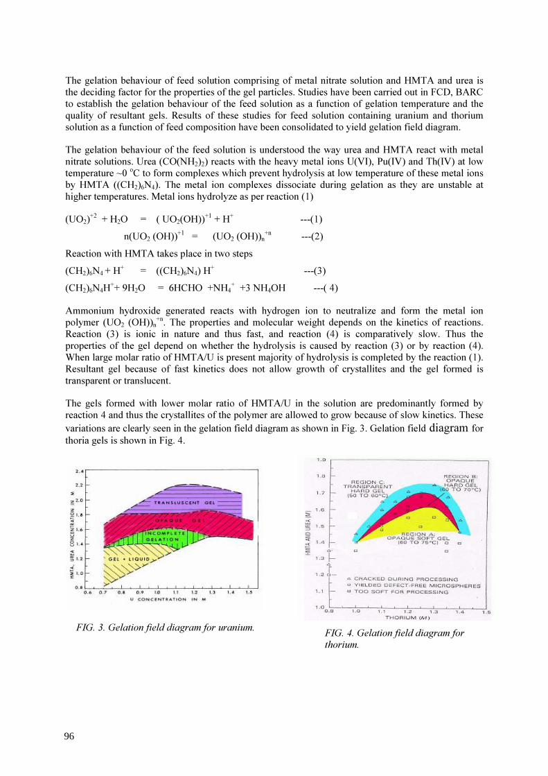
The gelation behaviour of feed solution comprising of metal nitrate solution and HMTA and urea is the deciding factor for the properties of the gel particles. Studies have been carried out in FCD, BARC to establish the gelation behaviour of the feed solution as a function of gelation temperature and the quality of resultant gels. Results of these studies for feed solution containing uranium and thorium solution as a function of feed composition have been consolidated to yield gelation field diagram. The gelation behaviour of the feed solution is understood the way urea and HMTA react with metal nitrate solutions. Urea (CO(NH2)2) reacts with the heavy metal ions U(VI), Pu(IV) and Th(IV) at low temperature ~0 oC to form complexes which prevent hydrolysis at low temperature of these metal ions by HMTA ((CH2)6N4). The metal ion complexes dissociate during gelation as they are unstable at higher temperatures. Metal ions hydrolyze as per reaction (1) (UO2)+2 + H2O = ( UO2(OH))+1 + H+ ---(1)
n(UO2 (OH))+1 = (UO2 (OH))n+n ---(2) Reaction with HMTA takes place in two steps (CH2)6N4 + H+ = ((CH2)6N4) H+ ---(3) (CH2)6N4H++ 9H2O = 6HCHO +NH4+ +3 NH4OH ---( 4) Ammonium hydroxide generated reacts with hydrogen ion to neutralize and form the metal ion polymer (UO2 (OH))n+n. The properties and molecular weight depends on the kinetics of reactions. Reaction (3) is ionic in nature and thus fast, and reaction (4) is comparatively slow. Thus the properties of the gel depend on whether the hydrolysis is caused by reaction (3) or by reaction (4). When large molar ratio of HMTA/U is present majority of hydrolysis is completed by the reaction (1). Resultant gel because of fast kinetics does not allow growth of crystallites and the gel formed is transparent or translucent. The gels formed with lower molar ratio of HMTA/U in the solution are predominantly formed by reaction 4 and thus the crystallites of the polymer are allowed to grow because of slow kinetics. These variations are clearly seen in the gelation field diagram as shown in Fig. 3. Gelation field diagram for thoria gels is shown in Fig. 4.
FIG. 3. Gelation field diagram for uranium.
elation field diagram for
FIG. 4. Gelation field diagram for thorium.
96

Feed compositions having uranium molarity from 1.0 to 1.4 M have been successfully used for the preparation of UO3 gel particles. These gel particles have been sintered to make >99%TD UO2 microspheres of 500 to 700 um dia. Fig. 5 shows sintered UO2 microspheres.
Regions involving lower molarity of uranium (0.7 to 0.9M) has been used for the preparation of UO2 of smaller diameters between 70 to 100 um dia. These microspheres are well suited for the vibro-compaction of fuel pins. The regions involving higher molarity of uranium >1.35 M lesser quantity of gelation agents HMTA and Urea are required per kg of uranium processed. Vibro-compaction of two or more sizes of high-density microspheres has been used as a method of fuel pin fabrication and is also called sphere-pac process. Using two sizes of microspheres fuel pins can be vibro-compacted to give 82-83% smear density in the fuel pin. Such fuel pins have been fabricated and irradiated in Fast and Thermal Reactors in many countries. In pile and post irradiation examination results of such experiments with mixed oxide, and carbide fuels have been very encouraging. 4. IGP for carbide microspheres The flow sheet of IGP is modified for preparation of mono carbide and di-carbide microspheres of uranium and thorium. Carbon powder is added in the feed solution by grinding the same in a solution of HMTA and urea prior to mixing of metal nitrate solutions. The feed broth containing carbon powder is then converted to gel microspheres by usual process. The washed gel particles are dried in air up to 100 oC and then heat treated in argon gas to remove residual moisture and organics at 300 oC. A vacuum furnace is used for the conversion of the heat treated gel particles to carbide microspheres. A detailed heat treatment (reaction sintering) scheme 300 to 1750 oC has been worked out to get UC, UC2, (U,Ce)C microspheres [14,15]. It is difficult to obtain desired C/M ratio in the feed broth as carbon powder tends to settle. This is achieved by proper choice of feed compositions having low metal ion concentration (~.7 to1.0 M) by the use of gelation field diagram. This helps in keeping the requirement of carbon in the feed solution low to achieve the C/M ratio. Good quality UC, UC2, (U,Ce)C carbide microspheres have been made using this process. Chemical reactions of the carbo-thermic reduction are following: 2UO3 + C = 2UO2 +CO2 (800 oC ) -(5) UO2 + 3C = UC + 2 CO (1200 - 1500 oC) -(6)
FIG. 5. Sintered UO2 microspheres of 700 um DIA.
97

Studies of kinetic parameters of carbothermic synthesis have been carried out(16). The sintering of the UC microspheres is carried out in high purity argon at 1750 oC. Coating of the microspheres Work has been initiated on the development of CVD coating of microspheres. To start the work a programme related to CVD coating of ZrC has been undertaken. The carrier Ar gas is loaded with equimolar mixture of CH4 and ZrCl4. This work is being carried out on alumina microspheres. Initial results are encouraging. A new assembly with graphite fluid bed reactor along with a gas manifold is under testing. 5. Conclusions India has interest in the development of coated particle fuel for it’s deployment in CHTRs and in VHTR s in future with view to developing economic source of hydrogen and as SMR for deployment in remote areas of the country. Sol-gel technology in India has already matured and work on coated particles is in progress.
ACKNOWLEDGEMENTS
The author is very much thankful to Shri R.K.Sinha, Shri I.V.Dulera of RED BARC. He also acknowledges gratefully the work of Dr. S.K.Mukherjee, Shri S.Suryanrayana, Shri R.V.Kamat, Shri J.Radhakrishna, Shri N.Kumar, Shri J.V.Dehadraya, Shri Ashok Kumar, Shri Rajesh Pai, Shri V.R.Ganatra, Shri T.V.Vittal Rao, Shri A.C.Deb, Shri Y.R.Bamankar, and Dr.K.T.Pillai of Fuel Chemistry Division, BARC. He is also thankful to Shri H.S.Kamat and Dr.V.Venugopal of BARC for encouraging me throughout this work.
REFERENCES [1] DEPARTMENT OF ATOMIC ENERGY, Nuclear Power for National Development: An
Indian Perspective, p 3, DAE Publication No. PA1/2001, July (2001). [2] LAHR, H.W.H., Fabrication, Properties, and Irradiation Behavior of U/Pu Particle Fuel for
Light Water Reactors, Nucl. Technol., 51 (1974) 232. [3] FOERTHMANN, R., BLASS, G., “Fabrication of uranium-plutonium oxide micro-spheres
by the hydrolysis process”, J. Nucl. Mat., 64 (1977), 275. [4] HAAS, P.A., BEGOWICH, J.M., RYON, A.D., VERUSKA, J.S., Chemical Flow-sheet
Conditions for Preparing Urania Spheres by Internal Gelation, USAEC Report ORNL/TM 6850 (1979).
[5] RINGEL, H., ZIMMER, E., Simplified Preparation of ThO2 and (Th,U)O2 Fuel Kernels, Trans. Am. Nucl. Soc., 27 (1977) 292-293.
[6] KANIJ, J.B.W., WOOTHOUT, A.J., VOTOCEK, D., “Sol Gel Process for Fuel Fabrication”, IAEA, Vienna, CONF-700502, p.253. (1970).
[7] INTERNATIONAL ATOMIC ENERGY AGENCY, Proceedings of a Panel on Sol-Gel Processes for Ceramic Nuclear Fuels, held in Vienna, 6-10 May 1968, IAEA, Vienna, STI/PUB/207, (1976).
[8] VAIDYA, V.N., MUKERJEE, S.K., JOSHI, J.K., KAMAT, R.V., SOOD, D.D., “A Study of Chemical Parameters of Internal Gelation Based Sol-Gel Process for Uranium Dioxide”, J.Nucl. Mater., 148 (1987) 324-331.
[9] VAIDYA, V.N., SOOD, D.D., “Experience in BARC on the preparation of Gel Microspheres of Uranium, Thorium and Plutonium fuels”, Material Science Forum vol 48-49 (1989).
[10] KUMAR, N., SHARMA, R.K., GANATRA, V.R., MUKERJEE, S.K., VAIDYA V.N.,
98

SOOD, D.D., “Studies of the preparation of thoria and thoria-urania microspheres using internal gelation process”, Nuclear Technology, 96 (1991) 169-177.
[11] SURYANARAYANA, S., KUMAR, N., BAMANKAR, Y.R., VAIDYA, V.N., SOOD, D.D., “Fabrication of UO2 pellets by gel pelletisation technique without addition of carbon as pore former”, J. Nucl. Mater., 230 (1996) 140-147.
[12] GANGULY, C., BASAK, U., VAIDYA, V.N., SOOD, D.D., ROY, P.R., “Sol-Gel Microsphere Pelletisation of UO2 and UO2-PuO2 Pellets of PHWR Specifications Using Internal Gelation Process”, Proc. of Second International Conference on CANDU Fuel, Canadian Nuclear Society, CNS, Ontario (Oct 1989) 108-124, http://www.cns-snc.ca/CNS_Conferences/Search/1989-4.htm
[13] PAI, R.V., MUKERJEE, S.K., VAIDYA, V.N., “Fabrication of (Th-U)O2 pellets containing 3% uranium by gel pelletisation technique”, J. Nucl. Mater., 325, (2004) 159-168.
[14] MUKERJEE, S.K., DEHADRAYA, J.V., VAIDYA, V.N., SOOD, D.D., “Kinetic study of the carbothermic synthesis of uranium monocarbide microspheres”, J. Nucl Mater., 172 (1990) 37-46.
[15] MUKERJEE, S.K., DEHADRAYA, J.V., VAIDYA, V.N., SOOD, D.D., “Kinetics and mechanism of UO2 +C reaction for UC/UC2 preparation”, J. Nucl. Mater., 210 (1994) 107.
99
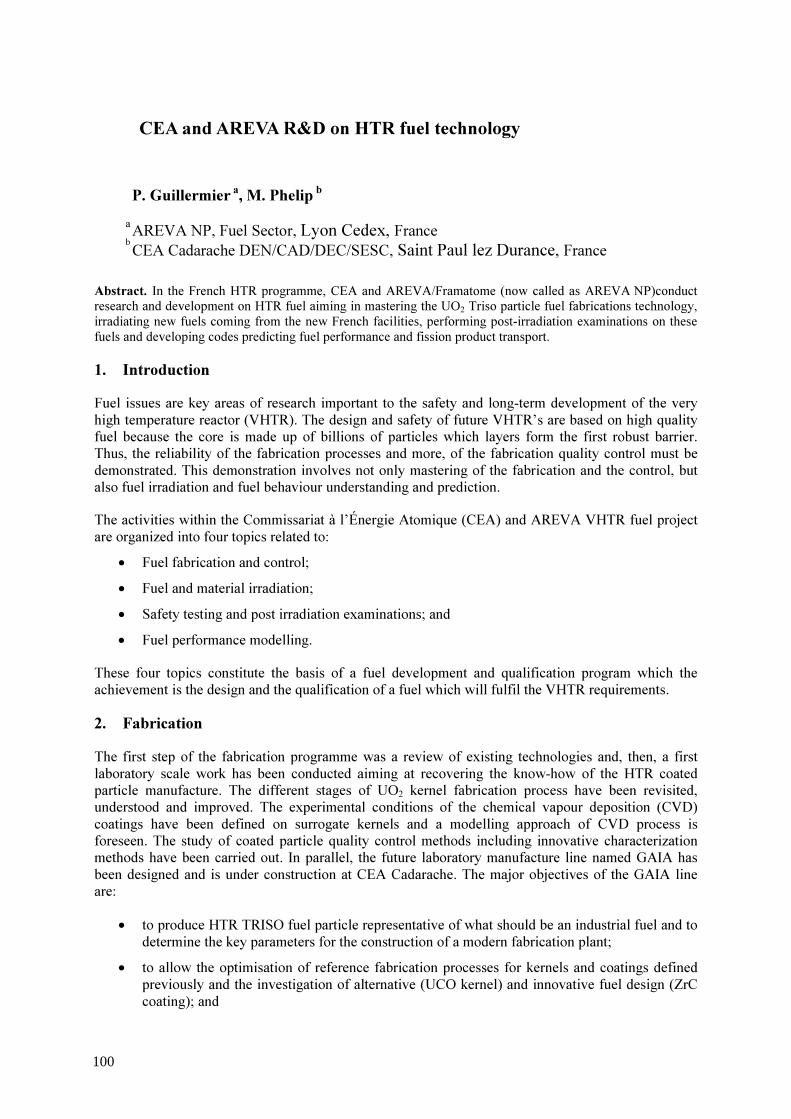
CEA and AREVA R&D on HTR fuel technology
P. Guillermier a, M. Phelip b a
b AREVA NP, Fuel Sector, Lyon Cedex, France CEA Cadarache DEN/CAD/DEC/SESC, Saint Paul lez Durance, France
Abstract. In the French HTR programme, CEA and AREVA/Framatome (now called as AREVA NP)conduct research and development on HTR fuel aiming in mastering the UO2 Triso particle fuel fabrications technology, irradiating new fuels coming from the new French facilities, performing post-irradiation examinations on these fuels and developing codes predicting fuel performance and fission product transport.
1. Introduction Fuel issues are key areas of research important to the safety and long-term development of the very high temperature reactor (VHTR). The design and safety of future VHTR’s are based on high quality fuel because the core is made up of billions of particles which layers form the first robust barrier. Thus, the reliability of the fabrication processes and more, of the fabrication quality control must be demonstrated. This demonstration involves not only mastering of the fabrication and the control, but also fuel irradiation and fuel behaviour understanding and prediction. The activities within the Commissariat à l’Énergie Atomique (CEA) and AREVA VHTR fuel project are organized into four topics related to: • Fuel fabrication and control; • Fuel and material irradiation; • Safety testing and post irradiation examinations; and • Fuel performance modelling.
These four topics constitute the basis of a fuel development and qualification program which the achievement is the design and the qualification of a fuel which will fulfil the VHTR requirements. 2. Fabrication The first step of the fabrication programme was a review of existing technologies and, then, a first laboratory scale work has been conducted aiming at recovering the know-how of the HTR coated particle manufacture. The different stages of UO2 kernel fabrication process have been revisited, understood and improved. The experimental conditions of the chemical vapour deposition (CVD) coatings have been defined on surrogate kernels and a modelling approach of CVD process is foreseen. The study of coated particle quality control methods including innovative characterization methods have been carried out. In parallel, the future laboratory manufacture line named GAIA has been designed and is under construction at CEA Cadarache. The major objectives of the GAIA line are: • to produce HTR TRISO fuel particle representative of what should be an industrial fuel and to
determine the key parameters for the construction of a modern fabrication plant; • to allow the optimisation of reference fabrication processes for kernels and coatings defined
previously and the investigation of alternative (UCO kernel) and innovative fuel design (ZrC coating); and
100
• to fabricate and to characterize first batches of coated particles for irradiation tests which Post Irradiation Examination data will feed the modelling code.
2.1. CEA & AREVA coated fuel particle description and preliminary fuel specification Based on the previous worldwide experience in HTR fuel fabrication and irradiation, preliminary fuel specification for coated fuel particles have been issued by AREVA (Table 1). Today, these fuel specifications have to be considered as guidelines for our laboratory scale R&D. Further irradiations supported by fuel modelling will allow to precise and define final fuel specifications, including alternative fuel design such as UCO kernel or more refractory fission product retention barrier such as a ZrC layer. Our present target is the manufacture of coated fuel particle composed of a 500µm diameter UO2 kernel and about 200µm thick coating layers. The overall coating consists of a porous PyC buffer layer, an inner high density isotropic PyC layer (IPyC), a high density SiC layer and an outer high density isotropic PyC layer (OPyC). TABLE 1. GUIDELINES FOR HTR FUEL MANUFACTURE
Parameter Preliminary specifications UO2 kernel Diameter (µm) 500 ± 40 Density (g.cm-3) ≥ 10.4 Sphericity < 1.1 O/U ratio 1.99 ≤ x ≤2.02 Coated fuel particle Buffer layer thickness (µm) 95 ± 20 IPyC layer thickness (µm) 40 ± 10 SiC layer thickness (µm) 35 ± 7 PyC layer thickness (µm) 40 ± 10 Buffer layer density ≤ 1.05 IPyC layer density 1.85 ≤ x ≤ 2 SiC layer density ≥ 3.18 PyC layer density 1.85 ≤ x ≤ 2 Anisotropy factor of IPyC and OPyC layers (BAF) ≤ 1.06 Heavy metal contamination (Ucont/Utotal) ≤ 10-7 Defective coating (Ufree/Utotal) ≤ 5.10-6
2.1.1. R&D on TRISO coated fuel particle manufacture The German know-how acquired in the 1980-90’s has demonstrated a high quality level manufacture of UO2 kernel with the use of the gel supported process (GSP) at an industrial scale, whereas the internal gelation process (using hexa-methylene tetra-mine (HMTA) as reactant) has only been studied at a laboratory scale, with a major handicap which is the large quantities of organic waste to be retreated. For these reasons, the GSP process has been chosen. Investigations led on each stage of the GSP process have been performed at CEA Cadarache using two laboratory scale devices, a small vertical one and a horizontal device. Experimental parameters controlling the broth preparation, the U-based droplet formation have been extensively studied and optimised. The adequate conditions of the gelation and ageing stages have been optimised. The influence of the thermal treatment atmosphere on the microstructure and the composition of the U-based sintered kernels have also been investigated in order to obtain as-specified dense UO2 kernel. Preliminary small batches of UO2 kernels have been successfully performed with characteristics (density, sphericity and diameter) fulfilling the guidelines (cf. Figs. 1, 2 and 3).
101
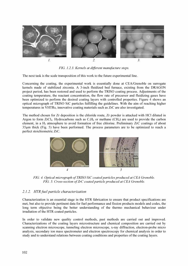
1. 2. 3. FIG. 1.2.3. Kernels at different manufacture steps.
The next task is the scale transposition of this work to the future experimental line. Concerning the coating, the experimental work is essentially done at CEA/Grenoble on surrogate kernels made of stabilized zirconia. A 3-inch fluidized bed furnace, existing from the DRAGON project period, has been restored and used to perform the TRISO coating process. Adjustments of the coating temperature, the reactant concentration, the flow rate of precursor and fluidizing gases have been optimized to perform the desired coating layers with controlled properties. Figure 4 shows an optical micrograph of TRISO SiC particles fulfilling the guidelines. With the aim of reaching higher temperatures in VHTRs, innovative coating materials such as ZrC are also investigated. The method chosen for Zr deposition is the chloride route, Zr powder is attacked with HCl diluted in Argon to form ZrCl4. Hydrocarbons such as C3H6 or methane (CH4) are used to provide the carbon element, in a H2 atmosphere to avoid formation of free chlorine. Preliminary ZrC coatings of about 35µm thick (Fig. 5) have been performed. The process parameters are to be optimized to reach a perfect stoichiometric ZrC.
4 5 FIG. 4. Optical micrograph of TRISO SiC coated particles produced at CEA Grenoble.
FIG. 5. Cross-section of ZrC coated particle produced at CEA Grenoble. 2.1.2. HTR fuel particle characterization Characterization is an essential stage in the HTR fabrication to ensure that product specifications are met, but also to provide pertinent data for fuel performance and fission products models and codes, the long term objective being the better understanding of the thermo mechanical behaviour under irradiation of the HTR coated particles. In order to validate new quality control methods, past methods are carried out and improved. Characterizations of the coating layers microstructure and chemical composition are carried out by scanning electron microscope, tunneling electron microscope, x-ray diffraction, electron-probe micro analysis, secondary ion mass spectrometer and electron spectroscopy for chemical analysis in order to study and to understand relations between coating conditions and properties of the coating layers.
102

2.1.3 Potential of the GAIA experimental HTR fuel fabrication line In parallel to the HTR fabrication R&D, an experimental manufacture line named GAIA has been designed and is now under construction at CEA Cadarache. Conception of GAIA has been thought to perform and handle batches large enough to be representative for our experimental R&D studies. Batches of 50 to 500 g U of UO2 kernels will be produced in a about 1.5 m high GSP sol-gel reactor, CVD coatings will be done in a 3” fluidized bed furnace. A 3D view of the expected CVD furnace is given in Fig. 6. The GAIA line has also been designed to be as flexible and versatile as possible in order to study different configurations of the HTR fuel fabrication process. In this perspective, the other objectives of GAIA is to allow the manufacture of wide range designs of coated fuel particles and also the investigation of alternative and innovative fuel design such as the UCO kernel and ZrC coating. At short term, GAIA installation will produce the batches of coated fuel particles for the set of SIROCCO HTR Fuel irradiation tests foreseen in the Material Testing Reactor OSIRIS at Saclay to provide data on fuel performance under irradiation and to feed the modelling code via the Post Examination Irradiation.
FIG. 6. 3D view of the expected CVD furnace. 3. Irradiation An extensive HTR Fuel irradiation program (the SIROCCO Program) is planned by CEA and AREVA: • to provide data on fuel performance under irradiation, to support fuel process development; • to qualify fuel under normal operating conditions, non operating conditions and accidental
conditions; and • to support development and validation of fuel performance and fission products transport
models and codes. This irradiation program will mainly be conducted at the French Material Testing Reactor OSIRIS (CEA, France, Saclay) with HTR fuel manufactured with the GAIA line (CEA, France, Cadarache). At the present time, the two first irradiations are well defined and under preparation. These irradiations address the first step of the qualification of the UO2/SiC reference industrial fuel.
103

FIG. 7. 3D view of the sample holder. The objectives of the first one are to verify the quality of the fuel in terms of integrity and fission products retention. Fuel description:
Type of particle UO2/Buffer/OPyC/SiC/IpyC Particle geometry German reference geometry (500/95/40/35/40 µm) Matrix geometry Compact Enrichment (%) 9.2 Packing fraction (%) ~10 (about 1500 particles per compact)
Irradiation conditions:
Fuel surface temperature ~1000 °C Fluence > 2.1025 m-2 Power density < 0.2 W/ particle Duration ~150 full power days
The fuel quality verification will consist of a direct comparison between new French particles and German particles: past best German particle fabrication will be compacted with the same CERCA process, the same packing fraction, the same enrichment and irradiated in the same device (with a separate fission gas release measurement system) under the same irradiation conditions. It will allow to fix the French new manufacture quality in comparison with the German reference with a high degree of confidence in term of fission gas release, post-irradiation examination (PIE) and safety tests. In addition, these two set of particles will be characterized before and after irradiation with the same CEA improved QC methods. The objectives of the second irradiation are to verify the aptitude of the reference particle to withstand VHTR conditions. Fuel description:
Type of particle UO2/Buffer/IPyC/SiC/OPyC Particle geometry German reference geometry (500/95/40/35/40 µm) Matrix geometry Compact Enrichment (%) ~15 Packing fraction (%) ~15 (about 2500 particles per compact)
104
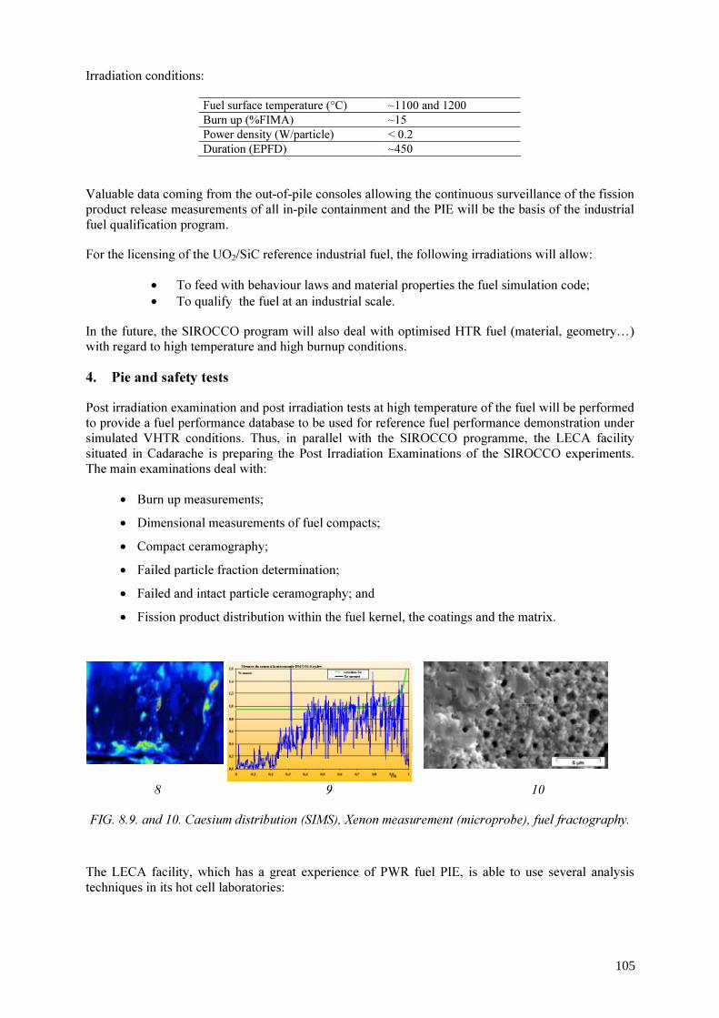
Irradiation conditions: Fuel surface temperature (°C) ~1100 and 1200 Burn up (%FIMA) ~15 Power density (W/particle) < 0.2 Duration (EPFD) ~450
Valuable data coming from the out-of-pile consoles allowing the continuous surveillance of the fission product release measurements of all in-pile containment and the PIE will be the basis of the industrial fuel qualification program. For the licensing of the UO2/SiC reference industrial fuel, the following irradiations will allow:
• To feed with behaviour laws and material properties the fuel simulation code; • To qualify the fuel at an industrial scale.
In the future, the SIROCCO program will also deal with optimised HTR fuel (material, geometry…) with regard to high temperature and high burnup conditions. 4. Pie and safety tests Post irradiation examination and post irradiation tests at high temperature of the fuel will be performed to provide a fuel performance database to be used for reference fuel performance demonstration under simulated VHTR conditions. Thus, in parallel with the SIROCCO programme, the LECA facility situated in Cadarache is preparing the Post Irradiation Examinations of the SIROCCO experiments. The main examinations deal with:
• Burn up measurements; • Dimensional measurements of fuel compacts; • Compact ceramography; • Failed particle fraction determination; • Failed and intact particle ceramography; and • Fission product distribution within the fuel kernel, the coatings and the matrix.
8 9 10 FIG. 8.9. and 10. Caesium distribution (SIMS), Xenon measurement (microprobe), fuel fractography. The LECA facility, which has a great experience of PWR fuel PIE, is able to use several analysis techniques in its hot cell laboratories:
105

• Scanning electron microscopy (SEM); • Electron microprobe; • Secondary ions mass spectrometry (SIMS); and • High resolution gamma spectrometry.
5. Fuel performance modelling CEA, in partnership with AREVA, is developing the Advanced Thermal mechanicaL Analysis Softfware (ATLAS) code with the following objectives: • To quantify, by a statistical approach, the failed particle fraction of a loading (experiment,
core) at a given time step in normal and accidental conditions. Results will be directly used to fulfil the failure fraction requirements coming from safety analysis;
• To evaluate, by a statistical approach, the fission product released fraction of a loading (experiment, core) at a given time step in normal and accidental conditions. Results will be input data for fission products transport codes;
• The methodology used is made up of three steps; • Deterministic calculations of different type of free particles, using a finite element method.
The models are one-dimensional for intact particles or particles with fully debonded layers or two-dimensional for cracked, partially debonded or shaped particles. Temperatures, displacements, stresses, strains and fission product concentrations are calculated on each node of the model;
• Deterministic calculations of a fuel element, using a finite element method with homogenised or three dimensional models. Boundary conditions for free particle, temperatures, displacements, stresses, strains and fission product concentrations are calculated on each node of the model;
• Statistical processing of the above results taking into account ceramic failure mode, but also fabrication, material property and core data uncertainties.
The particle finite element model is made up of the kernel and layers, bonded or not. In the TRISO case, the layers are buffer, IPyC, SiC and OPyC (see Fig. 11); the buffer is debonded from kernel and IPyC. The simulation takes into account the following phenomena: • Solid and gaseous kernel swelling; • Fission gas release and CO/CO2 production (LEU UO2 fuel); • Evolution of the free volume and influence on the inner pressure, gap creation around the
buffer, induced by buffer and IPyC shrinkage and variation of the conductivity of this gaseous layer, depending on produced gas;
• Irradiation induced dimensional change of the layers; • Irradiation creep and property changes of the layers.
106
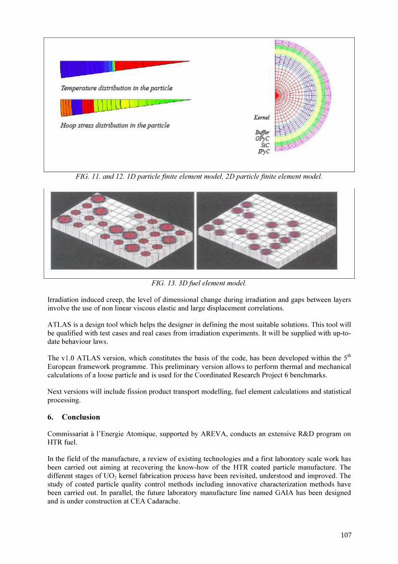
FIG. 11. and 12. 1D particle finite element model, 2D particle finite element model.
FIG. 13. 3D fuel element model.
Irradiation induced creep, the level of dimensional change during irradiation and gaps between layers involve the use of non linear viscous elastic and large displacement correlations. ATLAS is a design tool which helps the designer in defining the most suitable solutions. This tool will be qualified with test cases and real cases from irradiation experiments. It will be supplied with up-to-date behaviour laws. The v1.0 ATLAS version, which constitutes the basis of the code, has been developed within the 5th European framework programme. This preliminary version allows to perform thermal and mechanical calculations of a loose particle and is used for the Coordinated Research Project 6 benchmarks. Next versions will include fission product transport modelling, fuel element calculations and statistical processing. 6. Conclusion Commissariat à l’Energie Atomique, supported by AREVA, conducts an extensive R&D program on HTR fuel. In the field of the manufacture, a review of existing technologies and a first laboratory scale work has been carried out aiming at recovering the know-how of the HTR coated particle manufacture. The different stages of UO2 kernel fabrication process have been revisited, understood and improved. The study of coated particle quality control methods including innovative characterization methods have been carried out. In parallel, the future laboratory manufacture line named GAIA has been designed and is under construction at CEA Cadarache.
107
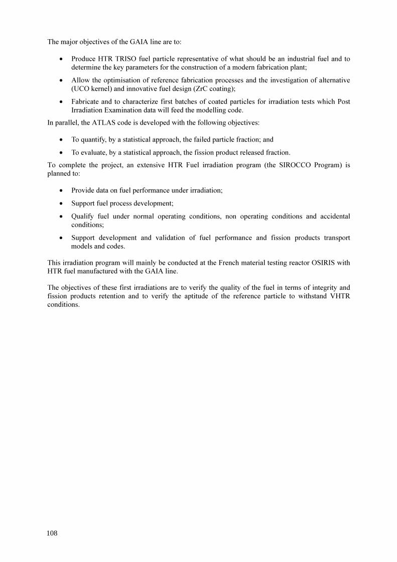
The major objectives of the GAIA line are to: • Produce HTR TRISO fuel particle representative of what should be an industrial fuel and to
determine the key parameters for the construction of a modern fabrication plant; • Allow the optimisation of reference fabrication processes and the investigation of alternative
(UCO kernel) and innovative fuel design (ZrC coating); • Fabricate and to characterize first batches of coated particles for irradiation tests which Post
Irradiation Examination data will feed the modelling code. In parallel, the ATLAS code is developed with the following objectives: • To quantify, by a statistical approach, the failed particle fraction; and • To evaluate, by a statistical approach, the fission product released fraction.
To complete the project, an extensive HTR Fuel irradiation program (the SIROCCO Program) is planned to: • Provide data on fuel performance under irradiation; • Support fuel process development; • Qualify fuel under normal operating conditions, non operating conditions and accidental
conditions; • Support development and validation of fuel performance and fission products transport
models and codes. This irradiation program will mainly be conducted at the French material testing reactor OSIRIS with HTR fuel manufactured with the GAIA line. The objectives of these first irradiations are to verify the quality of the fuel in terms of integrity and fission products retention and to verify the aptitude of the reference particle to withstand VHTR conditions.
108

Overview of R&D activities of HTR fuel in China
Tang Chunhe Institute of Nuclear Energy Technology, Tsinghua University Beijing, P. R. of China
Abstract. High temperature gas-cooled reactor (HTGR) is recognized as an advanced type of reactor with its inherent safety feature, fuel cycle flexibility, high fuel utilization, high efficient electricity generation and process heat application. The fuel element of the HTGR is all-ceramic type, and is crucial for the safety and reliable operation of the HTGR. Therefore, R&D activities for HTGR and its fuel element started from the middle of 1970’s in China, and have begun to be a part of China high technology program since 1986. R&D work of HTGR fuel element was carried out in experimental scale before 1991. Since 1991 R&D activities have been focused on fabrication technology for Chinese 10 MW high temperature gas-cooled reactor (HTR-10) first core fuel. During long-term R&D activities, Institute of Nuclear Energy Technology, Tsinghua University (INET) has successfully developed own fabrication technologies of spherical fuel elements for HTR-10. Over 20 000 spherical fuel elements have been fabricated in 2000 and 2001. The performance of the fabricated fuel elements meets the design requirement of HTR-10 fuel.
1. Introduction The 10 MW high temperature gas-cooled reactor (HTR-10) is a modular pebble-bed type high temperature gas-cooled reactor. Spherical fuel elements are used in the pebble-bed core [3]. The spherical fuel element with 60 mm in diameter consists of the matrix graphite and nearly 10 000 coated fuel particles. The matrix graphite, which serves as neutron moderator as well as a heat conductor from the fuel to the coolant gas, consists of 64% natural flake graphite, 16% electric graphite and 20% phenol resin binder. The key ingredient of the HTGR fuel element is the coated fuel particle which serves as a miniature fission product containment vessel. Over the last 40 years, the progress of the coated fuel particle from the laminar (a single pyrolytic carbon layer), the BISO (two isotropic coating materials) to the TRISO (triple isotropic coating materials) has been made. Now the LEU (low enriched uranium) TRISO coated particle fuel is adopted in all countries engaged in the HTGR program. The coated fuel particle of the LEU TRISO–type having a 0.92mm-diameter is composed of a central low enriched UO2 kernel and four layers. These four layers are (1) a low-density porous pyrolytic carbon (PyC) buffer layer, (2) an inner high-density isotropic PyC layer, (3) a SiC layer and (4) an outer high-density isotropic PyC layer which are refractory ceramic materials to act to contain the fission products. The fabrication process for the HTR-10 spherical fuel has been developed through long-term R&D activities in the past 20 years [2,3]. The fabrication process includes UO2 kernel preparation through the modified gel precipitation, PyC and SiC coating on the UO2 kernel surface by the chemical vapour deposition and the manufacture of the spherical fuel element by the quasi-isostatic process. 2. Technology development of the HTGR in China The HTGR fuel element is the important part of the HTGR. Therefore, the development of the HTGR and its fuel element would supplement each other. Under the support of the government, the R&D activities of the HTGR in China started in the middle of 1970’s, and have begun to be a part of China high technology project since 1986. In 1992, HTR-10 was approved by the government to be one of the national high technology project. The main objective and main parameters of the HTR-10 are
109

listed in Table 1 and 2, respectively. The first criticality of the HTR-10 was reached in December 2000. TABLE 1. THE MAIN OBJECTIVE OF THE HTR-10
1 To thoroughly understand HTGR design and technology 2 To carry out irradiation tests for fuel elements and other materials 3 To verify the inherent safety features of the Modular HTGR 4 To provide electricity and district heating 5 To develop high temperature
TABLE 2. MAIN PARAMETERS OF HTR-10 Reactor thermal power MW 10 Active core volume m3 5 Average power density MW/ m3 2 Primary helium pressure MPa 3 Helium inlet temperature °C 250/300 Helium outlet temperature °C 700/900 Helium mass flow rate kg/s 4.3/3.2 Fuel UO2 Diameter of spherical fuel elements mm 60 U-235 enrichment of fresh fuel elements % 17 Number of spherical fuel elements 27 000 Refueling mode Multi-pass Average discharge burnup MWd/tU 80 000
3. R&D activities on HTGR fuel in China The fuel element is an important part of the HTGR. Therefore, it is prerequisite for constructing HTR to be able to fabricate the qualification fuel elements. So R&D activities of the HTGR fuel in China started in the middle of 1970’s, too. The technology development of the HTGR fuel in China can be divided roughly in four phases, as shown in Table 3.
110
TABLE 3. TECHNOLOGY DEVELOPMENT OF THE HTGR FUEL IN CHINA Development Phase
R&D Activities
First phase (1974~1986)
comprehensive R&D activities in laboratory scale in INET and Nuclear Power Institute of China (NPIC): ·Fuel kernel preparation (UO2 and ThO2 kernel) —sol-gel process (internal and external gelation process) —Weak-acid ion exchange resin method ·Coated fuel particle fabrication (BISO and TRISO) —low temperature deposition from C3H6 —high temperature deposition from CH4 ·Fuel element manufacture (block-type and sphere) —pressing —machining ·Various inspection methods
Second phase (1987~1991)
· R&D was focused on LEU TRISO fuel in laboratory scale in INET and NPIC: —UO2 kernel preparation (external and internal gelation process) —PyC and SiC coating in 2” fluidized bed (low temperature deposition and high temperature deposition) —Spherical fuel element (quasi- isostatic and isostatic pressing) —Main raw materials (natural graphite powder and phenolic resin) · Improvement of inspection method and instrument and equipment · Irradiation testing of coated fuel particles(R/B : 10-6~10-7) · LEU TRISO spherical fuel element was successfully fabricated in laboratory scale, and its performance can meet the design requirement of HTGR fuel.
Third phase (1992~1999)
Production preparation and experiment in production scale: • Constructing permit of fuel production workshop was approved by National Environmental Protection Administration. • Fabrication technology for HTR-10 was established : — UO2 kernel through modified gel precipitation; — PyC and SiC coating by low temperature CVD (C3H6); — Spherical fuel element manufacture through quasi–isostatic pressing. • NUKEM equipment was imported, and production line with the production ability of 20 000 spherical fuel elements/year was installed. • All inspection methods and instruments were built. • Irradiation protection, criticality safety and physical protection system were set up. • Technical and batch experiments of UO2 kernel, coated particle and spherical fuel elements in production scale were completed, and fabrication process parameters were set up. • QA and QC for fuel production was established. · Irradiation testing of some coated fuel was carried out (Oct.1990~April 1997) in Juelich. • HTR-10 fuel fabrication license was issued by NNSA. • Irradiation samples for irradiation testing in Russia were fabricated.
Fourth phase (2000~2004)
Fabrication of HTR-10 first loading fuel in laboratory scale and irradiation testing of HTR-10 fuel Over 20 000 spherical fuel elements was produced for HTR-10 first fuel loading: • The statistical data of 44 batches of UO2 kernels and coated particles for HTR-10 first loading were summarized in Table 4. • The statistical data of 44 batches of spherical fuel spheres and graphite matrix balls for HTR-10 first loading was shown in Table 5. • The average free uranium fraction is 4.6×10⁻⁵. An in-pile testing of 2 spherical fuel elements randomly selected from the No.F1 and another 2 from No.F2 batch was carried out in the Russian IVV-2M research reactor. •The maximum burnup and fast neutron fluence reached 107 000 MWd/tU and 1.31×1025 m –2, respectively in this test.
111

TABLE 4. STATISTICAL PERFORMANCE DATA OF COATED FUEL PARTICLE
Performance item Mean value of lots
Standard deviation of mean value of lots
Standard deviation of all samples
UO2 Kernel Diameter (µm) 497.8 7.1 14.8 Density (g/cm3) 10.80 0.055 -- Sphericity 1.043 0.009 0.027 O/U ratio 2.00 0 -- Equivalent B content (µg/g) 0.24 0.14 -- Coated fuel particle Buffer layer thickness (µm) 99.1 7.2 11.9 IPyC layer thickness (µm) 41.7 3.2 4.3 SiC layer thickness (µm) 36.7 1.9 2.6 OPyC layer thickness (µm) 42.6 2.0 4.8 Buffer layer density (g/cm3) 0.98 0.07 -- IPyC layer density (g/cm3) 1.85 0.02 -- SiC layer density (g/cm3) 3.20 0.003 -- OPyC layer density (g/cm3) 1.86 0.03 -- IPyC layer anisotropy 1.025 0.005 -- OPyC layer anisotropy 1.023 0.005 --
TABLE 5. STATISTICAL PERFORMANCE DATA OF SPHERICAL FUEL ELEMENT Performance item Mean value of lots Standard deviation of mean
value of lots Graphite matrix ball Density (g/cm3) 1.75 0.012 Total ash (μg/g) 82.4 19.5 Li content (μg/g) 0.001 0.001 Equivalent B content (μg/g) 0.90 0.52 Thermal conductivity, at 1000oC (W/cm⋅K)
⊥: 0.292 //: 0.287
0.018 0.017
Corrosion rate, 1000oC He + 1vol%H2O(mg/cm2·h)
0.91
0.18
Erosion rate (mg/ball ·h) 2.8a 0.6 Number of drops (4m in height) >100 -- Crushing strength (KN) ⊥: 23.5
//: 25.0 1.0 1.3
Anisotropy(coefficient of thermal expansion), α⊥/α//
1.06
0.04
Spherical fuel element Diameter (mm) 59.6~60.2 -- Thickness of fuel-free shell (mm) 4.0~6.0 -- U loading (g U/ball) 5.01 0.042 U contamination of graphite matrix ball 6.4×10⁻⁷ 7.0×10⁻⁷ Free U fraction (Ufree /Utotal) 4.6×10⁻⁵ 6.1×10⁻⁵
⊥ and //: indicate perpendicular to and parallel to the C-axis orientation, respectively. a: measured after 100 h in a rotating drum containing 20 spheres. b: measured after 20 h in a rotating drum containing 20 spheres.
4. Planed activities of particle fuel The Chinese nuclear energy science and technology company, which is established by the cooperation of INET, will construct a 160 MWe High temperature reactor-prototype module (HTR-PM). This reactor is planed to reach its criticality in 2010. In order to match the construction of this reactor, our main task is to resolve the technical problems from HTR-10 fuel to HTR-PM fuel, construct the HTR
112

fuel plant and fabricate fuel element recently. The HTGR fuel with high performance will be the main objective of INET R&D activities for HTGR fuel in future. 5. Summary Main R&D activities of HTGR fuel in China go through about 20 years from laboratory scale, production scale to fabricating fuel for HTR-10 first loading. Through R&D activities of HTGR fuel, INET has gained considerable experience on the HTGR fuel. The fabrication of HTR-10 first loading fuel has been finished. The fuel performance satisfies the design requirement of HTR-10 fuel. During the process of the fuel fabrication, the fuel quality was gradually improved. The free-uranium contents of the fist 10 batches, from 11 to 44 batches and average of total 44 batches are 1.1×10⁻⁴, 2.7×10⁻⁵ and 4.6×10⁻⁵, respectively. To match the construction of HTR-PM, we will build a HTR fuel plant with the production capability of 250 000 to 300 000 spherical fuel elements. The HTGR fuel with high performance will be the main objective of INET R&D activities for HTGR fuel in future.
REFERENCES
[1] NICKEL, E., BALTHESEN, E., Status of HTR fuel element development in the FRG and its potential for nuclear process heat reactor, Kerntechnik 17, (1975) 205-214.
[2] TANG, C.H., TANG, Y.P., ZHU, J., QIU, X., LI, J., XU, S., Research and development of fuel element for Chinese 10 MW high temperature gas-cooled reactor, Journal of Nuclear Science and Technology 37 (2000) 802-806.
[3] TANG, C.H., TANG, Y.P., ZHU, J., ZOU, Y., LI, J., NI, X., Design and Manufacture of the Fuel Element for the 10 MW High Temperature Gas-cooled Reactor, Nuclear Engineering and Design, 218 (2002) 91-102.
113

Session 2
COATED PARTICLE FUEL MODELLING
A. Chernikov Russian Federation
Y.W. Lee
Republic of Korea

TRISO particle fuel performance code benchmarking activities performed under the IAEA 6th coodinated rsearch programme on advances in HTR fuel technology
M. Phelipa, I. Kadarmetovb, D. Pettic, H. Nabielekd, K. Verfondernd, T. Abrame a b
c d e
Commissariat à l’Energie Atomique, Cadarache, France A.A. Bochvar, All-Russian Research Institute of Inorganic Materials, Moscow, Russian Federation Idaho National Engineering and Environmental Laboratory, Idaho Falls, USA Forschungszentrum Juelich, Juelich, Germany British Nuclear Fuels plc, Springfields, United Kingdom
Abstract. A key part of the IAEA 6th Coordinated Research Project on advances in high temperature reactor (HTR) fuel technology includes benchmarking of fuel performance models under normal and accident conditions. The normal operation and accident behaviour benchmarks have been structured in two phases. In the first phase, a series of simplified analytical benchmarking problems have been established for both normal and accident conditions as a way to “calibrate” all of the codes and/or models. In the second phase, the codes and/or models will be used to calculate fuel behaviour in past and future irradiation experiments and heating tests. Current participants in the benchmark include England, France, Germany, Russia and the United States. This paper will present a status of this international code benchmarking activity.
1. Introduction Over the past few years, there has been a worldwide growing interest in nuclear technology and programmes related to the design of innovative nuclear reactor systems with a high level of safety and also the potential of extending the applicability range to areas such as process heat production or burning stockpile plutonium. International initiatives like the “Generation IV International Forum” (GIF) or the “International Project on Innovative Nuclear Reactors and Fuel Cycles” (INPRO) have significantly influenced discussions on international R&D programmes. A particular focus is put on the high temperature reactor (HTR) technology that was selected as reactor type to meet the requirements of a Generation IV nuclear system. An aspect of utmost importance is the HTR fuel technology. Based on the acquired knowledge from the past, the operational experience with two research-type HTRs operated presently in Japan and China; research programmes are being pursued in various countries which are related to fuel development, irradiation, accident simulation testing, and modelling. Potential gains can arise from advanced fuel design and fabrication methods and quality control with specific interest in achieving higher (than 10% FIMA) burnups, qualifying for higher (than 1600°C) temperatures, and enlarging the data bases. A concomitant effort is development work for fuel performance models as a qualified tool to predict the behaviour of HTR fuel under normal and off-normal operation conditions. 2. Objectives of the IAEA coordinated research programme #6 The need for a new IAEA directed coordinated research project (CRP) on HTR fuel was first expressed on a meeting of the technical working group on gas cooled reactors in June 2000. An IAEA consultancy meeting in Petten, NL, in April 2002 with a total of 27 specialists from 9 countries gathered to set the basis for the proposal of a CRP on “Advances in HTR Fuel Technology Development” and define its scope of activities. This CRP, being the No. 6 in the chronological sequence of all coordinated research projects, has been eventually approved by the IAEA as an un-
117
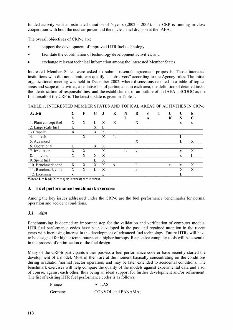
funded activity with an estimated duration of 5 years (2002 – 2006). The CRP is running in close cooperation with both the nuclear power and the nuclear fuel division at the IAEA. The overall objectives of CRP-6 are: • support the development of improved HTR fuel technology; • facilitate the coordination of technology development activities; and • exchange relevant technical information among the interested Member States. Interested Member States were asked to submit research agreement proposals. Those interested institutions who did not submit, can qualify as “observers” according to the Agency rules. The initial organizational meeting was held in December 2002, where discussions resulted in a table of topical areas and scope of activities, a tentative list of participants in each area, the definition of detailed tasks, the identification of responsibilities, and the establishment of an outline of an IAEA-TECDOC as the final result of the CRP-6. The latest update is given in Table 1. TABLE 1. INTERESTED MEMBER STATES AND TOPICAL AREAS OF ACTIVITIES IN CRP-6
Activit C h
F G J K N L
R S A
T U K
U S
E C
1. Plant concept fuel X X L X X X x x 2. Large scale fuel L X L 3 Graphite X X X L 4. tech. X X L L 5. Advanced X L X 6. Operational L X X 7. Irradiation X X X L x x X 8. cond X X X X x L 9. Spent fuel L X 10. Benchmark cond X X X X x L x x X 11. Benchmark cond X X L X x X X 12. Licensing x x L
Where L = lead; X = major interest; x = interest
3. Fuel performance benchmark exercises Among the key issues addressed under the CRP-6 are the fuel performance benchmarks for normal operation and accident conditions. 3.1. Aim Benchmarking is deemed an important step for the validation and verification of computer models. HTR fuel performance codes have been developed in the past and regained attention in the recent years with increasing interest in the development of advanced fuel technology. Future HTRs will have to be designed for higher temperatures and higher burnups. Respective computer tools will be essential in the process of optimization of the fuel design. Many of the CRP-6 participants either possess a fuel performance code or have recently started the development of a model. Most of them are at the moment basically concentrating on the conditions during irradiation/normal reactor operation, and may be later extended to accidental conditions. The benchmark exercises will help compare the quality of the models against experimental data and also, of course, against each other, thus being an ideal support for further development and/or refinement. The list of existing HTR fuel performance codes is as follows: France ATLAS; Germany CONVOL and PANAMA;
118
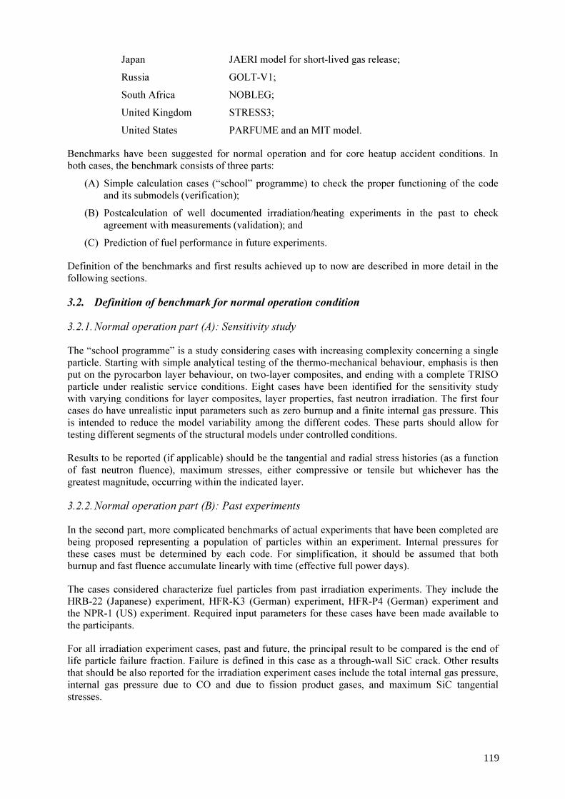
Japan JAERI model for short-lived gas release; Russia GOLT-V1; South Africa NOBLEG; United Kingdom STRESS3; United States PARFUME and an MIT model. Benchmarks have been suggested for normal operation and for core heatup accident conditions. In both cases, the benchmark consists of three parts:
(A) Simple calculation cases (“school” programme) to check the proper functioning of the code and its submodels (verification);
(B) Postcalculation of well documented irradiation/heating experiments in the past to check agreement with measurements (validation); and
(C) Prediction of fuel performance in future experiments. Definition of the benchmarks and first results achieved up to now are described in more detail in the following sections. 3.2. Definition of benchmark for normal operation condition 3.2.1. Normal operation part (A): Sensitivity study The “school programme” is a study considering cases with increasing complexity concerning a single particle. Starting with simple analytical testing of the thermo-mechanical behaviour, emphasis is then put on the pyrocarbon layer behaviour, on two-layer composites, and ending with a complete TRISO particle under realistic service conditions. Eight cases have been identified for the sensitivity study with varying conditions for layer composites, layer properties, fast neutron irradiation. The first four cases do have unrealistic input parameters such as zero burnup and a finite internal gas pressure. This is intended to reduce the model variability among the different codes. These parts should allow for testing different segments of the structural models under controlled conditions. Results to be reported (if applicable) should be the tangential and radial stress histories (as a function of fast neutron fluence), maximum stresses, either compressive or tensile but whichever has the greatest magnitude, occurring within the indicated layer. 3.2.2. Normal operation part (B): Past experiments In the second part, more complicated benchmarks of actual experiments that have been completed are being proposed representing a population of particles within an experiment. Internal pressures for these cases must be determined by each code. For simplification, it should be assumed that both burnup and fast fluence accumulate linearly with time (effective full power days). The cases considered characterize fuel particles from past irradiation experiments. They include the HRB-22 (Japanese) experiment, HFR-K3 (German) experiment, HFR-P4 (German) experiment and the NPR-1 (US) experiment. Required input parameters for these cases have been made available to the participants. For all irradiation experiment cases, past and future, the principal result to be compared is the end of life particle failure fraction. Failure is defined in this case as a through-wall SiC crack. Other results that should be also reported for the irradiation experiment cases include the total internal gas pressure, internal gas pressure due to CO and due to fission product gases, and maximum SiC tangential stresses.
119

3.2.3. Normal operation part (C): Future experiments The third part encompasses future irradiation experiments. Nominal parameters aimed at in these tests have also been provided. The experiments suggested include HFR-EU1, HFR-EU2 (both tests planned to start in 2004), AGR-1 (planned US experiment, details not yet available), and perhaps other experiments to be determined. 3.3. Definition of benchmark for core heatup accident condition 3.3.1. Accident condition part (A): Sensitivity study The calculations suggested for the “school programme” represent a typical sensitivity study. Based on a single reference case, both irradiation parameters and accident conditions will be varied to examine their influence on the failure probability of fuel particles. The assumption of an irradiation time of 500 efpd, three different irradiation temperatures (800, 1000, 1200 °C), two different combinations of burnup/fast neutron fluence (5 %FIMA and 2x1025 m-2, E>0.1 MeV; 10 and 4), and three isothermal heating temperatures (1600, 1700, 1800 °C) over 100 h of heating time make it a total of 18 cases. The exception from this “regular” scheme: For the cases of high burnup and 1000 °C irradiation temperature, instead of considering three heating temperatures, three different heatup ramp rates to reach 1800 °C (18, 48 as reference, 183 K/h) should be applied. 3.3.2. Accident condition part (B): Past experiments For the code validation part, six cases of well documented irradiation and heating experiments have been proposed. From the former German programme, it is HTR fuel irradiated in the HFR Petten to comparatively high burnups/fluences with properly defined irradiation conditions and later heated in the KUEFA furnace at the Research Centre Jülich. These are the fuel spheres HFR-K3/1 heated at 1600 °C over 500 h and HFR-K3/3 heated at 1800 °C over 100 h. Furthermore there are “small” fuel spheres, which were part of the HFR-P4 irradiation test. The samples HFR-P4/1-12 and -P4/3-7 were both heated at 1600 °C over 304 h. Finally two more cases refer to Japanese fuel inserted in the HRB-22 irradiation test and afterwards in accident simulation tests in the US Core Conduction Cooldown Test Facility, CCCTF, where 25 single particles each were heated at 1600 and 1700 °C, respectively, over more than 200 h. 3.3.3. Accident condition part (C): Future experiments The ideal candidates for fuel performance predictions appear to be the fuel spheres from the high burnup irradiation tests HFR-EU1 (still to be done) and FRJ2-K15 (irradiation in DIDO reactor Juelich completed) because of their well defined irradiation phase. Some of these spheres are planned to be heated in the KUEFA furnace at the ITU Karlsruhe. The heating programme has not been detailled yet, but it will certainly be in the heating temperature range of 1600 – 1800 °C, conducted in a similar way as was successfully done in the former Juelich programme. Other candidates for predictive calculations are fuel compacts of US design still to be irradiated in the HFR-EU2 test (containing German coated particles) or the even still to be fabricated fuel planned for being inserted in the US experiment AGR-1 (AGR stands for a future US HTGR design with helium cooling). 4. First results 4.1. Benchmark cases for normal operation First calculations within the frame of the benchmark for normal operating conditions have been conducted by interested participating Member States. Focus was on the prediction of fuel performance during the irradiation experiment HFR-EU1. The five codes CONVOL, PANAMA, GOLT-V1, STRESS-3, and PARFUME have been applied to assess coated particle behaviour for this test at very
120

high burnups. In addition, the ATLAS code has been applied to the conditions of the HFR-P4 experiment. The HFR-EU1 is a high burnup irradiation experiment in the HFR Petten planned to be starting in 2004. Three spherical fuel elements from the latest German production plus two fuel spheres from recent Chinese production in separate capsules are to be irradiated to a maximum burnup of 20% FIMA and somewhat less for the Chinese fuel, respectively. Basic assumptions for the predictive calculations were:
Irradiation time: 600 efpd; Irradiation temperature: 950 °C surface, 1 100 °C centre; Maximum burnup: 20% FIMA; Maximum fast fluence: 6x1025 m-2, E>0.1 MeV.
Some of the results are summarized in Fig. 1. The PANAMA code represents a simple thin shell pressure vessel with SiC as the only layer considered. Assuming an SiC strength of 834 MPa and a Weibull modulus of 8.02, both in the unirradiated state), PANAMA predicts the first particle in a German sphere to fail (which is about equivalent to reaching a failure fraction level of 10-4) at a burnup between 14% FIMA (Tirr = 1100 °C) and 20% FIMA (Tirr = 950 °C). The failure probability of particles in the Chinese fuel elements is predicted to be somewhat lower due to a smaller kernel diameter and thicker buffer and SiC layers. The Russian GOLT-V1 code includes the modelling of both SiC and pyrocarbon layers assuming temperature and fluence dependence of PyC parameters as well as an irradiation induced dimensional change. Calculations for the HFR-EU1 test were conducted for different sets of Weibull parameters. The results revealing a strong dependence on material properties show the first particle to fail between 14 and 16% FIMA (Weibull parameter comparable to PANAMA calculation), and at > 10% FIMA for the cases of lower SiC strength data. Calculations with the UK code STRESS3 in connection with the statistical code STAPLE consider the particle kernel and all layers of the TRISO coating. The effect of kernel swelling with burnup is taken into account as well as the variability in the layer thicknesses. A first STRESS3 calculation with mean particle specifications indicates that the fracture stress of the SiC layer of assumed 392 MPa will be reached in the burnup range of about 21-24% FIMA depending on the assumed swelling rate. Applying the STAPLE code with statistical variations in the layer thicknesses, involving some 106 STRESS3 computer runs, results in a failure fraction exceeding the level of 10-4 (or 1 failed particle) near 14% FIMA. A significant improvement of this value could be achieved, if the large variability of the buffer layer thickness would be reduced. The US code PARFUME includes two modes for a particle to fail, apart from the traditional pressure vessel failure, also an SiC failure caused by irradiation-induced shrinkage cracking in the IPyC layer is considered. Furthermore there are two options of calculating CO pressure; with the two irradiation temperatures and two sets of Weibull data (σmed= 873 MPa, m=8.02 and σmed= 409 MPa, m=6.0), a total of 8 predictive calculations have been conducted. The internal pressures based on the two CO pressure options were calculated to be about 100 and 25 MPa for Tirr = 1100 °C, and 60 and 15 MPa for Tirr = 950 °C, respectively. Internal gas pressure dominated in most cases the total failure probability. Predicted failure fractions of 20% FIMA burnup particles vary in a wide range between 4x10⁻⁸ and 0.43 because of differences in gas pressure and SiC strength.
121

FIG. 1. Prediction of coated particle failure probability for HFR-EU1 irradiation test with different computer models.
122

4.2. Benchmark cases for core heatup accident With respect to the benchmark exercise for accident conditions, there is currently only one code, PANAMA, prepared for being applied. Other computer models developed primarily for normal operation conditions, are planned to be extended to accident conditions in a second stage and may later join the competition. PANAMA postcalculations conducted so far are related to the irradiation and heating tests HFR-K3 and HFR-P4. The specimens, four “normal” fuel spheres and 12 small spheres, respectively, were irradiated to high burnups and high neutron fluences. Some of them have undergone a heating programme and were postexamined in great detail (see Table 1). Furthermore predictive calculations have been done for a tentative heating programme with spheres from the HFR-EU1 and FRJ2-K15 experiments (see also Table 2). These results, however, are of preliminary character, until a heating programme has been precisely defined. The predictions of particle failures in the FRJ2-K15 test with PANAMA as shown in Fig. 2 were done for the irradiation temperatures 800 and 900 °C as the surface and centre temperatures of the fuel in capsules 1 and 3; the temperature range in capsule 2 was from 950 to 1050 °C. The results show that the first particle is expected to fail between 100 and 200 h into the heating phase at 1600 °C. For sphere 2, the failure level of 10-4 would be reached already after a few hours at 1600 °C (not shown). Fission gas release fractions, if Tirr = 900 °C is assumed, were estimated to be 0.1% after 300h at 1600 °C and 8% after additional 182 h at 1800 °C. TABLE 2. BENCHMARK CASES FOR ACCIDENT CONDITIONS
Case Heating programme Name Burnup
[% FIMA] Fast neutron fluence [1025, E>0.1 MeV]
Temperature T [°C]
Ramp rate to reach T [K/h]
Time at T [h]
HFR-P4- 1-12
11.1 5.5 1600 ~ 47 (1250-1600 in 7.5h)
304
HFR-P4- 3-7
13.9 7.5 1600 ~ 47 (1250-1600 in 7.5h)
304
HFR-K3/1 7.5 4.0 1600 ~ 144 (300-1600 in 9h)
500
HFR-K3/3 10.6 5.9 1800 ~ 46 (1250-1800 in 9.5h)
100
HFR-EU1 20 6 1600 / 1800 ~ 50 / ~ 94 (1000-1600 in 12h) (300-1800 in 16h)
100 / 100
FRJ2-K15/ 1 and 3
16 0.2 1600 / 1800 ~ 50 / ~ 100 (1250-1600 in 7h) (1600-1800 in 2h)
300 / 182
123
FIG. 2. Prediction of fuel performance for FRJ2-K15/1,3 if heated at 1600 and 1800 °C.
5. Conclusions and future work In the recent coordinated research project on “Advances in HTR Fuel Technology”, two ambitious benchmark proposals on fuel performance during normal operation and under accident conditions have been suggested. They represent an essential part of code validation and verification work which is necessary for the development of fuel technology for future HTRs. The high burnup irradiation test HFR-EU1 is an actual example and ideal for both benchmarks. First calculation results reveal a broad range of uncertainty over several orders of magnitude in the predicted fuel particle failure probability. This is due: (i) to the large temperature difference between surface and centre temperature typically used as lower and upper limit, respectively, (e.g., PANAMA); (ii) to different approaches in submodels of the codes (e.g., CO pressure calculation in PARFUME), or; (iii) to not well known Weibull statistical distribution of stresses in the coating layers (e.g., GOLT-V1). Future Work needs to concentrate on those parts of the benchmarks describing validation and verification of the various computer models applied: - to demonstrate and check code modelling and submodelling; - to compare with existing experimental data obtained with real HTR fuel; and - to evaluate HFR-EU1 predictions after the test.
124

APPENDIX: OUTLINE OF IAEA TECDOC “ADVANCES IN HTGR FUEL TECHNOLOGY” Draft version as of June 2004. FOREWORD 0. INTRODUCTION 1. DEFINITION AND BASIS OF PLANT CONCEPT FUEL DESIGNS [Verfondern, Kadarmetov] [50p] 1.1. Present Fuel Designs for High-Temperature Gas-Cooled Reactors 1.1.1. Experience with Fuel Concepts for Existing Reactors (HTTR, HTR-10, etc.) 1.1.2. Reference Fuel Concepts for Future Reactors (oxide/carbide fuel) (PBMR, GT-MHR, ADS, etc.) 1.2. The VHTR – A Generation IV Nuclear Energy System 1.2.1. VHTGCR (GA + Framatome) 1.2.2. MHR (GA) 1.2.3. APBR (FZJ) 1.2.4. A-HTR (JAERI) 1.3. Advanced Fuel Design Parameters
1.3.1. Main Fuel Design Parameters (Kernel diameter, coating layer thicknesses, additional layers)
1.3.1.1. Uranium Fuel 1.3.1.2. Plutonium Fuel
1.3.2. Perspective fuel designs 1.3.2.1. Fuel Development in China 1.3.2.2. Fuel Development in Europe 1.3.2.3. Fuel Development in Japan 1.3.2.4. Fuel Development in Russia/USA 1.3.2.5. Fuel Development in South Africa
1.4. Advanced Fuel Materials 1.4.1. Fission Materials (Kernels technology, enrichment, composition, stoichiometry, porosity etc.,
Pu fuel, ADS fuel) 1.4.1.1. China 1.4.1.2. Europe 1.4.1.3. Japan 1.4.1.4. Russia/USA 1.4.1.5. South Africa
1.4.2 Advanced Coating Materials (for example ZrC)
1.4.2.1. China 1.4.2.2. Europe 1.4.2.3. Japan 1.4.2.4. Russia/USA 1.4.2.5. South Africa
1.5. Conclusions 2. LARGE SCALE FUEL PRODUCTION, CHARACTERIZATION, IRRADIATION TESTING, IN-REACTOR PERFORMANCE (AVR, HTTR, HTR-10) [Tang] [40p] 2.1. Design Specifications
2.1.1. Design Specification of the HTR-10 Fuel Elements 2.1.2. Design Specification of the LEU-TRISO Fuel Elements Loaded into AVR
125
2.1.3. Design Specification of the HTTR Fuel Elements 2.2. Fabrication Processes
2.2.1. Key Fuel Problems and Possible Ways for Solution 2.2.2. Fabrication process of the HTR-10 Fuel Elements 2.2.2.1. UO2 Kernel Fabrication Process 2.2.2.2. PyC and SiC Coating Process 2.2.2.3. Manufacture Process of the Spherical Fuel Elements 2.2.3. Fabrication Process of the LEU-TRISO Fuel Elements Loaded into AVR 2.2.3.1. UO2 Kernel Fabrication Process 2.2.3.2. PyC and SiC Coating Process 2.2.3.3. Manufacture Process of the Spherical Fuel Elements
(NUKEM production of LEU UO2 TRISO fuel for the HTR-Modul) 2.2.4. Fabrication process of the HTTR Fuel Elements 2.2.4.1. UO2 Kernel Fabrication Process 2.2.4.2. PyC and SiC Coating Process 2.2.4.3. Manufacture Process of the Fuel Compacts 2.2.5. Fabrication process of HTGR Fuel in Russia 2.2.6. Fabrication process of HTGR Fuel in South Africa
(First experiences) 2.2.7. Fabrication process of the HTGR Fuel in the USA
(Production of HEU (Th,U)C2 and ThC2 TRISO fuel for Fort St. Vrain) 2.2.7.1. UO2 Kernel Fabrication Process 2.2.7.2. PyC and SiC Coating Process 2.2.7.3. Manufacture Process of the Block-Type Fuel Elements
2.3. Characterization of UO2 Kernel, Coated Fuel Particle and Spherical Fuel Element or Compact 2.3.1. Characterization of the HTR-10 Fuel Elements 2.3.1.1. The Inspected Parameters 2.3.1.2. The Used Measurement Methods 2.3.1.3. Standard quality (mean value and standard deviation of fabricated fuel elements) 2.3.2. Characterization of the LEU-TRISO Fuel Elements Loaded into AVR 2.3.2.1. The Inspected Parameters 2.3.2.2. The Used Measurement Methods 2.3.2.3. Standard quality (mean value and standard deviation of fabricated fuel elements) 2.3.3. Characterization of the HTTR Fuel Elements 2.3.3.1. The Inspected Parameters 2.3.3.2. The Used Measurement Methods
2.4. Results of the Reference Irradiation Tests 2.4.1. Reference Irradiation Tests for HTR-10 fuel
(qualification tests) 2.4.2. Irradiation Tests for LEUTRISO Fuel Development at NUKEM
(qualification tests HFR-K5/6) 2.4.3. Reference Irradiation Tests for HTTR fuel
(qualification test HRB-22) 2.5. In-Reactor Performance
2.5.1. In-reactor performance of the HTR-10 fuel
126
2.5.2. In-Reactor Performance of the LEU-TRISO Fuel Elements in AVR 2.5.3. In-Reactor Performance of the HTTR Fuel
3. GRAPHITE MATERIALS [Chernikov] [40p] 3.1. Experience with Structural and Matrix Graphites for HTGR Fuel Production
3.1.1. Experience in Germany for AVR, THTR-300 3.1.2. Experience in the USA for Peach Bottom, Fort St. Vrain 3.2. Present Status of Structural and Matrix Graphites Development
3.2.1. Existing Reactors 3.2.1.1. HTR-10 3.2.1.2. HTTR 3.2.2. Concepts of Future Reactors 3.2.2.1. PBMR 3.2.2.2. GT-MHR
3.3. Requirements for Future HTGR Structural and Matrix Graphites 3.3.1. Development in China 3.3.2. Development in Europe 3.3.3. Development in Japan 3.3.4. Development in Russia/USA 3.3.5. Development in South Africa
4. CHARACTERIZATION TECHNIQUES [Lee, Petti] [40p] 4.1. Identification of Important Characteristics of Coated Fuel Particles 4.2. Analysis of Current Techniques for Coated Fuel Particle Characterization 4.3. Selection of characteristics to be measured in the CRP 4.4. Supply of standard material specimens to the participating member states 4.5. Measurements
4.5.1. Results member state A 4.5.2. Results member state B 4.5.3. Results member state C 4.5.4. Summary and analyses 4.6. Conclusions 5. ADVANCED QA/QC TECHNIQUES [Petti] [40p] 5.1. Introduction
(why study advanced QA/QC (e.g. improve economics of fuel manufacturing, increased understanding of the impact of fabrication parameters on physical characteristics of the particles)
5.2. Advanced Techniques – Description and Purpose 5.2.1. Technique No. 1 5.2.2. Technique No. 2 5.2.3. Technique No. 3 5.3. Fuel Sample Pedigree 5.3.1. Pedigree of Fuel Sample from China 5.3.2. Pedigree of Fuel Sample from Germany 5.3.3. Pedigree of Fuel Sample from Japan 5.3.4. Pedigree of Fuel Sample from Russia 5.3.5. Pedigree of Fuel Sample from South Africa 5.3.6. Pedigree of Fuel Sample from USA 5.4. Results (Test matrix, results of each technique, correlation to fabrication conditions)
127

5.5. Summary and Conclusions 6. METHODS FOR OPERATIONAL MONITORING OF FUEL PERFORMANCE [Tang] [40p] 6.1. Measurement Methods of the Activity Release from the Reactor Core (fuel irradiation conditions, considerations on how to determine temperature, burnup, fluence etc.) 6.1.1. HTR-10 6.1.2. AVR, THTR 6.1.3. HTTR 6.1.4. HTR-MODUL, PBMR 6.2. Measurement Methods of Transport and Deposition Behavior of the Activities 6.2.1. HTR-10 6.2.2. AVR 6.2.3. HTTR 6.2.4. PBMR 6.3. The Postirradiation Test Methods for Unloaded Fuel Elements from the Reactor 6.3.1. HTR-10 6.3.2. AVR 6.3.3. HTTR 6.4. Conclusions for Designs of Future Reactors 7. IRRADIATION TESTING OF HTGR FUEL [Bakker] [40p] 7.1. Irradiation Program 7.2. Irradiation Experiment HFR-EU1 7.2.1. Goal 7.2.2. Preparation 7.2.3. Conduction 7.2.4. Results 7.3. Future Irradiation Program 8. CORE HEATUP SIMULATION TESTING AND OTHER PIE OF HTGR FUEL [Toscano] [50p] 8.1. Summary of Earlier Results 8.1.1. Germany 8.1.2. Japan 8.1.3. USA 8.2. New KÜFA Facility for Heating Tests 8.2.1. Description of Facility 8.2.2. Objectives of Accident Condition Testing 8.2.3. Heating Program (Currently three test plans being proposed) 8.3. PIE for Pebbles Irradiated in the AVR 8.2.1. Test Conditions 8.2.2. Results 8.4. PIE for Pebbles Irradiated in HFR-EU1 8.3.1. Test Conditions 8.3.2. Results 8.5. Future PIE Program 9. SPENT FUEL DISPOSAL [Verfondern] [30p] 9.1. Experience with Spent Fuel Treatment for Shut-Down HTGRs 9.1.1. Germany
128
(AVR, THTR-300) 9.1.2. USA
(Peach Bottom, Fort St. Vrain) 9.2. Waste Concepts for Present HTGR Designs 9.2.1. China (HTR-10) 9.2.2. Japan (HTTR) 9.2.3. South Africa (PBMR) 9.2.4. USA (GT-MHR) 9.3. Advanced Approaches for HTGR Specific Waste Management in Future Systems 9.3.1. Waste Minimization during Operation 9.3.2. Fuel Reprocessing
9.3.3. Partitioning and Transmutation 9.3.4. Improved Fuel Treatment Methods 9.3.5. Treatment of Irradiated Matrix (and Structural) Graphite 9.3.6. Conditioning of Waste for Disposal in Final Repository 10. BENCHMARKING OF FUEL PERFORMANCE AND FISSION PRODUCT BEHAVIOR MODELS DURING NORMAL OPERATION AND OPERATIONAL TRANSIENTS [Kadarmetov + Phélip] [60p] 10.1. Calculation Models for Normal Operational Conditions 10.1.1. International Code Development 10.1.2. Codes Used in Benchmark Exercise 10.2. Benchmark Definition for a Single Coated Particle 10.2.1. Definition of Parameters and Initial/Boundary Conditions 10.2.1.1. Thermo-Mechanical Behavior 10.2.1.2. Behavior of the Dense Pyrocarbon Layers 10.2.1.3. All Coatings Behavior
10.2.2. Results from Participating Countries 10.3. Postcalculation of In-Pile Fuel Test (e.g., HRB 15A/15B, HRB-21, HRB-22, HFR-K3, HFR-P4) 10.3.1. Input Parameters and Test Conditions 10.3.2. Results from Participating Countries 10.4. Prediction of Fuel Performance (e.g., HTTR, HTR-10, HFR-EU1, -EU2, EU3, AGR 1) 10.4.1. Input Parameters and Operating Conditions 10.4.2. Results from Participating Countries 10.5. Summary and Conclusions 11. BENCHMARKING OF FUEL PERFORMANCE AND FISSION PRODUCT BEHAVIOR MODELS UNDER ACCIDENT CONDITIONS [Verfondern] [40p] 11.1. Calculation Models for Accident Conditions 11.1.1. International Code Development 11.1.2. Codes Used in Benchmark Exercise 11.2. Benchmark Definition 11.2.1. Sensitivity Study (Parameters: burnup, neutron fluence, irradiation temp., and others) 11.2.2. Postcalculation of Heating Tests 11.2.2.1. HFR-P4 11.2.2.2. HRB-22 11.2.3. Prediction of Heating Tests
129

11.2.2.1. HFR-EU1bis, HFR-EU1, HFR-EU2 11.2.2.2. Core heatup Accident in HTTR 11.3. Postcalculation of Heating Test (e.g. HRB-22, HFR-P4) 11.3.1. Input Parameters and Test Conditions 11.3.2. Results on Fuel Performance from Participating Countries 11.3.3. Results on Fission Product Release from Participating Countries 11.4. Prediction of Fuel Behavior during Accidents (e.g., HTTR, HFR-EU) 11.4.1. Input Parameters and Operating Conditions 11.4.2. Results on Fuel Performance from Participating Countries 11.4.3. Results on Fission Product Release from Participating Countries 11.5. Summary and Conclusions 12. FUEL RELATED LICENSING ISSUES & STATUS [Petti, Rubin] [20p] 12.1. Long-Range Objective 12.2. Available Information on HTGR Fuel Regulatory / License Applications 12.3. Fuel Technology Issues and Associated Research Needs Identified 12.4. Results of Safety Research Conducted to Date 12.5. Proposal for Further Safety Research Activities 13. EXECUTIVE SUMMARY [Verfondern] [10p]
130

Can we predict coated particle failure? A conversation on CONVOL, PANAMA and other codes
H. Nabielek, K. Verfondern, H. Werner Research Center Juelich, Juelich, Germany
Abstract. A variety of failure mechanisms has been analyzed and studied in the years 1966 to 2004. The most elementary in-pile effect is the build-up of gas pressure in the free volume of the porous buffer layer inducing circumferential stresses that ultimately may exceed the tensile strength of the SiC. Major emphasis is therefore placed in the determination of stable and long-lived Xe and Kr and the formation of CO. Both strength and strength distribution of SiC are primary parameters in predicting particle lifetime. These data suffice for the thin-shell PANAMA {PArticle modelling according to NAbielek and Martin} code that might be overly conservative, because it neglects SiC pre-stressing by inner and outer pyrocarbons. The combination of all effects of shrinkage, creep, thermal expansion in a three dimensional tensor formulation has been realized in the 1968 STRESS code. It was further developed and streamlined in a co-operation between Harwell, Dragon and Juelich 1971-75 and successfully employed to reproduce particle failure in the Dragon LE Charge III Centre Rod series by assuming a 300 MPa SiC median strength with Weibull modulus 7 and a PyC creep strain limit of 10%. For the prediction of low level particle failure, the Juelich CONVOL code {based on convolution of the integral also called "Faltungsintegral"}uses an analytical solution based on the convolution of the Weibull distribution of SiC strengths with the normal distribution of kernel diameter and buffer layer thickness. 25 irradiation experiments were post-calculated and agreement was reached until now as no failure was predicted and no failure was observed. Because we conservatively assume that thermal relaxation of PyC makes pre-stressing the SiC ineffective during unrestrained core heatup, we use the simpler PANAMA code to reproduce particle failures as observed in the more than forty KUEFA heating tests. In case of high fluence irradiations like HFR-P4, PANAMA tends to overpredict failure. We will review this in the next years in the IAEA CRP6 co-operation by benchmarking of failure codes worldwide. Recent strong interest in high burnup fuel for better economy and waste reduction and coated particles that can operate at very high temperatures (hydrogen production for fuel cells) puts pressure on continued modelling work and code development. Scoping calculations with PANAMA have been useful for exploring the operating range of the HFR-EU1 irradiation experiment that will be operated to 20% FIMA. Other than pressure vessel, there are many ways a coated particle can fail- starting with manufacturing weaknesses, extreme irradiation conditions leading to amoebas and fission product attack to unusual events (core heatup, water ingress, air ingress). These have not been dealt with. To answer the original questions: we can predict particle failure when fuel is well characterized and is operated under conditions that have been experienced before and where the necessary data are available. However, for the presently interesting high burnup/high temperature requirements, we can compare code predictions, but will have to let experiments decide.
1. Introduction Coated particle failure means the loss of the ability (i) to retain gaseous fission products and/ or (ii) to retain metallic fission products to a high degree that has to be quantified. Coated particle failure can occur during particle manufacture, during fuel element or compact making (where we talk about defects), during in-pile operation and during accidents (where we talk about failures). High quality is demonstrated by the combination of the following properties:
• A low defect fraction of as manufactured fuel as determined by burn-leach of fuel elements;
131
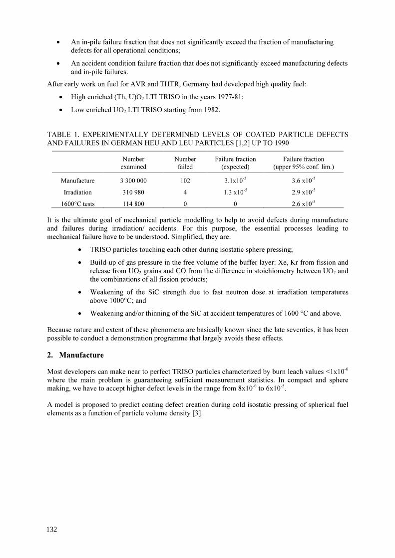
• An in-pile failure fraction that does not significantly exceed the fraction of manufacturing defects for all operational conditions;
• An accident condition failure fraction that does not significantly exceed manufacturing defects and in-pile failures.
After early work on fuel for AVR and THTR, Germany had developed high quality fuel: • High enriched (Th, U)O2 LTI TRISO in the years 1977-81; • Low enriched UO2 LTI TRISO starting from 1982.
TABLE 1. EXPERIMENTALLY DETERMINED LEVELS OF COATED PARTICLE DEFECTS AND FAILURES IN GERMAN HEU AND LEU PARTICLES [1,2] UP TO 1990
Number examined
Number failed
Failure fraction (expected)
Failure fraction (upper 95% conf. lim.)
Manufacture 3 300 000 102 3.1x10⁻⁵ 3.6 x10⁻⁵ Irradiation 310 980 4 1.3 x10⁻⁵ 2.9 x10⁻⁵ 1600°C tests 114 800 0 0 2.6 x10⁻⁵
It is the ultimate goal of mechanical particle modelling to help to avoid defects during manufacture and failures during irradiation/ accidents. For this purpose, the essential processes leading to mechanical failure have to be understood. Simplified, they are:
• TRISO particles touching each other during isostatic sphere pressing; • Build-up of gas pressure in the free volume of the buffer layer: Xe, Kr from fission and
release from UO2 grains and CO from the difference in stoichiometry between UO2 and the combinations of all fission products;
• Weakening of the SiC strength due to fast neutron dose at irradiation temperatures above 1000°C; and
• Weakening and/or thinning of the SiC at accident temperatures of 1600 °C and above. Because nature and extent of these phenomena are basically known since the late seventies, it has been possible to conduct a demonstration programme that largely avoids these effects. 2. Manufacture Most developers can make near to perfect TRISO particles characterized by burn leach values <1x10⁻⁶ where the main problem is guaranteeing sufficient measurement statistics. In compact and sphere making, we have to accept higher defect levels in the range from 8x10⁻⁶ to 6x10⁻⁵. A model is proposed to predict coating defect creation during cold isostatic pressing of spherical fuel elements as a function of particle volume density [3].
132
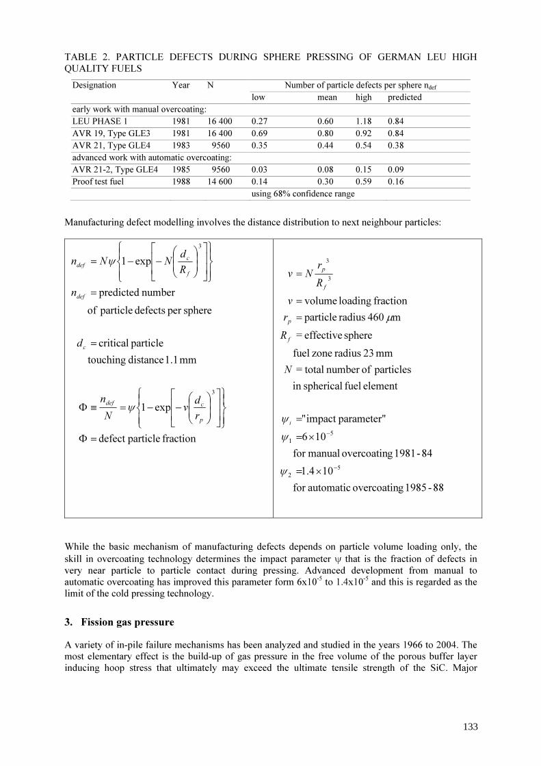
TABLE 2. PARTICLE DEFECTS DURING SPHERE PRESSING OF GERMAN LEU HIGH QUALITY FUELS
Number of particle defects per sphere ndef Designation Year N low mean high predicted
early work with manual overcoating: LEU PHASE 1 1981 16 400 0.27 0.60 1.18 0.84 AVR 19, Type GLE3 1981 16 400 0.69 0.80 0.92 0.84 AVR 21, Type GLE4 1983 9560 0.35 0.44 0.54 0.38 advanced work with automatic overcoating: AVR 21-2, Type GLE4 1985 9560 0.03 0.08 0.15 0.09 Proof test fuel 1988 14 600 0.14 0.30 0.59 0.16 using 68% confidence range
Manufacturing defect modelling involves the distance distribution to next neighbour particles:
fraction particledefect
exp1
mm 1.1 distance touching particle critical
sphereper defects particle ofnumber predicted
exp1
3
3
=Φ
−−=≡Φ
=
=
−−=
p
cdef
c
def
f
cdef
rdv
Nn
d
n
RdNNn
ψ
ψ
88-1985 govercoatin automaticfor 104.1
84-1981 govercoatin manualfor 106parameter"impact "
element fuel sphericalin particles ofnumber total=
mm 23 radius zone fuel sphere effective =
m 460 radius particle fraction loading volume
52
51
3
3
−
−
×=
×=
=
=
=
=
ψ
ψψ
µ
i
f
p
f
p
N
Rrv
Rr
Nv
While the basic mechanism of manufacturing defects depends on particle volume loading only, the skill in overcoating technology determines the impact parameter ψ that is the fraction of defects in very near particle to particle contact during pressing. Advanced development from manual to automatic overcoating has improved this parameter form 6x10⁻⁵ to 1.4x10⁻⁵ and this is regarded as the limit of the cold pressing technology.
3. Fission gas pressure A variety of in-pile failure mechanisms has been analyzed and studied in the years 1966 to 2004. The most elementary effect is the build-up of gas pressure in the free volume of the porous buffer layer inducing hoop stress that ultimately may exceed the ultimate tensile strength of the SiC. Major
133
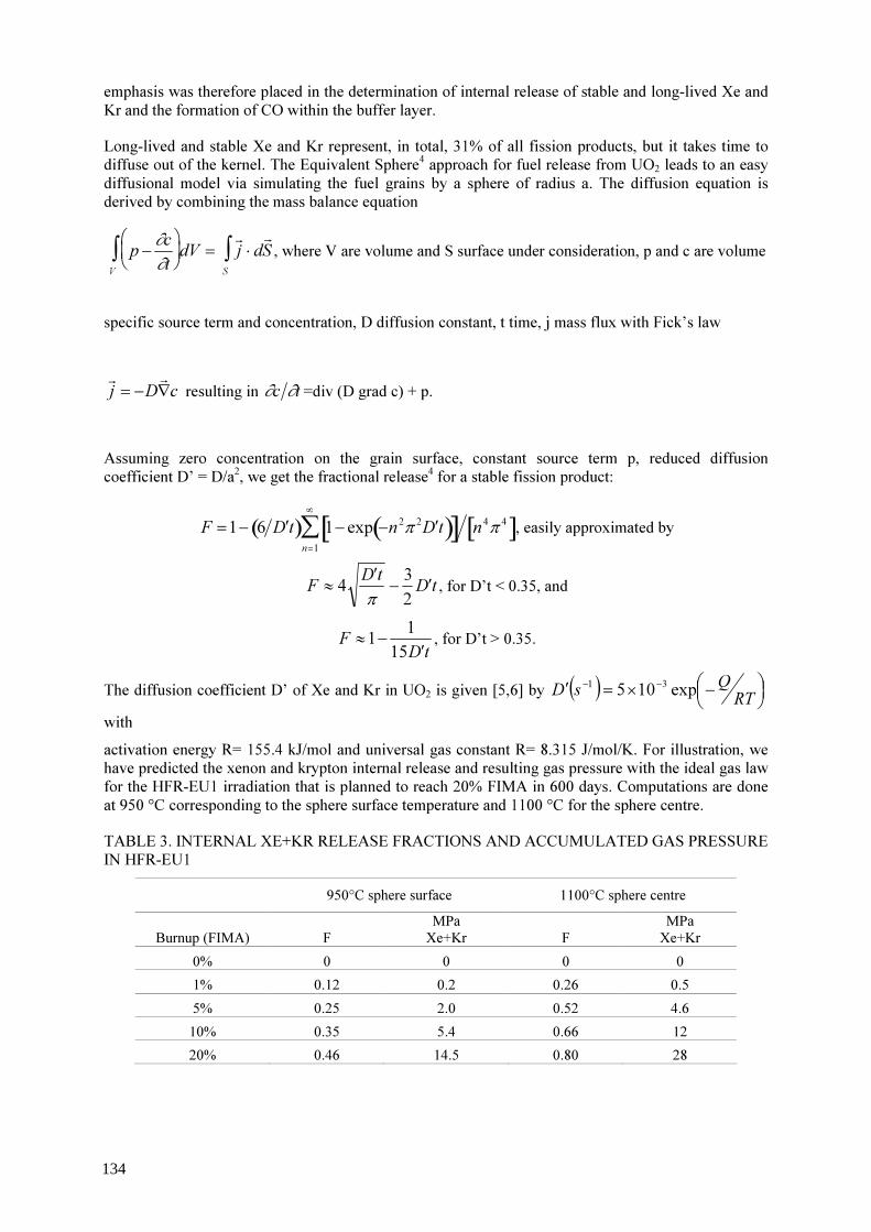
emphasis was therefore placed in the determination of internal release of stable and long-lived Xe and Kr and the formation of CO within the buffer layer. Long-lived and stable Xe and Kr represent, in total, 31% of all fission products, but it takes time to diffuse out of the kernel. The Equivalent Sphere4 approach for fuel release from UO2 leads to an easy diffusional model via simulating the fuel grains by a sphere of radius a. The diffusion equation is derived by combining the mass balance equation
p − ∂c∂t
V∫ dV = r j ⋅ dr S
S∫ , where V are volume and S surface under consideration, p and c are volume
specific source term and concentration, D diffusion constant, t time, j mass flux with Fick’s law
cDj ∇−=rr resulting in ∂c ∂t =div (D grad c) + p.
Assuming zero concentration on the grain surface, constant source term p, reduced diffusion coefficient D’ = D/a2, we get the fractional release4 for a stable fission product:
F =1− 6 ′ D t( ) 1− exp −n 2π 2 ′ D t( )[ ] n 4π 4[ ]n=1
∞∑ , easily approximated by
F ≈ 4 ′ D tπ
− 32
′ D t , for D’t < 0.35, and
F ≈1− 115 ′ D t
, for D’t > 0.35.
The diffusion coefficient D’ of Xe and Kr in UO2 is given [5,6] by ( )
−×=′ −−
RTQsD exp105 31
with activation energy R= 155.4 kJ/mol and universal gas constant R= 8.315 J/mol/K. For illustration, we have predicted the xenon and krypton internal release and resulting gas pressure with the ideal gas law for the HFR-EU1 irradiation that is planned to reach 20% FIMA in 600 days. Computations are done at 950 °C corresponding to the sphere surface temperature and 1100 °C for the sphere centre. TABLE 3. INTERNAL XE+KR RELEASE FRACTIONS AND ACCUMULATED GAS PRESSURE IN HFR-EU1
950°C sphere surface 1100°C sphere centre
Burnup (FIMA) F MPa Xe+Kr F
MPa Xe+Kr
0% 0 0 0 0 1% 0.12 0.2 0.26 0.5 5% 0.25 2.0 0.52 4.6 10% 0.35 5.4 0.66 12 20% 0.46 14.5 0.80 28
134
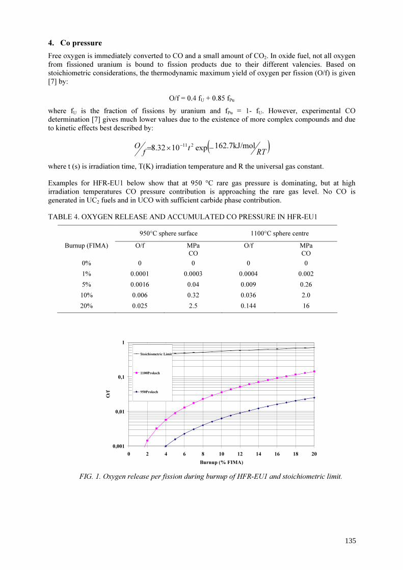
4. Co pressure Free oxygen is immediately converted to CO and a small amount of CO2. In oxide fuel, not all oxygen from fissioned uranium is bound to fission products due to their different valencies. Based on stoichiometric considerations, the thermodynamic maximum yield of oxygen per fission (O/f) is given
[7] by: O/f = 0.4 fU + 0.85 fPu
where fU is the fraction of fissions by uranium and fPu = 1- fU. However, experimental CO determination [7] gives much lower values due to the existence of more complex compounds and due to kinetic effects best described by:
( )RTtfO kJ/mol7.162exp1032.8 211 −×= −
where t (s) is irradiation time, T(K) irradiation temperature and R the universal gas constant. Examples for HFR-EU1 below show that at 950 °C rare gas pressure is dominating, but at high irradiation temperatures CO pressure contribution is approaching the rare gas level. No CO is generated in UC2 fuels and in UCO with sufficient carbide phase contribution. TABLE 4. OXYGEN RELEASE AND ACCUMULATED CO PRESSURE IN HFR-EU1
950°C sphere surface 1100°C sphere centre Burnup (FIMA) O/f MPa
CO O/f MPa
CO 0% 0 0 0 0 1% 0.0001 0.0003 0.0004 0.002 5% 0.0016 0.04 0.009 0.26 10% 0.006 0.32 0.036 2.0 20% 0.025 2.5 0.144 16
0,001
0,01
0,1
1
0 2 4 6 8 10 12 14 16 18 20Burnup (% FIMA)
O/f
Stoichiometric Limit
1100Proksch
950Proksch
FIG. 1. Oxygen release per fission during burnup of HFR-EU1 and stoichiometric limit.
135

5. SiC strength As is typical for brittle ceramic materials, the SiC strength distribution follows a Weibull statistic with
F(S) = 1- exp { - ln 2 (S/UTS)m} representing the cumulative probability for strength values between 0 and S. UTS is the median strength, and m is the Weibull modulus. We assume the measured values for particle batch EO 1607 to be representative for modern German TRISO particles and have used these values in the HFR-EU1 predictions. Both UTS and m are diminishing during irradiation, particularly at temperatures > 1000 °C. This is described by the correlations8:
UTSirr = max 834MPa 1− ΓΓs
, 196MPa
, whereby Γs = 3.6e−QRT
mirr = max 8.02 1− ΓΓm
, 2
, whereby Γs = 2.5e−QRT
T (K) is irradiation temperature, Γ (1025m-2) is fast fluence > 0.1 MeV and Q = 12 44 kJ/mol is the activation energy of the strength deterioration.
FIG. 2. Cumulative stress survival probability [9] of EO1607 SiC rings measured by the Juelich brittle ring test [10]. Strength and Weibull modulus decrease after irradiation to 1.8x1025m-2 EDN at 1 165 °C in test HFR-GM1. 6. Particle failure prediction Failure of a layer is reached when the induced stress σ t
σ t =r2pt
136

exceeds the strength of the material. Here, p is the total internal pressure, r and t are radius and thickness of the layer. We assume the SiC layer in the TRISO particle as the essential load bearing element of the coating. This approach is, however, too simple. One simple way to account for pre-stressing the SiC by inner and outer PyC is a thin shell formula below:
( ) ( )
−+
+
−=oPyCSiC
tiPyC k
grt
rt
kg
rtp
νσ
ν 112 &&
p is internal pressure, t and r are thickness and mean radius of the respective layer. Further: creep.in ratioPoisson the and constant, creep theis rate, shrinkage inducedneutron theis νkg&
Eventually this approach has led to a much more sophisticated level in the STRESS code, in CONVOL and more recent formulations [11-13,16,18,19]. Still sticking to the emphasis on a single thin shell in the PANAMA approach [6,17], we have concentrated on details of irradiation behaviour of gas release and silicon carbide strength. The “soap bubble formula” has been combined with the SiC strength statistics into the failure function Φ:
−−=Φ
m
medtrpσ22lnexp1 , where
p is internal pressure calculated from the ideal gas law, t and r are thickness and mean radius of SiC. Then: σmed is median SiC strength. Predictions for the 20% FIMA test HFR-EU1 are shown below. PANAMA has also been used for HTTR and PBMR (various designs) normal operation predictions, but we are aware that neglecting the positive influence of inner and outer PyCs in the full formulation might be overly pessimistic. However, because we conservatively assume that thermal relaxation of PyC might make pre-stressing the SiC ineffective during unrestrained core heatup, we used the simpler PANAMA code to reproduce particle failures as observed in the more than forty KUEFA core heatup simulation heating tests. These were done for the AVR fuel elements heated to between 1 600 and 2500 °C, irradiation tests FRJ2-K13, K15 (prediction only), R2-K13, HFR-K3, P4, SL-P1 and for predictions in reactor systems HTR 100, MODUL, FAPIG-HTR, MHTGR and PBMR. In case of high fluence irradiation like HFR-P4, PANAMA tends to overpredict failure. We will review this in the next years in the IAEA CRP6 co-operation15 by benchmarking of failure codes world-wide. Scoping calculations with PANAMA have been useful for exploring the operating range of the HFR-EU1 irradiation experiment that will be operated to 20% FIMA and a fluence of 6x1025m-2 (E>0.1 MeV). For more refined calculations, it will be necessary to restore the CONVOL code from an un-maintained state 1986-2003 to explore further limits of coated particle fuel performance. If PANAMA is right, Fig. 3 shows first particles in HFR-EU1 to fail in the centre after 13% FIMA and at the surface at 19% FIMA. Since there are continuous R/B measurements planned, the test can be stopped before massive failure occurs. Figure 4 shows that at 20% FIMA, there is little margin for temperatures over 950 °C.
137

1 E-91 E-81 E-71 E-61 E-51 E-41 E-31 E-21 E-11 E+0
0% 5% 10% 15% 20% 25% 30%Burnup (%FIMA)
Failu
re fr
actio
n
T=1100°C
T=950°C
FIG. 3. PANAMA particle failure prediction HFR-EU1: failure on one particle after 13% FIMA at 1100 °C and after 19% FIMA at 950 °C.
1 E-81 E-71 E-61 E-51 E-41 E-31 E-21 E-11 E+0
600 800 1000 1200 1400 1600Irradiation temperature (°C)
failed
parti
cle fr
actio
n
FIG. 4. PANAMA particle failure prediction HFR-EU1 at 20% FIMA for 600-1400°C.
The combination of all effects of shrinkage, creep, thermal expansion in a 3d tensor formulation has been realized in the 1968 STRESS code amply described in the literature [10,11,16]. It was further developed and streamlined in a co-operation between Harwell, Dragon and Juelich 1971-75 and successfully employed to reproduce particle failure in the LE Charge III Centre Rod series by assuming a 300 MPa SiC median strength with Weibull modulus 7 and a PyC creep strain limit of 10%.
138
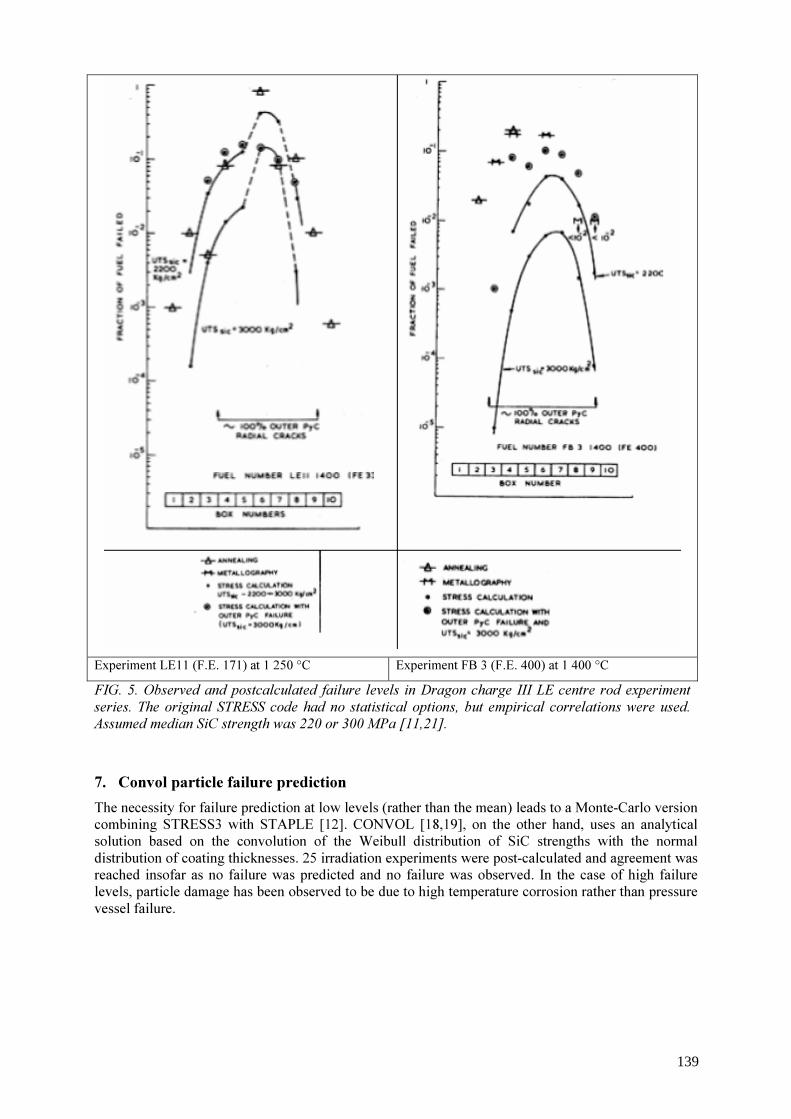
Experiment LE11 (F.E. 171) at 1 250 °C Experiment FB 3 (F.E. 400) at 1 400 °C FIG. 5. Observed and postcalculated failure levels in Dragon charge III LE centre rod experiment series. The original STRESS code had no statistical options, but empirical correlations were used. Assumed median SiC strength was 220 or 300 MPa [11,21]. 7. Convol particle failure prediction The necessity for failure prediction at low levels (rather than the mean) leads to a Monte-Carlo version combining STRESS3 with STAPLE [12]. CONVOL [18,19], on the other hand, uses an analytical solution based on the convolution of the Weibull distribution of SiC strengths with the normal distribution of coating thicknesses. 25 irradiation experiments were post-calculated and agreement was reached insofar as no failure was predicted and no failure was observed. In the case of high failure levels, particle damage has been observed to be due to high temperature corrosion rather than pressure vessel failure.
139

TABLE 5. CONVOL PREDICTIONS [8[ FOR HEU TRISO PARTICLE FAILURE
8. Outlook Simple pressure versus strength estimates are not good enough for coated particle design and lifetime predictions. Beyond that, PANAMA including SiC Weibull statistics incorporates the simplest conceivable modelling approach reproducing in-pile and accident performance. Code validation and verification has gone further than most other codes, but PANAMA also has severe limitations. CONVOL and the STRESS3/ STAPLE combo are much more sophisticated. For CONVOL, however, a new round of verification and validation is required, since the code had been unmaintained for two decades. The objects of code validation are well conducted and documented irradiation experiments. Figure 6 shows an overview over German irradiation testing with high quality TRISO fuels. While results from Material Test Reactors are detailed, these tests are limited in number: phase 1 refers to LEU fuels made in Germany 1981-83, phase 2 to 1985-88. Large numbers of fuel elements have been tested in AVR, but here the individual irradiation history is not well known. Burnup is measured and fluence/ irradiation times can be derived reliably when knowledge on AVR operation is available. In-pile gas release from a single sphere is unknown except that, since the introduction of clean HEU TRISO and even cleaner LEU TRISO, short-lived gas release was continuously coming down. The knowledge of the necessary input data for all available models is, however, so limited that prediction of particle failure significantly beyond the experimental envelope is impossible at the present stage and the best we can do, is to go through all documented experimental material and plan new tests, if required. Other than pressure vessel failure, there are many ways a coated particle can fail: starting with manufacturing weaknesses, extreme irradiation conditions leading to amoebas and fission product attack to unusual events (core heatup, water ingress, air ingress). These have not been dealt with here. To answer the original question: we can predict particle failure when fuel is well characterized and is operated under conditions that have been experienced before and where the necessary data are
Irradiation Irradiation Irradiation IrradiationTest temp. (°C) Predicted Measured Test temp. (°C) Predicted Measured
FRJ2-P23/1 1067 2.3E-14 < 2 E-4 FRJ2-K11/3 1050 3.7E-17 < 1 E-4FRJ2-P23/1 1200 4.0E-13 < 2 E-4 FRJ2-K11/3 1150 2.6E-16 < 1 E-4FRJ2-P23/2 1169 2.9E-13 < 2 E-4 FRJ2-K11/3 1250 2.1E-15 < 1 E-4FRJ2-P23/2 1200 4.1E-12 < 2 E-4 FRJ2-K11/4 1070 3.0E-17 < 1 E-4FRJ2-P23/3 1465 1.5E-11 < 2 E-4 FRJ2-K11/4 1170 2.3E-16 < 1 E-4FRJ2-P23/3 1550 6.5E-10 < 2 E-4 FRJ2-K11/4 1270 1.6E-15 < 1 E-4FRJ2-P23/4 1305 4.5E-13 < 2 E-4 LE12 1290 4.8E-01 2 E-2FRJ2-P23/4 1350 8.7E-12 < 2 E-4 LE12 1240 4.6E-01 3 E-2BR2-P22/1 1550 8.2E-02 1 E-2 R2-K12/1 1060 4.9E-12 < 1 E-4BR2-P22/1 1350 2.1E-02 1 E-2 R2-K12/2 1200 6.5E-08 < 1 E-4BR2-P22/2 1550 1.2E-01 1 E-1 R2-K12/2 1100 1.0E-09 < 1 E-4BR2-P23 1000 2.8E-12 7 E-4 R2-K12/2 1300 1.9E-06 < 1 E-4BR2-P23 1100 1.6E-09 7 E-4 R2-K13/1 1200 4.1E-07 < 8 E-5BR2-P23 1000 3.0E-11 7 E-4 R2-K13/1 1300 7.2E-06 2 E-4BR2-P23 1100 3.9E-09 7 E-4 R2-K13/4 1000 1.3E-11 2 E-4BR2-P25 1000 3.4E-09 1 E-3 DR-S4 1150 3.3E-02 2 E-4BR2-P25 1100 2.8E-07 1 E-3 hom. batch 1250 5.0E-01 2 E-4
DR-S4/1 1150 2.4E-02 2 E-4batch 249 1250 4.6E-01 2 E-4DR-S4/2 1150 4.5E-02 2 E-4batch 251 1250 5.2E-01 2 E-4
Failure fraction Failure fraction
140

available. However, for the presently interesting high burnup/ high temperature requirements, we can compare code predictions, but will have to let experiments decide the outcome.
FIG. 6. Burnup-temperature tuples from German high quality TRISO fuel irradiation testing to be used as base material for performance code validation (we are grateful to Johan H Venter of PBMR for providing part of this diagram).
REFERENCES [1] VERFONDERN, K., SCHENK, W., NABIELEK, H., “Passive safety characteristics of fuel
for a modular HTR and fuel performance modelling under accident conditions”, Nucl. Techn. 91 (1990), 235.
[2] NABIELEK, H., KUEHNLEIN, W., SCHENK, W., HEIT, W., CHRIST, A., RAGOSS, H., “Development of Advanced HTR Fuel Elements”, Nucl. Eng. Des. 121 (1990), 199.
[3] KASTEN, P.R., MCDUFFEE, J., TAYLOR, A., NABIELEK H., VERFONDERN K., Appendix H, “Distribution of coated particles in an HTR spherical fuel element” of: “Development of Correlations between Fuel Performance and Test Parameters in Modular HTGRs”, Forschungszentrum Juelich internal report ISR-IB-9/94 from September 1994
[4] NABIELEK, H., HICK, H., WAGNER-LOEFFLER, M., VOICE, E.H., “Performance limits of coated particle fuel. Part III: Fission product migration in HTR fuel”, Dragon report 828/III, June 1974.
[5] HOMAN, F.J., NABIELEK, H., YANG, L., “Low-enriched fuel performance review”, FZJ report Juel 1502 and GA report GA-A14759, August 1978.
[6] VERFONDERN, K. and NABIELEK, H., “PANAMA: Ein Rechenprogramm zur Vorhersage des Partikelbruchanteils von Triso Partikeln unter Stoerfallbedingungen”, Forschungs-zentrum Juelich report Juel-Spez-298, February 1985.
[7] PROKSCH, E., STRIGL, A., NABIELEK, H., “Production of carbon monoxide during
141

burn-up of UO2 kerneled HTR fuel particles”, J. Nucl. Mat. 107 (1982), 28. [8] BORNSCHEIN, R., CHRIST, A., HANSON, D.L., MUNCKE, G., MYERS, B.F.,
NABIELEK, H., QUADE, U., RAGOSS, H., VERFONDERN, K., “HTR-Brennstoffverhalten im Normalbetrieb und in Stoerfaellen”, FZJ internal report HBK-IB-09/84, December 1984 (unpublished).
[9] KOVACS, W.J., NABIELEK, H., “Status report on bench-mark stress calculations” GA document 906814, 3 June 1983 (unpublished).
[10] BONGARTZ, K., et al, “The brittle ring test: a method for measuring strength and Young’s modulus on coatings of HTR fuel particles”, J. Nucl. Mat. 62 (1976), 123.
[11] HICK, H., NABIELEK, H., HARRISON, T. A., BONGARTZ, K., MANCINI, G., MARTIN, D.G., “Performance limits of coated particle fuel. Part II: Mechanical failure of coated particles due to internal gas pressure and kernel swelling”, Dragon report 828/II, December 1973.
[12] MARTIN, D.G., “Some fundamental considerations pertaining to modelling the mechanical behaviour of Coated Particle Fuel during irradiation”, this Technical Meeting.
[13] MILLER, G.K., PETTI, D.A., VARACALLE, D.J., MAKI, J.T., “Statistical approach and benchmarking for modelling multi-dimensional behaviour in Triso coated fuel particles”, J. Nucl. Mat. 317 (2003), 69.
[14] MARTIN, D.G., NABIELEK, H., “A model to describe the failure of irradiated Triso coated fuel particles at high temperatures”, Harwell report AERE-R 10898, May 1983.
[15] PHELIP, M., KADARMETOV, I., PETTI, D., NABIELEK, H., VERFONDERN, K., ABRAM, T., “Triso particle performance code benchmarking activities performed under the IAEA 6th Coordinated Research Program on Advances in HTGR Fuel Technology”, this Technical Meeting.
[16] WALTHER, H., “Stress analysis in coated fuel particles: part I – theory and examples”, Dragon Project report 604. August 1968.
[17] APPENDIX C “The mathematical Basis of the PANAMA-I code for modelling pressure vessel failure of Triso coated particles under accident conditions” (Karl Verfondern) in: Renate Gontard and Heinz Nabielek “Performance evaluation of modern HTR Triso fuels”, FZJ internal report HTA-IB-05/90, July 1990 (unpublished).
[18] BONGARTZ, K., “Improvement of a method for predicting failure rates of coated particles during irradiation”, Nucl. Techn. 35 (1977), 379.
[19] BONGARTZ, K., “Status of the fuel stress and failure rate calculations at KFA”, FZJ report Juel-1686, November 1980.
[20] ABRAM, T., GUILLERMIER, P., NABIELEK, H., PELLETIER, M., MARTIN, D., “Selection of properties and models for the HTR coated particle”, European Commission HTR-F report, December 2003, (unpublished)
[21] GOOD, P.D., GILES, P.G.R., “The post-irradiation measurement of noble gas release from the Charge III LE UO2 Centre Rod experiments”, Dragon report 922, March 1975.
142

Some fundamental considerations pertaining to modelling the mechanical behaviour of coated fuel particles during irradiation
D.G. Martin NFC, Wantage, Oxon, United Kingdom
Abstract. A number of important features that are required in a computer code to model the irradiation performance of coated fuel particles during irradiation are identified. Amongst these are the following: (a) A suitable equation of state to calculate the internal gas pressure is necessary since the perfect gas law is inadequate. (b) An allowance for the presence of CO2 should be taken into account when calculating gas pressures. (c) The code should be able to model the whole life of a particle, from manufacture, followed by a complex irradiation history and then on to long term storage. (d) Kernel-coating mechanical interaction (KCMI) as a possible cause of particle failure must be taken into account. (e) Execution times must be sufficiently fast to enable statistical calculations, involving many computer runs, to be feasible. These features are illustrated in the modelling of a number of experiments using the computer program STRESS3 and the associated statistical code STAPLE. The modelling of two Japanese irradiation experiments illustrated (a) the need for a statistical code, and (b) to be able to model monotonic changes in temperature over the course of an irradiation, in order to reproduce the experimental observations. Pre-irradiation modelling of German fuel in the HFR-EU1 experiment demonstrated that KCMI is predicted to be the predominant failure mechanism, and that statistical variations in the burn-up at which failures occur are governed, almost entirely, by the variability in the buffer layer thickness. KCMI was also identified as a failure mechanism in the US NPR–1 irradiation, but only after the inner pyrocarbon (IPyC) layer had failed first. This was identified as being due to a rather subtle IPyC Poisson ratio effect. A modelling of the comprehensive Dragon project charge III centre rod experiment is reported. A reasonable correlation with experimental observations was obtained provided there was included the option that the outer pyrocarbon (OPyC) layer had failed first, due to interaction with the retaining meniscus bonded resin.
1. Introduction In order to model the irradiation performance of coated fuel particles, two criteria must be satisfied. Firstly, one must possess a computer code that models adequately those physical and mechanical processes that affect significantly the irradiation behaviour of particles. Secondly, the relevant physical and mechanical properties of the materials constituting the particles must be known. In this paper only the first of these two topics will be discussed. Material properties, especially those of the pyrocarbon (PyC) layers is a topic of considerable uncertainty, as has been discussed previously [1,2]. Because of these uncertainties, the modelling of irradiation experiments to investigate the performance of various particle designs possesses its limitations. Indeed, the cynic might argue that modelling is a waste of time because the modeller can always adjust the material property values within the limits of present day uncertainties to make the calculated results agree with experiment. However, this is an over pessimistic view of the present day situation. Provided one possesses a reasonably satisfactory computer code it can, despite these limitations, yield valuable information. For example, it can help identify (a) the various mechanisms promoting failure, (b) which of the various physical and mechanical properties are most significant, (c) what tolerances in particle design are permissible during manufacture, and (d) assist in planning irradiation experiments. In other words, modelling enables us to gain a better scientific understanding of the processes that are occurring during irradiation.
143

This paper is in two parts. In the first, some of the features that need to be incorporated into a fuel performance code, if it is to be satisfactory, are discussed. The second part describes the modelling of some irradiation experiments by way of illustrating the importance of some of these features. Given the uncertainty in the input data already noted, no great emphasis will be placed on how well calculation and experiment are in agreement. However it is worth noting that very nearly the same input data relating to material properties were used in modelling the irradiations from laboratories around the world that are described below. The modelling was performed using STRESS3 [3], a code which models stresses in individual particles, and STAPLE which calculates particle failure statistics by running STRESS3 many times. The STRESS1 code was first written in the Dragon Project [4], subsequently refined by Bongartz (KFA) and the present author, who then developed STAPLE [3]. While STRESS3 and STAPLE possess those desirable features of a fuel performance code that have been identified here, it is not claimed that in the future they will never require further refinements. For example, these codes assume that the properties of each layer are the same throughout its thickness. It is not impossible that under certain manufacturing procedures this assumption may prove to be untrue.
Fig.1: A Comparison between the Redlich-Kwong Equation of State (Lines) and Experimental Values (Points) for Xenon
020406080
100120140160180200
100 150 200 250 300 350 400 450 500 550 600Volume per Mole ×10-6 m3
Pres
sure
M
Pa 1408°C
1002°C
278°C
FIG. 1. A comparison between the Redlich-Kwong Equation of State (Lines) and experimental values (Points) for Xenon. 2. Some important features that are desirable in an advanced fuel performance code In Sections 2.1 and 2.2 matters concerned with the calculation of gas pressure are discussed. Section 2.3 describes in qualitative terms some other desirable features. 2.1. An equation of state Because it is known that failure of coatings will occur if the internal gas pressure exceeds some critical value, it is clearly important that an appropriate equation of state be employed to calculate pressures. Amongst the many equations of state which have been proposed, the one by Redlich and Kwong [5] appears to combine the advantages of both a simple formula and a high level of accuracy for the current application. Fig. 1 compares some experimental pressure-volume values for xenon, due to Harrison [6], at three temperatures, with the corresponding Redlich-Kwong isotherms. It is apparent
144

that agreement is excellent over the temperatures and pressures that are relevant to coated particle modelling. The Redlich-Kwong equation of state is:
P + aT 1/2V(V + b)
V − b( )= RT (1)
where P, V, T and R represent pressure, volume per mole, temperature and the universal gas constant respectively. a and b are constants whose values are obtained by noting that at the critical point
Fig.2: Correction of Fission Gas pressures, calculated assuming the Perfect Gas Law
0.2
0.4
0.6
0.8
1.0
1.2
1.4
1.6
1.8
0 20 40 60 80 100 120Pressure, assuming the Perfect Gas Law is valid MPa
Multip
lioca
tion F
actor
20°C100°C800°C1400°C
FIG. 2. Correction of fission gas pressures, calculated assuming the perfect gas law.
∂P∂V
T =
∂2P∂V 2
T
= 0 (2)
implying that
a = R2Tc
2.5
9ξ Pc, b = ξ RTc
3Pc (3), (4)
where Tc , Pc are the critical temperature and pressure and ξ = 21/3–1. In the case of a gas mixture mean values of a and b, ba and are required, given by
a = ζmam0.5m=1
µ
∑2
and b = ζmbmm=1
µ
∑ (5), (6)
where µ is the number of gas species comprising the mixture and ζm the fraction of gas molecules in the mixture that consist of species m.
145

Figure 2 illustrates the inadequacy in using the perfect gas law to calculate gas pressures within coated particles. The abscissa represents the gas pressure of a Xe-Kr fission gas mixture that would be calculated, knowing the temperature, the number of moles of gas present and the volume they can occupy, using the perfect gas law. Ordinate values show the factor by which this pressure needs to be multiplied in order to obtain the corresponding Redlich-Kwong equation of state value. Fig. 2 demonstrates that during irradiation gas pressure values could be underestimated by up to ~40% if the perfect gas law is used in the calculation.
Fig. 3: Effect of CO2 Production on Gas Pressure
0.5
0.6
0.7
0.8
0.9
1
0 20 40 60 80 100Po , Gas Pressure assuming all Oxygen combined as CO MPa
Actua
l Pres
sure
expre
ssed
as a
Fracti
on of
P o
0
0.2
0.4
0.6
0.8
1
f, Fra
ction
of R
eleas
ed O
xyge
n Co
mbine
d as C
O600°C800°C1000°C1200°C1400°C
FIG. 3. Effect of CO2 production on gas pressure.
This is mainly because it ignores the volume occupied by the gas molecules. By contrast, when irradiated particles are cooled to room or ambient temperatures, pressures could be overestimated by a factor of ~2 if the perfect gas law is employed. This is because these temperatures are close to the critical temperature, when the gas will be attaining more liquid-like properties. It also implies that stresses in the silicon carbide (SiC) layer during the long term storage of irradiated particles will be lower compared with those derived using the perfect gas law. 2.2. Gas pressure contributions due to CO and CO2
Let us assume that as a result of irradiation a hypothetical pressure PO of oxygen atoms is created in the voidage. In practice this oxygen will react virtually completely with carbon to produce equilibrium concentrations of CO and CO2 in accordance with the Boudouard reaction
C + CO2 ⇔ 2CO. (7) If f is the fraction of oxygen atoms that react to form CO, the partial pressures of CO and CO2 are given by
PCO = f PO (8)
OCO PfP )1(21
2−= (9)
so that the total pressure,
146

PCO + PCO2 =12 (1+ f )PO . (10)
The equilibrium constant, KP , defined as
KP =[PCO ]2PCO2
(11)
is equal to [7] exp 18.36 − 1.997 ×10⁴T
MPa to an accuracy of better 2.2%.
From equations (8)–(11) it follows that PCO + PCO2
PO=12+
KP2 + 8KPPO − KP
8PO. (12)
Figure 3 shows a plot of this fraction and also of f as a function of PO for a number of temperatures. It is apparent that in many situations a significant fraction of the oxygen reacts with carbon to form CO2 and that this will lower the additional pressure from the oxygen released during fission compared with the situation in which it reacted to produce only CO. Finally, from the point of view of establishing the composition of the gas, which will be required in the calculations described in Section 2.1, we note that if no moles of oxygen atoms are created by irradiation, then the number of moles of CO and CO2,
2 and COCO nn are given by:
PCOPO=nCO
nO=
KP2 + 8KPPO − KP
4PO (13)
and PCO2PO=nCO2
nO=12−
KP2 + 8KPPO − KP
8PO. (14)
2.3. Some other desirable features of a computer code In addition to being able to calculate gas pressures reasonably accurately, a few of the other desirable features that should be incorporated into an advance computer code are presented here. The need for them is illustrated in the modelling exercises reported in Section 3. An adequate model should be able to handle the history of a coated particle, from its manufacture, during irradiation, and finally throughout its long term storage in a repository. Amongst other things this implies that during irradiation changes in the neutron flux and temperature are capable of being modelled, for example as particles pass through and are then re-inserted into a pebble bed reactor, and also during shut-downs. This is not to say that simpler models have no use. For example, analytical models that assume constant neutron flux and temperature values enable stresses in the layers to be calculated readily by hand. Furthermore they enable a scientific understanding of how the various material properties influence these stresses [8]. The same is also true of simple models which calculate the stresses that are introduced due to a change in temperature [9]. Another feature which a coated particle performance code should be able to model is the possibility that particles may fail due to kernel-coating mechanical interaction (KCMI) [2], a mechanism which to date has received little attention. Failure by this means rather than because of a sufficient build-up of gas pressure may occur if the buffer layer possesses adequate voidage, or if the fraction of gas released
147

from the kernel is small as will occur at sufficiently low irradiation temperatures. It is well known that fuel kernels will swell during irradiation; as a result, once gaps between the kernel and IPyC layer have closed, this will enhance considerably stresses in the SiC layer due to its high (compared with PyC) elastic modulus. Failure of this layer will then occur at burn-up values only slightly in excess of that at which KCMI is initiated. Not many experimental irradiations appear to have been reported where failure of particles has been attributed to KCMI. The one clear case known to the author is an unpublished report by G.W. Horsley and P.E. Brown (Harwell Laboratory, 1971) relating to the irradiation of some gas cooled fast reactor particles to 11.7% FIMA burnup at around 925 °C. An obvious way of postponing the onset of KCMI is to increase the early in life gas gap between the kernel and IPyC layer by enhancing the thickness of the buffer, since the gap is caused by its shrinkage in the radial direction during irradiation. However, a sizeable gap containing low thermal conductivity fission gases will result in a significant temperature drop between the fuel and cladding. Bearing in mind that in practice the kernel is unlikely to remain in a perfectly symmetrical position within the particle, temperature variations around the periphery of the IPyC layer would then be expected, which could promote appreciable carbon transport (the amoeba effect). So clearly there must be a limit to how much the thickness of the buffer layer can be increased in order to avoid KCMI. Computer codes which calculate stresses in the layers of particles during the course of an irradiation are invaluable in determining the burn-up at which failure will occur. However, such calculations only refer to individual particles, whereas in practice one is interested in the fraction of a batch of particles that have failed as a function of burn-up. The most satisfactory way to calculate failure fractions is to run the code many times, varying for each run the particle specifications in accordance with the statistical variation of items such as the layer thicknesses. Because in practice 105
– 106 runs are required in order to obtain the relevant statistical information, it is clear that execution times of one’s code must be made as short as possible if this method of calculating particle failure statistics is to be viable. In the early days of modelling, given the computer processor speeds available at the time, such statistical calculations were only possible using simple codes. Alternatively, with a more refined code the problem was circumvented by adopting a convolution procedure in which stresses in the SiC layer were assumed to vary linearly with variations in each of the particle parameters [10]. Recently, in the case of a sophisticated code which employed finite element methods, certain approximations were introduced in order to obtain statistical results [11]. The value of possessing a code with the features discussed above is illustrated in Section 3, where the code STRESS3 [3] is employed to model a number of irradiation experiments. This code is also able to treat the anisotropy of any material property and to model the fracture and debonding of layers until, if so desired, all have failed. Because STRESS3 possesses fast execution times (e.g. one whole run takes about 0.01 sec. on a computer with an AMD Athlon 1.4GHz processor) statistical calculations involving many runs of STRESS3 are feasible. The code STAPLE [3] was developed to perform such calculations. 3. Some practical examples that illustrate a number of important factors in modelling Particle Endurance 3.1. HRB–22 irradiation [12] In this Japanese sponsored irradiation in the High Flux Isotope Reactor (HFIR) at Oak Ridge National Laboratory, 32 000 particles were irradiated up to a maximum burn-up of 7%. Four failures were observed, two each in the region of 2.5 and 6% respectively. STRESS3 calculations, using mean particle specifications, predicted that up to 7% burn-up the SiC layer was always under compression, implying that no failures would occur. This conclusion was in agreement with a previous calculation using a Japanese fuel performance code [13]. Even if both PyC layers were to fail very early in the irradiation, another STRESS3 run showed that tensile stresses at the end of life were extremely modest, and so unlikely to cause failure of the SiC layer.
148

These calculations employed mean particle dimensions and fracture stress values. However, when particle statistics are included in a STAPLE calculation two failures were predicted to occur over the burn-up range 6–7%. Therefore, to a first approximation, the third and fourth failures that were observed have been modelled successfully, but not the first two, which tentatively may be attributed to these particles being defective. The significant feature of this modelling exercise is it illustrates the importance of possessing a fuel performance code which can handle statistical variations within a batch of particles. A code which only calculates stresses in the layers of particles during the course of an irradiation is not very helpful in predicting failure fractions, especially at low values, of a batch of particles. Nevertheless, such a code can be useful in providing insight into the various factors affecting particle endurance. To give a specific example, it was through STRESS3 runs that in other irradiations, such as in some reported below, failures were identified to have been caused by KCMI. 3.2. 91F–1A irradiation [12] This irradiation in the Japanese materials test reactor comprised two capsules, upper and lower, each containing 4400 particles.
Fig.4: Stresses in the SiC Layer during Irradiation.
-300
-200
-100
0
100
200
300
400
500
0 2 4 6 8 10 12 14 16 18 20 22 24Burn-up %
Stre
sses
MPa
FIG. 4. Stresses in the SiC layer during irradiation. The upper capsule was irradiated at 1300 °C to a burn-up of 8%, by which time two failures were observed. Modelling of this irradiation produced results that were rather similar to those discussed above relating to the HRB–22 irradiation. It predicted two failures, in keeping with the experimental observations. Although the lower capsule experienced a higher rating compared with that of the upper capsule, so that a burn-up of 9.5 % was achieved, no failures were observed. It was speculated that this was because of the irradiation temperature history. During the first half of the irradiation particles were irradiated at 1250 °C. However at this point, due to a malfunction of the temperature controller, the temperature decreased monotonically with time, falling to 820 °C by the end of the irradiation. A STAPLE run was able to support this suggestion because, up to 9.5% burn-up no failures were predicted.
149
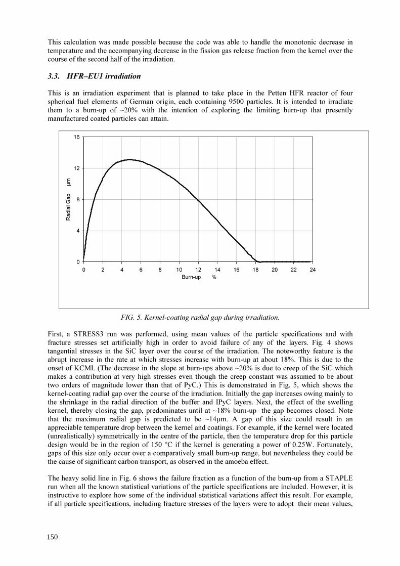
This calculation was made possible because the code was able to handle the monotonic decrease in temperature and the accompanying decrease in the fission gas release fraction from the kernel over the course of the second half of the irradiation. 3.3. HFR–EU1 irradiation This is an irradiation experiment that is planned to take place in the Petten HFR reactor of four spherical fuel elements of German origin, each containing 9500 particles. It is intended to irradiate them to a burn-up of ~20% with the intention of exploring the limiting burn-up that presently manufactured coated particles can attain.
Fig.5: Kernel-Coating Radial Gap During Irradiation.
0
4
8
12
16
0 2 4 6 8 10 12 14 16 18 20 22 24Burn-up %
Radia
l Gap
µm
FIG. 5. Kernel-coating radial gap during irradiation. First, a STRESS3 run was performed, using mean values of the particle specifications and with fracture stresses set artificially high in order to avoid failure of any of the layers. Fig. 4 shows tangential stresses in the SiC layer over the course of the irradiation. The noteworthy feature is the abrupt increase in the rate at which stresses increase with burn-up at about 18%. This is due to the onset of KCMI. (The decrease in the slope at burn-ups above ~20% is due to creep of the SiC which makes a contribution at very high stresses even though the creep constant was assumed to be about two orders of magnitude lower than that of PyC.) This is demonstrated in Fig. 5, which shows the kernel-coating radial gap over the course of the irradiation. Initially the gap increases owing mainly to the shrinkage in the radial direction of the buffer and IPyC layers. Next, the effect of the swelling kernel, thereby closing the gap, predominates until at ~18% burn-up the gap becomes closed. Note that the maximum radial gap is predicted to be ~14µm. A gap of this size could result in an appreciable temperature drop between the kernel and coatings. For example, if the kernel were located (unrealistically) symmetrically in the centre of the particle, then the temperature drop for this particle design would be in the region of 150 °C if the kernel is generating a power of 0.25W. Fortunately, gaps of this size only occur over a comparatively small burn-up range, but nevertheless they could be the cause of significant carbon transport, as observed in the amoeba effect. The heavy solid line in Fig. 6 shows the failure fraction as a function of the burn-up from a STAPLE run when all the known statistical variations of the particle specifications are included. However, it is instructive to explore how some of the individual statistical variations affect this result. For example, if all particle specifications, including fracture stresses of the layers were to adopt their mean values,
150
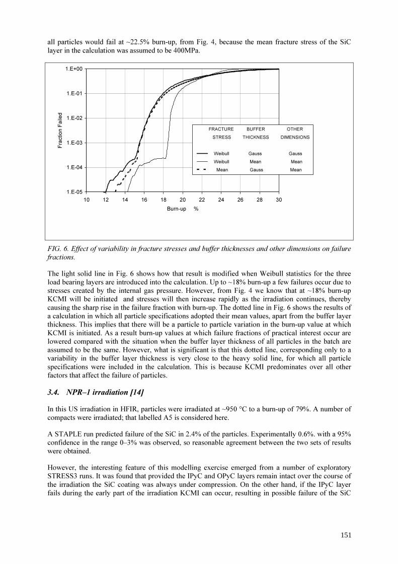
all particles would fail at ~22.5% burn-up, from Fig. 4, because the mean fracture stress of the SiC layer in the calculation was assumed to be 400MPa.
Fig. 6: Effect of Variability in Fracture Stresses and Buffer Thicknesses and other Dimensions on Failure Fractions.
1.E-05
1.E-04
1.E-03
1.E-02
1.E-01
1.E+00
10 12 14 16 18 20 22 24 26 28 30Burn-up %
Fracti
on Fa
iled
FRACTURE BUFFER OTHER STRESS THICKNESS DIMENSIONS
Weibull Gauss Gauss Weibull Mean Mean Mean Gauss Mean
FIG. 6. Effect of variability in fracture stresses and buffer thicknesses and other dimensions on failure fractions. The light solid line in Fig. 6 shows how that result is modified when Weibull statistics for the three load bearing layers are introduced into the calculation. Up to ~18% burn-up a few failures occur due to stresses created by the internal gas pressure. However, from Fig. 4 we know that at ~18% burn-up KCMI will be initiated and stresses will then increase rapidly as the irradiation continues, thereby causing the sharp rise in the failure fraction with burn-up. The dotted line in Fig. 6 shows the results of a calculation in which all particle specifications adopted their mean values, apart from the buffer layer thickness. This implies that there will be a particle to particle variation in the burn-up value at which KCMI is initiated. As a result burn-up values at which failure fractions of practical interest occur are lowered compared with the situation when the buffer layer thickness of all particles in the batch are assumed to be the same. However, what is significant is that this dotted line, corresponding only to a variability in the buffer layer thickness is very close to the heavy solid line, for which all particle specifications were included in the calculation. This is because KCMI predominates over all other factors that affect the failure of particles. 3.4. NPR–1 irradiation [14] In this US irradiation in HFIR, particles were irradiated at ~950 °C to a burn-up of 79%. A number of compacts were irradiated; that labelled A5 is considered here. A STAPLE run predicted failure of the SiC in 2.4% of the particles. Experimentally 0.6%. with a 95% confidence in the range 0–3% was observed, so reasonable agreement between the two sets of results were obtained. However, the interesting feature of this modelling exercise emerged from a number of exploratory STRESS3 runs. It was found that provided the IPyC and OPyC layers remain intact over the course of the irradiation the SiC coating was always under compression. On the other hand, if the IPyC layer fails during the early part of the irradiation KCMI can occur, resulting in possible failure of the SiC
151

layer. Further STAPLE exploratory runs indeed demonstrated that the predicted failures referred to above occurred by KCMI. The explanation why KCMI occurs when the IPyC has failed but not when it is intact is due to Poisson ratio dimensional changes in the latter case. At appreciable neutron doses a failed, unrestrained, IPyC layer will expand radially, thereby contributing to the closure of the kernel-coating gap. By contrast, an intact IPyC will be highly stressed in the tangential direction as it creeps in order to nullify the shrinkage that a corresponding unrestrained layer would undergo. From Poisson ratio considerations this will result in a shrinkage in the radial direction, thereby contributing to a delay in the burn-up value at which KCMI will be initiated. It is of interest to note that workers at Idaho have attributed these SiC failures to a different mechanism [15]. It, too, required that the IPyC layer should fail first. However SiC failures were attributed to the cracked, still partially bonded, IPyC layer enhancing stresses in the SiC. By contrast, STRESS3 assumes that when an IPyC layer fails it is simultaneously de-bonded from the SiC – in keeping, to the author’s knowledge, of the PIE of European manufactured fuel. However, irrespective of whether or not the failure mechanism proposed here is the correct one to describe the modelling of this irradiation, it is clearly a possible one by which, in the case of some irradiations, the SiC layer could undergo fracture. 3.5. Charge III centre rod experiment [16]
This irradiation in the Dragon reactor was a realistic demonstration of particle performance under power reactor conditions. Eight particle designs were irradiated at two temperatures, namely 1250 and 1400 °C. For each of these 16 combinations, several batches of 104 particles were irradiated at a number of burn-up values, up to 12%. Particles in each batch were held in position in their containing box by means of resin. to which they were meniscus bonded. At the end of the irradiation, PIE on a number of boxes was performed to determine the failure fractions. Results for two of the designs on which most PIE had been performed, LE 10 and FB 3, are shown as data points in Figs. 7 and 8.
FIG. 7. Modelling particle design LE 10. The solid lines in Figs. 7 and 8 are the results of STAPLE calculations, assuming an irradiation temperature of 1300 °C. It is evident that many of the experimental results lie above these lines.
152

STAPLE calculations were repeated, but now with the OPyC layer made to fail, to produce the dotted lines in Figs.7 and 8. It is apparent that many of the experimental results lie between the two lines. One can advance plausible arguments to justify the supposition that OPyC layers may fail during the irradiation. For example, failure of OPyC layers deposited from methane have been reported in the past [17]. Again, during the early stages of the irradiation, the resin holding the particles in position is expected to undergo large dimensional changes, which could cause such failures. If only a fraction of the OPyC layers were to have failed, then the appropriate failure line should lie somewhere between the two shown in each of Figs. 7 and 8. The modelling of this experiment has demonstrated the usefulness of possessing a code which can handle an irradiation that continues after a layer (or layers) have failed.
FIG. 8. Modelling particle design FB 3.
4. Concluding remarks It is highly desirable for there to be a close collaboration between experimentalists and modellers in the development of fuel that will perform to the desired specifications. This is because, for example (a) both experimentalists and modellers are able to identify failure mechanisms, (b) Experimental work can point to inadequacies in a fuel performance code, thereby leading to its improvement, (c) Modelling can greatly assist in the experimental work, both concerning the particle design and the irradiation conditions to aim for; in addition what PIE should be undertaken. Probably the biggest limitation in modelling studies lies in inadequacies in the available input data. This is especially the case with regard to the properties of the PyC and buffer layers. But despite these limitations, an advanced model such as STRESS3/ STAPLE is able to provide valuable insights into the underlying mechanisms that affect particle endurance, as has been illustrated in Section 3. However this is not to claim that any of today’s advanced codes will not require further refinement in the future, in the light of subsequent experimental work.
153
ACKNOWLEDGEMENTS The work reported here was funded by British Nuclear Fuels plc, Idaho National Engineering and Environmental Laboratory and the Japan Atomic Energy Research Institute, to whom grateful acknowledgement is made.
REFERENCES [1] INTERNATIONAL ATOMIC ENERGY AGENCY, Irradiation damage in graphite due to
fast neutrons in fission and fusion systems, IAEA–TECDOC–1154, (2000) pp. 135–158. [2] MARTIN, D.G., Considerations pertaining to the achievement of high burn-ups in HTR
fuel, Nucl. Eng. Design, 213 (2002) 241–258. [3] MARTIN, D.G., The Mathematical Basis of STRESS3 and STAPLE, Unpublished Report
(2003). [4] WALTHER, H., On mathematical models for calculating the mechanical behaviour of
coated fuel particles, Nucl. Eng. Design, 18 (1972) pp. 11–39 [5] REDLICH, O., KWONG J.N.S., On the Thermodynamics of Solutions- An equation of
state: Fugacities of gaseous solutions, Chem. Rev. 44 (1949) 233–244. [6] HARRISON, J.W., An extrapolated equation of state for xenon for use in fuel swelling
calculations, J. Nucl. Mater., 31 (1969) pp. 99–106. [7] KUBASCHEWSKI, O., EVANS, E. LI., ALCOCK, C. B, Metallurgical Thermochemistry,
4th Edition, Pergamon, Oxford, (1967). [8] MARTIN, D.G., An analytical method of calculating, to a reasonable accuracy, stresses in
the coatings of htr fuel particles, J. Nucl. Mater., 48 (1973) pp. 35–46. [9] MARTIN, D.G., An analysis of stresses created in the layers of coated fuel particles by
temperature change, 3rd Int. Conf. on Structural Mechanics in Reactor Technology, London, UK. Paper C1/4 (1975).
[10] MARTIN, D.G., Some calculations of the failure statistics. of coated fuel particles, Nucl. Tech., 42 (1979) pp. 304–311.
[11] MILLER, G.K., PETTI, D.A., VARACALLE, D.J., MAKI, J.T., Statistical approach and benchmarking for modeling of multi-dimensional behavior in TRISO-coated fuel particles, J. Nucl. Mater., 317 (2003) pp. 69–82.
[12] MARTIN, D.G., SAWA, K., UETA, S., SUMITA, J., A Study of fuel failure behavior in high burnup HTGR fuel; Analysis by STRESS3 and STAPLE codes, JAERI–Research 2001–033, May 2001.
[13] SAWA, K., MINATO. K., An Investigation of Irradiation Performance of High Burnup HTGR Fuel, J. Nucl. Sci. Tech., 36 (1999) pp. 781–791.
[14] MARTIN, D.G., Appendix C of INEEL FY 2002 Annual Report INEEL/EXT–02–01545 (2002).
[15] MILLER, G.K., PETTI, D.A., VARACALLE, D.J., MAKI, J.T., Consideration of the effects on fuel particle behavior from shrinkage cracks in the inner pyrocarbon layer, J. Nucl. Mater., 295 (2001) pp. 205–212.
[16] HICK, H., NABIELEK, H., HARRISON, T.A., DP Report 828 Part II (1973). [17] SAYERS, J.B., HORSLEY, G.W., MARTIN, D.G., ROSE, K.S.B., WILLIAMS, J.,
SAWBRIDGE, P.T., HORNER, P., SIMPSON, K.A., Nuclear Fuel Performance. Proc. Int Conf., London, B.N.E.S. (1973) pp. 32.1–32.6.
154
Fuel chemistry and co formation in gas cooled reactor fuel
U. Colak a, O.Ö. Gülol b a
b
Hacettepe University, Nuclear Engineering Department Ankara, Turkey
Turkish Atomic Energy Authority, Nuclear Safety Department Ankara, Turkey
Abstract. High temperature gas cooled reactors are considered as a promising candidate for the next generation nuclear power plants. They offer rather high safety standards together with economical competitiveness with respect to other conventional energy sources. High temperature process heat utilization is also another attractive feature of these reactors especially for hydrogen production. Coated fuel particles (CP) used as dispersed in graphite matrix is typical arrangement of fuel in these reactors. Coated fuel particles are the primary barrier against the release of radioactive fission products. Therefore, the design of particles is an essential part of safety. One potential failure mode is excessive internal pressure buildup exceeding mechanical strength of SiC layer. In this study, typical internal gas pressures for coated particles are calculated as a function of temperature and burnup. The fission product concentrations as a function of burnup are calculated using the well known depletion code ORIGEN-S. The amount of pressure buildup is estimated using two components; noble gas contribution from fission products and CO contribution. CO formation is attributed to migration of free oxygen released upon fission and not bound with any fission product yet to buffer layer. The results of this study are assessed in terms of coated fuel particle integrity.
1. Introduction High temperature gas cooled reactors are among the possible candidates for the next generation nuclear power plants. This is mainly due to high safety standards, possibility for the use in high temperature process heat applications, better proliferation resistance, attractive waste characteristics, and attractive cost considerations. Modern gas cooled reactors are considered in two different categories. Reactors with prismatic fuel are included in the first group. Spherical fuel elements are employed in the second group. However, the basic fuel structure in both cases is the coated fuel particle. Particles are embedded into graphite matrix to form either spherical or prismatic fuel elements. Particles are designed such that radioactive fission products are contained within the particle during the operation of the reactor. In order to ensure this, coated particles (CPs) are designed and manufactured to operate with very low failure probabilities and fission product release rates. Fuel kernel is surrounded by a low density graphite buffer layer to accommodate fission product gases. It is covered with a pyrolitic carbon layer (PyC) called inner pyrolitic carbon (IPyC) layer. This layer is then covered with a silicon carbide (SiC) layer acting as pressure boundary. Finally, it is covered with outer pyrolitic carbon layer, OPyC. Kernel and layer dimensions vary for different designs. Overall particle size is about 900 µm in diameter. There are different options for the fuel material. UO2 and UCO (mixture of UO2 and UC2) are two possible candidates for near future applications. UO2 is usually preferred due to predictability and past experience. CP integrity is of primary importance from the safety point of view. There are mechanical and thermal loads directly affecting fuel integrity. Fuel chemistry is also another factor influencing fuel integrity. This is mainly due to the consumption of oxygen freed by fission reactions by carbon in
155

the buffer layer. As the result of this reaction, significant CO build up may be experienced especially at high burnup levels. In this study, a typical pebble bed reactor is considered. Fuel composition is evaluated as a function of burnup considering fuel loading strategies and local neutron flux using well known depletion code ORIGEN-S. The chemical states of fission products is estimated by the oxygen potential of fuel and the free energy of formation for oxide compounds. 2. Coated particle characteristics Safety characteristics of the gas cooled reactor come mainly from the coated fuel particle technology. The fuel of current gas cooled reactor designs is in the form of the kernel and consists of UO2 as fuel. The kernel is in the form of a sphere of 1 mm. The oxide fuel is surrounded by a porous buffer layer, IPyC, a SiC and a OPyC. The buffer layer surrounding the fuel kernel is composed of highly porous pyrolytic carbon. It provides void space for the gaseous fission product and protects the inner pyrolytic carbon layer from fission fragments. The thickness of the buffer layer is 35 µm. The typical initial porosity of buffer layer is about % 50. IPyC acts to protect the SiC layer chemically from the fission products. OPyC layer protects the fuel from mechanical interactions and chemical attack. SiC layer acts a pressure vessel of the fuel. The typical thickness values of IPyC, SiC and OPyC are 40 µm, 35 µm and 45 µm. [1,2].
The fuel element consists of about 15 000 particles embedded in graphite matrix. In the TRISO particle, the kernel is surrounded by a porous buffer layer, iPyC, SiC and oPyC. The main properties of the TRISO particle are presented in Table1. TABLE 1. TRISO COATED FUEL PARTICLE PROPERTIES
fuel material UO2 enrichment 10 % density 10.5 g / cm3 particle radius 250 mm outer radius of coated particles 460 mm Coating layer materials PyC / PyC / SiC / PyC coating layer thickness (µm) 95 / 40 / 35 /40 coating layer densities (g/cm3) 1.05 / 1.90 / 3.18 / 1.90
3. Reactor characteristics The analysis depends on the burnup history during lifetime of the fuel. In the MEDUL (= “Mehrfachdurchlauf”, i.e. multiple passes through the core) cycle, the fuel pebble makes more than one pass through the core. When a pebble is discharged from the core and it is transported back to the core until it reaches the specified burnup value. The average time for one pass is about 60 days. The burnup calculations are performed for a 10 pass MEDUL cycle for a pebble bed reactor. The total time for the burnup of the fuel is about 600 days. The steady state flux distribution of the pebble bed core is calculated by VSOP code. The specified flux distribution for a steady state core is presented in Fig. 1 [4].
156

0.00E+00
2.00E+12
4.00E+12
6.00E+12
8.00E+12
1.00E+13
1.20E+13
1.40E+13
1.60E+13
1.80E+13
2.00E+13
0 10 20 30 40 50 60
time ( day )
therm
al ne
utron
flux (
n/cm^
2.s)
4. Fuel chemistry Fuel material considered in this study is initially stoichiometric UO2. However, fuel composition is changed upon irradiation and introduction of fission products. Oxygen bound with uranium (and plutonium) is freed by the fission of uranium (and plutonium). There are a wide range of fission products varying from noble metals, rare earths, alkaline earths and so on. Some fission products are more susceptible for oxidation than the others. For instance, rare earth elements are rather easily oxidized compared to other metallic fission products. The tendency to be oxidized is measured by the free energy of formation (∆GMO) for the specific metal oxide at given temperature. If ∆GMO is less than the oxygen potential of fuel ∆GO2 , then this metal is expected to be readily oxidized. The oxygen potential of fuel ∆GO2 is a measure of oxygen partial pressure and varies with burnup and temperature. During the irradiation, ∆GO2 increases with increasing burnup and more and more fission products are oxidized. Other structural materials in the fuel in addition to fission products are also susceptible for oxidation. The oxidation of graphite in the buffer layer is of importance from the fuel behaviour point of view. Oxidation at the interface between the fuel kernel and buffer layer is limited at low burnup levels. Once the oxygen potential of fuel is increased, graphite oxidation then increases as the fuel is consumed. There is another factor affecting oxidation characteristics. This is the oxygen transport in fuel. Oxygen is rather uniformly distributed and consumed in fuel and the preferential release to react with carbon in the buffer layer is limited. Therefore, only a small fraction of oxygen is consumed to CO at low burnups. However, the oxygen partial pressure increases significantly and CO formation becomes more likely. The fission products are unable to pick up all the oxygen previously bound in the fissioned heavy metal. The remaining amount of oxygen may diffuse out of the kernel and may react with the carbon surrounding the kernel. Under the conditions considered, CO and CO2 formation is possible. CO2 contribution is measured in previous studies to be below a few percent [6]. The gas pressures due to gas fission products and CO increase with burnup and may lead to particle failure due to high stress.
FIG. 1. Steady state flux distribution for one pass of the MEDUL cycle.
157
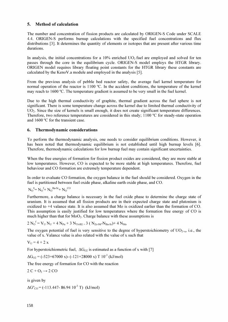
5. Method of calculation The number and concentration of fission products are calculated by ORIGEN-S Code under SCALE 4.4. ORIGEN-S performs burnup calculations with the specified fuel concentrations and flux distributions [3]. It determines the quantity of elements or isotopes that are present after various time durations. In analysis, the initial concentrations for a 10% enriched UO2 fuel are employed and solved for ten passes through the core in the equilibrium cycle. ORIGEN-S model employs the HTGR library. ORIGEN model requires library floating point constants for the HTGR library these constants are calculated by the KenoV.a module and employed in the analysis [5]. From the previous analysis of pebble bed reactor safety, the average fuel kernel temperature for normal operation of the reactor is 1100 ºC. In the accident conditions, the temperature of the kernel may reach to 1600 ºC. The temperature gradient is assumed to be very small in the fuel kernel. Due to the high thermal conductivity of graphite, thermal gradient across the fuel sphere is not significant. There is some temperature change across the kernel due to limited thermal conductivity of UO2. Since the size of kernels is small enough, it does not create significant temperature differences. Therefore, two reference temperatures are considered in this study; 1100 ºC for steady-state operation and 1600 ºC for the transient case. 6. Thermodynamic considerations To perform the thermodynamic analysis, one needs to consider equilibrium conditions. However, it has been noted that thermodynamic equilibrium is not established until high burnup levels [6]. Therefore, thermodynamic calculations for low burnup fuel may contain significant uncertainties. When the free energies of formation for fission product oxides are considered, they are more stable at low temperatures. However, CO is expected to be more stable at high temperatures. Therefore, fuel behaviour and CO formation are extremely temperature dependent. In order to evaluate CO formation, the oxygen balance in the fuel should be considered. Oxygen in the fuel is partitioned between fuel oxide phase, alkaline earth oxide phase, and CO. NO
0= NOf+ NO
Ba-Sr+ NOCO
Furthermore, a charge balance is necessary in the fuel oxide phase to determine the charge state of uranium. It is assumed that all fission products are in their expected charge state and plutonium is oxidized to +4 valance state. It is also assumed that Mo is oxidized earlier than the formation of CO. This assumption is easily justified for low temperatures where the formation free energy of CO is much higher than that for MoO2. Charge balance with these assumptions is 2 NO
f = VU NU + 4 NPu + 3 NYt-RE + 3 ( NZr-Nb-NBa-Sr)+ 4 NMo
The oxygen potential of fuel is very sensitive to the degree of hyperstoichiometry of UO2+x, i.e., the value of x. Valance value is also related with the value of x such that VU = 4 + 2 x For hyperstoichiometric fuel, ∆GO2 is estimated as a function of x with [7] ∆GO2 = (-523+67000 x)- (-121+28000 x) T 10-3 (kJ/mol) The free energy of formation for CO with the reaction 2 C + O2 → 2 CO is given by ∆GºCO = (-113.447- 86.94 10-3 T) (kJ/mol)
158

The relation between partial pressures of O2 and CO for the thermodynamic equilibrium condition is then ∆GºCO = RT ln (P2
CO/PO2 ) Partial pressure of CO can be estimated by PCO = NCO / (NCO + NXe + NKr + NI) In order to evaluate the chemical state of fuel oxygen balance, charge balance, fuel oxygen potential and CO formation free energy equations are combined together and a transcendental equation is obtained in terms of the parameter x, the deviation from stoichiometry. The value of x obtained by solving this equation allows the calculation of ∆GO2 and PCO. One aim of this study is to calculate internal pressure of coated particle to assess safety characteristics. This is accomplished by considering SiC layer rigid so that internal volume does not change. The volume available for gaseous species may then be determined by subtracting solid volume from the total volume. One may calculate the solid volume at any instant considering the swelling effect of solid fission products. Swelling due to solid fission products is calculated by [7] ∆V/V = (∑ Yi vi/vu -1 ) β The overall contribution of solid fission products is expected to be 0.3-0.5%. In addition to porosity in the fuel kernel, free volumes in the buffer layer as well as IPyC are considered in the calculation of Once the number of CO molecules produced is calculated using above given relations, the total number of gas molecules is obtained . N = NCO + NXe + NKr + NI Other fission products in the gaseous form may be added into summation. Then, the internal pressure can be calculated by the ideal gas law. 7. Results and conclusions Typical chemical configuration of fuel is evaluated by the burnup code ORIGEN-S. The accumulation of fission products is shown in Fig. 2 for variable local neutron flux according to MEDUL cycle. CO formation and contribution towards the internal pressure buildup are calculated using the methodology explained in the previous section. These calculations are carried out for several cases. The first case is for the normal operation of the reactor and for 1100 ºC. Fission product data are obtained considering MEDUL fuel management strategy. Local flux levels are employed as fuel batches change their position in the core. This case is named Case I. Total internal pressure and contributions of CO as well as gaseous fission products are shown in Fig. 3. Internal gas pressure for this case is about 6 MPa at the end of operation. In another case (Case II) , fuel is assumed to be irradiated at constant flux of throughout the operation. This case represents a high burnup fuel with about 80 000 MWd/t burnup. Internal pressure increases up to 24.9 MPa for this case. To assess the transient case, fuel chemistry and CO formation calculations are repeated for 1600 ºC. It is observed that 9.59 MPa is reached for Case I. Calculations for Case II did not produce reliable results for 1600 ºC. This case needs more detailed analysis to produce acceptable results. Fuel chemistry and CO formation calculations are considered in this study for a typical pebble bed gas cooled reactor. Calculated internal pressures are below the critical level to cause failure. However, results obtained in this study should be supported by other information such as creep, shrinkage, thermal expansion, and mechanical analysis in order for safety assessment and failure analysis. Results reported in this study should contain significant deviations from true observations. This is attributed to the absence of thermodynamic equilibrium during the operation and limited oxygen transport in the kernel. Another possible source of error is the relation between the oxygen potential of fuel and the degree of hyperstoichiometry. Employment of better correlations may improve results.
159
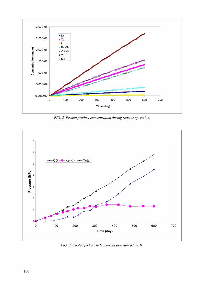
0.00E+00
5.00E-09
1.00E-08
1.50E-08
2.00E-08
2.50E-08
3.00E-08
0 100 200 300 400 500 600 700
Time (day)
Conc
entra
tion (
mole)
Kr XeIBa+Sr Zr+Nb Y+RE Mo
FIG. 2. Fission product concentration during reactor operation.
0
1
2
3
4
5
6
7
0 100 200 300 400 500 600 700Time (day)
Pres
sure
(MPa
)
CO Xe-Kr-I Total
FIG. 3. Coated fuel particle internal pressure (Case I).
160

REFERENCES [1] MILLER, G.K., PETTI, D.A., VARACELLE, D.J., MAKI, J.T., “Statistical Approach and
Benchmarking for Modelling of Multi-Dimensional Behaviour in TRISO-Coated Fuel Particles”, Journal of Nuclear Materials, 317, (2003) pp. 69-82.
[2] MARTIN, D.G., “Considerations Pertaining to the Achievement of High Burn-ups in HTR Fuel”, Nuclear Engineering and Design, 213, (2002) pp.241-258.
[3] HERMANN, O.W., WESTFALL, R.M., “ORIGEN-S SCALE System Module to Calculate Fuel Depletion, Actinide Transmutation, Fission Product Burnup and Decay, and Associated Radiation Source Terms”, NUREG/CR – 0200 Revision 6 Volume 2, Section F7, (1998).
[4] SIKIK, U.E., “Neutronic and Thermal Hydraulic Calculations of the Pebble Bed Modular Reactor”, Hacettepe University Master of Science Thesis, (2003).
[5] CECEN, Y., COLAK, U., KADIROGLU, O.K., “Burnup Dependent Core Neutronic Analysis for PBMR”, Proceedings of the Conference on High Temperature Reactors, HTR-2002, Petten, NL, April 22-24, 2002 Organized by HTR-TN in cooperation with the European Nuclear Society (ENS) and the IAEA International Atomic Energy Agency, Vienna (Austria), (2002) pp:1-8.
[6] PROKSCH, E., STRIGL, A., NABIELEK, H., Production of carbon monoxide during burn-up of UO2 kerneled HTR fuel particles. Journal of Nuclear Materials, 107, (1982) pp.280-285.
[7] OLANDER, D.R., Fundamental Aspects of Nuclear Reactor Fuel Elements, NTIS, Springfield Virginia (1974).
161
High temperature materials – The challenge for future advanced gas cooled reactors
W. Hoffelner Department of Nuclear Energy and Safety, Paul Scherrer Institute
Wuerenlingen, Switzerland Abstract. Advanced gas cooled reactor systems for future combined cycle applications (electricity and process heat) are planned to operate at temperatures up to or even above 1000 ºC. The reliable and safe operation of such plants requires materials that are able to carry loads at these temperatures in impure helium and under neutron irradiation. The most exposed components are the pressure vessel, reactor internals, gas turbine, pipes and valves. Considering the envisaged long operating time (6 years for replaceable components) life time assessments and extrapolation methods are necessary for the determination of damage evolution and long term behaviour of the reactor components. This paper gives a summary of candidate materials and possible approaches to life-time assessment. The paper concentrates mainly on very high temperature reactors (VHTR), some material aspects of gas cooled fast reactors (GFR) are considered, too.
1. Introduction There is an increasing interest in gas cooled reactors as a basis for future advanced energy systems. Such concepts are therefore being investigated in several arenas including the worldwide Generation IV (GIF) initiative [1], European Community projects [2] and national R&D projects. The aim of advanced reactor systems is to provide heat for direct energy conversion using a high temperature turbine and also to provide process heat (e.g. for use in hydrogen production) in a combined cycle process. Current high temperature reactor (HTR) designs operate at gas temperatures of up to 850 °C. Gas temperatures for the next generation (deployable by 2017) are expected to be higher than 950 °C and temperatures in excess of 1000 °C are expected for future advanced VHTR’s gas reactors. These temperature increases are due to the expected higher net plant efficiency (for a recuperated Brayton Cycle) as well as the expected higher efficiency of hydrogen production [3,4]. gas temperatures for a gas-cooled fast reactor (GFR) are lower (850 °C), but fast temperature excursions (up to 1600 °C) can occur in case of loss of coolant event. To design safe reactor plants, materials are required that are able to withstand extreme service exposures (temperatures, neutron spectra, creep) over a time period of at least 6 years (replaceable parts). The main parts of an advanced combined cycle nuclear plant based on a gas cooled reactor are: reactor pressure vessel, reactor internals (including control rods), piping, helium gas turbine, intermediate heat exchanger, high temperature process equipment (hydrogen plant). The current state of the art materials for these applications will be summarized and potential materials for the near term deployment and for gas temperatures exceeding 1000 °C will be discussed. The question regarding the choice of reactor materials remains the same regardless of whether the pebble bed or prismatic reactor design is considered. 2. Candidate materials A summary of the materials for HTR-designs at different gas temperatures is given in Table 1. Similarities in materials for VHTR and GFR application are shown in Table 2. Aspects of the different components will be discussed in the next sections.
162

2.1. Pressure vessel The pressure vessel of a HTR must be made of steel that can withstand stresses for temperatures up to 400 °C in current designs and up to 500 °C in the currently considered future designs [5]. At these temperatures the stresses upon the pressure vessel can lead to creep and/or relaxation. However, to design a pressure vessel with creep taken into account would require a lot of additional design data and curves (including creep strain data, multiaxiality and creep, creep of welds, notch sensitivity etc.) as well as procedures for surveillance under creep conditions. The avoidance of creep needs design measures and highly creep resistant materials. Currently at the laboratory for material behabiour (LWV) in PSI, steels for the reactor pressure vessel (RPV) can be used for temperatures up to 350 °C [6]. The classes of ferritic (NiCr)MoV- steels and the more creep resistant 9-12% martensitic chromium steels are very well established creep resistant materials for a temperature regime of 400 to 550 °C. They have been used in chemical plants, in boilers, in steam- and gas turbines and in jet engines. Temperature extensions to 600 °C have been tried for different applications (e.g. large steam turbine rotor forgings). A summary of these developments is given in [7]. As a result of its low activation and its high thermal conductivity this class of steels is also very interesting for fusion applications [8]. The development has now reached a stage where no significant improvements are expected by changing the chemical composition. Only a change of the matrix (from ferritic martensitic to austenitic) or reinforcements of the martensitic matrix (e.g. oxide dispersion, Fig. 1) could lead to significant improvement of creep properties. Due to the difficulties in producing large components, reliable welds and in non destructive testing it can be stated that according to current knowledge these materials. cannot be used as reactor pressure vessels. TABLE 1. SUMMARY OF POSSIBLE MATERIALS FOR (V)HTRS. THE TEMPERATURES INDICATE THE REACTOR GAS OUTLET TEMPERATURE (DS DIRECTIONALLY SOLIDIFIED, SC SINGLE CRYSTAL, ODS OXIDE DISPERSION STRENGTHENED, TBC THERMAL BARRIER COATING, IHX INTERMEDIATE HEAT EXCHANGER, LWR LIGHT WATER REACTOR, RPV REACTOR PRESSURE VESSEL
Component T< 850 °C 850 °C <T< 950 °C T> 950 °C Reactor Pressure Vessel
LWR-RPV (ferritic)
2 1/4 Cr 1 Mo (ferritic) 9-12 % Cr-steel (martensitic)
9-12 % Cr steel (martenisitic)
Control Rod Ni-base superalloy Ni base superalloy, SiC/C, SiC/SiC
SiC/C, SiC/SiC Graphite, ceramic internals
Graphite Graphite (new grades), SiC/C or SiC/SiC structural parts
Graphite (new grades), SiC/SiC structures, (superplastic) ceramics
Metallic internals Steels Steels, Ni-base superalloys, ODS
Steels, Ni-base superalloys, inter-metallics, ODS
Piping/IHX/valves Ni-base superalloys Advanced Ni-base superalloys (eventually with TBC-coatings)
Advanced Ni-base superalloys with TBC-coatings, cooled designs, ceramics, intermetallics, composite structures
He-Gas Turbine: Blades/Vanes Rotor
Ni-base superalloys {gamma-prime γ' hardening) Ferritic-martensitic steels (cooled designs)
Ni-base superalloys (DS, SC) Ferritic-martensitic steels (cooled designs), Ni-base superalloys (γ' - hardening)
Ni-base superalloys (DS, SC), cooled designs, ODS, intermetallics, refractory alloys, composites Ni-base superalloys (γ'-hardening),advanced production technology (cooled) composites 163

TABLE 2. COMPARISON OF MATERIAL SIMILARITIES BETWEEN VHTR AND GFR VHTR GFR CONDITIONS Neutrons Thermal fast Max. temperature > 900 C Max. 850 C Inlet temperature < 490 C 490 C Loss of coolant Up to 1200 C slowly Up to 1600 C in 100 sec COMPONENTS Reactor pressure Vessel 9-12% Cr 2 1/4 Cr 1Mo, 9-12 % Cr Internals: Reflector Claddings Internals (structural)
- - C, SiC/SiC Ceramics
ZrxSiy (Intermetallic) ODS, SiC/SiC, MMC Ceramics, Composites, Refractory alloys
Turbine: Blades Rotor
DS, SX Intermetallics, Ceramics Ni-base
Equiaxed cast (IN-738, IN-792) Ni-base
Pipings etc. IN-617, HA-230 IN-800H The choice of material for a VHTR depends on the design of the vessel and the design rules. There are claims that a 2 1/4 Cr 1 Mo-steel would be sufficient but the majority of researchers propose an advanced steel of the 9-12 % Cr-class. It should however be noted that use of 9-12% martensitic chromium steels for RPVs represent a significant challenge for complete through-section heat treatment, fabrication, welding and post weld heat treatment. It should also be noted that 9-12% martensitic chromium steels are not currently included in the ASME Boiler and Pressure Vessel Code but there are plans to include 9Cr-1Mo (T91) steel in future revisions. 2.2. Reactor internals The reactor internals of a current HTR mainly consist of a graphite core, control rods (superalloy Hastelloy XR) and steel support structures. A fundamental problem of graphite in nuclear reactor cores is the deterioration of mechanical and other properties as a result of the neutron irradiation. The primary source of degradation is the stresses that develop during irradiation [9]. Graphite will remain the core part of VHTR’s and therefore the irradiation behaviour of different graphite properties is to be investigated in different international research projects, e.g. [10]. It also might be worth considering designs in which bricks or core parts are replaced by composite structures filled with graphite for use as a moderator. The advantage of composite structures is that their structural integrity is maintained even when locally cracked. This is the reason why black composite ceramics (C/C, SiC/C and SiC/SiC) are currently being investigated as future materials for smaller structural parts and liners. A possible near term application for black ceramic compounds is as components of the control rod [1,6]. Different properties of C- and SiC-type materials are therefore currently being investigated (e.g. Fig. 2).
164

FIG. 1. Microstructure of a ferritic ODS alloy (TEM micrograph)ODS = oxide dispersion strengthened alloys.
FIG. 2. Microstructure and results of punch test in different orientation of a SiC/C fibre reinforced ceramic.
SiC/C ceramic matrix composite for VHTR application
perpendicular to the fiberparallel to the fiber
C-Fibres
C-Fibre
SiC-Matrix
TEM
SEM
165
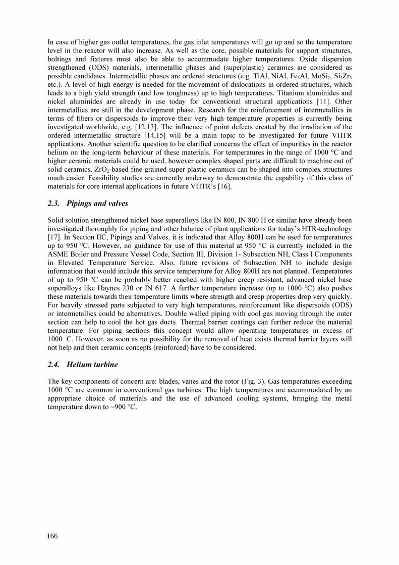
In case of higher gas outlet temperatures, the gas inlet temperatures will go up and so the temperature level in the reactor will also increase. As well as the core, possible materials for support structures, boltings and fixtures must also be able to accommodate higher temperatures. Oxide dispersion strengthened (ODS) materials, intermetallic phases and (superplastic) ceramics are considered as possible candidates. Intermetallic phases are ordered structures (e.g. TiAl, NiAl, Fe3Al, MoSi2, Si2Zr3 etc.). A level of high energy is needed for the movement of dislocations in ordered structures, which leads to a high yield strength (and low toughness) up to high temperatures. Titanium aluminides and nickel aluminides are already in use today for conventional structural applications [11]. Other intermetallics are still in the development phase. Research for the reinforcement of intermetallics in terms of fibers or dispersoids to improve their very high temperature properties is currently being investigated worldwide, e.g. [12,13]. The influence of point defects created by the irradiation of the ordered intermetallic structure [14,15] will be a main topic to be investigated for future VHTR applications. Another scientific question to be clarified concerns the effect of impurities in the reactor helium on the long-term behaviour of these materials. For temperatures in the range of 1000 °C and higher ceramic materials could be used, however complex shaped parts are difficult to machine out of solid ceramics. ZrO2-based fine grained super plastic ceramics can be shaped into complex structures much easier. Feasibility studies are currently underway to demonstrate the capability of this class of materials for core internal applications in future VHTR’s [16]. 2.3. Pipings and valves Solid solution strengthened nickel base superalloys like IN 800, IN 800 H or similar have already been investigated thoroughly for piping and other balance of plant applications for today’s HTR-technology [17]. In Section IIC, Pipings and Valves, it is indicated that Alloy 800H can be used for temperatures up to 950 °C. However, no guidance for use of this material at 950 °C is currently included in the ASME Boiler and Pressure Vessel Code, Section III, Division 1- Subsection NH, Class I Components in Elevated Temperature Service. Also, future revisions of Subsection NH to include design information that would include this service temperature for Alloy 800H are not planned. Temperatures of up to 950 °C can be probably better reached with higher creep resistant, advanced nickel base superalloys like Haynes 230 or IN 617. A further temperature increase (up to 1000 °C) also pushes these materials towards their temperature limits where strength and creep properties drop very quickly. For heavily stressed parts subjected to very high temperatures, reinforcement like dispersoids (ODS) or intermetallics could be alternatives. Double walled piping with cool gas moving through the outer section can help to cool the hot gas ducts. Thermal barrier coatings can further reduce the material temperature. For piping sections this concept would allow operating temperatures in excess of 1000 C. However, as soon as no possibility for the removal of heat exists thermal barrier layers will not help and then ceramic concepts (reinforced) have to be considered. 2.4. Helium turbine The key components of concern are: blades, vanes and the rotor (Fig. 3). Gas temperatures exceeding 1000 °C are common in conventional gas turbines. The high temperatures are accommodated by an appropriate choice of materials and the use of advanced cooling systems, bringing the metal temperature down to ~900 °C.
166
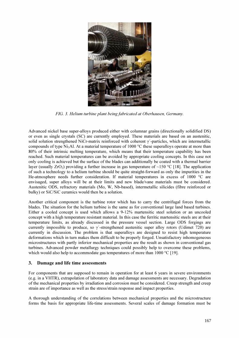
FIG. 3. Helium turbine plant being fabricated at Oberhausen, Germany.
Advanced nickel base super-alloys produced either with columnar grains (directionally solidified DS) or even as single crystals (SC) are currently employed. These materials are based on an austenitic, solid solution strengthened NiCr-matrix reinforced with coherent γ΄-particles, which are intermetallic compounds of type Ni3Al. At a material temperature of 1000 °C these superalloys operate at more than 80% of their intrinsic melting temperature, which means that their temperature capability has been reached. Such material temperatures can be avoided by appropriate cooling concepts. In this case not only cooling is achieved but the surface of the blades can additionally be coated with a thermal barrier layer (usually ZrO2) providing a further increase in gas temperature of ~150 °C [18]. The application of such a technology to a helium turbine should be quite straight-forward as only the impurities in the He-atmosphere needs further consideration. If material temperatures in excess of 1000 °C are envisaged, super alloys will be at their limits and new blade/vane materials must be considered. Austenitic ODS, refractory materials (Mo, W, Nb-based), intermetallic silicides (fibre reinforced or bulky) or SiC/SiC ceramics would then be a solution. Another critical component is the turbine rotor which has to carry the centrifugal forces from the blades. The situation for the helium turbine is the same as for conventional large land based turbines. Either a cooled concept is used which allows a 9-12% martensitic steel solution or an uncooled concept with a high temperature resistant material. In this case the ferritic martensitic steels are at their temperature limits, as already discussed in the pressure vessel section. Large ODS forgings are currently impossible to produce, so γ΄-strengthened austenitic super alloy rotors (Udimet 720) are currently in discussion. The problem is that superalloys are designed to resist high temperature deformations which in turn makes them difficult to be properly forged. Unsatisfactory inhomogeneous microstructures with partly inferior mechanical properties are the result as shown in conventional gas turbines. Advanced powder metallurgy techniques could possibly help to overcome these problems, which would also help to accommodate gas temperatures of more than 1000 °C [19]. 3. Damage and life time assessments For components that are supposed to remain in operation for at least 6 years in severe environments (e.g. in a VHTR), extrapolation of laboratory data and damage assessments are necessary. Degradation of the mechanical properties by irradiation and corrosion must be considered. Creep strength and creep strain are of importance as well as the stress/strain response and impact properties. A thorough understanding of the correlations between mechanical properties and the microstructure forms the basis for appropriate life-time assessments. Several scales of damage formation must be
167
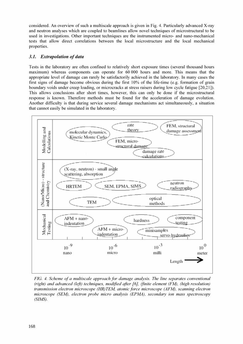
considered. An overview of such a multiscale approach is given in Fig. 4. Particularly advanced X-ray and neutron analyses which are coupled to beamlines allow novel techniques of microstructural to be used in investigations. Other important techniques are the instrumented micro- and nano-mechanical tests that allow direct correlations between the local microstructure and the local mechanical properties. 3.1. Extrapolation of data Tests in the laboratory are often confined to relatively short exposure times (several thousand hours maximum) whereas components can operate for 60 000 hours and more. This means that the appropriate level of damage can rarely be satisfactorily achieved in the laboratory. In many cases the first signs of damage become obvious during the first 10% of the life-time (e.g. formation of grain boundary voids under creep loading, or microcracks at stress raisers during low cycle fatigue [20,21]). This allows conclusions after short times, however, this can only be done if the microstructural response is known. Therefore methods must be found for the acceleration of damage evolution. Another difficulty is that during service several damage mechanisms act simultaneously, a situation that cannot easily be simulated in the laboratory.
FIG. 4. Scheme of a multiscale approach for damage analysis. The line separates conventional (right) and advanced (left) techniques, modified after [6], (finite element (FM), (high resolution) transmission electron microscope (HR)TEM, atomic force microscope (AFM), scanning electron microscope (SEM), electron probe micro analysis (EPMA), secondary ion mass spectroscopy (SIMS).
168

Well known methods for acceleration include the use of more aggressive environments or, in case of creep, testing at operation temperatures but at higher stresses or vice-versa. Assuming that there is a unique parametric relationship between stresses, temperature and creep rupture life, long term behaviour can be predicted from short term behaviour. Examples of typical approaches include the Iso-Stress-Method (see Fig. 5 replotted from [23]), the Larson-Miller parameter or the Manson-Haferd parameter. Very often the validity of a potential law between secondary creep rate and creep rupture life is assumed (Monkman-Grant rule) [24]. Although these parameters were originally developed for metallic materials only, they are also applied to almost all materials including ODS, intermetallics [25] and even SiC/SiC [26] and other ceramics. The danger of such an approach lies in the fact that deformation mechanisms can be stress dependent and/or temperature dependent and this can give misleading predictions. For the application of proper extrapolation methods an understanding of the damage mechanisms is necessary. The presence of irradiation complicates the situation even more because the neutrons create a high density of point defects which can interact in-situ with dislocations and/or diffusion controlled creep mechanisms (see Fig. 6 replotted from [27]). Short term creep tests under irradiation at high temperatures can help to clarify the picture. 3.2. Life-time assessments The linking of mechanical properties with microstructural damage for high temperature applications (interaction creep-fatigue-environment) has attracted material scientists concerned with life assessments of components since the 1970’s e.g. [28,29].
FIG. 5. Iso-Stress plot for different Ni-base superalloys showing a linear relationship between log stress rupture time and temperature23.
169
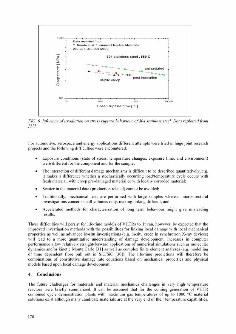
FIG. 6. Influence of irradiation on stress rupture behaviour of 304 stainless steel. Data replotted from [27]. For automotive, aerospace and energy applications different attempts were tried in huge joint research projects and the following difficulties were encountered: • Exposure conditions (state of stress, temperature changes, exposure time, and environment)
were different for the component and for the sample; • The interaction of different damage mechanisms is difficult to be described quantitatively, e.g.
it makes a difference whether a stochastically occurring load/temperature cycle occurs with fresh material, with creep pre-damaged material or with locally corroded material;
• Scatter in the material data (production related) cannot be avoided; • Traditionally, mechanical tests are performed with large samples whereas microstructural
investigations concern small volumes only, making linking difficult; and • Accelerated methods for characterization of long term behaviour might give misleading
results. These difficulties will persist for life-time models of VHTRs to. It can, however, be expected that the improved investigation methods with the possibilities for linking local damage with local mechanical properties as well as advanced in-situ investigations (e.g. in-situ creep in synchrotron X-ray devices) will lead to a more quantitative understanding of damage development. Increases in computer performance allow relatively straight-forward applications of numerical simulations such as molecular dynamics and/or kinetic Monte Carlo [31] as well as complex finite element analyses (e.g. modelling of time dependent fibre pull out in SiC/SiC [30]). The life-time predictions will therefore be combinations of constitutive damage rate equations based on mechanical properties and physical models based upon local damage development. 4. Conclusions The future challenges for materials and material mechanics challenges in very high temperature reactors were briefly summarized. It can be assumed that for the coming generation of VHTR combined cycle demonstration plants with maximum gas temperatures of up to 1000 °C material solutions exist although many candidate materials are at the very end of their temperature capabilities.
170

The main emphasis has to be put on the establishment of design data bases (9-12% Cr-steel, nickel-base super alloys, graphite) and on design concepts that are in accordance with the envisaged materials. Development of composite materials (C/C, SiC/SiC, ODS) is necessary for some core internal applications (e.g. control rod, fixing and supporting elements). Coatings and thermal barrier layers should be considered as a design requirement. The fact that the materials currently under discussion are at their temperature limits highlights the need for a quantitative understanding of damage formation and damage evolution as a basis for proper life-time assessments. For future commercial systems with even higher gas temperatures new materials like advanced ceramic, metallic and intermetallic materials, and reinforced materials with dispersoids or fibres must be further explored and developed to a stage at which components can be produced.
ACKNOWLEDGEMENTS The author would like to thank PSI for supporting the work on high temperature materials for VHTR applications. Helpful discussions with members of the GIF-VHTR steering committee and with the European HTR group are very much acknowledged.
REFERENCES [1] U.S. DEPARTMENT OF ENERGY, A technology roadmap for Generation IV nuclear
energy systems, U.S. DOE Nuclear Energy Research Advisory Committee and the Generation IV International Forum, GIF-002-00, December (2002).
[2] HUGON, M., CASALTA, S., Research on Advanced Systems in the Euratom Framework Programmes,, Proc. of High Temperature Reactor School, HTR/ECS 2002, November 4-8, Cadarache, France (2002)
[3] SOUTHWORTH, F., Next Generation Nuclear Plant, MIT ANS Seminar, Sept 29, 2003, MIT Section of the American Nuclear Society, (2003),http://mit.edu/ans/www/seminar.html
[4] SOUTHWORTH, F., Very High Temperature Gas Cooled Reactor Systems, Proc. of American Nuclear Energy Symposium, ANES 2002, October 16-18, 2002 Miami, Florida, (2002).
[5] CARRE, F., “Overview of CEA Studies on Future Nuclear Energy Studies”, Proc. NEA workshop on R&D needs for current and future nuclear systems, November 6-8, 2002, Paris NEA (2002), http://www.nea.fr/html/science/rd/presentations/2-1.pdf.
[6] BUCKTHORPE, D.E., “HTR materials & technologies (HTR Metallic Materials)”, Proc. Of High Temperature Reactor School, Cadarache, France, Nov 4-8, 2002 HTR/ECS (2002).
[7] VISWANATHAN, R., BAKKER, W.T., “Materials for Ultra-supercritical Fossil Power Plants”, TR-114750, EPRI, Palo Alto, CA, February, (2000).
[8] JITSUKAWA, S., TAMURA, M., VAN DER SCHAAF, B., KLUEH, R.L., ALAMO, A., PETERSEN, C., SCHIRRA, M., SPAETIG, P., ODETTE, G.R., TAVASSOLI, A.A., SHIBA, K., KOHYAMA, A., KIMURA, A., “Development of an extensive database of mechanical and physical properties for reduced-activation martensitic steel F82H”, Journal of Nuclear Materials, 307–311 (2002) pp. 179–186.
[9] SHTROMBAKH, Y.A., GUROVICH, B.A., PLATONOV, P.A., “Radiation Damage of Graphite and Carbon-Graphite”, Journal of Nuclear Materials 225 (1995) pp. 273-302.
[10] VON LENSA, W., “The Role of International Collaboration within the European High-Temperature Reactor-Technology Network (HTR-TN)”, Seminar on HTGR Application and Development, March 19-21,2001, Beijing, China, Tsinghua Univ., China , http://www.inet.tsinghua.edu.cn/english/HTR_meetings_S/file_doc/ownpp/5 .
[11] NAZMY, M., STAUBLI, M., ONOFRIO, G., LUPINC, V., “Surface defect tolerance of cast TiAl alloy in fatigue”, Scripta Materialia 45 (2001) pp. 787-792.
[12] WANG, G., JIANG, W., BAI, G., CHEN, D., “Si3N4 rodlike crystal-reinforced MoSi2 matrix composites“, Materials Letters 58 (2004) pp. 308– 311.
[13] COURTRIGHT, E.L., “A comparison of MoSi2 matrix composites with other silicon-base composite systems“, Materials Science and Engineering A261, (1999) 53–63.
171

[14] MOTTA, A.T., “Amorphization of intermetallic compounds under irradiation – a review”, Journal of Nuclear Materials, 244, (1997) 227-250.
[15] HISHINUMA, A., “Radiation Damage of TiAl intermetallic alloys”, Journal of Nuclear Materials, 239, (1996) 267-272.
[16] ISHIHARA, M., SHIBATA, T., WAN, C., BABA, S., MOTOHASHI, Y., HOSHIYA, T., “Effects of Superplastic Deformation on Thermal and Mechanical Propertiesof 3Y-TZP Ceramics”, The Second Information Exchange Meeting on Basic Studies in the Field of High Temperature Engineering, Headquarters of Organisation for Economic Co-operation and Development France, October, p.17 (2001), HTTP://WWW.NEA.FR/HTML/SCIENCE/HTEMP/IEM2/ABSTRACTS/HTTR2-ABSTRACTS-FOR-DIST-R0.PDF
[17] STATUS OF METALLIC MATERIALS DEVELOPMENT FOR APPLICATION IN ADVANCED HIGH-TEMPERATURE GAS-COOLED REACTORS, Nuclear Technology, Vol.66, No 1, (July 1984), Vol 66, No. 2, (August 1984), Vol. 66, No 3, (September 1984).
[18] AHMANIEMI, S., VUORISTO, P., MÄNTYLÄ, T., “Thick Thermal Barrier Coatings - State-of-the-Art”, Euroceram Newsletter (2003), http://www.euroceram.com/en/news/news_7_4.cfm.
[19] BILLOT, P., CEA Saclay, private communication March 2004. [20] KAISAND, L.R., MOWBRAY, D.F., “Relationships between LCF and fatigue crack
growth”, J. Test Eval., Vol. 7, (1979) pp. 270. [21] HOFFELNER, W., “On the correlation between life-time and crack growth laws under
HTLCF loading”, Low Cycle Fatigue and Elasto-Plastic Behaviour of Materials, Ed.K.-T.Rie, Elsevier, (1987) p.622.
[22] KOHYAMA, A., Advanced Ceramics Composite Integration Reseach, Activity for Gas-Cooled Fast Reactor, Gen IV International Forum GFR Steering Committee Meeting, Idaho May 21st, (2003).
[23] HOFFELNER, W., “Creep dominated processes”, High Temperature Alloys for Gas Turbines and other Applications 1986. Eds.:W.Betz et al.,D.Reidel Publ.Comp. p. 413, Dordrecht (1986).
[24] ACCELARATED AGING OF MATERIALS AND STRUCTURES: The Effects of Long-Term Elevated-Temperature, Committee on Evaluation of Long-Term Aging of Materials and Structures Using Accelerated Test Methods, Commission on Engineering and Technical Systems, National Research Council, Page display interface copyright 1999 and 2003, the National Academies Press. Electronic version (2003).
[25] FUJI, A., et al., International Journal of pressure Vessels and Piping 80, 435-440, (2003) [26] ZHU, S., MIZUNO, M., KAGAWA, Y., MUTOH, Y., “Monotonic tension, fatigue and
creep behavior of SiC-fiber-reinforced SiC-matrix composites: a review”, Composites Science and Technology 59, (1999) 833-851.
[27] KURATA, Y., ITABASHI, Y., MIMURA, H., KIKUCHI, T., AMEZAWA, H., SHIMAKAWA, S., TSUJI, H., SHINDO, M., “In-pile and post-irradiation creep of type 304 stainless steel under different neutron spectra”, Journal of Nuclear Materials 283-287, (2000) 386-390.
[28] FATIGUE AT ELEVATED TEMPERATURES, ASTM STP 520, American Society for Testing and Materials, ASTM (1973).
[29] HIGH TEMPERATURE ALLOYS FOR GAS TURBINES AND OTHER APPLICATIONS 1986. Eds.:W.Betz et al., D.Reidel Publ.Comp., Dordrecht (1986).
[30] SERIZAWA, H., MURAKAWA, H., “SiC/SiCCreep Strength- New FEM Analysis of Time-Dependent Crack Growth in SiC/SiC Composites” - International Town Meeting on SiC/SiC Design and Material Issues for Fusion Systems Oak Ridge National Laboratory, January 18-19 (2000).
[31] WIRTH, B.D., ODETTE, G.R., CATURLA, M.J., DIAZ DE LA RUBIA, T., HEINISCH, H.L., STOLLER, R.E., “Aspects of Multiscale Modeling: Kinetic Monte Carlo, Cascade Aging and Dislocation - Obstacle Interactions”, U.S. DOE Office of Fusion Energy Sciences Fusion Materials Sciences Program Peer Review, Santa Barbara (2001).
172

Session 3
FUEL PERFORMANCE AND TECHNOLOGY
S. Venter South Africa
K. Bakker
The Netherlands
173

174

Post-irradiation testing of HTR-fuel elements under accident conditions
H. Kostecka, J. Ejton, W. De Weerd, E.H. Toscano European Commission, JRC-Karlsruhe, Institute for Transuranium Elements Karlsruhe, Germany
Abstract. The European project aimed at development of high temperature reactor (HTR) technology includes developments in the fields of reactor physics, fuel technology, safety, material needs and the feasibility of key components and systems. A key point in the domain of fuel technology is the testing of the irradiation behaviour of new fuel types and their fabrication methods. In this context, the testing of irradiated fuels under loss-of-coolant accident conditions will be needed to assess the quality of new fuel concepts and fabrication methods. That means principally, the evaluation of the release behaviour of fission gases (Xe, Kr) and solid fission products (Cs, Sr, Ag, etc) under these conditions. In the past, the so-called cold finger apparatus (KÜFA) was developed in the Forschungszentrum Jülich (FZJ) to test HTR-fuel design and fabrication methods. Using this device, the fission product release from defected particles could be tested up to 1800 °C. Recently, an upgraded version of the KÜFA has been installed in the hot cells of the Institute for Transuranium Elements. In the present paper, a comprehensive description of the apparatus is presented, the calibration procedures described, and the future experimental programme discussed. 1. Introduction The opinion of nuclear power in most EU member states is suffering from the public concern about the acceptability of presently established nuclear technology, mainly due to safety issues, but also from the increasing difficulty of keeping economic competitiveness in a de-regulated market. At present, light water reactors dominate worldwide nuclear energy production. Some advanced designs like the European pressurised water reactor (EPR) meet the safety requirements, but are based on active safety systems which are costly and require more elaborate safety demonstration. On the other hand, the HTRs, being inherently safe, can meet all the requirements, reducing costs without affecting the safety. Besides the safety, the HTRs offer the following advantages: - Proliferation-resistant fuel type; - Reduction of the radioactive waste burden; - Ultra high burn-up potential (> 200 GWd/t U); - Well-known and proven technology (GCRs, AVR, Dragon, Fort Saint Vrain, etc.); - Robustness of the fuel; - Social acceptance through improved safety; - Energy supply diversity (electricity, heat); and - Competitiveness (modular concept).
175

In the framework of a shared cost action (SCA) of the European Commission, a European project aimed to the development of the high temperature reactor (HTR) technology has been approved. In the domain of fuel technology is the testing of the irradiation behaviour of new fuel types and their fabrication methods. In this context, the post-irradiation testing of irradiated fuels under loss-of-coolant accident conditions will be needed to assess the quality of new fuel concepts and fabrication methods. That means principally, the evaluation of the release behaviour of fission gases (Xe, Kr) and solid fission products (Cs, Sr, Ag, etc) under these conditions. In the past, the so-called cold finger apparatus (KÜFA) was developed in FZJ to test HTR-fuel design and fabrication methods. Using this device, the fission product released from defect particles could be tested up to 1800 °C [1-3]. In the context of the SCA/HTR-technology, an up-graded version of the KÜFA has been installed in the hot cells of the Institute for Transuranium Elements. In the present paper, a comprehensive description of the apparatus is presented, the calibration procedures described, and the future experimental programme discussed. 2. Test background The central aspect of the safety philosophy for a high temperature reactor (HTR) is the retention of fission products - particularly those of the iodine nuclides - in the fuel elements during operation and accidents. For this reason, the determination of the number of damaged particles constitutes the central objective of measuring the fission gas release in the reactor and in the extensive post-irradiation examinations under accident conditions. In modern production methodologies, the heavy metal contamination of fuel elements is kept very low. Consequently, solely the number of defective particles establishes fission gas or iodine release. During a loss-of-coolant accident, the temperature in the core of a HTR will increase. The amount of this increase depends on the geometrical design of the reactor and the nature of the accident. For the extreme case of pressure loss in the core with the failure of all heat sinks, temperatures as high as 2000 C can be reached in a medium size HTR. On the other hand, for the case of small HTRs and the modular-concept in Germany, relatively low accident temperatures between 1400 and less than 1800 C have been anticipated. With the increase of the core temperature above normal, fission products may be released from the fuel elements into the primary circuit and, eventually, into the environment. For a realistic assessment of the fission product release, the conditions in the reactor core have to be simulated. The relevant fission products to be measured and their relevance in case of accident are given in Table 1. TABLE 1. RELEVANT FISSION PRODUCTS TO BE MEASURED
Fission Product Half life Relevance assessment 131I 8 days Greatest significance for design and licensing 137Cs/ 134Cs 90Sr 30/ 2 a
29 years Long term behaviour after extreme accidents and risk analysis
110mAg 253 days Small inventory, short half-life. Important for maintenance 85Kr 133Xe
11 years 5 days Not accident relevant. Particle defect indicator
176

3. Description of the cold-finger apparatus 3.1.. General The test requirements, arising from the necessity of evaluation of HTR-fuel elements for licensing purposes, led in the past to the development in FZJ of this highly specialised test equipment capable of coping with entire fuel elements (pebbles or compacts) as well as individual coated particles. The basic function of this device is to heat the fuel elements up to the expected temperature in a dynamic He-atmosphere, and then to measure the fission product release. In the current up-graded version, designed for accident simulation tests of future HTRs, temperatures up to 2000 °C can be reached. The fuel element is supported by three pins in the centre of a tantalum tube placed inside the furnace; helium flows through this tube from the bottom to the top (Fig. 1). The tantalum tube and the fuel element are heated by an electrical resistance heater, which likewise consists of tantalum.
FIG. 1. Cold-finger apparatus (KÜFA). A W/Re-thermocouple, placed near to the specimen, measures the actual temperature during the tests. This thermocouple can be replaced if needed and serves, simultaneously, for the electronic regulation of the temperature of the furnace. 3.2.. Measurement of fission gas release The measurement of fission gases under accident conditions allows the detection of failed fuel elements. Through the analysis of the release curves, individual failed particles in the fuel element
177
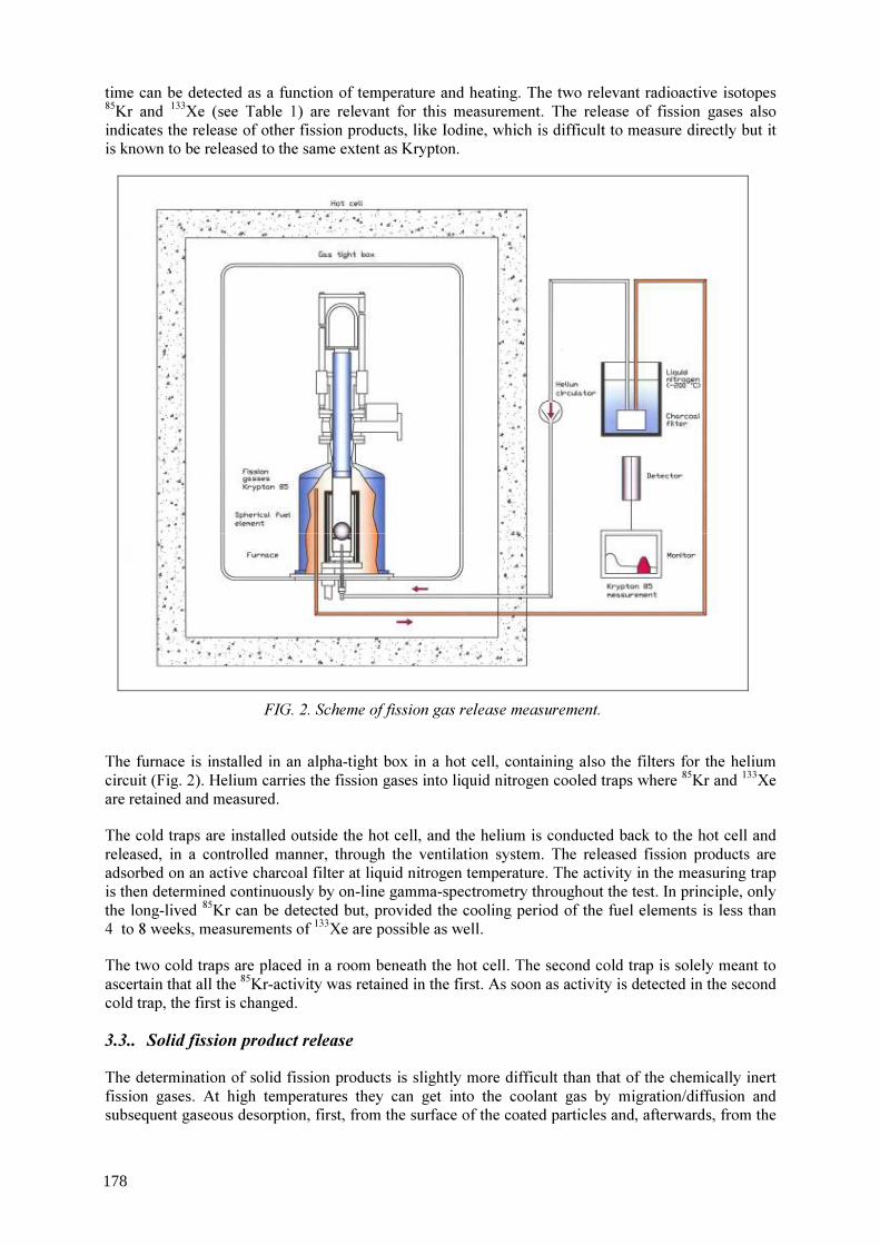
time can be detected as a function of temperature and heating. The two relevant radioactive isotopes 85Kr and 133Xe (see Table 1) are relevant for this measurement. The release of fission gases also indicates the release of other fission products, like Iodine, which is difficult to measure directly but it is known to be released to the same extent as Krypton.
FIG. 2. Scheme of fission gas release measurement.
The furnace is installed in an alpha-tight box in a hot cell, containing also the filters for the helium circuit (Fig. 2). Helium carries the fission gases into liquid nitrogen cooled traps where 85Kr and 133Xe are retained and measured. The cold traps are installed outside the hot cell, and the helium is conducted back to the hot cell and released, in a controlled manner, through the ventilation system. The released fission products are adsorbed on an active charcoal filter at liquid nitrogen temperature. The activity in the measuring trap is then determined continuously by on-line gamma-spectrometry throughout the test. In principle, only the long-lived 85Kr can be detected but, provided the cooling period of the fuel elements is less than 4 to 8 weeks, measurements of 133Xe are possible as well. The two cold traps are placed in a room beneath the hot cell. The second cold trap is solely meant to ascertain that all the 85Kr-activity was retained in the first. As soon as activity is detected in the second cold trap, the first is changed. 3.3.. Solid fission product release The determination of solid fission products is slightly more difficult than that of the chemically inert fission gases. At high temperatures they can get into the coolant gas by migration/diffusion and subsequent gaseous desorption, first, from the surface of the coated particles and, afterwards, from the
178

surface of the fuel. On the other hand, such fission products are re-deposited by adsorption on cooler surfaces, and this deposition mechanism is exploited for trapping solid fission products in the cold finger test rig. To detect the release of solid fission products, a water-cooled cold finger protrudes into the hot tantalum tube, at the end of which an easily replaceable condensation plate is held. The solid fission products released from the fuel element are deposited on this plate which has a temperature of less than 100 °C, typically 40 to 80 °C depending on the testing temperature. This temperature has to be compared to the specimen temperature, which is in the range of 1600 - 2000 °C. During the test, the cold finger can be removed from the furnace through an air-lock system (Fig. 3) without needing to cool-down the specimen. In fact, the Helium circulation is maintained during the plate-changes, which assures the continuous monitoring of the specimen and the detection any coated particle failure.
FIG. 3. Schema of the solid fission products measurement. After replacing the condensation plate, the cold finger is returned back to its position into the furnace. The plate is normally changed once or twice a day but, if necessary, this operation can be performed more frequently. The changing procedure lasts only few minutes and needs relatively easy manipulation. The used plates are taken out of the hot cell to be measured by gamma- spectrometry in a low background laboratory to be measured. Measurement of gamma emitters such as 137Cs, 134Cs and 131I is relatively simple, because their individual energy lines can identify them. Strontium 90, a beta emitter nuclide, has to be separated chemically from other fission products for measurement. Since
179
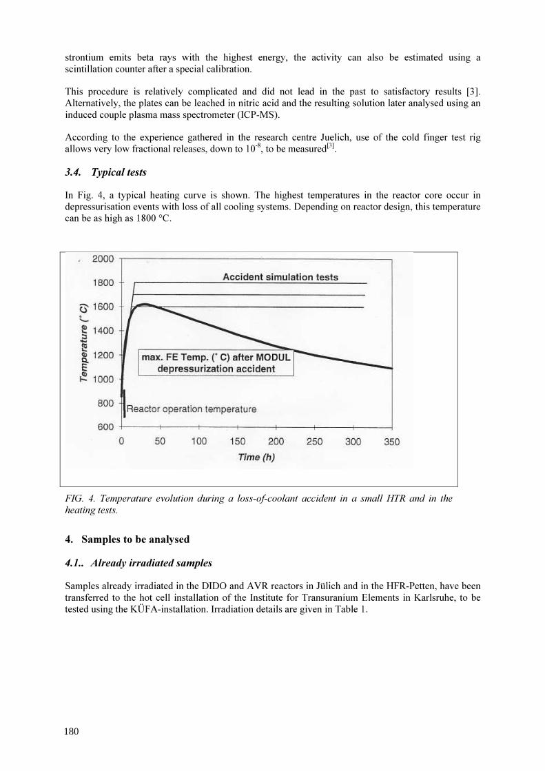
strontium emits beta rays with the highest energy, the activity can also be estimated using a scintillation counter after a special calibration. This procedure is relatively complicated and did not lead in the past to satisfactory results [3]. Alternatively, the plates can be leached in nitric acid and the resulting solution later analysed using an induced couple plasma mass spectrometer (ICP-MS). According to the experience gathered in the research centre Juelich, use of the cold finger test rig allows very low fractional releases, down to 10-8, to be measured[3]. 3.4. Typical tests In Fig. 4, a typical heating curve is shown. The highest temperatures in the reactor core occur in depressurisation events with loss of all cooling systems. Depending on reactor design, this temperature can be as high as 1800 °C.
FIG. 4. Temperature evolution during a loss-of-coolant accident in a small HTR and in the heating tests. 4. Samples to be analysed 4.1.. Already irradiated samples Samples already irradiated in the DIDO and AVR reactors in Jülich and in the HFR-Petten, have been transferred to the hot cell installation of the Institute for Transuranium Elements in Karlsruhe, to be tested using the KÜFA-installation. Irradiation details are given in Table 1.
180

TABLE 2. FUEL ELEMENTS TRANSFERRED FROM FZJ TO ITU-KARLSRUHE Sample No
Type Fuel Element No
Enrichment [%]
End of Irrad.
Burnup [% FIMA]
Fluence [1025m-2]
1 HFR-K5 1 10.6 16.05.94 6.7 4.0 2 2 10.6 8.8 5.8 3 3 10.6 9.1 5.9 4 4 10.6 8.7 4.9 5 HFR/K6 1 10.6 04.05.93 7.2 3.2 6 2 10.6 9.3 4.6 7 3 10.6 9.7 4.8 8 4 10.6 9.2 4.5 9 FRJ2-K15 1 16.76 11.11.90 14.06 0.2 10 2 16.76 15.27 0.2 11 3 16.76 14.76 0.1 12 AVR-
GLE 3 74/16 9.82 08.02.85 3.2 0.5
13 74/18 9.82 4.8 0.8 14 73/21 9.82 07.02.84 2.5 0.3 15 73/23 9.82 2.7 0.3 16 AVR-
GLE 4 73/22 16.76 07.02.84 3.4 0.3
17 87/6 16.76 19.11.88 3.51 0.3 18 87/7 16.76 3.53 0.3 19 87/8 16.76 3.53 0.3 20 87/9 16.76 3.56 0.3 21 87/10 16.76 3.51 0.3
4.2.. Samples to be irradiated in Petten In the second part of the project, samples will be irradiated in the High Flux Reactor of Petten. To this goal, pebbles containing TRISO-particles fabricated by NUKEM and compacts from USA-production will be irradiated up to a burnup of max. 20 % FIMA. In Table 2, the main characteristics of these pebbles are presented. TABLE 3. PEBBLES FROM LATEST GERMAN PRODUCTION TO BE IRRADIATED IN HFR
Coated particles
Kernel composition UO2
Kernel diameter 502 µm Enrichment 16.7 wt % Coating thicknesses
Buffer 92 µm Inner PyC 41 µm SiC 36 µm Outer PyC 40 µm Fuel Element
Number of cp 9 560 Volume packing fraction 6.2 % Matrix density 1.75 g/cm3
181

5. Conclusions Existing equipment, developed at the FZJ and designed to perform the PIE of HTR-fuel elements, was upgraded and modified for the installation in the hot cells of the ITU in a EU programme. The cold testing of the device has been performed and the hot installation has been completed. After installation, several samples irradiated in the AVR-Reactor and DIDO reactor in Germany as well as in the HFR-Petten will be tested in the framework of the European programme. Additional samples will be irradiated in the Petten-reactor to ultra-high burn-up and subsequently tested in KÜFA-device. Testing will start soon.
REFERENCES [1] SCHENK, W., Nachbestrahlungsausheizverfahren für Kugelbrennelemente und andere
Brennstoffproben, FZJ JUEL Report 1454, July 1977. [2] SCHENK, W., PITZER, D., NABIELEK, H., Fission Product Release Profiles from
Spherical HTR Fuel Elements at Accident Temperatures, FZJ JUEL Report 2234, September 1988.
[3] SCHENK, W., GONTARD, R., NABIELEK, H.,Performance of HTR Fuel Samples under High-Irradiation and Accident Simulation Conditions, with Emphasis on Test Capsules HFR-P4 and SL-P1, FZJ JUEL Report 3373, April 1997.
182

Prediction of metallic fission product release behavior in the 220 Mw(TH) FAPIG-HTGR during normal operation and core heatup accident
K. Verfonderna, H. Mikamib, F. Okamotob a b Research Center Juelich, Juelich, Germany, Fuji Electric Systems Co., Ltd., Kawasaki, Japan
Abstract. The FAPIG-HTGR presented at GENES4/ANP2003 by Fuji Electric is designed as a small modular 220 MW(th) direct cycle pebble bed high-temperature reactor for electricity production of 100 MW. The objective of this study is a first approach to assessing the metallic fission product release behavior in the core of the FAPIG-HTGR using the methodology that was developed and recommended at FZJ. The computer codes FRESCO and PANAMA were applied to assess the release of the radiologically relevant fission products Cs-137, 90Sr, and 110Agm from the FAPIG-HTGR during the fuel lifetime under normal operation and core heatup accident conditions. For the specified operating conditions of the reactor design considered and for the typical German reference spherical fuel element, the results show that under the given thermal hydraulic boundary conditions, the release remains on a very low level for all radionuclides investigated. For cesium, the dominant release is from defective/failed particles even for accident temperatures. The release of strontium remains always insignificant due to its enormous retention capability in matrix and kernel material. Silver release is low during normal operation similar to cesium, but shows significant release, even from intact coated particles under the conditions of elevated temperatures during the core heatup accident. From the perspective of these low metallic fission product release results, the FAPIG-HTGR can be judged to have a safe design that can be maintained easily.
1. Introduction In Japan, the “First atomic power industry group” (FAPIG)has started a feasibility study for a commercial, small modular high temperature reactor, the FAPIG-HTGR. Its concept aims at an electric power generation of 100 MW per unit, low construction cost of < 1200 $/kW(e), and sufficient inherent safety such that no evacuation is necessary even in the case of hypothetical accidents [1]. The objective of this study is a first approach to assessing the fission product release behavior in the core of the FAPIG-HTGR using the German computer codes FRESCO and PANAMA. The analysis for this study was conducted on the basis of the procedure recommended in Germany and described in [2]. A deterministic safety evaluation would require a more comprehensive analysis in terms of fuel performance, uncertainty ranges, and consideration of the complete release paths into the environment. 2. FAPIG-HTGR plant concept The FAPIG-HTGR presented by Fuji Electric [1] is designed as a small modular 220 MW(th) direct cycle gas turbine pebble bed reactor with the standard plant consisting of four units. The high thermal efficiency of 46% allows for an electricity production of 100 MW. A vertical cross section of the reactor system is shown in Fig. 1; its major specifications are summarized in Table 1. The pebble bed core of the FAPIG-HTGR has a diameter of 3 meter and a height of 11 meters. A multi-pass fuel loading scheme has been selected distinguishing two core regions. Fresher fuel with a larger thermal power will be loaded to the outer core, while more aged fuel with a smaller power production will be loaded to the inner core. The average power density is 2.6 MW/m3.
183
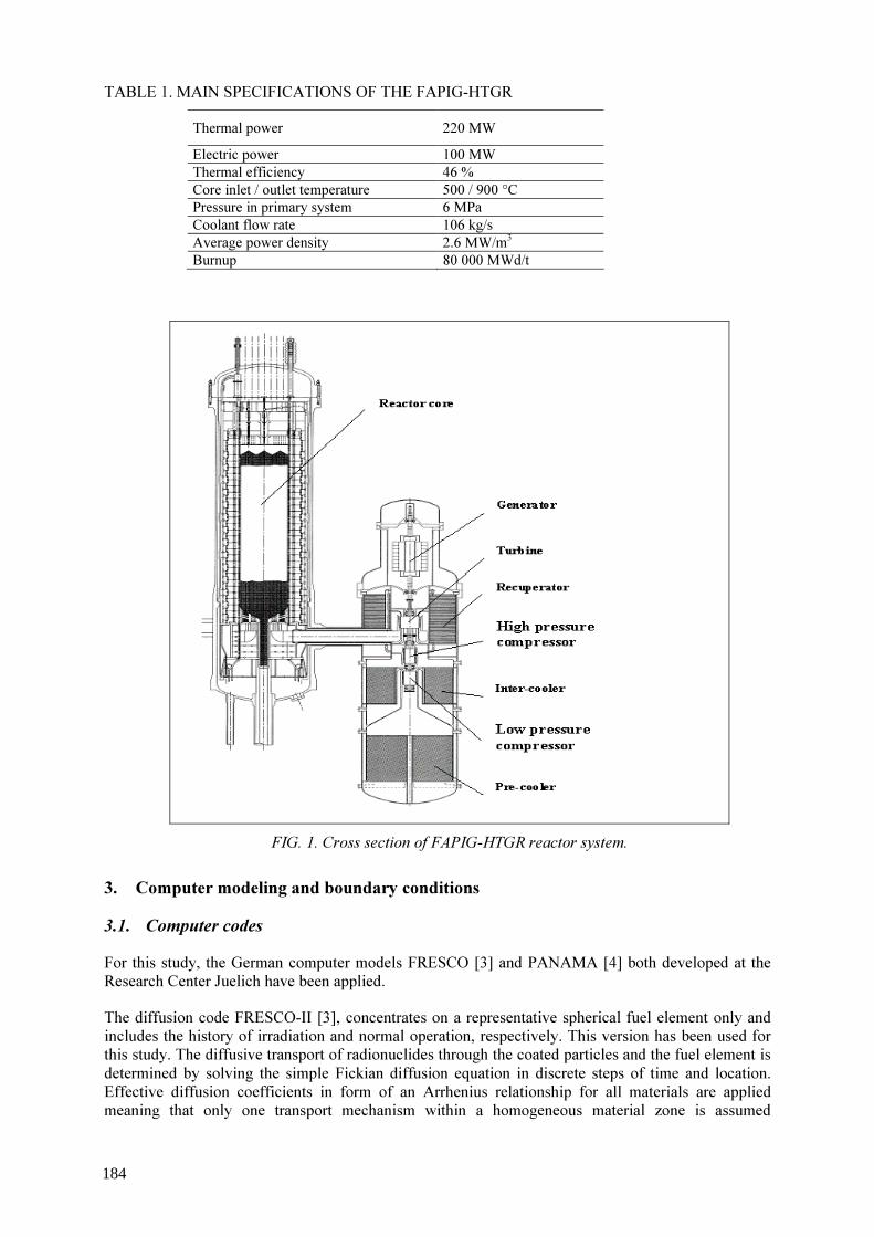
TABLE 1. MAIN SPECIFICATIONS OF THE FAPIG-HTGR Thermal power 220 MW Electric power 100 MW Thermal efficiency 46 % Core inlet / outlet temperature 500 / 900 °C Pressure in primary system 6 MPa Coolant flow rate 106 kg/s Average power density 2.6 MW/m3 Burnup 80 000 MWd/t
FIG. 1. Cross section of FAPIG-HTGR reactor system.
3. Computer modeling and boundary conditions 3.1. Computer codes For this study, the German computer models FRESCO [3] and PANAMA [4] both developed at the Research Center Juelich have been applied. The diffusion code FRESCO-II [3], concentrates on a representative spherical fuel element only and includes the history of irradiation and normal operation, respectively. This version has been used for this study. The diffusive transport of radionuclides through the coated particles and the fuel element is determined by solving the simple Fickian diffusion equation in discrete steps of time and location. Effective diffusion coefficients in form of an Arrhenius relationship for all materials are applied meaning that only one transport mechanism within a homogeneous material zone is assumed
184
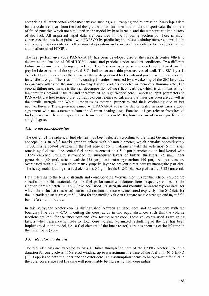
comprising all other conceivable mechanisms such as, e.g., trapping and re-emission. Main input data for the code are, apart from the fuel design, the initial fuel distribution, the transport data, the amount of failed particles which are simulated in the model by bare kernels, and the temperature-time history of the fuel. All important input data are described in the following Section 3. There is much experience that has been gained with FRESCO by predicting and postcalculating numerous irradiation and heating experiments as well as normal operation and core heatup accidents for designs of small and medium sized HTGRs. The fuel performance code PANAMA [4] has been developed also at the research center Jülich to determine the fraction of failed TRISO coated fuel particles under accident conditions. Two different failure mechanisms are being considered. The first one is a pressure vessel model based on the physical description of the spherical SiC shell to act as a thin pressure vessel wall. The SiC layer is expected to fail as soon as the stress on the coating caused by the internal gas pressure has exceeded its tensile strength. The stress on the coating is further increased by a weakening of the SiC layer due to corrosive attack on the inner surface by fission products modeled in form of a thinning rate. The second failure mechanism is thermal decomposition of the silicon carbide, which is dominant at high temperatures beyond 2000 °C and therefore of no significance here. Important input parameters to PANAMA are fuel temperature, burnup, oxygen release to calculate the inner gas pressure as well as the tensile strength and Weibull modulus as material properties and their weakening due to fast neutron fluence. The experience gained with PANAMA so far has demonstrated in most cases a good agreement with measurements from the German heating tests. Fractions of gas release from heated fuel spheres, which were exposed to extreme conditions in MTRs, however, are often overpredicted to a high degree. 3.2. Fuel characteristics The design of the spherical fuel element has been selected according to the latest German reference concept. It is an A3-3 matrix graphite sphere with 60 mm diameter, which contains approximately 11 000 fissile coated particles in the fuel zone of 55 mm diameter with the outermost 5 mm shell remaining fuel-free. The coated fuel particles consist of a 500 µm diameter oxide fuel kernel with 10.6% enriched uranium surrounded by subsequent layers of buffer (thickness: 95 µm), inner pyrocarbon (40 µm), silicon carbide (35 µm), and outer pyrocarbon (40 µm). All particles are overcoated with a 200 µm thick matrix graphite layer to prevent direct contact among the particles. The heavy metal loading of a fuel element is 0.5 g of fissile U-235 plus 6.5 g of fertile U-238 material. Data referring to the tensile strength and corresponding Weibull modulus for the silicon carbide are specific to the SiC material. For the fuel performance calculations here, respective values for the German particle batch EO 1607 have been used. Its strength and modulus represent typical data, for which the influence (decrease) due to fast neutron fluence was measured explicitly. The SiC data for the unirradiated state are σo = 834 MPa for the median value of ultimate tensile strength and mo = 8.02 for the Weibull modulus. In this study, the reactor core is distinguished between an inner core and an outer core with the boundary line at r = 0.75 m cutting the core radius in two equal distances such that the volume fractions are 25% for the inner core and 75% for the outer core. These values are used as weighing factors when reference is made to ‘total core’ values. No mixed reshuffling of the fuel has been implemented in the model, i.e., a fuel element of the inner (outer) core has spent its entire lifetime in the inner (outer) core. 3.3. Reactor conditions The fuel elements are expected to pass 12 times through the core of the FAPIG reactor. The time duration for one cycle is 116.8 efpd winding up to a maximum life time of the fuel of 1401.6 EFPD [1]. It applies to both the inner and the outer core. This assumption seems to be optimistic for fuel in the outer core, since fuel life time will presumably be increasing with core radius.
185
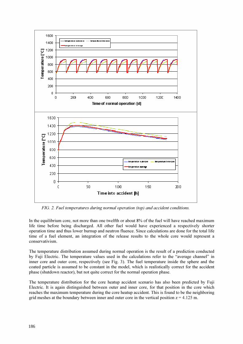
FIG. 2. Fuel temperatures during normal operation (top) and accident conditions.
In the equilibrium core, not more than one twelfth or about 8% of the fuel will have reached maximum life time before being discharged. All other fuel would have experienced a respectively shorter operation time and thus lower burnup and neutron fluence. Since calculations are done for the total life time of a fuel element, an integration of the release results to the whole core would represent a conservativism. The temperature distribution assumed during normal operation is the result of a prediction conducted by Fuji Electric. The temperature values used in the calculations refer to the “average channel” in inner core and outer core, respectively (see Fig. 3). The fuel temperature inside the sphere and the coated particle is assumed to be constant in the model, which is realistically correct for the accident phase (shutdown reactor), but not quite correct for the normal operation phase. The temperature distribution for the core heatup accident scenario has also been predicted by Fuji Electric. It is again distinguished between outer and inner core, for that position in the core which reaches the maximum temperature during the core heatup accident. This is found to be the neighboring grid meshes at the boundary between inner and outer core in the vertical position z = 4.125 m.
186

3.4. Initial fuel distribution and fission product inventories By far most of the fissile material is concentrated in the particle kernels surrounded by an intact coating. The particles are homogeneously dispersed in the fuel zone of the spherical fuel element. However, there are small fractions of uranium outside the kernel in the coating and matrix graphite due to the manufacturing process or natural contamination, respectively. The data given in Table 2 are typical to the German reference fuel element and have been used in the calculations. TABLE 2. URANIUM INVENTORIES OUTSIDE THE FUEL KERNELS
Uranium outside fuel kernel Inventory Fraction U in buffer 1.0x10⁻³ U in IPyC 1.0x10⁻⁴ U in SiC 1.0x10⁻⁶ U in OPyC 1.0x10⁻⁶ U in matrix graphite 1.0x10⁻⁷
A FRESCO calculation is conducted based on fractional data related to a “total inventory”. During the normal operation phase, inventory is built up according to the decay constant of the considered species until reaching 100% at the end of irradiation and beginning of the accident phase, respectively. 3.5. Particle failure fraction The FRESCO diffusion model distinguishes between two types of particles, intact particles and defective or failed particles. Intact particles have a complete and intact coating with fission products being transported through all single layers based on specified diffusion data. Defective or failed particles consist of a particle kernel only so that fission products are released from the kernel into the matrix graphite immediately. At the moment of failure of a particle, fission product contents inside the coating layers is considered to be released into the matrix graphite, while for the inventory still remaining in the kernel, it is ‘time-zero’, from which an independent diffusive release calculation is starting. There are usually three contributions to the fuel particle defect or failure fraction: (a) Manufacture-induced defects, which are existing from the beginning of fuel life and which
typically represent the first step of the failure function. The value representative for the German reference fuel is 3x10⁻⁵;
(b) Irradiation-induced failures, which occur during normal operation. The end-of-life value of 2*10-5 is representative for German fuel derived from a statistical evaluation of the present experience with modern German TRISO fuel. This value is used regardless of reactor operating conditions or fuel position in the core. For the study here, an increase of the failure fraction in 6 steps starting at a level of 3x10⁻⁵ and ending at the level of 5x10⁻⁵ was assumed. Step size is 4x10⁻⁶, step length is 233.6 efpd (or two cycles) except for the first and the final step, which are 116.8 EFPD. This simulates a linear increase in the failure fraction, which is conservative since typically an exponential growth of the failure fraction would be expected;
(c) Aaccident-induced failures that occur at elevated temperatures during heatup accidents. These failure fractions as a function of accident time and accident temperature have been estimated by applying the PANAMA model. The obtained failure curves have then been translated into 4 more steps to complete the step function.
3.6. Transport data The diffusion coefficients of the different fission product species in the various fuel materials have been chosen according to the German recommendations [2]. As already mentioned above, the sorption
187

effect on cooler graphite has been neglected in this study, rather assuming an unhindered release from the fuel element surface into the coolant. 4. Results 4.1. Fission product release behavior during normal operation 4.1.1. Fuel particle performance The fast neutron fluence is responsible for a degradation of the tensile strength of the silicon carbide layer. This functional relationship (see [4]) leads in the case considered here to a reduction of the tensile strength by about 10% compared to unirradiated SiC as given in the following Table 3. TABLE 3. DEGRADATION OF SIC PROPERTIES DUE TO FAST NEUTRON FLUENCE
Silicon Carbide Before Irradiation Irradiated with 2.4x1025 m-2, E>0.1MeV
Median Tensile Strength [MPa] 834 760 Weibull Modulus 8.02 6.98
The CO production in the UO2 kernel contributing to the pressure inside the particle is strongly dependent on the temperature-time history during normal operation. Considering the transient relationship of the temperature cycles here, the stepwise accumulation of the CO release results in a number of oxygen atoms per fission (O/F) at the end of the normal operation phase of O / F = 0.01838. This value can be used to calculate back to an average irradiation temperature of Tirr = 814 °C, meaning that this temperature, if assumed constant throughout the whole normal operation phase, would have resulted in the same amount of oxygen production. 4.1.2. Metallic fission product release The calculations of fission product release during normal operation have been conducted for the radiologically relevant isotopes Cs-137, Sr-90, and Ag-110m. Furthermore it was distinguished between inner and outer core; the results of both calculations are then combined to “total core” data by applying the above mentioned volume-related weighing factors. Figure 3 summarizes all curves of release from the coated particles (thin lines) and from the fuel element (thick lines) of Cs-137, Sr-90, and Ag-110m during normal operation. Since for normal operation, the “outer core” curve is always the higher one, above the average curve, because of the higher temperatures, the dominant contribution to the total core release will come from the outer core. The wavy shape of the release curves reflects the temperature cycles of the passes through the core during the lifetime of the fuel. It is the result of the combined effects of decay, diffusion, and inventory buildup. For the long-lived isotopes (137Cs, 90Sr), the buildup of the inventory is nearly linear. Diffusive release is highest in the second half of either cycle and bottom half of the core, respectively, when temperatures are highest. The cesium release curves are steadily increasing, but stay below the fraction of failed particles during the whole lifetime of the fuel. End-of-life release from the coated particles is 1.8x10⁻⁵, thus 60% of the inventory of the failed particles. For the given “low” fuel temperatures, particles with an intact coating are not expected to contribute to the cesium release.
188

1 E-10
1 E-9
1 E-8
1 E-7
1 E-6
1 E-5
1 E-4
1 E-3
1 E-2
0 200 400 600 800 1000 1200 1400Time of normal operation [d]
Frac
tion
silver release from cp silver release from festrontium release from cp strontium release from fecesium release from cp cesium release from fe
The release of strontium is smaller compared to cesium both from the coated particles and the fuel element. Due to a low diffusion coefficient in the kernel material UO2 at normal operation temperatures, there is hardly any strontium escaping the place of its origin, even for defective or failed particles. In addition, a similarly slow diffusive transport of strontium through matrix graphite reduces the release from the fuel element into the coolant down to insignificant values. Silver shows a similar release behavior as cesium. Both species are in the same range of release from coated particles and from the fuel element. Towards the end of life of the fuel, silver appears to show the higher release rates. Still there are some interesting differences. The waves in the silver curves are somewhat more pronounced resulting from the stronger decay of the Ag-110m compared to the long-lived cesium isotope. The fractional release of silver from the particles in the inner core, i.e., at lower temperatures, is even continuously decreasing after 400 days showing that diffusive release towards the end of a cycle cannot compensate for the decay. This is in contrast to the release from outer core particles. TABLE 4. FRACTIONAL RELEASE FROM THE TOTAL CORE AT END OF LIFE (EOL) OF THE FUEL
Fractional release from Outer Core Inner Core Total Core
Cs-137 Particle kernels 3.50x10⁻¹ 1.97x10⁻¹ 3.12x10⁻¹ Intact coated particles 4.22x10⁻⁷ 2.30x10⁻⁷ 3.74x10⁻⁷ Defective/failed coated particles 2.04x10⁻⁵ 1.08x10⁻⁵ 1.80x10⁻⁵ Coated particles 2.08x10⁻⁵ 1.10x10⁻⁵ 1.84x10⁻⁵ Fuel element 8.09x10⁻⁶ 1.38x10⁻⁶ 6.41x10⁻⁶ Sr-90 Particle kernels 1.54x10⁻⁷ 6.70x10⁻⁹ 1.17x10⁻⁷ Intact coated particles 1.60x10⁻⁶ 1.08x10⁻⁶ 1.47x10⁻⁶ Defective/failed coated particles 1.08x10⁻⁸ 1.08x10⁻⁸ 1.08x10⁻⁸ Coated particles 1.61x10⁻⁶ 1.09x10⁻⁶ 1.48x10⁻⁶ Fuel element 1.09x10⁻⁹ 2.31x10⁻¹⁰ 8.76x10⁻¹⁰ Fractional release from Outer Core Inner Core Total Core Ag-110m
FIG. 3. Fractional release of metallic fission products during normal operation.
189

Particle kernels 5.68x10⁻¹ 4.18x10⁻¹ 5.31x10⁻¹ Intact coated particles 2.93x10⁻⁵ 9.64x10⁻⁷ 2.22x10⁻⁵ Defective/failed coated particles 2.63x10⁻⁶ 1.92x10⁻⁶ 2.45x10⁻⁶ Coated particles 3.19x10⁻⁵ 2.88x10⁻⁶ 2.47x10⁻⁵ Fuel element 1.58x10⁻⁵ 6.13x10⁻⁷ 1.20x10⁻⁵
Another difference are the sharp, step-like increases of release from the particles at the moments, when also the number of failed particles has increased in a step according to the particle failure step function defined before. These transitions are much more smoothed in the respective cesium release curves. Reason for this difference is the diffusion coefficient in the UO2 kernel, which is highest for silver over the whole temperature range considered here. It means that more silver has migrated from the kernels into the coating layers, resulting in a sharp release step when, according to an assumption in the FRESCO model, the inventory in the total coating is liberated immediately upon the failure of a particle. It confirms again that under the given temperature conditions, the release behavior of cesium and silver is very similar, the respective curves being in a fairly narrow range over the whole fuel life time. End-of-life fractional release values are given in the following Table 4. The table provides also release data from the particle kernels and the release from the particles distinguished between defective/failed and intact particles. Particle kernels have released more than 50% of their silver inventory at EOL of the fuel; the fraction for cesium is about 30%, while for strontium, the release fraction is negligible. Furthermore, the release of cesium is practically from defective/failed particles only corresponding to 36% of their inventory (‘total core’). 4.2. Metallic fission product release during core heatup accident It should be stressed that, unlike the normal operation phase, fuel temperatures during the core heatup accident phase are higher in the inner core than in the outer core.
1 E-8
1 E-7
1 E-6
1 E-5
1 E-4
1 E-3
1 E-2
1 E-1
1 E+0
0 50 100 150 200Time into accident [h]
Frac
tion
cp failure outercore cp failure innercore
cp failure totalcore gasrelease totalcore
PANAMA
FIG. 4. Failure probability of and gas release from EOL coated particles during core heatup accident scenario.
190

4.2.1. Fuel performance The probability for a failure of particles exposed to maximum irradiation conditions reaching a burnup of 9% FIMA and a fast neutron fluence of 2.4x1025 m-2, E>0.1 MeV (which was defined to be the maximum nominal fast fluence for the SIEMENS HTR-Module design) in 12 cycles through the reactor during the core heatup accident scenario is plotted in Fig. 4-5. The diagram shows both the single curves representing the inner (upper curve) and outer core (lower curve), as well as the resulting failure curve for the total core (thick blue line) plus the curve for the concomitant release of gaseous fission products (thick red line). Since the maximum fast neutron fluence of 2.4x1025 m-2, E>0.1MeV, has been assumed valid for both inner and outer core, SiC tensile strength degradation is the same for all. These particle failure calculations for the inner and outer core during the accident phase have been conducted as a preparatory step to derive the additional steps of the failure function for the FRESCO-II calculations. The results of particle failure and during the core heatup accident based on PANAMA calculations are shown in Fig. 4 distinguishing between the inner and the outer reactor core. Even for the assumed maximum conditions of burnup, fast fluence and accident temperatures, the accident-induced particle failure fraction does not reach the level of one failed particle. 4.2.2. Fission product release The integral fractional release curves for the total core are given in Fig. 5 for all three fission product species investigated. The comparison exhibits the release sequence typically expected under elevated temperature conditions and often observed with silver being released most, followed by cesium and strontium. According to the given temperature boundary condition, the release from the outer core is higher than from the inner core at the beginning as a result of normal operation release behavior. Since accident temperatures are higher in the inner core, the release curves for the inner core soon increase such that they eventually intersect the respective curves for the outer core.
FIG. 5. Fractional release of metallic fission products during core heatup accident.
1 E-10
1 E-9
1 E-8
1 E-7
1 E-6
1 E-5
1 E-4
1 E-3
1 E-2
0 50 100 150 200Time into accident [h]
Frac
tion
silver release from cp silver release from festrontium release from cp strontium release from fecesium release from cp cesium release from fe
191

The two thick curves represent the total core and are mainly dominated by the release from the outer core. The curves of release from the particles approach, but do not exceed the fraction of failed particles showing that even under the conditions of elevated temperatures, the cesium release is mainly from the failed particles and not from the intact particles (see also Table 4-3). The release of strontium from the fuel element during the core heatup accident remains again on a low level due to a very efficient retention in the matrix graphite even for the accident temperatures. With respect to the fractional release curves for Ag-110m during the accident conditions, silver release soon exceeds the fraction of failed particles (thin green line) revealing that it is significantly released from intact particles also. The release curves for the particles (blue) are very close to the corresponding curves for the fuel element (red) showing that there is a rapid transport of silver through matrix graphite, i.e., practically no buffer effect of the matrix, at elevated temperatures. Also the retention capability of the matrix graphite can be seen directly given by the difference between release from the particles (thin lines) and release from the fuel element (thick lines). The inventory in the matrix is lowest for silver (9% of the amount released from the particles) and largest for strontium (~100%) with cesium somewhere in between (40%). The percentage data are valid for the moment 180 h. The obtained release values after 180 h into the core heatup accident are listed in Table 5. TABLE 5. FRACTIONAL RELEASE FROM THE TOTAL CORE AFTER 180 H OF CORE HEATUP ACCIDENT
Fractional release from Outer Core Inner Core Total Core Cs-137 Particle kernels 5.59x10⁻¹ 6.50x10⁻¹ 5.82x10⁻¹ Intact coated particles 5.52x10⁻⁷ 7.17x10⁻⁷ 5.93x10⁻⁷ Defective/failed coated particles 4.85x10⁻⁵ 4.88x10⁻⁵ 4.86x10⁻⁵ Coated particles 4.90x10⁻⁵ 4.96x10⁻⁵ 4.91x10⁻⁵ Fuel element 2.70x10⁻⁵ 3.75x10⁻⁵ 2.9610-5 Sr-90 Particle kernels 3.93x10⁻⁴ 2.73x10⁻³ 9.77x10⁻⁴ Intact coated particles 8.49x10⁻⁶ 3.98x10⁻⁵ 1.63x10⁻⁵ Defective/failed coated particles 3.81x10⁻⁸ 3.04x10⁻⁸ 3.71x10⁻⁸ Coated particles 8.53x10⁻⁶ 3.99x10⁻⁵ 1.64x10⁻⁵ Fuel element 7.29x10⁻⁹ 1.40x10⁻⁸ 8.96x10⁻⁹ Ag-110m Particle kernels 7.27x10⁻¹ 7.53x10⁻¹ 7.34x10⁻¹ Intact coated particles 3.79x10⁻³ 2.07x10⁻² 8.02x10⁻³ Defective/failed coated particles 1.60x10⁻⁵ 6.92x10⁻⁶ 1.37x10⁻⁵ Coated particles 3.81x10⁻³ 2.07x10⁻² 8.03x10⁻³ Fuel element 3.20x10⁻³ 1.95x10⁻² 7.28x10⁻³
Even under accident conditions, cesium release is mainly from the defective/failed particles. This is in contrast to the silver release behavior, where the intact particles are the dominant contributor to release. In terms of release from the particle kernels, the silver fraction outside the kernels is 73%, for cesium 58%. For strontium, in comparison to normal operation, the release fraction from the kernels has increased by several orders of magnitude up to 0.1%, but still is comparatively low. 5. Summary The objective of this study was to give an example for the procedure of fission product release behavior analysis using the German computer codes FRESCO and PANAMA. These models were applied to assess the release of the radiologically relevant fission products Cs-137, Sr-90, and Ag-
192
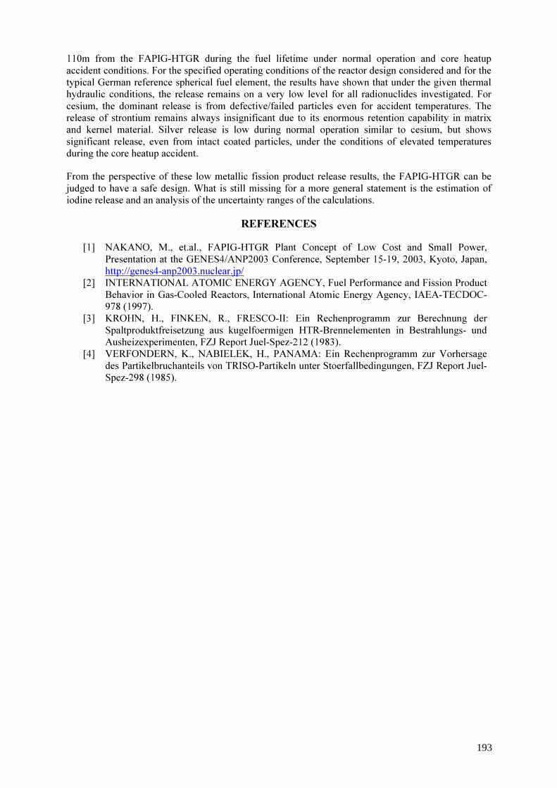
110m from the FAPIG-HTGR during the fuel lifetime under normal operation and core heatup accident conditions. For the specified operating conditions of the reactor design considered and for the typical German reference spherical fuel element, the results have shown that under the given thermal hydraulic conditions, the release remains on a very low level for all radionuclides investigated. For cesium, the dominant release is from defective/failed particles even for accident temperatures. The release of strontium remains always insignificant due to its enormous retention capability in matrix and kernel material. Silver release is low during normal operation similar to cesium, but shows significant release, even from intact coated particles, under the conditions of elevated temperatures during the core heatup accident. From the perspective of these low metallic fission product release results, the FAPIG-HTGR can be judged to have a safe design. What is still missing for a more general statement is the estimation of iodine release and an analysis of the uncertainty ranges of the calculations.
REFERENCES [1] NAKANO, M., et.al., FAPIG-HTGR Plant Concept of Low Cost and Small Power,
Presentation at the GENES4/ANP2003 Conference, September 15-19, 2003, Kyoto, Japan, http://genes4-anp2003.nuclear.jp/
[2] INTERNATIONAL ATOMIC ENERGY AGENCY, Fuel Performance and Fission Product Behavior in Gas-Cooled Reactors, International Atomic Energy Agency, IAEA-TECDOC-978 (1997).
[3] KROHN, H., FINKEN, R., FRESCO-II: Ein Rechenprogramm zur Berechnung der Spaltproduktfreisetzung aus kugelfoermigen HTR-Brennelementen in Bestrahlungs- und Ausheizexperimenten, FZJ Report Juel-Spez-212 (1983).
[4] VERFONDERN, K., NABIELEK, H., PANAMA: Ein Rechenprogramm zur Vorhersage des Partikelbruchanteils von TRISO-Partikeln unter Stoerfallbedingungen, FZJ Report Juel-Spez-298 (1985).
193

TRISO-coated particle fuel phenomenon identification and ranking tables (PIRTS) for fission product transport due to manufacturing, operations and accidents
S.D. Rubin United States Nuclear Regulatory Commission US-NRC, USA
Abstract. In anticipation of future licensing applications for gas-cooled reactors, the United States Nuclear Regulatory Commission (NRC) seeks to fully understand the significant features of TRISO-coated particle fuel design, manufacture, and operation, as well as behaviour during accidents. To address this objective, the NRC commissioned the formation of a panel of experts to identify and rank the factors, characteristics, and phenomena associated with the life-cycle phases of TRISO-coated particle fuel. Six phenomena identification and ranking tables were developed by the panel and are presented in this report. They are: (1) Manufacturing, (2) Operations, (3) Depressurized Heatup Accident, (4) Reactivity Accident, (5) Depressurization Accident with Water Ingress, and (6) Depressurization Accident with Air Ingress. Analyses and summaries for each of the six ‘phenomena identification and ranking tables’ (PIRTs) are presented in the panel’s report. A total of 327 factors, characteristics and phenomena are identified in the six PIRT tables. The importance of each factor, characteristic, process or phenomenon was assessed relative to the magnitude of its influence on fission product release or in a more accident consequence-related term, the source term. One hundred-ten factors, characteristics and phenomena were assigned an importance rank of “High” by each panel member. The panel concluded that these 110 factors, characteristics and phenomena had the most significant impact on fission product release. Each panel member prepared a written rationale supporting the importance rank assigned to each highly ranked factor, characteristic or phenomenon. These rationales are included. The level of knowledge for each factor, characteristic or phenomenon was also assessed and documented. Of particular interest are those factors, characteristics or phenomena assessed by the panel as being of high importance but not yet adequately understood. The PIRT results will be used by the agency to: (1) identify key attributes of gas-cooled reactor fuel manufacture which may require regulatory oversight; (2) provide a valuable reference for the review of vendor gas-cooled reactor fuel qualification plans (3) provide insights for developing plans for fuel safety margin testing; (4) assist in defining test data needs for the development of fuel performance and fission product transport models (5) inform decisions regarding the development of NRC's independent gas-cooled reactor fuel performance code and fission product transport models; (6) support the development of NRC’s independent models for source term calculations; and (7) provide insights for the review of vendor gas-cooled fuel safety analyses.
1. Introduction Most nuclear power reactors presently operating throughout the world are water-cooled. The core of these reactors consists of arrays of fuel bundles, each bundle containing a number of fuel pins. Each fuel pin contains a stack of cylindrical, ceramic UO2 fuel pellets contained within a sheath of metallic cladding. The fuel forms for gas-cooled reactors are very different. The TRISO-coated fuel particle is a spherical layered composite about 1 mm in diameter. It consists of a kernel of uranium dioxide surrounded by a porous graphite buffer layer. Surrounding the buffer layer are a layer of dense pyrolytic carbon, a SiC layer, and a dense outer pyrolytic carbon layer. These three isotropic layers are termed the TRISO coating. Thousands of these particles are combined with a matrix material and pressed into either spherical forms for pebble bed fuels or cylindrical or annular compacts for prismatic fuels. In anticipation of future licensing applications for gas-cooled reactors, the United States Nuclear Regulatory Commission (NRC) seeks to fully understand the significant features of TRISO-coated particle fuel design, manufacture, and operation, as well as behaviour during accidents. To address this
194

objective, the NRC has commissioned the formation of a panel of experts to identify and rank the factors, characteristics, and phenomena associated with the life-cycle phases of TRISO-coated particle fuel. The products of the panel are phenomena identification and ranking tables (PIRTs) and the associated documentation. 2. Objectives The objectives of the PIRT program on TRISO-coated particle fuel are to:
1. identify key attributes of gas-cooled reactor fuel manufacture which may require regulatory oversight;
2. provide a valuable reference for the review of vendor gas-cooled reactor fuel qualification plans; 3. provide insights for developing plans for fuel safety margin testing; 4. assist in defining test data needs for the development of fuel performance and fission product
transport models; 5. inform decisions regarding the development of NRC's independent gas-cooled reactor fuel
performance code and fission product transport models; 6. support the development of NRC’s independent models for source term calculations; and 7. provide insights for the review of vendor gas-cooled fuel safety analyses.
A three-member panel of experts developed the PIRTs presented in this document. The charter of this small PIRT panel was to develop TRISO-coated particle fuel PIRTs, i.e., structured PIRT tables and accompanying rationales. This report will be provided to international experts and other knowledgeable stakeholders for review and comment. The NRC will collect and compile the comments provided by the reviewers. The compiled peer review comments will be collected as a separate source of expert opinions on TRISO-coated particle fuel. Six PIRTs were developed by the panel and are presented in this document. They are:
1. Manufacturing; 2. Operations; 3. Depressurized heatup accident; 4. Reactivity initiated accident RIA; 5. Depressurization accident with water ingress; and 6. Depressurization accident with air ingress.
3. Report The full text with all Appendices is available in < http://www.nrc.gov/reading-rm/doc-collections/nuregs/contract/cr6844>. The general PIRT process is described in Section 1 as well as a detailed discussion of the application of the general process for the TRISO-coated particle fuel PIRT program. Section 2 presents an extensive discussion of the design function of each component of TRISO-coated particle fuel, i.e., the kernel, buffer layer, inner PyC layer, SiC layer, outer PyC layer, and the fuel element. Manufacturing practices, fuel particle performance throughout the operational life of the fuel and also under accident conditions, and fuel failure mechanisms are also discussed.
195
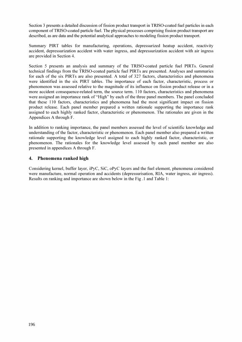
Section 3 presents a detailed discussion of fission product transport in TRISO-coated fuel particles in each component of TRISO-coated particle fuel. The physical processes comprising fission product transport are described, as are data and the potential analytical approaches to modeling fission product transport. Summary PIRT tables for manufacturing, operations, depressurized heatup accident, reactivity accident, depressurization accident with water ingress, and depressurization accident with air ingress are provided in Section 4. Section 5 presents an analysis and summary of the TRISO-coated particle fuel PIRTs. General technical findings from the TRISO-coated particle fuel PIRTs are presented. Analyses and summaries for each of the six PIRTs are also presented. A total of 327 factors, characteristics and phenomena were identified in the six PIRT tables. The importance of each factor, characteristic, process or phenomenon was assessed relative to the magnitude of its influence on fission product release or in a more accident consequence-related term, the source term. 110 factors, characteristics and phenomena were assigned an importance rank of “High” by each of the three panel members. The panel concluded that these 110 factors, characteristics and phenomena had the most significant impact on fission product release. Each panel member prepared a written rationale supporting the importance rank assigned to each highly ranked factor, characteristic or phenomenon. The rationales are given in the Appendices A through F. In addition to ranking importance, the panel members assessed the level of scientific knowledge and understanding of the factor, characteristic or phenomenon. Each panel member also prepared a written rationale supporting the knowledge level assigned to each highly ranked factor, characteristic, or phenomenon. The rationales for the knowledge level assessed by each panel member are also presented in appendices A through F. 4. Phenomena ranked high Considering kernel, buffer layer, iPyC, SiC, oPyC layers and the fuel element, phenomena considered were manufacture, normal operation and accidents (depressurisation, RIA, water ingress, air ingress). Results on ranking and importance are shown below in the Fig .1 and Table 1:
196

FIG. 1. Census of various safety-significant phenomena for GCR fuelled with coated particle fuel.
Manufacture
Operations
Depressuriz-ation accidentReactivity accident
Water ingress Accident Air Ingress Accident
Kernel
Buffer Layer
Inner PyC Layer
SiC Layer
Outer Layer
Fuel Element
0
1
2
3
4
5
6
7
Kernel
Buffer Layer
Inner PyC Layer
SiC Layer
Outer Layer
Fuel Element
ManufactureOperations
Depressuriz-ation accidentReactivity accident
Water ingress Accident Air Ingress Accident
Kernel
Buffer Layer
Inner PyC Layer
SiC Layer
Outer Layer
Fuel Element
0
1
2
3
4
5
6
7
KernelBuffer LayerInner PyC LayerSiC LayerOuter LayerFuel Element
197
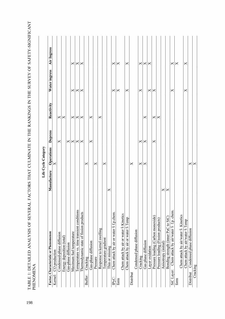
TABL
E 1:
DET
AIL
ED A
NA
LYSI
S O
F SE
VER
AL
FACT
ORS
TH
AT
CULM
INA
TE IN
TH
E RA
NK
ING
S IN
TH
E SU
RVEY
OF
SAFE
TY-S
IGN
IFIC
AN
T PH
ENO
MEN
A
Life C
ycle
Categ
ory
Facto
r, Ch
arac
terist
ic or
Phen
omen
on
Man
ufactu
re Op
eratio
ns De
press
Re
activi
ty W
ater i
ngres
s Ai
r Ing
ress
Kernel: CO
production
X
Conden
sed-ph
ase diffusion
X X
Energy deposition (to
tal)
X
Gas-phase diffusion
X
Maximu
m fuel temperature
X X
X X
Term
perature vs. tim
e transient con
ditions
X X
X X
Thermodynam
ic state o
f fission products
X X
X X
Buffer: C
racking
X
Gas-phase diffusion
X X
Pressure
X
Resp
onse to kernel sw
elling
X
Temperature gradient
X
Thin or missing
X
IPyC: C
hem attack by air o
r water Š f.p
.chem.
X X
form
Ch
em attack by air o
r water Š Kinetics
X X
Ch
em attack by air o
r water Š Te
mp
X X
Distribut
Conden
sed phase diffusion
X
Cracking
X
X
X X
Gas phase diffusion
X
X X
X
Laye
r oxidation
X X
Pressure lo
ading (Carbon monoxide)
X X
X
Pressure lo
ading (Fission products)
X
Anisotropy (initial)
X
Bonding strength (inner Pu
C to S
iC)
X
SiC La
yer: Ch
em attack by air/w
ater Š f.p. che
m.
X X
form
C
hem attack by air/w
ater Š Kinetics
X
C
hem attack by air/w
ater Š Te
mp
X X
Distribut Conden
sed phase diffusion
X
Crack
ing
X
198
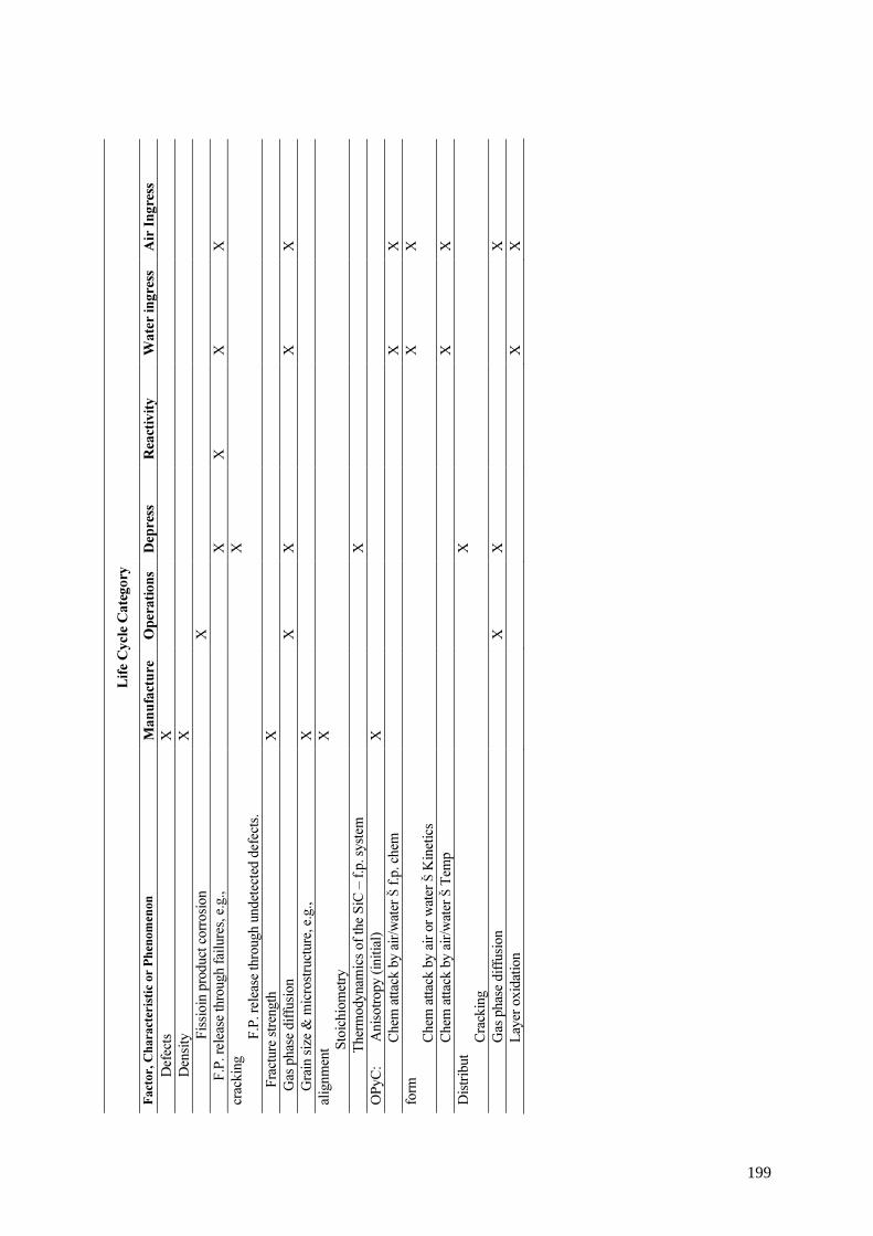
Life C
ycle
Categ
ory
Facto
r, Ch
arac
terist
ic or
Phen
omen
on
Man
ufactu
re Op
eratio
ns De
press
Re
activi
ty W
ater i
ngres
s Ai
r Ing
ress
Defects
X
Density
X
F
issioin prod
uct corrosion
X
F
.P. release through failures, e.g.,
X X
X X
cracking
F
.P. release through undetected defects.
X
Fracture streng
th X
Gas phas
e diffu
sion
X
X
X X
Grain siz
e & microstructure, e
.g.,
X
alignment
Sto
ichiom
etry
X
T
hermodynam
ics of the SiC – f.p. system
X
OPyC: Anisotropy (in
itial)
X
Chem
attack by air/w
ater Š f.p
. chem
X X
form
Chem
attack by air o
r water Š Kinetics
X X
Chem
attack by air/w
ater Š Te
mp
X X
Distribut
Cracking
X
Gas phase diffusion
X
X
X
Laye
r oxidation
X X
199

5. Pirt applications/ benefit/ plans Applications should help to focus the fuel fabrication regulatory oversight, to aid in review of vendor fuel qualification plans, to provide insights for fuel safety margin testing, to identify data needs for fuel performance and fission product transport models, to develop and review fuel performance models, to develop and review mechanistic source term models and to conduct and review fuel performance analyses. The benefit of the PIRT approach are the systematic structure and completeness that is auditable. The PIRT provides extensive content on what is important and what is not, the PIRT provides the rationale for ranking decisions on the basis of the current state of knowledge. This way, it adds to the credibility of HTR technology. Should US-NRC receive an application to license or certify an HTGR, the PIRT report will provide significant input to the NRC’s effort to develop an infrastructure of data, analytical codes, methods and expertise to effectively review fuel safety performance.
200

Post-irradiation examination of HTR-10 fuel
Tang Chunhea, Fu Xiaominga, Zhu Junguoa, K. Koshcheevb, A.V. Kozlovb, O.G. Karlovc, Y.G. Degaltsevc
a b
c
Institute of Nuclear Energy Technology, Tsinghua University, China Federal State Unitary Enterprise, Institute of Nuclear Materials, Zarechny, Sverdlovsk Region, Russian Federation
Russian Research Centre “Kurchatov Institute”, Moscow, Russian Federation Abstract. The irradiation test of 4 spherical fuel elements sampled randomly from the first and second production batches, which were produced for the 10 MW high temperature gas-cooled test reactor (HTR-10), ended in January 2003, in the Russian IVV-2M reactor. The post-irradiation examination started in February 2004, and contained visual inspection, dimension and weight measurement for the irradiated fuel elements, deconsolidation of the irradiated balls and determining the distribution of the solid fission products in the matrix graphite along the ball diameter, measuring the failure fraction of coated particles obtained from the ball deconsolidation by the irradiated microsphere gamma analyzer (IMGA), ceramographic examination of the failed and intact particles, and determining the distribution of the solid fission products in the coatings by chemical layer-by-layer analysis. Up to now, the visual inspection and dimension measurement of all the irradiated fuel elements, deconsolidation and determining the distribution of the solid fission products in the matrix graphite along the ball diameter, measuring the failure fraction of the loose coated fuel particles obtained from the ball deconsolidation by the IMGA for spherical fuel element No.12 (SFE12) in capsule 3 and SFE 7 in capsule 5 have been completed. SFE12 shows good irradiation performance, but the failure fraction of the coated fuel particles in SFE 7 is about 3% due to too high heating temperature in reactor.
1. Introduction The HTR-10 built in China is a modular pebble-bed type high temperature gas-cooled reactor. Spherical fuel elements (SFE) are employed in the pebble-bed core. The HTR-10 fuel element with 60 mm in diameter consists of the matrix graphite and 8300 coated fuel particles. The LEU (low enriched uranium) TRISO coated fuel particle is adopted in the HTR-10 program. It is composed of a central UO2 kernel of 500 µm in diameter and four layers, which are: (1) low density porous carbon buffer layer of 95µm in thickness; (2) an inner high-density isotropic PyC layer with 40µm thickness; (3) a 35µm thick SiC layer; and (4) an outer high-density isotropic PyC layer of 40µm thickness. The fabrication technology for HTR-10 fuel element has been established through R&D activities in the past 20 years in Institute of Nuclear Energy Technology, Tsinghua University (INET) [1,2]. Over 20 000 spherical fuel elements were produced for HTR-10 in 2000 and 2001. In order to assess the fabricated fuel performance, an in-pile irradiation test of 2 SFEs (SFE5 and SFE7) randomly sampled from the first product batch and another 2 fuel balls (SFE8 and SFE12) from the second batch was carried out in the Russian IVV-2M research reactor. This test started in July 2000, and ended in February 2003. The irradiation temperature is 1000 °C. The burnup of the irradiated 4 fuel elements reached 97 300; 107 000; 101 900 and 95 000 MWd/tU; respectively. Their fast neutron fluence reached 1.10x10²¹, 1.31x10²¹, 1.30x10²¹ and 1.06x10²¹n/cm2, respectively. During the irradiation test, the temperature of the fuel element in capsule 3 was increased to 1200 °C for 200 hours and 1250 °C for 200 hours, when its burnup reached 38 700 and 57 300 MWd/tU, respectively. At the end of the in-pile test, the high temperature heating testing of the fuel element in capsule 5 was carried out in the reactor. The fission gas release (R/B) as a function of the burnup is given in Fig.1. The release rate curves keep small fluctuations under average fuel temperature, ~1000 °C, due to the temperature fluctuation and
201
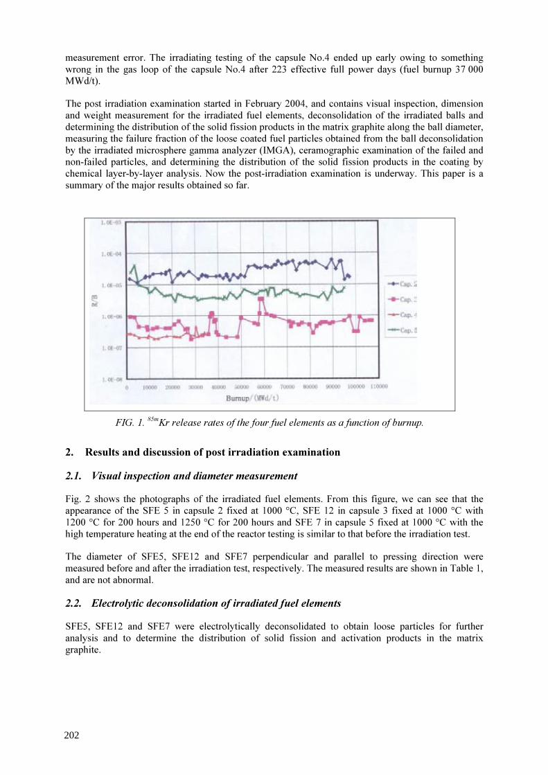
measurement error. The irradiating testing of the capsule No.4 ended up early owing to something wrong in the gas loop of the capsule No.4 after 223 effective full power days (fuel burnup 37 000 MWd/t). The post irradiation examination started in February 2004, and contains visual inspection, dimension and weight measurement for the irradiated fuel elements, deconsolidation of the irradiated balls and determining the distribution of the solid fission products in the matrix graphite along the ball diameter, measuring the failure fraction of the loose coated fuel particles obtained from the ball deconsolidation by the irradiated microsphere gamma analyzer (IMGA), ceramographic examination of the failed and non-failed particles, and determining the distribution of the solid fission products in the coating by chemical layer-by-layer analysis. Now the post-irradiation examination is underway. This paper is a summary of the major results obtained so far.
FIG. 1. 85mKr release rates of the four fuel elements as a function of burnup.
2. Results and discussion of post irradiation examination 2.1. Visual inspection and diameter measurement Fig. 2 shows the photographs of the irradiated fuel elements. From this figure, we can see that the appearance of the SFE 5 in capsule 2 fixed at 1000 °C, SFE 12 in capsule 3 fixed at 1000 °C with 1200 °C for 200 hours and 1250 °C for 200 hours and SFE 7 in capsule 5 fixed at 1000 °C with the high temperature heating at the end of the reactor testing is similar to that before the irradiation test. The diameter of SFE5, SFE12 and SFE7 perpendicular and parallel to pressing direction were measured before and after the irradiation test, respectively. The measured results are shown in Table 1, and are not abnormal. 2.2. Electrolytic deconsolidation of irradiated fuel elements SFE5, SFE12 and SFE7 were electrolytically deconsolidated to obtain loose particles for further analysis and to determine the distribution of solid fission and activation products in the matrix graphite.
202
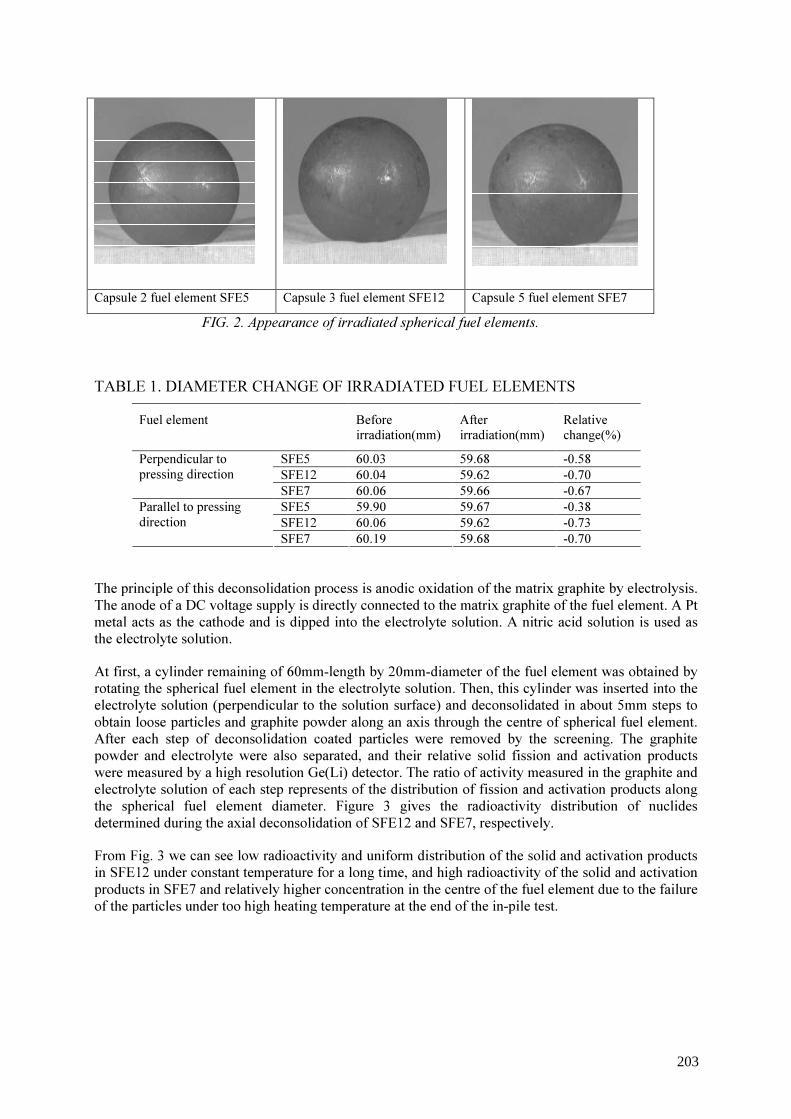
Capsule 2 fuel element SFE5 Capsule 3 fuel element SFE12 Capsule 5 fuel element SFE7
FIG. 2. Appearance of irradiated spherical fuel elements. TABLE 1. DIAMETER CHANGE OF IRRADIATED FUEL ELEMENTS
Fuel element Before irradiation(mm)
After irradiation(mm)
Relative change(%)
SFE5 60.03 59.68 -0.58 SFE12 60.04 59.62 -0.70
Perpendicular to pressing direction
SFE7 60.06 59.66 -0.67 SFE5 59.90 59.67 -0.38 SFE12 60.06 59.62 -0.73
Parallel to pressing direction
SFE7 60.19 59.68 -0.70 The principle of this deconsolidation process is anodic oxidation of the matrix graphite by electrolysis. The anode of a DC voltage supply is directly connected to the matrix graphite of the fuel element. A Pt metal acts as the cathode and is dipped into the electrolyte solution. A nitric acid solution is used as the electrolyte solution. At first, a cylinder remaining of 60mm-length by 20mm-diameter of the fuel element was obtained by rotating the spherical fuel element in the electrolyte solution. Then, this cylinder was inserted into the electrolyte solution (perpendicular to the solution surface) and deconsolidated in about 5mm steps to obtain loose particles and graphite powder along an axis through the centre of spherical fuel element. After each step of deconsolidation coated particles were removed by the screening. The graphite powder and electrolyte were also separated, and their relative solid fission and activation products were measured by a high resolution Ge(Li) detector. The ratio of activity measured in the graphite and electrolyte solution of each step represents of the distribution of fission and activation products along the spherical fuel element diameter. Figure 3 gives the radioactivity distribution of nuclides determined during the axial deconsolidation of SFE12 and SFE7, respectively. From Fig. 3 we can see low radioactivity and uniform distribution of the solid and activation products in SFE12 under constant temperature for a long time, and high radioactivity of the solid and activation products in SFE7 and relatively higher concentration in the centre of the fuel element due to the failure of the particles under too high heating temperature at the end of the in-pile test.
203

FIG. 3. Radial distribution of 60Co, 95Zr, 106Ru, 144Ce, 137Cs and 134Cs determined during axial deconsolidation of SFE 12 and SFE 7. 2.3. Measurement of failure particles 2.3.1. Irradiated microsphere gamma analyzer (IMGA) system The IMGA system records the gamma-ray energy spectra of individual irradiated fuel particle from a large population and performs quantitative analysis on those spectra. Judgement between intact particle and failed particle is based on the activity ratio of two isotopes of caesium (134Cs and 137Cs) and 144Ce. Therefore, IMGA provides the capability of making statically accurate failure fraction measurement on irradiated HTR coated fuel particles. IMGA system utilized in the examination of irradiated HTR-10 fuel particles, which is similar to the IMGA equipment in ORNL [3] in structure of the system, consists of three major components: an automated singularizing particle handling system, a high-resolution gamma detector, and a computer-based pulse height analyzer.
204

As mentioned above, the actual failure fraction is based on a ratio of the activity of a volatile fission product to a non-volatile fission product. The boiling point of Cs element is 678 °C, but 3470 °C for Ce element. Thus in the high temperature irradiation test of HTR fuel, the caesium will escape much more readily from a defective coating than cerium. Thus, a measurement of the activity ratio of 137Cs or 134Cs to 144Ce can inspect the failed particles. 2.3.2. Measurement result of failed particles Each fuel ball contains about 8300 coated fuel particles. 2014 and 1670 particles sampled at random from SFE12 and SFE7, respectively, were inspected by IMGA. Their inspection results are showed in Fig.4 and 5, respectively.
FIG. 4. Activity ratios of 137Cs and 134Cs/144Ce determined on particles of SFE12.
205
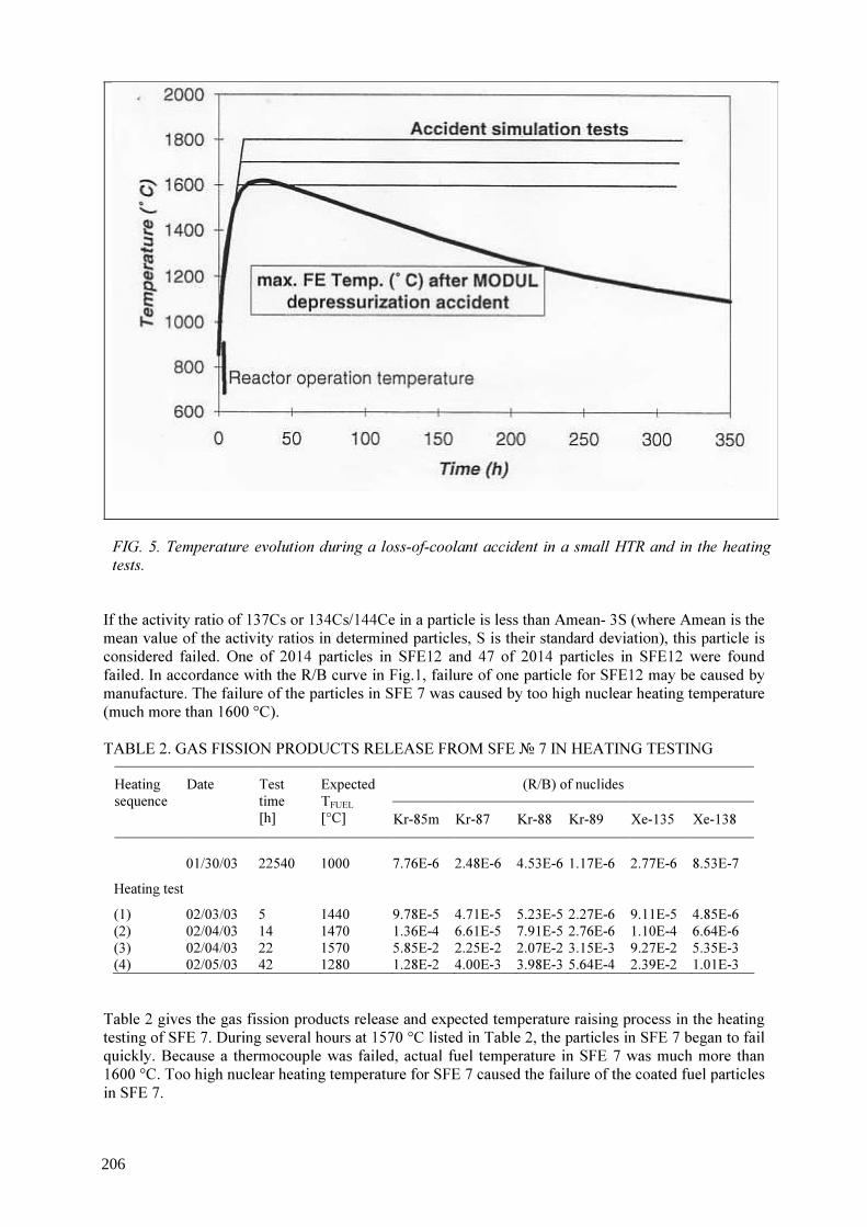
FIG. 5. Temperature evolution during a loss-of-coolant accident in a small HTR and in the heating tests.
If the activity ratio of 137Cs or 134Cs/144Ce in a particle is less than Amean- 3S (where Amean is the mean value of the activity ratios in determined particles, S is their standard deviation), this particle is considered failed. One of 2014 particles in SFE12 and 47 of 2014 particles in SFE12 were found failed. In accordance with the R/B curve in Fig.1, failure of one particle for SFE12 may be caused by manufacture. The failure of the particles in SFE 7 was caused by too high nuclear heating temperature (much more than 1600 °C). TABLE 2. GAS FISSION PRODUCTS RELEASE FROM SFE № 7 IN HEATING TESTING
(R/B) of nuclides Heating sequence
Date Test time [h]
Expected TFUEL [°C] Kr-85m Kr-87 Kr-88 Kr-89 Xe-135 Xe-138
01/30/03 22540 1000 7.76E-6 2.48E-6 4.53E-6 1.17E-6 2.77E-6 8.53E-7 Heating test
(1) 02/03/03 5 1440 9.78E-5 4.71E-5 5.23E-5 2.27E-6 9.11E-5 4.85E-6 (2) 02/04/03 14 1470 1.36E-4 6.61E-5 7.91E-5 2.76E-6 1.10E-4 6.64E-6 (3) 02/04/03 22 1570 5.85E-2 2.25E-2 2.07E-2 3.15E-3 9.27E-2 5.35E-3 (4) 02/05/03 42 1280 1.28E-2 4.00E-3 3.98E-3 5.64E-4 2.39E-2 1.01E-3 Table 2 gives the gas fission products release and expected temperature raising process in the heating testing of SFE 7. During several hours at 1570 °C listed in Table 2, the particles in SFE 7 began to fail quickly. Because a thermocouple was failed, actual fuel temperature in SFE 7 was much more than 1600 °C. Too high nuclear heating temperature for SFE 7 caused the failure of the coated fuel particles in SFE 7.
206
3. Summary The post-irradiation examination is underway now. The following conclusions can be drawn from the already finished some examinations. • One failed coated fuel particles was found by IMGA method in the 2014 particles sampled at
random from the irradiated SFE 12 in capsule 3. The failure of this particle may be caused by manufacture.
• There are about 3% coated fuel particles were failed in the SFE 7 in capsule 5 based on the measurement results of 1670 particles by IMGA. The main failure reason is too high fuel temperature (much more than 1600 °C).
REFERENCES [1] TANG, C.H., TANG, Y.P., et al., Research and Development of Fuel Element for Chinese
10MW High Temperature Gas-cooled Reactor, J. of Nucl. Sci. and Technol., 37, (2000) 9. [2] TANG, C.H., TANG, Y.P., et al., Design and Manufacture of the Fuel Element for the 10
MW High Temperature Gas-cooled Reactor, Nuclear Engineering and Design, 218 (2002), 91-102.
[3] KANIA, M.J., VALENTINE, K.H., The Irradiated Microsphere Gamma Analyzer (IMGA) – an Integrated System for HTGR Coated Particle Fuel Performance Assessment, ORNL-5606, February 1980.
207
Research and development program of HTGR fuel in Japan
K. Sawa, S. Ueta, T. Iyoku Nuclear Science and Engineering Department Japan Atomic Energy Agency, Japan
Abstract. In the high temperature gas-cooled reactors (HTGRs), refractory coated fuel particles are employed as fuel to permit high outlet coolant temperature. The high temperature engineering test reactor (HTTR) employs Tri-isotropic (TRISO) coated fuel particles in the prismatic fuel assembly. Research and development on the HTTR fuel has been carried out spread over about 30 years, in fuel fabrication technologies, fuel performance under normal operation, transient and accident conditions, fission product behavior, and so on. Furthermore, for upgrading of HTGR technologies, an extended burnup TRISO-coated fuel particle and an advanced type of coated fuel particle, ZrC-coated fuel particle in order to keep the integrity at higher operating temperatures has been developed. The present paper provides experiences and current status of research and development works for the HTGR fuel in the HTTR Project.
1. Introduction The high temperature gas-cooled reactors (HTGRs), with its inherent safety and high temperature heat supply of about 1000 oC at the exterior of the reactor, can achieve effective utilization of nuclear energy in various fields by stages. For example, HTGRs make it possible to produce hydrogen with its high temperature heat supply. Hydrogen is expected as alternative energy source for oil near future. Therefore, HTGRs are expected to contribute to the reservation of the global environment and to provide a diverse energy supply [1,2]. In Japan, the Japan Atomic Energy Research Institute JAERI (currently called as Japn Atomic Energy Agency JAEA) has carried out the research and development of HTGRs since 1960's [3]. The construction of high temperature engineering test reactor (HTTR) of 30 MW thermal power started 1991. In December 2000, the HTTR reached full power. Then HTTR has started safety demonstration tests to verify inherent safety features of the HTGRs. The HTTR attained 950 oC of the outlet coolant temperature on April 2004. In the HTGRs, two main fuel element concepts are presently in use, the spherical fuel element and the block-type fuel element as shown in Fig. 1. In both concepts, the high temperature heat supply and inherent safety features of the HTGRs are mainly achieved using refractory-coated fuel particles. Current HTGRs employs so-called TRISO-coated fuel particles, where the fuel microsphere (kernel) are coated with the low-density carbon buffer, the inner isotropic high-density carbon (IPyC), the silicon carbide (SiC) and the outer isotropic high-density carbon (OPyC) layers in this order from within. The HTTR applies TRISO-coated fuel particles with UO2 kernel, which with about 6% in average enrichment and 0.6 mm in diameter. They are dispersed in the graphite matrix and sintered to form a fuel compact as shown in Fig. 1. Fuel compacts are contained in a graphite sleeve to form a fuel rod. Fuel rods are inserted into vertical holes bored in the graphite block. Table 1 summarizes major specifications of the first-loading fuel of the HTTR.
208
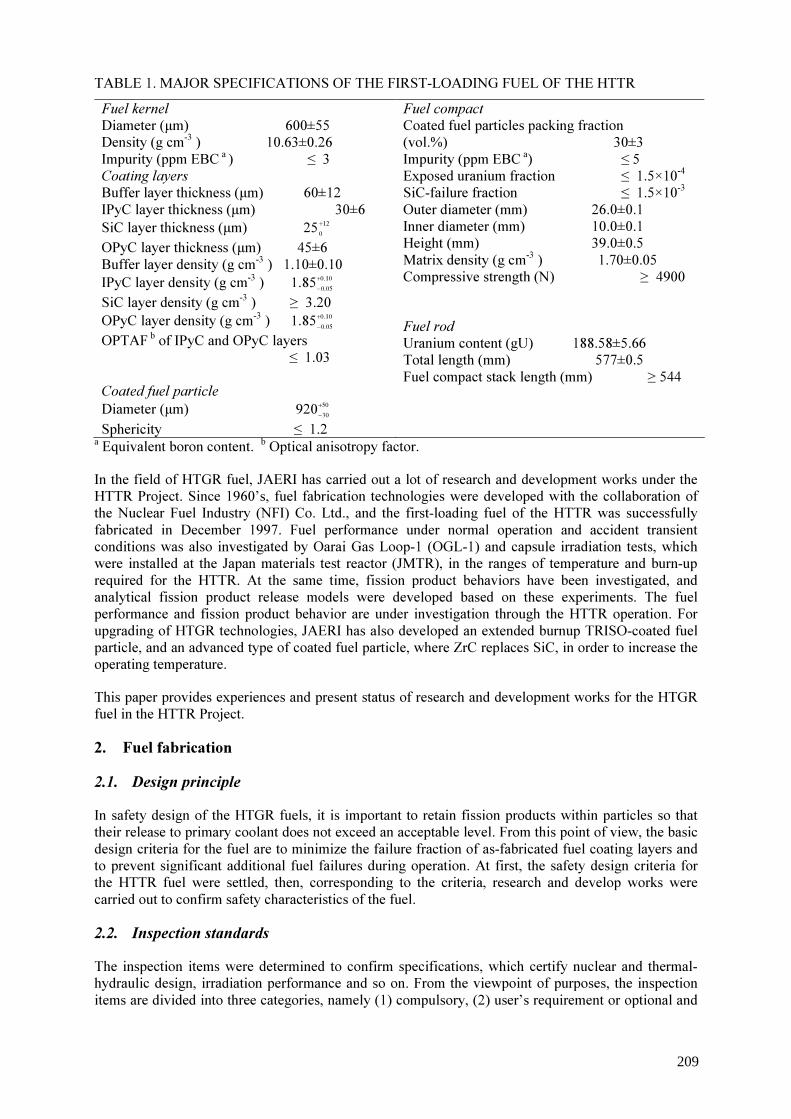
TABLE 1. MAJOR SPECIFICATIONS OF THE FIRST-LOADING FUEL OF THE HTTR Fuel kernel Diameter (µm) 600±55 Density (g cm-3 ) 10.63±0.26 Impurity (ppm EBC a ) ≤ 3 Coating layers Buffer layer thickness (µm) 60±12 IPyC layer thickness (µm) 30±6 SiC layer thickness (µm) 12
025+ OPyC layer thickness (µm) 45±6 Buffer layer density (g cm-3 ) 1.10±0.10 IPyC layer density (g cm-3 ) 10.0
05.085.1 +
−
SiC layer density (g cm-3 ) ≥ 3.20 OPyC layer density (g cm-3 ) 10.0
05.085.1 +
−
OPTAF b of IPyC and OPyC layers ≤ 1.03 Coated fuel particle Diameter (µm) 50
30920+−
Sphericity ≤ 1.2
Fuel compact Coated fuel particles packing fraction (vol.%) 30±3 Impurity (ppm EBC a) ≤ 5 Exposed uranium fraction ≤ 1.5×10⁻⁴ SiC-failure fraction ≤ 1.5×10⁻³ Outer diameter (mm) 26.0±0.1 Inner diameter (mm) 10.0±0.1 Height (mm) 39.0±0.5 Matrix density (g cm-3 ) 1.70±0.05 Compressive strength (N) ≥ 4900 Fuel rod Uranium content (gU) 188.58±5.66 Total length (mm) 577±0.5 Fuel compact stack length (mm) ≥ 544
a Equivalent boron content. b Optical anisotropy factor. In the field of HTGR fuel, JAERI has carried out a lot of research and development works under the HTTR Project. Since 1960’s, fuel fabrication technologies were developed with the collaboration of the Nuclear Fuel Industry (NFI) Co. Ltd., and the first-loading fuel of the HTTR was successfully fabricated in December 1997. Fuel performance under normal operation and accident transient conditions was also investigated by Oarai Gas Loop-1 (OGL-1) and capsule irradiation tests, which were installed at the Japan materials test reactor (JMTR), in the ranges of temperature and burn-up required for the HTTR. At the same time, fission product behaviors have been investigated, and analytical fission product release models were developed based on these experiments. The fuel performance and fission product behavior are under investigation through the HTTR operation. For upgrading of HTGR technologies, JAERI has also developed an extended burnup TRISO-coated fuel particle, and an advanced type of coated fuel particle, where ZrC replaces SiC, in order to increase the operating temperature. This paper provides experiences and present status of research and development works for the HTGR fuel in the HTTR Project. 2. Fuel fabrication 2.1. Design principle In safety design of the HTGR fuels, it is important to retain fission products within particles so that their release to primary coolant does not exceed an acceptable level. From this point of view, the basic design criteria for the fuel are to minimize the failure fraction of as-fabricated fuel coating layers and to prevent significant additional fuel failures during operation. At first, the safety design criteria for the HTTR fuel were settled, then, corresponding to the criteria, research and develop works were carried out to confirm safety characteristics of the fuel. 2.2. Inspection standards The inspection items were determined to confirm specifications, which certify nuclear and thermal-hydraulic design, irradiation performance and so on. From the viewpoint of purposes, the inspection items are divided into three categories, namely (1) compulsory, (2) user’s requirement or optional and
209

(3) vender’s quality control. The sampling rate was also determined by considering the uniformity of inspected data. Three categories are basically classified as (a) small-scattering data, (b) medium-scattering data and (c) large-scattering data. One sample is measured from an inspection lot for the small-scattering data. For the inspection lot with medium-scattering data, three samples are measured and all of them should satisfy criterion. For the large-scattering data, measured data should meet statistically required criterion with 95% confidence. The inspection item, purpose, method and sampling rate in the HTTR fuel fabrication are summarized in reference (4). 2.3. Fabrication technologies Fuel fabrication was undertaken with a laboratory scale capacity (10 kgU/yr) at NFI, and a pilot plant with a capacity of about 40 kgU/yr was subsequently developed in 1972. For irradiation experiments and out-of-pile characterizations, various fuels were produced by this pilot plant. The fabrication capacity was expanded to about 200 kgU/yr in 1983 to produce the fuels for the very high temperature reactor critical assembly (VHTRC). Also, the fuel elements for the OGL-1 experiments carried out after 1984 were produced in this plant. The OGL-1 fuels of last three generations were fabricated using the coater with mass production scale. In 1992, the commercial scale plant with the licensed capacity of 400kgU/yr was launched at NFI, and the fabrication of the first-loading fuel started in June 1995. Around 66 780 fuel compacts, corresponding to 4770 fuel rods, were successfully produced through the fuel kernel, coated fuel particle and fuel compact processes [5]. In December 1997, 150 fuel assemblies were completely formed and stored in new fuel storage cells. From October 2002, the second-loading fuel fabrication has started. Figure 3 depicts a flow diagram of the HTTR fuel production process. The UO2 kernels were fabricated in a gel-precipitation process. After formation of uranyl nitrate solution containing methanol and an additive, spherical droplets are produced by a vibration dropping technique. Following the drying and calcining, reduction of the calcined kernels to UO2 was carried out. Kernel fabrication was completed by a sintering process to produce dense UO2 kernels. The coating layers were deposited on the kernels in a chemical vapor deposition process using a fluidized coater. The TRISO-coating process is divided into four coating processes for the porous PyC, IPyC, SiC and OPyC layers. The buffer and high-density PyC coating layers were derived from C2H2 and C3H6, respectively, and the SiC layer from CH3SiCl3. The amount of charged particles corresponded to 3 kg uranium per coating batch. At a desired temperature, reactants were put into the coater to produce a coating layer on the particles fluidized in the coater. After a certain time to produce the desired thickness of the layer, the reactant gas supply was replaced by argon. The coater and the coated fuel particles were cooled down, and then the coated fuel particles were removed from the bottom of the coater. All UO2 kernels and coated fuel particles are classified by means of a vibrating table to exclude odd shape particles. The as-manufactured quality of the fuel has been improved by the modification of fabrication conditions and processes. The coating failure during coating process was mainly caused by the strong mechanical shocks to the particles given by violent particle fluidization in the coater and by the unloading procedure of the particles. The coating process was improved by optimizing the mode of the particle fluidization and by developing the process without unloading and loading of the particles at the intermediate coating process [6]. The fuel compacts of the HTTR are produced by warm-pressing of the coated fuel particles with graphite powder. In the first step, the coated fuel particles are overcoated by resinated graphite powder with alcohol. The resinated graphite powder is prepared by mixing electro-graphite powder, natural graphite powder, and phenol resin as a binder in the ratio 16:64:20, followed by grinding the mixture to powder. The aim of the overcoating is to avoid direct contact with neighboring particles in the fuel compact. The thickness of overcoating layer is about 200mm, which is determined by the specification for the volume fraction of the coated fuel particles in the fuel compact (30 vol%). Then the overcoated particles are warm-pressed by metal dies to form annular green fuel compacts. The final step of the compaction process is the heat-treatment of the green fuel compacts at 800 oC in flowing N2 to carbonize the binder and at 1800 oC in vacuum to degas the fuel compacts. Then the fabrication process was modified to reduce the defective particle fraction during the compaction process. The compaction process was improved by optimizing the combination of the pressing temperature and the
210

pressing speed of the overcoated particles to avoid the direct contact with neighboring particles in the fuel compact. In the beginning of the first-loading fuel fabrication of the HTTR, which was the first mass-production experience in Japan, unexpected large SiC-failure fractions, about 3-5 particles in a fuel compact, were observed. Then, relations between the measured SiC-failure fractions and fabrication parameters, such as coating layer thickness, overcoating layer thickness, pressing speed, etc., were analyzed during fabrication. Finally, it was concluded that the SiC layer thickness should be thicker than 27 mm to avoid as-fabricated SiC-failure during the compaction process. In addition, there were odd-shaped overcoated particles in which two or three coated fuel particles were included. The odd-shaped overcoated particles failed during compaction process because they could not keep distance to each other. Then, they were removed before compaction process. After these improvements, a significant SiC-failure was no longer observed during fabrication. As shown in Fig. 4, as-fabricated fuel compacts contained almost no through-coatings failed particles and few SiC-defective particles. Average through-coatings and SiC defective fractions were 2×10⁻⁶ and 8×10⁻⁵ respectively [5]. 3. HTTR operation Operating experience from HTGRs comprised all aspects rising from fuel fabrication, irradiation testing, performance modeling to in-reactor chemistry surveillance, fission product release/transport measurement and modeling and reactor component decontamination. As a recent experience, the fuel performance in an accelerated irradiation test of the first-loading fuel and the HTTR operation is introduced below. The irradiation test was carried out confirm the intactness of the first-loading fuel during the HTTR operation [7]. The irradiation was carried out as 94F-9A capsule irradiation test in the JMTR. In order to investigate fuel intactness, the fuel compact was irradiated over 7% FIMA (fission per initial metallic atom) although the maximum burnup in the HTTR design (3.6% FIMA, corresponds to 33 GWd/t). The fuel compacts were irradiated at the temperature of 1300-1350 oC. The maximum burnup and fast neutron fluence for the fuel compacts are 2.7×1025 m-2 and 7 % FIMA, respectively. As results, the measured (R/B) of 88Kr in both inner capsules were less than 10-6, which corresponds to one particle failure in the inner capsule. This result is far smaller than 5.35×10⁻⁴, which is the safety design value. Thus, it was concluded that no significant additional irradiation–induced failure occurred up to 6% FIMA that is about two times higher than 3.6% FIMA of the maximum burnup in the HTTR core. During the rise-to-power test of the HTTR, which started in September 1999, primary coolant sampling measurements were carried out to measure fission gas concentration [8]. The concentrations of fission gas nuclides of 85mKr, 87Kr, 88Kr, 133Xe, 135Xe, 135mXe and 138Xe were less than 0.1 MBq/m3. The fractional releases, (R/B)s, of fission gases were calculated based on the measured concentrations. Figure 5 shows (R/B) of 88Kr as a function of the reactor power. The (R/B) values are as low as 2×10⁻⁹ up to 60% of the reactor power, then increase to 7×10⁻⁹ at full power operation. During the high temperature test operation, where the outlet coolant temperature is 950 oC, the (R/B) became 1.5x10⁻⁸ at full reactor power. The obtained data were analyzed by fission gas release model [9], and the fission gas release mechanism is recoil from the contaminated uranium in the fuel compact matrix in lower reactor power. Beyond 60% of the reactor power, fractional release increases because diffusion release becomes main release mechanism. The increase of (R/B) in the high temperature operation is caused by increase of diffusion release according to fuel temperature elevation. The post-irradiation examinations of the first-loading fuels of the HTTR will be carried out to confirm their irradiation performance and to obtain data on their characteristics in the core. Hot cells were prepared in the HTTR reactor building to handle spent fuel as shown in Fig. 6. In 2007, the first-loading fuel will be reloaded and they will be transferred to the spent fuel storage pool in the reactor building by the fuel-handling machine. An irradiated fuel assembly is disassembled to the fuel rods and a graphite block in the HTTR cell. Then the fuel rods are transferred to the hot laboratory of the
211

Japan materials testing reactor (JMTR). In the JMTR hot laboratory, burnup, failure fractions, etc. are inspected as shown in Fig. 7. 4. Extended burnup fuel In order to investigate fuel behavior at extended burnup, irradiation tests were performed. The irradiation was carried out as HRB-22 and 91F-1A capsule irradiation tests. The fuel for the irradiation tests were called extended burnup fuel, whose target burnup and fast neutron fluence were higher than those of the first-loading fuel of the HTTR. In order to keep fuel integrity up to over 5% FIMA, thickness of buffer and SiC layers of fuel particle were increased. The specifications of the extended burnup fuel are shown in Table 2 compared with the first-loading fuel of the HTTR. The target burnup of the extended burnup fuel is two or three times of the first-loading fuel. In order to mitigate the internal pressure, the extended burnup fuel has been designed to be a thicker buffer layer than that of the first-loading fuel. The fuel compacts were irradiated in the HRB-22 and the 91F-1A capsules at the high flux isotope reactor (HFIR) of Oak Ridge National Laboratory (OENL), and at the JMTR, respectively [11]. The maximum burnup in HBR-22 and 91F-1A capsule irradiation test were attained at 7%FIMA and over 9% FIMA, respectively. TABLE 2. MAJOR SPECIFICATIONS AND IRRADIATION TARGET OF EXTENDED BURNUP FUEL
Extended Burnup Fuel First-loading fuel Kernel diameter (mm) 500 to 550 600 Buffer layer thickness (mm) 90 60 SiC layer thickness (mm) 35 25 to 30 Target burnup (%FIMA) 5 to 10 3.6 Fast neutron fluence (1025m -2) 3 to 5 1.5
In the HRB-22 capsule irradiation test, four additional fuel particle failures were observed during irradiation. In the 91F-1A capsule irradiation test, it was estimated that one additional fuel particle failure occurred based on comparison of measured and calculated R/Bs of 88Kr. The measured fractional releases are shown in Fig. 8. Kernel migration and SiC corrosion was not observed in post-irradiation examinations. One failed particle was found among the deconsolidated coated fuel particles irradiated in the 91F-1A capsule as shown in Fig. 9. It revealed that the OPyC layer was cracked by tensile stress. Calculation result by the pressure vessel failure model(12) showed that no tensile stresses acted on the SiC layers even at the end of irradiation and no pressure vessel failure occurred in the intact particles even in a particle with thin buffer layer with failed OPyC layer. Based on these results, the presumed failure mechanisms are (1) additional through-coatings failure of as-fabricated SiC-failed particles and (2) an excessive increase of internal pressure by the accelerated irradiation. 5. ZrC-TRISO coated fuel particle Zirconium carbide (ZrC) is one of the transition metal carbides, which are characterized by (1) the good-compatibility with structural metals, (2) the high melting point and the thermodynamic stability, (3) the wear resistance etc [13]. Coated fuel particles with chemical vapor deposition-ZrC coatings have been developed at JAERI since early 1970s. Studies include (1) the fabrication processes and characterization techniques developments, (2) the out-of-pile and in-pile performance tests and (3) the post irradiation heating tests simulating accident conditions. Initially, coated UO2 particles with the zirconium carballoy (ZrC+C alloy) coatings without an outer protective PyC Layer were tested. The results on the zirconium-carballoy coated fuel particle are summarized in a report [14]. Although they proved to be less retentive of metal fission products, they showed excellent resistance to chemical attacks by fission
212
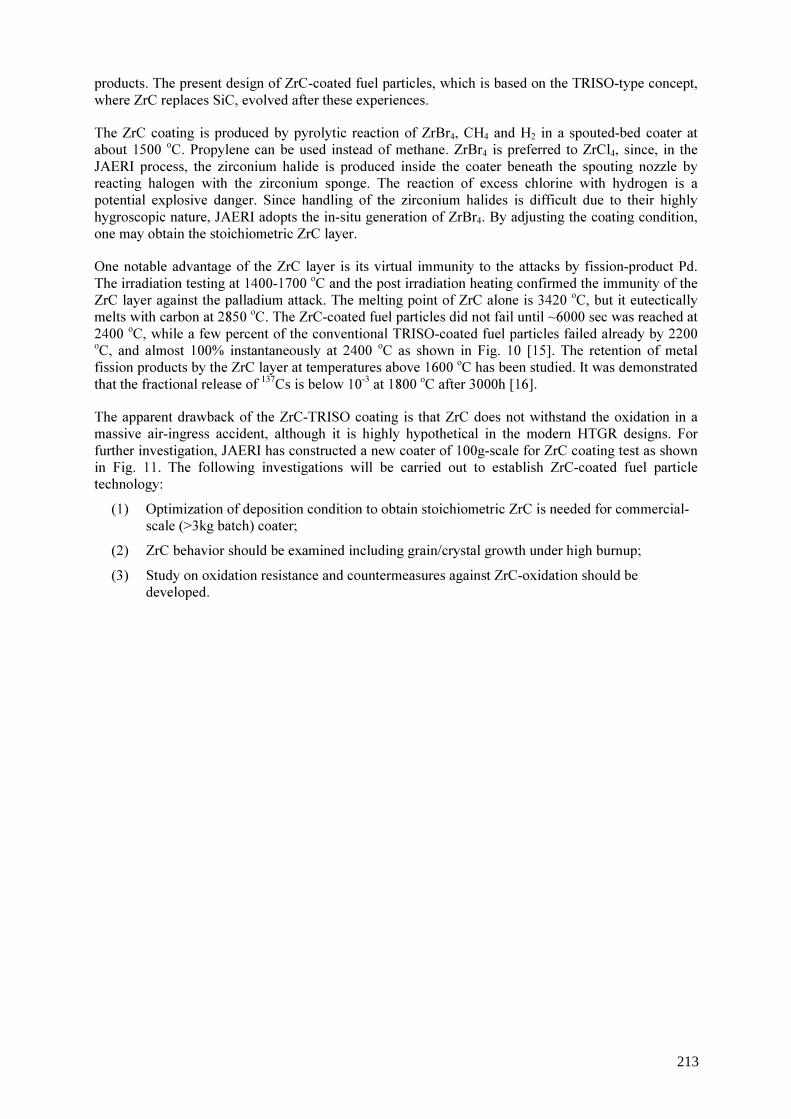
products. The present design of ZrC-coated fuel particles, which is based on the TRISO-type concept, where ZrC replaces SiC, evolved after these experiences. The ZrC coating is produced by pyrolytic reaction of ZrBr4, CH4 and H2 in a spouted-bed coater at about 1500 oC. Propylene can be used instead of methane. ZrBr4 is preferred to ZrCl4, since, in the JAERI process, the zirconium halide is produced inside the coater beneath the spouting nozzle by reacting halogen with the zirconium sponge. The reaction of excess chlorine with hydrogen is a potential explosive danger. Since handling of the zirconium halides is difficult due to their highly hygroscopic nature, JAERI adopts the in-situ generation of ZrBr4. By adjusting the coating condition, one may obtain the stoichiometric ZrC layer. One notable advantage of the ZrC layer is its virtual immunity to the attacks by fission-product Pd. The irradiation testing at 1400-1700 oC and the post irradiation heating confirmed the immunity of the ZrC layer against the palladium attack. The melting point of ZrC alone is 3420 oC, but it eutectically melts with carbon at 2850 oC. The ZrC-coated fuel particles did not fail until ~6000 sec was reached at 2400 oC, while a few percent of the conventional TRISO-coated fuel particles failed already by 2200 oC, and almost 100% instantaneously at 2400 oC as shown in Fig. 10 [15]. The retention of metal fission products by the ZrC layer at temperatures above 1600 oC has been studied. It was demonstrated that the fractional release of 137Cs is below 10-3 at 1800 oC after 3000h [16]. The apparent drawback of the ZrC-TRISO coating is that ZrC does not withstand the oxidation in a massive air-ingress accident, although it is highly hypothetical in the modern HTGR designs. For further investigation, JAERI has constructed a new coater of 100g-scale for ZrC coating test as shown in Fig. 11. The following investigations will be carried out to establish ZrC-coated fuel particle technology: (1) Optimization of deposition condition to obtain stoichiometric ZrC is needed for commercial-
scale (>3kg batch) coater; (2) ZrC behavior should be examined including grain/crystal growth under high burnup; (3) Study on oxidation resistance and countermeasures against ZrC-oxidation should be
developed.
213
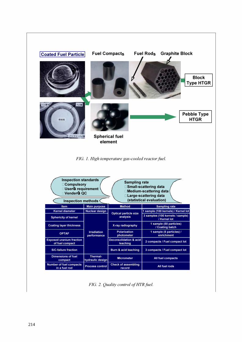
FIG. 1. High temperature gas-cooled reactor fuel.
FIG. 2. Quality control of HTR fuel.
Spherical fuelelement
BlockType HTGR
Fuel Compacts Graphite BlockFuel RodsCoated Fuel Particle
Pebble TypeHTGR
Number of fuel compactsin a fuel rod
Sampling rate
All fuel rodsCheck of assemblingrecordProcess control
All fuel compactsMicrometerThermal-hydraulic design
Dimensions of fuelcompact
MethodMain purposeItem
3 compacts / Fuel compact lotBurn & acid leachingSiC-failure fraction
2 compacts / Fuel compact lotDeconsolidation & acidleaching
Exposed uranium fractionof fuel compact
1 sample (5 particles) /enrichment
PolarizationphotometerOPTAF
1 sample (50 particles)/ Coating batchX-ray radiographyCoating layer thickness
3 samples (100 kernels / sample)/ Kernel lot
Irradiationperformance
Sphericity of kernel1 sample (100 kernels) / Kernel lotOptical particle size
analysisNuclear designKernel diameter
Sampling rate�Small-scattering data�Medium-scattering data�Large-scattering data (statistical evaluation)Inspection methods
Inspection standards�Compulsory�UserÕs requirement�VenderÕs QC
214

FIG. 4. Number of failed particles in a fuel compact in the first loading fuel fabrication:-average through coating failure, 2x10⁻⁶ (spec. 1.5x10⁻⁴)-average SiC failure fraction, 8x10⁻⁵ (spec. 1.5x10⁻³).
Fig.3 Flow Diagram of HTTR Fuel Fabrication
0%
20%
40%
60%
80%
100%
Freq
uenc
y
0 1 2 3 4 5 6 7 8 9 10
SiC-failure
Through-coatings failure
FIG. 3. Flow diagram of HTTR fuel fabrication
215

FIG. 5. 88Kr release rates during rise-to-power operation: -Fission gases released from through-coatings failed particle and contaminated uranium in fuel compact by diffusion and recoil. -In the HTTR, fission gas release mechanism changes from recoil to diffusion from contaminated uranium.
FIG. 6. Hot cells in the HTTR reactor building.
Fig. 6 Hot cells in the HTTR reactor building
0.0E+00
5.0E-09
1.0E-08
1.5E-08
0 20 40 60 80 100Reactor power (%)
Frac
tiona
l rel
ease
of
88Kr
0
-8
-9
-8
Prediction for hightemperature operation
Prediction for rated
216
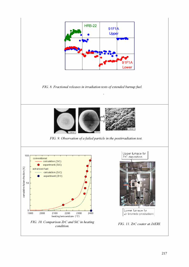
Fig. 10 Compari son ZrC and SiC in heating condit ion.
Fig. 9 Observation of a failed particle in the postirradiation test.
Fig. 11 ZrC coater at JAERI.
HRB-22 91F1AUpper
91F1ALower
Fig.8 Fractional releases in irradiation tests of extended burnup fuel
FIG. 8 FIG. 8. Fractional releases in irradiation tests of extended burnup fuel.
FIG. 9. Observation of a failed particle in the postirradiation test.
FIG. 10. Comparison ZrC and SiC in heating condition. FIG. 11. ZrC coater at JAERI.
217
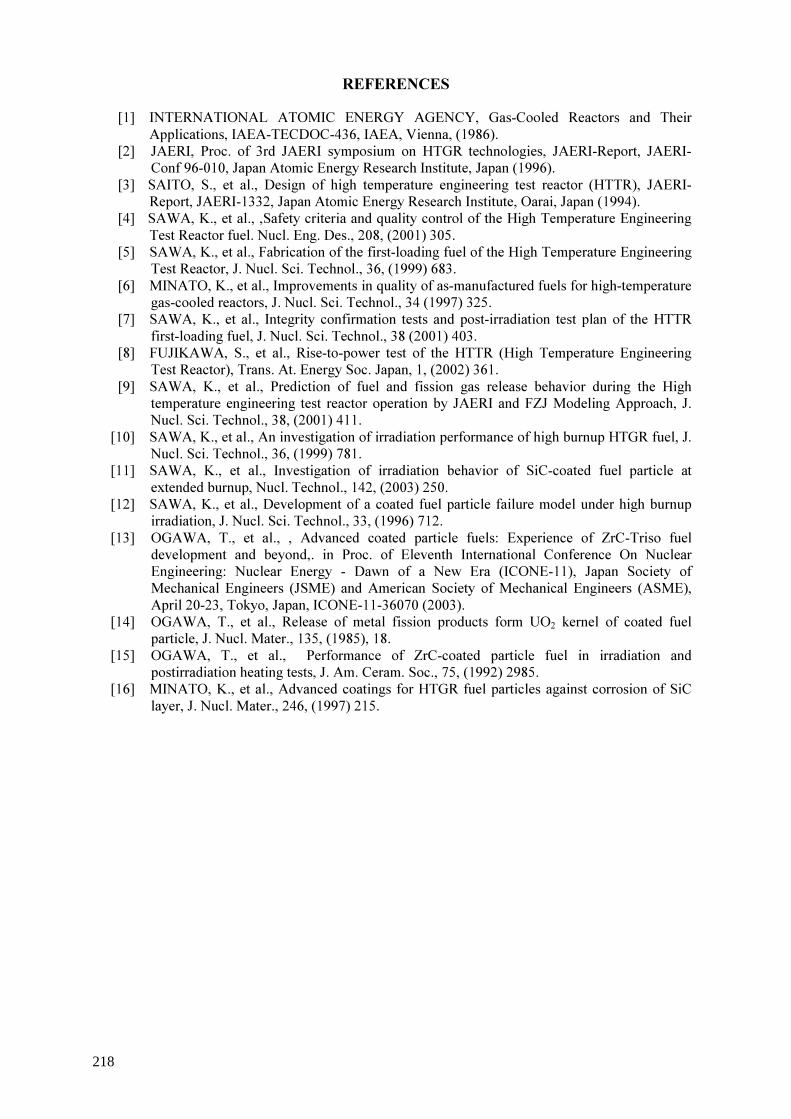
REFERENCES
[1] INTERNATIONAL ATOMIC ENERGY AGENCY, Gas-Cooled Reactors and Their Applications, IAEA-TECDOC-436, IAEA, Vienna, (1986).
[2] JAERI, Proc. of 3rd JAERI symposium on HTGR technologies, JAERI-Report, JAERI-Conf 96-010, Japan Atomic Energy Research Institute, Japan (1996).
[3] SAITO, S., et al., Design of high temperature engineering test reactor (HTTR), JAERI-Report, JAERI-1332, Japan Atomic Energy Research Institute, Oarai, Japan (1994).
[4] SAWA, K., et al., ,Safety criteria and quality control of the High Temperature Engineering Test Reactor fuel. Nucl. Eng. Des., 208, (2001) 305.
[5] SAWA, K., et al., Fabrication of the first-loading fuel of the High Temperature Engineering Test Reactor, J. Nucl. Sci. Technol., 36, (1999) 683.
[6] MINATO, K., et al., Improvements in quality of as-manufactured fuels for high-temperature gas-cooled reactors, J. Nucl. Sci. Technol., 34 (1997) 325.
[7] SAWA, K., et al., Integrity confirmation tests and post-irradiation test plan of the HTTR first-loading fuel, J. Nucl. Sci. Technol., 38 (2001) 403.
[8] FUJIKAWA, S., et al., Rise-to-power test of the HTTR (High Temperature Engineering Test Reactor), Trans. At. Energy Soc. Japan, 1, (2002) 361.
[9] SAWA, K., et al., Prediction of fuel and fission gas release behavior during the High temperature engineering test reactor operation by JAERI and FZJ Modeling Approach, J. Nucl. Sci. Technol., 38, (2001) 411.
[10] SAWA, K., et al., An investigation of irradiation performance of high burnup HTGR fuel, J. Nucl. Sci. Technol., 36, (1999) 781.
[11] SAWA, K., et al., Investigation of irradiation behavior of SiC-coated fuel particle at extended burnup, Nucl. Technol., 142, (2003) 250.
[12] SAWA, K., et al., Development of a coated fuel particle failure model under high burnup irradiation, J. Nucl. Sci. Technol., 33, (1996) 712.
[13] OGAWA, T., et al., , Advanced coated particle fuels: Experience of ZrC-Triso fuel development and beyond,. in Proc. of Eleventh International Conference On Nuclear Engineering: Nuclear Energy - Dawn of a New Era (ICONE-11), Japan Society of Mechanical Engineers (JSME) and American Society of Mechanical Engineers (ASME), April 20-23, Tokyo, Japan, ICONE-11-36070 (2003).
[14] OGAWA, T., et al., Release of metal fission products form UO2 kernel of coated fuel particle, J. Nucl. Mater., 135, (1985), 18.
[15] OGAWA, T., et al., Performance of ZrC-coated particle fuel in irradiation and postirradiation heating tests, J. Am. Ceram. Soc., 75, (1992) 2985.
[16] MINATO, K., et al., Advanced coatings for HTGR fuel particles against corrosion of SiC layer, J. Nucl. Mater., 246, (1997) 215.
218

Session 4
NOVEL IDEAS AND APPLICATION RELATED TO COATED PARTICLE FUEL
Y. Tsuchie Japan
S.D. Rubin
United States of America

A deep burn fuel management strategy for the transmutation of light water reactors waste in the gas turbine–modular helium reactor
A. Talamo, W. Gudowski Royal Institute of Technology (KTH) Stockholm, Sweden
Abstract. We have investigated the waste actinide burnup capabilities of the gas turbine modular helium reactor (GT-MHR), similar to the reactor being designed by General Atomics and Minatom for surplus weapons plutonium destruction) with the Monte Carlo continuous energy burnup code (MCB), an extension of Monte Carlo N-particle transport code (MCNP) developed at the Royal Institute of Technology in Stockholm and the University of Science and Technology in Cracow. The GT-MHR is a gas-cooled, graphite-moderated reactor, which can be powered with a wide variety of fuels, like thorium, uranium or plutonium. In the present studies, the GT-MHR is fueled with the transuranic actinides contained in light water reactors (LWRs) spent fuel for the purpose of destroying them as completely as possible. The driver fuel (DF) of the GT-MHR uses fissile isotopes (e.g. 239Pu and 241Pu), previously generated in the LWRs, and maintains criticality conditions in the GT-MHR. After an irradiation of three years, the spent driver fuel is reprocessed and its remaining actinides are manufactured into fresh transmutation fuel (TF). Transmutation Fuel mainly contains non-fissile actinides that undergo neutron capture and transmutation during the subsequent three-year irradiation in the GT-MHR. At the same time, TF provides control and negative reactivity feedback to the reactor. The destruction of more than 94% of 239Pu and the other geologically problematic actinide species makes this reactor a valid proposal for the reduction of nuclear waste and the prevention of proliferation.
1. Introduction
One of the major problems for the civilian use of the nuclear energy consists in the final disposal of the waste that comes mostly from light water reactors (LWRs). In the present studies we propose an alternative solution in which LWRs waste is transmuted by the gas turbine modular helium reactor (GT-MHR). In this scenario the LWRs waste is reprocessed by uranium and fission products extraction (UREX) and manufactured into new fresh fuel for the GT-MHR. The final products of the LWRs spent fuel reprocessing are NpPuO1.7 and AmCmO1.7; the first material constitutes the driver fuel (DF). The DF is the primary nuclear fuel for the GT-MHR and it sustains the fission chain reaction, mainly by 239Pu. Spent DF is mixed after discharge from the reactor core with the AmCmO1.7, which was set-aside after UREX process, to build fresh transmutation fuel (TF). After irradiation, spent TF is sent into the repository. Pu-239 plays a key role in the operation of the GT-MHR, because it is the most abundant fissile isotope in LWR spent fuel after UREX, and therefore it provides most of the reactivity of the DF. Pu-239 exhibits a particularly undesirable neutronic behavior in the neutron energy range of 0.25-1 eV, where resonances of fission and capture cross sections of 239Pu set a positive temperature reactivity feedback, since the capture to fission cross section ratio, so called alpha parameter, decreases with the increase of temperature. Usually, the undesired behavior of 239Pu in the neutron energy range above 0.25 eV is mitigated by adding 167Er as burnable poison. Nevertheless, in graphite moderated reactors, 167Er might be replaced by 241Am, 237Np and 240Pu, which are abundant in the TF. These actinide isotopes have resonances in the right energy range to compensate for the increased reactivity of 239Pu; they need to be transmuted and are also fertile. Therefore in the GT-MHR, they can replace the parasitic rare earth burnable poisons to great advantage.
221

2. The deep burn fuel management strategy In the GT-MHR, the hexagonal fuel blocks are disposed along three rings; Fig. 1 describes in detail the reactor.
FIG. 1. The gas turbine modular high temperature reactor GT-MHR.
The shuffling strategy moves hexagonal fuel blocks only radially. While the fresh driver fuel is fixed in composition, the fresh transmutation fuel is in part made of irradiated (spent) DF; therefore, the TF composition changes with time and it reaches the equilibrium according to the specific reactor refuelling strategy. From a starting point with only DF, in order to arrive at equilibrium conditions with representative mass flows for both driver and transmutation fuels, we adopted a 12-year “fuel strategy” consisting of periodic refuelling and shuffling. At the end of the 12th year the reactor is at
34
21
CORE
legend:1: Graphite2: Fuel outer ring.3: Fuel central ring.4: Fuel inner ring.
2 431
FUEL BLOCK
legend:1: Graphite matrix.2: Driver Fuel pin.3: Coolant channel.4: Transmuter Fuel pin.
TRISO PARTICLE
legend:1: Fuel Oxide.2: Porous carbon.3: Pyrocarbon.4: Silicon Carbide.5: Pyrocarbon.
FUEL PIN
8 m36
cm1.2
44 cm
300 µ
m (D
F) -2
00 µm
(TF)
1 42 3 5
222
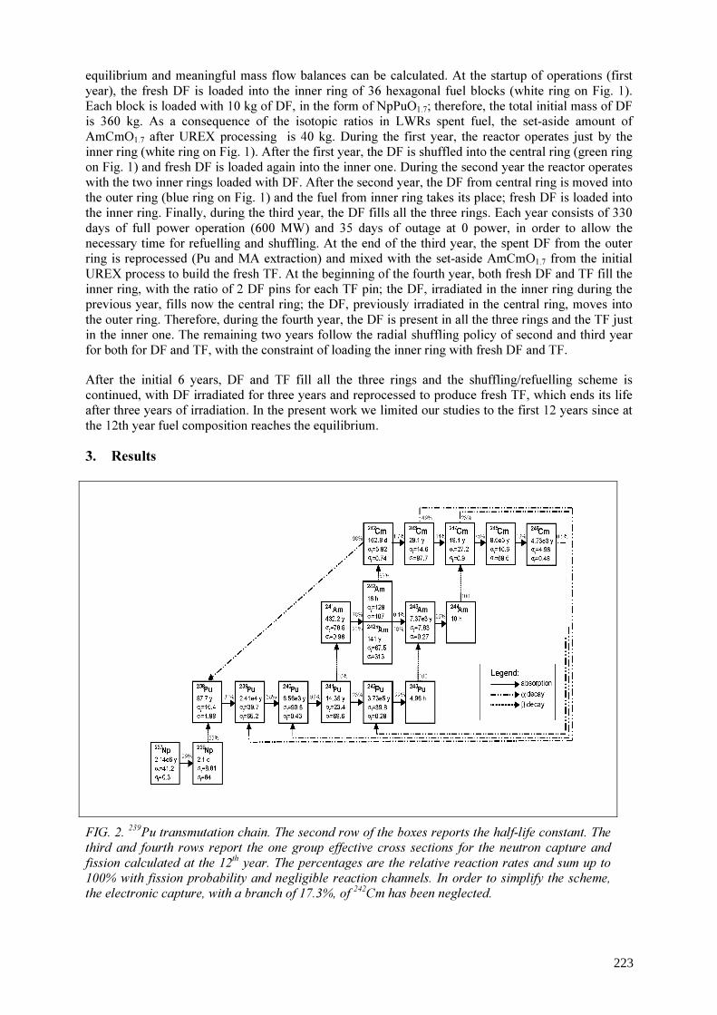
equilibrium and meaningful mass flow balances can be calculated. At the startup of operations (first year), the fresh DF is loaded into the inner ring of 36 hexagonal fuel blocks (white ring on Fig. 1). Each block is loaded with 10 kg of DF, in the form of NpPuO1.7; therefore, the total initial mass of DF is 360 kg. As a consequence of the isotopic ratios in LWRs spent fuel, the set-aside amount of AmCmO1.7 after UREX processing is 40 kg. During the first year, the reactor operates just by the inner ring (white ring on Fig. 1). After the first year, the DF is shuffled into the central ring (green ring on Fig. 1) and fresh DF is loaded again into the inner one. During the second year the reactor operates with the two inner rings loaded with DF. After the second year, the DF from central ring is moved into the outer ring (blue ring on Fig. 1) and the fuel from inner ring takes its place; fresh DF is loaded into the inner ring. Finally, during the third year, the DF fills all the three rings. Each year consists of 330 days of full power operation (600 MW) and 35 days of outage at 0 power, in order to allow the necessary time for refuelling and shuffling. At the end of the third year, the spent DF from the outer ring is reprocessed (Pu and MA extraction) and mixed with the set-aside AmCmO1.7 from the initial UREX process to build the fresh TF. At the beginning of the fourth year, both fresh DF and TF fill the inner ring, with the ratio of 2 DF pins for each TF pin; the DF, irradiated in the inner ring during the previous year, fills now the central ring; the DF, previously irradiated in the central ring, moves into the outer ring. Therefore, during the fourth year, the DF is present in all the three rings and the TF just in the inner one. The remaining two years follow the radial shuffling policy of second and third year for both for DF and TF, with the constraint of loading the inner ring with fresh DF and TF. After the initial 6 years, DF and TF fill all the three rings and the shuffling/refuelling scheme is continued, with DF irradiated for three years and reprocessed to produce fresh TF, which ends its life after three years of irradiation. In the present work we limited our studies to the first 12 years since at the 12th year fuel composition reaches the equilibrium. 3. Results
FIG. 2. 239Pu transmutation chain. The second row of the boxes reports the half-life constant. The third and fourth rows report the one group effective cross sections for the neutron capture and fission calculated at the 12th year. The percentages are the relative reaction rates and sum up to 100% with fission probability and negligible reaction channels. In order to simplify the scheme, the electronic capture, with a branch of 17.3%, of 242Cm has been neglected.
223
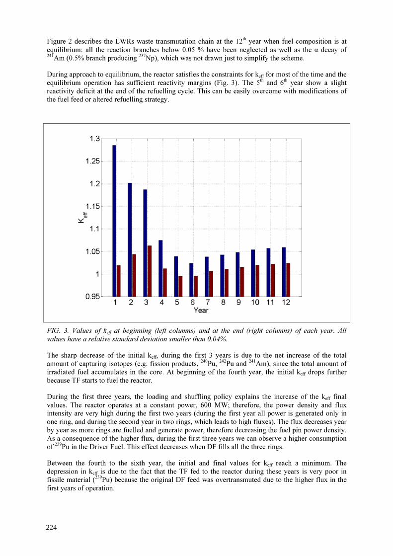
Figure 2 describes the LWRs waste transmutation chain at the 12th year when fuel composition is at equilibrium: all the reaction branches below 0.05 % have been neglected as well as the α decay of 241Am (0.5% branch producing 237Np), which was not drawn just to simplify the scheme. During approach to equilibrium, the reactor satisfies the constraints for keff for most of the time and the equilibrium operation has sufficient reactivity margins (Fig. 3). The 5th and 6th year show a slight reactivity deficit at the end of the refuelling cycle. This can be easily overcome with modifications of the fuel feed or altered refuelling strategy.
The sharp decrease of the initial keff, during the first 3 years is due to the net increase of the total amount of capturing isotopes (e.g. fission products, 240Pu, 242Pu and 241Am), since the total amount of irradiated fuel accumulates in the core. At beginning of the fourth year, the initial keff drops further because TF starts to fuel the reactor. During the first three years, the loading and shuffling policy explains the increase of the keff final values. The reactor operates at a constant power, 600 MW; therefore, the power density and flux intensity are very high during the first two years (during the first year all power is generated only in one ring, and during the second year in two rings, which leads to high fluxes). The flux decreases year by year as more rings are fuelled and generate power, therefore decreasing the fuel pin power density. As a consequence of the higher flux, during the first three years we can observe a higher consumption of 239Pu in the Driver Fuel. This effect decreases when DF fills all the three rings. Between the fourth to the sixth year, the initial and final values for keff reach a minimum. The depression in keff is due to the fact that the TF fed to the reactor during these years is very poor in fissile material (239Pu) because the original DF feed was overtransmuted due to the higher flux in the first years of operation.
FIG. 3. Values of keff at beginning (left columns) and at the end (right columns) of each year. All values have a relative standard deviation smaller than 0.04%.
224
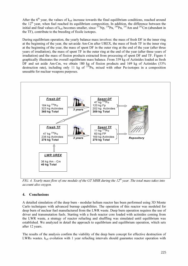
After the 6th year, the values of keff increase towards the final equilibrium conditions, reached around the 12th year, when fuel reached its equilibrium composition. In addition, the difference between the initial and final values of keff becomes smaller, since 237Np, 238Pu, 240Pu, 241Am and 242Cm (abundant in the TF), contribute to the breeding of fissile isotopes. During equilibrium operation, the yearly balance mass involves: the mass of fresh DF in the inner ring at the beginning of the year, the set-aside Am-Cm after UREX, the mass of fresh TF in the inner ring at the beginning of the year, the mass of spent DF in the outer ring at the end of the year (after three years of irradiation), the mass of spent TF in the outer ring at the end of the year (after three years of irradiation) and the mass of fission products extracted from processing of spent DF and TF. Figure 4 graphically illustrates the overall equilibrium mass balance. From 359 kg of Actinides loaded as fresh DF and set aside Am-Cm, we obtain 180 kg of fission products and 169 kg of Actinides (53% destruction rate), including only 11 kg of 239Pu, mixed with other Pu-isotopes in a composition unusable for nuclear weapons purposes.
FIG. 4. Yearly mass flow of one module of the GT MHR during the 12th year. The total mass takes into account also oxygen.
4. Conclusions A detailed simulation of the deep burn - modular helium reactor has been performed using 3D Monte Carlo techniques with advanced burnup capabilities. The operation of this reactor was modeled for deep burn of nuclear fuel manufactured from the LWR waste. Deep burn operation requires the use of driver and transmutation fuels. Starting with a fresh reactor core loaded with actinides coming from the LWR waste, a strategy of reactor refueling and shuffling was simulated until equilibrium was established. We analyzed in detail the approach to equilibrium and equilibrium operation, which sets after 12 years. The results of the analysis confirm the viability of the deep burn concept for effective destruction of LWRs wastes. keff evolution with 1 year refueling intervals should guarantee reactor operation with
3 years
Spent TF 11 kg 239Pu 60 kg FP 169 kg Actinides 270 kg Total
Spent DF 47 kg 239Pu 120 kg Fp 202 kg Actinides 359 kg Total
Fresh TF 47 kg 239Pu 236 kg Actinides 276 kg Total
Fresh DF 184 kg 239Pu 323 kg Actinides 360 kg Total
LWR UREX 36 kg Am - Cm 40 kg Total
3 years Repository
225

sufficient reactivity margins. Year 5 and 6 indicate a temporary slight shortage of reactivity that can easily be overcome with external means (e.g. slight modification of feed fuel - TF or DF). Equilibrium destruction rates for 239Pu, overall Pu and all Actinides are respectively: 94%, 61% and 53%. The residual waste contains Pu in isotopic composition that does not raise proliferation concerns. Moreover, Am and Np content is significantly reduced by more than 50%. This performance depends on the chosen refueling intervals, and can be significantly improved, if desired. Buildup of 238Pu and 244Cm was observed, which requires further studies to investigate if it is necessary an intermediate storage of the spent TF. These are short-lived isotopes that do not contribute to degradation of repository performance and are effectively immobilized within the TRISO-particle residual waste.
REFERENCES [1] TALAMO, A., GUDOWSKI, W., VENNERI, F., The burnup capabilities of the Deep Burn
Modular Helium Reactor analyzed by the Monte Carlo Continuous Energy Code MCB. Annals of Nuclear Energy 31/2, (2004) pp. 173-196.
[2] TALAMO, A., GUDOWSKI, W., CETNAR, J., VENNERI, F., Key physical parameters and temperature reactivity coefficients of the Deep Burn Modular Helium Reactor fueled with LWR waste. Annals of Nuclear Energy, 31/16 (2004) pp. 1913-1937.
[3] GENERAL ATOMIC, GT-MHR conceptual design description report, U.S. Nuclear Regulatory Commission, GA/NRC-337-02, (2002).
[4] CETNAR, J., GUDOWSKI, W., WALLENIUS, J., TUCEK, K., Simulation of nuclide transmutation with Monte-Carlo Continuous Energy Burnup Code (MCB1C), Proc. Accelerator application 2001 and ADTTA 2001 Nuclear application in the new millennium, (AccAPP-ADTTA'01), November 11-15, 2001, Reno, Nevada,, USA Nov., American Nuclear Society, (2001)
[5] CETNAR, J., GUDOWSKI, W., WALLENIUS, J., MCB: a continuous energy Monte Carlo burnup simulation code, in actinide and fission product partitioning and transmutation. EUR 18898 EN, OECD/NEA 523, (1999).
226
Fuel requirements for the advanced high–temperature reactor: Graphite coated–particle fuel and molten fluoride salt coolant
C.W. Forsberg a, M.A. Feltus b a b Oak Ridge National Laboratory, Oak Ridge, TN, USA U.S. Department of Energy, Washington, D.C., USA
Abstract. The technological base for high-temperature reactors is the graphite-matrix coated-particle fuel that can operate at temperatures approaching 1250 °C with allowable accident temperatures approaching 1600 °C. Historically, the reactor coolant has been helium. However, another reactor coolant is also compatible with graphite-based fuels: molten fluoride salts. Oak Ridge National Laboratory, Sandia National Laboratories, and the University of California at Berkeley are developing a new reactor concept, the advanced high-temperature reactor (AHTR), which uses graphite-matrix coated-particle fuel with a clean high-temperature, low-pressure molten-fluoride-salt reactor coolant. The molten salt has a boiling point near 1400 °C. Recent studies have developed a preconceptual design for 2400-MW(t) AHTR. Two outlet coolant temperatures were evaluated: 800 C and 1000 °C. The low pressure and high-temperature output matches the need for heat to produce hydrogen using thermochemical production techniques or electricity at high efficiency. While the AHTR uses the same coated-particle fuels as those used in helium-cooled reactors, the difference in coolant characteristics and reactor design will likely change some of the fuel requirements. The superior heat transfer characteristics of liquid molten salts compared with those of gaseous helium reduces peak fuel operating temperatures. The decay-heat-cooling system reduces peak accident temperatures by several hundred degrees Celsius. The ability of the molten salt to absorb fission products reduces those fuel quality requirements necessary to minimize off-site radiation exposures under accident conditions. Because more fuel blocks must be moved during a refueling outage, the larger power output of the AHTR implies longer refueling times if the fuel has the same geometry and power densities as modular gas-cooled reactor fuel. Consequently, there are strong economic incentives to increase the power density, increase fuel burnup, and modify the fuel geometry to reduce refueling times. Neutronic requirements may require other modifications as well.
1. Introduction A new type of high-temperature reactor is being developed [1-3]: the advanced high-temperature reactor (AHTR). The goal is to develop a reactor with a combination of three technical characteristics in a single reactor: high temperature, passive safety, and large power output. Only one type of nuclear fuel has been fully demonstrated for use in high-temperature reactors for commercial applications: the graphite-matrix coated-particle fuel. Although helium has historically been the coolant used in high-temperature reactors, graphite-based fuel is also compatible with one other type of coolant: molten fluoride salts. For example, for over a century the aluminum industry has produced aluminum by electrolytic methods in graphite baths filled with molten fluoride salts at ~1000 °C. The AHTR uses a low-pressure molten fluoride salt with a boiling point of ~1400 ºC. The AHTR is different from the traditional molten salt reactor (MSR). In an MSR, the uranium and resultant fission products are dissolved in a molten fluoride salt. In the 1950s and 1960s, the United States began development of MSRs for military aircraft propulsion and then as breeder reactors that produced electricity [4]. Two experimental reactors were built and successfully operated. In the molten salt reactor experiment [an 8-MW(t) reactor], the reactor core was composed of pieces of bare graphite that served as the neutron moderator with the molten fuel salt rapidly flowing by the graphite. In contrast, the AHTR uses a solid fuel and a clean molten salt coolant. The AHTR is thus different from the MSR but builds upon that earlier technology.
227

Because the AHTR uses a liquid coolant, rather than a gas coolant, some differences in requirements for the fuel will exist. This paper describes the reactor concept and the potential differences in fuel requirements. 2. AHTR description The AHTR is a high-temperature reactor (Fig. 1, Table 1) that uses the same general type of fuel used in modular high-temperature gas-cooled reactors (MHTGRs). The optically transparent molten salt coolant is a mixture of fluoride salts with freezing points near 400 °C and atmospheric boiling points of ~1400 °C. The reactor operates near atmospheric pressure. At operating conditions, the molten-salt heat-transfer properties are similar to those of water at room temperature. Heat is transferred from the reactor core by the primary molten salt coolant to an intermediate heat-transfer loop. The intermediate heat-transfer loop uses a secondary molten salt coolant to move the heat to the turbine hall. In the turbine hall, the heat is transferred to a multi-reheat nitrogen or helium Brayton cycle power conversion system for the production of electricity. If hydrogen is to be produced, the intermediate heat-transfer loop transports heat to a thermochemical plant that converts water and high-temperature heat to hydrogen (H2) and oxygen.
FIG. 1. Schematic of the AHTR for electricity production. The AHTR facility layout (Fig. 2) is similar to that for the S-PRISM sodium-cooled fast reactor designed by General Electric. Both reactors operate at low pressure and high temperature; thus, they have similar design constraints. The 9.2-m diameter vessel of the AHTR is the same size as that used by the S-PRISM. Earlier engineering studies indicated that this was the largest practical size of low-pressure reactor vessel. The vessel size determines the power output. For our initial studies, we assumed fuel and power densities (8.3 W/cm3) to be similar to those of MHTGRs.
228
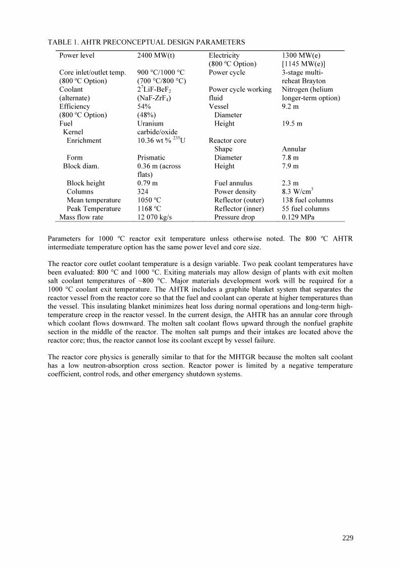
TABLE 1. AHTR PRECONCEPTUAL DESIGN PARAMETERS Power level 2400 MW(t) Electricity
(800 ºC Option) 1300 MW(e) [1145 MW(e)]
Core inlet/outlet temp. (800 ºC Option)
900 °C/1000 °C (700 °C/800 °C)
Power cycle 3-stage multi-reheat Brayton
Coolant (alternate)
27LiF-BeF2 (NaF-ZrF4)
Power cycle working fluid
Nitrogen (helium longer-term option)
Efficiency (800 ºC Option)
54% (48%)
Vessel Diameter
9.2 m Fuel Kernel
Uranium carbide/oxide
Height 19.5 m Enrichment 10.36 wt % 235U Reactor core
Shape Annular
Form Prismatic Diameter 7.8 m Block diam. 0.36 m (across
flats) Height 7.9 m
Block height 0.79 m Fuel annulus 2.3 m Columns 324 Power density 8.3 W/cm3 Mean temperature 1050 ºC Reflector (outer) 138 fuel columns Peak Temperature 1168 ºC Reflector (inner) 55 fuel columns Mass flow rate 12 070 kg/s Pressure drop 0.129 MPa
Parameters for 1000 ºC reactor exit temperature unless otherwise noted. The 800 ºC AHTR intermediate temperature option has the same power level and core size. The reactor core outlet coolant temperature is a design variable. Two peak coolant temperatures have been evaluated: 800 °C and 1000 °C. Exiting materials may allow design of plants with exit molten salt coolant temperatures of ~800 °C. Major materials development work will be required for a 1000 °C coolant exit temperature. The AHTR includes a graphite blanket system that separates the reactor vessel from the reactor core so that the fuel and coolant can operate at higher temperatures than the vessel. This insulating blanket minimizes heat loss during normal operations and long-term high-temperature creep in the reactor vessel. In the current design, the AHTR has an annular core through which coolant flows downward. The molten salt coolant flows upward through the nonfuel graphite section in the middle of the reactor. The molten salt pumps and their intakes are located above the reactor core; thus, the reactor cannot lose its coolant except by vessel failure. The reactor core physics is generally similar to that for the MHTGR because the molten salt coolant has a low neutron-absorption cross section. Reactor power is limited by a negative temperature coefficient, control rods, and other emergency shutdown systems.
229

FIG. 2. Schematic of the AHTR nuclear island and vessel.
When a reactor shuts down, radioactive decay heat continues to be generated in the reactor core at a rate that decreases over time. If this heat is not removed, the reactor will overheat and the core will be damaged, such as occurred during the Three Mile Island accident. The AHTR uses passive reactor vessel auxiliary cooling (RVAC) systems similar to that developed for decay heat removal in the General Electric sodium-cooled S-PRISM reactor. The reactor and decay-heat-cooling system are located in a below-grade silo. In this low-pressure pool reactor, RVAC system decay heat is (1) transferred from the reactor core to the reactor vessel graphite reflector by natural circulation of the molten salts, (2) conducted through the graphite reflector and reactor vessel wall, (3) transferred across an argon gap by radiation to a guard vessel, (4) conducted through the guard vessel, and then (5)
Reactor CavityCooling Ducts
Molten-saltMolten-saltHeat Exchanger
Spent Fuel Storage
Reactor Closure
Cavity Cooling ChannelsFloor Slab
Cavity Cooling BaffleCavity Liner
Guard VesselReactor VesselGraphite LinerOuter ReflectorReactor CoreInner Reflector
Coolant Pumps
Control Rod DrivesSiphon Breakers
Turbine Hall With MS-Gas HX
Seismic Isolation Mounts
03-261
230

removed from outside of the guard vessel by natural circulation of ambient air. The rate of heat removal is controlled primarily by the radiative heat transfer through the argon gas from the reactor vessel. Radiative heat transfer increases by the temperature to the fourth power (T4); thus, a small rise in the reactor vessel temperature (as would occur upon the loss of normal decay-heat-removal systems) greatly increases heat transfer out of the system. The design allows transfer of the heat by efficient liquid natural convection from the center of the reactor core (hot-spot location) to near the vessel wall. Under accident conditions such as a loss-of-forced-cooling accident, natural circulation flow of molten salt up the hot fuel channels in the core and down by the edge of the core rapidly results in a nearly isothermal core with about a 50°C difference between the top and bottom plenums. For the reactor with a nominal coolant exit temperature of 1000 °C, the calculated peak fuel temperature in such an accident is ~1160 °C, which will occur at ~30 hours with a peak vessel temperature of ~750 °C at ~45 hours. The average core temperature rises to approximately the same temperature as the hottest fuel during normal operations. For electricity production, a recuperated gas (nitrogen or helium) Brayton cycle (Fig. 1) is used with three stages of reheating and three stages of intercooling. The gas pressure is reduced through three turbines in series, with reheating of the gas to its maximum temperature with hot molten salt before it reaches each turbine. The major advantage of the nitrogen Brayton cycle is that the turbomachinery is commercially availableCit is similar to those used by electric utilities in combined-cycle natural-gas plants. For H2 production, the intermediate loop delivers the high-temperature heat to the thermochemical H2 production plant. In a thermochemical plant, high-temperature heat plus water yields H2 and oxygen. All other chemicals are fully recycled in the facility. As discussed earlier, the AHTR reactor vessel is the same size as the S-PRISM vessel and the facility sizes are almost identical. However, the S-PRISM sodium-cooled fast reactor has a thermal power output of 1000 MW(t) with an electrical output of 380 MW(e). A reactor vessel of the same size with the same type of passive decay-heat-cooling system, a similar-size nuclear island, and similar system configuration potentially can contain a 2400 MW(t) AHTR. The electrical output is between 1145 and 1300 MW(e), depending upon the molten salt exit temperatures from the reactor core. The larger power output in a similar-size system is primarily a consequence of two factors: (1) the higher operating temperature of the AHTR - with resultant higher plant efficiency and increased decay-heat-removal system performance and (2) a volumetric heat capacity of molten salts that is about four times that of sodium - which reduces the size of pumps, valves, and heat exchangers. The molten salt also provides a very large heat capacity under accident conditions. The sodium system cannot operate at higher temperatures, because of temperature limits on the fuel and because of the requirement the preclude boiling of sodium anywhere in the system. It is the higher temperature capabilities of the coated-particle fuel and the low-pressure molten-salt coolant that may enable major improvements in nuclear plant economics by making possible passive safety in large high-temperature reactors. 3. Interactions of molten salts with graphite fuels There is a large experience base that shows the compatibility of molten fluoride salts and graphite in radioactive and non-radioactive systems. In particular, the molten salt breeder reactor program investigated the compatibility of molten salts with graphite in chemical tests, loop tests, and reactors. In a molten salt reactor, the reactor core made of bare graphite (the moderator) with the molten fuel salt flowing through channels in the graphite. Post irradiation examination from the MSRE showed no interactions (erosion or corrosion) between the salt and the graphite [5]. The original machining marks were still clearly visible. Out-of-reactor tests were conducted to 1400 ºC with no interactions between the salt and graphite [6]. Experiments show the non wetting behavior (Fig. 3) of the fluoride salts of interest, that molten salts will not penetrate small cracks in the graphite and that the molten salt will not contact the fuel matrix [7,8]. In a classical molten salt reactor where the uranium and fission products are dissolved in the fuel salt, the fuel salt is dumped to storage tanks during shutdown. For safety and maintenance
231
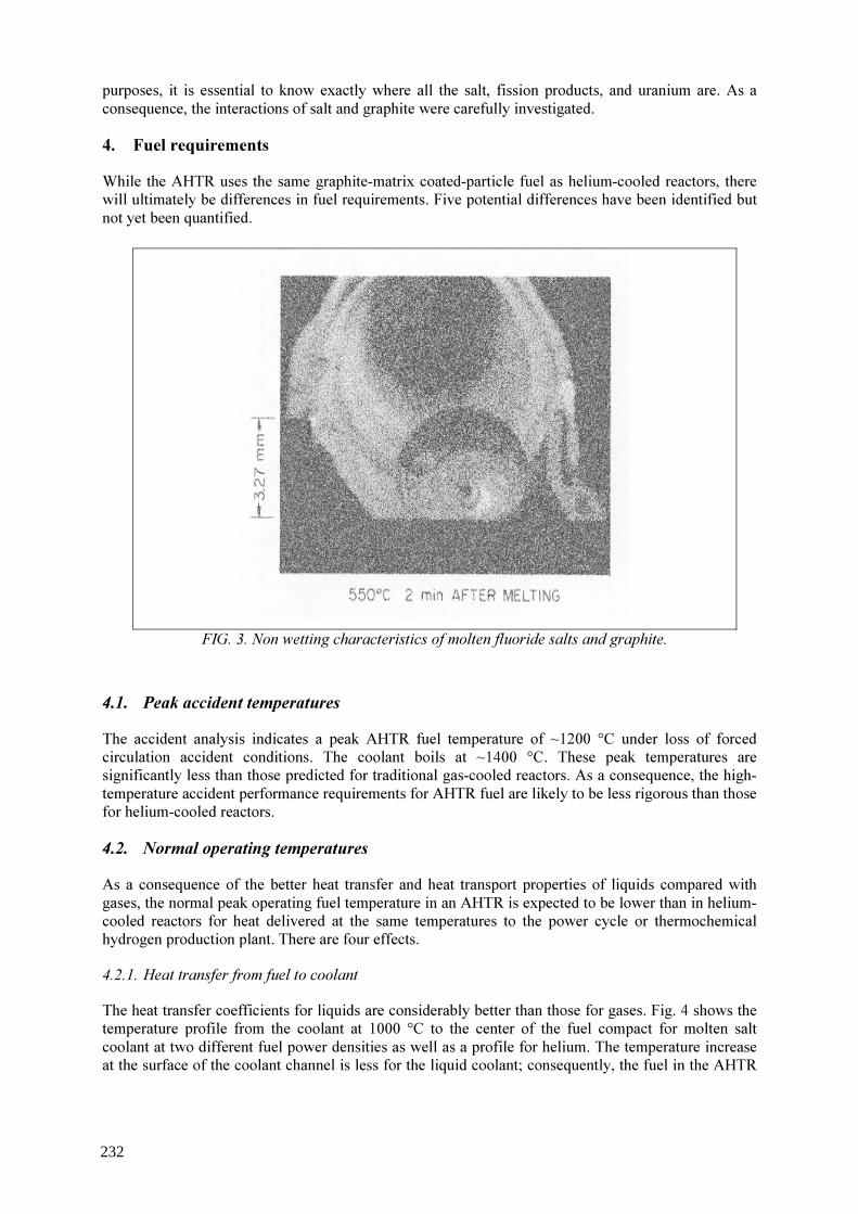
purposes, it is essential to know exactly where all the salt, fission products, and uranium are. As a consequence, the interactions of salt and graphite were carefully investigated. 4. Fuel requirements While the AHTR uses the same graphite-matrix coated-particle fuel as helium-cooled reactors, there will ultimately be differences in fuel requirements. Five potential differences have been identified but not yet been quantified.
FIG. 3. Non wetting characteristics of molten fluoride salts and graphite. 4.1. Peak accident temperatures The accident analysis indicates a peak AHTR fuel temperature of ~1200 °C under loss of forced circulation accident conditions. The coolant boils at ~1400 °C. These peak temperatures are significantly less than those predicted for traditional gas-cooled reactors. As a consequence, the high-temperature accident performance requirements for AHTR fuel are likely to be less rigorous than those for helium-cooled reactors. 4.2. Normal operating temperatures As a consequence of the better heat transfer and heat transport properties of liquids compared with gases, the normal peak operating fuel temperature in an AHTR is expected to be lower than in helium-cooled reactors for heat delivered at the same temperatures to the power cycle or thermochemical hydrogen production plant. There are four effects. 4.2.1. Heat transfer from fuel to coolant The heat transfer coefficients for liquids are considerably better than those for gases. Fig. 4 shows the temperature profile from the coolant at 1000 °C to the center of the fuel compact for molten salt coolant at two different fuel power densities as well as a profile for helium. The temperature increase at the surface of the coolant channel is less for the liquid coolant; consequently, the fuel in the AHTR
232

operates at lower temperatures for the same coolant exit temperatures as in a comparable gas-cooled reactor. Also shown is the temperature jump from the graphite matrix to the fuel compact. 4.2.2. Power peaking The power density in a reactor core will vary with position. As a consequence, there will be differences in the coolant temperatures exiting different coolant channels. The exit coolant temperatures from the hottest coolant channels will be significantly above the average core exit temperature with corresponding higher fuel temperatures near these coolant channels. Reducing the differences between peak and average coolant temperatures exiting the reactor core reduces the peak fuel temperature for any given average reactor-exit coolant temperature. There are many methods to reduce this temperature difference. The physical properties of liquids compared to gases helps reduce the differences between peak and average coolant temperatures exiting the core under normal and accident conditions. The viscosity of helium increases with temperature as T1/2. Consequently, as the temperature of the helium increases, the gas viscosity increases, the resistance to fluid flow increases, and the flow in the coolant channel decreases. The fuel channels with the highest power densities have lower gas flows and higher helium coolant-channel exit temperatures. In contrast, the viscosity [9] of molten salts decreases with temperature [A × exp (B/T)]. Consequently, as the temperature of the molten salt increases, the liquid viscosity decreases and the flow in the coolant channel increases. The fuel channels with the highest power levels have the highest molten salt flows. This behavior reduces the temperature differences between the coolant exiting the hottest fuel channels and the average fuel channels. 4.2.3. Temperature of delivered heat Liquid-cooled reactors deliver most of their heat at temperatures close to the reactor coolant exit temperature while gas-cooled reactors deliver their heat over a large temperature range (Fig. 5). Gas-cooled systems have higher pumping costs relative to liquid-cooled systems. As a consequence, practical designs of gas-cooled reactors - such as the General Atomics helium-cooled gas turbine-modular helium reactor (GT-MHR) and the British carbon dioxide-cooled advanced gas reactor (AGR)─have large temperature changes across the reactor core and deliver their heat to the power cycle over a large temperature range. In contrast, liquid-cooled reactors such as the French sodium-cooled super phoenix liquid-metal fast-breeder reactor (LMFBR) and pressurized-water reactors (PWRs) have low pumping costs and are designed to deliver their heat from the reactor core to the power cycle over a small temperature range.
233

FIG. 4. Temperature profile from the coolant to fuel compact centerline.
For some applications, such as thermochemical production of hydrogen, much of the heat must be delivered above a specific temperature to drive chemical reactions. For any required temperature of delivered heat, molten salt cooling allows for lower reactor-core exit cooling temperatures than in a gas-cooled reactor.
980
1000
1020
1040
1060
1080
1100
1120
1140
1160
0 0.2 0.4 0.6 0.8 1 1.2 1.4 1.6 1.8 2
Distance (cm)
Temp
eratu
re (�C)
fuel compactcoolant channel
Temperature Profile at CoreOutlet for Average Channel
LiF-BeF2(600 MW, 6.6 W/cc)
Helium (600 MW, 6.6 W/cc)
LiF-BeF2(2400 MW, 8.3 W/cc)
MHTGR → graphitegraphite fuel compact
AHTR →coolant channel
Coolant ChannelCenterline
Fuel CompactCenterline
234

FIG. 5. Temperatures of delivered heat for different reactors.
If one compares a helium-cooled and a molten-salt-cooled high-temperature reactor, a helium cooled reactor (the GT-MHR) with a peak temperature of 850 °C delivers its average heat at the same temperature as a molten-salt-cooled AHTR with a peak coolant temperature of 750 °C. This implies that for any given peak temperature, the AHTR will have substantially higher efficiency that the gas-cooled reactor with the same peak temperatures. Alternatively, for the same efficiency the AHTR can operate at lower peak temperatures. 4.2.4. Heat exchanger losses For hydrogen production, an intermediate heat transport loop will be used to isolate the reactor from the hydrogen production facility. As shown earlier, molten salts (liquids) have superior heat transfer characteristics compared with those for helium (gases). As a consequence, the temperature drops across intermediate heat exchangers will be less and thus the peak reactor temperature will be lower for heat delivered at any given temperature to a thermochemical hydrogen production plant or power cycle. 4.3. Fuel quality
Fuel quality requirements are determined by operational and accident requirements. In an AHTR, the molten salt provides a major barrier to the release of radionuclides. Extensive studies [4] during the operation of the molten salt reactor experiment showed that only the noble gases (Xe, Kr) and tritium are released to the cover gas. Most fission products are dissolved in the molten salt (CsF, SrF2, BeI2) although some exist as metals and tend to deposit on metallic surfaces (Ag and others). This barrier to the release of radionuclides reduces the fuel quality requirements.
GT-MHR
0
800
1000
Peak Coolant Temperature Delivered Heat
Coolant Return Temperature
LiquidGas
Temp
eratur
e (�C)
Average Temperature of Delivered Heat
PWR
LMFBRAGR
200
400
600AHTR(Lower Temperature)
750�C
850�C VHTR(Molten Salt Cooled )
VHTR(He Cooled )
GT-MHR
0
800
1000
Peak Coolant Temperature Delivered Heat
Coolant Return Temperature
LiquidGas
Temperature (�C)
Average Temperature of Delivered Heat
PWR
LMFBRAGR
200
400
600AHTR(Lower Temperature)
750�C
850�C VHTR(Molten Salt Cooled )
VHTR(He Cooled )
oC
oC
(o C)
235

For helium-cooled reactors, the fuel quality requirements depend upon the safety strategy. If the fuel is to be the primary barrier to prevent release of radionuclides to the environment under accident conditions, there are stringent fuel reliability requirements. Under such circumstances, a low-failure-fraction fuel, only about 1 particle in ~100 000, is required to meet normal operation or accident conditions and still meet the regulatory requirements. The most mobile radioactive species are Ag-110m, Cs, I, and Sr. The controlling isotopes for site-boundary release are Cs and I while Ag-110m tends to controls the maintenance dose [10,11]. 4.4. Power density The preconceptual AHTR designs have assumed fuel power densities (8.3 watts/cm3) similar to those of traditional helium-cooled reactors. However, the heat transfer capabilities of the molten salt coolant are superior to those of helium. As a consequence, the peak fuel temperatures during normal operation are 100 to 200 °C lower than for a comparable gas-cooled reactor. Economic incentives to reduce the reactor core size and thus lower plant capital cost and refueling times are substantial. As such, there are strong economic incentives to increase fuel power densities, which will, in turn, increase the thermal gradient between the centerline fuel temperature and the coolant channel. 4.5. Fuel geometry Both refueling times and neutronics potentially constrain reactor fuel geometry. Reducing these constraints may impose added requirements on the fuel. Reactor refueling times depend upon the time to shut down the reactor (including temperature cooldown), move the fuel elements, and restart the reactor. While the first and last steps are somewhat independent of the reactor size, the middle step depends upon the number of fuel assemblies. If the AHTR uses the traditional prismatic fuel assemblies, the number of fuel elements in the core could be up to four times the number of fuel assemblies in an MHTGR because the power output is four times larger. Strong economic incentives exist to reduce the number of fuel assemblies and modify the geometry to minimize refueling times. Methods to reduce the refueling times include doubling the length of the fuel block, and thus reducing by a factor of two the number of fuel assemblies that must be handled; increasing fuel burnup; and changing the geometry, such as fuel assemblies with the height of the reactor core (similar to the Peach Bottom gas-cooled reactor). Neutronic studies are underway to optimize reactor core performance. Alternative distributions of fuel and coolant holes in the graphite block are being considered to improve core performance. These may or may not place additional geometric constraints on the fuel. 5. Conclusions The AHTR is a second category of high-temperature reactor that uses graphite-matrix coated-particle fuel. The distinguishing technical characteristic is the use of a low-pressure molten-salt coolant rather than helium. Using a low-pressure liquid coolant enables the construction of large passively safe high-temperature reactors. The AHTR is a new reactor concept that is early in its development. Preliminary studies indicate that the minimum requirements for fuel performance (peak accident temperatures, peak operating temperatures, and fuel failure fraction) will be significantly less than for helium-cooled reactors. These factors may reduce fuel development requirements for first-generation AHTRs. However, strong economic incentives exist to operate the fuel at higher power densities than in helium-cooled reactors and more demanding requirements may be placed on the fuel assembly geometry.
236

REFERENCES [1] FORSBERG, C.W., PICKARD, P.S., PETERSON, P.F., “Molten-Salt-Cooled Advanced
High-Temperature Reactor for Production of Hydrogen and Electricity,” Nucl. Technol., 144, December (2003) 289-302.
[2] FORSBERG, C.W., et al., Status of Preconceptual Design of the Advanced High-Temperature Reactor, ORNL/TM-2004/104, May (2004).
[3] FORSBERG, C.W., PETERSON, P.F., PICKARD, P., 2004, “Maximizing Temperatures of Delivered Heat from the Advanced High-Temperature Reactor,” 2004 International Congress on Advances in Nuclear Power Plants (ICAPP ’04), Embedded International Topical Meeting 2004 American Nuclear Society Annual Meeting, Pittsburg, June 13-17, (2004).
[4] NUCL APPL. TECHNOL, February 1970, 8, 2 (Entire issue). ORNL, 1964, Molten Salt Reactor Program Semiannual Progress Report for the Period Ending January 31, 1964, ORNL 3626, Oak Ridge National Laboratory, Oak Ridge, Tennessee, USA, (1964).
[5] MCCOY, H.E., MCNABB, B., Postirradiation Examination of Materials from the MSRE, ORNL/TM-4174, Oak Ridge National Laboratory, Oak Ridge, Tennessee, December (1972).
[6] ROSENTHAL, M.W., BRIGGS, R.B., KASTEN, P.R., 1969, Molten-Salt Reactor Program Semiannual Progress Report for Period Ending August 31, 1968, ORNL-4344, Oak Ridge National Laboratory, Oak Ridge, Tennessee, (1968)
[7] BRIGGS, R.B., 1963, Molten Salt Reactor Program Semiannual Progress Report for Period Ending July 31, 1963, ORNL-3529, Oak Ridge National Laboratory, Oak Ridge, TN, (1963)
[8] FONTANA, A., WINARD, R., Etude de La Mouillability Du Graphite Par Differents Melanges NaF-ZrF4-ZrO2 Fondus en Presence de Diverses Atmopsheres Gazeuses, J. of Nucl Materials, 35, (1970) pp. 87–93.
[9] DEWITT, R., WITTENBURG, L.J., CANTOR, S., “Viscosity of Molten NaCl, NaBF4, and KBF4,” Phys. and Chem. of Liquids, vol. 4, Issue 2 & 3, (1974) p.113–123.
[10] MOORMANN, R., SCHENK, W., VERFONDERN, K., “Source Term Estimate for Small-Sized HTRs: Status and Further Needs, Extracted from German Safety Analysis,” Nucl. Techno., 135, (3), (2001)pp.183–193.
[11] INTERNATIONAL ATOMIC ENERGY AGENCY, Fuel Performance and Fission Product Behavior in Gas-Cooled Reactors, IAEA TECDOC-978, Vienna, November (1997).
237
The international GT–MHR fuel development program
N. Kodochigova, Yu.P. Sukhareva, N. Ponomarev-Stepnoyb, Yu. Degaltsevb, V. Novikovc, I. Kadarmetovc, V. Makarovc, V. Sulaberidzed, A. Chernikove, D. McEachern, R. Noren f
a b c d e f
JSC Afrikantov OKBM, Nizhny Novgorod, Russian Federation RRC KI, Moscow, Russian Federation VNIINM, Moscow, Russian Federation NIIAR, Russian Federation SIA-Lutch, Podolsk, Moscow Region, Russian Federation General Atomics, San Diego, California, USA
Abstract: The presentation described the programme to develop coated particle fuel for disposal of excess weapons grade plutonium using a gas turbine modular helium reactor. The fuel has quality requirements similar to those of commercial coated particle fuel with equivalent irradiation service conditions. The program, which is being conducted by a Russian nuclear laboratory and other Russian nuclear organizations, is a joint effort of the Federal Agency for Atomic Energy of the Russian Federation and the National Nuclear Security Administration of the United States of America. Current program activities are focusing on the completion of a fuel fabrication bench-scale facility (BSF) at the Bochvar Institute. The facility will be used to fabricate plutonium coated particle fuel and to prepare reactor equipment and irradiation samples for testing the fuel at the Research Institute for Atomic Reactors. The BSF program involves fabrication process development for both a reference fuel type and an alternative (backup) fuel type. The reference fuel involves a TRISO coated 200 µm diameter kernel consisting of a mixture of PuO2 and Pu2O3 with an O/Pu ratio of ≤ 1.7. The alternative fuel types being considered are based on plutonium oxides diluted with inert or fertile materials and a ZrC layer as the principle fission product barrier. Both fuel types will be included in the initial irradiation testing and accident condition testing programs which will be used to make the final choice between the fuel types. An overview of the two fuel designs and specifications, the manufacturing process flow diagrams and the in-service requirements are given in the paper. Construction of the BSF and process equipment is well advanced with initial operation scheduled for the summer of 2004. 1. Introduction The design of the gas-turbine modular helium reactor (GT-MHR) is based on rendering the excess weapons-grade plutonium useless for weapons by destroying a large fraction of the fissionable plutonium in a single pass through the reactor. This requires a fuel that can achieve a high burnup of fissionable plutonium in case of fission product release under normal operating conditions and in design-basis accidents at the level allowed for modular reactors with direct gas-turbine cycle. The program to develop coated particle fuel for disposal of excess Russian weapons plutonium is being carried out by Russian nuclear labs and industrial organizations with support from US specialists at General Atomics and Oak Ridge National Laboratory. Minatom of Russia and the US National Nuclear Security Agency each provide 50% of the funds for the program. Because of the limited experience with high-burnup plutonium fuel, both a reference and alternate fuels are being developed and tested prior to a final selection of the fuel for the initial core for the first GT-MHR module. The development program includes fuel design and performance modeling, process development, and irradiation and accident testing. The sequence of these activities and their interrelationships are shown in Fig. 1.
238

The current program activities are focused on development of the technology for the fuel and the power conversion unit. The main goals of the on-going GT-MHR fuel development program are:
• Develop the technology to manufacture fuel for the GT-MHR; and • Qualify fuel for use in the GT-MHR.
Provide the fuel data base to design, license and operate the fuel fabrication facility and the prototype module of the GT-MHR.
FIG. 1. Fuel development program testing sequence. 2. Program organization Afrikantov Experimental Machine Building Design Bureau OKBM {now called as JSC Afrikantov OKBM} implements overall control of GT-MHR program. Bochvar All-Russian Scientific Research Institute for Inorganic Materials (VNIINM) has technical responsibility for fuel development. Russian Research Centre "Kurchatov Institute" (RRC-KI) and Industrial Association Lutch together with VNIINM develop fuel technology. Irradiation, post-irradiation examinations and testing for safety validation will be conducted at NIIAR. It is planned to locate the prototype reactor module fuel fabrication facility near prototype module site at the Siberian Chemical Combine (SCC). Almost all Russian personnel of the various organizations participating in fuel development were involved in coated particle fuel development program that was carried out in Russia from the mid-60s to the early 90s. 3. Fuel In the conceptual and preliminary design phases of the GT-MHR project, a reference fuel design was developed and the need for including work on alternate fuel designs in the plan to reduce technical and programmatic risks was identified. Both a reference fuel and an alternate backup fuel will be carried in the early process development and in initial irradiations and accident simulation tests before the final fuel selection is made. The reference fuel is TRISO-coated, 200-µm diameter kernels consisting of a mixture of PuO2 and Pu2O3 with an O/Pu atom ratio of <1.7. This design is based on fuel particles of this type irradiated to high burnup in a test element in Peach Bottom I in the 1970s. Characteristics of the reference fuel are shown in Table 1. Alternate fuels being considered are plutonium oxides diluted with inert or fertile materials and use of ZrC in the coatings. The fuel for the GT-MHR has quality requirements similar to those of commercial coated particle fuels and the GT-MHR core is designed to subject the fuel to in-service irradiation conditions similar to those of the commercial GT-MHR designs.
ProcessDevelopment
SamplePreparation
SampleCharacterization
Irradiation
AccidentSimulation
Post-IrradiationExamination
Fuel Database
Fuel DesignModeling
Specifications
239
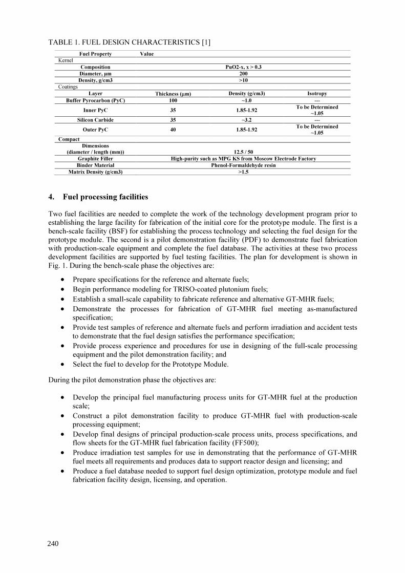
TABLE 1. FUEL DESIGN CHARACTERISTICS [1] Fuel Property Value
Kernel Composition PuO2-x, x > 0.3 Diameter, µm 200 Density, g/cm3 >10
Coatings Layer Thickness (µm) Density (g/cm3) Isotropy
Buffer Pyrocarbon (PyC) 100 ~1.0 --- Inner PyC 35 1.85-1.92 To be Determined
~1.05 Silicon Carbide 35 ~3.2 --- Outer PyC 40 1.85-1.92 To be Determined
~1.05 Compact
Dimensions (diameter / length (mm))
12.5 / 50
Graphite Filler High-purity such as MPG KS from Moscow Electrode Factory Binder Material Phenol-Formaldehyde resin
Matrix Density (g/cm3) >1.5 4. Fuel processing facilities Two fuel facilities are needed to complete the work of the technology development program prior to establishing the large facility for fabrication of the initial core for the prototype module. The first is a bench-scale facility (BSF) for establishing the process technology and selecting the fuel design for the prototype module. The second is a pilot demonstration facility (PDF) to demonstrate fuel fabrication with production-scale equipment and complete the fuel database. The activities at these two process development facilities are supported by fuel testing facilities. The plan for development is shown in Fig. 1. During the bench-scale phase the objectives are: • Prepare specifications for the reference and alternate fuels; • Begin performance modeling for TRISO-coated plutonium fuels; • Establish a small-scale capability to fabricate reference and alternative GT-MHR fuels; • Demonstrate the processes for fabrication of GT-MHR fuel meeting as-manufactured
specification; • Provide test samples of reference and alternate fuels and perform irradiation and accident tests
to demonstrate that the fuel design satisfies the performance specification; • Provide process experience and procedures for use in designing of the full-scale processing
equipment and the pilot demonstration facility; and • Select the fuel to develop for the Prototype Module.
During the pilot demonstration phase the objectives are: • Develop the principal fuel manufacturing process units for GT-MHR fuel at the production
scale; • Construct a pilot demonstration facility to produce GT-MHR fuel with production-scale
processing equipment; • Develop final designs of principal production-scale process units, process specifications, and
flow sheets for the GT-MHR fuel fabrication facility (FF500); • Produce irradiation test samples for use in demonstrating that the performance of GT-MHR
fuel meets all requirements and produces data to support reactor design and licensing; and • Produce a fuel database needed to support fuel design optimization, prototype module and fuel
fabrication facility design, licensing, and operation.
240
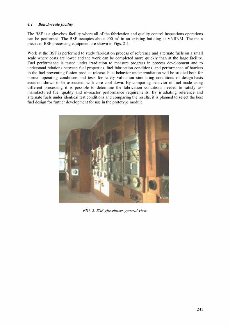
4.1 Bench-scale facility The BSF is a glovebox facility where all of the fabrication and quality control inspections operations can be performed. The BSF occupies about 900 m2 in an existing building at VNIINM. The main pieces of BSF processing equipment are shown in Figs. 2-5. Work at the BSF is performed to study fabrication process of reference and alternate fuels on a small scale where costs are lower and the work can be completed more quickly than at the large facility. Fuel performance is tested under irradiation to measure progress in process development and to understand relations between fuel properties, fuel fabrication conditions, and performance of barriers in the fuel preventing fission product release. Fuel behavior under irradiation will be studied both for normal operating conditions and tests for safety validation simulating conditions of design-basis accident shown to be associated with core cool down. By comparing behavior of fuel made using different processing it is possible to determine the fabrication conditions needed to satisfy as-manufactured fuel quality and in-reactor performance requirements. By irradiating reference and alternate fuels under identical test conditions and comparing the results, it is planned to select the best fuel design for further development for use in the prototype module.
FIG. 2. BSF gloveboxes general view.
241

FIG. 3. Kernel sintering furnace.
FIG. 4. Coating equipment in glove box and cut-away sketch showing coater internals coater.
242
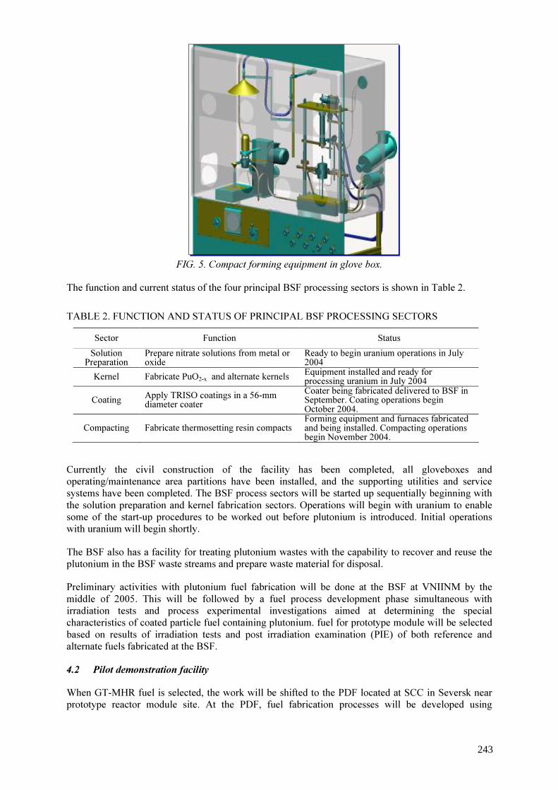
FIG. 5. Compact forming equipment in glove box. The function and current status of the four principal BSF processing sectors is shown in Table 2.
TABLE 2. FUNCTION AND STATUS OF PRINCIPAL BSF PROCESSING SECTORS Sector Function Status Solution Preparation
Prepare nitrate solutions from metal or oxide
Ready to begin uranium operations in July 2004
Kernel Fabricate PuO2-x and alternate kernels Equipment installed and ready for processing uranium in July 2004
Coating Apply TRISO coatings in a 56-mm diameter coater
Coater being fabricated delivered to BSF in September. Coating operations begin October 2004.
Compacting Fabricate thermosetting resin compacts Forming equipment and furnaces fabricated and being installed. Compacting operations begin November 2004.
Currently the civil construction of the facility has been completed, all gloveboxes and operating/maintenance area partitions have been installed, and the supporting utilities and service systems have been completed. The BSF process sectors will be started up sequentially beginning with the solution preparation and kernel fabrication sectors. Operations will begin with uranium to enable some of the start-up procedures to be worked out before plutonium is introduced. Initial operations with uranium will begin shortly. The BSF also has a facility for treating plutonium wastes with the capability to recover and reuse the plutonium in the BSF waste streams and prepare waste material for disposal. Preliminary activities with plutonium fuel fabrication will be done at the BSF at VNIINM by the middle of 2005. This will be followed by a fuel process development phase simultaneous with irradiation tests and process experimental investigations aimed at determining the special characteristics of coated particle fuel containing plutonium. fuel for prototype module will be selected based on results of irradiation tests and post irradiation examination (PIE) of both reference and alternate fuels fabricated at the BSF. 4.2 Pilot demonstration facility When GT-MHR fuel is selected, the work will be shifted to the PDF located at SCC in Seversk near prototype reactor module site. At the PDF, fuel fabrication processes will be developed using
243

production-scale equipment. Fuel made on the full-scale equipment will be tested to obtain needed fuel performance and fission product release data that will enable further testing in the GT-MHR prototype module. The PDF will be established as a portion of the production line of the fuel fabrication facility (FF500) with capacity of 500-kg Pu/year, eventually used to produce fuel for the GT-MHR Prototype Module. As seen in Fig. 6, the results from testing BSF-made fuel will be used to justify the license for construction of the pilot demonstration facility, that is scheduled for 2009. 5. Fuel irradiation tests and post-irradiation examination Fuel irradiation and accident testing will begin with fuel fabricated at the BSF. Initial tests will be done with uranium fuel to test the coating and compacting processes as well as the irradiation and accident testing facilities before introducing plutonium. Initial core operation options include the possibility of running the initial core to a burnup lower than the eventual peak value. Therefore, the initial plutonium tests will use BSF-fabricated reference and alternate fuels and they will be irradiated first to a moderate burnup level (∼36% FIMA) and in subsequent tests to peak burnup (~70% FIMA) and peak fast neutron fluence. Irradiation and accident testing results will be used to refine the fuel specification and the performance requirements. The testing requirements are based on the core design developed during the preliminary design phase. requirements for fuel testing environment and for fission product retention are shown in Table 3: TABLE 3. FUEL OPERABILITY REQUIREMENTS [1]
Operating Parameter Value - Mean core residence time, effective full-power days ~ 750 - Fuel burn-up: • mean, MW⋅day/kg total Pu • maximum, MW⋅day/kg
640 ≤ 930
- Power of fuel compact: • mean, kW • maximum, kW
0.2 0.6
- Maximum fluence of neutrons at (Е > 0.18 MeV), n/m2 4⋅1025 - Maximum fuel temperature: • under the normal operation, • design-basis accidental conditions, (100 hr)
1250 0C 1600 0C
Requirement Value - Pu contaminated fuel compact ≤ 10-5 - CP with a failed SiC in the produced FC ≤ 5⋅10-5 - CP with failed coatings normal operation conditions ≤ 1 10-4 FP release (R/B) normal operation conditions: Xe-133 ≤ 5⋅10-5 I-131 ≤ 2⋅10-5 Cs-134, Cs-137 ≤ 1⋅10-4 Ag-110m ≤ 1⋅10-3 FP release (R/B) design-basis accidental conditions:
244

Xe-133 ≤ 5⋅10-4 I-131 ≤ 2⋅10-4 Cs-134, Cs-137 ≤ 2⋅10-4 Ag-110m ≤ 1⋅10-2
Fuel irradiation tests will conduct at NIIAR research reactors SM-3 and RBT-6. The main characteristics of these reactors and the test parameters achieved are presented in Table 4. TABLE 4. CHARACTERISTICS OF NIIAR REACTORS [2]
Capacity factors for the NIIAR test reactors are: In SM-3 reactor – 0.6 In RBT-6 reactor – 0.7 Both SM-3 and RBT-6 have eight channels appropriate for testing of GT-MHR fuel. Up to 3 individually controlled and sampled ampoules can be irradiated in these channels. The purge gas and temperature control gas systems of these reactors are arranged so that a maximum of 20 ampoules can be irradiated simultaneously. The capability to test a number of fuel samples simultaneously will reduce the time and cost to carry out the required irradiation test program. To achieve neutron fluxes more representation of the GT-MHR core, neutron screens are planned for the various positions in the SM-3 reactor as shown in Table 4. Some devices available with various capabilities were developed for irradiation tests. The devices all have provisions for purge gas to measure fission gas release to birth ratios during testing, thermocouples and temperature control gas mixtures. Ampoules also have the possibility of using small, sealed ("piggy-back") samples and some can be fitted with flux monitors. The irradiation test matrix planned for BSF-made fuel is presented in Table 5. Table 6 presents the matrix of safety tests to demonstrate fuel accident performance.
ValueSM-3
ParameterRequired byGT-MHRProject
Channels of 1-st reflectorrow with Cdscreen of 1-2mm thickness
Channels of 2-ndreflector row withHf screen of 4mm
thickness
Channels of 2-ndreflector row withHf screen of 2 mm
thickness
RBT-6
Core height, mm 350 350 350 350Diameter of channels, mm 64 64 64 64
Number of channels 4 4 4 8Number of ampoule/channel 3 3 3 1/3Number of compacts/ ampoule 4 4 4 12/(300 CP)
Fuel compact power, kW• average• maximal
0.20.6
0.6-0.45 0.3-0.15 0.6-0.45 0.34-0.15
Max. full neutron flux, x1014n/cm2s 2.8 ∼15 3.1 5.4 2.0
Max. fast (E>0.18 MeV) neutronflux, x1014 n/cm2s 0.6 3.1 0.65 0.62 0.53
Time needed for full burnup(70% FIMA), effective
days/calendar750/ 300/500 710/1180 360/600 800/1140
Time needed for full fast neutronfluence (4x1025 n/m2), effective
days/calendar750/ 150/250 710/1180 710/1180 900/1290
245
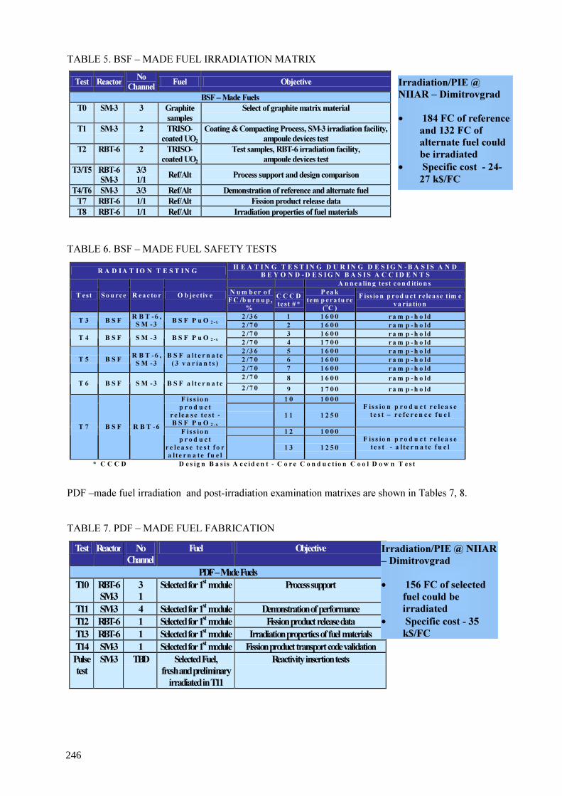
TABLE 5. BSF – MADE FUEL IRRADIATION MATRIX TABLE 6. BSF – MADE FUEL SAFETY TESTS PDF –made fuel irradiation and post-irradiation examination matrixes are shown in Tables 7, 8. TABLE 7. PDF – MADE FUEL FABRICATION
Test Reactor No Channel Fuel Objective
BSF – Made Fuels T0 SM-3 3 Graphite
samples Select of graphite matrix material
T1 SM-3 2 TRISO-coated UO2
Coating & Compacting Process, SM-3 irradiation facility, ampoule devices test
T2 RBT-6 2 TRISO-coated UO2
Test samples, RBT-6 irradiation facility, ampoule devices test
T3/T5 RBT-6 SM-3
3/3 1/1 Ref/Alt Process support and design comparison
T4/T6 SM-3 3/3 Ref/Alt Demonstration of reference and alternate fuel T7 RBT-6 1/1 Ref/Alt Fission product release data T8 RBT-6 1/1 Ref/Alt Irradiation properties of fuel materials
Irradiation/PIE @ NIIAR – Dimitrovgrad • 184 FC of reference
and 132 FC of alternate fuel could be irradiated
• Specific cost - 24-27 k$/FC
R A D IA T IO N T E S T IN G H E A T IN G T E S T IN G D U R IN G D E S IG N -B A S I S A N D B E Y O N D -D E S IG N B A S I S A C C ID E N T S
A n n ea lin g test con d itio n s T est S o u rce R eac to r O b jectiv e N u m b er o f
F C /b u rn u p , %
C C C D test #*
P eak tem p era tu re
(oC ) F issio n p rod u ct re lease tim e
v ar ia tio n 2 /3 6 1 1 6 0 0 r a m p -h o ld T 3 B S F R B T -6 ,
S M -3 B S F P u O 2 -x 2 /7 0 2 1 6 0 0 r a m p -h o ld 2 /7 0 3 1 6 0 0 r a m p -h o ld T 4 B S F S M -3 B S F P u O 2 -x 2 /7 0 4 1 7 0 0 r a m p -h o ld 2 /3 6 5 1 6 0 0 r a m p -h o ld 2 /7 0 6 1 6 0 0 r a m p -h o ld T 5 B S F R B T -6 ,
S M -3 B S F a l t e r n a t e
( 3 v a r ia n t s ) 2 /7 0 7 1 6 0 0 r a m p -h o ld 2 /7 0 8 1 6 0 0 r a m p -h o ld T 6 B S F S M -3 B S F a l t e r n a t e 2 /7 0 9 1 7 0 0 r a m p -h o ld
1 0 1 0 0 0 F is s io n p r o d u c t
r e le a s e t e s t - B S F P u O 2 -x
1 1 1 2 5 0
F is s io n p r o d u c t r e le a s e t e s t – r e f e r e n c e fu e l
1 2 1 0 0 0 T 7 B S F R B T -6 F is s io n p r o d u c t
r e le a s e t e s t f o r a l t e r n a t e fu e l
1 3 1 2 5 0
F is s io n p r o d u c t r e le a s e t e s t - a l t e r n a te f u e l
* C C C D D e s ig n B a s i s A c c id e n t - C o r e C o n d u c t io n C o o l D o w n T e s t
Test Reactor No Channel
Fuel Objective
PDF – Made Fuels T10 RBT-6
SM-3 3 1
Selected for 1st module Process support
T11 SM-3 4 Selected for 1st module Demonstration of performance T12 RBT-6 1 Selected for 1st module Fission product release data T13 RBT-6 1 Selected for 1st module Irradiation properties of fuel materials T14 SM-3 1 Selected for 1st module Fission product transport code validation Pulse test
SM-3 TBD Selected Fuel, fresh and preliminary irradiated in T11
Reactivity insertion tests
Irradiation/PIE @ NIIAR – Dimitrovgrad • 156 FC of selected
fuel could be irradiated
• Specific cost - 35 k$/FC
246

TABLE 8. POST – IRRADIATION SAFETY TESTS
6. Fuel summary schedule According to the fuel development program schedule three options are being considered that include the startup of the first GT-MHR Prototype Module (Fig. 6): � The basic option: The beginning of 2016 upon completion of the PDF phase; � An accelerated option without an alternate fuel: The middle of 2015 when reference fuel made at
the PDF has demonstrated satisfactory performance to 36% FIMA; and � An accelerated option without and alternate fuel or PDF operation: In 2014 when reference fuel
made at the BSF has demonstrated satisfactory performance to 36% FIMA.
R A D I A T I O N T E S T I N G H E A T I N G T E S T I N G D U R I N G D E S I G N - B A S I S A N D B E Y O N D - D E S I G N B A S I S A C C I D E N T S
A n n e a lin g te s t c o n d itio n s T e s t S o u r ce R ea c to r O b je c tiv e N u m b e r o f
F C /b u r n u p , %
C C C D te s t # *
P e a k tem p e r a tu r e
( oC ) F iss io n p r o d u c t r e le a s e
t im e v a r ia tio n 2 / 3 6 1 4 1 6 0 0 r a m p - h o l d T 1 0 P D F R B T - 6 ,
S M - 3 S e l e c t e d P D F
f u e l 2 / 7 0 1 5 1 6 0 0 r a m p - h o l d 2 / 7 0 1 6 1 6 0 0 r a m p - h o l d 2 / 7 0 1 7 1 6 0 0 C o r e s im u la t i o n 2 / 7 0 1 8 1 7 0 0 r a m p - h o l d 2 / 7 0 1 9 1 8 0 0 r a m p - h o l d 2 / 7 0 2 0 1 6 0 0 r a m p - h o l d , a i r 2 / 7 0 2 1 1 6 0 0 r a m p - h o ld , m o i s t u r e
T 1 1 P D F S M - 3 S e l e c t e d P D F f u e l
1 8 / 0 ; 1 8 /7 0 B D B A -2 2 * * P u l s e t e s t s
2 3 9 0 0 2 4 1 1 0 0
F i s s i o n p r o d u c t r e l e a s e t e s t , h e l i u m
2 5 1 2 5 0 2 6 1 2 5 0 F i s s i o n p r o d u c t r e l e a s e
t e s t , a i r T 1 2 P D F R B T - 6
F i s s i o n p r o d u c t
r e l e a s e t e s t - S e l e c t e d P D F
f u e l 2 7 1 2 5 0 F i s s i o n p r o d u c t r e l e a s e t e s t , m o i s t u r e
2 8 1 0 0 0 2 9 1 2 5 0 3 0 1 6 0 0 T 1 4 P D F S M - 3
V a l i d a t i o n o f f i s s i o n
p r o d u c t r e l e a s e c o d e 3 1 1 7 0 0
C o d e v a l i d a t i o n
* C C C D D e s ig n B a s i s A c c i d e n t - C o r e C o n d u c t i o n C o o l D o w n T e s t * * B D B A B e y o n d D e s i g n B a s i s A c c i d e n t R a p i d R e a c t i v i t y I n s e r t i o n T e s t
247
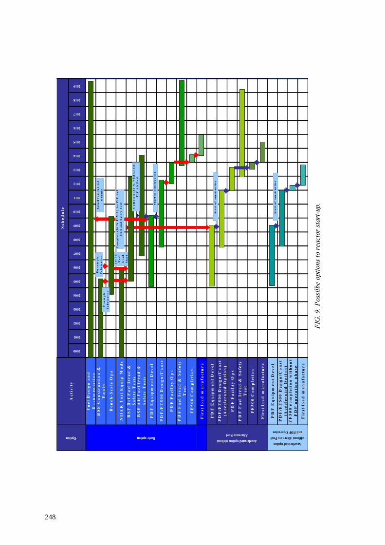
FIG.
9. Po
ssilbe
optio
ns to
reacto
r star
t-up.
Fuel Design an
d Docum
entatio
nBS
F Con
stru
ction &
Equip
Benc
h-Sc
ale Ops
NIIAR Test E
quip M
ods
BSF Ref Fue
l Irrad
&
Safety Tests
BSF Alt Fu
el Ir
rad &
Safety Tests
PDF Eq
uipm
ent D
evel
PDF/FF
500 Design/Con
st
PDF Fa
cility Ops
PDF Fu
el Ir
rad & Safety
Test
FF50
0 Com
pletion
First loa
d man
ufacture
PDF Eq
uipm
ent D
evel
PDF/FF
500 Design/Con
st
(Accelerated
Option)
PDF Fa
cility Ops
PDF Fu
el Ir
rad & Safety
Test
FF50
0 Com
pletion
First loa
d man
ufacture
PDF Eq
uipm
ent D
evel
PDF/FF
500 Design/Con
st
(Accelerated
Option)
FF50
0 completion with
out
FDP op
eration ph
ase
First loa
d man
ufacture
Option Basic option Accelerated option without Alternate Fuel
Accelerated option without Alternate Fuel and PDF Operation
2004
2003
2013
2012
2011
Activity
2009
2008
2007
2006
2000
2001
2002
Sche
dule
2005
2010
2019
2018
2017
2016
2015
2014
1st P
u Fu
el
Irrad
Start
Select fu
el fo
r 1st
mod
ule
Com
plete (36 % FIM
A) 1
st
PIE Alt Fu
el
Start o
f con
struction
Start o
f con
struction
Start o
f con
struction
Pu sa
mple
Fabrication
U sa
mple
Fabrication
Com
plete (36 % FIM
A) 1
st PIE
Ref
Fuel and
Safety Test
248

REFERENCES
[1] KODOCHIGOV, N.G., KUZAVKOV, N.G., SUKHAREV, Yu.P., et al., The Gas Turbine-Modular Helium Reactor Program for Efficient Disposition of Weapons Plutonium, Proceedings of IAEA Technical Committee Meeting on ‘High temperature gas cooled reactor applications and future prospects’ held in Petten, The Netherlands, 10-12 Nov. (1997), report ECN-R--98-004; CONF-9711197, Netherlands Energy Research Foundation ECN, Petten, Netherlands, (1998) https://www.etde.org/etdeweb/details.jsp?osti_id=314492
[2] POKROVSKY, A., KAZAKOV, V., MELDER, R., Reactors and within hot cell facilities of RIAR for substantiation of GT-MHR fuel efficiency, 19-th international meeting “GT-MHR fuel development program”, July 30 – August 3, 2001, RRC KI, Moscow (2001).
249

Images of HTGR fuel cycle and view points important
Y. Tsuchie Research Association of HTGR Plant (RAHP) The Japan Atomic Power Co. (JAPC), Tokyo, Japan
Abstract. Small and modular high temperature gas cooled reactor (HTGR)s and very high temperature reactor (VHTR)s, capable of supplying nuclear heat of about 1000 °C, and then generating electricity and hydrogen with high efficiency, are now very highly evaluated as next generation nuclear system from view points of energy security and global environment. Technologies for their fuel cycles, typically ‘recycle’ or ‘once-through’ are already or being available. Such HTGRs and their fuel cycles, however, are necessary to be internationally and carefully designed and managed from view points of nuclear non-proliferation, etc., because of graphite-moderated system and expected dispersed instalment in global scale, and here ‘Regional fuel centres’ differentiating such fuel cycles are proposed. And now is the timing for start of such international measures.
1. Introduction The world is now faced with serious problems of (1) energy shortage and (2) global warming, due to the population growth and remarkably rapid economic growth, as seen in recent Asian countries, China in particular. Nuclear energy is considered to be one of the effective and practical solutions for the problems, from view points of (a) production scale, (b) sustainability, and (c) cleanliness (viz., little or no emission of green-house gases). Electricity and heat supplies by nuclear reactor plant systems, small (100-300 MWe equivalent) and modular type of high temperature gas cooled reactor (HTGR) operating at 850-950 °C and very high temperature reactor (VHTR) operating at 1000 °C or above, in particular, are now internationally highly evaluated, among various candidates for next generation nuclear systems as seen in IAEA’s ‘International Project on Innovative Nuclear Reactors and Fuels (INPRO)’ or US-DOE’s ‘Generation Ⅳ nuclear’ (Gen.Ⅳ) reactor program, to be promising, from view points of: -Electricity production, with high efficiency; -Direct cycle with gas turbine; -Nuclear hydrogen production, with high efficiency; -Clean energy ( namely hydrogen) by clean (e.g., nuclear) system for hydrogen cars and stationary batteries; -Other forms of nuclear heat uses, like process heat supply, regional heat supply, sea-water desalination for industry, agriculture and/or drinking water, etc.; -Development flexibility; -Flexible energy supply planning by adjusting to the changing or variable demands in timing, scale and location, due to its small unit capacity; -Fuel cycle flexibility; -Thorium (Th) as well as uranium (U) and plutonium (Pu) can be used as fuel or fertile materials; -Recycle’ or ‘once-through’ fuel cycle as option, as described in Section 2.; -Global marketability;
250
- Potential market in both developed and developing countries; and - Electricity and a wide range of heat uses like hydrogen generation. And now such HTGRs and hydrogen production systems by nuclear energy (viz., by nuclear hydrogen production) are already under development or in preparation in Japan, China, South Africa, US, Russia, Europe, etc. towards demonstration in early 2010’s, as follows ;
- Test Reactor Programs; High temperature engineering test reactor (HTTR) (Japan) for safety demonstration and innovative technology developments, including nuclear hydrogen production, or high temperature reactor test module (HTR-10) (China) for safety demonstration and multi-purpose heat use development.
- Demonstration / 1st commercial reactor programs; Pebble bed modular reactor (PBMR) (South Africa) for electricity generation (400 MWt/165 MWe) aiming at operational start in 2010, or gas turbine modular helium reactor (GT-MHR) (US-Russia) for burning of surplus weapon grade Pu (WGPu), electricity generation and heat uses (600 MWt/280 MWe). Gas turbine modular helium reactor (GT-MHR) (US) for civil use (with U fuel core), Gas turbine high temperature reactor (GTHTR-300) (Japan) for electricity, gas turbine high temperature reactor co-generation (GTHTR-300C) (Japan) for electricity and hydrogen co-generation) (600 MWth), High temperature reactor prototype module (HTR-PM) (China) for electricity (and heat uses) (150 MWth), or Idaho program (US) for electricity & hydrogen co-generation (300-600 MWth) aiming at operational start in 2010-2016.
Based on such test and demonstration reactor programs, together with technological development of nuclear hydrogen production and international acceleration of settlement of infra-structure for hydrogen utilization like transportation and storage, and international cooperative scheme, those HTGR plant systems can be expected to be commercialized in 2020-2030 in global scale. And then, huge number of HTGR modules can be imagined to be installed throughout the world, taking into account rapidly growing and a variety of demands for energy (electricity, hydrogen, heats or water, dispersed or centralized, or big or small). Fast breeder reactor (FBR)s, to which Pu, U and/or TRUs extracted from spent HTGR fuel are to be recycled, on the other hand, are deemed to be commercialized in 2030’s or the later. 2. Images of HTGR fuel cycle and related technologies Fuel cycle of such HTGRs, back-end cycle in particular, which draws technical and/or political concern as described later, can be categorized typically in 2 ways as option, namely, once-through or recycle, from view points of effective use of energy resources, system design rationality, technological infra-structure, and nuclear non-proliferation, etc.: (A) Recycle option - Reprocessing to recycle U, Pu and/or TRUs to FBRs (sodium cooled fast reactor (SFR)s, lead-based cooled fast reactor (LFR)s, or gas cooled fast reactor (GFR)s). (Reprocessing to recycle U and/or Pu to HTGR or VHTR can be possible, but discarded here for logical or explanatory simplicity). (B) Once-through option - High fuel burn-up in reactor, and then geological disposal after necessary cooling, but without reprocessing, as the case of Pu burner reactor like US-Russian GT-MHR. And a variety of technologies can be applied for realizing such fuel cycles as shown below, depending on adaptability for fuel or reactor core design requirements, cost reduction requirements, etc., and they
251

are already or being available, and even more advanced technologies may be proposed and realized in future: - Spent fuel management, such as: Coated particle fuel (CPF) removal from graphite matrix (pebble or block); Burning in air or CO2 with catalyst, or electric crashing; De-coating of CPF. - Burning or mechanical process (technology already in Japan) [1]. - Reprocessing with low decontamination factor (“Low DF”) process [2] (for recycle to FBR under fast neutron spectrum, where “dirty” material can also be used): Advanced Pu extraction (namely modified PUREX) process (technology under development in
Japan and France), or pyro-chemical process (technology under development in US, Russia and Japan); (Reprocessing of spent nuclear fuel with high de-contamination factor (DF) process for recycle to HTGR or VHTR under thermal neutron spectrum, is discarded here for simplicity).
- PUREX process (technology already in US, Russia, UK, France, China and Japan), or TRU extraction (TRUEX) process. - Geological disposal, etc. - Fuel encapsulation (in case of pebble type fuel element) with cast iron and geological disposal (technological concept already in Germany): - Spent graphite management, such as:
Graphite burning; Carbon (CO2 and/or C-14) capture from graphite; CO2 separation by Chemical Absorption process, or C-14 separation by pressure swing Adsorption (PSA) process with zeolite (technology under demonstration in Japan) [3];
Carbon (CO2 and/or C-14) storage (disposal). - Storage in sedimentary or brine formations, or under sea-water (technology under development) [4]. 3. View points important for establishing HTGR fuel cycle HTGR which are now being developed towards global scale commercialization, and the related fuel cycles, however, are strongly recommended to be developed, operated and managed under international system co-ordination, from the following view points: (1) Internationally effective and efficient developments for civilian programs;
- Development by international cooperation and system coordination. (2) Nuclear non-proliferation;
- International and transparent management of sensitive nuclear material (SNM)s (U, Pu, TRUs, reactor grade graphite, etc.), which can directly or indirectly be used for nuclear weapons, - Prohibition of international transfer of sensitive nuclear technology like spent nuclear fuel reprocessing, from already possessed countries to not-possessed ones , - International control (inspection and audit).
(3) Physical protection (PP), etc.; - Protection against Jumbo-jet crash, missile attack or terrorist attack (taking ‘September 11th’
terrorism etc. into account)
252
- Systems physical design - Reactor core to be installed semi-underground, or reactor building of thick concrete structure, etc.
(4) Global environment; - Avoidance of emission, or separation/disposal of global warming gasses like CO2..
4. Measures for the implementation As an imaginary example of spent fuel management, which is the most important part of the fuel cycle from nuclear non-proliferation point of view, concrete ideas of ‘regional fuel centres’, where recycle or once-through were differently taken into account, are shown below: (1) Regional spent fuel ‘Reprocessing centers (R-Centers) - Spent fuel storage for future reprocessing;
- Reprocessing for fuel re-fabrication and recycle to FBRs in the countries in 2030’s or the later, or for commitments from other countries which are locating within the region and are to recycle to FBRs probably in 2050’s
or the later (Reprocessing demands within the region are all to be internationally managed and treated with transparency in this R-Centers only). (2) Regional centers for spent fuel storage(S-Centers )
- Spent fuel storage for future disposal, including commitments from other countries within each region (No reprocessing is permitted in this S-Centers, while spent fuel transfer from this S-Centers to R-Centers is permitted only in case of international strict check and approval, if applied for the transfer.)
Management of graphite materials used as fuel coating, reflector or in-core structure, such as storage and/or processing for re-use in HTGR, and that of fuel enrichment, fabrication, transportation, etc. composing HTGR-FBR fuel cycles as described above, should also be taken into account, as a whole, from nuclear non-proliferation point of view. The proposals by US President G.W. Bush and IAEA Director General M. ElBaradei [5] on enhanced non-proliferation measures or regimes and the past proposals on ASIATOM and PACATOM [6] since 1990’s for regional management of all nuclear related matters like policies, technological development and SNM management within Asian or Pacific ocean region, and on ‘international Pu storage’ (IPS), all are of value of taking into account in such a comprehensive system co-ordination: And now is considered the timing for start of such international co-ordination or practical deployment of HTGRs and their fuel cycle systems, to avoid their large scale but mutually free developments throughout the world. The author is of the opnion that the IAEA is considered to be in its position to take an initiative, set-up and manage such an internationally effective and agreeable non-proliferation system. And the Member States should positively participate and cooperate in establishing the system, from as early timing of HTGR development as possible. Governments of the Member States, international organizations like OECD/NEA, academia and industries are also required to cooperate in proposition, development or refinement of such technological and/or institutional system.
253
5. Summary HTGRs (and VHTRs) are unique and highly evaluated to be capable to sustainably produce electricity, hydrogen, heat and water, and are deemed promising for solving the global and urgent problems of energy shortage and global warming. And some future fuel cycles of such HTGRs to be imagined and the view points to be considered important were presented. International or regional system co-ordination and strict control on HTGR fuel cycle management, by spent fuel reprocessing and graphite treatment in particular, are vital from view points of nuclear non-proliferation and global environment. And now is the best timing for start of study on such system measures. IAEA is in the position.
REFERENCES [1] MAEDA, M., et al., Kerntechnik, No.33, (1979) 270. [2] MORIYAMA, H., et al., Current Status and Issues of Material Science Research for
Advanced Nuclear Fuel Cycles, J. AESJ, Vol.45, No.10 (2003), (in Japanese). [3] KARIGOME, S., Tokai-1 Decommissioning Project-Investigation of Graphite Treatment &
Disposal, IAEA Int’1 Nucl. Graphite Specialists Meeting, Sep. 13-16, 2003, Marugame, Japan. (2003),
[4] SASAKI, K., Present Status and Future Prospects of Carbon Cputure Technology, Energy Economics, Vol.30, No.1 (2004), (in Japanese).
[5] ELBARADEI, M., Statement on Saving Ourselves from Self-Destruction, New York Times, 12 Feb 2004, http://www.iaea.org/NewsCenter/Statements/2004/ebNYT20040212.html
[6] ISHIKAWA, T., Legitimacy for the Peaceful Use of Plutonium- The Idea of ASIATOM/PACATOM and Nuclear Non-Proliferation-, Annual Meeting of AESJ, Mar. 29-31 (22004), Okayama, (in Japanese).
254
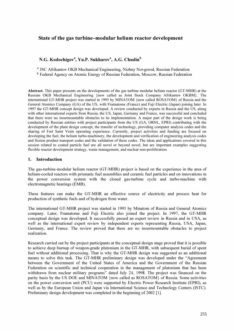
State of the gas turbine–modular helium reactor development
N.G. Kodochigova, Yu.P. Sukhareva, A.G. Chudinb a b
JSC Afrikantov OKB Mechanical Engineering, Nizhny Novgorod, Russian Federation Federal Agency on Atomic Energy of Russian Federation, Moscow, Russian Federation
Abstract. This paper presents on the developments of the gas turbine modular helium reactor (GT-MHR) at the Russian OKB Mechanical Engineering {now called as Joint Stock Company Afrikantov OKBM}. The international GT-MHR project was started in 1995 by MINATOM {now called ROSATOM} of Russia and the General Atomics Company (GA) of the US, with Framatome (France) and Fuji Electric (Japan) joining later. In 1997 the GT-MHR concept design was developed. A review conducted by experts in Russia and the US, along with other international experts from Russia, the US, Japan, Germany and France, was successful and concluded that there were no insurmountable obstacles to its implementation. A major part of the design work is being conducted by Russian entities with project participants from the US (GA, ORNL, EPRI) contributing with the development of the plant design concept, the transfer of technology, providing computer analysis codes and the sharing of Fort Saint Vrain operating experience. Currently, project activities and funding are focused on developing the fuel, the helium turbo-machinery, the development and verification of engineering analysis codes and fission product transport codes and the validation of these codes. The ideas and applications covered in this session related to coated particle fuel are all novel or beyond novel, but are important examples suggesting flexible reactor development strategy, waste management, and nuclear non-proliferation.
1. Introduction The gas-turbine-modular helium reactor (GT-MHR) project is based on the experience in the area of helium-cooled reactors with prismatic fuel assemblies and ceramic fuel particles and on innovations in the power conversion system with the closed gas-turbine cycle and turbo-machine with electromagnetic bearings (EMB). These features can make the GT-MHR an effective source of electricity and process heat for production of synthetic fuels and of hydrogen from water. The international GT-MHR project was started in 1995 by Minatom of Russia and General Atomics company. Later, Framatome and Fuji Electric also joined the project. In 1997, the GT-MHR conceptual design was developed. It successfully passed an expert review in Russia and in USA, as well as the international expert review by independent experts representing Russia, USA, Japan, Germany, and France. The review proved that there are no insurmountable obstacles to project realization. Research carried out by the project participants at the conceptual design stage proved that it is possible to achieve deep burnup of weapon-grade plutonium in the GT-MHR, with subsequent burial of spent fuel without additional processing. That is why the GT-MHR design was suggested as an additional means to solve this task. The GT-MHR preliminary design was developed under the “Agreement between the Government of the United States of America and the Government of the Russian Federation on scientific and technical cooperation in the management of plutonium that has been withdrawn from nuclear military programs” dated July 24, 1998. The project was financed on the parity basis by the US DОЕ and MINATOM {now called as ROSATOM} of Russia. Some activities on the power conversion unit (PCU) were supported by Electric Power Research Institute (EPRI), as well as by the European Union and Japan via International Science and Technology Centers (ISTC). Preliminary design development was completed in the beginning of 2002 [1].
255

The major part of design activities was done by Russian enterprises. Foreign participants of the project (GA, ORNL, EPRI) contributed to the project by developing the plant concept, transferring a number of technologies, computer codes, sharing experience in operation of Fort Saint Vrain reactor, etc. In 2002, the Preliminary design was reviewed by MINATOM and approved as an innovative area in reactor technologies. International cooperation allows employment of the existing experience and reduction of technical risks and design development costs. In Russia, the GT-MHR project is included into the Federal target programme “The energy efficient economics” and into “Russian strategy for the development of nuclear power for the first half of the 21st century” approved by the Government of the Russian Federation as a field of development of new-generation reactor plants assuring high safety and effective generation of electric energy and process heat. The GT-MHR project coordinating committee decided that before final design development starts, all efforts and funds should be concentrated on development work related to fuel, helium turbomachine with EMB, validation of physical codes and fission products transport codes, and their experimental verification. 2. General description of the GT-MHR The GT-MHR project concept is based on modular helium reactors, high-efficiency gas turbines, EMB, high-efficiency compact heat exchangers. The reactor module consists of two interconnected parts: modular high-temperature reactor and PCU with direct closed gas-turbine cycle (Fig. 1). The gas-turbine energy conversion cycle with a helium turbo-machine, recuperator and intermediate cooling assures thermal efficiency at the level of 48%. Altogether, use of direct closed gas-turbine cycle and modular reactor conditions reduction of capital costs for construction, operation, and maintenance owing to simplification of electricity generation cycle and reduction of the number of safety systems. Successful realization of these advantages depends on actual technical solutions.
256
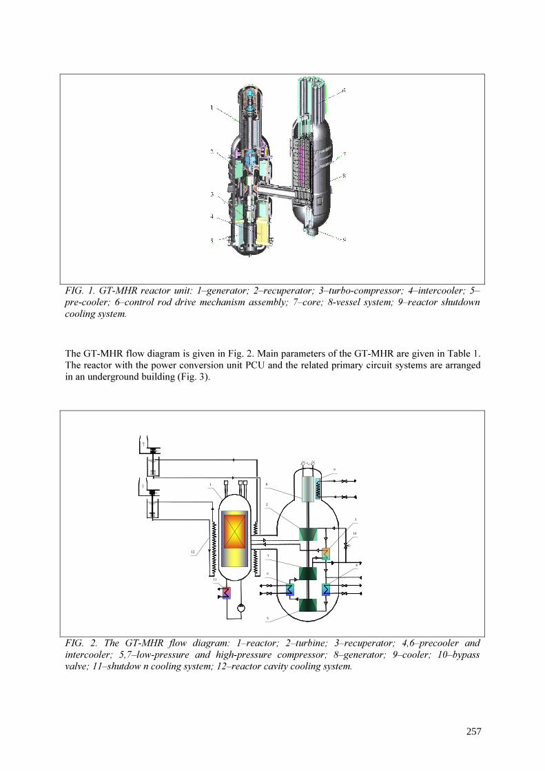
FIG. 1. GT-MHR reactor unit: 1–generator; 2–recuperator; 3–turbo-compressor; 4–intercooler; 5–pre-cooler; 6–control rod drive mechanism assembly; 7–core; 8-vessel system; 9–reactor shutdown cooling system. The GT-MHR flow diagram is given in Fig. 2. Main parameters of the GT-MHR are given in Table 1. The reactor with the power conversion unit PCU and the related primary circuit systems are arranged in an underground building (Fig. 3). FIG. 2. The GT-MHR flow diagram: 1–reactor; 2–turbine; 3–recuperator; 4,6–precooler and intercooler; 5,7–low-pressure and high-pressure compressor; 8–generator; 9–cooler; 10–bypass valve; 11–shutdow n cooling system; 12–reactor cavity cooling system.
4
10
3
9
81
6
5
2
12
11
7
257
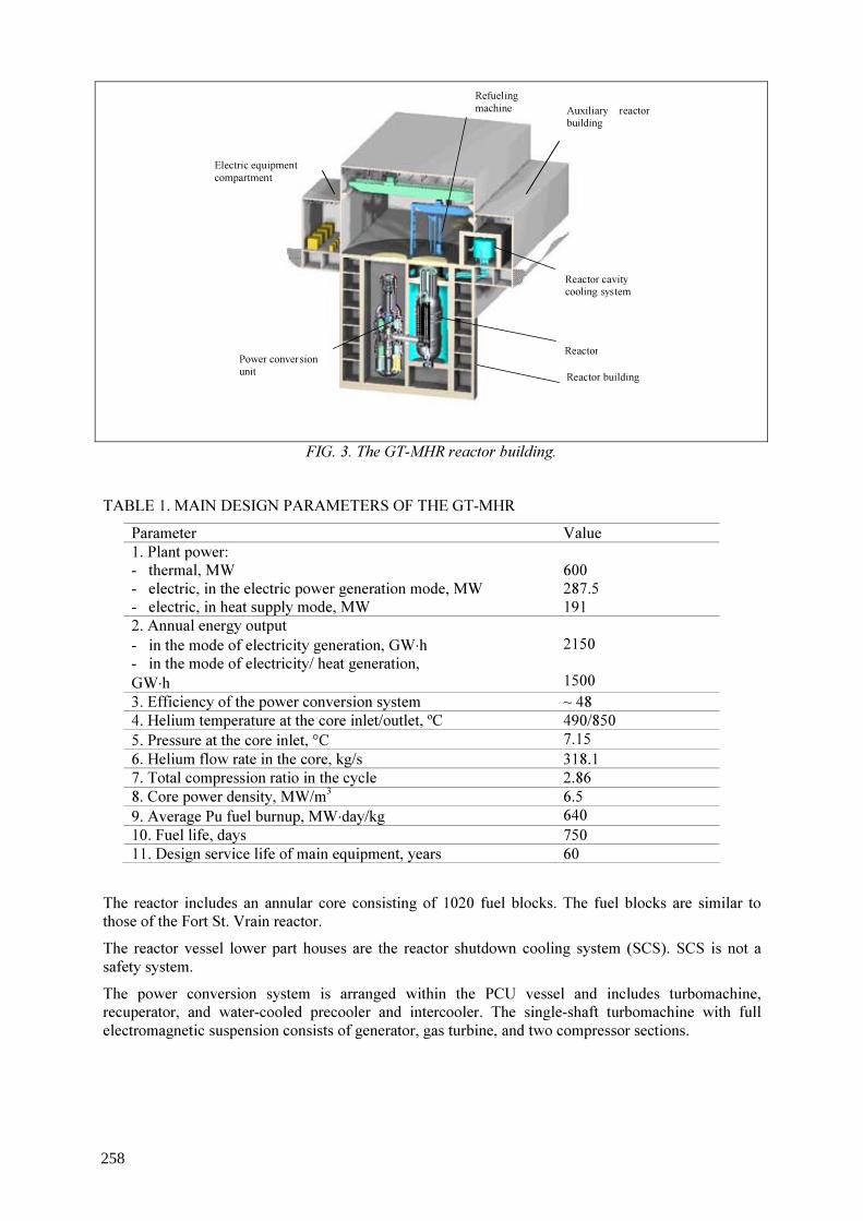
FIG. 3. The GT-MHR reactor building.
TABLE 1. MAIN DESIGN PARAMETERS OF THE GT-MHR
Parameter Value 1. Plant power: - thermal, MW - electric, in the electric power generation mode, MW - electric, in heat supply mode, MW
600 287.5 191
2. Annual energy output - in the mode of electricity generation, GW⋅h - in the mode of electricity/ heat generation, GW⋅h
2150 1500
3. Efficiency of the power conversion system ~ 48 4. Helium temperature at the core inlet/outlet, ºC 490/850 5. Pressure at the core inlet, °C 7.15 6. Helium flow rate in the core, kg/s 318.1 7. Total compression ratio in the cycle 2.86 8. Core power density, MW/m3 6.5 9. Average Pu fuel burnup, MW⋅day/kg 640 10. Fuel life, days 750 11. Design service life of main equipment, years 60
The reactor includes an annular core consisting of 1020 fuel blocks. The fuel blocks are similar to those of the Fort St. Vrain reactor. The reactor vessel lower part houses are the reactor shutdown cooling system (SCS). SCS is not a safety system. The power conversion system is arranged within the PCU vessel and includes turbomachine, recuperator, and water-cooled precooler and intercooler. The single-shaft turbomachine with full electromagnetic suspension consists of generator, gas turbine, and two compressor sections.
Reactor building
Electric equipment compartment
Refueling machine Auxiliary reactor
building
Reactor cavity cooling system
Reactor Power conversion unit
258

The reactor vessel is surrounded by the surface cooler of the passive reactor cavity cooling system (RCCS). RCCS assures removal of heat from the reactor in all accidents, including accidents with full loss of primary helium. 3. Safety Main target of new-generation reactor plants should be guaranteed by prevention of serious accidents with radioactive products release into the environment. It may be achieved only if the reactor meets the inherent safety requirements. In the GT-MHR this target is reached owing to physical characteristics of the core, and to the following technical solution: 1) use of small fuel particles (200 µm in diameter) with multi-layer coating of pyrolytic carbon
and silicon carbide; 2) negative feedback between the core temperature and reactor power, which leads to reactor
self-shutdown in case of emergencies associated with fuel temperature increase; 3) core design characteristics (annular geometry, low specific capacity, large height-over-
diameter ratio), which allows decay heat removal via the reactor vessel surface and further to the ultimate heat sink (atmospheric air) by natural mechanisms: radiation, heat conductivity, and convection; and
4) use of graphite and carbon-carbon composite materials (CCCM) as the core structural materials; together with the passive decay heat removal system, it brings about the concept of a core that does not melt in any accident, including beyond-design-basis ones.
At the preliminary design stage, safety estimations were performed for normal operation and for accidents. The following accidents have the worst radiological consequences: - Control and protection system (CPS) standpipe rupture with heat removal by the passive RCCS
(design-basis accident); and - CPS standpipe rupture plus failure of reactor emergency protection system actuation, with heat
removal by the passive RCCS (beyond-design-basis accident). Main assumptions adopted during analysis of the mentioned accidents: - low-pressure containment (confinement); - controllable release of the coolant via the stack during depressurization; and - directed release of activity via filters with subsequent fuel heating from initial temperatures to
<1600 оC. Population radiation doses during normal operation and in accidents resulting from the estimation are given in Table 2. TABLE 2.
Reactor plant condition Regulatory documentation requirement, mSv/an [2, 3]
Results of analysis, mSv/an
Normal operation ≤ 2.10-2 2.10-5 Design-basis accident with CPS standpipe rupture
≤ 5 on the border of the restricted area
0.4
Beyond-design-basis accident with CPS standpipe rupture and failure of emergency protection system actuation
≤ 5 on the border of protection measures planning area
0.6
The safety estimation results show the following: - allowable level of fuel temperatures (1600 °С) is not exceeded in any accident, including those
with failures of all active means of reactor shutdown and cooling (see Fig. 4);
259

- in case of accidents with the worst radiological consequences, evacuation of the population is not required; and
- even if all heat removal systems, including RCCS, fail to actuate, there is a considerable time margin (not less than 50 hours from the accident beginning) for the personnel to undertake timely measures to prevent fuel temperature increase above the design limit.
Tem
perat
ure, °C
0 50 100 150 200 250 T i m e , h
0
400
800
1200
1600
maximal temperature of compacts average temperature of compacts temperature of vessel
FIG. 4. Temperature state of the core and reactor vessel during depressurization with cooling by RCCS. 4. GT-MHR fuel supply and non-proliferation of fissionable materials Analyses of the GT-MHR core with various fuel types proved the following: 1) capability to vary fuel inventory weight and enrichment; and 2) flexible physical characteristics of the core that has an assigned power density and fixed
geometrical dimensions. This permits to start the reactor with one fuel and then change for another. Comparison of various fuel types in the GT-MHR, which can use various fuel as initial (weapon-grade plutonium, low-enriched (< 20%) uranium, МОХ fuel based on weapon-grade and reactor plutonium diluted with uranium or thorium dioxide), proved that it is possible to use these types of fuel without introducing modifications to the core design (arrangement and number of control and protection system rods, dimensions of the core and reflectors). The analysis showed that from the point of view of fuel cycle economy (fissionable isotope consumption), preference should be given to the core variant with reactor plutonium reprocessed from PWR spent fuel.
260
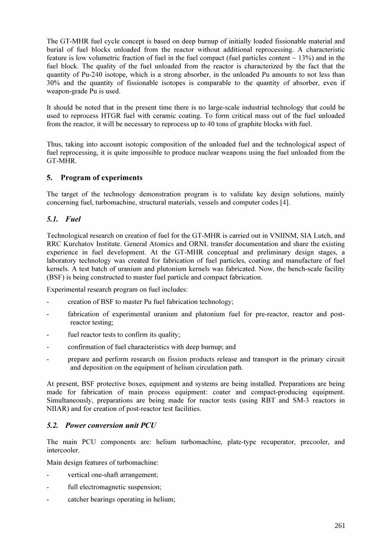
The GT-MHR fuel cycle concept is based on deep burnup of initially loaded fissionable material and burial of fuel blocks unloaded from the reactor without additional reprocessing. A characteristic feature is low volumetric fraction of fuel in the fuel compact (fuel particles content ~ 13%) and in the fuel block. The quality of the fuel unloaded from the reactor is characterized by the fact that the quantity of Pu-240 isotope, which is a strong absorber, in the unloaded Pu amounts to not less than 30% and the quantity of fissionable isotopes is comparable to the quantity of absorber, even if weapon-grade Pu is used. It should be noted that in the present time there is no large-scale industrial technology that could be used to reprocess HTGR fuel with ceramic coating. To form critical mass out of the fuel unloaded from the reactor, it will be necessary to reprocess up to 40 tons of graphite blocks with fuel.
Thus, taking into account isotopic composition of the unloaded fuel and the technological aspect of fuel reprocessing, it is quite impossible to produce nuclear weapons using the fuel unloaded from the GT-MHR. 5. Program of experiments The target of the technology demonstration program is to validate key design solutions, mainly concerning fuel, turbomachine, structural materials, vessels and computer codes [4]. 5.1. Fuel
Technological research on creation of fuel for the GT-MHR is carried out in VNIINM, SIA Lutch, and RRC Kurchatov Institute. General Atomics and ORNL transfer documentation and share the existing experience in fuel development. At the GT-MHR conceptual and preliminary design stages, a laboratory technology was created for fabrication of fuel particles, coating and manufacture of fuel kernels. A test batch of uranium and plutonium kernels was fabricated. Now, the bench-scale facility (BSF) is being constructed to master fuel particle and compact fabrication. Experimental research program on fuel includes: - creation of BSF to master Pu fuel fabrication technology; - fabrication of experimental uranium and plutonium fuel for pre-reactor, reactor and post-
reactor testing; - fuel reactor tests to confirm its quality; - confirmation of fuel characteristics with deep burnup; and - prepare and perform research on fission products release and transport in the primary circuit
and deposition on the equipment of helium circulation path. At present, BSF protective boxes, equipment and systems are being installed. Preparations are being made for fabrication of main process equipment: coater and compact-producing equipment. Simultaneously, preparations are being made for reactor tests (using RBT and SM-3 reactors in NIIAR) and for creation of post-reactor test facilities. 5.2. Power conversion unit PCU
The main PCU components are: helium turbomachine, plate-type recuperator, precooler, and intercooler. Main design features of turbomachine: - vertical one-shaft arrangement; - full electromagnetic suspension; - catcher bearings operating in helium;
261

- helium-cooled generator; and - sliding seals of the turbocompressor stator that limit leaks between cavities with different pressure. The main target of the experimental research program on PCU is experimental validation of operability of the turbocompressor with EMB, of the recuperator, etc., as well as validation of their design characteristics. The following experimental work has been completed by the present moment: - tests of turbocompressor stator seal mockup in air; - studies of the rotor vertical model and EMB model at the “minimockup” test facility, when
passing a resonance frequency; - study of characteristics of EMB with control system; - tests of various EMB sensor types; - fabrication of rotor model scaled 1:3 has been commenced for further tests of various rotor
designs and tests of control system; - membrane coupling model fabrication has been commenced; and - design development of the test facility for full-scale turbocompressor tests is now in progress. The compact high-efficiency plate-type recuperator design was developed within the framework of the GT-MHR project. For support of the recuperator design, experimental studies of the fabrication technology for recuperator heat exchange surface elements with compactness of 1 500 m2/m3 was performed. Besides, a technological mockup of a recuperator element and a full-scale recuperator heat exchange element were fabricated. The recuperator element was subject to comprehensive tests in OKBM at the air and helium test facilities under the operating temperature. 5.3. Materials
Main reactor components use structural materials earlier developed for Russian HTGR designs. Experimental program on structural materials includes:
• technology development and tests of reactor graphite based on pitch coke; mastering of the technology for structural element fabrication of this graphite;
• technology development, fabrication and tests of CCCM to be used for fabrication of absorber rod elements and in-vessel structure elements;
• tests and certification of materials for turbine and reactor; and • tests of the material for the vessel system, mastering of the fabrication technology, material
certification. 6. Possible role of the GT-MHR in nuclear power Possible role of the GT-MHR in nuclear power results from its characteristics, which allow expansion of nuclear power application. These characteristics include: - capability of obtaining coolant temperatures of up to 1000 °C at the core outlet; - high safety that entirely prevents core meltdown without the need for operator actions; - low level of thermal and radiological releases into the environment; and
262

- flexibility of the fuel cycle, use of various fuel types without modifying the reactor design. The above-mentioned characteristics allow GT-MHR application for high-efficiency generation of electric energy in the closed gas-turbine cycle. Waste heat can be used for district heating. High safety of the GT-MHR is achieved owing to fuel properties and design characteristics, not due to increasing the number of safety systems and raising requirements for them. This allows reduction of the amount of equipment, of capital and operation costs, and creation of a competitive nuclear power plant. GT-MHR reactors can generate process heat that can be used for production of hydrogen from water, for production of synthetic liquid fuel from coal, for oil processing, etc. The last mentioned field of application opens new perspectives for nuclear power, which is comparable with electric power in terms of output. 7. Conclusions Design and experimental work completed by the present moment confirm that the project meets all requirements to new-generation reactor plants for full-scale nuclear power: - Reactor technology with the modular helium reactor GT-MHR is characterized by high safety
that prevents fuel meltdown without the need for NPP personnel actions. - The GT-MHR can be successfully applied in nuclear power for generation of electric energy
and for technological purposes, including production of hydrogen from water. - Minimal amount of equipment and systems conditions reduction of capital and operation costs
and low cost of generated electric energy. - The GT-MHR is a good example of international cooperation in the field on innovative nuclear
technology development.
REFERENCES [1] KODOCHIGOV, N.G., SUKHAREV, Yu.P., FOMICHENKO, P.A., CHUDIN, A.G.,
“State of HTGR developments in Russia”, Proc. of Technical Working Group Meeting on Gas Cooled Reactors. (TWG-GCR-18). Istanbul, Turkey, 16-18 June 2003, http://www.iaea.org/inisnkm/index.html
[2] SP-AS-99, SP2.6.1.27-2000 “Sanitary rules for NPP design and operation”, http://www.rosenergoatom.ru/eng/safety-and-ecology/nuclear-and-radiation/radiation-safety/
[3] NRB-99, SP2.6.1.758-99, “Radiological safety norms”, Strengthening U.S-Russian Cooperation on Nuclear Non-proliferation, The National Academies Press, Washington, D.C.
[4] Documents of the International Coordination Committee on the GT-MHR Project, May 5-9, 2003, San-Diego, USA (unpublished)
263
LIST OF PARTICIPANTS
Afanasyev, A.A. †
Ministry of Fuel and Energy of Ukraine, State Department on Nuclear Energy, Ulitsa Kreshchatik 30-34, 01601 Kiev, Ukraine
Atger, A. Department of Technical Cooperation,
International Atomic Energy Agency, Wagramer Strasse 5, 1040 Vienna, Austria
Bakker, K. Nuclear Research& Consultancy Group (NRG),
P.O. Box 25
1755 ZG Petten, The Netherlands
Broecker, P. Anton-Storch-Str. 4, 63457 Hanau, Germany [email protected]
Chernikov, A. SIA-Lutch, 24, Zheleznodorozhnaya st., 142100 Podolsk, Moscow Region, Russian Federation [email protected]
Chunhe, T. Institute of Nuclear and New Energy Technology, Tsinghua University, 100084 Beijing, China [email protected]
Colak, U. Hacettepe University, Nuclear Engineering Department, Beytepe, 06532 Ankara, Turkey [email protected]
Ebert, E. Framatome ANP GsmbH, Freyeslebenstrasse 1, 91058 Erlangen, Germany [email protected]
Feltus, M.A. Office of Nuclear Energy, Science and Technology, U.S. Department of Energy, Room-A-238, 19901 Germantown Road, 20874 Germantown, MD, U.S.A. [email protected]
___________________________________________________________________________
† Deceased.

Froschauer, K. RWE NUKEM,
Industriestr. 13, 63754 Alzenau, Germany [email protected]
Fukuda, K. Japan Atomic Energy Research Institute (JAERI),
2-chome 27-1-610, Kitayamada, Tsuzuki-ku,
Yokohama, Kanagawa-Prefecture, 224-0021, Japan
Furrer, G. APAT,
Via Vitaliano Branceti, 48,
00144 Rome, Italy
Guillermier, P. AREVA NP, Fuel Sector,
10, rue Juliette Recamier,
69456 Lyon Cedex 06, France
Gulol, O.O. Turkish Atomic Energy Authority,
Department of Nuclear Safety Eskisehir,
Yolu 9.km 8.kat,
06530 Lodumlu Ankara, Turkey
Gurin, V. National Science Centre -Kharkov Institute of Physics & Technology 1. Akademicheskaya Str., 61108 Kharkov, Ukraine
Hoffelner, W. PSI, 5232 Villigen, Switzerland [email protected]
Kadiroglu, O.K. MESA KORU SITESI,
Manolya Blok 69,
Cayyolu 06810 Ankara, Turkey
Karnaukhov, I. National Science Centre -Kharkov Institute of
Physics & Technology, 1. Akademicheskaya Str., 61108 Kharkov, Ukraine
Karrasch, B. Framatome ANP GmbH, Freyeslebenstrasse 1, 91058 Erlangen, Germany
Klepikov, V. National Science Centre -Kharkov Institute of Physics & Technology, 1. Akademicheskaya Str., 61108 Kharkov, Ukraine

Krasnorutskiy, V. National Science Centre -Kharkov Institute of Physics & Technology, 1. Akademicheskaya Str., 61108 Kharkov, Ukraine
Lee, J.W.
Korea Atomic Energy Research Institute, P.O.Box 105, Yuseong, Daejeon, Republic of Korea [email protected]
Lee, Y.W. Korea Atomic Energy Research Institute, P.O.Box 105, Yuseong, Daejeon, Republic of Korea [email protected]
Makihara, Y. Department of Nuclear Safety and Security,
International Atomic Energy Agency,
Wagramer Strasse 5, 1040 Vienna, Austria
Marsh, G. Nexia Solutions Ltd.,
Springfields, Salwick,
Advanced Reactors and Materials,
PRESTON, Lancs., United Kingdom [email protected]
Martin, D. Nuclear fuel consultant,
63 Foliat Drive, Wantage Oxon OX12 7AL, United Kingdom
Methnani, M. Department of Nuclear Energy,
International Atomic Energy Agency,
Wagramer Strasse 5, 1040 Vienna, Austria
Mykhaylov, V. National Science Centre ”Kharkov Institute of
Physics & Technology”, 1. Akademicheskaya Str., 61108 Kharkov, Ukraine
Nabielek, H. Research Center Jülich Fuel Cells Project , 52425 Jülich, Germany [email protected]
Nawada, H.P. Department of Nuclear Energy, International Atomic Energy Agency,
Wagramer Strasse 5, 1040 Vienna, Austria
Neklyudov, I. The National Academy of Sciences of Ukraine,
54 Volodymyrska St.,
01601, Kiev-30, Ukraine
Odeychuk, M. National Science Centre -Kharkov Institute of Physics & Technology,

1. Akademicheskaya Str., 61108 Kharkov, Ukraine [email protected]
Okubo, K. Nuclear Fuel Industries, Ltd., 3135-41, Muramatsu, Tokai-mura, Naka-gun, 319-1196 Ibaraki, Japan [email protected]
Phelip, M. CEA Cadarache,
13108 Saint Paul lez Durance, France
Pouchon, M. PSI, 5232 Villigen, Switzerland [email protected]
Rubin, S. United States Nuclear Regulatory Commission
(USNRC), 11545,
20852-2788 Rockville, MD, U.S.A.
Sawa, K. JAEA,
Oarai Research establishment,
3607 Niibori, Narit-cho, Oarai-machi,
Higashiibaraki-gun, Ibaraki, 319-1394, Japan
Sukharev OKB Mechanical Engineering
Burnakovsky Proezd, 15 603074 Nizhny Novgorod, Russian Federation [email protected]
Suwardi PPTBDU-BATAN, Puspiptek 5F3, Serpong, 15310 Tangerang, Indonesia [email protected]
Takahashi, M. Nuclear Fuel Industries, The Japan Atomic Power Co.(JAPC), Mitoshiro Bld. 1-1, Knada-Mitoshiro-cho, Chiyoda-ku, 101-0053 Tokyo, Japan [email protected]
Talamo, A. Nuclear and Reactor Physics Department-Royal Institute
of Technology, Albanova University Center,
Roslagstullsbacken 21,
106 91 Stockholm, Sweden
Toscano, E. European Commission, Joint Research Centre,
Institute for Transuranium Elements, Postfach 2340, 76125 Karlsruhe, Germany

Tsuchie, Y. The Japan Atomic Power Co. (JAPC),
Mitoshiro Bld. 1-1, Knada-Mitoshiro-cho,
Chiyoda-ku, 101-0053 Tokyo, Japan
Ueta, S. Japan Atomic Energy Agency (JAEA), JAERI
Nuclear Science and Energy Directorate
3607 Niibori, Narita-cho, Oarai-mati,
Higashiibaraki-gun, Ibaraki, 311-1394, Japan
Vaidya, V.N. Bhabha Atomic Research Centre,
Trombay 4000 085 Mumbai, India
Venter, S. NECSA Nuclear Fuel Cycle – Building C5 PO BOX 582 Pretoria 0001, South Africa [email protected]
Verfondern, K. Research Center Jülich Institute for Safety Research
and Reactor Technology,
52425 Julich, Germany
Volobuev, O. National Science Centre -Kharkov Institute of
Physics & Technology, 1. Akademicheskaya Str. 61108 Kharkov, Ukraine
Voyevodin, V. National Science Centre -Kharkov Institute of Physics & Technology 1. Akademicheskaya Str. 61108 Kharkov, Ukraine
Werner, H. Institute for Safety Research and Reactor Technology,
52425 Julich, Germany
Yakovlev, V. National Science Centre -Kharkov Institute of Physics & Technology, 1. Akademicheskaya Str. 61108 Kharkov, Ukraine
Zelenskiy, V. National Science Centre -Kharkov Institute of Physics & Technology, 1. Akademicheskaya Str. 61108 Kharkov, Ukraine


