Status of KVN Instrumental Phase Calibration System Development Do-Heung Je 1 , Moon-Hee Chung 1 , Ji-Man Kang 1 , Seung-Rae Kim 1 , Min-Kyu Song 1 , Sung-Mo Lee 1 , Taehyun Jung 1 , Seog-Tae Han 1 , Do-Young Byun 1 , Seog-Oh Wi 1 , Bong-Won Son 1 , Soo-Yeon Kim 2 , and Won-Kyu Lee 3 1 Korea Astronomy and Space Science Institute 2 Korea University 3 Korea Research Institute of Standards and Science 2013. Oct. 12. 2 nd IVTW
Transcript
Status of KVN Instrumental Phase Calibration System Development
Byun1, Seog-Oh Wi1, Bong-Won Son1, Soo-Yeon Kim2, and Won-Kyu Lee3
1Korea Astronomy and Space Science Institute2Korea University
3Korea Research Institute of Standards and Science
2013. Oct. 12.2nd IVTW
Contents• KVN Round Trip System
– Specification– Development progress– System configuration– Test results (old & new)
• KVN Wide-band phase calibration– Specification : power vs freq, reference frequency – P-cal System Configuration – Component’s design and fabrication– Timeline
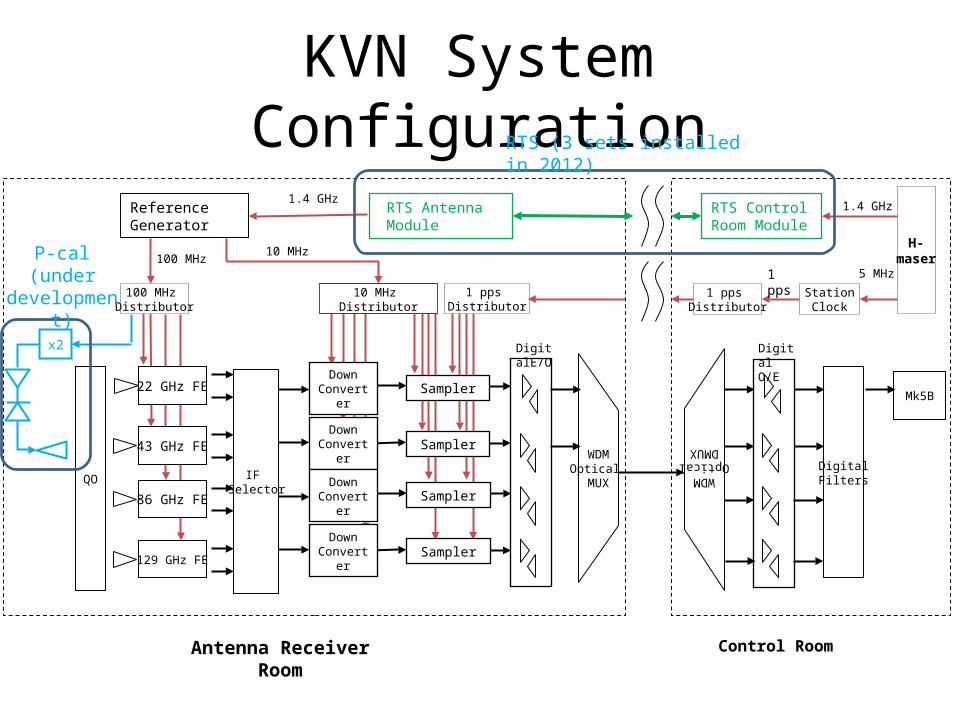
KVN System Configuration
H-maser
Antenna Receiver Room
43 GHz FE
22 GHz FE
1 pps Distributor
100 MHz Distributor
10 MHz Distributor
1 pps Distributor
5 MHz
1.4 GHz
Control Room
WDMOptical
MUX
Digi-talE/O
Down Con-
verter
Down Con-
verter
Sampler
SamplerWDM
OpticalDMUX
Digital O/E
DigitalFilters
Mk5B
IF Selector
StationClock
1 pps
ReferenceGenerator
RTS Antenna Module
RTS Control Room Module
1.4 GHz
10 MHz100 MHz
Down Con-
verter
Down Con-
verter
Sampler
Sampler
86 GHz FE
129 GHz FE
QO
x2
P-cal(under de-velopment)
RTS (3 sets installed in 2012)
KVN RTS(Round Trip System) Speci-fication
• RTS is needed for compensating the cable length change due to temperature variations & move-ment
• KASI developed KVN RTS through research coop-eration with KRISS (Korea Research Institute of Standards and Science) in 2011.
• KASI installed RTS system in 3 KVN sites in 2012. • Fiber-optic reference signal transmission method
(from NICT, Dr. Fujieda, 2009)• The measured stability satisfied the stability spec-
ification, 2E-16@1,000s.• Real-time remote signal monitoring function
was added.
KVN RTS Configuration ,
,
,
.
Remote signal phase cannot be measured directly. We need any method to check remote signal phase for diagnosis of the system performance.
Expectation of remote signal phase
𝜑𝑣𝑐𝑜+𝜑 𝑓𝑖𝑏𝑒𝑟=𝜑𝑟𝑒𝑚𝑜𝑡𝑒
.
() ,
.
𝜑𝑣𝑐𝑜=𝜑𝑟𝑒𝑚𝑜𝑡𝑒−𝜑 𝑓𝑖𝑏𝑒𝑟
Remote signal phase can be expected from vco signal phase and round-trip signal phase.
laser
VCO
MZM
Photo Diode
H-maser
𝑉 𝑣𝑐𝑜
Phase Compensation Circuit
𝑉 𝑟𝑡
𝑉 𝑟𝑒𝑓
𝑉 𝑐
Observation Building
Antenna Vertex Room
laser MZM
Photo Diode
𝑉 𝑟𝑒𝑚𝑜𝑡𝑒
Vector Voltmeter
𝑉 𝑟𝑒𝑓
𝑉 𝑣𝑐𝑜
𝑉 𝑟𝑡
Controller
KVN RTS Test setup
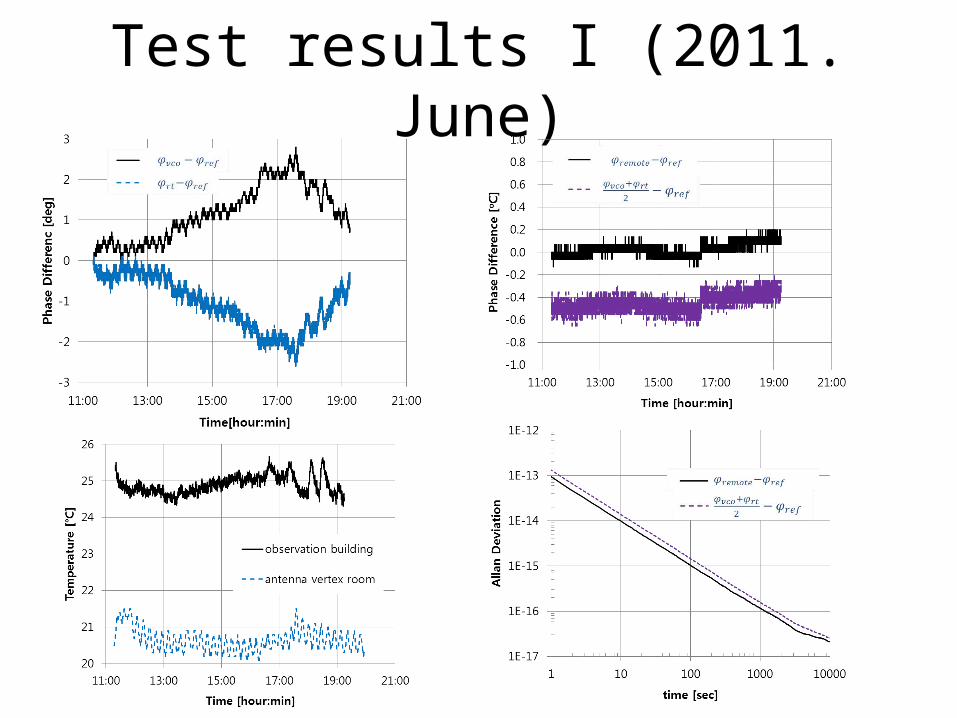
Test results I (2011. June)
Test results II (2012. Jan.)
Test results III (after temperature stabilization)
Test results IV (after temperature stabilization)
Comparison of Allan deviations before and after temperature stabilization
After stabiliza-tion
Before stabi-lization
Contents• Round Trip System
– Specification– Development progress– System configuration– Test results (old & new)
• Wide-band phase calibration– Specification : power vs freq, reference frequency – System Configuration – Component’s design and fabrication– Timeline
KVN 4 ch Receiver (Front End)
45 degree mirror
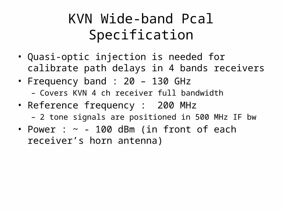
KVN Wide-band Pcal Specification
• Quasi-optic injection is needed for calibrate path delays in 4 bands receivers
• Frequency band : 20 – 130 GHz– Covers KVN 4 ch receiver full bandwidth
• Reference frequency : 200 MHz– 2 tone signals are positioned in 500 MHz IF bw
• Power : ~ - 100 dBm (in front of each receiver’s horn antenna)
KVN P-cal Configuration
Refer-ence
Genera-tor
Feeder
Comb Genera-
tor
100 MHz
200 MHz
20-130 GHz
Attenua-tor
Quasi-Optic Injection
Double-ridged feed-horn
doubler Power Amp
< 50 GHz
Quasi Optic Injection
• KVN is comprised of 3 LPF, several mirrors. • Quasi optic P-cal injection is needed.• Double ridged feedhorn, ellipsoidal mirror, Mylar
Wideband Feed Horn Development (Dr. Moon-Hee Chung)
• Double-ridged waveguide horn was designed and fabricated as a ul-tra-wide band feeder
• VSWR : < 2 @ 20-130 GHz • Aperture size : 24 mm x 28 mm• Lower return loss measured above 80 GHz
Timeline for KVN wideband P-cal
• P-cal system using commercial comb generator(< 50 GHz or 86 GHz), wideband feeder, Quasi-optic injection system– 1st injection test : 2013. Dec.– 2nd injection test : 2013. March.– 3 sets installation : 2014. July (TBD)
• Further Works for full-band Phase calibration – NLTL MMIC Chip development needed.– MMIC Module loaded feeder development.
Summary
• KVN RTS development – 2E-16 @ 1000s – O(E-17) @ 1000s (after temperature stabilization) – Real time remote signal phase expectation method
was suggested.
• KVN wide-band Pcal system is under develop-ment – Ultra wide-band feed is developed. – Quasi-optic injection – Custom designed high frequency comb generator is