Page 1 Status of Landsat 5, Landsat 7, and the Landsat Data Continuity Mission Jim Irons Landsat Data Continuity Mission (LDCM) Project Scientist Laboratory for Atmospheres NASA Goddard Space Flight Center LDCM SRR/MDR/PNAR 22-24 April 2008 Spring Land Cover / Land Use Change Science Team Meeting April 22, 2010 Bethesda, Maryland
Transcript
Page 1
Status of Landsat 5, Landsat 7, and the Landsat Data Continuity Mission
Jim IronsLandsat Data Continuity Mission (LDCM) Project Scientist
Laboratory for AtmospheresNASA Goddard Space Flight Center
LDCM SRR/MDR/PNAR 22-24 April 2008
Spring Land Cover / Land Use Change Science Team Meeting
April 22, 2010Bethesda, Maryland
Page 2
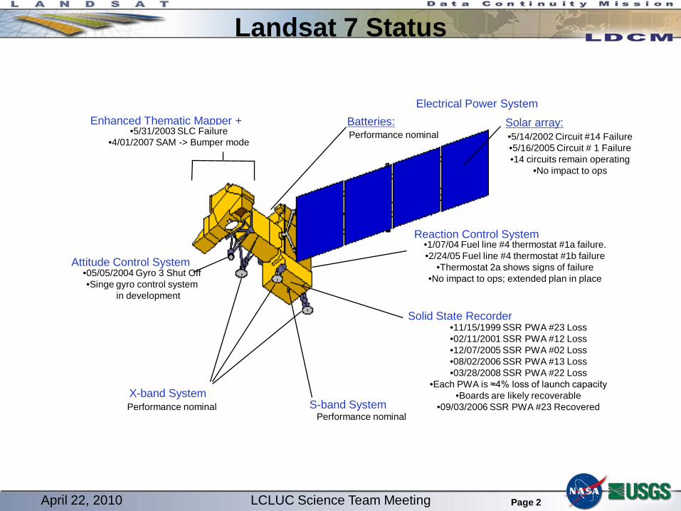
Landsat 7 Status
Attitude Control System
X-band SystemS-band System
Performance nominal
Enhanced Thematic Mapper +•5/31/2003 SLC Failure
•4/01/2007 SAM -> Bumper mode
Electrical Power SystemBatteries:Performance nominal
Solid State Recorder
Reaction Control System•1/07/04 Fuel line #4 thermostat #1a failure.•2/24/05 Fuel line #4 thermostat #1b failure
•Thermostat 2a shows signs of failure•No impact to ops; extended plan in place
•11/15/1999 SSR PWA #23 Loss•02/11/2001 SSR PWA #12 Loss•12/07/2005 SSR PWA #02 Loss•08/02/2006 SSR PWA #13 Loss•03/28/2008 SSR PWA #22 Loss
•Each PWA is ≈4% loss of launch capacity•Boards are likely recoverable
•09/03/2006 SSR PWA #23 RecoveredPerformance nominal
•05/05/2004 Gyro 3 Shut Off •Singe gyro control system
in development
•5/31/2003 SLC Failure
April 22, 2010 LCLUC Science Team Meeting
Page 3
Landsat 7 Status
Landsat 7 - 6 years beyond design life 1999 Launch Spacecraft
– Gyro 3 Failure (Shut down May 5, 2004)• Working additional improvements for software gyro
– Other Spacecraft Issues (non-critical)• Solid State Recorder – 4 memory boards • Electrical Power Subsystem – shunt #14 and shunt #6• Fuel Line Thermostat
ETM+– Scan Line Corrector Failure (May 31, 2003)– Bumper Mode Operations (April 1, 2007)– Collecting over 300 scenes per day
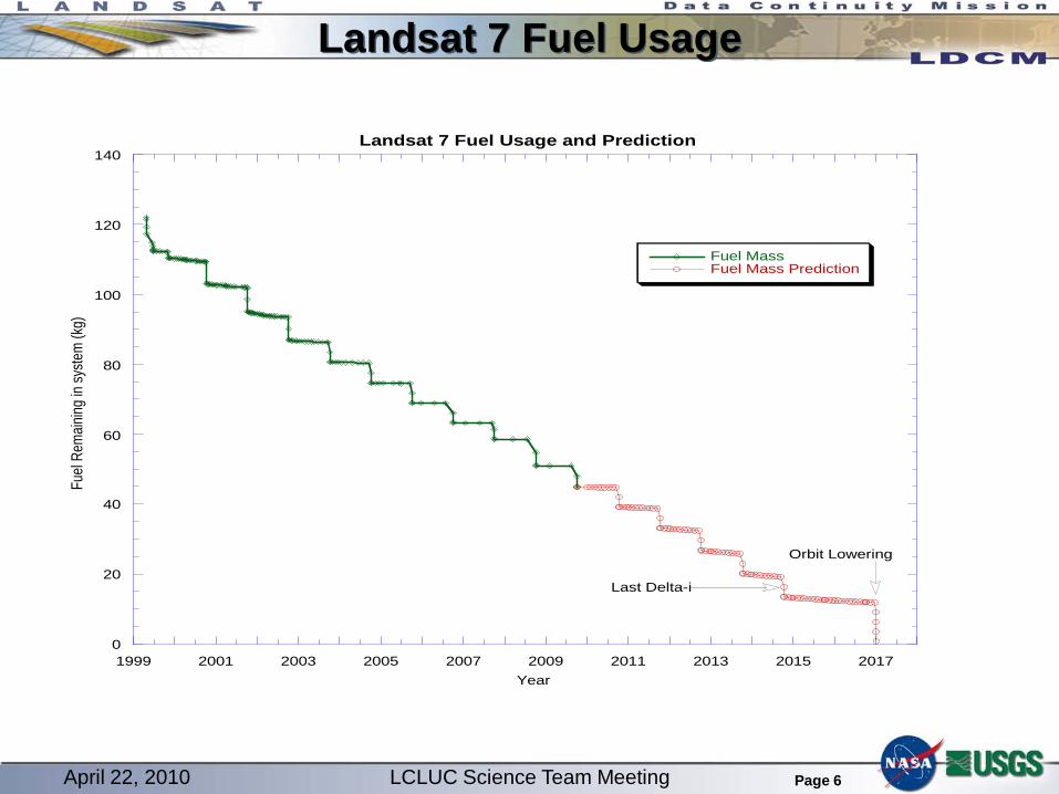
Fuel– Current estimate indicates fuel sufficient for
operations out to 2017
April 22, 2010 LCLUC Science Team Meeting
Page 4
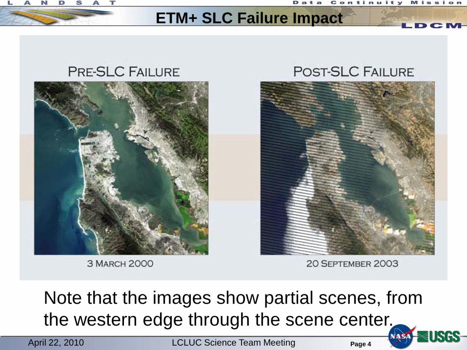
ETM+ SLC Failure Impact
Note that the images show partial scenes, from the western edge through the scene center.
April 22, 2010 LCLUC Science Team Meeting
Page 5
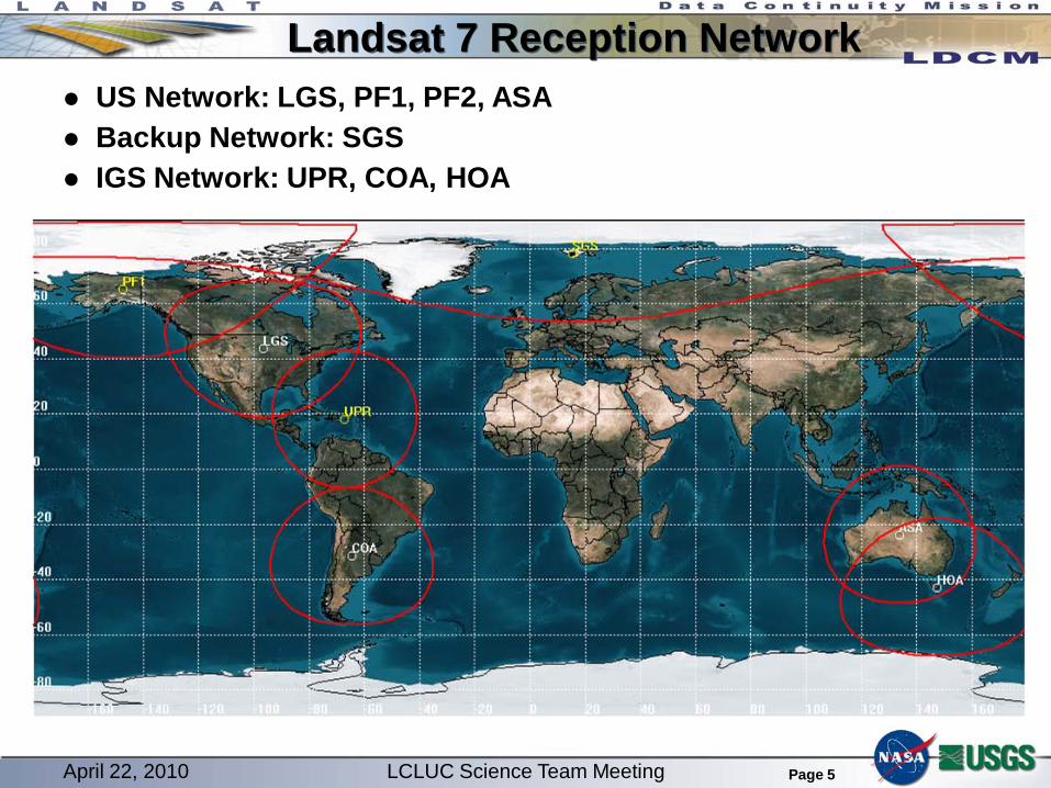
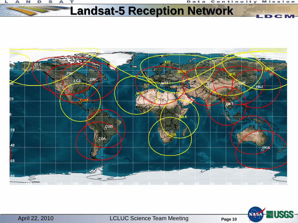
Landsat 7 Reception Network US Network: LGS, PF1, PF2, ASA Backup Network: SGS IGS Network: UPR, COA, HOA
April 22, 2010 LCLUC Science Team Meeting
Page 6
Landsat 7 Fuel Usage
0
20
40
60
80
100
120
140
1999 2001 2003 2005 2007 2009 2011 2013 2015 2017
Landsat 7 Fuel Usage and Prediction
Fuel MassFuel Mass Prediction
Fuel
Rem
aining
in sy
stem
(kg)
Year
Last Delta-i
Orbit Lowering
April 22, 2010 LCLUC Science Team Meeting
Page 7
Landsat 5 Status
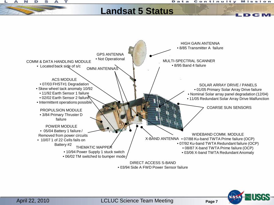
HIGH GAIN ANTENNA• 8/85 Transmitter A failure
MULTI-SPECTRAL SCANNER• 8/95 Band 4 failure
SOLAR ARRAY DRIVE / PANELS• 01/05 Primary Solar Array Drive failure
• Nominal Solar array panel degradation (12/04)• 11/05 Redundant Solar Array Drive Malfunction
DIRECT ACCESS S-BAND• 03/94 Side A FWD Power Sensor failure
COMM & DATA HANDLING MODULE• Located back side of s/c
April 22, 2010 LCLUC Science Team Meeting
Page 8
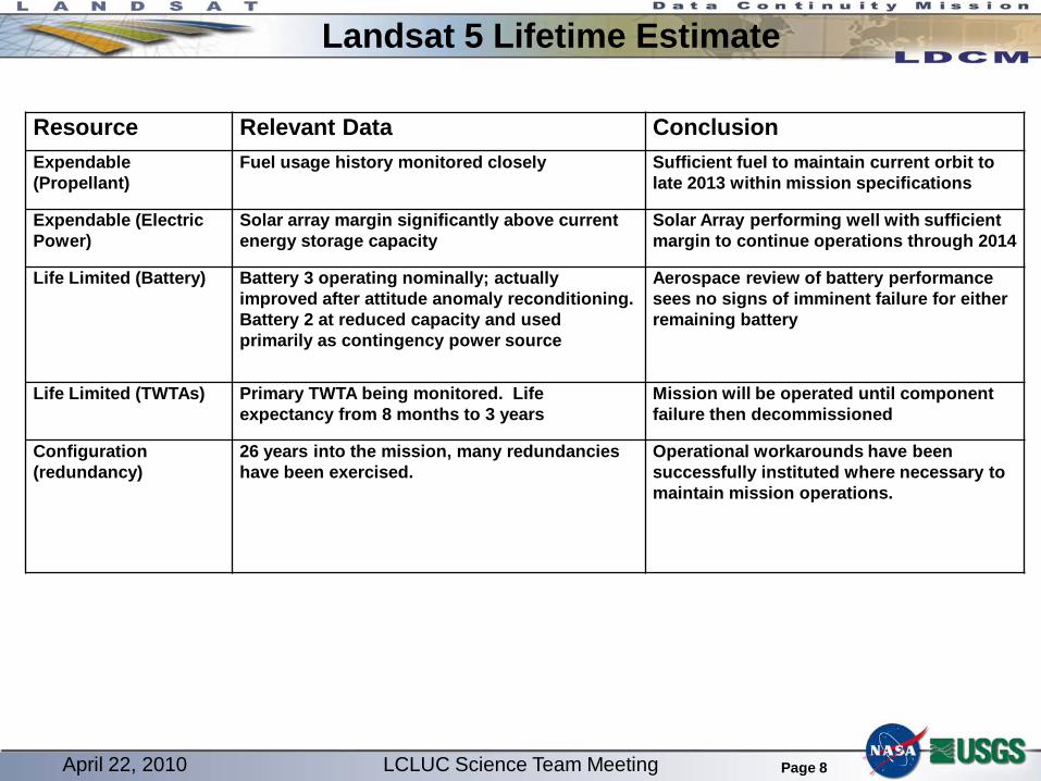
Resource Relevant Data ConclusionExpendable (Propellant)
Fuel usage history monitored closely Sufficient fuel to maintain current orbit to late 2013 within mission specifications
Expendable (Electric Power)
Solar array margin significantly above current energy storage capacity
Solar Array performing well with sufficient margin to continue operations through 2014
Life Limited (Battery) Battery 3 operating nominally; actually improved after attitude anomaly reconditioning. Battery 2 at reduced capacity and used primarily as contingency power source
Aerospace review of battery performance sees no signs of imminent failure for either remaining battery
Life Limited (TWTAs) Primary TWTA being monitored. Life expectancy from 8 months to 3 years
Mission will be operated until component failure then decommissioned
Configuration (redundancy)
26 years into the mission, many redundancies have been exercised.
Operational workarounds have been successfully instituted where necessary to maintain mission operations.
Landsat 5 Lifetime Estimate
April 22, 2010 LCLUC Science Team Meeting
Page 9
Landsat 5 Status
Landsat 5 - 23 years beyond design life 1984 Launch Spacecraft
– Battery 2 Anomaly (On-going) – Oct 2007 – Star Tracker Issue – June 2007– Solar Array Drive
• Fixed array operations – Aug 2006– Current Travelling Wave Tube Amplifier (TWTA)
problems
TM– Functioning normally in bumper-mode– Collecting about 190 scenes per day
Fuel– Current estimates indicate fuel sufficient to
maintain operations through 2013
April 22, 2010 LCLUC Science Team Meeting
Page 10
Landsat-5 Reception Network
April 22, 2010 LCLUC Science Team Meeting
Page 11
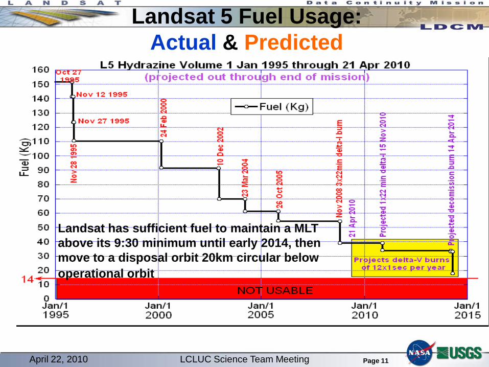
Landsat 5 Fuel Usage: Actual & Predicted
Fall 2006 Delta-i
Maneuvers
Fall 2004 Delta-i
Maneuvers
Spring 2007 Delta-i
Maneuvers
Spring 2009 Delta-i
ManeuversAnnual Delta-i Maneuvers
Spring 2017 Delta-i
Maneuvers
Definitive Fuel Use Predicted Fuel UseAscent
Maneuvers
Landsat has sufficient fuel to maintain a MLT above its 9:30 minimum until early 2014, then move to a disposal orbit 20km circular below operational orbit
April 22, 2010 LCLUC Science Team Meeting
Page 12
Landsat 5 TWTA Status Transverse Wave Tube Amplifier (TWTA) necessary to transmit
TM data through Landsat 5 X-band antenna Landsat 5 carries two TWTA’s, a primary and a redundant
TWTA Failures Primary X-band TWTA Failed – October 1987 Redundant TWTA Failed – December 2009 Primary TWTA Recovered – January 2010
Primary TWTA began to degrade soon after 2010 recovery Helix current is diagnostic of remaining life Current increase trended towards failure in three to eight months
TM duty cycle reduced to 50% to extend TWTA life Current increase began to plateau Resulting trend indicates TWTA lifetime could extend out to three years USGS accepted Science Team priorities for TM data collection
April 22, 2010 LCLUC Science Team Meeting
Page 13
Landsat 5 / A-Train Conjunctions
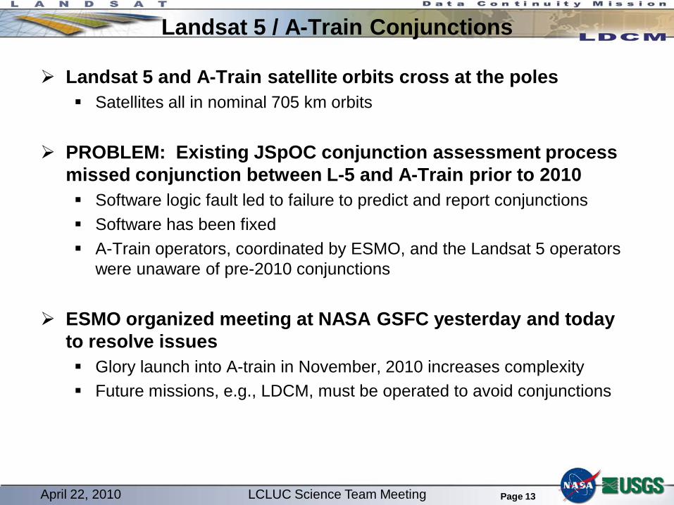
Landsat 5 and A-Train satellite orbits cross at the poles Satellites all in nominal 705 km orbits
PROBLEM: Existing JSpOC conjunction assessment process missed conjunction between L-5 and A-Train prior to 2010 Software logic fault led to failure to predict and report conjunctions Software has been fixed A-Train operators, coordinated by ESMO, and the Landsat 5 operators
were unaware of pre-2010 conjunctions
ESMO organized meeting at NASA GSFC yesterday and today to resolve issues Glory launch into A-train in November, 2010 increases complexity Future missions, e.g., LDCM, must be operated to avoid conjunctions
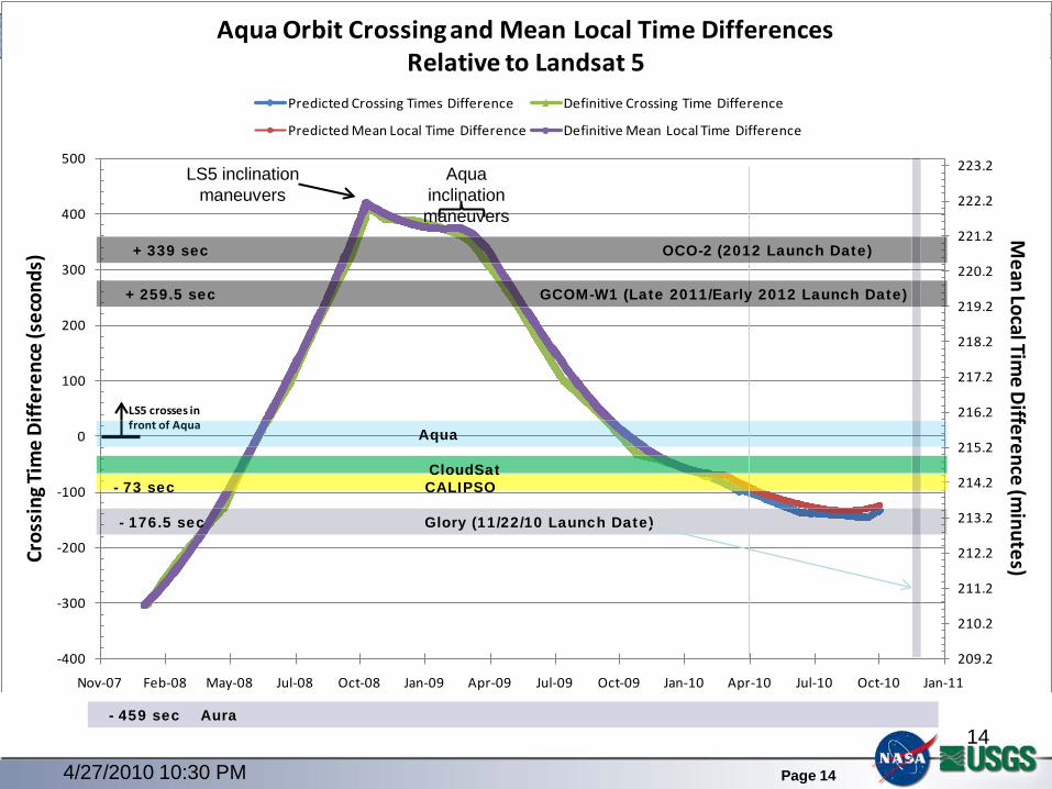
)Aqua Orbit Crossing and Mean Local Time Differences
Relative to Landsat 5Predicted Crossing Times Difference Definitive Crossing Time Difference
Predicted Mean Local Time Difference Definitive Mean Local Time Difference
LS5 crosses in front of Aqua
- 176.5 sec Glory (11/22/10 Launch Date)
Aqua
Aura
CALIPSOCloudSat
- 73 sec
GCOM-W1 (Late 2011/Early 2012 Launch Date)
OCO-2 (2012 Launch Date)
- 459 sec
+ 259.5 sec
+ 339 sec
4/27/2010 10:30 PM
14
LS5 inclination maneuvers
Aqua inclination maneuvers
Page 15
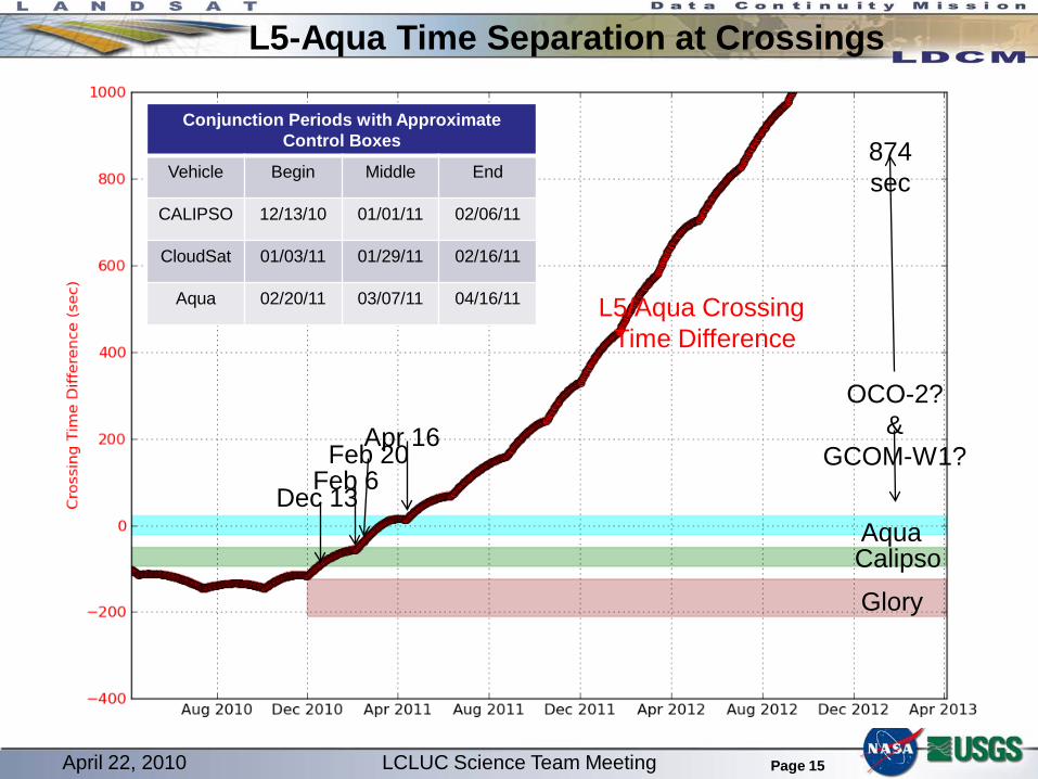
L5-Aqua Time Separation at Crossings
AquaCalipso
Glory
L5/Aqua Crossing Time Difference
OCO-2?&
GCOM-W1?
874 sec
Dec 13Feb 6
Feb 20Apr 16
Conjunction Periods with Approximate Control Boxes
Vehicle Begin Middle End
CALIPSO 12/13/10 01/01/11 02/06/11
CloudSat 01/03/11 01/29/11 02/16/11
Aqua 02/20/11 03/07/11 04/16/11
April 22, 2010 LCLUC Science Team Meeting
Page 16
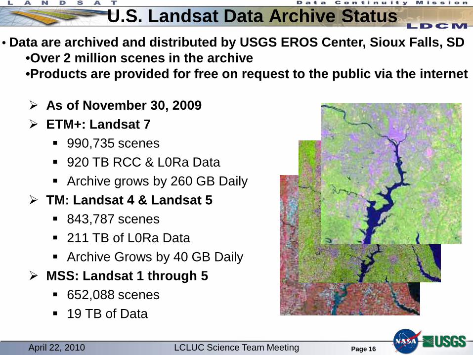
U.S. Landsat Data Archive Status
As of November 30, 2009 ETM+: Landsat 7
990,735 scenes 920 TB RCC & L0Ra Data Archive grows by 260 GB Daily
TM: Landsat 4 & Landsat 5 843,787 scenes 211 TB of L0Ra Data Archive Grows by 40 GB Daily
MSS: Landsat 1 through 5 652,088 scenes 19 TB of Data
• Data are archived and distributed by USGS EROS Center, Sioux Falls, SD•Over 2 million scenes in the archive•Products are provided for free on request to the public via the internet
April 22, 2010 LCLUC Science Team Meeting
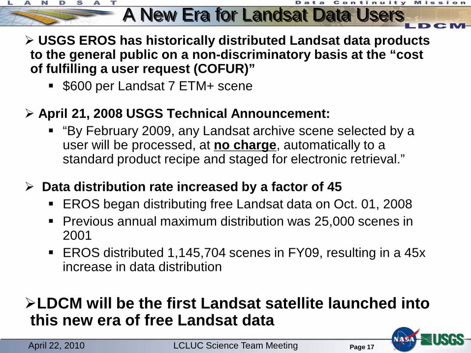
Page 17
A New Era for Landsat Data Users USGS EROS has historically distributed Landsat data products to the general public on a non-discriminatory basis at the “cost of fulfilling a user request (COFUR)” $600 per Landsat 7 ETM+ scene
April 21, 2008 USGS Technical Announcement: “By February 2009, any Landsat archive scene selected by a
user will be processed, at no charge, automatically to a standard product recipe and staged for electronic retrieval.”
Data distribution rate increased by a factor of 45 EROS began distributing free Landsat data on Oct. 01, 2008 Previous annual maximum distribution was 25,000 scenes in
2001 EROS distributed 1,145,704 scenes in FY09, resulting in a 45x
increase in data distribution
LDCM will be the first Landsat satellite launched into this new era of free Landsat dataApril 22, 2010 LCLUC Science Team Meeting
Page 18
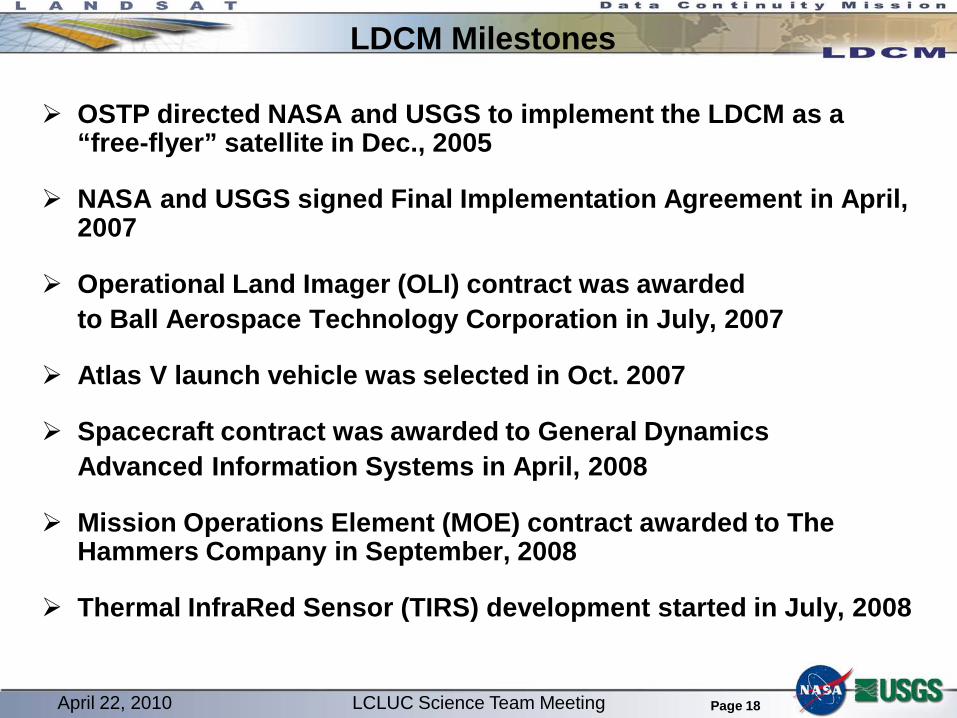
LDCM Milestones
OSTP directed NASA and USGS to implement the LDCM as a “free-flyer” satellite in Dec., 2005
NASA and USGS signed Final Implementation Agreement in April, 2007
Operational Land Imager (OLI) contract was awarded to Ball Aerospace Technology Corporation in July, 2007
Atlas V launch vehicle was selected in Oct. 2007
Spacecraft contract was awarded to General Dynamics Advanced Information Systems in April, 2008
Mission Operations Element (MOE) contract awarded to The Hammers Company in September, 2008
Thermal InfraRed Sensor (TIRS) development started in July, 2008
April 22, 2010 LCLUC Science Team Meeting
Page 19
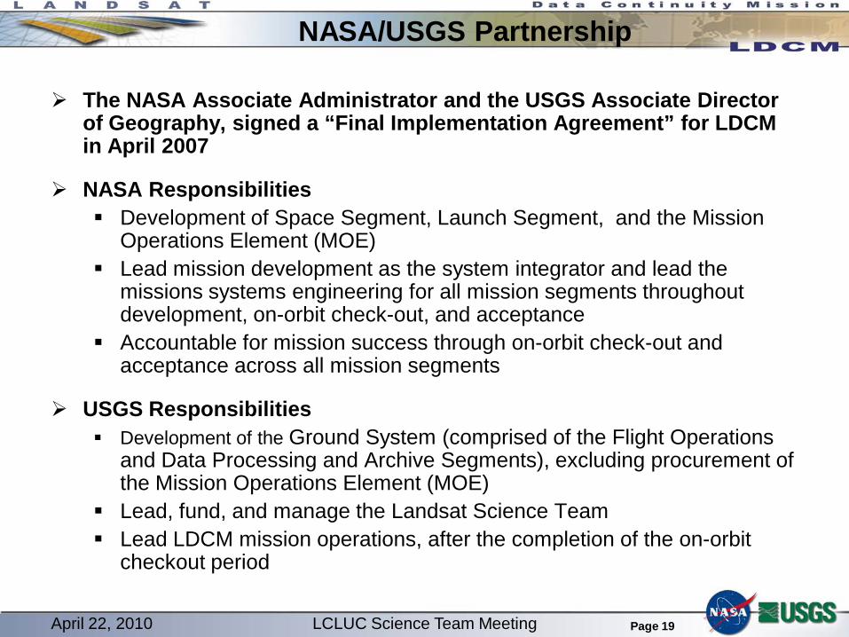
NASA/USGS Partnership
The NASA Associate Administrator and the USGS Associate Director of Geography, signed a “Final Implementation Agreement” for LDCM in April 2007
NASA Responsibilities Development of Space Segment, Launch Segment, and the Mission
Operations Element (MOE) Lead mission development as the system integrator and lead the
missions systems engineering for all mission segments throughout development, on-orbit check-out, and acceptance
Accountable for mission success through on-orbit check-out and acceptance across all mission segments
USGS Responsibilities Development of the Ground System (comprised of the Flight Operations
and Data Processing and Archive Segments), excluding procurement of the Mission Operations Element (MOE)
Lead, fund, and manage the Landsat Science Team Lead LDCM mission operations, after the completion of the on-orbit
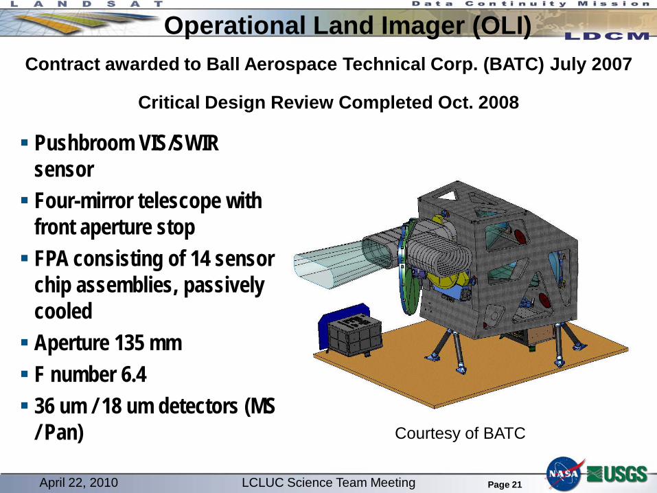
Pushbroom VIS/SWIR sensor Four-mirror telescope with
front aperture stop FPA consisting of 14 sensor
chip assemblies, passively cooled Aperture 135 mm F number 6.4 36 um / 18 um detectors (MS
/ Pan)
Contract awarded to Ball Aerospace Technical Corp. (BATC) July 2007
Critical Design Review Completed Oct. 2008
Courtesy of BATC
April 22, 2010 LCLUC Science Team Meeting
Page 22
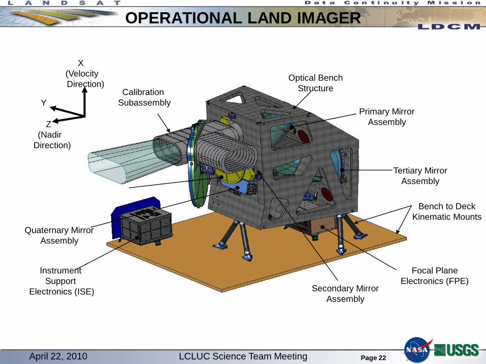
OPERATIONAL LAND IMAGER
Optical BenchStructure
Primary MirrorAssembly
Tertiary MirrorAssembly
Calibration Subassembly
Quaternary MirrorAssembly
Bench to DeckKinematic Mounts
Secondary MirrorAssembly
Instrument Support
Electronics (ISE)
X(VelocityDirection)
Y
Z(Nadir
Direction)
Focal PlaneElectronics (FPE)
April 22, 2010 LCLUC Science Team Meeting
Page 23
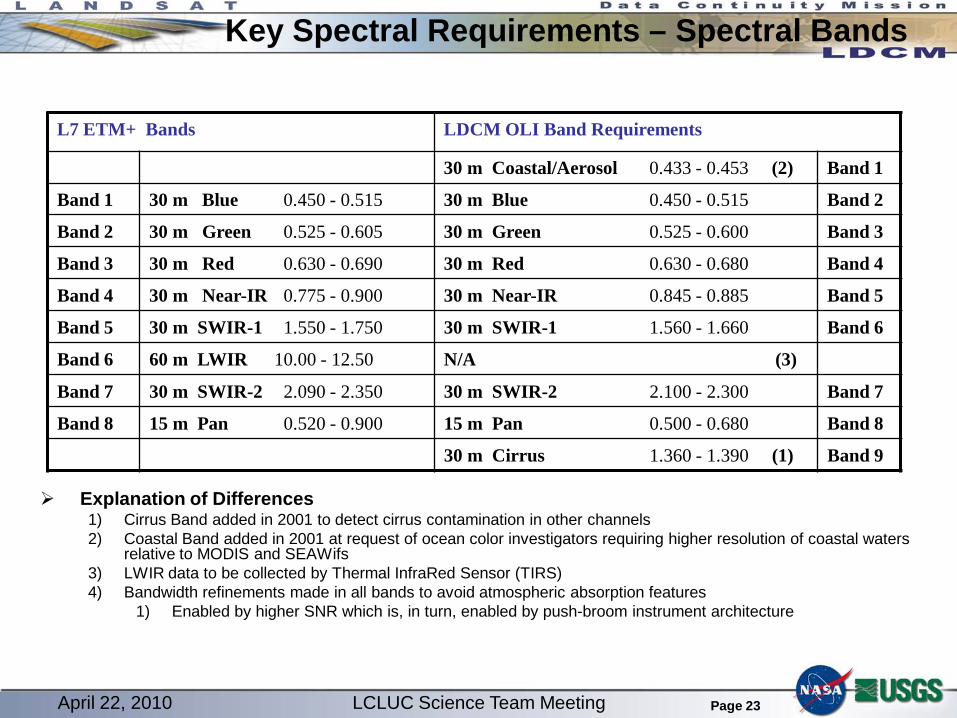
Key Spectral Requirements – Spectral Bands
Explanation of Differences1) Cirrus Band added in 2001 to detect cirrus contamination in other channels2) Coastal Band added in 2001 at request of ocean color investigators requiring higher resolution of coastal waters
relative to MODIS and SEAWifs3) LWIR data to be collected by Thermal InfraRed Sensor (TIRS)4) Bandwidth refinements made in all bands to avoid atmospheric absorption features
1) Enabled by higher SNR which is, in turn, enabled by push-broom instrument architecture
L7 ETM+ Bands LDCM OLI Band Requirements
30 m Coastal/Aerosol 0.433 - 0.453 (2) Band 1
Band 1 30 m Blue 0.450 - 0.515 30 m Blue 0.450 - 0.515 Band 2
Band 2 30 m Green 0.525 - 0.605 30 m Green 0.525 - 0.600 Band 3
Band 3 30 m Red 0.630 - 0.690 30 m Red 0.630 - 0.680 Band 4
Band 4 30 m Near-IR 0.775 - 0.900 30 m Near-IR 0.845 - 0.885 Band 5
Band 5 30 m SWIR-1 1.550 - 1.750 30 m SWIR-1 1.560 - 1.660 Band 6
Band 6 60 m LWIR 10.00 - 12.50 N/A (3)
Band 7 30 m SWIR-2 2.090 - 2.350 30 m SWIR-2 2.100 - 2.300 Band 7
Band 8 15 m Pan 0.520 - 0.900 15 m Pan 0.500 - 0.680 Band 8
30 m Cirrus 1.360 - 1.390 (1) Band 9
April 22, 2010 LCLUC Science Team Meeting
Page 24
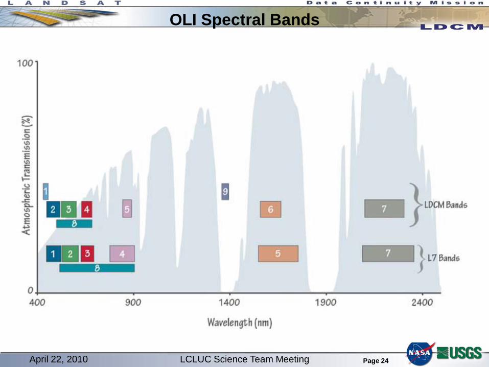
OLI Spectral Bands
April 22, 2010 LCLUC Science Team Meeting
Page 25
System Enhancements
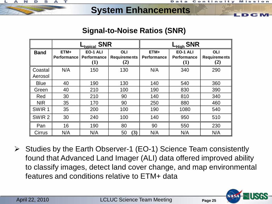
Ltypical SNR LHigh SNR Band ETM+
Performance EO-1 ALI
Performance OLI
Requirements ETM+
Performance EO-1 ALI
Performance OLI
Requirements
Coastal Aerosol
N/A 150 130 N/A 340 290
Blue 40 190 130 140 540 360 Green 40 210 100 190 830 390 Red 30 210 90 140 810 340 NIR 35 170 90 250 880 460
Studies by the Earth Observer-1 (EO-1) Science Team consistently found that Advanced Land Imager (ALI) data offered improved ability to classify images, detect land cover change, and map environmental features and conditions relative to ETM+ data
(1) (2)
(3)
(2)(1)
Signal-to-Noise Ratios (SNR)
April 22, 2010 LCLUC Science Team Meeting
Page 26
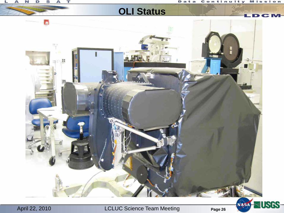
OLI Status
April 22, 2010 LCLUC Science Team Meeting
Page 27
OLI Status Flight Telescope Completed
Alignment
Thermal Vacuum
Vibration
Engineering Development Unit (EDU) Focal Plane Array Testing Completed Integration and alignment into flight telescope completed
Algorithm Development Progressing Many portions of code completed in preparation for EDU Risk Reduction Testing
April 22, 2010 LCLUC Science Team Meeting
Page 28
A Thermal InfraRed Sensor (TIRS) for the LDCM
A Phase A TIRS study was initiated by HQ at NASA Goddard Space Flight Center (GSFC) on July 1, 2008. The goal was to develop an instrument concept and implementation
approach that would not delay the planned December 2012 launch of LDCM.
The Systems Concept Review was successfully completed on October 17th, 2008
A TIRS System Requirements Review was successfully completed on February 2-3, 2009.
A TIRS Preliminary Design Review was successfully conducted May 27-28, 2009
TIRS was included in the baseline LDCM design for the mission preliminary design review in July, 2009
The TIRS critical design review is scheduled for April 27-29, 2010
April 22, 2010 LCLUC Science Team Meeting
Page 29
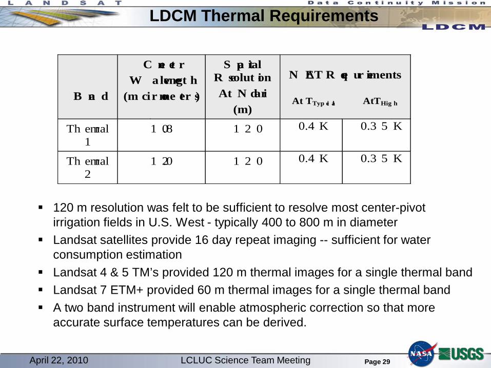
120 m resolution was felt to be sufficient to resolve most center-pivot irrigation fields in U.S. West - typically 400 to 800 m in diameter
Landsat satellites provide 16 day repeat imaging -- sufficient for water consumption estimation
Landsat 4 & 5 TM’s provided 120 m thermal images for a single thermal band Landsat 7 ETM+ provided 60 m thermal images for a single thermal band A two band instrument will enable atmospheric correction so that more
accurate surface temperatures can be derived.
B an d
C en te rW a v elengt h
(m ic r ome ter s)
S pa tialR esolut ionAt N ad ir
(m)
N E∆T R eq u ir ements
At TTyp ic al AtTHig h
Th e rmal1
1 0.8 1 2 0 0.4 K 0.3 5 K
Th e rmal2
1 2.0 1 2 0 0.4 K 0.3 5 K
LDCM Thermal Requirements
April 22, 2010 LCLUC Science Team Meeting
Page 30
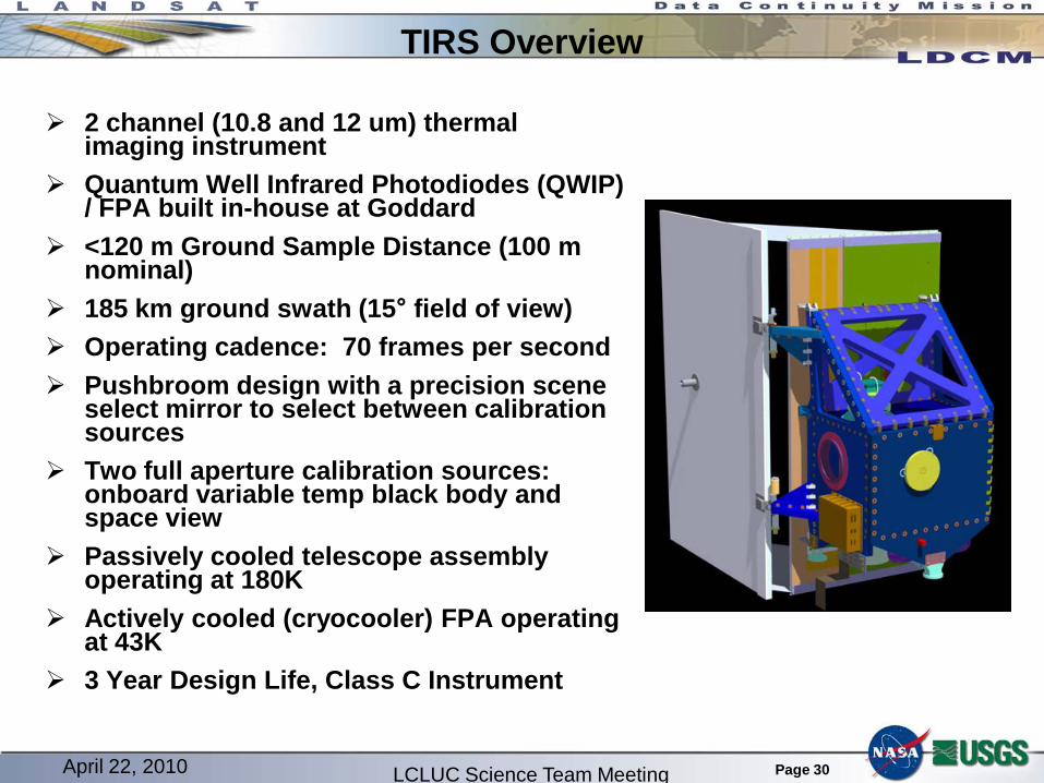
TIRS Overview
2 channel (10.8 and 12 um) thermal imaging instrument
Quantum Well Infrared Photodiodes (QWIP) / FPA built in-house at Goddard
<120 m Ground Sample Distance (100 m nominal)
185 km ground swath (15° field of view) Operating cadence: 70 frames per second Pushbroom design with a precision scene
select mirror to select between calibration sources
Two full aperture calibration sources: onboard variable temp black body and space view
Passively cooled telescope assembly operating at 180K
Actively cooled (cryocooler) FPA operating at 43K
3 Year Design Life, Class C Instrument
LCLUC Science Team MeetingApril 22, 2010
Page 31
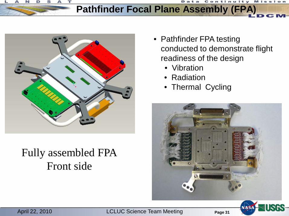
Pathfinder Focal Plane Assembly (FPA)
April 22, 2010 LCLUC Science Team Meeting
Fully assembled FPAFront side
• Pathfinder FPA testing conducted to demonstrate flight readiness of the design• Vibration• Radiation• Thermal Cycling
Page 32
TIRS Status Focal Plane Array
Successfully completed its Technical Readiness Level-6 testing– Radiation on the ROICs / QWIPs– 40 thermal cycles on the FPA– Vibration on the FPA
Flight Detectors have been selected Engineering Model FPE completed and in test
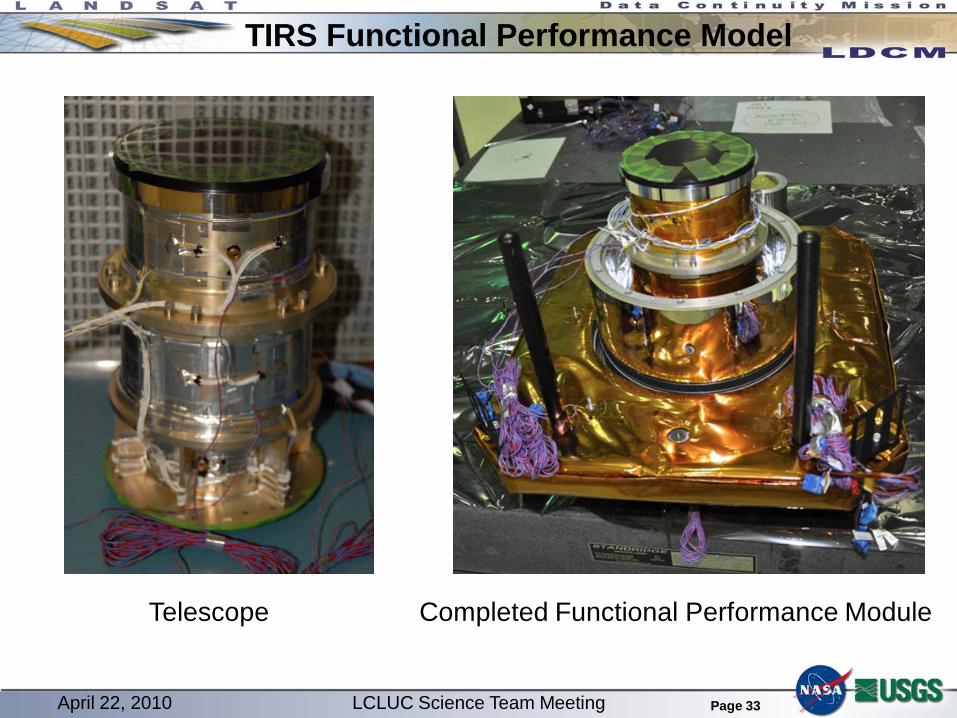
Image has been produced through the ROIC using the FPE Engineering Model TIRS Functional Performance Model in testing
Significant risk reducer for TIRS.– Includes Engineering Model telescope and FPA
Scene Select Mechanism Pathfinder scene select mirror completed through fabrication and anodization Electronics breadboard is operating and demonstrating the required stability
April 22, 2010 LCLUC Science Team Meeting
Page 33
TIRS Functional Performance Model
April 22, 2010 LCLUC Science Team Meeting
Telescope Completed Functional Performance Module
Page 34
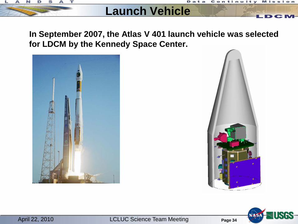
Launch Vehicle
In September 2007, the Atlas V 401 launch vehicle was selected for LDCM by the Kennedy Space Center.
April 22, 2010 LCLUC Science Team Meeting
Page 35
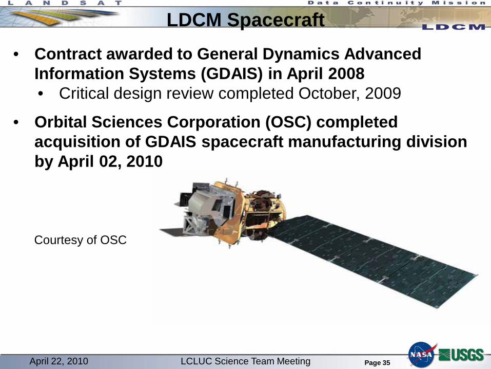
LDCM Spacecraft• Contract awarded to General Dynamics Advanced
Information Systems (GDAIS) in April 2008• Critical design review completed October, 2009
• Orbital Sciences Corporation (OSC) completed acquisition of GDAIS spacecraft manufacturing division by April 02, 2010
Ground System The LDCM ground system is in development under the
management of the USGS Earth Resources Observation and Science (EROS) Center in Sioux Falls, SD
The ground system will schedule the collection of 400 coincident OLI/TIRS scenes per day Data collection will be scheduled on the basis of a Long Term
Acquisition Plan (LTAP) modeled on the Landsat 7 LTAP to achieve seasonal coverage of the global land surface
USGS EROS will capture and archive all 400 scenes– OLI/TIRS data will also be directly transmitted from the spacecraft to
international ground stations Level 1 data products distributed at no cost to users consistent with
current data policy– Orthorectified, terrain corrected images for all OLI and TIRS spectral bands– Level 0 data (essentially raw data) will also be distributed on request
Ground System Critical Design Review held March 16 – 18 in Sioux Falls, SD
April 22, 2010 LCLUC Science Team Meeting
Page 38
Take Away Message
The NASA Agency Management Council confirmed that the LDCM is ready for the final design and fabrication phase of mission development following a Dec. 16, 2009 review. The confirmed LDCM payload now includes TIRS in addition to the OLI with development managed towards a target Dec., 2012 launch date. Mission Critical Design Review scheduled for May 25 – 27, 2010
Summary BATC is building an Operational Land Imager (OLI)
NASA GSFC is building a Thermal InfraRed Sensor (TIRS)
OSC is building the LDCM spacecraft
An Atlas V will launch the LDCM observatory
USGS will operate the observatory and will collect, archive and distribute LDCM data
– LDCM data products will merge the OLI and TIRS data