65
Gas cleaning downstream biomass gasification Status Report 2009 R.W.R. Zwart ECN-E--08-078 JUNE 2009 Who is who overview revisited in June 2009

Gas cleaning downstream biomass gasification
Status Report 2009
R.W.R. Zwart
ECN-E--08-078 JUNE 2009 Who is who overview revisited in June 2009

2 ECN-E--08-078
Abstract The government wants to help realize an affordable, reliable and clean energy economy, while fully acknowledging the role the market ought to play in this development. The role of the Energy Research Subsidy (in Dutch abbreviated as EOS) programme is to initiate and support the necessary innovation processes. The biomass research has been divided into three main areas, being (i) biorefining, (ii) electricity and heating, and (iii) gasification, gas cleaning, conditioning and syngas production. While the EOS programme can thus offer support at each of the stages of the energy innovation trajectory, it also helps the supply of knowledge to better meet the demand of the market. In order to stimulate the supply of knowledge status reports are published by relevant stakeholders upon request from the Dutch Agency for Innovation and Sustainability (SenterNovem). The status report on gas cleaning focuses on cleaning technologies downstream biomass gasifiers to manufacture clean gas, from which electricity and heat, transport fuels, chemicals and ‘new gases’ (such as SNG and hydrogen) can be produced efficiently. It provides an overview of the current status, the key players, the motives and challenges, and the ongoing remaining R&D. Although upgrading of biogas or landfill gas is not considered to be a R&D topic within the EOS research area “gasification, gas cleaning, conditioning and syngas production”, the status report at hand also provides information focused at these existing upgrading technologies. The technologies in this sector may also apply for gas obtained from thermo-chemical conversion processes.
Samenvatting Het ministerie van Economische Zaken heeft beleid ontwikkeld dat gericht is op het realiseren van een betaalbare, betrouwbare en schone energievoorziening. Een van de programma's die invulling geven aan dit beleid is Energie Onderzoek Subsidie (EOS). Het programma Energie Onderzoek Subsidie (EOS) heeft tot taak de benodigde innovatieprocessen op gang te brengen en te ondersteunen. Het aandachtsgebied Biomassa wordt opgedeeld in drie onderzoeksterreinen, te weten (i) bioraffinage, (ii) elektriciteit en warmte, en (iii) vergassing, gasreiniging, conditionering en syngasproductie. Het EOS-programma biedt ondersteuning in elk van de fasen van het energie-innovatie traject en stimuleert de noodzakelijke kennis dissiminatie. Ter stimulering van kennis dissiminatie worden door relevante belanghebbenden op verzoek van het Nederlandse agentschap voor duurzaamheid en innovate (SenterNovem) status rapporten gepubliceerd. Het status rapport over gasreiniging richt zich op nageschakelde reinigingstechnologieën achter biomassa vergassers voor de productie van schoon gas, waaruit elektriciteit en warmte, transportbrandstoffen, chemicaliën en ‘nieuwe gassen’ (zoals SNG en waterstof) op een efficiënte wijze geproduceerd kunnen worden. Het biedt een overzicht van de huidige status van de belangrijkste partijen, de motieven en uitdagingen, en lopende R&D. Hoewel de opwaardering van biogas en stortgas niet beschouwd wordt als een R&D onderwerp binnen het EOS onderzoeksprogramma “vergassing, gasreiniging, conditionering en syngas productie”, is in dit statusdocument ook aandacht besteed aan deze bestaande reinigings en conditionering technologieën. De technologieën in deze sector zouden ook toegepast kunnen worden op gas verkregen uit thermo-chemische conversie processen.
Contact For more information, please contact the author of this report: Robin Zwart Energy research Centre of the Netherlands (ECN) Unit Biomass, Coal and Environmental Research P.O. Box 1 1755 ZG Petten The Netherlands Phone: +31-224-564574 Fax: +31-224-568487 Email: [email protected] Web: www.ecn.nl (non-confidential ECN reports can be downloaded from this site)

ECN-E--08-078 3
Acknowledgement This report is prepared in commission of the Dutch Agency for Innovation and Sustainability (SenterNovem). Parts of the text, tables and figures in this report were directly copied from existing public web-sites and reports. The author is aware of and acknowledges the existing copyrights. The author also wants to thank all stakeholders and colleagues that were involved in the preparation of this report. This includes also the staff of the Technical Universities of Delft (TUD) and Eindhoven (TUe), the University of Twente (UT) and the Biomass Technology Group (BTG), with whom ECN is cooperating in the SenterNovem Long-Term Energy Research Subsidy (EOS-LT) consortium project “Biomass gasification and gas cleaning”. In particular gratitude and appreciation is expressed to John Neeft, author of the confidential ECN reports on tar formation and on tar removal techniques ECN-CX--99-132 and ECN-CX--00-125 called “Teren - Kinetiek en mechanisme van ontledingsreacties” [104] and “Teerverwijderingsmethoden” [68], to Sander van Paasen and colleagues, authors of the report on “Gasification of non-woody biomass” [99], and to Wiebren de Jong and colleagues, authors of the review report “Catalytic tar reduction in fluidized bed gasification systems” [2], on which a significant part of this report is based. The first confidential report will be updated and republished in 2009 as report ECN-E--08-087, “Tar formation in pyrolysis and gasification”.
Abbreviations and definitions Ar As received MDEA Methyl di ethanol amine
Bara Bar absolute MEA Mono ethanol amine
BFB Bubbling fluidized bed MSW Municipal solid waste
BTG Biomass technology group OLGA Oil gas washer
CAPEX Capital expenditures OPEX Operational expenditure
CCS Carbon capture and storage PAH Poly aromatic hydrocarbons
CFB Circulating fluidized bed PP Poly propylene
CGE Cold gas efficiency ppmv Parts per million on a volume basis
Daf Dry and ash free PSA Pressurized swing adsorption
Db Dry basis R&D Research and development
DEA Di ethanol amine RD&D Research, development and demonstration
ECN Energy research Centre of the Netherlands RDF Refused derived fuel
EOS Energy Research Subsidy RFTC Reverse-flow catalytic tar converter
ER Equivalence ratio (lambda) RME Rapeseed oil methyl esther
ERS Energy research subsidy RPS Rotating particle separator
ESP Electrostatic precipitator SNG Substitute natural gas
FCC Fluid cat cracker TARWATC Tar water cleaning
FICFB Fast internally circulating fluidized bed TOC Total organic carbon
FPnumber European framework program TREC Tar reduction with char
GHG Green house gas TSA Thermal swing adsorption
HC Hydrocarbons TUD Technical university of Delft
HDS Hydrodesulfurisation TUe Technical university of Eindhoven
HGF Hot gas filter TUV Technical university of Vienna
HHV Higher heating value (= Gross heating value) UT University of Twente
IGCC Integrated gasification combined cycle VPSA Vacuum pressure swing adsorption
LT Long term wt% Weight percent

4 ECN-E--08-078

ECN-E--08-078 5
Contents Abbreviations and definitions 3
List of tables and figures 6
Summary 7
1. Introduction 11 1.1 The Energy Research Subsidy (EOS) programme 11 1.2 The status report gas cleaning 11 1.3 The distinction between tar and non-tar components 11
2. Tar components 13 2.1 Tar cracking and reforming 13 2.1.1 Thermal cracking 13 2.1.2 Plasma enhanced cracking 14 2.1.3 Catalytic cracking 16
2.1.3.1 In bed materials 17 2.1.3.2 Catalytic beds and monoliths 19 2.1.3.3 Catalytic filtration 21
2.2 Physical tar removal 21 2.2.1 Electrostatic precipitators 22 2.2.2 Rotating particle separators 22 2.2.3 Cyclone separators 23 2.2.4 Filters 23 2.2.5 Water scrubber 24 2.2.6 RME scrubber 25 2.2.7 OLGA 25
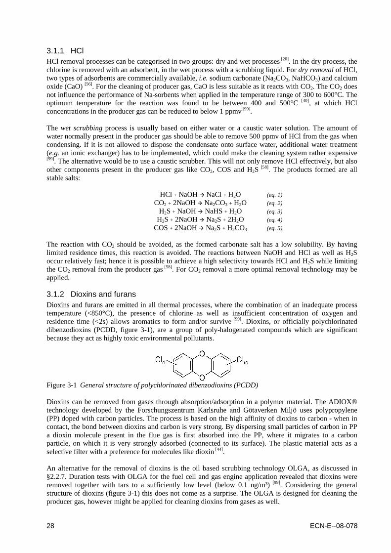
3. Non-tar components 27 3.1 Chlorine 27 3.1.1 HCl 28 3.1.2 Dioxins and furans 28 3.2 Sulfur 29 3.2.1 H2S 29 3.2.2 COS 30 3.2.3 Other organic sulphur compounds 30 3.3 Nitrogen 32 3.4 Carbon dioxide 33 3.5 Unsaturated hydrocarbons 34 3.6 Particles and alkalis 34 3.6.1 Cyclones 35 3.6.2 Barrier filters 35 3.6.3 Electrostatic filters / scrubbing technology 36
4. Biogas upgrading technologies 39 4.1 Conventional upgrading technologies 39 4.2 Issues in relation to thermo-chemical systems 40
5. Conclusions and recommendations 41 5.1 Conclusions 41 5.2 R&D issues left 41
References 43
Appendix A Tar definition and related issues 49
Appendix B Names and structures of tar compounds 51
Appendix C Who is who 59

6 ECN-E--08-078
List of tables and figures
Table 2.1 Effect of thermal tar cracking on the producer gas and the process efficiency....................... 13 Table 2.2 Summary of tar cracking catalysts advantages and disadvantages......................................... 17 Table 2.3 Experiences with granular bed filters for tar removal from biomass fuel gases..................... 23 Table 3.1 Composition of several biomass feedstocks............................................................................. 27 Table 3.2 Pros and cons of sulphur removal processes........................................................................... 29 Table 3.3 Guideline for H2S removal processes...................................................................................... 29 Table 4.1 Characteristics of conventional biogas upgrading technologies............................................. 40 Table A.1 Description of the tar classes with a focus on the tar properties and typical components...... 49 Table B.1 Names and structures of tar compounds.................................................................................. 51 Figure 2-1 Tar conversion by flame generated radicals............................................................................ 14 Figure 2-2 Start, life and disappearance of the GlidArc discharges......................................................... 14 Figure 2-3 Naphthalene conversion as a function of energy input for the corona.................................... 15 Figure 2-4 Naphthalene radical decomposition scheme............................................................................ 16 Figure 2-5 Classification and types of catalysts used for tar reduction.................................................... 16 Figure 2-6 Effect of in-bed olivine on tar formation.................................................................................. 18 Figure 2-7 Tar reforming monolith and monolith reactor unit................................................................. 20 Figure 2-8 Tar cracking catalytic filter and filter elements....................................................................... 21 Figure 2-9 ESP based tar cleaning............................................................................................................ 22 Figure 2-10 Rotating particle separator before and after testing at ECN...................................................23 Figure 2-11 Process scheme of the Harboøre process with water based tar scrubber and wet ESP.......... 24 Figure 2-12 Process scheme of the FICFB process with RME based tar scrubber.................................... 25 Figure 2-13 Process scheme of the OLGA tar removal technology............................................................ 26 Figure 2-14 Comparison of scrubbing based tar removal technologies..................................................... 26 Figure 3-1 General structure of polychlorinated dibenzodioxins (PCDD)............................................... 28 Figure 3-2 Catalytic activity for thiophene HDS versus thiophene (partial) pressure.............................. 32 Figure 3-3 Biological ammonia removal................................................................................................... 33 Figure 3-4 The mechanical principle of a cyclone.................................................................................... 35 Figure 3-5 The mechanical principle of a barrier filter............................................................................ 35 Figure 3-6 Temperature (blue line) and pressure drop (pink line) of the hot gas filter at ECN............... 36 Figure 3-7 The mechanical principle of an electrostatic filter.................................................................. 37 Figure A.1 Plugging of piping and fouling of equipment with tars ........................................................... 49 Figure A.2 Relation between the tar dewpoint and the concentration of the different tar classes............ 50

ECN-E--08-078 7
Summary
In order to stimulate the dissimination of knowledge, status reports are published by relevant stakeholders upon request from the Dutch Agency for Innovation and Sustainability (SenterNovem). The status report on gas cleaning focuses on cleaning technologies downstream biomass gasifiers to manufacture clean gas, from which electricity and heat, transport fuels, chemicals and ‘new gases’ (such as SNG and hydrogen) can be produced efficiently. This report provides an overview of the current status, the key players, the motives and challenges, and the ongoing remaining R&D. Although upgrading of biogas or landfill gas is not considered to be a R&D topic within the EOS research area “gasification, gas cleaning, conditioning and syngas production”, the status report at hand also provides information focused at these existing upgrading technologies. The technologies in this sector may also apply for gas obtained from thermo-chemical conversion processes. Gasification of biomass results in a producer gas containing numerous contaminants like dust, tar, (organic) sulphur, nitrogen and chlorine compounds, as well as alkali and heavy metals. Although concentrations could be relatively low depending on the feedstock used and the type of gasifier applied, at least some of these contaminants have to be destructed or removed upstream the final application of the producer gas, whether it is a boiler, gas engine or turbine, fuel cell or synthetic application. Hence, gas cleaning is inevitable in general, whether it is on tar components or non-tar components. Still not many gasifiers are operating commercially on biomass feedstock, in particular when not taking into account those gasification systems (co-)firing the product straight into boilers. The need for gas cleaning, and in particular tar removal technology, for CHP or synthesis purposes is still the Achilles heel of biomass gasification and gas cleaning. Standard technology has proven to be insufficient for tar destruction or removal and has lead to years of (still ongoing) RD&D on thermal and catalytic tar cracking as well as (advanced) scrubbing technologies. For the moment, the latter ones seem to have made the biggest progress, with operating biomass based CHP plants at e.g. among others Harboøre and Güssing, and water as well as organic liquid (RME, oil) based technologies being commercially available. A step by step approach could be considered in which technology is scaled up gradually. There has been a tendency to construct large (demonstration) facilities hoping that these are operated successfully and due to scale are commercially attractive as well. The risks are high though, as solving unexpected issues will require enormous budgets. The risk that such a plant becomes mothballed instead of a commercial success has been proven to be relevant. Examples of this are the 180 ton per day Battelle gasification plant in Burlington, USA, and the 8 MWe ARBRE combined-cycle plant in Eggborough, UK. Similar to tar removal technology, standard commercially available technology for removal of non-tar components up to now has also proven to be insufficient, in particular for critical applications of the producer gas in fuel cells or synthesis applications. Part of that has to do with upstream tar removal to be either insufficient (i.e. to low efficiencies of the tar removal) or not designed for the more stringent producer gas specifications for these applications (i.e. trace tar components still present in the gas). Another part of that is caused by the presence of gas contaminants previously not considered problematic for CHP applications (e.g. organic sulfur, dioxins). As can be expected, the biggest progress towards gas cleaning for non-tar components is made by those who are skilful at tar removal. Over the years there has been a tendency for biomass gasification and gas cleaning to apply conventional technology or mimic coal gasification systems. For the gasification process this philosophy already has been dropped. Also the need for pressurised biomass gasification seems to be abandoned, argued by the complexity of biomass feeding. All commercially running biomass based gasifiers operate at (near) atmospheric pressure, not at the pressure levels of 30 bars and higher, typical for coal and oil based gasifiers.

8 ECN-E--08-078
Concerning gas cleaning, whether it is removal of tars or non-tar components, the operating conditions for commercially available conventional technology (e.g. coal based) will differ significantly from the conditions downstream a biomass gasifier, hence the feasibility of conventional technology will have to be reconsidered or at least tested it in realistic conditions. It might well be that conventional technology is not suitable for biomass based processes. One of the lessons learned most in RD&D of gas cleaning is that conventional technology is not always applicable without any problems in thermo chemical conversion of biomass. Not only will the producer gas always contain unfamiliar (trace) components, also in many cases operating conditions like temperature and in particular pressure will be different from the conventional operating conditions of the technology just because it is not (yet) possible to operate the thermo chemical conversion process at these conditions. For that reason, it makes sense to test conventional technology first on realistic “biomass based” gases and conditions before installing them on large scale. It could be that due to the different gases and conditions (for the moment) thermo chemical biomass conversion systems need different technologies than bio chemical conversion systems or even thermo chemical coal conversion systems and these have to be developed step by step. A step by step approach becomes even more important for systems with multiple process steps, e.g. biomass gasification based synthesis systems like the production of Substitute Natural Gas (SNG), DME and Fischer-Tropsch (FT) diesel. For the successful development of these complex systems, slipstream testing of the critical catalytic components in gas cleaning and synthesis in an upscaled (demonstration) CHP plant consisting of the upstream gasifier and tar removal could benefit the RD&D of the whole system, as it enables long duration tests with the critical components under realistic gas conditions.

ECN-E--08-078 9
Samenvatting
Ter stimulering van kennis dissiminatie worden door relevante belanghebbenden op verzoek van het Nederlandse agentschap voor duurzaamheid en innovate (SenterNovem) status rapporten gepubliceerd. Het status rapport over gasreiniging richt zich op nageschakelde reinigings technologieën achter biomassa vergassers voor de productie van schoon gas, waaruit elektriciteit en warmte, transportbrandstoffen, chemicaliën en ‘nieuwe gassen’ (zoals SNG en waterstof) op een efficiënte wijze geproduceerd kunnen worden. Het biedt een overzicht van de huidige status van de belangrijkste partijen, de motieven en uitdagingen, en lopende R&D. Hoewel de opwaardering van biogas en stortgas niet beschouwd wordt als een R&D onderwerp binnen het EOS onderzoeksprogramma “vergassing, gasreiniging, conditionering en syngas productie”, is in dit statusdocument ook aandacht besteed aan deze bestaande reinigings en conditionering technologieën. De technologieën in deze sector zouden ook toegepast kunnen worden op gas verkregen uit thermo-chemische conversie processen. Vergassing van biomassa leidt tot de productie van gas met tal van verontreinigingen zoals stof, teer, (organisch) zwavel, stikstof en chloorverbindingen, evenals alkali en zware metalen. Hoewel de concentraties relatief gering kunnen zijn, afhankelijk van de gebruikte brandstof en de aard van de vergasser toegepast, dient minimaal een aantal van deze componenten omgezet of verwijderd te worden voordat het gas ingezet kan worden, hetzij in een ketel, gasmotor of turbine, brandstofcel of synthetische toepassing. Met andere woorden, normaliter is gasreiniging onvermijdelijk, of het nu verontreinigingen in de vorm van teer componenten of niet-teer componenten betreft. Commercieel gezien worden er nog weinig vergassers op biomassa bedreven, zeker wanneer geen rekening wordt gehouden met de (co-)vergassing systemen waarbij het productgas rechtstreeks omgezet wordt in ketels ten behoeve van warmte productie. De gasreiniging, en met name het verwijderen van teren, voor WKK of synthese doeleinden is nog steeds de achilleshiel van biomassa vergassing. Conventionele technologie heeft bewezen onvoldoende teren om te zetten of te verwijderen en heeft geleid tot jaren van (nog steeds voortdurende) RD&D op het gebied van thermisch en/of katalytisch kraken van teer alsook op het gebied van (geavanveerde) wastechnologieën. Vooralsnog is in de wastechnologieën de grootste vooruitgang geboekt, met de werkende WKK-installaties van onder andere Harboøre en Güssing als voorbeeld. Wastechnologieën gebaseerd op water alsmede organische vloeistoffen (RME, olie) zijn commercieel verkrijgbaar. Voor de ontwikkeling en opschaling van technologieën kan een stapsgewijze benadering gehanteerd worden. Het is een tijd lang de tendens geweest om direct grote (demonstratie) plants te bouwen in de hoop dat deze direct succesvol bedreven konden worden en tevens commercieel gezien aantrekkelijk konden zijn. De risico’s hierbij zijn echter groot, en het oplossen van problemen vereist veel tijd en geld. Het risico bestaat dat een dergelijke installatie als gevolg hiervan wordt stilgelegd, in plaats van dat het een commercieel succes wordt. Voorbeelden hiervan zijn de 180 ton per dag Battelle vergasser in Burlington in de Verenigde Staten van Amerika en de 8 MWe ARBRE STEG in Eggborough in het Verenigd Koninkrijk. Vergelijkbaar met de teerverwijdering, is toepassing van conventionele gasreiniging voor de verwijdering van niet-teer verontreinigingen tot nu toe onvoldoende succesvol geblemen, met name daar waar het de reiniging betreft voor de meer kritische toepassingen van het product gas, i.e. in brandstofcellen of synthetische processen. Deels heeft dit te maken met een onvoldoende functionerende teer verwijdering, anderzijds met het altijd nog aanwezig zijn van sporen van teercomponenten. Daarnaast bevat het product gas vaak nog een aantal additionele verontreinigingen, voor WKK-toepassingen niet als een probleem worden beschouwd (bv. organische zwavelverbindingen, dioxines), maar voor katalytische processen schadelijk kunnen zijn. Zoals kan worden verwacht wordt de grootste vooruitgang in de reiniging van deze niet-teer componenten gemaakt door degenen die op in staat zijn eerst in voldoende mate teren uit het productgas te verwijderen.

10 ECN-E--08-078
In de loop der jaren is er altijd een trend geweest om voor vergassing van biomassa en reiniging van het productgas gebruik te maken van conventionele technologieën en kolen gebaseerde systemen. Voor de daadwerkelijke vergassing van biomassa lijkt deze filosofie al te zijn vervallen. Ook de behoefte aan drukvergassing van biomassa lijkt te zijn vervallen, dit ten gevolge van de complexiteit van de voeding van de biomassa. Alle commerciële biomassa vergassers werken op (bijna) atmosferische druk, en niet op een (voor kolen of olie vergassers typische) druk van 30 bar en hoger. Met betrekking tot de gasreiniging, of het nu de teer of de niet-teer componenten betreft, lijken de bedrijfscondities voor biomassa systemen dusdanig te verschillen met die voor kolen systemen, dat de toepassing van conventionele technologieën heroverwogen zou moeten worden of dat minimaal de conventionele technologie onder voor biomassa systemen realistische omstandigheden getest zou moeten worden. Het kan goed zijn dat de conventionele technologie uiteindelijk niet geschikt blijkt te zijn voor biomassa gebaseerde processen. Een van de grootste lessen in RD&D op het gebied van gasreiniging is wel dat conventionele technologie niet altijd zonder problemen toegepast kan worden in biomassa gebaseerde thermochemische conversie systemen. Niet alleen zal het productgas altijd sporen bevatten aan specifieke verontreiningingen, in veel gevallen zullen de bedrijfscondities zoals temperatuur en druk afwijken van de bedrijfscondities waarvoor de conventionele technologie was ontwikkeld en ontworpen, simpelweg omdat de thermochemische conversie van biomassa onder andere condities plaats vindt dan de biochemische conversie of de thermochemische conversie van kolen. Om die reden is het zinvol om conventionele technologie eerst te testen op realistisch productgas voordat deze grootschalig geïmplementeerd wordt. Het zou kunnen zijn dat als gevolg van de afwijkende samenstelling en condities van het productgas biomassa gebaseerde thermochemische conversie systemen (in eerste instantie) een gasreiniging vergt die afwijkt van de conventionele gasreiniging voor bio-chemische conversie systemen of zelfs thermo chemische omzetting van kolen. Stapsgewijze ontwikkeling en opschaling van dergelijke nieuwe technologieën kan hierbij van groot belang zijn, zeker voor systemen met meerdere nageschakelde processtappen, zoals synthetische processen voor de productie van Substitute Natural Gas (SNG), DME en/of Fischer-Tropsch (FT) diesel. Om tot een succesvolle ontwikkeling te komen van dergelijke complexe systemen kan het verstandig zijn om de kritische componenten in (katalytische) gasreiniging en synthese te testen in een slipstream van een bestaande opgeschaalde (demonstratie) WKK-installatie, bestaande uit de juiste vergasser en basis gasreiniging. De RD&D op het gebied van de noodzakelijke nageschakelde processstappen kan op die manier veel efficiënter plaatsvinden, aangezien de mogelijkheid bestaat om de kritische processtappen gedurende langere tijd onder realistische omstandigheden te kunnen testen.

ECN-E--08-078 11
1. Introduction
1.1 The Energy Research Subsidy (EOS) programme The government wants to help realize an affordable, reliable and clean energy economy, while fully acknowledging the role the market ought to play in this development. The role of the Energy Research Subsidy (EOS) programme is to initiate and support the necessary innovation processes. In some cases the market itself is already moving fast. The only help that may be needed then is with demonstrating a new technology. In other cases an idea may be in an early stage. Then the road to market introduction may be a long one and often help will be wanted. Biomass energy research is extremely important in achieving the aforementioned objectives. This research has been divided into three main areas, being (i) biorefining, (ii) electricity and heating, and (iii) gasification, gas cleaning, conditioning and syngas production. While the EOS programme can thus offer support at each of the stages of the energy innovation trajectory, it also helps the supply of knowledge to better meet the demand of the market.
1.2 The status report gas cleaning
In order to stimulate the supply of knowledge status reports are published by relevant stakeholders upon request from the Dutch Agency for Innovation and Sustainability (SenterNovem). The status report on gas cleaning focuses on cleaning technologies downstream biomass gasifiers to manufacture gaseous semi-manufactured products, whereby electricity and heat, transport fuels, chemicals and ‘new gases’ (such as SNG and hydrogen) can be produced efficiently. It provides an overview of:
� Current status � Key players � Motives and Challenges � Required R & D work
Although upgrading of biogas or landfill gas is not considered to be a R&D topic within the EOS research area “gasification, gas cleaning, conditioning and syngas production”, the status report at hand also provides information focused at these existing upgrading technologies. The technologies in this sector may also apply for gas obtained from thermo-chemical conversion processes.
1.3 The distinction between tar and non-tar components In the status report gas cleaning 2009, the above points are reported. The report is divided into two main sections, one discussing the issues concerning tar contaminants still being considered the Achilles heel of biomass gasification, and the other the issues concerning the remaining non-tar contaminants. For both the tar and the non-tar components, the report includes an overview of the current state of research, development and demonstration in the field of gas cleaning, both in the Netherlands, Europe and globally. A description of (i) commercial facilities, (ii) pilot and demonstration initiatives, and (iii) research and development is the main part of the report. A distinction is made between technologies focussing on tar components (chapter 2) and non-tar components (chapter 3), with a description of tars and the main associated issues included in the appendices. The similarities with conventional technologies for upgrading biogas or landfill gas are described in chapter 4. The conclusions and recommendations are given in chapter 5 of this status report. An overview of who is who in the field of gas cleaning is provided appendix C of this status report. If an update of this overview is considered to be necessary in time, the author will adjust the digital version of this report and will make it available via the publications website of the Energy research Centre of the Netherlands (www.ecn.nl/publications).

12 ECN-E--08-078
ECN-E--08-078 13
2. Tar components
Tars are still considered to be the major bottleneck or even stumbling blocks in the application of biomass gasification [2][10]. This holds for fluidised as well as updraft fixed bed based gasification performed at temperatures well below 1000°C, as tar contents in the raw gas can be up to several tens of g/mn³. A description of tars and the main associated issues are included in the appendices. The cleaning from these organic species down to values that are acceptable for different downstream processes is of crucial importance for successful implementation of biomass gasification technology. Tar reduction measures can be classified in three main categories, being (i) tar cracking and reforming, (ii) mechanical tar removal and (iii) physical tar removal. In the following paragraphs, these measures are discussed and compared.
2.1 Tar cracking and reforming
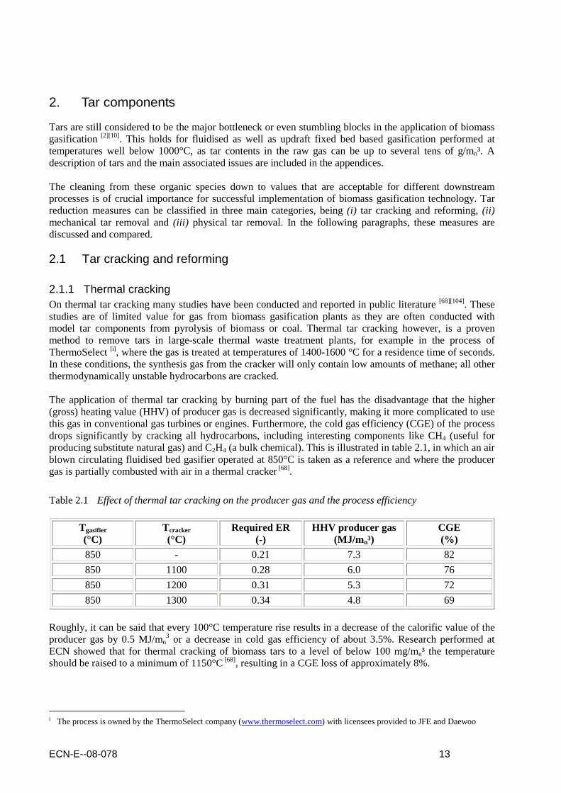
2.1.1 Thermal cracking On thermal tar cracking many studies have been conducted and reported in public literature [68][104]. These studies are of limited value for gas from biomass gasification plants as they are often conducted with model tar components from pyrolysis of biomass or coal. Thermal tar cracking however, is a proven method to remove tars in large-scale thermal waste treatment plants, for example in the process of ThermoSelect [i] , where the gas is treated at temperatures of 1400-1600 °C for a residence time of seconds. In these conditions, the synthesis gas from the cracker will only contain low amounts of methane; all other thermodynamically unstable hydrocarbons are cracked. The application of thermal tar cracking by burning part of the fuel has the disadvantage that the higher (gross) heating value (HHV) of producer gas is decreased significantly, making it more complicated to use this gas in conventional gas turbines or engines. Furthermore, the cold gas efficiency (CGE) of the process drops significantly by cracking all hydrocarbons, including interesting components like CH4 (useful for producing substitute natural gas) and C2H4 (a bulk chemical). This is illustrated in table 2.1, in which an air blown circulating fluidised bed gasifier operated at 850°C is taken as a reference and where the producer gas is partially combusted with air in a thermal cracker [68].
Table 2.1 Effect of thermal tar cracking on the producer gas and the process efficiency
Tgasifier (°C)
Tcracker (°C)
Required ER (-)
HHV producer gas (MJ/m n³)
CGE (%)
850 - 0.21 7.3 82
850 1100 0.28 6.0 76
850 1200 0.31 5.3 72
850 1300 0.34 4.8 69
Roughly, it can be said that every 100°C temperature rise results in a decrease of the calorific value of the producer gas by 0.5 MJ/mn
3 or a decrease in cold gas efficiency of about 3.5%. Research performed at ECN showed that for thermal cracking of biomass tars to a level of below 100 mg/mn³ the temperature should be raised to a minimum of 1150°C [68], resulting in a CGE loss of approximately 8%.
i The process is owned by the ThermoSelect company (www.thermoselect.com) with licensees provided to JFE and Daewoo

14 ECN-E--08-078
At the Technical University of Eindhoven (TUe) in recent years research also has been carried out towards non-catalytic partial oxidation with the aim to reduce biomass gasification gas tar contents [51][52]. Experiments were performed within the temperature range of 900-1150°C and a residence time varying between 1 and 12 seconds. Brandt [22] reports temperatures and residence times needed of 1250°C and 0.5 seconds, respectively. In line with this result is the study of non-catalytic partial oxidation at FZ Karlsruhe [54][55]. This would lead to the disadvantages of the use of expensive alloys for the tar cracker and, moreover, significant exergy losses in the system. Also, soot is reported to be produced in this tar cleaning method. Recently, the Nexterra company [ii] announced that they had been running such a system in a slipstream of their pilot-plant updraft gasifier in Kamloops and are aiming on installing a gas engine downstream. The research at the TUe now focuses on the working mechanisms behind partial oxidation in order to acquire the additional knowledge needed to optimize this technology [103]. In tar conversion by partial oxidation, observations are made indicating the significant role of oxygen radicals. The objective of this research is to map the influence of radicals on tar conversion at high temperature immediately after the gasifier unit and to develop a novel technology that combines the benefits of existing technologies. The basic idea behind the tar conversion by flame generated radicals is presented in figure 2-1.
Figure 2-1 Tar conversion by flame generated radicals
2.1.2 Plasma enhanced cracking Conventional gliding discharges are produced between two horn shaped electrodes placed in a relatively fast gas flow in the direction of the flow. They start at the spot where the distance between the electrodes is shortest, and spread by gliding progressively along the electrodes in the direction of flow until they disappear by themselves after a certain path. Figure 2-2 gives a schematically presentation of the GlidArc process [30], with the gas flowing from the bottom (injection point) to the top. In the gliding discharge, highly energetic electrons are produced, which results in species like ions, secondary electrons, UV radiation, radicals, excited molecules and molecules with attached electrons. This reactive medium, the plasma, is in this project used for the conversion of tar.
Figure 2-2 Start, life and disappearance of the GlidArc discharges
ii Communication with Nesho Plavsic during the 2008 Montreal IEA meeting for Bioenergy Task 33 on biomass gasification

ECN-E--08-078 15
The GlidArc plasma is combined thermal and cold plasma. About 20% of the energy is dissipated in the thermal part and 80% in the cold part [32]. The thermal part of the plasma is responsible for the plasma activity; in the cold part radicals are responsible for the removal of tars, similar as in the partial oxidation process. The production of radicals in a plasma process is facilitated by electrons in the plasma. The energy level of the electrons must be high enough in order that molecular bonds can be broken and radicals be produced in the plasma. For the GlidArc process the energy level of the electrons in the cold plasma revealed to be too low, as a result of which production of radicals is restricted and in addition the functionality for the removal of tars is too low. The tar conversion in the GlidArc reactor was during tests at ECN at most 40% [100]. Another reason for the low conversion is that the GlidArc plasma does not show any selectivity towards hydrocarbons, not even with increasing temperature. As a result, tar-like compounds as well as other hydrocarbons like methane, ethane, ethylene and benzene are equally converted [100], hence requiring significant amounts of energy for conversion of tars. In contrast to the poor tar removal results in biomass fuel gas, high conversions can be obtained for the removal of hydrocarbons like toluene and xylene in air [32]. This can be explained by the fact that plasma in air facilitates low-temperature oxidation. Oxygen and in particular nitrogen radicals play an important role in this process, so the air is essential for the efficiency of the plasma assisted hydrocarbon decomposition. Recent research at the TUe revealed that in absence of nitrogen radicals, conversion is far less, possibly due to the fact that the oxygen radicals (unlike nitrogen radicals) can cause reformation of tars as well. In the commercial plasma processes constructed by e.g. the Plasco Energy Group [iii] the generated arc is pushed into a furnace by means of air, hence creating the right conditions. No results on the Plasco plant are published though up till now. In producer gas, the hydrocarbons cannot be “ignited” as the reaction rate with CO2 or H2O is much lower than the reaction rate with air. Therefore, the conversions are much lower
[100]. An alternative to the GlidArc plasma is a thermal plasma reactor, removing tars at high temperature. An advantage of this plasma reactor in comparison with a thermal tar cracker is the fast and good controllability of the temperature in the reactor without diluting the gas with inert compounds like N2 and CO2. Due to the high consumption of electric energy, a sole thermal plasma reactor, however, can not compete energetically with a thermal tar cracker. At the TUe research is done on fully non-thermal corono plasma for tar removal. The major advantage of using non-thermal plasma is to do chemical conversion of tars at low temperatures and solely rely on the generation of high energy electrons which dissociate molecules and thereby creates the necessary reactive environment. Experimental results have indicated complete conversion of tar by pulsed plasma processing at lower temperature [69]. The investigations also indicate that the gaseous environment, e.g. the presence of nitrogen, has strong influence on tar cracking reactions. As such, it can be expected that tar conversion in producer gas becomes less, in particular for gasifiers producing a gas with initial higher heating value (figure 2-3).
Figure 2-3 Naphthalene conversion as a function of energy input for the corona
iii The Plasco Energy Group completed a plasma-arc waste demonstration plant in Ottawa, Canada at the Trail Road Landfill, to process 85 tonnes per day of municipal solid waste MSW (www.plascoenergygroup.com)

16 ECN-E--08-078
The explanation for the conversion of tars being less efficient in realistic producer gases might be found in the tar decomposition scheme e.g. that of naphthalene as presented in figure 2-4 [69]. The H and OH radicals can cause the desired decomposition of the naphthalene; however can also result in the reformation of naphthalene from the intermediate tar radicals. Hence, the more H and OH radicals one might expect present in the producer gas, the less the tar conversion efficiency will be.
Figure 2-4 Naphthalene radical decomposition scheme
2.1.3 Catalytic cracking Catalytic tar cleaning is potentially attractive as no additional energy input may be required and hence thermodynamic efficiency losses can be kept to a minimum [2]. Abu El-Rub [1] reviewed different tar cracking catalysts (figure 2-5), with the advantages and disadvantages summarized in table 2.2 .
Figure 2-5 Classification and types of catalysts used for tar reduction
Mineral Synthetic
Iron
ores
Clay m
inerals
Olivin
e
Calcin
ed ro
cks
Activated
alum
ina
Alkali m
etal carb
on
ates F
CC
catalysts
Ch
ar
Tran
sition m
etals b
ased
Calcite
Mag
nesite
Calcin
ed do
lom
ite
Ni-b
ased
Pt,Z
r,Rh
,Ru,F
e-based
versus

ECN-E--08-078 17
In this paragraph three different systems for catalytic tar cracking are discussed, based on addition of catalytic materials to the bed material of the gasifier (§2.1.3.1) or application of catalytic beds, monoliths or filters downstream the gasifier (§2.1.3.2 and 2.1.3.3).
Table 2.2 Summary of tar cracking catalysts advantages and disadvantages
Catalyst Advantages Disadvantages Calcined rocks
Inexpensive and abundant Attain high tar conversion ~95% conversion with dolomite Often used as guard beds for expensive catalysts Most popular for tar reduction
Fragile materials and quickly eroded from fluidized beds
Olivine
Inexpensive High attrition resistance
Lower catalytic activity than dolomite
Clay minerals
Inexpensive and abundant Less disposal problems
Lower catalytic activity than dolomite Most natural clays do not support the high temperatures (>800ºC) needed for tar reduction (lose pore structure)
Iron ores
Inexpensive Abundant
Rapidly deactivated in absence of hydrogen Lower catalytic activity than dolomite
Char
Inexpensive Natural production inside the gasifier High tar conversion comparable to dolomite
Consumption because of gasification reactions Biomass char properties not fixed and depends on biomass type and process conditions
FCC
Relatively cheap but not cheaper than the above More knowledge is known about it from the experience with FCC unit
Quick deactivation by coke Lower catalytic activity than dolomite
Alkali metals
Natural production in the gasifier Reduce ash handling problem when used as a catalyst
Particle agglomeration at high temperatures Lower catalytic activity than dolomite
Activated alumina
High tar conversion comparable to dolomite Quick deactivation by coke
Transition metals
Able to attain complete tar reduction at ~ 900²C Increase the yield of CO and H2 Ni-based 8 to 10 times more active than dolomite
Rapid deactivation because of sulfur and high tar content in the feed Relatively expensive
2.1.3.1 In bed materials Natural minerals Rock materials like dolomite and limestone are well known as catalytically active bed materials [2], in particular in their porous calcined form. Especially, the dolomites are among the most active and most widely used. They are comparatively active in tar conversion (up to 95%), cheap and are considered to be disposable, which is surely advantageous and this explains their popularity. The catalytic tar reduction potential however strongly depends on morphology factors (pore size, surface area) and content of other metals. Disadvantages are that the material is heterogeneous in nature (differing per region) and in particular that it is soft and thus relatively high attrition rates can be observed [35][43][87], leading to losses and increased solids loads to the gas cleaning. Furthermore, calcination is necessary for sufficient reactivity which involves significant energy input. Deactivation of calcined rock material is attributed to (i) carbon deposition and (ii) re-carbonation when CO2 partial pressures are too high in the system [81][82]. In the 500 kWth air-blown CFB gasifier at Umsicht, Germany, operating at 910-920°C the use of fresh dolomite led to tar concentrations in the gas of about 300 mg/mn³, however used dolomite resulted in values up to 2.5 g/mn
3 [53]. This in-time degradation effect is comparable with the data published by Cutec for their steam/O2 blown 400 kWth CFB gasifier [77]. Here, also, it was indicated that compared to the use of sand, dolomite showed the best reduction of tar. However, still values of 3.5 g/mn3 were reported in the raw gas, which is significantly higher than reported by Ising [53] concerning the Umsicht CFB gasifier. Possibly this is an example of the heterogeneous nature of the dolomite used; also the different oxidizer could play an important role as an explanation for the difference observed. Companies having used, or still using the technology of in-bed use of calcined rock material are TPS, Carbona Inc., Foster Wheeler and Repotec (the latter at the Güssing plant in specific test campaigns).
18 ECN-E--08-078
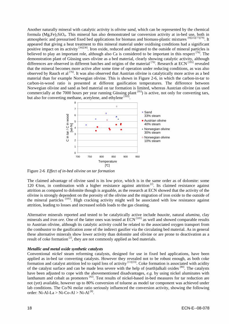
Another naturally mineral with catalytic activity is olivine sand, which can be represented by the chemical formula (Mg,Fe)2SiO4. This mineral has also demonstrated tar conversion activity at in-bed use, both in atmospheric and pressurised fixed bed applications for biomass and biomass-plastic mixtures [9][25][77][79]. It appeared that giving a heat treatment to this mineral material under oxidising conditions had a significant positive impact on its activity [36][38]. Iron oxide, reduced and migrated to the outside of mineral particles is believed to play an important role, although also Ca is considered to be important in this respect [76]. The demonstration plant of Güssing uses olivine as a bed material, clearly showing catalytic activity, although differences are observed in different batches and origins of the material [76]. Research at ECN [105] revealed that the mineral becomes more active after some time of operation under reducing conditions, as was also observed by Rauch et al [76]. It was also observed that Austrian olivine is catalytically more active as a bed material than for example Norwegian olivine. This is shown in Figure 2-6, in which the carbon-in-tar to carbon-in-wood ratio is presented at different gasification temperatures. The difference between Norwegian olivine and sand as bed material on tar formation is limited, whereas Austrian olivine (as used commercially at the 7000 hours per year running Güssing plant [95]) is active, not only for converting tars, but also for converting methane, acetylene, and ethylene [105].
0
1
2
3
4
5
6
7
8
700 750 800 850 900 950
Temperature[°C]
C in
tar
/ C in
woo
d [w
t-%
]
Sand 33% steam
Austrian olivine 40% steam
Norwegian olivine30% steam
Norwegian olivine10% steam
Figure 2-6 Effect of in-bed olivine on tar formation The claimed advantage of olivine sand is its low price, which is in the same order as of dolomite: some 120 €/ton, in combination with a higher resistance against attrition [2]. Its claimed resistance against attrition as compared to dolomite though is arguable, as the research at ECN showed that the activity of the olivine is strongly dependent on the porosity of the olivine and the migration of iron oxide to the outside of the mineral particles [105]. High cracking activity might well be associated with low resistance against attrition, leading to losses and increased solids loads to the gas cleaning. Alternative minerals reported and tested to be catalytically active include bauxite, natural alumina, clay minerals and iron ore. One of the latter ones was tested at ECN [105] as well and showed comparable results to Austrian olivine, although its catalytic activity could be related to the associated oxygen transport from the combustor to the gasification zone of the indirect gasifier via the circulating bed material. As in general these alternative minerals show lower activity than dolomite and olivine or are prone to deactivation as a result of coke formation [2], they are not commonly applied as bed materials. Metallic and metal oxide synthetic catalysts Conventional nickel steam reforming catalysts, designed for use in fixed bed applications, have been applied as in-bed tar converting catalysts. However they revealed not to be robust enough, as both coke formation and catalyst attrition led to rapid loss of activity [11][33]. Coke formation is associated with acidity of the catalyst surface and can be made less severe with the help of (earth)alkali oxides [80]. The catalysts have been adjusted to cope with the abovementioned disadvantages, e.g. by using nickel aluminates with lanthanum and cobalt as promoters [42]. Test results of nickel-based in-bed measures for tar reduction are not (yet) available, however up to 80% conversion of toluene as model tar component was achieved under lab conditions. The Co/Ni molar ratio seriously influenced the conversion activity, showing the following order: Ni-Al-La > Ni-Co-Al > Ni-Al [8].

ECN-E--08-078 19
Nickel has also been used to enrich the natural mineral olivine, creating a hybrid between natural material and artificial catalyst, making it more stable than the conventional artificial catalysts. Using up to 40 wt% of this material in an olivine bed led to about 75% decrease of tar content in the gas. The catalyst showed no noticeable deactivation in two tests with a fluidized bed biomass steam gasifier of 30 and 45 h, respectively [27][28][70][75]. At the University of Tsukuba, Japan, a ruthenium based catalyst (Rh/CeO2/SiO2) has been tested as an in-
bed catalyst [3][4][5][6][7] . The addition of the SiO2 prevented sintering of the catalyst, which was the biggest issue in tests with the Rh/CeO2 based predecessor. Although no long-term tests were performed (yet), the indications are positive for this catalyst as practically no coke formation is observed and tar concentration in the final producer gas is reported to be negligible.
2.1.3.2 Catalytic beds and monoliths As with in-bed materials, natural minerals and metallic and metal oxide synthetic catalysts can be used for tar conversion in downstream reactors. In this paragraph the progress made in tar conversion in downstream catalytic beds and monoliths is summarised. Natural minerals As described in §2.1.3.1 naturally occurring minerals are relatively cheap materials, and are disposable. Their softness and attrition rate are downsides. Also, chlorine present in the biomass fuel may react with CaO to produce CaCl2 and thus reduce the catalytic activity [2]. A substantial amount of research on downstream beds with dolomite and limestone has been carried out worldwide by numerous companies and research institutes. The Swedish Company TPS applies this technology for tar reduction using calcined dolomite (together with oxygen) in a circulating fluidized bed situated downstream of the main air-blown biomass CFB gasifier [78]. Other natural minerals applied for downstream cleaning of tar components are bauxite (Al2O3/Fe2O3), bentonite (CaO/Al2O3/SiO2) and other natural mixed oxides [53]. With inlet concentrations of real tar of the 500 kWth Umsicht CFB gasifier, more than 95% conversion of tars was obtained with the dolomites and the bauxite, and about 75% with the bentonite. Char By using char as a catalyst for tar cracking a cheap material is used that is already available in large quantities from the biomass fuel itself. At Twente University as well as Karlsruhe University tests were performed showing that naphthalene conversions at 900°C were practically 100%. At 750°C with typical air-blown gasification gas compositions conversion above 95% was obtained with only little char being consumed [1][60]. Tests at ECN with the TREC [iv] reactor showed though that although char was able to reduce tars (with approximately 75%) it was not very selective for heavy tars. Performance could only be improved by applying more catalytically active bed materials like natural minerals [97]. Metallic and metal oxide synthetic catalysts Among the artificial catalysts of the transition metal type, applied in downstream beds, nickel based ones are the most popular. Most commercial steam reforming catalysts being supplied by for example BASF, ICI, UCI, Haldor Topsøe and Südchemie all contain this element to a large extent [2]. Corella et al. [26] tested several commercial catalysts for the purpose of biomass gasification gas upgrading. They indicated changes in the main gas constituents occurring with the formation and destruction of methane. When applied at temperatures significantly lower than 900°C, sulfur species in the gasification gas had a poisonous impact on the catalyst activity and a negative effect on the required operating temperature of the catalyst. Also, the commercial reforming catalyst materials are sensitive to other gasification gas trace compounds, like alkali and chlorine species. Moreover, loss of material has been reported [12]. Furthermore, rapid deactivation due to coking has been mentioned by many researchers.
iv TREC being the abbreviation of Tar REduction with Char

20 ECN-E--08-078
Worldwide a substantial amount of research work has been dedicated to investigation of conventional, commercial nickel based catalysts, and only a small part will be mentioned in the report at hand. In the Netherlands, at BTG commercial nickel based catalysts have been applied in a reverse-flow catalytic tar converter (RF®TC) [92]. Raw producer gas from a biomass gasifier is fed to the reactor at a temperature between 350 and 650°C, hence above the tar dewpoint and heated up at the entrance section to the desired reaction temperature of 900-950°C. The commercial Ni-catalyst is placed in the centre section of the reactor. Tar components, as well as light hydrocarbons including methane, are converted into CO and H2. Additionally, nearly all NH3 is removed. To counterbalance these endothermic reactions air is added to the reactor (about 5% of the producer gas flow). The catalyst used has been tested for over 6000 hrs with wood-derived producer gas. During this period no detectable change in catalyst activity was observed, only when extra sulfur was added. After stopping the additional sulfur supply the original catalyst activity was achieved again. In 2002, BTG implemented the developed RF®TC together with a rotating particle separator (RPS, §2.2.2) downstream a farm-scale poultry litter gasifier system [23]. The whole plant was stopped in 2004 due to problems with the RPS [93]. Research on monolith reactors with Ni-based coating has been performed at different locations in Europe. Monoliths are ceramic blocks of parallel, straight channels on the wall of which a thin layer of catalytically active material is deposited [29][61]. The honeycomb structure of these monoliths tolerates gas loaded with particulate matter. Figure 2-7 shows a typical monolith element [53][62]. Toledo et al. [91] concluded that with coated monolith elements tar levels below 200 mg/mn³ can be attained, but the lifetime of the monoliths is very much dependent on the configuration that is chosen to ensure a temperature profile that prevents the occurrence of too high or too low temperatures at the entrance and exit of the monoliths. Also, the feedstock should contain low alkali content, or at least the alkalis should be removed before reaching the monoliths face, as stickiness problems can occur due to the presence of these trace metal species.
Figure 2-7 Tar reforming monolith and monolith reactor unit At Umsicht the Ni-based monolith process was tested for 500 hours downstream the 500 kWth CFB gasifier, resulting in lower than 50 mg/mn³ tar levels, which were aimed at [53]. It showed no significant deactivation, claimed to be also due to periodic cleaning of the monolith unit. The monolith catalyst was scheduled to be tested at the Güssing plant [71], results of these tests have not yet been published. At VTT also a nickel based tar reformer is being developed. In the European FP6 project BIGPower the monolith catalytic tar converter is positioned downstream the 30 MWth Carbona (nowadays Andritz) pressurised gasifier and upstream of a producer gas cooler and a lower temperature filter at the demonstration site in Skive, Denmark [62]. Slip stream testing at the Güssing plant in Austria revealed that almost complete tar and considerable ammonia decomposition could be achieved over this catalyst at temperatures above 850°C. The initial tar content of the gas was however already relatively low, in the order of 1.5 g/mn³. The published information on methane conversion [49] suggest though that deactivation of the catalyst due to sulfur poisoning was severe (within hours), and that temperatures had to be kept high (above 900°C). At Skive, where similar low initial tar concentrations might be expected due to the application of dolomite as bed material, commissioning of the plant with the VTT tar reformer has started, however the project is delayed and the official opening is postponed to 2009. The delay reflects the inherent uncertainty related to large-scale demonstration of the new technology [46].

ECN-E--08-078 21
As an alternative to the nickel based catalysts, also a lot of R&D has focussed on catalysts based on iron, palladium, ruthenium, cobalt, molybdenum, magnesium oxide, zirconia or combinations of those. Reported tar conversion efficiencies and catalysts lifetimes up till now [2][33] however do not suggest that these catalysts are nearer to commercial implementation than the nickel coated monolith reactors.
2.1.3.3 Catalytic filtration An alternative to catalytic in-bed materials or downstream catalytic beds is catalytic filtration. This combination of ceramic gas filtration and catalytic tar cracking [45] is being developed by among others Pall (Schumacher) and Madison Filter (in cooperation with Haldor Topsøe) and is a method for particulate removal from hot gases, as by using this method the gas flow can maintain its sensible heat resulting in a higher thermal efficiency compared to the other methods [2]. A filter to remove particles from fluidised bed gasification processes is necessary, as cyclones (even multiple ones in series) are not good enough to eliminate the smallest particulates, whereas for downstream equipment this often is required (§3.6.1). In a two step approach of separated catalytic cracking and filtering, the disadvantage of placing the catalyst unit upstream the filter is the fast deactivation of the catalyst by particle deposition. The disadvantage of placing the catalyst unit downstream the filter is the necessity of having two (expensive) high temperature process units as they should be operated above the tar dewpoint. The catalytic filter combines the two tasks of tar cracking and solids filtration into a single process step. The (ceramic) filter candles are impregnated with catalyst and can be compared to membrane reactors (as shown in figure 2-8) [2][45][47][66].
Figure 2-8 Tar cracking catalytic filter and filter elements The impregnation with catalyst is either done by (i) applying a catalytic coating, (ii) adding the catalytic component to the ceramic grain and binder mixture or (iii) by using a porous inner tube fixed at the head of the candle to allow integration of a catalyst particle layer [66]. Considerable success under the conditions proposed, for ruthenium at above 900°C and for nickel between 750 and 900°C, has been achieved, but there is a fundamental limitation to the approach in that, at the temperatures required by the catalysts, alkali metal compounds are mostly still volatile. A second, lower-temperature solids removal step will therefore still be required after these components have condensed [47].
2.2 Physical tar removal Physical tar removal is mainly done on the basis of electrostatic precipitators [102], rotating particle separators [98], cyclone separators, filters (either baffle, fabric or ceramic), or scrubbers (either water or organic liquid based) [37][47]. Many of these technologies are applied in combination with each other or with catalytic tar removal technologies as often they are not only removing tars, but also particulates like dust and non-tar components like NH3 (as discussed in chapter 3). In the following paragraphs, however, mainly their application as physical separator of tars will be discussed.
22 ECN-E--08-078
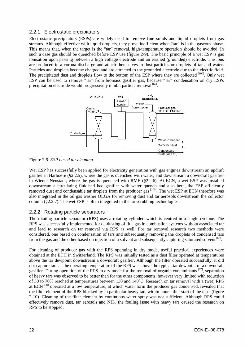
2.2.1 Electrostatic precipitators Electrostatic precipitators (ESPs) are widely used to remove fine solids and liquid droplets from gas streams. Although effective with liquid droplets, they prove inefficient when “tar” is in the gaseous phase. This means that, when the target is the “tar” removal, high-temperature operation should be avoided. In such a case gas should be quenched before ESP use (figure 2-9). The basic principle of a wet ESP is gas ionisation upon passing between a high voltage electrode and an earthed (grounded) electrode. The ions are produced in a corona discharge and attach themselves to dust particles or droplets of tar and water. Particles and droplets become charged and are attracted to the grounded electrode due to the electric field. The precipitated dust and droplets flow to the bottom of the ESP where they are collected [100]. Only wet ESP can be used to remove “tar” from biomass gasifier gas, because “tar” condensation on dry ESPs precipitation electrode would progressively inhibit particle removal [65].
Figure 2-9 ESP based tar cleaning Wet ESP has successfully been applied for electricity generation with gas engines downstream an updraft gasifier in Harboøre (§2.2.5), where the gas is quenched with water, and downstream a downdraft gasifier in Wiener Neustadt, where the gas is quenched with RME (§2.2.6). At ECN, a wet ESP was installed downstream a circulating fluidised bed gasifier with water quench and also here, the ESP efficiently removed dust and condensable tar droplets from the producer gas [100]. The wet ESP at ECN therefore was also integrated in the oil gas washer OLGA for removing dust and tar aerosols downstream the collector column (§2.2.7). The wet ESP is often integrated in the tar scrubbing technologies.
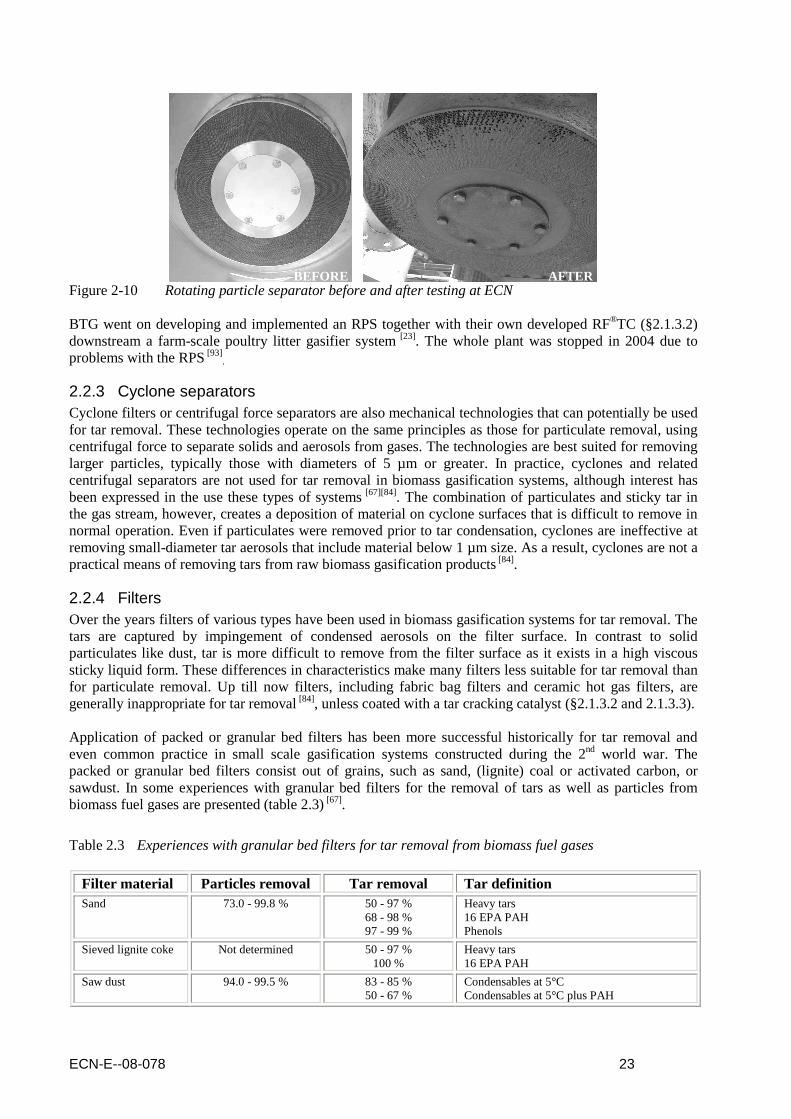
2.2.2 Rotating particle separators The rotating particle separator (RPS) uses a rotating cylinder, which is centred in a single cyclone. The RPS was successfully implemented for de-dusting of flue gas in combustion systems without associated tar and lead to research on tar removal via RPS as well. For tar removal research two methods were considered, one based on condensation of tars and subsequently removing the droplets of condensed tars from the gas and the other based on injection of a solvent and subsequently capturing saturated solvent [67]. For cleaning of producer gas with the RPS operating in dry mode, useful practical experiences were obtained at the ETH in Switzerland. The RPS was initially tested as a dust filter operated at temperatures above the tar dewpoint downstream a downdraft gasifier. Although the filter operated successfully, it did not capture tars as the operating temperature of the RPS was above the typical tar dewpoint of a downdraft gasifier. During operation of the RPS in dry mode for the removal of organic contaminants [67], separation of heavy tars was observed to be better than for the other components, however very limited with reduction of 30 to 70% reached at temperatures between 130 and 140°C. Research on tar removal with a (wet) RPS at ECN [98] operated at a low temperature, at which water form the producer gas condensed, revealed that the filter element of the RPS blocked by in particular heavy tars within hours after start of the tests (figure 2-10). Cleaning of the filter element by continuous water spray was not sufficient. Although RPS could effectively remove dust, tar aerosols and NH3, the fouling issue with heavy tars caused the research on RPS to be stopped.
ECN-E--08-078 23
Figure 2-10 Rotating particle separator before and after testing at ECN BTG went on developing and implemented an RPS together with their own developed RF®TC (§2.1.3.2) downstream a farm-scale poultry litter gasifier system [23]. The whole plant was stopped in 2004 due to problems with the RPS [93]
.
2.2.3 Cyclone separators Cyclone filters or centrifugal force separators are also mechanical technologies that can potentially be used for tar removal. These technologies operate on the same principles as those for particulate removal, using centrifugal force to separate solids and aerosols from gases. The technologies are best suited for removing larger particles, typically those with diameters of 5 µm or greater. In practice, cyclones and related centrifugal separators are not used for tar removal in biomass gasification systems, although interest has been expressed in the use these types of systems [67][84]. The combination of particulates and sticky tar in the gas stream, however, creates a deposition of material on cyclone surfaces that is difficult to remove in normal operation. Even if particulates were removed prior to tar condensation, cyclones are ineffective at removing small-diameter tar aerosols that include material below 1 µm size. As a result, cyclones are not a practical means of removing tars from raw biomass gasification products [84].
2.2.4 Filters Over the years filters of various types have been used in biomass gasification systems for tar removal. The tars are captured by impingement of condensed aerosols on the filter surface. In contrast to solid particulates like dust, tar is more difficult to remove from the filter surface as it exists in a high viscous sticky liquid form. These differences in characteristics make many filters less suitable for tar removal than for particulate removal. Up till now filters, including fabric bag filters and ceramic hot gas filters, are generally inappropriate for tar removal [84], unless coated with a tar cracking catalyst (§2.1.3.2 and 2.1.3.3). Application of packed or granular bed filters has been more successful historically for tar removal and even common practice in small scale gasification systems constructed during the 2nd world war. The packed or granular bed filters consist out of grains, such as sand, (lignite) coal or activated carbon, or sawdust. In some experiences with granular bed filters for the removal of tars as well as particles from biomass fuel gases are presented (table 2.3) [67].
Table 2.3 Experiences with granular bed filters for tar removal from biomass fuel gases
Filter material Particles removal Tar removal Tar definition Sand 73.0 - 99.8 % 50 - 97 %
68 - 98 % 97 - 99 %
Heavy tars 16 EPA PAH Phenols
Sieved lignite coke Not determined 50 - 97 % 100 %
Heavy tars 16 EPA PAH
Saw dust 94.0 - 99.5 % 83 - 85 % 50 - 67 %
Condensables at 5°C Condensables at 5°C plus PAH
BEFORE
AFTER

24 ECN-E--08-078
While packed or granular bed filters provide adequate filtration of tars, they still create operational problems related to cleaning the filter as well as to waste disposal. These filters may be appropriate for small systems operating in remote locations where labour is inexpensive, but they are not being incorporated into designs for larger-scale commercial facilities due to operational and cost considerations, unless as final guard bed [84].
2.2.5 Water scrubber A water based scrubber tar removal technology has been in operation since 2000 at the Harboøre updraft gasification plant in Denmark, operating on wood chips [89]. The technology has also been licensed to the Japanese company JFE and the German company Relax Umwelttechnik®. The producer gas from the reactor contains about 80 g/mn³ of various tars and acids. The gas temperature downstream the reactor is about 75°C. The producer gas is cooled serially through two district heating shell and tube heat exchangers in which a large amount of tar and water is separated together with most of the particles. Following this the gas is cleaned for remaining water/tar aerosols and dust in a wet ESP (§2.2.1). After these processes the contents of tar and dust are both below 25 mg/mn³, and the gas is suitable for fuelling gas engines.
Figure 2-11 Process scheme of the Harboøre process with water based tar scrubber and wet ESP This water based scrubbing technology results in a huge amount of tar-contaminated water. At the Harboøre plant every 1 kg of wood chips gasified results in approximately 0.6 kg of waste water [89]
. This water is separated in a coalescer into (i) heavy (high molecular) tars having a net calorific value of about 27 MJ/kg (approximately 8% on a weight basis) and (ii) water contaminated with light (low molecular) tars and acids. The heavy tar is stored in a 150 m³ heated tank and part of this tar is used for district heating peak load firing in the oil/tar hot water boiler. The bulk water fraction can not be discharged because of its phenol, total organic carbon (TOC) and acid content and therefore cleaned in the tar water cleaning system (TARWATC). The TARWATC uses hot water from the engine exhaust boilers to evaporate the contaminated water and to separate the light tars (having a net calorific value about 14 MJ/kg). The slightly contaminated steam is heated in counter-flow with clean steam from the TARWATC reactor to a high temperature before entering the reactor. The temperature is further increased by burning part of the light tars inside the reactor. The clean steam is condensed in a district heating cooled condenser and fulfils the environmental regulations for discharge into municipal systems [89]. Although the water based scrubbing technology is capable of cleaning the gas sufficiently for some applications [89] and the Harboøre plant operated 8000 hours in 2006 [96], the scrubbing technology shifts the tar problem to (expensive) treatment of wastewater [19].

ECN-E--08-078 25
2.2.6 RME scrubber As an alternative to water based scrubbers oil wash can be applied as well. This has been done successfully downstream both the indirect gasification process in Güssing [47][48] and the downdraft gasifier in Wiener Neustadt, with the latter one having a wet ESP installed as well to capture tar aerosols (§2.2.6). Without an ESP installed, filters would be required for removing these aerosols before the gas can be applied in the gas engines.
Figure 2-12 Process scheme of the FICFB process with RME based tar scrubber The tar is almost completely removed by the scrubber using rapeseed oil methyl esther (RME) as a medium. After phase-separation of the condensate, the RME saturated with tar is recycled to the combustor of the indirect gasifier, which means that no liquid waste stream is produced. In order to be able to apply RME as scrubbing liquid, though, the initial tar concentration in the producer gas has to be relatively low, as otherwise the required amount of RME would be too large. At the Güssing plant, the tar concentration of the producer gas therefore is reduced to approximately 2.5 g/mn³ by using olivine as catalytic bed material [48]. Furthermore, the RME contributes significantly to the total ecological impact of the gasification process [41]. Application of the oil based OLGA tar removal technology (§2.2.7) instead of the RME scrubbing technology reduces this negative effect of scrubbing liquid consumption, as hardly any oil is consumed during operation.
2.2.7 OLGA The oil gas washing technology OLGA developed by ECN and Dahlman [47][59] is based on a multiple stage scrubber in which the producer gas is cleaned by special scrubbing oil. In the first section of OLGA (the collector, figure 2-13) the gas is gently cooled down by the scrubbing oil. Heavy tars condense and are collected, after which they are separated from the scrubbing oil and can be recycled to the gasifier in order to serve as feedstock of the gasifier. As only tars are recycled to the gasifier, the amount of scrubbing liquid used is not limited like in the RME scrubbing technology (§2.2.6) and hence higher tar loads in the producer gas are acceptable. In the second stage of OLGA (the absorber / stripper), lighter gaseous tars are absorbed by the scrubbing oil. The tar-laden oil is regenerated in a stripper. In case of an air or steam blown gasifier hot air is used to strip the tars off the scrubbing oil. This air loaded with light tars can be used as the gasifying medium in the gasifier. Hence, the stripper column design is not only based on the tar removal capacity but also on the amount of air that can be used by the gasifier. All heavy and light tars can be recycled to the gasifier where they are destructed and contribute to the energy efficiency [73]. Tar waste streams are efficiently recycled this way [59]. The OLGA technology has been demonstrated downstream different gasifiers operated on a variety of fuels at ECN and in Moissannes, France [v]. Dahlman is realising an OLGA tar removal system for a gasification plant which will use 1 tonne per hour of chicken litter and/or forest residues as feedstock. At this moment, the plant is in the engineering phase. It is scheduled to be started in the autumn of 2009. Furthermore, Biomass Gas & Electric, SilvaGas, Dahlman and Solar announced that they are working towards the realization of an advanced biomass gasification plant, scheduled for completion in 2010 [v].
v The gasifiers at ECN include CFB, BFB and indirect gasification processes, whereas the plant in Moissannes is based on a special updraft gasifier [59]. Feedstocks used for testing include wood, grape pulp and more recently fluff. More information can be obtained from the Dahlman OLGA technology website www.olgatechnology.com.

26 ECN-E--08-078
Heavy tars & Fine Particulates
C oarse particulatesash / soot
Light tars in air or steam
Air or Steam
Cyclone
Clean gasCollector
WetESP
AbsorberStrippe r
Raw gas
Figure 2-13 Process scheme of the OLGA tar removal technology ECN operated and tested two aqueous systems and one oil based system, OLGA, downstream their 500 kWth air blown circulating fluidized bed gasifier, producing a producer gas with an initial tar load of 10 to 20 g/mn³ on dry basis [v]. In figure 2-14 the tar removal efficiency of the three tested gas cleaning systems is compared [59].
Figure 2-14 Comparison of scrubbing based tar removal technologies In the aqueous scrubber the gas was not on specification for a gas engine. With the addition of a wet ESP the heavy tars were almost completely removed and the tar dew point decreased to 60°C. The producer gas could be applied in a gas engine, but the system suffered from wastewater problems. The OLGA removed the tars almost completely. The tar dew point was reduced well below a temperature of 10°C. The water condensate did not contain phenols and the gas could be applied in a gas engine.

ECN-E--08-078 27
3. Non-tar components
Whereas tar formation is mainly caused by the operating conditions of the gasifier and less by the composition of the biomass feedstock, for non-tar components the situation is reversed. The elemental composition of the feedstock therefore determines the basic requirements for gas cleaning downstream the gasifier.. Table 3.1 shows an indicative composition of several biomass feedstocks taken from the Phyllis database [vi][99], and shows for example that for non-woody biomass, chlorine, sulfur and ash fractions are much higher than for woody biomass. The use of such fuels will therefore most likely require additional gas cleaning measures to overcome either emission problems, corrosion issues or contamination of downstream processes (i.e. catalyst deactivation, oil degradation, …).
Table 3.1 Composition of several biomass feedstocks
C (wt%daf)
H (wt%daf)
O (wt%daf)
N (wt%daf)
S (wt%daf)
Cl (wt%daf)
Ash (wt%db)
H2O (wt%ar)
Untreated wood 48,8 6,0 44,6 0,4 0,03 0,02 1,6 12,8
Treated wood 50,7 6,1 41,7 1,2 0,11 0,08 2,7 17,8
• Demolition 49,4 5,9 43,1 0,9 0,08 0,05 4,3 18,9
• Impregnated 52,5 6,2 40,4 0,6 0,17 0,11 1,5 23,5
• Particle board 50,1 6,2 41,6 2,2 0,08 0,08 2,3 11,1
Grass 49,2 6,0 43,5 0,9 0,16 0,38 3,6 15,4
Straw 50,5 6,1 41,3 1,1 0,15 0,48 10,9 6,1
Manure 51,8 6,4 34,2 4,4 0,85 1,41 32,9 45,7
• Poultry 48,2 5,6 34,8 6,2 0,74 0,73 19,6 30,1
• Cow 53,1 6,8 34,9 2,6 0,95 1,66 43,7 14,9
• Pig 54,1 6,8 33,0 4,3 - 1,84 35,4 92,1
Sludge 50,2 7,2 39,7 2,9 1,00 0,30 25,3 25,3
• Food industry 52,8 8,1 39,9 1,0 0,77 0,01 9,3 7,8
• Paper 49,2 6,0 43,1 1,1 0,45 0,43 33,3 36,8
• Sewage 48,5 7,5 36,2 6,7 1,87 0,53 33,4 31,2
Refuse Derived Fuel 51,8 7,2 39,3 1,1 0,40 0,39 15,0 25,0
Municipal Solid Waste 56,0 5,1 26,6 1,2 0,50 1,13 39,6 34,8
In this chapter, the different gas cleaning technologies for non-tar components are discussed. Also included is a paragraph on unsaturated hydrocarbons still present in the producer gas after tar removal, as these components have a significant influence on downstream synthesis processes, for example on methanation towards Substitute Natural Gas (SNG) [20].
3.1 Chlorine Chlorine compounds are present in most biomass feedstocks, though sometimes chlorine concentrations are extremely low (table 3.1). When present in combination with ammonia, it can form ammonium chloride (NH4Cl), which at high temperatures is in the vapour phase, but below 250-280°C becomes solid and presents a fouling risk for downstream process steps. When dissolved in (condensed) water it becomes highly corrosive. Similar problems occur in combination with metals present in the feedstock, e.g. potassium and sodium. Although not part of the gas cleaning, it is mentioned that chlorine can play a significant role in bed agglomeration issues and that its concentration in the producer gas increases with increasing temperatures of gasification [20].
vi The Phyllis database: www.phyllis.nl
28 ECN-E--08-078
3.1.1 HCl HCl removal processes can be categorised in two groups: dry and wet processes [20]. In the dry process, the chlorine is removed with an adsorbent, in the wet process with a scrubbing liquid. For dry removal of HCl, two types of adsorbents are commercially available, i.e. sodium carbonate (Na2CO3, NaHCO3) and calcium oxide (CaO) [56]. For the cleaning of producer gas, CaO is less suitable as it reacts with CO2. The CO2 does not influence the performance of Na-sorbents when applied in the temperature range of 300 to 600°C. The optimum temperature for the reaction was found to be between 400 and 500°C [40], at which HCl concentrations in the producer gas can be reduced to below 1 ppmv [99]. The wet scrubbing process is usually based on either water or a caustic water solution. The amount of water normally present in the producer gas should be able to remove 500 ppmv of HCl from the gas when condensing. If it is not allowed to dispose the condensate onto surface water, additional water treatment (e.g. an ionic exchanger) has to be implemented, which could make the cleaning system rather expensive
[99]. The alternative would be to use a caustic scrubber. This will not only remove HCl effectively, but also other components present in the producer gas like CO2, COS and H2S
[58]. The products formed are all stable salts: HCl + NaOH � NaCl + H2O (eq. 1) CO2 + 2NaOH � Na2CO3 + H2O (eq. 2) H2S + NaOH � NaHS + H2O (eq. 3) H2S + 2NaOH � Na2S + 2H2O (eq. 4) COS + 2NaOH � Na2S + H2CO3 (eq. 5) The reaction with CO2 should be avoided, as the formed carbonate salt has a low solubility. By having limited residence times, this reaction is avoided. The reactions between NaOH and HCl as well as H2S occur relatively fast; hence it is possible to achieve a high selectivity towards HCl and H2S while limiting the CO2 removal from the producer gas [58]. For CO2 removal a more optimal removal technology may be applied.
3.1.2 Dioxins and furans Dioxins and furans are emitted in all thermal processes, where the combination of an inadequate process temperature (<850°C), the presence of chlorine as well as insufficient concentration of oxygen and residence time (<2s) allows aromatics to form and/or survive [99]. Dioxins, or officially polychlorinated dibenzodioxins (PCDD, figure 3-1), are a group of poly-halogenated compounds which are significant because they act as highly toxic environmental pollutants.
Figure 3-1 General structure of polychlorinated dibenzodioxins (PCDD) Dioxins can be removed from gases through absorption/adsorption in a polymer material. The ADIOX® technology developed by the Forschungszentrum Karlsruhe and Götaverken Miljö uses polypropylene (PP) doped with carbon particles. The process is based on the high affinity of dioxins to carbon - when in contact, the bond between dioxins and carbon is very strong. By dispersing small particles of carbon in PP a dioxin molecule present in the flue gas is first absorbed into the PP, where it migrates to a carbon particle, on which it is very strongly adsorbed (connected to its surface). The plastic material acts as a selective filter with a preference for molecules like dioxin [44]. An alternative for the removal of dioxins is the oil based scrubbing technology OLGA, as discussed in §2.2.7. Duration tests with OLGA for the fuel cell and gas engine application revealed that dioxins were removed together with tars to a sufficiently low level (below 0.1 ng/m³) [99]. Considering the general structure of dioxins (figure 3-1) this does not come as a surprise. The OLGA is designed for cleaning the producer gas, however might be applied for cleaning dioxins from gases as well.

ECN-E--08-078 29
A third alternative for the technology based on carbon adsorption is catalytic destruction of dioxin compounds. For flue gases, this is a commercially available technology. The CRI system for example uses a specially developed catalyst to convert dioxins in the presence of oxygen to a mixture of H2O, CO2 and HCl. The specific CRI dioxin destruction catalyst operates at temperatures around 160° C [vii] . Dioxin removal straight from the producer gas (with no oxygen present) is not possible with this catalyst.
3.2 Sulfur
The sulfur in the biomass is mainly released as H2S and COS, and only in small amounts as organic sulfur (mercaptanes and thiophenes). The operating temperature of the gasifier mainly determines the exact ratio between the sulfur components [99]. The organic components, in particular mercaptanes, are unstable at high temperatures, however presence of organic sulfur should not be forgotten as it results in issues in downstream processes (emissions, catalyst deactivation) and often is not removed by conventional H2S and COS removal technologies. Table 3.2 provides an overview of the pros and cons of different sulfur removal processes. In paragraphs §3.2.1 to 3.2.3 these are discussed in more detail.
Table 3.2 Pros and cons of sulphur removal processes
Technology Pros Cons Effect on organic S Effect on CO2 Dry sorption / reaction
Limited effect of pressure, wide variety of absorbens available
Waste production, regeneration results in sulphur rich waste gas
Also effective for thiol compounds, unsure for thiophenes
High H2S selectivity
Physical absorption
Commonly used, solvent regenerable, removes HCN and Hg
High pressures required, removes HC as well, high OPEX
Removes all organic sulphur compounds
Removes also CO2
Absorption in alkali solution
Relatively simple, commonly used
Corrosion, high heat consumption for regeneration
Partially effective with amines, with K2CO3 only traces
High H2S selectivity, amines however also remove CO2
Liquid oxidation
Results in elementary sulphur
Large equipment, low quality sulphur
Also effective for thiols, not for COS
High H2S selectivity
Adsorption Regeneration results in sulphur rich waste gas
Also effective for some organic sulphur compounds
High H2S selectivity, can however also remove CO2
Biological removal
Mild conditions, limited CAPEX
Functionality unsure for HC containing gas
Unknown High H2S selectivity
3.2.1 H2S The removal of H2S is often coupled to CO2 removal. Kohl [58] gives general guidelines for a preliminary screening for a H2S and CO2 removal process, grouping the H2S removal processes into six types. Table 3.3 gives the list and also suggests the preferred areas of application for each process type. This is particular of interest as conventional H2S removal technologies might be less interesting for H2S removal from biomass based producer gases due to the relatively small amount of H2S present.
Table 3.3 Guideline for H2S removal processes
Plant size Partial pressure Sulfur removal capacity Absorption in alkali solution > 25,000 mn³/h < 7 bara > 10 ton/day
Physical absorption > 25,000 mn³/h > 7 bara > 10 ton/day
Liquid oxidation > 25,000 mn³/h < 7 bara < 10 ton/day
Dry sorption / reaction < 25,000 mn³/h < 7 bara < 10 ton/day
Adsorption < 25,000 mn³/h < 7 bara < 10 ton/day
Membrane permeation < 25,000 mn³/h > 7 bara < 10 ton/day
vii CRI catalysts: www.cricatalyst.com

30 ECN-E--08-078
Both absorption in an alkaline solution (chemisorption by e. g. aqueous diethanolamine, NaOH solution) and in a physical sorbent (e.g. poly ethylene glycol) are suitable for treating high-volume gas streams containing H2S and/or CO2 to below 1 ppmv. However, physical absorption processes are not economically competitive when the partial pressure is low as the capacity of physical solvents is a strong function of partial pressure [99]. The boundary line between physical and chemical solvents is approximately 7 bara [90]. Solid sorption is applicable to low quantities of H2S. Suitable adsorbents are oxides of Fe (~1 ppmv), Mn (~5), Zn (<0.3), Cu (<1) and Ca (~50), with the final H2S concentration achievable reported between brackets. Operating temperatures are between 350 and 500°C, except for Ca and Mn (up to 1000°C). Most sorbents cannot be regenerated and must be disposed after being used, although regenerative processes are under development. Adsorption with molecular sieves is a viable option when the amount of sulfur is very low and the gas contains heavier S compounds (such as mercaptane and COS) that must also be removed
[99]. The effect on thiophenes, however, is limited. Membrane permeation involves the separation of individual compounds on the basis of the difference in their rates of permeation through a thin membrane barrier. In general membranes for H2S removal (< 1ppmv) are applied for small-scale plants with gases containing a high H2S concentration. The capacity is accomplished by using proportionately increasing number of modules. Therefore, the process does not realize the economy of scale and becomes economically less competitive with absorption processes as the plant size is increased [99]. In general H2S can be recovered as elemental sulfur, S, by using a biological process or by the reaction with SOx
[99]. The standard technology for recovery of concentrated H2S to elemental sulfur is the Claus process. Normally this process is operated parallel to physical or chemical absorption/desorption process like the Rectisol process or alkanol amine processes. The Rectisol or alkaline amine process removes the H2S from a diluted gas stream. The gas from the desorption step is concentrated with H2S and can be applied in the Claus process for the conversion of H2S to elemental sulfur. In general the Claus process will be too expensive on the small scales associated to biomass applications. Even for large scale biomass gasification facilities the amounts of sulfur are limited, unless typical feedstocks like MSW, RDF, manure or sludge are applied. Alternatively to the Claus process, H2S can be easily and economically converted to elemental sulfur by biological processes, using microorganism to convert S2- to elemental S. The H2S can be removed in an alkaline scrubber from the gas. The chemically absorbed H2S can consequently be fed to the biological reactor where the H2S in the solution is converted into elemental sulfur with the bacteria present in the reactor. The THIOPAQ process by Paques [viii] is an example of such a biological process.
3.2.2 COS Carbonyl sulphide (COS) is an organic sulfur compound, that can not be removed efficiently by physical or chemical removal processes. Thermodynamically, COS will shift towards formation of H2S though as the gas is cooled down to a low temperature. At a gas temperature of 200 °C, thermodynamically there is no COS present. This implies that it is possible to convert COS to H2S. Catalysts applied for this conversion include activated alumina, titania on alumina and Mo/Co catalyst. The ZnS product from the absorption of H2S with ZnO also catalyzes the COS conversion via the hydrogenation reaction. So, when the ZnO bed contains ZnS, COS can be converted into H2S, which is, subsequently, adsorbed by the ZnO. As such, an upstream catalyst for the removal of COS would not be necessary [99].
3.2.3 Other organic sulphur compounds The principal organic sulfur compounds that are present in the producer gas are carbonyl sulfide (COS, §3.2.2), carbon disulfide (CS2), mercaptans (RSH), thiols (CH4S, C2H5SH), thiophenols (C6H6S), and thiophenes (aromatic sulfur, e.g. C4H4S). The organic sulfur compounds are much less acidic than hydrogen sulfide (H2S) and are therefore not effectively removed by conventional alkaline solution based H2S removal technologies. Physical solvents, however, generally show a very high solubility for organic
viii The THIOPAQ process by Paques: www.paques.nl

ECN-E--08-078 31
sulfur compounds [58]. The absorbed organic sulfur compounds end up in the separated acid gas stream. Although effective for contaminant removal, these physical solvents often also remove considerable amounts of valuable hydrocarbons, among which also (small) amounts of CH4. As such, they are often not preferred. For high-efficient processes, e.g. the synthesis of ammonia, substitute natural gas, methanol, and other chemicals, catalytic conversion of the organic sulfur compounds is more interesting [58]. In catalytic conversion, the organic sulfur is hydrodesulfurized upstream the H2S removal into H2S via either hydrogenation (e.g. equation 1 to 4) or hydrolysis (e.g. equation 5 and 6): CS2 + 2H2 � C + H2S (eq. 1) COS + H2 � CO + H2S (eq. 2) RCH2SH + H2 � RCH3 + H2S (eq. 3) C4H4S + 4H2 � C4H10 + H2S (eq. 4)
CS2 + 2H2O � CO2 + 2H2S (eq. 5)
COS + H2O � CO2 + H2S (eq. 6)
The first hydrogenation reaction (equation 1) demonstrates the risk of carbon formation. The first catalysts used commercially for hydrodesulfurisation at the beginning of 1900 were based on nickel sulfide catalysts, followed in the mid 1900’s by copper, iron, zinc, cobalt, or nickel thiomolybdates. All were operated at temperatures between 300 and 450°C. Due to the deposition of carbon the catalysts have to be regenerated on a regular basis [58]. Nowadays, most hydrodesulfurisation (HDS) catalysts are based on cobalt and nickel and molybdenum oxides on an active (possibly titanium enhanced) alumina base (Al-Co-Mo and Al-Ni-Mo). These catalysts are effective at decreased volumes of catalyst charges as well as at sudden change of sulfur content and are operated at temperatures between 250 and 400°C and at elevated pressure (up to 40 bar). Prior to use, the oxidised catalyst has to be sulfided [58], as the active phase in the operating catalyst is the Co-Mo-S or Ni-Mo-S phase. This sulfidation will normally take place by exposing the catalyst as delivered to the normal operating conditions in the plant, i.e. the sulfur for sulfidation is supplied by the feed and at the concentration at which it is available [85]. The CoMo and NiMo catalysts are mainly developed for fossil based technologies and are commercially available from the leading catalyst suppliers such as Haldor Topsøe, Süd Chemie and Johnson Matthey. Application of these catalysts for biomass based processes, as done by ECN [20][74][104][105] and PSI [14][15][16] in their SNG development, might cause some issues concerning the sulfur and olefins concentrations in the producer gas and the relatively low operating pressures. If the sulfur content in the feed is constant and low, the stable sulfur concentration in the catalyst and thus the activity will be low. Although normally not problematic, the catalyst may not convert organic sulfur sufficiently during a short period if the concentration suddenly increases. The catalyst will have to be fully sulfided before the slip of organic sulfur will go down again [85]. If the olefins are hydrogenated as well, this exothermic reaction will cause a significant temperature increase over the HDS reactor. As such, it might be necessary to lower the inlet temperature of the HDS reactor; however this will have a negative effect on the HDS of the organic sulfur compounds [58]. The low operating pressures compared to the normal operating conditions for which the HDS catalysts are designed (10 and 40 bar) also has a significant influence on the HDS catalyst activity. Experiments with a Ni-Mo/SiO2 catalyst at different temperatures and partial pressures showed a significant effect of both parameters on the catalytic activity, as is illustrated in figure 3-2 [21][106].

32 ECN-E--08-078
Figure 3-2 Catalytic activity for thiophene HDS versus thiophene (partial) pressure
3.3 Nitrogen
Nitrogen present in the producer gas originates either from the feedstock (typically ending up in the form of HCN and NH3, partially as pyridine, in the producer gas) or from the gasifying agent (in the form of N2 in case of air-blown gasification, HCN and NH3 resulting from molecular nitrogen can be neglected) [47]. Compared to coal based gasification, the HCN concentrations in the biomass producer gas are roughly the same (~20 ppmv), the NH3 concentration, however, can be significantly higher (up to thousands of ppmv compared to up to 40 ppmv for coal) [17][47]. The presence of NH3 as well as chlorine in the producer gas might result in the formation of NH4Cl, a chemical that becomes solid below 250-280°C and presents a fouling risk [47]. Ammonia in the presence of H2S can result in formation of ammonium(poly)sulphide, which solidifies at temperatures below 150°C. HCN is reported to be a potential contributor to the deactivation of for example FT catalysts [17]. When hot producer gas is used to generate electricity in integrated gasification combined cycle (IGCC) power plants, both NH3 and HCN will partly be converted to nitrogen oxides (NOx) which are difficult to remove and are highly undesirable as atmospheric pollutants. Removal of NH3 and HCN is therefore often required. For NH3 removal either catalytic destruction or wet scrubbing can be applied. Catalytic destruction of NH3 is possible using catalysts similar to those used for tar cracking or hydrocarbon reforming. Dolomite, Ni-based steam reforming catalysts as well as Fe-based catalysts have all been reported to be able to convert NH3 at temperatures of approximately 900°C [63][64][83]. Using these catalysts, destruction of >99% of the NH3 is possible [84]. Although this combined tar and NH3 removal has the potential to remove both tars and NH3 from the producer gas while maintaining the heat of the producer gas, commercial tar cracking systems at this temperature are still under development (§2.1.3). Ammonia may also be removed from the producer gas by wet scrubbing. The main problem with wet scrubbing is the presence of tars in the producer gas, which end up in the water as well. At the Harboøre plant the tar and NH3 contaminated waste water is treated in the tar water cleaning system (TARWATC)
[76] (§2.2.5). More ideally tars and NH3 are removed separately in order to avoid contamination of the water with tars. However, this requires the removal of tar before the wet scrubber to such a level that the tar dew point is well below the operating temperature of the water scrubber, i.e. well below approximately 30°C. The oil scrubbing technology OLGA (§2.2.7) is capable of doing this and therefore allows downstream implementation of a “conventional” water scrubbing system [59]. The NH3 is soluble in water and can either be neutralised with acids to form ammonia salts, converted biologically into N2 or stripped from the scrubbing water.

ECN-E--08-078 33
In the latter case, the stripper air containing the NH3 can be recycled to the gasifier to be converted to N2 and H2O. This conversion requires a temperature above 800°C in order to reach over 50% conversion and is nearly complete (>90%) at 850°C [72]. The presence of oxygen or air at the injection point will lead to a much higher rate of NH3 destruction than observed for pure thermal cracking. Tests at ECN also revealed hardly any NH3 was converted to NOx. When applying a biological process to clean the scrubbing water, e.g. via the ANAMMOX® process, bacteria convert NH3 into N2 via a combination of nitrification and de-nitrification reactions (figure 3-3). In 2002 the first full-scale plant was started up in the Netherlands and at this moment four installations are operational [ix] .The process can be used for the removal of ammonium with a relatively high ammonium concentration (>100 mg/l), however the bacteria’s applied are sensitive for hydrocarbon pollution.
Figure 3-3 Biological ammonia removal
3.4 Carbon dioxide
Removal of CO2 from the producer gas may be necessary for various reasons. In combination with water, it is for example highly corrosive and rapidly destroys pipelines and equipment unless it is partially removed or exotic and expensive construction materials are used. Furthermore, for specific processes like methanol and FT diesel synthesis the inert CO2 present in the gas will require higher overall operating pressures. Within the framework of the EOS-LT consortium project “Biomass gasification and gas cleaning” though, the removal of CO2 is mainly done for the purpose of producing (substitute natural) gas with a high enough heating value to comply with the standards of the conventional application of the gas and (to a lesser extent) the purpose of carbon capture and storage (CCS). For CO2 removal a wide variety of technologies are commercially available, including conventional absorption processes, such as the BenfieldTM process based on hot potassium carbonate solutions and amine scrubbing processes based on formulated solvents (e.g. MEA, DEA, MDEA [x]). However, also cryogenic as well as adsorption processes (e.g. PSA, TSA [xi]) and membranes are commercially available. For a detailed description of all these CO2 removing technologies reference is made to the Gas purification handbook by Kohl and Nielsen [58]. In the status report at hand, the focus for CO2 removal is on upgrading the quality of the producer gas. This is comparable with the upgrading of biogas or landfill gas. Overviews of these existing upgrading technologies by André de Boer and Mathieu Dumont of SenterNovem [34][39] are included in chapter 4 of this status report. Possible issues when applying these conventional upgrading technologies in thermo-chemical systems are provided in chapter 4 as well.
ix The Paques ANAMMOX process: www.paques.nl x MEA = Mono Ethanol Amine; DEA = Di Ethanol Amine; MDEA = Methyl Di Ethanol Amine xi PSA = Pressure Swing Adsorption; TSA = Thermal Swing Adsorption

34 ECN-E--08-078
3.5 Unsaturated hydrocarbons
The existence of unsaturated hydrocarbons in the producer gas varies widely and does not only include tars for which the removal technologies are described in chapter 2 [xii] , but also light unsaturated hydrocarbons like acetylene (C2H2), ethylene (C2H4) and benzene (C6H6). Unlike tars, these components do not create a high fouling risk due to straight condensation. However, they can react with and deactivate synthesis catalysts through carbon deposition or form gummy polymers that subsequently can plug downstream equipment due to condensation. The removal of unsaturated hydrocarbons can be done via physical separation (e.g. amine scrubbing, though with regards to selectivity cryogenics or selective adsorption makes more sense). Selective catalytic hydrogenation is however usually the preferred technique [58]. Platinum or palladium based catalysts typically can be used for the hydrogenation of C2H2 and C2H4 at relatively low temperatures. The NiMo and CoMo catalysts applied for HDS (§3.2.3) also demonstrated hydrogenation activity for unsaturated hydrocarbons and are unlike the Pt or Pd catalysts not sensitive for sulfur deactivation. From the hydrocarbon composition before and after the HDS it is clear that the compounds are actually hydrogenated towards CH4 and C2H6, and not cracked into CO and H2
[20] .
Experiments at PSI, however, also reveal that even after HDS not all unsaturated hydrocarbons are removed from the gas [13]. The components still present (i.e. C3H6, as well as C6H6 and C7H8 not completely removed in the tar removal step [20]) cause a significant risk of soot formation on the methanation catalysts applied at ECN and PSI [13][20]. When using a fluid bed methanation process, this soot formation might not be problematic and the catalyst might continuously be regenerated. R&D on removal of these components via scrubbing, hydrogenation or reforming is ongoing [13][20][86] and is crucial for long-term operation of catalytic synthesis processes downstream tar producing gasifiers. Although conventional (amine or methanol based) scrubbing technology [xiii] can easily solve this specific problem, severe scrubbing of the producer gas is not considered to be economically attractive due to the efficiency penalty associated with it and the complexity of cleaning the scrubbing medium. Maintaining the hydrocarbons in the producer gas, either as (stable) saturated light hydrocarbons (i.e. CH4 or even better C2H6 and C3H8) or if necessary converted to synthesis intermediates (i.e. CO and H2), will result in significantly higher production efficiencies, and hence ultimately an economically more attractive process.
3.6 Particles and alkalis
The need for particulate and alkali removal significantly depends on the use of the producer gas. For gas engines, particulate levels must be reduced to below 50 mg/mn³, whereas for turbines (< 15 mg/mn³) and catalytic processes (<0.02 mg/mn³) the requirements are even more stringent [84]. These particulates do not only include char and ash present in the initial producer gas of the gasifier, but also alkalis. The mineral matter in biomass contains high levels of alkali salts, particularly e.g. grass, straw and other fast growing biomass, which contain large amounts of potassium. At temperatures of around 800°C, the alkali salts can vaporize and create problems by depositing on cooler surfaces downstream. The alkali will remain in the vapour phase until it condenses due to cooling below about 650°C, typically forming small particulates (<5 µm) or condensing straight on surrounding surfaces like other particulates or the process equipment. In gasification, alkali vapours are removed by cooling the hot producer gas below 600°C to allow for condensation of the material into solid particulates [84]. The solids are then removed using various dry or wet particle removal systems. These particle removal systems not only have to be designed taking into account the chemical behaviour of the condensed alkali salt, but also the effect of tar condensation (appendix A). As such, particle removal is normally closely linked to and installed together with some kind of tar removal technology, as became already clear in §2.1 and 2.2 of the status report at hand. In this paragraph, the main particle removal technologies are discussed briefly, emphasising in particular on the issues that occur when applying these “conventional” technologies in a tar loaded producer gas stream.
xii A well accepted definition states that tars are all organic compounds with a molecular weight higher than benzene. A better and more detailed tar description is given by the classification of tars as described in appendices A and B. xiii Process like the methanol based Rectisol® process or alkanol amine processes are known for their combined removal of sulphur, nitrogen and hydrocarbon contaminants however are hardly selective and require significant stripping and/or distillation to regenerate the scrubbing medium applied.

ECN-E--08-078 35
3.6.1 Cyclones In a cyclone, the particles containing producer gas is introduced tangentially into a cylinder. The gas exits the cyclone at the top while the particles, separated from the gas via centrifugal forces, slide along the wall of the cylinder to a dust collection chamber at the bottom of the cyclone (figure 3-4) [24]. Cyclones are particularly effective (>90%) at removing particles larger than a few micrometers with minimum pressure drop [84]. Smaller particles however are not caught.
Figure 3-4 The mechanical principle of a cyclone Cyclones are commonly used, also in biomass gasification systems, and are commercially available from many vendors. Typically they are operated at high temperature to avoid condensation of tars in the cyclone and often they are used as multiple units in series. A circulating fluidised bed gasifier will in general have an initial cyclone operated at the temperature of the gasifier, in which the bulk of unconverted char and ash is separated from the producer gas in order to be circulated to the bottom of the gasifier. Downstream this cyclone, multiple (colder) cyclones can be placed to collect particles with different sizes as well. The positioning of a cyclone in a gasification system can determine the success of the system. Due to the particle vortex it is possible to operate a cyclone at temperatures (slightly) below the tar dewpoint; the particles can remove some condensed tars from the walls as long as condensation is not too significant. Without the presence of these particles, the cyclone will not be cleaned. For this reason it is also recommended not to position a (final) cyclone upstream gas coolers, as in that case no particles are present capable of removing tars in the difficult producer gas cooling step as well.
3.6.2 Barrier filters Barrier filters are based on porous materials (e.g. metal or ceramic candles, bag filters, packed bed filters) that allow gases to pass, while blocking the particles (figure 3-4). They effectively remove small-diameter particulates in the range of 0.5 to 100 µm. Removal of smaller particles is also possible though associated with high pressure drops over the filters. The particles can be removed from the filter material by periodically pulsing clean gas through the filter in the reverse direction of normal gas flow [24]. To reduce the overall particulate load, these filters are typically placed downstream cyclones.
Figure 3-5 The mechanical principle of a barrier filter

36 ECN-E--08-078
Although barrier filters are effective for removing dry particulates, they are less suitable for wet or sticky contaminants such as tars. Tars cling to the filter surface and can undergo subsequent carbonization reactions that lead to fouling and plugging [24]. Hence, in biomass producer gases, these barrier filters are applied either in gases where tars are already significantly removed (e.g. at Güssing, §2.1.3.1 and Skive, §2.1.3.2) or operated at high temperature, above the dewpoint of tar. These high temperature gas filters (HGF) were tested at the commercial demonstration facility at Värnamo, Sweden [88] and more recently at the pilot facility at ECN [101]. At both sites, the filters were operated at 350 to 400°C, hence above the tar dewpoint. At Värnamo, the ceramic candle elements broke repeatedly due to the frequent thermal cycling in the demonstration facility that operated intermittently [24]. This has been solved by using metal fibre filters. The tests at ECN were not successful. Fouling of the HGF upstream the OLGA tar removal led to a serious increase of the pressure drop over the HGF (Figure 3-6). The HGF upstream the OLGA system was successfully replaced by an electrostatic precipitator within OLGA (§2.2.7).
Figure 3-6 Temperature (blue line) and pressure drop (pink line) of the hot gas filter at ECN HGF research now mainly focuses on the combined ceramic gas filtration and catalytic tar cracking [45] as being developed by Pall (Schumacher) and Madison Filter (in cooperation with Haldor Topsøe) as discussed in §2.1.3.3. These filters operate at temperatures of around 750 to 900°C, and as a result are relatively large and expensive units. Operation of barrier filters at lower temperatures however often resulted in tar fouling, hence making the filters only applicable downstream some kind of tar removal unit or downstream gasifiers with an initially low tar dewpoint.
3.6.3 Electrostatic filters / scrubbing technology Electrostatic filters are based on separating charged particles in an electrostatic field. The particles are collected on so called plate curtains (figure 3-7), where the formed particle layer is removed via dry or wet methods [24]. The dry methods are based on mechanical cleaning of the surface area and can operate at high temperatures (up to 500°C), whereas in wet methods the particle layer is removed with a thin film of flowing liquid, usually water. As such the wet ESP has a typical operating temperature below 100°C, or at least below the condensation temperature of the liquid applied. With the ESP being relatively expensive on a small scale, the technology is attractive only for large-scale operation [84].

ECN-E--08-078 37
Figure 3-7 The mechanical principle of an electrostatic filter As good charging of particles would require a minimal particle size of 0.5 µm, an ESP is in general less efficient for small particles. Often though, ESP systems are applied downstream a cooling and scrubbing system, in which small particles present in the gas (e.g. ash, aerosols) grow in particle size due to condensation of a liquid on the particle, being either water, RME or oil. As such, an ESP becomes suitable as well for small particles and hence very high separation efficiencies can be obtained. The ESP has been applied successfully in several biomass gasification systems and has therefore become a commercially proven and available technology for thermal biomass conversion systems as well. The issues with tar are dealt with by having a scrubber installed upstream the ESP. At Harboøre (§2.2.5), the particles (including tar aerosols) grow by condensation of water on the particle and as such are separated in a water based wet ESP. In the RME (§2.2.6) as well as the oil based OLGA (§2.2.7) scrubbing technology the principle is the same, however in stead of water, RME or oil is used. As such, the (wet) ESP not only operates as a filter for particles (e.g. ash, dust, alkalis), but also as a tar aerosol filter.

38 ECN-E--08-078
ECN-E--08-078 39
4. Biogas upgrading technologies
Although upgrading of biogas or landfill gas is not considered to be a R&D topic within the EOS research area “gasification, gas cleaning, conditioning and syngas production”, an overview of these existing upgrading technologies by André de Boer of SenterNovem [34] is included in this chapter, and formed the basis of a leaflet by Mathieu Dumont of SenterNovem [39]. The technologies in this sector may also apply for gas obtained from thermo-chemical conversion processes, in particular when aiming for the production of SNG. Due to the differences between thermo-chemical and bio-chemical processes, some comments on possible issues when applying these conventional upgrading technologies in thermo-chemical systems are included at the end of this chapter.
4.1 Conventional upgrading technologies The new trend in biogas production is the upgrading of the biogas to natural gas quality and injecting this upgraded biogas in the natural gas distribution grid. Five existing upgrading technologies currently exist on a commercial basis. This memo tries to provide a comparative overview of these five technologies. Vacuum Pressure Swing Adsorption This batch-wise operated process uses activated carbon molecular sieves to filter the pressurised biogas. The sieves mainly adsorb CO2, while letting the CH4 pass. The coal is regenerated by lowing the pressure to levels well below 1 bara. In these vacuum conditions the CO2 is released and the carbon can be used again for CO2 adsorbtion at elevated pressure. Membranes In this continues process compressed biogas flows through a membrane with high selectivity for CO2 and low selectivity for CH4. As a result, two gas streams are obtained, one containing the CO2 and the other the CH4. Due to limitations in the membrane selectivity both streams are slightly contaminated by the other component. Water wash In this continues process, the biogas flows though circulated cold water, dissolving hardly any CH4 though significant amounts of CO2. The remaining gas however still contains some CO2. The CO2 is removed from the saturated water at elevated temperatures. After re-cooling, the water can be used again. LP Cooab This continues low-pressure CO2 absorption process operates in a similar way as the water wash process. In stead of water, an amine solution is used though with higher CO2 and lower CH4 absorption performance. As a result, the separation of CO2 from CH4 is significantly improved. Cryogenic This process can be operated both batch-wise and continuously. The biogas is cooled to temperatures at which the CO2 becomes liquid, while the CH4 is still present in a gaseous phase. The easily separated CO2 is sold either as liquid or re-vaporised after which it might be injected in CO2 grids. For biogas upgrading technologies, the following parameters play a crucial role:
� Electric efficiency: The electric efficiency is mainly influenced by the required compression steps (if applicable). A smart design can reduce the overall electricity consumption of compression and decompression significantly.
� Thermal efficiency: The thermal efficiency is mainly influenced by the required heat for the recovery of the absorbent or the adsorbent and the heating after adiabatic expansion.

40 ECN-E--08-078
� Energetic efficiency: The energetic efficiency is a combination of both electric and thermal efficiency, and is based on the assumption that the required process energy is generated by the initial biogas.
� Methane slip: CH4 is inevitably partially removed from the biogas as well together with the undesired components like CO2. This GHG CH4 hence ends up in the waste gas stream or even worse is vented off. In the later case, the negative effect of methane slip might be limited by sending this gas to the air-inlet of a CHP plant (if applicable).
In table 4.1 some characteristics of conventional biogas upgrading technologies are listed. The figures presented are all base don upgrading 1 mn³ biogas with initial methane content of 65% and on injection of the upgraded biogas in a natural gas grid operated at 4bara.
Table 4.1 Characteristics of conventional biogas upgrading technologies
VPSA Membrane Water wash LP Cooab Cryogen Operating pressure [xiv] ~5 bar > 8 bar > 8 bar ~ 8 bar 10-18 bar [39]
Energy consumption
- electric (kWhe) [xv] 0.25 0.14 0.40 0.12 ~0.22
- thermal (kWth) [xvi] 0 0 0 0.4 0.04
- methane slip (%) 3% 18% 3% 0.1% Limited
Simplified efficiency [xvii]
- without heat recovery (%) 93 80 91 92 ~95
-with heat recovery (%) 93 96 91 98 ~96
Methane in final gas [39] max. 98% max. 90% max. 98% max. 99.5% max. 99.5%
4.2 Issues in relation to thermo-chemical systems
It has to be mentioned that possible issues exist when applying these conventional upgrading technologies in thermo-chemical systems. In general, the final SNG will have a similar composition compared to biogas, though the pressure level at the end is much higher due to the methanation at an elevated pressure. This will influence the presented figures significantly. For example, the low pressure LP Cooab process would make less sense, as the inlet pressure of this process is near atmospheric. Within the thermo-chemical SNG production the CO2 removal might however also be placed more upstream in the process, where pressure levels are still relatively low, even near atmospheric. This will also influence the presented figures significantly. In that case, the low pressure LP Cooab process would make more sense, as it is the only process benefitting from a low initial pressure. A final more general comment is that for most biogas plants, low value residual heat is not at hand, hence upgrading technologies with low thermal energy consumption might be preferred (i.e. VPSA, membranes and water washes). In a thermo-chemical SNG production process significant amounts of low value residual heat are available, hence upgrading technologies with high thermal energy consumption might be acceptable and the focus would be on reducing the electric energy consumption (i.e. LP Cooab).
xiv Highest pressure level reached within the system xv Electric energy as required from the grid, note that the primary energy requirement is 2.5 times the presented figure xvi Thermal energy as required, note that this can often be obtained from low value heat as it is associated with recovery of the absorbens (LP Cooab) or re-heating after severe cooling (cryogene) xviiRatio between the amount of gas energy injected in the grid and the original energy in the initial biogas

ECN-E--08-078 41
5. Conclusions and recommendations
Gasification of biomass results in a producer gas containing numerous contaminants like dust, tar, (organic) sulfur, nitrogen and chlorine compounds, as well as alkali and heavy metals. Although concentrations could be relatively low depending on the feedstock used and the type of gasifier applied, at least some of these contaminants have to be destructed or removed upstream the final application of the producer gas, whether it is a boiler, gas engine or turbine, fuel cell or synthetic application. Hence, gas cleaning in general is inevitable.
5.1 Conclusions
Still not many gasifiers are operating commercially on biomass feedstock, in particular when not taking into account those gasification systems (co-)firing the product straight into boilers. The need for gas cleaning, and in particular tar removal technology, for CHP or synthesis purposes is the Achilles heel of biomass gasification [57]. Standard technology has proven to be insufficient for tar destruction or removal and led to years of RD&D on thermal and catalytic tar cracking as well as (advanced) scrubbing technologies. For the moment, the latter ones seem to have made the biggest progress, with operating biomass based CHP plants at e.g. Harboøre and Güssing, and water as well as organic liquid (RME, oil) based technologies being commercially available. Similar to tar removal technology, standard commercially available technology for removal of non-tar components up to now has also proven to be insufficient, in particular for critical applications of the producer gas in fuel cells or chemical synthesis. Part of that has to do with upstream tar removal being either insufficient (i.e. to low efficiencies of the tar removal) or not designed for the more stringent producer gas specifications for these applications (i.e. trace tar components still present in the gas). Another part of that is caused by the presence of gas contaminants previously not considered problematic for CHP applications (e.g. organic sulfur, dioxins). As can be expected, the biggest progress towards integrated gas cleaning for non-tar components is made by those who are skilful at tar removal as well. One of the lessons learned in RD&D of gas cleaning is that conventional technology is not always applicable as such in thermo chemical conversion of biomass. Not only will producer gas always contain unfamiliar (trace) components, also in many cases operating conditions like temperature and in particular pressure will be different from the conventional operating conditions of the technology just because it is not (yet) possible to operate the thermo chemical conversion process at these conditions. For that reason, it makes sense to test conventional technology first on realistic “biomass based” gases and conditions before installing them on large scale. It could be that due to the different gases and conditions (for the moment) thermo chemical biomass conversion systems need different technologies than bio chemical conversion systems or even thermo chemical coal conversion systems.
5.2 R&D issues left
Over the years there has been a tendency for biomass gasification and gas cleaning to apply conventional technology or mimic coal gasification systems. For the gasification process this philosophy already mostly has been dropped. Also the need for pressurised biomass gasification seems to be more or less abandoned or at least postponed, argued by the complexity of biomass feeding. All commercially operating biomass based gasifiers operate at (near) atmospheric pressure, not at the pressure levels of 30 bars and higher, that are typical for coal and oil based gasifiers. Concerning gas cleaning, whether it is removal of tars or non-tar components, the operating conditions for commercially available conventional technology will differ significantly from the conditions downstream a biomass gasifier. Hence, the feasibility of conventional technology will have to be reconsidred or at least test it in realistic conditions. It might well be that conventional technology is not suitable for biomass based processes.

42 ECN-E--08-078
Furthermore, a step by step approach is advised in which technology is scaled up gradually. There has been a tendency to construct large (demonstration) facilities hoping that these are operated successfully and due to scale are commercially attractive as well. The risks are high though, as solving unexpected issues will require enormous budgets. The risk that such a plant becomes mothballed instead of a commercial success has been proven to be relevant. Examples of this are the 180 ton per day Battelle gasification plant in Burlington, USA, and the 8 MWe ARBRE combined-cycle plant in Eggborough, UK. The step by step approach becomes even more important for systems with multiple process steps, e.g. biomass gasification based synthesis systems like the production of Substitute Natural Gas (SNG), DME and Fischer-Tropsch (FT) diesel. In these processes focus is not only required on the two main process steps of gasification and tar removal, but also on further gas cleaning (e.g. the removal of organic sulphur, unsaturated hydrocarbons, chlorine and ammonia) and the continuous long-term operation of synthesis units that often are not able to handle even small amounts of trace contaminants [107]. For the successful development of these complex systems, slipstream testing of the critical catalytic components in gas cleaning and synthesis in an upscaled (demonstration) CHP plant consisting of the upstream gasifier and tar removal could benefit the RD&D of the whole system [107], as it enables long duration tests with the critical components under realistic gas conditions.

ECN-E--08-078 43
References
[1] Abu El-Rub, Z.; Bramer, E. A.; Brem, G.; “Modelling of tar reducation in biomass fuelled gasification using biomass char as a catalyst”, In Science in Thermal and Chemical Biomass Conversion - volume 1, by Bridgwater and Boocock, CPL Press, Victoria, 2004, pp 530-541
[2] Aravind, P.V.; Hölsken, E.; Siedlecki, M.; Simeone, E.; De Jong, W.; “Catalytic tar reduction in fluidized bed
gasification systems – a state of the art review report”, TU Delft, Draft report on task 6 of the SenterNovem ERS-LT consortium project Biomass gasification and gas cleaning, September 2008
[3] Asadullah, M.; Miyazawa, T.; Ito, S.-I.; Kunimori, K.; Koyama, S.; Tomishige, K.; “A comparison of Rh/CeO2/SiO2
catalysts with steam reforming catalysts, dolomite and inert materials as bed materials in low throughput fluidized bed gasification systems”, Biomass and Bioenergy, 2004, 26, pp 269-279
[4] Asadullah, M.; Miyazawa, T.; Ito, S.; Kunimori, K.; Yamada, M.; Tomishige, K.; “Novel biomass gasification method
with high efficiency: catalytic gasification at low temperature”, Green Chemistry, 2002, 4, (4), pp 385-389 [5] Asadullah, M.; Ito, S.; Kunimori, K.; Yamada, M.; Tomishige, K.; “Energy efficient production of hydrogen and
syngas from biomass: development of low temperature catalytic process for cellulose gasification”, Environmental Science and Technology 2002, 36, (20), pp 4476-4481
[6] Asadullah, M.; Tomishige, K.; Fujimoto, K.; “A novel catalytic process for cellulose gasification to synthesis gas”,
Catalysis Communications 2001, 2, (2), pp 63-68 [7] Asadullah, M.; Tomishige, K.; Fujimoto, K.; “Catalytic performance of Rh/CeO2 in the gasification of cellulose to
synthesis gas at low temperature”, Industrial & Engineering Chemistry Research, 2001, 40, (25), pp 5894-5900 [8] Arauzo, J.; Radlein, D.; Piskorz, J.; Scott, D. S.; “A New Catalyst for the Catalytic Gasification of Biomass”, Energy
and Fuels 1994, 8, (6), pp 1192-1196 [9] Aznar, M. P.; Toledo, J. M.; Sancho, J. A.; Francés, E.; “The effect the amount of olivine has on gas quality in
gasification with air of different mixtures of biomass and plastic waste in fluidized bed”, Presented at the 15th European Biomass Conference & Exhibition, Berlin, 2007, pp 1176-1179
[10] Bain, R.; Dayton, D. C.; Carpenter, D. L.; Czernik, S.; Feik, C. J.; French, R. J.; Magrini-Bair, K. A.; Phillips, S. D.;
“Evaluation of Catalyst Deactivation during Catalytic Steam Reforming of Biomass-Derived Syngas”, Industrial and Engineering Chemistry Research 2005, 44, pp 7945-7956
[11] Baker, E.; Mudge, L.; Brown, M.; “Steam gasification of biomass with nickel secondary catalysts”, Industrial and
Engineering Chemistry Research, 1987, 26, pp 1335-1339 [12] Bangala, D. N.; Abatzoglou, N.; Martin, J. P.; Chornet, E.; “Catalytic Gas Conditioning: Application to Biomass and
Waste Gasification”, Industrial & Engineering Chemistry Research, 1997, 36, pp 4184-4192
[13] Biollaz, S.; Seemann, M.; Schildhauer, T.J.; Stucki, S.; “Methane-from-Wood: Phase 1 – Production of synthetic natural gas from wood for the utilisation as transport fuel (CNG/CMG)”, PSI, November 2005
[14] Biollaz, S.; Seemann, M.C.; Schildhauer, T.J.; Czekaj, I.; Raimondi, F.; “RENEW Renewable fuels for advanced
powertrains - Integrated Project Sustainable energy systems - Scientific report WP5.5: Thermochemical gaseous fuel production”, PSI, March 2008
[15] Biollaz, S.; “Synthetic Natural Gas (SNG) production from woody biomass”, PSI, Presented at the 2nd stakeholder
plenary meeting of the European biofuels technology platform, Brussels, January 2009 [16] Biollaz, S.; “The SNG Technology Platform in Güssing, a status report of Bio-SNG project”, PSI, January 2009 [17] Boerrigter, H.; Den Uil, H.; Calis, H.P.; “Green diesel from biomass via Fischer-Tropsch synthesis: new insights in gas
cleaning and process design”, Paper presented at Pyrolysis and gasification of biomass and waste, Expert meeting, Strasbourg, 2002
[18] Boerrigter, H.; Bolhár-Nordenkampf, M.; Deurwaarder, E.P.; Eriksson, T.; Könemann, J.W.; Rauch, R.; Van Paasen,
S.V.B.; Palonen, J.; “OLGA optimum”, Energy research Centre of the Netherlands, ECN-E--06-048, November 2006

44 ECN-E--08-078
[19] Boerrigter, H.; Van Paasen, S.V.B.; Bergman, P.C.A.; Könemann, J.W.; Emmen, R.; Wijnands, A.; OLGA tar removal technology”, Energy research Centre of the Netherlands, ECN-C--05-009, January 2005
[20] Boerrigter, H.; Zwart, R.W.R.; Deurwaarder, E.P.; Meijden, C.M. van der; Van Paasen, S.V.B.; “Production of
Synthetic Natural Gas (SNG) from biomass; development and operation of an integrated bio-SNG system”, Energy research Centre of the Netherlands, ECN-E--06-018, August 2006
[21] Borgna, A.; Hensen, E.J.M.; Van Veen, J.A.R.; Niemantsverdriet, J.W.; “Hydrodesulfurization kinetics under
diffusion limitation-free Conditions on planar model HDS catalysts”, Eindhoven University of Technology, Presented at the 18th North American catalysis society meeting, Cancun, Mexcico, 2003
[22] Brandt, P.; Henriksen, U.; “In Decomposition of tar in gas from updraft gasifier by thermal cracking”, Presented at the
1st World Conference on Biomass for Energy and Industry, Seville, 2000 [23] Buffinga, G.J.; “Energy from poultry litter”, BTG, 2003 [24] Carlsson, K.; “Gas cleaning in flue gas from combustion of biomass”, Deliverable 2E-3 of the EU project ThermalNet,
EcoExpert, April 2008 [25] Corella, J.; Toledo, J. M.; Padilla, R.; “Olivine or dolomite as in-bed additive in biomass gasification with air in a
fluidized bed: which is better?”, Energy and Fuels, 2004, 18, (3), pp 713-720 [26] Corella, J.; Orio, A.; Aznar, M. P.; “Biomass gasification with air in fluidized bed: reforming of the gas composition
with commercial steam reforming catalysts”, Industrial & Engineering Chemistry Research, 1998, 37, pp 4617-4624 [27] Courson, C.; Udron, L.; Swierczynski, D.; Petit, C.; Kiennemann, A.; “Hydrogen production from biomass gasification
on nickel catalysts - Tests for dry reforming of methane”, Catalysis Today, 2002, 76, pp 75-86 [28] Courson, C.; Makaga, E.; Petit, C.; Kiennemann, A.; “Development of Ni catalysts for gas production from biomass
gasification”, Catalysis Today, 2000, 63, pp 427-437 [29] Cybulski, A.; Moulijn, J. A.; “Monoliths in heterogeneous catalysis”, Catal.Rev.-Sci., 1994, 36, (2), pp 179-270 [30] Czernichowski, A.; “Gliding discharge reactor for H2S valorization or destruction”, Université d'Orléans, Published in
Non-thermal plasma techniques for pollution control – Part B: Electron Beam and Electrical Discharge Processing., pp. 371-387, NATO ASI Series, Berlin, 1995
[31] Czernichowski, A.; Ranaivosolarimanana, A.; “Zapping VOCs with a discontinuous electric arc”, Chemtech, April
1996, pp 45-49 [32] Czernichowski, A.; Hajossy, R.; “Energetics of selected plasma-chemical processes in electric discharges”, Presented
in Elementary processes and chemical reactions in low temperature plasma, pp 7-25, Low tatras, 1998 [33] Dayton, D.C.; “A Review of the Literature on Catalytic Biomass Tar Destruction”, NREL, 2002 [34] De Boer, A.; “Memo Biogasopwerkingssystemen (ongeveer 65% CH4; 32% CO2; H2S) tot aardgaskwaliteit” (in
Dutch), SenterNovem, February 2008 [35] Delgado, J.; Aznar, M. P.; Corella, J.; “Calcined dolomite, magnesite, and calcite for cleaning hot gas from a fluidized
bed biomass gasifier with steam: Life and usefulness”, Industrial and Engineering Chemistry Research 1996, 35, (10), pp 3637-3643
[36] Devi, L.; Ptasinski, K. J.; Janssen, F. J. J. G.; “Pretreated olivine as tar removal catalyst for biomass gasifiers:
investigation using naphthalene as model biomass tar”, Fuel Processing Technology, 2005, 86, pp 707-730 [37] Devi, L.; Nair, S.A.; Pemen, A.J.M.; Kan, K.; Van Heesch, E.J.M.; Ptasinksi, K.J.; Janssen, F.J.J.G.; ”Tar removal
from biomass gasification processes”, In Biomass and Bioenergy; Edited by Brenes, M.D., Nova, 2006, pp 249-274 [38] Devi, L.; Craje, M.; Thüne, P.; Ptasinski, K. J.; Janssen, F. J. J. G., “Olivine as tar removal catalyst for biomass
gasifiers: catalyst characterization”, Applied Catalysis A, 2005, 294, pp 68-79
[39] Dumont, M.; “From biogas to green gas” (In Ducth), SenterNovem, March 2009 [40] Duo, W.; Kirkby, N.F.; Seville, J.P.K.; Kiel, J.H.A.; Bos, A.; Den Uil, H.; “Kinetics of HCl reactions with calcium and
sodium sorbents for IGCC fuel gas cleaning”, Chemical Engineering Science, vol. 51, Issue 11, 1996, pp 2541-2546

ECN-E--08-078 45
[41] Felder, R.; Dones, R.; “Evaluation of ecological impacts of synthetic natural gas from wood used in current heating and car systems”, PSI, Biomass and Bioenergy, 2007, 31, pp 403-415
[42] Garcia, L.; Martinez, D.; Arauzo, J.; Bilbao, R; “Influence of catalyst composition in steam reforming of toluene as a
model compound of biomass gasification tar”, in Science in Thermal and Chemical Biomass Conversion, by Bridgwater and Boocock, CPL Press, Victoria, 2004, pp 762-775
[43] Gil, J.; Caballero, M. A.; Martín, J. A.; Aznar, M. P.; Corella, J.; “Biomass gasification with air in a fluidized bed:
Effect of the in-bed use of dolomite under different operation conditions”, Industrial and Engineering Chemistry Research 1999, 38, (11), pp 4226-4235
[44] Götaverken Miljö AB; “Adiox - a new leading technology to reduce emissions of dioxins”, Brochure, 2002 [45] Heidenreich, S.; Nacken, M.; “Katalytische Filterelemente zum Abbau von Teeren in Rohgasen aus der
Biomassevergasung”, presented at Energetische Nutzung von Biomassen, DGMK, Velen, 2004, pp 187-194 [46] Held, J.; “Summary of the international seminar on gasification”, Malmö, October 2008 [47] Higman, C.; Van der Burgt, M.; “Gasification”, 2nd edition, Elsevier Science & Technology, 2008 [48] Hofbauer, H.; “Biomass CHP-plant Güssing: a success story“, TUV, Paper presented at Pyrolysis and gasification of
biomass and waste expert meeting, Strasbourg, September 2002 [49] Hofbauer, H.; “Biomass Steam Gasification - Industrial Experience and Future Prospects”, Presented at the
international seminar on gasification”, Malmö, October 2008 [50] Hoogendoorn, A.; Bierings, B.; Van den Boom, R.: “Centrale productie van bio-SNG via vergassing” (in Dutch),
Ingenia, 756794-R01L, June 2006 [51] Houben, M. P.; De Lange, H. C.; Van Steenhoven, A. A.; “Tar reduction through partial combustion of fuel gas”, Fuel,
2005, 84, (7-8), 87-824 [52] Houben, M.; “Analysis of tar removal in a partial oxidation burner” Eindhoven University of Technology, PhD thesis,
Eindhoven, 2004. [53] Ising, M.; “Zur katalytischen Spaltung teerartiger Kohlenwasserstoffe bei der Wirbelschichtvergasung von Biomasse”
(in German), University of Dortmund, PhD thesis, Dortmund, 2002 [54] Jess, A.; Depner, H.; “Thermische und katalytische Aufarbeitung von Rohgasen der Vergasung und Verkokung fester
Brennstoffe” (in German), Chemie Ingenieur Technik, 1997, 69, 970-973 [55] Jess, A.; “Reaktionskinetische Untersuchungen zur thermischen Zersetzung von Modell-kohlenwasserstoffen” (in
German), Erdöl, Erdgas und Kohle, 1995, 111, 479-483 [56] Kiel, J.H.A.; Bos, A.; Den Uil, H.; Plaum, J.M.; “Coal/biomass cogasification and high temperature gas cleaning”,
Energy research Centre of the Netherlands, Presented at the 3rd international conference on combustion technologies for a clean environment, Lisbon, July 1995, pp 1-33
[57] Kiel, J.H.A.; “Gas cleaning: the Achilles heel of biomass gasification”, Energy research Centre of the Netherlands,
ECN-RX--02-014, Presented at 12th European conference and technology exhibition on biomass for energy, industry and climate protection, Amsterdam, The Netherlands, 17-21 June, 2002
[58] Kohl, A.L; Nielsen, R.B.; “Gas purification”, Gulf publishing company, Houston, 1997, ISBN 10: 088415220. [59] Könemann, H.W.J.; Van Paasen, S.V.B.; “OLGA tar removal technology: 4 MW commercial demonstration”,
Dahlman, Paper presented at the 15th European biomass conference in Berlin, July 2007 [60] Köppel, W.; Bajohr, S.; Reimert, R.; “Teerreformierung - ein schon gelöstest Problem?”, In Energetische Nutzung von
Biomassen - volume 1, DGMK, Velen, 2006, pp 99-06 [61] Kreutzer, M. T.; Du, P.; Heiszwolf, J. J.; Kapteijn, F.; Moulijn, J. A.; “Mass Transfer characteristics of three-phase
monolith reactors”, Chemical Engineering Science, 2001, 56, (21-22), pp 6015-6023 [62] Kurkela, E.; “Advanced biomass gasification for high-efficiency power – BiGPower”, Liekki-Päivä, January 2007 [63] Leppälahti, J.; Simell, P.; Kurkela, E.; “Catalytic conversion of nitrogen compounds in gasification and combustion”,
Fuel Processing Technology, 1991, 29, pp 43-56

46 ECN-E--08-078
[64] Leppälahti, J., Kurkela, E.; Simell, P.; Stählberg, P.; “Formation and removal of nitrogen compounds in gasification
processes”, In Advances in thermochemical biomass conversion by Bridgwater, Blackie Academic Press, London, 1994, pp 160-173
[65] Milne, T.A.; Evans, R.J.; “Biomass gasifier “tars”: their nature, formation, and conversion”, NREL/TP-570-25357,
November 2007 [66] Nacken, M.; Ma, L.; Engelen, K.; Heidenreich, S.; Baron, G.; “Development of a tar reforming catalyst for integration
in a ceramic filter element and use in hot gas cleaning”, Ind. Eng. Chem. Res., 2007, 46, pp 1945-1951 [67] Neeft, J.; Knoef, H.; Onaji, P.; “Behaviour of tar in biomass gasification systems - tar related problems and their
solutions”, EWAB 9919, October 1999 [68] Neeft, J.; “Teerverwijderingsmethoden” (in Dutch), Energy research Centre of the Netherlands, ECN-CX--00-125,
March 2001
[69] Pemen, G.; “Tar conversion by pulsed corona plasma”, Technical University of Eindhoven, November 2008 [70] Pfeifer, C.; Rauch, R.; Hofbauer, H.; “In-bed catalytic tar reduction in a dual fluidized bed biomass steam gasifier”,
Industrial and Engineering Chemistry Research, 2004, 43, (7), pp 1634-1640 [71] Pfeifer, C.; Hofbauer, H.; Unger, C.; Schulzke, T.; Ising, M.; “Dual Fluidized Bed Biomass Steam Gasification
Combined With Catalytic Gas Cleaning”, presented at the 15th European Biomass Conference & Exhibition, Berlin, 2007, pp 860-867
[72] Rabou, L.P.L.M.; “Ammonia recycling and destruction in a CFB gasifier”, Presented at the 2nd world conference and
technology exhibition on biomass for energy and industry, Rome, Energy research Centre of the Netherlands, ECN-RX--04-001, January 2004
[73] Rabou, L.P.L.M.; “Biomass tar recycling and destruction in a CFB gasifier”, Energy research Centre of the
Netherlands, Fuel, 84, 2005, pp 577–581 [74] Rabou, L.P.L.M.; Van Leijenhorst, R.J.C.; Hazewinkel, J.H.O.; “High efficiency power production from biomass and
waste”, Energy research Centre of the Netherlands, ECN-CX--08-086, November 2008 [75] Rapagna, S.; Foscolo, P. U.; Provendier, H.; Petit, C.; Kiennemann, A.; “Procedimento per la gassificazione di
biomasse”, Italian Patent, 2000 [76] Rauch, R.; Pfeifer, C.; Bosch, K.; Hofbauer, H.; Swierczynski, D.; Courson, C.; Kiennemann, A.; “Comparison of
different olivines for biomass steam gasification”, In Science in Thermal and Chemical Biomass Conversion, Volume 1, CPL Press, 2004, pp 799-809
[77] RENEW project; “Variation of bed materials and their influence on the composition of the raw synthesis gas”,
Clausthaler Umwelttechnik-Institut GmbH, Deliverable 2.2.7 of the EU-FP6 RENEW project, 2007; p 15 [78] Rensfelt, E.; “Atmospheric CFB Gasification - The Greve plant and beyond”, In Gasification and pyrolysis of biomass
- Volume 1, Stuttgart, 1997, pp 139-159 [79] Rosen, C.; Björnbom, E.; Yu, Q.; Sjöström, K.; “Fundamentals of Pressurized Gasification of Biomass, Developments
in Thermochemical Biomass Conversion”,Blackie Academic & Professional: Banff, Canada, 1997, pp 817-827 [80] Rostrup-Nielsen, J. R.; “Catalytic Steam Reforming Catalysis”, In Catalysis Science and Technology, volume 5, by
Anderson and Boudard, Springer, Berlin, 1984 [81] Simell, P.; Leppälahti, J. K.; Bredenberg, J. B.; “Catalytic Purification of Tarry Fuel Gas with Carbonate Rocks and
Ferrous Materials”, Fuel, 1992, 71, pp 211-218 [82] Simell, P.; Leppälahti, J. K.; Kurkela, E.; “Tar-decomposing activity of carbonate rocks under high CO2 partial
pressure”, Fuel, 1995, 74, (6), pp 938-94 [83] Simell, P.; Stahlberg, P.; Solantausta, Y.; Hepola, H.; Kurkela, E.; “Gasification gas cleaning with nickel and monolith
catalyst”, In Developments in thermochemical biomass conversion by Bridgwater and Boocock, Blackie Academic and Professional, 1997, London, pp 1103-1116
[84] Stevens, D.J.; “Hot gas conditioning: recent progress with larger-scale biomass gasification systems - update and
summary of recent progress”, NREL/SR-510-29952, August 2001

ECN-E--08-078 47
[85] Steynberg, A.P.; Dry, M.E.; “Fischer-Tropsch technology”, Studies in surface science and catalysis, 152, Elsevier,
2004
[86] Stucki, S.; “Demonstration of the production of synthetic natural gas from wood at a 1 MW scale at the Güssing biomass CHP plant” (in German), PSI, January 2009
[87] Sutton, D.; Kelleher, B.; Ross, J. R. H.; “Review of literature on catalysts for biomass gasification”, Fuel Processing
Technology, 2001, 73, pp 155-173 [88] Sydkraft; “Värnamo demonstration plant – construction and commissioning 1991-1996”, Sydkraft Corporate Research
and Development, Malmö, Sweden, 1998 [89] Teislev, B.; “Harboøre – Woodchips updraft gasifier and 1500 kW gas-engines operating at 32% power efficiency in
CHP configuration”, Babcock & Wilcox, Volund, 2002 [90] Tennyson, R.N.; Schaaf, R.P.; “Guidelines Can Help Choose Proper Process for Gas-Treating Plants”, Oil and Gas
Journal, vol. 75, No. 2, Jan. 10, 1977, pp. 78-80 and pp 85-86 [91] Toledo, J. M.; Corella, J.; Molina, G.: “Catalytic hot gas cleaning with monoliths in biomass gasification in fluidized
beds. 4. Performance of an advanced, second generation, two-layer-based monolithic reactor”, Industrial and Engineering Chemistry Research, 2006, 45, (4), pp 1389-1396
[92] Van de Beld, L.; “Cleaning of hot producer gas in a catalytic adiabatic packed bed reactor with periodic flow reversal”,
In Development in thermochemical biomass conversion, by Bridgwater, CPL Press, 1996; pp 907-920 [93] Van der Drift; “Latest developments in NL on biomass gasification”, ECN, Presented at the IEA/Task33 gasification
meeting, Copenhagen, 2004 [94] Van der Drift, A.; Pels, J.R.; “Product gas cooling and ash removal in biomass gasification”, Energy research Centre of
the Netherlands, ECN-C--04-077, December 2004 [95] Van der Drift, A.; “Notes of the IEA meeting Bioenergy/Task33: gasification”, Energy research Centre of the
Netherlands, October 2007 [96] Van der Drift, A.; “Status of biomass gasification”, ECN-L--09-012 , Presented at the ERA-NET workshop on
gasification, Amsterdam, October 2008 [97] Van der Drift, A.; Van der Meijden, C.M.; Carbo, M.C.; “TREC reactor” (confidential), Energy research Centre of the
Netherlands, ECN-CX--06-006, January 2006 [98] Van der Meijden, C.M.; Neeft, J.P.A.; Van der Ploeg, F.B.; “Roterende deeltjes scheider (RDS) voor reiniging van
biomassa stookgassen” (in Dutch), Energy research Centre of the Netherlands, ECN-C--01-118, September 2004 [99] Van Paasen, S.V.B.; Cieplik, M.K.; Phokawat, N.P.; “Gasification of non-woody biomass”, Energy research Centre of
the Netherlands, ECN-E--06-032, October 2006 [100] Van Paasen, S.V.B.; Neeft, J.P.A.; “Tar removal with a glidarc plasma reactor” (Confidential), ECN, ECN-CX--02-
052, September 2002 [101] Van Paasen, S.V.B.; Boerrigter, H.; Bergman, P.C.A.; “Duration test of gas cleaning at ECN (700 h) – The OLGA
development”, Energy research Centre of the Netherlands, Presented at the Thermalnet Gas cleaning conference in Lille, April 2006
[102] Van Paasen, S.V.B.; Rabou, L.P.L.M.; Bär, R.; “Tar removal with a wet electrostatic precipitator (ESP) – a parametric
study”, Presented at the 2nd world conference and technology exhibition on biomass for energy, industry and climate protection, Rome, ECN-RX--04-038, May 2004
[103] Verhoeven, L.; Van Oijen, J.; De Goey, P.; Energy cost of tar conversion by flame generated radicals”, Draft report on
task 3 of the SenterNovem ERS-LT consortium project Biomass gasification and gas cleaning, September 2008 [104] Vreugdenhil, B.; Van der Drift, A.; Zwart, R.W.R.; “Tar formation in pyrolysis and gasification”, Energy research
Centre of the Netherlands, ECN-E--08-087, 2009. Update of the 2000 report by Neeft, J.; “Teren - Kinetiek en machanisme van ontledingsreacties”, Energy research
Centre of the Netherlands , ECN-CX--99-132, May 2000

48 ECN-E--08-078
[105] Vreugdenhil, B.J.; Van der Meijden, C.M.; Rabou, L.P.L.M.; Van der Drift, A.; “Effect of different bed material on producer gas composition during biomass gasification”, Submitted for publication in Biomass and bioenergy, 2009
[106] Wilkens, J.A.; “Kinetics and interactions of the simulataneous catalytic hydrodenitrogenation of pyridine and
hydrodesulfurization of thiophene”, Doctor Thesis, Massachusetts institute of technology, August 1977
[107] Zwart, R.W.R.; Mäkinen, T.; “RD&D needs and recommendations for the commercialization of the production and use of renewable Substitute Natural Gas from biomass”, Energy research Centre of the Netherlands, ECN-BKM-2009-341, April 2009

ECN-E--08-078 49
Appendix A Tar definition and related issues
A.1 Definition of tars The presence of tars in the producer gas is a big problem in the commercial utilisation of biomass producer gas as source of sustainable energy. Tar is formed in the gasifier and comprises a wide spectrum of organic compounds, generally consisting of several aromatic rings. A well accepted definition states that tars are all organic compounds with a molecular weight higher than benzene. A better and more detailed tar description is given by the classification of tars (table A.1, more detailed information on individual tar components is given in appendix B).
Table A.1 Description of the tar classes with a focus on the tar properties and typical components
Class 1 GC undetectable tars: This class includes the heaviest tars that condense at high temperature even at very low concentrations.
gravimetric tars
Class 2 Heterocyclic components: These are components that generally exhibit high water solubility, due to their polarity.
pyridine, phenol, cresol, quinoline
Class 3
Aromatic components: Light hydrocarbons that are not important in condensation, however might cause issues concerning their solubility in water
xylene, styrene, toluene
Class 4 Light polyaromatic hydrocarbons (2-3 rings PAH’s): These components condense at relatively high concentrations and intermediate temperatures.
naphthalene; methyl-naphthalene; biphenyl; ethenylnaphtalene; acenaphtylene; acenaphtene; fluorene; phenanthrene; anthracene
Class 5 Heavy polyaromatic hydrocarbons (4-5 rings PAH’s): These components condense at relatively high temperature at low concentrations.
fluoranthene; pyrene; benzo-anthracene; chrysene; benzo-fluoranthene; benzo-pyrene; perylene; indeno-pyrene; dibenzo-anthracene; benzo-perylene
Simplified tars can be distinguished in heavy tars and light tars. Heavy tars condense out as the gas temperature drops and cause major fouling, efficiency loss and unscheduled plant stops (figure A.1, the two pictures on the left). The tar dew point is a critical factor for heavy tars and related issues.
Figure A.1 Plugging of piping and fouling of equipment with tars
Light tars like phenol or naphthalene have limited influence on the tar dew point, but are not less problematic. Light tars like phenol chemically pollute the bleed water of downstream condensers and aqueous scrubbers. Naphthalene is important as it is known to crystallise at the inlet of gas engines (figure A.1, the picture on the right) causing a high service demand.
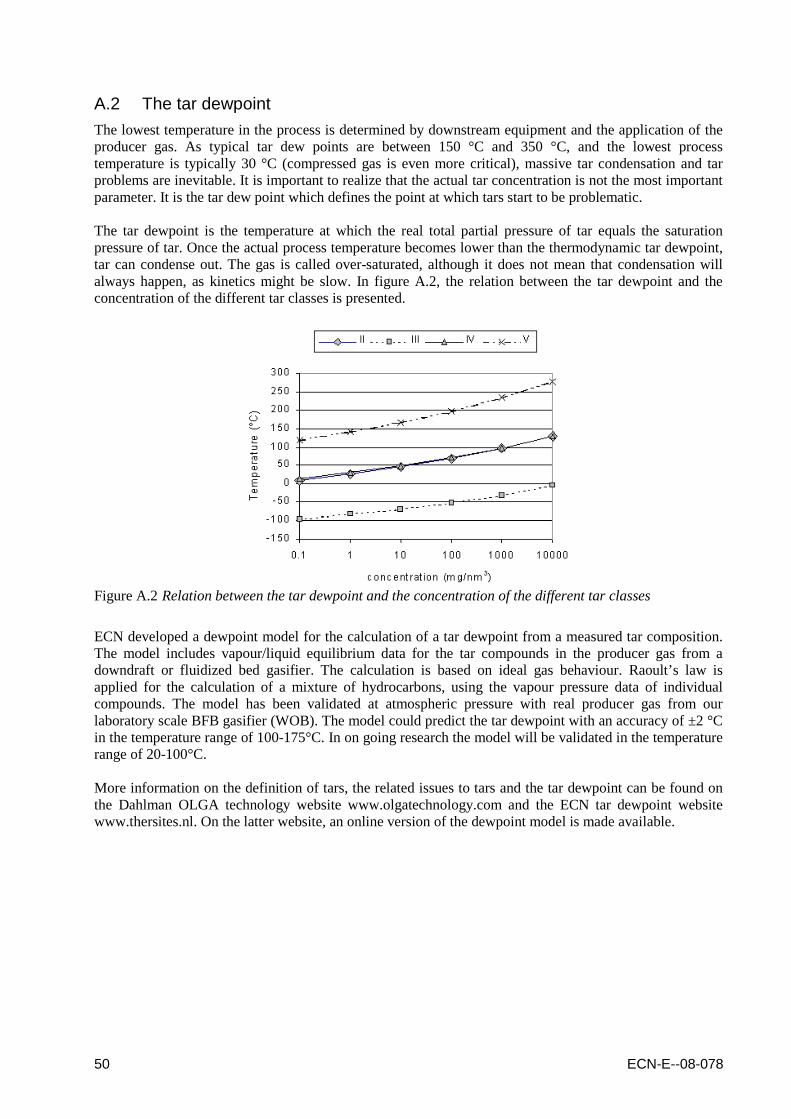
50 ECN-E--08-078
A.2 The tar dewpoint
The lowest temperature in the process is determined by downstream equipment and the application of the producer gas. As typical tar dew points are between 150 °C and 350 °C, and the lowest process temperature is typically 30 °C (compressed gas is even more critical), massive tar condensation and tar problems are inevitable. It is important to realize that the actual tar concentration is not the most important parameter. It is the tar dew point which defines the point at which tars start to be problematic. The tar dewpoint is the temperature at which the real total partial pressure of tar equals the saturation pressure of tar. Once the actual process temperature becomes lower than the thermodynamic tar dewpoint, tar can condense out. The gas is called over-saturated, although it does not mean that condensation will always happen, as kinetics might be slow. In figure A.2, the relation between the tar dewpoint and the concentration of the different tar classes is presented.
Figure A.2 Relation between the tar dewpoint and the concentration of the different tar classes
ECN developed a dewpoint model for the calculation of a tar dewpoint from a measured tar composition. The model includes vapour/liquid equilibrium data for the tar compounds in the producer gas from a downdraft or fluidized bed gasifier. The calculation is based on ideal gas behaviour. Raoult’s law is applied for the calculation of a mixture of hydrocarbons, using the vapour pressure data of individual compounds. The model has been validated at atmospheric pressure with real producer gas from our laboratory scale BFB gasifier (WOB). The model could predict the tar dewpoint with an accuracy of ±2 °C in the temperature range of 100-175°C. In on going research the model will be validated in the temperature range of 20-100°C. More information on the definition of tars, the related issues to tars and the tar dewpoint can be found on the Dahlman OLGA technology website www.olgatechnology.com and the ECN tar dewpoint website www.thersites.nl. On the latter website, an online version of the dewpoint model is made available.

ECN-E--08-078 51
Appendix B Names and structures of tar compounds
Table B.1 Names and structures of tar compounds
(Trivial) Name Tar class
Structure Elementary composition
Molecular weight (g/mol)
Boiling point (°C)
Acenaphtene 4
C12H10 154.21 279
Acenaphtylene 4
C12H8 152.19 265-275
Anthracene 4
C14H10 178.23 340
Anthanthrene = Dibenzo(def,
mno)chrysene = Dibenzo(cd,jk)pyrene
5
C22H12 276.33
Benzene
C6H6 78.11 80
Benzo(b)fluoranthene = 3,4-Benzofluoranthene
5
C20H12 252.31

52 ECN-E--08-078
Benzo(j)fluoranthene = 10,11-
Benzofluoranthene
5
C20H12 252.31
Benzo(k)fluoranthene = 11,12-
Benzofluoranthene
5
C20H12 252.31 480
Benzofurane 2
C8H6O 118.13 174
Benzo(ghi)perylene 5
C22H12 276.33
Benzo(c)phenanthrene =
3,4-Benzophenanthrene
5
C18H12 228.29
Benzo(a)pyrene = 1,2-Benzopyrene
5
C20H12 252.31 310-312
Benzo(e)pyrene = 3,4-Benzopyrene
5
C20H12 252.31 310-312

ECN-E--08-078 53
Benzoquinoline 2
C13H9N 179.22 338-350
Benzothiophene 2
C8H6S 134.19 221
Biphenyl 4
C12H10 154.21 256
Catechol = 1,2-Dihydroxybenzene
2
C6H6O2 110.11 245
Cellulose
(C6H11O5)n
Chrysene = 1,2-Benzophenanthrene
5
C18H12 228.29 448
Coniferyl alcohol 2 C10H12O3 180.20 163-165
Coronene = Hexabenzobenzene
5
C24H12 300.35 525
Coumaryl alcohol 2
C9H10O2 150.17

54 ECN-E--08-078
o-Cresol = 2-Hydroxytoluenem-
Cresol = 3-Hydroxytoluenep-
Cresol = 4-Hydroxytoluene
2
C7H8O 108.13 191 202 202
Dibenzo(a,f)anthracene =
1,2:7,8- Dibenzanthracene
5
C22H14 278.35
Dibenzo(a,h)anthracene =
1,2:5,6 Dibenzanthracene
5
C16H10 278.35
Dibenzo(f,h)anthracene =
1,2:3,4 Dibenzanthracene
5
C22H14 278.35
Dibenzofurane 2
C12H8O 168.19 285-287
Dibenzothiophene 2
C12H8S 184.26 332.5
Fluoranthene = 1,2 Benzacenaphtene
4
C16H10 202.25 375
Fluorene 4
C13H10 166.22 293-295

ECN-E--08-078 55
Furane 2
C4H4O 68.07 31
Guiaicol = Catechol monomethyl
ether = 3-Methoxyphenol
2
C7H8O2 124.13 206
Indene 4
C9H8 116.16 183
Indeno(1,2,3-cd)pyrene 5
C22H12 276.33
Indole 2
C8H7N 117.15 254
Isokinoline = Isoquinoline
2
C9H7N 129.16 242
Levoglucosan 2
C6H10O5 162.14
Naphtacene = 2,3 Benzanthracene
5
C9H8 228.29 sub
Naphthalene 4
C10H8 128.17 218

56 ECN-E--08-078
Naphtanthracene = 1,2 Benzanthracene
5
C18H12 228.29 435 (sub)
Perylene = Per-dinaphthalene
4
C20H12 252.31
Phenanthrene 4
C14H10 178.23 340
Phenol 2
C6H6O 94.11 182
a-Picoline = 2-Methylpyridineb-
Picoline = 3-Methylpyridineg-
Picoline = 4-Methylpyridine
2
C6H7N 93.12 129 144 145
Pyrene = Benzo(d,e,f)phenanthre
ne
5
C16H10 202.25 393
Pyridine 2
C5H5N 79.10 116
Pyrrole 2
C4H5N 67.09 130-131
Quinoline = Benzo(b)pyridine
2
C9H7N 129.16 238

ECN-E--08-078 57
Styrene 3
C8H8 104.15 145
Sinapyl alcohol = Syringenin
2 C11H14O4 210.22
Thiophene 2
C4H4S 84.13 84
Toluene 3
C7H8 92.14 111
Triphenyleen = 9,10
Benzophenanthreen
5
C18H12 228.29 425
o-Xylene = 1,2 Dimethylbenzenem-
Xylene = 1,3 Dimethylbenzenep-
Xylene = 1,4 Dimethylbenzene
2
C8H10 106.16 144 139 138

58 ECN-E--08-078

ECN-E--08-078 59
Appendix C Who is who
In this appendix a list of companies or RD&D institutes working on gas cleaning technologies is provided. This is considered to be relevant as in the status report itself it is difficult to refer to all players active in the field of gas cleaning. As such, the main report focused on describing the different technologies and the development status, while in this appendix an alphabetically ordered overview is given of the companies active in the field of gas cleaning with the technology worked on (§C.1) and the specific technologies being developed or patented by different companies (§C.2). The section of the status report in which the specific technology (hence not the company) is discussed as well as the status of the technology development at the end of 2008, is mentioned as well. For the status of the technology development, the following indices are used: ●● = commercially available
● = commercially available, though not (yet demonstrated) for biomass related thermochemical technologies
○○ = demonstration phase (pilot or larger)
○ = demonstration phase, though not for biomass related thermochemical technologies
□□ = lab-scale testing phase
□ = lab-scale testing phase, though not for biomass related thermochemical technologies
? = current status unknown or unsure
The author of the status report at hand is aware of the fact that this “who is who” list will never be complete. Companies who find their technology development missing may therefore send a brief e-mail with information on their company, the technology developed and some information on this technology. If an update of this “who is who” is considered to be necessary in time, the author will adjust the digital version of this report and will make it available via the publications website of the Energy research Centre of the Netherlands (www.ecn.nl/publications). C.1 Companies working on…
Company Technology aimed at removal of …
Detailed information Status 2008
Status report
Andritz Tars (cracking/reforming) Catalytic cracking and reforming (see VTT) ○○ §2.1
BTG Tars (cracking/reforming) Reverse-flow catalytic tar converter RF®TC ○○ / ? §2.1
Cutec Tars (cracking/reforming) Catalytic cracking (downstream pilot gasifier) ○○ / ? §2.1
Ebara Corp Tars (cracking/reforming) Catalytic reforming ? §2.1
ECN Tars (cracking/reforming) Plasma cracking (via the GlidArc process) □□ / ? §2.1
ECN Tars (cracking/reforming) Catalytic cracking (via the TREC process) □□ / ? §2.1
Enviropower Tars (cracking/reforming) Catalytic cracking ? §2.1
Europlasma Tars (cracking/reforming) Plasma cracking ? §2.1
FZK Tars (cracking/reforming) Partial oxidation ○○ §2.1
FZK Tars (cracking/reforming) Catalytic cracking (with char) ○○ / ? §2.1
IFP Tars (cracking/reforming) Catalytic cracking and reforming ? §2.1
Krupp Koppers Tars (cracking/reforming) Partial oxidation ? §2.1
Madison Tars (cracking/reforming) Catalytic filters □□ / ? §2.1
Neste Oil Tars (cracking/reforming) Catalytic cracking and reforming (see VTT) ○○ §2.1
Nexterra Tars (cracking/reforming) Partial oxidation ○○ §2.1
Plasco Tars (cracking/reforming) Plasma cracking ●● §2.1
Stora Enso Tars (cracking/reforming) Catalytic cracking and reforming (see VTT) ○○ §2.1
Technical University of Delft Tars (cracking/reforming) Catalytic cracking and reforming □□ §2.1
Technical University of Eindhoven Tars (cracking/reforming) Partial oxidation □ §2.1

60 ECN-E--08-078
Company Technology aimed at removal of …
Detailed information Status 2008
Status report
Technical University of Eindhoven Tars (cracking/reforming) Plasma cracking □ §2.1
TPS Tars (cracking/reforming) Thermal as well as catalytic tar cracking ○○ / ? §2.1
Twente University Tars (cracking/reforming) Catalytic cracking (with char) □□ / ? §2.1
Umsicht Tars (cracking/reforming) Catalytic cracking (downstream pilot gasifier) ○○ / ? §2.1
UPM Kymene Tars (cracking/reforming) Catalytic cracking and reforming (see VTT) ○○ §2.1
Valtion Teknillinen Tars (cracking/reforming) Catalytic cracking ? §2.1
VTT Tars (cracking/reforming) Catalytic cracking and reforming ○○ §2.1
Babcock & Wilcox Vølund Tars (physical removal) Water based scrubbing incl. TARWATC ●● §2.2
Beth Tars (physical removal) Wet ESP filter ●● §2.2
BTG Tars (physical removal) Rotating particle separation ○○ / ? §2.2
CTU Tars (physical removal) RME based scrubbing technology (see TUV) ●● §2.2
Dahlman Tars (physical removal) Oil based scrubbing OLGA ●● §2.2
ECN Tars (physical removal) Oil based scrubbing OLGA (see Dahlman) ●● §2.2
ECN Tars (physical removal) Sawdust filter ○○ / ? §2.2
ECN Tars (physical removal) Rotating particle separator ○○ / ? §2.2
ECN Tars (physical removal) Water scrubbing ○○ / ? §2.2
Energy Process Technologies Tars (physical removal) Oil scrubber ? §2.2
Envitec Tars (physical removal) Wet scrubbing technology ? §2.2
ETH Tars (physical removal) Rotating particle separation ○○ / ? §2.2
HoSt Tars (physical removal) Water scrubbing ○○ / ? §2.2
HoSt Tars (physical removal) Sawdust filter ○○ / ? §2.2
JFE engineering Tars (physical removal) Water based scrubbing (see Babcock & Wilcox) ●● §2.2
Pall Tars (physical removal) Catalytic filter ○○ §2.2
Relax Umwelttechnik GmbH Tars (physical removal) Water based scrubbing (see Babcock & Wilcox) ●● §2.2
Repotec Tars (physical removal) RME based scrubbing ●● §2.2
Schumacher Tars (physical removal) Catalytic filter ○○ / ? §2.2
Dahlman Chlorine Oil based OLGA scrubbing (in particular dioxins) ●● §3.1
ECN Chlorine Sodium as well as calcium based adsorption □□ §3.1
ECN Chlorine Oil based OLGA scrubbing (in particular dioxins) ●● §3.1
FZK Chlorine Carbon doped PP based absorption (ADIOX) ○○ / ? §3.1
Götaverken Miljö Chlorine Carbon doped PP based absorption (ADIOX) ○○ / ? §3.1
Basf Sulfur Amine scrubber ● §3.2
Bayer Sulfur Catalytic removal ● §3.2
Catalysts & Chem Ind Co Sulfur Catalytic removal ● / ? §3.2
Clearwater International Llc Sulfur Amine scrubber ● / ? §3.2
Comprimo Sulfur Hydrogenation, absorption and adsorption ● / ? §3.2
Dorchak Mary Anne Sulfur Catalytic removal ? §3.2
DOW Sulfur Amine scrubber ● §3.2
ECN Sulfur Fixed bed HDS as well as ZnO based absorption □□ §3.2
Elf aquitaine Sulfur Regenerative absorption (in particular mercaptans) ? §3.2
Enviropower Inc Sulfur Regenerative absorption ? §3.2
Envirotherm Sulfur Dry and wet desulfurisation ●● §3.2
Envitec Sulfur Amine scrubber ? §3.2
Gastec NV Sulfur Hydrogenation, absorption and absorption ● / ? §3.2
Haldor Topsøe Sulfur Catalytic hydrogenation and absorption ● §3.2
JGC Corp Sulfur Catalytic hydrogenation (in particular COS) ? §3.2
Johnson Matthey Sulfur Catalytic hydrogenation ● §3.2
Kellogg Sulfur Regenerative absorption ? §3.2
Kema Sulfur Catalytic conversion and adsorption ? §3.2
Krupp Koppers Sulfur Amine scrubbing ? §3.2
Leuna Raffineriegesellschaft Sulfur Regenerative adsorption ? §3.2
Linde Sulfur Methanol scrubbing (Rectisol) ● §3.2
Lurgi Sulfur Methanol scrubbing (Rectisol) ● §3.2
McDermott Technology Inc Sulfur Regenerative adsorption ? §3.2
Mitsubishi Heavy Industries Sulfur High-temperature adsorption □ §3.2
Paques Sulfur Biological (THIOPAQ) ● §3.2
PSI Sulfur Fixed bed HDS as well as absorption ○○ §3.2
RCS Sulfur Regenerative adsorption ? §3.2

ECN-E--08-078 61
Company Technology aimed at removal of …
Detailed information Status 2008
Status report
RTI Sulfur Regenerative adsorption □ §3.2
Süd Chemie Sulfur Catalytic decomposition (in particular COS) ● §3.2
SulphCatch Sulfur Adsorption of organic sulfur compounds ● §3.2
Teco Energy Inc Sulfur Wet scrubbing as well as hydrolysis (in particular COS) ? §3.2
Texaco Sulfur Hydrogenation, absorption and absorption ● §3.2
Tokyo Gas Sulfur Regenerative zeolite ion based desulfurisation ● / ? §3.2
Uhde Sulfur Amine scrubber ● §3.2
Union Carbide Chem Plastic Sulfur Glycol based scrubber ● §3.2
University of Birmingham Sulfur Regenerative absorption ? §3.2
UOP Sulfur Dimethylether & PE-glycol adsorption (Selexol) ● §3.2
Air Liquide NH3 and HCN Water scrubbing ● §3.3
Basf NH3 and HCN Catalytic conversion ● §3.3
Catalysts & Chem Ind Co NH3 and HCN Catalytic conversion ● / ? §3.3
Dahlman NH3 and HCN Water scrubbing ●● §3.3
ECN NH3 and HCN Water scrubbing □□ / ? §3.3
Envirotherm NH3 and HCN Catalytic reforming ●● §3.3
Exxon NH3 and HCN Catalytic conversion (in particular HCN) ? §3.3
Exxon NH3 and HCN Water scrubbing ? §3.3
HoSt NH3 and HCN Water scrubbing ●● §3.3
Huels Chemische Werke NH3 and HCN Catalytic conversion (in particular HCN) ? §3.3
JGC Corp NH3 and HCN Catalytic conversion ? §3.3
Krupp Koppers NH3 and HCN Amine scrubbing ? §3.3
Linde NH3 and HCN Amine based scrubbing ● §3.3
Linde NH3 and HCN Methanol based scrubbing (Rectisol) ● §3.3
Lurgi NH3 and HCN Methanol based scrubbing (Rectisol) ● §3.3
Mitsubishi Heavy Industries NH3 and HCN Water scrubbing ? §3.3
Nippon Kokan NH3 and HCN Catalytic conversion ? §3.3
Paques NH3 and HCN Biological (ANAMMOX) ● §3.3
Shell NH3 and HCN Water based scrubbing ? §3.3
Süd Chemie NH3 and HCN Catalytic decomposition (in particular HCN) ● §3.3
Valtion Teknillinen NH3 and HCN Catalytic conversion (in particular NH3) ? §3.3
Air Liquide Carbon dioxide Pressure swing based CO2 adsorption ● §3.4
Basf Carbon dioxide Amine scrubber ● §3.4
Cirmac Carbon dioxide Amine based CO2 absorption ● §3.4
Cirmac Carbon dioxide Pressure swing based CO2 adsorption ● §3.4
Cirmac Carbon dioxide Membrane based CO2 separation ● §3.4
DMT Carbon dioxide Amine based CO2 absorption ● §3.4
GTS Carbon dioxide Cryogenic separation of CO2 ● §3.4
Linde Carbon dioxide Amine based CO2 absorption ● §3.4
Linde Carbon dioxide Methanol based scrubbing (Rectisol) ● §3.4
Lurgi Carbon dioxide Methanol based scrubbing (Rectisol) ● §3.4
Process Systems Int Carbon dioxide Cryogenic as well as membrane separation of CO2 ? §3.4
Purac Carbon dioxide Amine based CO2 absorption ● §3.4
RWE Carbon dioxide Pressure swing based CO2 adsorption ? §3.4
TNO Carbon dioxide Regenerative CO2 absorption ? §3.4
Uhde Carbon dioxide Amine scrubber ● §3.4
Union Carbide Chem Plastic Carbon dioxide Glycol based scrubber ● §3.4
University of California Carbon dioxide Selective separation using CO2 hydrate promoters ? §3.4
UOP Carbon dioxide Dimethylether & PE-glycol adsorption (Selexol) ● §3.4
ECN Unsaturated hydrocarbons Hydrogenation and reforming □□ §3.5
Engelhard Unsaturated hydrocarbons Water based scrubbing ? §3.5
Haldor Topsøe Unsaturated hydrocarbons Hydrogenation and reforming catalyst ● §3.5
Johnson Matthey Unsaturated hydrocarbons Hydrogenation and reforming catalyst ● §3.5
Linde Unsaturated hydrocarbons Methanol based scrubbing (Rectisol) ● §3.5
Lurgi Unsaturated hydrocarbons Methanol based scrubbing (Rectisol) ● §3.5
PSI Unsaturated hydrocarbons Scrubbing, hydrogenation and reforming ○○ §3.5
Süd Chemie Unsaturated hydrocarbons Hydrogenation and reforming catalyst ● §3.5
Alhström Particles and alkalis Hot gas filters ●● §3.6

62 ECN-E--08-078
Company Technology aimed at removal of …
Detailed information Status 2008
Status report
Alstom Power Particles and alkalis ESP filters ●● §3.6
Babcock & Wilcox Vølund Particles and alkalis ESP filters as well as water based scrubbers ●● §3.6
BETH Particles and alkalis ESP filters ●● §3.6
Dahlman Particles and alkalis Hot gas filters ● / □□ §3.6
Destec Energy Inc Particles and alkalis Filters ? §3.6
DMT Particles and alkalis ESP filter ? §3.6
ECN Particles and alkalis Hot gas filters □□ / ○○ / ? §3.6
ECN Particles and alkalis ESP filter (part of OLGA) ○○ §3.6
ECN Particles and alkalis Rotating particle separator ○○ / ? §3.6
ECN Particles and alkalis Cyclones ○○ §3.6
Energy Process Technologies Particles and alkalis Oil scrubber ? §3.6
Envitec Particles and alkalis ESP filters and venturi scrubbers ? §3.6
EWK Particles and alkalis ESP filters (in particular for oil) □□ / ? §3.6
Foster Wheeler Particles and alkalis Hot gas filter ●● §3.6
HoSt Particles and alkalis Cyclones ○○ §3.6
HoSt Particles and alkalis Barrier filters ○○ §3.6
IFP Particles and alkalis Cyclones ? §3.6
McGill Air Clean Particles and alkalis ESP filters ●● §3.6
Michaelis Particles and alkalis ESP filters (in particular for oil and tar mist) ● §3.6
MikroPul GmbH Particles and alkalis ESP filters (in particular for oil and tar mist) ● §3.6
Norsk Hydro Particles and alkalis Water based scrubber including water filtration ? §3.6
Pall Particles and alkalis Hot gas filter ●● §3.6
PPC Particles and alkalis ESP filters ●● §3.6
Schumacher Particles and alkalis Hot gas filter ●● §3.6
Shell Particles and alkalis Sulfide based gas polishing ? §3.6
Siemens Westinghouse Particles and alkalis Membrane as well as ESP filters for sticky dust ●● §3.6
Superior Micropowders Particles and alkalis Demisters ? §3.6
Texaco Particles and alkalis Water based scrubber (via quench) ? §3.6
Tri-Mer Particles and alkalis Cloud chamber scrubber ● §3.6
TurboSonic Particles and alkalis ESP filters ● §3.6
Westinghouse Particles and alkalis High-temperature adsorption and ceramic filtering ? §3.6
C.2 Technologies developed by…
Company Technology aimed at removal of …
Detailed information Status 2008
Status report
Air Liquide NH3 and HCN Water scrubbing ● §3.3
Air Liquide Carbon dioxide Pressure swing based CO2 adsorption ● §3.4
Alhström Particles and alkalis Hot gas filters ●● §3.6
Alstom Power Particles and alkalis ESP filters ●● §3.6
Andritz Tars (cracking/reforming) Catalytic cracking and reforming (see VTT) ○○ §2.1
Babcock & Wilcox Vølund Tars (physical removal) Water based scrubbing incl. TARWATC ●● §2.2
Babcock & Wilcox Vølund Particles and alkalis ESP filters as well as water based scrubbers ●● §3.6
Basf Sulfur Amine scrubber ● §3.2
Basf NH3 and HCN Catalytic conversion ● §3.3
Basf Carbon dioxide Amine scrubber ● §3.4
Bayer Sulfur Catalytic removal ● §3.2
Beth Tars (physical removal) Wet ESP filter ●● §2.2
BETH Particles and alkalis ESP filters ●● §3.6
BTG Tars (cracking/reforming) Reverse-flow catalytic tar converter RF®TC ○○ / ? §2.1
BTG Tars (physical removal) Rotating particle separation ○○ / ? §2.2
Catalysts & Chem Ind Co Sulfur Catalytic removal ● / ? §3.2
Catalysts & Chem Ind Co NH3 and HCN Catalytic conversion ● / ? §3.3
Cirmac Carbon dioxide Amine based CO2 absorption ● §3.4
Cirmac Carbon dioxide Pressure swing based CO2 adsorption ● §3.4
Cirmac Carbon dioxide Membrane based CO2 separation ● §3.4
Clearwater International Llc Sulfur Amine scrubber ● / ? §3.2
Comprimo Sulfur Hydrogenation, absorption and adsorption ● / ? §3.2

ECN-E--08-078 63
Company Technology aimed at removal of …
Detailed information Status 2008
Status report
CTU Tars (physical removal) RME based scrubbing technology (see TUV) ●● §2.2
Cutec Tars (cracking/reforming) Catalytic cracking (downstream pilot gasifier) ○○ / ? §2.1
Dahlman Tars (physical removal) Oil based scrubbing OLGA ●● §2.2
Dahlman Chlorine Oil based OLGA scrubbing (in particular dioxins) ●● §3.1
Dahlman NH3 and HCN Water scrubbing ●● §3.3
Dahlman Particles and alkalis Hot gas filters ● / □□ §3.6
Destec Energy Inc Particles and alkalis Filters ? §3.6
DMT Carbon dioxide Amine based CO2 absorption ● §3.4
DMT Particles and alkalis ESP filter ? §3.6
Dorchak Mary Anne Sulfur Catalytic removal ? §3.2
DOW Sulfur Amine scrubber ● §3.2
Ebara Corp Tars (cracking/reforming) Catalytic reforming ? §2.1
ECN Tars (cracking/reforming) Plasma cracking (via the GlidArc process) □□ / ? §2.1
ECN Tars (cracking/reforming) Catalytic cracking (via the TREC process) □□ / ? §2.1
ECN Tars (physical removal) Oil based scrubbing OLGA (see Dahlman) ●● §2.2
ECN Tars (physical removal) Sawdust filter ○○ / ? §2.2
ECN Tars (physical removal) Rotating particle separator ○○ / ? §2.2
ECN Tars (physical removal) Water scrubbing ○○ / ? §2.2
ECN Chlorine Sodium as well as calcium based adsorption □□ §3.1
ECN Chlorine Oil based OLGA scrubbing (in particular dioxins) ●● §3.1
ECN Sulfur Fixed bed HDS as well as ZnO based absorption □□ §3.2
ECN NH3 and HCN Water scrubbing □□ / ? §3.3
ECN Unsaturated hydrocarbons Hydrogenation and reforming □□ §3.5
ECN Particles and alkalis Hot gas filters □□ / ○○ / ? §3.6
ECN Particles and alkalis ESP filter (part of OLGA) ○○ §3.6
ECN Particles and alkalis Rotating particle separator ○○ / ? §3.6
ECN Particles and alkalis Cyclones ○○ §3.6
Elf aquitaine Sulfur Regenerative absorption (in particular mercaptans) ? §3.2
Energy Process Technologies Tars (physical removal) Oil scrubber ? §2.2
Energy Process Technologies Particles and alkalis Oil scrubber ? §3.6
Engelhard Unsaturated hydrocarbons Water based scrubbing ? §3.5
Enviropower Tars (cracking/reforming) Catalytic cracking ? §2.1
Enviropower Inc Sulfur Regenerative absorption ? §3.2
Envirotherm Sulfur Dry and wet desulfurisation ●● §3.2
Envirotherm NH3 and HCN Catalytic reforming ●● §3.3
Envitec Tars (physical removal) Wet scrubbing technology ? §2.2
Envitec Sulfur Amine scrubber ? §3.2
Envitec Particles and alkalis ESP filters and venturi scrubbers ? §3.6
ETH Tars (physical removal) Rotating particle separation ○○ / ? §2.2
Europlasma Tars (cracking/reforming) Plasma cracking ? §2.1
EWK Particles and alkalis ESP filters (in particular for oil) □□ / ? §3.6
Exxon NH3 and HCN Catalytic conversion (in particular HCN) ? §3.3
Exxon NH3 and HCN Water scrubbing ? §3.3
Foster Wheeler Particles and alkalis Hot gas filter ●● §3.6
FZK Tars (cracking/reforming) Partial oxidation ○○ §2.1
FZK Tars (cracking/reforming) Catalytic cracking (with char) ○○ / ? §2.1
FZK Chlorine Carbon doped PP based absorption (ADIOX) ○○ / ? §3.1
Gastec NV Sulfur Hydrogenation, absorption and absorption ● / ? §3.2
Götaverken Miljö Chlorine Carbon doped PP based absorption (ADIOX) ○○ / ? §3.1
GTS Carbon dioxide Cryogenic separation of CO2 ● §3.4
Haldor Topsøe Sulfur Catalytic hydrogenation and absorption ● §3.2
Haldor Topsøe Unsaturated hydrocarbons Hydrogenation and reforming catalyst ● §3.5
HoSt Tars (physical removal) Water scrubbing ○○ / ? §2.2
HoSt Tars (physical removal) Sawdust filter ○○ / ? §2.2
HoSt NH3 and HCN Water scrubbing ●● §3.3
HoSt Particles and alkalis Cyclones ○○ §3.6
HoSt Particles and alkalis Barrier filters ○○ §3.6
Huels Chemische Werke NH3 and HCN Catalytic conversion (in particular HCN) ? §3.3

64 ECN-E--08-078
Company Technology aimed at removal of …
Detailed information Status 2008
Status report
IFP Tars (cracking/reforming) Catalytic cracking and reforming ? §2.1
IFP Particles and alkalis Cyclones ? §3.6
JFE engineering Tars (physical removal) Water based scrubbing (see Babcock & Wilcox) ●● §2.2
JGC Corp Sulfur Catalytic hydrogenation (in particular COS) ? §3.2
JGC Corp NH3 and HCN Catalytic conversion ? §3.3
Johnson Matthey Sulfur Catalytic hydrogenation ● §3.2
Johnson Matthey Unsaturated hydrocarbons Hydrogenation and reforming catalyst ● §3.5
Kellogg Sulfur Regenerative absorption ? §3.2
Kema Sulfur Catalytic conversion and adsorption ? §3.2
Krupp Koppers Tars (cracking/reforming) Partial oxidation ? §2.1
Krupp Koppers Sulfur Amine scrubbing ? §3.2
Krupp Koppers NH3 and HCN Amine scrubbing ? §3.3
Leuna Raffineriegesellschaft Sulfur Regenerative adsorption ? §3.2
Linde Sulfur Methanol scrubbing (Rectisol) ● §3.2
Linde NH3 and HCN Amine based scrubbing ● §3.3
Linde NH3 and HCN Methanol based scrubbing (Rectisol) ● §3.3
Linde Carbon dioxide Amine based CO2 absorption ● §3.4
Linde Carbon dioxide Methanol based scrubbing (Rectisol) ● §3.4
Linde Unsaturated hydrocarbons Methanol based scrubbing (Rectisol) ● §3.5
Lurgi Sulfur Methanol scrubbing (Rectisol) ● §3.2
Lurgi NH3 and HCN Methanol based scrubbing (Rectisol) ● §3.3
Lurgi Carbon dioxide Methanol based scrubbing (Rectisol) ● §3.4
Lurgi Unsaturated hydrocarbons Methanol based scrubbing (Rectisol) ● §3.5
Madison Tars (cracking/reforming) Catalytic filters □□ / ? §2.1
McDermott Technology Inc Sulfur Regenerative adsorption ? §3.2
McGill Air Clean Particles and alkalis ESP filters ●● §3.6
Michaelis Particles and alkalis ESP filters (in particular for oil and tar mist) ● §3.6
MikroPul GmbH Particles and alkalis ESP filters (in particular for oil and tar mist) ● §3.6
Mitsubishi Heavy Industries Sulfur High-temperature adsorption □ §3.2
Mitsubishi Heavy Industries NH3 and HCN Water scrubbing ? §3.3
Neste Oil Tars (cracking/reforming) Catalytic cracking and reforming (see VTT) ○○ §2.1
Nexterra Tars (cracking/reforming) Partial oxidation ○○ §2.1
Nippon Kokan NH3 and HCN Catalytic conversion ? §3.3
Norsk Hydro Particles and alkalis Water based scrubber including water filtration ? §3.6
Pall Tars (physical removal) Catalytic filter ○○ §2.2
Pall Particles and alkalis Hot gas filter ●● §3.6
Paques Sulfur Biological (THIOPAQ) ● §3.2
Paques NH3 and HCN Biological (ANAMMOX) ● §3.3
Plasco Tars (cracking/reforming) Plasma cracking ●● §2.1
PPC Particles and alkalis ESP filters ●● §3.6
Process Systems Int Carbon dioxide Cryogenic as well as membrane separation of CO2 ? §3.4
PSI Sulfur Fixed bed HDS as well as absorption ○○ §3.2
PSI Unsaturated hydrocarbons Scrubbing, hydrogenation and reforming ○○ §3.5
Purac Carbon dioxide Amine based CO2 absorption ● §3.4
RCS Sulfur Regenerative adsorption ? §3.2
Relax Umwelttechnik GmbH Tars (physical removal) Water based scrubbing (see Babcock & Wilcox) ●● §2.2
Repotec Tars (physical removal) RME based scrubbing ●● §2.2
RTI Sulfur Regenerative adsorption □ §3.2
RWE Carbon dioxide Pressure swing based CO2 adsorption ? §3.4
Schumacher Tars (physical removal) Catalytic filter ○○ / ? §2.2
Schumacher Particles and alkalis Hot gas filter ●● §3.6
Shell NH3 and HCN Water based scrubbing ? §3.3
Shell Particles and alkalis Sulfide based gas polishing ? §3.6
Siemens Westinghouse Particles and alkalis Membrane as well as ESP filters for sticky dust ●● §3.6
Stora Enso Tars (cracking/reforming) Catalytic cracking and reforming (see VTT) ○○ §2.1
Süd Chemie Sulfur Catalytic decomposition (in particular COS) ● §3.2
Süd Chemie NH3 and HCN Catalytic decomposition (in particular HCN) ● §3.3
Süd Chemie Unsaturated hydrocarbons Hydrogenation and reforming catalyst ● §3.5

ECN-E--08-078 65
Company Technology aimed at removal of …
Detailed information Status 2008
Status report
SulphCatch Sulfur Adsorption of organic sulfur compounds ● §3.2
Superior Micropowders Particles and alkalis Demisters ? §3.6
Technical University of Delft Tars (cracking/reforming) Catalytic cracking and reforming □□ §2.1
Technical University of Eindhoven Tars (cracking/reforming) Partial oxidation □ §2.1
Technical University of Eindhoven Tars (cracking/reforming) Plasma cracking □ §2.1
Teco Energy Inc Sulfur Wet scrubbing as well as hydrolysis (in particular COS) ? §3.2
Texaco Sulfur Hydrogenation, absorption and absorption ● §3.2
Texaco Particles and alkalis Water based scrubber (via quench) ? §3.6
TNO Carbon dioxide Regenerative CO2 absorption ? §3.4
Tokyo Gas Sulfur Regenerative zeolite ion based desulfurisation ● / ? §3.2
TPS Tars (cracking/reforming) Thermal as well as catalytic tar cracking ○○ / ? §2.1
Tri-Mer Particles and alkalis Cloud chamber scrubber ● §3.6
TurboSonic Particles and alkalis ESP filters ● §3.6
Twente University Tars (cracking/reforming) Catalytic cracking (with char) □□ / ? §2.1
Uhde Sulfur Amine scrubber ● §3.2
Uhde Carbon dioxide Amine scrubber ● §3.4
Umsicht Tars (cracking/reforming) Catalytic cracking (downstream pilot gasifier) ○○ / ? §2.1
Union Carbide Chem Plastic Sulfur Glycol based scrubber ● §3.2
Union Carbide Chem Plastic Carbon dioxide Glycol based scrubber ● §3.4
University of Birmingham Sulfur Regenerative absorption ? §3.2
University of California Carbon dioxide Selective separation using CO2 hydrate promoters ? §3.4
UOP Sulfur Dimethylether & PE-glycol adsorption (Selexol) ● §3.2
UOP Carbon dioxide Dimethylether & PE-glycol adsorption (Selexol) ● §3.4
UPM Kymene Tars (cracking/reforming) Catalytic cracking and reforming (see VTT) ○○ §2.1
Valtion Teknillinen Tars (cracking/reforming) Catalytic cracking ? §2.1
Valtion Teknillinen NH3 and HCN Catalytic conversion (in particular NH3) ? §3.3
VTT Tars (cracking/reforming) Catalytic cracking and reforming ○○ §2.1
Westinghouse Particles and alkalis High-temperature adsorption and ceramic filtering ? §3.6


