Cyclotrons 2007, september 30th to 5 october 2007 F. CHAUTARD STATUS REPORT ON SPIRAL1 F. Chautard October 2 nd , 2007 n Assessment of GANIL/SPIRAL operation n Technical achievements n Present R&D n Possible developments
Transcript
Cyc
lotr
ons
2007
, sep
tem
ber3
0th
to 5
octo
ber2
007
F. C
HA
UTA
RD
STATUS REPORT ON SPIRAL1 F. Chautard
October 2nd, 2007
n Assessment of GANIL/SPIRAL operationn Technical achievementsn Present R&D n Possible developments
Cyc
lotr
ons
2007
, sep
tem
ber3
0th
to 5
octo
ber2
007
F. C
HA
UTA
RD
SPIRAL: Radioactive ion beamswith «ISOL» method since 2001
PRODUCTION target
Heavy Ion Beams up to 95 MeV/A onto a thick carbon target
radioactive atoms
Ionisation by an ECR ion source
Acceleration and Purification in a compact cyclotron CIME
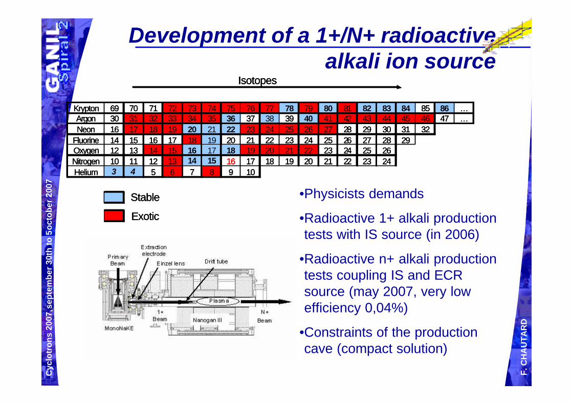
Radioactive Isotopes (He, N, O, Ne, Ar, Kr, F)
Post-acceleration by CIME cyclotron
Cyc
lotr
ons
2007
, sep
tem
ber3
0th
to 5
octo
ber2
007
F. C
HA
UTA
RD
IRRSUD : low energy beam irradiation line
[0.3, 1.0] MeV/A 1
Multi-beam operating mode:4 experiments in parallel
2
3
1α spectro
Stripper
4 SME : after a stripper, one charged state is sent to the D1 room => the medium energy exit [3.7, 13.7] MeV/A
2
High Energy Beam GANIL
[24, 95] MeV/A 3 4
Cyc
lotr
ons
2007
, sep
tem
ber3
0th
to 5
octo
ber2
007
F. C
HA
UTA
RD
Multi-beam operating mode:Beam schedule
Cyc
lotr
ons
2007
, sep
tem
ber3
0th
to 5
octo
ber2
007
F. C
HA
UTA
RD
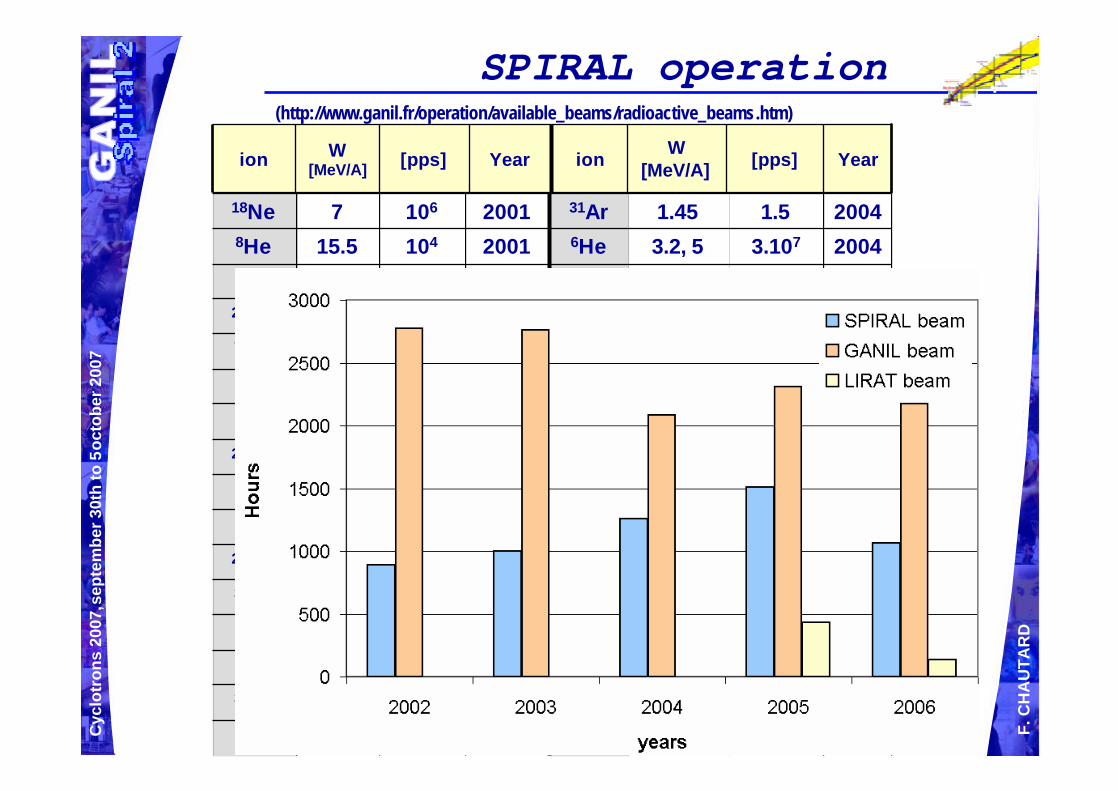
Running Statistics 2001-2006
GANIL per year: 35 weeks / 4 periods: 5700h of operating time. Leading to 7200h of beam time for users (multi-beam effect)
SPIRAL since 2001: 5000h of exotic beams / 700h of stable beams. More than 30 exotic beams
• Since few years, the accelerating cavities of the SSC’sencountered water leaks due to 25 years of functioning. • Interventions require to remove the whole cavity. • Inducing one week delay to physics experiment.
Ageing Problems and Maintenance
Corrective actions:• Replacement of defective component. • Tuning of SSC with one RF cavity.
Cyc
lotr
ons
2007
, sep
tem
ber3
0th
to 5
octo
ber2
007
F. C
HA
UTA
RD
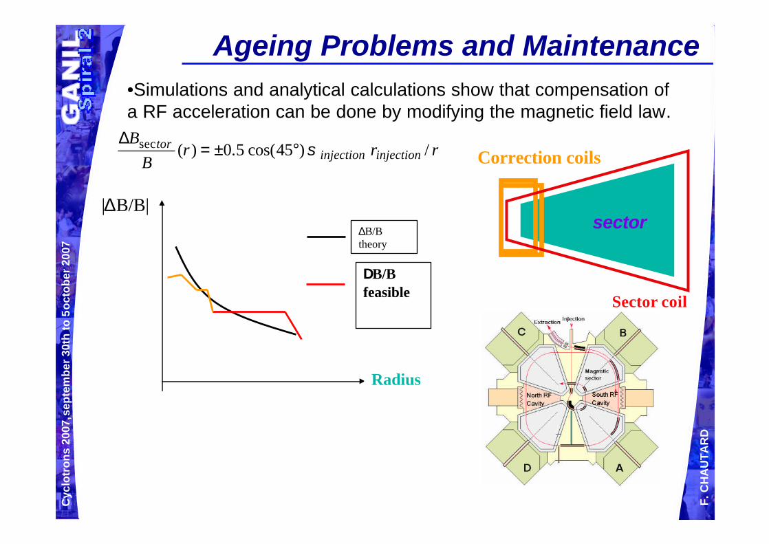
|∆B/B| ∆B/B theory
Radius
∆B/Bfeasible
rrrB
Binjectioninjection
tor /)45cos(5.0)(sec σ°±=∆
Ageing Problems and Maintenance
Correction coils
Sector coil
sector
•Simulations and analytical calculations show that compensation of a RF acceleration can be done by modifying the magnetic field law.
Cyc
lotr
ons
2007
, sep
tem
ber3
0th
to 5
octo
ber2
007
F. C
HA
UTA
RD
Ageing Problems and Maintenance
On a Radial probe: Still precession, but 90% transmission
Cyc
lotr
ons
2007
, sep
tem
ber3
0th
to 5
octo
ber2
007
F. C
HA
UTA
RD
In-Flight Separation techniques (SISSI)
In June 2007, the second solenoid S2 of the SISSI device quenched during current rising and cannot be used since. The reasons of the repetitive quenches are still unknown (ageing, device weakness, neutron effects …) : Short term alternative solutions are studied.
Ageing Problems and Maintenance
Cyc
lotr
ons
2007
, sep
tem
ber3
0th
to 5
octo
ber2
007
F. C
HA
UTA
RD
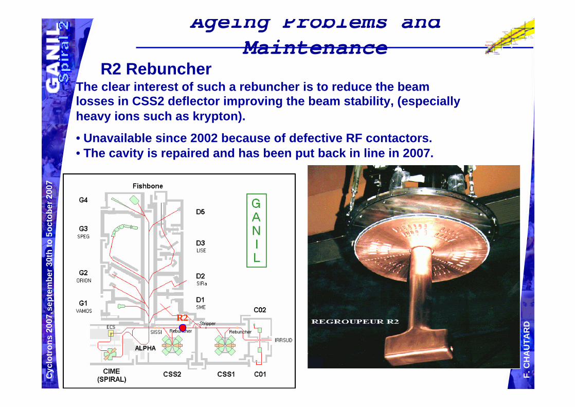
R2 RebuncherThe clear interest of such a rebuncher is to reduce the beam losses in CSS2 deflector improving the beam stability, (especially heavy ions such as krypton).
• Unavailable since 2002 because of defective RF contactors. • The cavity is repaired and has been put back in line in 2007.
Ageing Problems and Maintenance
R2
Cyc
lotr
ons
2007
, sep
tem
ber3
0th
to 5
octo
ber2
007
F. C
HA
UTA
RD
SPIRAL Facility
The SPIRAL strengths can be resumed by:
• Large Energy range of post-accelerator : from 1.2 MeV/A to 16 MeV/A (for Q/A=0.25) • Mass purification of the cyclotron R= few 10-4.• Good energy definition of the CIME beams ∆E/E < 5 10-3
• Good transmission for such an accelerator technology 20%-40%.• Great target-source selectivity + cyclotron purification giving a pure beam of most of available ion beams.• 40 isotopes available.• Possibility to run detectors developments with stable beam of CIME in a stand alone operation.
Cyc
lotr
ons
2007
, sep
tem
ber3
0th
to 5
octo
ber2
007
F. C
HA
UTA
RD
SPIRAL Facility
But SPIRAL has also its limitations:
• Still, too few radioactive ion species are available (He, O, N, Ne, Ar, Kr, F).
• Intensity is a parameter of utmost importance; It is the main limitation for most of experiments.
• The large turn number in CIME impacts the beam emittance: ∆TFWHM < 2ns and emittance ~ 16π.mm.mrd imply multi-turn extraction.
Cyc
lotr
ons
2007
, sep
tem
ber3
0th
to 5
octo
ber2
007
F. C
HA
UTA
RD
What about improvements since2001?
Cyc
lotr
ons
2007
, sep
tem
ber3
0th
to 5
octo
ber2
007
F. C
HA
UTA
RD
2004 Modification of the high voltage platform C01 (100 kVolts)
=> Beam more stable, gain of a factor 1.5 - 2 in intensity (S, Kr, Mg, Ar)36S8+ 38 µAe78Kr15+ 30 µAe
Goal: Increase the beam intensity of the sourceLimitation: space–chargeSolution: Increase the extraction voltage from 25 kV to 100 kV in two stages.First stage: extraction at 25 kV and selection to remove unwanted intense beamsSecond stage: acceleration to the wanted energy for injection into the C0
Cyc
lotr
ons
2007
, sep
tem
ber3
0th
to 5
octo
ber2
007
F. C
HA
UTA
RD
SPIRAL Working diagram extension
Cyc
lotr
ons
2007
, sep
tem
ber3
0th
to 5
octo
ber2
007
F. C
HA
UTA
RD
Tuning optimization
7%7%15%
24%21%
0
200
400
600
800
1000
1200
1400
1600
2002 2003 2004 2005 2006
years
ho
urs
SPIRAL beamsSPIRAL tuning
Cyc
lotr
ons
2007
, sep
tem
ber3
0th
to 5
octo
ber2
007
F. C
HA
UTA
RD
Until few days ago the irradiation time was limited to 15 days due to safety regulation (worst computed figure for target activation).
The goal is to be more precise in the criteria of limitation: ion species, intensity, energies.
This will be achieved by controlling the ion integrated flow over the lifetime of the target.Solution: use of a Current Transformer coupled to an automatic beam stop and data storage.
GAIN:• Decreases the volume of the nuclear waste.• Optimises the device availability.• Decreases the frequency of the handling operations and manpower.
Irradiation control of Spiral Target
Cyc
lotr
ons
2007
, sep
tem
ber3
0th
to 5
octo
ber2
007
F. C
HA
UTA
RD
And from now ?
Cyc
lotr
ons
2007
, sep
tem
ber3
0th
to 5
octo
ber2
007
F. C
HA
UTA
RD
Development of a 1+/N+ radioactive alkali ion source
•Radioactive 1+ alkali production tests with IS source (in 2006)
•Radioactive n+ alkali production tests coupling IS and ECR source (may 2007, very low efficiency 0,04%)
•Constraints of the production cave (compact solution)
Cyc
lotr
ons
2007
, sep
tem
ber3
0th
to 5
octo
ber2
007
F. C
HA
UTA
RD
LIRAT
Extension for a Low Energy beam line for radioactive beam
n An experimental area of 220 m2 : 3 linesu 1 beam line for long-term experimentsu 1 beam line for short-term experimentsu 1 beam line for technical developments
n A dedicated and separate acquisition room
n All SPIRAL beams, including new ones
Cyc
lotr
ons
2007
, sep
tem
ber3
0th
to 5
octo
ber2
007
F. C
HA
UTA
RD
SPIRAL improvement projects
Direct line CIME-experimental caves: Since 2004 Direct beam line between CIME and G1/G2 allowing the transport of ions into experimental rooms in parallel to SSC2 beams.
Cyc
lotr
ons
2007
, sep
tem
ber3
0th
to 5
octo
ber2
007
F. C
HA
UTA
RD
• SPIRALTarget-Source developments:•Alkali ions: compact solution to be validated in April 2008 for stable ions •Metallic ions: stand by
• Low energy line extension: •Predesign study achieved•Project under discussion
• Direct line CIME-experimental caves: •Predesign study achieved•Under discussion in the frame of the SPIRAL2 project
Status Summary
Cyc
lotr
ons
2007
, sep
tem
ber3
0th
to 5
octo
ber2
007
F. C
HA
UTA
RD
n A new machine, SPIRAL2, is about to be constructed on the GANIL site (talk TUZCR04 by P. Bertrand).
n The post-acceleration of the exotic beams produced will be done by the actual cyclotron CIME from SPIRAL1.
n Therefore, new safety requirements have to be applied and constraints taken into account for those exotic beams accelerated. In this frame, projects were launched such as access control upgrade, improvement of the SPIRAL1 equipment reliability, new transfer line, …
n Internal report compiles about 15 potential SPIRAL improvements identified before SPIRAL2 coming
GANIL-SPIRAL Looking Toward the Future
Cyc
lotr
ons
2007
, sep
tem
ber3
0th
to 5
octo
ber2
007
F. C
HA
UTA
RD
Thank you for your attention
Cyc
lotr
ons
2007
, sep
tem
ber3
0th
to 5
octo
ber2
007
F. C
HA
UTA
RD
Beam dynamics in cyclotron
Bρ Cyclotron orbit
θr
Bρ
Cyclotron orbit
θ
r
RF1 RF1
RF1 RF2 RF1
Two RF cavities :
Smooth H=2 oscillations
1 RF cavity (1 OFF) :STRONG H=1 oscillationsSimulation in CSS1Simulation in CSS1
radial oscillation : up to 7cm
Experimentally
Impossibility to extract thebeam
0% transmission ! !!!!
Cyc
lotr
ons
2007
, sep
tem
ber3
0th
to 5
octo
ber2
007
F. C
HA
UTA
RD
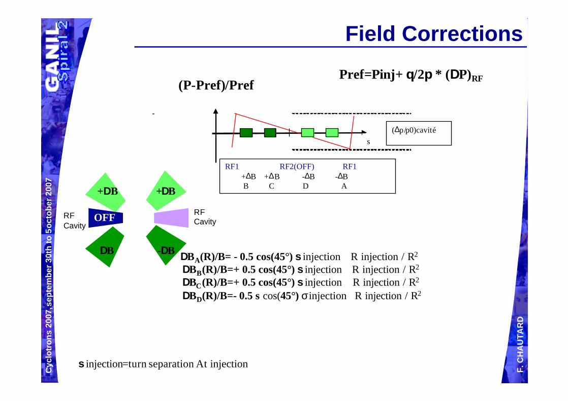
Field Corrections
∆BA(R)/B= - 0.5 cos(45°) σ injection R injection / R2
∆BB(R)/B=+ 0.5 cos(45°) σ injection R injection / R2
∆BC(R)/B=+ 0.5 cos(45°) σ injection R injection / R2
∆BD(R)/B=- 0.5 s cos(45°) σ injection R injection / R2
-
s
RF1 RF2(OFF) RF1+∆B +∆B -∆B -∆BB C D A
(∆p/p0)cavité
σ injection=turn separation At injection
(P-Pref)/PrefPref=Pinj+ θ/2π * (∆P)RF
∆B -∆B
+∆B +∆B
OFFRFCavity
RFCavity
Cyc
lotr
ons
2007
, sep
tem
ber3
0th
to 5
octo
ber2
007
F. C
HA
UTA
RD
Beam dynamics :
0
02 )(
1)
)(1
(''p
pps
xks
x−
=−+ρρ
0)()(
1)cos()(2)(
1))(
1('' 2 =∆
+≈−+B
sBzs
sss
xks
xρρρ
σρρ
ρσ
ρρ
ρρ
=∆
=∆
=
∆BB
pp
cavity1
Hill equation over 1 turn for the central trajectory
With 1 cavity => 1 defect per turn
With 1 cavity + field correction
=> |∆B (R)| /B= - 0.5 σ cos(s/R)/R
∆BA(R)/B= - 0.5 cos(45°) σ injection R injection / R2
∆BB(R)/B= + 0.5 cos(45°) σ injection R injection / R2
∆BC(R)/B= + 0.5 cos(45°) σ injection R injection / R2
∆BD(R)/B= - 0.5 s cos(45°) σ injection R injection / R2